JP2024180507A - Server and Programs - Google Patents
Server and ProgramsDownload PDFInfo
- Publication number
- JP2024180507A JP2024180507AJP2024177790AJP2024177790AJP2024180507AJP 2024180507 AJP2024180507 AJP 2024180507AJP 2024177790 AJP2024177790 AJP 2024177790AJP 2024177790 AJP2024177790 AJP 2024177790AJP 2024180507 AJP2024180507 AJP 2024180507A
- Authority
- JP
- Japan
- Prior art keywords
- packet
- kernel
- server
- thread
- delay control
- Prior art date
- Legal status (The legal status is an assumption and is not a legal conclusion. Google has not performed a legal analysis and makes no representation as to the accuracy of the status listed.)
- Pending
Links
Images


Classifications
- G—PHYSICS
- G06—COMPUTING OR CALCULATING; COUNTING
- G06F—ELECTRIC DIGITAL DATA PROCESSING
- G06F9/00—Arrangements for program control, e.g. control units
- G06F9/06—Arrangements for program control, e.g. control units using stored programs, i.e. using an internal store of processing equipment to receive or retain programs
- G06F9/46—Multiprogramming arrangements
- G06F9/54—Interprogram communication
- G06F9/545—Interprogram communication where tasks reside in different layers, e.g. user- and kernel-space
- G—PHYSICS
- G06—COMPUTING OR CALCULATING; COUNTING
- G06F—ELECTRIC DIGITAL DATA PROCESSING
- G06F9/00—Arrangements for program control, e.g. control units
- G06F9/06—Arrangements for program control, e.g. control units using stored programs, i.e. using an internal store of processing equipment to receive or retain programs
- G06F9/46—Multiprogramming arrangements
- G06F9/48—Program initiating; Program switching, e.g. by interrupt
- G06F9/4806—Task transfer initiation or dispatching
- G06F9/4812—Task transfer initiation or dispatching by interrupt, e.g. masked
- G—PHYSICS
- G06—COMPUTING OR CALCULATING; COUNTING
- G06F—ELECTRIC DIGITAL DATA PROCESSING
- G06F9/00—Arrangements for program control, e.g. control units
- G06F9/06—Arrangements for program control, e.g. control units using stored programs, i.e. using an internal store of processing equipment to receive or retain programs
- G06F9/44—Arrangements for executing specific programs
- G06F9/455—Emulation; Interpretation; Software simulation, e.g. virtualisation or emulation of application or operating system execution engines
- G06F9/45533—Hypervisors; Virtual machine monitors
- G06F9/45558—Hypervisor-specific management and integration aspects
- G—PHYSICS
- G06—COMPUTING OR CALCULATING; COUNTING
- G06F—ELECTRIC DIGITAL DATA PROCESSING
- G06F9/00—Arrangements for program control, e.g. control units
- G06F9/06—Arrangements for program control, e.g. control units using stored programs, i.e. using an internal store of processing equipment to receive or retain programs
- G06F9/46—Multiprogramming arrangements
- G06F9/48—Program initiating; Program switching, e.g. by interrupt
- G06F9/4806—Task transfer initiation or dispatching
- G06F9/4843—Task transfer initiation or dispatching by program, e.g. task dispatcher, supervisor, operating system
- G06F9/485—Task life-cycle, e.g. stopping, restarting, resuming execution
- H—ELECTRICITY
- H04—ELECTRIC COMMUNICATION TECHNIQUE
- H04L—TRANSMISSION OF DIGITAL INFORMATION, e.g. TELEGRAPHIC COMMUNICATION
- H04L47/00—Traffic control in data switching networks
- H04L47/50—Queue scheduling
- H04L47/56—Queue scheduling implementing delay-aware scheduling
- H04L47/568—Calendar queues or timing rings
- G—PHYSICS
- G06—COMPUTING OR CALCULATING; COUNTING
- G06F—ELECTRIC DIGITAL DATA PROCESSING
- G06F9/00—Arrangements for program control, e.g. control units
- G06F9/06—Arrangements for program control, e.g. control units using stored programs, i.e. using an internal store of processing equipment to receive or retain programs
- G06F9/44—Arrangements for executing specific programs
- G06F9/455—Emulation; Interpretation; Software simulation, e.g. virtualisation or emulation of application or operating system execution engines
- G06F9/45533—Hypervisors; Virtual machine monitors
- G06F9/45558—Hypervisor-specific management and integration aspects
- G06F2009/45595—Network integration; Enabling network access in virtual machine instances
Landscapes
- Engineering & Computer Science (AREA)
- Software Systems (AREA)
- Theoretical Computer Science (AREA)
- Physics & Mathematics (AREA)
- General Engineering & Computer Science (AREA)
- General Physics & Mathematics (AREA)
- Computer Networks & Wireless Communication (AREA)
- Signal Processing (AREA)
- Data Exchanges In Wide-Area Networks (AREA)
Abstract
Description
Translated fromJapanese本発明は、サーバ内遅延制御装置、サーバ内遅延制御方法およびプログラムに関する。The present invention relates to an intra-server delay control device, an intra-server delay control method, and a program.
NFV(Network Functions Virtualization:ネットワーク機能仮想化)による仮想化技術の進展などを背景に、サービス毎にシステムを構築して運用することが行われている。また、上記サービス毎にシステムを構築する形態から、サービス機能を再利用可能なモジュール単位に分割し、独立した仮想マシン(VM:Virtual Machineやコンテナなど)環境の上で動作させることで、部品のようにして必要に応じて利用し運用性を高めるといったSFC(Service Function Chaining)と呼ばれる形態が主流となりつつある。Against the backdrop of advances in virtualization technology such as NFV (Network Functions Virtualization), systems are being built and operated for each service. In addition, a form known as Service Function Chaining (SFC) is becoming mainstream, in which service functions are divided into reusable modules and run in independent virtual machine (VM: Virtual Machine, container, etc.) environments, allowing the functions to be used as components when needed and improving operability, as opposed to the form in which systems are built for each service.
仮想マシンを構成する技術としてLinux(登録商標)とKVM(kernel-based virtual machine)で構成されたハイパーバイザー環境が知られている。この環境では、KVMモジュールが組み込まれたHost OS(物理サーバ上にインストールされたOSをHost OSと呼ぶ)がハイパーバイザーとしてカーネル空間と呼ばれるユーザ空間とは異なるメモリ領域で動作する。この環境においてユーザ空間にて仮想マシンが動作し、その仮想マシン内にGuest OS(仮想マシン上にインストールされたOSをGuest OSと呼ぶ)が動作する。A known technology for configuring virtual machines is a hypervisor environment consisting of Linux (registered trademark) and KVM (kernel-based virtual machine). In this environment, a Host OS (an OS installed on a physical server is called a Host OS) with a built-in KVM module operates as a hypervisor in a memory area called kernel space, which is different from the user space. In this environment, a virtual machine operates in the user space, and a Guest OS (an OS installed on a virtual machine is called a Guest OS) operates within that virtual machine.
Guest OSが動作する仮想マシンは、Host OSが動作する物理サーバとは異なり、(イーサーネットカードデバイスなどに代表される)ネットワークデバイスを含むすべてのHW(hardware)が、HWからGuest OSへの割込処理やGuest OSからハードウェアへの書き込みに必要なレジスタ制御となる。このようなレジスタ制御では、本来物理ハードウェアが実行すべき通知や処理がソフトウェアで擬似的に模倣されるため、性能がHost OS環境に比べ、低いことが一般的である。In a virtual machine running a Guest OS, unlike a physical server running a Host OS, all HW (hardware), including network devices (such as Ethernet card devices), are subject to the register control required for interrupt processing from the HW to the Guest OS and writing from the Guest OS to the hardware. With this type of register control, notifications and processing that should be performed by physical hardware are simulated by software, so performance is generally lower than in a Host OS environment.
この性能劣化において、特にGuest OSから自仮想マシン外に存在するHost OSや外部プロセスに対して、HWの模倣を削減し、高速かつ統一的なインターフェイスにより通信の性能と汎用性を向上させる技術がある。この技術として、virtioというデバイスの抽象化技術、つまり準仮想化技術が開発されており、すでにLinux(登録商標)を始め、FreeBSD(登録商標)など多くの汎用OSに組み込まれ、現在利用されている。To address this performance degradation, there is a technology that reduces the emulation of HW, particularly from the guest OS to the host OS and external processes that exist outside the virtual machine, and improves communication performance and versatility through a high-speed, unified interface. One such technology is a device abstraction technology called virtio, or paravirtualization technology, which has already been incorporated into many general-purpose operating systems, including Linux (registered trademark) and FreeBSD (registered trademark), and is currently in use.
virtioでは、コンソール、ファイル入出力、ネットワーク通信といったデータ入出力に関して、転送データの単一方向の転送用トランスポートとして、リングバッファで設計されたキューによるデータ交換をキューのオペレーションにより定義している。そして、virtioのキューの仕様を利用して、それぞれのデバイスに適したキューの個数と大きさをGuest OS起動時に用意することにより、Guest OSと自仮想マシン外部との通信を、ハードウェアエミュレーションを実行せずにキューによるオペレーションだけで実現することができる。In virtio, for data input/output such as console, file input/output, and network communication, data exchange using queues designed with ring buffers is defined by queue operations as a one-way transport for data transfer. By using the virtio queue specifications to prepare the number and size of queues appropriate for each device when the Guest OS starts, communication between the Guest OS and outside the virtual machine can be achieved using only queue operations without performing hardware emulation.
[割込モデルによるパケット転送(汎用VM構成の例)]
図9は、汎用Linux kernel(登録商標)およびVM構成のサーバ仮想化環境における、割込モデルによるパケット転送を説明する図である。
HW10は、NIC(Network Interface Card)11(物理NIC)(インターフェイス部)を有し、Host OS20、仮想マシンを構築するハイパーバイザーであるKVM30、仮想マシン(VM1,VM2)40、およびGuest OS50により構築された仮想通信路を経由してuser space(ユーザスペース)60上のパケット処理APL(Application)1との間でデータ送受信の通信を行う。以下の説明において、図9の太矢印に示すように、パケット処理APL1が、HW10からのパケットを受け取るデータの流れをRx側受信と称し、パケット処理APL1が、HW10にパケットを送信するデータの流れをTx側送信と称する。[Packet forwarding using interrupt model (general purpose VM configuration)]
FIG. 9 is a diagram for explaining packet transfer according to an interrupt model in a server virtualization environment having a generic Linux kernel (registered trademark) and a VM configuration.
The HW 10 has a NIC (Network Interface Card) 11 (physical NIC) (interface unit), and transmits and receives data to and from a packet processing APL (Application) 1 on a
Host OS20は、kernel21、Ring Buffer22、およびDriver23を有し、kernel21は、kernel threadであるvhost-netモジュール221と、tapデバイス222と、仮想スイッチ(br)223と、を有する。The host OS 20 has a
tapデバイス222は、仮想ネットワークのカーネルデバイスであり、ソフトウェアでサポートされている。仮想マシン(VM1)40は、仮想ブリッジ(bridge)に作成される仮想スイッチ(br)223を介してGuest OS50とHost OS20が通信できる。tapデバイス222は、この仮想ブリッジに作成されるGuest OS50の仮想NIC(vNIC)と繋がるデバイスである。The
Host OS20は、Guest OS50の仮想マシン内で構築された構成情報(共有バッファキューの大きさ、キューの数、識別子、リングバッファへアクセスするための先頭アドレス情報など)をvhost-netモジュール221にコピーし、仮想マシン側の端点の情報をHost OS20内部に構築する。このvhost-netモジュール221は、virtioネットワーキング用のカーネルレベルのバックエンドであり、virtioパケット処理タスクをユーザ領域(ユーザ空間)からkernel21のvhost-netモジュール221に移すことで仮想化のオーバーヘッドを低減できる。The
Guest OS50は、仮想マシン(VM1)上にインストールされたGuest OS(Guest1)と、仮想マシン(VM2)上にインストールされたGuest OS(Guest2)と、を有し、仮想マシン(VM1,VM2)40内でGuest OS50(Guest1,Guest2)が動作する。Guest OS50として、Guest1を例に採ると、Guest OS50(Guest1)は、kernel51、Ring Buffer52、およびDriver53を有し、Driver53は、virtio-driver531を備える。The Guest OS 50 has a Guest OS (Guest 1) installed on a virtual machine (VM1) and a Guest OS (Guest 2) installed on a virtual machine (VM2), and the Guest OS 50 (
具体的には、PCI(Peripheral Component Interconnect)デバイスとして仮想マシン内にコンソール、ファイル入出力、ネットワーク通信それぞれに対しvirtioデバイスが存在し(コンソールはvirtio-console、ファイル入出力はvirtio-blk、ネットワークはvirtio-netと呼ばれるデバイスとそれに対応するOSが持つドライバがvirtioキューで定義されている)、Guest OS起動時に、Guest OSと相手側とのデータの受け渡し端点(送受信端点)を2つ作り、データ送受信の親子関係を構築する。多くの場合、親子関係は仮想マシン側(子側)とGuest OS(親側)で構成する。Specifically, within the virtual machine, there are virtio devices for the console, file I/O, and network communication as PCI (Peripheral Component Interconnect) devices (the console is virtio-console, file I/O is virtio-blk, and the network is virtio-net, and the corresponding drivers that the OS has are defined in the virtio queue), and when the Guest OS starts up, two data transfer endpoints (transmission and reception endpoints) are created between the Guest OS and the other side, and a parent-child relationship for data transmission and reception is established. In many cases, the parent-child relationship is configured between the virtual machine (child side) and the Guest OS (parent side).
子側は仮想マシン内のデバイスの構成情報として存在し、それぞれのデータ領域のサイズと必要とする端点の組み合わせの個数、デバイスの種別を親側に要求する。親側は子側の要求に従い、必要な分のデータを貯蓄し受け渡すための共有バッファキューのためのメモリを割り当て確保し、子側がアクセスできるようにそのアドレス番地を子側に返す。データの受け渡しに必要とされる共有バッファキューのオペレーションについては、virtioではすべて共通であり、親側、子側両方合意済みとして実行される。さらに共有バッファキューの大きさも両方合意済みとする(つまりデバイスごとに決まっている)。これにより、子側にアドレスを伝えるだけで、親側、子側の双方が共有するキューを操作することが可能となる。The child side exists as device configuration information within the virtual machine, and requests the parent side for the size of each data area, the number of endpoint combinations required, and the device type. In accordance with the child side's request, the parent side allocates and secures memory for a shared buffer queue to store and transfer the required amount of data, and returns the address to the child side so that the child can access it. In Virtio, all shared buffer queue operations required for data transfer are common, and are executed with both the parent and child sides having agreed upon them. Furthermore, the size of the shared buffer queue is also agreed upon by both sides (i.e. it is determined for each device). This makes it possible for both the parent and child sides to operate the shared queue simply by communicating the address to the child side.
virtioにおいて用意する共有バッファキューは単一方向用として用意されるため、例えば、virtio-netデバイスと呼ばれる仮想ネットワークデバイスでは送信用、受信用、コントロール用の3つのRing Buffer52で構成される。親と子の通信は、共有バッファキューへの書き込みとバッファ更新通知により実現し、Ring Buffer52に書き込んだ後、相手側に通知する。相手側は通知を受けると、どの共有バッファキューにどの程度新規のデータが入っているのかをvirtioの共通オペレーションを利用して確認し、新規のバッファ領域を取り出す。これにより、親から子または子から親へのデータの受け渡しが成立する。The shared buffer queues prepared in virtio are prepared for single direction use, so for example, a virtual network device called a virtio-net device is composed of three
以上のように、親子でお互いデータ交換用のRing Buffer52とそれぞれのリングバッファ用のオペレーション方法(virtioで共通)を共有することにより、ハードウェアエミュレーションを必要としない、Guest OS50と外部との通信を実現する。これにより、従来のハードウェアエミュレーションに比べ、Guest OS50と外部とのデータの送受信を高速に実現することが可能である。As described above, by sharing the
仮想マシン内のGuest OS50が外部と通信する場合は、子側が外部と接続し、子側が外部と親側の中継役としてデータを送受信する必要がある。例えば、Guest OS50とHost OS20間の通信がその例の1つである。ここで、外部をHost OS20とした場合、既存の通信方法として2パターン存在する。When Guest OS 50 in a virtual machine communicates with the outside, the child side must connect to the outside and act as a relay between the outside and the parent side to send and receive data. One example is communication between Guest OS 50 and Host OS 20. Here, if the outside is Host
第1の方法(以下、外部通信方式1と呼ぶ)は、仮想マシン内に子側の端点を構築し、Guest OS50と仮想マシン間の通信と、Host OS20が提供する通信端点(通常、tap/tunデバイスと呼ばれる)を、仮想マシン内で接続する。この接続により以下のとおりの接続を構築し、Guest OS50からHost OS20への通信を実現する。The first method (hereafter referred to as external communication method 1) establishes a child endpoint within the virtual machine, and connects the communication between Guest OS 50 and the virtual machine to a communication endpoint provided by Host OS 20 (usually called a tap/tun device) within the virtual machine. This connection establishes the following connection, realizing communication from Guest OS 50 to Host
このとき、Guest OS50はtapドライバやHost OS20が動作するカーネル空間というメモリ領域とは異なる権限を持つユーザ空間であるメモリ領域で動作している。このため、Guest OS50からHost OS20への通信には最低1回メモリコピーが発生してしまう。At this time, Guest OS 50 runs in a memory area called user space, which has different permissions from the memory area called kernel space in which the tap driver and
第2の方法(以下、外部通信方式2と呼ぶ)は、これを解決する手段として、vhost-netという技術が存在する。vhost-netでは一度仮想マシン内で構築された親側の構成情報(共有バッファキューの大きさ、キューの数、識別子、リングバッファへアクセスするための先頭アドレス情報など)をHost OS20内部のvhost-netモジュール221にコピーし、子側の端点の情報をホスト内部に構築する。この構築により、共有バッファキューの操作をGuest OS50とHost OS20間で直接実施することを可能とする技術である。これにより、コピーは実質0回で済むようになり、virtio-netに比べ、コピー回数が1回少ない分、外部通信方式1と比較し、より高速にデータ転送が実現できる。The second method (hereafter referred to as external communication method 2) is a technology called vhost-net that solves this problem. With vhost-net, the parent configuration information (size of the shared buffer queue, number of queues, identifier, top address information for accessing the ring buffer, etc.) that was once constructed within the virtual machine is copied to the vhost-
このように、virtioで接続されたHost OS20とGuest OS50において、virtio-net関連のメモリコピー回数を減らすことにより、パケット転送処理を高速化することができる。In this way, by reducing the number of virtio-net-related memory copies in the Host OS 20 and Guest OS 50 connected by virtio, packet forwarding processing can be accelerated.
なお、kernel v4.10(2017.2~)以降、tapインターフェイスの仕様変更があり、tapデバイスから挿入されたパケットは、tapデバイスへパケットコピーを行った処理と同一コンテキスト内で完結されるようになった。これにより、ソフトウェア割込(softIRQ)の発生がなくなった。In addition, since kernel v4.10 (2017.2~), the specifications of the tap interface have been changed, and packets inserted from the tap device are now completed within the same context as the process that copied the packet to the tap device. This means that software interrupts (softIRQs) no longer occur.
[ポーリングモデルによるパケット転送(DPDKの例)]
複数の仮想マシンを接続、連携させる手法はInter-VM Communicationと呼ばれ、データセンタなどの大規模な環境では、VM間の接続に、仮想スイッチが標準的に利用されてきた。しかし、通信の遅延が大きい手法であることから、より高速な手法が新たに提案されている。例えば、SR-IOV(Single Root I/O Virtualization)と呼ばれる特別なハードウェアを用いる手法や、高速パケット処理ライブラリであるIntel DPDK(Intel Data Plane Development Kit)(以下、DPDKという)を用いたソフトウェアによる手法などが提案されている(非特許文献1参照)。[Packet forwarding using polling model (DPDK example)]
The method of connecting and coordinating multiple virtual machines is called Inter-VM Communication, and in large-scale environments such as data centers, virtual switches have been used as a standard method for connecting VMs. However, since this method has a large communication delay, new faster methods have been proposed. For example, a method using special hardware called SR-IOV (Single Root I/O Virtualization) and a software method using Intel DPDK (Intel Data Plane Development Kit) (hereinafter referred to as DPDK), a high-speed packet processing library, have been proposed (see Non-Patent Document 1).
DPDKは、従来Linux kernel(登録商標)が行っていたNIC(Network Interface Card)の制御をユーザ空間で行うためのフレームワークである。Linux kernelにおける処理との最大の違いは、PMD(Pull Mode Driver)と呼ばれるポーリングベースの受信機構を持つことである。通常、Linux kernelでは、NICへのデータの到達を受けて、割込が発生し、それを契機に受信処理が実行される。一方、PMDは、データ到達の確認や受信処理を専用のスレッドが継続的に行う。コンテキストスイッチや割込などのオーバーヘッドを排除することで高速なパケット処理を行うことができる。DPDKは、パケット処理のパフォーマンスとスループットを大幅に高めて、データプレーン・アプリケーション処理に多くの時間を確保することを可能にする。DPDK is a framework for controlling NICs (Network Interface Cards), which was previously handled by the Linux kernel (registered trademark), in user space. The biggest difference with the processing in the Linux kernel is that it has a polling-based reception mechanism called PMD (Pull Mode Driver). Normally, in the Linux kernel, an interrupt occurs when data arrives at the NIC, which triggers the execution of reception processing. On the other hand, in the PMD, a dedicated thread continuously checks whether data has arrived and performs reception processing. By eliminating overhead such as context switches and interrupts, high-speed packet processing can be achieved. DPDK significantly improves the performance and throughput of packet processing, making it possible to secure more time for data plane application processing.
DPDKは、CPU(Central Processing Unit)やNICなどのコンピュータ資源を占有的に使用する。このため、SFCのようにモジュール単位で柔軟につなぎ替える用途には適用しづらい。これを緩和するためのアプリケーションであるSPP(Soft Patch Panel)がある。SPPは、VM間に共有メモリを用意し、各VMが同じメモリ空間を直接参照できる構成にすることで、仮想化層でのパケットコピーを省略する。また、物理NICと共有メモリ間のパケットのやり取りには、DPDKを用いて高速化を実現する。SPPは、各VMのメモリ交換の参照先を制御することで、パケットの入力先、出力先をソフトウェア的に変更することができる。この処理によって、SPPは、VM間やVMと物理NIC間の動的な接続切替を実現する。DPDK exclusively uses computer resources such as the CPU (Central Processing Unit) and NIC. For this reason, it is difficult to apply to applications that require flexible reconnection on a module basis, like SFC. There is an application called SPP (Soft Patch Panel) that alleviates this problem. SPP prepares shared memory between VMs and configures each VM to directly reference the same memory space, thereby eliminating packet copying in the virtualization layer. In addition, DPDK is used to speed up packet exchange between physical NICs and shared memory. SPP can change the input and output destinations of packets using software by controlling the reference destination of memory exchange for each VM. Through this process, SPP realizes dynamic connection switching between VMs and between VMs and physical NICs.
図10は、OvS-DPDK(Open vSwitch with DPDK)の構成における、ポーリングモデルによるパケット転送を説明する図である。図9と同一構成部分には、同一符号を付して重複箇所の説明を省略する。
図10に示すように、Host OS20は、パケット処理のためのソフトウェアであるOvS-DPDK70を備え、OvS-DPDK70は、仮想マシン(ここではVM1)に接続するための機能部であるvhost-user71と、NIC(DPDK)11(物理NIC)に接続するための機能部であるdpdk(PMD)72と、を有する。
また、パケット処理APL1Aは、Guest OS50区間においてポーリングを行う機能部であるdpdk(PMD)2を具備する。すなわち、パケット処理APL1Aは、図9のパケット処理APL1にdpdk(PMD)2を具備させて、パケット処理APL1を改変したAPLである。 10 is a diagram for explaining packet forwarding by a polling model in the configuration of OvS-DPDK (Open vSwitch with DPDK). The same components as those in FIG. 9 are given the same reference numerals and the description of the overlapping parts is omitted.
As shown in FIG. 10, the
The packet processing APL1A also includes a dpdk(PMD)2 which is a functional unit that performs polling in the
ポーリングモデルによるパケット転送は、DPDKの拡張として、共有メモリを介してゼロコピーでHost OS20とGuest OS50間、および、Guest OS50間のパケットコピーを高速に行うSPPにおいて、GUIにより経路操作を可能とする。As an extension of DPDK, packet forwarding using the polling model enables route manipulation using a GUI in an SPP that performs high-speed zero-copy packet copying between
[New API(NAPI)によるRx側パケット処理]
図11は、Linux kernel 2.5/2.6より実装されているNew API(NAPI)によるRx側パケット処理の概略図である(非特許文献2参照)。図9と同一構成部分には、同一符号を付している。
図11に示すように、New API(NAPI)は、OS70(例えば、Host OS)を備えるサーバ上で、ユーザが使用可能なuser space60に配置されたパケット処理APL1を実行し、OS70に接続されたHW10のNIC11とパケット処理APL1との間でパケット転送を行う。[Rx side packet processing using New API (NAPI)]
Fig. 11 is a schematic diagram of Rx-side packet processing by New API (NAPI) implemented in Linux kernel 2.5/2.6 (see Non-Patent Document 2). The same components as those in Fig. 9 are given the same reference numerals.
As shown in FIG. 11, the New API (NAPI) executes a packet processing APL1 placed in a
OS70は、kernel71、Ring Buffer72、およびDriver73を有し、kernel71は、プロトコル処理部74を有する。
Kernel71は、OS70(例えば、Host OS)の基幹部分の機能であり、ハードウェアの監視やプログラムの実行状態をプロセス単位で管理する。ここでは、kernel71は、パケット処理APL1からの要求に応えるとともに、HW10からの要求をパケット処理APL1に伝える。Kernel71は、パケット処理APL1からの要求に対して、システムコール(「非特権モードで動作しているユーザプログラム」が「特権モードで動作しているカーネル」に処理を依頼)を介することで処理する。
Kernel71は、Socket75を介して、パケット処理APL1へパケットを伝達する。Kernel71は、Socket75を介してパケット処理APL1からパケットを受信する。 The
The
The
Ring Buffer72は、Kernel71が管理し、サーバ中のメモリ空間にある。Ring Buffer72は、Kernel71が出力するメッセージをログとして格納する一定サイズのバッファであり、上限サイズを超過すると先頭から上書きされる。
Driver73は、kernel71でハードウェアの監視を行うためデバイスドライバである。なお、Driver73は、kernel71に依存し、作成された(ビルドされた)カーネルソースが変われば、別物になる。この場合、該当ドライバ・ソースを入手し、ドライバを使用するOS上で再ビルドし、ドライバを作成することになる。Driver73 is a device driver that monitors the hardware in kernel71. Driver73 depends on kernel71, and becomes a different driver if the created (built) kernel source changes. In this case, you will need to obtain the driver source, rebuild it on the OS that uses the driver, and create the driver.
プロトコル処理部74は、OSI(Open Systems Interconnection)参照モデルが定義するL2(データリンク層)/L3(ネットワーク層)/L4(トランスポート層)のプロトコル処理を行う。The protocol processing unit 74 performs protocol processing for L2 (data link layer), L3 (network layer), and L4 (transport layer) defined by the OSI (Open Systems Interconnection) reference model.
Socket75は、kernel71がプロセス間通信を行うためのインターフェイスである。Socket75は、ソケットバッファを有し、データのコピー処理を頻繁に発生させない。Socket75を介しての通信確立までの流れは、下記の通りである。1.サーバ側がクライアントを受け付けるソケットファイルを作成する。2.受付用ソケットファイルに名前をつける。3.ソケット・キューを作成する。4.ソケット・キューに入っているクライアントからの接続の最初の1つを受け付ける。5.クライアント側ではソケットファイルを作成する。6.クライアント側からサーバへ接続要求を出す。7.サーバ側で、受付用ソケットファイルとは別に、接続用ソケットファイルを作成する。通信確立の結果、パケット処理APL1は、kernel71に対してread()やwrite()などのシステムコールを呼び出せるようになる。Socket 75 is an interface that
以上の構成において、Kernel71は、NIC11からのパケット到着の知らせを、ハードウェア割込(hardIRQ)により受け取り、パケット処理のためのソフトウェア割込(softIRQ)をスケジューリングする。
上記、Linux kernel 2.5/2.6より実装されているNew API(NAPI)は、パケットが到着するとハードウェア割込(hardIRQ)の後、ソフトウェア割込(softIRQ)により、パケット処理を行う。図11に示すように、割込モデルによるパケット転送は、割込処理(図11の符号c参照)によりパケットの転送を行うため、割込処理の待ち合わせが発生し、パケット転送の遅延が大きくなる。 In the above configuration, the
The New API (NAPI) implemented in the Linux kernel 2.5/2.6 performs packet processing by a software interrupt (softIRQ) after a hardware interrupt (hardIRQ) when a packet arrives. As shown in Fig. 11, packet transfer based on the interrupt model transfers packets by interrupt processing (see symbol c in Fig. 11), which creates a wait for the interrupt processing and increases the delay in packet transfer.
以下、NAPI Rx側パケット処理概要について説明する。
[New API(NAPI)によるRx側パケット処理構成]
図12は、図11の破線で囲んだ箇所におけるNew API(NAPI)によるRx側パケット処理の概要を説明する図である。
<Device driver>
図12に示すように、Device driverには、ネットワークインターフェースカードであるNIC11(物理NIC)、NIC11の処理要求の発生によって呼び出され要求された処理(ハードウェア割込)を実行するハンドラであるhardIRQ81、およびソフトウェア割込の処理機能部であるnetif_rx82が配置される。 The following provides an overview of packet processing on the NAPI Rx side.
[Rx side packet processing configuration using New API (NAPI)]
FIG. 12 is a diagram for explaining an outline of Rx-side packet processing by New API (NAPI) in the area surrounded by the dashed line in FIG.
<Device driver>
As shown in FIG. 12, the device driver includes a NIC 11 (physical NIC), which is a network interface card, hardIRQ 81, which is a handler that is called when a processing request is made to the
<Networking layer>
Networking layerには、netif_rx82の処理要求の発生によって呼び出され要求された処理(ソフトウェア割込)を実行するハンドラであるsoftIRQ83、ソフトウェア割込(softIRQ)の実体を行う制御機能部であるdo_softirq84が配置される。また、ソフトウェア割込(softIRQ)を受けて実行するパケット処理機能部であるnet_rx_action85、NIC11からのハードウェア割込がどのデバイスのものであるかを示すネットデバイス(net_device)の情報を登録するpoll_list86、sk_buff構造体(Kernel71が、パケットがどうなっているかを知覚できるようにするための構造体)を作成するnetif_receive_skb87、Ring Buffer72が配置される。 <Networking layer>
In the networking layer, there are disposed softIRQ 83, which is a handler that is called by the occurrence of a processing request of netif_rx 82 and executes the requested processing (software interrupt), and do_softirq 84, which is a control function unit that executes the substance of the software interrupt (softIRQ).In addition, there are disposed net_rx_action 85, which is a packet processing function unit that receives and executes the software interrupt (softIRQ), poll_list 86, which registers information on the net device (net_device) that indicates which device the hardware interrupt from the
<Protocol layer>
Protocol layerには、パケット処理機能部であるip_rcv88、arp_rcv89等が配置される。 <Protocol layer>
In the protocol layer, packet processing function units such as ip_rcv 88 and arp_rcv 89 are arranged.
上記netif_rx82、do_softirq84、net_rx_action85、netif_receive_skb87、ip_rcv88、およびarp_rcv89は、Kernel71の中でパケット処理のために用いられるプログラムの部品(関数の名称)である。The above netif_rx 82, do_softirq 84, net_rx_action 85, netif_receive_skb 87, ip_rcv 88, and arp_rcv 89 are program components (function names) used for packet processing within
[New API(NAPI)によるRx側パケット処理動作]
図12の矢印(符号)d~oは、Rx側パケット処理の流れを示している。
NIC11のhardware機能部11a(以下、NIC11という)が、対向装置からフレーム内にパケット(またはフレーム)を受信すると、DMA(Direct Memory Access)転送によりCPUを使用せずに、Ring Buffer72へ到着したパケットをコピーする(図12の符号d参照)。このRing Buffer72は、サーバの中にあるメモリ空間で、Kernel71(図11参照)が管理している。[Rx side packet processing operation using New API (NAPI)]
The arrows (symbols) d to o in FIG. 12 indicate the flow of packet processing on the Rx side.
When the hardware function unit 11a of the NIC 11 (hereinafter referred to as the NIC 11) receives a packet (or a frame) in a frame from the other device, it copies the arriving packet to the
しかし、NIC11が、Ring Buffer72へ到着したパケットをコピーしただけでは、Kernel71は、そのパケットを認知できない。そこで、NIC11は、パケットが到着すると、ハードウェア割込(hardIRQ)をhardIRQ81に上げ(図12の符号e参照)、netif_rx82が下記の処理を実行することで、Kernel71は、当該パケットを認知する。なお、図12の楕円で囲んで示すhardIRQ81は、機能部ではなくハンドラを表記する。However, if the
netif_rx82は、実際に処理をする機能であり、hardIRQ81(ハンドラ)が立ち上がると(図12の符号f参照)、poll_list86に、ハードウェア割込(hardIRQ)の中身の情報の1つである、NIC11からのハードウェア割込がどのデバイスのものであるかを示すネットデバイス(net_device)の情報を保存して、キューの刈取り(バッファに溜まっているパケットの中身を参照して、そのパケットの処理を、次に行う処理を考慮してバッファから該当するキューのエントリを削除する)を登録する(図12の符号g参照)。具体的には、netif_rx82は、Ring Buffer72にパケットが詰め込まれたことを受けて、NIC11のドライバを使って、以後のキューの刈取りをpoll_list86に登録する(図12の符号g参照)。これにより、poll_list86には、Ring Buffer72にパケットが詰め込まれたことによる、キューの刈取り情報が登録される。When hardIRQ 81 (handler) is started (see symbol f in FIG. 12), netif_rx 82 saves the net device (net_device) information, which is one of the pieces of information in the hardware interrupt (hardIRQ), in poll_list 86, indicating which device the hardware interrupt from
このように、図12の<Device driver>において、NIC11は、パケットを受信すると、DMA転送によりRing Buffer72へ到着したパケットをコピーする。また、NIC11は、hardIRQ81(ハンドラ)を上げ、netif_rx82は、poll_list86にnet_deviceを登録し、ソフトウェア割込(softIRQ)をスケジューリングする。
ここまでで、図12の<Device driver>におけるハードウェア割込の処理は停止する。 12, when the
At this point, the hardware interrupt processing in the <Device driver> in FIG. 12 stops.
その後、netif_rx82は、poll_list86に積まれているキューに入っている情報(具体的にはポインタ)を用いて、Ring Buffer72に格納されているデータを刈取ることを、ソフトウェア割込(softIRQ)でsoftIRQ83(ハンドラ)に上げ(図12の符号h参照)、ソフトウェア割込の制御機能部であるdo_softirq84に通知する(図12の符号i参照)。Then, netif_rx 82 uses the information (specifically, the pointer) in the queue stored in poll_list 86 to raise a software interrupt (softIRQ) to softIRQ 83 (handler) to harvest the data stored in Ring Buffer 72 (see symbol h in Figure 12), and notifies do_softirq 84, which is the software interrupt control function unit (see symbol i in Figure 12).
do_softirq84は、ソフトウェア割込制御機能部であり、ソフトウェア割込の各機能を定義(パケット処理は各種あり、割込処理はそのうちの一つ。割込処理を定義する)している。do_softirq84fは、この定義をもとに、実際にソフトウェア割込処理を行うnet_rx_action85に、今回の(該当の)ソフトウェア割込の依頼を通知する(図12の符号j参照)。do_softirq 84 is a software interrupt control function unit that defines each function of the software interrupt (there are various types of packet processing, and interrupt processing is one of them. This defines the interrupt processing). Based on this definition, do_softirq 84f notifies net_rx_action 85, which actually processes the software interrupt, of the current (relevant) software interrupt request (see symbol j in Figure 12).
net_rx_action85は、softIRQの順番がまわってくると、poll_list86に登録されたnet_deviceをもとに(図12の符号k参照)、Ring Buffer72からパケットを刈取るためのポーリングルーチンを呼び出し、パケットを刈取る(図12の符号l参照)。このとき、net_rx_action85は、poll_list86が空になるまで刈取りを続ける。
その後、net_rx_action85は、netif_receive_skb87に通達をする(図12の符号m参照)。 When the turn of the softIRQ comes, the net_rx_action 85 calls a polling routine for reaping packets from the
Thereafter, net_rx_action 85 notifies netif_receive_skb 87 (see symbol m in FIG. 12).
netif_receive_skb87は、sk_buff構造体を作り、パケットの内容を解析し、タイプ毎に後段のプロトコル処理部74(図11参照)へ処理をまわす。すなわち、netif_receive_skb87は、パケットの中身を解析し、パケットの中身に応じて処理をする場合には、<Protocol layer>のip_rcv88に処理を回し(図12の符号n)、また、例えばL2であればarp_rcv89に処理をまわす(図12の符号o)。The netif_receive_skb 87 creates an sk_buff structure, analyzes the contents of the packet, and passes the processing to the downstream protocol processing unit 74 (see FIG. 11) for each type. That is, the netif_receive_skb 87 analyzes the contents of the packet, and if processing is to be performed according to the contents of the packet, passes the processing to the ip_rcv 88 of the <Protocol layer> (n in FIG. 12), or, for example, to the arp_rcv 89 if it is L2 (o in FIG. 12).
非特許文献3には、サーバ内ネットワーク遅延制御装置(KBP:Kernel Busy Poll)が記載されている。KBPは、kernel内でpollingモデルによりパケット到着を常時監視する。これにより、softIRQを抑止し、低遅延なパケット処理を実現する。Non-Patent Document 3 describes a server network delay control device (KBP: Kernel Busy Poll). KBP constantly monitors packet arrivals within the kernel using a polling model. This suppresses softIRQ and achieves low-latency packet processing.
しかしながら、割込モデルとポーリングモデルによるパケット転送のいずれについても下記課題がある。
割込モデルは、HWからイベント(ハードウェア割込)を受けたkernelがパケット加工を行うためのソフトウェア割込処理によってパケット転送を行う。このため、割込モデルは、割込(ソフトウェア割込)処理によりパケット転送を行うので、他の割込との競合や、割込先CPUがより優先度の高いプロセスに使用されていると待ち合わせが発生し、パケット転送の遅延が大きくなるといった課題がある。この場合、割込処理が混雑すると、更に待ち合わせ遅延は大きくなる。
例えば、図9に示すように、割込モデルによるパケット転送は、割込処理(図9の符号a,b参照)によりパケットの転送を行うため、割込処理の待ち合わせが発生し、パケット転送の遅延が大きくなる。 However, both packet transfer using the interrupt model and the polling model have the following problems.
In the interrupt model, the kernel receives an event (hardware interrupt) from the HW and uses software interrupt processing to process the packets. Therefore, since the interrupt model transfers packets using interrupt (software interrupt) processing, there are issues such as conflicts with other interrupts and waiting when the interrupt destination CPU is used by a process with a higher priority, resulting in large delays in packet transfer. In this case, if the interrupt processing becomes congested, the waiting delays will become even larger.
For example, as shown in FIG. 9, packet transfer according to the interrupt model transfers packets by interrupt processing (see symbols a and b in FIG. 9), so that waiting for the interrupt processing occurs, resulting in a large delay in packet transfer.
割込モデルにおいて、遅延が発生するメカニズムについて補足する。
一般的なkernelは、パケット転送処理はハードウェア割込処理の後、ソフトウェア割込処理にて伝達される。
パケット転送処理のソフトウェア割込が発生した際に、下記条件(1)~(3)においては、前記ソフトウェア割込処理を即時に実行することができない。このため、ksoftirqd(CPU毎のカーネルスレッドであり、ソフトウェア割込の負荷が高くなったときに実行される)等のスケジューラにより調停され、割込処理がスケジューリングされることにより、msオーダの待ち合わせが発生する。
(1)他のハードウェア割込処理と競合した場合
(2)他のソフトウェア割込処理と競合した場合
(3)優先度の高い他プロセスやkernel thread(migration thread等)、割込先CPUが使用されている場合
上記条件では、前記ソフトウェア割込処理を即時に実行することができない。 The mechanism by which delay occurs in the interrupt model will be explained below.
In a typical kernel, packet transfer processing is performed by hardware interrupt processing and then software interrupt processing.
When a software interrupt occurs in packet forwarding processing, the software interrupt processing cannot be executed immediately under the following conditions (1) to (3). Therefore, the software interrupt processing is scheduled by arbitration using a scheduler such as ksoftirqd (a kernel thread for each CPU that is executed when the load of the software interrupt becomes high), resulting in a wait on the order of ms.
(1) When there is conflict with other hardware interrupt processing; (2) When there is conflict with other software interrupt processing; (3) When other processes with higher priority, kernel threads (migration threads, etc.), or the interrupt destination CPU are in use. Under the above conditions, the software interrupt processing cannot be executed immediately.
また、New API(NAPI)によるパケット処理についても同様に、図12の破線囲みpに示すように、割込処理(softIRQ)の競合に起因し、msオーダのNW遅延が発生する。Similarly, in packet processing using New API (NAPI), as shown in the dotted line box p in Figure 12, network delays on the order of ms occur due to conflicts in interrupt processing (softIRQ).
一方、ポーリングモデルは、CPUを占有して通信キューをポーリングし、パケット到着時に即時刈取る。ポーリングモデルは、転送遅延を小さくすることが可能であるものの、APLにポーリング機能を具備させる必要が生じるので、APLに改変が必要である。
例えば、図10に示すように、ポーリングモデルによるパケット転送は、パケット処理APL1にGuest OS50区間においてポーリングを行う機能部であるdpdk(PMD)72を具備させる必要があり、パケット処理APL1の改変が必要となる。 On the other hand, the polling model occupies the CPU to poll the communication queue and immediately harvests packets when they arrive. Although the polling model can reduce transfer delays, it requires the APL to be equipped with a polling function, which requires modification of the APL.
For example, as shown in FIG. 10, packet transfer according to the polling model requires the packet processing APL1 to be provided with a dpdk(PMD) 72, which is a functional unit that performs polling in the
また、非特許文献3に記載のKBPは、kernel内でpollingモデルによりパケット到着を常時監視することで、softIRQを抑止し、低遅延なパケット処理を実現することができる。
しかし、パケット到着を常時監視するkernel threadがCPUコアを専有し、常にCPUタイムを使用するため、消費電力が高くなる課題がある。図13および図14を参照して、ワークロードとCPU使用率の関係について説明する。 Moreover, the KBP described in Non-Patent Document 3 can suppress softIRQ and realize low-latency packet processing by constantly monitoring packet arrivals using a polling model within the kernel.
However, since the kernel thread that constantly monitors the arrival of packets occupies a CPU core and constantly uses CPU time, there is a problem that power consumption is high. The relationship between the workload and the CPU utilization rate will be described with reference to Figs. 13 and 14.
図13は、映像(30FPS)のデータ転送例である。図13に示すワークロードは、転送レート350Mbpsで、30msごとに間欠的にデータ転送を行っている。Figure 13 is an example of video (30 FPS) data transfer. The workload shown in Figure 13 has a transfer rate of 350 Mbps, with data transfers intermittently every 30 ms.
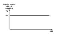
図14は、非特許文献3に記載のKBPにおける、busy poll threadが使用するCPU使用率を示す図である。
図14に示すように、KBPでは、kernel threadはbusy pollを行うために、CPUコアを専有する。図13に示す間欠的なパケット受信であっても、KBPでは、パケット到着有無に関わらず常にCPUを使用するため、消費電力が大きくなる課題がある。 FIG. 14 is a diagram showing the CPU utilization rate used by the busy poll thread in the KBP described in Non-Patent Document 3.
As shown in Fig. 14, in KBP, the kernel thread occupies a CPU core in order to perform busy poll. Even in the case of intermittent packet reception as shown in Fig. 13, the KBP always uses the CPU regardless of whether a packet has arrived, which causes a problem of increased power consumption.
このような背景を鑑みて本発明がなされたのであり、本発明は、消費電力の低減を図りつつ、APLを改変することなく、サーバ内の遅延を小さくしてパケット転送を行うことを課題とする。The present invention was made in light of this background, and aims to reduce power consumption while minimizing delays within the server and forwarding packets without modifying the APL.
前記した課題を解決するため、サーバ内遅延制御装置であって、OSが、カーネルと、前記OSを備えるサーバ中のメモリ空間で、前記カーネルが管理するリングバッファと、インターフェイス部からのハードウェア割込がどのデバイスのものであるかを示すネットデバイスの情報を登録するポールリストと、を有し、前記カーネル内に、ポーリングモデルを用いてパケット到着を監視するスレッドを立ち上げる前記サーバ内遅延制御装置を備えており、前記サーバ内遅延制御装置は、前記ポールリストを監視するパケット到着監視部と、パケットが到着している場合は、前記リングバッファに保持したパケットを参照し、次に行う処理に基づいて該当するキューのエントリを前記リングバッファから削除する刈取りを実行するパケット刈取部と、パケットが所定期間到着しない場合は前記スレッドをスリープさせ、かつ、パケット到着時はハードウェア割込により当該スレッドのスリープ解除を行うスリープ管理部と、を備えることを特徴とするサーバ内遅延制御装置とした。To solve the above problem, an intra-server delay control device is provided, in which an OS has a kernel, a ring buffer managed by the kernel in the memory space of a server equipped with the OS, and a poll list that registers information on network devices indicating which device a hardware interrupt from an interface unit is for, and the intra-server delay control device is provided in the kernel, which starts a thread that monitors packet arrivals using a polling model, and the intra-server delay control device is characterized in that it has a packet arrival monitoring unit that monitors the poll list, a packet reaping unit that, if a packet has arrived, refers to the packet held in the ring buffer and performs reaping to delete the corresponding queue entry from the ring buffer based on the next process to be performed, and a sleep management unit that puts the thread to sleep if no packet arrives for a specified period of time, and wakes up the thread by a hardware interrupt when a packet arrives.
本発明によれば、消費電力の低減を図りつつ、APLを改変することなく、サーバ内の遅延を小さくしてパケット転送を行うことができる。According to the present invention, it is possible to reduce power consumption and transfer packets with reduced delays within the server without modifying the APL.
以下、図面を参照して本発明を実施するための形態(以下、「本実施形態」という)におけるサーバ内遅延制御システム等について説明する。
[概要]
図1は、本発明の実施形態に係るサーバ内遅延制御システムの概略構成図である。本実施形態は、Linux kernel 2.5/2.6より実装されているNew API(NAPI)によるRx側パケット処理に適用した例である。図11と同一構成部分には、同一符号を付している。
図1に示すように、サーバ内遅延制御システム1000は、OS70(例えば、Host OS)を備えるサーバ上で、ユーザが使用可能なuser space60に配置されたパケット処理APL1を実行し、OS70に接続されたHW10のNIC11とパケット処理APL1との間でパケット転送を行う。 Hereinafter, an intra-server delay control system and the like in an embodiment for carrying out the present invention (hereinafter, referred to as "the present embodiment") will be described with reference to the drawings.
[overview]
Fig. 1 is a schematic diagram of a server delay control system according to an embodiment of the present invention. This embodiment is an example of application to Rx-side packet processing using New API (NAPI) implemented in Linux kernel 2.5/2.6. The same components as those in Fig. 11 are given the same reference numerals.
As shown in FIG. 1, the intra-server delay control system 1000 executes a packet processing APL1 placed in a
OS70は、kernel171、Ring Buffer72、およびDriver73を有し、kernel171は、サーバ内遅延制御装置100およびプロトコル処理部74を有する。The
本実施形態では、kernel171が、サーバ内遅延制御装置100を備える関係で、図11に示すkernel71と区別して新たな番号を付している。kernel171は、サーバ内遅延制御装置100が設置されている以外は、図11に示すkernel71と同一機能である。ただし、kernel171は、livepatch(後記)を用いることで、既存のkernel71(図11参照)を改造(新しくビルド)することなく、実現が可能である。In this embodiment, kernel 171 is given a new number to distinguish it from
kernel171は、OS70(例えば、Host OS)の基幹部分の機能であり、ハードウェアの監視やプログラムの実行状態をプロセス単位で管理する。ここでは、kernel171は、パケット処理APL1からの要求に応えるとともに、HW10からの要求をパケット処理APL1に伝える。kernel171は、パケット処理APL1からの要求に対して、システムコールを介することで処理する。
kernel171は、Socket75を介して、パケット処理APL1へパケットを送信する。Kernel71は、Socket75を介してパケット処理APL1からパケットを受信する。 The kernel 171 is a core function of the OS 70 (for example, a host OS) and monitors hardware and manages the execution state of programs on a process-by-process basis. Here, the kernel 171 responds to requests from the packet processing APL1 and transmits requests from the
The kernel 171 transmits a packet to the
Ring Buffer72は、サーバの中にあるメモリ空間においてkernel171が管理する。Ring Buffer72は、kernel171が出力するメッセージをログとして格納する一定サイズのバッファであり、上限サイズを超過すると先頭から上書きされる。
Driver73は、kernel171でハードウェアの監視を行うためデバイスドライバである。Driver73 is a device driver that monitors the hardware in kernel171.
プロトコル処理部74は、OSI参照モデルが定義するL2/L3/L4のプロトコル処理を行う。The protocol processing unit 74 performs protocol processing for L2/L3/L4 defined by the OSI reference model.
Socket75は、kernel171がプロセス間通信を行うためのインターフェイスである。Socket75は、ソケットバッファを有し、データのコピー処理を頻繁に発生させない。Socket 75 is an interface that kernel 171 uses for inter-process communication. Socket 75 has a socket buffer and does not frequently copy data.
<サーバ内遅延制御装置>
サーバ内遅延制御装置100は、パケット到着監視部110と、パケット刈取部120と、sleep管理部130と、CPU周波数/CPU idle設定部140(CPU周波数設定部,CPUアイドル設定部)と、を備える。 <Internal server delay control device>
The intra-server
パケット到着監視部110は、パケットが到着していないかを監視するためのthreadである。パケット到着監視部110は、poll_list186(図2参照)を監視(polling)する。The packet arrival monitor unit 110 is a thread that monitors whether packets have arrived. The packet arrival monitor unit 110 monitors (polls) the poll_list 186 (see Figure 2).
パケット到着監視部110は、poll_list186からRing_Buffer72(図2参照)にパケットが存在するポインタ情報と、net_device情報とを取得し、パケット刈取部120へ当該情報(ポインタ情報およびnet_device情報)を伝達する。ここで、poll_list186に複数パケット情報が存在する場合は、複数分当該情報を伝達する。The packet arrival monitoring unit 110 obtains the pointer information indicating that a packet exists in the Ring_Buffer 72 (see FIG. 2) and the net_device information from the poll_list 186, and transmits the information (pointer information and net_device information) to the packet harvesting unit 120. Here, if multiple packet information exists in the poll_list 186, the multiple pieces of information are transmitted.
パケット刈取部120は、パケットが到着している場合は、Ring Buffer72に保持したパケットを参照し、次に行う処理に基づいて該当するキューのエントリをRing Buffer72から削除する刈取りを実行する(以下、単にRing Buffer72からパケットを刈取るという場合がある)。パケット刈取部120は、受信した情報をもとにRing_Buffer72からパケットを取り出し、netif_receive_skb87へパケットを伝達する。When a packet has arrived, the packet reaping unit 120 refers to the packet stored in the
sleep管理部130は、パケットが所定期間到着しない場合はスレッド(polling thread)をスリープ(sleep)させ、かつ、パケット到着時はこのスレッド(polling thread)のハードウェア割込(hardIRQ)によりスリープ解除を行う(詳細後記)。The sleep management unit 130 puts the polling thread to sleep if no packets arrive for a specified period of time, and wakes up the polling thread using a hardware interrupt (hardIRQ) when a packet arrives (details below).
CPU周波数/CPU idle設定部140は、スリープ中に、スレッド(polling thread)が使用するCPUコアのCPU動作周波数を低く設定する。CPU周波数/CPU idle設定部140は、スリープ中に、このスレッド(polling thread)が使用するCPUコアのCPUアイドル(CPU idle)状態を省電力モードに設定する(詳細後記)。The CPU frequency/CPU idle setting unit 140 sets the CPU operating frequency of the CPU core used by the thread (polling thread) to a low value during sleep. The CPU frequency/CPU idle setting unit 140 sets the CPU idle state of the CPU core used by this thread (polling thread) to a power saving mode during sleep (details described later).
図2は、図1のサーバ内遅延制御システム1000のNew API(NAPI)によるRx側パケット処理の詳細を説明する図である。図1および図12と同一構成部分には、同一符号を付している。
<Device driver>
図2に示すように、Device driverには、ネットワークインターフェースカードであるNIC11、NIC11の処理要求の発生によって呼び出され要求された処理(ハードウェア割込)を実行するハンドラであるhardIRQ81、およびソフトウェア割込の処理機能部であるnetif_rx182が配置される。 Fig. 2 is a diagram for explaining details of Rx-side packet processing by New API (NAPI) of the intra-server delay control system 1000 in Fig. 1. The same components as those in Fig. 1 and Fig. 12 are given the same reference numerals.
<Device driver>
As shown in FIG. 2, the device driver includes a
<Networking layer>
Networking layerには、NIC11からのハードウェア割込がどのデバイスのものであるかを示すネットデバイス(net_device)の情報を登録するpoll_list186、パケット到着監視部110、キューを刈取ったパケットを、割込の発生しないソケット通信のためのsk_buff構造体(kernel171が、パケットの状態を示す構造体)を作成するnetif_receive_skb87、およびRing Buffer72が配置される。 <Networking layer>
The networking layer includes a poll_list 186 that registers information on the net device (net_device) indicating which device the hardware interrupt from the
<Protocol layer>
Protocol layerには、パケット処理機能部であるip_rcv88、arp_rcv89等が配置される。なお、プロトコル処理は、ip_rcv88、arp_rcv89以外にもある。 <Protocol layer>
In the protocol layer, packet processing function units such as ip_rcv 88 and arp_rcv 89 are arranged. Note that there are other protocol processes in addition to ip_rcv 88 and arp_rcv 89.
上記netif_rx182、netif_receive_skb87、ip_rcv88、およびarp_rcv89は、Kernel171の中でパケット処理のために呼ばれるプログラムの部品(関数の名称)である。The above netif_rx 182, netif_receive_skb 87, ip_rcv 88, and arp_rcv 89 are program components (function names) called for packet processing within Kernel 171.
以下、サーバ内遅延制御システム1000の動作を説明する。
[本発明によるRx側パケット処理動作]
図2の矢印(符号)d~g,k~oは、Rx側パケット処理の流れを示している。
NIC11が、対向装置からフレーム内にパケット(またはフレーム)を受信すると、DMA転送によりCPUを使用せずに、Ring Buffer72へ到着したパケットをコピーする(図2の符号d参照)。このRing Buffer72は、サーバ中のメモリ空間で、Kernel171(図1参照)が管理している。 The operation of the intra-server delay control system 1000 will now be described.
[Rx-side packet processing operation according to the present invention]
The arrows (symbols) d to g and ko in FIG. 2 indicate the flow of packet processing on the Rx side.
When the
NIC11は、パケットが到着すると、ハードウェア割込(hardIRQ)をhardIRQ81(ハンドラ)に立ち上げ(図2の符号e参照)、netif_rx182が下記の処理を実行することで、Kernel171は、当該パケットを認知する。When a packet arrives, the
netif_rx182は、hardwire81(ハンドラ)が立ち上がると(図2の符号f参照)、poll_list186に、ハードウェア割込(hardIRQ)の中身の情報の1つである、NIC11からのハードウェア割込がどのデバイスのものであるかを示すネットデバイス(net_device)の情報を保存して、キューの刈取り情報を登録する(図2の符号g参照)。具体的には、netif_rx182は、Ring Buffer72にパケットが詰め込まれたことを受けて、NIC11のドライバを使って、以後のキューの刈取りをpoll_list186に登録する(図2の符号g参照)。これにより、poll_list186には、Ring Buffer72にパケットが詰め込まれたことによる、キューの刈取りが登録される。When hardwire 81 (handler) is started (see symbol f in Figure 2), netif_rx 182 saves net device (net_device) information, which is one of the pieces of information contained in the hardware interrupt (hardIRQ), indicating which device the hardware interrupt from
netif_rx182は、poll_list186にnet_deviceを登録するが、図12のnetif_rx82とは異なり、ソフトウェア割込(softIRQ)のスケジューリングは行わない。すなわち、netif_rx182は、ソフトウェア割込(softIRQ)のスケジューリングは行わない点で、図12のnetif_rx82とは異なる。Netif_rx 182 registers net_device in poll_list 186, but unlike netif_rx 82 in FIG. 12, it does not schedule software interrupts (softIRQs). In other words, netif_rx 182 differs from netif_rx 82 in FIG. 12 in that it does not schedule software interrupts (softIRQs).
また、netif_rx182は、sleepしているpolling threadを呼び起こすsleep解除を行う(図2の符号p参照)。本実施形態は、非特許文献3に記載のKBPに対し、このpolling threadの呼び起こし処理(sleep解除)を追加している。
ここまでで、図2の<Device driver>におけるハードウェア割込の処理は停止する。 In addition, the netif_rx 182 performs sleep release to wake up a sleeping polling thread (see symbol p in FIG. 2). In this embodiment, this polling thread wake-up process (sleep release) is added to the KBP described in Non-Patent Document 3.
At this point, the hardware interrupt processing in the <Device driver> in FIG. 2 stops.
本実施形態では、図12に示す<Networking layer>において、softIRQ83およびdo_softirq84が削除され、これに伴い、図12に示すnetif_rx82が、softIRQ83(ハンドラ)を立ち上げる通知(図12の符号h参照)も行わない。In this embodiment, softIRQ 83 and do_softirq 84 are deleted from the <Networking layer> shown in FIG. 12, and as a result, netif_rx 82 shown in FIG. 12 does not notify to launch softIRQ 83 (handler) (see symbol h in FIG. 12).
本実施形態では、サーバ内遅延制御システム1000は、図12に示すsoftIRQ83およびdo_softirq84を削除し、代わりに図2に示す<Networking layer>のサーバの中にあるメモリ空間に、サーバ内遅延制御装置100を設ける。In this embodiment, the intra-server delay control system 1000 removes the softIRQ 83 and do_softirq 84 shown in FIG. 12, and instead provides an intra-server
図2に示す<Networking layer>において、サーバ内遅延制御装置100のパケット到着監視部110は、poll_list186を監視(polling)し(図2の符号k参照)、パケット到着有無を確認する。In the <Networking layer> shown in FIG. 2, the packet arrival monitoring unit 110 of the server
パケット到着監視部110は、poll_list186から、Ring_Buffer72にパケットが存在するポインタ情報と、net_device情報とを取得し、パケット刈取部120へ当該情報(ポインタ情報およびnet_device情報)を伝達する(図2の符号q参照)。ここで、poll_list186に複数パケット情報が存在する場合は、複数分当該情報を伝達する。The packet arrival monitoring unit 110 obtains the pointer information indicating that a packet exists in the
サーバ内遅延制御装置100のパケット刈取部120は、パケットが到着している場合は、Ring Buffer72からパケットを刈取る(図2の符号l参照)。
パケット刈取部120は、受信した情報をもとにRing_Buffer72からパケットを取り出し、netif_receive_skb87へパケットを伝達する(図2の符号m参照)。 If a packet has arrived, the packet reaper 120 of the intra-server
The packet harvesting unit 120 extracts the packet from the
このように、サーバ内遅延制御システム1000は、NW遅延発生の主要因であるパケット処理のsoftIRQを停止し、サーバ内遅延制御装置100のパケット到着監視部110がパケット到着を監視するpolling threadを実行する。そして、パケット刈取部120が、パケット到着時に、pollingモデル(softIRQなし)によりパケット処理を行う。In this way, the intra-server delay control system 1000 stops the softIRQ for packet processing, which is the main cause of network delays, and the packet arrival monitor 110 of the intra-server
すなわち、サーバ内遅延制御装置100におけるpolling threadは、kernel threadとして動作し、pollingモードでパケット到着を監視する。パケット到着監視部110は、poll_list186を監視する。パケット刈取部120は、パケット到着時にRing Buffer72からパケットを取り出し、netif_receive_skb87へパケットを転送する。That is, the polling thread in the intra-server
パケット到着時は、ハード割込ハンドラでpolling threadを起こすことで、softIRQ競合を回避して、即時にパケット転送処理が可能となる。言い換えれば、kernel threadとしてパケット到着監視機能を待機させておき、ハード割込で起こすことで、NAPI等のソフト割込によるパケット転送処理よりも低遅延化が可能になる。When a packet arrives, a polling thread is woken up by the hardware interrupt handler, which avoids softIRQ contention and enables immediate packet forwarding. In other words, by having the packet arrival monitoring function wait as a kernel thread and waking it up with a hardware interrupt, it is possible to achieve lower latency than packet forwarding using soft interrupts such as NAPI.
パケット到着を監視するkernel threadは、パケット到着がない間はsleep可能とする。
上記polling threadは、パケット到着有無に応じてsleepし、パケット到着時はhardIRQ81によりsleep解除を行う。具体的には、サーバ内遅延制御装置100のsleep管理部130は、パケット到着有無に応じて、すなわち一定期間パケットの到着がないと、polling threadをsleepさせる。sleep管理部130は、パケット到着時はhardIRQ81によりsleep解除を行う。これにより、softIRQ競合を回避して、低遅延化を実現する。 The kernel thread that monitors packet arrival is allowed to sleep while no packets arrive.
The polling thread goes to sleep depending on whether a packet has arrived, and is released from sleep by hardIRQ 81 when a packet arrives. Specifically, the sleep management unit 130 of the intra-server
サーバ内遅延制御装置100のCPU周波数/CPU idle設定部140は、パケット到着有無に応じてCPU動作周波数やidle設定を変更する。具体的には、CPU周波数/CPU idle設定部140は、sleep時はCPU周波数を下げ、再度起動時はCPU周波数を高める(CPU動作周波数をもとに戻す)。また、CPU周波数/CPU idle設定部140は、sleep時はCPU idle設定を省電力に変更する。sleep時にCPU動作周波数を低く変更する、また、CPU idle設定を省電力に変更することで省電力化も達成する。The CPU frequency/CPU idle setting unit 140 of the intra-server
netif_receive_skb87は、sk_buff構造体を作り、パケットの内容を解析し、タイプ毎に後段のプロトコル処理部74(図11参照)へ処理をまわす。すなわち、netif_receive_skb87は、パケットの中身を解析し、パケットの中身に応じて処理をする場合には、<Protocol layer>のip_rcv88に処理を回し、また、例えばL2であればarp_rcv89に処理をまわす。The netif_receive_skb 87 creates an sk_buff structure, analyzes the contents of the packet, and passes the processing to the downstream protocol processing unit 74 (see FIG. 11) for each type. That is, the netif_receive_skb 87 analyzes the contents of the packet, and if processing is to be performed according to the contents of the packet, passes the processing to the ip_rcv 88 of the <Protocol layer>, or, for example, to arp_rcv 89 if it is L2.
図3は、サーバ内遅延制御装置100のpolling thread動作例を示す図である。縦軸は、polling threadが使用するCPUコアのCPU使用率[%]を示し、横軸は、時間を示す。なお、図3は、図13に示す間欠的にパケットが受信される映像(30FPS)のデータ転送例に対応するパケット到着によるpolling thread動作例を示している。
図3に示すように、サーバ内遅延制御装置100のsleep管理部130は、一定期間パケットの到着がない場合(より詳細には、あるパケット到着してから、保守・運用者があらかじめ定めた固定値(一定期間)を経過しても次のパケット到着がない場合)に、polling threadをsleepさせる(図3の符号s参照)。そして、sleep管理部130は、パケット到着のhardIRQ81でpolling threadを起動させる(図3の符号t参照)。
なお、sleep 時には、kernelthreadがCPUコアを専有していないため、polling threadが使用する以外にも、システム安定動作のためのタイマの割込みが該当CPUコアに入ったり、エラー処理等のためのmigration threadが該当CPUコアに入ったりすることで、polling threadが使用するCPUコアのCPU使用率が変動する場合がある(図3の符号u参照)。 3 is a diagram showing an example of the operation of a polling thread in the intra-server
As shown in Fig. 3, the sleep management unit 130 of the intra-server
During sleep, the kernel thread does not have exclusive use of the CPU core. Therefore, in addition to the polling thread, a timer interrupt for stable system operation may enter the corresponding CPU core, or a migration thread for error processing, etc. may enter the corresponding CPU core, which may cause the CPU utilization of the CPU core used by the polling thread to fluctuate (see symbol u in Figure 3).
[live patchによる登録動作]
次に、live patchによる登録動作について説明する。
サーバ内遅延制御システム1000(図1参照)は、図1に示すOS70のkernel171が、サーバ内遅延制御装置100を備える。kernel171は、livepatchを用いることで、既存のkernel71(図11参照)を改造(新しくビルド)することなく、実現が可能になる。以下、kernel171に適用されるlivepatchについて説明する。[Registration operation by live patch]
Next, the registration operation by live patch will be described.
In the intra-server delay control system 1000 (see FIG. 1), the kernel 171 of the
livepatchは、Linux(登録商標)kernelに適用されるカーネルパッチ機能である。livepatchを使うことで、システムを再起動することなくカーネル空間に即座に修正を適用することができる。すなわち、
(1)livepatchは、netif_rx182(図2参照)のsoftIRQスケジューリング機能を抑制する。 livepatch is a kernel patch function applied to the Linux (registered trademark) kernel. By using livepatch, you can instantly apply modifications to the kernel space without rebooting the system. That is,
(1) livepatch suppresses the softIRQ scheduling function of netif_rx 182 (see Figure 2).
(2)livepatchは、パケット到着監視を行うthread(パケット到着監視部110、具体的にはisol_net_rx)を起動する。起動する際、他プロセスやkernel threadにbusy poll(図2の符号k参照)の邪魔をされないように、thread(パケット到着監視部110)は、CPUコアを専有する。そのために、当該threadはリアルタイムプロセス等の高優先設定を割り当てる。トラヒックフロー数(または、トラヒック量)に応じて、複数CPUコア上でthreadを起動し、監視するpoll_list186(図2参照)を割り当てる。これにより、トラヒックフロー(トラヒック量)に応じたスケールアウトが可能になる。
以降、図2に示すパケット処理の動作が実行される。 (2) Livepatch starts a thread (packet arrival monitor 110, specifically isol_net_rx) that monitors packet arrival. When starting, the thread (packet arrival monitor 110) occupies a CPU core so that it is not interrupted by busy poll (see symbol k in FIG. 2) from other processes or kernel threads. For this reason, the thread is assigned a high priority setting such as a real-time process. Depending on the number of traffic flows (or traffic volume), threads are started on multiple CPU cores and a poll_list 186 (see FIG. 2) to be monitored is assigned. This makes it possible to scale out according to the traffic flow (traffic volume).
Thereafter, the packet processing operation shown in FIG. 2 is executed.
[サーバ内遅延制御装置100のRx側パケット処理動作フロー]
図4は、サーバ内遅延制御装置100(図2参照)のRx側動作および省電力化のための管理処理を示すフローチャートである。図2を参照してRx側動作を説明する。
polling threadが起動している間は、本動作フローをループして実行する。
ステップS1では、サーバ内遅延制御装置100のパケット到着監視部110(図2参照)は、poll_list186(図2参照)をCPUを専有して監視(poll)し(図2の符号k参照)、パケット到着有無を確認する。[Rx side packet processing operation flow of the server delay control device 100]
4 is a flowchart showing the Rx side operation and power saving management process of the intra-server delay control device 100 (see FIG. 2). The Rx side operation will be described with reference to FIG.
While the polling thread is running, this operation flow is executed in a loop.
In step S1, the packet arrival monitor 110 (see FIG. 2) of the intra-server
ステップS2では、パケット到着監視部110(図2参照)は、poll list186にパケット到着を意味するポインタ情報があるか否かを判別する。
poll list186にパケット到着を意味するポインタ情報がある場合(S2:Yes)、ステップS3に進み、poll list186にパケット到着を意味するポインタ情報がない場合(S2:No)、ステップS1の処理に戻る。 In step S2, the packet arrival monitor 110 (see FIG. 2) determines whether or not the poll list 186 contains pointer information indicating the arrival of a packet.
If the poll list 186 contains pointer information indicating that a packet has arrived (S2: Yes), the process proceeds to step S3. If the poll list 186 contains no pointer information indicating that a packet has arrived (S2: No), the process returns to step S1.
ステップS3では、パケット到着監視部110は、poll_list186からRing_Buffer72(図2参照)にパケットが存在するポインタ情報と、NET_DEVICE情報とを取得し、パケット刈取部120へ当該情報(ポインタ情報およびNET_DEVICE情報)を伝達する(図2の符号q参照)。ここで、poll_list186に複数パケット情報が存在する場合は、複数分当該情報を伝達する。In step S3, the packet arrival monitoring unit 110 obtains the pointer information indicating that a packet exists in the Ring_Buffer 72 (see FIG. 2) and the NET_DEVICE information from the poll_list 186, and transmits the information (pointer information and NET_DEVICE information) to the packet harvesting unit 120 (see symbol q in FIG. 2). Here, if multiple packet information exists in the poll_list 186, multiple pieces of the information are transmitted.
ステップS4では、サーバ内遅延制御装置100のパケット刈取部120(図2参照)は、パケットが到着している場合は、Ring Buffer72に保持したパケットを参照し、次に行う処理に基づいて該当するキューのエントリをRing Buffer72から削除する刈取りを実行する(図2の符号l参照)。In step S4, if a packet has arrived, the packet reaping unit 120 (see FIG. 2) of the intra-server
ステップS5では、パケット刈取部120は、受信した情報をもとにRing_Buffer72からパケットを取り出し、netif_receive_skb87へパケットを伝達する(図2の符号m参照)。In step S5, the packet harvesting unit 120 extracts the packet from the
ステップS6では、サーバ内遅延制御装置100のsleep管理部130は、一定期間を経過してもpoll_list186にパケットの格納がない(パケット到着がない)ことを判別する。
一定期間を経過してもpoll_list186にパケットの格納がない場合(S6:Yes)、ステップS7でsleep管理部130は、polling threadをsleepに落とす(スリープさせる)。poll_list186にパケットの格納がある場合(S6:No)、ステップS1に戻る。 In step S6, the sleep management unit 130 of the intra-server
If no packets are stored in the poll_list 186 after a certain period of time has elapsed (S6: Yes), the sleep management unit 130 puts the polling thread into sleep (puts it to sleep) in step S7. If packets are stored in the poll_list 186 (S6: No), the process returns to step S1.
ステップS8では、CPU周波数/CPU idle設定部140は、polling threadが使用するCPUコアの動作周波数を低く設定して本フローの処理を終える。CPU周波数/CPU idle設定部140は、CPU idle設定もできる場合は、有効化する。In step S8, the CPU frequency/CPU idle setting unit 140 sets the operating frequency of the CPU core used by the polling thread to a low value and ends the processing of this flow. If the CPU frequency/CPU idle setting unit 140 can also set the CPU idle, it enables it.
図5は、サーバ内遅延制御装置100の省電力化のためのCPU周波数/CPU idle設定処理を示すフローチャートである。
ステップS11において、パケット到着時に起動されるハード割込処理部(図2のnetif_rx182)は、パケット到着時にpolling thread(図2のサーバ内遅延制御装置100)を起動する。既にpolling threadが起動している場合はそのまま継続する。sleep管理部130は、パケット到着時のhardIRQによりsleep解除を行う。 FIG. 5 is a flowchart showing a CPU frequency/CPU idle setting process for power saving in the intra-server
In step S11, the hardware interrupt processing unit (netif_rx 182 in FIG. 2), which is started when a packet arrives, starts a polling thread (internal server
ステップS12において、CPU周波数/CPU idle設定部140は、polling threadが使用するCPUコアの動作周波数を高く(CPUコアの動作周波数をもとに戻す)設定して本フローの処理を終了する。ここで、CPU周波数/CPU idle設定部140は、CPU idel設定も変更している場合はもとに戻す。In step S12, the CPU frequency/CPU idle setting unit 140 sets the operating frequency of the CPU core used by the polling thread to a high frequency (returning the operating frequency of the CPU core to its original frequency), and ends the processing of this flow. Here, if the CPU frequency/CPU idle setting unit 140 has also changed the CPU idle setting, it returns it to its original frequency.
<付加機能>
poll_list186からのパケット刈り取り漏れを防ぐために、polling threadを定期的に起動し、poll_list186のパケット到着有無を確認してもよい。
このようにすることで、NIC11によるパケット到着と、polling threadのsleepが同時に発生する等のタイミング問題があった場合に、poll_list186にパケットが残ることを防止することができる。 <Additional features>
In order to prevent packets from being missed from the poll_list 186, a polling thread may be periodically started to check whether or not a packet has arrived in the poll_list 186.
In this way, if there is a timing problem such as the arrival of a packet by the
[本実施形態と既存技術との差異]
次に、本実施形態と既存技術(図12参照)との差異について説明する。[Difference between this embodiment and existing technology]
Next, the difference between this embodiment and the existing technology (see FIG. 12) will be described.
<背景>
一般に、ハードウェア割込(hardIRQ)は、優先度が高く、該当CPUの処理を中断し、hardIRQの処理を最優先で処理する必要がある。このため、オーバーヘッドが大きい。そのため、hardIRQでは、パケット到着を知らせるのみとし、パケット処理は、softIRQで処理する設計思想となっている(「kernelの原則」という)。ここで、softIRQは、他のsoftIRQと競合し、待たされる事象が発生する(遅延発生の要因となる)。
従来技術が割込モデルにしている理由は、かつてはCPUリソースが限られていた(または、Raspberry PiのようなSingle board ComputerのようにCPUコアが少ないデバイスでも動作させる)ために、1つのCPUコアを他の処理と共有して使用する設計思想になっていたためである。この場合、通常の処理や割込処理等でCPUタイムを切り替えながら処理を行う。上記割込処理であっても、softIRQは競合することになり、待ち時間が発生する。
なお、softIRQのスケジューリングを行うスケジューラであるksoftirqdは、softIRQの種別に応じて優先度を付与する機能を具備しておらず、この競合による遅延発生は抑制できない。 <Background>
Generally, hardware interrupts (hardIRQs) have a high priority, and the processing of the relevant CPU must be interrupted and the hardIRQ processing must be given top priority. This creates a large overhead. For this reason, the design philosophy is that hardIRQs only notify the arrival of packets, and packet processing is handled by softIRQs (this is called the "kernel principle"). However, softIRQs compete with other softIRQs, causing events that require waiting (which causes delays).
The reason why conventional technology uses the interrupt model is that in the past, CPU resources were limited (or devices with few CPU cores, such as single board computers like the Raspberry Pi, were designed to share one CPU core with other processes). In this case, processing is performed by switching CPU time between normal processing and interrupt processing. Even with the above interrupt processing, softIRQs will compete, causing waiting times.
In addition, ksoftirqd, the scheduler that schedules softIRQs, does not have the functionality to assign priorities according to the type of softIRQ, and so cannot suppress delays caused by this contention.
<既存技術(図12参照)>
図12に示すように、kernel71(図11)は、NIC11からのパケット到着の知らせを、hardIRQ81により受け取り(図12の符号h参照)、パケット処理のためのsoftIRQ83をスケジューリングする(図12の破線囲みp参照)。この際、他の割込処理と競合すると待合せが発生し、msオーダのNW遅延が発生する。 <Existing technology (see Figure 12)>
12, the kernel 71 (FIG. 11) receives notification of the arrival of a packet from the
<サーバ内遅延制御システム1000(図2参照)>
・パケット到着監視部110およびパケット刈取部120の実装
図2に示すように、サーバ内遅延制御システム1000は、<Networking layer>において、netif_rx182は、poll_list186にnet_deviceを登録するが、既存技術(図12参照)のnetif_rx82とは異なり、ソフトウェア割込(softIRQ)のスケジューリングは行わない(「変更点1」)。 <In-server delay control system 1000 (see FIG. 2)>
Implementation of packet arrival monitoring unit 110 and packet reaping unit 120 As shown in FIG. 2, in the <Networking layer> of the server delay control system 1000, netif_rx 182 registers net_device in poll_list 186, but unlike netif_rx 82 in the existing technology (see FIG. 12), does not schedule software interrupts (softIRQ) ("
図2に示すように、サーバ内遅延制御システム1000は、<Networking layer>のサーバの中にあるメモリ空間に、サーバ内遅延制御装置100を設ける(「変更点2」)。
サーバ内遅延制御装置100のパケット到着監視部110は、poll_list186を常に監視(busy poll)し(図2の符号k参照)、パケット到着有無を確認する。 As shown in FIG. 2, the intra-server delay control system 1000 provides an intra-server
The packet arrival monitor 110 of the intra-server
パケット到着監視部110は、poll_list186からRing_Buffer72にパケットが存在するポインタ情報と、NET_DEVICE情報とを取得し、パケット刈取部120へ当該情報(ポインタ情報およびNET_DEVICE情報)を伝達する(図2の符号q参照)。The packet arrival monitoring unit 110 obtains the pointer information indicating that a packet exists in the
サーバ内遅延制御装置100のパケット刈取部120は、パケットが到着している場合は、Ring Buffer72からパケットを刈取る(図2の符号l参照)。If a packet has arrived, the packet harvesting unit 120 of the server
パケット刈取部120は、受信した情報をもとにRing_Buffer72からパケットを取り出し、netif_receive_skb87へパケットを伝達する(図2の符号m参照)。The packet harvesting unit 120 extracts the packet from the
上記「変更点1」による作用効果は、下記の通りである。
まず、本実施形態では、ハードウェア割込(hardIRQ)によるパケット到着の通知については、NAPIを踏襲する。softIRQは、CPUリソースを有効活用する点では便利であるが、パケットの即時転送の観点では適さない。そのため、本実施形態では、softIRQの機能を停止し、kernelの中でpollingモデルを実現する点が新しい。具体的には、図2に示すnetif_rx182が、図12に示すnetif_rx82のように、softIRQ83(ハンドラ)を立ち上げる通知(図12の符号h参照)を行わないことに示されている。 The effects of the above "
First, in this embodiment, the notification of packet arrival by hardware interrupt (hardIRQ) follows NAPI. SoftIRQ is convenient in terms of effective use of CPU resources, but is not suitable from the viewpoint of immediate packet transfer. Therefore, in this embodiment, the function of softIRQ is stopped and a polling model is realized in the kernel. Specifically, it is shown that netif_rx 182 shown in FIG. 2 does not notify softIRQ 83 (handler) to start up (see symbol h in FIG. 12) like netif_rx 82 shown in FIG. 12.
なお、pollingモデルについては、ユーザスペースからpollingを行うDPDKが既存技術としてある(図10参照)。しかしながら、DPDKは、APLからpollingを行うため、APLに改変が必要である。As for the polling model, DPDK, which performs polling from user space, is an existing technology (see Figure 10). However, since DPDK performs polling from the APL, modifications to the APL are required.
上記「変更点2」による作用効果は、下記の通りである。
本実施形態は、図1に示すkernel171の中でpolling専用のthread(サーバ内遅延制御装置100のパケット到着監視部110)を起動し、サーバ内遅延制御装置100のパケット刈取部120が、パケット到着時に、pollingモデル(softIRQなし)によりパケット処理を行う。これにより、APL改変不要になる、換言すれば、既存のPOSIX socket APIを利用することが可能になる。 The effects of the above "
In this embodiment, a polling-only thread (the packet arrival monitor 110 of the intra-server delay control device 100) is started in the kernel 171 shown in Fig. 1, and the packet harvester 120 of the intra-server
また、前述threadが他のsoftIRQなどにCPUタイムを奪われないようにするために、上記[live patchによる登録]で述べたように、thread起動時にCPUコアを専有し、高優先設定を行うことで、pollingの邪魔をさせない。Also, to prevent the aforementioned thread from having CPU time taken over by other softIRQs, as described above in [Registration by live patch], the thread occupies a CPU core when it is started and is set to high priority so that it does not interfere with polling.
以上、サーバ内遅延制御装置100は、パケット到着監視部110およびパケット刈取部120を備えることで、低遅延なパケット転送を実現する。すなわち、パケット到着時のソフトウェア割込(softIRQ)を停止し、kernel内でpollingモデルを実現する。パケット到着を監視するkernel threadを新たに作り、poll_list186へのパケット到着を監視する。これにより、パケット到着時は、待合せなく即時に刈り取られるため、低遅延なパケット処理を実現できる。As described above, the intra-server
・sleep管理部130およびCPU周波数/CPU idle設定部140の実装
サーバ内遅延制御装置100は、さらに、sleep管理部130およびCPU周波数/CPU idle設定部140を備えることで、上述した低遅延なパケット処理に加え、省電力を図る。すなわち、パケット到着を監視するkernel threadは、パケット到着がない間はsleep可能とする。sleep中のthreadは、パケット到着時のhardIRQハンドラで起こすことで、softIRQ競合を回避しながら即時起動する。CPU動作周波数やCPU idle状態を、上記sleepに合わせて調整することで更に低消費電力化を図る。Implementation of sleep management unit 130 and CPU frequency/CPU idle setting unit 140 The intra-server
< sleep管理部130およびCPU周波数/CPU idle設定部140の詳細動作(図2参照)>
図2に示すnetif_rx182は、パケット到着時にpolling threadがsleepしている場合に起動する(図2の符号p参照)。既にpolling threadが起動している場合は、特に何も動作せずにハードウェア割込ハンドラを終了する。 <Detailed Operation of the Sleep Management Unit 130 and the CPU Frequency/CPU Idle Setting Unit 140 (see FIG. 2)>
2 is started if the polling thread is sleeping when a packet arrives (see symbol p in FIG. 2). If the polling thread is already running, the hardware interrupt handler ends without performing any particular operation.
ハードウェア割込ハンドラにより起動されたpolling thread(サーバ内遅延制御装置100)のCPU周波数/CPU idle設定部140は、polling threadが使用するCPUコアのCPU動作周波数を高く(CPUコアの動作周波数をもとに戻す)設定する。
ここで、kernelは、CPUコアの動作周波数をgovernor設定により変更が可能であり、CPU周波数/CPU idle設定部140は、governor設定等を利用して、CPU動作周波数を高く設定することができる。ただし、CPU idle設定は、CPU機種依存するものである。なお、CPUコアがCPU idle設定を有効化している場合は、解除することも可能である。 The CPU frequency/CPU idle setting unit 140 of the polling thread (intra-server delay control device 100) started by the hardware interrupt handler sets the CPU operating frequency of the CPU core used by the polling thread to a higher value (returning the operating frequency of the CPU core to its original value).
Here, the kernel can change the operating frequency of the CPU core by setting the governor, and the CPU frequency/CPU idle setting unit 140 can set the CPU operating frequency high by using the governor setting, etc. However, the CPU idle setting depends on the CPU model. If the CPU core has enabled the CPU idle setting, it can also be disabled.
パケット到着監視部110は、poll_list186にパケットのポインタが格納されているかを確認する。ポインタが格納されている場合は、パケット刈取部120へ、該当ポインタ情報とdevice driver情報を伝達する。The packet arrival monitoring unit 110 checks whether a packet pointer is stored in the poll_list 186. If a pointer is stored, it transmits the corresponding pointer information and device driver information to the packet harvesting unit 120.
polling threadが起動している間は、ここまでの動作をループして実行する。また、このループによるパケット到着確認間隔を、パケット到着の頻度に応じて、増減させてもよい。例えば、単一時間T当たりのパケット到着数Nをカウントし、確認頻度をN/T[回/秒]以上に設定する等である。この増減により、CPU使用率をさらに低減することが可能になる。While the polling thread is running, the operations up to this point are executed in a loop. The packet arrival confirmation interval by this loop may be increased or decreased depending on the frequency of packet arrival. For example, the number of packet arrivals N per single time period T may be counted, and the confirmation frequency may be set to N/T [times/second] or higher. This increase or decrease makes it possible to further reduce CPU usage.
パケット刈取部120は、受信したポインタ情報とdevice driver情報をもとに、Ring Buffer72からパケットを刈り取る。その後、図2に示すnetif_receive_skb87(パケット構造体管理部)へ該当データを伝達する。
netif_receive_skb87は、受信したデータからパケット処理に必要な構造体(sk_buff構造体等)を作成する。なお、以降は、kernelによるプロトコル処理へつづく。 The packet harvesting unit 120 harvests packets from the
The netif_receive_skb 87 creates structures (such as the sk_buff structure) necessary for packet processing from the received data. After this, the process continues to protocol processing by the kernel.
sleep管理部130は、上記poll_list186のパケットのポインタ確認において、poll_list186のパケット到着有無情報をパケット到着監視部110から受け取る。sleep管理部130は、このパケット到着有無情報をもと、一定期間にパケット到着がないと判断した場合は、CPU周波数/CPU idle設定部140へパケット到着が一定期間ない旨を伝達する。When checking the pointers of packets in the poll_list 186, the sleep management unit 130 receives information on whether or not packets have arrived in the poll_list 186 from the packet arrival monitoring unit 110. If the sleep management unit 130 determines that no packets have arrived for a certain period of time based on this information on whether or not packets have arrived, it notifies the CPU frequency/CPU idle setting unit 140 that no packets have arrived for a certain period of time.
CPU周波数/CPU idle設定部140は、パケット到着が一定期間ない場合に、sleep管理部130からの通知を受け、polling threadが使用するCPUコアのCPU動作周波数を低く設定する。この時、CPU周波数/CPU idle設定部140は、CPU idle設定を有効化できる場合は、有効化する(ただしCPU機種依存がある)。When no packets arrive for a certain period of time, the CPU frequency/CPU idle setting unit 140 receives a notification from the sleep management unit 130 and sets the CPU operating frequency of the CPU core used by the polling thread to a lower value. At this time, the CPU frequency/CPU idle setting unit 140 enables the CPU idle setting if possible (however, this is CPU model dependent).
sleep管理部130は、CPU周波数/CPU idle設定部140による設定が終了した後に、polling threadをsleep状態に落とす(スリープさせる)。
なお、CPU周波数設定を低くする処理と、このsleep状態に落とす処理は、同時に実行してもよい。また、パケット転送処理が完了していることを確認してからsleepしてもよい。 After the CPU frequency/CPU idle setting unit 140 has completed the setting, the sleep management unit 130 puts the polling thread into a sleep state (puts it to sleep).
The process of lowering the CPU frequency setting and the process of entering the sleep state may be executed simultaneously. Also, the process may enter sleep after confirming that the packet transfer process is completed.
[ハードウェア構成]
本実施形態に係るサーバ内遅延制御装置100は、例えば図6に示すような構成のコンピュータ900によって実現される。
図6は、サーバ内遅延制御装置100の機能を実現するコンピュータ900の一例を示すハードウェア構成図である。
コンピュータ900は、CPU901、ROM902、RAM903、HDD904、通信インターフェイス(I/F:Interface)906、入出力インターフェイス(I/F)905、およびメディアインターフェイス(I/F)907を有する。[Hardware configuration]
The intra-server
FIG. 6 is a hardware configuration diagram showing an example of a
The
CPU901は、ROM902またはHDD904に格納されたプログラムに基づいて動作し、図1に示すサーバ内遅延制御装置100の各部の制御を行う。ROM902は、コンピュータ900の起動時にCPU901によって実行されるブートプログラムや、コンピュータ900のハードウェアに依存するプログラム等を格納する。The
CPU901は、入出力I/F905を介して、マウスやキーボード等の入力装置910、および、ディスプレイ等の出力装置911を制御する。CPU901は、入出力I/F905を介して、入力装置910からデータを取得するともに、生成したデータを出力装置911へ出力する。なお、プロセッサとしてCPU901とともに、GPU(Graphics Processing Unit)等を用いてもよい。The
HDD904は、CPU901により実行されるプログラムおよび当該プログラムによって使用されるデータ等を記憶する。通信I/F906は、通信網(例えば、NW(Network)920)を介して他の装置からデータを受信してCPU901へ出力し、また、CPU901が生成したデータを、通信網を介して他の装置へ送信する。The
メディアI/F907は、記録媒体912に格納されたプログラムまたはデータを読み取り、RAM903を介してCPU901へ出力する。CPU901は、目的の処理に係るプログラムを、メディアI/F907を介して記録媒体912からRAM903上にロードし、ロードしたプログラムを実行する。記録媒体912は、DVD(Digital Versatile Disc)、PD(Phase change rewritable Disk)等の光学記録媒体、MO(Magneto Optical disk)等の光磁気記録媒体、磁気記録媒体、導体メモリテープ媒体又は半導体メモリ等である。The media I/
例えば、コンピュータ900が本実施形態に係る一装置として構成されるサーバ内遅延制御装置100として機能する場合、コンピュータ900のCPU901は、RAM903上にロードされたプログラムを実行することによりサーバ内遅延制御装置100の機能を実現する。また、HDD904には、RAM903内のデータが記憶される。CPU901は、目的の処理に係るプログラムを記録媒体912から読み取って実行する。この他、CPU901は、他の装置から通信網(NW920)を介して目的の処理に係るプログラムを読み込んでもよい。For example, when the
[適用例]
サーバ内遅延制御装置100は、Kernel内に、ポーリングモデルを用いてパケット到着を監視するスレッドを立ち上げるサーバ内遅延制御装置であればよく、OSは限定されない。また、サーバ仮想化環境下であることも限定されない。したがって、サーバ内遅延制御システム1000は、図7および図8に示す各構成に適用が可能である。[Application example]
The intra-server
<VM構成への適用例>
図7は、汎用Linux kernel(登録商標)およびVM構成のサーバ仮想化環境における、割込モデルに、サーバ内遅延制御システム1000Aを適用した例を示す図である。図1および図9と同一構成部分には、同一符号を付している。
図7に示すように、サーバ内遅延制御システム1000Aは、Guest OS70のKernel171内にサーバ内遅延制御装置100が配置され、Host OS90のKernel91内にサーバ内遅延制御装置100が配置される。 <Example of application to VM configuration>
7 is a diagram showing an example in which a server delay control system 1000A is applied to an interrupt model in a server virtualization environment with a generic Linux kernel (registered trademark) and a VM configuration. The same components as those in FIG. 1 and FIG. 9 are denoted by the same reference numerals.
As shown in FIG. 7, in the intra-server delay control system 1000A, the intra-server
詳細には、サーバは、仮想マシンおよび仮想マシン外に形成された外部プロセスが動作可能なHost OS90と、仮想マシン内で動作するGuest OS70と、を備える。
HostOS90は、Kernel91と、HostOS90を備えるサーバ中のメモリ空間で、Kernel91が管理するRing Buffer22と、NIC11からのハードウェア割込(hardIRQ)がどのデバイスのものであるかを示すネットデバイスの情報を登録するpoll_list186(図2)と、kernel threadであるvhost-netモジュール221と、Kernel91により作成される仮想インターフェイスであるtapデバイス222と、仮想スイッチ(br)223と、を有する。 In detail, the server includes a Host OS 90 on which a virtual machine and an external process formed outside the virtual machine can run, and a
The HostOS 90 comprises a Kernel 91, a
Kernel91は、サーバ内遅延制御装置100を備える。
Kernel91は、tapデバイス222を介して、仮想マシン30へパケットを伝達する。 The kernel 91 includes an intra-server
The kernel 91 transmits the packet to the
一方、GuestOS70は、Kernel171と、GuestOS70を備えるサーバ中のメモリ空間で、Kernel171が管理するRing Buffer52と、NIC11からのハードウェア割込(hardIRQ)がどのデバイスのものであるかを示すネットデバイスの情報を登録するpoll_list186 (図2)と、Kernel171が、プロセス間通信を行うためのインターフェイスであるSocket75と、を備える。On the other hand, GuestOS70 comprises Kernel171, Ring Buffer52 managed by Kernel171 in the memory space of the server that comprises GuestOS70, poll_list186 (Figure 2) that registers information about network devices indicating which device the hardware interrupt (hardIRQ) from NIC11 belongs to, and Socket75, which is an interface that Kernel171 uses for inter-process communication.
Kernel171は、サーバ内遅延制御装置100と、刈取りが実行されたパケットのプロトコル処理を行うプロトコル処理部74と、を備える。
Kernel171は、プロトコル処理部74を介して、パケット処理APL1へパケットを伝達する。 The kernel 171 includes an intra-server
The Kernel 171 transmits the packet to the
このようにすることにより、VMの仮想サーバ構成のシステムにおいて、HostOS90とGuestOS70とのいずれのOSにおいても、APLを改変することなく、サーバ内の遅延を小さくしてパケット転送を行うことができる。By doing this, in a system with a VM virtual server configuration, packets can be transferred with reduced delays within the server without modifying the APL, in both the Host OS 90 and the
<コンテナ構成への適用例>
図8は、コンテナ構成のサーバ仮想化環境における、割込モデルに、サーバ内遅延制御システム1000Bを適用した例を示す図である。図1と同一構成部分には、同一符号を付している。
図8に示すように、サーバ内遅延制御システム1000Bは、Guest OS180と、OSをContainer210に代えた、コンテナ構成を備える。Container210は、vNIC(仮想NIC)211を有する。Guest OS180のKernel181内にサーバ内遅延制御装置100が配置される。 <Example of application to container configuration>
8 is a diagram showing an example in which a server delay control system 1000B is applied to an interrupt model in a server virtualization environment with a container configuration. The same components as those in FIG. 1 are denoted by the same reference numerals.
8, the intra-server delay control system 1000B includes a Guest OS 180 and a container configuration in which the OS is replaced with a Container 210. The Container 210 includes a vNIC (virtual NIC) 211. The intra-server
コンテナなどの仮想サーバ構成のシステムにおいて、APLを改変することなく、サーバ内の遅延を小さくしてパケット転送を行うことができる。In systems with virtual server configurations such as containers, packet transfer can be performed with reduced delays within the server without modifying the APL.
<ペアメタル構成(非仮想化構成)への適用例>
本発明は、ペアメタル構成のように非仮想化構成のシステムに適用できる。非仮想化構成のシステムにおいて、APL3を改変することなく、サーバ内の遅延を小さくしてパケット転送を行うことができる。 <Example of application to paired metal configuration (non-virtualized configuration)>
The present invention can be applied to systems with a non-virtualized configuration such as a pair metal configuration. In a system with a non-virtualized configuration, it is possible to transfer packets with reduced delay within a server without modifying APL3.
<拡張技術>
本発明は、トラヒックフロー数が増えた場合に、インバウンドのネットワークトラフィックを複数CPUで処理可能なRSS(Receive-Side Scaling)と連携して、パケット到着監視threadに割り当てるCPU数を増やすことで、ネットワーク負荷に対するスケールアウトが可能になる。 <Extension Technology>
When the number of traffic flows increases, the present invention works in conjunction with RSS (Receive-Side Scaling), which can process inbound network traffic using multiple CPUs, to increase the number of CPUs assigned to the packet arrival monitoring thread, making it possible to scale out in response to network load.
[効果]
以上説明したように、OS(OS70)が、カーネル(Kernel171)と、OSを備えるサーバ中のメモリ空間で、カーネルが管理するリングバッファ(Ring Buffer72)と、インターフェイス部(NIC11)からのハードウェア割込(hardIRQ)がどのデバイスのものであるかを示すネットデバイスの情報を登録するポールリスト(poll_list186)と、を有し、カーネル内に、ポーリングモデルを用いてパケット到着を監視するスレッド(thread)を立ち上げるサーバ内遅延制御装置100を備えており、サーバ内遅延制御装置100は、ポールリストを監視(polling)するパケット到着監視部110と、パケットが到着している場合は、リングバッファに保持したパケットを参照し、次に行う処理に基づいて該当するキューのエントリをリングバッファから削除する刈取りを実行するパケット刈取部120と、パケットが所定期間到着しない場合はスレッド(polling thread)をスリープ(sleep)させ、かつ、パケット到着時はこのスレッド(polling thread)のハードウェア割込(hardIRQ)によりスリープ解除を行うsleep管理部130と、を備える。[effect]
As described above, the OS (OS 70) has a kernel (Kernel 171), a ring buffer (Ring Buffer 72) managed by the kernel in the memory space in the server having the OS, and a poll list (poll_list 186) that registers information on network devices indicating which device the hardware interrupt (hardIRQ) from the interface unit (NIC 11) belongs to. The kernel is provided with an intra-server
このようにすることで、サーバ内遅延制御装置100は、NW遅延発生の主要因であるパケット処理のソフトウェア割込(softIRQ)を停止し、サーバ内遅延制御装置100のパケット到着監視部110がパケット到着を監視するthreadを実行し、パケット刈取部120が、パケット到着時に、pollingモデル(softIRQなし)によりパケット処理を行う。そして、sleep管理部130が、パケットが所定期間到着しない場合はスレッド(polling thread)をスリープ(sleep)させることで、スレッド(polling thread)はパケット未到着時にsleepする。sleep管理部130は、パケット到着時はハードウェア割込(hardIRQ)によりスリープ解除を行う。
これにより、下記(1)~(4)の効果を奏する。 In this way, the intra-server
This provides the following advantages (1) to (4).
(1)遅延発生の原因となるパケット到着時のソフトウェア割込(softIRQ)を停止し、カーネル(Kernel171)内でpollingモデルを実現する。すなわち、サーバ内遅延制御システム1000は、既存技術のNAPIと異なり、NW遅延の主要因となる割込モデルではなく、pollingモデルを実現する。パケット到着時は、待合せなく即時に刈り取られるため、低遅延なパケット処理を実現することができる。(1) Software interrupts (softIRQs) that cause delays when packets arrive are stopped, and a polling model is implemented within the kernel (Kernel 171). In other words, unlike the existing technology NAPI, the intra-server delay control system 1000 implements a polling model rather than an interrupt model, which is the main cause of network delays. When a packet arrives, it is immediately harvested without waiting, making it possible to implement low-latency packet processing.
(2)サーバ内遅延制御装置100におけるpolling threadは、kernel threadとして動作し、pollingモードでパケット到着を監視している。パケット到着を監視するkernel thread(polling thread)は、パケット到着がない間はsleepする。パケット到着がない場合は、sleepによってCPUを使用しないので、省電力の効果を得ることができる。(2) The polling thread in the server
そして、パケット到着時には、sleep中のpolling threadは、パケット到着時のhardIRQハンドラで起こされる(sleep解除される)。hardIRQハンドラでsleep解除されることで、softIRQ競合を回避しながら、polling threadを即時起動させることができる。ここで、sleep解除は、タイマを持っていてこのタイマにより起こすものではなく、hardIRQハンドラで起こす点に特徴がある。なお、あらかじめトラヒックロードが分かっている場合、例えば図13に示すワークロード転送レートのように30mssleepが分かっている場合は、このタイミング合わせてhardIRQハンドラで起こすようにしてもよい。When a packet arrives, the polling thread that was sleeping is woken up (wound from sleep) by the hardIRQ handler when a packet arrives. Wounding from sleep by the hardIRQ handler makes it possible to immediately start the polling thread while avoiding softIRQ contention. A distinctive feature of this method is that the wake-up is not done by a timer, but by the hardIRQ handler. Note that if the traffic load is known in advance, for example, if a 30 ms sleep is known as the workload transfer rate shown in Figure 13, the hardIRQ handler may be woken up at this timing.
このように、サーバ内遅延制御装置100は、パケット転送処理を行うpolling threadのsleep管理を行うことで、低遅延と省電力を両立させることができる。In this way, the server
(3)APLにパケット高速転送のための機能を具備させる必要がなく、APLはカーネル(Kernel171)が持つ既存POSIX socket APIとのインタワークを行うだけでよい。すなわち、サーバ内遅延制御システム1000は、既存技術のDPDKと異なり、kernel内でpollingモデルを実現するため、APLに改変が不要である。具体的には、図10に示すように、パケット高速転送のための機能(図10のdpdk(PMD)2参照)を、パケット処理APL1A(図10参照)具備させる必要がなく、本サーバ内遅延制御システム1000のパケット処理APL1(図1参照)は、kernelが持つ既存POSIX socket APIとのインタワークを行うだけでよい(kernelのプロトコルスタックに手を加えない)。このため、APLを改変することなく、実現が可能である。(3) There is no need to equip the APL with a function for high-speed packet forwarding, and the APL only needs to interwork with the existing POSIX socket API of the kernel (Kernel 171). In other words, unlike the existing technology DPDK, the intra-server delay control system 1000 realizes a polling model within the kernel, so no modification of the APL is required. Specifically, as shown in FIG. 10, there is no need to equip the
(4)同様の理由で、独自のkernelを作る必要がなく、実現が可能である。(4) For the same reason, this can be achieved without the need to create a custom kernel.
また、仮想マシン内で動作するGuest OS(GuestOS70)が、カーネル(Kernel171)と、Guest OSを備えるサーバ中のメモリ空間で、カーネルが管理するリングバッファ(Ring Buffer72)と、インターフェイス部(NIC11)からのハードウェア割込(hardIRQ)がどのデバイスのものであるかを示すネットデバイスの情報を登録するポールリスト(poll_list186)と、刈取りが実行されたパケットのプロトコル処理を行うプロトコル処理部74と、を有し、カーネル内に、ポーリングモデルを用いてパケット到着を監視するスレッド(thread)を立ち上げるサーバ内遅延制御装置100を備えており、サーバ内遅延制御装置100は、ポールリストを監視(polling)するパケット到着監視部110と、パケットが到着している場合は、リングバッファに保持したパケットを参照し、次に行う処理に基づいて該当するキューのエントリをリングバッファから削除する刈取りを実行するパケット刈取部120と、パケットが所定期間到着しない場合はスレッド(polling thread)をスリープ(sleep)させ、かつ、パケット到着時はこのスレッド(polling thread)のハードウェア割込(hardIRQ)によりスリープ解除を行うsleep管理部130と、を備えることを特徴とする。In addition, the Guest OS (GuestOS70) running in the virtual machine has a kernel (Kernel171), a ring buffer (Ring Buffer72) managed by the kernel in the memory space in the server having the Guest OS, a poll list (poll_list186) that registers information on network devices indicating which device the hardware interrupt (hardIRQ) from the interface unit (NIC11) belongs to, and a protocol processing unit 74 that performs protocol processing of the packet for which reaping has been performed, and has an intra-server
このようにすることにより、VMの仮想サーバ構成のシステムにおいて、Guest OS(GuestOS70)を備えるサーバについて、消費電力の低減を図りつつ、APLを改変することなく、サーバ内の遅延を小さくしてパケット転送を行うことができる。By doing this, in a system with a VM virtual server configuration, for a server equipped with a Guest OS (Guest OS 70), it is possible to reduce power consumption while minimizing delays within the server and perform packet transfer without modifying the APL.
また、仮想マシンおよび仮想マシン外に形成された外部プロセスが動作可能なHost OS(HostOS90)が、カーネル(Kernel91)と、Host OSを備えるサーバ中のメモリ空間で、カーネルが管理するリングバッファ(Ring Buffer22)と、インターフェイス部(NIC11)からのハードウェア割込(hardIRQ)がどのデバイスのものであるかを示すネットデバイスの情報を登録するポールリスト(poll_list186)と、カーネル(Kernel91)により作成される仮想インターフェイスであるtapデバイス222と、を備え、カーネル内に、ポーリングモデルを用いてパケット到着を監視するスレッド(thread)を立ち上げるサーバ内遅延制御装置100を備えており、サーバ内遅延制御装置100は、ポールリストを監視(polling)するパケット到着監視部110と、パケットが到着している場合は、リングバッファ(Ring Buffer72)に保持したパケットを参照し、次に行う処理に基づいて該当するキューのエントリをリングバッファ(Ring Buffer72)から削除する刈取りを実行するパケット刈取部120と、パケットが所定期間到着しない場合はスレッド(polling thread)をスリープ(sleep)させ、かつ、パケット到着時はこのスレッド(polling thread)のハードウェア割込(hardIRQ)によりスリープ解除を行うsleep管理部130と、を備えることを特徴とする。In addition, a Host OS (HostOS90) on which a virtual machine and an external process formed outside the virtual machine can run comprises a kernel (Kernel91), a ring buffer (Ring Buffer22) managed by the kernel in the memory space in the server having the Host OS, a poll list (poll_list186) that registers information on a network device indicating which device a hardware interrupt (hardIRQ) from an interface unit (NIC11) belongs to, and a
このようにすることにより、VMの仮想サーバ構成のシステムにおいて、カーネル(Kernel171)とHost OS(HostOS90)とを備えるサーバについて、消費電力の低減を図りつつ、APLを改変することなく、サーバ内の遅延を小さくしてパケット転送を行うことができる。By doing this, in a system with a VM virtual server configuration, for a server equipped with a kernel (Kernel 171) and a host OS (Host OS 90), it is possible to reduce power consumption while minimizing delays within the server and perform packet transfer without modifying the APL.
サーバ内遅延制御装置100において、スリープ中に、スレッドが使用するCPUコアのCPU動作周波数を低く設定するCPU周波数設定部(CPU周波数/CPU idle設定部140)を備えることを特徴とする。The intra-server
このように、サーバ内遅延制御装置100は、CPU動作周波数をトラヒックに合わせて動的に変動させる、すなわち、スリープによりCPUを使わないのであれば、スリープ中におけるCPU動作周波数を低く設定することで、より省電力の効果を高めることができる。In this way, the server
サーバ内遅延制御装置100において、スリープ中に、スレッドが使用するCPUコアのCPUアイドル状態を省電力モードに設定するCPUアイドル設定部(CPU周波数/CPU idle設定部140)を備えることを特徴とする。The intra-server
このようにすることにより、サーバ内遅延制御装置100は、CPU idle状態(動作電圧を変更するなど、CPU機種に応じた省電力機能)をトラヒックに合わせて動的に変動させることで、より省電力の効果を高めることができる。By doing this, the server
サーバ内遅延制御装置100において、カーネル(Kernel171)は、当該カーネル(Kernel171)を起動させたまま、処理動作を変更可能なパッチ(livepatch)を有することを特徴とする。In the intra-server
このようにすることにより、サーバ内遅延制御装置100は、livepatchを用いて、(Kernel171)を起動させたまま、処理動作が変更可能になるので、kernelの改造が不要である。このため、サーバ内遅延制御装置100は、例えばkernelのセキュリティアップデートの度に、開発し直す必要がなく、関連するkernel機能に変更があった場合のみ、処理動作を変更すればよい。By doing this, the intra-server
なお、上記実施形態において説明した各処理のうち、自動的に行われるものとして説明した処理の全部又は一部を手動的に行うこともでき、あるいは、手動的に行われるものとして説明した処理の全部又は一部を公知の方法で自動的に行うこともできる。この他、上述文書中や図面中に示した処理手順、制御手順、具体的名称、各種のデータやパラメータを含む情報については、特記する場合を除いて任意に変更することができる。
また、図示した各装置の各構成要素は機能概念的なものであり、必ずしも物理的に図示の如く構成されていることを要しない。すなわち、各装置の分散・統合の具体的形態は図示のものに限られず、その全部又は一部を、各種の負荷や使用状況などに応じて、任意の単位で機能的又は物理的に分散・統合して構成することができる。 In addition, among the processes described in the above embodiments, all or part of the processes described as being performed automatically can be performed manually, or all or part of the processes described as being performed manually can be performed automatically by a known method. In addition, the information including the processing procedures, control procedures, specific names, various data and parameters shown in the above documents and drawings can be changed arbitrarily unless otherwise specified.
In addition, each component of each device shown in the figure is a functional concept, and does not necessarily have to be physically configured as shown in the figure. In other words, the specific form of distribution and integration of each device is not limited to that shown in the figure, and all or part of them can be functionally or physically distributed and integrated in any unit depending on various loads, usage conditions, etc.
また、上記の各構成、機能、処理部、処理手段等は、それらの一部又は全部を、例えば集積回路で設計する等によりハードウェアで実現してもよい。また、上記の各構成、機能等は、プロセッサがそれぞれの機能を実現するプログラムを解釈し、実行するためのソフトウェアで実現してもよい。各機能を実現するプログラム、テーブル、ファイル等の情報は、メモリや、ハードディスク、SSD(Solid State Drive)等の記録装置、または、IC(Integrated Circuit)カード、SD(Secure Digital)カード、光ディスク等の記録媒体に保持することができる。Furthermore, the above-mentioned configurations, functions, processing units, processing means, etc. may be realized in part or in whole by hardware, for example by designing them as integrated circuits. Furthermore, the above-mentioned configurations, functions, etc. may be realized by software that causes a processor to interpret and execute programs that realize the respective functions. Information on the programs, tables, files, etc. that realize the respective functions can be stored in a memory, a recording device such as a hard disk or SSD (Solid State Drive), or a recording medium such as an IC (Integrated Circuit) card, SD (Secure Digital) card, or optical disk.
1 パケット処理APL(アプリケーション)
10 HW
11 NIC(物理NIC)(インターフェイス部)
70 OS
74 プロトコル処理部
60 user space(ユーザスペース)
72 Ring Buffer(リングバッファ)
90 Host OS(OS)
91,171,181 Kernel(カーネル)
100 サーバ内遅延制御装置(polling thread)
110 パケット到着監視部
120 パケット刈取部
130 sleep管理部
140 CPU周波数/CPU idle設定部(CPU周波数設定部,CPUアイドル設定部)
180 Guest OS(OS)
186 poll_list(ポールリスト)
210 Container
1000,1000A,1000B サーバ内遅延制御システム 1. Packet Processing APL (Application)
10 HW
11 NIC (physical NIC) (interface part)
70 OS
74
72 Ring Buffer
90 Host OS (OS)
91,171,181 Kernel
100 In-server delay control device (polling thread)
110 Packet arrival monitoring unit 120 Packet harvesting unit 130 Sleep management unit 140 CPU frequency/CPU idle setting unit (CPU frequency setting unit, CPU idle setting unit)
180 Guest OS (OS)
186 poll_list
210 Container
1000, 1000A, 1000B In-server delay control system
本発明は、サーバおよびプログラムに関する。 The present invention relates toa server and a program.
前記した課題を解決するため、カーネル内にてポーリングを含むパケット処理を行うサーバであって、前記サーバは、パケットの到着を監視するパケット到着監視部と、スレッドをスリープさせるスリープ管理部と、を備え、前記スリープ管理部は、パケットが所定期間到着しない場合に、前記スレッドをスリープさせることを特徴とするサーバとした。 In order to solve the above-mentioned problems,a server is provided which performs packet processing including polling within a kernel, the server comprising a packet arrival monitoring unit which monitors the arrival of packets , and a sleep management unitwhich puts a thread to sleep, the sleep management unit being characterized in that if a packet does not arrive for a specified period of time, the server puts the thread to sleep.
Claims (8)
Translated fromJapaneseOSが、
カーネルと、
前記OSを備えるサーバ中のメモリ空間で、前記カーネルが管理するリングバッファと、
インターフェイス部からのハードウェア割込がどのデバイスのものであるかを示すネットデバイスの情報を登録するポールリストと、を有し、
前記カーネル内に、ポーリングモデルを用いてパケット到着を監視するスレッドを立ち上げる前記サーバ内遅延制御装置を備えており、
前記サーバ内遅延制御装置は、
前記ポールリストを監視するパケット到着監視部と、
パケットが到着している場合は、前記リングバッファに保持したパケットを参照し、次に行う処理に基づいて該当するキューのエントリを前記リングバッファから削除する刈取りを実行するパケット刈取部と、
パケットが所定期間到着しない場合は前記スレッドをスリープさせ、かつ、パケット到着時はハードウェア割込により当該スレッドのスリープ解除を行うスリープ管理部と、を備える
ことを特徴とするサーバ内遅延制御装置。 A server-internal delay control device,
The OS,
The kernel,
a ring buffer managed by the kernel in a memory space in the server having the OS;
a poll list for registering information on a network device indicating which device a hardware interrupt from the interface unit belongs to;
The server delay control device includes a thread in the kernel that uses a polling model to monitor packet arrivals,
The server delay control device includes:
A packet arrival monitor that monitors the poll list;
a packet reaping unit that, when a packet has arrived, refers to the packet held in the ring buffer and executes reaping to delete the corresponding queue entry from the ring buffer based on the next process;
a sleep management unit that puts the thread to sleep if a packet does not arrive for a predetermined period of time, and wakes up the thread from sleep mode by a hardware interrupt when a packet arrives.
仮想マシン内で動作するGuest OSが、
カーネルと、
前記Guest OSを備えるサーバ中のメモリ空間で、前記カーネルが管理するリングバッファと、
インターフェイス部からのハードウェア割込がどのデバイスのものであるかを示すネットデバイスの情報を登録するポールリストと、
刈取りが実行されたパケットのプロトコル処理を行うプロトコル処理部と、を有し、
前記カーネル内に、ポーリングモデルを用いてパケット到着を監視するスレッドを立ち上げる前記サーバ内遅延制御装置を備えており、
前記サーバ内遅延制御装置は、
前記ポールリストを監視するパケット到着監視部と、
パケットが到着している場合は、前記リングバッファに保持したパケットを参照し、次に行う処理に基づいて該当するキューのエントリを前記リングバッファから削除する前記刈取りを実行するパケット刈取部と、
パケットが所定期間到着しない場合は前記スレッドをスリープさせ、かつ、パケット到着時はハードウェア割込により当該スレッドのスリープ解除を行うスリープ管理部と、を備える
ことを特徴とするサーバ内遅延制御装置。 A server-internal delay control device,
The guest OS running in the virtual machine
The kernel,
a ring buffer managed by the kernel in a memory space in the server having the Guest OS;
a poll list for registering information on a network device that indicates which device a hardware interrupt from the interface unit belongs to;
a protocol processing unit that performs protocol processing of the reaped packet,
The server delay control device includes a thread in the kernel that uses a polling model to monitor packet arrivals,
The server delay control device includes:
A packet arrival monitor that monitors the poll list;
a packet reaping unit that, when a packet has arrived, refers to the packet held in the ring buffer and executes the reaping to delete the corresponding queue entry from the ring buffer based on the next process;
a sleep management unit that puts the thread to sleep if a packet does not arrive for a predetermined period of time, and wakes up the thread from sleep mode by a hardware interrupt when a packet arrives.
仮想マシンおよび前記仮想マシン外に形成された外部プロセスが動作可能なHost OSが、
カーネルと、
前記Host OSを備えるサーバ中のメモリ空間で、前記カーネルが管理するリングバッファと、
インターフェイス部からのハードウェア割込がどのデバイスのものであるかを示すネットデバイスの情報を登録するポールリストと、
前記カーネルにより作成される仮想インターフェイスであるtapデバイスと、を備え、
前記カーネル内に、ポーリングモデルを用いてパケット到着を監視するスレッドを立ち上げる前記サーバ内遅延制御装置を備えており、
前記サーバ内遅延制御装置は、
前記ポールリストを監視するパケット到着監視部と、
パケットが到着している場合は、前記リングバッファに保持したパケットを参照し、次に行う処理に基づいて該当するキューのエントリを前記リングバッファから削除する刈取りを実行するパケット刈取部と、
パケットが所定期間到着しない場合は前記スレッドをスリープさせ、かつ、パケット到着時はハードウェア割込により当該スレッドのスリープ解除を行うスリープ管理部と、を備える
ことを特徴とするサーバ内遅延制御装置。 A server-internal delay control device,
A host OS in which a virtual machine and an external process formed outside the virtual machine can operate,
The kernel,
a ring buffer managed by the kernel in a memory space in the server having the Host OS;
a poll list for registering information on a network device that indicates which device a hardware interrupt from the interface unit belongs to;
a tap device that is a virtual interface created by the kernel;
The server delay control device includes a thread in the kernel that uses a polling model to monitor packet arrivals,
The server delay control device includes:
A packet arrival monitor that monitors the poll list;
a packet reaping unit that, when a packet has arrived, refers to the packet held in the ring buffer and executes reaping to delete the corresponding queue entry from the ring buffer based on the next process;
a sleep management unit that puts the thread to sleep if a packet does not arrive for a predetermined period of time, and wakes up the thread from sleep mode by a hardware interrupt when a packet arrives.
ことを特徴とする請求項1乃至3のいずれか一項に記載のサーバ内遅延制御装置。 4. The server delay control device according to claim 1, further comprising a CPU frequency setting unit that sets a lower CPU operating frequency of a CPU core used by the thread during the sleep state.
ことを特徴とする請求項1乃至3のいずれか一項に記載のサーバ内遅延制御装置。 4. The server delay control device according to claim 1, further comprising a CPU idle setting unit that sets a CPU idle state of a CPU core used by the thread to a power saving mode during the sleep mode.
ことを特徴とする請求項1乃至3のいずれか一項に記載のサーバ内遅延制御装置。 4. The server delay control device according to claim 1, wherein the kernel has a patch capable of changing a processing operation while the kernel is running.
OSが、
カーネルと、
前記OSを備えるサーバ中のメモリ空間で、前記カーネルが管理するリングバッファと、
インターフェイス部からのハードウェア割込がどのデバイスのものであるかを示すネットデバイスの情報を登録するポールリストと、を有し、
前記カーネル内に、ポーリングモデルを用いてパケット到着を監視するスレッドを立ち上げるサーバ内遅延制御装置を備えており、
前記サーバ内遅延制御装置は、
前記ポールリストを監視するステップと、
パケットが到着している場合は、前記リングバッファに保持したパケットを参照し、次に行う処理に基づいて該当するキューのエントリを前記リングバッファから削除する刈取りを実行するステップと、
パケットが所定期間到着しない場合は前記スレッドをスリープさせ、かつ、パケット到着時はハードウェア割込により当該スレッドのスリープ解除を行うステップと、を実行する
ことを特徴とするサーバ内遅延制御方法。 A method for controlling delay in a server of an intra-server delay control device, comprising:
The OS,
The kernel,
a ring buffer managed by the kernel in a memory space in the server having the OS;
a poll list for registering information on a network device indicating which device a hardware interrupt from the interface unit belongs to;
a server-internal delay control device that starts a thread in the kernel to monitor packet arrival using a polling model;
The server delay control device includes:
monitoring the poll list;
a step of executing pruning for deleting a corresponding queue entry from the ring buffer based on a next process, by referring to the packet held in the ring buffer when a packet has arrived;
a step of putting the thread to sleep if no packet arrives for a predetermined period of time, and waking up the thread from sleep mode by a hardware interrupt when a packet arrives.
カーネルと、
前記OSを備えるサーバ中のメモリ空間で、前記カーネルが管理するリングバッファと、
インターフェイス部からのハードウェア割込がどのデバイスのものであるかを示すネットデバイスの情報を登録するポールリストと、を有し、
前記カーネル内に、ポーリングモデルを用いてパケット到着を監視するスレッドを立ち上げるサーバ内遅延制御装置を備えており、前記サーバ内遅延制御装置としてのコンピュータに、
前記ポールリストを監視するパケット到着監視手順、
パケットが到着している場合は、前記リングバッファに保持したパケットを参照し、次に行う処理に基づいて該当するキューのエントリを前記リングバッファから削除する刈取りを実行するパケット刈取手順、
パケットが所定期間到着しない場合は前記スレッドをスリープさせ、かつ、パケット到着時はハードウェア割込により当該スレッドのスリープ解除を行うスリープ管理手順、
を実行させるためのプログラム。 The OS,
The kernel,
a ring buffer managed by the kernel in a memory space in the server having the OS;
a poll list for registering information on a network device indicating which device a hardware interrupt from the interface unit belongs to;
The kernel includes an intra-server delay control device that starts a thread that monitors packet arrival using a polling model, and the computer as the intra-server delay control device includes:
a packet arrival monitoring procedure for monitoring the poll list;
a packet pruning step of, if a packet has arrived, referencing the packet held in the ring buffer and deleting the corresponding queue entry from the ring buffer based on the next process;
a sleep management procedure for putting the thread to sleep if no packet arrives for a predetermined period of time, and waking up the thread from sleep mode by a hardware interrupt when a packet arrives;
A program for executing.
Priority Applications (1)
| Application Number | Priority Date | Filing Date | Title |
|---|---|---|---|
| JP2024177790AJP2024180507A (en) | 2021-03-18 | 2024-10-10 | Server and Programs |
Applications Claiming Priority (3)
| Application Number | Priority Date | Filing Date | Title |
|---|---|---|---|
| PCT/JP2021/011237WO2022195826A1 (en) | 2021-03-18 | 2021-03-18 | Intra-server delay control device, intra-server delay control method, and program |
| JP2023506646AJP7571859B2 (en) | 2021-03-18 | 2021-03-18 | Intra-server delay control device, intra-server delay control method and program |
| JP2024177790AJP2024180507A (en) | 2021-03-18 | 2024-10-10 | Server and Programs |
Related Parent Applications (1)
| Application Number | Title | Priority Date | Filing Date |
|---|---|---|---|
| JP2023506646ADivisionJP7571859B2 (en) | 2021-03-18 | 2021-03-18 | Intra-server delay control device, intra-server delay control method and program |
Publications (1)
| Publication Number | Publication Date |
|---|---|
| JP2024180507Atrue JP2024180507A (en) | 2024-12-26 |
Family
ID=83320176
Family Applications (2)
| Application Number | Title | Priority Date | Filing Date |
|---|---|---|---|
| JP2023506646AActiveJP7571859B2 (en) | 2021-03-18 | 2021-03-18 | Intra-server delay control device, intra-server delay control method and program |
| JP2024177790APendingJP2024180507A (en) | 2021-03-18 | 2024-10-10 | Server and Programs |
Family Applications Before (1)
| Application Number | Title | Priority Date | Filing Date |
|---|---|---|---|
| JP2023506646AActiveJP7571859B2 (en) | 2021-03-18 | 2021-03-18 | Intra-server delay control device, intra-server delay control method and program |
Country Status (5)
| Country | Link |
|---|---|
| US (1) | US20240160468A1 (en) |
| EP (1) | EP4310680A4 (en) |
| JP (2) | JP7571859B2 (en) |
| CN (1) | CN116982030A (en) |
| WO (1) | WO2022195826A1 (en) |
Families Citing this family (1)
| Publication number | Priority date | Publication date | Assignee | Title |
|---|---|---|---|---|
| CN118567806A (en)* | 2024-05-29 | 2024-08-30 | 超聚变数字技术有限公司 | Soft interrupt processing method and computing device |
Family Cites Families (52)
| Publication number | Priority date | Publication date | Assignee | Title |
|---|---|---|---|---|
| US6415332B1 (en)* | 1998-08-19 | 2002-07-02 | International Business Machines Corporation | Method for handling of asynchronous message packet in a multi-node threaded computing environment |
| US6952731B2 (en)* | 2001-08-14 | 2005-10-04 | Hewlett-Packard Development Company, L.P. | Remote control of a device over the internet |
| GB0211644D0 (en)* | 2002-05-21 | 2002-07-03 | Wesby Philip B | System and method for remote asset management |
| US20040003085A1 (en)* | 2002-06-26 | 2004-01-01 | Joseph Paul G. | Active application socket management |
| US7039914B2 (en)* | 2003-03-07 | 2006-05-02 | Cisco Technology, Inc. | Message processing in network forwarding engine by tracking order of assigned thread in order group |
| US20050047439A1 (en)* | 2003-08-26 | 2005-03-03 | Madajczak Tomasz Bogdan | System to process packets according to an assigned sequence number |
| EP1811387A4 (en)* | 2004-08-25 | 2016-04-13 | Nec Corp | Information communication device, and program execution environment control method |
| US7525962B2 (en)* | 2004-12-27 | 2009-04-28 | Intel Corporation | Reducing memory access bandwidth consumption in a hierarchical packet scheduler |
| US20070124728A1 (en)* | 2005-11-28 | 2007-05-31 | Mark Rosenbluth | Passing work between threads |
| US20070143428A1 (en)* | 2005-12-21 | 2007-06-21 | Shruti Kumar | Method and system for displaying indications of messages from important persons and from new persons at a high display priority in a gathered threads view of an electronic mail ("email") user interface |
| US20070140282A1 (en)* | 2005-12-21 | 2007-06-21 | Sridhar Lakshmanamurthy | Managing on-chip queues in switched fabric networks |
| US7493436B2 (en)* | 2006-10-26 | 2009-02-17 | International Business Machines Corporation | Interrupt handling using simultaneous multi-threading |
| US7684336B2 (en)* | 2006-11-09 | 2010-03-23 | Sri International | Real-time video packet monitoring and processing for enhanced quality of service |
| KR101340177B1 (en)* | 2007-10-19 | 2014-01-15 | 삼성전자주식회사 | Method and apparatus for operating control sleep mode in a communication system |
| JP4747307B2 (en)* | 2007-11-09 | 2011-08-17 | 富士通株式会社 | Network processing control device, program, and method |
| US8600341B2 (en)* | 2008-03-14 | 2013-12-03 | William J. Johnson | System and method for location based exchanges of data facilitating distributed locational applications |
| US8443146B2 (en)* | 2008-09-18 | 2013-05-14 | International Business Machines Corporation | Techniques for cache injection in a processor system responsive to a specific instruction sequence |
| US20100162265A1 (en)* | 2008-12-23 | 2010-06-24 | Marco Heddes | System-On-A-Chip Employing A Network Of Nodes That Utilize Logical Channels And Logical Mux Channels For Communicating Messages Therebetween |
| US8694295B2 (en)* | 2010-07-27 | 2014-04-08 | Aria Solutions, Inc. | System and method for time virtualization in computer systems |
| US20120291034A1 (en)* | 2011-05-14 | 2012-11-15 | International Business Machines Corporation | Techniques for executing threads in a computing environment |
| US20130117774A1 (en)* | 2011-11-03 | 2013-05-09 | Syncbak, Inc. | Secure broadcast area identification |
| US9215188B2 (en)* | 2012-02-03 | 2015-12-15 | Apple Inc. | System and method for processing network packets received on a client device using opportunistic polling between networking layers |
| US8631034B1 (en)* | 2012-08-13 | 2014-01-14 | Aria Solutions Inc. | High performance real-time relational database system and methods for using same |
| US9558132B2 (en)* | 2013-08-14 | 2017-01-31 | Intel Corporation | Socket management with reduced latency packet processing |
| US20150099537A1 (en)* | 2013-10-06 | 2015-04-09 | American Woodduck Llc | Ski area incident reporting and incident response system |
| KR20150063850A (en)* | 2013-12-02 | 2015-06-10 | 에스케이하이닉스 주식회사 | Semiconductor memory device, memory system including the same and operating method thereof |
| US9778963B2 (en)* | 2014-03-31 | 2017-10-03 | Solarflare Communications, Inc. | Ordered event notification |
| JP5960186B2 (en) | 2014-04-03 | 2016-08-02 | 日本電信電話株式会社 | Virtual channel construction system, virtual channel construction method, and virtual channel construction program |
| US10019391B2 (en)* | 2015-03-20 | 2018-07-10 | International Business Machines Corporation | Preventing software thread blocking due to interrupts |
| US9507654B2 (en)* | 2015-04-23 | 2016-11-29 | Freescale Semiconductor, Inc. | Data processing system having messaging |
| US20160379109A1 (en)* | 2015-06-29 | 2016-12-29 | Microsoft Technology Licensing, Llc | Convolutional neural networks on hardware accelerators |
| US20170206111A1 (en)* | 2016-01-15 | 2017-07-20 | Qualcomm Innovation Center, Inc. | Managing processing capacity provided to threads based upon load prediction |
| CN106506393A (en)* | 2016-02-05 | 2017-03-15 | 华为技术有限公司 | A data stream processing method, device and system |
| US11146508B2 (en)* | 2017-05-12 | 2021-10-12 | Xilinx, Inc. | Data processing system |
| US11036542B2 (en)* | 2017-09-29 | 2021-06-15 | Oracle International Corporation | Automatically limiting repeated checking on completion of a command without relinquishing a processor |
| US11296999B2 (en)* | 2018-06-26 | 2022-04-05 | Telefonaktiebolaget Lm Ericsson (Publ) | Sliding window based non-busy looping mode in cloud computing |
| US10768982B2 (en)* | 2018-09-19 | 2020-09-08 | Oracle International Corporation | Engine for reactive execution of massively concurrent heterogeneous accelerated scripted streaming analyses |
| US11252070B2 (en)* | 2018-10-09 | 2022-02-15 | Vmware, Inc. | Adaptive polling in software-defined networking (SDN) environments |
| US11489791B2 (en)* | 2018-10-31 | 2022-11-01 | Intel Corporation | Virtual switch scaling for networking applications |
| US11520622B2 (en)* | 2019-05-03 | 2022-12-06 | Servicenow, Inc. | Active queue management in a multi-node computing environment |
| US12309067B2 (en)* | 2019-09-11 | 2025-05-20 | Intel Corporation | Hardware queue scheduling for multi-core computing environments |
| JP7310924B2 (en)* | 2019-12-23 | 2023-07-19 | 日本電信電話株式会社 | In-server delay control device, server, in-server delay control method and program |
| CN114077379B (en)* | 2020-08-19 | 2024-03-26 | 华为技术有限公司 | Computer equipment, exception handling method and interrupt handling method |
| US11784932B2 (en)* | 2020-11-06 | 2023-10-10 | Innovium, Inc. | Delay-based automatic queue management and tail drop |
| US12278762B2 (en)* | 2020-11-23 | 2025-04-15 | Pensando Systems Inc. | Systems and methods to prevent packet reordering when establishing a flow entry |
| JP7485101B2 (en)* | 2021-02-10 | 2024-05-16 | 日本電信電話株式会社 | Intra-server delay control device, intra-server delay control method and program |
| JP7673808B2 (en)* | 2021-07-19 | 2025-05-09 | 日本電信電話株式会社 | Intra-server data transfer device, intra-server data transfer method and program |
| US11947420B2 (en)* | 2021-12-15 | 2024-04-02 | Google Llc | Hardware memory error tolerant software system |
| WO2023108479A1 (en)* | 2021-12-15 | 2023-06-22 | 新华三技术有限公司 | Deterministic traffic transmission method and apparatus |
| US12389295B2 (en)* | 2021-12-24 | 2025-08-12 | Intel Corporation | Traffic steering and cross-layer and cross-link mobility management techniques for multi-access management services |
| US20220326757A1 (en)* | 2022-06-29 | 2022-10-13 | Intel Corporation | Multi-timescale power control technologies |
| US20240220254A1 (en)* | 2022-12-30 | 2024-07-04 | Intel Corporation | Data multicast in compute core clusters |
- 2021
- 2021-03-18JPJP2023506646Apatent/JP7571859B2/enactiveActive
- 2021-03-18EPEP21931573.6Apatent/EP4310680A4/enactivePending
- 2021-03-18WOPCT/JP2021/011237patent/WO2022195826A1/ennot_activeCeased
- 2021-03-18CNCN202180095948.8Apatent/CN116982030A/enactivePending
- 2021-03-18USUS18/281,597patent/US20240160468A1/enactivePending
- 2024
- 2024-10-10JPJP2024177790Apatent/JP2024180507A/enactivePending
Also Published As
| Publication number | Publication date |
|---|---|
| CN116982030A (en) | 2023-10-31 |
| EP4310680A4 (en) | 2025-02-26 |
| JPWO2022195826A1 (en) | 2022-09-22 |
| EP4310680A1 (en) | 2024-01-24 |
| JP7571859B2 (en) | 2024-10-23 |
| WO2022195826A1 (en) | 2022-09-22 |
| US20240160468A1 (en) | 2024-05-16 |
Similar Documents
| Publication | Publication Date | Title |
|---|---|---|
| JP7310924B2 (en) | In-server delay control device, server, in-server delay control method and program | |
| JP7251648B2 (en) | In-server delay control system, in-server delay control device, in-server delay control method and program | |
| WO2002031672A2 (en) | Method and apparatus for interprocessor communication and peripheral sharing | |
| JP2025100826A (en) | Intra-server data transfer device, intra-server data transfer method and program | |
| JP2024180507A (en) | Server and Programs | |
| JP7451438B2 (en) | Communication devices, communication systems, notification methods and programs | |
| CN109857517B (en) | A virtualization system and data exchange method thereof | |
| JP7485101B2 (en) | Intra-server delay control device, intra-server delay control method and program | |
| JP7662062B2 (en) | Intra-server delay control device, intra-server delay control method and program | |
| CN117215718A (en) | Virtualized adaptation optimization method for domestic processor | |
| JP7754299B2 (en) | Intra-server delay control device, intra-server delay control method and program | |
| JP7574902B2 (en) | Intra-server delay control device, intra-server delay control method and program | |
| WO2023218596A1 (en) | Intra-server delay control device, intra-server delay control method, and program | |
| WO2024013830A1 (en) | Server internal data transfer device, data transfer system, server internal data transfer method, and program | |
| US20250233808A1 (en) | Intra-server delay control device, intra-server delay control method, and program | |
| EP4447395A1 (en) | Server internal data transfer device, server internal data transfer method, and program |
Legal Events
| Date | Code | Title | Description |
|---|---|---|---|
| A521 | Request for written amendment filed | Free format text:JAPANESE INTERMEDIATE CODE: A523 Effective date:20241107 | |
| A621 | Written request for application examination | Free format text:JAPANESE INTERMEDIATE CODE: A621 Effective date:20241107 |