JP2024178337A - In-situ, real-time plasma chamber condition monitoring - Google Patents
In-situ, real-time plasma chamber condition monitoringDownload PDFInfo
- Publication number
- JP2024178337A JP2024178337AJP2024164697AJP2024164697AJP2024178337AJP 2024178337 AJP2024178337 AJP 2024178337AJP 2024164697 AJP2024164697 AJP 2024164697AJP 2024164697 AJP2024164697 AJP 2024164697AJP 2024178337 AJP2024178337 AJP 2024178337A
- Authority
- JP
- Japan
- Prior art keywords
- chamber
- free radicals
- situ
- fluorine
- seasoning
- Prior art date
- Legal status (The legal status is an assumption and is not a legal conclusion. Google has not performed a legal analysis and makes no representation as to the accuracy of the status listed.)
- Pending
Links
Images

Classifications
- H—ELECTRICITY
- H01—ELECTRIC ELEMENTS
- H01J—ELECTRIC DISCHARGE TUBES OR DISCHARGE LAMPS
- H01J37/00—Discharge tubes with provision for introducing objects or material to be exposed to the discharge, e.g. for the purpose of examination or processing thereof
- H01J37/32—Gas-filled discharge tubes
- H01J37/32431—Constructional details of the reactor
- H01J37/32798—Further details of plasma apparatus not provided for in groups H01J37/3244 - H01J37/32788; special provisions for cleaning or maintenance of the apparatus
- H01J37/32853—Hygiene
- H01J37/32862—In situ cleaning of vessels and/or internal parts
- H—ELECTRICITY
- H01—ELECTRIC ELEMENTS
- H01J—ELECTRIC DISCHARGE TUBES OR DISCHARGE LAMPS
- H01J37/00—Discharge tubes with provision for introducing objects or material to be exposed to the discharge, e.g. for the purpose of examination or processing thereof
- H01J37/32—Gas-filled discharge tubes
- H01J37/32431—Constructional details of the reactor
- H01J37/32798—Further details of plasma apparatus not provided for in groups H01J37/3244 - H01J37/32788; special provisions for cleaning or maintenance of the apparatus
- H01J37/3288—Maintenance
- H—ELECTRICITY
- H01—ELECTRIC ELEMENTS
- H01J—ELECTRIC DISCHARGE TUBES OR DISCHARGE LAMPS
- H01J37/00—Discharge tubes with provision for introducing objects or material to be exposed to the discharge, e.g. for the purpose of examination or processing thereof
- H01J37/32—Gas-filled discharge tubes
- H01J37/32917—Plasma diagnostics
- H01J37/32935—Monitoring and controlling tubes by information coming from the object and/or discharge
- H01J37/32972—Spectral analysis
- H—ELECTRICITY
- H01—ELECTRIC ELEMENTS
- H01J—ELECTRIC DISCHARGE TUBES OR DISCHARGE LAMPS
- H01J37/00—Discharge tubes with provision for introducing objects or material to be exposed to the discharge, e.g. for the purpose of examination or processing thereof
- H01J37/32—Gas-filled discharge tubes
- H01J37/32917—Plasma diagnostics
- H01J37/32935—Monitoring and controlling tubes by information coming from the object and/or discharge
- H01J37/32981—Gas analysis
- H—ELECTRICITY
- H01—ELECTRIC ELEMENTS
- H01L—SEMICONDUCTOR DEVICES NOT COVERED BY CLASS H10
- H01L21/00—Processes or apparatus adapted for the manufacture or treatment of semiconductor or solid state devices or of parts thereof
- H01L21/02—Manufacture or treatment of semiconductor devices or of parts thereof
- H01L21/04—Manufacture or treatment of semiconductor devices or of parts thereof the devices having potential barriers, e.g. a PN junction, depletion layer or carrier concentration layer
- H01L21/18—Manufacture or treatment of semiconductor devices or of parts thereof the devices having potential barriers, e.g. a PN junction, depletion layer or carrier concentration layer the devices having semiconductor bodies comprising elements of Group IV of the Periodic Table or AIIIBV compounds with or without impurities, e.g. doping materials
- H01L21/30—Treatment of semiconductor bodies using processes or apparatus not provided for in groups H01L21/20 - H01L21/26
- H01L21/302—Treatment of semiconductor bodies using processes or apparatus not provided for in groups H01L21/20 - H01L21/26 to change their surface-physical characteristics or shape, e.g. etching, polishing, cutting
- H01L21/306—Chemical or electrical treatment, e.g. electrolytic etching
- H01L21/3065—Plasma etching; Reactive-ion etching
- H—ELECTRICITY
- H01—ELECTRIC ELEMENTS
- H01L—SEMICONDUCTOR DEVICES NOT COVERED BY CLASS H10
- H01L21/00—Processes or apparatus adapted for the manufacture or treatment of semiconductor or solid state devices or of parts thereof
- H01L21/67—Apparatus specially adapted for handling semiconductor or electric solid state devices during manufacture or treatment thereof; Apparatus specially adapted for handling wafers during manufacture or treatment of semiconductor or electric solid state devices or components ; Apparatus not specifically provided for elsewhere
- H01L21/67005—Apparatus not specifically provided for elsewhere
- H01L21/67011—Apparatus for manufacture or treatment
- H01L21/67017—Apparatus for fluid treatment
- H01L21/67063—Apparatus for fluid treatment for etching
- H01L21/67069—Apparatus for fluid treatment for etching for drying etching
- H—ELECTRICITY
- H01—ELECTRIC ELEMENTS
- H01L—SEMICONDUCTOR DEVICES NOT COVERED BY CLASS H10
- H01L21/00—Processes or apparatus adapted for the manufacture or treatment of semiconductor or solid state devices or of parts thereof
- H01L21/67—Apparatus specially adapted for handling semiconductor or electric solid state devices during manufacture or treatment thereof; Apparatus specially adapted for handling wafers during manufacture or treatment of semiconductor or electric solid state devices or components ; Apparatus not specifically provided for elsewhere
- H01L21/67005—Apparatus not specifically provided for elsewhere
- H01L21/67242—Apparatus for monitoring, sorting or marking
- H01L21/67253—Process monitoring, e.g. flow or thickness monitoring
- H—ELECTRICITY
- H01—ELECTRIC ELEMENTS
- H01L—SEMICONDUCTOR DEVICES NOT COVERED BY CLASS H10
- H01L22/00—Testing or measuring during manufacture or treatment; Reliability measurements, i.e. testing of parts without further processing to modify the parts as such; Structural arrangements therefor
- H01L22/20—Sequence of activities consisting of a plurality of measurements, corrections, marking or sorting steps
- H01L22/26—Acting in response to an ongoing measurement without interruption of processing, e.g. endpoint detection, in-situ thickness measurement
- H—ELECTRICITY
- H05—ELECTRIC TECHNIQUES NOT OTHERWISE PROVIDED FOR
- H05H—PLASMA TECHNIQUE; PRODUCTION OF ACCELERATED ELECTRICALLY-CHARGED PARTICLES OR OF NEUTRONS; PRODUCTION OR ACCELERATION OF NEUTRAL MOLECULAR OR ATOMIC BEAMS
- H05H1/00—Generating plasma; Handling plasma
- H05H1/0006—Investigating plasma, e.g. measuring the degree of ionisation or the electron temperature
- H—ELECTRICITY
- H01—ELECTRIC ELEMENTS
- H01J—ELECTRIC DISCHARGE TUBES OR DISCHARGE LAMPS
- H01J2237/00—Discharge tubes exposing object to beam, e.g. for analysis treatment, etching, imaging
- H01J2237/244—Detection characterized by the detecting means
- H01J2237/2441—Semiconductor detectors, e.g. diodes
- H—ELECTRICITY
- H01—ELECTRIC ELEMENTS
- H01J—ELECTRIC DISCHARGE TUBES OR DISCHARGE LAMPS
- H01J2237/00—Discharge tubes exposing object to beam, e.g. for analysis treatment, etching, imaging
- H01J2237/245—Detection characterised by the variable being measured
- H01J2237/24507—Intensity, dose or other characteristics of particle beams or electromagnetic radiation
- H—ELECTRICITY
- H01—ELECTRIC ELEMENTS
- H01J—ELECTRIC DISCHARGE TUBES OR DISCHARGE LAMPS
- H01J2237/00—Discharge tubes exposing object to beam, e.g. for analysis treatment, etching, imaging
- H01J2237/32—Processing objects by plasma generation
- H01J2237/33—Processing objects by plasma generation characterised by the type of processing
- H01J2237/334—Etching
- H—ELECTRICITY
- H01—ELECTRIC ELEMENTS
- H01J—ELECTRIC DISCHARGE TUBES OR DISCHARGE LAMPS
- H01J37/00—Discharge tubes with provision for introducing objects or material to be exposed to the discharge, e.g. for the purpose of examination or processing thereof
- H01J37/32—Gas-filled discharge tubes
- H01J37/32009—Arrangements for generation of plasma specially adapted for examination or treatment of objects, e.g. plasma sources
- H01J37/32082—Radio frequency generated discharge
- H01J37/321—Radio frequency generated discharge the radio frequency energy being inductively coupled to the plasma
Landscapes
- Engineering & Computer Science (AREA)
- Physics & Mathematics (AREA)
- Plasma & Fusion (AREA)
- Analytical Chemistry (AREA)
- Chemical & Material Sciences (AREA)
- Manufacturing & Machinery (AREA)
- Computer Hardware Design (AREA)
- Microelectronics & Electronic Packaging (AREA)
- Power Engineering (AREA)
- Condensed Matter Physics & Semiconductors (AREA)
- General Physics & Mathematics (AREA)
- Spectroscopy & Molecular Physics (AREA)
- Health & Medical Sciences (AREA)
- Epidemiology (AREA)
- Public Health (AREA)
- Drying Of Semiconductors (AREA)
- Plasma Technology (AREA)
Abstract
Description
Translated fromJapanese(開示の分野)
本開示の実施形態は、概して半導体処理技術に関し、より詳細にはその場(インサイチュ、in-situ)での処理監視方法に関する。FIELD OF THE DISCLOSURE
FIELD OF THE DISCLOSURE Embodiments of the present disclosure relate generally to semiconductor processing techniques, and more particularly to in-situ process monitoring methods.
(関連技術の説明)
半導体製造は一連の処理を含み、この処理では、回路設計に従って、半導体(例えばシリコンウェハ)内に電気回路を製造する。これらの処理は一連のチャンバ内で行われる。現代の半導体製造施設で成功している操業では、ウェハ内に電気回路を形成する過程で、あるチャンバから別のチャンバへ移動する、ウェハの安定した流れが要求されている。そのような処理は必然的に種々の種類のエッチング副生成物を発生させる。副生成物のいくつかは、プラズマエッチング処理が行われるチャンバの内部表面上に堆積する。Description of Related Art
Semiconductor manufacturing involves a series of processes in which electrical circuits are fabricated in semiconductors (e.g., silicon wafers) according to a circuit design. These processes are carried out in a series of chambers. Successful operation of a modern semiconductor manufacturing facility requires a steady stream of wafers moving from one chamber to another in the process of forming the electrical circuits in the wafers. Such processes inevitably generate various types of etch by-products. Some of the by-products deposit on the interior surfaces of the chamber in which the plasma etch process takes place.
チャンバ壁などの内部表面上に副生成物が蓄積し続けることは、半導体製造に対して2つの課題を提示する。第1には、蓄積された副生成物の構造は安定していないことである。このために、副生成物はチャンバ壁から剥がれ落ちやすく、ウェハ表面上に落下し得る粒子や破片を生成し、2本の導電線間の短絡や、上層が破片を覆うことができない場所での不連続など、製品欠陥の原因となる。第2には、チャンバ壁上に残っている副生成物はプラズマと反応し、エッチング性能に悪影響を及ぼすことである。これは、「処理ドリフト」とも呼ばれる現象である。The continued accumulation of by-products on internal surfaces such as chamber walls presents two challenges to semiconductor manufacturing. First, the structure of the accumulated by-products is not stable. Because of this, the by-products tend to flake off the chamber walls, creating particles and debris that can fall onto the wafer surface, causing product defects such as shorts between two conductive lines or discontinuities where an overlying layer cannot cover the debris. Second, by-products remaining on the chamber walls can react with the plasma and adversely affect etch performance, a phenomenon also known as "process drift."
エッチング副生成物の影響を軽減するために、チャンバ壁から堆積物を定期的に除去するチャンバクリーニングが必要である。これを実行するには、チャンバを製造から外し、クリーニングプラズマをチャンバ内に導入する。このプラズマは堆積物と反応し、この反応の生成物はチャンバから排出される。しかしながら、そのようなチャンバクリーニングの後には、清浄なチャンバ壁のために、直ちに製品ウェハのエッチングを行うにはこのチャンバが適さなくなることが観察されている。To mitigate the effects of etch by-products, periodic chamber cleaning is required to remove deposits from the chamber walls. This is accomplished by removing the chamber from production and introducing a cleaning plasma into the chamber. This plasma reacts with the deposits and the products of this reaction are exhausted from the chamber. However, it has been observed that after such chamber cleaning, the clean chamber walls make the chamber unsuitable for immediate etching of production wafers.
チャンバが開放されているとき、水分が環境からチャンバに導入される。水分は、チャンバの性能に影響を与え得る汚染物質である。チャンバシーズニングは、一連のブランクのシリコンウェハをエッチングして、製品ウェハのエッチングに適したチャンバ壁の状態を回復する手順である。チャンバシーズニングの後、酸化ケイ素の薄層がチャンバ壁を覆っている。チャンバシーズニングの後、チャンバは認定サイクルを通過するが、ここでは認定ウェハが製造されて、検査され、チャンバを製造サイクルに戻してよいかどうかが判断される。認定ウェハが仕様を満たしている場合、チャンバは製品ウェハエッチングに戻される。認定ウェハが仕様を満たしていない場合、より多くのウェハが処理されて、チャンバがさらにシーズニングされ、その後、より多くの認定ウェハが処理され、検査される。When the chamber is open, moisture is introduced into the chamber from the environment. Moisture is a contaminant that can affect the performance of the chamber. Chamber seasoning is a procedure in which a series of blank silicon wafers are etched to restore the chamber walls to a condition suitable for etching production wafers. After chamber seasoning, a thin layer of silicon oxide covers the chamber walls. After chamber seasoning, the chamber goes through a qualification cycle in which qualification wafers are produced and inspected to determine whether the chamber is OK to return to the production cycle. If the qualification wafers meet specifications, the chamber is returned to production wafer etching. If the qualification wafers do not meet specifications, more wafers are processed, the chamber is further seasoned, and then more qualification wafers are processed and inspected.
チャンバのシーズニング時間とウェハの認定時間は非常に長い時間を要する。認定ウェハが最初に仕様を満たさない場合、チャンバの再シーズニングと認定のためのより多くのウェハの試験とに、さらなる時間が費やされる。こうして、チャンバの停止時間が長くなる。Chamber seasoning time and wafer qualification time are very time consuming. If the qualified wafers do not meet specifications initially, additional time is spent re-seasoning the chamber and testing more wafers for qualification. This results in longer chamber downtime.
したがって、処理監視及びチャンバシーズニングの方法であって、エッチング速度の測定に頼らず、故に製造又はシーズニングの中断が不必要な方法を開発することが、大いに望まれている。そのような方法でチャンバ壁の状態を監視することで、処理ドリフト及びチャンバシーズニングについてのリアルタイムで正確な情報を提供することも好ましい。It would therefore be highly desirable to develop a process monitoring and chamber seasoning method that does not rely on etch rate measurements and therefore does not require interruptions to production or seasoning. It would also be desirable to monitor the condition of the chamber walls in such a way as to provide real-time, accurate information about process drift and chamber seasoning.
本明細書における実施形態は、概して半導体処理技術に関し、より詳細にはその場での処理監視方法に関する。本明細書におけるいくつかの実施形態は、概してその場かつリアルタイムのチャンバ状態監視のための方法に関する。例えば、一実施形態では、チャンバ内の各ウェハについて、チャンバ内のフリーラジカルの周波数及び波長がその場で監視される。フリーラジカルの周波数及び波長は、少なくとも1つの選択された化学製品と関連している。関連フリーラジカルはインデックスと比較される。インデックスは、少なくとも1つの選択された化学製品中の各化学物質についての目標範囲を含む。Embodiments herein relate generally to semiconductor processing techniques, and more particularly to methods for in-situ process monitoring. Some embodiments herein relate generally to methods for in-situ and real-time chamber condition monitoring. For example, in one embodiment, the frequency and wavelength of free radicals in a chamber are monitored in-situ for each wafer in the chamber. The frequency and wavelength of the free radicals are associated with at least one selected chemical product. The associated free radicals are compared to an index. The index includes a target range for each chemical in the at least one selected chemical product.
他の一実施形態では、少なくとも1枚のウェハがチャンバに挿入される。ガスがチャンバ内に注入される。ガスはフリーラジカル源を含む。プローブガス中のフリーラジカルの周波数及び波長が監視される。フリーラジカルの周波数及び波長は、少なくとも1つの選択された化学製品と関連している。関連フリーラジカルはインデックスと比較される。インデックスは、少なくとも1つの選択された化学製品中の各化学物質についての目標範囲を含む。その場のチャンバ条件処方策は比較に応じて、関連フリーラジカルが目標範囲内にない場合に、変更される。In another embodiment, at least one wafer is inserted into the chamber. A gas is injected into the chamber. The gas includes a source of free radicals. The frequency and wavelength of the free radicals in the probe gas are monitored. The frequency and wavelength of the free radicals are associated with at least one selected chemical product. The associated free radicals are compared to an index. The index includes a target range for each chemical in the at least one selected chemical product. The in situ chamber condition recipe is altered in response to the comparison if the associated free radicals are not within the target range.
さらに別の一実施形態では、チャンバ内の各ウェハについて、チャンバ内のフッ素のフリーラジカルの周波数及び波長がその場で監視される。フッ素の指標となるフリーラジカルの周波数及び波長がインデックスと比較される。このインデックスには、フッ素の目標範囲が含まれている。フッ素の指標となるフリーラジカルが目標範囲の下限に近づいたときのチャンバ内のフッ素レベルを上昇させることができる。In yet another embodiment, the frequency and wavelength of fluorine free radicals in the chamber are monitored in situ for each wafer in the chamber. The frequency and wavelength of the free radicals indicative of fluorine are compared to an index, which includes a target range for fluorine. The fluorine level in the chamber can be increased when the free radicals indicative of fluorine approach the lower limit of the target range.
本開示の上記の構成を詳細に理解することができるように、上記に簡単に要約した本開示のより具体的な説明を、実施形態を参照して行う。そして、この実施形態のいくつかは添付図面に示されている。しかしながら、本開示は他の等しく有効な実施形態を含み得るので、添付図面は本開示の典型的な実施形態を示しているに過ぎず、従ってこの範囲を制限していると解釈するべきではないことに留意すべきである。
理解を容易にするため、可能な限り、同一の符号を使用して、これらの図面に共通の同一の要素を示す。To facilitate understanding, wherever possible, identical reference numbers are used to designate identical elements common to these drawings.
以下の説明では、具体的な詳細事項を数多く述べることで、本開示をより完全に理解してもらおうとしている。しかし、当業者には明らかなように、異なる構成を使用して様々な変更を、本開示の範囲から逸脱することなく、加えることができる。他の諸実施例では、開示内容が不明瞭になることを避けるために、よく知られている構成は説明されない。したがって、本開示は、本明細書に示されている特定の例示的な実施形態に限定されるとは考えられず、その類いのすべての代替実施形態は添付の特許請求の範囲に含まれることが意図される。In the following description, numerous specific details are set forth to provide a more complete understanding of the present disclosure. However, as will be apparent to those skilled in the art, various modifications can be made using different configurations without departing from the scope of the present disclosure. In other examples, well-known configurations are not described to avoid obscuring the disclosure. Therefore, the present disclosure is not to be considered limited to the specific exemplary embodiments shown herein, and all alternative embodiments of such are intended to be included within the scope of the appended claims.
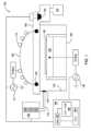
図1に以下の反応器の概略図を示す。プラズマ反応器/チャンバ100は、上部チャンバ本体105と下部チャンバ本体108とを備える。上部チャンバ本体105の上には誘電体ドーム120がある。チャンバ壁118は下部チャンバ本体を囲む。ドームの材質は
アルミナであり、チャンバ壁118の材質は陽極酸化アルミニウムである。誘電体ドーム120及びチャンバ壁118は一定の温度(ドームは80℃、チャンバ壁118は65℃)に維持される。 A schematic diagram of the reactor is shown in Figure 1. The plasma reactor/
高密度プラズマは、12.56MHzの高周波(RF)電源110を誘電体ドーム120上の誘導コイル115に印加することによって生成される。この誘電体ドーム120は上部チャンバ本体105の上に設置されている。静電チャック(図示せず)を備えたカソード125は、半導体ウェハ130を保持する。この半導体ウェハ130はまた、エッチングの間にヘリウム裏面冷却によって熱的に制御される。13.56MHzの別個のRFバイアス電源135がカソード125に印加され、ウェハ130へのイオン照射エネルギーを制御する。チャンバ100は、ドライメカニカルポンプ(図示せず)が補助する2000リットル/秒のターボ分子ポンプ140によって排気される。A high density plasma is generated by applying a 12.56 MHz radio frequency (RF) power supply 110 to an
処理ガスは、チャンバ壁の4つのガス分配リング145を通って、制御された流量で導入される。チャンバ圧力はスロットル弁150によって指定値に維持される。プリズム162、モノクロメータ164及びフォトダイオードアレイ(PDA)検出器166を備える光学分光器160を使用して、発光スペクトルを記録する。光信号はチャンバ内のセンサ170から収集され、マルチストランド光ファイバ175を介して送られる。センサ170はそのデータを分光器160に送信する。分光器160は、諸フリーラジカルをそれらの周波数及び波長に関連する化学物質に分類する。本明細書で使用される「化学物質」は、化学製品及び化学化合物を含むと広く定義される。分光器160は、フリーラジカルを化学物質(例えば、フッ素又は酸素)に、及び/又は化学化合物(例えば、硝酸フッ素又は硝酸ケイ素)に分類し得る。プロセッサリソースを節約するために、顧客/エンドユーザーは識別する化学物質を選択できる。Process gases are introduced at controlled flow rates through four gas distribution rings 145 in the chamber wall. The chamber pressure is maintained at a specified value by a
CPU182、メモリ184、及びCPU182のためのサポート回路186を備える制御システム180はプラズマ反応器100の様々な構成要素を制御する。メモリ184に格納されているソフトウェアルーチン又は一連のプログラム命令をCPU182が実行すると、反応器100は本明細書に開示される、材料の処理を実行する。様々な実施形態では、メモリ184はプログラム(図示せず)も含んで、本明細書に記載の実施形態を実施する。A
他の諸実施形態では、メモリ184はプログラム(図示せず)を含んで、フリーラジカルの波長及び周波数に基づいてチャンバ100内の化学物質を識別し、目標範囲と関連フリーラジカルの周波数及び波長との間の関係に基づいて警告を出し、チャンバ100内のフリーラジカルの周波数及び波長をその場で監視することによってグリーン-2-グリーンタイム(Green-2-Green Time)を増加させる。In other embodiments, the
プロセッサ182は、従来からのサポート回路186(電源、クロック回路、キャッシュメモリなど)の他に、メモリ184に格納されているソフトウェアルーチン(図示せず)の実行を支援する回路とも協働する。こうして、ソフトウェア処理として本明細書で論じる処理工程のいくつかを記憶装置(例えば、光学ドライブ、フロッピードライブ、ディスクドライブなど)からロードし、メモリ184内に実装してプロセッサ182で動作させることが企図される。したがって、本開示の様々な工程及び方法は、コンピュータ可読媒体に格納され得る。The
チャンバ100は定期的に予防保全(「PM」)整備を必要とし、この予防保全整備を本明細書では「PMサイクル」と呼ぶ。チャンバ100を製造から外して、そのツールの性能に基づいてPMサイクルを施してもよい。PMサイクルは、「マイナーPM」サイクル又は「メジャーPM」サイクルの形をとることができる。マイナーPMサイクルではほ
とんどの部品は変更されず、他方、メジャーPMでは多くの部品が変更される。PMを実行するには、チャンバ100を開放し、チャンバ100の外部の雰囲気にさらす必要がある。チャンバ100内でより多くの部品を交換することで、チャンバ100はより長時間開放され、チャンバ100内での水分(例えば、OH)への曝露が増すことになる。チャンバ100内に導入された部品もまた、チャンバ100内に水分(例えば、OH)を持ち込む。 The
チャンバ100を製造に戻すためには、チャンバ100は、シーズニングサイクルと認定サイクルとを受ける。本明細書に記載の諸実施形態によると、化学物質の波長及び周波数を監視して、シーズニングサイクルと認定サイクルを短縮し得る。例証のため、シーズニングサイクルと認定サイクルの間のOHレベルの変化を図3に示す。To return the
図2は、処理チャンバ100内の選択されたガスの周波数及び波長をその場で監視するための例示的な方法200を示す。例えば、シーズニングサイクルの間に、方法200はブロック202から始まり、ブロック204へ進む。ブロック204で、センサ170はチャンバ100内のガスのフリーラジカルの周波数及び波長をその場で監視する。2 illustrates an
ブロック206で、諸フリーラジカルは、それらの周波数及び波長に基づいて、少なくとも1つの化学製品と関連付けられる。例えば、塩素の指標となる波長及び周波数を有するフリーラジカルは塩素に関連付けられており、塩素用のチャネルに分類される。それらの周波数及び波長によって関連付けられ得る他のガスの例には、窒化炭素、酸素、フッ素、キセノン、炭素、アルゴン、ケイ素、窒化ケイ素、水素、水素化物がある。At
加えて、ある波長及び周波数の第1ケイ素は、第1ケイ素とは異なる波長及び周波数の第2ケイ素とは異なるように監視及び分類し得る。様々な実施形態では、(例えば、顧客が)選択を行って、1つの化学物質(製造サイクルの間のフッ素など)又は化学物質の任意の組み合わせ(シーズニングサイクルの間に通常、チャンバ内で見つかるすべての化学物質)を監視する。Additionally, a first silicon of one wavelength and frequency may be monitored and classified differently from a second silicon of a different wavelength and frequency than the first silicon. In various embodiments, a selection may be made (e.g., by the customer) to monitor one chemical (such as fluorine during a manufacturing cycle) or any combination of chemicals (such as all chemicals typically found in the chamber during a seasoning cycle).
ブロック208で、各チャネル内のフリーラジカル(すなわち関連フリーラジカル)をインデックス(図示せず)と比較する。インデックスは、少なくとも1つの化学製品中の各化学物質についての目標範囲を含む。例えば、1つの化学物質(例えばフッ素)が選択されている場合、フッ素の目標範囲は、チャンバ100内にあると識別されたフッ素に関連するフリーラジカルと比較するために選択される。ユーザは、どの関連フリーラジカルを監視するかを選択してもよい。ユーザはまた、関連フリーラジカルの強度の変化をグラフ化してもよい。例えば、シーズニングサイクルの間に、チャンバ100内で部品を交換し、次いでチャンバ100を閉じる。OHの指標となるフリーラジカルの波長及び周波数を監視し、OHのためのインデックスと比較してもよい。シーズニングサイクルの間に、シーズニングウェハを処理することにより、チャンバ100内のOHレベルが低下する。At block 208, the free radicals in each channel (i.e., associated free radicals) are compared to an index (not shown). The index includes a target range for each chemical in at least one chemical product. For example, if one chemical (e.g., fluorine) is selected, a target range for fluorine is selected to compare to the fluorine-associated free radicals identified to be in the
任意選択で、関連フリーラジカルをグラフ化してもよい。例えば、OH濃度から、チャンバ100内OH濃度が減少するグラフ表示が得られる。OHに関連するフリーラジカルをその場で監視しながら連続的にシーズニングウェハを処理することで、顧客はウェハを処理してOHを減少させ、ついには、OHは最小レベルになり得る(すなわち、OHレベルは安定しており、もはや急速には低下しない)。Optionally, the associated free radicals may be graphed. For example, the OH concentration provides a graphical representation of the decrease in OH concentration in the
新しい部品をチャンバ100内に配置したときにOHレベルが減少する曲線は、クリーニングされた部品を用いたときにOHレベルが減少する曲線とは、25枚のウェハをシーズニングしている期間で見ると、異なっている。図3は、曲線302と曲線304を有するグラフ300を示す。曲線302は、新しい部品がチャンバ100内にあるときの、各
シーズニングウェハ後のOH濃度の減少を示す。曲線304は、クリーニングされた部品がチャンバ100内にあるときの、各シーズニングウェハ後のOH濃度の減少を示す。チャンバ100内のOHの定常(変化率が小さい、又は変化がない)状態は、新品の部品と中古の部品とでは異なる。 The curve of the decrease in OH level when a new part is placed in the
OHが許容レベル又は定常レベルにあるとき、フッ素の指標となるフリーラジカルの波長及び周波数を監視して、チャンバ100内の部品によるチャンバ100内のフッ素レベルを測定してもよい。チャンバ100内の新しい部品は、クリーニングされた中古の部品よりも高いフッ素レベルをもたらすであろう。新しい部品を使用するとエッチングレートが変わって、ウェハが処理され得ることから、エッチングレートがより速くなる場合がある。クリーニングされた部品を使用すると、(新しい部品がもたらすレベルと比較して、)より低いフッ素レベルがもたらされ、エッチングレートが低下する場合がある。When OH is at an acceptable or steady state level, the wavelength and frequency of free radicals indicative of fluorine may be monitored to measure the fluorine level in the
フッ素レベルとOHレベルが許容レベルになると、シーズニングサイクルは終了になる。シーズニングサイクルが終了した後、認定サイクルのためにダミーウェハが処理される。OHレベルはその場で監視されており、OHの減少率が最小になる(又はOHが存在しなくなる)までウェハが処理されるので、認定時間は大幅に短縮される。例えば、25枚のウェハをシーズニングした後に認定サイクルを実行すれば、10枚のウェハをシーズニングした後に認定サイクルを実行する場合よりも、認定時間は短縮される。加えて、本明細書に開示される方法によれば、シーズニングサイクルを実行する必要なしにシーズニングとその後の認定試験を行い、認定サイクルを実行してから、ウェハが最初の認定に不合格の場合にシーズニングサイクルを再実行し、その後、2回目の認定サイクルを実行し得る。加えて、その場で関連フリーラジカルを監視することで、新しい部品やクリーニングされた部品(マイナーPMとメジャーPMのどちらでも)などの変化しやすいものが使用される場合の効率又はあるチャンバを他のチャンバと比較して使用した場合の変化が示される。Once the fluorine and OH levels are at acceptable levels, the seasoning cycle is terminated. After the seasoning cycle is completed, a dummy wafer is processed for a qualification cycle. The OH levels are monitored in situ, and wafers are processed until the rate of OH reduction is minimal (or no OH is present), greatly reducing the qualification time. For example, running a qualification cycle after seasoning 25 wafers will reduce the qualification time compared to running a qualification cycle after seasoning 10 wafers. In addition, the methods disclosed herein allow seasoning and subsequent qualification testing without the need to run a seasoning cycle, running a qualification cycle, then rerunning the seasoning cycle if the wafer fails the first qualification, and then running a second qualification cycle. Additionally, in situ monitoring of associated free radicals can indicate the efficiency of using variables such as new or cleaned parts (both minor and major PM) or changes when using one chamber compared to another.
図2に戻る。方法200はまた、任意選択のブロック210及び212を含む。任意選択のブロック210で、その場のチャンバ条件(「ICC」)処方策は、関連フリーラジカルが目標範囲内にない場合、比較に応じて変更される。例えば、関連フリーラジカルが目標範囲内にない場合、化学物質がチャンバに加えられる速度が変更され、エッチトレンチが変更される可能性がある。Returning to FIG. 2,
任意選択のブロック212で、関連フリーラジカルが目標範囲を下回った場合、チャンバ100を製造サイクルから外して、整備、シーズニング及び認定試験のために予防保全を施してもよい。関連フリーラジカルが目標範囲内にある場合、チャンバ100を再び製造サイクルに戻してもよい。In
また、本明細書に開示される実施形態を用いて、平均クリーニング間隔時間を増加させてもよい。加えて、フリーラジカルの波長及び周波数をその場で監視することにより、必要に応じて化学物質を加えることが可能になる。例えば、図4には、従来技術に対して、本明細書に開示された実施形態によりフッ素レベルをその場で監視し、増加させた、図解形式の比較400が示されている。図解形式の比較400は目標範囲402を含み、この目標範囲402は、フッ素レベルの許容動作範囲を示している。非許容レベル404は、フッ素レベルが非許容レベル404を下回った場合に、チャンバ100を製造から外して予防保全に置く必要があることを示す。波形406は、フッ素が、予防保全のレベルまで低下し、製造に戻るレベルまで復帰したことを示している。波形408は、本明細書に開示されている物質を利用しており、フッ素の指標となるフリーラジカルの波長及び周波数をその場で監視する工程と、フッ素が目標範囲の下限に近づいているときに、フッ素レベルを増加させる工程とを含む。フッ素を加えた結果が、波形部分410に示されている。
やがて時間が経過すると、フッ素レベルが低下し始めることが、波形部分412に示されている。フッ素レベルが再び目標範囲の下限に近づくと、フッ素を再びチャンバ100に加え得る。その場で監視し、チャンバ内にフッ素を繰り返し加えることによって、平均クリーニング間隔時間を長くし得る。例えば、平均クリーニング間隔時間を、マイナーPMもメジャーPMも必要なく、600RF時間をはるかに超えて増加させ得る。 The average time between cleanings may also be increased using embodiments disclosed herein. Additionally, in situ monitoring of free radical wavelengths and frequencies allows for chemicals to be added as needed. For example, FIG. 4 shows a graphical comparison 400 of in situ monitoring and increasing fluorine levels using embodiments disclosed herein versus the prior art. The graphical comparison 400 includes a target range 402, which indicates an acceptable operating range for fluorine levels. An unacceptable level 404 indicates that the
Over time, the fluorine level begins to drop, as shown by waveform portion 412. When the fluorine level again approaches the lower end of the target range, fluorine can again be added to the
本明細書では、「有する」、「含有する」、「含む」、「備える」などの用語は、記載の要素又は構成が存在することを示すが、さらなる要素又は構成が加わることを排除するものではないオープンエンド型の用語である。冠詞「a」、「an」、及び「the」は、文脈において別途明示されない限り、複数及び単数を含むものとする。As used herein, terms such as "have," "contain," "include," "comprise," and the like are open-ended terms that indicate the presence of a stated element or configuration, but do not exclude the addition of additional elements or configurations. The articles "a," "an," and "the" are intended to include the plural and the singular, unless the context clearly indicates otherwise.
上記は本開示の実施形態を対象としているが、本開示の他のさらなる実施形態を、その基本的な範囲から逸脱することなく創作することができ、その範囲は以下の特許請求の範囲に基づいて定められる。The foregoing is directed to embodiments of the present disclosure, however, other and further embodiments of the present disclosure may be created without departing from the basic scope thereof, which is defined by the following claims.
Claims (1)
Translated fromJapaneseフリーラジカルの周波数及び波長を少なくとも1つの選択された化学製品と関連付ける工程と、
関連フリーラジカルをインデックスと比較する工程であって、インデックスは、少なくとも1つの選択された化学製品中の各化学物質についての目標範囲を含んでいる工程とを含む方法。 monitoring in situ the frequency and wavelength of the free radicals in the chamber for each wafer in the chamber;
Associating the frequencies and wavelengths of the free radicals with at least one selected chemical product;
and comparing the associated free radicals to an index, the index including a target range for each chemical in the at least one selected chemical product.
Applications Claiming Priority (5)
| Application Number | Priority Date | Filing Date | Title |
|---|---|---|---|
| IN201841045267 | 2018-11-30 | ||
| IN201841045267 | 2018-11-30 | ||
| US16/355,138 | 2019-03-15 | ||
| US16/355,138US10854433B2 (en) | 2018-11-30 | 2019-03-15 | In-situ real-time plasma chamber condition monitoring |
| JP2019215016AJP7646289B2 (en) | 2018-11-30 | 2019-11-28 | In-situ, real-time plasma chamber condition monitoring |
Related Parent Applications (1)
| Application Number | Title | Priority Date | Filing Date |
|---|---|---|---|
| JP2019215016ADivisionJP7646289B2 (en) | 2018-11-30 | 2019-11-28 | In-situ, real-time plasma chamber condition monitoring |
Publications (1)
| Publication Number | Publication Date |
|---|---|
| JP2024178337Atrue JP2024178337A (en) | 2024-12-24 |
Family
ID=70849356
Family Applications (2)
| Application Number | Title | Priority Date | Filing Date |
|---|---|---|---|
| JP2019215016AActiveJP7646289B2 (en) | 2018-11-30 | 2019-11-28 | In-situ, real-time plasma chamber condition monitoring |
| JP2024164697APendingJP2024178337A (en) | 2018-11-30 | 2024-09-24 | In-situ, real-time plasma chamber condition monitoring |
Family Applications Before (1)
| Application Number | Title | Priority Date | Filing Date |
|---|---|---|---|
| JP2019215016AActiveJP7646289B2 (en) | 2018-11-30 | 2019-11-28 | In-situ, real-time plasma chamber condition monitoring |
Country Status (4)
| Country | Link |
|---|---|
| US (1) | US10854433B2 (en) |
| JP (2) | JP7646289B2 (en) |
| KR (1) | KR102810904B1 (en) |
| CN (1) | CN111261544A (en) |
Families Citing this family (4)
| Publication number | Priority date | Publication date | Assignee | Title |
|---|---|---|---|---|
| US12243721B2 (en)* | 2020-08-14 | 2025-03-04 | Np Holdings Co., Ltd. | Plasma generating device and process executing apparatus including the same |
| US12072267B2 (en)* | 2020-08-31 | 2024-08-27 | Applied Materials, Inc. | Method and hardware for post maintenance vacuum recovery system |
| WO2024107561A1 (en)* | 2022-11-16 | 2024-05-23 | Mks Instruments, Inc. | Radical sensing for process tool diagnostics |
| US20250140541A1 (en)* | 2023-10-25 | 2025-05-01 | Applied Materials, Inc. | Real-time plasma measurement and control |
Citations (9)
| Publication number | Priority date | Publication date | Assignee | Title |
|---|---|---|---|---|
| JP2002110642A (en)* | 2000-09-27 | 2002-04-12 | Sharp Corp | Plasma processing method |
| US20040263827A1 (en)* | 2003-06-26 | 2004-12-30 | Applied Materials, Inc. | Novel methodology for in-situ and real-time chamber condition monitoring and process recovery during plasma processing |
| JP2007073751A (en)* | 2005-09-07 | 2007-03-22 | Hitachi High-Technologies Corp | Plasma processing apparatus and processing method |
| JP2007324341A (en)* | 2006-05-31 | 2007-12-13 | Hitachi High-Technologies Corp | Plasma processing method and plasma processing apparatus |
| JP2008244107A (en)* | 2007-03-27 | 2008-10-09 | Hitachi High-Technologies Corp | Etching rate measuring apparatus and measuring method |
| JP2010147052A (en)* | 2008-12-16 | 2010-07-01 | Tokyo Electron Ltd | Plasma processing method, plasma processing apparatus, and moisture content detecting method of plasma processing apparatus |
| JP2013105923A (en)* | 2011-11-15 | 2013-05-30 | Hitachi High-Technologies Corp | Plasma processing apparatus and plasma processing method |
| JP2017017067A (en)* | 2015-06-26 | 2017-01-19 | 株式会社日立ハイテクノロジーズ | Plasma processing device and data analysis device for the same |
| JP2017045849A (en)* | 2015-08-26 | 2017-03-02 | 東京エレクトロン株式会社 | Seasoning method and etching method |
Family Cites Families (11)
| Publication number | Priority date | Publication date | Assignee | Title |
|---|---|---|---|---|
| CA2065581C (en)* | 1991-04-22 | 2002-03-12 | Andal Corp. | Plasma enhancement apparatus and method for physical vapor deposition |
| US5877032A (en)* | 1995-10-12 | 1999-03-02 | Lucent Technologies Inc. | Process for device fabrication in which the plasma etch is controlled by monitoring optical emission |
| JPH10189542A (en)* | 1996-12-26 | 1998-07-21 | Sumitomo Metal Ind Ltd | Plasma etching method |
| US6534007B1 (en)* | 1997-08-01 | 2003-03-18 | Applied Komatsu Technology, Inc. | Method and apparatus for detecting the endpoint of a chamber cleaning |
| US20040235299A1 (en)* | 2003-05-22 | 2004-11-25 | Axcelis Technologies, Inc. | Plasma ashing apparatus and endpoint detection process |
| US7261745B2 (en)* | 2003-09-30 | 2007-08-28 | Agere Systems Inc. | Real-time gate etch critical dimension control by oxygen monitoring |
| JP2010161350A (en)* | 2008-12-09 | 2010-07-22 | Hitachi Kokusai Electric Inc | Substrate treating method |
| EP2711342A4 (en)* | 2011-05-17 | 2014-04-09 | Panasonic Corp | APPARATUS AND METHOD FOR GENERATING PLASMA |
| US20140262028A1 (en)* | 2013-03-13 | 2014-09-18 | Intermolecular, Inc. | Non-Contact Wet-Process Cell Confining Liquid to a Region of a Solid Surface by Differential Pressure |
| US20150126036A1 (en)* | 2013-11-05 | 2015-05-07 | Tokyo Electron Limited | Controlling etch rate drift and particles during plasma processing |
| US11037798B2 (en)* | 2016-11-09 | 2021-06-15 | Tokyo Electron Limited | Self-limiting cyclic etch method for carbon-based films |
- 2019
- 2019-03-15USUS16/355,138patent/US10854433B2/enactiveActive
- 2019-05-29CNCN201910457530.1Apatent/CN111261544A/enactivePending
- 2019-06-18KRKR1020190072378Apatent/KR102810904B1/enactiveActive
- 2019-11-28JPJP2019215016Apatent/JP7646289B2/enactiveActive
- 2024
- 2024-09-24JPJP2024164697Apatent/JP2024178337A/enactivePending
Patent Citations (9)
| Publication number | Priority date | Publication date | Assignee | Title |
|---|---|---|---|---|
| JP2002110642A (en)* | 2000-09-27 | 2002-04-12 | Sharp Corp | Plasma processing method |
| US20040263827A1 (en)* | 2003-06-26 | 2004-12-30 | Applied Materials, Inc. | Novel methodology for in-situ and real-time chamber condition monitoring and process recovery during plasma processing |
| JP2007073751A (en)* | 2005-09-07 | 2007-03-22 | Hitachi High-Technologies Corp | Plasma processing apparatus and processing method |
| JP2007324341A (en)* | 2006-05-31 | 2007-12-13 | Hitachi High-Technologies Corp | Plasma processing method and plasma processing apparatus |
| JP2008244107A (en)* | 2007-03-27 | 2008-10-09 | Hitachi High-Technologies Corp | Etching rate measuring apparatus and measuring method |
| JP2010147052A (en)* | 2008-12-16 | 2010-07-01 | Tokyo Electron Ltd | Plasma processing method, plasma processing apparatus, and moisture content detecting method of plasma processing apparatus |
| JP2013105923A (en)* | 2011-11-15 | 2013-05-30 | Hitachi High-Technologies Corp | Plasma processing apparatus and plasma processing method |
| JP2017017067A (en)* | 2015-06-26 | 2017-01-19 | 株式会社日立ハイテクノロジーズ | Plasma processing device and data analysis device for the same |
| JP2017045849A (en)* | 2015-08-26 | 2017-03-02 | 東京エレクトロン株式会社 | Seasoning method and etching method |
Also Published As
| Publication number | Publication date |
|---|---|
| CN111261544A (en) | 2020-06-09 |
| KR102810904B1 (en) | 2025-05-20 |
| JP7646289B2 (en) | 2025-03-17 |
| KR20200066541A (en) | 2020-06-10 |
| US10854433B2 (en) | 2020-12-01 |
| US20200176233A1 (en) | 2020-06-04 |
| JP2020088397A (en) | 2020-06-04 |
Similar Documents
| Publication | Publication Date | Title |
|---|---|---|
| JP7646289B2 (en) | In-situ, real-time plasma chamber condition monitoring | |
| TWI656573B (en) | Dry etching treatment feature control using optical emission spectroscopy of waferless dry cleaning | |
| US7067432B2 (en) | Methodology for in-situ and real-time chamber condition monitoring and process recovery during plasma processing | |
| US6499492B1 (en) | Plasma process apparatus with in situ monitoring, monitoring method, and in situ residue cleaning | |
| JP4464276B2 (en) | Plasma processing method and plasma processing apparatus | |
| JP4914119B2 (en) | Plasma processing method and plasma processing apparatus | |
| US11257698B2 (en) | Selective etch rate monitor | |
| US7959970B2 (en) | System and method of removing chamber residues from a plasma processing system in a dry cleaning process | |
| CN101145499A (en) | On-line predication method for maintaining etching apparatus | |
| JP2003264179A (en) | Method for detecting end of seasoning and plasma treatment method | |
| TW201831052A (en) | Consumption determination method and plasma processing device | |
| JP2004039805A (en) | Method of predicting process and treatment apparatus | |
| US6660528B1 (en) | Method for monitoring contaminating particles in a chamber | |
| US20070074741A1 (en) | Method for dry cleaning nickel deposits from a processing system | |
| US7354778B2 (en) | Method for determining the end point for a cleaning etching process | |
| Hussein et al. | Particle control in dielectric etch chamber | |
| WO2025038660A1 (en) | Method and system for monitoring radical species flux of plasma | |
| JP2005019763A (en) | Dry etching device | |
| IE20020141A1 (en) | Plasma chamber conditioning |
Legal Events
| Date | Code | Title | Description |
|---|---|---|---|
| A521 | Request for written amendment filed | Free format text:JAPANESE INTERMEDIATE CODE: A523 Effective date:20241016 | |
| A621 | Written request for application examination | Free format text:JAPANESE INTERMEDIATE CODE: A621 Effective date:20241016 | |
| A131 | Notification of reasons for refusal | Free format text:JAPANESE INTERMEDIATE CODE: A131 Effective date:20250729 |