JP2024175152A - Compensation system, compensation device, compensation method, and program - Google Patents
Compensation system, compensation device, compensation method, and programDownload PDFInfo
- Publication number
- JP2024175152A JP2024175152AJP2021178390AJP2021178390AJP2024175152AJP 2024175152 AJP2024175152 AJP 2024175152AJP 2021178390 AJP2021178390 AJP 2021178390AJP 2021178390 AJP2021178390 AJP 2021178390AJP 2024175152 AJP2024175152 AJP 2024175152A
- Authority
- JP
- Japan
- Prior art keywords
- compensation
- master device
- operator
- unit
- force
- Prior art date
- Legal status (The legal status is an assumption and is not a legal conclusion. Google has not performed a legal analysis and makes no representation as to the accuracy of the status listed.)
- Pending
Links
Images


Classifications
- A—HUMAN NECESSITIES
- A61—MEDICAL OR VETERINARY SCIENCE; HYGIENE
- A61B—DIAGNOSIS; SURGERY; IDENTIFICATION
- A61B34/00—Computer-aided surgery; Manipulators or robots specially adapted for use in surgery
- A61B34/30—Surgical robots
- A61B34/35—Surgical robots for telesurgery
- B—PERFORMING OPERATIONS; TRANSPORTING
- B25—HAND TOOLS; PORTABLE POWER-DRIVEN TOOLS; MANIPULATORS
- B25J—MANIPULATORS; CHAMBERS PROVIDED WITH MANIPULATION DEVICES
- B25J3/00—Manipulators of leader-follower type, i.e. both controlling unit and controlled unit perform corresponding spatial movements
Landscapes
- Engineering & Computer Science (AREA)
- Health & Medical Sciences (AREA)
- Surgery (AREA)
- Robotics (AREA)
- Life Sciences & Earth Sciences (AREA)
- Heart & Thoracic Surgery (AREA)
- Nuclear Medicine, Radiotherapy & Molecular Imaging (AREA)
- Biomedical Technology (AREA)
- Mechanical Engineering (AREA)
- Medical Informatics (AREA)
- Molecular Biology (AREA)
- Animal Behavior & Ethology (AREA)
- General Health & Medical Sciences (AREA)
- Public Health (AREA)
- Veterinary Medicine (AREA)
- Manipulator (AREA)
Abstract
Description
Translated fromJapanese本発明は、補償システム、補償装置、補償方法及びプログラムに関する。The present invention relates to a compensation system, a compensation device, a compensation method, and a program.
従来、操作者の操作が入力されるマスタ装置と、マスタ装置に入力される操作に応じて動作するスレーブ装置とにおいて、スレーブ装置側の動作に応じた反力を、マスタ装置側に力触覚として伝達するというバイラテラル制御の技術が知られている。また、このようなバイラテラル制御を行う際に、摩擦力を補償する構成が知られている(例えば、特許文献1参照)。Conventionally, a bilateral control technique is known in which a master device receives input of an operator's operation, and a slave device operates in response to the operation input to the master device, and a reaction force corresponding to the operation of the slave device is transmitted to the master device as a haptic sensation. In addition, a configuration is known that compensates for frictional forces when performing such bilateral control (see, for example, Patent Document 1).
上述したような摩擦力の補償を行うことで、操作者による操作を支援することができる。しかしながら、摩擦力の補償を常時行った場合に、不具合が生じる場合がある。例えば、摩擦力の補償を常時行ったことにより、操作者が意図せず生じた振動が増幅してしまうような場合がある。By performing the above-mentioned friction force compensation, it is possible to assist the operator in performing the operation. However, problems may arise when friction force compensation is performed constantly. For example, constant compensation for friction force may result in amplified vibrations that are generated unintentionally by the operator.
本発明は、このような状況に鑑みてなされたものである。そして、本発明の課題は、より適切な状況で、摩擦補償を行うことである。The present invention was made in light of these circumstances. The objective of the present invention is to perform friction compensation in more appropriate situations.
上記課題を解決するため、本発明の一態様に係る補償システムは、
操作者の操作が入力されるマスタ装置と、前記マスタ装置に入力された操作に応じて動作するスレーブ装置と、を含む補償システムであって、
前記マスタ装置及び前記スレーブ装置における力触覚の伝達を制御する制御手段と、
前記操作者による前記マスタ装置に対する操作の状態を判定する判定手段と、
前記判定手段による判定結果に基づいて摩擦補償を行うか否かを決定し、摩擦補償を行うと決定した場合には、前記制御手段による力触覚の伝達に影響する摩擦に対して摩擦補償を行う補償手段と、
を備えることを特徴とする。 In order to solve the above problem, a compensation system according to one aspect of the present invention comprises:
A compensation system including a master device to which an operation by an operator is input, and a slave device that operates in response to the operation input to the master device,
a control means for controlling the transmission of haptic sensations between the master device and the slave device;
a determination means for determining a state of an operation performed by the operator on the master device;
a compensation means for determining whether or not to perform friction compensation based on a result of the determination by the determination means, and when it is determined that friction compensation should be performed, performing friction compensation for friction that affects the transmission of the haptic sensation by the control means;
The present invention is characterized by comprising:
本発明によれば、より適切な状況で、摩擦補償を行うことが可能となる。The present invention makes it possible to perform friction compensation in more appropriate situations.
以下、本発明の実施形態について、図面を参照して説明する。The following describes an embodiment of the present invention with reference to the drawings.
[構成]
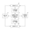
図1は、本発明の一実施形態に係る補償システム1の全体構成を示す模式図である。
図1に示すように、本実施形態に係る補償システム1は、機械的に分離したマスタ装置10とスレーブ装置20とを含むマスタ・スレーブシステムとして構成される。一例として、本実施形態における補償システム1は、マスタ装置10が操作者により操作されるマニピュレータを構成し、スレーブ装置20が被検体に挿入されるエンドエフェクタを備えたカテーテルシステムを構成するものとする。[composition]
FIG. 1 is a schematic diagram showing the overall configuration of a
1, a
図1において、補償システム1は、マスタ装置10と、スレーブ装置20と、制御装置30と、を含んで構成され、マスタ装置10及びスレーブ装置20と、制御装置30とは、ネットワーク40を介して有線または無線通信可能に構成されている。なお、補償システム1は、ディスプレイLと、複数のカメラCとを適宜備えることが可能である。カメラCとして、マスタ装置10を操作する操作者の外観(例えば、マスタ装置10に対する操作の状態)を撮影するビデオカメラ、スレーブ装置20が挿入される被検体の外観(例えば、スレーブ装置20の挿入状態)を撮影するビデオカメラ、あるいは、X線により被検体の内部(例えば、被検体の血管や臓器)を撮影するX線カメラ等の種々の撮影装置を用いることができる。また、複数のカメラCによって撮影された各種画像や、制御装置30から出力される各種情報を表示する複数のディスプレイLを備えることもできる。In FIG. 1, the
マスタ装置10は、機械的に構成された従来のカテーテルに対する操作と同様の操作を受け付け、入力された操作により移動する可動部(マニピュレータの可動部材等)の位置を検出する。マスタ装置10は、検出した可動部の位置を表す情報を制御装置30に送信する。また、マスタ装置10は、入力される操作に対し、制御装置30の指示に従って、アクチュエータにより反力を出力する。The
具体的には、マスタ装置10は、カテーテルを進退させる操作(例えば、血管内に挿入していく操作または病変付近で力触覚を検知するために微動させる操作等)、カテーテルを軸回りに回転させる操作(例えば、エンドエフェクタの向きを変化させる操作等)、及び、エンドエフェクタを動作させる操作(例えば、エンドエフェクタがバルーンである場合、これを拡張、収縮させる操作、またエンドエフェクタが鉗子等の場合、これを開閉する操作等)を受け付け、これらの操作に対する反力を付与すると共に、それぞれの操作により移動される可動部の位置を表す情報を制御装置30に送信する。Specifically, the
スレーブ装置20は、制御装置30の指示に従って、アクチュエータを駆動することにより、マスタ装置10に入力された操作に対応する動作を行い、動作により移動する可動部(アクチュエータの可動子あるいはアクチュエータによって移動されるカテーテル等)の位置を検出する。スレーブ装置20が動作することにより、スレーブ装置20に対して環境から各種外力が入力する。この結果、スレーブ装置20における可動部の位置は、アクチュエータの出力に対して各種外力が作用した結果を示すものとなる。そして、スレーブ装置20は、検出した可動部の位置を表す情報を制御装置30に送信する。ここで、スレーブ装置20に対して環境から入力する各種外力には、例えば、被検体に挿入されたカテーテルが血管から受けるスラスト方向の抵抗力と、カテーテル先端に配置されたガイドワイヤやエンドエフェクタ等が病変や臓器や血管に接触した場合の当接力が含まれる。The
ここで、スレーブ装置20におけるスラスト方向の抵抗力が大きい場合、カテーテルに入力する他の外力(病変や器官に接触した場合の当接力等)を知覚し難くなる可能性がある。本実施形態においては、後述するように、所定の摩擦補償量を、マスタ装置10における操作者の操作をアシストするための力として出力する。これにより、マスタ装置10を操作する操作者の負荷を低減しつつ、スレーブ装置20の状態変化を知覚させ易くすることができる。すなわち、摩擦補償により、マスタ装置10における操作者の操作をアシストすることができる。Here, if the resistance force in the thrust direction in the
制御装置30は、例えば、PC(Personal Computer)あるいはサーバコンピュータ等の情報処理装置によって構成され、マスタ装置10、スレーブ装置20、ディスプレイL及びカメラCを制御する。例えば、制御装置30は、マスタ装置10及びスレーブ装置20の可動部の位置(ロータリーエンコーダによって検出されるアクチュエータの回転角度あるいはリニアエンコーダによって検出される可動部の進退位置等)を取得し、マスタ装置10及びスレーブ装置20の間で力触覚を伝達するための制御を実行する。The
本実施形態における制御装置30は、マスタ装置10とスレーブ装置20とをマスタ・スレーブシステムとして動作させる際に、可動部の位置を表す情報(アクチュエータの可動子の位置あるいはアクチュエータによって移動される部材の位置等を表す情報)を基に算出した実空間のパラメータ(入力ベクトル)を、位置と力とを独立して取り扱うことが可能な仮想空間に座標変換(変換行列によって変換)する。すなわち、入力ベクトルが、位置と力とが互いに関連する斜交座標系の実空間から、位置と力とが互いに独立した直交座標系の仮想空間に座標変換される。座標変換によって算出されたパラメータは、仮想空間において、入力ベクトルに対応する位置及び力の状態値を表すものとなる。そして、制御装置30は、座標変換後の仮想空間において、入力ベクトルから算出された位置及び力の状態値を、位置及び力の制御(ここでは力触覚の伝達)を行うための位置及び力それぞれの目標値に追従させる演算を行い、演算結果を実空間に戻すための逆変換(変換行列の逆行列による変換)を行う。さらに、制御装置30は、逆変換によって取得された実空間のパラメータ(電流指令値等)に基づいて、各アクチュエータを駆動することにより、マスタ装置10とスレーブ装置20との間で力触覚を伝達するマスタ・スレーブシステムを実現する。In this embodiment, when the
なお、位置と速度(または加速度)あるいは角度と角速度(または角加速度)は、微積分演算により置換可能なパラメータであるため、位置あるいは角度に関する処理を行う場合、適宜、速度あるいは角速度等に置換することが可能である。Note that position and velocity (or acceleration) or angle and angular velocity (or angular acceleration) are parameters that can be replaced by differential and integral calculations, so when performing processing related to position or angle, they can be replaced with velocity or angular velocity, etc., as appropriate.
このような構成において、本実施形態における補償システム1は、上述のようにマスタ装置10とスレーブ装置20との間で力触覚を伝達するマスタ・スレーブシステムを実現すると共に、補償制御処理を行う。ここで、補償制御処理は、力触覚の伝達時に摩擦補償を行うに際し、適切な状況で摩擦補償を行うための制御を行う一連の処理である。
具体的に、補償制御処理において、補償システム1は、マスタ装置10及びスレーブ装置20における力触覚の伝達を制御する。また、補償システム1は、状態判定部352は、操作者によるマスタ装置10に対する操作の状態を判定する。さらに、補償システム1は、状態判定部352による判定結果に基づいて摩擦補償を行うか否かを決定し、摩擦補償を行うと決定した場合には、力触覚伝達部354による力触覚の伝達に影響する摩擦に対して摩擦補償を行う。 In this configuration, the
Specifically, in the compensation control process, the
このように、補償システム1は、力触覚の伝達時に摩擦補償を行うに際し、操作者によるマスタ装置10に対する操作の状態に基づいて摩擦補償を行うか否かを決定する。すなわち、摩擦力の補償を常時行うのではなく、操作の状態に対応した適切なタイミングで摩擦補償を行う。これにより、例えば、摩擦力の補償を常時行ったことにより、操作者が意図せず生じた振動が増幅してしまうような不具合の発生を防止することができる。
従って、補償システム1によれば、より適切な状況で、摩擦補償を行う、という課題を解決することができる。 In this way, when performing friction compensation during transmission of haptic sensation, the
Therefore, the
図2は、制御装置30で実行される力触覚伝達制御の基本的原理を示す模式図である。
図2に示す基本的原理は、可動部の位置を表す情報(可動部の現在位置)を入力として、速度あるいは力の少なくとも一方の領域における演算を行うことにより、アクチュエータの動作を決定するものである。
すなわち、本発明の基本的原理は、制御対象システムSと、機能別力・速度割当変換ブロックFTと、理想力源ブロックFCあるいは理想速度源ブロックPCの少なくとも1つと、逆変換ブロックIFTとを含む制御則として表される。 FIG. 2 is a schematic diagram showing the basic principle of the haptic transmission control executed by the
The basic principle shown in FIG. 2 is to determine the operation of the actuator by inputting information representing the position of the movable part (the current position of the movable part) and performing calculations in at least one of the areas of velocity and force.
That is, the basic principle of the present invention is expressed as a control law including a controlled system S, a functional force/speed allocation conversion block FT, at least one of an ideal force source block FC or an ideal speed source block PC, and an inverse conversion block IFT.
制御対象システムSは、アクチュエータを備えるマスタ装置10あるいはスレーブ装置20であり、加速度等に基づいてアクチュエータの制御を行う。ここで、上述したように、加速度、速度及び位置は、微積分によって相互に換算可能な物理量であるため、加速度、速度及び位置のいずれを用いて制御することとしてもよい。ここでは、主として、位置から算出される速度を用いて制御則を表現するものとする。The controlled system S is a
機能別力・速度割当変換ブロックFTは、制御対象システムSの機能に応じて設定される速度及び力の領域への制御エネルギーの変換を定義するブロックである。具体的には、機能別力・速度割当変換ブロックFTでは、制御対象システムSの機能の基準となる値(基準値)と、可動部の現在位置とを入力とする座標変換が定義されている。この座標変換は、一般に、基準値及び現在速度を要素とする入力ベクトルを速度の制御目標値を算出するための速度からなる出力ベクトルに変換すると共に、基準値及び現在の力を要素とする入力ベクトルを力の制御目標値を算出するための力からなる出力ベクトルに変換するものである。具体的には、機能別力・速度割当変換ブロックFTにおける座標変換は、次式(1)及び(2)のように一般化して表される。The functional force-speed allocation conversion block FT is a block that defines the conversion of control energy into a range of speeds and forces that are set according to the functions of the controlled system S. Specifically, the functional force-speed allocation conversion block FT defines a coordinate conversion that uses as inputs a value (reference value) that is the reference for the function of the controlled system S and the current position of the moving part. This coordinate conversion generally converts an input vector whose elements are the reference value and the current speed into an output vector consisting of a speed for calculating a target value for speed control, and also converts an input vector whose elements are the reference value and the current force into an output vector consisting of a force for calculating a target value for force control. Specifically, the coordinate conversion in the functional force-speed allocation conversion block FT is generalized and expressed as the following equations (1) and (2).

ただし、式(1)において、x’1~x’n(nは1以上の整数)は速度の状態値を導出するための速度ベクトルであり、x’a~x’m(mは1以上の整数)は、基準値及びアクチュエータの作用に基づく速度(アクチュエータの可動子の速度またはアクチュエータが移動させる部材の速度)を要素とするベクトル、h1a~hnmは機能を表す変換行列の要素である。また、式(2)において、f’’1~f’’n(nは1以上の整数)は力の状態値を導出するための力ベクトルであり、f’’a~f’’m(mは1以上の整数)は、基準値及びアクチュエータの作用に基づく力(アクチュエータの可動子の力またはアクチュエータが移動させる部材の力)を要素とするベクトルである。 However, in equation (1),x'1 tox'n (n is an integer of 1 or greater) are velocity vectors for deriving a state value of velocity,x'a tox'm (m is an integer of 1 or greater) are vectors whose elements are reference values and velocities based on the action of the actuator (the velocity of the actuator's mover or the velocity of a member moved by the actuator), andh1a tohnm are elements of a transformation matrix representing a function. Also, in equation (2),f''1 tof''n (n is an integer of 1 or greater) are force vectors for deriving a state value of force, andf''a to f''m (m is an integer of 1 or greater) are vectors whose elements are reference values and forces based on the action of the actuator (the force of the actuator's mover or the force of a member moved by the actuator).
機能別力・速度割当変換ブロックFTにおける座標変換を、実現する機能に応じて設定することにより、各種動作を実現したり、スケーリングを行ったりすることができる。
すなわち、本発明の基本的原理では、機能別力・速度割当変換ブロックFTにおいて、アクチュエータ単体の変数(実空間上の変数)を、実現する機能を表現するシステム全体の変数群(仮想空間上の変数)に“変換”し、速度の制御エネルギーと力の制御エネルギーとに制御エネルギーを割り当てる。換言すると、本発明の基本的原理では、速度と力とが互いに関連する座標空間から、速度と力とが互いに独立した座標空間に変換した上で、速度及び力の制御に関する演算を行う。そのため、アクチュエータ単体の変数(実空間上の変数)のまま制御を行う場合と比較して、速度の制御エネルギーと力の制御エネルギーとを独立に与えることが可能となっている。 By setting the coordinate transformation in the functional force/speed allocation transformation block FT according to the function to be realized, it is possible to realize various operations and perform scaling.
That is, in the basic principle of the present invention, the function-specific force/speed allocation conversion block FT "converts" the variables of the actuator alone (variables in real space) into a group of variables of the entire system (variables in virtual space) that express the functions to be realized, and allocates the control energy to the speed control energy and the force control energy. In other words, in the basic principle of the present invention, calculations related to the control of the speed and force are performed after converting from a coordinate space in which the speed and force are related to each other to a coordinate space in which the speed and force are independent of each other. Therefore, compared to the case where control is performed using the variables of the actuator alone (variables in real space), it is possible to provide the speed control energy and the force control energy independently.
理想力源ブロックFCは、機能別力・速度割当変換ブロックFTによって定義された座標変換に従って、力の領域における演算を行うブロックである。理想力源ブロックFCにおいては、機能別力・速度割当変換ブロックFTによって定義された座標変換に基づく演算を行う際の力に関する目標値が設定されている。この目標値は、実現される機能に応じて固定値または可変値として設定される。例えば、基準値が示す機能と同様の機能を実現する場合には、目標値としてゼロを設定したり、スケーリングを行う場合には、実現する機能を示す情報を拡大・縮小した値を設定したりできる。The ideal force source block FC is a block that performs calculations in the domain of force according to the coordinate transformation defined by the functional force-speed allocation transformation block FT. In the ideal force source block FC, a target value for force is set when performing calculations based on the coordinate transformation defined by the functional force-speed allocation transformation block FT. This target value is set as a fixed value or a variable value depending on the function to be realized. For example, when realizing a function similar to the function indicated by the reference value, zero can be set as the target value, and when scaling is performed, a value obtained by enlarging or reducing the information indicating the function to be realized can be set.
理想速度源ブロックPCは、機能別力・速度割当変換ブロックFTによって定義された座標変換に従って、速度の領域における演算を行うブロックである。理想速度源ブロックPCにおいては、機能別力・速度割当変換ブロックFTによって定義された座標変換に基づく演算を行う際の速度に関する目標値が設定されている。この目標値は、実現される機能に応じて固定値または可変値として設定される。例えば、基準値が示す機能と同様の機能を実現する場合には、目標値としてゼロを設定したり、スケーリングを行う場合には、実現する機能を示す情報を拡大・縮小した値を設定したりできる。The ideal speed source block PC is a block that performs calculations in the domain of speed according to the coordinate transformation defined by the functional force-speed allocation transformation block FT. In the ideal speed source block PC, a target value for speed is set when performing calculations based on the coordinate transformation defined by the functional force-speed allocation transformation block FT. This target value is set as a fixed value or a variable value depending on the function to be realized. For example, when realizing a function similar to the function indicated by the reference value, zero can be set as the target value, and when scaling is performed, a value obtained by enlarging or reducing the information indicating the function to be realized can be set.
逆変換ブロックIFTは、速度及び力の領域の値を制御対象システムSへの入力の領域の値(例えば電圧値または電流値等)に変換するブロックである。
このような基本的原理により、制御対象システムSのアクチュエータにおける位置の情報が機能別力・速度割当変換ブロックFTに入力されると、位置の情報に基づいて得られる速度及び力の情報を用いて、機能別力・速度割当変換ブロックFTにおいて、機能に応じた位置及び力の領域それぞれの制御則が適用される。そして、理想力源ブロックFCにおいて、機能に応じた力の演算が行われ、理想速度源ブロックPCにおいて、機能に応じた速度の演算が行われ、力及び速度それぞれに制御エネルギーが分配される。 The inverse transformation block IFT is a block that transforms values in the domains of velocity and force into values in the domain of the input to the controlled system S (for example, voltage values or current values, etc.).
According to this basic principle, when position information of the actuator of the controlled system S is input to the function-specific force/speed allocation conversion block FT, the function-specific force/speed allocation conversion block FT applies a control rule for each of the position and force regions according to the function using the speed and force information obtained based on the position information. Then, the ideal force source block FC calculates the force according to the function, and the ideal speed source block PC calculates the speed according to the function, and the control energy is distributed to each of the force and speed.
理想力源ブロックFC及び理想速度源ブロックPCにおける演算結果は、制御対象システムSの制御目標を示す情報となり、これらの演算結果が逆変換ブロックIFTにおいてアクチュエータの入力値とされて、制御対象システムSに入力される。
その結果、制御対象システムSのアクチュエータは、機能別力・速度割当変換ブロックFTによって定義された機能に従う動作を実行し、目的とする装置の動作が実現される。 The calculation results in the ideal force source block FC and the ideal velocity source block PC become information indicating the control target of the controlled system S, and these calculation results are used as input values for the actuators in the inverse transformation block IFT and input to the controlled system S.
As a result, the actuators of the controlled system S execute operations in accordance with the functions defined by the functional force/speed allocation conversion block FT, and the intended operation of the device is realized.
また、スケーリング(力あるいは位置の増幅や縮小)を伴う力触覚伝達機能が実現される場合、図2における機能別力・速度割当変換ブロックFTにおける座標変換は、次式(3)及び(4)として表される。When a force-tactile transmission function involving scaling (amplification or reduction of force or position) is realized, the coordinate transformation in the functional force-velocity allocation transformation block FT in Figure 2 is expressed as the following equations (3) and (4).

ただし、式(3)において、x’pは速度の状態値を導出するための速度、x’fは力の状態値に関する速度である。また、x’mは基準値(マスタ装置10からの入力)の速度(マスタ装置10の現在位置の微分値)、x’sはスレーブ装置20の現在の速度(現在位置の微分値)である。また、式(4)において、fpは速度の状態値に関する力、ffは力の状態値を導出するための力である。また、fmは基準値(マスタ装置10からの入力)の力、fsはスレーブ装置20の現在の力である。 In equation (3),x'p is a velocity for deriving a state value of velocity, andx'f is a velocity related to a state value of force. Furthermore,x'm is a reference value (input from the master unit 10) velocity (differential value of the current position of the master unit 10), and x's is a current velocity of the slave unit 20 (differential value of the current position). Furthermore, in equation (4),fp is a force related to the state value of velocity, andff is a force for deriving a state value of force. Furthermore,fm is a reference value (input from the master unit 10) force, andfs is a current force of the
式(3)及び式(4)に示す座標変換とした場合、スレーブ装置20の位置がα倍(αは正数)、スレーブ装置20の力がβ倍(βは正数)されて、マスタ装置10に伝達されることとなる。そして、例えば、α=1、且つ、β=1とすることにより、力触覚が増幅(すなわち、拡大)や減衰(すなわち、縮小)することなく伝達される。一方で、例えば、このαの値及びβの値を目的に応じて設定することにより、伝達される力触覚を増幅(すなわち、拡大)したり、減衰(すなわち、縮小)したりするというスケーリングを実現することが可能となる。
このようなスケーリングを伴う力・触覚伝達機能によって、例えば、補償制御処理を実行する際に、操作者からマスタ装置10に対して入力された力を増幅してスレーブ装置20に伝達する等の方法で、摩擦補償を実現することが可能となる。 When the coordinate transformation shown in equations (3) and (4) is performed, the position of the
The force/tactile transmission function with such scaling makes it possible to realize friction compensation, for example, by amplifying the force input by the operator to the
[ハードウェア構成]
次に、補償システム1における制御系統のハードウェア構成について説明する。
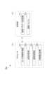
図3は、補償システム1における制御系統のハードウェア構成を示すブロック図である。
図3に示すように、補償システム1は、制御系統のハードウェア構成として、PCあるいはサーバコンピュータ等の情報処理装置によって構成される制御装置30と、マスタ装置10の制御ユニット101と、通信ユニット102と、挿入用アクチュエータ103と、検知用アクチュエータ104と、回転用アクチュエータ105と、操作用アクチュエータ106と、リニアエンコーダ107,108と、ロータリーエンコーダ109,110と、ドライバ111~114と、スレーブ装置20の制御ユニット201と、通信ユニット202と、挿入用アクチュエータ203と、検知用アクチュエータ204と、回転用アクチュエータ205と、操作用アクチュエータ206と、リニアエンコーダ207,208と、ロータリーエンコーダ209,210と、ドライバ211~214と、ディスプレイLと、カメラCと、を備えている。[Hardware configuration]
Next, the hardware configuration of the control system in the
FIG. 3 is a block diagram showing a hardware configuration of a control system in the
As shown in FIG. 3, the
マスタ装置10の制御ユニット101は、プロセッサ及びメモリ等を備えるマイクロコンピュータによって構成され、マスタ装置10の動作を制御する。例えば、制御ユニット101は、制御装置30から送信される制御パラメータに従って、マスタ装置10の挿入用アクチュエータ103、検知用アクチュエータ104、回転用アクチュエータ105及び操作用アクチュエータ106の駆動を制御する。
通信ユニット102は、ネットワーク40を介してマスタ装置10が他の装置との間で行う通信を制御する。 The
The
挿入用アクチュエータ103は、例えば直動型モータによって構成され、制御ユニット101の指示に従って、操作者がマスタ装置10に入力する、カテーテルを血管内に挿入していくために進退させる操作に対して、反力を付与する。
検知用アクチュエータ104は、例えばボイスコイルモータによって構成され、制御ユニット101の指示に従って、操作者がマスタ装置10に入力する、カテーテルを病変付近で処置のために進退させる操作に対して、反力を付与する。
本実施形態においては、挿入用アクチュエータ103の方が検知用アクチュエータ104に比べて長いストロークを有する一方、検知用アクチュエータ104の方が挿入用アクチュエータ103に比べて高精度な位置及び力の制御を行うことが可能となっている。
回転用アクチュエータ105は、例えば回転型モータによって構成され、制御ユニット101の指示に従って、操作者がマスタ装置10を進退方向に沿う回転軸周りに回転させる操作に対して、反力を付与する。
操作用アクチュエータ106は、例えば回転型モータによって構成され、制御ユニット101の指示に従って、操作者がエンドエフェクタを動作させるためのレバー(把持部)等に入力した操作に対して、反力を付与する。 The
The
In this embodiment, while the
The
The
リニアエンコーダ107は、挿入用アクチュエータ103の可動子の位置(直動軸における進退位置)を検出する。
リニアエンコーダ108は、検知用アクチュエータ104の可動子の位置(直動軸における進退位置)を検出する。
ロータリーエンコーダ109は、回転用アクチュエータ105の可動子の位置(回転角度)を検出する。
ロータリーエンコーダ110は、操作用アクチュエータ106の可動子の位置(回転角度)を検出する。 The linear encoder 107 detects the position of the mover of the insertion actuator 103 (the advance/retract position on the linear axis).
The linear encoder 108 detects the position of the mover of the detection actuator 104 (the advance/retract position on the linear axis).
The rotary encoder 109 detects the position (rotation angle) of the mover of the
The rotary encoder 110 detects the position (rotation angle) of the mover of the
ドライバ111は、制御ユニット101の指示に従って、挿入用アクチュエータ103に駆動電流を出力する。
ドライバ112は、制御ユニット101の指示に従って、検知用アクチュエータ104に駆動電流を出力する。
ドライバ113は、制御ユニット101の指示に従って、回転用アクチュエータ105に駆動電流を出力する。
ドライバ114は、制御ユニット101の指示に従って、操作用アクチュエータ106に駆動電流を出力する。 The
The driver 112 outputs a drive current to the
The driver 113 outputs a drive current to the
The
判定用センサ115は、制御装置30が摩擦補償を行うか否かを判定するための物理量を測定する。本実施形態において、判定用センサ115は、マスタ装置10の操作者が、操作のためにマスタ装置10を把持しているか否かを判定するための圧力センサにより構成される。そして、判定用センサ115は、カテーテルであるマスタ装置10を操作する際に、操作者により把持される操作部に配置される共に、把持時と非把持時とで変動する圧力を感圧素子により計測して、電気信号に変換する。また、判定用センサ115は、変換後の電気信号を、マスタ装置10の操作部に加えられる圧力の変動を示す情報として制御装置30に送信する。
この場合に、判定用センサ115が配置される操作部の構造や、判定用センサ115の操作部における配置位置は特に限定されない。また、判定用センサ115の構造や、圧力の測定原理についても特に限定されない。ただし、操作者によるマスタ装置10への操作(ここでは、カテーテルを血管内に挿入していくために進退させる操作や、エンドエフェクタを動作させる操作)を阻害しない構造や配置位置等にすることが好ましい。 The
In this case, the structure of the operation section in which the
スレーブ装置20の制御ユニット201は、プロセッサ及びメモリ等を備えるマイクロコンピュータによって構成され、スレーブ装置20の動作を制御する。例えば、制御ユニット201は、制御装置30から送信される制御パラメータに従って、スレーブ装置20の挿入用アクチュエータ203、検知用アクチュエータ204、回転用アクチュエータ205及び操作用アクチュエータ206の駆動を制御する。
通信ユニット202は、ネットワーク40を介してスレーブ装置20が他の装置との間で行う通信を制御する。 The
The
挿入用アクチュエータ203は、例えば直動型モータによって構成され、制御ユニット201の指示に従って、操作者がマスタ装置10に入力した、カテーテルを血管内に挿入していくために進退させる操作に応じて、スレーブ装置20のカテーテルを進退させる。
検知用アクチュエータ204は、例えばボイスコイルモータによって構成され、制御ユニット201の指示に従って、操作者がマスタ装置10に入力した、カテーテルを病変付近で処置のために進退させる操作に応じて、スレーブ装置20のカテーテルを進退させる。
本実施形態においては、挿入用アクチュエータ203の方が検知用アクチュエータ204に比べて長いストロークを有する一方、検知用アクチュエータ204の方が挿入用アクチュエータ203に比べて高精度な位置及び力の制御を行うことが可能となっている。
回転用アクチュエータ205は、例えば回転型モータによって構成され、制御ユニット201の指示に従って、操作者がマスタ装置10に入力した操作に応じて、スレーブ装置20のカテーテルを進退方向に沿う回転軸周りに回転させる。
操作用アクチュエータ206は、例えば回転型モータによって構成され、制御ユニット201の指示に従って、操作者がマスタ装置10に入力した操作に応じて、エンドエフェクタを動作(拡張、収縮動作や開閉動作等)させる。 The
The
In this embodiment, while the
The
The
リニアエンコーダ207は、挿入用アクチュエータ203の可動子の位置(直動軸における進退位置)を検出する。
リニアエンコーダ208は、検知用アクチュエータ204の可動子の位置(直動軸における進退位置)を検出する。
ロータリーエンコーダ209は、回転用アクチュエータ205の可動子の位置(回転角度)を検出する。
ロータリーエンコーダ210は、操作用アクチュエータ206の可動子の位置(回転角度)を検出する。 The linear encoder 207 detects the position of the mover of the insertion actuator 203 (the advance/retract position on the linear axis).
The linear encoder 208 detects the position of the mover of the detection actuator 204 (the advance/retract position on the linear axis).
The rotary encoder 209 detects the position (rotation angle) of the mover of the
The rotary encoder 210 detects the position (rotation angle) of the mover of the
ドライバ211は、制御ユニット201の指示に従って、挿入用アクチュエータ203に駆動電流を出力する。
ドライバ212は、制御ユニット201の指示に従って、検知用アクチュエータ204に駆動電流を出力する。
ドライバ213は、制御ユニット201の指示に従って、回転用アクチュエータ205に駆動電流を出力する。
ドライバ214は、制御ユニット201の指示に従って、操作用アクチュエータ206に駆動電流を出力する。 The
The driver 212 outputs a drive current to the
The driver 213 outputs a drive current to the
The
ディスプレイLは、マスタ装置10の操作者が画面を視認できる場所に設置され、制御装置30によって表示を指示された画像(カメラCによって撮影された操作者の可視光画像や、被検体の可視光画像あるいはX線画像等)や、制御装置30によって表示を指示された情報を表示する。
カメラCは、スレーブ装置20がカテーテルを挿入する被検体を撮影可能な場所に設置され、被検体の画像(可視光画像あるいはX線画像等)を撮影し、撮影した画像を制御装置30に送信する。 The display L is installed in a location where the operator of the
Camera C is installed at a location where
図4は、制御装置30を構成する情報処理装置のハードウェア構成を示す模式図である。
図4に示すように、制御装置30は、プロセッサ311と、ROM(Read Only Memory)312と、RAM(Random Access Memory)313と、バス314と、入力部315と、出力部316と、記憶部317と、通信部318と、ドライブ319と、を備えている。 FIG. 4 is a schematic diagram showing the hardware configuration of an information processing device constituting the
As shown in FIG. 4 , the
プロセッサ311は、ROM312に記録されているプログラム、または、記憶部317からRAM313にロードされたプログラムに従って各種の処理を実行する。
RAM313には、プロセッサ311が各種の処理を実行する上において必要なデータ等も適宜記憶される。 The
The
プロセッサ311、ROM312及びRAM313は、バス314を介して相互に接続されている。バス314には、入力部315、出力部316、記憶部317、通信部318及びドライブ319が接続されている。The
入力部315は、各種ボタン等で構成され、指示操作に応じて各種情報を入力する。
出力部316は、ディスプレイやスピーカ等で構成され、画像や音声を出力する。
なお、制御装置30がスマートフォンやタブレット端末として構成される場合には、入力部315と出力部316のディスプレイとを重ねて配置し、タッチパネルを構成することとしてもよい。
記憶部317は、ハードディスクあるいはDRAM(Dynamic Random Access Memory)等で構成され、各サーバで管理される各種データを記憶する。
通信部318は、ネットワークを介して制御装置30が他の装置との間で行う通信を制御する。 The
The
In addition, when the
The
The
ドライブ319には、磁気ディスク、光ディスク、光磁気ディスク、あるいは半導体メモリ等よりなる、リムーバブルメディア331が適宜装着される。ドライブ319によってリムーバブルメディア331から読み出されたプログラムは、必要に応じて記憶部317にインストールされる。
[制御補償処理の概要]
次に、補償システム1により行われる補償制御処理の概要について説明する。
図5は、補償システム1により行われる補償制御処理の概要を示す模式図である。
まず図5(A)は、操作者が操作を行っておらず、マスタ装置10の操作部を把持していない状態(非把持時)に関するものである。非把持時において、マスタ装置10は操作者により支えられていない。そのため、模式的に図示するように、マスタ装置10に加えられる外力の影響に起因する振動が生じやすい。すなわち、非把持時は、把持時と比較して、相対的に操作者の意図しない振動が生じやすい。また、振動が生じた場合に、この振動の減衰要因がスレーブ装置20に対して被検体等から加えられる摩擦のみであるため、模式的に図示するように、振動が減衰しにくい。[Overview of control compensation processing]
Next, an overview of the compensation control process performed by the
FIG. 5 is a schematic diagram showing an overview of the compensation control process performed by the
5A relates to a state in which the operator is not performing any operation and is not gripping the operation unit of the master unit 10 (non-gripping state). In the non-gripping state, the
一方で、図5(B)は、操作者が操作を行うためにマスタ装置10の操作部を把持している状態(把持時)に関するものである。把持時において、マスタ装置10は操作者により支えられている。そのため、模式的に図示するように、マスタ装置10に加えられる外力の影響に起因する振動が生じにくいやすい。すなわち、把持時は、非把持時と比較して、相対的に操作者の意図しない振動が生じにくい。また、振動が生じた場合に、この振動の減衰要因として、スレーブ装置20に対して被検体等から加えられる摩擦のみならず、操作者の把持による把持抵抗があるため、模式的に図示するように、振動が減衰しやすい。On the other hand, FIG. 5(B) shows a state in which the operator is gripping the operation unit of the
そこで、補償システム1は、操作者によるマスタ装置10に対する操作の状態の判定として、操作者によりマスタ装置10が把持されている状態であるか否か判定する。そして、補償システム1は、判定結果が、操作者によりマスタ装置10が把持されている状態であるとの判定結果である場合に、摩擦補償を行うと決定する。
これにより、操作者が操作を行うためにマスタ装置10が把持されており、振動の発生しにくい状況の場合に、摩擦補償により適切に操作者をアシストすることができる。一方で、マスタ装置10が把持されていないという操作者へのアシストが不要な場合には、摩擦補償を行わないことにより、操作者が意図せず生じた振動を増幅してしまうことを防止することができる。
以上が補償制御処理の概要である。 Therefore, the
As a result, when the operator is holding the
The above is an outline of the compensation control process.
[機能的構成]
次に、補償システム1の機能的構成について説明する。
図6は、補償システム1の機能的構成を示すブロック図である。
図6に示すように、補償システム1では、制御装置30が各種処理を実行することにより、プロセッサ311において、センサ情報取得部351と、状態判定部352と、摩擦補償部353と、力触覚伝達部354と、が機能する。また、記憶部17には、制御パラメータ記憶部371が形成される。[Functional configuration]
Next, the functional configuration of the
FIG. 6 is a block diagram showing the functional configuration of the
6, in the
制御パラメータ記憶部371は、制御装置30がマスタ装置10とスレーブ装置20との間で力触覚を伝達する制御において取得された制御パラメータを時系列に記憶する。本実施形態において、制御パラメータとして記憶される情報は、力触覚の伝達制御で取得される種々のパラメータとすることが可能であり、力触覚の伝達制御が再現可能な各種情報含むことができる。例えば、マスタ装置10及びスレーブ装置20において取得されるセンサ情報、これらのセンサ情報を座標変換した状態値、各アクチュエータへの電流指令値あるいは力触覚の伝達制御のために制御装置30に設定される各種設定値等を制御パラメータとして記憶することができる。The control
センサ情報取得部351は、マスタ装置10及びスレーブ装置20に設置された各種センサによって検出されたセンサ情報を取得する。例えば、センサ情報取得部351は、リニアエンコーダ107,108,207,208及びロータリーエンコーダ109,110,209,210によって検出された各アクチュエータの可動子の位置(進退位置または回転角度)を示す情報を取得する。また、センサ情報取得部351は、判定用センサ115によって測定された、マスタ装置10の操作部に加えられる圧力の変動を示す情報を取得する。
そして、センサ情報取得部351は、これらの取得したセンサ情報を時系列のデータとして、制御パラメータ記憶部371に記憶する。 The sensor
Then, the sensor
状態判定部352は、操作者によるマスタ装置10に対する操作の状態として、操作者によりマスタ装置10の操作部が把持されている状態であるか否か判定する。状態判定部352は、判定用センサ115によって測定された、マスタ装置10の操作部に加えられる圧力の変動を示す情報に基づいて、マスタ装置10の操作部に対して加えられる圧力の変動を検出する。そして、状態判定部352は、変動する圧力が所定の基準を満たした場合に、操作者によりマスタ装置10の操作部が把持されている状態であると判定する。一方で、変動する圧力が所定の基準を満たしていない場合に、操作者によりマスタ装置10の操作部が把持されていない状態であると判定する。
ここで、この所定の基準は、例えば、変動した圧力の瞬時値がマスタ装置10の構造等に基づいて設定された閾値を超えたことや、閾値を超えた状態が所定時間以上継続したこととすることができる。
そして、状態判定部352は、この判定結果を摩擦補償部353に対して出力する。 The
Here, this specified criterion can be, for example, that the instantaneous value of the fluctuating pressure exceeds a threshold value set based on the structure of the
Then, the
摩擦補償部353は、状態判定部352の判定結果に基づいて摩擦補償を行うか否かを決定し、摩擦補償を行うと決定した場合には、スレーブ装置20に入力する力を所定の増幅率で増幅してマスタ装置10に伝達する制御を後述の力触覚伝達部354に行わせることで摩擦補償を行う。例えば、摩擦補償部353は、状態判定部352による判定結果が、操作者によりマスタ装置10が把持されている状態であるとの判定結果である場合に、摩擦補償を行うと決定する。The
まず、摩擦補償を行うと決定した場合、摩擦補償部353は、マスタ装置10において操作者に対して出力する摩擦補償量(操作をアシストするための力)を算出する。例えば、摩擦補償部353は、スレーブ装置20において検出される力と、予め設定された所定の増幅率(1より大きい任意の値)とを乗算することで摩擦補償量を算出する。そして、摩擦補償部353は、算出した摩擦補償量を力触覚伝達部354に対して出力する。この場合、所定の増幅率は、例えば、過去に被検体または被検体を模した生体モデルに対してカテーテルを挿入した際の、実測値、統計値またはシミュレーションにより得られる推定値等に基づいて設定することができる。また、この所定の増幅率は、固定された値であってもよいが、可変する値であってもよい。例えば、マスタ装置10及びスレーブ装置20を実現するデバイスの種類や、操作者の操作により実現する施術の種類や、操作者による設定指示や、スレーブ装置20の被検体への挿入状態等に基づいて、適切な値に可変されてもよい。First, when it is determined that friction compensation is to be performed, the
一方で、摩擦補償を行わないと決定した場合、摩擦補償部353は、摩擦補償量を算出することなく、スレーブ装置20において検出された力そのものを力触覚伝達部354に対して出力する。On the other hand, if it is decided not to perform friction compensation, the
力触覚伝達部354は、図2に示す制御アルゴリズム及び摩擦補償部353からの入力に従って、マスタ装置10及びスレーブ装置20における力触覚の伝達を制御する。なお、図2に示す制御アルゴリズムの説明として上述したように、力触覚伝達部354は、スレーブ装置20に入力した外力をマスタ装置10に拡大して伝達する場合、スレーブ装置20において検出された力を増幅(すなわち、拡大)してマスタ装置10に伝達することができる。The
まず、摩擦補償部353から摩擦補償量が入力された場合(すなわち、摩擦補償を行う場合)、力触覚伝達部354は、摩擦補償部353によって算出された摩擦補償量で、スレーブ装置20に入力する摩擦力を補償する制御を行う。すなわち、力触覚伝達部354は、所定の増幅率に基づいて算出された(すなわち、増幅された)摩擦補償量を、マスタ装置10における操作者の操作をアシストするための力としてマスタ装置10に伝達することにより摩擦補償を実現する。First, when a friction compensation amount is input from the friction compensation unit 353 (i.e., when friction compensation is performed), the force
一方で、摩擦補償部353から、スレーブ装置20において検出される力そのものが入力された場合(すなわち、摩擦補償を行わない場合)、スレーブ装置20において検出された力を、マスタ装置10に伝達する。すなわち、力が増幅(すなわち、拡大)や減衰(すなわち、縮小)することなく伝達される。On the other hand, when the force detected in the
[動作]
次に、補償システム1の動作を説明する。[Action]
Next, the operation of the
[補償制御処理]
図7は、制御装置30が実行する補償制御処理の流れを説明するフローチャートである。
補償制御処理は、操作者からの入力部315を介した補償制御処理の実行指示操作や、通信部318を介した外部装置(例えば、マスタ装置10)からの通信による補償制御処理の実行指示がなされることに対応して開始される。本実施形態において、補償制御処理を開始する場合、スレーブ装置20の動作を補助する補助者が手動により、または、マスタ装置10からの遠隔的な操作により、カテーテルの先端が所定距離だけ被検体に挿入された状態(例えば、1~10[cm]程度挿入された状態)において開始するものとする。これにより、挿入初期の外力の変化が大きい状態において、制御装置30の制御が不安定化することを抑制できる。[Compensation control process]
FIG. 7 is a flowchart illustrating the flow of the compensation control process executed by the
The compensation control process is started in response to an instruction to execute the compensation control process from the operator via the
ステップS11において、センサ情報取得部351は、マスタ装置10及びスレーブ装置20に設置された各種センサによって検出された情報(センサ情報)を取得する。ステップS11において取得されたセンサ情報は、時系列のデータとして制御パラメータ記憶部371に記憶される。In step S11, the sensor
ステップS12において、力触覚伝達部354は、操作者によるマスタ装置10に対する操作の状態として、操作者によりマスタ装置10の操作部が把持されている状態であるか否か判定する。In step S12, the force
ステップS13において、摩擦補償部353は、状態判定部352の判定結果に基づいて摩擦補償を行うか否かを決定する。摩擦補償を行うと決定した場合は、ステップS13においてYesと判定され、処理はステップS14に進む。一方で、摩擦補償を行わないと決定した場合は、ステップS13においてNoと判定され、処理はステップS16に進む。In step S13, the
ステップS14において、摩擦補償部353は、マスタ装置10において操作者に対して出力する摩擦補償量(操作をアシストするための力)を算出する。In step S14, the
ステップS15において、力触覚伝達部354は、ステップS14にて算出された摩擦補償量に基づいた摩擦補償をしながら、マスタ装置10及びスレーブ装置20における力触覚の伝達を制御する。In step S15, the
ステップS16において、ステップS16において、力触覚伝達部354は、摩擦補償をせずに、マスタ装置10及びスレーブ装置20における力触覚の伝達を制御する。In step S16, the force-
ステップS17において、力触覚伝達部354は、補償制御処理の終了が指示されたか否かの判定を行う。補償制御処理の終了が指示された場合は、ステップS17においてYesと判定され、補償制御処理は終了する。一方で、補償制御処理の終了が指示されていない場合は、ステップS17においてNoと判定され、処理はステップS11に戻り繰り返される。In step S17, the force
以上説明した補償制御処理によれば、補償システム1は、力触覚の伝達時に摩擦補償を行うに際し、操作者によるマスタ装置10に対する操作の状態に基づいて摩擦補償を行うか否かを決定する。すなわち、摩擦力の補償を常時行うのではなく、操作の状態に対応した適切なタイミングで摩擦補償を行う。これにより、例えば、摩擦力の補償を常時行ったことにより、操作者が意図せず生じた振動が増幅してしまうような不具合の発生を防止することができる。
従って、補償システム1によれば、より適切な状況で、摩擦補償を行う、という課題を解決することができる。 According to the compensation control process described above, when performing friction compensation during transmission of haptic sensation, the
Therefore, the
[変形例1]
上述の実施形態において、判定用センサ115は、マスタ装置10の操作者が、操作のためにマスタ装置10を把持しているか否かを判定するための圧力センサにより構成されるものとして説明した。これに限らず、他のセンサにより判定用センサ115を構成するようにしてもよい。例えば、圧力センサに代えて、温度センサによって判定用センサ115を構成するようにしてもよい。[Modification 1]
In the above embodiment, the
そして、判定用センサ115は、カテーテルであるマスタ装置10を操作する際に、操作者により把持される操作部に配置される共に、把持時と非把持時とで変動する温度を計測して、電気信号に変換する。また、判定用センサ115は、変換後の電気信号を、マスタ装置10の操作部に加えられる温度の変動を示す情報として制御装置30に送信する。The
この場合に、判定用センサ115が配置される操作部の構造や、判定用センサ115の操作部における配置位置は特に限定されない。また、判定用センサ115の構造や、温度の測定原理についても特に限定されない。さらに、判定用センサ115は接触式のものであってもよいし、非接触式のものであってもよい。また、判定用センサ115を非接触式の温度センサとする場合、判定用センサ115は必ずしも操作部に配置される必要はなく、操作部近傍の非接触で操作者の温度を測定できる位置に配置されてもよい。
ただし、操作者によるマスタ装置10への操作(ここでは、カテーテルを血管内に挿入していくために進退させる操作や、エンドエフェクタを動作させる操作)を阻害しない構造や配置位置等にすることが好ましい。 In this case, the structure of the operation unit in which the
However, it is preferable that the structure and the positioning, etc. be such that they do not impede the operator's operations on the master device 10 (here, the operation of moving the catheter forward and backward to insert it into a blood vessel, and the operation of operating the end effector).
また、上述の実施形態では、状態判定部352は、変動する圧力が所定の基準を満たした場合に、操作者によりマスタ装置10の操作部が把持されている状態であると判定した。これに対して、本変形例では、状態判定部352は、変動する温度が所定の基準を満たした場合に、操作者によりマスタ装置10の操作部が把持されている状態であると判定する。この所定の基準は、変動した温度の瞬時値が、人体の手の温度に近い閾値(すなわち、絶対値)の温度を超えたことや、この閾値を超えた状態が所定時間以上継続したこととすることができる。なお、温度は室温の影響も受けるので、例えば、計測開始時の温度(すなわち、室温に近い温度)から、所定値以上の温度を閾値(すなわち、相対値)としてもよい。
本変形例によれば、補償システム1に含まれるマスタ装置10の形状等の実装条件にて圧力センサが不適当な場合等に、圧力センサに代えて温度センサを利用することが可能となる。 In the above embodiment, the
According to this modification, when a pressure sensor is inappropriate due to mounting conditions such as the shape of the
[変形例2]
上述の実施形態や第1の変形例において、判定用センサ115を圧力センサや温度センサで構成し、この判定用センサ115の測定した圧力や温度に基づいて、マスタ装置10の操作者が、操作のためにマスタ装置10を把持しているか否かを判定していた。これに限らず、判定用センサ115の測定した情報ではなく、例えば、画像の解析結果に基づいて、マスタ装置10の操作者が、操作のためにマスタ装置10を把持しているか否かを判定してもよい。なお、本変形例2を実現する場合、マスタ装置10において判定用センサ115を省略した構成とすることも可能である。[Modification 2]
In the above-described embodiment and the first modified example, the
上述したように、補償システム1は、複数のカメラCを適宜備えることが可能である。そこで、例えば、カメラCとして、マスタ装置10を操作する操作者の外観(例えば、マスタ装置10に対する操作の状態)を撮影するビデオカメラを備える。この場合、状態判定部352は、このカメラCにより撮影された画像を、既存の画像解析の手法により解析する。そして、その解析結果に基づいて、マスタ装置10の操作者が、操作のためにマスタ装置10を把持しているか否かを判定する。As described above, the
あるいは、カメラCとして、X線により被検体の内部(例えば、被検体の血管や臓器)を撮影するX線カメラを備える。この場合、状態判定部352は、このカメラCにより撮影された画像を、既存の異常検出アルゴリズムの手法により解析する。例えば、異常検出アルゴリズムにより、マスタ装置10の操作者が、操作のためにマスタ装置10を把持している場合を正常とし、非把持の場合を異常として検出する。この解析結果に基づいて、マスタ装置10の操作者が、操作のためにマスタ装置10を把持しているか否かを判定する。
なお、何れの場合にも、例えば、機械学習の手法を組み合わせ、予め学習を行うことにより、画像解析の精度を高くするようにしてもよい。 Alternatively, the camera C may be an X-ray camera that captures images of the inside of the subject (e.g., blood vessels and organs of the subject) using X-rays. In this case, the
In either case, for example, a machine learning technique may be combined and learning may be performed in advance to improve the accuracy of image analysis.
[変形例3]
上述の実施形態では、摩擦補償部353は、摩擦補償を行うと決定した場合には、スレーブ装置20に入力する力を所定の増幅率で増幅してマスタ装置10に伝達する制御を後述の力触覚伝達部354に行わせることで摩擦補償を行っていた。これに限らず、所定の増幅率を動的に変動するようにしてもよい。[Modification 3]
In the above embodiment, when the
図8は、本変形例3における補償システム1の機能的構成を示すブロック図である。
図8に示すように、本変形例における制御装置30(以下では、「制御装置30a」と称すると共に、図面においても「制御装置30a」として示す。)では、上述した実施形態の制御装置30と比較して、さらに記憶部17に、速度バッファ372が形成される。また、摩擦補償部353における処理内容が異なる。
なお、速度バッファ372及び摩擦補償部353以外の他の機能的構成(すなわち、機能ブロック)については、図6を参照して説明した機能的構成と同じであるので、重複する説明を省略する。 FIG. 8 is a block diagram showing a functional configuration of the
8, in comparison with the
In addition, the functional configuration (i.e., functional blocks) other than the
速度バッファ372は、過去の設定された区間(例えば、過去5秒)において、摩擦補償部353によって算出されたカテーテルの進退速度のデータを記憶する。速度バッファ372に記憶されるカテーテルの進退速度のデータは、摩擦補償部353が新たにカテーテルの進退速度を算出する毎に、最新のデータに逐次更新される。The
摩擦補償部353は、センサ情報取得部351によって取得されたセンサ情報(ここでは、リニアエンコーダ107,108,207,208及びロータリーエンコーダ109,110,209,210によって検出された各アクチュエータの可動子の位置(進退位置または回転角度)を示す情報)に基づいて、スレーブ装置20におけるカテーテルの現在の進退速度(現在値)を算出する。また、摩擦補償部353は、算出したカテーテルの現在の進退速度(現在値)を時刻と対応付けて、速度バッファ372に記憶する。そして、摩擦補償部353は、過去の設定された区間におけるカテーテルの進退速度の平均値(すなわち、移動平均値)を算出し、算出した移動平均値と摩擦補償のために設定された摩擦補償係数とを乗算することにより、マスタ装置10においてユーザに対して出力する摩擦補償量(操作をアシストするための力)を算出する。なお、移動平均値として、ここでは、単純移動平均値を用いることとする。The
ここで、カテーテルは弾性を有するものであるため、例えば、操作者が不意に接触する等の一過性のノイズでスレーブ装置20に外力が入力すると、入力に対してカテーテルの弾性力が作用し、カテーテルが押し返されることになる。
このとき、単純に摩擦補償を行った場合、カテーテルの動作が増幅されることになり、単振動が発生することとなる。
また、スレーブ装置20に外力が入力していない場合であっても、センサによって進退方向に微小な速度が検出されることがあり、単純な摩擦補償を行った場合、この微小な速度に対して摩擦補償が行われる。すると、進退方向の動作がアシストされ、単振動が発生することとなる。 Here, since the catheter has elasticity, when an external force is input to the
In this case, if friction compensation is simply performed, the movement of the catheter will be amplified, resulting in the generation of simple harmonic motion.
Even when no external force is being applied to the
これに対し、過去の設定された区間におけるカテーテルの進退速度の平均値(すなわち、移動平均値)に対して摩擦補償係数が乗算された摩擦補償量を、マスタ装置10におけるユーザの操作をアシストするための力として出力することで、カテーテルが振動する速度成分に対しては、アシストする力が付与されないと共に、カテーテルが一方向に移動する速度成分に対しては、アシストする力が付与されることとなる。
この結果、マスタ装置10を操作するユーザの負荷を低減しつつ、スレーブ装置20の状態変化を知覚させ易くすることができると共に、操作をアシストするための力によって、カテーテルに単振動が発生する事態を抑制することができる。
したがって、補償システム1において実行される摩擦補償のための制御をより適切なものとすることができる。 In contrast to this, by outputting a friction compensation amount obtained by multiplying the average value (i.e., moving average value) of the catheter advancement/retraction speed in a previously set section by a friction compensation coefficient as a force to assist the user's operation in the
As a result, it is possible to reduce the burden on the user who operates the
Therefore, the control for friction compensation executed in the
図9は、本変形例3における制御装置30aが実行する補償制御処理の流れを説明するフローチャートである。
なお、ステップS11、ステップS12、ステップS13、ステップS14、及びステップS15においては、図6を参照して説明した、同名のステップと同じ処理であるので、重複する説明を省略する。 FIG. 9 is a flowchart illustrating the flow of compensation control processing executed by the
In addition, steps S11, S12, S13, S14, and S15 are the same processes as the steps with the same names that were explained with reference to FIG. 6, so duplicate explanations will be omitted.
ステップS21において、摩擦補償部353は、ステップS11にてセンサ情報取得部351によって取得されたセンサ情報に基づいて、スレーブ装置20におけるカテーテルの現在の進退速度(現在値)を算出する。In step S21, the
ステップS22において、摩擦補償部353は、ステップS21にて算出したカテーテルの現在の進退速度(現在値)を時刻と対応付けて、速度バッファ372に記憶する。In step S22, the
ステップS23において、摩擦補償部353は、ステップS22にて速度バッファ372に記憶したデータに基づいて、過去の設定された区間におけるカテーテルの進退速度の平均値(すなわち、移動平均値)を算出する。In step S23, the
ステップS24において、摩擦補償部353は、ステップS23にて算出した移動平均値と摩擦補償のために設定された摩擦補償係数とを乗算することにより、マスタ装置10においてユーザに対して出力する摩擦補償量を算出する。In step S24, the
図10は、カテーテルの速度と摩擦補償量との関係を示す模式図である。
図10においては、(a)カテーテルの振動が発生している場合の速度の原波形、(b)カテーテルの振動が発生している場合の速度の移動平均値(原波形の10[Hz]以上を打ち消した波形)、(c)速度の原波形から算出した摩擦補償量、(d)速度の移動平均値から算出した摩擦補償量が示されている。なお、図10に示す波形は、正規化された速度または摩擦補償量の時間変化を示している。 FIG. 10 is a schematic diagram showing the relationship between the catheter speed and the amount of friction compensation.
10 shows (a) the original waveform of the velocity when the catheter is vibrating, (b) the moving average value of the velocity when the catheter is vibrating (a waveform in which 10 [Hz] or more of the original waveform is cancelled), (c) the friction compensation amount calculated from the original velocity waveform, and (d) the friction compensation amount calculated from the moving average value of the velocity. Note that the waveforms shown in FIG. 10 show the time change of the normalized velocity or the friction compensation amount.
図10(c)に示すように、カテーテルの振動が発生している場合の速度の原波形から単純に摩擦補償量を算出すると、カテーテルの振動を維持あるいは増大させる作用が働き、振動が長時間維持されることになる。
一方、図10(d)に示すように、カテーテルの振動が発生している場合の速度の移動平均値から摩擦補償量を算出すると、カテーテルの振動を維持あるいは増大させる作用が低減されていることがわかる。 As shown in FIG. 10(c), if the friction compensation amount is simply calculated from the original velocity waveform when the catheter is vibrating, an effect will be exerted which maintains or increases the vibration of the catheter, resulting in the vibration being maintained for a long period of time.
On the other hand, as shown in FIG. 10(d), when the friction compensation amount is calculated from the moving average value of the speed when the catheter is vibrating, it can be seen that the effect of maintaining or increasing the catheter vibration is reduced.
以上のように、本変形例3における補償システム1は、過去の設定された区間におけるカテーテルの進退速度の平均値(すなわち、移動平均値)に対して摩擦補償係数が乗算された摩擦補償量を、マスタ装置10におけるユーザの操作をアシストするための力として出力する。この結果、カテーテルが振動する速度成分に対しては、アシストする力が付与されないと共に、カテーテルが一方向に移動する速度成分に対しては、アシストする力が付与されることとなる。As described above, the
これにより、スレーブ装置20に入力する摩擦力を補償する場合に、マスタ装置10を操作するユーザの負荷を低減しつつ、スレーブ装置20の状態変化を知覚させ易くすることができると共に、操作をアシストするための力によって、カテーテルに単振動が発生する事態を抑制することができる。
したがって、補償システムにおいて実行される摩擦補償のための制御をより適切なものとすることができる。 As a result, when compensating for the frictional force input to the
Therefore, the control for friction compensation executed in the compensation system can be made more appropriate.
[変形例4]
上述の変形例3をさらに変形するようにしてもよい。例えば、所定の増幅率を動的に変動するに際して、忘却係数を用いるようにしてもよい。変形例3においては、過去の設定された区間におけるカテーテルの進退速度の平均値(すなわち、移動平均値)に対して摩擦補償係数が乗算された摩擦補償量を、マスタ装置10におけるユーザの操作をアシストするための力として出力するものとした。
これに対し、本変形例においては、過去の設定された区間におけるカテーテルの進退速度の平均値(すなわち、移動平均値)を算出する際に、現在時刻に近い時刻の進退速度ほど、高い重みを設定した忘却係数を乗算することで、忘却特性を有する進退速度の移動平均値を算出する。
これにより、スレーブ装置20における外力の状態に変化が生じた場合に、その変化をより速やかに反映させて、摩擦補償を行うことが可能となる。[Modification 4]
The above-mentioned modified example 3 may be further modified. For example, a forgetting factor may be used when dynamically varying the predetermined amplification factor. In the modified example 3, a friction compensation amount obtained by multiplying the average value (i.e., moving average value) of the catheter advancement/retraction speed in a set section in the past by a friction compensation coefficient is output as a force for assisting the user's operation of the
In contrast, in this modified example, when calculating the average value (i.e., the moving average value) of the catheter advancement/retraction speed in a set section in the past, the advancement/retraction speed at a time closer to the current time is multiplied by a forgetting coefficient with a higher weighting, thereby calculating the moving average value of the advancement/retraction speed having forgetting characteristics.
As a result, when a change occurs in the state of the external force on the
本変形例における補償システム1は、変形例3における補償システム1に対し、摩擦補償部353における処理内容が異なっている。
したがって、以下、異なる部分である摩擦補償部353における処理内容を主として説明する。 The
Therefore, the following mainly describes the processing contents in the
摩擦補償部353は、センサ情報取得部351によって取得されたセンサ情報に基づいて、スレーブ装置20におけるカテーテルの現在の進退速度(現在値)を算出する。また、摩擦補償部353は、算出したカテーテルの現在の進退速度(現在値)を時刻と対応付けて、速度バッファ372に記憶する。そして、摩擦補償部353は、過去の設定された区間におけるカテーテルの進退速度に対し、忘却係数に基づく重みづけ平均値(以下、「忘却係数付き移動平均値」と称する。)を算出し、算出した忘却係数付き移動平均値と摩擦補償のために設定された摩擦補償係数とを乗算することにより、マスタ装置10においてユーザに対して出力する摩擦補償量(操作をアシストするための力)を算出する。The
なお、変形例3における過去の設定された区間におけるカテーテルの進退速度の移動平均値は、例えば、次式(5)で表される。
これに対し、本変形例において、過去の設定された区間におけるカテーテルの進退速度に対し、忘却係数付き移動平均値を算出する場合、次式(6)によって算出することができる。 In addition, the moving average value of the catheter advancement/retraction speed in the past set section in the third modification is expressed, for example, by the following equation (5).
In contrast to this, in this modified example, when calculating a moving average value with a forgetting factor for the catheter advancement/retraction speed in a previously set section, the calculation can be performed by the following equation (6).

なお、式(5)及び(6)において、mは移動平均区間のデータ数、nは現在値のデータ番号、kは現在値から遡るデータの数、Tは時定数、exp(-k/T)は忘却係数を示している。時定数Tは、例えば、単純移動平均を用いて摩擦補償量を算出した場合の補償システム1の挙動等を基に、実験値あるいはシミュレーションにより得られた値等を参照して、適切な値を決定することができる。
式(6)に示す忘却係数付き移動平均値の算出は、カテーテルの進退速度の波形に一次IIRローパスフィルタを適用する演算に相当する。 In the formulas (5) and (6), m is the number of data in the moving average interval, n is the data number of the current value, k is the number of data going back from the current value, T is a time constant, and exp(-k/T) is a forgetting coefficient. An appropriate value for the time constant T can be determined by referring to experimental values or values obtained by simulation, based on the behavior of the
The calculation of the moving average value with a forgetting factor shown in equation (6) corresponds to a calculation of applying a first-order IIR low-pass filter to the waveform of the catheter advancement/retraction speed.
図11は、式(6)に示す忘却係数付き移動平均値の忘却係数を示す模式図である。
図11に示すように、忘却係数付き移動平均値を算出する際に用いられる忘却係数は、現在時刻に近い時刻ほど大きい値となり、現在時刻から離れた過去の時刻ほど小さい値となる。
力触覚伝達部354は、このように算出された摩擦補償量を用いて、変形例3と同様に、スレーブ装置20に入力する摩擦力を補償する制御を行う。 FIG. 11 is a schematic diagram showing the forgetting factor of the moving average value with forgetting factor shown in equation (6).
As shown in FIG. 11, the forgetting factor used in calculating the moving average with forgetting factor has a larger value the closer the time is to the current time, and a smaller value the further back in time is from the current time.
The haptic
以上のように、本変形例4における補償システム1は、過去の設定された区間におけるカテーテルの進退速度に対する忘却係数付き移動平均値を算出し、忘却係数付き移動平均値と摩擦補償のために設定された摩擦補償係数とを乗算することにより、マスタ装置10においてユーザに対して出力する摩擦補償量を算出する。そして、このように算出した摩擦補償量を、マスタ装置10におけるユーザの操作をアシストするための力として出力する。この結果、カテーテルが振動する速度成分に対しては、アシストする力が付与されないと共に、カテーテルが一方向に移動する速度成分に対しては、アシストする力が付与されることとなる。さらに、忘却係数付き移動平均値の特性により、カテーテルの進退速度のデータのうち、過去のものほど重みを小さくして移動平均値が算出されるため、現在のカテーテルの進退速度に対応する摩擦力を補償する作用が高くなる。As described above, the
これにより、スレーブ装置20に入力する摩擦力を補償する場合に、マスタ装置10を操作するユーザの負荷を低減しつつ、スレーブ装置20の状態変化を知覚させ易くすることができると共に、操作をアシストするための力によって、カテーテルに単振動が発生する事態を抑制することができる。また、一過性のノイズでスレーブ装置20に外力が入力した場合であっても、その外力に起因したカテーテルの進退をアシストする力と、カテーテルの弾性力とが釣り合うことにより、カテーテルが振動の途中で一時的に静止した状態となること等を抑制することができる。すなわち、移動平均値に忘却係数を乗じることで、摩擦補償量が一定とならない(忘却係数の作用により常時変化する)ため、移動平均区間において、一過性のノイズに基づく外力が入力することで生じる定常的な力と、特定位置でのカテーテルの弾性力とが釣り合うことで静止する状態が発生し難くなる。また、移動平均値に忘却係数を乗じることで算出された摩擦補償量の振動する成分は、移動平均の効果により低減されるため、カテーテルに振動が発生する事態をさらに抑制することができる。
したがって、補償システム1において実行される摩擦補償のための制御をより適切なものとすることができる。 As a result, when the friction force input to the
Therefore, the control for friction compensation executed in the
[変形例5]
上述の変形例4や変形例5をさらに変形するようにしてもよい。例えば、進退速度以外の要素を加味して、摩擦補償量を算出するようにしてもよい。上述の変形例4や変形例5において、スレーブ装置20であるカテーテルの進退速度に対して、マスタ装置10における摩擦補償のための力(操作をアシストするための力)を出力するものとして説明した。
これに対し、カテーテルの進退速度以外の要素を加味して、摩擦補償のための力を出力することができる。
例えば、スレーブ装置20が設置されている角度によって、進退動作に対して定常的に重力の影響が生じるため、重力に対して、マスタ装置10における操作をアシストするための力(傾斜補償のための力)を出力することができる。[Modification 5]
The above-described modified example 4 and modified example 5 may be further modified. For example, the friction compensation amount may be calculated taking into account factors other than the advancement/retraction speed. In the above-described modified example 4 and modified example 5, a force for friction compensation (a force for assisting an operation) in the
In response to this, a force for compensating for friction can be output taking into account factors other than the advancement and retraction speed of the catheter.
For example, since gravity constantly affects the forward and backward movement depending on the angle at which the
この場合、例えば、摩擦補償部353が、スレーブ装置20が設置されている傾斜角度を基に、カテーテルの進退方向において作用する重力の成分を算出すると共に、算出した重力の成分に対応する傾斜補償のための力を算出(重力の成分に係数を乗じる等)し、力触覚伝達部354が、マスタ装置10において、傾斜補償のための力をアシストすることができる。このとき、カテーテルの進退方向において、重力の成分と同方向にはマイナスのアシスト(すなわち、重力の成分がカテーテルを移動させる作用を妨げる力)を出力すると共に、重力の成分と逆方向にはプラスのアシスト(重力の成分がカテーテルの移動を阻害する作用を抑制する力)を出力することができる。In this case, for example, the
これにより、スレーブ装置20に入力する重力の影響を補償し、マスタ装置10を操作するユーザの負荷を低減しつつ、スレーブ装置20の状態変化(実際の負荷の大きさ等)を知覚させ易くすることができる。
したがって、補償システム1において実行される摩擦補償のための制御をより適切なものとすることができる。 This compensates for the effect of gravity input to the
Therefore, the control for friction compensation executed in the
[他の変形例]
上述の実施形態において、マスタ装置10とスレーブ装置20との間で、カテーテルのスラスト方向(進退方向)の力を力触覚伝達するものとして説明したが、これに限られない。例えば、進退方向に沿う回転軸周りの回転、あるいは、エンドエフェクタの操作に関する力をマスタ装置10とスレーブ装置20との間で力触覚伝達してもよい。さらに、例えば、上述の実施形態において、補償システム1によってカテーテルを遠隔的に操作する場合を例に挙げて説明したが、これに限られない。すなわち、補償システム1によって遠隔的に操作される機器として、種々のものを対象とすることが可能であり、例えば、線状に構成された部分を有する各種機器、一例として、鉗子あるいは内視鏡等の医療機器を対象とすることができる。[Other Modifications]
In the above embodiment, the force in the thrust direction (advance/retract direction) of the catheter is described as being transmitted between the
また、上述の実施形態において、マスタ装置10に備えられたアクチュエータと、スレーブ装置20に備えられたアクチュエータとを1対1に対応付けて、力触覚の伝達を行う場合を例に挙げて説明したが、これに限られない。すなわち、マスタ装置10の複数のアクチュエータをスレーブ装置20の1つのアクチュエータと対応付けて力触覚の伝達を行ったり、マスタ装置10の1つのアクチュエータをスレーブ装置20の複数のアクチュエータと対応付けて力触覚の伝達を行ったりすることが可能である。また、マスタ装置10の複数のアクチュエータをスレーブ装置20の複数のアクチュエータと対応付けて力触覚の伝達を行うことも可能である。一例として、図3に示すスレーブ装置20の挿入用アクチュエータ203及び検知用アクチュエータ204を、マスタ装置10の挿入用アクチュエータ103を対応付けて力触覚の伝達を行うことが可能である。この場合、マスタ装置10の検知用アクチュエータ104を備える必要がなくなり、コストの削減及び装置の軽量化等を実現することができる。In the above embodiment, the actuators provided in the
[構成例]
以上のように、本実施形態に係る補償システム1は、操作者の操作が入力されるマスタ装置10と、マスタ装置10に入力された操作に応じて動作するスレーブ装置20と、を含む。また、補償システム1は、力触覚伝達部354と、状態判定部352と、摩擦補償部353と、を備える。
力触覚伝達部354は、マスタ装置10及びスレーブ装置20における力触覚の伝達を制御する。
状態判定部352は、操作者によるマスタ装置10に対する操作の状態を判定する。
摩擦補償部353は、状態判定部352による判定結果に基づいて摩擦補償を行うか否かを決定し、摩擦補償を行うと決定した場合には、力触覚伝達部354による力触覚の伝達に影響する摩擦に対して摩擦補償を行う。
このように、補償システム1は、力触覚の伝達時に摩擦補償を行うに際し、操作者によるマスタ装置10に対する操作の状態に基づいて摩擦補償を行うか否かを決定する。すなわち、摩擦力の補償を常時行うのではなく、操作の状態に対応した適切なタイミングで摩擦補償を行う。これにより、例えば、摩擦力の補償を常時行ったことにより、操作者が意図せず生じた振動が増幅してしまうような不具合の発生を防止することができる。
従って、補償システム1によれば、より適切な状況で、摩擦補償を行う、という課題を解決することができる。 [Configuration example]
As described above, the
The
The
The
In this way, when performing friction compensation during transmission of haptic sensation, the
Therefore, the
状態判定部352は、操作者によるマスタ装置10に対する操作の状態の判定として、操作者によりマスタ装置10が把持されている状態であるか否か判定する。
摩擦補償部353は、状態判定部352による判定結果が、操作者によりマスタ装置10が把持されている状態であるとの判定結果である場合に、摩擦補償を行うと決定する。
これにより、操作者が操作を行うためにマスタ装置10が把持されており、振動の発生しにくい状況の場合に、摩擦補償により適切に操作者をアシストすることができる。一方で、マスタ装置10が把持されていないという操作者へのアシストが不要な場合には、摩擦補償を行わないことにより、操作者が意図せず生じた振動を増幅してしまうことを防止することができる。 The
The
As a result, when the operator is holding the
摩擦補償部353は、スレーブ装置に入力する力を所定の増幅率で増幅してマスタ装置10に伝達する制御を力触覚伝達部354に行わせることで摩擦補償を行う。
これにより、力触覚の伝達のための制御アルゴリズムを利用して、摩擦補償を行うことができる。 The
This allows friction compensation to be performed using a control algorithm for the transmission of haptic sensations.
状態判定部352は、マスタ装置10に対して加えられる圧力の変動に基づいて、操作者によるマスタ装置10に対する操作の状態を判定する。
これにより、把持時と非把持時とで変動する圧力に基づいて、操作者によるマスタ装置10に対する操作の状態を精度高く判定することができる。 The
This makes it possible to accurately determine the state of operation of the
状態判定部352は、マスタ装置10の温度の変動に基づいて、操作者によるマスタ装置10に対する操作の状態を判定する。
これにより、把持時と非把持時とで変動する温度に基づいて、操作者によるマスタ装置10に対する操作の状態を精度高く判定することができる。 The
This makes it possible to accurately determine the state of operation of the
状態判定部352は、操作者の操作に関する撮影画像を解析すると共に、該解析の結果に基づいて、操作者によるマスタ装置10に対する操作の状態を判定する。
これにより、マスタ装置10に加えられる圧力や温度を測定することなく、操作者によるマスタ装置10に対する操作の状態を精度高く判定することができる。 The
This makes it possible to determine with high accuracy the state of operation of the
以上のように、本実施形態に係る制御装置30は、力触覚伝達部354と、状態判定部352と、摩擦補償部353と、を備える。
力触覚伝達部354は、操作者の操作が入力されるマスタ装置10と、マスタ装置10に入力された操作に応じて動作するスレーブ装置20とにおける力触覚の伝達を制御する。
状態判定部352は、操作者によるマスタ装置10に対する操作の状態を判定する。
摩擦補償部353は、状態判定部352による判定結果に基づいて摩擦補償を行うか否かを決定し、摩擦補償を行うと決定した場合には、力触覚伝達部354による力触覚の伝達に影響する摩擦に対して摩擦補償を行う。
このような制御装置30の構成によっても、上述の補償システム1と同様に、より適切な状況で、摩擦補償を行う、という課題を解決することができる。 As described above, the
The
The
The
With such a configuration of the
なお、本発明は、上述の実施形態に限定されるものではなく、本発明の目的を達成できる範囲での変形、改良等は本発明に含まれるものである。
例えば、本発明は、上述の実施形態における補償システム1として実現することの他、補償システム1を制御する制御装置、補償システム1において実行される各ステップによって構成される制御方法、あるいは、補償システム1の機能を実現するためにプロセッサによって実行されるプログラムとして実現することができる。
また、上述の実施形態では、制御装置30を独立した装置として実現する構成を例に挙げて説明したが、制御装置30の機能をマスタ装置10の制御ユニット101及びスレーブ装置20の制御ユニット201の一方に実装したり、これらの両方に分散して実装したりすることができる。 The present invention is not limited to the above-described embodiment, and modifications and improvements within the scope of the present invention that can achieve the object of the present invention are included in the present invention.
For example, in addition to being realized as the
In addition, in the above-described embodiment, an example has been described in which the
また、上述の実施形態における処理は、ハードウェア及びソフトウェアのいずれにより実行させることも可能である。
すなわち、上述の処理を実行できる機能が補償システム1に備えられていればよく、この機能を実現するためにどのような機能構成及びハードウェア構成とするかは上述の例に限定されない。
上述の処理をソフトウェアにより実行させる場合には、そのソフトウェアを構成するプログラムが、コンピュータにネットワークや記憶媒体からインストールされる。 Furthermore, the processes in the above-described embodiments can be executed by either hardware or software.
In other words, it is sufficient that the
When the above-mentioned processes are executed by software, the programs constituting the software are installed into the computer from a network or a storage medium.
プログラムを記憶する記憶媒体は、装置本体とは別に配布されるリムーバブルメディア、あるいは、装置本体に予め組み込まれた記憶媒体等で構成される。リムーバブルメディアは、例えば、半導体メモリ、磁気ディスク、光ディスク、または光磁気ディスク等により構成される。光ディスクは、例えば、CD-ROM(Compact Disk-Read Only Memory),DVD(Digital Versatile Disk),Blu-ray Disc(登録商標)等により構成される。光磁気ディスクは、MD(Mini-Disk)等により構成される。また、装置本体に予め組み込まれた記憶媒体は、例えば、プログラムが記憶されているROM(Read Only Memory)やハードディスク、あるいは、半導体メモリ等で構成される。The storage medium that stores the program is composed of removable media distributed separately from the device body, or storage media that is pre-installed in the device body. Removable media is composed of, for example, semiconductor memory, magnetic disks, optical disks, or magneto-optical disks. Optical disks are composed of, for example, CD-ROMs (Compact Disk-Read Only Memory), DVDs (Digital Versatile Disks), Blu-ray Discs (registered trademark), etc. Magneto-optical disks are composed of, for example, MDs (Mini-Disks), etc. Also, storage media pre-installed in the device body is composed of, for example, ROMs (Read Only Memory) or hard disks in which the program is stored, or semiconductor memories, etc.
なお、上記実施形態は、本発明を適用した一例を示しており、本発明の技術的範囲を限定するものではない。すなわち、本発明は、本発明の要旨を逸脱しない範囲で、省略や置換等種々の変更を行うことができ、上記実施形態以外の各種実施形態を取ることが可能である。本発明が取ることができる各種実施形態及びその変形は、特許請求の範囲に記載された発明とその均等の範囲に含まれる。The above embodiment shows an example of the application of the present invention, and does not limit the technical scope of the present invention. In other words, the present invention can be modified in various ways, such as by omission or substitution, without departing from the gist of the present invention, and various embodiments other than the above embodiment can be adopted. The various embodiments and modifications that the present invention can adopt are included in the scope of the invention described in the claims and their equivalents.
1 補償システム、10 マスタ装置、20 スレーブ装置、30 制御装置、40 ネットワーク、L ディスプレイ、C カメラ、FT 機能別力・速度割当変換ブロック、FC 理想力源ブロック、PC 理想速度(位置)源ブロック、IFT 逆変換ブロック、S 制御対象システム、101,201 制御ユニット、102,202 通信ユニット、103,203 挿入用アクチュエータ、104,204 検知用アクチュエータ、105,205 回転用アクチュエータ、106,206 操作用アクチュエータ、107,108,207,208 リニアエンコーダ、109,110,209,210 ロータリーエンコーダ、111~114,211~214 ドライバ、115 判定用センサ,311 プロセッサ、312 ROM、313 RAM、314 バス、315 入力部、316 出力部、317 記憶部、318 通信部、319 ドライブ、331 リムーバブルメディア、351 センサ情報取得部、352 状態判定部、353 摩擦補償部、354 力触覚伝達部、371 制御パラメータ記憶部、372 速度バッファ1 Compensation system, 10 Master device, 20 Slave device, 30 Control device, 40 Network, L Display, C Camera, FT Functional force/speed allocation conversion block, FC Ideal force source block, PC Ideal speed (position) source block, IFT Inverse conversion block, S Control target system, 101, 201 Control unit, 102, 202 Communication unit, 103, 203 Insertion actuator, 104, 204 Detection actuator, 105, 205 Rotation actuator, 106, 206 Operation actuator, 107, 108, 207, 208 Linear encoder, 109, 110, 209, 210 Rotary encoder, 111 to 114, 211 to 214 Driver, 115 Judgment sensor, 311 Processor, 312 ROM, 313 RAM, 314 Bus, 315 Input unit, 316 Output unit, 317 Storage unit, 318 Communication unit, 319 Drive, 331 Removable media, 351 Sensor information acquisition unit, 352 State determination unit, 353 Friction compensation unit, 354 Force haptic transmission unit, 371 Control parameter storage unit, 372 Speed buffer
Claims (9)
Translated fromJapanese前記マスタ装置及び前記スレーブ装置における力触覚の伝達を制御する制御手段と、
前記操作者による前記マスタ装置に対する操作の状態を判定する判定手段と、
前記判定手段による判定結果に基づいて摩擦補償を行うか否かを決定し、摩擦補償を行うと決定した場合には、前記制御手段による力触覚の伝達に影響する摩擦に対して摩擦補償を行う補償手段と、
を備えることを特徴とする補償システム。 A compensation system including a master device to which an operation by an operator is input, and a slave device that operates in response to the operation input to the master device,
a control means for controlling the transmission of haptic sensations between the master device and the slave device;
a determination means for determining a state of an operation performed by the operator on the master device;
a compensation means for determining whether or not to perform friction compensation based on a result of the determination by the determination means, and when it is determined that friction compensation should be performed, performing friction compensation for friction that affects the transmission of the haptic sensation by the control means;
A compensation system comprising:
前記補償手段は、前記判定手段による判定結果が、前記操作者により前記マスタ装置が把持されている状態であるとの判定結果である場合に、前記摩擦補償を行うと決定する、
ことを特徴とする請求項1に記載の補償システム。 the determination means determines whether the master device is being held by the operator as the determination of a state of operation of the master device by the operator,
the compensation means determines to perform the friction compensation when the determination means determines that the master device is in a state where the operator is holding the master device.
2. The compensation system of claim 1.
ことを特徴とする請求項1または2に記載の補償システム。 the compensation means performs the friction compensation by causing the control means to perform control to amplify a force input to the slave device by a predetermined amplification factor and transmit the amplified force to the master device.
3. A compensation system according to claim 1 or 2.
ことを特徴とする請求項1から3の何れか1項に記載の補償システム。 the determination means determines a state of an operation of the master device by the operator based on a change in pressure applied to the master device.
A compensation system according to any one of claims 1 to 3.
ことを特徴とする請求項1から4の何れか1項に記載の補償システム。 the determination means determines a state of an operation of the master device by the operator based on a change in temperature of the master device.
A compensation system according to any one of claims 1 to 4.
ことを特徴とする請求項1から5の何れか1項に記載の補償システム。 the determination means analyzes a captured image relating to an operation by the operator, and determines a state of an operation by the operator with respect to the master device based on a result of the analysis.
A compensation system according to any one of claims 1 to 5.
前記操作者による前記マスタ装置に対する操作の状態を判定する判定手段と、
前記判定手段による判定結果に基づいて摩擦補償を行うか否かを決定し、摩擦補償を行うと決定した場合には、前記制御手段による力触覚の伝達に影響する摩擦に対して摩擦補償を行う補償手段と、
を備えることを特徴とする補償装置。 a control means for controlling transmission of haptic sensation between a master device to which an operation by an operator is input and a slave device which operates in response to the operation input to the master device;
a determination means for determining a state of an operation performed by the operator on the master device;
a compensation means for determining whether or not to perform friction compensation based on a result of the determination by the determination means, and when it is determined that friction compensation should be performed, performing friction compensation for friction that affects the transmission of the haptic sensation by the control means;
A compensation device comprising:
前記マスタ装置及び前記スレーブ装置における力触覚の伝達を制御する制御ステップと、
前記操作者による前記マスタ装置に対する操作の状態を判定する判定ステップと、
前記判定ステップによる判定結果に基づいて摩擦補償を行うか否かを決定し、摩擦補償を行うと決定した場合には、前記制御ステップによる力触覚の伝達に影響する摩擦に対して摩擦補償を行う補償ステップと、
を備えることを特徴とする補償方法。 1. A compensation method executed in a system including a master device to which an operation by an operator is input, and a slave device that operates in response to the operation input to the master device, comprising:
a control step of controlling transmission of haptic sensations between the master device and the slave device;
a determination step of determining a state of an operation performed by the operator on the master device;
a compensation step of determining whether or not to perform friction compensation based on a result of the determination step, and, if it is determined that friction compensation should be performed, performing friction compensation for friction that affects the transmission of the haptic sensation by the control step;
A compensation method comprising:
前記操作者による前記マスタ装置に対する操作の状態を判定する判定機能と、
前記判定機能による判定結果に基づいて摩擦補償を行うか否かを決定し、摩擦補償を行うと決定した場合には、前記制御機能による力触覚の伝達に影響する摩擦に対して摩擦補償を行う補償機能と、
をコンピュータに実現させることを特徴とするプログラム。 a control function for controlling the transmission of haptic sensations between a master device to which an operation by an operator is input and a slave device which operates in response to the operation input to the master device;
a determination function for determining a state of an operation performed by the operator on the master device;
a compensation function that determines whether or not to perform friction compensation based on a result of the determination by the determination function, and when it is determined that friction compensation should be performed, performs friction compensation for friction that affects the transmission of haptic sensation by the control function;
A program characterized by causing a computer to realize the above.
Priority Applications (2)
| Application Number | Priority Date | Filing Date | Title |
|---|---|---|---|
| JP2021178390AJP2024175152A (en) | 2021-10-29 | 2021-10-29 | Compensation system, compensation device, compensation method, and program |
| PCT/JP2022/037749WO2023074336A1 (en) | 2021-10-29 | 2022-10-10 | Compensation system, compensation device, compensation method, and program |
Applications Claiming Priority (1)
| Application Number | Priority Date | Filing Date | Title |
|---|---|---|---|
| JP2021178390AJP2024175152A (en) | 2021-10-29 | 2021-10-29 | Compensation system, compensation device, compensation method, and program |
Publications (1)
| Publication Number | Publication Date |
|---|---|
| JP2024175152Atrue JP2024175152A (en) | 2024-12-18 |
Family
ID=86159289
Family Applications (1)
| Application Number | Title | Priority Date | Filing Date |
|---|---|---|---|
| JP2021178390APendingJP2024175152A (en) | 2021-10-29 | 2021-10-29 | Compensation system, compensation device, compensation method, and program |
Country Status (2)
| Country | Link |
|---|---|
| JP (1) | JP2024175152A (en) |
| WO (1) | WO2023074336A1 (en) |
Family Cites Families (5)
| Publication number | Priority date | Publication date | Assignee | Title |
|---|---|---|---|---|
| JPS58132813A (en)* | 1982-02-03 | 1983-08-08 | Japan Atom Power Co Ltd:The | Bilateral servo device |
| JPS58132474A (en)* | 1982-02-03 | 1983-08-06 | 日本原子力発電株式会社 | Frictional force compensator |
| JP4134812B2 (en)* | 2003-05-20 | 2008-08-20 | 株式会社安川電機 | Robot controller |
| JP6116426B2 (en)* | 2013-07-25 | 2017-04-19 | オリンパス株式会社 | Manipulator system |
| WO2017033365A1 (en)* | 2015-08-25 | 2017-03-02 | 川崎重工業株式会社 | Remote control robot system |
- 2021
- 2021-10-29JPJP2021178390Apatent/JP2024175152A/enactivePending
- 2022
- 2022-10-10WOPCT/JP2022/037749patent/WO2023074336A1/ennot_activeCeased
Also Published As
| Publication number | Publication date |
|---|---|
| WO2023074336A1 (en) | 2023-05-04 |
Similar Documents
| Publication | Publication Date | Title |
|---|---|---|
| US10675106B2 (en) | Robot arm apparatus, robot arm control method, and program | |
| KR102149008B1 (en) | Method and system for mitigating impact of a surgical robot | |
| GB2589458A (en) | A virtual reality surgical system including a surgical tool assembly with haptic feedback | |
| JP6858750B2 (en) | Medical observation device, drive control method, medical observation system and support arm device | |
| JP2009537228A (en) | Method and apparatus for controlling a haptic device | |
| JP2019130602A (en) | Information processing device, information processing method and program | |
| Zhao et al. | Estimating tool–tissue forces using a 3-degree-of-freedom robotic surgical tool | |
| Yoon et al. | Design of bilateral control for force feedback in surgical robot | |
| EP2706943A1 (en) | Medical master/slave type device for minimally invasive surgery | |
| WO2021060104A1 (en) | Information processing device, information processing system, and information processing method | |
| KR100954732B1 (en) | Surgical robot system and external force measuring method thereof | |
| JP7679178B2 (en) | Medical drills and programs | |
| JP2024175152A (en) | Compensation system, compensation device, compensation method, and program | |
| Fujihira et al. | Gripping force feedback system for neurosurgery | |
| WO2023074335A1 (en) | Control system, control device, control method, and program | |
| Fasel et al. | Tendon force control evaluation for an endoscope with series elastic actuation | |
| Iwai et al. | Pneumatically driven surgical forceps displaying a magnified grasping torque | |
| WO2022210801A1 (en) | Control system, control device, control method, and program | |
| US20240359335A1 (en) | Control system, control device, and control method | |
| WO2023074333A1 (en) | Information presenting system, information presenting device, information presenting method, and program | |
| JP2020028963A (en) | Control device, power assist device, control method, and program | |
| JP2024175151A (en) | Master-slave system, control device, control method and program | |
| US20200257270A1 (en) | Master-slave system and control method of the same | |
| WO2023074334A1 (en) | Control system, control device, control method, and program | |
| JP3738623B2 (en) | Force display device and force display method |