JP2024171537A - Pointer reading device and physical quantity measuring device - Google Patents
Pointer reading device and physical quantity measuring deviceDownload PDFInfo
- Publication number
- JP2024171537A JP2024171537AJP2023088595AJP2023088595AJP2024171537AJP 2024171537 AJP2024171537 AJP 2024171537AJP 2023088595 AJP2023088595 AJP 2023088595AJP 2023088595 AJP2023088595 AJP 2023088595AJP 2024171537 AJP2024171537 AJP 2024171537A
- Authority
- JP
- Japan
- Prior art keywords
- case
- pointer
- scale
- magnetic sensor
- physical quantity
- Prior art date
- Legal status (The legal status is an assumption and is not a legal conclusion. Google has not performed a legal analysis and makes no representation as to the accuracy of the status listed.)
- Pending
Links
Images


Landscapes
- Arrangements For Transmission Of Measured Signals (AREA)
- Transmission And Conversion Of Sensor Element Output (AREA)
Abstract
Description
Translated fromJapanese本発明は、指針読取装置および物理量測定装置に関する。The present invention relates to a pointer reading device and a physical quantity measuring device.
従来、指針の回動を検出する指針読取装置が取り付けられた物理量測定装置が知られている(例えば、特許文献1等)。
特許文献1では、指針の回動中心部に磁石を設け、当該磁石に対向するように複数の磁気センサを配置している。これにより、指針の回動に連動して磁石が回動することで、磁石による磁場が変化する。そして、この磁場の変化を磁気センサにより検出することで、指針の回動角を電気信号に変換できるようにしている。 2. Description of the Related Art Physical quantity measuring devices equipped with a pointer reading device that detects the rotation of a pointer are known (see, for example, Japanese Patent Application Laid-Open No. 2003-233634).
In
ところで、特許文献1では、指針の回動角に応じた電気信号を、ケーブルを介して外部の装置に出力している。この際、ケーブルの接続先によっては、当該ケーブルが指針の回動軸の軸方向から視て目盛板に表示された目盛と重なる位置に配置されるおそれがある。そうすると、指針が示す目盛を作業者が読み取りにくくなってしまうといった問題があった。In
本発明の目的は、指針が示す目盛が読み取りにくくなってしまうことを抑制できる指針読取装置および物理量測定装置を提供することにある。The object of the present invention is to provide a pointer reading device and a physical quantity measuring device that can prevent the scale indicated by the pointer from becoming difficult to read.
本発明の物理量測定装置は、被測定流体の物理量に応じて回動軸を中心に回動する指針の回動角を読み取る指針読取装置であって、前記回動軸の先端に取り付けられる支持部材に固定される磁石の磁場を検出する磁気センサと、前記磁気センサが取り付けられ、前記磁気センサから出力される信号を入力し、前記指針の回動角に応じた信号を出力する測定回路基板と、前記測定回路基板から出力された信号を外部装置に無線で出力する通信基板と、前記測定回路基板および前記通信基板に電力を供給する電源部と、前記回動軸の軸方向から視て、目盛板に円弧状に表記され前記指針によって指示される目盛と重ならない位置に配置されるケース部材と、を備え、前記ケース部材は、前記磁気センサを収容する第1ケース部と、前記通信基板および前記電源部を収容し、かつ、前記第1ケース部よりも大きい第2ケース部と、を有することを特徴とする。The physical quantity measuring device of the present invention is a pointer reading device that reads the rotation angle of a pointer that rotates around a rotation axis in response to the physical quantity of the fluid to be measured, and is characterized by comprising a magnetic sensor that detects the magnetic field of a magnet fixed to a support member attached to the tip of the rotation axis, a measurement circuit board to which the magnetic sensor is attached, which inputs a signal output from the magnetic sensor and outputs a signal corresponding to the rotation angle of the pointer, a communication board that wirelessly outputs the signal output from the measurement circuit board to an external device, a power supply unit that supplies power to the measurement circuit board and the communication board, and a case member that is arranged in a position that does not overlap with the scale indicated by the pointer and is written in an arc shape on the scale plate when viewed from the axial direction of the rotation axis, and the case member has a first case portion that houses the magnetic sensor, and a second case portion that houses the communication board and the power supply unit and is larger than the first case portion.
本発明では、指針の回動角に応じた信号を出力する測定回路基板と、測定回路基板から出力された信号を外部装置に無線で出力する通信基板と、を備えるので、有線のケーブルを用いることなく指針の回動角に応じた信号を外部装置に出力することができる。そのため、信号を出力するためのケーブルによって目盛板に表記された目盛が読み取りにくくなってしまうことを抑制することができる。
また、本発明では、磁気センサ、通信基板および電源部を収容するケース部材は、指針の回動軸の軸方向から視て、目盛板に円弧状に表記され指針によって指示される目盛と重ならない位置に配置されるので、ケース部材によって目盛が読み取りにくくなってしまうことを抑制することができる。
さらに、本発明では、磁気センサをケース部材の第1ケース部に収容し、通信基板および電源部を第1ケース部よりも大きい第2ケース部に収容するので、円弧状の目盛が表記されない目盛板の位置に第2ケース部を配置することで、ケース部材によって目盛が読み取りにくくなってしまうことを抑制でき、かつ、通信基板および電源部を収容するためのスペースを確保することができる。
ここで、磁気センサや通信基板等を収納するケースを円筒形に形成し、回動軸が配置される中央部のみに配置してしまった場合、磁気センサや通信基板を収納するスペースを確保するために当該ケースの径が大きくなったり、ケースの厚さが大きくなったりしてしまうおそれがある。そうすると、目盛とケースとの距離が近くなることから、物理量測定装置を斜めの方向から視た場合に、目盛にケースが重なってしまい、目盛が読み取りにくくなってしまうおそれがある。
これに対し、本発明では、磁気センサや通信基板を収納するケース部材が第1ケース部および第2ケース部を備えるので、ケース部材を中央部のみに配置する必要がなく、目盛が配置されていない目盛板の箇所に対応する位置に第2ケース部を配置することで、スペースを有効に活用することができる。そのため、目盛とケース部材との距離が近くなることを抑制でき、物理量測定装置を斜めの方向から視た場合においても、目盛が読み取りにくくなってしまうことを抑制できる。 In the present invention, since a measurement circuit board that outputs a signal corresponding to the rotation angle of the pointer and a communication board that wirelessly outputs the signal output from the measurement circuit board to an external device are provided, it is possible to output a signal corresponding to the rotation angle of the pointer to an external device without using a wired cable, which makes it possible to prevent the scale marked on the scale plate from becoming difficult to read due to the cable for outputting the signal.
In addition, in the present invention, the case member that houses the magnetic sensor, communication board, and power supply unit is positioned, when viewed from the axial direction of the pointer's rotation axis, in a position that does not overlap with the scale indicated by the pointer and marked in an arc shape on the scale plate, thereby preventing the case member from making it difficult to read the scale.
Furthermore, in the present invention, the magnetic sensor is housed in a first case portion of the case member, and the communication board and power supply unit are housed in a second case portion that is larger than the first case portion. Therefore, by arranging the second case portion at a position on the scale plate where the arc-shaped scale is not marked, it is possible to prevent the case member from making the scale difficult to read, and it is possible to secure space for housing the communication board and power supply unit.
Here, if the case for housing the magnetic sensor, communication board, etc. is formed into a cylindrical shape and placed only in the center where the rotation shaft is located, the diameter of the case may become large or the thickness of the case may become large in order to secure space for housing the magnetic sensor and communication board. In that case, the distance between the scale and the case becomes short, and therefore when the physical quantity measuring device is viewed from an oblique direction, the case may overlap the scale, making it difficult to read the scale.
In contrast, in the present invention, the case member that houses the magnetic sensor and the communication board includes a first case portion and a second case portion, so that it is not necessary to place the case member only in the center, and by placing the second case portion at a position corresponding to a portion of the scale plate where no scale is placed, it is possible to effectively utilize the space. This makes it possible to prevent the distance between the scale and the case member from becoming too close, and to prevent the scale from becoming difficult to read even when the physical quantity measuring device is viewed from an oblique direction.
本発明の指針読取装置において、前記回動軸の軸方向から視て、前記第2ケース部は、少なくとも一部が前記目盛板と重ならない位置に配置されていてもよい。
この構成では、回動軸の軸方向から視て、通信基板および電源部を収容する第2ケース部の少なくとも一部が目盛板と重ならない位置に配置される、すなわち、第2ケース部の一部が目盛板からはみ出した位置に配置されるので、目盛板が小径化したとしても通信基板および電源部を収容するためのスペースを確保することができる。 In the pointer reading device of the present invention, the second case portion may be disposed at a position where at least a portion does not overlap the scale plate when viewed from an axial direction of the rotation shaft.
In this configuration, when viewed from the axial direction of the pivot shaft, at least a portion of the second case portion that houses the communication board and power supply unit is positioned in a position that does not overlap with the scale plate, i.e., a portion of the second case portion is positioned in a position that extends beyond the scale plate, so that space can be secured to house the communication board and power supply unit even if the diameter of the scale plate is reduced.
本発明の物理量測定装置は、上述した指針読取装置と、被測定流体の物理量に応じて前記回動軸を中心に回動する前記指針と、前記磁石と、前記目盛が表記される前記目盛板と、を備えることを特徴とする。
この構成では、前述と同様の効果を奏することができる。さらに、指針に取り付けられた磁石の磁場を磁気センサにより検出することで、被測定流体の物理量に対応する指針の回動角に応じた信号を出力することできる。 The physical quantity measuring device of the present invention is characterized by comprising the above-mentioned pointer reading device, the pointer that rotates around the rotation axis in accordance with the physical quantity of the fluid to be measured, the magnet, and the scale plate on which the scale is written.
This configuration can achieve the same effects as those described above. Furthermore, by detecting the magnetic field of the magnet attached to the pointer with a magnetic sensor, it is possible to output a signal according to the rotation angle of the pointer, which corresponds to the physical quantity of the fluid to be measured.
[第1実施形態]
本発明の第1実施形態に係る物理量測定装置1を図面に基づいて説明する。
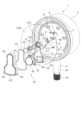
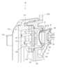
図1は、本実施形態の物理量測定装置1の概略を示す斜視図であり、図2は、物理量測定装置1の概略を示す分解斜視図であり、図3は、物理量測定装置1の概略を示す断面斜視図である。
図1~図3に示すように、物理量測定装置1は、導入部材2と、物理量測定装置本体部3と、ブルドン管4と、指針5と、指針伝達機構6と、目盛板7と、支持部材8と、磁石9と、指針読取装置10とを備える。このように、本実施形態の物理量測定装置1はブルドン管式の圧力計として構成されている。 [First embodiment]
A physical
FIG. 1 is a perspective view showing an outline of a physical
1 to 3, the physical
[導入部材2]
導入部材2は、図示しない配管等の被取付部に取り付けられる所謂継手部材であり、黄銅・ステンレス鋼・鉄鋼等の金属部材で形成されている。そして、導入部材2は、導入部材本体部21と、当該導入部材本体部21の先端部に設けられた雄ねじ部22とを備える。導入部材本体部21の内部には、被取付部から被測定流体を導入する流体導入孔211が形成されており、当該流体導入孔211はブルドン管4に接続されている。また、雄ねじ部22は被取付部に螺合される。 [Introduction member 2]
The
[物理量測定装置本体部3]
物理量測定装置本体部3は、金属製で有底円筒状に形成されており、内部にブルドン管4、指針5、指針伝達機構6、目盛板7、支持部材8、および、磁石9を収納している。そして、物理量測定装置本体部3の開口部は、後述する指針読取装置10のケース底部112の円盤部1122に覆われている。なお、物理量測定装置本体部3は、上記構成に限られるものではなく、例えば、樹脂製であってもよい。 [Physical quantity measuring device main unit 3]
The physical quantity measuring device
[ブルドン管4]
ブルドン管4は、金属製であり、内部に導入された被測定流体の圧力に応じて先端部が変位する。本実施形態の物理量測定装置1は、当該ブルドン管4の変位量を、指針伝達機構6を介して指針5に伝達することで、被測定流体の圧力を測定可能に構成されている。
また、本実施形態では、前述したようにブルドン管4は、導入部材2と接続されており、流体導入孔211と連通している。 [Bourdon tube 4]
The Bourdon tube 4 is made of metal, and its tip is displaced in response to the pressure of the fluid to be measured introduced therein. The physical
In this embodiment, as described above, the Bourdon tube 4 is connected to the
[指針5]
指針5は、ブルドン管4にて検出した被測定流体の圧力を指示する部材であり、指針本体51と、回動軸52とを有する。
指針本体51は、回動軸52を回転軸として回動することにより、ブルドン管4にて検出した被測定流体の圧力に応じて目盛板7に表示された目盛71(後述)を指示する。
回動軸52は、目盛板7の中心部に形成された軸部挿通孔72を貫通するとともに、指針伝達機構6に連結している。これにより、被測定流体の圧力によるブルドン管4の先端部の変位量を、指針伝達機構6を介して、指針本体51に伝達可能に構成されている。 [Guideline 5]
The
The
The rotating
[指針伝達機構6]
指針伝達機構6は、所謂内機を備えて構成され、ブルドン管4の先端部の変位量を拡大して指針5に伝達するように構成されている。 [Needle transmission mechanism 6]
The
[目盛板7]
目盛板7は、後述する指針読取装置10のケース底部112の円盤部1122に対向するように配置されており、表面に目盛71が表記されている。本実施形態では、目盛71は、目盛板7の表面に円弧状に表記されている。
これにより、物理量測定装置1は、当該目盛71を指針本体51に指示させることにより、被測定流体の圧力を表示可能に構成されている。また、目盛板7には、表面から裏面へと貫通する軸部挿通孔72が形成されている。 [Scale plate 7]
The
Thus, the physical
[支持部材8]
図4は、指針読取装置10の要部の概略を示す断面斜視図である。
図1~図4に示すように、支持部材8は、磁石9を指針5の回動軸52の先端に取り付けるための部材である。本実施形態では、支持部材8は、支持部材本体部81と、収納凹部82と、取付部83とを有する。 [Support member 8]
FIG. 4 is a cross-sectional perspective view showing an outline of the main parts of the
1 to 4, the
支持部材本体部81は、樹脂製で柱状とされている。そして、支持部材本体部81の一方の端部には、磁石9が嵌合されて収納される収納凹部82が設けられている。
また、支持部材本体部81の他方の端部には、指針本体51に係合可能とされた爪状の取付部83が設けられている。これにより、本実施形態では、支持部材本体部81が指針5に取り付けることができるように構成されている。このように、本実施形態では、磁石9を収納する収納凹部82を備えた支持部材8に、指針5に係合可能な取付部83が設けられるので、指針5に対して磁石9を容易に取り付けることができる。
さらに、本実施形態では、支持部材本体部81の他方の端部と回動軸52の先端とが、両面テープ等により構成される接着部材84により接着されている。
なお、支持部材8は、上記構成に限られるものではなく、例えば、接着部材が設けられず取付部のみにより指針に取り付けられていてもよく、あるいは、取付部が設けられず接着部材のみにより指針に取り付けられていてもよい。さらに、磁石が収納凹部に嵌合されることに限られるものではなく、例えば、支持部材の端部に磁石が接着部材により接着されていてもよい。 The support member
Furthermore, a claw-shaped
Furthermore, in this embodiment, the other end of the support member
The
[指針読取装置10]
指針読取装置10は、被測定流体の圧力に応じて回動軸52を中心に回動する指針本体51の回動角を読み取る装置である。本実施形態では、指針読取装置10は、ケース部材11と、ガイド部材12と、測定回路基板13と、磁気センサ14と、通信基板15と、電池16と、第1パッキン171と、第2パッキン172と、第3パッキン173とを有する。なお、電池16は本発明の電源部の一例である。 [Needle reading device 10]
The
[ケース部材11]
ケース部材11は、ガイド部材12、測定回路基板13、磁気センサ14、通信基板15、および、電池16等を収納するケースである。本実施形態では、ケース部材11は、ケース本体部111と、ケース底部112と、ケース蓋部113とを有する。そして、本実施形態では、ケース部材11は、目盛板7の目盛71が表示されていない位置に配置されるように、指針読取装置10が物理量測定装置1に取り付けられている。これにより、指針読取装置10が物理量測定装置本体部3に取り付けられた際に、指針5による目盛71の指示が見えにくくなってしまうことを抑制することができる。 [Case member 11]
The
ケース本体部111は、樹脂製で筒状とされ、第1ケース部1111と、第2ケース部1112とを備える。
第1ケース部1111は、回動軸52の軸方向から視て、一部が回動軸52と重なる位置、すなわち、目盛板7の中心部付近に配置されている。そして、第1ケース部1111は、内部にガイド部材12、測定回路基板13、および、磁気センサ14等を収容している。 The case
The
第2ケース部1112は、第1ケース部1111よりも大きくなるように形成され、目盛板7の下部付近に配置されている。すなわち、第2ケース部1112は、円弧状に目盛71が表記された目盛板7において、目盛71と重ならない位置に配置されている。そして、第2ケース部1112は、内部に通信基板15、および、電池16等を収納している。これにより、円弧状の目盛71が表記されない目盛板7の位置に第2ケース部1112を配置することで、ケース部材11によって目盛71が読み取りにくくなってしまうことを抑制でき、かつ、通信基板15および電池16を収容するためのスペースを確保することができる。The
また、本実施形態では、ケース本体部111の四隅近傍に爪部114が形成されている。そして、当該爪部114が後述するケース蓋部113の係合溝部115と係合することにより、ケース蓋部113がケース本体部111に着脱可能に取り付けられるように構成されている。In addition, in this embodiment,
ケース底部112は、ケース本体部111の一方の端部側を覆うように構成されている。本実施形態では、ケース底部112は、ケース底部本体部1121と、円盤部1122とを有する。
ケース底部本体部1121は、樹脂製でケース本体部111の一方の端部を覆うように構成されている。そして、ケース底部本体部1121には、支持部材8に対向する位置に、孔部116が形成されている。さらに、ケース底部本体部1121には、孔部116の周縁近傍から支持部材8に向かって延出する係合爪部117が複数設けられている。なお、係合爪部117の詳細については、後述する。
円盤部1122は、透明樹脂により円盤状に形成され、物理量測定装置本体部3の開口部を覆うように配置されており、物理量測定装置本体部3に対して着脱可能に取り付けられている。これにより、ケース底部112は、物理量測定装置本体部3に対して着脱可能とされている。さらに、円盤部1122は透明樹脂により形成されるので、円盤部1122を通して指針5や目盛板7を視認することができるように構成されている。 The
The case bottom
The
ケース蓋部113は、ケース本体部111の他方の端部を覆うように配置され、前述したようにケース本体部111に着脱可能に形成されている。具体的には、ケース蓋部113における四隅近傍に係合溝部115が形成され、当該係合溝部115にケース本体部111の爪部114が係合できるように構成されている。また、本実施形態では、ケース蓋部113とケース本体部111との間には、環状とされた第1パッキン171が介装されて、ケース蓋部113とケース本体部111との間が封止されている。
このように、本実施形態では、ケース蓋部113はケース本体部111に着脱可能に取り付けられるので、ケース本体部111に収納される測定回路基板13や磁気センサ14等をメンテナンスしたり、電池16を交換したりすることを容易にすることができる。
さらに、本実施形態では、ケース蓋部113におけるケース本体部111を覆う内面側には、ガイド部材12に対応する位置に、ガイド部材12に向かって突出する突状部118が形成されている。 The
In this manner, in this embodiment, the
Furthermore, in this embodiment, a
[ガイド部材12]
ガイド部材12は、磁気センサ14が取り付けられる測定回路基板13を所定の位置に位置決めするための部材である。本実施形態では、ガイド部材12は、基板支持部121と、筒部122とを有する。 [Guide member 12]
The
基板支持部121は、樹脂製で有底円筒状に形成され、内部に測定回路基板13を収納して保持するように構成されている。筒部122は、円筒状とされ、基板支持部121からケース底部112の孔部116に向かって延出している。そして、筒部122は、ケース底部112の孔部116に収納されるように構成されている。この際、筒部122は、ケース底部112に設けられた係合爪部117を付勢するように構成されている。
さらに、前述したように、ケース蓋部113にはガイド部材12に対応する位置に突状部118が形成されているので、ケース蓋部113がケース本体部111に取り付けられた際に、ガイド部材12は突状部118により支持部材8に向かって付勢される。そのため、ケース蓋部113をケース本体部111に取り付けた状態で、支持部材8に対するガイド部材12の位置がずれてしまうことを抑制することができる。
なお、本実施形態では、突状部118と基板支持部121との間には第2パッキン172が介装され、かつ、基板支持部121とケース底部112との間には第3パッキン173が介装されている。 The
Furthermore, as described above,
In this embodiment, a
[測定回路基板13]
測定回路基板13は、図示略の電子部品等が配置されており、通信基板15と電気的に接続されている。そして、本実施形態では、測定回路基板13には磁気センサ14が取り付けられている。これにより、測定回路基板13は、磁気センサ14から出力される信号を入力して、指針5の回動角に応じた信号を通信基板15に出力可能に構成されている。 [Measurement circuit board 13]
The
[磁気センサ14]
磁気センサ14は、磁気検出素子を備えて構成され、支持部材8に固定される磁石9の磁場を検出可能に構成されている。本実施形態では、磁気センサ14は、測定回路基板13の磁石9に対向する側の面に取り付けられている。
これにより、指針5が回動すると、支持部材8を介して回動軸52の先端に取り付けられた磁石9が回動し、この回動角を磁気センサ14にて検出できるように構成されている。そして、前述したように、指針5の回動角に応じて磁気センサ14が検出した信号は、測定回路基板13を介して通信基板15に出力される。 [Magnetic sensor 14]
The
As a result, when the
[通信基板15]
通信基板15は、アンテナ等を備えて構成され、外部装置と信号を送受信可能に構成されている。本実施形態では、通信基板15は、Bluetooth(登録商標)の電波を送受信可能に構成されている。これにより、通信基板15は、磁気センサ14が出力した信号を外部装置に出力することができる。なお、通信基板15は、上記構成に限られるものではなく、例えば、LPWA(Low Power Wide Area)、Wi-Fi(登録商標)、NFC等の電波や赤外線等を送受信可能に構成されていてもよい。これにより、本実施形態では、指針5の回動角に応じた信号を外部装置に無線で出力することができるので、有線のケーブルを用いることなく指針5の回動角に応じた信号を外部装置に出力することができ、信号を出力するためのケーブルによって目盛板7に表記された目盛71が読み取りにくくなってしまうことを抑制することができる。 [Communication board 15]
The
[電池16]
電池16は、前述したように、通信基板15に設けられた電池ケース151に1個収納されており、測定回路基板13、磁気センサ14、通信基板15等に電力を供給可能に構成されている。本実施形態では、電池16は、コイン型電池を含む所謂ボタン型電池として構成されている。なお、電池16は、上記構成に限られるものではなく、例えば、円筒型乾電池、円筒型充電池、ポリマー電池等として構成されていてもよい。さらに、指針読取装置10に電池16が複数内蔵されていてもよい。 [Battery 16]
As described above, one
以上のような本実施形態では、次の効果を奏することができる。
(1)本実施形態では、指針5の回動角に応じた信号を出力する測定回路基板13と、測定回路基板13から出力された信号を外部装置に無線で出力する通信基板15と、を備えるので、有線のケーブルを用いることなく指針5の回動角に応じた信号を外部装置に出力することができる。そのため、信号を出力するためのケーブルによって目盛板7に表記された目盛71が読み取りにくくなってしまうことを抑制することができる。
また、本実施形態では、磁気センサ14、通信基板15および電池16を収容するケース部材11は、指針5の回動軸52の軸方向から視て、目盛板7に円弧状に表記され指針5によって指示される目盛71と重ならない位置に配置されるので、ケース部材11によって目盛71が読み取りにくくなってしまうことを抑制することができる。
さらに、本実施形態では、磁気センサ14をケース部材11の第1ケース部1111に収容し、通信基板15および電池16を第1ケース部1111よりも大きい第2ケース部1112に収容するので、円弧状の目盛71が表記されない目盛板7の下部に第2ケース部1112を配置することで、ケース部材11によって目盛71が読み取りにくくなってしまうことを抑制でき、かつ、通信基板15および電池16を収容するためのスペースを確保することができる。
ここで、磁気センサや通信基板等を収納するケースを円筒形に形成し、回動軸が配置される中央部のみに配置してしまった場合、磁気センサや通信基板を収納するスペースを確保するために当該ケースの径が大きくなったり、ケースの厚さが大きくなったりしてしまうおそれがある。そうすると、目盛とケースとの距離が近くなることから、物理量測定装置を斜めの方向から視た場合に、目盛にケースが重なってしまい、目盛が読み取りにくくなってしまうおそれがある。
これに対し、本実施形態では、磁気センサ14や通信基板15を収納するケース部材11が第1ケース部1111および第2ケース部1112を備えるので、ケース部材11を中央部のみに配置する必要がなく、目盛71が配置されていない目盛板7の箇所に対応する位置に第2ケース部1112を配置することで、スペースを有効に活用することができる。そのため、目盛71とケース部材11との距離が近くなることを抑制でき、物理量測定装置1を斜めの方向から視た場合においても、目盛71が読み取りにくくなってしまうことを抑制できる。 The present embodiment as described above can provide the following effects.
(1) In this embodiment, the measuring
Furthermore, in this embodiment, the
Furthermore, in this embodiment, the
Here, if the case for housing the magnetic sensor, communication board, etc. is formed into a cylindrical shape and placed only in the center where the rotation shaft is located, the diameter of the case may become large or the thickness of the case may become large in order to secure space for housing the magnetic sensor and communication board. In that case, the distance between the scale and the case becomes short, and therefore when the physical quantity measuring device is viewed from an oblique direction, the case may overlap the scale, making it difficult to read the scale.
In contrast, in this embodiment, the
(2)本実施形態では、指針5に取り付けられた磁石9の磁場を磁気センサ14により検出することで、被測定流体の圧力に対応する指針5の回動角に応じた信号を出力することができる。(2) In this embodiment, the magnetic field of the
[第2実施形態]
次に、本発明の第2実施形態について図面に基づいて説明する。
第2実施形態では、ケース本体部111Aに対してケース蓋部113Aが回動することで開閉するように構成されている点で第1実施形態と異なる。なお、第2実施形態において、第1実施形態と同一または同様の構成には同一符号を付し、説明を省略する。 [Second embodiment]
Next, a second embodiment of the present invention will be described with reference to the drawings.
The second embodiment differs from the first embodiment in that the
図5は、第2実施形態に係る物理量測定装置1Aの概略を示す斜視図であり、図6は、物理量測定装置1Aにおいてケース蓋部113Aを開けた状態を示す斜視図である。なお、図6では、ケース部材11Aに収納されるガイド部材12、測定回路基板13、磁気センサ14、通信基板15、および、電池16等の記載を省略して示している。
図5、図6に示すように、第2実施形態の物理量測定装置1Aは、前述した第1実施形態の物理量測定装置1と同様に、導入部材2と、物理量測定装置本体部3と、指針5と、目盛板7と、指針読取装置10Aとを備える。
そして、本実施形態の指針読取装置10Aは、前述した第1実施形態の指針読取装置10と同様に、ケース部材11Aを備える。 Fig. 5 is a perspective view showing an outline of the physical
As shown in Figures 5 and 6, the physical
The
[ケース部材11A]
ケース部材11Aは、前述した第1実施形態のケース部材11と同様に、ケース本体部111Aと、ケース蓋部113Aとを有する。さらに、本実施形態のケース部材11Aは、回転軸部119Aを有する。
ケース本体部111Aは、樹脂製で筒状とされ、第1ケース部1111Aと、第2ケース部1112Aとを備える。 [
The
The case
また、本実施形態では、ケース本体部111Aの上部2箇所に爪部114Aが形成されている。そして、当該爪部114Aが後述するケース蓋部113Aの係合孔部115Aと係合するように構成されている。In this embodiment,
さらに、本実施形態では、ケース本体部111Aの下部に回転軸部119Aが設けられている。そして、ケース蓋部113Aは、当該回転軸部119Aを回転軸として、ケース本体部111Aに対して回動可能に支持されている。これにより、ケース蓋部113Aは、ケース本体部111Aに対して開閉可能に構成されている。Furthermore, in this embodiment, a
ここで、本実施形態では、回動軸52(図3参照)の軸方向から視て、すなわち、目盛板7の正面側から視て、第2ケース部1112Aは、少なくとも一部が目盛板7と重ならない位置に配置されている。これにより、通信基板15および電池16(図2参照)を収容する第2ケース部1112Aの少なくとも一部が目盛板7と重ならない位置に配置される、すなわち、第2ケース部1112Aの一部が目盛板7からはみ出した位置に配置されるので、目盛板7が小径化したとしても通信基板15および電池16を収容するためのスペースを確保することができる。In this embodiment, when viewed from the axial direction of the pivot shaft 52 (see FIG. 3), i.e., when viewed from the front side of the
以上のような本実施形態では、次の効果を奏することができる。
(3)本実施形態では、通信基板15および電池16を収容する第2ケース部1112Aの少なくとも一部が目盛板7と重ならない位置に配置される、すなわち、第2ケース部1112Aの一部が目盛板7からはみ出した位置に配置されるので、目盛板7が小径化したとしても通信基板15および電池16を収容するためのスペースを確保することができる。 The present embodiment as described above can provide the following effects.
(3) In the present embodiment, at least a portion of the
[変形例]
なお、本発明は前述の各実施形態に限定されるものではなく、本発明の目的を達成できる範囲での変形、改良等は本発明に含まれるものである。 [Modification]
The present invention is not limited to the above-described embodiments, and modifications and improvements within the scope of the present invention that can achieve the object of the present invention are included in the present invention.
前記各実施形態では、ケース部材11,11Aは、透明樹脂を用いて形成された円盤部1122を有して構成されていたが、これに限定されない。例えば、ケース部材は、物理量測定装置本体部の開口部を覆う透明カバー部材に対して、接着部材等により取り付けられるように構成されていてもよい。この場合、ケース部材のケース底部に孔部が設けられるとともに、透明カバー部材にも当該孔部に対応する位置に孔部が設けられる。In each of the above embodiments, the
前記第2実施形態では、ケース本体部111Aの上部に爪部114Aを設け、ケース本体部111Aの下部に回転軸部119Aを設けていたが、これに限定されない。例えば、ケース本体部の下部に爪部を設け、ケース本体部の上部に回転軸部を設けていてもよい。さらに、ケース本体部の一方の側面側に爪部を設け、他方の側面側に回転軸部を設ける、すなわち、ケース蓋部が横開きになるように構成されていてもよい。In the second embodiment, the
前記各実施形態では、物理量測定装置1,1Aは、被測定流体の圧力を測定可能に構成されていたが、これに限定されない。例えば、物理量測定装置は、温度や差圧等の物理量を測定可能に構成されていてもよい。In each of the above embodiments, the physical
1,1A…物理量測定装置、2…導入部材、3…物理量測定装置本体部、4…ブルドン管、5…指針、6…指針伝達機構、7…目盛板、8…支持部材、9…磁石、10,10A…指針読取装置、11,11A…ケース部材、12…ガイド部材、13…測定回路基板、14…磁気センサ、15…通信基板、16…電池、21…導入部材本体部、22…雄ねじ部、51…指針本体、52…回動軸、71…目盛、72…軸部挿通孔、81…支持部材本体部、82…収納凹部、83…取付部、84…接着部材、111,111A…ケース本体部、112…ケース底部、113,113A…ケース蓋部、114,114A…爪部、115…係合溝部、115A…係合孔部、116…孔部、117…係合爪部、118…突状部、119A…回転軸部、121…基板支持部、122…筒部、151…電池ケース、171…第1パッキン、172…第2パッキン、173…第3パッキン、211…流体導入孔、1121…ケース底部本体部、1122…円盤部。1, 1A...Physical quantity measuring device, 2...Introduction member, 3...Physical quantity measuring device main body, 4...Bourdon tube, 5...Pointer, 6...Pointer transmission mechanism, 7...Scale plate, 8...Support member, 9...Magnet, 10, 10A...Pointer reading device, 11, 11A...Case member, 12...Guide member, 13...Measurement circuit board, 14...Magnetic sensor, 15...Communication board, 16...Battery, 21...Introduction member main body, 22...Male threaded portion, 51...Pointer body, 52...Pivot shaft, 71...Scale, 72...Shaft insertion hole, 81...Support member main body, 82...Storage recess, 83 ...mounting portion, 84...adhesive member, 111, 111A...case body, 112...case bottom, 113, 113A...case lid, 114, 114A...claw portion, 115...engagement groove, 115A...engagement hole, 116...hole, 117...engagement claw, 118...projection, 119A...rotating shaft, 121...substrate support, 122...tubular portion, 151...battery case, 171...first packing, 172...second packing, 173...third packing, 211...fluid introduction hole, 1121...case bottom body, 1122...disk.
Claims (3)
Translated fromJapanese前記回動軸の先端に取り付けられる支持部材に固定される磁石の磁場を検出する磁気センサと、
前記磁気センサが取り付けられ、前記磁気センサから出力される信号を入力し、前記指針の回動角に応じた信号を出力する測定回路基板と、
前記測定回路基板から出力された信号を外部装置に無線で出力する通信基板と、
前記測定回路基板および前記通信基板に電力を供給する電源部と、
前記回動軸の軸方向から視て、目盛板に円弧状に表記され前記指針によって指示される目盛と重ならない位置に配置されるケース部材と、を備え、
前記ケース部材は、前記磁気センサを収容する第1ケース部と、前記通信基板および前記電源部を収容し、かつ、前記第1ケース部よりも大きい第2ケース部と、を有する
ことを特徴とする指針読取装置。 A pointer reading device that reads a rotation angle of a pointer that rotates around a rotation axis in response to a physical quantity of a fluid to be measured,
a magnetic sensor that detects a magnetic field of a magnet fixed to a support member attached to a tip of the rotating shaft;
a measurement circuit board to which the magnetic sensor is attached, to which a signal output from the magnetic sensor is input, and to which a signal corresponding to a rotation angle of the pointer is output;
a communication board that wirelessly outputs a signal output from the measurement circuit board to an external device;
a power supply unit for supplying power to the measurement circuit board and the communication board;
a case member that is arranged at a position not overlapping with a scale indicated by the pointer and marked in an arc shape on the scale plate when viewed from the axial direction of the rotation shaft,
the case member has a first case portion that houses the magnetic sensor, and a second case portion that houses the communication board and the power supply portion and is larger than the first case portion.
前記回動軸の軸方向から視て、前記第2ケース部は、少なくとも一部が前記目盛板と重ならない位置に配置される
ことを特徴とする指針読取装置。 The pointer reading device according to claim 1,
a second case portion disposed at a position where at least a portion of the second case portion does not overlap with the scale plate when viewed from an axial direction of the rotation shaft.
被測定流体の物理量に応じて前記回動軸を中心に回動する前記指針と、
前記磁石と、
前記目盛が表記される前記目盛板と、を備える
ことを特徴とする物理量測定装置。 A pointer reading device according to claim 1 ;
the pointer that rotates around the rotation axis in response to a physical quantity of the fluid to be measured;
The magnet;
and a scale plate on which the scale is marked.
Priority Applications (1)
| Application Number | Priority Date | Filing Date | Title |
|---|---|---|---|
| JP2023088595AJP2024171537A (en) | 2023-05-30 | 2023-05-30 | Pointer reading device and physical quantity measuring device |
Applications Claiming Priority (1)
| Application Number | Priority Date | Filing Date | Title |
|---|---|---|---|
| JP2023088595AJP2024171537A (en) | 2023-05-30 | 2023-05-30 | Pointer reading device and physical quantity measuring device |
Publications (1)
| Publication Number | Publication Date |
|---|---|
| JP2024171537Atrue JP2024171537A (en) | 2024-12-12 |
Family
ID=93799306
Family Applications (1)
| Application Number | Title | Priority Date | Filing Date |
|---|---|---|---|
| JP2023088595APendingJP2024171537A (en) | 2023-05-30 | 2023-05-30 | Pointer reading device and physical quantity measuring device |
Country Status (1)
| Country | Link |
|---|---|
| JP (1) | JP2024171537A (en) |
- 2023
- 2023-05-30JPJP2023088595Apatent/JP2024171537A/enactivePending
Similar Documents
| Publication | Publication Date | Title |
|---|---|---|
| JP3161399U (en) | Pointer reader | |
| EP3101401B1 (en) | Pressure gauge | |
| WO2016022756A1 (en) | Removable magnetostrictive probe with automatic calibration | |
| US5363690A (en) | Gas detection apparatus | |
| BR102018069869B1 (en) | LIQUID GAS LEVEL MEASUREMENT SYSTEM | |
| WO2019044280A1 (en) | Output system and meter | |
| CN107764149B (en) | External device for measuring instrument | |
| US20090212767A1 (en) | Remote transmitter for analogue gauges | |
| EP3816601B1 (en) | Pressure gauge | |
| CA2957227C (en) | Rotatable and removable multi-pin explosion proof connector assembly | |
| JP2024171537A (en) | Pointer reading device and physical quantity measuring device | |
| WO2024219269A1 (en) | Sensor device system | |
| JP7695220B2 (en) | Pointer reading device, physical quantity measuring device, and method for installing a pointer reading device | |
| US10175134B2 (en) | Physical quantity measuring device | |
| CN109196313B (en) | Flow meter, flow meter cartridge and related methods | |
| US10775144B2 (en) | Length measuring device | |
| KR200437414Y1 (en) | Level gauge for flammable liquefied gas storage tank | |
| US20140375471A1 (en) | Field Device | |
| CN213091059U (en) | Compact explosion-proof pressure transmitter | |
| JP7689402B1 (en) | Pressure | |
| JP6154623B2 (en) | Pressure gauge | |
| KR100729643B1 (en) | Zero Correction Device of Electronic Flowmeter | |
| CN217083844U (en) | Ultrasonic flowmeter | |
| US20250264364A1 (en) | Liquid temperature sensor apparatus | |
| CN111487007B (en) | Pressure transmitter with adjustable pressure sensor |