JP2024163600A - Electrode body and storage cell - Google Patents
Electrode body and storage cellDownload PDFInfo
- Publication number
- JP2024163600A JP2024163600AJP2023079356AJP2023079356AJP2024163600AJP 2024163600 AJP2024163600 AJP 2024163600AJP 2023079356 AJP2023079356 AJP 2023079356AJP 2023079356 AJP2023079356 AJP 2023079356AJP 2024163600 AJP2024163600 AJP 2024163600A
- Authority
- JP
- Japan
- Prior art keywords
- separator
- electrode
- electrodes
- folded portion
- outermost
- Prior art date
- Legal status (The legal status is an assumption and is not a legal conclusion. Google has not performed a legal analysis and makes no representation as to the accuracy of the status listed.)
- Pending
Links
Images


Classifications
- H—ELECTRICITY
- H01—ELECTRIC ELEMENTS
- H01M—PROCESSES OR MEANS, e.g. BATTERIES, FOR THE DIRECT CONVERSION OF CHEMICAL ENERGY INTO ELECTRICAL ENERGY
- H01M50/00—Constructional details or processes of manufacture of the non-active parts of electrochemical cells other than fuel cells, e.g. hybrid cells
- H01M50/40—Separators; Membranes; Diaphragms; Spacing elements inside cells
- H01M50/463—Separators, membranes or diaphragms characterised by their shape
- H01M50/466—U-shaped, bag-shaped or folded
- H—ELECTRICITY
- H01—ELECTRIC ELEMENTS
- H01M—PROCESSES OR MEANS, e.g. BATTERIES, FOR THE DIRECT CONVERSION OF CHEMICAL ENERGY INTO ELECTRICAL ENERGY
- H01M10/00—Secondary cells; Manufacture thereof
- H01M10/04—Construction or manufacture in general
- H01M10/0459—Cells or batteries with folded separator between plate-like electrodes
- H—ELECTRICITY
- H01—ELECTRIC ELEMENTS
- H01M—PROCESSES OR MEANS, e.g. BATTERIES, FOR THE DIRECT CONVERSION OF CHEMICAL ENERGY INTO ELECTRICAL ENERGY
- H01M10/00—Secondary cells; Manufacture thereof
- H01M10/05—Accumulators with non-aqueous electrolyte
- H01M10/058—Construction or manufacture
- H01M10/0583—Construction or manufacture of accumulators with folded construction elements except wound ones, i.e. folded positive or negative electrodes or separators, e.g. with "Z"-shaped electrodes or separators
- H—ELECTRICITY
- H01—ELECTRIC ELEMENTS
- H01M—PROCESSES OR MEANS, e.g. BATTERIES, FOR THE DIRECT CONVERSION OF CHEMICAL ENERGY INTO ELECTRICAL ENERGY
- H01M10/00—Secondary cells; Manufacture thereof
- H01M10/42—Methods or arrangements for servicing or maintenance of secondary cells or secondary half-cells
- H01M10/4235—Safety or regulating additives or arrangements in electrodes, separators or electrolyte
- H—ELECTRICITY
- H01—ELECTRIC ELEMENTS
- H01M—PROCESSES OR MEANS, e.g. BATTERIES, FOR THE DIRECT CONVERSION OF CHEMICAL ENERGY INTO ELECTRICAL ENERGY
- H01M50/00—Constructional details or processes of manufacture of the non-active parts of electrochemical cells other than fuel cells, e.g. hybrid cells
- H01M50/10—Primary casings; Jackets or wrappings
- H01M50/102—Primary casings; Jackets or wrappings characterised by their shape or physical structure
- H01M50/103—Primary casings; Jackets or wrappings characterised by their shape or physical structure prismatic or rectangular
- H—ELECTRICITY
- H01—ELECTRIC ELEMENTS
- H01M—PROCESSES OR MEANS, e.g. BATTERIES, FOR THE DIRECT CONVERSION OF CHEMICAL ENERGY INTO ELECTRICAL ENERGY
- H01M50/00—Constructional details or processes of manufacture of the non-active parts of electrochemical cells other than fuel cells, e.g. hybrid cells
- H01M50/10—Primary casings; Jackets or wrappings
- H01M50/116—Primary casings; Jackets or wrappings characterised by the material
- H01M50/124—Primary casings; Jackets or wrappings characterised by the material having a layered structure
- H—ELECTRICITY
- H01—ELECTRIC ELEMENTS
- H01M—PROCESSES OR MEANS, e.g. BATTERIES, FOR THE DIRECT CONVERSION OF CHEMICAL ENERGY INTO ELECTRICAL ENERGY
- H01M50/00—Constructional details or processes of manufacture of the non-active parts of electrochemical cells other than fuel cells, e.g. hybrid cells
- H01M50/40—Separators; Membranes; Diaphragms; Spacing elements inside cells
- H01M50/471—Spacing elements inside cells other than separators, membranes or diaphragms; Manufacturing processes thereof
- H01M50/474—Spacing elements inside cells other than separators, membranes or diaphragms; Manufacturing processes thereof characterised by their position inside the cells
- H—ELECTRICITY
- H01—ELECTRIC ELEMENTS
- H01M—PROCESSES OR MEANS, e.g. BATTERIES, FOR THE DIRECT CONVERSION OF CHEMICAL ENERGY INTO ELECTRICAL ENERGY
- H01M50/00—Constructional details or processes of manufacture of the non-active parts of electrochemical cells other than fuel cells, e.g. hybrid cells
- H01M50/40—Separators; Membranes; Diaphragms; Spacing elements inside cells
- H01M50/471—Spacing elements inside cells other than separators, membranes or diaphragms; Manufacturing processes thereof
- H01M50/477—Spacing elements inside cells other than separators, membranes or diaphragms; Manufacturing processes thereof characterised by their shape
- H—ELECTRICITY
- H01—ELECTRIC ELEMENTS
- H01M—PROCESSES OR MEANS, e.g. BATTERIES, FOR THE DIRECT CONVERSION OF CHEMICAL ENERGY INTO ELECTRICAL ENERGY
- H01M50/00—Constructional details or processes of manufacture of the non-active parts of electrochemical cells other than fuel cells, e.g. hybrid cells
- H01M50/60—Arrangements or processes for filling or topping-up with liquids; Arrangements or processes for draining liquids from casings
- H01M50/673—Containers for storing liquids; Delivery conduits therefor
- H01M50/682—Containers for storing liquids; Delivery conduits therefor accommodated in battery or cell casings
- Y—GENERAL TAGGING OF NEW TECHNOLOGICAL DEVELOPMENTS; GENERAL TAGGING OF CROSS-SECTIONAL TECHNOLOGIES SPANNING OVER SEVERAL SECTIONS OF THE IPC; TECHNICAL SUBJECTS COVERED BY FORMER USPC CROSS-REFERENCE ART COLLECTIONS [XRACs] AND DIGESTS
- Y02—TECHNOLOGIES OR APPLICATIONS FOR MITIGATION OR ADAPTATION AGAINST CLIMATE CHANGE
- Y02E—REDUCTION OF GREENHOUSE GAS [GHG] EMISSIONS, RELATED TO ENERGY GENERATION, TRANSMISSION OR DISTRIBUTION
- Y02E60/00—Enabling technologies; Technologies with a potential or indirect contribution to GHG emissions mitigation
- Y02E60/10—Energy storage using batteries
- Y—GENERAL TAGGING OF NEW TECHNOLOGICAL DEVELOPMENTS; GENERAL TAGGING OF CROSS-SECTIONAL TECHNOLOGIES SPANNING OVER SEVERAL SECTIONS OF THE IPC; TECHNICAL SUBJECTS COVERED BY FORMER USPC CROSS-REFERENCE ART COLLECTIONS [XRACs] AND DIGESTS
- Y02—TECHNOLOGIES OR APPLICATIONS FOR MITIGATION OR ADAPTATION AGAINST CLIMATE CHANGE
- Y02P—CLIMATE CHANGE MITIGATION TECHNOLOGIES IN THE PRODUCTION OR PROCESSING OF GOODS
- Y02P70/00—Climate change mitigation technologies in the production process for final industrial or consumer products
- Y02P70/50—Manufacturing or production processes characterised by the final manufactured product
Landscapes
- Chemical & Material Sciences (AREA)
- Chemical Kinetics & Catalysis (AREA)
- Electrochemistry (AREA)
- General Chemical & Material Sciences (AREA)
- Engineering & Computer Science (AREA)
- Manufacturing & Machinery (AREA)
- Secondary Cells (AREA)
- Cell Separators (AREA)
Abstract
Description
Translated fromJapanese本開示は、電極体及び蓄電セルに関する。This disclosure relates to an electrode assembly and a storage cell.
特開2021-48141号公報には、交互に配置される複数の正極及び複数の負極と、セパレータと、を備える積層電極群が開示されている。セパレータは、正極及び負極の間に配置されたつづら折り形状のつづら折り部と、つづら折り部に連続する覆い部と、を有している。覆い部は、積層電極群の周囲を覆うように配置されている。覆い部の先端部は、覆い部の根元部に絶縁テープまたは熱溶着で接続されている。JP 2021-48141 A discloses a stacked electrode group including a plurality of positive electrodes and a plurality of negative electrodes arranged alternately, and a separator. The separator has a zigzag-shaped zigzag portion arranged between the positive electrodes and the negative electrodes, and a cover portion continuous with the zigzag portion. The cover portion is arranged so as to cover the periphery of the stacked electrode group. The tip portion of the cover portion is connected to the base portion of the cover portion by insulating tape or heat welding.
特開2021-48141号公報に記載される積層電極群では、積層電極群の搬送時や積層電極群のセルケースへの挿入時、あるいは、積層電極群を含む蓄電セルの振動時などに、電極同士の位置ずれが生じる懸念がある。In the stacked electrode group described in JP 2021-48141 A, there is a concern that the electrodes may become misaligned when the stacked electrode group is transported, when the stacked electrode group is inserted into a cell case, or when the power storage cell including the stacked electrode group is vibrated.
本開示の目的は、電極同士の位置ずれを抑制することが可能な電極体及び蓄電セルを提供することである。The objective of this disclosure is to provide an electrode assembly and a storage cell that can suppress misalignment of the electrodes.
本開示の一局面に従った電極体は、一方向に並ぶように配置された複数の電極と、つづら折り状に形成されており、前記複数の電極の各々の間を絶縁するセパレータと、を備え、前記セパレータは、前記一方向に互いに隣接する一対の電極間に介在する複数の介在部と、前記複数の介在部のうちの一の介在部の上端部と、前記複数の介在部のうち前記一方向における一方側に前記一の介在部に隣接する介在部の上端部と、を互いに連結する上折返し部と、前記複数の介在部のうちの前記一の介在部の下端部と、前記複数の介在部のうち前記一方向における他方側に前記一の介在部に隣接する介在部の下端部と、を互いに連結する下折返し部と、前記上折返し部及び前記下折返し部をまとめて被覆する最外被覆部と、を含み、前記上折返し部は、前記最外被覆部に接続されており、前記下折返し部は、前記最外被覆部に接続されている。An electrode body according to one aspect of the present disclosure includes a plurality of electrodes arranged in one direction, and a separator formed in a zigzag shape that insulates between each of the plurality of electrodes, the separator including a plurality of intervening parts interposed between a pair of electrodes adjacent to each other in the one direction, an upper folded part connecting an upper end of one of the plurality of intervening parts and an upper end of one of the plurality of intervening parts adjacent to the one intervening part on one side in the one direction, a lower folded part connecting a lower end of one of the plurality of intervening parts and a lower end of one of the plurality of intervening parts adjacent to the one intervening part on the other side in the one direction, and an outermost covering part that covers the upper folded part and the lower folded part together, the upper folded part being connected to the outermost covering part, and the lower folded part being connected to the outermost covering part.
本開示の一局面に従った蓄電セルは、前記電極体と、前記電極体を収容するセルケースと、を備える。A storage cell according to one aspect of the present disclosure comprises the electrode assembly and a cell case that houses the electrode assembly.
本開示によれば、電極同士の位置ずれを抑制することが可能な電極体及び蓄電セルを提供することができる。The present disclosure provides an electrode assembly and a storage cell that can suppress misalignment between electrodes.
本開示の実施形態について、図面を参照して説明する。なお、以下で参照する図面では、同一またはそれに相当する部材には、同じ番号が付されている。Embodiments of the present disclosure will be described with reference to the drawings. Note that in the drawings referred to below, identical or equivalent components are given the same numbers.
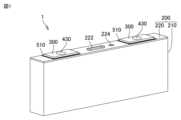
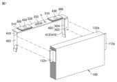
図1は、本開示の一実施形態における蓄電セルを概略的に示す斜視図である。図2は、図1に示される蓄電セルの断面図である。Figure 1 is a perspective view showing a schematic diagram of a storage cell according to one embodiment of the present disclosure. Figure 2 is a cross-sectional view of the storage cell shown in Figure 1.
図1及び図2に示されるように、蓄電セル1は、電極体100と、セルケース200と、電解液(図示略)と、一対の外部端子300と、一対の連結部材400と、絶縁部材500と、を備えている。As shown in Figures 1 and 2, the storage cell 1 includes an
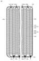
図3は、電極体の断面図である。図3に示されるように、電極体100は、複数の電極110,120と、セパレータ130と、絶縁フィルム140(図9を参照)と、を備えている。Figure 3 is a cross-sectional view of the electrode body. As shown in Figure 3, the
図3に示されるように、複数の電極110,120は、一方向(図3における左右方向)に並ぶように配置されている。複数の電極110,120は、複数の正極電極110と、複数の負極電極120と、を有している。As shown in FIG. 3, the
各正極電極110は、幅方向(一方向及び上下方向の双方と直交する方向)に長い長方形形状に形成されている。各正極電極110は、正極集電箔112と、正極集電箔112の両面に設けられた正極活物質層114と、を有している。図2及び図7等に示されるように、正極集電箔112は、正極活物質層114が設けられていない正極タブ112pを有している。正極タブ112pは、幅方向(図3において紙面と直交する方向)における一方側に向かって突出している。Each
各負極電極120は、幅方向に長い長方形形状に形成されている。各負極電極120は、負極集電箔122と、負極集電箔122の両面に設けられた負極活物質層124と、を有している。図2及び図7等に示されるように、負極集電箔122は、負極活物質層124が設けられていない負極タブ122nを有している。負極タブ122nは、幅方向における他方側に向かって突出している。Each
セパレータ130は、正極電極110及び負極電極120間を絶縁している。セパレータ130は、絶縁材料からなり、イオンの透過を許容する微小な空隙を有している。図3に示されるように、セパレータ130は、つづら折り状に形成されている。The
図4は、つづら折り状に形成される前の状態におけるセパレータの平面図である。図4に示されるように、セパレータ130は、つづら折り状に形成される前の状態では長方形形状を呈している。セパレータ130は、各電極110,120間につづら折り状に形成されながら配置される。セパレータ130は、複数の介在部132aと、複数の上折返し部132bと、複数の下折返し部132cと、最外被覆部132dと、を有している。Figure 4 is a plan view of the separator before it is formed into a zigzag shape. As shown in Figure 4, the
各介在部132aは、一方向に互いに隣接する一対の電極110,120間に介在している。つまり、各介在部132aは、正極電極110及び負極電極120間を絶縁する機能を有している。各介在部132aは、矩形状の領域で構成されている。Each intervening
各上折返し部132bは、複数の介在部132aのうちの一の介在部132aの上端部と、複数の介在部132aのうち一方向における一方側に前記一の介在部132aに隣接する介在部132aの上端部と、を互いに連結している。本実施形態では、上折返し部132bは、正極電極110の上方に配置されている。Each upper folded
各下折返し部132cは、複数の介在部132aのうちの前記一の介在部の下端部と、複数の介在部132aのうち一方向における他方側に前記一の介在部に隣接する介在部132aの下端部と、を互いに連結している。本実施形態では、下折返し部132cは、負極電極120の下方に配置されている。換言すれば、負極電極120は、下折返し部132c上に配置されている。Each lower folded
最外被覆部132dは、各上折返し部132b及び各下折返し部132cをまとめて被覆している。より詳細には、最外被覆部132dは、全ての電極110,120、全ての介在部132a、全ての上折返し部132b及び全ての下折返し部132cを、幅方向と平行な中心軸まわりに巻回しながらまとめて被覆している。The
図3に示されるように、最外被覆部132dは、2層で構成された2層部132d1を含んでいる。図3に示される例では、2層部132d1は、下折返し部132cに接触している。As shown in FIG. 3, the
最外被覆部132dは、一方向に正極活物質層114及び負極活物質層124と重ならない位置に設けられた終端132e(図3及び図4を参照)を含んでいる。終端132eは、上折返し部132b又は下折返し部132cと対向する位置に設けられている。本実施形態では、最外被覆部132dの終端132eは、各電極110,120の下方に設けられている。図3に示されるように、終端132eは、負極電極120における負極集電箔122の下端部の下方に設けられている。The
図3に示されるように、最外被覆部132dは、各上折返し部132b及び各下折返し部132cと接続されている。具体的には、最外被覆部132dのうち各上折返し部132bと重なる部位の外側から当該部位に対して、図3において矢印で示されるようにレーザの照射等によって熱が加えられるとともに、最外被覆部132dのうち各下折返し部132cと重なる部位の外側から当該部位に対して、図3において矢印で示されるようにレーザの照射等によって熱が加えられる。これにより、最外被覆部132dが各上折返し部132b及び各下折返し部132cに接続(溶着)される。特に、2層部132d1及び終端132eは、負極電極120の負極集電箔122の下端部と接続(溶着)される。3, the outermost covering
なお、最外被覆部132dは、ホットプレス等の他の加熱手段によって各上折返し部132b及び各下折返し部132cに接続(溶着)されてもよいし、接着材によって各上折返し部132b及び各下折返し部132cに接続(接着)されてもよい。接着材が用いられる場合、最外被覆部132dの内面の全域に接着材が塗布されてもよいし、最外被覆部132dの内面のうち各上折返し部132b及び各下折返し部132cと対向する部位にスポット状あるいはライン状に接着材が塗布されてもよい。In addition, the
絶縁フィルム140は、複数の電極110,120及びセパレータ130の周面と底面とをまとめて被覆している。なお、図9では、絶縁フィルム140にドット模様が付されている。The insulating
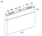
セルケース200は、電極体100を収容している。セルケース200には、図示略の電解液が収容されている。セルケース200は、密封されている。セルケース200は、ケース本体210と、蓋220と、を有している。The
ケース本体210は、上向きに開口する開口部を有している。ケース本体210は、アルミニウム等の金属からなる。図2に示されるように、ケース本体210は、底壁212と、周壁214と、を有している。底壁212は、矩形かつ平板状に形成されている。周壁214は、底壁212から起立している。周壁214は、四角筒状に形成されている。幅方向における周壁214の長さは、厚さ方向における周壁214の長さよりも長い。高さ方向における周壁214の長さは、厚さ方向における周壁214の長さよりも長い。The
蓋220は、ケース本体210の開口部を閉塞している。蓋220は、溶接等によって開口部に接続されている。蓋220は、平板状に形成されている。蓋220は、アルミニウム等の金属からなる。蓋220は、圧力解放弁222と、封止部材224と、を有している。The
圧力解放弁222は、蓋220の中央部に形成されている。圧力解放弁222は、セルケース200の内圧が所定圧以上となると破断するように形成されている。圧力解放弁222が破断することで、セルケース200内のガスが当該圧力解放弁222を通じてセルケース200外に放出されるため、セルケース200の内圧が低下する。The
封止部材224は、蓋220に形成された注液口hを封止している。注液口hは、蓄電セル1の製造過程において、セルケース200内に電解液を注入するための貫通孔である。注液口hは、当該注液口hを通じてケース本体210に電解液が注入された後、封止部材224によって封止される。The sealing
一対の外部端子300は、セルケース200上に固定されている。一対の外部端子300の一方は、正極の外部端子であり、他方は、負極の外部端子である。各外部端子300は、後述の上絶縁部510を介して蓋220の上面に固定されている。各外部端子300は、アルミニウム等の金属からなる。各外部端子300は、例えば、直方体形状に形成される。各外部端子300には、図示略のバスバーが溶接等によって接続される。A pair of
一対の連結部材400(図2を参照)は、複数の電極タブ112p,122nと外部端子300とを連結している。一方の連結部材400は、複数の正極タブ112pと正極の外部端子300とを連結しており、他方の連結部材400は、複数の負極タブ122nと負極の外部端子300とを連結している。一対の連結部材400の各々は、実質的に互いに同じ構造を有しているため、以下では一方の連結部材400について説明する。A pair of connecting members 400 (see FIG. 2) connects the
連結部材400は、集電タブ410と、サブタブ420と、連結ピン430と、を有している。The connecting
集電タブ410は、側方部412と、上方部414と、を有している。側方部412は、幅方向における電極体100の側方に位置している。上方部414は、電極体100の上方に位置している。上方部414は、側方部412の上端から幅方向における内側に向かって延びている。The
サブタブ420は、複数の正極タブ112pを集電タブ410に接続している。サブタブ420の一端部422は、溶接等によって複数の正極タブ112pに接続されており、サブタブ420の他端部424は、溶接等によって集電タブ410の側方部412に接続されている。The
連結ピン430は、集電タブ410と外部端子300とを連結している。連結ピン430は、上方部414と外部端子300とを連結している。具体的に、連結ピン430の下端部は、上方部414設けられた貫通孔に挿入された状態で上方部414に溶接等によって接続されており、連結ピン430の上端部は、外部端子300に設けられた貫通孔に挿入された状態で溶接やカシメ等によって外部端子300に接続されている。The connecting
絶縁部材500は、セルケース200と連結部材400との間を絶縁している。絶縁部材500は、上絶縁部510と、下絶縁部520と、インシュレータ530と、絶縁板540と、を有している。The insulating
上絶縁部510は、蓋220の上面に固定されている。上絶縁部510は、蓋220と外部端子300との間に配置されている。上絶縁部510には、連結ピン430を挿通させる挿通孔が設けられている。The upper insulating
下絶縁部520は、蓋220の下面に固定されている。下絶縁部520は、蓋220と、上方部414及び連結ピン430の下部と、の間に配置されている。下絶縁部520には、連結ピン430を挿通させる挿通孔が設けられている。The lower
インシュレータ530は、連結ピン430と蓋220との間に配置されている。インシュレータ530は、筒状に形成されており、連結ピン430を包囲している。The
絶縁板540は、上方部414の下面に固定されている。絶縁板540は、電極体100の上方に配置されている。絶縁板540のうち圧力解放弁222の下方に位置する部位、及び、注液口hの下方に位置する部位には、貫通孔が設けられている。The insulating
次に、図5~図9等を参照しながら、蓄電セル1の製造工程について説明する。Next, the manufacturing process of the storage cell 1 will be described with reference to Figures 5 to 9.
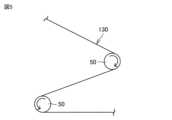
まず、図5に示されるように、ローラ50を用いてセパレータ130をつづら折り状に形成しながら、一対の介在部132a間に各電極110,120を交互に配置する。ローラ50は、図6に示されるように、クラウン状に形成されている。すなわち、ローラ50は、当該ローラ50の回転軸方向における端部から中央部52に向かうにしたがって拡径する形状に形成されている。このようにすれば、セパレータ130のつづら折り時に、幅方向(ローラ50の回転軸と平行な方向)におけるセパレータ130の中央部にシワが形成されることが抑制される。First, as shown in FIG. 5, the
そして、セパレータ130の最外被覆部132dを巻回した後、最外被覆部132dの外側から例えばレーザを照射することにより、終端132eを含む2層部132d1を各下折返し部132cに接続(溶着)するとともに各下折返し部132cを各負極集電箔122の下端部に接続(溶着)し、各上折返し部132bを最外被覆部132dに接続(溶着)する。このとき、終端132eが最初に接続されることが好ましい。なお、レーザの照射部に、非接触による加圧(ドライエアの噴射等)が加えられることが好ましい。Then, after winding the
次に、図7に示されるように、サブタブ420の一端部422を複数の電極タブ112p,122nに溶接等によって接続する。その後、図8において矢印で示されるように、サブタブ420の一端部422が集電タブ410の側方部412に接するように、一端部422及び複数の電極タブ112p,122nを折り曲げる。Next, as shown in FIG. 7, one
続いて、図9に示されるように、複数の電極110,120及びセパレータ130の周面と底面とをまとめて絶縁フィルム140で被覆した後、電極体100をケース本体210に挿入する。そして、蓋220の周縁部をケース本体210の開口部に溶接等によって接続する。Next, as shown in FIG. 9, the peripheral and bottom surfaces of the
その後、注液口hを通じてセルケース200内に電解液を供給し、注液口hを封止部材224で封止する。Then, electrolyte is supplied into the
以上に説明したように、本実施形態における電極体100では、最外被覆部132dに対する上折返し部132b及び下折返し部132cの相対変位が抑制されるため、電極110,120同士の位置ずれが抑制される。As described above, in the
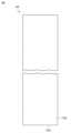
なお、図10に示されるように、電極体100は、電解液を保持可能な液保持部材150をさらに備えていてもよい。液保持部材150は、セパレータ130とは異なる部材である。液保持部材150は、例えば多孔材からなる。液保持部材150は、幅方向における複数の電極110,120及びセパレータ130の端部に設けられている。液保持部材150は、複数の電極110,120及びセパレータ130の上端部又は下端部に設けられてもよい。As shown in FIG. 10, the
上述した例示的な実施形態は、以下の態様の具体例であることが当業者により理解される。It will be understood by those skilled in the art that the exemplary embodiments described above are specific examples of the following aspects:
[態様1]
一方向に並ぶように配置された複数の電極と、
つづら折り状に形成されており、前記複数の電極の各々の間を絶縁するセパレータと、を備え、
前記セパレータは、
前記一方向に互いに隣接する一対の電極間に介在する複数の介在部と、
前記複数の介在部のうちの一の介在部の上端部と、前記複数の介在部のうち前記一方向における一方側に前記一の介在部に隣接する介在部の上端部と、を互いに連結する上折返し部と、
前記複数の介在部のうちの前記一の介在部の下端部と、前記複数の介在部のうち前記一方向における他方側に前記一の介在部に隣接する介在部の下端部と、を互いに連結する下折返し部と、
前記上折返し部及び前記下折返し部をまとめて被覆する最外被覆部と、を含み、
前記上折返し部は、前記最外被覆部に接続されており、
前記下折返し部は、前記最外被覆部に接続されている、電極体。 [Aspect 1]
A plurality of electrodes arranged in one direction;
a separator formed in a zigzag shape and insulating each of the plurality of electrodes;
The separator is
a plurality of intervening portions interposed between a pair of electrodes adjacent to each other in the one direction;
an upper folded portion connecting an upper end portion of one of the plurality of interposition portions and an upper end portion of another of the plurality of interposition portions adjacent to the one interposition portion on one side in the one direction;
a lower folded portion connecting a lower end portion of one of the plurality of interposition portions and a lower end portion of another of the plurality of interposition portions adjacent to the one interposition portion on the other side in the one direction;
an outermost covering portion that collectively covers the upper folded portion and the lower folded portion;
the upper folded portion is connected to the outermost covering portion,
The lower folded portion is connected to the outermost covering portion.
この電極体では、最外被覆部に対する上折返し部及び下折返し部の相対変位が抑制されるため、電極同士の位置ずれが抑制される。In this electrode body, the relative displacement of the upper and lower folded parts with respect to the outermost coating is suppressed, thereby suppressing misalignment of the electrodes.
[態様2]
前記最外被覆部は、前記上折返し部又は前記下折返し部と対向する位置に設けられた終端を含み、
前記終端は、前記電極と接続されている、態様1に記載の電極体。 [Aspect 2]
the outermost covering portion includes a terminal end provided at a position opposite the upper folded portion or the lower folded portion,
The electrode body of aspect 1, wherein the terminal end is connected to the electrode.
この態様では、最外被覆部の終端における接続強度が高まるため、終端からの剥離が抑制される。さらに、終端が一方向に電極と重ならないため、終端の存在に起因して電極に作用する面圧が不均一になることが抑制される。In this embodiment, the connection strength at the end of the outermost coating is increased, suppressing peeling from the end. Furthermore, because the end does not overlap with the electrode in one direction, uneven surface pressure acting on the electrode due to the presence of the end is suppressed.
[態様3]
前記最外被覆部は、2層で構成された2層部を含み、
前記2層部は、前記電極と接続されている、態様1又は2に記載の電極体。 [Aspect 3]
The outermost coating portion includes a two-layer portion composed of two layers,
The electrode assembly according to aspect 1 or 2, wherein the two-layer portion is connected to the electrode.
この態様では、セパレータに対する電極の位置ずれがより確実に抑制される。In this embodiment, the positional deviation of the electrodes relative to the separator is more reliably suppressed.
[態様4]
前記セパレータとは異なる部材であって、電解液を保持可能な液保持部材をさらに備え、
前記液保持部材は、上下方向における前記セパレータの端部、及び、前記一方向及び上下方向の双方と直交する幅方向における前記セパレータの端部の少なくとも一方に設けられている、態様1から3のいずれかに記載の電極体。 [Aspect 4]
The separator further includes a liquid retaining member capable of retaining an electrolyte, the liquid retaining member being different from the separator,
An electrode body described in any one of aspects 1 to 3, wherein the liquid retention member is provided on at least one of an end of the separator in the vertical direction and an end of the separator in a width direction perpendicular to both the one direction and the vertical direction.
[態様5]
態様1から4のいずれかに記載の電極体と、
前記電極体を収容するセルケースと、を備える、蓄電セル。 [Aspect 5]
An electrode assembly according to any one of aspects 1 to 4,
a cell case that houses the electrode assembly.
この態様では、負極電極から放出された電解液が液保持部材に保持されるため、その電解液を負極電極が吸収することにより、負極電極での電解液の不足が抑制される。In this embodiment, the electrolyte released from the negative electrode is retained in the electrolyte retention member, and the electrolyte is absorbed by the negative electrode, thereby preventing a shortage of electrolyte at the negative electrode.
なお、今回開示された実施形態はすべての点で例示であって、制限的なものではないと考えられるべきである。本発明の範囲は、上記した実施形態の説明ではなく特許請求の範囲によって示され、さらに特許請求の範囲と均等の意味および範囲内でのすべての変更が含まれる。It should be noted that the embodiments disclosed herein are illustrative in all respects and should not be considered limiting. The scope of the present invention is indicated by the claims rather than the description of the embodiments above, and further includes all modifications within the meaning and scope of the claims.
1 蓄電セル、100 電極体、110 正極電極、112 正極集電箔、112p 正極タブ、114 正極活物質層、120 負極電極、122 負極集電箔、122n 負極タブ、130 セパレータ、132a 介在部、132b 上折返し部、132c 下折返し部、132d 最外被覆部、132d1 2層部、132e 終端、140 絶縁フィルム、150 液保持部材、200 セルケース、210 ケース本体、220 蓋、300 外部端子、400 連結部材、410 集電タブ、420 サブタブ、430 連結ピン、500 絶縁部材、510 上絶縁部、520 下絶縁部、530 インシュレータ、540 絶縁板。1 storage cell, 100 electrode body, 110 positive electrode, 112 positive electrode current collector foil, 112p positive electrode tab, 114 positive electrode active material layer, 120 negative electrode, 122 negative electrode current collector foil, 122n negative electrode tab, 130 separator, 132a interposition portion, 132b upper folded portion, 132c lower folded portion, 132d outermost coating portion, 132d1 2-layer portion, 132e end, 140 insulating film, 150 liquid retention member, 200 cell case, 210 case body, 220 lid, 300 external terminal, 400 connecting member, 410 current collector tab, 420 sub-tab, 430 connecting pin, 500 insulating member, 510 upper insulating portion, 520 lower insulating portion, 530 Insulator, 540 insulating plate.
Claims (5)
Translated fromJapaneseつづら折り状に形成されており、前記複数の電極の各々の間を絶縁するセパレータと、を備え、
前記セパレータは、
前記一方向に互いに隣接する一対の電極間に介在する複数の介在部と、
前記複数の介在部のうちの一の介在部の上端部と、前記複数の介在部のうち前記一方向における一方側に前記一の介在部に隣接する介在部の上端部と、を互いに連結する上折返し部と、
前記複数の介在部のうちの前記一の介在部の下端部と、前記複数の介在部のうち前記一方向における他方側に前記一の介在部に隣接する介在部の下端部と、を互いに連結する下折返し部と、
前記上折返し部及び前記下折返し部をまとめて被覆する最外被覆部と、を含み、
前記上折返し部は、前記最外被覆部に接続されており、
前記下折返し部は、前記最外被覆部に接続されている、電極体。 A plurality of electrodes arranged in one direction;
a separator formed in a zigzag shape and insulating each of the plurality of electrodes;
The separator is
a plurality of intervening portions interposed between a pair of electrodes adjacent to each other in the one direction;
an upper folded portion connecting an upper end portion of one of the plurality of interposition portions and an upper end portion of another of the plurality of interposition portions adjacent to the one interposition portion on one side in the one direction;
a lower folded portion connecting a lower end portion of one of the plurality of interposition portions and a lower end portion of another of the plurality of interposition portions adjacent to the one interposition portion on the other side in the one direction;
an outermost covering portion that collectively covers the upper folded portion and the lower folded portion;
the upper folded portion is connected to the outermost covering portion,
The lower folded portion is connected to the outermost covering portion.
前記終端は、前記電極と接続されている、請求項1に記載の電極体。 the outermost covering portion includes a terminal end provided at a position opposite the upper folded portion or the lower folded portion,
The electrode body according to claim 1 , wherein the terminal end is connected to the electrode.
前記2層部は、前記電極と接続されている、請求項1又は2に記載の電極体。 The outermost coating portion includes a two-layer portion composed of two layers,
The electrode assembly according to claim 1 , wherein the two-layer portion is connected to the electrode.
前記液保持部材は、上下方向における前記セパレータの端部、及び、前記一方向及び上下方向の双方と直交する幅方向における前記セパレータの端部の少なくとも一方に設けられている、請求項1に記載の電極体。 The separator further includes a liquid retaining member capable of retaining an electrolyte, the liquid retaining member being different from the separator,
The electrode assembly according to claim 1 , wherein the liquid retaining member is provided on at least one of an end of the separator in a vertical direction and an end of the separator in a width direction perpendicular to both the one direction and the vertical direction.
前記電極体を収容するセルケースと、を備える、蓄電セル。 The electrode assembly according to claim 1 ,
a cell case that houses the electrode assembly.
Priority Applications (5)
| Application Number | Priority Date | Filing Date | Title |
|---|---|---|---|
| JP2023079356AJP2024163600A (en) | 2023-05-12 | 2023-05-12 | Electrode body and storage cell |
| EP24165061.3AEP4462534A1 (en) | 2023-05-12 | 2024-03-21 | Electrode assembly and power storage cell |
| US18/641,851US20240379992A1 (en) | 2023-05-12 | 2024-04-22 | Electrode assembly and power storage cell |
| KR1020240058963AKR20240164411A (en) | 2023-05-12 | 2024-05-03 | Electrode assembly and power storage cell |
| CN202410560603.0ACN118943667A (en) | 2023-05-12 | 2024-05-08 | Electrode body and electricity storage cell |
Applications Claiming Priority (1)
| Application Number | Priority Date | Filing Date | Title |
|---|---|---|---|
| JP2023079356AJP2024163600A (en) | 2023-05-12 | 2023-05-12 | Electrode body and storage cell |
Publications (1)
| Publication Number | Publication Date |
|---|---|
| JP2024163600Atrue JP2024163600A (en) | 2024-11-22 |
Family
ID=90417544
Family Applications (1)
| Application Number | Title | Priority Date | Filing Date |
|---|---|---|---|
| JP2023079356APendingJP2024163600A (en) | 2023-05-12 | 2023-05-12 | Electrode body and storage cell |
Country Status (5)
| Country | Link |
|---|---|
| US (1) | US20240379992A1 (en) |
| EP (1) | EP4462534A1 (en) |
| JP (1) | JP2024163600A (en) |
| KR (1) | KR20240164411A (en) |
| CN (1) | CN118943667A (en) |
Citations (4)
| Publication number | Priority date | Publication date | Assignee | Title |
|---|---|---|---|---|
| JP2019102258A (en)* | 2017-12-01 | 2019-06-24 | 株式会社Gsユアサ | Power storage element |
| JP2019145287A (en)* | 2018-02-19 | 2019-08-29 | トヨタ自動車株式会社 | Sealed battery |
| US20220407185A1 (en)* | 2021-06-16 | 2022-12-22 | Samsung Sdi Co., Ltd. | Rechargeable secondary battery |
| US20230027024A1 (en)* | 2021-07-09 | 2023-01-26 | Lg Energy Solution, Ltd. | Electrode Assembly |
Family Cites Families (7)
| Publication number | Priority date | Publication date | Assignee | Title |
|---|---|---|---|---|
| KR100309604B1 (en)* | 1999-12-20 | 2001-11-03 | 홍지준 | Lithium secondary battery |
| JP2013145678A (en)* | 2012-01-13 | 2013-07-25 | Hitachi Maxell Ltd | Nonaqueous electrolyte secondary battery |
| KR101663351B1 (en)* | 2013-10-31 | 2016-10-06 | 주식회사 엘지화학 | Cell for electrochemical device and preparation method thereof |
| WO2017149991A1 (en) | 2016-02-29 | 2017-09-08 | パナソニックIpマネジメント株式会社 | Stacked nonaqueous electrolyte secondary battery |
| US20200243895A1 (en)* | 2017-09-29 | 2020-07-30 | Envision Aesc Energy Devices Ltd. | Secondary battery |
| EP3920295A4 (en)* | 2019-01-29 | 2022-08-17 | Panasonic Holdings Corporation | STACKED SECONDARY BATTERY |
| US20240283003A1 (en)* | 2021-10-07 | 2024-08-22 | Lg Energy Solution, Ltd. | Electrode Assembly and Battery Cell Including the Same |
- 2023
- 2023-05-12JPJP2023079356Apatent/JP2024163600A/enactivePending
- 2024
- 2024-03-21EPEP24165061.3Apatent/EP4462534A1/enactivePending
- 2024-04-22USUS18/641,851patent/US20240379992A1/enactivePending
- 2024-05-03KRKR1020240058963Apatent/KR20240164411A/enactivePending
- 2024-05-08CNCN202410560603.0Apatent/CN118943667A/enactivePending
Patent Citations (5)
| Publication number | Priority date | Publication date | Assignee | Title |
|---|---|---|---|---|
| JP2019102258A (en)* | 2017-12-01 | 2019-06-24 | 株式会社Gsユアサ | Power storage element |
| JP2019145287A (en)* | 2018-02-19 | 2019-08-29 | トヨタ自動車株式会社 | Sealed battery |
| US20220407185A1 (en)* | 2021-06-16 | 2022-12-22 | Samsung Sdi Co., Ltd. | Rechargeable secondary battery |
| US20230027024A1 (en)* | 2021-07-09 | 2023-01-26 | Lg Energy Solution, Ltd. | Electrode Assembly |
| US20230028439A1 (en)* | 2021-07-09 | 2023-01-26 | Lg Energy Solution, Ltd. | Assembly Manufacturing Equipment and Method for Electrode Assembly |
Also Published As
| Publication number | Publication date |
|---|---|
| CN118943667A (en) | 2024-11-12 |
| KR20240164411A (en) | 2024-11-19 |
| US20240379992A1 (en) | 2024-11-14 |
| EP4462534A1 (en) | 2024-11-13 |
Similar Documents
| Publication | Publication Date | Title |
|---|---|---|
| CN111354914B (en) | Traceless welding method and welding structure and products of button battery pole shell and electrode tab | |
| CN111354912B (en) | Electric connection method, electric connection structure and product of button cell pole shell and electrode lug | |
| CN211578865U (en) | Button cell pole shell and electrode lug seamless welding structure | |
| JP2024163600A (en) | Electrode body and storage cell | |
| CN210984846U (en) | Button cell pole shell and electrode lug seamless welding structure | |
| JP2024163599A (en) | Electrode body | |
| JP2024169062A (en) | Energy storage cell | |
| JP7708145B2 (en) | Manufacturing method of the electrode body | |
| JP7609150B2 (en) | Method for manufacturing storage cell and storage cell | |
| JP2025008515A (en) | Method for manufacturing storage cell and electrode assembly | |
| JP7622724B2 (en) | Energy storage cell | |
| JP2025001306A (en) | Power storage cell | |
| JP2024179095A (en) | Energy storage cell | |
| CN222088304U (en) | Electrode body | |
| JP7736030B2 (en) | Energy storage cell | |
| CN211700458U (en) | Button cell with no trace welded structure | |
| CN210956886U (en) | Button cell with no trace welded structure | |
| JP2024179090A (en) | Energy storage cell | |
| JP7622721B2 (en) | Energy storage cell | |
| CN211578869U (en) | Button cell pole shell and electrode lug electric connection structure | |
| JP2024165644A (en) | Manufacturing method of the electrode body | |
| CN211578902U (en) | Button cell with no trace welded structure | |
| JP2024088108A (en) | Energy storage cell | |
| JP2024114212A (en) | Secondary battery | |
| JP2024071998A (en) | Energy storage cell |
Legal Events
| Date | Code | Title | Description |
|---|---|---|---|
| A621 | Written request for application examination | Free format text:JAPANESE INTERMEDIATE CODE: A621 Effective date:20240709 | |
| A131 | Notification of reasons for refusal | Free format text:JAPANESE INTERMEDIATE CODE: A131 Effective date:20250701 | |
| A521 | Request for written amendment filed | Free format text:JAPANESE INTERMEDIATE CODE: A523 Effective date:20250814 |