JP2024156770A - BLOOD SAMPLE OPTIMIZATION SYSTEM AND BLOOD CONTAMINANT ISOLATION DEVICE AND METHOD - Patent application - Google Patents
BLOOD SAMPLE OPTIMIZATION SYSTEM AND BLOOD CONTAMINANT ISOLATION DEVICE AND METHOD - Patent applicationDownload PDFInfo
- Publication number
- JP2024156770A JP2024156770AJP2024121200AJP2024121200AJP2024156770AJP 2024156770 AJP2024156770 AJP 2024156770AJP 2024121200 AJP2024121200 AJP 2024121200AJP 2024121200 AJP2024121200 AJP 2024121200AJP 2024156770 AJP2024156770 AJP 2024156770A
- Authority
- JP
- Japan
- Prior art keywords
- blood
- isolation
- chamber
- isolation chamber
- air permeable
- Prior art date
- Legal status (The legal status is an assumption and is not a legal conclusion. Google has not performed a legal analysis and makes no representation as to the accuracy of the status listed.)
- Granted
Links
Images


Classifications
- A—HUMAN NECESSITIES
- A61—MEDICAL OR VETERINARY SCIENCE; HYGIENE
- A61B—DIAGNOSIS; SURGERY; IDENTIFICATION
- A61B5/00—Measuring for diagnostic purposes; Identification of persons
- A61B5/15—Devices for taking samples of blood
- A61B5/150007—Details
- A61B5/150755—Blood sample preparation for further analysis, e.g. by separating blood components or by mixing
- A—HUMAN NECESSITIES
- A61—MEDICAL OR VETERINARY SCIENCE; HYGIENE
- A61B—DIAGNOSIS; SURGERY; IDENTIFICATION
- A61B5/00—Measuring for diagnostic purposes; Identification of persons
- A61B5/15—Devices for taking samples of blood
- A61B5/150007—Details
- A61B5/150015—Source of blood
- A61B5/15003—Source of blood for venous or arterial blood
- A—HUMAN NECESSITIES
- A61—MEDICAL OR VETERINARY SCIENCE; HYGIENE
- A61B—DIAGNOSIS; SURGERY; IDENTIFICATION
- A61B5/00—Measuring for diagnostic purposes; Identification of persons
- A61B5/15—Devices for taking samples of blood
- A61B5/150007—Details
- A61B5/150206—Construction or design features not otherwise provided for; manufacturing or production; packages; sterilisation of piercing element, piercing device or sampling device
- A61B5/150213—Venting means
- A—HUMAN NECESSITIES
- A61—MEDICAL OR VETERINARY SCIENCE; HYGIENE
- A61B—DIAGNOSIS; SURGERY; IDENTIFICATION
- A61B5/00—Measuring for diagnostic purposes; Identification of persons
- A61B5/15—Devices for taking samples of blood
- A61B5/150007—Details
- A61B5/150206—Construction or design features not otherwise provided for; manufacturing or production; packages; sterilisation of piercing element, piercing device or sampling device
- A61B5/150221—Valves
- A—HUMAN NECESSITIES
- A61—MEDICAL OR VETERINARY SCIENCE; HYGIENE
- A61B—DIAGNOSIS; SURGERY; IDENTIFICATION
- A61B5/00—Measuring for diagnostic purposes; Identification of persons
- A61B5/15—Devices for taking samples of blood
- A61B5/150007—Details
- A61B5/150206—Construction or design features not otherwise provided for; manufacturing or production; packages; sterilisation of piercing element, piercing device or sampling device
- A61B5/150251—Collection chamber divided into at least two compartments, e.g. for division of samples
- A—HUMAN NECESSITIES
- A61—MEDICAL OR VETERINARY SCIENCE; HYGIENE
- A61B—DIAGNOSIS; SURGERY; IDENTIFICATION
- A61B5/00—Measuring for diagnostic purposes; Identification of persons
- A61B5/15—Devices for taking samples of blood
- A61B5/150007—Details
- A61B5/150206—Construction or design features not otherwise provided for; manufacturing or production; packages; sterilisation of piercing element, piercing device or sampling device
- A61B5/150274—Manufacture or production processes or steps for blood sampling devices
- A—HUMAN NECESSITIES
- A61—MEDICAL OR VETERINARY SCIENCE; HYGIENE
- A61B—DIAGNOSIS; SURGERY; IDENTIFICATION
- A61B5/00—Measuring for diagnostic purposes; Identification of persons
- A61B5/15—Devices for taking samples of blood
- A61B5/150007—Details
- A61B5/150351—Caps, stoppers or lids for sealing or closing a blood collection vessel or container, e.g. a test-tube or syringe barrel
- A—HUMAN NECESSITIES
- A61—MEDICAL OR VETERINARY SCIENCE; HYGIENE
- A61B—DIAGNOSIS; SURGERY; IDENTIFICATION
- A61B5/00—Measuring for diagnostic purposes; Identification of persons
- A61B5/15—Devices for taking samples of blood
- A61B5/150007—Details
- A61B5/150763—Details with identification means
- A61B5/150786—Optical identification systems, e.g. bar codes, colour codes
- A—HUMAN NECESSITIES
- A61—MEDICAL OR VETERINARY SCIENCE; HYGIENE
- A61B—DIAGNOSIS; SURGERY; IDENTIFICATION
- A61B5/00—Measuring for diagnostic purposes; Identification of persons
- A61B5/15—Devices for taking samples of blood
- A61B5/150007—Details
- A61B5/150946—Means for varying, regulating, indicating or limiting the speed or time of blood collection
- A—HUMAN NECESSITIES
- A61—MEDICAL OR VETERINARY SCIENCE; HYGIENE
- A61B—DIAGNOSIS; SURGERY; IDENTIFICATION
- A61B5/00—Measuring for diagnostic purposes; Identification of persons
- A61B5/15—Devices for taking samples of blood
- A61B5/150992—Blood sampling from a fluid line external to a patient, such as a catheter line, combined with an infusion line; Blood sampling from indwelling needle sets, e.g. sealable ports, luer couplings or valves
- A—HUMAN NECESSITIES
- A61—MEDICAL OR VETERINARY SCIENCE; HYGIENE
- A61B—DIAGNOSIS; SURGERY; IDENTIFICATION
- A61B5/00—Measuring for diagnostic purposes; Identification of persons
- A61B5/15—Devices for taking samples of blood
- A61B5/153—Devices specially adapted for taking samples of venous or arterial blood, e.g. with syringes
- A61B5/1535—Devices specially adapted for taking samples of venous or arterial blood, e.g. with syringes comprising means for indicating vein or arterial entry
- A—HUMAN NECESSITIES
- A61—MEDICAL OR VETERINARY SCIENCE; HYGIENE
- A61B—DIAGNOSIS; SURGERY; IDENTIFICATION
- A61B5/00—Measuring for diagnostic purposes; Identification of persons
- A61B5/15—Devices for taking samples of blood
- A61B5/153—Devices specially adapted for taking samples of venous or arterial blood, e.g. with syringes
- A61B5/154—Devices using pre-evacuated means
- A61B5/1545—Devices using pre-evacuated means comprising means for indicating vein or arterial entry
- A—HUMAN NECESSITIES
- A61—MEDICAL OR VETERINARY SCIENCE; HYGIENE
- A61B—DIAGNOSIS; SURGERY; IDENTIFICATION
- A61B5/00—Measuring for diagnostic purposes; Identification of persons
- A61B5/15—Devices for taking samples of blood
- A61B5/150007—Details
- A61B5/150374—Details of piercing elements or protective means for preventing accidental injuries by such piercing elements
- A61B5/150381—Design of piercing elements
- A61B5/150389—Hollow piercing elements, e.g. canulas, needles, for piercing the skin
- A—HUMAN NECESSITIES
- A61—MEDICAL OR VETERINARY SCIENCE; HYGIENE
- A61B—DIAGNOSIS; SURGERY; IDENTIFICATION
- A61B5/00—Measuring for diagnostic purposes; Identification of persons
- A61B5/15—Devices for taking samples of blood
- A61B5/150007—Details
- A61B5/150374—Details of piercing elements or protective means for preventing accidental injuries by such piercing elements
- A61B5/150381—Design of piercing elements
- A61B5/150473—Double-ended needles, e.g. used with pre-evacuated sampling tubes
- A61B5/150488—Details of construction of shaft
- A—HUMAN NECESSITIES
- A61—MEDICAL OR VETERINARY SCIENCE; HYGIENE
- A61B—DIAGNOSIS; SURGERY; IDENTIFICATION
- A61B5/00—Measuring for diagnostic purposes; Identification of persons
- A61B5/15—Devices for taking samples of blood
- A61B5/157—Devices characterised by integrated means for measuring characteristics of blood
Landscapes
- Health & Medical Sciences (AREA)
- Life Sciences & Earth Sciences (AREA)
- Engineering & Computer Science (AREA)
- Medical Informatics (AREA)
- Surgery (AREA)
- Hematology (AREA)
- Biophysics (AREA)
- Pathology (AREA)
- Biomedical Technology (AREA)
- Heart & Thoracic Surgery (AREA)
- Veterinary Medicine (AREA)
- Molecular Biology (AREA)
- Physics & Mathematics (AREA)
- Animal Behavior & Ethology (AREA)
- General Health & Medical Sciences (AREA)
- Public Health (AREA)
- Manufacturing & Machinery (AREA)
- Vascular Medicine (AREA)
- Sampling And Sample Adjustment (AREA)
- Measurement Of The Respiration, Hearing Ability, Form, And Blood Characteristics Of Living Organisms (AREA)
- Investigating Or Analysing Biological Materials (AREA)
Abstract
Description
Translated fromJapanese 菌血症は、血液中に微生物が存在することである。一方、敗血症は、発熱、頻脈、頻呼
吸及び低血圧などの臨床症状及び臨床兆候がある場合の菌血症である。菌血症及び敗血症
は、高い死亡率、入院発生率及び入院期間と関連する費用の増加とを伴う。多くの菌血症
、敗血症、真菌血症及び他の病原体が実際に病院又は他の医療施設内で発生し、カテーテ
ル及び静脈穿刺がこれらの病原体の潜在的なキャリアとしての汚染源である。 Bacteremia is the presence of microorganisms in the blood, whereas sepsis is bacteremia with clinical symptoms and signs such as fever, tachycardia, tachypnea and hypotension. Bacteremia and sepsis are associated with high mortality, hospitalization incidence and length of stay and associated costs. Many bacteremias, sepsis, fungemias and other pathogens actually occur within hospitals or other healthcare facilities, with catheters and venipunctures being sources of contamination as potential carriers of these pathogens.
血液培養は、患者の血液中の菌血症及び敗血症に関連する微生物病原体を検出するのに
使用される標準検査である。血液培養という用語は、血液が1つ以上の血液培養ボトル又
は容器に接種される、末梢部位又は中心ライン又は動脈ラインからの1回の静脈穿刺を指
す。1つのボトルが1つの血液培養と見なされ、2つ以上がセットと見なされる。複数の
セットは複数の静脈穿刺から得られ、患者の異なる部位に関連する。 Blood culture is the standard test used to detect microbial pathogens associated with bacteremia and sepsis in a patient's blood. The term blood culture refers to a single venipuncture from a peripheral site or a central or arterial line in which blood is inoculated into one or more blood culture bottles or containers. One bottle is considered one blood culture, two or more are considered a set. Multiple sets are obtained from multiple venipunctures and are associated with different sites on the patient.
これらの方法は、敗血症を管理する上で重要な要素である微生物同定及び感受性検査を
可能にするが、迅速な結果が得られないことと厄介な病原体に対する感度が低いことが、
改良されたシステムの開発及び補助的な分子検査又はプロテオミクス検査につながってい
る。 Although these methods allow for microbial identification and susceptibility testing, which are important components in managing sepsis, they are limited by a lack of rapid results and low sensitivity for fastidious pathogens.
This has led to the development of improved systems and complementary molecular or proteomic tests.
血液培養を行うための血液サンプルの採取は、現代の患者ケアの重要な要素であり、正
確な診断を提供することによって患者の結果に良い影響を与えることも、不必要な抗菌療
法を長引かせ、入院期間を長くし、コストを増加させることによって結果に悪影響を与え
ることもある。 Obtaining blood samples to perform blood cultures is a critical component of modern patient care and can either positively impact patient outcome by providing an accurate diagnosis or negatively impact outcome by prolonging unnecessary antimicrobial therapy, increasing hospital length of stay, and increasing costs.
血液培養の採取の1つの結果は、汚染である。血液培養の汚染は、偽陽性の培養結果及
び/又は医療関連コストの著しい増加につながる可能性がある。血液培養の汚染の原因は
、不適切な皮膚消毒、不適切な採取管の消毒、最初の採血の汚染を含み、これらは結果を
歪める可能性がある。 One consequence of blood culture collection is contamination. Contamination of blood cultures can lead to false positive culture results and/or significantly increased healthcare-related costs. Causes of blood culture contamination include improper skin preparation, improper collection tube disinfection, and contamination of the initial blood draw, which can skew the results.
血液培養採取キットは、一般に、BD、スミス、ビー・ブラウンなどの会社によって提
供される「バタフライ」セット、輸液セット、又は他のタイプの静脈穿刺デバイスと、好
気性血液培養ボトル及び嫌気性血液培養ボトルとで構成される。様々な異なるボトルも検
査要件に応じて利用可能である。これらのボトルは、好気性生物と嫌気性生物の両方の回
収を最適化するように特別に設計されている。従来のキットでは、使用されるボトルは一
般に「バキュテナー(登録商標)」として知られており、これは、所定の量の血液などの
液体の採取を容易にするべく管の内部に真空を作り出すために排気される蓋を備える滅菌
ガラス管又は滅菌プラスチック管から形成される採血管である。 Blood culture collection kits generally consist of a "butterfly" set, an infusion set, or other type of venipuncture device provided by companies such as BD, Smith, B. Braun, and aerobic and anaerobic blood culture bottles. A variety of different bottles are also available depending on the test requirements. These bottles are specifically designed to optimize the recovery of both aerobic and anaerobic organisms. In conventional kits, the bottles used are commonly known as "Vacutainers," which are blood collection tubes formed from sterile glass or plastic tubes with a cap that is evacuated to create a vacuum inside the tube to facilitate the collection of a predetermined amount of liquid, such as blood.
偽陽性の血液培養は、一般的に、不十分なサンプリング技術の結果である。それらは、
必要でないときに抗生物質を使用させ、病院費及び患者の不安を増大させる。血液培養は
、皮膚内への針刺しから採取され、その後で血液のサンプルを取り込むためにバキュテナ
ー(登録商標)が取り付けられる。汚染は、穿刺部位及びその周辺の皮膚領域の不適切又
は不完全な消毒によって生じ得る。それはまた、挿入中の針による皮膚のくりぬきから、
くりぬかれた皮膚細胞と関連する汚染物質とがサンプル中に引き込まれることで生じるこ
ともある。 False-positive blood cultures are commonly the result of poor sampling techniques. They include:
It causes antibiotics to be used when not necessary, increasing hospital costs and patient anxiety. Blood cultures are taken from a needle prick into the skin, after which a Vacutainer® is placed to capture the blood sample. Contamination can occur from improper or incomplete disinfection of the puncture site and the surrounding skin area. It can also result from the needle gouging the skin during insertion.
This can also occur when excised skin cells and associated contaminants are drawn into the sample.
皮下注射針を通る血流は層流であり、このため、皮下注射針に圧力降下が加えられると
きに流管にわたって流速勾配が発生する。血液を強く吸引するか又は非常に小さな皮下注
射針を使用すると、溶解及び赤血球からのカリウムの放出が起こり、それにより血液サン
プルが異常になる可能性がある。 Blood flow through a hypodermic needle is laminar, which creates a flow velocity gradient across the flow tube when a pressure drop is applied across the hypodermic needle. Using a strong blood draw or a very small hypodermic needle can cause lysis and release of potassium from red blood cells, resulting in an abnormal blood sample.
他の例では、一部の患者は繊細な静脈を有し、繊細な静脈は、特に患者の状態に対して
あまりにも急速に引き出される注射器のプランジャによって加えられるような圧力低下又
は真空の下で崩壊し得る。このような状態は事前に知ることが不可能であるため、このよ
うな静脈崩壊は危険であり、制御することは非常に困難である。 In another example, some patients have delicate veins that may collapse under a pressure drop or vacuum, such as that exerted by a syringe plunger that is withdrawn too quickly, especially for the patient's condition. Because such conditions are impossible to know about in advance, such vein collapse is dangerous and very difficult to control.
血液培養の汚染率を低下させるために、例えば、無菌採取技術に関するスタッフの訓練
、汚染率に関するフィードバック、及び血液培養採取キットの導入など、様々な戦略が実
施されている。皮膚消毒は汚染の心配を減らすことができるが、20%以上の皮膚の微生
物は真皮の深部に位置し、消毒の影響を受けない。ボトル接種の前に針を交換することは
、汚染率を低下させることなく針刺し損傷を受ける危険性を高めるので推奨されない。 Various strategies have been implemented to reduce blood culture contamination rates, such as training staff on aseptic collection technique, feedback on contamination rates, and the introduction of blood culture collection kits. Skin disinfection can reduce contamination concerns, but more than 20% of skin microorganisms are located deep in the dermis and are not affected by disinfection. Needle replacement before bottle inoculation is not recommended as it increases the risk of needlestick injury without reducing contamination rates.
血液培養の汚染を低減するための一部の従来のシステム及び技術は、中心静脈カテーテ
ル、静脈穿刺及び他の血管アクセスシステムから採取された最初のアリコートの血液を捨
てることを含む。しかしながら、これらのシステムは、ユーザーが血管内デバイスを機械
的に操作することを必要とするか又は確実にすることが困難な複雑な一連のステップを踏
むこと必要とする。 Some conventional systems and techniques for reducing blood culture contamination include discarding the first aliquot of blood drawn from central venous catheters, venipunctures, and other vascular access systems, however, these systems require the user to mechanically manipulate an intravascular device or follow a complex series of steps that are difficult to ensure.
本明細書は、血液培養の汚染、細胞の溶解、及び静脈崩壊を低減するためのシステム及
び方法を提示する。一部の実施では、システム及び方法は、ユーザーの消毒のばらつきを
なくし、また皮膚細胞が血液培養サンプルに入り込む危険性をなくすこともできる。本明
細書に開示されたシステム及び方法は、汚染物質のない血液サンプルを採取するためにバ
キュテナー(登録商標)又は他の採血デバイス(すなわち、注射器)をいつ取り付けるべ
きかを潜在的に示す以外は、既存の臨床プロセスの変更を必要としない。 Presented herein are systems and methods for reducing blood culture contamination, cellular lysis, and vein collapse. In some implementations, the systems and methods eliminate user sterilization variability and may also eliminate the risk of skin cells being introduced into blood culture samples. The systems and methods disclosed herein do not require changes to existing clinical processes other than potentially indicating when to attach a Vacutainer® or other blood collection device (i.e., syringe) to obtain a contaminant-free blood sample.
本明細書に開示されたシステム及び方法の一部の実施では、採血は、患者自身の血圧の
使用によって受動的に成し遂げられ、それによって静脈崩壊の危険性を低減し、現行の実
務を超える更なるユーザーのステップを排除する。システム及び方法は、短経路の直接刺
し又はバタフライ静脈穿刺システムに適合するように適用されることができる。カテーテ
ルを通して採取されたサンプルと共に使用されることもできる。 In some implementations of the systems and methods disclosed herein, blood collection is accomplished passively through the use of the patient's own blood pressure, thereby reducing the risk of venous collapse and eliminating additional user steps beyond current practice. The systems and methods can be adapted to fit short-path direct stick or butterfly venipuncture systems. They can also be used with samples collected through a catheter.
一態様では、血液隔離デバイスが提示されている。血液隔離デバイスは、入口ポートと
出口ポートとを含む。血液隔離デバイスは、入口ポートと接続される隔離チャンバであっ
て、空気透過性血液バリアを含む通気口を有する隔離チャンバをさらに含む。血液隔離デ
バイスは、入口ポートと接続される近位端と、出口ポートと接続される遠位端とを有する
、サンプリング流路をさらに含む。 In one aspect, a blood isolation device is presented. The blood isolation device includes an inlet port and an outlet port. The blood isolation device further includes an isolation chamber connected to the inlet port, the isolation chamber having an air vent including an air permeable blood barrier. The blood isolation device further includes a sampling flow path having a proximal end connected to the inlet port and a distal end connected to the outlet port.
別の態様では、採血経路と接続される血液隔離デバイスが記載されている。採血経路は
、患者針とサンプル採取デバイスとを有する。血液隔離デバイスは、患者針と接続される
入口ポートと、入口ポートと接続される隔離チャンバであって、空気透過性血液バリアを
含む通気口を有する隔離チャンバとを含む。血液隔離デバイスは、入口ポートと接続され
る近位端を有するサンプリング流路と、サンプリング流路の遠位端及びサンプル採取デバ
イスと接続される出口ポートとをさらに含む。 In another aspect, a blood isolation device is described for connection with a blood collection pathway. The blood collection pathway has a patient needle and a sample collection device. The blood isolation device includes an inlet port connected to the patient needle and an isolation chamber connected to the inlet port, the isolation chamber having an air port including an air permeable blood barrier. The blood isolation device further includes a sampling flow path having a proximal end connected to the inlet port and an outlet port connected to a distal end of the sampling flow path and to the sample collection device.
さらに別の態様では、採血システムと接続される血液隔離デバイスが記載されている。
採血システムは、患者から血液サンプルを取り出せるようにするための患者針と、密封さ
れかつ真空採血管を受け入れるように適合されたサンプル針とを含む。血液隔離デバイス
は、患者からの血液サンプルを受け入れるために患者針と接続される入口ポートを含む。
血液隔離デバイスは、入口ポートと接続されかつ空気透過性血液バリアを含む通気口を有
する隔離チャンバであって、サンプル針が真空採血管によって開封されるより前に血液サ
ンプルの最初の部分を受け入れかつ隔離する隔離チャンバをさらに含む。血液隔離デバイ
スは、入口ポートと接続される近位端を有するサンプリング流路であって、真空採血管に
よってサンプル針が開封されると血液サンプルの後続の部分を運ぶサンプリング流路をさ
らに含む。血液隔離デバイスは、血液サンプルの後続の部分をサンプル針に運ぶためにサ
ンプリング流路の遠位端と接続される出口ポートをさらに含む。 In yet another aspect, a blood isolation device for connection with a blood collection system is described.
The blood collection system includes a patient needle for allowing a blood sample to be drawn from a patient, and a sample needle that is sealed and adapted to receive an evacuated blood collection tube. The blood isolation device includes an inlet port that connects with the patient needle to receive the blood sample from the patient.
The blood isolation device further includes an isolation chamber having a vent connected to the inlet port and including an air permeable blood barrier to receive and isolate an initial portion of the blood sample before the sample needle is opened by the evacuated blood collection tube.The blood isolation device further includes a sampling channel having a proximal end connected to the inlet port to carry a subsequent portion of the blood sample once the sample needle is opened by the evacuated blood collection tube.The blood isolation device further includes an outlet port connected to a distal end of the sampling channel for carrying the subsequent portion of the blood sample to the sample needle.
さらに別の態様では、血液サンプル最適化システムが開示され、記載されている。血液
サンプル最適化システムは、患者の血液の1つ以上のサンプルを取り出せるようにしかつ
得るための採血システムと、静脈穿刺プロセスによって汚染されている恐れがありかつ患
者の血液中の病原体の偽陽性同定をもたらす可能性がある患者の血液の1つ以上のサンプ
ルの最初の部分を受け入れかつ隔離するための血液隔離デバイスとを含む。 In yet another aspect, a blood sample optimization system is disclosed and described that includes a blood collection system for enabling and obtaining one or more samples of a patient's blood, and a blood isolation device for receiving and isolating an initial portion of the one or more samples of the patient's blood that may have been contaminated by the venipuncture process and may result in a false positive identification of a pathogen in the patient's blood.
採血システムは、患者の血液のサンプルを取り出せるようにするために患者の静脈穿刺
用に構成された患者針と、血液サンプルを運ぶために患者針と接続される採血経路と、血
液サンプルの後続の部分を採取しかつ収容するために真空採血容器を受け入れるように構
成されたサンプル針とを含む。 The blood collection system includes a patient needle configured for venipuncture of a patient to allow removal of a sample of the patient's blood, a blood collection pathway connected to the patient needle for carrying the blood sample, and a sample needle configured to receive an evacuated blood collection container for collecting and containing a subsequent portion of the blood sample.
さらに別の態様では、血液隔離デバイスが開示され、記載されている。一部の実施では
、血液隔離デバイスは、入口ポートと、入口ポートと接続される出口ポートと、入口ポー
トと接続される隔離チャンバとを含むことができる。隔離チャンバは、空気透過性血液バ
リアを含む通気口を有することができる。 In yet another aspect, a blood isolation device is disclosed and described. In some implementations, the blood isolation device can include an inlet port, an outlet port connected to the inlet port, and an isolation chamber connected to the inlet port. The isolation chamber can have an air vent that includes an air permeable blood barrier.
一態様における血液隔離デバイスは、入口ポートと、出口ポートと、分岐点を介して入
口ポートと接続された隔離チャンバと、分岐点を介して入口ポートと接続された近位端と
出口ポートと接続された遠位端とを有するサンプリング流路とを含むことができ、隔離チ
ャンバは空気透過性血液バリアを含む通気口を有し、通気口は空気透過性血液バリアを少
なくとも部分的に囲みかつ1つ以上の空気孔を含む外壁によって画定され、通気口は、壁
を少なくとも部分的に覆うキャップと、隔離チャンバに空気が入るのを阻止する空気透過
性血液バリアに隣接する一方向シールとをさらに含む。特定の関連する態様では、隔離チ
ャンバ、サンプリング流路及び分岐点は、血液の第1の部分が隔離チャンバへの隔離のた
めに空気透過性血液バリアに向かって隔離チャンバに流れ込み、血液の第2の部分が隔離
チャンバ及び隔離チャンバ内に隔離された血液の第1の部分を迂回し、出口ポートに向か
ってサンプリング流路に導かれるように寸法設定されかつ構成される。 A blood isolation device in one aspect can include an inlet port, an outlet port, an isolation chamber connected to the inlet port through a branch point, and a sampling flow path having a proximal end connected to the inlet port through a branch point and a distal end connected to the outlet port, the isolation chamber having an air vent including an air permeable blood barrier, the air vent being defined by an outer wall at least partially surrounding the air permeable blood barrier and including one or more air holes, the air vent further including a cap at least partially covering the wall and a one-way seal adjacent the air permeable blood barrier that prevents air from entering the isolation chamber. In certain related aspects, the isolation chamber, sampling flow path and branch point are sized and configured such that a first portion of blood flows into the isolation chamber toward the air permeable blood barrier for isolation into the isolation chamber, and a second portion of blood bypasses the isolation chamber and the first portion of blood sequestered within the isolation chamber and is directed to the sampling flow path toward the outlet port.
別の態様では、サンプリング流路及び分岐点は、血液の第1の部分が隔離チャンバに流
入して隔離チャンバを満たし、通気口を通して隔離チャンバ内の空気を追い出し、血液の
第2の部分が隔離チャンバ及び隔離チャンバ内に隔離された血液の第1の部分を迂回し、
出口ポートに向かってサンプリング流路に導かれるように寸法設定されかつ構成される。 In another aspect, the sampling flow path and branch point are configured such that a first portion of the blood flows into the isolation chamber to fill the isolation chamber, and air within the isolation chamber is expelled through the vent, and a second portion of the blood bypasses the isolation chamber and the first portion of the blood sequestered within the isolation chamber;
The sampling flow path is sized and configured to be directed toward the outlet port.
特定の態様における血液隔離及びサンプリングシステム隔離デバイスは、近位端に患者
針を、遠位端にサンプル採取デバイスを有する採血経路と、採血経路の近位端と遠位端と
の間で採血経路に取り付けられた血液隔離デバイスとを含むことができる。一態様におけ
る血液隔離デバイスは、患者針の方を向いて採血経路に連結された入口ポートと、サンプ
ル採取デバイスの方を向いて採血経路に連結された出口ポートと、分岐点を介して入口ポ
ートと接続された隔離チャンバと、分岐点を介して入口ポートと接続された近位端と出口
ポートと接続された遠位端とを有するサンプリング流路とを含むことができ、隔離チャン
バは空気透過性血液バリアを含む通気口を有し、通気口は、空気透過性血液バリアを少な
くとも部分的に囲みかつ1つ以上の空気孔を含む外壁によって画定され、通気口は、壁を
少なくとも部分的に覆うキャップと、空気が隔離チャンバに入るのを阻止する空気透過性
血液バリアに隣接する一方向シールとをさらに含む。特定の関連する態様では、隔離チャ
ンバ、サンプリング流路及び分岐点は、血液の第1の部分が隔離チャンバへの隔離のため
に空気透過性血液バリアに向かって隔離チャンバに流れ込み、血液の第2の部分が隔離チ
ャンバ及び隔離チャンバ内に隔離された血液の第1の部分を迂回し、出口ポートに向かっ
てサンプリング流路に導かれるように寸法設定されかつ構成されることができる。 In certain aspects, the blood isolation and sampling system isolation device can include a blood collection pathway having a patient needle at a proximal end and a sample collection device at a distal end, and a blood isolation device attached to the blood collection pathway between the proximal and distal ends of the blood collection pathway. In one aspect, the blood isolation device can include an inlet port facing the patient needle and connected to the blood collection pathway, an outlet port facing the sample collection device and connected to the blood collection pathway, an isolation chamber connected to the inlet port through a branch point, and a sampling flow path having a proximal end connected to the inlet port through a branch point and a distal end connected to the outlet port, the isolation chamber having an air vent including an air permeable blood barrier, the air vent being defined by an outer wall at least partially surrounding the air permeable blood barrier and including one or more air holes, the air vent further including a cap at least partially covering the wall and a one-way seal adjacent the air permeable blood barrier that prevents air from entering the isolation chamber. In certain related aspects, the isolation chamber, sampling flow path and branch point can be sized and configured such that a first portion of blood flows into the isolation chamber toward the air permeable blood barrier for isolation in the isolation chamber, and a second portion of blood bypasses the isolation chamber and the first portion of blood isolated within the isolation chamber and is directed to the sampling flow path toward the exit port.
血液隔離デバイスは、患者針とサンプル針との間で採血経路に沿って接続され、血液の
サンプルを受け入れるための入口ポートを含む。血液隔離デバイスは、血液サンプルの最
初の量を受け入れるために入口ポートと接続される隔離チャンバであって、血液サンプル
の最初の量の少なくとも最初の部分を隔離するために空気透過性血液バリアを含む通気口
を有する隔離チャンバをさらに含む。血液隔離デバイスは、入口ポートと接続される近位
端を有するサンプリング流路であって、隔離チャンバが血液サンプルの最初の量の少なく
とも最初の部分を隔離すると血液サンプルの後続の量を真空採血容器に運ぶサンプリング
流路をさらに含む。血液隔離デバイスは、サンプリング流路の遠位端と接続される出口ポ
ートであって、血液サンプルの後続の量を出力する出口ポートをさらに含む。 The blood isolation device includes an inlet port connected along the blood collection pathway between the patient needle and the sample needle for receiving a sample of blood. The blood isolation device further includes an isolation chamber connected with the inlet port for receiving an initial amount of the blood sample, the isolation chamber having an air port including an air permeable blood barrier for isolating at least an initial portion of the initial amount of the blood sample. The blood isolation device further includes a sampling flow path having a proximal end connected with the inlet port, the sampling flow path conveying a subsequent amount of the blood sample to the evacuated blood collection container once the isolation chamber has isolated at least an initial portion of the initial amount of the blood sample. The blood isolation device further includes an outlet port connected with a distal end of the sampling flow path for outputting the subsequent amount of the blood sample.
1つ以上の実施形態の詳細が、添付の図面及び以下の説明に記載されている。他の特徴
及び利点は、明細書及び図面並びに特許請求の範囲から明らかになるであろう。 The details of one or more embodiments are set forth in the accompanying drawings and the description below. Other features and advantages will become apparent from the description and drawings, and from the claims.
以下、これら及び他の態様について、以下の図面を参照して詳細に説明する。These and other aspects are described in more detail below with reference to the following drawings:
様々な図面における同様の符号は同様の要素を示す。Like numbers in the various drawings indicate like elements.
本明細書は、採取される血液サンプル中の汚染物質を低減又は排除し、その結果、採取
される血液サンプルの血液培養又は他の検査における偽陽性の判断を減少又は排除する血
液サンプル最適化システム及び方法を記載している。一部の実施では、血液サンプル最適
化システムは、患者の血流への血管アクセスのための患者針と、バキュテナー(登録商標
)のような真空採血容器又は真空採血管などの採血容器か又は他のサンプリングデバイス
に血液サンプルを供給するためのサンプル針と、患者針とサンプル針との間に位置する血
液隔離デバイスとを含む。血液隔離デバイスは、汚染されている可能性のある最初のアリ
コートの血液を隔離するための隔離チャンバを含み、最初のアリコートの血液が隔離チャ
ンバ内に隔離された後に患者針とサンプル針との間の汚染されていない可能性のある血液
を運ぶために隔離チャンバを迂回するサンプリング流路をさらに含むことができる。 The present specification describes a blood sample optimization system and method that reduces or eliminates contaminants in a collected blood sample, thereby reducing or eliminating false positive results in blood culture or other testing of the collected blood sample. In some implementations, the blood sample optimization system includes a patient needle for vascular access to a patient's bloodstream, a sample needle for delivering a blood sample to a blood collection container such as a vacutainer or evacuated blood collection tube or other sampling device, and a blood isolation device located between the patient needle and the sample needle. The blood isolation device includes an isolation chamber for isolating a first aliquot of blood that may be contaminated, and may further include a sampling flow path that bypasses the isolation chamber to carry potentially uncontaminated blood between the patient needle and the sample needle after the first aliquot of blood has been isolated in the isolation chamber.
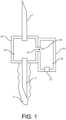
図1は、一部の実施に従う血液サンプル最適化システムを示す。システムは、患者の皮
膚を穿刺してその中の患者の静脈及び静脈内の血液にアクセスするための患者針1を含む
。システムは、再密封可能なブーツ10、ルアー作動弁、又は別の採取インターフェース
又はデバイス内に収容されかつ再密封可能なブーツ10、ルアー作動弁、又は別の採取イ
ンターフェース又はデバイスによって当初は密封されていることができる、サンプル針(
すなわち、バキュテナー(登録商標)などと共に使用するための再密封可能に密封された
針)5をさらに含む。再密封可能なブーツ10は、患者の血液を採取するためのバキュテ
ナー(登録商標)ボトル(図示せず)を用いることによって、サンプル針5のそばに又は
サンプル針5の周りに押し付けることができる。システムは、サンプル針5に通じる低容
量チャンバ30をさらに含むことができるが、ハウジング50によって形成される隔離チ
ャンバ55に通じる穴又は1つ以上の流路45も含む。 FIG. 1 illustrates a blood sample optimization system according to some implementations. The system includes a
The system further includes a resealable boot 10 (i.e., a resealably sealed
隔離チャンバ55は、隔離チャンバ55の容積に応じて、所定の又は測定された量であ
ることができる、患者の血液の最初のアリコートを受け入れかつ保持するためのチャンバ
、流路、通路、ロック、又は他の構造である。最初の採血は、一般的に、後続の採血に比
べて菌血症及び敗血症を引き起こす微生物又は他の病原体を含有しているか又はより含有
の影響を受けやすい。隔離チャンバ55は、硬いハウジング内に収容されるか、ハウジン
グ自体に形成され又はハウジング自体によって画定された容器であることができ、或いは
チューブ又は内腔として実現されることができる。隔離チャンバ55は、どのように形成
されかつ実施されるかにかかわらず、所定の容積を有することができる。一部の実施では
、所定の容積は、患者針の容積に基づくこと、すなわち、患者針の容積よりも少ない容積
から任意の容積から患者針の容積の20倍以上大きい容積までの範囲であることができる
。隔離チャンバ55の所定の容積は、隔離されかつ処分される血液の量を節約又は最小化
するように設定されることもできる。 The
隔離チャンバ55は、チャンバハウジング50内に形成、包含、又は収容されることが
でき、プラスチック、ゴム、鋼、アルミニウム又は他の適切な材料で作られることができ
る。例えば、隔離チャンバ55は、可撓性チューブ又は他のエラストマー材料から形成さ
れることができる。隔離チャンバ55は、空気が隔離チャンバ55から出ることを可能に
する空気透過性血液バリア20をさらに含む。本明細書で使用される「空気透過性血液バ
リア」という用語は、空気透過性だが実質的に血液不透過性の物質、材料又は構造体を意
味する。代表的な例は、疎水性膜及び疎水性コーティング、疎水性膜又は疎水性コーティ
ングと組み合わせた親水性膜又は親水性コーティング、メッシュ、フィルタ、機械的弁、
抗菌性材料、又は隔離チャンバ55が血液で満たされるときに隔離チャンバ55から空気
を追い出すことができる他の任意の手段を含むことができる。様々な例示的な実施形態に
おいて、空気透過性血液バリアは、空気が液体と接触するまで通過することを可能にする
1つ以上の材料によって形成されることができ、このような材料は、空気及び/又は液体
の通過を防止又は阻止するために完全に又は部分的に密封される。言い換えれば、液体と
の接触より前に、材料は空気透過性のバリアを形成している。液体との接触後、材料は、
空気及び/又は液体の更なる通過を実質的に又は完全に防止する。 The
It may include an antimicrobial material, or any other means capable of expelling air from the
The further passage of air and/or liquid is substantially or completely prevented.
穴又は流路45は、任意の所望の長さ、断面形状又はサイズであることができ、かつ/
又は任意の所望の角度又は向きで低容量チャンバ30から離れるように形成されることが
できる。穴又は流路45はまた、最初のアリコートの血液サンプルを隔離チャンバ55内
に保持する一方向フラップ又は一方向弁60を含むことができる。一部の特定の実施では
、穴又は流路45は、低容量チャンバ30から隔離チャンバ55への一方向の血液の流れ
のための「ダックビル」弁又はフラッパ弁60などを含むことができる。空気透過性血液
バリア20は、空気が出ることを可能にするが血液と接触すると密封する材料で構成する
こともでき、それによって外気が隔離チャンバ55に入ることを許容しない。この密封は
弁を不要にする。 The holes or
or away from the
弁60は、任意のタイプの弁又は開閉機構であることができる。チャンバ30は、実質
的に残留血液を保持しないように設計されており、特定の容積又は割合の血液を隔離チャ
ンバ55に保持し又は通過させるように設計することができる。同様に、隔離チャンバ5
5は、抗菌コーティングのような任意のタイプのコーティング、又は隔離された最初の採
血の成分の同定及び/又は診断を支援するコーティングも含むことができる。
5 may also include any type of coating, such as an antimicrobial coating, or a coating that aids in the identification and/or diagnosis of the components of the isolated initial blood draw.
ハウジング50及び40は、アクリロニトリルブタジエンスチレン(ABS)又は他の
熱可塑性材料又はポリマー材料などのプラスチック、ゴム、鋼、又はアルミニウムを含む
任意の適切な材料から形成されることができる。空気透過性血液バリア20は、最初の採
血による血液と接触すると又は空気の追い出しが停止されたときに、又は事象と隔離チャ
ンバ55内の血液との任意の組み合わせの場合に活性化される、色提供物質又は他の信号
伝達機構を含むことができる。空気透過性バリアはまた、外部流体源、しぶき等によるフ
ィルタの不注意による又は早過ぎる密封を阻止又は防止する疎水性膜又はカバーなどの外
層を含むことができる。隔離チャンバ55はまた、チャンバが充填されたことをユーザー
が視覚的に確認することを可能にするために半透明又は透明であることができる。 The
図2は、一部の代替的な実施に従う血液サンプル最適化システムを示す。図2に示す実
施では、隔離チャンバ55又は廃棄チャンバが患者針1を取り囲み、端部が開放されたカ
フ又はハウジングが廃棄チャンバと接続され、サンプル針ハウジングベース及びハウジン
グを取り囲んでいる。患者針1とサンプル針5とは、ブーツ56によって互いと接続され
ており、ブーツ56は、それを貫通する連続的な採血流路を形成している。ブーツ56は
、採血流路から隔離チャンバ55に通じる単一の穴又は流路を含む。デバイスは、他の実
施では、複数の穴又は流路を含むことができる。各穴又は流路は、一方向弁を含むことが
でき、所定の量の血流のために寸法設定されかつ適合されることができる。 FIG. 2 shows a blood sample optimization system according to some alternative implementations. In the implementation shown in FIG. 2, an
隔離チャンバ55は、空気透過性血液バリアを含む。フィルタは、所定容積の血液が隔
離チャンバ55に集められたときに、それぞれ、感知及び/又は指示するためのセンサ又
はインジケータをさらに含むことができる。その指示は、バキュテナー(登録商標)など
の真空採血管又はボトルをサンプル針5に取り付けるようにユーザーに警告する。隔離チ
ャンバ55用のハウジングは、任意のサイズ又は形状であることができ、ハウジング内の
内部空間又は容積を画定するために任意のタイプの材料を含むことができる。内部空間は
、最初は空気のみで満たされているが、汚染除去剤、凝固剤などの薬剤又は物質でコーテ
ィングされることもできる。真空採血管がサンプル針5に取り付けられると、血液は自動
的に患者針1に、採血流路及びサンプル針5を通ってボトルに流入する。サンプル針5は
、採血ボトルがサンプル針に取り付けられていないときにサンプル針を密封する再密封可
能なブーツ、コーティング又は膜によって覆われている。 The
図3は、一部の代替的な実施に従う血液サンプル最適化システムを示す。図示の実施で
は、サンプル針5は、再密封可能なブーツ又は膜によって取り囲まれ、さらに患者針1と
接続される。サンプル針及び患者針を通って血液流路が形成される。サンプル針と患者針
との間の接続は、主血液流路から隔離チャンバ104へと導く流路、ポート又は開口部を
含む「T」又は「Y」コネクタ102を含む。 3 shows a blood sample optimization system according to some alternative implementations. In the implementation shown, a
T又はYコネクタ102は、フラップ又は一方向弁を含み、所定の流量の血液のために
寸法設定されかつ適合された穴を有する。隔離チャンバ104は、チューブから形成され
又は硬いハウジングによって形成されることができ、最初は空気で満たされている。隔離
チャンバ104は、自動的に、すなわち、患者自身の血圧による圧力下で患者から流出す
る血液を受け入れる。隔離チャンバ104は、好ましくは隔離チャンバ104を形成しか
つ近位端がT又はYコネクタ102に接続されたチューブの遠位端に、空気透過性血液バ
リア106を含む。T又はYコネクタ102は、最も効率的な血流のために任意の所望の
角度で分岐することができ、最初のアリコートの血液と主要な採血サンプルとの混合を最
小限に抑え又は排除するために、開口部及び流路と主血液流路との間の接合部分を最小化
するように形成されることができる。 The T or Y connector 102 includes a flap or one-way valve and has a hole sized and adapted for a predetermined flow rate of blood. The isolation chamber 104 can be formed from a tube or formed by a rigid housing and is initially filled with air. The isolation chamber 104 automatically receives blood flowing out of the patient, i.e., under pressure due to the patient's own blood pressure. The isolation chamber 104 preferably includes an air-permeable blood barrier 106 at the distal end of the tube that forms the isolation chamber 104 and is connected at its proximal end to the T or Y connector 102. The T or Y connector 102 can branch at any desired angle for most efficient blood flow and can be formed to minimize the interface between the openings and flow paths and the main blood flow path to minimize or eliminate mixing of the first aliquot of blood with the main blood sample.
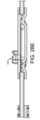
一部の代替的な実施では、サンプル針は、図4に示すように、その反対側の端部がT又
はYコネクタ102と接続している任意の長さのチューブに取り付けられることができる
。隔離チャンバ104は、最初のアリコートに所定量の血液サンプルを含む限り、任意の
形状又は容積であることができる。T又はYコネクタ102はまた、主血液流路に対して
平行な開口部又は流路を含むことができる。空気透過性血液バリアは、所定量の血液が隔
離チャンバに集められたとき、又は放出される空気が特定の閾値、すなわちゼロに達した
ときを示すインジケータ107又は他の機構をさらに含むことができる。チューブはまた
、挟んでチューブを通る流体の流れを防止するのに使用することができるクリップ109
を含むことができる。 In some alternative implementations, the sample needle can be attached to any length of tubing with its opposite end connecting to a T or Y connector 102 as shown in FIG. 4. The isolation chamber 104 can be of any shape or volume so long as it contains a predetermined amount of blood sample in the initial aliquot. The T or Y connector 102 can also include an opening or flow path parallel to the main blood flow path. The air permeable blood barrier can further include an indicator 107 or other mechanism that indicates when a predetermined amount of blood has been collected in the isolation chamber or when the released air reaches a certain threshold, i.e., zero. The tubing can also be fitted with a clip 109 that can be used to pinch and prevent fluid flow through the tubing.
may include.
ひとたび空気透過性血液バリア及び一次チャンバが密封されると、最初のアリコートの
血液が隔離チャンバ104に閉じ込められ、サンプルを得るためにバキュテナー(登録商
標)ボトルのような真空採血管がサンプル針5に取り付けられる。採血管は取り外すこと
ができ、サンプル針5は再密封される。更なる採血又はサンプルのために、任意の数の後
続の採血管を取り付けることができる。全ての採血が完了すると、最初のアリコートの血
液が隔離チャンバ104に閉じ込められたまま、システムを廃棄することができる。 Once the air permeable blood barrier and primary chamber are sealed, the first aliquot of blood is trapped in the isolation chamber 104 and a vacuum blood collection tube, such as a Vacutainer® bottle, is attached to the
図5は、一部の代替的な実施に従う血液サンプル最適化システムを示す。図示の実施で
は、サンプル針5が患者針とチューブによって接続されている。「T」又は「Y」コネク
タ120が、チューブに沿って任意の所望の位置に追加され、実質的に上記のように、隔
離チャンバ204に通じる開口部、ポート又は流路を含む。 5 illustrates a blood sample optimization system according to some alternative implementations. In the implementation shown, a
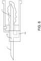
図6は、一次採取流路として形成された隔離チャンバ304が最初のアリコートの血液
を受け入れ、採血流路に隣接して設けられている、一部の代替的な実施に従う血液サンプ
ル最適化システムを示す。隔離チャンバ304は、採血流路、患者針1及び/又はサンプ
ル針5を取り囲むことができる。一次採取流路は、T又はYコネクタ120、又は他のタ
イプの開口部又は流路を含むことができる。隔離チャンバ304は空気透過性血液バリア
を含み、空気透過性血液バリアは、上記のように、血液などの流体が接触したことのイン
ジケータを含むこともできる。 6 illustrates a blood sample optimization system according to some alternative implementations in which an
一部の実施では、患者針1又はサンプル針5のいずれか又は両方をルアーロック雄コネ
クタ又はルアーロック雌コネクタで置き換えることができる。しかしながら、様々な実施
で、血液サンプル最適化システムのサンプル針端部にあるコネクタは、周囲空気圧で加圧
されかつ空気透過性血液バリアの空気出口を含む隔離チャンバへ最初のアリコートの血液
をそらすことを可能にするために最初に密封される。このようにして、システムは受動的
かつ自動的に患者自身の血圧を用いて隔離チャンバの周囲空気圧に打ち勝ち、空気透過性
血液バリアを通して空気を押し出し、隔離チャンバ内の空気を血液に置き換える。 In some implementations, either or both of the
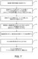
図7は、血液培養の質を最適化するための例示的な方法のフローチャートである。70
2において、臨床医が患者の静脈に針を挿入する。704において、血液が隔離チャンバ
に流れ込み、空気透過性血液バリアを通して隔離チャンバ内の空気を隔離チャンバから押
し出す。一部の実施では、隔離チャンバの容積は、0.1立方センチメートル(cc)未
満から5立方センチメートル(cc)以上である。隔離チャンバは、血液サンプルの第2
部分及び他の後続の部分又は後続の採取よりも汚染しやすい血液サンプルの第1部分を採
取するように寸法設定されかつ適合されている。隔離チャンバは空気透過性血液バリアを
有し、この血液バリアを通して空気を患者の静脈から押し出された血液で追い出すことが
できるので、このような血液は、血液サンプルを受け入れかつ保管するためのバキュテナ
ー(登録商標)又は他のボトルに引き込まれるか又は他の方法で入る前に、必然的にかつ
自動的に隔離チャンバに流入する。 FIG. 7 is a flow chart of an exemplary method for optimizing blood culture quality.
At 702, a clinician inserts a needle into a patient's vein. At 704, blood flows into the isolation chamber, forcing air therein out of the isolation chamber through an air permeable blood barrier. In some implementations, the isolation chamber has a volume of less than 0.1 cubic centimeters (cc) to 5 cubic centimeters (cc) or more. The isolation chamber contains a second portion of the blood sample.
The isolation chamber is sized and adapted to draw a first portion of a blood sample that is more susceptible to contamination than any other subsequent portions or subsequent draws, and the isolation chamber has an air-permeable blood barrier through which air can be displaced with blood forced out of a patient's vein, such blood necessarily and automatically flowing into the isolation chamber before being drawn or otherwise entered into a Vacutainer® or other bottle for receiving and storing the blood sample.
隔離チャンバがいっぱいになると、血液は、血液が通過するのを阻止又は防止する空気
透過性血液バリアに集まるか、さもなければ接触する。706において、血液が空気透過
性血液バリアの全内部表面積と接触すると、空気透過性血液バリアは閉じられ、空気はも
はや流出又は流入しない。708において、臨床医は、バキュテナー(登録商標)などの
真空採血管を取り付けることができることを示すインジケータを提供されるか又は満杯の
チャンバを見ることができる。インジケータは、一次チャンバがいっぱいであるか否かを
確認するための一次チャンバの可視性、例えば、色を変える血液バリア、又は他のインジ
ケータを含むことができる。隔離チャンバの充填時間は、実質的に瞬間的であり得るので
、このようなインジケータは、存在する場合、隔離チャンバが満たされているというだけ
である可能性がある。 When the isolation chamber is full, blood collects or otherwise contacts the air permeable blood barrier which blocks or prevents blood from passing through. At 706, when blood contacts the entire interior surface area of the air permeable blood barrier, the air permeable blood barrier closes and air no longer flows out or in. At 708, the clinician is provided with an indicator that a vacuum blood collection tube, such as a Vacutainer®, can be attached or the clinician can see the full chamber. Indicators can include visibility of the primary chamber to see if the primary chamber is full, for example, a blood barrier that changes color, or other indicator. Since the fill time of the isolation chamber can be substantially instantaneous, such an indicator, if present, can only be that the isolation chamber is full.
真空採血管が取り付けられる前、針、サンプリング流路、及び隔離チャンバの間の連通
は、隔離チャンバの血液バリアの密封によって制限され、従って隔離によって空気がシス
テムに再び入ることを可能にしない。連通経路の密封は、機械的にねじること又は他の動
作、小さな穴又は曲がりくねった経路によって達成され、別個の弁又は機械的な動作又は
臨床医による操作の必要性をなくす。710において、真空採血管を取り外すと、自己密
封式の膜がサンプル針を密封し、712において、更なる後続の真空採血管を取り付ける
ことができる。714において、サンプルが採取されると、デバイスが患者から取り外さ
れ、廃棄される。 Before the evacuated blood collection tube is attached, communication between the needle, sampling flow path, and isolation chamber is limited by the sealing of the blood barrier of the isolation chamber, thus not allowing air to re-enter the system by isolation. Sealing of the communication path is achieved by mechanical twisting or other action, small holes or tortuous paths, eliminating the need for separate valves or mechanical actions or manipulation by the clinician. When the evacuated blood collection tube is removed at 710, a self-sealing membrane seals the sample needle, and at 712, a further subsequent evacuated blood collection tube can be attached. Once the sample has been taken at 714, the device is removed from the patient and discarded.
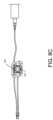
図8A~8Eは、一部の実施に従う、非汚染採血用の例示的な血液サンプル最適化シス
テム800を示す。血液サンプル最適化システム800は、チューブ、患者針(又は両方
)、又は他の血管又は静脈アクセスデバイスに接続されることができる入口ポート802
と、隔離チャンバチューブ806への第1出口とサンプル採取チューブ808への第2出
口とを有する経路スプリッタ804とを含む。隔離チャンバチューブ806及びサンプル
採取チューブ808の一方又は両方は、チューブから形成されることができる。一部の実
施では、隔離チャンバチューブ806は、特定の量の当初血液サンプルを収容するように
寸法設定される。サンプル採取チューブ808は、ひとたび隔離チャンバチューブ806
が満たされると、血液サンプルを受け入れる。サンプル採取チューブ808は、バキュテ
ナー(登録商標)ベース又はハウジング810、又は他の血液サンプル採取デバイスに接
続されることができる。 8A-8E show an exemplary blood
and a
When filled, it receives a blood sample. The
血液隔離システム800は血液隔離デバイス812をさらに含み、血液隔離デバイス8
12は、図8B~8Dにより詳細に示すようにハウジング818を含み、ハウジング81
8は、非汚染サンプル採取チューブ808用の経路を画定するか又はいずれかの端部が非
汚染サンプル採取チューブ808と接続されるサンプリング流路820を含む。サンプリ
ング流路820は、非汚染サンプル採取チューブ808に沿った位置でハウジング818
をより良好に固定しかつ安定させるように、ハウジング818を通って曲線状であること
ができる。 The
12 includes a
The
The
血液隔離デバイス812は、隔離チャンバチューブ806又は他のチャンバと接続され
る隔離チャンバ822をさらに含む。隔離チャンバ822は、空気透過性血液バリア82
4で終端している。空気透過性血液バリア824はまた、血液サンプル(すなわち、非汚
染血液サンプル)の正式な採取を開始することができるインジケータとして、血液との完
全な接触時に異なる色に変わる着色剤を含むことができる。小さい光、音発生機構などの
他のインジケータを使用することができる。一部の実施では、空気透過性血液バリアは、
隔離チャンバ822の方向から直角に配置されているが、ハウジング818に使用される
空間及び材料を節約するために任意の距離又は向きに配置されることができる。ハウジン
グ818及びその内容物は、任意の剛性材料又は半剛性材料又は一連の材料から形成され
ることができる。 The
4. The air
Although positioned perpendicular to the orientation of
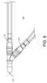
図9は、例えば、図8A~8Eに示すような血液隔離システムに用いる経路スプリッタ
900を示す。経路スプリッタ900は、入口ポート902と、主管路出口ポート904
と、隔離流路出口ポート906とを含む。入口ポート902は、同様に患者針システムに
接続される主チューブに、又は直接患者針に接続されることができる。主管路出口ポート
904は、バキュテナー(登録商標)ベース又はハウジングなどの採血システムへの主管
路チューブに、又は直接そのような採血システムに接続されることができる。隔離流路出
口ポート906は、測定された量又は所定の閾値まで血液の第1サンプルを受け入れかつ
隔離するための隔離チューブに接続されることができる。代わりに、隔離流路出口ポート
906は、隔離チャンバに接続されることができる。隔離流路出口ポート906は、好ま
しくは、主管路出口ポート904から20~70度の角度に曲げられ、一方、主管路出口
ポート904は、好ましくは、入口ポート902と一直線である。本明細書に記載された
機構及び技術に従って、所定の量の最初の血液サンプルが隔離チューブ又は隔離チャンバ
内に隔離されると、後続の血液サンプルは、入口ポート902に流入し、障害物なしで主
管路出口ポート904から直接流出する。 9 illustrates a
and an isolation
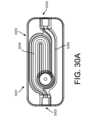
図10A~10Dは、別の実施に従う血液隔離デバイス1000を示す。血液隔離デバ
イス1000は、入口ポート1002と、主出口ポート1004と、隔離流路ポート10
06とを含む。入口ポート1002は、患者針又は関連するチューブと接続されることが
できる。主出口ポート1004は、バキュテナー(登録商標)、関連するチューブ、又は
ルアー作動弁などの血液サンプル採取デバイスに接続されることができる。隔離流路ポー
ト1006は、主出口ポート1004から隔離チャンバ1008へと分離する。一部の実
施では、隔離チャンバ1008は、ハウジング又は他の容器1001内に螺旋流路として
形成される。 10A-10D show a
10.06. The
隔離チャンバ1008は、実質的に上記のように、遠位端が空気透過性血液バリア10
10に接続される。隔離チャンバ1008内の空気は、空気透過性血液バリア1010を
通して、隔離流路ポート1006内に案内される最初のアリコートの血液によって追い出
される。ひとたび隔離チャンバ1008が満たされると、主出口ポート1004を通して
更なる採血を行うことができ、これらのサンプルは汚染されていない。 The
10. Air in the
図11A~11Eは、他の代替的な実施に従う血液隔離デバイス1100を示す。血液
隔離デバイス1100は、上述の入口ポートと同様の入口ポート1102と、主出口ポー
ト1104と、主出口ポート1104及び入口ポート1102から分離する隔離流路ポー
ト1106とを含む。隔離流路ポートは、隔離チャンバ1108に接続されている。図1
1A~11Eに示す実施では、血液隔離デバイスは、隔離チャンバ1108として機能す
る流路を内部に有するベース部材1101を含む。流路は、ベース部材1101を通る曲
がりくねった経路として形成されることができ、一方、ベース部材1101は、患者の四
肢に載るように成形されかつ形成される。 11A-11E show a
In the implementations shown in Figures 1A-11E, the blood isolation device includes a
隔離チャンバ1108の一部は、血液隔離インジケータ1109として機能するように
、空気透過性血液バリア1110に出る直前に、ベース部材から又はベース部材の上面付
近に突出することができる。インジケータ1109は、透明な材料、又は血液と接触する
と変色する材料で形成されることができる。 A portion of the
一部の実施では、血液隔離デバイス1100は、常時閉じている針、バキュテナー(登
録商標)シールド又は他の採取デバイスなどの採血デバイス1120を含むことができる
。採血デバイス1120は、効率及び利便性のために血液隔離デバイス1100と共に製
造及び販売されることができ、それにより患者針の挿入プロセスによって汚染される恐れ
がある最初のアリコートの血液を隔離することができる。従って、採血デバイス1120
は、非汚染血液サンプルを採取して偽陽性の検査のリスクを低減しかつ非汚染サンプルを
確実にすることができる。 In some implementations, the
can draw an uncontaminated blood sample to reduce the risk of a false positive test and ensure an uncontaminated sample.
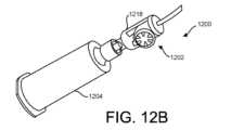
図12A~12Dは、さらに他の代替的な実施に従う血液サンプル最適化システム12
00を示す。システム1200は、バキュテナー(登録商標)又は他の採取及びサンプリ
ングデバイスのような採血デバイス1204に取り付けるための血液隔離デバイス120
2を含む。血液隔離デバイス1202は、バキュテナー(登録商標)容器又はバイアルが
採血デバイス1204の採取針に取り付けられる前に最初のアリコート又は量の血液を受
け入れ、かつその最初のアリコート又は量を血液隔離デバイス1202の隔離流路内に隔
離するように構成されかつ配置されている。 12A-12D show a blood sample optimization system 12 according to yet another alternative implementation.
12. The
2. The
一部の実施では、血液隔離デバイス1202は、入口ポート1212と、主出口ポート
と、隔離流路ポートとを含むことができる。入口ポート1212は、患者針又は関連する
チューブに接続されることができる。主出口ポート1214は、真空採血容器又はバキュ
テナー(登録商標)などの他の採取デバイス、関連するチューブ、ルアーコネクタ、注射
器、ルアー作動弁などとの接続を可能にするために、常時閉じている針又はデバイスに接
続されることができる。隔離流路ポートは、主出口ポートから隔離チャンバ1218へと
分離する。 In some implementations, the
一部の実施では、隔離チャンバ1218は、隔離デバイス1202の本体内の流路とし
て形成される。隔離チャンバ1218は、U字形流路、S字形流路、螺旋流路、又は任意
の他の曲がりくねった流路などの曲がりくねった流路であることができる。隔離デバイス
1202は、ハウジング又は他の収容体と、その中に形成された1つ以上の流路とを含む
ことができる。図12A及び12Bに示すように、隔離デバイス1202は、本体120
6とキャップ1208とを含む。本体1206には1つ以上の空洞又は流路が形成され、
空洞又は流路にはキャップ1208から延びる1つ以上のアーム1210がさらに形成さ
れ、1つ以上のアーム1210は、本体1206の空洞又は流路に隣接して一次採取ポー
ト及び主出口ポートを形成している。 In some implementations, the
6 and a
The cavity or flow passage is further formed with one or
図13A~13Dは、さらに他の代替的な実施に従う血液サンプル最適化システム13
00を示す。システム1300は、バキュテナー(登録商標)などの採血デバイス130
4又は他の体液採取及びサンプリングデバイスに取り付けるための血液隔離デバイス13
02を含む。血液隔離デバイス1302は、バキュテナー(登録商標)容器又はバイアル
が採血デバイス1304の採取針に取り付けられる前に最初のアリコート又は量の血液を
受け入れ、かつその最初のアリコート又は量の血液又は他の体液を血液隔離デバイス13
02の隔離流路内に隔離するように構成されかつ配置されている。 13A-13D show a blood sample optimization system 13 according to yet another alternative implementation.
00. The system 1300 includes a blood collection device 130, such as a Vacutainer®.
4 or other body fluid collection and sampling device for attachment to a blood isolation device 13
The blood isolation device 1302 receives an initial aliquot or volume of blood before a Vacutainer® container or vial is attached to the collection needle of the blood collection device 1304, and transfers that initial aliquot or volume of blood or other bodily fluids to the blood isolation device 1304.
The isolation flow path is constructed and arranged to be isolated within the isolation flow path of .
血液隔離デバイス1302は、入口ポート1314と、主出口ポート1312と、隔離
流路ポート1316とを有するハウジング1301を含む。入口ポート1314は、患者
針又は関連するチューブに接続されることができる。主出口ポート1312は、真空採血
容器又はバキュテナー(登録商標)などの他の採取デバイス、関連するチューブ、ルアー
コネクタ、注射器、ルアー作動弁などとの接続を可能にするために、常時閉じている針又
はデバイスに接続されることができる。隔離流路ポート1316は、主入口ポート131
4から隔離チャンバ1318へと分離する。 The blood isolation device 1302 includes a housing 1301 having an inlet port 1314, a primary outlet port 1312, and an isolated
4 into a
図13A~13Dに示す実施では、隔離チャンバ1318は、ハウジング1301内の
空洞又はチャンバとして形成されるか又はハウジング1301を画定する壁によって形成
される。隔離チャンバ1318は、U字形流路、S字形流路、螺旋流路などの曲がりくね
った流路、又はハウジング1301とキャップ1307との協働及び接続によって画定さ
れる任意の他の曲がりくねった流路であることができ、キャップ1307は、隔離チャン
バ1318内の曲がりくねった流路のための1つ以上の壁又はディレクタを提供する突出
部1305を含むことができる。キャップ1307からの突出部1305は、真っ直ぐで
あるか湾曲していることができ、突出部1305に埋め込まれた様々な流路、開口部又は
溝を有することができ、キャップ1307から任意の角度又は向きで延びることができる
。隔離チャンバ1318の形成を完了するためにキャップ1307がハウジング1301
と接続されると、突出部1305は曲がりくねった流路の少なくとも一部を形成し、隔離
チャンバ1318内に曲がりくねった流路によって形成される隔離流路に最初のアリコー
ト又は量の血液又は他の体液を隔離する。 13A-13D, the
When connected, the protrusions 1305 form at least a portion of a serpentine flow path and isolate an initial aliquot or volume of blood or other bodily fluid in an isolated flow path formed by the serpentine flow path within the
隔離チャンバ1318は、実質的に上記のように空気透過性血液バリア1310を含む
。隔離チャンバ1318内の空気は、患者の血圧によって隔離チャンバ1318内に供給
される最初のアリコートの血液によって空気透過性血液バリア1310を通して追い出さ
れる。隔離チャンバ1318が満たされ、隔離チャンバ1318内の空気が追い出される
と、バキュテナー(登録商標)のような血液サンプル採取デバイスによって提供されるよ
うな真空又は他の圧力のような力が次のアリコート又は量の血液又は体液を引き抜くため
に提供されるまで、患者の血圧は、血液隔離デバイス1302、特に、出口ポート131
2に更なる血液を追い込み又は供給するのには不十分である。主出口ポート1312を通
して更なる採血を行うことができ、あらゆる汚染物質が最初のアリコートの血液と共に隔
離チャンバ1318内に隔離されているので、これらのサンプルは汚染されない。 The
2. Additional blood can be drawn through main exit port 1312 and these samples will not be contaminated because any contaminants have been isolated in
図14A~14Eは、患者の血液サンプルに対して実施される血液培養又は検査におけ
る偽陽性を低減するために最初のアリコート又はサンプルの汚染物質を隔離する採血シス
テム1400のさらに別の実施を示す。採血システム1400は、血液サンプル採取デバ
イス1403と患者針(図示せず)との間に接続されることができる血液隔離デバイス1
401を含む。血液サンプル採取デバイス1403は、バキュテナー(登録商標)などで
あることができる。血液隔離デバイス1401は、血液サンプルへのアクセス及び血液サ
ンプルの採取のために患者の血管系に挿入される患者針と接続されることができる入口ポ
ート1402を含む。入口ポート1402は、同様に患者針と接続されるチューブ又は他
の導管と接続されることもできる。 14A-14E show yet another implementation of a blood collection system 1400 that isolates contaminants from an initial aliquot or sample to reduce false positives in blood cultures or tests performed on a patient's blood sample. The blood collection system 1400 includes a blood isolation device 1403 that can be connected between a blood sample collection device 1403 and a patient needle (not shown).
401. Blood sample collection device 1403 can be a Vacutainer® or the like. Blood isolation device 1401 includes an
入口ポート1402は、血液隔離デバイス1401への開口部を画定し、この開口部は
、患者針と接続されるチューブもしくは他の導管又は患者針自体と同じ断面寸法であるこ
とができる。例えば、開口部は、約0.045インチ(1.143mm)の直径を有する
円形であることができるが、0.01インチ(0.254mm)以下から0.2インチ(
5.08mm)以上の直径を有することができる。血液隔離デバイス1401は、血液隔
離デバイス1401から及び血液サンプル採取デバイス1403への開口部を画定する出
口ポート1404をさらに含む。出口ポート1404は、同様に血液隔離デバイス140
3と接続されるチューブ又は他の導管と接続されることもできる。出口ポート1404は
、チューブなどを含むがそれらに限定されない様々なデバイスの取り付け用の、ねじ付き
キャップ、ルアーコネクタ(雄型又は雌型)、ねじが切られていない締め代又は接着継手
などのコネクタデバイスをさらに含むことができる。 The
The blood isolation device 1401 can have a diameter of 5.08 mm or greater. The blood isolation device 1401 further includes an exit port 1404 that defines an opening from the blood isolation device 1401 and into the blood sample collection device 1403. The exit port 1404 can also be connected to the blood isolation device 1401 via a
3. Outlet port 1404 may also include a connector device, such as a threaded cap, a Luer connector (male or female), an unthreaded interference, or an adhesive joint, for attachment of various devices, including but not limited to, tubing, etc.
血液隔離デバイス1401は、入口ポート1402と出口ポート1404との間にサン
プリング流路1406をさらに含み、サンプリング流路1406は、最初のアリコートの
血液が隔離されると血液サンプル経路として機能する。サンプリング流路1406は、任
意のサイズ、形状又は構成の流路又は導管であることができる。一部の実施では、サンプ
リング流路1406は、入口ポート1402の開口部と実質的に同様の断面積を有する。
他の実施では、サンプリング流路1406は、入口ポート1402から出口ポート140
4まで徐々に広がることができる。 The blood isolation device 1401 further includes a
In another implementation, the
It can be gradually expanded to 4.
血液隔離デバイス1401は隔離チャンバ1408をさらに含み、隔離チャンバ140
8は、入口ポート1402と出口ポート1404との間の任意の位置でサンプリング流路
1406に接続されかつサンプリング流路1406から分離又は方向転換されるが、好ま
しくは入口ポート1402の近くのサンプリング流路1406の近位端に接続されかつ近
位端から分離又は方向転換される。隔離チャンバ1408は、最初は大気圧に維持され、
サンプリング流路1406からの方向転換点と反対側の隔離チャンバ1408の遠位端又
はその近傍に空気出口1412を含む。空気出口1412は、空気透過性血液バリア14
12を含む。図14Bに示すように、空気透過性血液バリア1412は、保護カバー14
16で覆われていることができる。保護カバー1416は、患者自身の血圧によって隔離
チャンバ1408内に強制的に血液が供給されることによって空気が隔離チャンバから追
い出されるときに空気が空気透過性血液バリア1412から出ることを依然として可能に
しながら、ユーザーが彼らの指又は他の外部器具で空気透過性血液バリア1412に触れ
るのを妨げるように寸法設定されかつ構成されることができる。また、保護カバー141
6は、空気透過性血液バリアが周囲の流体又は飛沫に偶発的に曝されるのを阻止又は防止
するように構成されることができる。これは、保護カバーに疎水性膜を追加することを含
むがそれに限定されない、様々な機械的方法で行うことができる。 The blood isolation device 1401 further includes a isolation chamber 1408.
8 may be connected to and separated or redirected from the
The isolation chamber 1408 includes an air outlet 1412 at or near the distal end thereof opposite the redirection point from the
12. As shown in FIG. 14B, the air permeable blood barrier 1412 is
14. The protective cover 1416 can be sized and configured to prevent a user from touching the air-permeable blood barrier 1412 with their fingers or other external instruments, while still allowing air to exit the air-permeable blood barrier 1412 when air is forced out of the isolation chamber by blood being forced into the isolation chamber 1408 by the patient's own blood pressure.
6 can be configured to inhibit or prevent accidental exposure of the air permeable blood barrier to ambient fluids or splashes, this can be accomplished by a variety of mechanical methods including, but not limited to, adding a hydrophobic membrane to the protective cover.
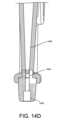
図14C及び14Dに示すように、サンプリング流路1406は、赤血球を溶解する可
能性を最小限に抑えるために、より小さい直径からより大きい直径になる円筒形又は円錐
台形であることができる。同様に、サンプリング流路1406は、赤血球を溶解する可能
性がある急カーブ又は鋭角が最小限の量で又はなしで形成される。サンプリング流路14
06は、迂回経路1409を通して入口ポート1402の近くで隔離チャンバ1408へ
と分離する。迂回経路1409は、任意の断面形状又はサイズを有することができるが、
好ましくは、入口ポート1402の少なくとも一部の断面形状と同様である。 As shown in Figures 14C and 14D, the
14.06 separates near the
Preferably, it is similar to the cross-sectional shape of at least a portion of the
一部の実施では、サンプリング流路1406及び隔離チャンバ1408は、ハウジング
1414に形成された溝、流路、ロック又は他の経路によって形成される。ハウジング1
414は、プラスチック、金属又は他の剛性又は半剛性材料で作られることができる。ハ
ウジング1414は、上部部材と密封可能に嵌合する下部部材を有することができる。下
部部材及び上部部材の一方又は両方は、サンプリング流路1406及び隔離チャンバ14
08、並びに迂回経路1409、入口ポート1402、及び出口ポート1404を含むこ
とができる。一部の他の実施では、迂回経路1409、入口ポート1402、及び/又は
出口ポート1404のうちの1つ以上が、ハウジング1414のいずれかの端部に接続さ
れるキャップ部材によって少なくとも部分的に形成されることができる。一部の実施では
、上部部材及び下部部材、並びにキャップ部材は、レーザー溶接、ヒートシール、接着、
スナップ止め、ねじ止め、ボルト止めなどによって互いに連結されることができる。他の
実施では、迂回経路1409及び/又は隔離チャンバ1408の内面の一部又は全部が、
汚染除去剤、凝固剤などの薬剤又は物質でコーティング又は充填されることができる。例
えば、隔離チャンバ1408が満たされて最初のアリコートの血液が迂回経路1409に
戻るとき、隔離された血液の最後の量が凝固し、隔離チャンバ1408とサンプリング流
路1406との間に障壁を作り出すように、迂回経路1409に凝固剤を提供することが
できる。 In some implementations, the
The housing 1414 can be made of plastic, metal, or other rigid or semi-rigid material. The housing 1414 can have a lower member that sealably mates with an upper member. One or both of the lower and upper members can accommodate the
14.08, as well as a
The
It may be coated or filled with an agent or substance, such as a decontamination agent, a clotting agent, etc. For example, a clotting agent may be provided in the
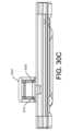
図15A~15Gは、血液隔離デバイス1500を示す。血液隔離デバイス1500は
、真空採血容器又はバキュテナー(登録商標)などの他の採取デバイス、関連するチュー
ブ、ルアーコネクタ、注射器、ルアー作動弁などとの接続を可能にするために常時閉じて
いる針又はデバイスに接続されることができる。 15A-15G show a
血液隔離デバイス1500は、血液サンプルへのアクセス及び血液サンプルの採取のた
めに患者の血管系に挿入される患者針と接続されることができる入口ポート1502を含
む。入口ポート1502は、同様に患者針と接続されるチューブ又は他の導管と接続され
ることもできる。入口ポート1502は、血液隔離デバイス1500への開口部を画定し
、この開口部は、患者針と接続されるチューブもしくは他の導管又は患者針自体と同じ断
面寸法であることができる。例えば、開口部は、約0.045インチ(1.143mm)
の直径を有する円形であることができるが、0.01インチ(0.254mm)以下から
0.2インチ(5.08mm)以上の直径を有することができる。 The
The grooves can be circular with a diameter of 0.01 inches (0.254 mm) or less to 0.2 inches (5.08 mm) or more.
入口ポート1502はまた、ねじ切り又はルアーフィッティングなどのような密封又は
流体密封のコネクタ又は接続部を含むことができる。一部の実施では、患者針に結合され
ているチューブ又は他の導管は、部品同士の共成形、接着、レーザー溶接、又は熱接合な
どによって、入口ポート1502と一体化されることができる。これによって、血液隔離
デバイス1500は、患者針と共に単一ユニットとして製造及び販売され、採血又はサン
プリングの際に患者針を血液隔離デバイス1500に接続する必要性をなくすことができ
る。 The
血液隔離デバイス1500は、血液隔離デバイス1500から及び血液サンプル採取デ
バイスへの開口部を画定する出口ポート1504をさらに含む。出口ポート1504は、
同様に血液隔離デバイスと接続されるチューブ又は他の導管と接続されることもでき、ね
じ切り又はルアーフィッティングなどの密封又は流体密封コネクタ又は接続部を含むこと
ができる。したがって、上記のように、血液隔離デバイス1500は、患者針及び/又は
チューブ及び血液サンプル採取デバイスと共に単一ユニットとして製造及び販売され、採
血又はサンプリングの際に患者針及び血液サンプル採取デバイスを血液隔離デバイス15
00に接続する必要性をなくすことができる。 The
It may also be connected to tubing or other conduits that are connected to the blood isolation device and may include a hermetic or fluid-tight connector or connection, such as a threaded or luer fitting. Thus, as noted above,
This eliminates the need to connect to 00.
血液隔離デバイス1500は、入口ポート1502と出口ポート1504との間にサン
プリング流路1506をさらに含み、サンプリング流路1506は、最初のアリコートの
血液が隔離されると血液サンプル経路として機能する。サンプリング流路1506は、任
意のサイズ、形状、又は構成の流路又は導管であることができる。一部の実施では、サン
プリング流路1506は、入口ポート1502の開口部と実質的に同様の断面積を有する
。他の実施では、サンプリング流路1506は、入口ポート1502から出口ポート15
04まで徐々に広がることができる。 The
It can be gradually expanded to 04.
血液隔離デバイス1500は隔離チャンバ1508をさらに含み、隔離チャンバ150
8は、入口ポート1502と出口ポート1504との間の任意の位置でサンプリング流路
1506に接続されかつサンプリング流路1506から分離又は方向転換されるが、好ま
しくは入口ポート1502の近くのサンプリング流路1506の近位端に接続されかつ近
位端から分離又は方向転換される。一部の実施では、迂回路はY字分岐点を含む。隔離チ
ャンバ1508は、好ましくは大気圧に維持され、隔離チャンバ1508の遠位端又はそ
の近傍に通気口1510を含む。通気口1510は、空気透過性血液バリア1512を含
む。図15Cは、隔離チャンバ1508が患者からの血液の最初のアリコート又はサンプ
ルで満たされた血液隔離デバイス1500を示す。 The
15A is connected to and separated or redirected from the
空気透過性血液バリア1512は、保護カバー1516で覆われていることができる。
保護カバー1516は、患者自身の血圧によって隔離チャンバ1508内に強制的に血液
が供給されることによって空気が隔離チャンバから追い出されるときに空気が空気透過性
血液バリア1512から出ることを依然として可能にしながら、ユーザーが彼らの指又は
他の外部器具で空気透過性血液バリア1512に触れるのを妨げるように寸法設定されか
つ構成されることができる。保護カバー1516は、フィルタが周囲の流体又は飛沫に偶
発的に曝されるのを阻止又は防止するように構成されることができる。これは、保護カバ
ーに疎水性膜を追加することを含むがそれに限定されない、様々な機械的方法で行うこと
ができる。 The air
The
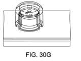
図15Bは、血液隔離デバイス1500の出口ポート1504及び通気口1510を含
むハウジング1501の上面からの血液隔離デバイス1500の斜視図であり、サンプル
採取デバイスが起動される前、サンプリング流路1506が空である間に最初のアリコー
トの血液が隔離チャンバ1508を満たすことを示す。図15Gは、血液隔離デバイス1
500の出口ポート1504及びハウジング1501の底面からの血液隔離デバイス15
00の斜視図であり、サンプル採取デバイスが起動される前、サンプリング流路1506
が空である間に最初のアリコートの血液が隔離チャンバ1508を満たすことを示す。図
15Cは、血液隔離デバイス1500の入口ポート1502及び通気口1510を含むハ
ウジング1501の上面からの血液隔離デバイス1500の別の斜視図であり、隔離され
た血液が実質的に隔離チャンバ1508内にとどまっている間に血液がサンプリング流路
1506を通って採取されることを示す。 15B is a perspective view of the
500
15 is a perspective view of the
15C is another perspective view of the
図15Dは、一部の実施に従う血液隔離デバイス1500の断面図であり、サンプリン
グ流路1506及び隔離チャンバ1508を画定するハウジング1501を示す。図15
E及び15Fは、本明細書に記載される1つ以上の実施に従う血液隔離デバイス用のハウ
ジングの様々なフォームファクタを示す。 15D is a cross-sectional view of a
15E and 15F show various form factors of a housing for a blood isolation device according to one or more implementations described herein.
隔離チャンバ1508は、サンプリング流路1506よりも大きい断面積を有すること
ができ、断面積又は長さは、所定の又は特定の血液量が隔離又はロックされるように構成
されることができる。サンプリング流路1506は、患者針のチューブ又は採血デバイス
のチューブのいずれか又は両方のためのチューブに適合するように寸法設定されることが
できる。 The
ハウジング1501は、複数の部品又は単一の一体部品から形成されることができる。
一部の実施では、図15Dに示すように、ハウジング1501は、互いに嵌合する上部部
材1520と下部部材1522とを含み、それらの一方又は両方は、例えば、射出成形プ
ロセスによって又はエッチング、切削、穿孔などによって予め形成された溝、流路、ロッ
ク、導管又は他の経路を有する。上部部材1520は、レーザー溶接、熱接合、超音波溶
接、接着、ねじ、リベット、ボルトなどを使用することなどの任意の嵌合又は接続機構に
よって、又はラッチ、溝、舌状部、ピン、フランジなどの他の嵌合機構によって、下部部
材1522と接続されることができる。 The
15D, the
図15Dに示すような一部の実施では、上部部材1520は、溝、流路、ロック、導管
又は他の経路を含むことができ、一方、下部部材1522は、上部部材1520の溝、流
路、ロック又は他の経路のうちの少なくとも1つに嵌合するように寸法設定されかつ適合
された突出部1524を含むことができる。突出部1524は、例えば、サンプリング流
路1506及び/又は隔離チャンバ1508のいずれかの形成を完了させるために、部分
的な溝又は部分的な流路などの表面特徴を提供することができる。一部の実施では、突出
部1524は、対応する溝、流路、ロック又は他の経路内によりぴったりと嵌合するため
に、1つ以上の傾斜した側面又は面を形成されることができる。さらに他の実施では、上
部部材1520と下部部材の両方が、溝、流路、ロック又は他の経路、並びに1つ以上の
突出部1524を含むことができる。 15D, the upper member 1520 can include a groove, flow channel, lock, conduit, or other passage, while the
一部の実施では、サンプリング流路1506及び隔離チャンバ1508は、ハウジング
1501に形成された溝、流路、ロック又は他の経路によって形成される。ハウジング1
501は、ゴム、プラスチック、金属又は他の材料を含む任意の適切な材料で作られるこ
とができる。ハウジング1501は、透明もしくは半透明の材料から、又は不透明もしく
は非半透明の材料から形成されることができる。他の実施では、ハウジング1501は、
大部分が不透明又は非透明であることができるが、サンプリング流路1506及び/又は
隔離チャンバ1508に直接隣接するハウジング表面は、透明又は半透明であり、最初に
隔離チャンバ1508が必要な又は所望の程度まで満たされているという視覚的な合図又
はサイン、及び/又は、次に汚染されていない血液サンプルがサンプリング流路1506
を通して採取される間、隔離された血液が隔離されたままであるという視覚的な合図又は
サインを施術者に与える。隔離の他の視覚的な合図又はサインは、以下に限定されるもの
ではないが、血液の接触、浸透、又は部分的な浸透で空気透過性血液バリア1512が異
なる色に変わること、隔離チャンバに沿った又は隔離チャンバに隣接する任意の位置にあ
る色分けされたタブ又はインジケータ、可聴信号、振動信号、又は他の信号を含むことが
できる。 In some implementations, the
While the majority can be opaque or non-transparent, the housing surfaces directly adjacent the
The
患者の皮膚から多数の病原体を集める可能性がある患者の患者針(図示せず)による静
脈穿刺の後、患者自身の血圧が隔離チャンバ1508内の大気圧に打ち勝って空気透過性
血液バリア1512を通して隔離チャンバ1508内の空気を追い出すときに、これらの
病原体を有する患者の血液の最初の量が、血液隔離デバイス1500入口ポート1502
に入り、最も抵抗の少ない経路をたどることによって隔離チャンバ1508に流入する。
患者の血圧は、密封されたサンプリング流路1506内で高まっている空気圧に打ち勝つ
のに十分ではない。最終的に、所定の容積を有する隔離チャンバ1508は、空気透過性
血液バリア1512を通して空気を追い出す血液で満たされる。血液が空気透過性血液バ
リアに衝突すると、血液は空気透過性血液バリア1512の材料と相互作用して、通気口
1510を完全に又は部分的に密封する。施術者がいまやバキュテナー(登録商標)カプ
セル又は他の血液サンプル採取デバイスを利用してサンプリングのために患者の血液の次
の量を得ることができるという信号又は表示が提供されることができる。隔離チャンバ1
508内の血液は、このとき隔離チャンバ内で事実上隔離されている。 Following venipuncture with a patient's needle (not shown), which may collect a number of pathogens from the patient's skin, an initial volume of the patient's blood carrying these pathogens enters the
and flows into the
The patient's blood pressure is not sufficient to overcome the air pressure building up in the sealed
The blood in 508 is now effectively isolated in the isolation chamber.
血液隔離経路1508を満たした後、バキュテナー(登録商標)又は他の血液サンプル
採取デバイスの使用より前に、患者の血圧は、サンプリング流路1506内の空気の圧縮
を引き起こし、場合によっては少量の血液が隔離チャンバ1508への方向転換点を過ぎ
てサンプリング流路1506に移動し、サンプリング流路1506を通して採取される汚
染されていない血液を待ち行列に入れる。 After filling the
場合によっては、図15Hに示すように、入口ポート1532は、取り外し可能な患者
針に接続するための雄型ルアーコネクタを含むことができ、出口ポート11534は、注
射器と接続するための雌型ルアーコネクタを含むことができる。入口ポート及び出口ポー
トのこの実施は、バキュテナー(登録商標)型デバイスの患者の静脈をつぶす傾向を回避
するために、本明細書に記載の任意のデバイスと共に使用されることができる。この実施
では、臨床医は、調整された方法で注射器を使用して血液サンプルを採取することができ
る。動作中、注射器は出口ポート1004に取り付けられ、針は入口ポート1002に取
り付けられる。静脈穿刺は、針を用いて、臨床医が注射器を引っ張ることなく行われる。
血液の最初のアリコートが隔離チャンバを満たし、その後、注射器を使用して、隔離チャ
ンバ内に隔離された血液を迂回して、採取流路を通して血液のサンプルを採取することが
できる。 In some cases, as shown in FIG. 15H, the inlet port 1532 can include a male luer connector for connecting to a removable patient needle, and the outlet port 11534 can include a female luer connector for connecting to a syringe. This implementation of the inlet and outlet ports can be used with any device described herein to avoid the tendency of Vacutainer type devices to collapse the patient's vein. In this implementation, the clinician can draw a blood sample using a syringe in a coordinated manner. In operation, the syringe is attached to the
An initial aliquot of blood fills the isolation chamber, after which a syringe can be used to withdraw a sample of blood through the withdrawal flow path, bypassing the blood isolated within the isolation chamber.
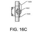
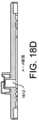
図16~19は、血液隔離デバイスのさらに別の実施を示す。図16A~16Dは、バ
キュテナー(登録商標)(図示せず)のような真空採血容器などの血液サンプル採取デバ
イスと患者針(図示せず)及び/又は関連するチューブとの間に接続されることができる
血液隔離デバイス1600を示す。図17は、血液隔離デバイスの下部部材を示し、図1
8は、血液隔離デバイスの上部部材を示し、上部部材及び下部部材は、以下でより詳しく
説明するように、相互に嵌合して、入口ポート、出口ポート、隔離チャンバ及びサンプリ
ング流路を形成することができる。図19A及び19Bは、互いに嵌合する上部部材及び
下部部材を示す。図16~19は本明細書に記載される血液隔離デバイスを構成する1つ
の例示的な方法を示しており、他の形態の構成も可能であることを理解されたい。 Figures 16-19 show yet another implementation of a blood isolation device. Figures 16A-16D show a blood isolation device 1600 that can be connected between a blood sample collection device, such as an evacuated blood collection container like a Vacutainer® (not shown), and a patient needle (not shown) and/or associated tubing. Figure 17 shows the lower member of the blood isolation device, and Figure 1
FIG. 8 illustrates a top member of a blood isolation device, which top and bottom members can mate with each other to form inlet ports, outlet ports, isolation chambers, and sampling channels, as described in more detail below. FIGs. 19A and 19B illustrate top and bottom members that mate with each other. It should be understood that FIGs. 16-19 illustrate one exemplary method of constructing the blood isolation devices described herein, and that other configurations are possible.
図16A~16Dを参照すると、血液隔離デバイス1600は、血液サンプルへのアク
セス及び血液サンプルの採取のために患者の血管系に挿入される患者針と接続されること
ができる入口ポート1602を含む。入口ポート1602は、同様に患者針と接続される
チューブ又は他の導管と接続されることもできる。入口ポート1602は、血液隔離デバ
イス1600への開口部を画定し、この開口部は、患者針と接続されるチューブもしくは
他の導管又は患者針自体と同じ断面寸法であることができる。例えば、開口部は、約0.
045インチ(1.143mm)の直径を有する円形であることができるが、0.01イ
ンチ(0.254mm)以下から0.2インチ(5.08mm)以上の直径を有すること
ができる。 16A-16D, blood isolation device 1600 includes an
The circular shape may be 0.045 inches (1.143 mm) in diameter, but may have a diameter of 0.01 inches (0.254 mm) or less to 0.2 inches (5.08 mm) or more.
入口ポート1602はまた、ねじ切り又はルアーフィッティングなどのような密封又は
流体密封コネクタ又は接続部を含むことができる。一部の実施では、患者針に結合されて
いるチューブ又は他の導管は、部品同士の共成形、接着、レーザー溶接、又は熱接合など
によって、入口ポート1602と一体化されることができる。これによって、血液隔離デ
バイス1600は、患者針及び/又はチューブと共に単一ユニットとして製造及び販売さ
れ、採血又はサンプリングの際に患者針を血液隔離デバイス1600に接続する必要性を
なくすことができる。 The
血液隔離デバイス1600は、血液隔離デバイス1600から及び血液サンプル採取デ
バイスへの開口部を画定する出口ポート1604をさらに含む。出口ポート1604は、
同様に血液隔離デバイスと接続されるチューブ又は他の導管と接続されることもでき、ね
じ切り又はルアーフィッティングなどの密封又は流体密封コネクタ又は接続部を含むこと
もできる。したがって、上記のように、血液隔離デバイス1600は、患者針及び/又は
チューブ及び血液サンプル採取デバイスと共に単一ユニットとして製造及び販売され、採
血又はサンプリングの際に患者針及び血液サンプル採取デバイスを血液隔離デバイス16
00に接続する必要性をなくすことができる。 The blood isolation device 1600 further includes an
It may also be connected to tubing or other conduits that are connected to the blood isolation device, and may include a hermetic or fluid-tight connector or connection, such as a threaded or luer fitting. Thus, as noted above, blood isolation device 1600 may be manufactured and sold as a single unit along with a patient needle and/or tubing and a blood sample collection device, and the patient needle and blood sample collection device may be connected to blood isolation device 1600 during blood collection or sampling.
This eliminates the need to connect to 00.
血液隔離デバイス1600は、入口ポート1602と出口ポート1604との間のサン
プリング流路1606と、入口ポート1602と出口ポート1604との間の任意の位置
でサンプリング流路1606に接続されかつサンプリング流路1606から分離又は方向
転換される隔離チャンバ1608とをさらに含む。サンプリング流路1606は、ひとた
び最初のアリコートの血液が隔離チャンバ1608内に隔離されると、採血経路として機
能する。サンプリング流路1606は、任意のサイズ、形状又は構成の流路又は導管であ
ることができる。一部の実施では、サンプリング流路1606は、入口ポート1602の
開口部と実質的に同様の断面積を有する。他の実施では、サンプリング流路1606は、
入口ポート1602から出口ポート1604まで徐々に広がることができる。隔離チャン
バ1608は、図17及び19により詳しく示すように、血液がサンプリング流路160
6のより小さい直径に入るのに対して、まずリザーバに入ろうとするように、隔離流路の
経路に向かって大きいリザーバを形成するべくより大きい断面を有することができる。 The blood isolation device 1600 further includes a
The
6 may have a larger cross section to form a larger reservoir towards the path of the isolation channel so that it first tries to enter the reservoir versus entering the smaller diameter of 6.
一部の例示的な実施では、サンプリング流路1606と隔離チャンバ1608との間の
方向転換は、ダイバータ分岐点1607によるものである。ダイバータ分岐点1607は
、実質的にY字形、T字形、又はU字形であることができる。一部の好ましい例示的な実
施では、図17A~17Bに示すように、ダイバータ分岐点1607は、入口ポート16
02からの流れが優先的に隔離チャンバ1608に向けられるように構成される。隔離チ
ャンバ1608は、最初の血液流を隔離チャンバ1608の方へ及び隔離チャンバ160
8内に向けるための湾曲部又は傾斜路を含むか又は形成することもできる。 In some exemplary implementations, the change of direction between the
16.02 is configured to preferentially direct blood flow toward
8. The
隔離チャンバ1608は、好ましくは大気圧に維持され、隔離チャンバ1608の遠位
端又はその近傍に通気口1610を含む。通気口1610は、上記のように空気透過性血
液バリア1612を含むことができる。 The
血液隔離デバイス1600は、複数の部品又は単一の一体部品から形成されることがで
きるハウジング1601を含むことができる。一部の実施では、図17A~17E及び図
18A~18Fに示すように、ハウジング1601は、互いに嵌合する上部部材1620
と下部部材1622とを含む。血液隔離デバイス1600は、上部部材1620が下部部
材1622に機械的に取り付けられたときに、両者の間の接合部分がガスケット又は密封
部材によって密封されるように、ガスケット又は他の密封部材(図示せず)を含むことも
できる。図17A~17Eは、血液隔離デバイス1600用のハウジングの下部部材16
22を示す。下部部材1622は、サンプリング流路1606、隔離チャンバ1608、
及びダイバータ分岐点1607を形成するために、射出成形プロセスによって又はエッチ
ング、切削、穿孔などによって下部部材1622に予め形成された溝、流路、ロック、導
管又は他の経路を含むことができる。 The blood isolation device 1600 can include a
and a
22. The
and may include grooves, channels, locks, conduits or other pathways preformed in the
隔離チャンバ1608は、血液がサンプリング流路1606のより小さい直径に入るの
に対して、まず隔離チャンバ内に優先的に移動するように、サンプリング流路1606よ
りも大きい断面を有することができる。 The
図18A~18Fは、レーザー溶接、熱接合、接着、ねじ、リベット、ボルトなどを使
用することなどの任意の嵌合又は接続機構によって、又はラッチ、溝、舌状部、ピン、フ
ランジなどの他の嵌合機構によって、下部部材1622と接続可能な上部部材1620を
示す。上部部材1620は、サンプリング流路1606、隔離チャンバ1608、及びダ
イバータ分岐点1607を形成するために、溝、流路、ロック、導管又は他の経路の一部
又はすべてを含むことができる。さらに他の実施では、上部部材1620と下部部材16
22の両方が、溝、流路、ロック又は他の経路を含むことができる。 18A-18F show an
Both of the grooves, channels, locks, or other pathways may be included.
一部の実施では、サンプリング流路1606及び隔離チャンバ1608は、ハウジング
1601に形成された溝、流路、ロック又は他の経路によって形成される。ハウジング1
601は、ゴム、プラスチック、金属又は任意の他の適切な材料で作られることができる
。ハウジング1601は、透明もしくは半透明の材料から、又は不透明もしくは非半透明
の材料から形成されることができる。他の実施では、ハウジング1601は、大部分が不
透明又は非半透明であることができるが、サンプリング流路1606及び/又は隔離チャ
ンバ1608に直接隣接するハウジング表面は、透明又は半透明であることができ、最初
に隔離チャンバ1608が必要な又は所望の程度まで満たされているという視覚的な合図
又はサイン、及び/又は、次に汚染されていない血液サンプルがサンプリング流路160
6を通して採取される間、隔離された血液が隔離されたままであるという視覚的な合図又
はサインを施術者に与える。隔離の他の視覚的な合図又はサインは、以下に限定されるも
のではないが、血液の接触、浸透、又は部分的な浸透で空気透過性血液バリア1612が
異なる色に変わること、隔離チャンバに沿った又は隔離チャンバに隣接する任意の位置に
ある色分けされたタブ又はインジケータ、可聴信号、振動信号、又は他の信号を含むこと
ができる。 In some implementations, the
16.
The
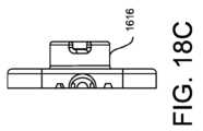
図18A~18Fに示すように、空気透過性血液バリア1612は、保護部材1616
で覆われているか又は保護部材1616によって包囲されていることができる。保護部材
1616は、空気が隔離チャンバ1608から追い出されるときに空気が空気透過性血液
バリア1612から出ることを依然として可能にしながら、ユーザーが彼らの指又は他の
外部器具で空気透過性血液バリア1612に触れるのを妨げるように寸法設定されかつ構
成されることができる。一部の実施では、保護部材1616は、上部部材1620の上面
から上に空気透過性血液バリア1612の周りに延びる突出部を含む。保護部材1616
は、フィルタが周囲の流体又は飛沫に偶発的に曝されるのを阻止又は防止するように構成
されることができる。これは、保護カバーに疎水性膜を追加することを含むがそれに限定
されない、様々な機械的方法で行うことができる。 As shown in FIGS. 18A-18F, the air
The
The protective cover can be configured to inhibit or prevent accidental exposure of the filter to ambient fluids or splashes, which can be accomplished by a variety of mechanical methods, including but not limited to adding a hydrophobic membrane to the protective cover.
使用時、血液隔離デバイス1600は、サンプリング流路1606と隔離チャンバ16
08とを含む。両方の経路が最初は大気圧の空気で満たされているが、サンプリング流路
1606は、バキュテナー(登録商標)又は他のこのような密封された採血デバイスによ
って最初は密封されている出口ポート1604に向けられ、隔離チャンバ1608は、空
気透過性血液バリア1612を含む大気への通気口1610で終端している。 In use, the blood isolation device 1600 includes a
08. While both pathways are initially filled with air at atmospheric pressure, the
患者の皮膚から多数の病原体を集める可能性がある患者針(図示せず)による静脈穿刺
の後、これらの病原体を有する患者の血液の最初の量が、血液隔離デバイス1600の入
口ポート1602を通過する。この汚染されている可能性のある血液の最初の量は、最も
抵抗の少ない経路を見出すことによって、隔離チャンバ1608に優先的に流入する。患
者自身の血圧は、通気口付きの隔離チャンバ1608内の大気圧に打ち勝ち、空気透過性
血液バリア1612を通して隔離チャンバ1608内の空気を追い出すが、密封されたサ
ンプリング流路1606内で高まっている空気圧に打ち勝つには不十分である。様々な例
示的な実施形態では、隔離チャンバ1608及びサンプリング流路1606は、患者の血
圧によって生じた力が、血液隔離デバイスの向きに関わらず、重力の影響に打ち勝つのに
十分であるように構成されることができる。 Following venipuncture with a patient needle (not shown), which may collect numerous pathogens from the patient's skin, an initial volume of the patient's blood carrying these pathogens passes through the
最終的に、隔離チャンバ1608は、空気透過性血液バリア1612を通して空気を追
い出す血液で満たされる。ひとたび血液が空気透過性血液バリアと接触すると、血液は空
気透過性血液バリア1612の材料と相互作用して通気口1610を完全に又は部分的に
密封する。施術者がいまやバキュテナー(登録商標)又は他の採血デバイスを利用するこ
とができるという信号又は表示を提供することができる。 Eventually, the
血液隔離経路1608を満たした後、バキュテナー(登録商標)又は他の血液サンプル
採取デバイスの使用より前に、患者の血圧は、サンプリング流路1606内の空気の圧縮
を引き起こし、場合によっては少量の血液が方向転換点を過ぎてサンプリング流路160
6に移動し、サンプリング流路1606を通して採取される汚染されていない血液を待ち
行列に入れる。 After filling the
6 to queue uncontaminated blood to be collected through
図19Aは、血液隔離デバイス1600の側面図であり、図19Bは、血液隔離デバイ
ス1600の断面図であり、下部部材1622と嵌合する上部部材1620を示す。 19A is a side view of blood isolation device 1600 and FIG. 19B is a cross-sectional view of blood isolation device 1600 showing
図20は、患者の血流への血管アクセスのための患者針2002と、1つ以上の血液サ
ンプルの採取を容易にする血液サンプル採取デバイス2004と、患者針2002と血液
サンプル採取デバイス2004との間の流体接続を提供する導管2006とを含む血液サ
ンプル最適化システム2000を示す。一部の実施では、血液サンプル採取デバイス20
04は、密封された真空容器がその上に配置される密封された採取針を含む保護シールド
を含み、真空容器はひとたび採取針によって穿孔されると、患者針2002から導管20
06を通して真空圧力又は真空力で血液サンプルを吸い込む。 20 illustrates a blood
2004 includes a protective shield containing a sealed collection needle on which a sealed evacuated container is placed, the evacuated container, once pierced by the collection needle, passes through a
The blood sample is drawn through 06 using vacuum pressure or force.
血液サンプル最適化システム2000は、本明細書で説明するように、患者針2002
と血液サンプル採取デバイス2004との間の導管2006上の任意の点に位置する血液
隔離デバイス2008をさらに含む。 The blood
and the blood
図21は、ウィッキング材料チャンバを使用する通気口付きでない血液隔離デバイス2
100を示す。血液隔離デバイス2100は、ウィッキング材料で満たされた隔離チャン
バ2102によって少なくとも部分的に囲まれ又は隣接されるサンプリング流路2104
を有するハウジング2101を含む。最初のアリコートの血液が患者針からサンプリング
流路2104に引き込まれ、サンプリング流路2104において隔離チャンバ2102の
ウィッキング材料の中に直ちに逃がされる。ウィッキング材料及び/又は隔離チャンバ2
102は、後続の又はそれ以降の採血がウィッキング材料を通り過ぎ、サンプリング流路
2104を通って直接バキュテナー(登録商標)などのサンプリングデバイスに流れるよ
うに、所定量の血液を受け入れかつ保持するように寸法設定されかつ適合されている。ウ
ィッキング材料は、固化剤、汚染除去剤、又は他の添加剤などの物質を含むことができる
。 FIG. 21 illustrates a non-vented blood isolation device 2 using a wicking material chamber.
100. The
The blood sample includes a
102 is sized and adapted to receive and hold a predetermined volume of blood such that subsequent or subsequent blood draws will flow past the wicking material and through the
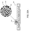
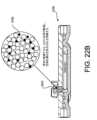
本明細書に記載されるように、空気透過性血液バリアは、多種多様な異なる構造及び材
料を用いて作られることができる。図22A及び22Bに示すように、血液隔離デバイス
2200の空気透過性血液バリア2202は、少なくとも一部のビーズが親水性になるよ
うに処理されたポリマービーズマトリックス2204を含むことができる。空気透過性血
液バリア2202は、カルボキシメチルセルロース(CMC)又はセルロースガムなどの
自己密封材料2206、又は他の密封材料をさらに含む。空気透過性血液バリア2202
は、血液などの流体との接触前又は部分接触中の空気の流れを可能にする空隙2208を
さらに含むことができる。図22Bに示すように、流体と接触すると、自己密封材料22
06が膨張して空隙2208を閉鎖し、空隙2208を通る空気の流れを閉塞し、完全に
又は部分的に密封する。 As described herein, the air permeable blood barrier can be made using a wide variety of different structures and materials. As shown in Figures 22A and 22B, the air
The self-sealing material 22 may further include a
06 expands to close
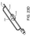
図23A及び23Bは、患者針と接続するための入口ポート2302と、血液サンプル
採取デバイスと接続するための出口ポート2304と、隔離チャンバ2306と、隔離す
るべき汚染されている可能性のある血液の最初のアリコートまで隔離チャンバが満たされ
ると隔離チャンバ2306を迂回するサンプリング流路2308とを有する血液隔離デバ
イス2300のさらに別の実施を示している。隔離チャンバ2306は、入口ポート23
02から最も遠い隔離チャンバ2306の遠位端に疎水性プラグ2312を含む。バキュ
テナー(登録商標)などからのような、出口ポート2304から加えられる真空力又は他
の吸引力は、血液を入口ポート2302内に、そして隔離チャンバ2306内に直接吸い
込み、そこで最初のアリコートの血液が疎水性プラグ2312に接触し、最初のアリコー
トの血液を隔離チャンバ2306に戻して隔離チャンバ2306に隔離する。少量の血液
が、最初は弁2308によって閉鎖されているサンプリング流路2308に入ることがで
きる。弁2308が解放されると、真空の更なる力又は他の力の下で、後続の量の血液が
入口ポート2302に流れ、隔離チャンバ2306を迂回し、サンプリング流路2308
を通り抜けて出口ポート2304に向かって流れ、採取デバイスに送られる。 23A and 23B show yet another implementation of a
2302 includes a
2304 to the collection device.
サンプリング流路2308は、任意の適切な幾何学的形状を有することができ、プラス
チックチューブ又は任意の他の適切な材料から形成されることができる。弁2308は、
最初のアリコートの血液が隔離チャンバ2306内に隔離される前にサンプリング流路を
挟み、脇へそらし、曲げ、又は他の方法で閉じるためにクリップ又は他の封入デバイスで
あることができる。例えば、弁2308は、サンプリング流路2308内のフラップ、ド
ア又は閉鎖可能な窓又は障壁として形成されることもできる。 The
It can be a clip or other encapsulating device to pinch, divert, bend, or otherwise close the sampling flow path before the initial aliquot of blood is isolated in the
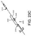
図23C~23Eは、血液隔離デバイス2300’の代替的な実施を示しており、血液
隔離デバイス2300’において、隔離チャンバ2320は、患者針と接続するための入
口ポート2316とバキュテナー(登録商標)、注射器などの血液サンプル採取デバイス
と接続する出口ポート2318との間で主採取流路2322から分岐している。隔離チャ
ンバ2320は、例えば、材料の疎水性プラグ、又は1つ以上の層で形成されたフィルタ
などの空気透過性で血液不透過性の血液バリア2324を含む。弁2324が採取流路2
322を開閉し、デバイス2300’を上記と同様に使用することができる。 23C-23E show an alternative implementation of a blood isolation device 2300' in which an
322 can be opened and closed and device 2300' can be used in the same manner as described above.
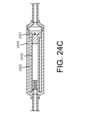
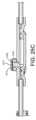
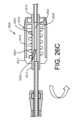
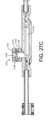
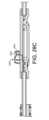
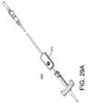
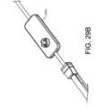
図24A~24Dは、患者の血流への血管アクセスのための患者針2402と、血液検
査又は血液培養のための1つ以上の血液サンプルの採取を容易にする血液サンプル採取デ
バイス2404と、患者針2402と血液サンプル採取デバイス2404との間の流体接
続を提供する導管2406とを含む血液サンプル最適化システム2400を示す。一部の
実施では、血液サンプル採取デバイス2404は、密封された真空容器がその上に配置さ
れる密封された採取針を含む保護シールドを含み、真空容器はひとたび採取針によって穿
孔されると、患者針2402から導管2006を通して真空圧力又は真空力で血液サンプ
ルを吸い込む。 24A-24D show a blood
血液サンプル最適化システム2400は、患者針2402と血液サンプル採取デバイス
2404との間の導管2406上の任意の点に位置する血液隔離デバイス2408をさら
に含む。血液隔離デバイス2408の位置は、血液隔離デバイス2408と患者針240
2との間の導管の長さ、及びその長さが提供する関連する容積に基づくことができる。 The blood
2 and the associated volume that that length provides.
血液隔離デバイス2408は、患者針2402の方を向いて導管2406に接続される
入口ポート2412と、血液サンプル採取デバイス2404の方を向いて導管2406に
接続される出口ポート2414と、ハウジング2416とを含む。ハウジング2416は
、図24A~24Dには実質的に円筒形であるように示されているが、任意の形状である
ことができ、ハウジング2416の両端に位置するように示されているが、ハウジングの
どこにでも位置することができる入口ポート2412と出口ポート2414とを含む。 The
血液隔離デバイス2408は、入口ポート2412と接続される血液隔離チャンバ24
18をさらに含む。血液隔離チャンバ2418は、内側チャンバハウジング2419によ
って画定され、内側チャンバハウジング2419は、最初のアリコートの血液を受け入れ
て隔離する第1の位置から、血液が内側チャンバハウジング2419の周りで内側チャン
バハウジング2419の外側表面とハウジング2416の内側表面とによって画定される
血液サンプル流路2422を通って迂回しかつ/又は流れることを可能にするために内部
チャンバハウジング2419の近位端にある1つ以上の開口部2424を露出させる第2
の位置まで移動可能である。血液隔離チャンバ2418は、血液隔離チャンバ2418の
遠位端に空気透過性血液バリア2420を含む。 The
The
The
動作中、1つ以上の開口部2424が閉じられ、血液隔離チャンバ2418が患者針か
らの直接経路にあるように、内部チャンバハウジング2419は入口ポート2412に向
かう第1の位置にある。患者の静脈穿刺、及び注射器もしくはバキュテナー(登録商標)
又は他の採血デバイス2404による採血の際に、最初のアリコートの血液は血液隔離チ
ャンバ2418に流れ込む。最初のアリコートの血液が血液隔離チャンバに流れ込むと、
血液は血液隔離チャンバ内の空気に取って代わり、最終的に血液は血液バリア2420に
接触し、内側チャンバハウジングを第2の位置に押しやる。内側チャンバハウジング24
19及び/又はハウジング2416は、血液隔離チャンバ2418が満たされ、ロック機
構に打ち勝つ力をもたらし、内側チャンバハウジング2419の第2の位置への移動を可
能にするまで、内側チャンバハウジング2419を第1の位置に維持するために、1つ以
上の小さなタブ、溝、戻り止め、隆起部、隆起線などのロック機構を含むことができる。
ひとたび第2の位置になると、最初のアリコートの血液は血液隔離チャンバ2418に隔
離され、1つ以上の開口部2424が開かれて、血液隔離チャンバ2418を迂回しかつ
/又は血液隔離チャンバ2418の周りを流れる入口ポート2412から採血流路242
2への経路を生じる。 In operation, the one or
During blood collection by
The blood displaces the air in the blood isolation chamber, and eventually the blood contacts the
19 and/or the
Once in the second position, the first aliquot of blood is isolated in the
This results in a route to 2.
上記のように、ハウジング2416及び/又は内側チャンバハウジング2419は、円
筒形及び同心円として形成されることができるが、正方形、長方形、楕円形、長円形、又
は他の断面形状などの任意の形状であることができる。内側チャンバハウジング2419
の遠位端の外面は、それらの間に間隙を有する1つ以上の外向きに突出するタング(突起
部)2421を有することができる。タング2421は、ハウジング2416の内面に接
触して、それらの間に採血流路2422を画定するのを助け、そして内側チャンバハウジ
ング2419を第2の位置に停止させるのを助ける。タング2421間の間隙は、血液が
採血流路2422を通って出口ポート2414に流れることを可能にする。内側チャンバ
ハウジング2419が第2の位置にあり、血液隔離チャンバ2418が血液の第1のアリ
コートで満たされているとき、さらなる血液サンプルが、入口ポート2412を通って、
1つ以上の開口部2424を通って、採血流路を通って、タング2421間の間隙を通っ
て、最終的に出口ポート2414を通って自動的に流れ、採血デバイス2404によって
集められる。 As described above, the
The outer surface of the distal end of the
The blood automatically flows through one or
図25A~25Dは、実質的に図15、16、17、18及び19に記載したように形
成されるが、ユーザー又は他の物体が血液隔離チャンバ2520からの空気抜き機構に触
れ又は空気抜き機構を塞ぐのを阻止するように形成される、血液最適化システム2500
及び血液隔離デバイス2502を示す。最初に血液隔離チャンバ2520内の空気が、患
者の血圧が血液隔離チャンバ2520内の周囲空気圧に打ち勝つ静脈穿刺の際に最初のア
リコートの血液によって追い出される。空気抜き機構は、空気が逃げることを可能にする
が血液が血液隔離チャンバ2520から出るのを阻止する多孔質材料又は材料のセットな
どの空気透過性血液バリア2506を含む。 25A-25D illustrate a
and
空気抜き機構は、空気透過性血液バリア2506を少なくとも部分的に囲むか又は取り
囲む内壁2516と、内壁2516から離間した外壁2504とを含む。外壁2504は
、外壁2504内に形成された1つ以上の空気孔2514を有することができる。外壁2
504は、キャップ、プラグ、カバーなどのような蓋2510を外壁2504に取り付け
、内壁2516の頂部からわずかな距離だけ移動させることができるように、内壁251
6よりも上方に高く延びている。シリコンウエハー又は他のエラストマー材料の形態のシ
ール2508が、外壁2504内に嵌合して空気透過性血液バリア2506を覆い、内壁
2516の頂部に当接する。シール2508は、空気透過性血液バリア2506を覆って
密封し、空気が空気透過性血液バリア2506を通って血液隔離チャンバ2520に入る
のを阻止する。蓋2510の下側の支点2512が、シール2508が血液隔離チャンバ
2520から押し出された空気によって押されたときに内壁2516の頂部から柔軟に外
れることを可能にし、空気が外壁2504の1つ以上の空気孔2514を通って空気透過
性血液バリア2506から出ることを可能にする。 The air venting mechanism includes an
504 is connected to the
6. A
図26A~26Eは、患者の血流への血管アクセスのための患者針2602と、血液検
査又は血液培養のための1つ以上の血液サンプルの採取を容易にする血液サンプル採取デ
バイス2604と、患者針2602と血液サンプル採取デバイス2604との間の流体接
続を提供する導管2606とを含む血液サンプル最適化システム2600を示す。導管2
606は可撓性チューブを含むことができる。好ましい実施では、血液サンプル採取デバ
イス2604は、密封された真空容器がその上に配置される密封された採取針を含む保護
シールド2605を含み、真空容器はひとたび採取針によって穿孔されると、患者針26
02から導管2006を通して真空圧力又は真空力で血液サンプルを吸い込む。 26A-26E show a blood
606 may include a flexible tube. In a preferred implementation, the blood
2002 through
血液サンプル最適化システム2600は、患者針2602と血液サンプル採取デバイス
2604との間の導管2606上の任意の点に位置する血液隔離デバイス2608をさら
に含む。血液隔離デバイス2608の位置は、血液隔離デバイス2608と患者針260
2との間の導管の長さ、及びその長さが提供する関連する容積に基づくことができる。 The blood
2 and the associated volume that that length provides.
血液隔離デバイス2608は、患者針2602の方を向いて導管2606に接続される
入口ポート2612と、血液サンプル採取デバイス2604の方を向いて導管2606に
接続される出口ポート2614とを含む。血液隔離デバイス2608は、いずれも円筒形
であり、同心円状に接続されている、外側ハウジング2616及び内側ハウジング261
7を含む。外側ハウジング2616は、外壁2618と、採血流路2622を画定する内
側導管2620とを含み、導管2606を通して採血デバイス2604に血液を運ぶ。内
側ハウジング2617は、外側ハウジングの内側導管2620と外壁2618との間にぴ
ったりと嵌まり、外側ハウジング2616に対して回転可能である。外側ハウジング26
16と内側ハウジング2617との間の嵌合は、ハウジングを特定の位置に維持する摩擦
嵌めであることができる。内側ハウジング2617は、血液隔離チャンバ2624、好ま
しくは外側ハウジング2616の内側導管2620の外側表面の周りのらせん形又は旋回
形の流路を画定し、図26Eに示すように、空気透過性血液バリアを有する空気孔262
8で終端している。 The
The
26E, the fit between the
It ends with 8.
血液隔離チャンバ2624は、図26Cに示すように、血液隔離デバイスが第1の状態
にあるとき、内側導管2620に形成された迂回路分岐点2624を介して採血流路26
22と接続されている。採取針2604上の保護シールド2606は空気又は血液用の障
害物を提供し、患者の血圧が血液隔離チャネル2624内の周囲空気圧に打ち勝って血液
隔離チャネル2624から空気孔2628を通して空気を追い出すときに、最初のアリコ
ートの血液を血液隔離チャンバ2624へ向けることを可能にする。 The
22. A
図26Dに示されるように、内側ハウジング2617を外側ハウジング2616に対し
て又はその逆に第2の状態へ回転させると、血液隔離チャンバ2624は迂回路分岐点2
624から遮断され、採血流路2622によって、患者針から導管2606を通って採取
針2604までの直接経路が可能になる。外側ハウジング2616及び/又は内側ハウジ
ング2617は、第1の状態から第2の状態への相対回転を容易にするために、それらの
表面の一部に形成された隆起線又は溝を含むことができる。 As shown in FIG. 26D, when the
624, and the blood
図27A~27Dは、実質的に少なくとも図15、16、17、18、19及び25を
参照して説明したように形成されるが、ユーザー又は他の物体が血液隔離チャンバ272
0からの空気抜き機構に触れ又は空気抜き機構を塞ぐのを阻止するように形成される、血
液最適化システム2700及び血液隔離デバイス2702を示す。最初に血液隔離チャン
バ2720内の空気が、患者の血圧が血液隔離チャンバ2720内の周囲空気圧に打ち勝
つ静脈穿刺の際に最初のアリコートの血液によって追い出される。空気抜き機構は、空気
が逃げることを可能にするが血液が血液隔離チャンバ2720から出るのを阻止する多孔
質材料又は材料のセットなどの空気透過性血液バリア2706を含む。 27A-27D are configured substantially as described with reference to at least FIGS. 15, 16, 17, 18, 19 and 25, but in which a user or other object has inserted into blood isolation chamber 272.
2 shows a
空気抜き機構は、空気透過性血液バリア2706を少なくとも部分的に囲むか又は取り
囲む内壁2716と、内壁2716から離間した外壁2704とを含む。キャップ272
2が、好ましくは空気抜き機構の内壁2716と外壁2704との間に嵌合し、内壁27
16又は外壁2704又はそれらの両方に摩擦接触する下部キャップ壁2728を有する
ことによって、空気抜き機構に配置される。キャップ2722は、下方に延びるプラグ2
726の周りでキャップ2722の上面を通って延びる、1つ以上の通気孔2724又は
スリット、開口部、穴などをさらに含む。プラグ2726は、内壁2716によって画定
された空間内にぴったりと嵌まるように寸法設定されかつ適合されている。 The air venting mechanism includes an
2 preferably fits between the
The cap 2722 is positioned on the air vent mechanism by having a
726. The cap 2722 further includes one or
図27Cに示すように、第1の位置において、キャップ2722は、血液隔離チャンバ
2720からの空気が空気透過性血液バリア2706を通って及び1つ以上の通気孔27
24を通って出ることを可能にするために空気抜き機構から延ばされている。ひとたび血
液隔離チャンバ2720からの空気が追い出されると、すなわち、血液隔離チャンバ27
20が患者からの潜在的に汚染された血液の最初のアリコートで満たされると、キャップ
2722は、図27Dに示すように、第2の位置において空気抜き機構上に押し下げられ
ることができ、その結果、プラグ2726は、空気透過性血液バリア2706上の内壁2
716内に嵌合し、空気抜き機構を密閉する。第1の位置又は第2の位置のいずれにおい
ても、キャップ2722は、空気透過性血液バリア2706を外気から又はユーザーが触
れないように保護する。 As shown in FIG. 27C, in the first position, the cap 2722 allows air from the blood isolation chamber 2720 to pass through the air permeable blood barrier 2706 and through one or more air vents 2708.
24. Once the air from the blood isolation chamber 2720 has been purged, i.e., the blood isolation chamber 27
Once the
716 and seals the air venting mechanism. In either the first or second position, cap 2722 protects air permeable blood barrier 2706 from the atmosphere or from contact by the user.
図28A~28Fは、実質的に少なくとも図15、16、17、18、19、25及び
26を参照して説明したように形成されるが、多層フィルタと、一部の実施では、空気透
過性血液バリア用の閉じ込められた反応物質を有するフィルタとを利用する、血液最適化
システム2800及び血液隔離デバイス2802を示す。図28C及び28Dに示すよう
に、空気透過性血液バリア2803は、空気が両方の層を通過できるようにしながら血液
をはじくために、空気透過性だが血液不透過性の材料の第1の層2804と、疎水性材料
などの反応物質を含む第2の層2806とを含む。図28E及び28Fに示すように、空
気透過性血液バリア2803は、第1の層2804と同じ空気透過性だが血液不透過性の
材料から形成される第3の層2808などの任意の数の層を含むことができ、一方、第2
の層2806は、閉じ込められ又は埋め込まれた血液反応物質を含む。 Figures 28A-28F show a
図29A~29Cは、実質的に少なくとも図15、16、17、18、19、25及び
26を参照して説明したように形成されるが、血液隔離チャンバ 2904が少なくとも
部分的に血液吸収材料2906で満たされている、血液最適化システム2900及び血液
隔離デバイス2902を示す。血液吸収材料2906は、患者の静脈穿刺の際に及びバキ
ュテナー(登録商標)又は注射器などの採血デバイスを使用する前に、隔離される血液を
さらに吸い込むためのウィッキング材料として働くことができる。 29A-29C show a
図30A~30Gは、実質的に少なくとも図15、16、17、18、19、25及び
26を参照して説明したように形成される、血液最適化システム3000及び血液隔離デ
バイス3002を示す。血液隔離デバイス3000は、血液サンプルへのアクセス及び血
液サンプルの取り出しのために患者の血管系に挿入される患者針と接続されることができ
る入口ポート3002を含む。入口ポート3002は、同様に患者針と接続されるチュー
ブ又は他の導管と接続されることもできる。入口ポート3002は、血液隔離デバイス3
000への開口部を画定し、この開口部は、患者針と接続されるチューブもしくは他の導
管又は患者針自体と同じ断面寸法であることができる。例えば、開口部は、約0.045
インチ(1.143mm)の直径を有する円形であることができるが、0.01インチ(
0.254mm)以下から0.2インチ(5.08mm)以上の直径を有することができ
る。 30A-30G show a blood optimization system 3000 and a
The needle defines an opening to the patient needle 100, which may be of the same cross-sectional dimensions as the tubing or other conduit that is connected to the patient needle or the patient needle itself. For example, the opening may be of about 0.045
The diameter of the hole may be 0.01 inch (1.143 mm) or less.
The diameter can range from 0.2 inches (5.08 mm) or less to 0.2 inches (5.08 mm) or more.
入口ポート3002はまた、ねじ切り又はルアーフィッティングなどのような、密封又
は流体密封コネクタ又は接続部を含み得る。一部の実施では、患者針に結合されているチ
ューブ又は他の導管は、部品同士の共成形、接着、レーザー溶接、又は熱接合などによっ
て、入口ポート3002と一体化されることができる。これによって、血液隔離デバイス
3000は、患者針及び/又はチューブと共に単一ユニットとして製造及び販売され、採
血又はサンプリングの際に患者針を血液隔離デバイス3000に接続する必要性をなくす
ことができる。 The
血液隔離デバイス3000は、血液隔離デバイス3000から及び血液サンプル採取デ
バイスへの開口部を画定する出口ポート3004をさらに含む。出口ポート3004は、
同様に血液隔離デバイスと接続されるチューブ又は他の導管と接続されることもでき、ね
じ切り又はルアーフィッティングなどの密封又は流体密封コネクタ又は接続部を含むこと
ができる。したがって、上記のように、血液隔離デバイス3000は、患者針及び/又は
チューブ及び血液サンプル採取デバイスと共に単一ユニットとして製造及び販売され、採
血又はサンプリングの際に患者針及び血液サンプル採取デバイスを血液隔離デバイス30
00に接続する必要性をなくすことができる。 The blood isolation device 3000 further includes an
It may also be connected to tubing or other conduits that are connected to the blood isolation device and may include a hermetic or fluid-tight connector or connection, such as a threaded or luer fitting, etc. Thus, as noted above, the blood isolation device 3000 may be manufactured and sold as a single unit along with a patient needle and/or tubing and a blood sample collection device, and the patient needle and blood sample collection device may be connected to the blood isolation device 3000 during blood collection or sampling.
This eliminates the need to connect to 00.
血液隔離デバイス3000は、入口ポート3002と出口ポート3004との間のサン
プリング流路3006と、入口ポート3002と出口ポート3004との間の任意の位置
でサンプリング流路3006に接続されかつサンプリング流路3006から分離又は方向
転換される隔離チャンバ3008とをさらに含む。サンプリング流路3006は、ひとた
び最初のアリコートの血液が隔離チャンバ3008内に隔離されると、採血経路として機
能する。サンプリング流路3006は、任意のサイズ、形状又は構成の流路又は導管であ
ることができる。一部の実施では、サンプリング流路3006は、入口ポート1402の
開口部と実質的に同様の断面積を有する。他の実施では、サンプリング流路3006は、
入口ポート3002から出口ポート3004まで徐々に広がることができる。隔離チャン
バ3008は、血液がサンプリング流路3006のより小さい直径に入るのに対して、ま
ずリザーバに入ろうとするように、隔離流路の経路に向かって大きいリザーバを形成する
べくより大きい断面を有することができる。 The blood isolation device 3000 further includes a
It can widen gradually from the
一部の例示的な実施では、サンプリング流路3006と隔離チャンバ3008との間の
方向転換は、ダイバータ分岐点3007によるものである。ダイバータ分岐点3007は
、実質的にY字形、T字形、又はU字形であることができる。一部の好ましい例示的な実
施では、図17A~17Bに示すように、ダイバータ分岐点3007は、入口ポート30
02からの流れが優先的に隔離チャンバ3008に向けられるように構成される。隔離チ
ャンバ3008は、最初の血液流を隔離チャンバ3008の方へ及び隔離チャンバ300
8内に向けるための湾曲部又は傾斜路を含むか又は形成することもできる。 In some exemplary implementations, the change of direction between the
3002 is configured to preferentially direct blood flow from the
8. The
隔離チャンバ3008は、好ましくは大気圧に維持され、隔離チャンバ3008の遠位
端又はその近傍に通気口3010を含む。通気口3010は、上記のように空気透過性血
液バリア3012を含むことができる。 The
血液隔離デバイス3000は、複数の部品又は単一の一体部品から形成されることがで
きるハウジング3001を含むことができる。一部の実施では、図30Fに示すように、
ハウジング3001は、互いに嵌合する上部部材3020と下部部材3022とを含む。
血液隔離デバイス3000は、上部部材3020が下部部材3022に機械的に取り付け
られたときに、両者の間の接合部分がガスケット又は密封部材によって密封されるように
、ガスケット又は他の密封部材(図示せず)を含むこともできる。下部部材3022は、
サンプリング流路3006、隔離チャンバ3008、及びダイバータ分岐点3007を形
成するために、射出成形プロセスによって又はエッチング、切削、穿孔などによって下部
部材3022に予め形成された溝、流路、ロック、導管又は他の経路を含むことができる
。 The blood isolation device 3000 can include a
The
The blood isolation device 3000 may also include a gasket or other sealing member (not shown) such that when the upper member 3020 is mechanically attached to the lower member 3022, the interface therebetween is sealed by the gasket or sealing member.
The
隔離チャンバ3008は、血液がサンプリング流路3006のより小さい直径に入るの
に対して、まず隔離チャンバ内に優先的に移動するように、サンプリング流路3006よ
りも大きい断面を有することができる。 The
一部の実施では、サンプリング流路3006及び隔離チャンバ3008は、ハウジング
3001に形成された溝、流路、ロック又は他の経路によって形成される。ハウジング3
001は、ゴム、プラスチック、金属又は任意の他の適切な材料で作られることができる
。ハウジング3001は、透明もしくは半透明の材料から、又は不透明もしくは非半透明
の材料から形成されることができる。他の実施では、ハウジング3001は、大部分が不
透明又は非半透明であることができるが、サンプリング流路3006及び/又は隔離チャ
ンバ3008に直接隣接するハウジング表面は、透明又は半透明であることができ、最初
に隔離チャンバ3008が必要な又は所望の程度まで満たされているという視覚的な合図
又はサイン、及び/又は、次に汚染されていない血液サンプルがサンプリング流路300
6を通して採取される間、隔離された血液が隔離されたままであるという視覚的な合図又
はサインを施術者に与える。隔離の他の視覚的な合図又はサインは、以下に限定されるも
のではないが、血液の接触、浸透、又は部分的な浸透で空気透過性血液バリア3012が
異なる色に変わること、隔離チャンバに沿った又は隔離チャンバに隣接する任意の位置に
ある色分けされたタブ又はインジケータ、可聴信号、振動信号、又は他の信号を含むこと
ができる。 In some implementations, the
The
空気透過性血液バリア3012は、キャップ3032で覆われるか又はキャップ303
2によって囲まれることができる。キャップ3032は、空気が隔離チャンバ3008か
ら追い出されるときに空気が空気透過性血液バリア3012から出ることを依然として可
能にしながら、ユーザーが彼らの指又は他の外部器具で空気透過性血液バリア3012に
触れるのを妨げるように寸法設定されかつ構成されることができる。キャップ3032は
、フィルタが周囲の流体又は飛沫に偶発的に曝されるのを阻止又は防止するように構成さ
れることができる。これは、保護カバーに疎水性膜を追加することを含むがそれに限定さ
れない、様々な機械的方法で行うことができる。 The air
2. The
空気抜き機構は、空気透過性血液バリア3012を少なくとも部分的に囲むか又は取り
囲む壁3030を含む。壁3030は、壁3030内に形成された1つ以上の空気孔を有
することができる。キャップ3032は壁3030を覆い、スナップ留め、接着、又は他
の方法で所定の位置に取り付けることができる。シリコンウエハー又は他のエラストマー
材料の形態のシール3017が、壁3030内に嵌合して空気透過性血液バリア3012
を覆い、壁3030の頂部に当接する。シール3017は、空気透過性血液バリア301
2を覆って密封し、空気が空気透過性血液バリア3012を通って血液隔離チャンバ30
08に入るのを阻止する。キャップ3032の下側の支点3012が、シール3008が
血液隔離チャンバ3008から押し出された空気によって押されたときに内壁3016の
頂部から柔軟に外れることを可能にし、空気が壁3030及び/又はキャップ3032内
の1つ以上の空気孔を通って空気透過性血液バリア3012から出ることを可能にする。 The air venting mechanism includes a
The seal 3017 covers the air permeable blood barrier 301 and abuts the top of the
2 and seals it to allow air to pass through the air
08. A
使用時、血液隔離デバイス3000は、サンプリング流路3006と隔離チャンバ30
08とを含む。両方の経路が最初は大気圧の空気で満たされているが、サンプリング流路
3006は、バキュテナー(登録商標)又は他のこのような密封された採血デバイスによ
って最初は密封されている出口ポート3004に向けられ、隔離チャンバ3008は、空
気透過性血液バリア3012を含む大気への通気口3010で終端している。 In use, the blood isolation device 3000 includes a
3008. While both pathways are initially filled with air at atmospheric pressure, the
患者の皮膚から多数の病原体を集める可能性がある患者針(図示せず)による静脈穿刺
の後、これらの病原体を有する患者の血液の最初の量が、血液隔離デバイス3000の入
口ポート3002を通過する。この汚染されている可能性のある血液の最初の量は、最も
抵抗の少ない経路を見出すことによって、隔離チャンバ3008に優先的に流入する。患
者自身の血圧は、通気口付きの隔離チャンバ3008内の大気圧に打ち勝ち、空気透過性
血液バリア3012を通して隔離チャンバ3008内の空気を追い出すが、密封されたサ
ンプリング流路3006内で高まっている空気圧に打ち勝つには不十分である。様々な例
示的な実施形態では、隔離チャンバ3008及びサンプリング流路3006は、患者の血
圧によって生じた力が、血液隔離デバイスの向きに関わらず、重力の影響に打ち勝つのに
十分であるように構成されることができる。 Following venipuncture with a patient needle (not shown), which may collect numerous pathogens from the patient's skin, an initial volume of the patient's blood carrying these pathogens passes through the
最終的に、隔離チャンバ3008は、空気透過性血液バリア3012を通して空気を追
い出す血液で満たされる。ひとたび血液が空気透過性血液バリアと接触すると、血液は空
気透過性血液バリア3012の材料と相互作用して通気口3010を完全に又は部分的に
密封する。施術者がいまやバキュテナー(登録商標)又は他の採血デバイスを利用するこ
とができるという信号又は表示を提供することができる。 Eventually, the
血液隔離経路3008を満たした後、バキュテナー(登録商標)又は他の血液サンプル
採取デバイスの使用より前に、患者の血圧は、サンプリング流路3006内の空気の圧縮
を引き起こし、場合によっては少量の血液が方向転換点を過ぎてサンプリング流路300
6に移動し、サンプリング流路3006を通して採取される汚染されていない血液を待ち
行列に入れる。 After filling the
6 and queues uncontaminated blood to be collected through
さらに別の態様では、本明細書に記載の実施のいずれかの血液隔離チャンバ及び/又は
採血流路又は他のコンポーネントは、視覚的に識別可能な警告を提供するか、又は患者の
血管内への静脈内カテーテル用の導入器のフラッシュ室との動作可能な流体連通に適した
コンポーネントをもたらし得る。デバイス及び方法は、患者からの血液が連通した血漿に
反応する検査コンポーネントと連通して視覚的に変化したときに視覚的に識別可能な警告
を提供する。血液又は血漿との反応は、血液の内容物、物質、又はその閾値の高レベルも
しくは低レベルについて試験するように構成され、結果に応じて外観が視覚的に変化する
ように構成された、血液又は血漿内に配置される1つ以上の試薬に応じて発生する。 In yet another aspect, the blood isolation chamber and/or blood draw flow path or other components of any of the implementations described herein may provide a visually identifiable alert or provide a component suitable for operable fluid communication with a flash chamber of an introducer for an intravenous catheter into a patient's vein. The devices and methods provide a visually identifiable alert when blood from a patient is in communication with a plasma-responsive testing component that changes visually. The reaction with the blood or plasma occurs in response to one or more reagents disposed within the blood or plasma that are configured to test for high or low levels of blood contents, substances, or thresholds thereof, and to visually change appearance depending on the result.
さらに他の態様では、血液隔離チャンバ及び/又は採血流路は、隔離プロセス及び/又
はサンプリングプロセス中に、血液の特定の体積流量を提供するように寸法設定されかつ
適合されることができる。 In yet another aspect, the blood isolation chamber and/or blood collection flow path can be sized and adapted to provide a particular volumetric flow rate of blood during the isolation and/or sampling process.
様々な実施形態を上記で詳細に説明してきたが、他の変更も可能である。他の実施形態
は、添付の特許請求の範囲内に含まれ得る。 Although various embodiments have been described in detail above, other modifications are possible and may fall within the scope of the following claims.
Claims (20)
Translated fromJapanese入口ポートと、
出口ポートと、
分岐点を介して前記入口ポートと接続された隔離チャンバと、
前記分岐点を介して前記入口ポートと接続された近位端と、前記出口ポートと接続され
た遠位端とを有するサンプリング流路と
を含み、
前記隔離チャンバは空気透過性血液バリアを含む通気口を有し、
前記通気口は前記空気透過性血液バリアを少なくとも部分的に囲みかつ1つ以上の空気
孔を含む外壁によって画定され、
前記通気口は、前記外壁を少なくとも部分的に覆うキャップと、空気が前記隔離チャン
バに入るのを阻止する前記空気透過性の血液バリアに隣接する一方向シールとをさらに含
み、
前記隔離チャンバ、前記サンプリング流路及び前記分岐点は、血液の第1の部分が前記
隔離チャンバ内への隔離のために前記空気透過性血液バリアに向かって前記隔離チャンバ
に流れ込み、血液の第2の部分が前記隔離チャンバ及び前記隔離チャンバ内に隔離された
血液の第1の部分を迂回し、前記出口ポートに向かって前記サンプリング流路に導かれる
ように寸法設定されかつ構成される、血液隔離デバイス。 1. A blood isolation device comprising:
An inlet port;
An outlet port;
a separation chamber connected to the inlet port via a branch point;
a sampling channel having a proximal end connected to the inlet port via the branch point and a distal end connected to the outlet port;
the isolation chamber having a vent that includes an air permeable blood barrier;
the vent is defined by an exterior wall at least partially surrounding the air permeable blood barrier and including one or more air holes;
the vent further includes a cap at least partially covering the exterior wall and a one-way seal adjacent the air permeable blood barrier that prevents air from entering the isolation chamber;
a blood isolation device, the isolation chamber, the sampling flow path, and the branch point sized and configured such that a first portion of blood flows into the isolation chamber toward the air permeable blood barrier for isolation within the isolation chamber, and a second portion of blood bypasses the isolation chamber and the first portion of blood isolated within the isolation chamber and is directed to the sampling flow path toward the exit port.
容し画定するハウジングをさらに含む、請求項1に記載の血液隔離デバイス。 10. The blood isolation device of claim 1, further comprising a housing that contains and defines the inlet port, the outlet port, the isolation chamber, and the sampling flow path.
、請求項1に記載の血液隔離デバイス。 10. The blood isolation device of claim 1, wherein the vent further comprises an inner wall within the outer wall that contains the air permeable blood barrier.
記載の血液隔離デバイス。 The blood isolation device of claim 1 , wherein the one-way seal is disposed within the outer wall over an inner wall of the vent.
前記キャップの内面は支点を含み、空気が前記隔離チャンバから漏れ出ること可能にす
るために、前記支点に対して前記シールを前記空気透過性血液バリアから柔軟に開封する
ことができる、請求項4に記載の血液隔離デバイス。 the cap includes an interior surface facing the air permeable blood barrier;
5. The blood isolation device of claim 4, wherein an inner surface of the cap includes a fulcrum against which the seal can be flexibly opened from the air permeable blood barrier to allow air to escape from the isolation chamber.
、請求項1に記載の血液隔離デバイス。 10. The blood isolation device of claim 1, wherein the air permeable blood barrier comprises a sealing material that seals the vent upon contact with blood.
ィルタの第2の層は血液をはじくための疎水性材料を有する、請求項1に記載の血液隔離
デバイス。 10. The blood isolation device of claim 1, wherein the air permeable blood barrier includes a filter having a first layer and a second layer, the second layer of the filter having a hydrophobic material for repelling blood.
近位端に患者針を、遠位端にサンプル採取デバイスを有する採血経路と、
前記採血経路の近位端と遠位端との間で前記採血経路に取り付けられた血液隔離デバイ
スと
を含み、
前記血液隔離デバイスは、
前記患者針の方を向いて前記採血経路と連結された入口ポートと、
前記サンプル採取デバイスの方を向いて前記採血経路と連結された出口ポートと、
分岐点を介して前記入口ポートと接続された隔離チャンバと、
前記分岐点を介して前記入口ポートと接続された近位端と、前記出口ポートと接続され
た遠位端とを有するサンプリング流路と
を含み、
前記隔離チャンバは空気透過性血液バリアを含む通気口を有し、
前記通気口は前記空気透過性血液バリアを少なくとも部分的に囲みかつ1つ以上の空気
孔を含む外壁によって画定され、
前記通気口は、前記外壁を少なくとも部分的に覆うキャップと、空気が前記隔離チャン
バに入るのを阻止する前記空気透過性血液バリアに隣接する一方向シールとをさらに含み
、
前記隔離チャンバ、前記サンプリング流路及び前記分岐点は、血液の第1の部分が前記
隔離チャンバ内への隔離のために前記空気透過性血液バリアに向かって前記隔離チャンバ
に流れ込み、血液の第2の部分が前記隔離チャンバ及び前記隔離チャンバ内に隔離された
血液の第1の部分を迂回し、前記出口ポートに向かって前記サンプリング流路に導かれる
ように寸法設定されかつ構成される、血液隔離及びサンプリングシステム。 1. A blood isolation and sampling system comprising:
a blood collection pathway having a patient needle at a proximal end and a sample collection device at a distal end;
a blood isolation device attached to the blood collection pathway between a proximal end and a distal end of the blood collection pathway;
The blood isolation device comprises:
an inlet port facing the patient needle and connected to the blood collection line;
an outlet port facing the sample collection device and connected to the blood collection pathway;
a separation chamber connected to the inlet port via a branch point;
a sampling channel having a proximal end connected to the inlet port via the branch point and a distal end connected to the outlet port;
the isolation chamber having a vent that includes an air permeable blood barrier;
the vent is defined by an exterior wall at least partially surrounding the air permeable blood barrier and including one or more air holes;
the vent further includes a cap at least partially covering the exterior wall and a one-way seal adjacent the air permeable blood barrier that prevents air from entering the isolation chamber;
1. A blood isolation and sampling system, wherein the isolation chamber, the sampling flow path, and the branch point are sized and configured such that a first portion of blood flows into the isolation chamber toward the air permeable blood barrier for isolation within the isolation chamber, and a second portion of blood bypasses the isolation chamber and the first portion of blood isolated within the isolation chamber and is directed to the sampling flow path toward the exit port.
前記サンプリング流路を収容し画定するハウジングをさらに含む、請求項8に記載の血液
隔離システム。 9. The blood isolation system of claim 8, wherein the blood isolation device further comprises a housing that contains and defines the inlet port, the outlet port, the isolation chamber, and the sampling flow path.
む内壁をさらに含む、請求項8に記載の血液隔離システム。 9. The blood isolation system of claim 8, wherein the vent of the blood isolation device further comprises an inner wall within the outer wall that contains the air permeable blood barrier.
求項8に記載の血液隔離システム。 9. The blood isolation system of claim 8, wherein the one-way seal of the vent is disposed within the outer wall over an inner wall of the vent.
前記キャップの内面は支点を含み、空気が前記隔離チャンバから漏れ出ること可能にす
るために、前記支点に対して前記シールを前記空気透過性血液バリアから柔軟に開封する
ことができる、請求項11に記載の血液隔離システム。 the cap includes an interior surface facing the air permeable blood barrier;
12. The blood isolation system of claim 11, wherein an inner surface of the cap includes a fulcrum against which the seal can be flexibly opened from the air permeable blood barrier to allow air to escape from the isolation chamber.
する封止材料を含む、請求項8に記載の血液隔離システム。 10. The blood isolation system of claim 8, wherein the air permeable blood barrier of the blood isolation device comprises a sealing material that seals the vent upon contact with blood.
ルタを含み、前記フィルタの第2の層は、血液をはじくための疎水性材料を有する、請求
項8に記載の血液隔離システム。 10. The blood isolation system of claim 8, wherein the air permeable blood barrier of the blood isolation device includes a filter having a first layer and a second layer, the second layer of the filter having a hydrophobic material for repelling blood.
入口ポートと、
出口ポートと、
分岐点を介して前記入口ポートと接続された隔離チャンバと、
前記分岐点を介して前記入口ポートと接続された近位端と、前記出口ポートと接続され
た遠位端とを有するサンプリング流路と
を含み、
前記隔離チャンバは空気透過性血液バリアを含む通気口を有し、
前記通気口は前記空気透過性血液バリアを少なくとも部分的に囲みかつ1つ以上の空気
孔を含む外壁によって画定され、
前記通気口は、前記外壁を少なくとも部分的に覆うキャップと、空気が前記隔離チャン
バに入るのを阻止する前記空気透過性血液バリアと隣接する一方向シールとをさらに含み
、
前記隔離チャンバ、前記サンプリング流路及び前記分岐点は、血液の第1の部分が前記
隔離チャンバに流れ込んで前記隔離チャンバを満たし、前記通気口を通して前記隔離チャ
ンバ内の空気を追い出すように、及び、血液の第2の部分が前記隔離チャンバ及び前記隔
離チャンバ内に隔離された血液の第1の部分を迂回し、前記出口ポートに向かって前記サ
ンプリング流路に導かれるように寸法設定されかつ構成される、血液隔離デバイス。 1. A blood isolation device comprising:
An inlet port;
An outlet port;
a separation chamber connected to the inlet port via a branch point;
a sampling channel having a proximal end connected to the inlet port via the branch point and a distal end connected to the outlet port;
the isolation chamber having a vent that includes an air permeable blood barrier;
the vent is defined by an exterior wall at least partially surrounding the air permeable blood barrier and including one or more air holes;
the vent further includes a cap at least partially covering the exterior wall and a one-way seal adjacent the air permeable blood barrier that prevents air from entering the isolation chamber;
a blood isolation device, wherein the isolation chamber, the sampling flow path, and the branch point are sized and configured such that a first portion of blood flows into the isolation chamber to fill the isolation chamber and expel air within the isolation chamber through the vent, and a second portion of blood bypasses the isolation chamber and the first portion of blood isolated within the isolation chamber and is directed to the sampling flow path toward the exit port.
容し画定するハウジングをさらに含む、請求項15に記載の血液隔離デバイス。 16. The blood isolation device of claim 15, further comprising a housing that contains and defines the inlet port, the outlet port, the isolation chamber, and the sampling flow path.
、請求項15に記載の血液隔離デバイス。 16. The blood isolation device of claim 15, wherein the vent further comprises an inner wall within the outer wall that contains the air permeable blood barrier.
に記載の血液隔離デバイス。 16. The one-way seal of claim 15, wherein the one-way seal is disposed within the outer wall over an inner wall of the vent.
2. The blood isolation device according to claim 1 .
前記キャップの内面は支点を含み、空気が前記隔離チャンバから漏れ出ること可能にす
るために、前記支点に対して前記シールを前記空気透過性血液バリアから柔軟に開封する
ことができる、請求項18に記載の血液隔離デバイス。 the cap includes an interior surface facing the air permeable blood barrier;
20. The blood isolation device of claim 18, wherein an inner surface of the cap includes a fulcrum against which the seal can be flexibly opened from the air permeable blood barrier to allow air to escape from the isolation chamber.
、請求項15に記載の血液隔離デバイス。 16. The blood isolation device of claim 15, wherein the air permeable blood barrier comprises a sealing material that seals the vent upon contact with blood.
Applications Claiming Priority (6)
| Application Number | Priority Date | Filing Date | Title |
|---|---|---|---|
| US201662439426P | 2016-12-27 | 2016-12-27 | |
| US62/439,426 | 2016-12-27 | ||
| PCT/US2017/068569WO2018125929A1 (en) | 2016-12-27 | 2017-12-27 | Blood sample optimization system and blood contaminant sequestration device and method |
| JP2019534792AJP7003139B2 (en) | 2016-12-27 | 2017-12-27 | Blood isolation device and blood isolation and sampling system |
| JP2021214177AJP7336821B2 (en) | 2016-12-27 | 2021-12-28 | Fluid diversion device and fluid diversion sampling system |
| JP2023133585AJP7530490B2 (en) | 2016-12-27 | 2023-08-18 | BLOOD SAMPLE OPTIMIZATION SYSTEM AND BLOOD CONTAMINANT ISOLATION DEVICE AND METHOD - Patent application |
Related Parent Applications (1)
| Application Number | Title | Priority Date | Filing Date |
|---|---|---|---|
| JP2023133585ADivisionJP7530490B2 (en) | 2016-12-27 | 2023-08-18 | BLOOD SAMPLE OPTIMIZATION SYSTEM AND BLOOD CONTAMINANT ISOLATION DEVICE AND METHOD - Patent application |
Publications (2)
| Publication Number | Publication Date |
|---|---|
| JP2024156770Atrue JP2024156770A (en) | 2024-11-06 |
| JP7749767B2 JP7749767B2 (en) | 2025-10-06 |
Family
ID=61187806
Family Applications (4)
| Application Number | Title | Priority Date | Filing Date |
|---|---|---|---|
| JP2019534792AExpired - Fee RelatedJP7003139B2 (en) | 2016-12-27 | 2017-12-27 | Blood isolation device and blood isolation and sampling system |
| JP2021214177AActiveJP7336821B2 (en) | 2016-12-27 | 2021-12-28 | Fluid diversion device and fluid diversion sampling system |
| JP2023133585AActiveJP7530490B2 (en) | 2016-12-27 | 2023-08-18 | BLOOD SAMPLE OPTIMIZATION SYSTEM AND BLOOD CONTAMINANT ISOLATION DEVICE AND METHOD - Patent application |
| JP2024121200AActiveJP7749767B2 (en) | 2016-12-27 | 2024-07-26 | Blood sample optimization system and blood contaminant isolation device and method |
Family Applications Before (3)
| Application Number | Title | Priority Date | Filing Date |
|---|---|---|---|
| JP2019534792AExpired - Fee RelatedJP7003139B2 (en) | 2016-12-27 | 2017-12-27 | Blood isolation device and blood isolation and sampling system |
| JP2021214177AActiveJP7336821B2 (en) | 2016-12-27 | 2021-12-28 | Fluid diversion device and fluid diversion sampling system |
| JP2023133585AActiveJP7530490B2 (en) | 2016-12-27 | 2023-08-18 | BLOOD SAMPLE OPTIMIZATION SYSTEM AND BLOOD CONTAMINANT ISOLATION DEVICE AND METHOD - Patent application |
Country Status (5)
| Country | Link |
|---|---|
| US (4) | US11311219B2 (en) |
| EP (3) | EP3777684B1 (en) |
| JP (4) | JP7003139B2 (en) |
| IL (2) | IL267684B2 (en) |
| WO (1) | WO2018125929A1 (en) |
Families Citing this family (18)
| Publication number | Priority date | Publication date | Assignee | Title |
|---|---|---|---|---|
| US9022950B2 (en) | 2012-05-30 | 2015-05-05 | Magnolia Medical Technologies, Inc. | Fluid diversion mechanism for bodily-fluid sampling |
| US9060724B2 (en) | 2012-05-30 | 2015-06-23 | Magnolia Medical Technologies, Inc. | Fluid diversion mechanism for bodily-fluid sampling |
| US10010282B2 (en) | 2015-07-24 | 2018-07-03 | Kurin, Inc. | Blood sample optimization system and blood contaminant sequestration device and method |
| EP4249119A3 (en) | 2015-09-03 | 2023-11-29 | Magnolia Medical Technologies, Inc. | System for maintaining sterility of a specimen container |
| EP3777684B1 (en)* | 2016-12-27 | 2022-06-29 | Kurin, Inc. | Blood contaminat sequestration device |
| US11617525B2 (en) | 2017-02-10 | 2023-04-04 | Kurin, Inc. | Blood contaminant sequestration device with passive fluid control junction |
| US10827964B2 (en) | 2017-02-10 | 2020-11-10 | Kurin, Inc. | Blood contaminant sequestration device with one-way air valve and air-permeable blood barrier with closure mechanism |
| EP4555929A3 (en) | 2017-09-12 | 2025-06-25 | Magnolia Medical Technologies, Inc. | Fluid control device |
| JP7229267B2 (en) | 2017-12-07 | 2023-02-27 | マグノリア メディカル テクノロジーズ,インコーポレイテッド | Fluid control device and method of use |
| WO2019232196A1 (en)* | 2018-05-31 | 2019-12-05 | Magnolia Medical Technologies, Inc. | Fluid control devices and methods of using the same |
| CN118001551A (en) | 2018-09-28 | 2024-05-10 | 威蓝诺血管股份有限公司 | Devices and methods for drawing blood through a closed system intravenous catheter |
| WO2020163744A1 (en) | 2019-02-08 | 2020-08-13 | Magnolia Medical Technologies, Inc. | Devices and methods for bodily fluid collection and distribution |
| CN113784793B (en) | 2019-03-11 | 2023-09-19 | 木兰医药技术股份有限公司 | Fluid control device and method of using the same |
| IL286812B1 (en) | 2019-04-01 | 2025-08-01 | Kurin Inc | Device and system for optimizing sampling of non-aerated liquids |
| MX2022001587A (en)* | 2019-08-07 | 2022-03-11 | Becton Dickinson Co | Blood collection device that sequesters an initial collected portion. |
| WO2021091380A1 (en)* | 2019-11-07 | 2021-05-14 | Stichting Het Nederlands Kanker Instituut-Antoni van Leeuwenhoek Ziekenhuis | Blood collection device and method for the self-collection of blood by a user |
| WO2021183153A1 (en)* | 2020-03-13 | 2021-09-16 | Kurin, Inc. | Blood contaminant sequestration device with passive fluid control junction |
| EP4525718A1 (en)* | 2022-05-19 | 2025-03-26 | Becton, Dickinson and Company | Blood draw device with proximal dual port diversion chamber for collection of a sample from the piv |
Citations (4)
| Publication number | Priority date | Publication date | Assignee | Title |
|---|---|---|---|---|
| JPS5789869A (en)* | 1980-10-02 | 1982-06-04 | Becton Dickinson Co | Single sample needle assemblage |
| JP2013240628A (en)* | 2006-12-29 | 2013-12-05 | Covidien Lp | Vented phlebotomy needle with flashback chamber |
| US20150018715A1 (en)* | 2013-03-19 | 2015-01-15 | Juan Nepomuc Walterspiel | Devices and Methods to Reduce Contamination of Fluid Collected from a Patient |
| JP2016504075A (en)* | 2012-12-04 | 2016-02-12 | マグノリア メディカル テクノロジーズ,インコーポレイテッド | Sterile body fluid collection device and method |
Family Cites Families (85)
| Publication number | Priority date | Publication date | Assignee | Title |
|---|---|---|---|---|
| US3648684A (en) | 1970-08-04 | 1972-03-14 | Cleora W Barnwell | Device for the direct transfer of blood from a human to culture bottles |
| CH538277A (en) | 1970-09-04 | 1973-06-30 | Micromedic Systems Inc | Percutaneous blood test device |
| CA1009110A (en) | 1971-04-30 | 1977-04-26 | Abbott Laboratories | Blood collecting assembly |
| FR2155136A5 (en)* | 1971-10-08 | 1973-05-18 | Cinqualbre Paul | |
| US3817240A (en) | 1972-06-28 | 1974-06-18 | Becton Dickinson Co | Multiple sample needle assembly with one-way valve and blood flow indicator |
| US3874367A (en) | 1972-06-29 | 1975-04-01 | Becton Dickinson Co | Valved blood sampling needle assembly |
| DE2533256C3 (en) | 1974-11-29 | 1978-04-20 | Walter Sarstedt Kunststoff-Spritzgusswerk, 5223 Nuembrecht | Blood collection device |
| US4056101A (en) | 1976-09-01 | 1977-11-01 | Baxter Travenol Laboratories, Inc. | Means for reducing tissue thromboplastin in collected blood |
| US4106497A (en) | 1977-02-04 | 1978-08-15 | Becton, Dickinson And Company | Multiple sample needle assembly with indicator means |
| US4154229A (en) | 1977-08-10 | 1979-05-15 | Becton, Dickinson And Company | Blood collection system with venipuncture indicator |
| US4349035A (en) | 1978-03-14 | 1982-09-14 | Johnson & Johnson | Blood collection assembly with unidirectional flow valve |
| US4207870A (en) | 1978-06-15 | 1980-06-17 | Becton, Dickinson And Company | Blood sampling assembly having porous vent means vein entry indicator |
| US4412548A (en) | 1981-07-30 | 1983-11-01 | Becton Dickinson And Company | Multiple sample needle assembly |
| US4444203A (en) | 1982-03-26 | 1984-04-24 | Lab-A-Cath, Inc. | Intravenous catheter placing and specimen gathering device |
| US4416290A (en) | 1982-08-30 | 1983-11-22 | Becton Dickinson And Company | Multiple sample needle assembly with vein indication |
| US4874366A (en)* | 1984-12-03 | 1989-10-17 | Baxter Internatiional Inc. | Housing enabling passive mixing of a beneficial agent with a diluent |
| US4980297A (en)* | 1987-02-27 | 1990-12-25 | Becton, Dickinson And Company | Device for the membrane separation of the components of a liquid sample |
| US4813433A (en)* | 1988-04-11 | 1989-03-21 | Downey John M | Syringe for withdrawing blood |
| US5401262A (en) | 1990-07-20 | 1995-03-28 | Atrium Medical Corporation | Fluid recovery system |
| US5222502A (en) | 1990-09-26 | 1993-06-29 | Terumo Kabushiki Kaisha | Blood collecting needle |
| JPH07379A (en) | 1993-02-22 | 1995-01-06 | Issei Suzuki | Vacuum blood collecting needle |
| JPH09504726A (en) | 1994-08-25 | 1997-05-13 | バクスター、インターナショナル、インコーポレイテッド | Closed blood sampling device |
| JPH08257018A (en) | 1995-03-22 | 1996-10-08 | Nissho Corp | Blood-gathering adapter |
| US5749857A (en) | 1996-04-25 | 1998-05-12 | Cuppy; Michael J. | Catheter system |
| US6126643A (en)* | 1997-03-06 | 2000-10-03 | Vaillancouert; Vincent L. | Blood collecting syringe |
| JP4612186B2 (en) | 1998-02-24 | 2011-01-12 | ナビリスト メディカル, インコーポレイテッド | High flow dialysis catheter and related methods |
| IL127900A (en) | 1999-01-01 | 2001-12-23 | Elcam Plastic Kibbutz Bar Am | Blood sampling/injecting valve |
| JP2001000424A (en) | 1999-06-21 | 2001-01-09 | Nissho Corp | Needle for blood sampling |
| US6638263B1 (en) | 1999-10-12 | 2003-10-28 | Durect Corporation | Regulation of drug delivery through flow diversion |
| IL134528A (en) | 2000-02-14 | 2005-05-17 | Teva Medical Ltd | Donor blood sampling system |
| US6398743B1 (en) | 2000-07-28 | 2002-06-04 | Mdc Investment Holdings, Inc. | Medical device for inserting a guide wire having a retractable needle |
| US6533760B2 (en) | 2000-05-02 | 2003-03-18 | Becton, Dickinson And Company | Flashback blood collection needle |
| US6712792B2 (en) | 2001-05-02 | 2004-03-30 | Becton, Dickinson And Company | Flashback blood collection needle |
| EP1555037B1 (en) | 2001-11-13 | 2012-02-29 | Becton, Dickinson and Company | Shieldable needle assembly |
| US20030208160A1 (en) | 2002-05-02 | 2003-11-06 | Becton, Dickinson And Company | Needle assembly |
| US20040073171A1 (en) | 2002-10-10 | 2004-04-15 | Rogers Bobby E. | Needle-free valve and catheter assembly |
| US7063673B2 (en) | 2003-01-23 | 2006-06-20 | Becton Dickinson And Company | Coupling device for blood collection assembly |
| EP1471319A1 (en) | 2003-04-25 | 2004-10-27 | Totalfinaelf S.A. | Plant and process for liquefying natural gas |
| US6885416B2 (en) | 2003-07-07 | 2005-04-26 | Au Optronics Corp. | Flat panel display with a non-matrix light shielding structure |
| US7396343B2 (en) | 2004-05-03 | 2008-07-08 | Clear View Patient Safty Products, Llc | Blood drawing device with flash detection |
| US20080086085A1 (en) | 2004-05-03 | 2008-04-10 | Leroy Brown | Blood drawing device with flash detection |
| US20100010372A1 (en) | 2004-05-03 | 2010-01-14 | Clearview Patient Safety Technologies, Llc | Porous multiple sample sleeve and blood drawing device for flash detection |
| US20060129064A1 (en) | 2004-11-29 | 2006-06-15 | Becton, Dickinson And Company | Blood collection set with an expanded internal volume |
| US20070088278A1 (en) | 2005-07-26 | 2007-04-19 | Ming-Jeng Shue | Intravenous catheter introducing device with a flashback member |
| US20070083162A1 (en) | 2005-10-11 | 2007-04-12 | Span-America Medical Systems, Inc. | Valve for intravenous catheter |
| US8062262B2 (en) | 2006-10-05 | 2011-11-22 | Becton, Dickinson And Company | Extravascular system in-line venting |
| US8197420B2 (en) | 2006-12-18 | 2012-06-12 | Magnolia Medical Technologies, Inc. | Systems and methods for parenterally procuring bodily-fluid samples with reduced contamination |
| EP3108812B1 (en) | 2007-03-07 | 2020-04-29 | Becton, Dickinson and Company | Safety blood collection assembly with indicator |
| US7766879B2 (en) | 2008-03-07 | 2010-08-03 | Becton, Dickinson And Company | Flashback blood collection needle |
| US8603009B2 (en) | 2008-03-07 | 2013-12-10 | Becton, Dickinson And Company | Flashback blood collection needle |
| US8070725B2 (en) | 2008-08-15 | 2011-12-06 | Becton, Dickinson And Company | Luer integrated air venting system |
| US8523826B2 (en) | 2009-02-13 | 2013-09-03 | Cytyc Corporation | Luer-type needle-free valve fitting with bypass |
| JP5836939B2 (en) | 2009-06-22 | 2015-12-24 | エヌピー メディカル インコーポレイテッド | Medical valve with improved back pressure seal |
| WO2011030282A1 (en) | 2009-09-09 | 2011-03-17 | Poly Medicure Limited | Blood collection device |
| US9138572B2 (en) | 2010-06-24 | 2015-09-22 | Np Medical Inc. | Medical valve with fluid volume alteration |
| WO2011162772A1 (en) | 2010-06-24 | 2011-12-29 | Clearview Patient Safety Technologies, Llc | Blood drawing device with flash detection |
| JP5599244B2 (en) | 2010-07-08 | 2014-10-01 | テルモ株式会社 | Sampling port |
| US9028425B2 (en) | 2010-07-15 | 2015-05-12 | Becton, Dickinson And Company | Vented blood sampling device |
| US9606104B2 (en)* | 2011-07-13 | 2017-03-28 | Sinnowa Medical Science & Technology Co., Ltd. | Automated platelet function analyzer and its analytical methods |
| JP5789869B2 (en) | 2011-07-28 | 2015-10-07 | 東邦エンジニアリング株式会社 | Polishing pad auxiliary plate and polishing apparatus provided with polishing pad auxiliary plate |
| US8535241B2 (en) | 2011-10-13 | 2013-09-17 | Magnolia Medical Technologies, Inc. | Fluid diversion mechanism for bodily-fluid sampling |
| US8864684B2 (en)* | 2011-10-13 | 2014-10-21 | Magnolia Medical Technologies, Inc. | Fluid diversion mechanism for bodily-fluid sampling |
| JP5867238B2 (en) | 2012-03-30 | 2016-02-24 | 富士通株式会社 | Auto scaling method, auto scaling program and computer node |
| US9022950B2 (en) | 2012-05-30 | 2015-05-05 | Magnolia Medical Technologies, Inc. | Fluid diversion mechanism for bodily-fluid sampling |
| US9060724B2 (en) | 2012-05-30 | 2015-06-23 | Magnolia Medical Technologies, Inc. | Fluid diversion mechanism for bodily-fluid sampling |
| US9204864B2 (en) | 2012-08-01 | 2015-12-08 | Magnolia Medical Technologies, Inc. | Fluid diversion mechanism for bodily-fluid sampling |
| EP2906269B1 (en)* | 2012-10-11 | 2018-01-03 | Magnolia Medical Technologies, Inc. | System for delivering a fluid to a patient with reduced contamination |
| CN109171766A (en) | 2012-11-30 | 2019-01-11 | 木兰医药技术股份有限公司 | Body fluid barrier means and the method for completely cutting off body fluid using body fluid barrier means |
| US10772548B2 (en) | 2012-12-04 | 2020-09-15 | Magnolia Medical Technologies, Inc. | Sterile bodily-fluid collection device and methods |
| CN108433732B (en) | 2013-03-12 | 2021-05-28 | 木兰医药技术股份有限公司 | Apparatus and method for selectively occluding a lumen of a needle body |
| EP3721854B1 (en) | 2014-03-03 | 2023-04-05 | Magnolia Medical Technologies, Inc. | Apparatus and methods for disinfection of a specimen container |
| US10112033B2 (en) | 2014-07-08 | 2018-10-30 | Becton, Dickinson And Company | Intravenous needle assembly having blood dispensing capabilities |
| JP6521584B2 (en) | 2014-07-17 | 2019-05-29 | 株式会社小糸製作所 | Translucent resin member |
| US10779757B2 (en) | 2014-08-01 | 2020-09-22 | Tasso, Inc. | Devices, systems and methods for gravity-enhanced microfluidic collection, handling and transferring of fluids |
| WO2016201406A1 (en) | 2015-06-12 | 2016-12-15 | Bullington Gregory J | Devices and methods for syringe-based fluid transfer for bodily-fluid sampling |
| US10010282B2 (en) | 2015-07-24 | 2018-07-03 | Kurin, Inc. | Blood sample optimization system and blood contaminant sequestration device and method |
| EP4249119A3 (en) | 2015-09-03 | 2023-11-29 | Magnolia Medical Technologies, Inc. | System for maintaining sterility of a specimen container |
| AU2017212349B2 (en)* | 2016-01-27 | 2021-03-25 | Carefusion 303, Inc. | Intermittent infusion device |
| EP3308868B1 (en) | 2016-10-17 | 2022-12-07 | Primetals Technologies Austria GmbH | Cooling of a roll of a roll stand |
| EP4218574A3 (en) | 2016-11-18 | 2023-09-06 | Magnolia Medical Technologies, Inc. | Systems and methods for sample collection with reduced hemolysis |
| EP3777684B1 (en) | 2016-12-27 | 2022-06-29 | Kurin, Inc. | Blood contaminat sequestration device |
| US10827964B2 (en) | 2017-02-10 | 2020-11-10 | Kurin, Inc. | Blood contaminant sequestration device with one-way air valve and air-permeable blood barrier with closure mechanism |
| CN111132602B (en) | 2017-06-09 | 2023-04-07 | 木兰医药技术股份有限公司 | Fluid control device |
| EP4555929A3 (en) | 2017-09-12 | 2025-06-25 | Magnolia Medical Technologies, Inc. | Fluid control device |
| WO2019232196A1 (en) | 2018-05-31 | 2019-12-05 | Magnolia Medical Technologies, Inc. | Fluid control devices and methods of using the same |
- 2017
- 2017-12-27EPEP20197213.0Apatent/EP3777684B1/enactiveActive
- 2017-12-27EPEP17840467.9Apatent/EP3562397B1/enactiveActive
- 2017-12-27ILIL267684Apatent/IL267684B2/enunknown
- 2017-12-27ILIL302893Apatent/IL302893B2/enunknown
- 2017-12-27USUS15/855,439patent/US11311219B2/enactiveActive
- 2017-12-27EPEP22181212.6Apatent/EP4091544B1/enactiveActive
- 2017-12-27WOPCT/US2017/068569patent/WO2018125929A1/ennot_activeCeased
- 2017-12-27JPJP2019534792Apatent/JP7003139B2/ennot_activeExpired - Fee Related
- 2021
- 2021-12-28JPJP2021214177Apatent/JP7336821B2/enactiveActive
- 2022
- 2022-04-26USUS17/730,118patent/US20230116910A1/enactivePending
- 2022-08-22USUS17/893,079patent/US20220395205A1/enactivePending
- 2023
- 2023-08-18JPJP2023133585Apatent/JP7530490B2/enactiveActive
- 2024
- 2024-07-24USUS18/783,173patent/US20240374184A1/enactivePending
- 2024-07-26JPJP2024121200Apatent/JP7749767B2/enactiveActive
Patent Citations (4)
| Publication number | Priority date | Publication date | Assignee | Title |
|---|---|---|---|---|
| JPS5789869A (en)* | 1980-10-02 | 1982-06-04 | Becton Dickinson Co | Single sample needle assemblage |
| JP2013240628A (en)* | 2006-12-29 | 2013-12-05 | Covidien Lp | Vented phlebotomy needle with flashback chamber |
| JP2016504075A (en)* | 2012-12-04 | 2016-02-12 | マグノリア メディカル テクノロジーズ,インコーポレイテッド | Sterile body fluid collection device and method |
| US20150018715A1 (en)* | 2013-03-19 | 2015-01-15 | Juan Nepomuc Walterspiel | Devices and Methods to Reduce Contamination of Fluid Collected from a Patient |
Also Published As
| Publication number | Publication date |
|---|---|
| EP4091544B1 (en) | 2025-02-12 |
| JP7530490B2 (en) | 2024-08-07 |
| JP2020513906A (en) | 2020-05-21 |
| US11311219B2 (en) | 2022-04-26 |
| JP7749767B2 (en) | 2025-10-06 |
| EP4091544A1 (en) | 2022-11-23 |
| EP3777684A1 (en) | 2021-02-17 |
| IL267684B1 (en) | 2023-06-01 |
| IL302893B2 (en) | 2025-07-01 |
| US20220395205A1 (en) | 2022-12-15 |
| IL302893B1 (en) | 2025-03-01 |
| WO2018125929A1 (en) | 2018-07-05 |
| US20230116910A1 (en) | 2023-04-13 |
| IL302893A (en) | 2023-07-01 |
| EP4091544C0 (en) | 2025-02-12 |
| JP7003139B2 (en) | 2022-01-20 |
| IL267684A (en) | 2019-08-29 |
| JP7336821B2 (en) | 2023-09-01 |
| EP3777684B1 (en) | 2022-06-29 |
| IL267684B2 (en) | 2023-10-01 |
| US20240374184A1 (en) | 2024-11-14 |
| EP3562397A1 (en) | 2019-11-06 |
| US20180177445A1 (en) | 2018-06-28 |
| JP2023159284A (en) | 2023-10-31 |
| EP3562397B1 (en) | 2020-09-23 |
| JP2022058456A (en) | 2022-04-12 |
Similar Documents
| Publication | Publication Date | Title |
|---|---|---|
| JP7530490B2 (en) | BLOOD SAMPLE OPTIMIZATION SYSTEM AND BLOOD CONTAMINANT ISOLATION DEVICE AND METHOD - Patent application | |
| JP7277420B2 (en) | Blood sample optimization system and blood isolation device | |
| US12257051B2 (en) | Blood contaminant sequestration device with one-way air valve and air-permeable blood barrier with closure mechanism | |
| US11617525B2 (en) | Blood contaminant sequestration device with passive fluid control junction | |
| JP2023528372A (en) | FLUID OPTIMIZATION APPARATUS USING Movable Stoppers, Contaminant Containment Apparatus and Method | |
| CN113520387A (en) | Blood contaminant separation device with passive fluid control interface | |
| CN213588280U (en) | Blood isolation device and blood sample optimization system | |
| HK40019673B (en) | Blood sample optimization system and blood contaminant sequestration device | |
| HK40019673A (en) | Blood sample optimization system and blood contaminant sequestration device |
Legal Events
| Date | Code | Title | Description |
|---|---|---|---|
| A521 | Request for written amendment filed | Free format text:JAPANESE INTERMEDIATE CODE: A523 Effective date:20240805 | |
| A621 | Written request for application examination | Free format text:JAPANESE INTERMEDIATE CODE: A621 Effective date:20240805 | |
| A131 | Notification of reasons for refusal | Free format text:JAPANESE INTERMEDIATE CODE: A131 Effective date:20241126 | |
| A601 | Written request for extension of time | Free format text:JAPANESE INTERMEDIATE CODE: A601 Effective date:20250220 | |
| A601 | Written request for extension of time | Free format text:JAPANESE INTERMEDIATE CODE: A601 Effective date:20250422 | |
| A521 | Request for written amendment filed | Free format text:JAPANESE INTERMEDIATE CODE: A523 Effective date:20250526 | |
| TRDD | Decision of grant or rejection written | ||
| A01 | Written decision to grant a patent or to grant a registration (utility model) | Free format text:JAPANESE INTERMEDIATE CODE: A01 Effective date:20250902 | |
| A61 | First payment of annual fees (during grant procedure) | Free format text:JAPANESE INTERMEDIATE CODE: A61 Effective date:20250924 |