JP2024153754A - Unwinding system, assembly, and method for unwinding tire components from a stock reel - Google Patents
Unwinding system, assembly, and method for unwinding tire components from a stock reelDownload PDFInfo
- Publication number
- JP2024153754A JP2024153754AJP2024120365AJP2024120365AJP2024153754AJP 2024153754 AJP2024153754 AJP 2024153754AJP 2024120365 AJP2024120365 AJP 2024120365AJP 2024120365 AJP2024120365 AJP 2024120365AJP 2024153754 AJP2024153754 AJP 2024153754A
- Authority
- JP
- Japan
- Prior art keywords
- tire
- reel
- tire component
- unwinding
- output conveyor
- Prior art date
- Legal status (The legal status is an assumption and is not a legal conclusion. Google has not performed a legal analysis and makes no representation as to the accuracy of the status listed.)
- Pending
Links
- 238000000034methodMethods0.000titleclaimsabstractdescription29
- 238000004804windingMethods0.000claimsdescription21
- 238000003825pressingMethods0.000claimsdescription16
- 230000001153anti-wrinkle effectEffects0.000claimsdescription13
- 230000037330wrinkle preventionEffects0.000claims3
- 238000004519manufacturing processMethods0.000abstractdescription6
- 238000000429assemblyMethods0.000abstract1
- 230000000712assemblyEffects0.000abstract1
- 230000037303wrinklesEffects0.000description4
- 230000000295complement effectEffects0.000description2
- 238000006073displacement reactionMethods0.000description2
- 230000000694effectsEffects0.000description2
- 230000005484gravityEffects0.000description2
- 239000002184metalSubstances0.000description2
- 229910000831SteelInorganic materials0.000description1
- 230000001419dependent effectEffects0.000description1
- 230000001939inductive effectEffects0.000description1
- 239000010959steelSubstances0.000description1
- 230000002195synergetic effectEffects0.000description1
Images


Classifications
- B—PERFORMING OPERATIONS; TRANSPORTING
- B29—WORKING OF PLASTICS; WORKING OF SUBSTANCES IN A PLASTIC STATE IN GENERAL
- B29D—PRODUCING PARTICULAR ARTICLES FROM PLASTICS OR FROM SUBSTANCES IN A PLASTIC STATE
- B29D30/00—Producing pneumatic or solid tyres or parts thereof
- B29D30/0016—Handling tyres or parts thereof, e.g. supplying, storing, conveying
- B—PERFORMING OPERATIONS; TRANSPORTING
- B29—WORKING OF PLASTICS; WORKING OF SUBSTANCES IN A PLASTIC STATE IN GENERAL
- B29D—PRODUCING PARTICULAR ARTICLES FROM PLASTICS OR FROM SUBSTANCES IN A PLASTIC STATE
- B29D30/00—Producing pneumatic or solid tyres or parts thereof
- B29D30/06—Pneumatic tyres or parts thereof (e.g. produced by casting, moulding, compression moulding, injection moulding, centrifugal casting)
- B29D30/08—Building tyres
- B29D30/20—Building tyres by the flat-tyre method, i.e. building on cylindrical drums
- B29D30/24—Drums
- B29D30/26—Accessories or details, e.g. membranes, transfer rings
- B29D30/2607—Devices for transferring annular tyre components during the building-up stage, e.g. from the first stage to the second stage building drum
- B—PERFORMING OPERATIONS; TRANSPORTING
- B65—CONVEYING; PACKING; STORING; HANDLING THIN OR FILAMENTARY MATERIAL
- B65H—HANDLING THIN OR FILAMENTARY MATERIAL, e.g. SHEETS, WEBS, CABLES
- B65H20/00—Advancing webs
- B65H20/06—Advancing webs by friction band
- B—PERFORMING OPERATIONS; TRANSPORTING
- B65—CONVEYING; PACKING; STORING; HANDLING THIN OR FILAMENTARY MATERIAL
- B65H—HANDLING THIN OR FILAMENTARY MATERIAL, e.g. SHEETS, WEBS, CABLES
- B65H23/00—Registering, tensioning, smoothing or guiding webs
- B65H23/02—Registering, tensioning, smoothing or guiding webs transversely
- B65H23/0204—Sensing transverse register of web
- B—PERFORMING OPERATIONS; TRANSPORTING
- B65—CONVEYING; PACKING; STORING; HANDLING THIN OR FILAMENTARY MATERIAL
- B65H—HANDLING THIN OR FILAMENTARY MATERIAL, e.g. SHEETS, WEBS, CABLES
- B65H23/00—Registering, tensioning, smoothing or guiding webs
- B65H23/02—Registering, tensioning, smoothing or guiding webs transversely
- B65H23/032—Controlling transverse register of web
- B65H23/0326—Controlling transverse register of web by moving the unwinding device
- B—PERFORMING OPERATIONS; TRANSPORTING
- B29—WORKING OF PLASTICS; WORKING OF SUBSTANCES IN A PLASTIC STATE IN GENERAL
- B29D—PRODUCING PARTICULAR ARTICLES FROM PLASTICS OR FROM SUBSTANCES IN A PLASTIC STATE
- B29D30/00—Producing pneumatic or solid tyres or parts thereof
- B29D30/0016—Handling tyres or parts thereof, e.g. supplying, storing, conveying
- B29D2030/0038—Handling tyre parts or semi-finished parts, excluding beads, e.g., storing, transporting, transferring
- B—PERFORMING OPERATIONS; TRANSPORTING
- B29—WORKING OF PLASTICS; WORKING OF SUBSTANCES IN A PLASTIC STATE IN GENERAL
- B29D—PRODUCING PARTICULAR ARTICLES FROM PLASTICS OR FROM SUBSTANCES IN A PLASTIC STATE
- B29D30/00—Producing pneumatic or solid tyres or parts thereof
- B29D30/06—Pneumatic tyres or parts thereof (e.g. produced by casting, moulding, compression moulding, injection moulding, centrifugal casting)
- B29D30/08—Building tyres
- B29D30/20—Building tyres by the flat-tyre method, i.e. building on cylindrical drums
- B29D30/24—Drums
- B29D30/26—Accessories or details, e.g. membranes, transfer rings
- B29D2030/2671—Holding the layers, e.g. the webs or the plies, in position onto the drum
- B29D2030/2678—Holding the layers, e.g. the webs or the plies, in position onto the drum by using magnets
- B—PERFORMING OPERATIONS; TRANSPORTING
- B29—WORKING OF PLASTICS; WORKING OF SUBSTANCES IN A PLASTIC STATE IN GENERAL
- B29D—PRODUCING PARTICULAR ARTICLES FROM PLASTICS OR FROM SUBSTANCES IN A PLASTIC STATE
- B29D30/00—Producing pneumatic or solid tyres or parts thereof
- B29D30/06—Pneumatic tyres or parts thereof (e.g. produced by casting, moulding, compression moulding, injection moulding, centrifugal casting)
- B29D30/08—Building tyres
- B29D30/20—Building tyres by the flat-tyre method, i.e. building on cylindrical drums
- B29D30/24—Drums
- B29D30/26—Accessories or details, e.g. membranes, transfer rings
- B29D2030/2671—Holding the layers, e.g. the webs or the plies, in position onto the drum
- B29D2030/2685—Holding the layers, e.g. the webs or the plies, in position onto the drum by using mechanical means, e.g. jaws, grippers, pressing bars
- B—PERFORMING OPERATIONS; TRANSPORTING
- B29—WORKING OF PLASTICS; WORKING OF SUBSTANCES IN A PLASTIC STATE IN GENERAL
- B29D—PRODUCING PARTICULAR ARTICLES FROM PLASTICS OR FROM SUBSTANCES IN A PLASTIC STATE
- B29D30/00—Producing pneumatic or solid tyres or parts thereof
- B29D30/06—Pneumatic tyres or parts thereof (e.g. produced by casting, moulding, compression moulding, injection moulding, centrifugal casting)
- B29D30/08—Building tyres
- B29D30/20—Building tyres by the flat-tyre method, i.e. building on cylindrical drums
- B29D30/24—Drums
- B29D30/26—Accessories or details, e.g. membranes, transfer rings
- B29D2030/2671—Holding the layers, e.g. the webs or the plies, in position onto the drum
- B29D2030/2692—Holding the layers, e.g. the webs or the plies, in position onto the drum by using suction means, e.g. vacuum producing devices
- B—PERFORMING OPERATIONS; TRANSPORTING
- B65—CONVEYING; PACKING; STORING; HANDLING THIN OR FILAMENTARY MATERIAL
- B65H—HANDLING THIN OR FILAMENTARY MATERIAL, e.g. SHEETS, WEBS, CABLES
- B65H16/00—Unwinding, paying-out webs
- B—PERFORMING OPERATIONS; TRANSPORTING
- B65—CONVEYING; PACKING; STORING; HANDLING THIN OR FILAMENTARY MATERIAL
- B65H—HANDLING THIN OR FILAMENTARY MATERIAL, e.g. SHEETS, WEBS, CABLES
- B65H2301/00—Handling processes for sheets or webs
- B65H2301/40—Type of handling process
- B65H2301/41—Winding, unwinding
- B65H2301/415—Unwinding
- B65H2301/41505—Preparing unwinding process
- B65H2301/41508—Preparing unwinding process the web roll being in the unwinding support / unwinding location
- B65H2301/41509—Preparing unwinding process the web roll being in the unwinding support / unwinding location opening web roll and related steps
- B65H2301/415095—Preparing unwinding process the web roll being in the unwinding support / unwinding location opening web roll and related steps gripping an edge of the web, e.g. by clamping and forward it, e.g. to splicing web advancing unit
- B—PERFORMING OPERATIONS; TRANSPORTING
- B65—CONVEYING; PACKING; STORING; HANDLING THIN OR FILAMENTARY MATERIAL
- B65H—HANDLING THIN OR FILAMENTARY MATERIAL, e.g. SHEETS, WEBS, CABLES
- B65H2301/00—Handling processes for sheets or webs
- B65H2301/40—Type of handling process
- B65H2301/44—Moving, forwarding, guiding material
- B65H2301/443—Moving, forwarding, guiding material by acting on surface of handled material
- B65H2301/4431—Moving, forwarding, guiding material by acting on surface of handled material by means with operating surfaces contacting opposite faces of material
- B65H2301/44312—Moving, forwarding, guiding material by acting on surface of handled material by means with operating surfaces contacting opposite faces of material between belts and rollers
- B—PERFORMING OPERATIONS; TRANSPORTING
- B65—CONVEYING; PACKING; STORING; HANDLING THIN OR FILAMENTARY MATERIAL
- B65H—HANDLING THIN OR FILAMENTARY MATERIAL, e.g. SHEETS, WEBS, CABLES
- B65H2301/00—Handling processes for sheets or webs
- B65H2301/50—Auxiliary process performed during handling process
- B65H2301/52—Auxiliary process performed during handling process for starting
- B65H2301/522—Threading web into machine
- B65H2301/52202—Threading web into machine around several subsequent rollers (e.g. calendar)
- B—PERFORMING OPERATIONS; TRANSPORTING
- B65—CONVEYING; PACKING; STORING; HANDLING THIN OR FILAMENTARY MATERIAL
- B65H—HANDLING THIN OR FILAMENTARY MATERIAL, e.g. SHEETS, WEBS, CABLES
- B65H2405/00—Parts for holding the handled material
- B65H2405/50—Gripping means
- B65H2405/57—Details of the gripping parts
- B65H2405/572—Retractable parts
- B—PERFORMING OPERATIONS; TRANSPORTING
- B65—CONVEYING; PACKING; STORING; HANDLING THIN OR FILAMENTARY MATERIAL
- B65H—HANDLING THIN OR FILAMENTARY MATERIAL, e.g. SHEETS, WEBS, CABLES
- B65H2406/00—Means using fluid
- B65H2406/30—Suction means
- B65H2406/34—Suction grippers
- B—PERFORMING OPERATIONS; TRANSPORTING
- B65—CONVEYING; PACKING; STORING; HANDLING THIN OR FILAMENTARY MATERIAL
- B65H—HANDLING THIN OR FILAMENTARY MATERIAL, e.g. SHEETS, WEBS, CABLES
- B65H2511/00—Dimensions; Position; Numbers; Identification; Occurrences
- B65H2511/20—Location in space
- B65H2511/21—Angle
- B65H2511/216—Orientation, e.g. with respect to direction of movement
- B—PERFORMING OPERATIONS; TRANSPORTING
- B65—CONVEYING; PACKING; STORING; HANDLING THIN OR FILAMENTARY MATERIAL
- B65H—HANDLING THIN OR FILAMENTARY MATERIAL, e.g. SHEETS, WEBS, CABLES
- B65H2553/00—Sensing or detecting means
- B65H2553/40—Sensing or detecting means using optical, e.g. photographic, elements
- B65H2553/42—Cameras
- B—PERFORMING OPERATIONS; TRANSPORTING
- B65—CONVEYING; PACKING; STORING; HANDLING THIN OR FILAMENTARY MATERIAL
- B65H—HANDLING THIN OR FILAMENTARY MATERIAL, e.g. SHEETS, WEBS, CABLES
- B65H2801/00—Application field
- B65H2801/93—Tyres
Landscapes
- Engineering & Computer Science (AREA)
- Mechanical Engineering (AREA)
- Tyre Moulding (AREA)
- Registering, Tensioning, Guiding Webs, And Rollers Therefor (AREA)
Abstract
Description
Translated fromJapanese本発明は、タイヤ部品、特にブレーカプライをストックリールから巻き戻し、次にタイヤの製造に使用されるために前記タイヤ部品を供給コンベヤ上に出力するための巻き戻しシステム、アセンブリ、および方法に関する。The present invention relates to an unwinding system, assembly, and method for unwinding tire components, particularly breaker plies, from a stock reel and outputting the tire components onto a feed conveyor for subsequent use in tire manufacturing.
既知の巻き戻しシステムは、ある長さのタイヤ部品を保持するストックリールを有するカートリッジを受け入れるように構成される。このカートリッジは、通常、タイヤ部品が出力コンベヤと一致する方向にカートリッジを出るように巻き戻しシステム内で構成される。ストックリールが使い果たされると、巻き戻しシステムは一時的に停止し、カートリッジはオペレータによって手動でフルカートリッジに交換される。次いで、新しいカートリッジからのタイヤ部品の先端は、タイヤ部品が次にタイヤの下流製造に使用されることを可能にするために、出力コンベヤ上に手動で配置される。新しいカートリッジからのタイヤ部品の先端は、出力コンベヤ上の以前に供給されたタイヤ部品の後端に接合され、その結果、前記後端によって引き込むことができる。Known unwinding systems are configured to receive a cartridge having a stock reel that holds a length of tire parts. The cartridge is typically configured within the unwinding system such that the tire parts exit the cartridge in a direction that is coincident with an output conveyor. When the stock reel is depleted, the unwinding system is temporarily stopped and the cartridge is manually replaced by an operator with a full cartridge. The leading edge of the tire part from the new cartridge is then manually placed on the output conveyor to allow the tire part to be used in the next downstream production of tires. The leading edge of the tire part from the new cartridge is spliced to the trailing edge of the previously supplied tire part on the output conveyor so that it can be retracted by said trailing edge.
既知の巻き戻しシステムの欠点は、オペレータが新しいストックリールから出力コンベヤにタイヤ部品の先端を手動で移送しなければならないことである。この期間中、新しいストックリールからのタイヤ部品の先端が先行するタイヤ部品の後端に接合される必要があるので、タイヤ部品の残りの長さの送り込みは不可能である。A disadvantage of known rewinding systems is that an operator must manually transfer the leading edge of the tire part from the new stock reel to the output conveyor. During this period, feeding of the remaining length of the tire part is not possible because the leading edge of the tire part from the new stock reel needs to be spliced to the trailing edge of the preceding tire part.
さらに、手動ステップは、特にタイヤ部品がスチールコードなどの鋭利な要素を含むときは、巻き戻しシステムの近くのオペレータの存在を必要とし、潜在的に危険な作業である。Furthermore, the manual steps require the presence of an operator near the rewinding system, a potentially dangerous task, especially when the tire components contain sharp elements such as steel cords.
既知の巻き戻しシステムは、出力コンベヤと一致する方向にストックリールからタイヤ部品を巻き戻す。結果として、これは、工場のフロアにおける巻き戻しシステムの大きい設置面積をもたらす。この影響は、カセットを交換するプロセス中にタイヤ部品の先端を移送するために、オペレータが巻き戻しシステムに物理的にアクセスすることを可能にするための装置内の追加の空間に対する必要性によってさらに拡大される。Known unwinding systems unwind tire components from a stock reel in a direction that is aligned with the output conveyor. As a result, this results in a large footprint for the unwinding system on the factory floor. This impact is further magnified by the need for additional space within the equipment to allow an operator to physically access the unwinding system to transport the leading edge of the tire components during the cassette changing process.
本発明の目的は、ストックリールからタイヤ部品を巻き戻すための巻き戻しシステム、アセンブリ、および方法を提供することであり、前述の欠点のうちの少なくとも1つを低減することができる。The object of the present invention is to provide an unwinding system, assembly, and method for unwinding tire components from a stock reel, which can reduce at least one of the aforementioned disadvantages.
第1の態様によれば、本発明は、ストックリールからタイヤ部品を巻き戻し、前記タイヤ部品を搬送方向に出力するための巻き戻しシステムを提供し、巻き戻しシステムは、ストックリールを受け入れるように構成されたリールステーションと、タイヤ部品を搬送方向に搬送するための出力コンベヤと、タイヤ部品の先端をリールステーションから前記出力コンベヤに移送するための移送デバイスとを備え、出力コンベヤは、リールステーションの上方に少なくとも部分的に延在し、搬送方向に平行な支持平面内で延在する搬送面を備え、前記搬送面は、移送デバイスからタイヤ部品を受け取り、支持平面の第1の側で前記タイヤ部品を支持するように構成され、移送デバイスは、リールステーションからタイヤ部品の先端をピックアップするための支持平面の第1の側とは反対側の支持平面の第2の側におけるピックアップ位置と、タイヤ部品の先端を出力コンベヤの搬送面上に配置するための支持平面の第1の側における解放位置との間で誘導経路に沿って移動可能な保持部材を備え、保持部材は、タイヤ部品の先端を前記保持部材に解放可能に保持するための保持面を備え、解放位置において、保持面は、前記支持平面の第1の側で支持平面に面しており、保持面は、支持平面に平行で搬送方向に垂直な反転軸を中心として少なくとも90度のオフセット角度にわたって解放位置とピックアップ位置との間でオフセットされ、移送デバイスは、誘導経路に沿って保持部材を移動させるために反転軸の周りを回転可能なアームをさらに備え、保持部材は、反転軸に垂直な延在方向のアームに対して移動可能である。According to a first aspect, the present invention provides an unwinding system for unwinding tire parts from a stock reel and outputting said tire parts in a conveying direction, the unwinding system comprising a reel station configured to receive a stock reel, an output conveyor for conveying the tire parts in a conveying direction, and a transfer device for transferring leading ends of the tire parts from the reel station to said output conveyor, the output conveyor comprising a conveying surface extending at least partially above the reel station and extending in a support plane parallel to the conveying direction, the conveying surface being configured to receive the tire parts from the transfer device and to support said tire parts on a first side of the support plane, the transfer device being configured to receive the leading ends of the tire parts from the reel station ... The transfer device further includes an arm that is rotatable about the inversion axis to move the holding member along the guide path between a pick-up position on a second side of the support plane opposite the first side and a release position on the first side of the support plane for placing the leading edge of the tire component on the conveying surface of the output conveyor, the holding member having a holding surface for releasably holding the leading edge of the tire component on the holding member, the holding surface facing the support plane on the first side of the support plane in the release position, the holding surface being offset between the release position and the pick-up position over an offset angle of at least 90 degrees about an inversion axis that is parallel to the support plane and perpendicular to the conveying direction, the transfer device further includes an arm that is rotatable about the inversion axis to move the holding member along the guide path, the holding member being movable relative to the arm in an extension direction perpendicular to the inversion axis.
移送デバイスによってリールステーションから出力コンベヤにタイヤ部品の先端を移送することにより、タイヤ部品の先端の手動の取り扱いおよび再配置を排除することができる。結果として、ストックリールから出力コンベヤ上に先端をピックアップし配置するプロセスは、完全に自動化することができ、オペレータによる介入をもはや必要としない。さらに、解放位置とピックアップ位置との間のオフセットのために、タイヤ部品がリールステーションを出る方向は、出力コンベヤと一致する必要はなく、少なくとも部分的に出力コンベヤの下に配置することができる。By transferring the tire component leading ends from the reel station to the output conveyor by a transfer device, manual handling and repositioning of the tire component leading ends can be eliminated. As a result, the process of picking up and placing the leading ends from the stock reel onto the output conveyor can be fully automated and no longer requires intervention by an operator. Furthermore, because of the offset between the release and pick-up positions, the direction in which the tire components exit the reel station does not have to coincide with the output conveyor, but can be positioned at least partially below the output conveyor.
さらに、先端の自動移送のために、オペレータの物理的アクセスのための巻き戻しシステム内の追加の空間は必要とされない。結果として、前述の2つの効果は、巻き戻しシステムの設置面積に対する相乗的な削減効果をもたらすことができる。Furthermore, because of the automatic transfer of the tip, no additional space is required within the rewinding system for physical access by the operator. As a result, the two aforementioned effects can result in a synergistic reduction in the footprint of the rewinding system.
保持部材が延在方向に移動可能であるため、保持部材は、アームに対する保持部材の移動の範囲内で、非円形部分、または円形部分と非円形部分の組合せを含む誘導経路を辿ることができる。保持部材は、例えば、解放位置を越えてある距離の間搬送方向に平行な方向にタイヤ部品とともに移動することができる。言い換えれば、保持部材は、好ましくは前記出力コンベヤと同じ速度で、搬送方向に出力コンベヤに沿って移動することができる。したがって、前記保持部材は、前記先端が出力コンベヤによって搬送方向に搬送されているときに、タイヤ部品の先端を保持し続けることができる。詳細には、保持部材は、摩擦のみによってタイヤ部品を出力コンベヤに保持するのに十分な長さのタイヤ部品が前記出力コンベヤ上に配置されるまで、タイヤ部品を出力コンベヤ上に誘導することができる。Because the holding member is movable in the extension direction, the holding member can follow a guide path that includes a non-circular portion or a combination of circular and non-circular portions within the range of movement of the holding member relative to the arm. The holding member can, for example, move with the tire component in a direction parallel to the conveying direction for a distance beyond the release position. In other words, the holding member can move along the output conveyor in the conveying direction, preferably at the same speed as the output conveyor. Thus, the holding member can continue to hold the leading edge of the tire component as the leading edge is being conveyed in the conveying direction by the output conveyor. In particular, the holding member can guide the tire component onto the output conveyor until a sufficient length of the tire component is placed on the output conveyor to hold the tire component on the output conveyor by friction alone.
好ましくは、アームは、保持部材の補間的な要素を摺動可能に受け入れるために、延在方向に延在する誘導要素を設けられる。Preferably, the arm is provided with a guide element extending in the extension direction for slidably receiving a complementary element of the holding member.
より好ましくは、誘導要素はスロットである。More preferably, the inductive element is a slot.
別の実施形態では、保持面は、ピックアップ位置において、前記支持平面の第2の側で支持平面から外方に面する。したがって、保持面の向き、およびその結果保持面に保持された先端は、オペレータの介入なしに、前記支持平面の第2の側で支持平面から外方に面する最初の向きから、前記支持平面の第1の側から支持平面に面する最後の向きに、完全に反転またはほぼ完全に反転することができる。したがって、リールステーションは、出力コンベヤの下にコンパクトに取り付けることができ、巻き戻しシステムの設置面積がさらに削減される。In another embodiment, the holding surface faces away from the support plane on the second side of said support plane in the pick-up position. Thus, the orientation of the holding surface, and thus the leading edge held by the holding surface, can be fully or nearly fully reversed without operator intervention from an initial orientation facing away from the support plane on the second side of said support plane to a final orientation facing the support plane from the first side of said support plane. Thus, the reel station can be compactly mounted below the output conveyor, further reducing the footprint of the unwinding system.
別の実施形態では、巻き戻しシステムは、リールステーションにストックリールをさらに備え、ストックリールはストックリール軸を中心に回転可能であり、保持部材の保持面は、保持部材がピックアップ位置にあるときはストックリール軸から外方を向き、保持部材が解放位置にあるときはストックリール軸に向いている。したがって、タイヤ部品の先端の向きは、最初の向きに対して反転または上下逆に配置することができる。In another embodiment, the unwinding system further comprises a stock reel at the reel station, the stock reel being rotatable about a stock reel axis, and the holding surface of the holding member facing away from the stock reel axis when the holding member is in the pick-up position and facing the stock reel axis when the holding member is in the release position. Thus, the orientation of the leading edge of the tire component can be inverted or upside down relative to its initial orientation.
別の実施形態では、保持部材は、反転軸の周りを回転するように構成される。別の実施形態では、誘導経路は、半円形または実質的に半円形の軌道を含む。特に半円形軌道を辿る回転は、すなわちタイヤ部品を損傷させることなく、先端の向きを徐々に反転させる方法であり得る。半円形軌道は、好都合なことに、出力コンベヤの端部の周りに配置されて、支持平面の第2の側のピックアップ位置から支持平面の第1の側の解放位置に向かって、かつ/またはその中に先端を移動させることができる。In another embodiment, the holding member is configured to rotate about a reversing axis. In another embodiment, the guide path includes a semicircular or substantially semicircular track. Rotation following a semicircular track in particular can be a way to gradually reverse the orientation of the leading edge, i.e. without damaging the tire component. The semicircular track can conveniently be arranged around the end of the output conveyor to move the leading edge from a pick-up position on the second side of the support plane towards and/or into a release position on the first side of the support plane.
別の実施形態では、保持部材は、反転軸から離間した位置でアームに接続され、保持部材はアームの周りを旋回するように構成される。したがって、保持部材は、誘導経路に沿って移動しながら、タイヤ部品をピックアップまたは解放するための最良の向きをとるようにアームに対して自動的に旋回することができる。In another embodiment, the holding member is connected to the arm at a location spaced from the reversal axis, and the holding member is configured to pivot about the arm. Thus, the holding member can automatically pivot relative to the arm to assume the best orientation for picking up or releasing a tire component while moving along the guided path.
さらなる実施形態では、支持平面は、前記支持平面に垂直な方向に反転軸に対して第1の半径で延在し、半円形軌道は、第1の半径よりも大きい第2の半径を有する。したがって、保持部材は、前記支持平面の第1の側から前記搬送面に向かって移動する前に、半円形軌道に沿って、前記支持平面の第1の側の搬送面の上方の位置、搬送面から離れた位置、および/または搬送面から離間した位置に移動することができる。詳細には、保持部材は、出力コンベヤの端部の周りで隙間を伴って搬送面の上方の前記位置に、かつ/または搬送面から離れるように移動することができる。In a further embodiment, the support plane extends at a first radius relative to the reversal axis in a direction perpendicular to said support plane, and the semicircular track has a second radius greater than the first radius. Thus, the retaining member can move along the semicircular track to a position above the conveying surface on the first side of said support plane, a position away from the conveying surface, and/or a position spaced apart from the conveying surface, before moving from the first side of said support plane towards said conveying surface. In particular, the retaining member can move to said position above the conveying surface and/or away from the conveying surface with a gap around the end of the output conveyor.
さらなる実施形態では、移送デバイスは、誘導経路の半円形軌道と少なくとも部分的に同心の誘導トラックをさらに備え、保持部材は、前記誘導トラックに沿って移動するように構成される。誘導トラックは、保持部材が意図された誘導経路を辿ることをさらに保証することができる。In a further embodiment, the transport device further comprises a guide track at least partially concentric with the semicircular trajectory of the guide path, and the holding member is configured to move along said guide track. The guide track can further ensure that the holding member follows the intended guide path.
別の実施形態では、保持部材は、保持面を画定する保持体と、タイヤ部品の先端を保持面で前記保持体に保持するための1つまたは複数の保持要素とを備える。好ましくは、1つまたは複数の保持要素は磁石を含む。より好ましくは、保持部材は、1つまたは複数の保持要素を保持面に向かってまたは保持面から離れるように移動させるためのアクチュエータを備える。磁石は、金属コードでコード補強されたタイヤ部品、すなわちブレーカプライを磁気的に引き付けることができる。磁石を物理的に保持面に向かってまたは保持面から離れるように移動させることにより、磁力を調整してタイヤ部品を保持部材から選択的に保持または解放することができる。したがって、磁石は永久磁石であり得る。In another embodiment, the retaining member comprises a retaining body defining a retaining surface and one or more retaining elements for retaining a leading edge of a tire component on said retaining body at the retaining surface. Preferably, the one or more retaining elements include a magnet. More preferably, the retaining member comprises an actuator for moving the one or more retaining elements towards or away from the retaining surface. The magnet can magnetically attract tire components, i.e. breaker plies, that are cord-reinforced with metal cords. By physically moving the magnet towards or away from the retaining surface, the magnetic force can be adjusted to selectively retain or release the tire component from the retaining member. Thus, the magnet can be a permanent magnet.
別の実施形態では、保持部材は、前記保持部材が前記先端を解放したときに出力コンベヤの支持面上のタイヤ部品の先端を押し下げるための押圧部材をさらに備える。したがって、タイヤ部品の先端は、前記先端を保持面から解放するときに、出力コンベヤの支持面にしっかりと保持することができる。したがって、重力の影響下で先端がリールステーションに向かって後方に滑ることを防止することができる。したがって、以前に供給されたタイヤ部品の後端に先端を接合する必要はない。これは、同時に新しいタイヤ部品が供給のために準備されている間に、以前に供給されたタイヤ部品の供給を完了することができることを意味する。したがって、タイヤ成形ドラムへのタイヤ部品の供給をより一定にすることができ、かつ/またはタイヤ部品サービサのダウンタイムを低減することができる。In another embodiment, the holding member further comprises a pressing member for pressing down the leading edge of the tire part on the support surface of the output conveyor when said holding member releases said leading edge. Thus, the leading edge of the tire part can be held firmly on the support surface of the output conveyor when said leading edge is released from the holding surface. Thus, the leading edge can be prevented from slipping backwards towards the reel station under the effect of gravity. Thus, there is no need to join the leading edge to the rear end of the previously fed tire part. This means that the feeding of the previously fed tire part can be completed while at the same time a new tire part is being prepared for feeding. Thus, the feeding of tire parts to the tire building drum can be made more constant and/or the downtime of the tire part servicer can be reduced.
本発明の第1の態様による巻き戻しシステムの、単独で適用することもできる別の実施形態では、巻き戻しシステムは、しわ防止ロールと、ピックアップ位置とストックリールとの間でしわ防止ロールをタイヤ部品に押し付けるためのしわ防止駆動装置とをさらに備える。しわ防止ロールは、前記タイヤ部品が搬送方向とは反対の巻き取り方向にストックリールに巻き戻されるときに、タイヤ部品のしわを低減または解消するために使用することができる。したがって、タイヤ部品は、ストックリール上により均一に集めることができる。In another embodiment of the unwinding system according to the first aspect of the invention, which may also be applied alone, the unwinding system further comprises an anti-wrinkle roll and an anti-wrinkle drive for pressing the anti-wrinkle roll against the tire component between the pick-up position and the stock reel. The anti-wrinkle roll can be used to reduce or eliminate wrinkles in the tire component as it is unwound onto the stock reel in a winding direction opposite to the conveying direction. Thus, the tire components can be more uniformly collected on the stock reel.
好ましくは、リールステーションは、タイヤ部品の先端をピックアップ位置に向かって誘導するための1つまたは複数の誘導ロールを備え、しわ防止ロールは、1つまたは複数の誘導ロールのうちの1つの誘導ロールと協働するように構成される。したがって、しわ防止ロールおよび前記1つの誘導ロールは、一緒に一組のニッピングローラを形成して、タイヤ部品の任意のしわを押圧し、滑らかにし、かつ/または平らにすることができる。あるいは、しわ防止ロールは、誘導ロールの間の位置、例えば、タイヤ部品がライナによって支持される位置で、タイヤ部品を押圧することができる。Preferably, the reel station comprises one or more guide rolls for guiding the leading edge of the tire component towards the pick-up position, and the anti-crease roll is configured to cooperate with one of the one or more guide rolls. Thus, the anti-crease roll and said one guide roll together can form a set of nipping rollers to press, smooth and/or flatten any wrinkles in the tire component. Alternatively, the anti-crease roll can press the tire component at a position between the guide rolls, for example at a position where the tire component is supported by the liner.
第2の態様によれば、本発明は、第1の巻き戻しシステムとして本発明の第1の態様による巻き戻しシステムを備え、第2の巻き戻しシステムとして本発明の第1の態様による巻き戻しシステムをさらに備えるアセンブリを提供する。According to a second aspect, the present invention provides an assembly comprising a rewinding system according to the first aspect of the invention as a first rewinding system, and further comprising a rewinding system according to the first aspect of the invention as a second rewinding system.
巻き戻しシステムは、タイヤ部品を交互に供給することができ、それによって供給の中断が最小化される。詳細には、1つの巻き戻しステーションのストックリールは、他の巻き戻しステーションが動作している間に交換することができる。The rewinding system can alternate the supply of tire components, thereby minimizing supply interruptions. In particular, the stock reels of one rewinding station can be changed while the other rewinding station is operating.
第3の態様によれば、本発明は、巻き戻しシステムを使用してストックリールからタイヤ部品を巻き戻し、前記タイヤ部品を搬送方向に出力するための方法を提供し、巻き戻しシステムは、ストックリールを受け入れるように構成されたリールステーションと、搬送方向にタイヤ部品を搬送するための出力コンベヤとを備え、出力コンベヤは、リールステーションの上方に少なくとも部分的に延在し、搬送方向に平行な支持平面内で延在する搬送面を備え、巻き戻しシステムは移送デバイスをさらに備え、方法は、
-移送デバイスを使用して、リールステーションにおけるピックアップ位置から出力コンベヤにおける解放位置にタイヤ部品の先端を移送するステップと、
-支持平面に平行で搬送方向に垂直な反転軸を中心にして少なくとも90度にわたって、ピックアップ位置と解放位置との間でタイヤ部品の先端の向きをオフセットするステップと
を含む。 According to a third aspect, the present invention provides a method for unwinding a tire component from a stock reel using an unwinding system and outputting said tire component in a conveying direction, the unwinding system comprising a reel station configured to receive the stock reel and an output conveyor for conveying the tire component in the conveying direction, the output conveyor comprising a conveying surface extending at least partially above the reel station and in a support plane parallel to the conveying direction, the unwinding system further comprising a transport device, the method comprising:
- transferring the leading edge of the tire component from a pick-up position at the reel station to a release position at the output conveyor using a transfer device;
- offsetting the orientation of the leading edge of the tire component between the pick-up and release positions by at least 90 degrees about an inversion axis parallel to the support plane and perpendicular to the conveying direction.
好ましくは、または言い換えれば、方法は、ピックアップ位置と解放位置との間でタイヤ部品の向きをオフセットするステップの間に先端を反転させるステップを含む。Preferably, or in other words, the method includes a step of reversing the leading edge during the step of offsetting the orientation of the tire component between the pick-up position and the release position.
さらなる実施形態では、方法は、
-タイヤ部品、特にタイヤ部品の先端を、出力コンベヤにおける解放位置からリールステーションにおけるピックアップ位置に戻すステップをさらに含む。タイヤ部品の少なくとも一部、特にタイヤ部品の先端をリールステーションに向かって戻すことは、タイヤ部品の未使用の長さが出力コンベヤ上に残っているとき、例えば新しいバッチに切り替えるときに有用であり得る。したがって、未使用の長さをリールステーションに集めて、新しいバッチのために出力コンベヤをきれいにすることができる。集め直された未使用の長さを別のバッチに使用することができる。 In a further embodiment, the method comprises:
- further comprising the step of returning the tire parts, in particular the leading ends of the tire parts, from a release position on the output conveyor to a pick-up position on the reel station. Returning at least a part of the tire parts, in particular the leading ends of the tire parts, towards the reel station can be useful when unused lengths of tire parts remain on the output conveyor, e.g. when switching over to a new batch. Thus, the unused lengths can be collected at the reel station to clear the output conveyor for a new batch. The re-collected unused lengths can be used for another batch.
好ましくは、方法は、
-リールステーションにしわ防止ロールを設けるステップと、
-タイヤ部品が搬送方向とは反対の巻き上げ方向のストックリールに巻き戻されるときに、ピックアップ位置とストックリールとの間でしわ防止ロールをタイヤ部品に押し付けるステップと
をさらに含む。 Preferably, the method comprises:
- providing an anti-crease roll at the reel station;
- pressing an anti-crease roll against the tire component between the pick-up position and the stock reel as the tire component is rewound onto the stock reel in a winding direction opposite to the conveying direction.
本明細書に記載および図示された様々な態様および特徴は、可能な限り個別に適用することができる。これらの個別の態様、詳細には、添付の従属請求項に記載される態様および特徴は、分割特許出願の対象とすることができる。The various aspects and features described and illustrated in this specification may, to the extent possible, be applied individually. These individual aspects, in particular the aspects and features described in the accompanying dependent claims, may be the subject of divisional patent applications.
本発明は、添付の概略図に示された例示的な実施形態に基づいて明らかにされる。The invention is elucidated based on an exemplary embodiment shown in the attached schematic drawing.
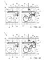
図1A~図1Fは、本発明の第1の例示的な実施形態による、タイヤの製造、すなわちタイヤ成形ドラム(図示せず)に使用されるタイヤ部品9、特にブレーカプライなどのコード補強タイヤ部品を巻き戻すためのアセンブリ1を示す。1A-1F show an
アセンブリ1は、第1の送り込みまたは巻き戻しシステム2と、第2の送り込みまたは巻き戻しシステム3とを備える。第1の巻き戻しシステム2は第1のリールステーション20を備え、第2の巻き戻しシステム3は第2のリールステーション30を備える。各リールステーション20、30は、ストックリール21、31、ライナリール22、23、および巻き戻されているときにタイヤ部品9からライナを剥がすためのピーラ23、33のそれぞれのセットを受け入れるように構成される。ストックリール21、31、ライナリール22、32、およびピーラ23、33は、好ましくは、カートリッジまたはカセットの一部として形成され、単一のユニットとして容易にリールステーション20、30から取り外すか、またはリールステーション20、30に挿入することができる。The
第1の巻き戻しシステム2および第2の巻き戻しシステム3は、各々それぞれのリールステーション20、30の上方に延在する出力コンベヤ24、34をさらに備える。言い換えれば、リールステーション20、30は、それぞれの出力コンベヤ24、34の下に少なくとも部分的に配置される。第1の巻き戻しシステム2および第2の巻き戻しシステム3は、タイヤ成形ドラムに向かって搬送方向Tに出力するために、それぞれのストックリール21、31からそれぞれの出力コンベヤ24、34に連続する長さのタイヤ部品9を交互に供給するように構成される。The
アセンブリ1は、第1の巻き戻しシステム2の出力コンベヤ24からタイヤ部品9をピックアップし、前記ピックアップされたタイヤ部品9を第2の巻き戻しシステム3の出力コンベヤ34上に配置するためのピックアンドプレース部材10と、搬送方向Tの第2の巻き戻しシステム3の下流の、またはタイヤ成形ドラム上に直接配置されたさらなるコンベヤとを備える。この例では、アセンブリ1は、ピックアンドプレース部材10の移動を駆動するためのピックアンドプレース駆動装置11、好ましくはXY駆動装置を備える。アセンブリ1は、第2の巻き戻しシステム3に、またはその下流にカッタ12をさらに備え、カッタ12は、タイヤの製造のためにタイヤ部品9の長さを調整した部品を製造するために、タイヤ部品9を複数のセクションに切断するように構成される。The
タイヤ部品9は、下流のタイヤ製造プロセスへのタイヤ部品9の実質的に連続する供給を維持するために、第1の巻き戻しシステム2または第2の巻き戻しシステム3から交互に巻き戻すことができる。The
出力コンベヤ24、34は、ベルトコンベヤ、ローラコンベヤ、または任意の他の適切なタイプのコンベヤであってもよい。第1の巻き戻しシステム2の出力コンベヤ24は、第2の巻き戻しシステム3の出力コンベヤ34と一直線上に配向され、両方とも移送方向Tと一直線上にある。各出力コンベヤ24、34は、タイヤ部品9を支持するための搬送面25、35を有する。搬送面25、35は、支持平面P内で延在する。The
この例示的な実施形態では、第2の巻き戻しシステム3は、第1の巻き戻しシステム2と同様であるように示されているが、第2の巻き戻しシステム3は、第1の巻き戻しシステム2とは異なる要素を含むことができることを理解されたい。In this exemplary embodiment, the
ここで、本発明は、第1の巻き戻しシステム2のみを参照してさらに詳細に説明される。当業者であれば、以下に記載される特徴および機能は、必要な変更を加えて、第2の巻き戻しシステム3に適用される。The invention will now be described in more detail with reference only to the
図1Aは、リールステーション20内の完全に充填されたストックリール21を有する第1の巻き戻しシステム2を示す。ストックリール21は、ストックリール軸A1の周りを回転可能である。リールステーション20は、ストックリール21の回転を駆動するためのモータ(図示せず)を備えてもよい。ストックリール21からやって来るタイヤ部品9は、タイヤ部品9からライナを分離するためにピーラユニット23を通って渡される。ライナは、ライナリール22に巻き取られる。タイヤ部品9は、出力コンベヤ24に向かって移送するためにピックアップされる準備ができている先端LEを有する。FIG. 1A shows a
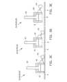
第1の巻き戻しシステム2は、タイヤ部品9の先端LEをリールステーション20から出力コンベヤ24の搬送面25に搬入または移送するように構成された送り込みデバイスまたは移送デバイス4を備える。移送デバイス4は、前述の移送の間にタイヤ部品9の先端LEを保持するための保持部材40を備える。保持部材40およびその動作は、図3A~図3Eにより詳細に示されている。The
図3Aに示されたように、保持部材40は、タイヤ部品9の先端LEを係合および/または保持するための保持面Rを形成または画定する保持体41を備える。この例では、保持体41は、保持要素42を収容するために中空である。保持要素42は、タイヤ部品9を係合し、かつ/または引き付けるように構成され、それによって前記タイヤ部品9が保持体41に保持される。この例における保持部材40は、タイヤ部品9内の金属コードを磁気的に引き付ける磁石の形態の保持要素42を備える。保持要素42は、図3Bに示されたように保持面Rに向かって、かつ/または図3Aおよび図3C~図3Eに示されたように保持面Rから離れて物理的に移動する永久磁石であってもよい。保持要素42は、能動的に、すなわちピストンなどのアクチュエータ43によって移動させられてもよい。あるいは、切り替え可能な電磁石が設けられてもよい。またさらなる代替の実施形態では、タイヤ部品9を真空または針で保持する1つまたは複数の保持要素が設けられてもよい。3A, the holding
保持部材40は、任意選択で、タイヤ部品9が出力コンベヤ24の搬送面25上に移送されたときに、図3Cおよび図3Dに示されたように、タイヤ部品9を押し下げるための押圧要素44、この例では押圧ローラを備えてもよい。The holding
図3A~図3Eは、保持部材40を操作する可能なシーケンスを示す。図3Aは、保持体41が保持平面Rでタイヤ部品9と接触している状況を示し、すなわち、図1Aに示された状況に対応する。ここで、保持要素42は、図3Bに示されたように、すなわち、磁石を保持面Rに向かって移動させることによって作動してもよい。図3Cは、タイヤ部品9が出力コンベヤ24上に移送されたときの図1Bに示された状況に対応する。ここで、保持要素42は、すなわち、磁石を保持面Rから離れるように移動させることによって停止してもよい。押圧部材44は、タイヤ部品が後方にスリップすることを防止するために、タイヤ部品9と依然として押圧接触していてもよい。図3Dは、押圧部材44が依然としてタイヤ部品9を押圧している間に、保持体41がすでにタイヤ部品9から離れて移動している任意選択の状況を示す。図3Eは、保持部材40がタイヤ部品9を完全に解放した状況、すなわち、タイヤ部品9と出力コンベヤ24との間に後方へのスリップを防止するのに十分な摩擦があるときを示す。3A-3E show possible sequences of operation of the holding
図1Aに示されたように、移送デバイス4は、反転軸I1の周りで回転可能なアーム45をさらに備える。反転軸I1は、支持平面Pに平行で搬送方向Tに垂直である。アーム12を反転軸I1の周りで回転させるために、アーム12は、好ましくはモータによって駆動される。アーム45は、図1Aに示された支持平面Pの第2の側におけるピックアップ位置、図1Bに示された解放位置、および図1Cに示された保持位置の間で、誘導経路Sに沿って保持部材40を移動させるように構成される。誘導経路Sは、反転軸I1を中心として少なくとも部分的に半円形である。解放位置および保持位置は、両方とも支持平面Pの第1の側にある。この例では、支持平面Pの第1の側は、支持平面Pの上方の側である。移送デバイス4は、前記誘導経路Sに沿って保持部材40を誘導するための誘導トラック46をさらに備える。保持部材40は、誘導トラック46と係合するためのカム(図示せず)を設けられてもよい。1A, the
図4は、巻き戻しシステム201を有する代替のアセンブリ201を示し、その中で移送デバイス204は、その保持部材240がアーム245に対して反転軸I1に垂直な延在方向Eに移動可能であるという点で、前述された移送デバイス4とは異なる。詳細には、アーム245は、保持部材240の補間的な要素を摺動可能に受け入れるために、延在方向Eに延在する誘導要素、すなわちスロット247を設けられる。結果として、保持部材240は、少なくとも部分的に非円形の誘導経路Sを辿ることができる。保持部材240は、例えば、解放位置を越えてある距離の間搬送方向Tに平行な方向にタイヤ部品9とともに移動することができる。Figure 4 shows an
図1Aおよび図1Bに戻ると、保持部材40は、反転軸I1から離間した旋回軸を中心としてアーム45に対して回転可能であることが示されている。詳細には、旋回軸は誘導経路Sに沿って位置する。したがって、保持部材40は、解放位置および保持位置においてタイヤ部品9を出力コンベヤ24の搬送面25に対して最良に位置決めするように、アーム45に対する向きを適合することができる。そのため、保持面Rの向き、したがって保持面Rに保持されたタイヤ部品9の先端LEの向きは、図1Aに示されたように、タイヤ部品9がピックアップ位置において下向きの第1の側91を有する最初の向きと、タイヤ部品9の前記第1の側91が上向きの最後の向きとの間で反転することができる。詳細には、保持面Rは、支持平面Pに平行で搬送方向Tに垂直な反転軸I1を中心に少なくとも90度にわたって、解放位置とピックアップ位置との間でオフセットまたは回転される。言い換えれば、保持面Rの向き、したがって保持面Rに保持された先端LEの向きは、反転または上下に転倒させることができる。より重要なことに、タイヤ部品9の出力方向は、リールステーション20において搬送方向Tから離れる方向から、搬送方向Tに面する方向または搬送方向Tに平行な方向に、反転または方向転換することができる。1A and 1B, it is shown that the holding
支持平面Pは、前記支持平面Pに垂直または直交する方向に反転軸I1に対して第1の半径で延在する。半円形軌道は、第1の半径よりも大きい第2の半径を有する。したがって、保持部材40は、前記支持平面Pの前記第1の側から前記支持平面Pに向かって移動する前に、半円形軌道に沿って、前記支持平面Pの第1の側の支持平面Pの上方の位置および/または支持平面Pから離間した位置に移動することができる。The support plane P extends at a first radius relative to the inversion axis I1 in a direction perpendicular or orthogonal to said support plane P. The semicircular orbit has a second radius greater than the first radius. Thus, the holding
この例示的な実施形態では、タイヤ部品9がストックリール21の周りに巻き付けられたときに、タイヤ部品9の第1の側91は、ストックリール軸A1に対して半径方向外側に面し、前記第1の側91の反対側の第2の側92は、ストックリール軸A1に対して半径方向内側に面する。ストックリール21は、反時計回りの方向に巻き戻されているように示されているが、ストックリール21からのタイヤ部品9の時計回りの巻き戻しまたは反時計回りの巻き戻しに関して優先順位はないことに留意されたい。保持部材40が、タイヤ部品9の先端LEが保持部材40に保持された状態で解放位置にあるとき、タイヤ部品9の第1の側91は支持平面Pに面している。ストックリール21が代わりに時計回りの方向に巻き戻されるとき、タイヤ部品9の第2の側92は、保持部材40に取り付けられたタイヤ部品9の先端LEが解放位置にあるとき支持平面Pに面している。In this exemplary embodiment, when the
第2の巻き戻しシステム3は、第1の巻き戻しシステム2の保持部材40を有する前述された移送デバイス4と同様または同一の保持部材50を有する移送デバイス5を備える。第2の巻き戻しシステム3の保持部材50は、第1の巻き戻しシステム2の反転軸I1に平行な反転軸I2を中心に回転可能である。The
図1Aに示されたように、ピックアンドプレース部材10は、タイヤ部品9の先端LEを第1の巻き戻しシステム2の出力コンベヤ24から第2の巻き戻しシステム3の出力コンベヤ34に移送するように構成される。ピックアンドプレース部材10は、前述された保持部材40と同様または同一であってもよい(図3A~図3Eを参照)。ピックアンドプレース部材10は、搬送方向Tに平行で支持面Pに垂直な移動平面内で移動可能である。詳細には、アセンブリ1は、上述の移動平面内でピックアンドプレース部材10を移動させるように構成されたピックアンドプレース駆動装置11、好ましくはXY駆動装置を備える。As shown in FIG. 1A, the pick-and-
図5Aおよび図5Bは、前記タイヤ部品9が搬送方向Tとは反対の巻き取り方向Wにストックリール6上に巻き取られているときに、前記タイヤ部品9のしわを低減または解消するためのしわ防止ロール301を有する、本発明の第4の例示的な実施形態による代替の巻き戻しシステム300を示す。代替の巻き戻しシステム300は、しわ防止ロール301をピックアップ位置とストックリール6との間でタイヤ部品9に移動または押圧するためのしわ防止駆動装置302をさらに備える。詳細には、しわ防止駆動装置302は、前記しわ防止ロール301を、リールステーション160の誘導ロール161のうちの1つに対向する作動位置と、前記1つの誘導ロール161からさらに離間した非作動位置との間を移動させる。作動位置において、しわ防止ロール301は、前記1つの誘導ロール161と協働して、タイヤ部品9の任意のしわを押圧し、滑らかにし、かつ/または平らにする。ここで、前述されたアセンブリ1を使用してタイヤ部品9を巻き戻すための方法が、図1A~図1Fを参照して明らかにされる。5A and 5B show an
図1Aは、第1の巻き戻しシステム2の保持部材40が、対応するリールステーション20のピックアップ位置においてタイヤ部品9の先端LEをピックアップした時点を示す。以前に供給されたタイヤ部品9’の後端TEは、第2の巻き戻しシステム3の出力コンベヤ34上に見える。この以前に供給されたタイヤ部品9’は、第1の巻き戻しシステム2におけるタイヤ部品9の巻き戻しとは無関係に、タイヤ成形ドラムに向かってさらに搬送されてもよい。1A shows the moment when the holding
図1Bは、第1の巻き戻しシステム2の移送デバイス4が、タイヤ部品9の先端LEが保持部材40に保持された状態で、第1の巻き戻しシステム2の出力コンベヤ24の搬送面25の真上の支持平面Pの第1の側の解放位置に保持部材40を移動させた状況を示す。解放位置において、タイヤ部品9は、搬送面25に接触して配置または配設される。タイヤ部品の第1の側91は、搬送面25に面し、タイヤ部品9の先端LEは、ここで、搬送方向Tと一致するか、または平行な方向を指している。Figure 1B shows a situation in which the
図1Cは、保持位置にある保持部材40を示し、保持位置では、保持部材40の押圧要素44は、出力コンベヤ24の搬送面25上でタイヤ部品9を押し下げる。これにより、タイヤ部品9の先端が出力コンベヤ24と接触したままであり、出力コンベヤ24がタイヤ部品9を搬送方向Tにさらに搬送することを可能にしながら、重力の影響下で後方にスリップしないことが保証される。Figure 1C shows the holding
さらに、図1Cは、タイヤ部品9の先端LEをそこに保持するために、第1の巻き戻しシステム2の出力コンベヤ24上に位置するタイヤ部品9の先端LEと接触させられたピックアンドプレース部材10を示す。加えて、図1Cは、先端LEの下流のタイヤ部品9の一部分が緩むことが許されることを示す。Furthermore, FIG. 1C shows the pick-and-
図1Dは、ピックアンドプレース部材10が、タイヤ部品9の先端LEを第1の巻き戻しシステム2の出力コンベヤ24から第2の巻き戻しシステム3の出力コンベヤ34に移送したことを示す。ここで、ピックアンドプレース部材10の押圧要素は、任意選択で、第2の巻き戻しシステム3の出力コンベヤ34がタイヤ部品9を搬送方向Tにさらに確実に搬送することができることを保証するために、タイヤ部品9の先端LE上に押し下げられる。このプロセスの間、第2の巻き戻しシステム3の移送デバイス5は、ピックアンドプレース部材10の動作を妨げない位置に移動してもよい。1D shows that the pick-and-
図1Eは、第1の巻き戻しシステム2のリールステーション20内の空のストックリール21と、巻き戻し準備ができている第2の巻き戻しシステム3のリールステーション30内の新しい充填されたストックリール31とを示す。第2の巻き戻しシステム3のリールステーション30内のフルストックリール31は、好都合なことに、第1の巻き戻しシステム2のリールステーション20内のストックリール21が使い果たされる前に置くことができる。未使用のストックリール31からのタイヤ部品9の先端LEは、第2の巻き戻しシステム3の移送デバイス5によって保持される過程にある。この場合、第2の巻き戻しシステム3の移送デバイス5は、タイヤ部品9の先端LEを第2の巻き戻しシステム3の出力コンベヤ34の真上に移送することができるので、アセンブリ1は、出力コンベヤ24と34との間のピックアンドプレースユニット10による移送を除き、ここで、第2の巻き戻しシステム3に対して第1の巻き戻しシステム2について記載されたプロセスを繰り返すことができる。1E shows an
図1Fは、タイヤ部品9の未使用のまたは無駄になった長さが、この例では第2の巻き戻しシステム3のリールステーション30に向かって移送またはフィードバックされている状況を示す。これは、方法の新しいバッチまたは新しいサイクルに切り替える前に出力コンベヤ24をきれいにするために有用であり得る。詳細には、保持部材40は、前記タイヤ部品9の先端LEまたはその近くで、タイヤ部品9の上方の解放位置に配置される。続いて、先端LEが係合される。次いで、アーム45は、解放位置からピックアップ位置に戻されるかまたは後方に回転し、先端LEがストックリール31に戻される。図1A~図1Fは、タイヤ部品9が、移動方向Tから外方に面する出力側Xで第1のリールステーション60および第2のリールステーション160を出る、第1の例示的な実施形態によるアセンブリ1を示している。Figure 1F shows a situation where unused or wasted lengths of
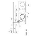
対照的に、図2A、図2B、および図2Cは、タイヤ部品9が、搬送方向Tに面するかまたは向かう代替の出力側X’で巻き戻しシステム102、103を出る、代替のアセンブリ101を示す。言い換えれば、代替のアセンブリ101の巻き戻しシステム102、103は、他方を指しているかまたは向いている。その結果、タイヤ部品9の先端LEは、反転または転倒される必要がない。代わりに、それらは、搬送方向Tに平行で出力コンベヤ124、134によって画定された支持平面Pに垂直な移動平面内で移動するピックアンドプレース部材110によってピックアップおよび解放することができる。代替のアセンブリ101は、上述の移動平面内でピックアンドプレース部材110を移動させるように構成されたピックアンドプレース駆動装置111、好ましくはXY駆動装置を備える。2A, 2B, and 2C, in contrast, show an
出力コンベヤ124、134は、搬送方向Tにおいてそれぞれの巻き戻しシステム102、103の下流に配置されるか、またはそのような位置に移動して、前記ピックアンドプレース部材110の移動を可能にすることができることに留意されたい。詳細には、第1の巻き戻しシステム102の出力コンベヤ124は、第1の巻き戻しシステム102からタイヤ部品9を受け取るために第2の巻き戻しシステム103の少なくとも部分的に上方にある位置と、図2Cに示されたように、第2の巻き戻しシステム103からタイヤ部品9をピックアップするためにピックアンドプレース部材110が出力コンベヤ124と134との間を下方に移動する余地を作る待機位置との間で、搬送方向Tに平行な変位方向Dに移動可能であってもよい。第1の巻き戻しシステム102からタイヤ部品9を巻き戻すときに、タイヤ部品9は、同じ単一のピックアンドプレース部材110により、第1の巻き戻しシステム102の出力コンベヤ124と第2の巻き戻しシステム103の出力コンベヤ134の両方に上に移動する。あるいは、図1A~図1Fのように、出力コンベヤ124と134との間の移送を実行するために、さらなるピックアンドプレース部材が設けられてもよい。It should be noted that the
ピックアンドプレース部材110は、前述された保持部材40と同様または同一の構成を有してもよい(図3A~図3Eを参照)。The pick-and-
上記の説明は、好ましい実施形態の動作を例示するために含まれ、本発明の範囲を限定することを意味しないことを理解されたい。上記の説明から、本発明の範囲によってさらに包含されるはずの多くの変形形態が当業者には明らかになる。It should be understood that the above description is included to illustrate the operation of the preferred embodiment and is not meant to limit the scope of the invention. From the above description, many variations will become apparent to those skilled in the art that are also intended to be encompassed by the scope of the invention.
要約すると、本発明は、ストックリール21からタイヤ部品9を巻き戻し、前記タイヤ部品9を搬送方向Tに出力するための巻き戻しシステム2、アセンブリ1、および方法に関し、巻き戻しシステム2は、リールステーション20と、出力コンベヤ24と、リールステーション20から前記出力コンベヤ24にタイヤ部品9の先端LEを移送するための移送デバイス4とを備え、移送デバイス4は、ピックアップ位置と解放位置との間で誘導経路Sに沿って移動可能な保持部材40を備え、保持部材40は、タイヤ部品9の先端LEを解放可能に保持するための保持面Rを備え、移送デバイス204は、誘導経路Sに沿って保持部材240を移動させるために反転軸I1の周りを回転可能なアーム245をさらに備え、保持部材240は、アーム245に対して反転軸I1に垂直な延在方向Eに移動可能である。In summary, the present invention relates to an
1 アセンブリ
10 ピックアンドプレースユニット
11 駆動装置
12 カッタ
2 第1の巻き戻しシステム
20 リールステーション
21 ストックリール
22 ライナリール
23 ピーラ
24 出力コンベヤ
25 搬送面
3 第2の巻き戻しシステム
30 リールステーション
31 ストックリール
32 ライナリール
33 ピーラ
34 出力コンベヤ
35 搬送面
4 第1の移送デバイス
40 保持部材
41 保持体
42 保持要素
43 アクチュエータ
44 押圧部材
45 アーム
46 誘導トラック
5 第2の移送デバイス
50 保持部材
9 タイヤ部品
91 第1の側
92 第2の側
9’ 以前に供給されたタイヤ部品
101 代替のアセンブリ
110 ピックアンドプレース部材
111 ピックアンドプレース駆動装置
112 カッタ
102 第1の巻き戻しシステム
124 第1の出力コンベヤ
103 第2の巻き戻しシステム
134 第2の出力コンベヤ
201 代替のアセンブリ
202 巻き戻しシステム
204 移送デバイス
240 保持部材
245 アーム
247 スロット
300 代替の巻き戻しシステム
301 しわ防止ロール
302 しわ防止駆動措置
A1 ストックリール軸
A2 ストックリール軸
D 変位方向
E 延在方向
I1 反転軸
I2 反転軸
LE 先端
P 支持平面
R 保持面
S 誘導経路
T 搬送方向
TE 後端
W 巻き取り方向
X 出力側
X’ 代替の出力側1
Claims (8)
Translated fromJapanese前記巻き取りシステムは、前記ストックリールを受け入れるように構成されたリールステーションを備え、前記リールステーションは前記タイヤ部品を誘導するための複数の誘導ロールを備え、
前記巻き取りシステムは、しわ防止ロールと、前記リールステーションの前記複数の誘導ロールのうちの一つと対向する作動位置と前記複数の誘導ロールのうちの一つから離間した非作動位置との間を前記しわ防止ロールを移動させるためのしわ防止駆動装置と、をさらに備える、
巻き取りシステム。 1. A winding system for winding a tire component onto a stock reel in a winding direction, the winding system comprising:
the winding system comprises a reel station configured to receive the stock reel, the reel station comprising a plurality of guide rolls for guiding the tire components;
the winding system further comprising a wrinkle prevention roll and a wrinkle prevention drive for moving the wrinkle prevention roll between an operative position facing one of the plurality of guide rolls of the reel station and a non-operative position spaced from one of the plurality of guide rolls.
Winding system.
前記巻き戻しシステムが、前記タイヤ部品を前記搬送方向に搬送するための出力コンベヤをさらに備え、
前記出力コンベヤは前記搬送方向に平行な支持平面で延在する搬送面を備え、
前記搬送面は、前記ストックリールから前記タイヤ部品を受け取り、前記支持平面の第1の側で前記タイヤ部品を支持するように構成されている、
請求項1に記載の巻き取りシステム。 the winding system is an unwinding system for unwinding the tire component from the stock reel and outputting the tire component in a conveying direction;
the unwinding system further comprising an output conveyor for conveying the tire components in the conveying direction;
the output conveyor having a conveying surface extending in a support plane parallel to the conveying direction;
the transport surface is configured to receive the tire components from the stock reel and support the tire components on a first side of the support plane.
The winding system of claim 1 .
前記搬送面が、前記移送デバイスから前記タイヤ部品を受け取り、前記支持平面の前記第1の側で前記タイヤ部品を支持するように構成され、
前記移送デバイスが、前記リールステーションから前記タイヤ部品の前記先端をピックアップするための前記支持平面の前記第1の側とは反対側の前記支持平面の第2の側におけるピックアップ位置と、前記タイヤ部品の前記先端を前記出力コンベヤの前記搬送面上に配置するための前記支持平面の前記第1の側における解放位置との間で誘導経路に沿って移動可能な保持部材を備える、
請求項2に記載の巻き取りシステム。 the winding system further comprising a transfer device for transferring a leading edge of the tire component from the reel station to the output conveyor;
the conveying surface is configured to receive the tire component from the transport device and support the tire component on the first side of the support plane;
the transfer device comprising a holding member movable along a guide path between a pick-up position on a second side of the support plane opposite the first side of the support plane for picking up the leading edge of the tire component from the reel station and a release position on the first side of the support plane for placing the leading edge of the tire component on the conveying surface of the output conveyor.
The winding system of claim 2.
前記タイヤ部品が前記搬送方向とは反対の巻き上げ方向で前記ストックリールに巻き上げられるときに、前記ピックアップ位置と前記ストックリールとの間で前記しわ防止ロールを前記タイヤ部品に押し付けるステップを含む、方法。 13. A method for winding a tire component onto a stock reel using the winding system of claim 1, comprising the steps of:
pressing the anti-crease roll against the tire component between the pickup location and the stock reel as the tire component is wound onto the stock reel in a winding direction opposite the conveying direction.
前記巻き戻しシステムが、前記ストックリールを受け入れるように構成されたリールステーションと、前記タイヤ部品を前記搬送方向に搬送するための出力コンベヤと、前記タイヤ部品の先端を前記リールステーションから前記出力コンベヤに移送するための移送デバイスとを備え、
前記出力コンベヤは、前記リールステーションの上方に少なくとも部分的に延在し、
前記タイヤ部品の先端を、前記出力コンベヤにおける前記解放位置から前記リールステーションにおける前記ピックアップ位置に戻すステップをさらに含む、
請求項7に記載の方法。
the winding system is an unwinding system;
the unwinding system comprising a reel station configured to receive the stock reel, an output conveyor for conveying the tire components in the conveying direction, and a transfer device for transferring a leading edge of the tire component from the reel station to the output conveyor;
the output conveyor extends at least partially above the reel station;
and returning the leading edge of the tire component from the release position on the output conveyor to the pick-up position on the reel station.
The method of claim 7.
Applications Claiming Priority (6)
| Application Number | Priority Date | Filing Date | Title |
|---|---|---|---|
| NL2028310 | 2021-05-27 | ||
| NL2028312ANL2028312B1 (en) | 2021-05-27 | 2021-05-27 | Unwinding system, assembly and method for unwinding a tire component from a stock reel |
| NL2028312 | 2021-05-27 | ||
| NL2028310ANL2028310B1 (en) | 2021-05-27 | 2021-05-27 | Unwinding system and method for unwinding a tire component from a stock reel and for outputting said tire component in a transport direction |
| JP2022552557AJP7530435B2 (en) | 2021-05-27 | 2022-05-09 | Unwinding system, assembly, and method for unwinding tire components from a stock reel |
| PCT/NL2022/050250WO2022250529A1 (en) | 2021-05-27 | 2022-05-09 | Unwinding system, assembly and method for unwinding a tire component from a stock reel |
Related Parent Applications (1)
| Application Number | Title | Priority Date | Filing Date |
|---|---|---|---|
| JP2022552557ADivisionJP7530435B2 (en) | 2021-05-27 | 2022-05-09 | Unwinding system, assembly, and method for unwinding tire components from a stock reel |
Publications (1)
| Publication Number | Publication Date |
|---|---|
| JP2024153754Atrue JP2024153754A (en) | 2024-10-29 |
Family
ID=81595762
Family Applications (4)
| Application Number | Title | Priority Date | Filing Date |
|---|---|---|---|
| JP2022552556AActiveJP7675734B2 (en) | 2021-05-27 | 2022-05-09 | Unwinding system and method for unwinding a tire component from a stock reel and outputting said tire component in a conveying direction - Patents.com |
| JP2022552557AActiveJP7530435B2 (en) | 2021-05-27 | 2022-05-09 | Unwinding system, assembly, and method for unwinding tire components from a stock reel |
| JP2024120365APendingJP2024153754A (en) | 2021-05-27 | 2024-07-25 | Unwinding system, assembly, and method for unwinding tire components from a stock reel |
| JP2024189264APendingJP2025014007A (en) | 2021-05-27 | 2024-10-28 | Unwinding system and method for unwinding a tire component from a stock reel and outputting said tire component in a conveying direction - Patents.com |
Family Applications Before (2)
| Application Number | Title | Priority Date | Filing Date |
|---|---|---|---|
| JP2022552556AActiveJP7675734B2 (en) | 2021-05-27 | 2022-05-09 | Unwinding system and method for unwinding a tire component from a stock reel and outputting said tire component in a conveying direction - Patents.com |
| JP2022552557AActiveJP7530435B2 (en) | 2021-05-27 | 2022-05-09 | Unwinding system, assembly, and method for unwinding tire components from a stock reel |
Family Applications After (1)
| Application Number | Title | Priority Date | Filing Date |
|---|---|---|---|
| JP2024189264APendingJP2025014007A (en) | 2021-05-27 | 2024-10-28 | Unwinding system and method for unwinding a tire component from a stock reel and outputting said tire component in a conveying direction - Patents.com |
Country Status (10)
| Country | Link |
|---|---|
| US (2) | US20240253928A1 (en) |
| EP (2) | EP4347232A1 (en) |
| JP (4) | JP7675734B2 (en) |
| KR (2) | KR102805180B1 (en) |
| CN (6) | CN115401940A (en) |
| BR (2) | BR112023024565A2 (en) |
| CA (2) | CA3217414A1 (en) |
| MX (2) | MX2023013977A (en) |
| TW (2) | TW202306750A (en) |
| WO (2) | WO2022250529A1 (en) |
Families Citing this family (1)
| Publication number | Priority date | Publication date | Assignee | Title |
|---|---|---|---|---|
| KR102805180B1 (en)* | 2021-05-27 | 2025-05-08 | 브이엠아이 홀랜드 비.브이. | Releasing system, assembly, and method for releasing tire components from storage reels |
Family Cites Families (29)
| Publication number | Priority date | Publication date | Assignee | Title |
|---|---|---|---|---|
| CA965445A (en)* | 1972-08-29 | 1975-04-01 | Uniroyal Ltd. | Mechanized tread booking apparatus and method |
| GB1495803A (en)* | 1974-10-21 | 1977-12-21 | Goodyear Tire & Rubber | Winding and subsequent dispensing of a strip of a tyre building component to a tyre building machine |
| JPS594555A (en) | 1982-06-29 | 1984-01-11 | Yokohama Rubber Co Ltd:The | Feeder for automatic sheet material |
| US4580738A (en)* | 1983-12-05 | 1986-04-08 | The Goodyear Tire & Rubber Company | Controlled tension unwinding system |
| US4951892A (en) | 1988-12-30 | 1990-08-28 | Bridgestone/Firestone, Inc. | Server system for rubberized sheets |
| JPH04371441A (en)* | 1991-06-18 | 1992-12-24 | Bridgestone Corp | Band-like member winder |
| JP2975179B2 (en) | 1991-07-19 | 1999-11-10 | 株式会社ブリヂストン | Sheet-like member gripping mechanism and feeding device |
| DE9213634U1 (en) | 1992-10-09 | 1994-02-10 | Maschinenbau Fecker GmbH, 57439 Attendorn | Device for straightening strip material wound into coils and for introducing it into a feed device of a further processing machine |
| CA2104617A1 (en)* | 1993-04-21 | 1994-10-22 | John Patrick Roman | Method and apparatus for building a tire and storing strip material |
| NL9301717A (en) | 1993-10-06 | 1995-05-01 | Vmi Epe Holland | A method for adapting one side of a strip of flexible material to a reference side and belt strip feeder for feeding a belt strip onto a rotating superstructure drum. |
| JP4053177B2 (en) | 1999-04-09 | 2008-02-27 | 株式会社ブリヂストン | Switching unwinding device for belt-shaped members |
| KR100345414B1 (en)* | 2000-01-05 | 2002-07-26 | 한국타이어 주식회사 | Inner Liner On-Drum Supply System |
| CA2372998A1 (en) | 2002-02-25 | 2003-08-25 | Calstone Inc. | Device for loading rolled material on a work-table |
| JP2004149313A (en) | 2002-11-01 | 2004-05-27 | Fuji Photo Film Co Ltd | Conveying apparatus |
| CN1317120C (en) | 2003-04-30 | 2007-05-23 | 张芝泉 | Automatic producing interlink machine unit of radialply tire inner lining thin film |
| US7661622B2 (en)* | 2005-09-30 | 2010-02-16 | Kimberly-Clark Worldwide, Inc. | Apparatus and method for winding and transporting paper |
| JP2011190061A (en) | 2010-03-15 | 2011-09-29 | Seiko Epson Corp | Sheet member conveying device, and recording device having the same |
| NL2011541C2 (en)* | 2013-10-02 | 2015-04-07 | Vmi Holland Bv | Method for picking up and placing tire components. |
| NL2012253C2 (en)* | 2014-02-12 | 2015-08-17 | Vmi Holland Bv | Tire building machine and method for forming a tire layer, in particular a breaker ply. |
| CN106559349B (en) | 2015-09-24 | 2019-03-19 | 阿里巴巴集团控股有限公司 | Control method and device, the system of service transmission rate |
| JP6838288B2 (en) | 2016-05-30 | 2021-03-03 | 横浜ゴム株式会社 | Band-shaped member joining method and equipment |
| KR101868451B1 (en)* | 2016-09-26 | 2018-06-18 | 금호타이어 주식회사 | Position automatic adjusting device of tire semi-finished products |
| IT201600103467A1 (en) | 2016-10-14 | 2018-04-14 | Ri Flex Abrasives S R L | AUTOMATIC FEEDER |
| NL2018889B1 (en) | 2017-05-10 | 2018-11-15 | Vmi Holland Bv | Wind-up system and method for winding-up a strip |
| CN108582827B (en)* | 2018-04-25 | 2024-07-09 | 天津机电职业技术学院 | Automatic reverse film transferring equipment |
| JP6566084B1 (en)* | 2018-05-17 | 2019-08-28 | 横浜ゴム株式会社 | Apparatus and method for supplying rubber sheet member |
| EP3698959B1 (en)* | 2019-02-19 | 2020-12-16 | Rodolfo Comerio Srl | Unwinding system of reels of a textile substrate particularly for the production of rubber coated cord |
| FR3102088B1 (en)* | 2019-10-21 | 2021-11-05 | Michelin & Cie | Winding and Unwinding of a Strip of Gum and an Interlayer Carrying the Strip of Gum |
| KR102805180B1 (en)* | 2021-05-27 | 2025-05-08 | 브이엠아이 홀랜드 비.브이. | Releasing system, assembly, and method for releasing tire components from storage reels |
- 2022
- 2022-05-09KRKR1020237044836Apatent/KR102805180B1/enactiveActive
- 2022-05-09WOPCT/NL2022/050250patent/WO2022250529A1/ennot_activeCeased
- 2022-05-09BRBR112023024565Apatent/BR112023024565A2/enunknown
- 2022-05-09CACA3217414Apatent/CA3217414A1/enactivePending
- 2022-05-09JPJP2022552556Apatent/JP7675734B2/enactiveActive
- 2022-05-09USUS18/564,557patent/US20240253928A1/enactivePending
- 2022-05-09MXMX2023013977Apatent/MX2023013977A/enunknown
- 2022-05-09EPEP22723207.1Apatent/EP4347232A1/enactivePending
- 2022-05-09CACA3218406Apatent/CA3218406A1/enactivePending
- 2022-05-09KRKR1020237044918Apatent/KR20240013228A/enactivePending
- 2022-05-09MXMX2023013968Apatent/MX2023013968A/enunknown
- 2022-05-09EPEP22722364.1Apatent/EP4347231B1/enactiveActive
- 2022-05-09USUS18/564,573patent/US12286320B2/enactiveActive
- 2022-05-09BRBR112023024560Apatent/BR112023024560A2/enunknown
- 2022-05-09WOPCT/NL2022/050249patent/WO2022250528A1/ennot_activeCeased
- 2022-05-09JPJP2022552557Apatent/JP7530435B2/enactiveActive
- 2022-05-24TWTW111119237Apatent/TW202306750A/enunknown
- 2022-05-24TWTW111119238Apatent/TW202306751A/enunknown
- 2022-05-27CNCN202210593160.6Apatent/CN115401940A/enactivePending
- 2022-05-27CNCN202223252227.4Upatent/CN219095995U/enactiveActive
- 2022-05-27CNCN202221395750.XUpatent/CN218366606U/enactiveActive
- 2022-05-27CNCN202223254074.7Upatent/CN219095996U/enactiveActive
- 2022-05-27CNCN202210593341.9Apatent/CN115401941A/enactivePending
- 2022-05-27CNCN202221395715.8Upatent/CN218140023U/enactiveActive
- 2024
- 2024-07-25JPJP2024120365Apatent/JP2024153754A/enactivePending
- 2024-10-28JPJP2024189264Apatent/JP2025014007A/enactivePending
Also Published As
| Publication number | Publication date |
|---|---|
| CN218366606U (en) | 2023-01-24 |
| KR20240013228A (en) | 2024-01-30 |
| CN218140023U (en) | 2022-12-27 |
| WO2022250528A1 (en) | 2022-12-01 |
| BR112023024565A2 (en) | 2024-02-15 |
| MX2023013968A (en) | 2023-12-11 |
| JP2023531347A (en) | 2023-07-24 |
| KR20240013223A (en) | 2024-01-30 |
| CN115401940A (en) | 2022-11-29 |
| JP2023531348A (en) | 2023-07-24 |
| US20240262065A1 (en) | 2024-08-08 |
| MX2023013977A (en) | 2023-12-12 |
| EP4347231B1 (en) | 2025-10-15 |
| JP7530435B2 (en) | 2024-08-07 |
| EP4347232A1 (en) | 2024-04-10 |
| CA3218406A1 (en) | 2022-12-01 |
| JP7675734B2 (en) | 2025-05-13 |
| WO2022250529A1 (en) | 2022-12-01 |
| KR102805180B1 (en) | 2025-05-08 |
| EP4347231A1 (en) | 2024-04-10 |
| TW202306750A (en) | 2023-02-16 |
| CN115401941A (en) | 2022-11-29 |
| CA3217414A1 (en) | 2022-12-01 |
| BR112023024560A2 (en) | 2024-02-06 |
| US20240253928A1 (en) | 2024-08-01 |
| CN219095996U (en) | 2023-05-30 |
| JP2025014007A (en) | 2025-01-28 |
| TW202306751A (en) | 2023-02-16 |
| US12286320B2 (en) | 2025-04-29 |
| CN219095995U (en) | 2023-05-30 |
Similar Documents
| Publication | Publication Date | Title |
|---|---|---|
| RU2005131611A (en) | AUTOMATIC RELEASE DEVICE FOR CONTINUOUS ACTION FOR SUBMITTING MATERIAL AS A TAPE FROM COILS | |
| US20150360800A1 (en) | System and method for securing free end of wound cable | |
| TWI759473B (en) | Wind-up system and method for winding-up a strip | |
| JP2024153754A (en) | Unwinding system, assembly, and method for unwinding tire components from a stock reel | |
| EP1380526B9 (en) | Web winding method and apparatus therefor | |
| CN115072447A (en) | Material belt processing system | |
| NL2011541C2 (en) | Method for picking up and placing tire components. | |
| EP0943568B1 (en) | Reel feeding method and device | |
| NL2028312B1 (en) | Unwinding system, assembly and method for unwinding a tire component from a stock reel | |
| US20210188584A1 (en) | Method and apparatus for preparing edges of reels of web material | |
| NL2028310B1 (en) | Unwinding system and method for unwinding a tire component from a stock reel and for outputting said tire component in a transport direction | |
| JP2001002322A (en) | Bobbin carrying device | |
| BR112021015807A2 (en) | DEVICE TO REPLACE A COIL IN AN UNCOILER AND RELATED METHOD | |
| JP2004067284A (en) | Film rewinding method and device |
Legal Events
| Date | Code | Title | Description |
|---|---|---|---|
| A621 | Written request for application examination | Free format text:JAPANESE INTERMEDIATE CODE: A621 Effective date:20250428 |