JP2024152271A - Vehicle driving support device - Google Patents
Vehicle driving support deviceDownload PDFInfo
- Publication number
- JP2024152271A JP2024152271AJP2023066359AJP2023066359AJP2024152271AJP 2024152271 AJP2024152271 AJP 2024152271AJP 2023066359 AJP2023066359 AJP 2023066359AJP 2023066359 AJP2023066359 AJP 2023066359AJP 2024152271 AJP2024152271 AJP 2024152271A
- Authority
- JP
- Japan
- Prior art keywords
- steering
- driver
- assist amount
- intervention
- steering assist
- Prior art date
- Legal status (The legal status is an assumption and is not a legal conclusion. Google has not performed a legal analysis and makes no representation as to the accuracy of the status listed.)
- Pending
Links
- 238000001514detection methodMethods0.000claimsabstractdescription24
- 230000008859changeEffects0.000claimsdescription16
- 230000003247decreasing effectEffects0.000claimsdescription5
- 230000007423decreaseEffects0.000claimsdescription3
- 238000010586diagramMethods0.000description12
- 238000000034methodMethods0.000description11
- 230000008569processEffects0.000description8
- 230000009471actionEffects0.000description3
- 230000000694effectsEffects0.000description2
- 238000011156evaluationMethods0.000description2
- 238000012544monitoring processMethods0.000description2
- 230000036651moodEffects0.000description2
- 230000004044responseEffects0.000description2
- 239000000446fuelSubstances0.000description1
- 230000007704transitionEffects0.000description1
Images


Classifications
- B—PERFORMING OPERATIONS; TRANSPORTING
- B62—LAND VEHICLES FOR TRAVELLING OTHERWISE THAN ON RAILS
- B62D—MOTOR VEHICLES; TRAILERS
- B62D5/00—Power-assisted or power-driven steering
- B62D5/04—Power-assisted or power-driven steering electrical, e.g. using an electric servo-motor connected to, or forming part of, the steering gear
- B62D5/0457—Power-assisted or power-driven steering electrical, e.g. using an electric servo-motor connected to, or forming part of, the steering gear characterised by control features of the drive means as such
- B62D5/046—Controlling the motor
- B62D5/0463—Controlling the motor calculating assisting torque from the motor based on driver input
- B—PERFORMING OPERATIONS; TRANSPORTING
- B62—LAND VEHICLES FOR TRAVELLING OTHERWISE THAN ON RAILS
- B62D—MOTOR VEHICLES; TRAILERS
- B62D1/00—Steering controls, i.e. means for initiating a change of direction of the vehicle
- B62D1/24—Steering controls, i.e. means for initiating a change of direction of the vehicle not vehicle-mounted
- B62D1/28—Steering controls, i.e. means for initiating a change of direction of the vehicle not vehicle-mounted non-mechanical, e.g. following a line or other known markers
- B62D1/286—Systems for interrupting non-mechanical steering due to driver intervention
- B—PERFORMING OPERATIONS; TRANSPORTING
- B62—LAND VEHICLES FOR TRAVELLING OTHERWISE THAN ON RAILS
- B62D—MOTOR VEHICLES; TRAILERS
- B62D15/00—Steering not otherwise provided for
- B62D15/02—Steering position indicators ; Steering position determination; Steering aids
- B62D15/025—Active steering aids, e.g. helping the driver by actively influencing the steering system after environment evaluation
Landscapes
- Engineering & Computer Science (AREA)
- Chemical & Material Sciences (AREA)
- Combustion & Propulsion (AREA)
- Transportation (AREA)
- Mechanical Engineering (AREA)
- Steering Control In Accordance With Driving Conditions (AREA)
Abstract
Description
Translated fromJapanese本発明は、車両の運転支援装置に関する。The present invention relates to a vehicle driving assistance device.
目標とする軌道に沿って車両を走行させるための車輪の目標舵角を算出し、実際の舵角をこの目標舵角に制御する技術が存在する。There is technology that calculates a target steering angle for the wheels to drive the vehicle along a target trajectory, and then controls the actual steering angle to this target steering angle.
車両に車線における目標位置、例えば、車線中央から左右へのふらつきが生じた場合に、車両を車線中央へ戻す際の操舵フィーリングには、運転者の好みが存在する。具体的には、運転者によってはふらつきが生じた後、車両をできるだけ早く車線中央へ戻すことを好む場合もあれば、ふらつきの幅(つまり、車線中央からのずれの最大値)を抑えつつも、滑らかな走行性を保つことを好む場合もある。さらに、同じ運転者であっても早く車線中央へ戻したいときもあれば、ある程度のふらつきを許容しながら、滑らかな走行性を保ちたいときもある。When a vehicle begins to stray left or right from a target position in a lane, for example from the center of the lane, drivers have preferences for the steering feeling when returning the vehicle to the center of the lane. Specifically, some drivers prefer to return the vehicle to the center of the lane as quickly as possible after straying, while other drivers prefer to maintain smooth driving characteristics while suppressing the amount of straying (i.e., the maximum deviation from the center of the lane). Furthermore, even the same driver may sometimes want to return the vehicle to the center of the lane quickly, while other times they may want to maintain smooth driving characteristics while tolerating a certain amount of straying.
このような実情に鑑み、本発明は、運転者の好みに応じた操舵フィーリングを実現することのできる車両の運転支援装置を提供することを目的とする。In view of this situation, the present invention aims to provide a vehicle driving assistance device that can realize a steering feeling that meets the driver's preferences.
前記の課題を解決するため、本発明の一形態に係る車両の運転支援装置は、走行車線における車両のふらつきを検知するふらつき検知手段と、ふらつき検知手段により前記車両のふらつきが検知された場合に、前記ふらつきを抑制する操舵トルクのアシスト量である操舵アシスト量を設定する操舵アシスト量設定手段と、運転者による操舵への介入度合いを検出する運転者介入検出手段と、前記運転者介入検出手段により検出された介入度合いに基づき、前記操舵アシスト量を変更する操舵アシスト量変更手段と、運転者が付加する操舵トルクである運転者付加トルクと前記操舵アシスト量変更手段による変更後の前記操舵アシスト量との合計トルクにより、前記車両の操舵を実施する操舵実施手段と、を備える。In order to solve the above problems, a driving assistance device for a vehicle according to one embodiment of the present invention includes a sway detection means for detecting swaying of the vehicle in a driving lane, a steering assist amount setting means for setting a steering assist amount, which is an assist amount of steering torque that suppresses the swaying when swaying of the vehicle is detected by the sway detection means, a driver intervention detection means for detecting the degree of intervention in steering by the driver, a steering assist amount changing means for changing the steering assist amount based on the degree of intervention detected by the driver intervention detection means, and a steering implementation means for steering the vehicle with the total torque of a driver added torque, which is the steering torque added by the driver, and the steering assist amount after change by the steering assist amount changing means.
本発明の一形態によれば、運転者による操舵への介入度合いを検出し、運転者の介入度合いに応じて操舵アシスト量を変更する。これにより、変更後の操舵アシスト量が運転者による操舵への介入度合いに応じたものとなり、運転者の介入度合いを反映させた操舵アシスト量により操舵を実施することが可能となる。よって、運転者の好みに応じた操舵フィーリングを実現することができる。According to one aspect of the present invention, the degree of intervention by the driver in steering is detected, and the steering assist amount is changed according to the degree of intervention by the driver. As a result, the changed steering assist amount corresponds to the degree of intervention by the driver in steering, and steering can be performed with a steering assist amount that reflects the degree of intervention by the driver. Therefore, a steering feeling that matches the driver's preferences can be achieved.
以下に図面を参照して、本発明の実施の形態について説明する。The following describes an embodiment of the present invention with reference to the drawings.
(運転支援装置の構成)
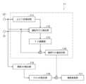
図1は、本発明の一実施形態に係る車両の運転支援装置1の全体的な構成を示す概略図である。(Configuration of driving assistance device)
FIG. 1 is a schematic diagram showing an overall configuration of a vehicle
車両の運転支援装置1は、本実施形態に関わる主な要素として、コントローラ11、外界センサ12、インストルメントパネル13その他、各種センサおよび計器類を備える。運転支援装置1は、他の関連要素として、方向指示器14を備えるとともに、ステアリングアクチュエータ31を備える。ステアリングアクチュエータ31は、電動パワーステアリングシステムの動力源となるものである。ステアリングアクチュエータ31は、例えば、電動モータにより具現され、運転席に備わる走行舵、つまり、ステアリングホイールから操舵軸へ操舵トルクを伝達させる経路上に設けられ、運転者による走行舵の操作を補助するアシストトルクを生成する。The vehicle
コントローラ11は、運転支援装置1の演算部を構成し、演算の結果に応じた指令信号を生成し、出力する。The
外界センサ12は、後に述べる操舵トルクセンサ21とともに運転支援装置1の検出部を構成し、車両の周囲を監視し、周辺の環境または状況に関する情報を取得する。外界センサ12は、前方監視用のセンサとして、車外前方監視カメラ(以下「前方カメラ」という)121および前方ミリ波レーダ122を備える。The
前方カメラ121は、車両の前方に視野が設定され、撮影された画像を解析して、前方に存在する歩行者および障害物を検知するほか、車両が走行している道路および車線(以下「走行車線」という)の状況を検出する。前方カメラ121による検出対象には、路面標示に加え、車道中央線および車道外側線等の区画線が含まれる。車道中央線は、例えば、道路中央部に白色の点線により表示され、車道外側線は、道路と路肩との境界を示すものとして、例えば、道路の外縁に白線により表示される。本実施形態において、前方カメラ121による検出対象である障害物には、路面に設置された固定障害物のほか、自車両に対して同一車線の前方を走行する先行車が含まれる。The
前方カメラ121は、車道中央線および車道外側線の位置をもとに、走行車線の中央位置(以下「車線中央」という)を検出するとともに、車線中央に対する車両の位置の横方向のずれ幅(以下「横方向偏差」という)を検出する。The
図7は、車両Vと走行車線LNdにおける車両Vの目標位置(本実施形態では、車線中央Cl)との関係を示す説明図である。車両Vは、道路Rの左側車線LNdを走行するFigure 7 is an explanatory diagram showing the relationship between the vehicle V and the target position of the vehicle V in the driving lane LNd (in this embodiment, the center of the lane Cl). The vehicle V is traveling in the left lane LNd of the road R.
車両Vの進行方向に対し、道路Rの左側および右側のそれぞれに一車線ずつが設けられ、左側を走行車線LNdとし、右側を対向車線LNoとする。車線中央Clは、車道中央線Lcと車道外側線Leとの中間位置として定められる。図7に示す例では、車線中央Clに対し、車両Vに右側へのふらつきが発生している。横方向偏差Xdは、車両Vの横方向中心(以下「車両中心」という)Cvの車線中央Clに対するずれ幅として、車両中心Cvから右側の区画線(つまり、車道中央線Lc)までの距離Daと、車両中心Cvから左側の区画線(つまり、車道外側線Le)までの距離Dbと、に基づき、計算により検出することが可能である。In the direction of travel of the vehicle V, one lane is provided on each of the left and right sides of the road R, with the left lane being the driving lane LNd and the right lane being the oncoming lane LNo. The lane center Cl is defined as the midpoint between the roadway center line Lc and the roadway outer line Le. In the example shown in FIG. 7, the vehicle V is swaying to the right with respect to the lane center Cl. The lateral deviation Xd can be calculated as the deviation of the lateral center (hereinafter referred to as the "vehicle center") Cv of the vehicle V from the lane center Cl based on the distance Da from the vehicle center Cv to the right lane marking (i.e., the roadway center line Lc) and the distance Db from the vehicle center Cv to the left lane marking (i.e., the roadway outer line Le).
前方ミリ波レーダ122は、車両の前方にミリメートル波長の電波を発射するとともに、障害物等により反射された電波を受信することにより、自車両から障害物等までの距離、障害物等に対する自車両の相対速度等を検出する。The forward
外界センサ12の検出信号は、コントローラ11に出力される。The detection signal of the
インストルメントパネル13は、運転者に状況の認識や注意を促したり、対応を求めたりするためのインジケータを表示する。インストルメントパネル13は、車速等、車両の走行状態を表示する各種メータのほか、表示灯131、警告灯132および警報器133を備える。表示灯131は、トラクションコントロールや車両安定制御等の各種制御およびイモビライザ等の各種装置の作動状態を表示する。警告灯132は、シートベルト非装着や燃料残量不足等、運転者に対する各種の警告を表示する。警告灯132は、メータおよび表示灯131とともに運転席のダッシュボード等、運転者が運転中に視認可能な位置に設置される。警報器133は、警告灯132と連動し、聴覚的な情報の提供により警告に対する運転者の認識を促す。The
以上に加え、運転支援装置1の動作に関わる他のセンサとして、操舵トルクセンサ21および舵角センサ22が設けられる。操舵トルクセンサ21は、運転者により走行舵に付加されるトルク(以下「運転者付加トルク」という)Tstrを検出する。舵角センサ22は、操舵に関わる車輪、一般的には、前輪が向く角度(つまり、車輪方向角であり、以下「舵角」という)θを検出する。舵角θは、前輪の回転軸に垂直な鉛直面と車両Vの前後方向に延びる鉛直面との間に形成される角度である。In addition to the above, a
操舵トルクセンサ21および舵角センサ22の検出信号も、外界センサ12と同様に、コントローラ11に出力される。The detection signals of the
(コントローラの構成)
図2は、運転支援装置1の内部構成を模式的に示す概略図である。(Controller configuration)
FIG. 2 is a schematic diagram showing an internal configuration of the
図2中、コントローラ11のうち、車線維持制御に関わる部分を二点鎖線の枠により示す。In FIG. 2, the part of the
本実施形態において、コントローラ11は、車線中央Clを走行車線LNdにおける車両Vの目標位置とし、車線中央Clを追跡するように車両Vを走行させることにより、走行車線LNdの維持を促す制御(以下「車線維持制御」という)を実施する。車両Vに車線中央Clに対するふらつきが生じた場合に、このふらつきを検知し、ふらつきを抑制する操舵アシスト量ASTを設定する。さらに、運転者による操舵への介入度合いQiを検出し、運転者の介入度合いQiに応じて操舵アシスト量ASTを変更する。In this embodiment, the
ふらつき検知部111は、前方カメラ121の出力情報に基づき、走行車線LNdにおける車両Vのふらつきを検知する。本実施形態において、ふらつきの検知は、前方カメラ121により検出される横方向偏差Xdに基づく。具体的には、横方向偏差Xdが0よりも大きいかまたは0を基準とした所定範囲を逸脱しているか否かを判定することによる。The
運転者介入検出部112は、前方カメラ121および操舵トルクセンサ21の出力情報に基づき、運転者による操舵への介入度合いQiを検出する。具体的には、操舵トルクセンサ21により検出される運転者付加トルクTstrが、運転者による右方向または左方向への実質的なステアリング操作があったことを示す範囲の外側から内側に遷移したか否かを判定し、運転者付加トルクTstrにそのような遷移が生じた場合に、運転者による操舵への介入があったと判定し、その介入の強さ(以下「介入度合い」という)Qiを検出する。The driver
本実施形態において、運転者による操舵への介入があったか否かの判定は、運転者付加トルクTstrの大きさが、上記範囲の境界を定める閾値を増方向へ過ったか否かを判定することによる。In this embodiment, whether or not the driver has intervened in the steering is determined by determining whether or not the magnitude of the driver-added torque Tstr has exceeded the threshold value that defines the boundary of the above range in the increasing direction.
介入度合いQiの検出は、ふらつき量Cdおよびオーバーライド頻度Foの評価による。「ふらつき量」Cdとは、運転者による操舵への介入が生じた際の車両Vのふらつきの傾向を示す指標であり、「オーバーライド頻度」Foとは、運転者による操舵への介入が生じた頻度である。The degree of intervention Qi is detected by evaluating the amount of sway Cd and the override frequency Fo. The "amount of sway" Cd is an index showing the tendency of the vehicle V to sway when the driver intervenes in the steering, and the "override frequency" Fo is the frequency at which the driver intervenes in the steering.
本実施形態では、車両Vに車線中央Clに対して左右の一方へのふらつきが生じ、他方への操舵の切り返しを経て車両Vが車線中央Clに戻るまでの横方向偏差Xdの最大値Xd_maxを所定時間または所定走行距離に亘って検出する。そして、それらの平均値を算出し、この平均値をふらつき量Cdとして検出する。運転者の介入度合いQiは、ふらつき量Cdが大きいほど弱く、小さいほど強いと評価することが可能である。In this embodiment, the maximum value Xd_max of the lateral deviation Xd from the vehicle V when it sways to the left or right of the lane center Cl and the vehicle V returns to the lane center Cl after steering to the other side is detected over a predetermined time or a predetermined travel distance. Then, the average value is calculated and detected as the amount of sway Cd. The degree of driver intervention Qi can be evaluated as weaker the greater the amount of sway Cd, and stronger the smaller the amount of sway Cd.
他方で、単位時間当たりに運転者による操舵への介入があった回数Niを所定時間または所定走行距離に亘って検出し、それらの平均値を算出し、この平均値をオーバーライド頻度Foとして検出する。運転者の介入度合いQiは、オーバーライド頻度Foが低いほど弱く、高いほど強いと評価することが可能である。On the other hand, the number of times Ni that the driver intervenes in steering per unit time is detected over a specified time or a specified distance, and the average value is calculated and detected as the override frequency Fo. The degree of driver intervention Qi can be evaluated as weaker the lower the override frequency Fo, and stronger the higher the frequency Fo.
ゲイン調整部113は、操舵アシスト量ASTの設定に用いられるフィードバックゲインGfを調整する。本実施形態において、操舵アシスト量ASTの設定は、車両Vの横方向偏差Xdに基づき、横方向偏差Xdのふらつきを解消し、車両Vを車線中央Clに戻すのに必要な舵角θの操作量(以下「補正舵角」という)θcを算出する。そして、この補正舵角θcにフィードバックゲインGfを乗算し、トルク相当値に換算することによる。ゲイン調整部113は、運転者介入検出部112により検出された運転者の介入度合いQiに応じてこのフィードバックゲインGfを調整する。フィードバックゲインGfの調整は、次に述べる方法による。The
図6は、ふらつき量Cdおよびオーバーライド頻度Foに対するフィードバックゲインGfの変化の傾向を示すマップである。同図に示すように、フィードバックゲインGfは、運転者による操舵への介入度合いQiが弱いときほど、具体的には、ふらつき量Cdが大きいか、オーバーライド頻度Fоが低いときほど、増大させる。他方で、フィードバックゲインGfは、運転者による操舵への介入度合いQiが強いときほど、具体的には、ふらつき量Cdが小さいか、オーバーライド頻度Fоが高いときほど、減少させる。Figure 6 is a map showing the tendency of change in feedback gain Gf with respect to sway amount Cd and override frequency Fo. As shown in the figure, the feedback gain Gf is increased as the degree of driver intervention in steering Qi becomes weaker, specifically, as the sway amount Cd becomes larger or the override frequency Fo becomes lower. On the other hand, the feedback gain Gf is decreased as the degree of driver intervention in steering Qi becomes stronger, specifically, as the sway amount Cd becomes smaller or the override frequency Fo becomes higher.
操舵アシスト量設定部114は、横方向偏差Xdに相当する状態量である補正舵角θcに調整後のフィードバックゲインGfを乗算し、これにより得られるトルク相当値を、操舵アシスト量ASTに設定する。The steering assist
操舵トルク検出部115は、操舵トルクセンサ21の出力情報をもとに、運転者付加トルクTstrを検出する。The steering
アシストトルク設定部116は、運転者付加トルクTstrに応じたアシストトルクTastを設定する。このアシストトルクTastは、運転者によるステアリング操作を補助する目的で設定され、運転者付加トルクTstrが大きいときほど、増大させる。The assist
操舵実施部117は、操舵アシスト量ASTにアシストトルクTastを加算し、これにより得られる合計トルクTttlを操舵軸に付加することにより、車線中央Clに向けた車両Vの操舵を実施する。具体的には、合計トルクTttlをステアリングアクチュエータ31である電動モータに対する電流指令値(以下「モータ電流指令値」という)Imに換算し、モータ電流指令値Imを電動モータのコントローラに出力する。The
(車線維持制御の内容)
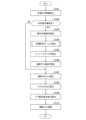
図3は、本実施形態に係る車線維持制御の基本的な流れを示すフローチャートである。コントローラ11は、図3に示すルーチンによる制御を所定の時間ごとに繰り返し実行する。(Lane keeping control details)
3 is a flowchart showing a basic flow of lane keeping control according to this embodiment. The
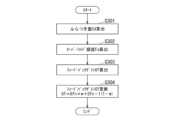
図4は、車線維持制御における目標舵角設定処理の内容を示すフローチャートである。Figure 4 is a flowchart showing the target steering angle setting process for lane keeping control.
図5は、車線維持制御におけるフィードバックゲイン設定処理の内容を示すフローチャートである。Figure 5 is a flowchart showing the feedback gain setting process for lane keeping control.
図3に示すフローチャートにおいて、S101では、外界センサ12等、各種センサの出力情報を読み込む。In the flowchart shown in FIG. 3, in S101, output information from various sensors, such as the
S102では、方向指示器14が停止しているか否かを判定する。方向指示器14が停止している場合は、S103へ進む。他方で、方向指示器14が作動し、点滅している場合は、S107へ進む。方向指示器14が作動している場合は、運転者に車線変更の意思があると判断して、S103~S106に示す処理の実行を一時的に停止する。In S102, it is determined whether the
S103では、車両Vの横方向偏差Xdを検出する。In S103, the lateral deviation Xd of the vehicle V is detected.
S104では、車両Vの目標舵角θt_setを算出する。目標舵角θt_setの算出は、図4のフローチャートに示す手順による。In S104, the target steering angle θt_set of the vehicle V is calculated. The target steering angle θt_set is calculated according to the procedure shown in the flowchart of FIG. 4.
図4に示すフローチャートにおいて、S201では、基本目標舵角θt_bを算出する。基本目標舵角θt_bは、車線中央Clを追跡するように車両Vを走行させるのに必要な舵角であり、基本的には、走行車線LNdの曲率をもとに算出する。例えば、車両Vの前方に目標位置を設定するとともに、車両Vが現在存在する位置の車線中央Clからこの目標位置に至る曲線を仮想的に設定する。そして、この曲線の曲率を算出し、曲率に応じた舵角を基本目標舵角θt-bとする。In the flowchart shown in FIG. 4, in S201, the basic target steering angle θt_b is calculated. The basic target steering angle θt_b is the steering angle required to make the vehicle V travel so as to track the lane center Cl, and is basically calculated based on the curvature of the travel lane LNd. For example, a target position is set in front of the vehicle V, and a curve is virtually set that extends from the lane center Cl where the vehicle V is currently located to this target position. The curvature of this curve is then calculated, and the steering angle according to the curvature is set as the basic target steering angle θt-b.
S202では、横方向偏差Xdに応じた基本目標舵角θt_bの補正量、つまり、補正舵角θcを算出する。In S202, the correction amount of the basic target steering angle θt_b according to the lateral deviation Xd, i.e., the correction steering angle θc, is calculated.
S203では、基本目標舵角θt_bに補正舵角θcを加算することにより、目標舵角θt_setを算出する。In S203, the target steering angle θt_set is calculated by adding the correction steering angle θc to the basic target steering angle θt_b.
図3に示すフローチャートに戻り、S105では、調整後のフィードバックゲインGfを読み込む。フィードバックゲインGfの調整は、図5のフローチャートに示す手順による。Returning to the flowchart shown in FIG. 3, in S105, the adjusted feedback gain Gf is read. The adjustment of the feedback gain Gf follows the procedure shown in the flowchart in FIG. 5.
図5に示すフローチャートにおいて、S301では、車両Vのふらつき量Cdを算出する。In the flowchart shown in FIG. 5, in S301, the amount of sway Cd of the vehicle V is calculated.
S302では、運転者のオーバーライド頻度Foを算出する。In S302, the driver's override frequency Fo is calculated.
S303では、ふらつき量Cdおよびオーバーライド頻度Foをもとに、図6に示すマップを参照して、フィードバックゲインGfを算出する。In S303, the feedback gain Gf is calculated based on the amount of wobble Cd and the override frequency Fo by referring to the map shown in FIG. 6.
S304では、フィードバックゲインGfを更新する。この更新は、例えば、S303の処理により新たに算出されたフィードバックゲインGfnの、現在のフィードバックゲインGfn-1に対する重み付け係数w(0<w<1)を考慮し、次式(1)により行う。
Gf=Gfn×w+Gfn-1×(1-w) …(1) In S304, the feedback gain Gf is updated by, for example, taking into consideration a weighting coefficient w (0<w<1) of the feedback gain Gfn newly calculated in the process of S303 with respect to the current feedback gain Gfn-1, according to the following equation (1).
Gf=Gfn×w+Gfn-1×(1-w)...(1)
図3に示すフローチャートに戻り、S106では、操舵アシスト量ASTを算出する。操舵アシスト量ASTの算出は、目標舵角θt_setと現在舵角との差分Δθを算出し、この差分Δθに更新後のフィードバックゲインGfを乗算することによる。Returning to the flowchart shown in FIG. 3, in S106, the steering assist amount AST is calculated. The steering assist amount AST is calculated by calculating the difference Δθ between the target steering angle θt_set and the current steering angle, and multiplying this difference Δθ by the updated feedback gain Gf.
S107では、運転者付加トルクTstrを検出する。In S107, the driver-added torque Tstr is detected.
S108では、アシストトルクTastを算出する。In S108, the assist torque Tast is calculated.
S109では、モータ電流指令値Imを算出する。モータ電流指令値Imの算出は、操舵アシスト量ASTにアシストトルクTastを加算し、これにより得られる合計トルクTttlを電流指令値に換算することによる。In S109, the motor current command value Im is calculated. The motor current command value Im is calculated by adding the assist torque Tast to the steering assist amount AST and converting the resulting total torque Tttl into a current command value.
S110では、モータ電流指令値Imを電動モータのコントローラに出力し、操舵を実施する。In S110, the motor current command value Im is output to the electric motor controller to perform steering.
(作用および効果の説明)
以下に、本実施形態により得られる作用および効果について説明する。(Explanation of Action and Effects)
The actions and effects obtained by this embodiment will be described below.
本実施形態では、車線LNdを走行中の車両Vにふらつきが生じた場合に、このふらつきを検知し、ふらつきを抑制する操舵アシスト量ASTを設定する。運転者付加トルクTstrに応じたアシストトルクTastとこの操舵アシスト量ASTとの合計トルクTttlにより操舵を実施し、これにより、車両Vのふらつきを抑制し、走行車線LNdの維持を促す。In this embodiment, when the vehicle V traveling in the lane LNd begins to sway, this sway is detected and a steering assist amount AST is set to suppress the sway. Steering is performed with the total torque Tttl of the assist torque Tast corresponding to the driver-added torque Tstr and this steering assist amount AST, thereby suppressing the sway of the vehicle V and encouraging it to maintain the traveling lane LNd.
ここで、運転者による操舵への介入度合いQiを検出し、運転者の介入度合いQiに応じて操舵アシスト量ASTを変更する。操舵アシスト量ASTの変更は、操舵アシスト量ASTの算出に用いられるフィードバックゲインGfを調整することによる。つまり、本実施形態では、フィードバックゲインGfが運転者に応じた操舵フィーリングを実現するための可変因子となる。Here, the degree of intervention Qi by the driver in the steering is detected, and the steering assist amount AST is changed according to the degree of intervention Qi by the driver. The steering assist amount AST is changed by adjusting the feedback gain Gf used to calculate the steering assist amount AST. In other words, in this embodiment, the feedback gain Gf is a variable factor for realizing a steering feeling that suits the driver.
具体的には、操舵への介入度合いQiが強く、自らの操作を優先させて運転することを好む運転者と、操舵への介入度合いQiが弱く、制御システムに頼って運転することを好む運転者とで、フィードバックゲインGfを異ならせる。Specifically, the feedback gain Gf is set differently for a driver who has a strong degree of intervention in steering Qi and prefers to prioritize driving by controlling the vehicle himself, and a driver who has a weak degree of intervention in steering Qi and prefers to rely on the control system to drive.
これにより、本実施形態によれば、操舵アシスト量ASTが運転者による操舵への介入度合いQiに応じたものとなり、運転者の介入度合いQiを反映させた操舵アシスト量ASTにより操舵を実施することで、運転者の好みに応じた操舵フィーリングを実現することが可能となる。As a result, according to this embodiment, the steering assist amount AST corresponds to the degree of intervention Qi by the driver in the steering, and by performing steering with the steering assist amount AST that reflects the degree of intervention Qi by the driver, it is possible to achieve a steering feeling that corresponds to the driver's preferences.
図8は、運転者による操舵への介入度合いQiに応じた車両Vの軌道を模式的に示す説明図である。Figure 8 is an explanatory diagram that shows a schematic diagram of the trajectory of the vehicle V according to the degree of steering intervention Qi by the driver.
図8中、運転者による介入がない場合に車両Vが描く軌道を二点鎖線の曲線TRC1により示し、運転者の介入度合いQiが強い場合に車両Vが描く軌道を細い実線TRC2により示し、運転者の介入度合いQiが弱い場合に車両Vが描く軌道を太い実線TRC3により示す。そして、運転者の介入度合いQiが強い場合と弱い場合との中間の場合に車両Vが描く軌道を破線TRC4により示す。In FIG. 8, the trajectory of the vehicle V when there is no driver intervention is shown by a two-dot chain curve TRC1, the trajectory of the vehicle V when the degree of driver intervention Qi is strong is shown by a thin solid line TRC2, and the trajectory of the vehicle V when the degree of driver intervention Qi is weak is shown by a thick solid line TRC3. And the trajectory of the vehicle V when the degree of driver intervention Qi is intermediate between strong and weak is shown by a dashed line TRC4.
操舵への介入が強い運転者は、車両Vのふらつきが小さいうちに操舵に介入するとともに、ふらつきに対して頻繁に操舵に介入する傾向にある。よって、運転者の介入度合いQiが強い場合の軌道TRC2は、ふらつきの幅(つまり、横方向偏差Xdの最大値Xd_max)が小さくなるとともに、ふらつきの周期が短くなることが想定される。A driver who strongly intervenes in steering tends to intervene in steering while the sway of the vehicle V is still small, and to intervene in steering frequently in response to the sway. Therefore, when the degree of driver intervention Qi is strong, the trajectory TRC2 is expected to have a smaller sway width (i.e., the maximum value Xd_max of the lateral deviation Xd) and a shorter sway period.
これに対し、操舵への介入が強い運転者は、車両Vのふらつきが大きくなってから操舵に介入するとともに、ふらつきに対する操舵への介入も時偶となる傾向にある。よって、運転者の介入度合いQiが弱い場合の軌道TRC3は、ふらつきの幅および周期の双方において、運転者による介入がない場合の軌道TRC1に対して大きな変化がないことが想定される。図8は、運転者の介入度合いQiが弱いことにより、ふらつきの周期には大差がないものの、ふらつきの幅に多少の減少が生じた場合の軌道TRC3を示す。In contrast, a driver who strongly intervenes in steering will only intervene in steering once the vehicle V becomes significantly swayed, and will also tend to intervene in steering in response to the sway only temporarily. Therefore, it is expected that the trajectory TRC3 when the driver's degree of intervention Qi is weak will not change significantly in both the width and period of the sway compared to the trajectory TRC1 when there is no driver intervention. Figure 8 shows the trajectory TRC3 when the driver's degree of intervention Qi is weak, resulting in a slight decrease in the width of the sway, although there is no significant difference in the period of the sway.
本実施形態では、運転者の介入度合いQiとして、運転者が操舵トルクを付加することによる介入が生じた際のふらつきの傾向、つまり、ふらつき量Cdを検出する。これにより、ふらつきが小さいうちに操舵に介入する運転者(介入度合いQiが強く、ふらつき自体を抑制する傾向にある)と、ふらつきが大きくなってから操舵に介入する運転者(介入度合いQiが弱く、ある程度のふらつきを許容する傾向にある)と、のそれぞれに対して適切な操舵アシスト量ASTを設定し、運転者の好みに応じた操舵フィーリングを実現することが可能となる。In this embodiment, the degree of driver intervention Qi is the tendency for swaying when the driver intervenes by applying steering torque, that is, the amount of swaying Cd is detected. This makes it possible to set an appropriate steering assist amount AST for drivers who intervene in steering while the swaying is still small (high degree of intervention Qi, tending to suppress the swaying itself) and drivers who intervene in steering after the swaying becomes large (low degree of intervention Qi, tending to tolerate a certain degree of swaying), and to realize a steering feeling that suits the driver's preferences.
具体的には、ふらつき量Cdが大きいほど、操舵アシスト量ASTを増大させることで、制御システムに頼って運転することを好む運転者に対して適切な操舵アシスト量ASTを設定することが可能となる。反対に、ふらつき量Cdが小さいほど、操舵アシスト量ASTを減少させることで、自らの操作を優先させて運転することを好む運転者に対して適切な操舵アシスト量ASTを設定することが可能となる。Specifically, the larger the amount of sway Cd, the more the steering assist amount AST is increased, making it possible to set an appropriate steering assist amount AST for a driver who prefers to rely on the control system for driving. Conversely, the smaller the amount of sway Cd, the more the steering assist amount AST is decreased, making it possible to set an appropriate steering assist amount AST for a driver who prefers to prioritize their own operation when driving.
ここで、車両Vが車線中央Clから左右の一方へ逸脱し、他方への切り返しを経て車線中央Clに戻るまでの横方向偏差Xdに基づき、ふらつき量Cdを適切かつ容易に検出することが可能となる。横方向偏差Xdの最大値Xd_maxを採用することで、ふらつき量Cdを容易に検出可能とし、さらに、所定時間または所定走行距離当たりの偏差最大値Xd_maxの平均値(例えば、移動平均値)をとることで、運転者の好みを安定的に評価し、一時的な気分のばらつき等が好みの評価に不要な影響を及ぼす事態を回避することができる。Here, it is possible to appropriately and easily detect the amount of sway Cd based on the lateral deviation Xd from the lane center Cl when the vehicle V deviates to the left or right, turns to the other side, and returns to the lane center Cl. By adopting the maximum value Xd_max of the lateral deviation Xd, the amount of sway Cd can be easily detected, and furthermore, by taking the average value (e.g., moving average value) of the maximum deviation Xd_max per a specified time or a specified travel distance, the driver's preferences can be stably evaluated, and a situation in which temporary mood fluctuations, etc., unnecessarily affect the evaluation of preferences can be avoided.
さらに、運転者の介入度合いQiとして、運転者が操舵トルクを付加することによる介入の頻度、つまり、オーバーライド頻度Foを検出する。これにより、操舵トルクを頻繁に付加する運転者(介入度合いQiが強い)と、そうではない運転者(介入度合いQiが弱い)と、のそれぞれに対して適切な操舵アシスト量Qiを設定し、運転者の好みに応じた操舵フィーリングを実現することが可能となる。Furthermore, the frequency of intervention by the driver through the application of steering torque, that is, the override frequency Fo, is detected as the degree of driver intervention Qi. This makes it possible to set an appropriate steering assist amount Qi for drivers who frequently apply steering torque (strong degree of intervention Qi) and drivers who do not (weak degree of intervention Qi), respectively, and to realize a steering feeling that meets the driver's preferences.
具体的には、オーバーライド頻度Foが低いほど、操舵アシスト量ASTを増大させることで、制御システムに頼って運転することを好む運転者に対して適切な操舵アシスト量ASTを設定することが可能となる。反対に、オーバーライド頻度Foが高いほど、操舵アシスト量ASTを減少させることで、自らの操作を優先させて運転することを好む運転者に対して適切な操舵アシスト量ASTを設定することが可能となる。Specifically, the lower the override frequency Fo, the more the steering assist amount AST is increased, making it possible to set an appropriate steering assist amount AST for a driver who prefers to rely on the control system for driving. Conversely, the higher the override frequency Fo, the more the steering assist amount AST is decreased, making it possible to set an appropriate steering assist amount AST for a driver who prefers to prioritize their own operation when driving.
ここで、所定時間または所定走行距離当たりに操舵への介入があった回数Niに基づき、オーバーライド頻度Foを適切かつ容易に検出することが可能となる。さらに、介入があった回数Niの平均値(例えば、移動平均値)をとることで、運転者の好みを安定的に評価し、運転者の一時的な気分のばらつき等が好みの評価に不要な影響を及ぼす事態を回避することができる。Here, it is possible to appropriately and easily detect the override frequency Fo based on the number of times Ni that steering intervention occurred per a specified time or a specified distance. Furthermore, by taking the average value (e.g., moving average value) of the number of times Ni that intervention occurred, it is possible to stably evaluate the driver's preferences and to avoid a situation in which temporary fluctuations in the driver's mood, etc., unnecessarily affect the evaluation of preferences.
以上に加え、本実施形態では、車両の横方向偏差Xdを検出し、横方向偏差Xdまたはこれに相当する状態量にフィードバックゲインGfを乗じて操舵アシスト量ASTを設定するとともに、運転者の介入度合いQiに応じてフィードバックゲインGfを調整する制御構成とした。これにより、操舵アシスト量ASTの設定自体に関わる基本的な制御構成に変更を及ぼすことなく、容易に操舵アシスト量ASTの変更を実現することが可能となる。本実施形態では、補正舵角θcを横方向偏差Xdに相当する状態量として位置付け、補正舵角θcを目標舵角θt_setの設定に反映させることで、横方向偏差Xdに相当する状態量にフィードバックゲインGfが実質的に乗算される構成とする。In addition to the above, in this embodiment, the lateral deviation Xd of the vehicle is detected, and the steering assist amount AST is set by multiplying the lateral deviation Xd or a state quantity equivalent thereto by a feedback gain Gf, and the feedback gain Gf is adjusted according to the degree of driver intervention Qi. This makes it possible to easily change the steering assist amount AST without changing the basic control configuration related to the setting of the steering assist amount AST itself. In this embodiment, the correction steering angle θc is positioned as a state quantity equivalent to the lateral deviation Xd, and the correction steering angle θc is reflected in the setting of the target steering angle θt_set, so that the state quantity equivalent to the lateral deviation Xd is essentially multiplied by the feedback gain Gf.
さらに、図6に示すマップにおいて、フィードバックゲインGfをふらつき量Cdごとに定めた複数の曲線Cd1、Cd2、Cd3を設定し、大きなふらつき量Cdに対する第1曲線Cd1と小さなふらつき量Cdに対する第2曲線Cd2とを比較した場合に、オーバーライド頻度Foが低い領域Aにおいて第1曲線Cd1により定められるフィードバックゲインGf1を、オーバーライド頻度Foが高い領域Bにおいて第2曲線Cd2により定められるフィードバックゲインGf2よりも大きな値に設定した。さらに、オーバーライド頻度Foが低い領域Aにおいて第2曲線Cd2により定められるフィードバックゲインGf3を、オーバーライド頻度Foが高い領域Bにおいて第1曲線Cd1により定められるフィードバックゲインGf4よりも大きな値に設定した。つまり、ふらつき量Cdに応じた複数の曲線Cd1、Cd2、Cd3の間で、フィードバックゲインGfが一部で重複するように設定した。Furthermore, in the map shown in FIG. 6, multiple curves Cd1, Cd2, and Cd3 are set, which determine the feedback gain Gf for each amount of sway Cd. When comparing the first curve Cd1 for a large amount of sway Cd with the second curve Cd2 for a small amount of sway Cd, the feedback gain Gf1 determined by the first curve Cd1 in the region A where the override frequency Fo is low is set to a value larger than the feedback gain Gf2 determined by the second curve Cd2 in the region B where the override frequency Fo is high. Furthermore, the feedback gain Gf3 determined by the second curve Cd2 in the region A where the override frequency Fo is low is set to a value larger than the feedback gain Gf4 determined by the first curve Cd1 in the region B where the override frequency Fo is high. In other words, the feedback gain Gf is set to partially overlap between the multiple curves Cd1, Cd2, and Cd3 according to the amount of sway Cd.
ここで、オーバーライド頻度Foが高い領域Bにおいて第1曲線Cd1によりフィードバックゲインGf4が設定される状況として、運転者による操舵への介入が頻繁であるにも拘らず、ふらつき量Cdが大きく、車両Vのふらつきが抑えられていない状況が想定される。Here, a situation in which the feedback gain Gf4 is set by the first curve Cd1 in region B where the override frequency Fo is high is assumed to be a situation in which the driver frequently intervenes in the steering, but the amount of sway Cd is large and the sway of the vehicle V is not suppressed.
そのような状況では、ふらつきを抑制する方向に補助的な操舵を実施する制御システムの動作に対し、運転者によりふらつきを助長する方向への操舵が実施されていることが考えられる。In such a situation, it is possible that the driver is steering in a direction that increases sway, in contrast to the operation of the control system which performs auxiliary steering in a direction that suppresses sway.
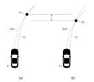
図9は、湾曲路を通過する際に車両Vが描く軌道を示す説明図である。Figure 9 is an explanatory diagram showing the trajectory that vehicle V follows when passing through a curved road.
図9(a)は、車両Vが車線中央Clを追跡するように走行する場合を示し、図9(b)は、車両Vが車線中央Clよりも内側を通過する場合を示す。車線中央Clを追跡する場合は、車両中心Cv1が前方の位置I1で車線中央Clと交わり、その後の車両Vのふらつき量Cdが減少する一方、車線中央Clの内側を通過する場合は、車両中心Cv2が位置I1よりも手前の位置I2で車線中央Clと交わり、その後の車両Vのふらつき量Cdが増大する。Figure 9(a) shows the case where the vehicle V travels so as to track the lane center Cl, and Figure 9(b) shows the case where the vehicle V passes inside the lane center Cl. When tracking the lane center Cl, the vehicle center Cv1 intersects with the lane center Cl at a forward position I1, and the amount of sway Cd of the vehicle V thereafter decreases, whereas when passing inside the lane center Cl, the vehicle center Cv2 intersects with the lane center Cl at a position I2, which is closer than position I1, and the amount of sway Cd of the vehicle V thereafter increases.
本実施形態によれば、図6に示すように、オーバーライド頻度Foが高い領域Bにおいて第1曲線Cd1により定められるフィードバックゲインGf(Gf4)を比較的小さく設定し、具体的には、オーバーライド頻度Foが低い領域Aにおいて第2曲線Cd2により定められるフィードバックゲインGf(Gf3)よりも小さく設定することで、図9(b)に示す場合等、運転者が車線中央Clを追跡するというよりも、自身の好みの走行経路を選択することによりふらつき量Cdがむしろ増大する場合に、運転者が行う操舵を制御システムが過度に邪魔する事態を回避することが可能となる。According to this embodiment, as shown in FIG. 6, the feedback gain Gf (Gf4) determined by the first curve Cd1 is set relatively small in region B where the override frequency Fo is high, specifically, it is set smaller than the feedback gain Gf (Gf3) determined by the second curve Cd2 in region A where the override frequency Fo is low. In this way, it is possible to avoid a situation in which the control system excessively interferes with the steering performed by the driver in cases such as the case shown in FIG. 9(b) where the driver selects his/her preferred driving route rather than tracking the center of the lane Cl, thereby increasing the amount of sway Cd.
以上の説明では、運転者による操舵への介入度合いQiとして、車両Vのふらつき量Cdおよびオーバーライド頻度Foを採用した。運転者の介入度合いQiは、これに限定されるものではなく、他の指標によっても評価することが可能である。介入度合いQiを示す他の指標として、操舵への介入に際して運転者が実際に付加した操舵トルク(実際の運転者付加トルク)を例示することができる。これにより、例えば、ふらつきが生じた際に大きな運転者付加トルクをもって操舵を行う運転者(介入度合いQiが強い)と、そうではない運転者(介入度合いQiが弱い)と、を適切に判定し、それぞれに応じた操舵フィーリングを実現するうえで適切な操舵アシスト量ASTを設定することが可能となる。In the above description, the amount of sway Cd of the vehicle V and the override frequency Fo are used as the degree of intervention Qi by the driver in the steering. The degree of intervention Qi by the driver is not limited to this, and can be evaluated by other indices. Another example of an index showing the degree of intervention Qi is the steering torque actually applied by the driver when intervening in the steering (actual driver-added torque). This makes it possible to appropriately determine, for example, a driver who steers with a large driver-added torque when sway occurs (strong intervention degree Qi) and a driver who does not (weak intervention degree Qi), and to set an appropriate steering assist amount AST to achieve a steering feeling appropriate for each.
具体的には、運転者付加トルクTstrが小さいほど、操舵アシスト量ASTを増大させることで、制御システムに頼って運転することを好む運転者に対し、適切な操舵アシスト量ASTを設定することが可能となる。反対に、運転者付加トルクTstrが大きいほど、操舵アシスト量ASTを減少させることで、自らの操作を優先させて運転することを好む運転者に対して適切な操舵アシスト量ASTを設定することが可能となる。操舵アシスト量ASTの変更は、先の述べた例と同様に、フィードバックゲインGfの調整により行うことが可能である。Specifically, the smaller the driver-added torque Tstr, the greater the steering assist amount AST, making it possible to set an appropriate steering assist amount AST for a driver who prefers to rely on the control system for driving. Conversely, the greater the driver-added torque Tstr, the greater the steering assist amount AST, making it possible to set an appropriate steering assist amount AST for a driver who prefers to prioritize their own operation when driving. The steering assist amount AST can be changed by adjusting the feedback gain Gf, as in the example described above.
さらに、以上の説明では、運転者による操舵への介入度合いQiを継続的に監視し、操舵アシスト量ASTの設定にこれを反映させることとしたが、運転者の介入度合いQiに応じた操舵アシスト量ASTの変更を実施するか否を、運転者の選択により切替可能に構成することもできる。In addition, in the above explanation, the degree of driver's intervention in steering Qi is continuously monitored and reflected in the setting of the steering assist amount AST, but it is also possible to configure the system so that the driver can select whether or not to change the steering assist amount AST according to the driver's intervention degree Qi.
具体的には、運転者による操舵への介入度合いQiを検出し、これに応じてフィードバックゲインGfおよび操舵アシスト量ASTの適合を図る調整動作モードと、予め定められたフィードバックゲインGfを設定することにより、運転者の好みをより直接的に反映可能とする設定動作モードと、を運転者の選択により切替可能とする。Specifically, the system detects the degree of driver intervention in steering Qi and adjusts the feedback gain Gf and steering assist amount AST accordingly, and allows the driver to select between two modes: an adjustment mode, in which a predetermined feedback gain Gf is set, allowing the driver's preferences to be more directly reflected.
そして、設定動作モードでは、例えば、第1モード、第2モードおよび第3モードをさらに選択可能とする。第1モードは、(a1)フィードバックゲインGfとして比較的大きな第1ゲイン(固定値)を設定するか、(a2)フィードバックゲインGfを比較的大きなゲインに切り替えたうえで、これを増大させる際の更新速度を介入度合いQiが小さいときほど増大させるモードとして構成する。第2モードは、(b1)フィードバックゲインGfとして第1モードよりも小さな第2ゲイン(固定値)を設定するか、(b2)フィードバックゲインGfを比較的小さなゲインに切り替えたうえで、これを減少させる際の更新速度を介入度合いQiが大きいときほど増大させるモードとして構成する。第1および第2モードにおいて、フィードバックゲインGfの更新速度は、重み付け係数wを変化させることにより調整可能である。さらに、第3モードは、(c)予め定められたフィードバックゲインGfを設定するモードとして構成する。第3モードにより設定されるフィードバックゲインGfは、デフォルト値であり、その変更を禁止する。Then, in the set operation mode, for example, the first mode, the second mode, and the third mode can be further selected. The first mode is configured as a mode in which (a1) a relatively large first gain (fixed value) is set as the feedback gain Gf, or (a2) the feedback gain Gf is switched to a relatively large gain, and the update speed when increasing the feedback gain Gf is increased as the intervention degree Qi becomes smaller. The second mode is configured as a mode in which (b1) a second gain (fixed value) smaller than the first mode is set as the feedback gain Gf, or (b2) the feedback gain Gf is switched to a relatively small gain, and the update speed when decreasing the feedback gain Gf is increased as the intervention degree Qi becomes larger. In the first and second modes, the update speed of the feedback gain Gf can be adjusted by changing the weighting coefficient w. Furthermore, the third mode is configured as a mode in which (c) a predetermined feedback gain Gf is set. The feedback gain Gf set in the third mode is a default value, and its change is prohibited.
このように、第1モード、第2モードおよび第3モードの間で動作モードを運転者の選択により切替可能としたことで、運転者自身が、フィードバックゲインGfの調整による適合を待たずに、好みの操舵フィーリングが得られるフィードバックゲインGfを直接的に選択することが可能となる。そして、操舵アシスト量ASTの変更自体を好まない運転者は、第3モードの選択により、標準的な操舵フィーリングとして自身の好みを実現することができる。In this way, by allowing the driver to select between the first, second, and third modes, the driver can directly select the feedback gain Gf that provides the steering feeling that he or she prefers, without waiting for the feedback gain Gf to be adjusted to suit the driver. Furthermore, drivers who do not like to change the steering assist amount AST can achieve their preference as a standard steering feeling by selecting the third mode.
さらに、第1モードおよび第2モードに加え、運転者により選択可能な中間モードを設定してもよい。例えば、第1モードの第1ゲイン(固定値)を図6に示すフィードバックゲインGf1程度の大きさに設定するとともに、第2モードの第2ゲイン(固定値)を図6に示すフィードバックゲインGf2程度の大きさに設定する。他方で、中間モードのゲインを第1ゲインGf1と第2ゲインGf2との間の大きさに設定する。中間モードのゲインは、1つのみである必要はなく、ふらつき量Cdが小さく、オーバーライド頻度Foが低い場合のフィードバックゲインGf3に対応するかまたはこれと同程度のゲインと、ふらつき量Cdが大きく、オーバーライド頻度Foが高い場合のフィードバックゲインGf4に対応するかまたはこれと同程度のゲインと、を含む複数のゲインに切替可能であってもよい。In addition to the first and second modes, an intermediate mode selectable by the driver may be set. For example, the first gain (fixed value) in the first mode is set to a magnitude of approximately the feedback gain Gf1 shown in FIG. 6, and the second gain (fixed value) in the second mode is set to a magnitude of approximately the feedback gain Gf2 shown in FIG. 6. On the other hand, the gain in the intermediate mode is set to a magnitude between the first gain Gf1 and the second gain Gf2. The gain in the intermediate mode does not have to be only one, and may be switchable to multiple gains including a gain corresponding to or approximately the same as the feedback gain Gf3 when the sway amount Cd is small and the override frequency Fo is low, and a gain corresponding to or approximately the same as the feedback gain Gf4 when the sway amount Cd is large and the override frequency Fo is high.
1…車両の運転支援装置、11…コントローラ、12…外界センサ、121…前方カメラ、122…前方ミリ波レーダ、13…インストルメントパネル、131…表示灯、132…警告灯、133…警報器、14…方向指示器、14…警告灯、142…警報器、21…操舵トルクセンサ、22…舵角センサ、31…ステアリングアクチュエータ、Cl…車線中央、Cv…車両中心、R…道路、Lc…車道中央線、Le…車道中央線、LNd…走行車線、LNo…対向車線、V…車両。1...vehicle driving assistance device, 11...controller, 12...external sensor, 121...forward camera, 122...forward millimeter wave radar, 13...instrument panel, 131...indicator light, 132...warning light, 133...alarm, 14...direction indicator, 14...warning light, 142...alarm, 21...steering torque sensor, 22...steering angle sensor, 31...steering actuator, Cl...lane center, Cv...vehicle center, R...road, Lc...roadway centerline, Le...roadway centerline, LNd...driving lane, LNo...oncoming lane, V...vehicle.
Claims (12)
Translated fromJapaneseふらつき検知手段により前記車両のふらつきが検知された場合に、前記ふらつきを抑制する操舵トルクのアシスト量である操舵アシスト量を設定する操舵アシスト量設定手段と、
運転者による操舵への介入度合いを検出する運転者介入検出手段と、
前記運転者介入検出手段により検出された介入度合いに基づき、前記操舵アシスト量を変更する操舵アシスト量変更手段と、
運転者が付加する操舵トルクである運転者付加トルクと前記操舵アシスト量変更手段による変更後の前記操舵アシスト量との合計トルクにより、前記車両の操舵を実施する操舵実施手段と、を備える車両の運転支援装置。 A sway detection means for detecting sway of a vehicle in a travel lane;
a steering assist amount setting means for setting a steering assist amount, which is an assist amount of a steering torque for suppressing the sway, when the sway of the vehicle is detected by the sway detection means;
A driver intervention detection means for detecting a degree of intervention in steering by a driver;
a steering assist amount changing means for changing the steering assist amount based on the degree of intervention detected by the driver intervention detection means;
A steering execution means for executing steering of the vehicle using a total torque of a driver applied torque, which is a steering torque applied by a driver, and the steering assist amount after being changed by the steering assist amount change means.
前記操舵アシスト量変更手段は、前記ゲインを前記介入度合いに応じて変更する、請求項1から9のいずれか一項に記載の車両の運転支援装置。 the steering assist amount setting means detects a lateral deviation of a position of the vehicle relative to a target position on a travel lane, and sets the steering assist amount by multiplying the lateral deviation or a state quantity equivalent thereto by a predetermined gain;
The vehicle driving support device according to claim 1 , wherein the steering assist amount change means changes the gain in accordance with the degree of intervention.
前記操舵アシスト量変更手段は、前記ふらつき量が大きい場合の前記ゲインを前記オーバーライド頻度との関係のもとに定める第1曲線と、前記ふらつき量が小さい場合の前記ゲインを前記オーバーライド頻度との関係のもとに定める第2曲線と、が設定され、
前記オーバーライド頻度が高い領域において前記第1曲線により定められる前記ゲインは、前記オーバーライド頻度が低い領域において前記第2曲線により定められる前記ゲインよりも小さい、請求項10に記載の車両の運転支援装置。 The driver intervention detection means detects, as the degree of intervention, a sway amount indicating a tendency of the sway when the driver intervenes in the steering by applying a steering torque, and an override frequency which is a frequency of the intervention;
the steering assist amount change means is set with a first curve that determines the gain when the amount of wobble is large based on a relationship with the override frequency, and a second curve that determines the gain when the amount of wobble is small based on a relationship with the override frequency,
The vehicle driving assistance device according to claim 10 , wherein the gain determined by the first curve in a region where the override frequency is high is smaller than the gain determined by the second curve in a region where the override frequency is low.
前記第3モードが選択された場合に、前記操舵アシスト量変更手段による前記操舵アシスト量の変更を禁止する操舵アシスト量変更禁止手段をさらに備える、請求項10に記載の車両の運転支援装置。
the steering assist amount setting means is configured to be switchable between a first mode in which a relatively large first gain is set as the gain without using the steering assist amount changing means, or an update speed when increasing the gain is increased as the degree of intervention is smaller, a second mode in which a second gain smaller than that in the first mode is set as the gain without using the steering assist amount changing means, or an update speed when decreasing the gain is increased as the degree of intervention is larger, and a third mode in which the gain is preset,
11. The vehicle driving assistance device according to claim 10, further comprising a steering assist amount change prohibiting means for prohibiting the steering assist amount changing means from changing the steering assist amount when the third mode is selected.
Priority Applications (2)
| Application Number | Priority Date | Filing Date | Title |
|---|---|---|---|
| JP2023066359AJP2024152271A (en) | 2023-04-14 | 2023-04-14 | Vehicle driving support device |
| EP24160036.0AEP4464575A1 (en) | 2023-04-14 | 2024-02-27 | Vehicular driving support apparatus |
Applications Claiming Priority (1)
| Application Number | Priority Date | Filing Date | Title |
|---|---|---|---|
| JP2023066359AJP2024152271A (en) | 2023-04-14 | 2023-04-14 | Vehicle driving support device |
Publications (1)
| Publication Number | Publication Date |
|---|---|
| JP2024152271Atrue JP2024152271A (en) | 2024-10-25 |
Family
ID=90097792
Family Applications (1)
| Application Number | Title | Priority Date | Filing Date |
|---|---|---|---|
| JP2023066359APendingJP2024152271A (en) | 2023-04-14 | 2023-04-14 | Vehicle driving support device |
Country Status (2)
| Country | Link |
|---|---|
| EP (1) | EP4464575A1 (en) |
| JP (1) | JP2024152271A (en) |
Family Cites Families (11)
| Publication number | Priority date | Publication date | Assignee | Title |
|---|---|---|---|---|
| JP3982483B2 (en)* | 2003-11-13 | 2007-09-26 | 日産自動車株式会社 | Lane departure prevention device |
| JP4684698B2 (en)* | 2005-03-22 | 2011-05-18 | 本田技研工業株式会社 | Vehicle steering control device |
| JP2006264623A (en)* | 2005-03-25 | 2006-10-05 | Mitsubishi Fuso Truck & Bus Corp | Lane keeping supporting device |
| JP4492471B2 (en)* | 2005-07-25 | 2010-06-30 | トヨタ自動車株式会社 | Power steering device. |
| DE102008057313B4 (en)* | 2008-04-24 | 2018-03-01 | Volkswagen Ag | Method and device for determining a corrective steering torque |
| JP5036780B2 (en)* | 2009-10-06 | 2012-09-26 | トヨタ自動車株式会社 | Vehicle control device |
| US8626392B2 (en)* | 2010-06-23 | 2014-01-07 | Toyota Jidosha Kabushiki Kaisha | Vehicle running control apparatus |
| JP5578331B2 (en) | 2011-12-26 | 2014-08-27 | トヨタ自動車株式会社 | Vehicle trajectory control device |
| DE102014107194A1 (en)* | 2014-05-22 | 2015-11-26 | Robert Bosch Automotive Steering Gmbh | Method for operating a steering system |
| US9592850B1 (en)* | 2016-04-22 | 2017-03-14 | Denso Corporation | Steering control apparatus |
| DE102018126832A1 (en)* | 2018-10-26 | 2020-04-30 | Bayerische Motoren Werke Aktiengesellschaft | Method and control unit for lateral guidance of a vehicle when following a journey |
- 2023
- 2023-04-14JPJP2023066359Apatent/JP2024152271A/enactivePending
- 2024
- 2024-02-27EPEP24160036.0Apatent/EP4464575A1/enactivePending
Also Published As
| Publication number | Publication date |
|---|---|
| EP4464575A1 (en) | 2024-11-20 |
Similar Documents
| Publication | Publication Date | Title |
|---|---|---|
| US20220097696A1 (en) | Vehicular lane centering system | |
| US8838337B2 (en) | Vehicle automatic steering control apparatus | |
| EP2032406B1 (en) | Method and apparatus for using an automated lane keeping system to maintain lateral vehicle spacing | |
| US8521363B2 (en) | Driving assist system | |
| CN107531280B (en) | Steering auxiliary control device for vehicle | |
| US7454291B2 (en) | Driving control apparatus | |
| US8977419B2 (en) | Driving-based lane offset control for lane centering | |
| US20110196576A1 (en) | Method for steering assistance during an emergency maneuver | |
| RU2018109960A (en) | METHOD OF ENSURING RECOMMENDATIONS FOR CHANGE OF TRAFFIC LANE AND THE RELATED SYSTEM | |
| US9227635B1 (en) | Method and system of assisting a driver of a vehicle | |
| JP2018103862A (en) | Driving assistance device | |
| US20160091325A1 (en) | Method and system of assisting a driver of a vehicle | |
| WO2013046293A1 (en) | Vehicle driving assistance system | |
| US10457327B2 (en) | Method and system of assisting a driver of a vehicle | |
| JP5459278B2 (en) | Driving assistance device | |
| US20180201315A1 (en) | Method and system of assisting a driver of a vehicle | |
| JP2014118024A (en) | Lane keeping support device | |
| JP2024152271A (en) | Vehicle driving support device | |
| US20240278831A1 (en) | Travel control device for vehicle | |
| US20170267287A1 (en) | Method and system of assisting a driver of a vehicle | |
| JP2024030217A (en) | Lane departure prevention device | |
| JP7339203B2 (en) | vehicle controller | |
| JP2023065900A (en) | Track deviation prevention device | |
| JP3675155B2 (en) | Light distribution control device for automotive headlights | |
| JP2015150963A (en) | Steering control device for vehicle |