JP2024151845A - Balloon for balloon catheter and balloon catheter - Google Patents
Balloon for balloon catheter and balloon catheterDownload PDFInfo
- Publication number
- JP2024151845A JP2024151845AJP2023065586AJP2023065586AJP2024151845AJP 2024151845 AJP2024151845 AJP 2024151845AJP 2023065586 AJP2023065586 AJP 2023065586AJP 2023065586 AJP2023065586 AJP 2023065586AJP 2024151845 AJP2024151845 AJP 2024151845A
- Authority
- JP
- Japan
- Prior art keywords
- balloon
- section
- distal
- proximal
- ridge
- Prior art date
- Legal status (The legal status is an assumption and is not a legal conclusion. Google has not performed a legal analysis and makes no representation as to the accuracy of the status listed.)
- Pending
Links
- 229920005989resinPolymers0.000claimsdescription21
- 239000011347resinSubstances0.000claimsdescription21
- 239000002184metalSubstances0.000claimsdescription10
- 210000004204blood vesselAnatomy0.000abstractdescription15
- 238000003780insertionMethods0.000abstractdescription5
- 230000037431insertionEffects0.000abstractdescription5
- 239000012530fluidSubstances0.000description14
- 229940079593drugDrugs0.000description11
- 239000003814drugSubstances0.000description11
- 239000011248coating agentSubstances0.000description10
- 229920001971elastomerPolymers0.000description7
- 239000000806elastomerSubstances0.000description7
- 230000002209hydrophobic effectEffects0.000description6
- 239000000463materialSubstances0.000description5
- 239000004952PolyamideSubstances0.000description4
- 238000002347injectionMethods0.000description4
- 239000007924injectionSubstances0.000description4
- 210000003141lower extremityAnatomy0.000description4
- 229920002647polyamidePolymers0.000description4
- -1polytetrafluoroethylenePolymers0.000description4
- 208000031481Pathologic ConstrictionDiseases0.000description3
- 238000002399angioplastyMethods0.000description3
- 238000000576coating methodMethods0.000description3
- 230000007423decreaseEffects0.000description3
- 210000003090iliac arteryAnatomy0.000description3
- 238000004519manufacturing processMethods0.000description3
- 239000003550markerSubstances0.000description3
- 229920006122polyamide resinPolymers0.000description3
- 230000036262stenosisEffects0.000description3
- 208000037804stenosisDiseases0.000description3
- OKTJSMMVPCPJKN-UHFFFAOYSA-NCarbonChemical compound[C]OKTJSMMVPCPJKN-UHFFFAOYSA-N0.000description2
- RTZKZFJDLAIYFH-UHFFFAOYSA-NDiethyl etherChemical compoundCCOCCRTZKZFJDLAIYFH-UHFFFAOYSA-N0.000description2
- 239000004812Fluorinated ethylene propyleneSubstances0.000description2
- JHWNWJKBPDFINM-UHFFFAOYSA-NLaurolactamChemical compoundO=C1CCCCCCCCCCCN1JHWNWJKBPDFINM-UHFFFAOYSA-N0.000description2
- 229920000299Nylon 12Polymers0.000description2
- 239000004813Perfluoroalkoxy alkaneSubstances0.000description2
- 210000003363arteriovenous anastomosisAnatomy0.000description2
- 239000008280bloodSubstances0.000description2
- 210000004369bloodAnatomy0.000description2
- 229910052799carbonInorganic materials0.000description2
- 229920001577copolymerPolymers0.000description2
- 201000010099diseaseDiseases0.000description2
- 208000037265diseases, disorders, signs and symptomsDiseases0.000description2
- 238000001415gene therapyMethods0.000description2
- 238000000465mouldingMethods0.000description2
- 229920009441perflouroethylene propylenePolymers0.000description2
- 229920011301perfluoro alkoxyl alkanePolymers0.000description2
- 229920001225polyester resinPolymers0.000description2
- 239000004645polyester resinSubstances0.000description2
- 229920006146polyetheresteramide block copolymerPolymers0.000description2
- 229920001343polytetrafluoroethylenePolymers0.000description2
- 239000004810polytetrafluoroethyleneSubstances0.000description2
- 229920005749polyurethane resinPolymers0.000description2
- ZAHRKKWIAAJSAO-UHFFFAOYSA-NrapamycinNatural productsCOCC(O)C(=C/C(C)C(=O)CC(OC(=O)C1CCCCN1C(=O)C(=O)C2(O)OC(CC(OC)C(=CC=CC=CC(C)CC(C)C(=O)C)C)CCC2C)C(C)CC3CCC(O)C(C3)OC)CZAHRKKWIAAJSAO-UHFFFAOYSA-N0.000description2
- 208000037803restenosisDiseases0.000description2
- 229960002930sirolimusDrugs0.000description2
- QFJCIRLUMZQUOT-HPLJOQBZSA-NsirolimusChemical compoundC1C[C@@H](O)[C@H](OC)C[C@@H]1C[C@@H](C)[C@H]1OC(=O)[C@@H]2CCCCN2C(=O)C(=O)[C@](O)(O2)[C@H](C)CC[C@H]2C[C@H](OC)/C(C)=C/C=C/C=C/[C@@H](C)C[C@@H](C)C(=O)[C@H](OC)[C@H](O)/C(C)=C/[C@@H](C)C(=O)C1QFJCIRLUMZQUOT-HPLJOQBZSA-N0.000description2
- KKJUPNGICOCCDW-UHFFFAOYSA-N7-N,N-Dimethylamino-1,2,3,4,5-pentathiocyclooctaneChemical compoundCN(C)C1CSSSSSC1KKJUPNGICOCCDW-UHFFFAOYSA-N0.000description1
- 206010002383Angina PectorisDiseases0.000description1
- HKVAMNSJSFKALM-GKUWKFKPSA-NEverolimusChemical compoundC1C[C@@H](OCCO)[C@H](OC)C[C@@H]1C[C@@H](C)[C@H]1OC(=O)[C@@H]2CCCCN2C(=O)C(=O)[C@](O)(O2)[C@H](C)CC[C@H]2C[C@H](OC)/C(C)=C/C=C/C=C/[C@@H](C)C[C@@H](C)C(=O)[C@H](OC)[C@H](O)/C(C)=C/[C@@H](C)C(=O)C1HKVAMNSJSFKALM-GKUWKFKPSA-N0.000description1
- YCKRFDGAMUMZLT-UHFFFAOYSA-NFluorine atomChemical compound[F]YCKRFDGAMUMZLT-UHFFFAOYSA-N0.000description1
- 244000043261Hevea brasiliensisSpecies0.000description1
- 229920000571Nylon 11Polymers0.000description1
- 229930012538PaclitaxelNatural products0.000description1
- 239000004698PolyethyleneSubstances0.000description1
- 239000002202Polyethylene glycolSubstances0.000description1
- 239000004734Polyphenylene sulfideSubstances0.000description1
- 239000004743PolypropyleneSubstances0.000description1
- 239000004372Polyvinyl alcoholSubstances0.000description1
- 206010057469Vascular stenosisDiseases0.000description1
- 239000013543active substanceSubstances0.000description1
- 239000000654additiveSubstances0.000description1
- 230000000996additive effectEffects0.000description1
- 239000000853adhesiveSubstances0.000description1
- 230000001070adhesive effectEffects0.000description1
- 125000000217alkyl groupChemical group0.000description1
- 230000001028anti-proliverative effectEffects0.000description1
- 210000000702aorta abdominalAnatomy0.000description1
- 238000005452bendingMethods0.000description1
- 230000015572biosynthetic processEffects0.000description1
- 230000017531blood circulationEffects0.000description1
- 238000000071blow mouldingMethods0.000description1
- 239000000919ceramicSubstances0.000description1
- 239000003795chemical substances by applicationSubstances0.000description1
- 230000008602contractionEffects0.000description1
- 210000004351coronary vesselAnatomy0.000description1
- 229910003460diamondInorganic materials0.000description1
- 239000010432diamondSubstances0.000description1
- 238000002224dissectionMethods0.000description1
- 230000000694effectsEffects0.000description1
- HQQADJVZYDDRJT-UHFFFAOYSA-Nethene;prop-1-eneChemical groupC=C.CC=CHQQADJVZYDDRJT-UHFFFAOYSA-N0.000description1
- 229960005167everolimusDrugs0.000description1
- 229910052731fluorineInorganic materials0.000description1
- 239000011737fluorineSubstances0.000description1
- 238000002594fluoroscopyMethods0.000description1
- 238000001631haemodialysisMethods0.000description1
- 230000012447hatchingEffects0.000description1
- 230000000322hemodialysisEffects0.000description1
- 229920001477hydrophilic polymerPolymers0.000description1
- 229960003444immunosuppressant agentDrugs0.000description1
- 239000003018immunosuppressive agentSubstances0.000description1
- 238000005304joiningMethods0.000description1
- 229920000126latexPolymers0.000description1
- 230000003902lesionEffects0.000description1
- 238000000034methodMethods0.000description1
- 208000010125myocardial infarctionDiseases0.000description1
- 229920003052natural elastomerPolymers0.000description1
- 229920001194natural rubberPolymers0.000description1
- 229960001592paclitaxelDrugs0.000description1
- 125000005010perfluoroalkyl groupChemical group0.000description1
- 229920002401polyacrylamidePolymers0.000description1
- 229920000728polyesterPolymers0.000description1
- 229920000573polyethylenePolymers0.000description1
- 229920001223polyethylene glycolPolymers0.000description1
- 229920000139polyethylene terephthalatePolymers0.000description1
- 239000005020polyethylene terephthalateSubstances0.000description1
- 229920005672polyolefin resinPolymers0.000description1
- 229920000069polyphenylene sulfidePolymers0.000description1
- 229920001155polypropylenePolymers0.000description1
- 229920002635polyurethanePolymers0.000description1
- 239000004814polyurethaneSubstances0.000description1
- 229920003225polyurethane elastomerPolymers0.000description1
- 229920002451polyvinyl alcoholPolymers0.000description1
- 229920000036polyvinylpyrrolidonePolymers0.000description1
- 239000001267polyvinylpyrrolidoneSubstances0.000description1
- 235000013855polyvinylpyrrolidoneNutrition0.000description1
- 230000000717retained effectEffects0.000description1
- 229920002545silicone oilPolymers0.000description1
- 229920002050silicone resinPolymers0.000description1
- 150000003384small moleculesChemical class0.000description1
- 239000000126substanceSubstances0.000description1
- 230000003746surface roughnessEffects0.000description1
- RCINICONZNJXQF-MZXODVADSA-NtaxolChemical compoundO([C@@H]1[C@@]2(C[C@@H](C(C)=C(C2(C)C)[C@H](C([C@]2(C)[C@@H](O)C[C@H]3OC[C@]3([C@H]21)OC(C)=O)=O)OC(=O)C)OC(=O)[C@H](O)[C@@H](NC(=O)C=1C=CC=CC=1)C=1C=CC=CC=1)O)C(=O)C1=CC=CC=C1RCINICONZNJXQF-MZXODVADSA-N0.000description1
- 229920002803thermoplastic polyurethanePolymers0.000description1
- 229920005992thermoplastic resinPolymers0.000description1
- 210000004026tunica intimaAnatomy0.000description1
- 230000002792vascularEffects0.000description1
- 238000003466weldingMethods0.000description1
- CGTADGCBEXYWNE-JUKNQOCSSA-NzotarolimusChemical compoundN1([C@H]2CC[C@@H](C[C@@H](C)[C@H]3OC(=O)[C@@H]4CCCCN4C(=O)C(=O)[C@@]4(O)[C@H](C)CC[C@H](O4)C[C@@H](/C(C)=C/C=C/C=C/[C@@H](C)C[C@@H](C)C(=O)[C@H](OC)[C@H](O)/C(C)=C/[C@@H](C)C(=O)C3)OC)C[C@H]2OC)C=NN=N1CGTADGCBEXYWNE-JUKNQOCSSA-N0.000description1
- 229950009819zotarolimusDrugs0.000description1
Images


Classifications
- A—HUMAN NECESSITIES
- A61—MEDICAL OR VETERINARY SCIENCE; HYGIENE
- A61M—DEVICES FOR INTRODUCING MEDIA INTO, OR ONTO, THE BODY; DEVICES FOR TRANSDUCING BODY MEDIA OR FOR TAKING MEDIA FROM THE BODY; DEVICES FOR PRODUCING OR ENDING SLEEP OR STUPOR
- A61M25/00—Catheters; Hollow probes
- A61M25/10—Balloon catheters
- A61M25/104—Balloon catheters used for angioplasty
- A—HUMAN NECESSITIES
- A61—MEDICAL OR VETERINARY SCIENCE; HYGIENE
- A61M—DEVICES FOR INTRODUCING MEDIA INTO, OR ONTO, THE BODY; DEVICES FOR TRANSDUCING BODY MEDIA OR FOR TAKING MEDIA FROM THE BODY; DEVICES FOR PRODUCING OR ENDING SLEEP OR STUPOR
- A61M25/00—Catheters; Hollow probes
- A61M25/10—Balloon catheters
- A61M25/1002—Balloon catheters characterised by balloon shape
- A—HUMAN NECESSITIES
- A61—MEDICAL OR VETERINARY SCIENCE; HYGIENE
- A61M—DEVICES FOR INTRODUCING MEDIA INTO, OR ONTO, THE BODY; DEVICES FOR TRANSDUCING BODY MEDIA OR FOR TAKING MEDIA FROM THE BODY; DEVICES FOR PRODUCING OR ENDING SLEEP OR STUPOR
- A61M25/00—Catheters; Hollow probes
- A61M25/10—Balloon catheters
- A61M2025/1043—Balloon catheters with special features or adapted for special applications
- A61M2025/1086—Balloon catheters with special features or adapted for special applications having a special balloon surface topography, e.g. pores, protuberances, spikes or grooves
- A—HUMAN NECESSITIES
- A61—MEDICAL OR VETERINARY SCIENCE; HYGIENE
- A61M—DEVICES FOR INTRODUCING MEDIA INTO, OR ONTO, THE BODY; DEVICES FOR TRANSDUCING BODY MEDIA OR FOR TAKING MEDIA FROM THE BODY; DEVICES FOR PRODUCING OR ENDING SLEEP OR STUPOR
- A61M2210/00—Anatomical parts of the body
- A61M2210/12—Blood circulatory system
Landscapes
- Health & Medical Sciences (AREA)
- Life Sciences & Earth Sciences (AREA)
- Heart & Thoracic Surgery (AREA)
- Biomedical Technology (AREA)
- Biophysics (AREA)
- Pulmonology (AREA)
- Engineering & Computer Science (AREA)
- Anesthesiology (AREA)
- Child & Adolescent Psychology (AREA)
- Hematology (AREA)
- Animal Behavior & Ethology (AREA)
- General Health & Medical Sciences (AREA)
- Public Health (AREA)
- Veterinary Medicine (AREA)
- Vascular Medicine (AREA)
- Media Introduction/Drainage Providing Device (AREA)
Abstract
Description
Translated fromJapanese本発明は、バルーンカテーテル用バルーンと当該バルーンを備えたバルーンカテーテルに関するものである。The present invention relates to a balloon for a balloon catheter and a balloon catheter equipped with the balloon.
体内で血液が循環するための流路である血管に狭窄が生じ、血液の循環が滞ることにより、様々な疾患が発生することが知られている。特に心臓に血液を供給する冠状動脈に狭窄が生じると、狭心症、心筋梗塞等の重篤な疾病をもたらすおそれがある。このような血管の狭窄部を治療する方法の一つとして、バルーンカテーテルを用いて狭窄部を拡張させる血管形成術(PTA、PTCA等)がある。It is known that stenosis in blood vessels, which are the channels through which blood circulates in the body, can lead to various diseases due to stagnation of blood circulation. In particular, stenosis in the coronary arteries that supply blood to the heart can lead to serious diseases such as angina pectoris and myocardial infarction. One method of treating such vascular stenosis is angioplasty (PTA, PTCA, etc.), which uses a balloon catheter to expand the stenosis.
バルーンカテーテルには、バルーンの表面に凸条が設けられたものが知られている(例えば、特許文献1~3)。このようなバルーンカテーテルを用いれば、バルーンを拡張させた際に、バルーンの凸条を狭窄部に食い込ませて、狭窄部を効果的に拡張させることができる。一方、凸条が設けられたバルーンは、凸条が設けられた部分で剛性が高くなる傾向を示し、長手軸方向の屈曲性が低下しやすくなる。これに対して、バルーン表面の凸条に切欠きが形成されたバルーンカテーテルが知られている(例えば、特許文献4、5)。このようなバルーンカテーテルを用いれば、凸条が設けられたバルーンであっても長手軸方向の屈曲性を確保することができる。There are known balloon catheters with ridges on the surface of the balloon (e.g.,
バルーン表面に凸条が設けられ、当該凸条に切欠きが形成されたバルーンは、凸条によってスコアリング機能を発揮することができるとともに、凸条に形成された切欠きによってバルーンの長手軸方向の屈曲性を確保することができる。一方、血管には大きく屈曲した屈曲部が存在することから、そのような屈曲部であっても、凸条が設けられたバルーンをスムーズに挿通できることが望まれる。A balloon with ridges on its surface and notches formed in the ridges can provide a scoring function through the ridges, and the notches formed in the ridges ensure flexibility in the longitudinal direction of the balloon. However, blood vessels have bent parts that are greatly bent, so it is desirable to be able to smoothly insert a balloon with ridges even in such bent parts.
本発明は前記事情に鑑みてなされたものであり、その目的は、表面に凸条が設けられたバルーンであって、血管等の屈曲部への挿通性を高めることができ、凸条によるスコアリング機能が確保することができるバルーンカテーテル用バルーンと当該バルーンを備えたバルーンカテーテルを提供することにある。The present invention was made in consideration of the above circumstances, and its purpose is to provide a balloon for a balloon catheter, which has a ridge on its surface, and which can improve insertion into curved parts of blood vessels and the like, and which can ensure a scoring function due to the ridge, and a balloon catheter equipped with the balloon.
前記課題を解決することができた本発明のバルーンカテーテル用バルーンおよび当該バルーンを備えたバルーンカテーテルは、下記の通りである。
[1] 近位側から遠位側に延びる長手軸方向と、前記長手軸方向に垂直な径方向と周方向とを有するバルーンカテーテル用バルーンであって、
前記バルーンは、直管部と、前記直管部よりも近位側に位置する近位側テーパー部と、前記直管部よりも遠位側に位置する遠位側テーパー部とを有し、
前記直管部は、筒形状のバルーン本体部と、前記バルーン本体部の外面に、径方向の外方に突出し長手軸方向に延びる凸条とを有し、前記凸条は前記直管部の周方向に複数設けられ、
前記各凸条には切欠きが形成されており、
前記各凸条において、前記凸条を長手軸方向に3等分し近位区間、中間区間、遠位区間に区分したとき、前記近位区間に設けられた前記切欠きの数と前記遠位区間に設けられた前記切欠きの数はそれぞれ、前記中間区間に設けられた前記切欠きの数よりも多いバルーンカテーテル用バルーン。
[2] 前記近位区間を長手軸方向に2等分し近位側から第1近位区間と第2近位区間としたとき、少なくとも前記第1近位区間に前記切欠きが設けられている、および/または、前記遠位区間を長手軸方向に2等分し遠位側から第1遠位区間と第2遠位区間としたとき、少なくとも前記第1遠位区間に前記切欠きが設けられている[1]に記載のバルーン。
[3] 少なくとも前記第1近位区間と前記第1遠位区間に前記切欠きが設けられている[2]に記載のバルーン。
[4] 前記各凸条は、前記切欠きによって区分された複数の凸条セグメントを有し、前記各凸条において、長手軸方向に隣接する前記凸条セグメントの長手軸方向の長さは、互いに同じか、長手軸方向の中央側に位置する前記凸条セグメントの方が長い[1]~[3]のいずれかに記載のバルーン。
[5] 前記各凸条の前記中間区間には前記切欠きが設けられない[1]~[4]のいずれかに記載のバルーン。
[6] 前記凸条は、樹脂製、金属製、またはその組み合わせである[1]~[5]のいずれかに記載のバルーン。
[7] 前記直管部の長手軸方向の長さは50mm以上である[1]~[6]のいずれかに記載のバルーン。
[8] [1]~[7]のいずれかに記載のバルーンを備えるバルーンカテーテル。 The balloon for a balloon catheter and the balloon catheter including the balloon of the present invention, which are able to solve the above-mentioned problems, are as follows.
[1] A balloon for a balloon catheter having a longitudinal axis direction extending from a proximal side to a distal side, and a radial direction and a circumferential direction perpendicular to the longitudinal axis direction,
The balloon has a straight tube portion, a proximal tapered portion located proximally of the straight tube portion, and a distal tapered portion located distally of the straight tube portion,
The straight pipe portion has a cylindrical balloon main body and a protrusion on an outer surface of the balloon main body that protrudes radially outward and extends in a longitudinal axis direction, and the protrusion is provided in a plurality of circumferential directions of the straight pipe portion.
Each of the protrusions has a notch formed therein,
When each of the ridges is divided into thirds in the longitudinal direction into a proximal section, an intermediate section, and a distal section, the number of the notches provided in the proximal section and the number of the notches provided in the distal section are each greater than the number of the notches provided in the intermediate section.
[2] The balloon described in [1], wherein when the proximal section is divided in two in the longitudinal direction into a first proximal section and a second proximal section from the proximal side, the notch is provided in at least the first proximal section, and/or, when the distal section is divided in two in the longitudinal direction into a first distal section and a second distal section from the distal side, the notch is provided in at least the first distal section.
[3] The balloon according to [2], wherein the notch is provided in at least the first proximal section and the first distal section.
[4] The balloon described in any one of [1] to [3], wherein each of the ridges has a plurality of ridge segments divided by the notches, and in each of the ridges, the lengths of the ridge segments adjacent to each other in the longitudinal direction are equal to each other or the ridge segment located toward the center in the longitudinal direction is longer.
[5] The balloon according to any one of [1] to [4], wherein the notch is not provided in the intermediate section of each of the ridges.
[6] The balloon according to any one of [1] to [5], wherein the ridges are made of resin, metal, or a combination thereof.
[7] The balloon according to any one of [1] to [6], wherein the straight tube portion has a length in the longitudinal direction of 50 mm or more.
[8] A balloon catheter comprising the balloon according to any one of [1] to [7].
本発明のバルーンカテーテル用バルーンは、バルーンの直管部の外面に凸条が設けられているため、当該バルーンを備えたバルーンカテーテルを用いて血管の狭窄部等においてバルーンを拡張させると、凸条が狭窄部等に食い込んで効果的に拡張させることができる。また、バルーンの各凸条に切欠きが形成され、切欠きが各凸条の近位区間と遠位区間により多く設けられているため、バルーンを屈曲部に挿通させることが容易になる。一方、各凸条の中間区間には切欠きが設けられないかより少ない数の切欠きが設けられるため、凸条によるスコアリング機能を確保することができる。The balloon for balloon catheter of the present invention has a convex rib on the outer surface of the straight tube part of the balloon, so that when a balloon catheter equipped with the balloon is used to expand the balloon at a narrowed part of a blood vessel, the convex rib can bite into the narrowed part and effectively expand it. In addition, notches are formed on each convex rib of the balloon, and more notches are provided in the proximal and distal sections of each convex rib, making it easier to insert the balloon through a bent part. On the other hand, no notches or a smaller number of notches are provided in the intermediate section of each convex rib, so the scoring function of the convex rib can be ensured.
以下、下記実施の形態に基づき本発明を具体的に説明するが、本発明はもとより下記実施の形態によって制限を受けるものではなく、前・後記の趣旨に適合し得る範囲で適当に変更を加えて実施することも勿論可能であり、それらはいずれも本発明の技術的範囲に包含される。なお、各図面において、便宜上、ハッチングや部材符号等を省略する場合もあるが、かかる場合、明細書や他の図面を参照するものとする。また、図面における種々部材の寸法は、本発明の特徴の理解に資することを優先しているため、実際の寸法とは異なる場合がある。The present invention will be described in detail below based on the following embodiment, but the present invention is not limited to the following embodiment, and can of course be modified appropriately within the scope of the above and below, all of which are included in the technical scope of the present invention. In addition, hatching and component symbols may be omitted in each drawing for convenience, but in such cases, reference should be made to the specification or other drawings. Furthermore, the dimensions of various components in the drawings may differ from the actual dimensions, as priority is given to contributing to an understanding of the features of the present invention.
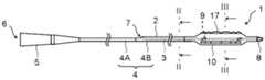
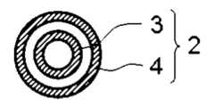
本発明の実施の形態に係るバルーンカテーテル用バルーンと、当該バルーンを備えたバルーンカテーテルの構成例について、図面を参照して説明する。図1~図4には、バルーンカテーテルの構成例を示した。図1は、バルーンカテーテルの側面図を表し、図2は、図1に示したバルーンカテーテルのII-II断面図を表し、図3は、図1に示したバルーンカテーテルのIII-III断面図を表し、図4は、バルーンカテーテルに備えられるバルーンの斜視図の一例を表す。図1にはラピッドエクスチェンジ型のバルーンカテーテルの構成例が示されている。A balloon for a balloon catheter according to an embodiment of the present invention and an example of the configuration of a balloon catheter equipped with the balloon will be described with reference to the drawings. An example of the configuration of a balloon catheter is shown in Figs. 1 to 4. Fig. 1 shows a side view of a balloon catheter, Fig. 2 shows a II-II cross-sectional view of the balloon catheter shown in Fig. 1, Fig. 3 shows a III-III cross-sectional view of the balloon catheter shown in Fig. 1, and Fig. 4 shows an example of a perspective view of a balloon equipped in a balloon catheter. Fig. 1 shows an example of the configuration of a rapid exchange type balloon catheter.
バルーンカテーテル1は、シャフト2と、シャフト2の外側に設けられたバルーン10とを有する。バルーンカテーテル1は近位側と遠位側を有し、シャフト2の遠位部にバルーン10が設けられる。バルーンカテーテル1の近位側とは、バルーンカテーテル1の延在方向に対して使用者(術者)の手元側の方向を指し、遠位側とは近位側の反対方向、すなわち処置対象側の方向を指す。また、バルーンカテーテル1の近位側から遠位側への方向を長手軸方向と称する。The
バルーンカテーテル1は、シャフト2を通じてバルーン10の内部に流体が供給されるように構成され、インデフレーター(バルーン用加減圧器)を用いてバルーン10の拡張および収縮を制御することができる。流体は、ポンプ等により加圧された加圧流体であってもよい。以下、バルーン10の内部に供給される流体を「バルーン拡張流体」と称する。The
シャフト2は、例えば、インナーシャフト3とアウターシャフト4とから構成される。インナーシャフト3はアウターシャフト4の内腔に配置される。インナーシャフト3はシャフト2の進行をガイドするガイドワイヤの挿通路として機能させることができ、バルーンカテーテル1の使用の際、インナーシャフト3の内腔にガイドワイヤが挿通される。インナーシャフト3とアウターシャフト4の間の空間は、バルーン拡張流体の流路として機能させることができる。The
ラピッドエクスチェンジ型のバルーンカテーテル1では、シャフト2の遠位側から近位側に至る途中にガイドワイヤポート7が設けられ、インナーシャフト3の近位端がガイドワイヤポート7に接続し、インナーシャフト3の遠位端がシャフト2の遠位部まで延在することにより、ガイドワイヤポート7からシャフト2の遠位部まで延在するガイドワイヤ挿通路が形成される。In the rapid exchange
アウターシャフト4は近位側アウターシャフト4Aと遠位側アウターシャフト4Bを有していてもよく、この場合、遠位側アウターシャフト4Bの内腔にインナーシャフト3が配置されることが好ましい。近位側アウターシャフト4Aと遠位側アウターシャフト4Bは同じ材料から構成されていてもよく、互いに異なる材料から構成されていてもよい。例えば、近位側アウターシャフト4Aは樹脂または金属から構成され、遠位側アウターシャフト4Bは樹脂から構成されることが好ましい。なお、アウターシャフト4は近位側アウターシャフト4Aと遠位側アウターシャフト4Bに区分されず、1つの部材から構成されていてもよく、近位側アウターシャフト4Aと遠位側アウターシャフト4Bがさらに複数のチューブ部材から構成されていてもよい。The
シャフト2の近位側にはハブ5が設けられることが好ましい。ハブ5は、シャフト2のバルーン拡張流体の流路と連通した流体注入部6を有することが好ましい。バルーン10、シャフト2(インナーシャフト3、アウターシャフト4)、ハブ5の接合は、接着剤や熱溶着など従来公知の接合手段を用いて行うことができる。A
なお、図面に示されていないが、バルーンカテーテルは、インナーシャフトがシャフトの遠位部から近位部まで延び、シャフトの遠位側から近位側にわたってガイドワイヤの挿通路が形成されたオーバーザワイヤ型のバルーンカテーテルであってもよい。この場合、シャフトに設けられたバルーン拡張流体の流路とガイドワイヤの挿通路がハブまで延在し、ハブは、バルーン拡張流体の流路と連通した流体注入部と、ガイドワイヤの挿通路と連通した処置部とを有するように構成されることが好ましい。ハブは二又に分岐した構造を有し、二又に分岐した一方に流体注入部が設けられ、他方に処置部が設けられることが好ましい。Although not shown in the drawings, the balloon catheter may be an over-the-wire type balloon catheter in which the inner shaft extends from the distal to the proximal parts of the shaft and a guidewire passage is formed from the distal to the proximal sides of the shaft. In this case, it is preferable that the flow path of the balloon expansion fluid and the guidewire passage provided in the shaft extend to the hub, and that the hub is configured to have a fluid injection section communicating with the flow path of the balloon expansion fluid and a treatment section communicating with the guidewire passage. It is preferable that the hub has a bifurcated structure, with the fluid injection section provided on one side of the bifurcated branch and the treatment section provided on the other side.
シャフト2の外面はコーティングが施されていることが好ましい。ラピッドエクスチェンジ型のバルーンカテーテル1では、近位側アウターシャフト4Aと遠位側アウターシャフト4Bの一方または両方の外面にコーティングが施されていることが好ましく、近位側アウターシャフト4Aと遠位側アウターシャフト4Bの両方の外面にコーティングが施されていることがより好ましい。オーバーザワイヤ型のバルーンカテーテルでは、アウターシャフトの外面に適宜コーティングが施されていることが好ましい。The outer surface of the
コーティングは、目的に応じて親水性コーティングまたは疎水性コーティングとすることができる。シャフト2を親水性コーティング剤または疎水性コーティング剤に浸漬したり、シャフト2の外面に親水性コーティング剤または疎水性コーティング剤を塗布したり、シャフト2の外面を親水性コーティング剤または疎水性コーティング剤で被覆したりすることにより、シャフト2の外面にコーティングを施すことができる。コーティング剤は、薬剤や添加剤を含んでいてもよい。The coating can be a hydrophilic coating or a hydrophobic coating depending on the purpose. The outer surface of the
親水性コーティング剤としては、ポリビニルアルコール、ポリエチレングリコール、ポリアクリルアミド、ポリビニルピロリドン、メチルビニルエーテル無水マレイン酸共重合体などの親水性ポリマーや、これらが任意の組み合わせで作られた親水性コーティング剤等が挙げられる。Hydrophilic coating agents include hydrophilic polymers such as polyvinyl alcohol, polyethylene glycol, polyacrylamide, polyvinylpyrrolidone, and methyl vinyl ether maleic anhydride copolymers, as well as hydrophilic coating agents made from any combination of these.
疎水性コーティング剤としては、ポリテトラフルオロエチレン(PTFE)、フッ化エチレンプロピレン(FEP)、パーフルオロアルコキシアルカン(PFA)、シリコーンオイル、疎水性ウレタン樹脂、カーボンコート、ダイヤモンドコート、ダイヤモンドライクカーボン(DLC)コート、セラミックコート、アルキル基やパーフルオロアルキル基で終端された表面自由エネルギーが小さい物質等が挙げられる。Hydrophobic coating agents include polytetrafluoroethylene (PTFE), fluorinated ethylene propylene (FEP), perfluoroalkoxyalkane (PFA), silicone oil, hydrophobic urethane resin, carbon coat, diamond coat, diamond-like carbon (DLC) coat, ceramic coat, and substances with low surface free energy terminated with alkyl groups or perfluoroalkyl groups.
バルーンカテーテル1の遠位端部には先端チップ8が設けられていることが好ましい。先端チップ8は、インナーシャフト3の遠位端よりも遠位側にインナーシャフト3とは別部材として設けられてもよく、インナーシャフト3がバルーン10の遠位端よりも遠位側まで延在することにより、インナーシャフト3の遠位端部が先端チップ8として機能してもよい。It is preferable that a
シャフト2には、バルーン10の位置をX線透視下で確認することを可能にするために、長手軸方向に対してバルーン10が位置する部分にX線不透過マーカー9が配置されていてもよい。X線不透過マーカー9は、例えば、バルーン10の内部に配置されたインナーシャフト3上に配置することができ、バルーン10の直管部の両端に相当する位置に配されることが好ましく、バルーン10の直管部の中央に相当する位置に配されてもよい。The
バルーン10は、長手軸方向と径方向を有し、近位側と遠位側に開口を有する筒状に形成されている(図4を参照)。バルーン10の径方向とは、長手軸方向に垂直な方向であって、バルーン10の中心から放射方向に向かって延びる方向を意味する。バルーン10はまた、バルーン10の長手軸方向の垂直断面において、拡張状態のバルーン10の外周に沿った方向として、周方向を有する。The
バルーン10は、長手軸方向に対して、直管部13と、直管部13よりも近位側に位置する近位側テーパー部12と、直管部13よりも遠位側に位置する遠位側テーパー部14とを有する。直管部13は長手軸方向に延びる略円筒形に形成され、バルーン10において径方向の長さ(外径)が最も大きく形成される。近位側テーパー部12は直管部13の近位側に位置し、直管部13の近位端に接続する。近位側テーパー部12は、直管部13から離れるに従って外径が小さくなるように形成されている。遠位側テーパー部14は直管部13の遠位側に位置し、直管部13の遠位端に接続する。遠位側テーパー部14は、直管部13から離れるに従って外径が小さくなるように形成されている。バルーン10はさらに、近位側テーパー部12よりも近位側に位置する近位側スリーブ部11と、遠位側テーパー部14よりも遠位側に位置する遠位側スリーブ部15を有することが好ましい。近位側スリーブ部11は近位側テーパー部12の近位側に位置し、近位側スリーブ部11の近位端に接続する。近位側スリーブ部11は略円筒形に形成されている。遠位側スリーブ部15は遠位側テーパー部14の遠位側に位置し、遠位側スリーブ部15の遠位端に接続する。遠位側スリーブ部15は略円筒形に形成されている。The
上記のようにバルーン10が構成されることにより、バルーン10を狭窄部において拡張させた際に直管部13が狭窄部に十分に接触して、狭窄部の拡張等の治療を行いやすくなる。また、バルーン10が近位側テーパー部12と遠位側テーパー部14を有することにより、バルーン10を収縮させた際にバルーン10の近位端部と遠位端部の外径を小さくしてシャフト2とバルーン10との段差を小さくすることができ、バルーン10を体腔内や内視鏡の鉗子チャネル内、ガイディングカテーテルなどのデリバリー用のカテーテル内に挿通させやすくすることができる。By configuring the
シャフト2の遠位部において、インナーシャフト3はアウターシャフト4の遠位端より遠位側に延出し、インナーシャフト3がバルーン10の内部空間を近位側スリーブ部11から遠位側スリーブ部15にかけて延在することが好ましい。そして、インナーシャフト3の外面がバルーン10の遠位側スリーブ部15の内面に接合し、アウターシャフト4の外面がバルーン10の近位側スリーブ部11の内面に接合することが好ましい。このようにシャフト2の遠位部が構成されることにより、バルーン拡張流体を、インナーシャフト3とアウターシャフト4の間の空間を通ってバルーン10の内部空間に供給することができる。At the distal portion of the
バルーン10の大きさは特に限定されない。バルーン10の大きさは、例えば、直管部13の長手軸方向の長さが4mm~400mm、直管部13の外径が1mm~30mmの範囲で適宜設定することができる。The size of the
バルーン10(特にバルーン本体部16)は樹脂から構成されることが好ましく、より好ましくは熱可塑性樹脂から構成される。これにより、成型によりバルーン10を製造することが容易になる。バルーン10を構成する樹脂としては、例えば、ポリエチレン、ポリプロピレン、エチレン-プロピレン共重合体等のポリオレフィン樹脂、ポリエチレンテレフタレート、ポリエステルエラストマー等のポリエステル樹脂、ポリウレタン、ポリウレタンエラストマー等のポリウレタン樹脂、ポリフェニレンサルファイド樹脂、ポリアミド、ポリアミドエラストマー等のポリアミド樹脂、フッ素系樹脂、シリコーン樹脂、ラテックスゴム等の天然ゴム等が挙げられる。これらは1種のみを用いてもよく、2種以上を併用してもよい。なかでも、ポリアミド樹脂、ポリエステル樹脂、ポリウレタン樹脂が好適に用いられる。特に、バルーン10の薄膜化や柔軟性の点から、エラストマー樹脂を用いることが好ましい。例えばポリアミド樹脂の中でバルーン10に好適な材料として、ナイロン12、ナイロン11等が挙げられ、ブロー成形する際に比較的容易に成形可能である点から、ナイロン12が好適に用いられる。また、バルーン10の薄膜化や柔軟性の点から、ポリエーテルエステルアミドエラストマー、ポリアミドエーテルエラストマー等のポリアミドエラストマーが好ましく用いられる。なかでも、降伏強度が高く、バルーン10の寸法安定性が良好な点から、ポリエーテルエステルアミドエラストマーが好ましく用いられる。The balloon 10 (particularly the balloon body 16) is preferably made of a resin, more preferably a thermoplastic resin. This makes it easier to manufacture the
バルーン10は、直管部13の外面に凸条17を有する。直管部13の外面に凸条17が設けられることにより、バルーン10はスコアリング機能を有するものとなり、バルーン10を血管の狭窄部において拡張させた際に、石灰化した狭窄部に食い込んで、狭窄部に亀裂を入れたりすることが可能となる。そのため、血管内膜の解離を抑えながら狭窄部を拡張させることができる。また、バルーン10の高耐圧化や加圧時の過拡張の抑制も可能となる。なお、バルーン10は、血管以外の体腔の狭窄部や病変部の治療に用いることもできるが、以下ではバルーン10を血管治療に適用する場合を中心に説明する。The
バルーン10の凸条17について、図5および図6を参照して詳しく説明する。図5には、バルーン10の直管部13の長手軸方向の垂直断面図が示され、図6には、バルーン10の凸条17の拡大断面図が示されている。図5には、図4に示したバルーン10の直管部13の長手軸方向の垂直断面における構成例が示されており、凸条17が直管部13の周方向の3箇所に設けられている。The
バルーン10の直管部13は、筒形状のバルーン本体部16を有し、バルーン本体部16の外面に凸条17が設けられる。凸条17は、バルーン本体部16の外面から径方向の外方に突出するように設けられる。バルーン10は、凸条17が設けられることにより、直管部13の外面に凸条存在領域24と凸条非存在領域25が形成される。なお、凸条存在領域24には、後述するように、凸条17において切欠き19が形成された部分も含まれる。直管部13の外面は凸条非存在領域25において平坦に形成されることが好ましく、例えば、凸条非存在領域25の一部において直管部13の外面が窪んで形成されたりしないことが好ましい。これにより、バルーン10を均等に拡張させることが容易になり、凸条17によるスコアリング機能を所望の通り発揮させやすくなる。なお、直管部13の外面が凸条非存在領域25において平坦に形成されるとは、凸条非存在領域25が平面をアーチ状にたわませた形状となり、アーチ状にたわんだ平面において凹凸が形成されないことを意味する。当該凹凸には、製造上不可避的に形成される表面粗さは含まれない。The
凸条17は、頂部17Aと基部17Bを有する。凸条17において、頂部17Aは凸条17の先端、すなわち凸条17の径方向の最も外方に位置する部分を意味し、基部17Bは、バルーン本体部16との境界、すなわち凸条17の径方向の最も内方に位置する部分を意味する。The
凸条17は、例えば樹脂から構成することができる。凸条17が樹脂から構成されていれば、凸条17を有するバルーン10を樹脂成型により製造することができ、製造が容易になる。この場合、凸条17とバルーン本体部16は同じ樹脂から構成されることが好ましく、凸条17とバルーン本体部16とが一体成形されていることが好ましい。バルーン本体部16は内層と外層を有していてもよく、この場合、凸条17はバルーン本体部16の外層と同じ樹脂から構成されていることが好ましい。これにより、凸条17が意図せずバルーン本体部16から脱落することが起こりにくくなる。あるいは、凸条17を構成する樹脂とバルーン本体部16を構成する樹脂とがある程度の相溶性があれば、凸条17とバルーン本体部16は互いに異なる樹脂から構成されていてもよい。The
凸条17は金属から構成されてもよく、あるいは金属と樹脂の組み合わせから構成されてもよい。この場合、凸条17の頂部17Aを含む部分が金属から構成されることが好ましい。これにより、バルーン10を拡張させた際に、凸条17によって狭窄部に亀裂を入れたり、狭窄部を切開することが容易になる。例えば、凸条17の全体が金属から構成されてもよく、凸条17の基部17Bを含む部分が樹脂から構成され、凸条17の頂部17Aを含む部分が金属から構成されてもよい。従って、凸条17は、樹脂製、金属製、またはその組み合わせであることが好ましい。The
直管部13において、バルーン本体部16は筒形状を有する部分として規定される。直管部13において径方向の外方に突出した凸条17を除いた部分がバルーン本体部16となる。バルーン本体部16は外面が円筒形に形成されていると見なすことができる。従って、直管部13の長手軸方向の垂直断面において、バルーン本体部16の外形は実質的に円形に形成され、これによりバルーン本体部16と凸条17とを区分することができる。凸条存在領域24はバルーン本体部16と凸条17とから構成され、凸条非存在領域25はバルーン本体部16から構成される。In the
凸条17は、直管部13の外面において、畝状に延びるように設けられる。凸条17はバルーン10の長手軸方向に略平行に延びている。凸条17は、バルーン10の直管部13において、周方向の異なる位置に複数設けられる。すなわち凸条17は、バルーン10の周方向の複数箇所に設けられる。この場合、凸条17は、バルーン10の直管部13の周方向に略等間隔に配置されることが好ましい。これにより、バルーン10を拡張させた際に、狭窄部の複数の箇所に亀裂を入れることが可能となる。凸条17は、バルーン10の周方向に対して2箇所以上の位置に設けられることが好ましく、3箇所以上がより好ましく、また12箇所以下が好ましく、10箇所以下がより好ましく、8箇所以下がさらに好ましい。また、この場合の凸条17の周方向の間隔は、1つの凸条17の周方向の長さよりも長いことが好ましい。The
複数の凸条17は、長手軸方向に略同位置に設けられることが好ましい。すなわち、複数の凸条17の近位端は長手軸方向に互いに略同位置にあることが好ましく、複数の凸条17の遠位端は長手軸方向に互いに略同位置にあることが好ましい。It is preferable that the
凸条17の断面形状は特に限定されない。例えば、直管部13の長手軸方向の垂直断面における凸条17の形状としては、三角形、四角形等の多角形、半円形、扇形等の円形の部分形状、楔型、凸形、紡錘形、不定形等が挙げられる。多角形には、角部の頂点が明確であって辺が直線であるものの他に、角部が丸みを帯びている角丸多角形や、辺の少なくとも一部が曲線となっているものも含まれる。なお、凸条17は、頂部17Aに向かって幅が漸減するように形成されることが好ましい。The cross-sectional shape of the
直管部13の長手軸方向の垂直断面において、凸条17の高さは凸条17の幅(最大幅)の0.2倍以上であることが好ましい。このように凸条17が形成されていれば、狭窄部においてバルーン10を拡張させた際に、凸条17が狭窄部に食い込みやすくなり、凸条17によるスコアリング機能を高めることができる。なお、ここで説明した凸条17の幅は、凸条17の周方向の長さを意味する。凸条17は、基部17Bにおいて最大幅となるように形成されていることが好ましく、これにより凸条17がバルーン本体部16の外面に安定して設置される。凸条17の高さは凸条17の幅の0.4倍以上がより好ましく、0.7倍以上がさらに好ましい。一方、凸条17の高さは凸条17の幅の2.0倍以下が好ましく、1.8倍以下がより好ましく、1.5倍以下がさらに好ましい。これにより、凸条17が存在する部分でバルーン10の屈曲性を確保しやすくなる。In a vertical cross section in the longitudinal direction of the
直管部13において、凸条17が設けられた部分の肉厚、すなわち凸条存在領域24の肉厚は、凸条17が設けられない部分の肉厚、すなわち凸条非存在領域25の肉厚よりも厚く形成されていることが好ましい。これにより、凸条17によるスコアリング機能を高めることができる。凸条存在領域24の肉厚(最大肉厚)は、凸条非存在領域25の肉厚(最大肉厚)の1.5倍以上であることが好ましく、2.0倍以上がより好ましく、2.5倍以上がさらに好ましい。凸条存在領域24の肉厚の上限は特に限定されず、例えば、凸条非存在領域25の肉厚の30倍以下、20倍以下または10倍以下であってもよい。In the
バルーン10において、凸条17は、直管部13の長手軸方向の60%以上の範囲に設けられることが好ましく、70%以上の範囲がより好ましく、80%以上の範囲がさらに好ましい。これにより、バルーン10を拡張させた際に、狭窄部の広い範囲に亀裂を入れることが可能となる。凸条17は、直管部13の長手軸方向の90%以上の範囲に設けられてもよく、直管部13の長手軸方向のほぼ全体にわたって設けられてもよく、さらに近位側テーパー部12および/または遠位側テーパー部14の外面にも設けられてもよい。In the
バルーン10は、バルーン10の内面において径方向の内方に向かって突出している内側凸条を有していてもよい(図示せず)。凸条17と内側凸条はバルーン10の長手軸方向や周方向に対して同じ位置に配置されていてもよく、これらは一体成形されていることが好ましく、これによりバルーン10の一部が肉厚に形成されていてもよい。The
凸条17が設けられたバルーン10は、凸条17が設けられた部分で剛性が高くなる傾向を示す。そのため、凸条17が設けられたバルーン10は、凸条17が設けられないバルーン10と比較して、長手軸方向の屈曲性が低下しやすくなる。例えば、血液透析の際に形成されるシャントでは、動静脈吻合部で血管が大きく屈曲するが、そのような箇所にバルーンを挿通させる場合、凸条が設けられたバルーンを動静脈吻合部に挿通させることが難しくなるおそれがある。あるいは、下肢用のバルーンでは、治療の際に腸骨動脈にバルーンを挿通させたりするが、左右の腸骨動脈が腹部大動脈から分岐する分岐部では血管が大きく屈曲している。そのため、下肢用のバルーンに凸条が設けられる場合、バルーンを左右の腸骨動脈の一方から他方に挿通させることが難しくなるおそれがある。特に、下肢用のバルーンは長さが長いため、血管が大きく屈曲した箇所をバルーンが通過できなくなるおそれが高くなる。そこで、図4に示すように、バルーン10には、凸条17に切欠き19が形成されている。凸条17に切欠き19が形成されることにより、バルーン10の長手軸方向の屈曲性を高めることができる。The
切欠き19は各凸条17に形成されることが好ましい。これにより、バルーン10が屈曲する方向に関わらず、バルーン10の屈曲性を高めることができる。It is preferable that the
各凸条17に形成される切欠き19の数は1以上であれば特に限定されないが、バルーン10の屈曲性を高める観点から、各凸条17に形成される切欠き19の数は2以上が好ましく、3以上がより好ましい。一方、バルーン10のスコアリング機能を確保する点から、各凸条17に形成される切欠き19の数は20以下が好ましく、16以下がより好ましく、12以下がさらに好ましく、8以下がさらにより好ましい。The number of
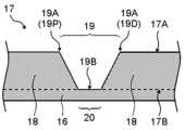
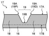
切欠き19は、長手軸方向に延在する凸条17の頂部17Aの一部が切除されるように形成されればよい。図7~図10には、切欠き19の様々な形成例が示され、凸条17および切欠き19について、凸条17の頂部17Aを通る長手軸方向に沿った断面図が示されている。図8に示すように、切欠き19は、凸条17の頂部17Aから基部17Bまで延びるように形成されてもよく、図7、図9および図10に示すように、切欠き19は、凸条17の頂部17Aから基部17Bに至る途中まで延びるように形成されてもよい。前者の場合、切欠き19の深さは凸条17の高さに一致する。後者の場合、切欠き19の深さは凸条17の高さよりも短く形成される。The
切欠き19は底部19Bと頂部19Aを有し、底部19Bは切欠き19の径方向の最も内方に位置する部分を意味し、頂部19Aは切欠き19の径方向の最も外方に位置する部分を意味する。切欠き19の頂部19Aは、切欠き19の近位端19Pと遠位端19Dに相当し、凸条17の頂部17Aと一致する。切欠き19の頂部19Aから底部19Bまでの径方向の長さが、切欠き19の深さとなる。The
凸条17は、切欠き19によって複数の凸条セグメント18に区分される。図8に示すように、切欠き19が凸条17の頂部17Aから基部17Bまで延びるように形成される場合は、切欠き19によって凸条17の途切れ部20が形成され、途切れ部20の近位側および遠位側に凸条セグメント18が配置されることとなる。途切れ部20は長手軸方向に所定の長さを有し、凸条17は、凸条セグメント18と途切れ部20が長手軸方向に交互に配置されることにより形成される。切欠き19が凸条17の頂部17Aから基部17Bに至る途中まで延びるように形成される場合は、切欠き19の底部19Bを境界として、それより近位側の凸条セグメント18とそれより遠位側の凸条セグメント18に区分される。The
切欠き19の形状は特に限定されない。切欠き19は例えば、凸条17の頂部17Aを通る長手軸方向に沿った断面において、図7に示すようにV字状に形成されたり、図9に示すようにU字状に形成されたり、図8および図10に示すように矩形の一辺を除いた形状で形成されてもよい。なお、切欠き19の外縁は、凸条17の頂部17Aを通る長手軸方向に沿った断面において、径方向の外方に向かって近位側に傾斜して延びる部分と、当該部分よりも遠位側に、径方向の外方に向かって遠位側に傾斜して延びる部分を有することが好ましい。切欠き19の外縁の近位側または遠位側に傾斜して延びる部分は、直線状に傾斜して延びてもよく、曲線状に傾斜して延びてもよく、それらが組み合わされたものであってもよい。より好ましくは、切欠き19の近位側の外縁の全体が、切欠き19の底部19Bから径方向の外方に向かって近位側に傾斜して延びるように形成され、切欠き19の遠位側の外縁の全体が、切欠き19の底部19Bから径方向の外方に向かって遠位側に傾斜して延びるように形成される。以下、切欠き19の長さや形状に関して詳しく説明するが、これらは凸条17の頂部17Aを通る長手軸方向に沿った断面における切欠き19の長さや形状に基づき定められる。The shape of the
切欠き19の長手軸方向の長さは、凸条セグメント18の長手軸方向の長さよりも短いことが好ましい。具体的には、各凸条17において、切欠き19の長手軸方向の長さ(切欠き19が複数設けられる場合は、各切欠き19の長手軸方向の長さ)は、いずれの凸条セグメント18の長手軸方向の長さよりも短いことが好ましい。また、各凸条17において、切欠き19の長手軸方向の長さ(切欠き19が複数設けられる場合は、各切欠き19の長手軸方向の長さ)は、凸条セグメント18の長手軸方向の長さの平均値の0.5倍以下が好ましく、0.3倍以下がより好ましく、0.2倍以下がさらに好ましい。これにより、凸条17によるスコアリング機能を確保することが容易になる。なお、切欠き19の長手軸方向の長さは、切欠き19を挟んで近位側と遠位側にある凸条セグメント18の頂部間距離、すなわち切欠き19を挟んで近位側にある凸条セグメント18の頂部の遠位端と遠位側にある凸条セグメント18の頂部の近位端との間の距離を意味する。The length of the
各凸条17において、切欠き19の長手軸方向の長さの合計は、凸条17の長手軸方向の長さの20%以下であることが好ましく、15%以下がより好ましく、10%以下がさらに好ましい。これにより、凸条17によるスコアリング機能を確保することが容易になる。凸条17の長手軸方向の長さは次のように定められる。各凸条17を構成する複数の凸条セグメント18のうち、最も近位側にある凸条セグメント18の近位端が凸条17の近位端となり、最も遠位側にある凸条セグメント18の遠位端が凸条17の遠位端となり、凸条17の近位端から遠位端までの長手軸方向の長さが、凸条17の長手軸方向の長さとなる。In each
各切欠き19において、切欠き19の長手軸方向の長さは、切欠き19の深さの0.2倍以上が好ましく、0.3倍以上がより好ましく、0.5倍以上がさらに好ましい。これにより、バルーン10の直管部13の長手軸方向への屈曲性を高めることが容易になる。各切欠き19において、切欠き19の長手軸方向の長さは、切欠き19の深さの5倍以下が好ましく、3倍以下がより好ましく、2倍以下がさらに好ましい。これにより、バルーン10のスコアリング機能を確保することが容易になる。For each
切欠き19の底部19Bが長手軸方向に平行に延びる部分の長さは、切欠き19の長手軸方向の長さ(切欠き19を挟んで近位側と遠位側にある凸条セグメント18の頂部間距離)と比べて、あまり長く形成されないことが好ましい(図8および図10を参照)。各切欠き19において、切欠き19の底部19Bが長手軸方向に平行に延びる部分の長さは、切欠き19の長手軸方向の長さの0.5倍以下が好ましく、0.3倍以下がより好ましく、0.2倍以下がさらに好ましい。これにより、バルーン10が切欠き19でスムーズに屈曲しやすくなるとともに、凸条17によるスコアリング機能を確保することが容易になる。切欠き19の底部19Bは長手軸方向に平行に延びる部分が含まれなくてもよい。なお、切欠き19が凸条17の頂部17Aから基部17Bまで延びるように形成される場合、凸条17の途切れ部20の長手軸方向の長さ(バルーン本体部16の外面における途切れ部20の長手軸方向の長さ)が切欠き19の底部19Bの長手軸方向の長さに相当する。It is preferable that the length of the portion of the bottom 19B of the
図4に示すように、各凸条17には、凸条17の近位側の部分と遠位側の部分に多くの数の切欠き19が設けられている。具体的には、各凸条17において、凸条17を長手軸方向に3等分し近位区間21、中間区間22、遠位区間23に区分したとき、近位区間21に設けられた切欠き19の数と遠位区間23に設けられた切欠き19の数がそれぞれ、中間区間22に設けられた切欠き19の数よりも多くなるように、切欠き19が設けられている。このように凸条17に切欠き19が設けられることにより、バルーン10の屈曲性を高めることができる。また、凸条17の中間区間22のスコアリング機能を確保することが容易になる。As shown in FIG. 4, each
血管の屈曲部にバルーン10を挿通させる場合、バルーン10の近位部と遠位部(具体的には、バルーン10において、長手軸方向に対して凸条17の近位区間21と遠位区間23に対応する部分)の屈曲性が重要になる。例えばバルーン10を押し込んで血管の屈曲部に挿通させる場合、バルーン10の遠位部を挿通させることができなければ、それよりも近位側の部分も当該屈曲部に挿通させることができず、バルーン10による治療そのものを行うことができない。バルーン10を引き戻して屈曲部に挿通させる場合は、バルーン10の近位部を挿通させることができなければ、それよりも遠位側の部分も当該屈曲部に挿通させることができず、バルーン10を体内から引き抜くことができない。この場合、無理に血管の屈曲部に通そうとバルーン10を押し込んだり引き戻したりすると、血管を損傷するおそれが高まる。しかし、上記のように各凸条17に切欠き19が設けられていれば、バルーン10を押し込んだり引き戻したりして屈曲部に挿通させる場合に、バルーン10を屈曲部に挿通させることが容易になる。一方、各凸条17の中間区間22には切欠き19が設けられないか、近位区間21と遠位区間23よりも少ない数の切欠き19が設けられるため、凸条17によるスコアリング機能を高めることができる。When the
各凸条17の近位区間21、中間区間22、遠位区間23は次のように定められる。凸条17の近位端から遠位端までの長手軸方向の長さをLとしたとき、凸条17をL/3の長さで3つに区分し、最も近位側の区間を近位区間21、最も遠位側の区間を遠位区間23、近位区間21と遠位区間23の間の区間を中間区間22と定める。凸条17における切欠き19の長手軸方向の位置、すなわち切欠き19が凸条17の近位区間21、中間区間22、遠位区間23のいずれに位置するかの判断は、凸条17の頂部17Aを通る長手軸方向に沿った断面における切欠き19の底部19Bの位置に基づき決められる。切欠き19の底部19Bが長手軸方向に所定の長さで形成される場合は、切欠き19の底部19Bの長手軸方向の中点を、凸条17における切欠き19の長手軸方向の位置とする。切欠き19の底部19Bが近位区間21と中間区間22の境界または中間区間22と遠位区間23の境界にちょうど位置する場合は、両方の区間に存在するが、どちらの区間にも数えない。The
上記のように各凸条17に切欠き19が設けられる場合、切欠き19は凸条17の近位区間21と遠位区間23に必須的に設けられ、凸条17の中間区間22には切欠き19が設けられても設けられなくてもよい。例えば、凸条17の中間区間22に切欠き19が設けられていなければ、凸条17によるスコアリング機能を高めることができる。When a
凸条17の遠位区間23には、次のように切欠き19が設けられることが好ましい。すなわち、遠位区間23を長手軸方向に2等分し遠位側から第1遠位区間23Aと第2遠位区間23Bとしたとき、少なくとも第1遠位区間23Aに切欠き19が設けられることが好ましい。このように切欠き19が設けられることにより、バルーン10を押し込んで屈曲部に挿通させることが容易になる。遠位区間23には2以上の切欠き19が設けられてもよく、3以上の切欠き19が設けられてもよい。It is preferable that the
遠位区間23には、第1遠位区間23Aと第2遠位区間23Bの両方に切欠き19が設けられてもよい。この場合、第1遠位区間23Aに設けられた切欠き19の数が第2遠位区間23Bに設けられた切欠き19の数と同じかそれよりも多くなるように、切欠き19が設けられることが好ましい。これにより、バルーン10を押し込んで屈曲部に挿入する際の挿入性をより高めることができる。The
凸条17の近位区間21には、次のように切欠き19が設けられることが好ましい。すなわち、近位区間21を長手軸方向に2等分し近位側から第1近位区間21Aと第2近位区間21Bとしたとき、少なくとも第1近位区間21Aに切欠き19が設けられることが好ましい。このように切欠き19が設けられることにより、バルーン10を引き戻して屈曲部に挿通させることが容易になる。近位区間21には2以上の切欠き19が設けられてもよく、3以上の切欠き19が設けられてもよい。It is preferable that the
近位区間21には、第1近位区間21Aと第2近位区間21Bの両方に切欠き19が設けられてもよい。この場合、第1近位区間21Aに設けられた切欠き19の数が第2近位区間21Bに設けられた切欠き19の数と同じかそれよりも多くなるように、切欠き19が設けられることが好ましい。これにより、バルーン10を引き戻して屈曲部に挿入する際の挿入性をより高めることができる。The
実施形態の一つとして、各凸条17の中間区間22には切欠き19が設けられなくてもよい。このように凸条17が形成されていれば、バルーン10の屈曲性を高めつつ、バルーン10に高いスコアリング機能を付与することが容易になる。一方、バルーン10の屈曲性をより高めるために、凸条17の中間区間22にも切欠き19を設けてもよい。例えば、下肢用のバルーン10は長手軸方向の長さが長いため、中間区間22にも切欠き19を設けることにより、長手軸方向の長さが長いバルーン10においても、バルーン10の長手軸方向の全体にわたって屈曲性を確保することができる。As one embodiment, the
各凸条17は、長手軸方向に隣接する凸条セグメント18の長手軸方向の長さが互いに同じか、長手軸方向の中央側に位置する凸条セグメント18の方が長く形成されていてもよい。この場合、各凸条17に存在する全ての凸条セグメント18が、このように形成されていることが好ましい。このように凸条17が形成されていれば、バルーン10を押し込んで屈曲部に挿通させたりバルーン10を引き戻して屈曲部に挿通させる際に、バルーン10を屈曲部に挿通させることが容易になる。Each
各凸条17に切欠き19が複数設けられる場合、複数の切欠き19の深さは互いに同じであっても異なっていてもよい。実施形態の一つとして、凸条17には次のように切欠き19が設けられてもよい。すなわち、凸条17は、遠位区間23に設けられた切欠き19の最も深い深さが、中間区間22に設けられた切欠き19の最も深い深さよりも深く形成されてもよい。これによりバルーン10の遠位部の屈曲性をさらに高めることができ、バルーン10を押し込んで屈曲部に挿通させることが容易になる。また、凸条17は、遠位区間23に設けられた切欠き19の最も深い深さと近位区間21に設けられた切欠き19の最も深い深さが、中間区間22に設けられた切欠き19の最も深い深さよりも深く形成されてもよい。これにより、バルーン10の遠位部と近位部の屈曲性をさらに高めることができ、バルーン10を押し込んで屈曲部に挿通させる場合も、バルーン10を引いて屈曲部に挿通させる場合も、バルーン10を屈曲部に挿通させることが容易になる。When
上記とは逆に、凸条17には次のように切欠き19が設けられてもよい。すなわち、凸条17は、中間区間22に設けられた切欠き19の最も深い深さが、遠位区間23に設けられた切欠き19の最も深い深さよりも深く形成されてもよい。また、凸条17は、中間区間22に設けられた切欠き19の最も深い深さが、遠位区間23に設けられた切欠き19の最も深い深さと近位区間21に設けられた切欠き19の最も深い深さよりも深く形成されてもよい。このように凸条17に切欠き19が設けられていれば、中間区間22に設ける切欠き19の数を少なくしつつ、中間区間22における屈曲性を高めることができる。そのため、凸条17によるスコアリング機能を確保しつつ、バルーン10の長手軸方向の全体にわたって屈曲性を確保しやすくなる。Conversely, the
バルーン10の直管部13の長手軸方向の長さは、例えば4mm以上、10mm以上、20mm以上または30mm以上であってもよいが、凸条17が設けられたバルーン10は、長手軸方向の長さが長いほど屈曲部を挿通させにくくなる。従って、凸条17に切欠き19を設けることの効果がより奏効される点から、バルーン10の直管部13の長手軸方向の長さは50mm以上であることが好ましく、60mm以上がより好ましく、80mm以上がさらに好ましい。The length in the longitudinal direction of the
図11に示すように、凸条17は、直管部13の長手軸方向の垂直断面において、基部17Bから頂部17Aに向かって段状に幅が狭まるように形成され、段状に形成された凸条17の頂部17A側の部分のみに切欠き19が形成されてもよい。例えば、凸条17は、バルーン本体部16の外面に隣接した第1段部分26と、それよりも頂部17A側の第2段部分27を有し、切欠き19が第2段部分27に形成され、第1段部分26に形成されなくてもよい。第1段部分26と第2段部分27は同じ材料から構成されていてもよく、互いに異なる材料から構成されていてもよい。例えば、第1段部分26と第2段部分27がともに樹脂から構成されたり、第1段部分26が金属から構成され、第2段部分27が樹脂から構成されてもよい。As shown in FIG. 11, the
バルーン10の直管部13の外面には薬剤が保持されていてもよい。薬剤は、薬理活性物質であれば特に限定されず、例えば、遺伝子治療薬、非遺伝子治療薬、小分子、細胞等の医薬として許容される薬剤が挙げられる。特に、カテーテルを血管形成術における治療後の血管の再狭窄を抑制する目的で使用する場合は、薬剤として抗増殖剤や免疫抑制剤などの抗再狭窄剤を好ましく用いることができる。このような薬剤としては、例えば、パクリタキセル、シロリムス(ラパマイシン)、エベロリムス、ゾタロリムス等が挙げられる。A drug may be retained on the outer surface of the
1:バルーンカテーテル
2:シャフト
3:インナーシャフト
4:アウターシャフト、4A:近位側アウターシャフト、4B:遠位側アウターシャフト
5:ハブ
6:流体注入部
7:ガイドワイヤポート
8:先端チップ
9:X線不透過マーカー
10:バルーン
11:近位側スリーブ部
12:近位側テーパー部
13:直管部
14:遠位側テーパー部
15:遠位側スリーブ部
16:バルーン本体部
17:凸条、17A:頂部、17B:基部
18:凸条セグメント
19:切欠き、19A:頂部、19B:底部、19P:近位端、19D:遠位端
20:途切れ部
21:近位区間、21A:第1近位区間、21B:第2近位区間
22:中間区間
23:遠位区間、23A:第1遠位区間、23B:第2遠位区間
24:凸条存在領域
25:凸条非存在領域
26:第1段部分
27:第2段部分 1: Balloon catheter 2: Shaft 3: Inner shaft 4: Outer shaft, 4A: Proximal outer shaft, 4B: Distal outer shaft 5: Hub 6: Fluid injection section 7: Guidewire port 8: Distal tip 9: X-ray opaque marker 10: Balloon 11: Proximal sleeve section 12: Proximal tapered section 13: Straight tube section 14: Distal tapered section 15: Distal sleeve section 16: Balloon body section 17: Convex strip, 17A: Apex, 17B: Base 18: Convex strip segment 19: Notch, 19A: Apex, 19B: Bottom, 19P: Proximal end, 19D: Distal end 20: Discontinued section 21: Proximal section, 21A: First proximal section, 21B: Second proximal section 22: Intermediate section 23: Distal section, 23A: First distal section, 23B: Second distal section, 24: Region with ridges, 25: Region without ridges, 26: First step portion, 27: Second step portion
Claims (8)
Translated fromJapanese前記バルーンは、直管部と、前記直管部よりも近位側に位置する近位側テーパー部と、前記直管部よりも遠位側に位置する遠位側テーパー部とを有し、
前記直管部は、筒形状のバルーン本体部と、前記バルーン本体部の外面に、径方向の外方に突出し長手軸方向に延びる凸条とを有し、前記凸条は前記直管部の周方向に複数設けられ、
前記各凸条には切欠きが形成されており、
前記各凸条において、前記凸条を長手軸方向に3等分し近位区間、中間区間、遠位区間に区分したとき、前記近位区間に設けられた前記切欠きの数と前記遠位区間に設けられた前記切欠きの数はそれぞれ、前記中間区間に設けられた前記切欠きの数よりも多いバルーンカテーテル用バルーン。 A balloon for a balloon catheter having a longitudinal axis direction extending from a proximal side to a distal side, and a radial direction and a circumferential direction perpendicular to the longitudinal axis direction,
The balloon has a straight tube portion, a proximal tapered portion located proximally of the straight tube portion, and a distal tapered portion located distally of the straight tube portion,
The straight pipe portion has a cylindrical balloon main body and a protrusion on an outer surface of the balloon main body that protrudes radially outward and extends in a longitudinal axis direction, and the protrusion is provided in a plurality of circumferential directions of the straight pipe portion.
Each of the protrusions has a notch formed therein,
When each of the ridges is divided into thirds in the longitudinal direction into a proximal section, an intermediate section, and a distal section, the number of the notches provided in the proximal section and the number of the notches provided in the distal section are each greater than the number of the notches provided in the intermediate section.
前記遠位区間を長手軸方向に2等分し遠位側から第1遠位区間と第2遠位区間としたとき、少なくとも前記第1遠位区間に前記切欠きが設けられている請求項1に記載のバルーン。 When the proximal section is divided into two equal parts in the longitudinal axis direction into a first proximal section and a second proximal section from the proximal side, the notch is provided in at least the first proximal section, and/or
The balloon according to claim 1 , wherein when the distal section is divided into two equal parts in the longitudinal direction into a first distal section and a second distal section from the distal side, the notch is provided in at least the first distal section.
前記各凸条において、長手軸方向に隣接する前記凸条セグメントの長手軸方向の長さは、互いに同じか、長手軸方向の中央側に位置する前記凸条セグメントの方が長い請求項1に記載のバルーン。 Each of the ridges has a plurality of ridge segments divided by the notches,
The balloon according to claim 1, wherein the longitudinal lengths of the adjacent ridge segments in each ridge are equal to each other or the ridge segment located toward the center in the longitudinal direction is longer.
Priority Applications (2)
| Application Number | Priority Date | Filing Date | Title |
|---|---|---|---|
| JP2023065586AJP2024151845A (en) | 2023-04-13 | 2023-04-13 | Balloon for balloon catheter and balloon catheter |
| CN202410362441.XACN118787840A (en) | 2023-04-13 | 2024-03-28 | Balloon for balloon catheter and balloon catheter |
Applications Claiming Priority (1)
| Application Number | Priority Date | Filing Date | Title |
|---|---|---|---|
| JP2023065586AJP2024151845A (en) | 2023-04-13 | 2023-04-13 | Balloon for balloon catheter and balloon catheter |
Publications (1)
| Publication Number | Publication Date |
|---|---|
| JP2024151845Atrue JP2024151845A (en) | 2024-10-25 |
Family
ID=93030490
Family Applications (1)
| Application Number | Title | Priority Date | Filing Date |
|---|---|---|---|
| JP2023065586APendingJP2024151845A (en) | 2023-04-13 | 2023-04-13 | Balloon for balloon catheter and balloon catheter |
Country Status (2)
| Country | Link |
|---|---|
| JP (1) | JP2024151845A (en) |
| CN (1) | CN118787840A (en) |
Cited By (1)
| Publication number | Priority date | Publication date | Assignee | Title |
|---|---|---|---|---|
| CN120360644A (en)* | 2025-06-27 | 2025-07-25 | 浙江归创医疗科技有限公司 | Serrated balloon |
- 2023
- 2023-04-13JPJP2023065586Apatent/JP2024151845A/enactivePending
- 2024
- 2024-03-28CNCN202410362441.XApatent/CN118787840A/enactivePending
Cited By (1)
| Publication number | Priority date | Publication date | Assignee | Title |
|---|---|---|---|---|
| CN120360644A (en)* | 2025-06-27 | 2025-07-25 | 浙江归创医疗科技有限公司 | Serrated balloon |
Also Published As
| Publication number | Publication date |
|---|---|
| CN118787840A (en) | 2024-10-18 |
Similar Documents
| Publication | Publication Date | Title |
|---|---|---|
| JP2024151845A (en) | Balloon for balloon catheter and balloon catheter | |
| WO2024214552A1 (en) | Balloon catheter-use balloon, and balloon catheter | |
| JP2024151846A (en) | Balloon for balloon catheter and balloon catheter | |
| WO2024214553A1 (en) | Balloon for balloon catheter, and balloon catheter | |
| JP2024151848A (en) | Balloon for balloon catheter and balloon catheter | |
| JP2025007550A (en) | Balloon for balloon catheter and balloon catheter | |
| JP2025007551A (en) | Balloon for balloon catheter and balloon catheter | |
| JP2024151847A (en) | Balloon for balloon catheter and balloon catheter | |
| JP2024072607A (en) | Balloon for balloon catheter, balloon catheter including same, and method for manufacturing balloon catheter | |
| WO2023080063A1 (en) | Balloon for balloon catheter | |
| WO2025009449A1 (en) | Balloon for balloon catheter and balloon catheter | |
| JP2024171866A (en) | Balloon for balloon catheter and balloon catheter equipped with same | |
| WO2024247745A1 (en) | Balloon for balloon catheters and balloon catheter provided therewith | |
| JP2025073657A (en) | Balloon for balloon catheter and balloon catheter equipped with same | |
| JP2024171867A (en) | Balloon for balloon catheter and balloon catheter equipped with same | |
| JP2025073658A (en) | A balloon for a balloon catheter and a balloon catheter including the same. | |
| JP2024140204A (en) | Balloon for balloon catheter, balloon catheter including same, and method for manufacturing balloon catheter | |
| JP2024140203A (en) | Balloon for balloon catheter, balloon catheter including same, and method for manufacturing balloon catheter | |
| WO2024106084A1 (en) | Balloon for balloon catheter and balloon catheter | |
| JP2024072606A (en) | Balloon for balloon catheter, balloon catheter including same, and method for manufacturing balloon catheter | |
| WO2024106083A1 (en) | Balloon for balloon catheter, and balloon catheter | |
| WO2024106176A1 (en) | Balloon for balloon-catheter, balloon catheter equipped with same, and method for manufacturing balloon catheter | |
| WO2025159018A1 (en) | Balloon for balloon catheter and balloon catheter | |
| US20250269153A1 (en) | Balloon for balloon catheter, balloon catheter including same, and method for producing balloon catheter | |
| WO2025159019A1 (en) | Balloon for balloon catheter and balloon catheter |