JP2024147269A - Pulse oximeter - Google Patents
Pulse oximeterDownload PDFInfo
- Publication number
- JP2024147269A JP2024147269AJP2023060184AJP2023060184AJP2024147269AJP 2024147269 AJP2024147269 AJP 2024147269AJP 2023060184 AJP2023060184 AJP 2023060184AJP 2023060184 AJP2023060184 AJP 2023060184AJP 2024147269 AJP2024147269 AJP 2024147269A
- Authority
- JP
- Japan
- Prior art keywords
- light
- finger
- main body
- pad
- subject
- Prior art date
- Legal status (The legal status is an assumption and is not a legal conclusion. Google has not performed a legal analysis and makes no representation as to the accuracy of the status listed.)
- Pending
Links
- 230000005540biological transmissionEffects0.000abstract2
- 239000000523sampleSubstances0.000description49
- 230000002093peripheral effectEffects0.000description16
- 239000000463materialSubstances0.000description12
- 238000005259measurementMethods0.000description8
- 239000004417polycarbonateSubstances0.000description4
- QVGXLLKOCUKJST-UHFFFAOYSA-Natomic oxygenChemical compound[O]QVGXLLKOCUKJST-UHFFFAOYSA-N0.000description3
- 229920001971elastomerPolymers0.000description3
- 239000000806elastomerSubstances0.000description3
- 230000004048modificationEffects0.000description3
- 238000012986modificationMethods0.000description3
- 229910052760oxygenInorganic materials0.000description3
- 239000001301oxygenSubstances0.000description3
- 230000004308accommodationEffects0.000description2
- 230000007423decreaseEffects0.000description2
- 210000000282nailAnatomy0.000description2
- 229920000515polycarbonatePolymers0.000description2
- 238000010586diagramMethods0.000description1
- 210000000624ear auricleAnatomy0.000description1
- 210000004905finger nailAnatomy0.000description1
- 238000000034methodMethods0.000description1
- 230000000149penetrating effectEffects0.000description1
Images


Classifications
- A—HUMAN NECESSITIES
- A61—MEDICAL OR VETERINARY SCIENCE; HYGIENE
- A61B—DIAGNOSIS; SURGERY; IDENTIFICATION
- A61B5/00—Measuring for diagnostic purposes; Identification of persons
- A61B5/145—Measuring characteristics of blood in vivo, e.g. gas concentration or pH-value ; Measuring characteristics of body fluids or tissues, e.g. interstitial fluid or cerebral tissue
- A61B5/1455—Measuring characteristics of blood in vivo, e.g. gas concentration or pH-value ; Measuring characteristics of body fluids or tissues, e.g. interstitial fluid or cerebral tissue using optical sensors, e.g. spectral photometrical oximeters
Landscapes
- Health & Medical Sciences (AREA)
- Physics & Mathematics (AREA)
- Life Sciences & Earth Sciences (AREA)
- Biomedical Technology (AREA)
- Medical Informatics (AREA)
- Biophysics (AREA)
- Pathology (AREA)
- Engineering & Computer Science (AREA)
- Spectroscopy & Molecular Physics (AREA)
- Heart & Thoracic Surgery (AREA)
- Optics & Photonics (AREA)
- Molecular Biology (AREA)
- Surgery (AREA)
- Animal Behavior & Ethology (AREA)
- General Health & Medical Sciences (AREA)
- Public Health (AREA)
- Veterinary Medicine (AREA)
- Measurement Of The Respiration, Hearing Ability, Form, And Blood Characteristics Of Living Organisms (AREA)
Abstract
Description
Translated fromJapanese本発明は、被測定者のSpO2(経皮的動脈血酸素飽和度)及び脈波を測定可能なパルスオキシメータに関する。 The present invention relates to a pulse oximeter capable of measuring the SpO2 (transcutaneous arterial oxygen saturation) and pulse wave of a subject.
従来から、被測定者のSpO2(経皮的動脈血酸素飽和度)及び脈波を測定可能なパルスオキシメータが知られている(特許文献1等)。従来のパルスオキシメータは、例えば、被測定者の指に装着して使用することができ、被測定者の指に向けて照射した光の光量と、被測定者の指を透過した光又は被測定者の指に反射した光の光量とに基づいて、SpO2及び脈波を算出している。 Conventionally, pulse oximeters capable of measuring a subject'sSpO2 (transcutaneous arterial oxygen saturation) and pulse wave have been known (see, for example, Patent Document 1). Conventional pulse oximeters can be worn on the subject's finger, for example, and calculate theSpO2 and pulse wave based on the amount of light irradiated onto the subject's finger and the amount of light transmitted through or reflected by the subject's finger.
特許文献1に記載のパルスオキシメータも含め、従来のパルスオキシメータでは、測定時において、光を放射又は受光するセンサ部や、光を通過させる平面状の透光部材や光を通過させる開口部に、被測定者の指が直接接触する。In conventional pulse oximeters, including the pulse oximeter described in
しかしながら、指の形状は平面的なものではなく、指の大きさも被測定者によって様々であるため、センサ部、透光部材又は開口部と被測定者の指との密着性が低く、それゆえ、センサ部、透光部材又は開口部と被測定者の指との間から光漏れが生じるおそれがある。測定時におけるこのような光漏れは、測定時間が長くなる原因や、測定誤差の原因となるという問題がある。However, because the shape of a finger is not flat and the size of the finger varies from person to person, there is poor adhesion between the sensor unit, the translucent member or the opening and the person's finger, and therefore there is a risk of light leakage from between the sensor unit, the translucent member or the opening and the person's finger. Such light leakage during measurement poses problems in that it can cause the measurement time to be long and can lead to measurement errors.
本発明は、上記問題に鑑みなされたものであり、その目的は、光漏れを防止することが可能なパルスオキシメータを提供することにある。The present invention has been made in consideration of the above problems, and its purpose is to provide a pulse oximeter that can prevent light leakage.
本発明に係るパルスオキシメータは、被測定者の指に装着可能な本体部と、前記本体部と被測定者の指との間に設けられ、被測定者の指と接触するパッド部とを備え、前記本体部は、被測定者の指に対して光を照射する発光部と、被測定者の指を透過した光又は被測定者の指に反射した光を受光する受光部とを収容可能に構成されており、前記パッド部は、前記発光部から放射された光及び/又は前記受光部により受光される光が通過する透光部と、前記透光部から径方向外側かつ被測定者の指側に向けて傾斜する傾斜部とを有することを特徴とする。The pulse oximeter according to the present invention comprises a main body that can be attached to the finger of the person being measured, and a pad that is provided between the main body and the finger of the person being measured and that comes into contact with the finger of the person being measured. The main body is configured to accommodate a light-emitting unit that irradiates light onto the finger of the person being measured, and a light-receiving unit that receives light that has passed through the finger of the person being measured or light that has been reflected by the finger of the person being measured. The pad has a light-transmitting unit through which the light emitted from the light-emitting unit and/or the light received by the light-receiving unit passes, and an inclined unit that is inclined radially outward from the light-transmitting unit and toward the finger of the person being measured.
本発明に係るパルスオキシメータにおいて、前記パッド部は、前記傾斜部の先端部から径方向外側かつ前記本体部側に向けて傾斜する逆傾斜部を有し、前記逆傾斜部の先端部と前記本体部との間に空間が形成されていることが好ましい。In the pulse oximeter according to the present invention, it is preferable that the pad portion has an inverted inclined portion that is inclined radially outward from the tip of the inclined portion toward the main body portion, and a space is formed between the tip of the inverted inclined portion and the main body portion.
本発明に係るパルスオキシメータにおいて、前記本体部は、前記パッド部を収容可能なパッド収容凹部を有し、前記パッド収容凹部は、前記パッド部の前記逆傾斜部の前記先端部と対向する底面と、前記底面の外縁から被測定者の指側に向けて延びる壁部とを有し、前記逆傾斜部の前記先端部と前記壁部との間に空間が形成されていても良い。In the pulse oximeter according to the present invention, the main body has a pad accommodating recess capable of accommodating the pad, and the pad accommodating recess has a bottom surface facing the tip of the reverse slope portion of the pad and a wall portion extending from the outer edge of the bottom surface toward the subject's finger, and a space may be formed between the tip of the reverse slope portion and the wall portion.
本発明に係るパルスオキシメータにおいて、前記パッド部の前記傾斜部及び前記逆傾斜部と、前記本体部との間に空間が形成されていることが好ましい。In the pulse oximeter according to the present invention, it is preferable that a space is formed between the inclined portion and the reverse inclined portion of the pad portion and the main body portion.
本発明に係るパルスオキシメータにおいて、前記本体部は、互いに接近又は離間可能に設けられた第1本体部及び第2本体部を有し、前記パッド部は、前記第1本体部と被測定者の指との間、及び前記第2本体部と被測定者の指との間に設けられていても良い。In the pulse oximeter according to the present invention, the main body has a first main body and a second main body that are arranged so that they can approach or separate from each other, and the pad portion may be arranged between the first main body and the subject's finger, and between the second main body and the subject's finger.
本発明のパルスオキシメータによれば、光漏れを防止することが可能となる。The pulse oximeter of the present invention makes it possible to prevent light leakage.
以下、本発明を実施するための好適な実施形態について、図面を用いて説明する。なお、以下の実施形態は、各請求項に係る発明を限定するものではなく、また、実施形態の中で説明されている特徴の組み合わせの全てが発明の解決手段に必須であるとは限らない。また、本実施形態においては、各構成要素の縮尺や寸法が誇張されて示されている場合や、一部の構成要素が省略されている場合がある。Below, preferred embodiments for carrying out the present invention will be described with reference to the drawings. Note that the following embodiments do not limit the inventions according to the claims, and not all of the combinations of features described in the embodiments are necessarily essential to the solution of the invention. In addition, in the present embodiments, the scale and dimensions of each component may be exaggerated, and some components may be omitted.
[パルスオキシメータの全体構成]
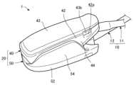
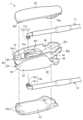
本実施形態に係るパルスオキシメータ1は、被測定者のSpO2(経皮的動脈血酸素飽和度)及び脈波を測定するための測定機器である。図1~図3に示すように、パルスオキシメータ1は、被測定者のSpO2及び脈波を測定可能なプローブ10と、被測定者の指に装着可能な本体部20と、本体部20と被測定者の指との間に設けられ、被測定者の指と接触するパッド部30とを備えている。 [Overall configuration of pulse oximeter]
The
以下本実施形態において、説明の便宜上、被測定者の指に本体部20が装着される方向を「前方」、これとは反対の方向を「後方」として説明する。また、被測定者の指に本体部20を装着した状態において、被測定者の指の爪が位置する方向を「上方」、これとは反対の被測定者の指の腹が位置する方向を「下方」として説明する。但し、ここでいう前後方向及び上下方向は、実際の使用状況における前後方向及び上下方向とは限らない。For ease of explanation, in the following embodiment, the direction in which the
[プローブの構成]
以下、図1~図3を用いてプローブ10の構成について説明する。プローブ10は、被測定者のSpO2及び脈波を測定するための測定機器である。具体的には、プローブ10は、先端部11aが略垂直に折れ曲がって形成された長尺紐状の第1プローブ11と、同じく先端部12aが略垂直に折れ曲がって形成された長尺紐状の第2プローブ12とを備えている。 [Probe configuration]
The configuration of the
この第1プローブ11の先端部11aには、被測定者の指に対して光を照射する発光部11bが設けられており、第2プローブ12の先端部12aには、被測定者の指を透過した光を受光する受光部12bが設けられている。また、第1プローブ11の先端部11aには、先端部11aの外周面から先端部11aの径方向外側に向けて突出する係合凸部11cが設けられており、第2プローブ12の先端部12aには、先端部12aの外周面から先端部12aの径方向外側に向けて突出する係合凸部12cが設けられている。The
また、第1プローブ11及び第2プローブ12の後端部は、不図示のモニタに接続されており、このモニタに、発光部11bから被測定者の指に対して照射された光の光量と、受光部12bが受光した光の光量とに基づいて算出される被測定者のSpO2及び脈波が表示される。なお、プローブ10及び不図示のモニタは、種々の公知の構成を採用可能であるため、その詳細な説明を省略する。 The rear ends of the
[本体部の構成]
本体部20は、被測定者の指に本体部20を装着した状態において(図5参照)、指の爪側を覆う第1本体部40と、指の腹側を覆う第2本体部50とを備えており、全体として前後方向に延びる長尺状に形成されている。なお、第1本体部40が指の腹側を覆い、第2本体部50が指の爪側を覆う構成としても良い。 [Configuration of main body]
The
以下、図1~図3を用いて第1本体部40の構成について説明する。第1本体部40は、前後方向に延びる長尺状のベース部41と、ベース部41の外縁から上方に向けて延びる周壁部42と、ベース部41の上面(表面)を覆う蓋部43と、ベース部41の短手方向両端部から下方に向けて延びる側面部44とを備えている。また、第1本体部40は、ベース部41と、周壁部42と、蓋部43とによって形成された収容空間45に第1プローブ11の一部(先端部11a側)を収容可能に構成されている。The configuration of the
ベース部41は、平面視において略矩形状に形成されており、ベース部41の前端部と中心部との間に円状の開口部41aを備えている。この開口部41aは、ベース部41の上面からベース部41の下面(第1本体部40の内面かつ被測定者の指との対向面)に亘って貫通して形成されている。また、ベース部41は、開口部41aの後端部近傍に形成された一対の突出部41bと、ベース部41の後端部近傍から第1本体部40の後端に亘って形成されたU字状の溝部41cとを備えている。すなわち、本実施形態において、U字状の溝部41cが形成されている部分には、周壁部42が形成されていない。The
一対の突出部41bは、各々がブロック状に形成されており、ベース部41の短手方向に沿って対向するように、ベース部41の上面に立設している。溝部41cは、ベース部41の短手方向一端部近傍に設けられており、第1プローブ11を収容可能な溝幅を有している。The pair of
ベース部41は、これら開口部41aと、一対の突出部41bと、溝部41cとにより、第1プローブ11を着脱可能に構成されている。具体的には、ベース部41は、開口部41aに第1プローブ11の先端部11aを挿入させると共に、一対の突出部41bの間及び溝部41cに第1プローブ11を挿入させることにより、第1プローブ11を取り付け可能に構成されており、これとは反対の動作を行うことにより、第1プローブ11を取り外し可能に構成されている。これにより、プローブ10及び本体部20のいずれか一方が故障又は破損した場合であっても、故障又は破損したプローブ10又は本体部20のみを交換するだけで、再度パルスオキシメータ1が使用可能になるという利点がある。The
また、ベース部41は、開口部41aによって形成された内壁の下端部近傍から内側に突出して形成された係合突起41dを備えている。The
ベース部41の前端部の下面は、被測定者の指の表面に沿うような上方に向けて緩やかに湾曲した形状を有している。このベース部41の前端部の下面には、パッド部30を収容可能なパッド収容凹部46が形成されている。パッド収容凹部46は、パッド部30の後述する逆傾斜部34の先端部と対向する底面46aと、底面46aの外縁(外周縁)から被測定者の指側(下方)に向けて延びる壁部46bとを備えており、全体としてベース部41の下面よりも上方に凹んだ形状を有している。The underside of the front end of the
底面46aは、円状に形成されており、底面46aの中心部に、ベース部41の開口部41aを配している。壁部46bは、底面46aの外縁から、底面46aの径方向外側かつ被測定者の指側(下方)に向けて傾斜して形成されている。なお、底面46aが底面46aの外縁から測定者の指側(下方)に向けて垂直に延びる構成であっても良い(図6参照)。The
蓋部43は、ベース部41の上面を覆うのに十分な大きさで形成されており、ベース部41に対して着脱可能に構成されている。具体的には、蓋部43は、ベース部41の前端部の上面に形成された一対の突起部41eに係合可能な係合部43aと、第1本体部40の後端部において、周壁部42の一部が切り欠かれて形成された一対の切り欠き42aに嵌合可能な突出片部43bとを備えている。The
蓋部43は、係合部43aがベース部41の突起部41eに係合し、突出片部43bが周壁部42の一対の切り欠き42aに嵌合したときに、ベース部41に対して取り付けられるように構成されており、これとは反対の動作をしたときに、ベース部41から取り外されるように構成されている。側面部44は、下方に向けて面積が減少する略逆三角形状に形成されており、後述する第2本体部50の側面部54と併せて外部の光を遮光するように構成されている。The
本実施形態において、ベース部41、周壁部42及び側面部44は、例えば、ABS、PC(ポリカーボネート)等の材料により一体成形に形成することができる。また、蓋部43は、例えば、ABS、PC(ポリカーボネート)等の材料により形成することができる。なお、ベース部41、周壁部42及び側面部44が一体的に形成される構成であっても良い。In this embodiment, the
次に、図1~図3を用いて第2本体部50の構成について説明する。第2本体部50は、第1本体部40のベース部41に対向し、前後方向に延びる長尺状のベース部51と、ベース部51の外縁から下方に向けて延びる周壁部52と、ベース部51の下面を覆う蓋部53と、ベース部51の短手方向両端部から上方に向けて延びる側面部54とを備えている。また、第2本体部50は、ベース部51と、周壁部52と、蓋部53とによって形成された収容空間55に第2プローブ12の一部(先端部12a側)を収容可能に構成されている。Next, the configuration of the
本実施形態において、第2本体部50は、基本的には第1本体部40を180°回転させた形状を有しており、第2本体部50の各構成も第1本体部40の各構成と同様であるため、その詳細な説明を省略するものとし、以下、第1本体部40と相違する構成についてのみ説明をする。In this embodiment, the
第2本体部50のベース部51は、短手方向において、第1本体部40のベース部41よりも若干長尺に形成されている。このため、第2本体部50の側面部54が第1本体部40の側面部44の表面を覆うように形成されている。この側面部54は、ベース部51の中心部近傍から前端部に亘って設けられており、上方に向けて面積が若干減少する略山状に形成されている。側面部54は、第1本体部40の側面部44と併せて外部の光を遮光するように構成されている。The
また、ベース部51の前端部の上面は、第1本体部40のベース部41の前端部の下面の曲率と同程度の曲率を有する下方に向けて湾曲した形状を有している。このベース部51の前端部の上面には、第1本体部40のパッド収容凹部46と相互に対向し、パッド部30を収容可能なパッド収容凹部56が形成されている。また、ベース部51の前端部の上面は、パッド収容凹部56の後方部分に、第1本体部40側かつ後方に向けて傾斜する停止部(ストッパ)57を備えている。第2本体部50に停止部57が設けられていることにより、本体部20は、被測定者の指を装着した状態において、被測定者の指が本体部20の後端部にまで進入することを防止することができる。The upper surface of the front end of the
また、第2本体部50は、蓋部53の前端部に設けられ、ベース部51の前端部の下面に形成された不図示の突起部と係合する係合部53aが、蓋部53の短手方向両端部近傍に一対形成されている点で、第1本体部40と構成が相違している。The second
上述した構成を有する第1本体部40及び第2本体部50は、互いに接近又は離間可能に設けられている。具体的には、第1本体部40及び第2本体部50は、不図示の軸部により開閉可能に連結されており、第1本体部40及び第2本体部50の後端部が相互に離間しているときには、第1本体部40及び第2本体部50の前端部が相互に接近し、第1本体部40及び第2本体部50の後端部が相互に接近しているときには、第1本体部40及び第2本体部50の前端部が相互に離間するように構成されている。なお、軸部は、例えば、第1本体部40又は第2本体部50と一体成形又は一体的に形成される構成や、第1本体部40及び第2本体部50とは独立した部材である構成等、種々の公知の構成を採用可能であるため、その詳細な説明を省略する。The
[パッド部の構成]
以下、図3及び図4を用いてパッド部30の構成について説明する。パッド部30は、図3に示すように、第1本体部40と被測定者の指との間、及び第2本体部50と被測定者の指との間にそれぞれ設けられている。パッド部30は、図4(b)に示すように、側面視(断面視)において傘状に形成されており、図4(a)に示すように、正面視において上下対称かつ左右対称な円形状に形成されている。具体的には、パッド部30は、第1本体部40又は第2本体部50(本体部20)と連結可能な連結部31と、発光部11bから放射された光又は受光部12bにより受光される光が通過する透光部32と、透光部32から径方向外側かつ被測定者の指側に向けて傾斜する傾斜部33と、傾斜部33の先端部から径方向外側かつ第1本体部40又は第2本体部50側(本体部20側)に向けて傾斜する逆傾斜部34とを備えている。 [Pad section configuration]
The configuration of the
本実施形態において、第1本体部40と被測定者の指との間、及び第2本体部50と被測定者の指との間に設けられるパッド部30は、いずれも同一の構成を備えているため、以下、第1本体部40と被測定者の指との間に設けられるパッド部30を用いて、パッド部30の構成を説明するものとする。In this embodiment, the
連結部31は、上下方向に沿って延びる略円筒状に形成されており、第1本体部40の開口部41aに収容可能な大きさを有している。この連結部31の外周面には、連結部31の上下方向の中心部が切り欠かれて形成された係合溝部31aが連結部31の周方向に沿って設けられている。パッド部30は、連結部31の係合溝部31aが第1本体部40の係合突起41dと係合することにより、第1本体部40に対して取り付けられるように構成されている。The connecting
また、連結部31の内周面には、連結部31の上下方向の中心部が凹んで形成された係合凹部31bが周方向に沿って設けられている。この連結部31の係合凹部31bは、第1プローブ11の先端部11aが第1本体部40の開口部41aに挿入された状態において、第1プローブ11の係合凸部11cと係合するように構成されている。The inner peripheral surface of the connecting
透光部32は、連結部31の内周面によって画定された、連結部31の軸方向に沿って貫通する開口である。本実施形態において、透光部32は、透光部32としての開口に第1プローブ11の先端部11aを挿入させることにより、すなわち、透光部32としての開口に発光部11bを位置させることにより、発光部11bから放射された光を通過させるように構成されている。この点は、受光部12bにより受光される光を通過させる場合においても同様である。The light-transmitting
上述のとおり、本実施形態において、透光部32は、連結部31の軸方向に沿って貫通する開口であるものとして説明したが、これに限定されず、例えば、光を透過させることが可能な種々の公知の材料により形成したシート状又は平板状の部材を透光部32として採用し、このシート状又は平板状の部材により、連結部31の開口の被測定者の指側を覆う構成としても良い(図6参照)。また、光を透過させることが可能な種々の公知の材料により、連結部31の開口を充填し、この充填された部位を透光部32として採用する構成としても良い。As described above, in this embodiment, the light-transmitting
また、本実施形態において、透光部32は、透光部32としての開口に発光部11bを位置させることにより、発光部11bから放射された光を通過させるように構成されているものとして説明したが、これに限定されず、第1プローブ11の先端部11aを第1本体部40の開口部41aに挿入させず、第1本体部40の収容空間45に位置させた状態において、透光部32が発光部11bから放射された光を通過させる構成としても良い。In addition, in this embodiment, the light-transmitting
傾斜部33は、透光部32から径方向外側かつ被測定者の指側に向けて傾斜して形成されており、平面視において環状に形成されている(図4(a)参照)。なお、本明細書において、「透光部から径方向外側かつ被測定者の指側に向けて傾斜」には、透光部の径方向端部から被測定者の指側に向けて傾斜する構成と、透光部の径方向端部近傍、すなわち透光部の径方向端部より離れた位置から被測定者の指側に向けて傾斜する構成との双方の構成が含まれる。The
このような平面視において環状に形成されている傾斜部33は、図4(b)に示すように、その外径の長さL1が、被測定者の指とパッド部30との密着性を良好にして光漏れを防止する観点から、7mm以上11mm以下であることが好ましく、被測定者の指とパッド部30との密着性を良好にしつつ、様々な指の大きさに対応させることを可能にする観点から、8mm以上10mm以下で形成されていることが好ましい。特に、大人を対象とするパルスオキシメータ1の場合には、9~11mmであることが好ましく、乳幼児又は子供を対象とするパルスオキシメータ1の場合には、7~9mmであることが好ましい。As shown in FIG. 4(b), the
本実施形態において、傾斜部33は、透光部32の径方向端部近傍から被測定者の指側に向けて延びて形成されている。具体的には、傾斜部33は、連結部31の表面(被測定者の指側の面)かつ、連結部31の外周縁部から被測定者の指側に向けて延びて形成されている。また、傾斜部33は、傾斜部33の基端部(本体部20、すなわち第1本体部40側の端部)から、傾斜部33の先端部(被測定者の指側の端部)に架けて湾曲する曲面状に形成されている。In this embodiment, the
逆傾斜部34は、傾斜部33の先端部から径方向外側かつ第1本体部40側(本体部20側)に向けて傾斜して形成されている。この逆傾斜部34は、逆傾斜部34の基端部(傾斜部33の先端部)から、逆傾斜部34の先端部(本体部20、すなわち第1本体部40側の端部)に架けて湾曲する曲面状に形成されている。具体的には、逆傾斜部34は、傾斜部33と同じ曲率を有している。これにより、被測定者の指がパッド部30に接触したときに、パッド部30が均一に潰れて変形するため、被測定者の指がパッド部30からずれて光漏れが生じる事態を防止すると共に、被測定者の指と発光部11b及び受光部12bとの密着性を良好にするという利点がある。The
本実施形態において、逆傾斜部34の先端部と第1本体部40(本体部20)との間には、空間が形成されている。これにより、被測定者の指がパッド部30に接触したときに、逆傾斜部34の先端部と第1本体部40との間に形成された空間の分だけパッド部30が潰れて変形するため、被測定者の指と発光部11b及び受光部12bとの密着性が良好になるという利点がある。In this embodiment, a space is formed between the tip of the
具体的には、図3に示すように、逆傾斜部34の先端部と、第1本体部40の底面46aとの間の距離L2が、連結部31の表面から傾斜部33の先端部までの高さL3(図4(b)参照)±0.2~0.3mmであることが好ましい。しかしながら、この高さL3は、薄肉で硬度の柔らかい材料の場合には大きく設定され、厚肉で硬度が固い材料の場合には小さく設定される等、パッド部30の材質や、傾斜部33及び逆傾斜部34の肉厚に応じて設定されるものである。以上の観点から、距離L2は、高さL3と、パッド部30の材質と、傾斜部33及び逆傾斜部34の肉厚とに応じて、パッド部30の変形量を十分に確保することができる範囲に設定されることが好ましい。Specifically, as shown in FIG. 3, it is preferable that the distance L2 between the tip of the reverse inclined
例えば、硬度50°以上の材質の場合、撓み難くなるので、距離L2は高さL3と同等又はそれ以上の空間が必用となり、反対に、硬度が30°以下の材質の場合、距離L2はL3と同等又はそれ以下の空間にして圧接させる必要がある。距離L2の一例として、硬度30°かつ肉厚が0.5mmのエラストマーを使用した場合、高さL3は、1±0.2mm程度に設定されることが好ましいため、距離L2は、0.8~1.0mmに設定される。For example, in the case of a material with a hardness of 50° or more, it is difficult to bend, so distance L2 needs to be equal to or greater than height L3. Conversely, in the case of a material with a hardness of 30° or less, distance L2 needs to be equal to or less than L3 for pressure contact. As an example of distance L2, when an elastomer with a hardness of 30° and a thickness of 0.5 mm is used, height L3 is preferably set to about 1±0.2 mm, so distance L2 is set to 0.8 to 1.0 mm.
また、本実施形態において、逆傾斜部34の先端部と第1本体部40の壁部46bとの間には、空間が形成されている。これにより、被測定者の指がパッド部30に接触したときに、逆傾斜部34の先端部と第1本体部40の壁部46bとの間に形成された空間の分だけパッド部30が潰れて変形するため、被測定者の指と発光部11b及び受光部12bとの密着性が良好になるという利点がある。In addition, in this embodiment, a space is formed between the tip of the
具体的には、図3に示すように、逆傾斜部34の先端部と、壁部46bにおける逆傾斜部34との距離が最も近い部位との間の距離、すなわち、逆傾斜部34の先端部と、第1本体部40の底面46aの外周縁との間の距離L4が、0.2~0.3mm+(高さL3-傾斜部33及び逆傾斜部34の肉厚)で設定されることが好ましい。例えば、高さL3が1.1mmかつ傾斜部33及び逆傾斜部34の肉厚が0.5mmの場合、距離L4は、0.8~0.9mmに設定される。Specifically, as shown in FIG. 3, it is preferable that the distance between the tip of the reverse inclined
また、本実施形態において、パッド部30の傾斜部33及び逆傾斜部34と、第1本体部40(本体部20)との間には、空間が形成されている。すなわち、本実施形態において、傾斜部33及び逆傾斜部34は、曲面状に形成されているため、傾斜部33及び逆傾斜部34と、第1本体部40(本体部20)との間に空間が形成される。In addition, in this embodiment, a space is formed between the
本実施形態において、連結部31と、透光部32と、傾斜部33と、逆傾斜部34とは、エラストマーにより一体成形に形成されている。これにより、パッド部30が弾性変形すると共に、被測定者の指に対する滑り止めとして機能するという利点を有する。なお、本実施形態において、連結部31と、透光部32と、傾斜部33と、逆傾斜部34とは、エラストマーにより一体成形に形成されているものとして説明したが、これに限定されず、パッド部30が他の種々の公知の材料により形成されても良いし、連結部31と、透光部32と、傾斜部33と、逆傾斜部34とが一体的に形成される構成であっても良い。In this embodiment, the connecting
[パルスオキシメータの使用方法]
以下、図1、図2及び図5を用いて本実施形態に係るパルスオキシメータ1の使用方法について説明する。まず、図1及び図2に示すように、後端部が不図示のモニタに接続された第1プローブ11を第1本体部40に取り付けると共に、同じく後端部が不図示のモニタに接続された第2プローブ12を第2本体部50に取り付ける。 [How to use a pulse oximeter]
A method of using the
そして、図5に示すように、第1本体部40に第1プローブ11を収容させ、第2本体部50に第2プローブ12を収容させた状態において、第1本体部40と第2本体部50とで、被測定者の指を挟み込み、被測定者のSpO2及び脈波を測定する。このとき、被測定者の指がパッド部30に密着すると共に、パッド部30が変形して被測定者の指が第1プローブ11の発光部11b及び第2プローブ12の受光部12bに密着するため、発光部11bから放射される光及び受光部12bが受光する光が漏れない。 5, with the
なお、本実施形態において、パルスオキシメータ1は、被測定者の指に装着して使用するものとして説明したが、これに限定されず、例えば、耳朶等の、被測定者のSpO2及び脈波を測定することが可能な被測定者の他の部位にパルスオキシメータ1を装着して測定を行っても良い。 In this embodiment, the
[本実施形態に係るパルスオキシメータの利点]
このように、本実施形態に係るパルスオキシメータ1は、被測定者の指に装着可能な本体部20と、本体部20と被測定者の指との間に設けられ、被測定者の指と接触するパッド部30とを備え、本体部20は、被測定者の指に対して光を照射する発光部11bと、被測定者の指を透過した光を受光する受光部12bとを収容可能に構成されており、パッド部30は、発光部11bから放射された光又は受光部12bにより受光される光が通過する透光部32と、透光部32から径方向外側かつ被測定者の指側に向けて傾斜する傾斜部33とを有している。 [Advantages of the pulse oximeter according to this embodiment]
Thus, the
このような構成を備えるパルスオキシメータ1によれば、本体部20と被測定者の指との間にパッド部30が設けられているため、被測定者の指がパッド部30、発光部11b及び受光部12bと密着するため、被測定者の指と発光部11b及び受光部12bとの間から光漏れが発生しないという利点がある。そのため、測定時間や測定誤差を低減することができる。With the
また、本実施形態に係るパルスオキシメータ1において、パッド部30は、傾斜部33の先端部から径方向外側かつ本体部20側に向けて傾斜する逆傾斜部34を有し、逆傾斜部34の先端部と本体部20との間に空間が形成されている。このような構成を備えるパルスオキシメータ1によれば、被測定者の指がパッド部30に接触したときに、逆傾斜部34の先端部と本体部20との間に形成された空間の分だけパッド部30が潰れて変形するため、被測定者の指と発光部11b及び受光部12bとの密着性が良好になるという利点がある。In the
さらに、本実施形態に係るパルスオキシメータ1において、本体部20は、パッド部30を収容可能なパッド収容凹部46(56)を有し、パッド収容凹部46(56)は、パッド部30の逆傾斜部34の先端部と対向する底面46aと、底面46aの外縁から被測定者の指側に向けて延びる壁部46bとを有し、逆傾斜部34の先端部と壁部46bとの間に空間が形成されている。このような構成を備えるパルスオキシメータ1によれば、被測定者の指がパッド部30に接触したときに、逆傾斜部34の先端部と本体部20の壁部46bとの間に形成された空間の分だけパッド部30が潰れて変形するため、被測定者の指と発光部11b及び受光部12bとの密着性が良好になるという利点がある。Furthermore, in the
また、本実施形態に係るパルスオキシメータ1において、パッド部30の傾斜部33及び逆傾斜部34と、本体部20との間に空間が形成されている。このような構成を備えるパルスオキシメータ1によれば、被測定者の指がパッド部30に接触したときに、パッド部30が潰れて変形しやすくなるため、被測定者の指と発光部11b及び受光部12bとの密着性が良好になるという利点がある。In addition, in the
さらに、本実施形態に係るパルスオキシメータ1において、本体部20は、互いに接近又は離間可能に設けられた第1本体部40及び第2本体部50を有し、パッド部30は、第1本体部40と被測定者の指との間、及び第2本体部50と被測定者の指との間に設けられている。このような構成を備えるパルスオキシメータ1によれば、パッド部30が第1本体部40と被測定者の指との間と、及び第2本体部50と被測定者の指との間との双方に設けられているため、被測定者の指と発光部11b及び受光部12bとの間から生じる光漏れを確実に防止し、測定時間や測定誤差を低減するという利点を有する。Furthermore, in the
[変形例]
本発明に係るパルスオキシメータは、上述した実施形態に限定されるものではなく、本発明の技術思想を逸脱しない範囲内において種々の改変を行なうことができる。 [Modification]
The pulse oximeter according to the present invention is not limited to the above-described embodiment, and various modifications can be made without departing from the technical spirit of the present invention.
例えば、上述した実施形態では、パッド部30が傾斜部33の先端部から径方向外側かつ本体部20側に向けて傾斜する逆傾斜部34を有し、側面視(断面視)におけるパッド部30の形状が傘状であるものとして説明したが、これに限定されるものではない。例えば、パッド部30が逆傾斜部34を備えない構成としても良い。また、上述した実施形態では、逆傾斜部34の先端部と本体部20との間に空間が形成されているものとして説明したが、これに限定されず、逆傾斜部34の先端部と本体部20との間に空間が形成されない構成としても良い。For example, in the above-described embodiment, the
また、上述した実施形態では、本体部20がパッド部30を収容可能なパッド収容凹部46(56)を有し、パッド収容凹部46(56)は、パッド部30の逆傾斜部34の先端部と対向する底面46aと、底面46aの外縁から被測定者の指側に向けて延びる壁部46bとを有し、逆傾斜部34の先端部と壁部46bとの間に空間が形成されているものとして説明したが、これに限定されず、例えば、本体部20がパッド収容凹部46(56)を備えない構成としても良いし、逆傾斜部34の先端部と壁部46bとの間に空間が形成されない構成としても良い。In the above-described embodiment, the
さらに、上述した実施形態では、パッド部30の傾斜部33及び逆傾斜部34と、本体部20との間に空間が形成されているものとして説明したが、これに限定されず、例えば、パッド部30の傾斜部33及び逆傾斜部34と、本体部20との間が、弾性変形可能な種々の公知の材料により充填される構成としても良い。Furthermore, in the above-mentioned embodiment, a space is formed between the
また、上述した実施形態では、本体部20は、互いに接近又は離間可能に設けられた第1本体部40及び第2本体部50を有し、パッド部30が、第1本体部40と被測定者の指との間、及び第2本体部50と被測定者の指との間に設けられているものとして説明したが、これに限定されず、例えば、本体部20が第1本体部40及び第2本体部50のいずれか一方を備える構成としても良いし、パッド部30が、第1本体部40と被測定者の指との間、及び第2本体部50と被測定者の指との間のいずれか一方に設けられる構成としても良い。In the above-described embodiment, the
さらに、上述した実施形態では、プローブ10が発光部11bを有する第1プローブ11と、受光部12bを有する第2プローブ12とを備えているものとして説明したが、これに限定されず、例えば、1つのプローブに発光部11b及び受光部12bが設けられる構成としても良い。Furthermore, in the above-mentioned embodiment, the
また、上述した実施形態では、発光部11bと相互に対向して設けられた受光部12bが、被測定者の指を透過した光を受光するように構成されており、パッド部30の透光部32が発光部11bから放射された光又は受光部12bにより受光される光を通過させるものとして説明したが、これに限定されず、例えば、発光部11bと受光部12bとが並べて配置されており、受光部12bが被測定者の指に反射した光を受光するように構成され、パッド部30の透光部32が発光部11bから放射された光及び受光部12bにより受光される光を通過させる、所謂反射型のパルスオキシメータとしても良い。In the above-described embodiment, the light-emitting
さらに、上述した実施形態では、パルスオキシメータ1は、発光部11bを有する第1プローブ11を第1本体部40に装着し、受光部12bを有する第2プローブ12を第2本体部50に装着するものとして説明したが、これに限定されず、例えば、発光部11bを有する第1プローブ11を第2本体部50に装着し、受光部12bを有する第2プローブ12を第1本体部40に装着する構成としても良い。Furthermore, in the above-mentioned embodiment, the
また、上述した実施形態では、ベース部41が開口部41aと、一対の突出部41bと、溝部41cとにより、第1プローブ11を着脱可能に構成されているものとして説明したが、これに限定されず、例えば、ベース部41が第1プローブ11を着脱不能な構成としても良い。In addition, in the above-described embodiment, the
さらに、上述した実施形態では、蓋部43がベース部41に対して着脱可能に構成されているものとして説明したが、これに限定されず、例えば、蓋部43がベース部41に対して着脱不能な構成としても良い。Furthermore, in the above-described embodiment, the
また、上述した実施形態では、パッド部30は、第1本体部40と被測定者の指との間に設けられるパッド部30と、第2本体部50と被測定者の指との間に設けられるパッド部30とが同一の構成を備えるものとして説明したが、これに限定されず、例えば、第1本体部40と被測定者の指との間に設けられるパッド部30と、第2本体部50と被測定者の指との間に設けられるパッド部30とが、異なる大きさを有している等、異なる構成を有していても良い。In the above-described embodiment, the
さらに、パルスオキシメータ1は、発光部11bを有する第1プローブ11を第1本体部40に装着し、受光部12bを有する第2プローブ12を第2本体部50に装着するものとして説明したが、これに限定されず、例えば、図6に示すパルスオキシメータ1´のように、本体部20´の内部に発光部11b´及び受光部12b´として機能する種々の公知の素子を設ける構成としても良い。また、図6に示すように、パッド部30´の連結部31´が第1本体部40´(第2本体部50´)の底面46a´に形成された溝に嵌合する構成としても良い。Furthermore, the
また、上述した実施形態では、パッド部30が、正面視において上下対称かつ左右対称な円形状に形成されるものとして説明したが、これに限定されるものではない。例えば、上下非対称な形状としても良いし、左右非対称な形状としても良い。また、全方位からの光漏れ防止という観点では円形が最適であるが、これに限定されず、楕円形状や瓦形状など、種々の形状を採用することが可能である。In the above embodiment, the
上記のような変形例が本発明の範囲に含まれることは、特許請求の範囲の記載から明らかである。It is clear from the claims that the above-mentioned modifications are included within the scope of the present invention.
1、1´ :パルスオキシメータ
10 :プローブ
11 :第1プローブ
11a :先端部
11b、11b´ :発光部
11c :係合凸部
12 :第2プローブ
12a :先端部
12b、12b´ :受光部
12c :係合凸部
20、20´ :本体部
30、30´ :パッド部
31、31´ :連結部
31a :係合溝部
31b :係合凹部
32 :透光部
33 :傾斜部
34 :逆傾斜部
40、40´ :第1本体部
41 :ベース部
41a :開口部
41b :突出部
41c :溝部
41d :係合突起
41e :突起部
42 :周壁部
42a :切り欠き
43 :蓋部
43a :係合部
43b :突出片部
44 :側面部
45 :収容空間
46 :パッド収容凹部
46a、46a´ :底面
46b :壁部
50、50´ :第2本体部
51 :ベース部
52 :周壁部
53 :蓋部
53a :係合部
54 :側面部
55 :収容空間
56 :パッド収容凹部
57 :停止部
1, 1': Pulse oximeter 10: Probe 11:
Claims (5)
Translated fromJapanese前記本体部と被測定者の指との間に設けられ、被測定者の指と接触するパッド部と
を備え、
前記本体部は、被測定者の指に対して光を照射する発光部と、被測定者の指を透過した光又は被測定者の指に反射した光を受光する受光部とを収容可能に構成されており、
前記パッド部は、前記発光部から放射された光及び/又は前記受光部により受光される光が通過する透光部と、前記透光部から径方向外側かつ被測定者の指側に向けて傾斜する傾斜部とを有する
ことを特徴とするパルスオキシメータ。 A main body that can be attached to the finger of a person to be measured;
a pad portion provided between the main body portion and the subject's finger and adapted to come into contact with the subject's finger,
The main body is configured to accommodate a light emitting unit that irradiates light onto the subject's finger and a light receiving unit that receives light that has passed through the subject's finger or light that has been reflected by the subject's finger,
a pad portion having a light-transmitting portion through which light emitted from the light-emitting portion and/or light received by the light-receiving portion passes, and an inclined portion inclined radially outward from the light-transmitting portion and toward the finger of the person being measured.
前記逆傾斜部の先端部と前記本体部との間に空間が形成されている
ことを特徴とする請求項1に記載のパルスオキシメータ。 The pad portion has a reverse inclined portion inclined from a tip end of the inclined portion toward a radially outer side and toward the main body portion,
The pulse oximeter according to claim 1 , wherein a space is formed between the tip of the inverted inclined portion and the main body.
前記パッド収容凹部は、前記パッド部の前記逆傾斜部の前記先端部と対向する底面と、前記底面の外縁から被測定者の指側に向けて延びる壁部とを有し、
前記逆傾斜部の前記先端部と前記壁部との間に空間が形成されている
ことを特徴とする請求項2に記載のパルスオキシメータ。 The main body portion has a pad accommodating recess capable of accommodating the pad portion,
the pad accommodating recess has a bottom surface facing the tip end of the reverse inclined portion of the pad portion, and a wall portion extending from an outer edge of the bottom surface toward the subject's finger,
The pulse oximeter according to claim 2 , wherein a space is formed between the tip of the inverted slope portion and the wall portion.
ことを特徴とする請求項2又は3に記載のパルスオキシメータ。 4. The pulse oximeter according to claim 2, wherein a space is formed between the inclined portion and the reverse inclined portion of the pad portion and the main body portion.
前記パッド部は、前記第1本体部と被測定者の指との間、及び前記第2本体部と被測定者の指との間に設けられている
ことを特徴とする請求項1~3のいずれか1項に記載のパルスオキシメータ。
The main body portion includes a first main body portion and a second main body portion that are provided so as to be movable toward or away from each other,
The pulse oximeter according to any one of claims 1 to 3, characterized in that the pad portion is provided between the first main body portion and a finger of the person being measured, and between the second main body portion and a finger of the person being measured.
Priority Applications (2)
| Application Number | Priority Date | Filing Date | Title |
|---|---|---|---|
| JP2023060184AJP2024147269A (en) | 2023-04-03 | 2023-04-03 | Pulse oximeter |
| PCT/JP2024/012292WO2024210018A1 (en) | 2023-04-03 | 2024-03-27 | Pulse oximeter |
Applications Claiming Priority (1)
| Application Number | Priority Date | Filing Date | Title |
|---|---|---|---|
| JP2023060184AJP2024147269A (en) | 2023-04-03 | 2023-04-03 | Pulse oximeter |
Publications (1)
| Publication Number | Publication Date |
|---|---|
| JP2024147269Atrue JP2024147269A (en) | 2024-10-16 |
Family
ID=92971695
Family Applications (1)
| Application Number | Title | Priority Date | Filing Date |
|---|---|---|---|
| JP2023060184APendingJP2024147269A (en) | 2023-04-03 | 2023-04-03 | Pulse oximeter |
Country Status (2)
| Country | Link |
|---|---|
| JP (1) | JP2024147269A (en) |
| WO (1) | WO2024210018A1 (en) |
Family Cites Families (6)
| Publication number | Priority date | Publication date | Assignee | Title |
|---|---|---|---|---|
| US5339810A (en)* | 1993-05-03 | 1994-08-23 | Marquette Electronics, Inc. | Pulse oximetry sensor |
| JP3142046U (en)* | 2008-02-29 | 2008-06-05 | 操 舘野 | Pulse oximeter |
| US20100004518A1 (en)* | 2008-07-03 | 2010-01-07 | Masimo Laboratories, Inc. | Heat sink for noninvasive medical sensor |
| CN210204743U (en)* | 2019-05-13 | 2020-03-31 | 深圳市蓝瑞格生物医疗科技有限公司 | Finger clip type blood oxygen measuring device adaptive to thick and thin fingers |
| CN213940738U (en)* | 2020-11-13 | 2021-08-13 | 江苏迈邦生物科技有限公司 | Disposable pulse oxyhemoglobin saturation probe |
| CN213696918U (en)* | 2020-11-18 | 2021-07-16 | 深圳市鑫康电子科技有限公司 | A wireless oximeter |
- 2023
- 2023-04-03JPJP2023060184Apatent/JP2024147269A/enactivePending
- 2024
- 2024-03-27WOPCT/JP2024/012292patent/WO2024210018A1/enactivePending
Also Published As
| Publication number | Publication date |
|---|---|
| WO2024210018A1 (en) | 2024-10-10 |
Similar Documents
| Publication | Publication Date | Title |
|---|---|---|
| US5080098A (en) | Non-invasive sensor | |
| US8805464B2 (en) | Bio-information measuring apparatus | |
| EP1584287A1 (en) | Clip-type sensor having integrated biasing and cushioning means | |
| US20160120421A1 (en) | Optical detection unit and biological information detection device | |
| US20110118574A1 (en) | Physiological signal sensing device | |
| CN104055508A (en) | Biological Information Detection Apparatus | |
| JP2017153616A (en) | Pulse oximeter probe | |
| CN104055504A (en) | Biological Information Detection Apparatus | |
| JP2007289463A (en) | Biological information measuring apparatus | |
| US8543181B2 (en) | Sensor holder for medical sensor | |
| JP6921760B2 (en) | Biometric information detector | |
| JP2024147269A (en) | Pulse oximeter | |
| JP4170262B2 (en) | Biological information measuring device and standard element | |
| JPWO2008114398A1 (en) | Biological information measuring device | |
| US20160151008A1 (en) | Biological information measuring device | |
| US20180000366A1 (en) | Biological information detection apparatus | |
| US20210085193A1 (en) | Biological information detection device | |
| JP2007029702A (en) | Fingertip clip for photoelectric living body information measuring apparatus | |
| JP6667322B2 (en) | Pulse oximeter probe | |
| US9943238B2 (en) | Pulse wave measuring device | |
| JP2019166267A (en) | Biological information measurement device | |
| CN109414195A (en) | For measuring the device and method of the physiological parameter of human limb | |
| CN109414196B (en) | Device and method for measuring physiological parameters of a human limb | |
| JP6952045B2 (en) | Component measuring device set and component measuring chip | |
| US20210330222A1 (en) | Pulse oximeter |