JP2024142914A - aircraft - Google Patents
aircraftDownload PDFInfo
- Publication number
- JP2024142914A JP2024142914AJP2023055319AJP2023055319AJP2024142914AJP 2024142914 AJP2024142914 AJP 2024142914AJP 2023055319 AJP2023055319 AJP 2023055319AJP 2023055319 AJP2023055319 AJP 2023055319AJP 2024142914 AJP2024142914 AJP 2024142914A
- Authority
- JP
- Japan
- Prior art keywords
- aircraft
- exhaust port
- air
- cruise
- exhaust
- Prior art date
- Legal status (The legal status is an assumption and is not a legal conclusion. Google has not performed a legal analysis and makes no representation as to the accuracy of the status listed.)
- Pending
Links
Images


Classifications
- B—PERFORMING OPERATIONS; TRANSPORTING
- B64—AIRCRAFT; AVIATION; COSMONAUTICS
- B64D—EQUIPMENT FOR FITTING IN OR TO AIRCRAFT; FLIGHT SUITS; PARACHUTES; ARRANGEMENT OR MOUNTING OF POWER PLANTS OR PROPULSION TRANSMISSIONS IN AIRCRAFT
- B64D33/00—Arrangement in aircraft of power plant parts or auxiliaries not otherwise provided for
- B64D33/08—Arrangement in aircraft of power plant parts or auxiliaries not otherwise provided for of power plant cooling systems
- B64D33/10—Radiator arrangement
- B—PERFORMING OPERATIONS; TRANSPORTING
- B64—AIRCRAFT; AVIATION; COSMONAUTICS
- B64D—EQUIPMENT FOR FITTING IN OR TO AIRCRAFT; FLIGHT SUITS; PARACHUTES; ARRANGEMENT OR MOUNTING OF POWER PLANTS OR PROPULSION TRANSMISSIONS IN AIRCRAFT
- B64D33/00—Arrangement in aircraft of power plant parts or auxiliaries not otherwise provided for
- B64D33/04—Arrangement in aircraft of power plant parts or auxiliaries not otherwise provided for of exhaust outlets or jet pipes
- B—PERFORMING OPERATIONS; TRANSPORTING
- B64—AIRCRAFT; AVIATION; COSMONAUTICS
- B64C—AEROPLANES; HELICOPTERS
- B64C27/00—Rotorcraft; Rotors peculiar thereto
- B64C27/82—Rotorcraft; Rotors peculiar thereto characterised by the provision of an auxiliary rotor or fluid-jet device for counter-balancing lifting rotor torque or changing direction of rotorcraft
- B—PERFORMING OPERATIONS; TRANSPORTING
- B64—AIRCRAFT; AVIATION; COSMONAUTICS
- B64D—EQUIPMENT FOR FITTING IN OR TO AIRCRAFT; FLIGHT SUITS; PARACHUTES; ARRANGEMENT OR MOUNTING OF POWER PLANTS OR PROPULSION TRANSMISSIONS IN AIRCRAFT
- B64D27/00—Arrangement or mounting of power plants in aircraft; Aircraft characterised by the type or position of power plants
- B64D27/02—Aircraft characterised by the type or position of power plants
- B64D27/30—Aircraft characterised by electric power plants
- B64D27/34—All-electric aircraft
- B—PERFORMING OPERATIONS; TRANSPORTING
- B64—AIRCRAFT; AVIATION; COSMONAUTICS
- B64D—EQUIPMENT FOR FITTING IN OR TO AIRCRAFT; FLIGHT SUITS; PARACHUTES; ARRANGEMENT OR MOUNTING OF POWER PLANTS OR PROPULSION TRANSMISSIONS IN AIRCRAFT
- B64D33/00—Arrangement in aircraft of power plant parts or auxiliaries not otherwise provided for
- B64D33/08—Arrangement in aircraft of power plant parts or auxiliaries not otherwise provided for of power plant cooling systems
- B—PERFORMING OPERATIONS; TRANSPORTING
- B64—AIRCRAFT; AVIATION; COSMONAUTICS
- B64C—AEROPLANES; HELICOPTERS
- B64C27/00—Rotorcraft; Rotors peculiar thereto
- B64C27/82—Rotorcraft; Rotors peculiar thereto characterised by the provision of an auxiliary rotor or fluid-jet device for counter-balancing lifting rotor torque or changing direction of rotorcraft
- B64C2027/8227—Rotorcraft; Rotors peculiar thereto characterised by the provision of an auxiliary rotor or fluid-jet device for counter-balancing lifting rotor torque or changing direction of rotorcraft comprising more than one rotor
- B—PERFORMING OPERATIONS; TRANSPORTING
- B64—AIRCRAFT; AVIATION; COSMONAUTICS
- B64C—AEROPLANES; HELICOPTERS
- B64C27/00—Rotorcraft; Rotors peculiar thereto
- B64C27/82—Rotorcraft; Rotors peculiar thereto characterised by the provision of an auxiliary rotor or fluid-jet device for counter-balancing lifting rotor torque or changing direction of rotorcraft
- B64C2027/8254—Shrouded tail rotors, e.g. "Fenestron" fans
Landscapes
- Engineering & Computer Science (AREA)
- Mechanical Engineering (AREA)
- Aviation & Aerospace Engineering (AREA)
- Chemical & Material Sciences (AREA)
- Combustion & Propulsion (AREA)
- Cooling, Air Intake And Gas Exhaust, And Fuel Tank Arrangements In Propulsion Units (AREA)
- Arrangement Or Mounting Of Propulsion Units For Vehicles (AREA)
Abstract
Description
Translated fromJapanese本発明は、航空機に関する。The present invention relates to aircraft.
近年、低炭素社会又は脱炭素社会の実現に向けた取り組みが活発化し、航空機においてもCO2排出量の削減やエネルギー効率の改善のための研究開発が行われている。 In recent years, efforts to realize a low-carbon or carbon-free society have become more active, and research and development is being conducted to reduceCO2 emissions and improve energy efficiency in aircraft.
例えば、特許文献1には、エンジンの排気を排出する排気口の後方にクルーズロータ(プロペラ)を配置した航空機が開示されている。For example, Patent Document 1 discloses an aircraft in which a cruise rotor (propeller) is positioned behind the exhaust port through which the engine exhaust is discharged.
より良好な航空機が待望されている。Better aircraft are eagerly awaited.
本発明は、上述した課題を解決することを目的とする。The present invention aims to solve the above-mentioned problems.
本発明の一態様は、機体と、前記機体に設けられたエンジンと、前記機体の後端部に設けられて前記エンジンの排気ガスを外部に排出するための排気口と、前記排気口よりも前記機体の後方に位置して前記機体に水平方向の推力を発生させるためのクルーズロータと、を備え、前記排気口と前記クルーズロータとは、前記排気ガスの排出方向から見て互いに重ならない、航空機である。One aspect of the present invention is an aircraft comprising an airframe, an engine mounted on the airframe, an exhaust port mounted at the rear end of the airframe for discharging exhaust gas from the engine to the outside, and a cruise rotor positioned rearward of the exhaust port on the airframe for generating horizontal thrust on the airframe, wherein the exhaust port and the cruise rotor do not overlap each other when viewed from the exhaust gas discharge direction.
本発明の他の態様は、機体と、前記機体に設けられたエンジンと、前記機体の後端部に設けられて前記エンジンの排気ガスを外部に排出するための排気口と、前記排気口よりも前記機体の後方に位置して前記機体に水平方向の推力を発生させるためのクルーズロータと、を備え、前記排気口と前記クルーズロータとは、前記機体の背面視で互いに重ならないように配置されている、航空機である。Another aspect of the present invention is an aircraft comprising an airframe, an engine mounted on the airframe, an exhaust port provided at the rear end of the airframe for discharging exhaust gas from the engine to the outside, and a cruise rotor located rearward of the exhaust port on the airframe for generating horizontal thrust on the airframe, the exhaust port and the cruise rotor being positioned so as not to overlap each other when viewed from the rear of the airframe.
本発明によれば、良好な航空機を提供することができる。The present invention makes it possible to provide a good aircraft.
排気口とクルーズロータとを単に配した場合には、排気口から排出される排気ガスの熱によってクルーズロータが過度に熱せられてしまう虞がある。本願発明者らは鋭意検討した結果、以下のような航空機を想到した。If the exhaust port and cruise rotor were simply arranged, there is a risk that the heat of the exhaust gases coming out of the exhaust port would cause the cruise rotor to become overheated. After extensive research, the inventors of the present application came up with the following aircraft.
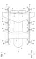
本発明の一実施形態に係る航空機10について図面を用いて以下に説明する。図1に示すように、本実施形態に係る航空機10は、例えば、電動垂直離着陸機(eVTOL:Electric Vertical Take-Off and Landing aircraft)である。An
航空機10は、機体12と、前翼部14と、後翼部16と、8つのVTOLロータ18と、8つのVTOLモータ20と、2つのクルーズロータ22と、4つのクルーズモータ24とを有する。機体12は、航空機10の前後方向に延在している。機体12の後端部は、後方に向かって縮径している(図1及び図2参照)。The
前翼部14は、機体12の前後方向の中央よりも前方の部分に設けられている。後翼部16は、機体12の後端部に設けられている。後翼部16は、機体12の上端部に取り付けられている。後翼部16は、機体12の左右方向に延在している。The
VTOLロータ18は、航空機10に対して上方向の推力を発生させる。1つのVTOLロータ18には、1つのVTOLモータ20が接続されている。VTOLモータ20は、VTOLロータ18を回転させるための電動モータである。クルーズロータ22は、航空機10に対して水平方向の推力を発生させる。1つのクルーズロータ22には、2つのクルーズモータ24が接続されている。クルーズモータ24は、クルーズロータ22を回転させるための電動モータである。The
VTOLロータ18、VTOLモータ20、クルーズロータ22及びクルーズモータ24の各々の数及び配置は、適宜設定可能である。1つのクルーズロータ22には、クルーズモータ24が1つのみ接続されてもよい。換言すれば、クルーズモータ24は、左右のクルーズロータ22に1つずつの合計2つであってもよい。The number and arrangement of the
図2に示すように、機体12の内部には、一対の発電モジュール28と、一対の電子機器30とが配置されている。一対の発電モジュール28は、機体12の左右方向の中心線A1に対して左右対称に配置されている。中心線A1は、機体12の前後方向に延在している。一対の発電モジュール28は、中心線A1に対して左右対称に配置されていなくてもよい。As shown in FIG. 2, a pair of
発電モジュール28は、エンジン32と、回転電機34と、排気装置36とを含む。エンジン32は、例えば、ガスタービンエンジンである。エンジン32は、燃料を燃焼させることにより高温の燃焼ガスを発生させ、当該燃焼ガスにより図示しないタービンを駆動させる。なお、エンジン32は、ガスタービンエンジンに限定されず、適宜の内燃機関又は外燃機関であってもよい。The
回転電機34は、エンジン32に接続されている。回転電機34は、例えば、エンジン32の駆動によって発電する発電機として機能する。また、回転電機34は、例えば、エンジン32を起動させる際に図示しないコンプレッサを回転させるモータとして機能する。回転電機34は、エンジン32に対して機体12の前方に配置されている。The rotating
排気装置36は、エンジン32に接続されている。排気装置36は、エンジン32から排出された高温の排気ガスを機体12の外部に導出する。排気装置36は、エンジン32に対して機体12の後方に配置されている。The
排気装置36は、排気管38と、ガス混合部40と含む。排気管38は、エンジン32から機体12の後方に向かって延出したディフューザである。排気管38の後端は、機体12の後端に位置する。ガス混合部40は、排気管38に設けられている。ガス混合部40は、排気管38の内部を流通する高温の排気ガスに冷却ガスを混合させる。なお、冷却ガスは、例えば、図示しないラジエータを流通した外気である。この場合、ラジエータは、回転電機34を冷却するための冷却媒体と外気とを熱交換する。熱交換によって温められた外気の温度は、排気ガスに対して十分に低い。排気ガスに混合させる冷却ガスは、ラジエータを流通した外気に限定されない。The
一対の電子機器30は、中心線A1に対して左右対称に配置されている。一対の電子機器30は、機体12の左右方向に互いに離間している。一対の電子機器30は、中心線A1に対して左右対称に配置されていなくてもよい。The pair of
電子機器30には、電子デバイスが備えられている。電子機器30は、例えば、電力変換装置42と、電力装置44とを有する。電力変換装置42は、例えば、VTOLモータ20及びクルーズモータ24を駆動させるための複数のインバータを含む。The
電力装置44は、例えば、ジャンクションボックスである。電力装置44は、例えば、図示しないパワーコントロールユニットと複数の電気負荷とを互いに接続する。パワーコントロールユニットは、回転電機34が発電した交流電力を直流電力に変換する。電気負荷は、例えば、VTOLモータ20、クルーズモータ24、バッテリ等を含む。電気負荷は、VTOLモータ20、クルーズモータ24及びバッテリ以外の電子デバイスを含んでもよい。電力装置44の構成は、適宜設定可能である。The
機体12の内部には、4つの冷却ユニット45が配置されている。各冷却ユニット45は、ラジエータ46と、冷却ファン48とを有する。ラジエータ46には、冷却媒体が流通する。ラジエータ46を流通する冷却媒体は、2つのVTOLモータ20と、1つのクルーズモータ24と、電力変換装置42とを冷却する。冷却ファン48は、機体12の外部の空気をラジエータ46に供給すると共に当該空気を機体12の内部に取り込む。冷却ユニット45の数及び配置は、適宜設定可能である。Four cooling
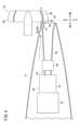
図3及び図4に示すように、排気管38の内面の後端部には、下側湾曲面50と、上側湾曲面52とが設けられている。下側湾曲面50は、図4に示すように、機体12の後方に向かって下方に傾斜するように湾曲した凸面である。上側湾曲面52は、機体12の後方に向かって下方に傾斜するように湾曲した凹面である。排気管38は、エンジン32から排出された高温の排気ガスを機体12の外部に排出する排気口54を有する。排気口54は、機体12の後方斜め下方を向いている。すなわち、排気管38は、排気ガスを機体12の後方斜め下方に向かって排出する。一対の排気口54は、機体12の中心線A1に対して左右対称に配置されている(図3参照)。3 and 4, the rear end of the inner surface of the
図2~図5に示すように、機体12の後端には、空気排出口56が設けられている。空気排出口56は、4つの冷却ファン48によって機体12の内部に取り込まれた空気を機体12の外部に排出する。すなわち、空気排出口56は、排気ガスよりも低温の空気を排出する。空気排出口56は、排気口54の外側に隣接している。As shown in Figures 2 to 5, an
図3及び図5に示すように、空気排出口56は、第1排出部58と、第2排出部60とを含む。第1排出部58は、一対の排気口54の上側に位置する。第1排出部58は、上側湾曲面52の外側に位置する。第1排出部58は、機体12の後端部と排気管38との間に設けられている。第2排出部60は、一対の排気口54の間に位置する。第2排出部60は、一対の排気管38の後端部の間に設けられている。As shown in Figures 3 and 5, the
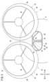
一対のクルーズロータ22は、排気口54よりも機体12の後方に位置している(図1及び図2参照)。図3に示すように、一対のクルーズロータ22は、機体12の上下方向に延びた中心線A2に対して左右対称に配置されている。一対のクルーズロータ22は、機体12の背面視で機体12に重なるように配置されている。一対のクルーズロータ22は、機体12の背面視で機体12の後端部に重なるように配置されている。これにより、一対のクルーズロータ22によって発生した推力を機体12に良好に作用させることができる。一対のクルーズロータ22は、互いに近接している。The pair of
クルーズロータ22は、プロペラ部62と、ダクト64とを有する。プロペラ部62は、クルーズモータ24の駆動によって回転する。ダクト64は、例えば、軽量な樹脂材料によって構成されている。当該樹脂材料としては、例えば、エポキシ基炭素強化プラスチック(CFRP)が挙げられる。ダクト64は、排気ガスが直接当たると、劣化し得る。ダクト64の構成材料は、樹脂材料に限定されず、金属材料であってもよい。ダクト64は、円筒状に構成されている。ダクト64は、プロペラ部62を径方向外方から覆う。The
ダクト64の外周面は、径方向外方に円弧状に膨出している。換言すれば、図4に示すように、ダクト64の外周面は、第1面部66と、第2面部68とを含む。第1面部66は、機体12の後方に向かってダクト64の外径が大きくなる部分である。第2面部68は、機体12の後方に向かってダクト64の外径が小さくなる部分である。第2面部68は、第1面部66に対して機体12の後方に位置している。第1面部66と第2面部68とは、繋がっている。The outer peripheral surface of the
図5は、航空機10を排気ガスの排出方向から見た図である。図5に示すように、排気口54とクルーズロータ22とは、排気ガスの排出方向から見て互いに重ならない。図3は、航空機10の背面図である。図3に示すように、排気口54とクルーズロータ22とは、機体12の背面視で互いに重ならないように配置されている。空気排出口56の第1排出部58とダクト64とは、機体12の背面視で互いに重なる。ダクト64の外周面は、空気排出口56から排出された空気を案内する。Figure 5 is a view of the
クルーズロータ22は、図3及び図5に仮想線で示すような位置に配置されてもよい。この場合、図3に仮想線で示すように、排気口54とクルーズロータ22とは、機体12の背面視で互いに重なる。一方、図5に仮想線で示すように、排気口54とクルーズロータ22とは、排気ガスの排出方向から見て互いに重ならない。また、空気排出口56の第1排出部58とクルーズロータ22とは、排気ガスの排出方向から見て互いに重なる。The
上述した航空機10において、エンジン32から排出された高温の排気ガスは、ガス混合部40から導入された冷却ガスによって冷却される。その後、排気ガスは、排気管38を通り排気口54から機体12の後方斜め下方に排出される。排気口54から排出された排気ガスは、ダクト64に当たらない。In the above-described
また、4つの冷却ファン48によって機体12の内部に取り込まれた空気は、機体12の内部を介して空気排出口56から機体12の後方斜め下方に向けて排出される。空気排出口56から排出された空気である排出空気は、排気口54から排出された排気ガスとクルーズロータ22のダクト64との間を流通する。つまり、排出空気は、排気ガスのクルーズロータ22への接触を抑制するためのエアーカーテンとして機能する。そのため、排気ガスの熱のクルーズロータ22への伝達が良好に抑制される。In addition, the air taken into the interior of the
図4に示すように、排出空気は、ダクト64の外周面に案内されながら流通する。換言すれば、排出空気は、ダクト64の外周面の第1面部66から第2面部68に向かって流れる。この場合、排出空気が第2面部68を流れる際に、排出空気と排気ガスの流路断面積が広がる。すなわち、ダクト64の第2面部68は、ディフューザとして機能する。これにより、排気ガスを機体12の外部に円滑に排出することができる。As shown in FIG. 4, the exhaust air flows while being guided by the outer peripheral surface of the
本実施形態によれば、排気口54とクルーズロータ22とが排気ガスの排出方向から見て互いに重ならないため、排気口54から排出された排気ガスがクルーズロータ22に当たることを抑制することができる。すなわち、本実施形態によれば、排気口54とクルーズロータ22とを良好に配置することができる。このように、本実施形態によれば、良好な航空機10を提供することができる。According to this embodiment, the
航空機10は、上述した構成に限定されない。機体12の後端部には、機体12の外部の空気を空気排出口56に導入するための空気導入口が設けられてもよい。この場合、上述した4つの冷却ユニット45の少なくとも一部は省略されてもよい。The
上述した開示に関し、さらに以下の付記を開示する。The following additional information is provided in addition to the disclosure above:
(付記1)
航空機(10)は、機体(12)と、前記機体に設けられたエンジン(32)と、前記機体の後端部に設けられて前記エンジンの排気ガスを外部に排出するための排気口(54)と、前記排気口よりも前記機体の後方に位置して前記機体に水平方向の推力を発生させるためのクルーズロータ(22)と、を備え、前記排気口と前記クルーズロータとは、前記排気ガスの排出方向から見て互いに重ならない。(Appendix 1)
The aircraft (10) comprises an airframe (12), an engine (32) mounted on the airframe, an exhaust port (54) mounted at the rear end of the airframe for discharging exhaust gas from the engine to the outside, and a cruise rotor (22) positioned rearward of the exhaust port on the airframe for generating horizontal thrust on the airframe, the exhaust port and the cruise rotor not overlapping each other when viewed from the exhaust gas discharge direction.
このような構成によれば、排気口とクルーズロータとが排気ガスの排出方向から見て互いに重ならないため、排気口から排出された排気ガスがクルーズロータに当たることを抑制することができる。すなわち、このような構成によれば、排気口とクルーズロータとを良好に配置することができる。このように、良好な航空機を提供することができる。With this configuration, the exhaust port and the cruise rotor do not overlap when viewed from the exhaust gas discharge direction, so that it is possible to prevent the exhaust gas discharged from the exhaust port from hitting the cruise rotor. In other words, with this configuration, the exhaust port and the cruise rotor can be positioned in a good manner. In this way, it is possible to provide a good aircraft.
(付記2)
付記1に記載の航空機において、前記排気口と前記クルーズロータとは、前記機体の背面視で互いに重ならなくてもよい。(Appendix 2)
In the aircraft described in Supplementary Note 1, the exhaust port and the cruise rotor do not have to overlap with each other in a rear view of the airframe.
このような構成によれば、排気ガスがクルーズロータに当たることを一層抑制することができる。This configuration further prevents exhaust gas from hitting the cruise rotor.
(付記3)
付記1又は2に記載の航空機において、前記機体の後端部のうちの前記排気口の外側に隣接する部分には、前記排気ガスよりも低温の空気を排出する空気排出口(56)が設けられていてもよい。(Appendix 3)
In the aircraft described in Supplementary Note 1 or 2, an air exhaust port (56) for discharging air at a lower temperature than the exhaust gas may be provided in a portion of the rear end of the fuselage adjacent to the outside of the exhaust port.
このような構成によれば、空気排出口から排出された空気である排出空気を、排気口から排出された排気ガスとクルーズロータとの間に流通させることができる。これにより、排気ガスの熱がクルーズロータに伝達することを排出空気によって抑えることができる。With this configuration, exhaust air, which is air discharged from the air exhaust port, can be circulated between the exhaust gas discharged from the exhaust port and the cruise rotor. This allows the exhaust air to prevent the heat of the exhaust gas from being transmitted to the cruise rotor.
(付記4)
付記3に記載の航空機において、前記クルーズロータの一部と前記空気排出口とは、前記機体の背面視で互いに重なってもよい。(Appendix 4)
In the aircraft described in Supplementary Note 3, a portion of the cruise rotor and the air exhaust port may overlap with each other in a rear view of the aircraft.
このような構成によれば、排気ガスがクルーズロータに当たることを排出空気によって抑制しつつクルーズロータによって発生した推力を機体に良好に作用させることができる。With this configuration, the exhaust air can be used to prevent exhaust gases from hitting the cruise rotor, while allowing the thrust generated by the cruise rotor to be effectively applied to the aircraft.
(付記5)
付記4に記載の航空機において、前記クルーズロータは、回転するプロペラ部(62)と、前記プロペラ部を径方向外方から覆う円筒状のダクト(64)と、を有し、前記ダクトと前記空気排出口とは、前記機体の背面視で互いに重なってもよい。(Appendix 5)
In the aircraft described in
このような構成によれば、排気空気がプロペラ部に当たることを抑制することができる。This configuration prevents exhaust air from hitting the propeller.
(付記6)
付記5に記載の航空機において、前記ダクトの外周面は、前記空気排出口から排出された前記空気を案内してもよい。(Appendix 6)
In the aircraft described in Supplementary Note 5, an outer peripheral surface of the duct may guide the air discharged from the air exhaust port.
このような構成によれば、ダクトをディフューザとして機能させることができるため、排気ガスを機体の外部に円滑に排出することができる。This configuration allows the duct to function as a diffuser, allowing exhaust gases to be smoothly discharged outside the aircraft.
(付記7)
付記3に記載の航空機において、前記機体の内部には、前記機体に推力を発生させるためのモータ(20、24)と前記モータに電力を供給する電力変換装置(42)との少なくともいずれかを冷却するためのラジエータ(46)と、前記機体の外部の空気を前記ラジエータに供給すると共に前記空気を前記機体の前記内部に取り込む冷却ファン(48)と、が設けられ、前記空気排出口は、前記冷却ファンによって前記機体の前記内部に取り込まれた前記空気を排出してもよい。(Appendix 7)
In the aircraft described in Supplementary Note 3, a radiator (46) for cooling at least one of a motor (20, 24) for generating thrust for the aircraft and a power conversion device (42) for supplying power to the motor, and a cooling fan (48) for supplying air outside the aircraft to the radiator and taking the air into the interior of the aircraft are provided inside the aircraft, and the air exhaust port may exhaust the air taken in to the interior of the aircraft by the cooling fan.
このような構成によれば、モータと電力変換装置との少なくともいずれかを冷却するための冷却ファンを流用して空気排出口から空気を排出することができる。すなわち、空気排出口から空気を排出させるためのファン等を新たに設ける必要がない。そのため、航空機の構成を簡単にできる。With this configuration, the cooling fan for cooling at least one of the motor and the power conversion device can be used to exhaust air from the air exhaust port. In other words, there is no need to install a new fan or the like for exhausting air from the air exhaust port. This simplifies the configuration of the aircraft.
(付記8)
付記1~7のいずれかに記載の航空機において、前記排気口は、前記機体の後方に向かって斜め下方に前記排気ガスを排出してもよい。(Appendix 8)
In the aircraft described in any one of Supplementary notes 1 to 7, the exhaust port may discharge the exhaust gas obliquely downward toward the rear of the aircraft.
このような構成によれば、排気ガスがクルーズロータに当たることをより一層抑制することができる。This configuration further prevents exhaust gas from hitting the cruise rotor.
(付記9)
付記1~8のいずれかに記載の航空機において、前記排気口は、前記機体の左右方向に一対配置され、前記クルーズロータは、前記機体の前記左右方向に一対配置されてもよい。(Appendix 9)
In the aircraft described in any one of Supplementary notes 1 to 8, the exhaust ports may be arranged in a pair in the left-right direction of the aircraft, and the cruise rotors may be arranged in a pair in the left-right direction of the aircraft.
このような構成によれば、クルーズロータによって発生した推力を機体にバランスよく作用させることができる。This configuration allows the thrust generated by the cruise rotor to be applied to the aircraft in a balanced manner.
(付記10)
航空機は、機体と、前記機体に設けられたエンジンと、前記機体の後端部に設けられて前記エンジンの排気ガスを外部に排出するための排気口と、前記排気口よりも前記機体の後方に位置して前記機体に水平方向の推力を発生させるためのクルーズロータと、を備え、前記排気口と前記クルーズロータとは、前記機体の背面視で互いに重ならないように配置されている。(Appendix 10)
The aircraft comprises an aircraft body, an engine mounted on the aircraft body, an exhaust port mounted at the rear end of the aircraft for discharging exhaust gas from the engine to the outside, and a cruise rotor positioned rearward of the exhaust port on the aircraft for generating horizontal thrust on the aircraft, the exhaust port and the cruise rotor being positioned so as not to overlap each other when viewed from the rear of the aircraft.
このような構成によれば、排気口とクルーズロータとが機体の背面視で互いに重ならないため、排気口から排出された排気ガスがクルーズロータに当たることを抑制することができる。すなわち、排気口とクルーズロータとを良好に配置することができる。このように、良好な航空機を提供することができる。With this configuration, the exhaust port and the cruise rotor do not overlap when viewed from the rear of the aircraft, so that the exhaust gas discharged from the exhaust port can be prevented from hitting the cruise rotor. In other words, the exhaust port and the cruise rotor can be positioned in a good manner. In this way, a good aircraft can be provided.
なお、本発明は、上述した開示に限らず、本発明の要旨を逸脱することなく、種々の構成を採り得る。The present invention is not limited to the above disclosure, and various configurations may be adopted without departing from the gist of the present invention.
10…航空機 12…機体
18…VTOLロータ 20…VTOLモータ
22…クルーズロータ 24…クルーズモータ
32…エンジン 42…電力変換装置
46…ラジエータ 48…冷却ファン
54…排気口 56…空気排出口
62…プロペラ部 64…ダクトREFERENCE SIGNS LIST 10
Claims (10)
Translated fromJapanese前記機体に設けられたエンジンと、
前記機体の後端部に設けられて前記エンジンの排気ガスを外部に排出するための排気口と、
前記排気口よりも前記機体の後方に位置して前記機体に水平方向の推力を発生させるためのクルーズロータと、
を備え、
前記排気口と前記クルーズロータとは、前記排気ガスの排出方向から見て互いに重ならない、航空機。 The aircraft and
An engine provided on the airframe;
an exhaust port provided at a rear end of the aircraft body for discharging exhaust gas from the engine to the outside;
a cruise rotor located rearward of the airframe relative to the exhaust port for generating horizontal thrust on the airframe;
Equipped with
An aircraft, wherein the exhaust port and the cruise rotor do not overlap with each other when viewed from a direction in which the exhaust gas is discharged.
前記排気口と前記クルーズロータとは、前記機体の背面視で互いに重ならない、航空機。 2. The aircraft of claim 1,
an exhaust port and a cruise rotor that do not overlap with each other in a rear view of the aircraft;
前記機体の後端部のうちの前記排気口の外側に隣接する部分には、前記排気ガスよりも低温の空気を排出する空気排出口が設けられている、航空機。 2. The aircraft of claim 1,
An aircraft, wherein an air exhaust port is provided at a portion of the rear end of the fuselage adjacent to the outside of the exhaust port, the air exhaust port discharging air having a lower temperature than the exhaust gas.
前記クルーズロータの一部と前記空気排出口とは、前記機体の背面視で互いに重なる、航空機。 4. An aircraft as claimed in claim 3,
An aircraft, wherein a portion of the cruise rotor and the air exhaust port overlap each other in a rear view of the aircraft.
前記クルーズロータは、
回転するプロペラ部と、
前記プロペラ部を径方向外方から覆う円筒状のダクトと、
を有し、
前記ダクトと前記空気排出口とは、前記機体の背面視で互いに重なる、航空機。 5. An aircraft as claimed in claim 4,
The cruise rotor is
A rotating propeller part;
A cylindrical duct that covers the propeller portion from the outside in the radial direction;
having
The duct and the air exhaust port overlap each other in a rear view of the aircraft.
前記ダクトの外周面は、前記空気排出口から排出された前記空気を案内する、航空機。 6. An aircraft as claimed in claim 5,
The outer peripheral surface of the duct guides the air discharged from the air exhaust port.
前記機体の内部には、
前記機体に推力を発生させるためのモータと前記モータに電力を供給する電力変換装置との少なくともいずれかを冷却するためのラジエータと、
前記機体の外部の空気を前記ラジエータに供給すると共に前記空気を前記機体の前記内部に取り込む冷却ファンと、
が設けられ、
前記空気排出口は、前記冷却ファンによって前記機体の前記内部に取り込まれた前記空気を排出する、航空機。 4. An aircraft as claimed in claim 3,
Inside the aircraft,
a radiator for cooling at least one of a motor for generating thrust on the airframe and a power conversion device for supplying power to the motor;
a cooling fan that supplies air outside the aircraft body to the radiator and takes the air into the interior of the aircraft body;
was established,
The air exhaust port exhausts the air taken into the interior of the aircraft by the cooling fan.
前記排気口は、前記機体の後方に向かって斜め下方に前記排気ガスを排出する、航空機。 An aircraft according to any one of claims 1 to 7,
The exhaust port discharges the exhaust gas obliquely downward toward the rear of the aircraft.
前記排気口は、前記機体の左右方向に一対配置され、
前記クルーズロータは、前記機体の前記左右方向に一対配置されている、航空機。 An aircraft according to any one of claims 1 to 7,
The exhaust ports are arranged in a pair in the left-right direction of the airframe,
An aircraft, wherein the cruise rotors are arranged in pair in the left-right direction of the airframe.
前記機体に設けられたエンジンと、
前記機体の後端部に設けられて前記エンジンの排気ガスを外部に排出するための排気口と、
前記排気口よりも前記機体の後方に位置して前記機体に水平方向の推力を発生させるためのクルーズロータと、
を備え、
前記排気口と前記クルーズロータとは、前記機体の背面視で互いに重ならないように配置されている、航空機。 The aircraft and
An engine provided on the airframe;
an exhaust port provided at a rear end of the aircraft body for discharging exhaust gas from the engine to the outside;
a cruise rotor located rearward of the airframe relative to the exhaust port for generating horizontal thrust on the airframe;
Equipped with
An aircraft, wherein the exhaust port and the cruise rotor are arranged so as not to overlap with each other in a rear view of the aircraft.
Priority Applications (3)
| Application Number | Priority Date | Filing Date | Title |
|---|---|---|---|
| JP2023055319AJP2024142914A (en) | 2023-03-30 | 2023-03-30 | aircraft |
| US18/621,710US12420942B2 (en) | 2023-03-30 | 2024-03-29 | Aircraft |
| CN202410372326.0ACN118723093A (en) | 2023-03-30 | 2024-03-29 | Aircraft |
Applications Claiming Priority (1)
| Application Number | Priority Date | Filing Date | Title |
|---|---|---|---|
| JP2023055319AJP2024142914A (en) | 2023-03-30 | 2023-03-30 | aircraft |
Publications (1)
| Publication Number | Publication Date |
|---|---|
| JP2024142914Atrue JP2024142914A (en) | 2024-10-11 |
Family
ID=92859002
Family Applications (1)
| Application Number | Title | Priority Date | Filing Date |
|---|---|---|---|
| JP2023055319APendingJP2024142914A (en) | 2023-03-30 | 2023-03-30 | aircraft |
Country Status (3)
| Country | Link |
|---|---|
| US (1) | US12420942B2 (en) |
| JP (1) | JP2024142914A (en) |
| CN (1) | CN118723093A (en) |
Family Cites Families (10)
| Publication number | Priority date | Publication date | Assignee | Title |
|---|---|---|---|---|
| US3907219A (en)* | 1972-10-16 | 1975-09-23 | Jack W Pharris | High speed, long range turbo-jet aircraft |
| FR2929243B1 (en)* | 2008-03-25 | 2010-04-23 | Eurocopter France | RAPID HYBRID HELICOPTER WITH EXTENDABLE HIGH DISTANCE |
| US10273018B2 (en) | 2012-10-10 | 2019-04-30 | Sikorsky Aircraft Corporation | Upturned exhaust system for rotary wing aircraft |
| US10562641B2 (en) | 2012-10-10 | 2020-02-18 | Sikorsky Aircraft Corporation | AFT exhaust system for rotary wing aircraft |
| CN107074358B (en)* | 2014-05-07 | 2020-01-07 | Xti飞行器公司 | vertical take-off and landing aircraft |
| FR3042010B1 (en)* | 2015-10-05 | 2018-07-13 | Safran Aircraft Engines | AIRCRAFT WITH A MULTI-BLOWING PROPULSIVE ASSEMBLY FIXED UNDER AILE |
| US10823041B2 (en)* | 2017-12-19 | 2020-11-03 | Pratt & Whitney Canada Corp. | Engine assembly with plenum and remote fan |
| US10773817B1 (en)* | 2018-03-08 | 2020-09-15 | Northrop Grumman Systems Corporation | Bi-directional flow ram air system for an aircraft |
| US11267579B2 (en)* | 2019-03-26 | 2022-03-08 | Textron Innovations Inc. | Compound helicopters having hybrid propulsion engines |
| US12158103B1 (en)* | 2023-06-26 | 2024-12-03 | Pratt & Whitney Canada Corp. | Cooling flow injection to alter exhaust boundary conditions in a turbo-compounded engine |
- 2023
- 2023-03-30JPJP2023055319Apatent/JP2024142914A/enactivePending
- 2024
- 2024-03-29USUS18/621,710patent/US12420942B2/enactiveActive
- 2024-03-29CNCN202410372326.0Apatent/CN118723093A/enactivePending
Also Published As
| Publication number | Publication date |
|---|---|
| US20240327016A1 (en) | 2024-10-03 |
| US12420942B2 (en) | 2025-09-23 |
| CN118723093A (en) | 2024-10-01 |
Similar Documents
| Publication | Publication Date | Title |
|---|---|---|
| CN110034636B (en) | Cooling system for electric aircraft engine | |
| US11867121B2 (en) | Gas turbine engines with heat recovery systems | |
| EP1427926B1 (en) | Rotary heat engine | |
| JP6188836B2 (en) | Aircraft having a fuselage that defines at least an internal area and a drive system accommodation area | |
| US20120086217A1 (en) | Power Generation Apparatus | |
| CN114845933A (en) | Propulsion system for an aircraft, the propulsion system including a fuel cell | |
| CN107636258A (en) | gas turbine engine | |
| CN201466886U (en) | Open frame type digital generator | |
| US2631429A (en) | Cooling arrangement for radial flow gas turbines having coaxial combustors | |
| US20220298970A1 (en) | Gas turbine system | |
| JP2024142914A (en) | aircraft | |
| US20220055759A1 (en) | Propulsion engine assemblies providing access to components within propulsor cavities | |
| JP2020083062A (en) | Power supply device and air vehicle | |
| GB2599726A (en) | Air cooling | |
| US20250083790A1 (en) | System for the thermal management of an external electric-power-generating nacelle equipping an electrically powered airship, nacelle and airship equipped with said system | |
| JP2020083060A (en) | Power supply device | |
| US12441480B2 (en) | Aircraft | |
| US20240327020A1 (en) | Aircraft | |
| CN115694073A (en) | Electric motor car motor heat radiation structure | |
| JP7519791B2 (en) | Power supply unit and flying object | |
| US12241381B2 (en) | Gas mixing device and moving object | |
| JP7305472B2 (en) | GAS TURBINE SYSTEM AND MOVING OBJECT WITH THE SAME | |
| CN215333122U (en) | Cooling air duct of variable frequency generator | |
| CN204646419U (en) | The air flue structure of generator set and vehicle-based generator set | |
| CZ2007415A3 (en) | Electric motor with rotary jacket intended for both industrial and modelerÆs applications |