JP2024140866A - Mobile beacon terminal and entrance/exit management system - Google Patents
Mobile beacon terminal and entrance/exit management systemDownload PDFInfo
- Publication number
- JP2024140866A JP2024140866AJP2023052217AJP2023052217AJP2024140866AJP 2024140866 AJP2024140866 AJP 2024140866AJP 2023052217 AJP2023052217 AJP 2023052217AJP 2023052217 AJP2023052217 AJP 2023052217AJP 2024140866 AJP2024140866 AJP 2024140866A
- Authority
- JP
- Japan
- Prior art keywords
- management
- beacon
- terminal
- entrance
- storage battery
- Prior art date
- Legal status (The legal status is an assumption and is not a legal conclusion. Google has not performed a legal analysis and makes no representation as to the accuracy of the status listed.)
- Pending
Links
Images


Landscapes
- Secondary Cells (AREA)
- Near-Field Transmission Systems (AREA)
- Charge And Discharge Circuits For Batteries Or The Like (AREA)
Abstract
Translated fromJapaneseDescription
Translated fromJapanese本開示は一般に携帯ビーコン端末及び入退管理システムに関し、より詳細には、蓄電池の電力を用いてビーコン信号を送信する携帯ビーコン端末、及び、この携帯ビーコン端末を備える入退管理システムに関する。This disclosure generally relates to a portable beacon terminal and an access control system, and more specifically, to a portable beacon terminal that transmits a beacon signal using power from a storage battery, and an access control system that includes this portable beacon terminal.
特許文献1に記載の非接触型ICカード(携帯ビーコン端末)は、カード基板と、近距離無線通信機と、ビーコン発信機と、アンテナと、電池と、を備える。アンテナは、ビーコン発信機からのビーコン信号を放射する。電池は、少なくともビーコン発信機に電力を供給する。また、特許文献1に記載のICカード利用システムは、ビーコン信号の受信に基づいて、非接触型ICカードを携帯するユーザの認証と、ユーザの位置情報の取得と、を行う。The contactless IC card (portable beacon terminal) described in Patent Document 1 includes a card board, a short-range wireless communication device, a beacon transmitter, an antenna, and a battery. The antenna emits a beacon signal from the beacon transmitter. The battery supplies power to at least the beacon transmitter. The IC card usage system described in Patent Document 1 authenticates a user carrying a contactless IC card and obtains the user's location information based on the reception of the beacon signal.
しかしながら、特許文献1に記載の非接触型ICカード(携帯ビーコン端末)では、電池(蓄電池)の残容量が低下したことにユーザが気付かない可能性がある。その結果として、電池の残容量が低下して、ビーコン発信機がビーコン信号を発信できなくなり、ユーザの入退管理(認証)及び居場所特定(位置情報の取得)ができない状態となるおそれがある。However, with the non-contact IC card (portable beacon terminal) described in Patent Document 1, there is a possibility that the user will not notice that the remaining capacity of the battery (storage battery) is decreasing. As a result, the remaining capacity of the battery may decrease, causing the beacon transmitter to be unable to transmit a beacon signal, which may result in a state in which it is no longer possible to manage the entry and exit of users (authentication) or to identify their location (acquisition of location information).
本開示は、蓄電池の残容量の低下によって携帯ビーコン端末がビーコン信号を送信することができなくなる可能性を低減させることを目的とする。The present disclosure aims to reduce the possibility that a portable beacon terminal will be unable to transmit a beacon signal due to a decrease in the remaining capacity of a storage battery.
本開示の一態様に係る携帯ビーコン端末は、ビーコン送信部と、ビーコン制御部と、導電部材と、入退管理器と、電磁充電部と、残容量検出部と、を備える。前記ビーコン送信部は、ビーコン信号を送信する。前記ビーコン制御部は、前記ビーコン送信部を制御する。前記導電部材は、蓄電池に電気的に接続される。前記蓄電池は、前記ビーコン送信部及び前記ビーコン制御部に電源電力を供給する。前記入退管理器は、NFCアンテナと、入退管理制御部と、を有する。前記NFCアンテナは、管理端末から磁界が印加されたときに誘導起電力を発生する。前記入退管理制御部は、前記NFCアンテナで発生する前記誘導起電力を電源電力として用いて、入退管理に関する入退管理情報を含む信号を前記管理端末へ、前記NFCアンテナを介した近距離無線通信により送信する。前記電磁充電部は、前記管理端末から印加される磁界を用いた電磁誘導方式のワイヤレス給電により、前記蓄電池を充電する。前記残容量検出部は、前記蓄電池の残容量を検出する。前記入退管理制御部は、前記残容量検出部で検出された前記残容量が閾値よりも小さくなったときに、前記蓄電池の充電要請を含む信号を前記管理端末へ、前記NFCアンテナを介した近距離無線通信により送信する。A portable beacon terminal according to one aspect of the present disclosure includes a beacon transmitter, a beacon control unit, a conductive member, an entrance/exit management device, an electromagnetic charging unit, and a remaining capacity detection unit. The beacon transmitter transmits a beacon signal. The beacon control unit controls the beacon transmitter. The conductive member is electrically connected to a storage battery. The storage battery supplies power to the beacon transmitter and the beacon control unit. The entrance/exit management device has an NFC antenna and an entrance/exit management control unit. The NFC antenna generates an induced electromotive force when a magnetic field is applied from a management terminal. The entrance/exit management control unit uses the induced electromotive force generated by the NFC antenna as power supply to transmit a signal including entrance/exit management information related to entrance/exit management to the management terminal by short-range wireless communication via the NFC antenna. The electromagnetic charging unit charges the storage battery by wireless power supply using an electromagnetic induction method using a magnetic field applied from the management terminal. The remaining capacity detection unit detects the remaining capacity of the storage battery. When the remaining capacity detected by the remaining capacity detection unit becomes smaller than a threshold value, the entry/exit management control unit transmits a signal including a request to charge the storage battery to the management terminal by short-range wireless communication via the NFC antenna.
本開示の一態様に係る入退管理システムは、前記携帯ビーコン端末と、管理システムと、を備える。前記管理システムは、前記管理端末を含む。前記管理端末は、通信器と、充電コイルと、報知部と、を有する。前記通信器は、管理側NFCアンテナを含む。前記通信器は、前記携帯ビーコン端末の前記入退管理器と近距離無線通信をする。前記充電コイルは、前記携帯ビーコン端末の前記電磁充電部に対して、前記蓄電池を充電するための磁界を印加する。前記報知部は、前記携帯ビーコン端末の前記蓄電池の前記残容量が閾値よりも小さくなったことをユーザに報知する。前記管理システムは、前記管理端末の前記通信器が前記携帯ビーコン端末から、前記蓄電池の前記充電要請を含む信号を受信した場合に、前記報知部に所定の報知をさせる。The entrance/exit management system according to one aspect of the present disclosure includes the mobile beacon terminal and a management system. The management system includes the management terminal. The management terminal has a communicator, a charging coil, and an alarm unit. The communicator includes a management-side NFC antenna. The communicator performs short-range wireless communication with the front-entry/exit management device of the mobile beacon terminal. The charging coil applies a magnetic field to the electromagnetic charging unit of the mobile beacon terminal to charge the storage battery. The alarm unit notifies a user that the remaining capacity of the storage battery of the mobile beacon terminal has become smaller than a threshold value. The management system causes the alarm unit to issue a predetermined alarm when the communicator of the management terminal receives a signal including the request to charge the storage battery from the mobile beacon terminal.
本開示は、蓄電池の残容量の低下によって携帯ビーコン端末がビーコン信号を送信することができなくなる可能性を低減させることができる、という利点がある。The present disclosure has the advantage of reducing the possibility that a portable beacon terminal will be unable to transmit a beacon signal due to a decrease in the remaining capacity of the storage battery.
(実施形態)
以下、実施形態に係る携帯ビーコン端末1及び入退管理システム100について、図面を用いて説明する。ただし、下記の実施形態は、本開示の様々な実施形態の1つに過ぎない。下記の実施形態は、本開示の目的を達成できれば、設計等に応じて種々の変更が可能である。 (Embodiment)
The following describes the portable beacon terminal 1 and the entrance/
(概要)
図1に示すように、入退管理システム100は、少なくとも1つの携帯ビーコン端末1と、管理システム101と、を備える。管理システム101は、施設に設置され、ユ―ザの認証を行う。この認証は、ユーザが所持する携帯ビーコン端末1を用いてなされる認証であって、ユーザが施設の特定のエリアへの入域、及び、特定のエリアからの退域の少なくとも一方を行うための認証である。携帯ビーコン端末1から出力される信号に含まれた管理ID(入退管理情報)が、管理システム101に予め登録されている場合は、認証結果は「認証成功」を含み、管理IDが管理システム101に予め登録されていない場合は、認証結果は「認証失敗」を含む。また、認証結果が「認証成功」を含む場合は、認証結果は、「入域許可」又は「入域不許可」を更に含む。すなわち、管理システム101は、管理IDと、特定のエリアへの「入域許可」又は「入域不許可」と、を紐付ける情報を予め記憶しており、当該情報に基づいて「入域許可」又は「入域不許可」を選択する。 (overview)
As shown in FIG. 1, the entrance/
認証結果が「認証成功」かつ「入域許可」の場合、管理システム101は、例えばゲート26(特定のエリアの出入り口に設置され、出入り口を塞ぐ位置と出入り口を開放する位置との間を移動する器具)を解錠する。これにより、ユーザは特定のエリアに対して入域及び退域可能となる。一方で、認証結果が「認証失敗」又は、「認証成功」かつ「入域不許可」の場合、管理システム101は、例えばゲート26を解錠しない(施錠状態を維持する)。これにより、ユーザは特定のエリアに対して入域及び退域不可能となる。ユーザは、管理IDにより識別されて、管理システム101は、ユーザごとの(つまり、管理IDごとの)認証結果を生成し、記憶する。If the authentication result is "authentication successful" and "entry permitted", the
特定のエリアは、例えば、施設の出入り口付近のエリア、施設内の建物の出入り口付近のエリア、又は、建物内の部屋である。施設は、例えば、オフィス又は工場等である。本実施形態では、施設がオフィスであることを想定して説明する。その他、施設は、住宅、店舗、複合商業施設、図書館、美術館、博物館、遊戯施設、テーマパーク、公園、空港、鉄道駅、球場、ホテル、病院又は住宅等であってもよい。また、施設は、例えば、船舶又は鉄道車両等の移動体であってもよい。施設は、屋内施設であってもよいし、屋外施設であってもよい。The specific area is, for example, an area near the entrance of a facility, an area near the entrance of a building within the facility, or a room within a building. The facility is, for example, an office or a factory. In this embodiment, the description will be given assuming that the facility is an office. Alternatively, the facility may be a house, a store, a commercial complex, a library, an art gallery, a museum, an amusement facility, a theme park, a park, an airport, a train station, a stadium, a hotel, a hospital, or a house. The facility may also be a mobile object such as a ship or a railroad car. The facility may be an indoor facility or an outdoor facility.
また、携帯ビーコン端末1は、ビーコン信号B1を発信する。管理システム101は、ビーコン信号B1に基づいて、携帯ビーコン端末1の位置情報を求める。携帯ビーコン端末1の位置情報は、携帯ビーコン端末1を所持するユーザの位置情報に相当する。ビーコン信号B1は、ビーコンIDを含んでおり、管理システム101は、ユーザごとの(つまり、ビーコンIDと対応付けられた携帯ビーコン端末1ごとの)位置情報を求め、記憶する。The portable beacon terminal 1 also transmits a beacon signal B1. The
管理システム101は、ユーザの認証結果と、ユーザの位置情報と、を記憶する。管理システム101を使用する者(例えば、ユーザの雇用主又は上司等の管理者)は、管理システム101に記憶された情報を用いて、ユーザの行動管理及び勤怠管理、並びに、ユーザの所在の把握等をすることができる。The
図1に示すように、本実施形態の携帯ビーコン端末1は、ビーコン送信部2と、ビーコン制御部3と、導電部材4a、4bと、入退管理器5と、電磁充電部6と、残容量検出部7と、を備える。ビーコン送信部2は、ビーコン信号B1を送信する。ビーコン制御部3は、ビーコン送信部2を制御する。導電部材4a、4bは、蓄電池4に電気的に接続される。蓄電池4は、ビーコン送信部2及びビーコン制御部3に電源電力を供給する。入退管理器5は、NFC(Near Field Communication)アンテナ8と、入退管理制御部9と、を有する。NFCアンテナ8は、管理端末11から磁界M1が印加されたときに誘導起電力を発生する。入退管理制御部9は、NFCアンテナ8で発生する誘導起電力を電源電力として用いて、入退管理に関する入退管理情報を含む信号を管理端末11へ、NFCアンテナ8を介した近距離無線通信により送信する。電磁充電部6は、管理端末11から印加される磁界M2を用いた電磁誘導方式のワイヤレス給電により、蓄電池4を充電する。残容量検出部7は、蓄電池4の残容量を検出する。入退管理制御部9は、残容量検出部7で検出された残容量が閾値よりも小さくなったときに、蓄電池4の充電要請を含む信号を管理端末11へ、NFCアンテナ8を介した近距離無線通信により送信する。As shown in FIG. 1, the portable beacon terminal 1 of this embodiment includes a
本実施形態によれば、ユーザは、携帯ビーコン端末1を所持して管理端末11に近付いたときに、蓄電池4を充電することができる。しかも、管理端末11は、入退管理情報を含む信号の送信先であるから、ユーザはある程度の頻度で、管理端末11が設置された場所に立ち入ることになる。つまり、蓄電池4を充電する機会が、ある程度の頻度で確保される。よって、蓄電池4の残容量の低下によって携帯ビーコン端末1がビーコン信号B1を送信することができなくなる可能性を低減できる。According to this embodiment, a user carrying a portable beacon terminal 1 can charge the
また、本実施形態の入退管理システム100は、携帯ビーコン端末1と、管理システム101と、を備える。管理システム101は、管理端末11を含む。管理端末11は、通信器16と、充電コイル17と、報知部18と、を有する。通信器16は、管理側NFCアンテナ16aを含む。通信器16は、携帯ビーコン端末1の入退管理器5と近距離無線通信をする。充電コイル17は、携帯ビーコン端末1の電磁充電部6に対して、蓄電池4を充電するための磁界M2を印加する。報知部18は、携帯ビーコン端末1の蓄電池4の残容量が閾値よりも小さくなったことをユーザに報知する。管理システム101は、管理端末11の通信器16が携帯ビーコン端末1から、蓄電池4の充電要請を含む信号を受信した場合に、報知部18に所定の報知をさせる。The entrance/
本実施形態の入退管理システム100によれば、ユーザは、携帯ビーコン端末1を管理端末11に近接、又は接触させて、所定の報知があったときに、蓄電池4の残容量が閾値よりも小さくなったことを知ることができる。よって、ユーザは、充電が完了するまで待機する等の行動を取ることができる。According to the entrance/
(詳細)
(1)全体構成
以下では、本実施形態の構成について、より詳細に説明する。 (detail)
(1) Overall Configuration The configuration of this embodiment will be described in more detail below.
図1に示すように、入退管理システム100は、携帯ビーコン端末1と、管理システム101と、複数(例えば、10個、20個、又はそれ以上)のビーコン受信部21と、を備える。管理システム101は、複数(例えば、数個、10個、又はそれ以上)の管理端末11と、管理装置15と、を含む。As shown in FIG. 1, the entrance/
管理システム101及び複数のビーコン受信部21は、施設に設置されている。また、施設には、複数(例えば、数個、10個、又はそれ以上)のゲート26が更に設置されている。施設を利用するユーザは、携帯ビーコン端末1を所持する。例えば、1人のユーザにつき1つ以上の携帯ビーコン端末1が所持されている。The
管理装置15は、複数の管理端末11と通信する。そのため、管理装置15と複数の管理端末11とは、各々で取得された情報を相互に参照可能である。The
管理装置15は、複数の管理端末11を制御する。さらに、管理装置15は、複数の管理端末11及び複数のビーコン受信部21から取得した情報に基づいて情報処理を行う。The
複数の管理端末11の各々は、近くに存在する携帯ビーコン端末1と、近距離無線通信により通信する。また、複数の管理端末11の各々は、携帯ビーコン端末1の蓄電池4を、ワイヤレス給電により充電する。Each of the
携帯ビーコン端末1は、蓄電池4の電力を電源電力として用いて、ビーコン信号B1を送信する。ビーコン信号B1は、複数のビーコン受信部21で受信される。また、携帯ビーコン端末1は、複数の管理端末11のうち、携帯ビーコン端末1の近くに存在する管理端末11と、近距離無線通信により通信する。The portable beacon terminal 1 transmits a beacon signal B1 using the power of the
(2)携帯ビーコン端末
携帯ビーコン端末1は、例えば、IC(Integrated Circuit)カードである。図1に示すように、携帯ビーコン端末1は、ビーコン送信部2と、ビーコン制御部3と、第1メモリ25と、入退管理器5と、を備える。入退管理器5は、NFCアンテナ8と、入退管理制御部9と、第2メモリ10と、を有する。また、携帯ビーコン端末1は、残容量検出部7と、導電部材4a、4bと、蓄電池4と、電磁充電部6と、を更に備える。電磁充電部6は、コイル12と、共振用コンデンサ13と、整流器14と、を有する。 (2) Portable beacon terminal The portable beacon terminal 1 is, for example, an IC (Integrated Circuit) card. As shown in FIG. 1, the portable beacon terminal 1 includes a
ビーコン送信部2は、ビーコン信号B1を送信する通信回路を有する。ビーコン信号B1は、電波信号である。ビーコン送信部2がビーコン信号B1を送信するために、例えば、Bluetooth(登録商標) Low Energy、又はWiFi(登録商標)等の通信方式が採用されている。The
携帯ビーコン端末1は、例えば、第1のICチップを含む。ビーコン制御部3は、第1のICチップのうち情報処理を行う回路部分である。第1メモリ25は、第1のICチップのメモリである。The portable beacon terminal 1 includes, for example, a first IC chip. The
ビーコン制御部3は、ビーコン送信部2の動作を制御する。ビーコン送信部2は、ビーコン制御部3の制御に基づいて、例えば、断続的にビーコン信号B1を送信する。The
第1メモリ25は、不揮発性の記憶装置である。第1メモリ25は、ビーコンIDを記憶している。ビーコンIDは、携帯ビーコン端末1ごとに固有のIDである。つまり、携帯ビーコン端末1の1台ごとにビーコンIDが決められている。ビーコン送信部2は、ビーコン制御部3が第1メモリ25から読み出したビーコンIDを含むビーコン信号B1を送信する。The
入退管理器5は、例えば、第2のICチップを含む。入退管理制御部9は、第2のICチップのうち情報処理を行う回路部分である。第2メモリ10は、第2のICチップのメモリである。NFCアンテナ8は、第2のICチップに接続されている。The entrance/
入退管理器5のNFCアンテナ8は、ループ状に形成された、いわゆるアンテナコイルである。NFCアンテナ8に磁界M1が印加されると、NFCアンテナ8に誘導起電力が発生する。入退管理制御部9は、NFCアンテナ8で発生する誘導起電力を電源電力として用いて動作する。入退管理制御部9は、NFCアンテナ8を介して、管理端末11と通信する。The
第2メモリ10は、不揮発性の記憶装置である。第2メモリ10は、管理IDを記憶している。管理IDは、携帯ビーコン端末1ごとに固有のIDである。つまり、携帯ビーコン端末1の1台ごとに管理IDが決められている。入退管理制御部9は、第2メモリ10から読み出した管理IDを含む信号を、管理端末11へ送信する。管理IDは、上述の入退管理情報に相当する。The
蓄電池4は、ビーコン送信部2及びビーコン制御部3に電源電力を供給する。蓄電池4は、導電部材4a、4bを介して、電磁充電部6の2次側に接続されている。導電部材4a、4bは、例えば、携帯ビーコン端末1の電気回路を構成する配線の一部である。導電部材4aは高電位側の配線の一部、導電部材4bは低電位側の配線の一部である。なお、導電部材4a、4bは、例えば、端子であってもよい。The
残容量検出部7は、例えば、電圧センサ70を含む。電圧センサ70は、導電部材4a、4bを介して、蓄電池4の正極と負極とに接続されている。電圧センサ70は、蓄電池4の出力電圧を検出する。電圧センサ70で検出された出力電圧の情報は、ビーコン制御部3に入力される。ビーコン制御部3は、電圧センサ70で検出された出力電圧に基づいて、蓄電池4の残容量を求める(推定する)。ビーコン制御部3で求められた残容量は、第1メモリ25に記憶される。ビーコン制御部3は、例えば、定期的に残容量を求める。The remaining
電磁充電部6において、共振用コンデンサ13は、コイル12と並列に接続されている。また、コイル12は、整流器14の1次側に接続されている。本実施形態の整流器14は、全波整流器である。ただし、整流器14は、半波整流器であってもよい。In the
コイル12に磁界M2が印加されると、コイル12に誘導起電力が発生する。この誘導起電力に基づく電流は、整流器14で整流されて、蓄電池4に入力される。したがって、蓄電池4が充電される。When a magnetic field M2 is applied to the
(3)管理端末
施設には、複数の管理端末11が設置される。各管理端末11は、ユーザの入退状況を監視するために設置される。各管理端末11は、例えば、施設の出入り口に設置された入場ゲート(ゲート26)の付近、施設内の建物の出入り口付近、又は、建物内の部屋の出入り口付近に設置される。各管理端末11は、管理装置15と通信する。各管理端末11は、管理装置15の管理制御部20により制御される。 (3) Management Terminal A plurality of
図1に示すように、管理端末11は、通信器16と、充電コイル17と、報知部18と、認証出力部19と、を有する。As shown in FIG. 1, the
通信器16は、管理側NFCアンテナ16aを備える。管理側NFCアンテナ16aは、ループ状に形成された、いわゆるアンテナコイルである。管理側NFCアンテナ16aは、携帯ビーコン端末1のNFCアンテナ8に磁界M1を印加する。管理端末11と、携帯ビーコン端末1の入退管理器5とは、管理端末11の管理側NFCアンテナ16aと、入退管理器5のNFCアンテナ8とを介して、近距離無線通信を行う。The
充電コイル17は、管理装置15の管理制御部20により、通電状態と、非通電状態とが切り替えられる。充電コイル17は、通電状態では、磁界M2を発生する。The charging
蓄電池4への充電要請を含む信号を通信器16が受信すると、報知部18は、管理制御部20の制御に基づいて、所定の報知をする。所定の報知は、蓄電池4の残容量が閾値よりも小さくなったことをユーザに知らせるための報知である。所定の報知がされることにより、携帯ビーコン端末1を所持するユーザは、充電が必要であることを知ることができる。携帯ビーコン端末1のビーコン制御部3は、例えば、残容量が閾値よりも小さくなると、NFCアンテナ8を介して、充電要請を含む信号を管理端末11へ送信する。報知部18は、例えば、音により、残容量が閾値よりも小さくなったことを報知する。より詳細には、報知部18は、例えば、スピーカを含み、音声により残容量が閾値よりも小さくなったことを報知する。When the
管理システム101により、ユーザの認証が行われる。認証出力部19は、管理制御部20の制御に基づいて、ユ―ザの認証結果をユーザに報知する。認証出力部19は、例えば、認証結果を、視覚的に報知する。より詳細には、認証出力部19は、例えば、2つの表示灯を含み、いずれかの表示灯を点灯させることにより、認証結果を報知する。具体例として、認証結果が「認証成功」かつ「入域許可」の場合、認証出力部19は、発光色が緑色の表示灯を点灯させ、認証結果が「認証失敗」又は、「認証成功」かつ「入域不許可」の場合、認証出力部19は、発光色が赤色の表示灯を点灯させる。The
また、管理システム101は、携帯ビーコン端末1から管理端末11が取得した管理ID(入退管理情報)を用いてのユーザの認証に成功してから、充電コイル17に、蓄電池4を充電するための磁界M2を発生させる。In addition, after the
(4)管理装置
管理装置15は、1以上のプロセッサ及びメモリを有するコンピュータシステムを含んでいる。コンピュータシステムのメモリに記録されたプログラムを、コンピュータシステムのプロセッサが実行することにより、管理装置15の少なくとも一部の機能が実現される。プログラムは、メモリに記録されていてもよいし、インターネット等の電気通信回線を通して提供されてもよく、コンピュータシステムで読み取り可能なメモリカード等の非一時的記録媒体に記録されて提供されてもよい。 (4) Management Device The
管理装置15は、複数の管理端末11を制御する。また、管理装置15は、複数の管理端末11及び複数のビーコン受信部21の各々から集めた情報に対して、情報処理を行う。The
図1に示すように、管理装置15は、管理制御部20と、メモリ23と、入力IF(インタフェース)24と、出力IF(インタフェース)22と、を有する。As shown in FIG. 1, the
管理制御部20は、管理装置15の1以上のプロセッサを含む構成である。管理制御部20は、情報処理を行う。また、管理制御部20は、メモリ23におけるデータの読み出し及び書き込み、並びに、入力IF24及び出力IF22の制御を行う。また、管理制御部20は、複数の管理端末11の制御を行う。The
メモリ23は、データを記憶する。例えば、メモリ23は、管理制御部20が複数のビーコン受信部21から取得した情報に基づいて求めた、携帯ビーコン端末1の位置情報を記憶する。また、メモリ23は、複数のビーコン受信部21の位置情報を記憶する。また、メモリ23は、管理制御部20によるユーザの認証結果を記憶する。The
入力IF24は、人の操作を受け付ける。入力IF24は、例えば、人の手動操作を受け付けるための、マウス、釦、キーボード、キースイッチ、タッチパッド、タッチパネル及びタッチパネルディスプレイのうち少なくとも1つを有する。なお、入力IF24は、例えば、音声操作を受け付けるためのマイクロフォンを有していてもよい。The input IF 24 accepts operations by a person. The input IF 24 has, for example, at least one of a mouse, a button, a keyboard, a key switch, a touch pad, a touch panel, and a touch panel display for accepting manual operations by a person. The input IF 24 may also have, for example, a microphone for accepting voice operations.
出力IF22は、人に情報を提供する。出力IF22は、例えば、情報を表示するためのディスプレイ又はタッチパネルディスプレイを有する。なお、出力IF22は、例えば、音声により情報を出力するためのスピーカを有していてもよい。The output IF22 provides information to a person. The output IF22 has, for example, a display or a touch panel display for displaying information. The output IF22 may also have, for example, a speaker for outputting information by voice.
(5)ビーコン受信部
複数のビーコン受信部21は、施設に分散設置されている。すなわち、複数のビーコン受信部21は、施設のうち、複数の対象エリアに設置されている。管理システム101は、複数の対象エリアに存在するユーザの位置情報を求める。 (5) Beacon Receiving Unit The multiple
複数のビーコン受信部21の各々は、ビーコン信号B1を受信して、ビーコン信号B1の受信信号強度を測定する。また、複数のビーコン受信部21の各々は、ビーコン信号B1の受信信号強度の情報と、ビーコン信号B1に含まれるビーコンIDと、自機(ビーコン受信部21)のIDと、を含む信号を、管理制御部20に送信する。Each of the
管理システム101(の管理制御部20)は、ビーコン受信部21から、ビーコン信号B1の受信に関する情報を含む信号を取得し、ビーコン信号B1の受信に関する情報に基づいて、携帯ビーコン端末1の位置情報を求める。本実施形態では、ビーコン信号B1の受信に関する情報は、受信信号強度の情報である。管理制御部20は、複数のビーコン受信部21のうち3つ以上のビーコン受信部21で測定された受信信号強度に基づいて、ビーコン信号B1の発信源の携帯ビーコン端末1と、上記3つ以上のビーコン受信部21の各々と、の間の距離を求める。さらに、管理制御部20は、上記距離と、メモリ23に記憶された上記3つ以上のビーコン受信部21の位置情報と、を用いて、3点測位により、携帯ビーコン端末1の位置を求める。The management system 101 (the management control unit 20) acquires a signal including information regarding the reception of the beacon signal B1 from the
(6)動作例
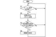
図2に、管理システム101の動作例の一部を示す。図3に、管理システム101による、携帯ビーコン端末1の位置情報の管理に関する動作例を示す。図4に、入退管理器5の動作例を示す。図5に、携帯ビーコン端末1の動作例を示す。なお、図2~図5は、動作の一例を示しているに過ぎず、処理の順序が適宜変更されてもよいし、処理が適宜追加又は省略されてもよい。 (6) Operation Example Fig. 2 shows a part of an operation example of the
管理制御部20は、管理端末11の管理側NFCアンテナ16aの制御モードとして、送信モードと、受信モードと、を有する(図2のS1、S2)。管理側NFCアンテナ16aは、例えば、パネルにより覆われている。携帯ビーコン端末1がパネルに接触、又は近接することで、携帯ビーコン端末1が管理側NFCアンテナ16aに近接する。The
まず、送信モードでは、管理側NFCアンテナ16aから高周波信号(磁界M1)がNFC(近距離無線通信)方式により出力される。このとき、管理端末11の管理側NFCアンテナ16aに近接した携帯ビーコン端末1が存在すると、管理側NFCアンテナ16aから出力された高周波信号が、携帯ビーコン端末1の入退管理器5のNFCアンテナ8で受信される(図4のS1:Yes)。入退管理器5は、RFID等と同様に、高周波信号から得られる電力を整流する。この電力により、入退管理制御部9が起動する。次に、入退管理器5の第2メモリ10に格納された管理ID(入退管理情報)を含む信号が、NFCアンテナ8から管理端末11の管理側NFCアンテナ16aへと出力される(図4のS2)。管理端末11では、管理側NFCアンテナ16aの制御モードは受信モード(図2のS2)になっているので、入退管理器5の第2メモリ10に格納された管理IDが、管理端末11の管理側NFCアンテナ16aによって受信される(図2のS3:Yes)。First, in the transmission mode, a high-frequency signal (magnetic field M1) is output from the management
管理装置15のメモリ23には、ユーザの認証に用いる情報が記憶されている。具体的には、メモリ23には、ユーザの認証に用いる情報として、複数の管理IDが記憶されている。さらに、メモリ23には、ユーザの認証に用いる情報として、各管理IDと、各管理端末11に対応したエリアへの入域許可又は不許可と、を紐付ける情報が記憶されている。例えば、ある1つの管理IDは、複数の管理端末11のうち一部の管理端末11に対応したエリアへの入域許可と紐付けられており、その他の管理端末11に対応したエリアへの入域不許可と紐付けられている。The
管理端末11(の管理側NFCアンテナ16a)によって管理IDが受信されると、管理端末11は、受信した管理IDと、自機(管理端末11)のIDと、を管理装置15に送信する。管理装置15の管理制御部20は、メモリ23に記憶された情報を参照する。これにより、管理制御部20は、管理端末11によって受信された管理IDが、その管理端末11に対応したエリアへの入域許可と紐付けられているか、否かの判定を行う(図2のS4)。When the management ID is received by the management terminal 11 (the management
管理端末11によって受信された管理IDが、その管理端末11に対応したエリアへの入域許可と紐付けられている場合(図2のS4:Yes)は、管理制御部20は、入域許可処理として、管理端末11の認証出力部19の、発光色が緑色の表示灯を点灯させたり、管理端末11と対応したゲート26を解錠したりする(図2のS5)。また、この場合、管理IDがメモリ23に記憶されているため、管理IDを用いてのユーザ(携帯ビーコン端末1)の認証結果は、「認証成功」かつ「入域許可」である。If the management ID received by the
管理端末11によって受信された管理IDが、その管理端末11に対応したエリアへの入域許可と紐付けられていない場合(図2のS4:No)は、管理制御部20は、入域不許可処理として、管理端末11の認証出力部19の、発光色が赤色の表示灯を点灯させる(図2のS6)。また、この場合は、管理制御部20は、管理端末11と対応したゲート26を施錠した状態を維持する。ここで、管理IDがメモリ23に記憶されている場合は、認証結果は、「認証成功」かつ「入域不許可」である(図2のS7:Yes)。管理IDがメモリ23に記憶されていない場合は、認証結果は、「認証失敗」かつ「入域不許可」である(図2のS7:No)。If the management ID received by the
認証結果が「認証成功」を含む場合は、次に、管理制御部20は、充電要請の有無を判定する(図2のS8)。すなわち、管理制御部20は、受信モード(図2のS2)において受信された信号に、蓄電池4の充電要請が含まれているか、否かの判定を行う。充電要請があった場合(図2のS8:Yes)は、報知部18は、例えば音声によって、蓄電池4の残容量が閾値よりも小さくなったことを、携帯ビーコン端末1を所持するユーザに伝える(図2のS9)。このときは、携帯ビーコン端末1を所持するユーザが、携帯ビーコン端末1を管理端末11に近接、又は接触させている状況である。そのため、ユーザは、管理端末11の認証出力部19で入域許可を表す表示がされたこと、及び、その後に、報知部18から音声で、蓄電池4の残容量が閾値よりも小さくなったことが報知されたことに、容易に気付くことができる。つまり、ユーザが、入域許可がされるか否かに注意を払っている状況であるので、ユーザは、蓄電池4の残容量が閾値よりも小さくなったことについての、音声による報知を注意深く聞き取り、認識できる。If the authentication result includes "authentication success", the
このようにして管理端末11に、蓄電池4の充電要請が届くと、管理制御部20は、充電コイル17への通電を始める(図2のS10)。充電コイル17への通電が始まると、管理端末11に近接、又は接触した携帯ビーコン端末1のコイル12に磁界M2が印加され、これにより、電磁充電部6を介して蓄電池4への充電が行われる。When a request to charge the
管理装置15は、充電コイル17への通電開始後も携帯ビーコン端末1と管理端末11との間で通信が続いているか、否かを確認している。携帯ビーコン端末1が管理端末11に近接、又は接触している状態が継続していると、管理制御部20は、充電コイル17への通電を継続し、蓄電池4の充電を継続する。しかしながら、管理端末11には、多くの人が、次々に認証のために携帯ビーコン端末1を管理端末11に近づける作業を行ってくる場合がある。また、蓄電池4の残容量が閾値よりも小さくなったことを報知されたユーザが、急ぎの用で、そこに立ち止まることができないこともある。これらのような場合には、管理端末11から携帯ビーコン端末1が離れるので、管理制御部20は、携帯ビーコン端末1から送信される、管理IDを含む信号を受信することができず、充電コイル17への通電を停止することになる(図2のS3:No、図2のS11)。The
また、管理IDが管理システム101に登録されておらず、認証結果が「認証失敗」を含む場合にも、管理制御部20は、充電コイル17への通電を停止することになる(図2のS7:No、図2のS11)。In addition, if the management ID is not registered in the
実際の運用としては、蓄電池4の残容量が閾値よりも小さくなったことを報知部18によって知らされたユーザは、時間が有るとき、かつ、他のユーザが管理端末11に携帯ビーコン端末1をかざす作業をしていない状況で、長時間(例えば、10秒程度)、携帯ビーコン端末1を管理端末11に近接、又は接触させることで、蓄電池4への充電を行うことになる。In actual operation, when a user is notified by the
また、認証のためにユーザが管理端末11へアクセスする機会が多い場合は、蓄電池4を充電する回数も多くなるので、蓄電池4の残容量が閾値よりも小さくなる事態が起きにくい。In addition, if a user frequently accesses the
また、蓄電池4への充電が行われて、蓄電池4の残容量が閾値以上になると、報知部18は、報知をしなくなるので、ユーザは、蓄電池4への充電が十分に行われたことを認識することができる。In addition, when the
ここで、携帯ビーコン端末1は、残容量が第1閾値より小さいときに、充電要請を含む信号を管理端末11へ送信し、残容量が第2閾値以上のときに、充電停止要請を含む信号を管理端末11へ送信してもよい。第2閾値は第1閾値よりも大きい。管理端末11が充電停止要請を含む信号を受信すると、管理制御部20は、充電コイル17への通電を停止する。Here, the portable beacon terminal 1 may transmit a signal including a charging request to the
次に、携帯ビーコン端末1の動作についての説明を続ける。Next, we will continue to explain the operation of the portable beacon terminal 1.
図4に示すように、入退管理器5の入退管理制御部9は、入退管理器5の第2メモリ10に格納された管理IDを、NFCアンテナ8から管理端末11の管理側NFCアンテナ16aへと出力した(図4のS2)のちに、ビーコン制御部3に対して、管理IDを管理端末11の管理側NFCアンテナ16aへと出力したことを伝える(図4のS3)。As shown in FIG. 4, the entrance/exit
ビーコン制御部3は、第1メモリ25に格納されたビーコンIDを含むビーコン信号B1を、ビーコン送信部2から断続的に出力している(図5のS1)。ビーコン信号B1は、複数のビーコン受信部21によって受信され(図3のS1)、複数のビーコン受信部21は、ビーコン信号B1の受信信号強度の情報を管理装置15に送信する。管理装置15の管理制御部20は、受信信号強度の情報に基づいて、携帯ビーコン端末1の位置を求め、メモリ23に更新登録する(図3のS2)。The
管理者が入力IF24に対して、特定個人の居場所を特定するための操作をすると(図3のS3:Yes)、出力IF22に、居場所が表示される(図3のS4)。When the administrator operates the input IF 24 to identify the location of a specific individual (S3 in FIG. 3: Yes), the location is displayed on the output IF 22 (S4 in FIG. 3).
図5に戻り、携帯ビーコン端末1の動作を説明する。Returning to Figure 5, the operation of the portable beacon terminal 1 will now be described.
携帯ビーコン端末1のビーコン制御部3は、上述したように第1メモリ25に格納されたビーコンIDを含むビーコン信号B1を、ビーコン送信部2から断続的に出力している(図5のS1)。ビーコン制御部3は、ビーコン信号B1を、ビーコン送信部2から出力したのちに、毎回、あるいは定期的に、残容量検出部7によって蓄電池4の電圧を検出し、検出した電圧の値が所定値よりも低いか、否かの判定を行い、判定結果を第1メモリ25に更新登録している(図5のS2、S3)。検出した電圧の値が所定値よりも低いときは、ビーコン制御部3は、残容量が低下している(残容量が閾値よりも小さい)と判断する。The
上述のように、入退管理器5の第2メモリ10に格納された管理IDが、NFCアンテナ8から管理端末11の管理側NFCアンテナ16aへと出力された(図4のS2)のちに、入退管理制御部9は、管理IDを管理端末11の管理側NFCアンテナ16aへと出力したことを、ビーコン制御部3に伝える(図4のS3)。As described above, after the management ID stored in the
ビーコン制御部3側からみると、管理IDを管理端末11の管理側NFCアンテナ16aへと出力したことが伝えられる(図5のS5)。このときは、携帯ビーコン端末1が管理端末11に近接、又は接触している状態で、NFCアンテナ8から信号を、NFC方式により管理端末11に出力することができる状態である。したがって、第1メモリ25に、蓄電池4の電圧が所定値よりも低いという情報が存在するときには(図5のS4:Yes)、ビーコン制御部3は、NFCアンテナ8を介して管理端末11に充電要請を伝える(図5のS6)。From the
(7)実施形態の小括
以上のように、本実施形態の携帯ビーコン端末1は、ビーコン送信部2と、ビーコン送信部2に接続されたビーコン制御部3と、ビーコン制御部3及びビーコン送信部2に電源電力を供給する蓄電池4と、蓄電池4からの電源電力の供給を受けずに入退管理情報をNFC方式により出力する入退管理器5と、を備えている。蓄電池4には、電磁充電部6と、残容量検出部7とが接続される。ビーコン制御部3は、入退管理器5のNFCアンテナ8を介して、蓄電池4への充電要請を含む信号を管理端末11へ出力する。 (7) Summary of the embodiment As described above, the portable beacon terminal 1 of the present embodiment includes a
このような構成により、ユーザの入退管理及び居場所特定に対する信頼性を高めることができ、しかも、設置コストを抑制できる。This configuration can improve the reliability of user entry/exit management and location identification, while also reducing installation costs.
すなわち、携帯ビーコン端末1を管理端末11に接触、又は近接させると、入退管理器5から入退管理情報がNFC方式により出力され、入退管理が行える。また、ビーコン送信部2から送信されるビーコン信号B1により、ユーザの入退管理及び居場所管理が行える。In other words, when the portable beacon terminal 1 is brought into contact with or close proximity to the
さらに、残容量検出部7で、蓄電池4の残容量が閾値よりも小さくなったことが検出されたときには、携帯ビーコン端末1は、入退管理器5のNFCアンテナ8を介し、蓄電池4への充電要請を含む信号を管理端末11に出力する。すると、管理端末11から供給される充電用磁束(磁界M2)により、電磁充電部6を介して蓄電池4が充電される。より詳細には、携帯ビーコン端末1の入退管理制御部9は、残容量検出部7で検出された蓄電池4の残容量が閾値よりも小さくなったときであって、入退管理制御部9が管理ID(入退管理情報)を含む信号を管理端末11へ、NFCアンテナ8を介した近距離無線通信により送信するときに、蓄電池4の充電要請を含む信号を管理端末11へ、NFCアンテナ8を介した近距離無線通信により送信する。つまり、本実施形態では、ユーザの認証のために管理端末11に携帯ビーコン端末1を接触、又は近接させるときに、蓄電池4の充電が行えるので、充電の手間を別途設ける必要がなく、携帯ビーコン端末1の使い勝手が良くなる。また、このような特定のエリアへの入域時に蓄電池4への充電を行うので、充電の機会が多く、電池切れを起こすことが少なくなる。よって、入退管理及び居場所特定に対する信頼性が高くなる。Furthermore, when the remaining
さらに、管理端末11は、充電コイル17を備えており、蓄電池4を充電するための充電装置として使用される。充電装置を施設の広い範囲に多数設置すると、設置コストが高くなり、好ましくない。また、充電のために使用される機会が少ない充電装置が存在すると、その充電装置を設置した意義が薄く、好ましくない。そこで、本実施形態では、入退管理で用いられる管理端末11を、充電装置として兼用しているので、設置コストを抑制できる。しかも、管理端末11はユーザの入退管理のために使用される機器であるから、ユーザはある程度の頻度で、管理端末11が設置された場所に立ち入ることになる。よって、管理端末11(充電装置)が充電のために使用される機会を確保することができる。Furthermore, the
(実施形態の変形例)
以下、実施形態の変形例を列挙する。以下の変形例は、適宜組み合わせて実現されてもよい。なお、以下では、上述した実施形態の構成を、基本例と呼ぶ。 (Modification of the embodiment)
Modifications of the embodiment are listed below. The following modifications may be implemented in appropriate combination. Note that, hereinafter, the configuration of the embodiment described above will be referred to as a basic example.
蓄電池4は、携帯ビーコン端末1の構成要素に含まれていなくてもよい。The
携帯ビーコン端末1は、ICカードに限定されない。携帯ビーコン端末1は、例えば、スマートフォン等の携帯電話、又は、ウェアラブル端末等であってもよい。The portable beacon terminal 1 is not limited to an IC card. The portable beacon terminal 1 may be, for example, a mobile phone such as a smartphone, or a wearable terminal.
管理システム101がユ―ザの認証結果に基づいて、特定のエリアの出入り口に設置されたゲート26を施錠又は解錠することは、必須ではない。例えば、管理システム101の認証結果に関わらず、特定のエリアに対してユーザが自由に入域及び退域可能であって、管理システム101は、ユーザの認証結果をメモリ23に記憶してもよい。あるいは、管理システム101がユ―ザの認証結果に基づいて、特定のエリアの出入り口に設置されたゲート26を、出入り口を塞ぐ位置と出入り口を開放する位置との間で移動させてもよい。It is not necessary for the
残容量検出部7は、蓄電池4の充放電電流を検出してもよい。ビーコン制御部3は、充放電電流の積算値から、蓄電池4の残容量を求めることができる。The remaining
報知部18は、蓄電池4の残容量が閾値よりも小さくなったことを、視覚的に報知してもよい。報知部18は、例えば、表示灯を含み、表示灯を点灯させることにより、残容量が閾値よりも小さくなったことを報知してもよい。あるいは、報知部18は、例えば、ディスプレイを含み、ディスプレイに所定の文字又は記号等を表示させることにより、残容量が閾値よりも小さくなったことを報知してもよい。The
認証出力部19は、認証結果を、音(例えば、音声)により報知してもよい。The
基本例では、認証結果が「認証成功」を含んでいれば、認証結果が「入域不許可」を含んでいても、管理制御部20は、充電要請に応じて、充電コイル17への通電を開始する。これに対して、管理制御部20は、認証結果が「認証成功」及び「入域許可」の両方を含んでいる場合にのみ、充電要請に応じて、充電コイル17への通電を開始してもよい。In the basic example, if the authentication result includes "authentication successful", the
基本例では、入退管理制御部9は、管理IDを含む信号を管理端末11へ送信した後に、蓄電池4の充電要請を含む信号を管理端末11へ送信する。これに対して、入退管理制御部9は、管理IDと充電要請との両方を含む信号を管理端末11へ送信してもよいし、充電要請を含む信号を管理端末11へ送信した後に、管理IDを含む信号を管理端末11へ送信してもよい。In the basic example, the entry/exit
管理制御部20は、ビーコン信号B1の受信信号強度に代えて、例えば、ビーコン信号B1の位相に基づいて、携帯ビーコン端末1の位置情報を求めてもよい。The
1つの携帯ビーコン端末1において、当該携帯ビーコン端末1の管理IDとビーコンIDとが、一致していてもよい。For one mobile beacon terminal 1, the management ID and beacon ID of that mobile beacon terminal 1 may be the same.
本開示における携帯ビーコン端末1及び管理システム101は、コンピュータシステムを含んでいる。コンピュータシステムは、ハードウェアとしてのプロセッサ及びメモリを主構成とする。コンピュータシステムのメモリに記録されたプログラムをプロセッサが実行することによって、本開示における携帯ビーコン端末1及び管理システム101としての機能の少なくとも一部が実現される。プログラムは、コンピュータシステムのメモリに予め記録されてもよく、電気通信回線を通じて提供されてもよく、コンピュータシステムで読み取り可能なメモリカード、光学ディスク、ハードディスクドライブ等の非一時的記録媒体に記録されて提供されてもよい。コンピュータシステムのプロセッサは、半導体集積回路(IC)又は大規模集積回路(LSI)を含む1ないし複数の電子回路で構成される。ここでいうIC又はLSI等の集積回路は、集積の度合いによって呼び方が異なっており、システムLSI、VLSI(Very Large Scale Integration)、又はULSI(Ultra Large Scale Integration)と呼ばれる集積回路を含む。さらに、LSIの製造後にプログラムされる、FPGA(Field-Programmable Gate Array)、又はLSI内部の接合関係の再構成若しくはLSI内部の回路区画の再構成が可能な論理デバイスについても、プロセッサとして採用することができる。複数の電子回路は、1つのチップに集約されていてもよいし、複数のチップに分散して設けられていてもよい。複数のチップは、1つの装置に集約されていてもよいし、複数の装置に分散して設けられていてもよい。ここでいうコンピュータシステムは、1以上のプロセッサ及び1以上のメモリを有するマイクロコントローラを含む。したがって、マイクロコントローラについても、半導体集積回路又は大規模集積回路を含む1ないし複数の電子回路で構成される。The mobile beacon terminal 1 and the
また、実施形態において、1つの筐体に集約されている複数の機能が、複数の筐体に分散して設けられていてもよい。例えば、管理装置15の複数の機能が、複数の筐体に分散して設けられていてもよい。In addition, in the embodiment, multiple functions that are concentrated in one housing may be distributed across multiple housings. For example, multiple functions of the
反対に、実施形態において、複数の筐体に分散されている複数の機能が、1つの筐体に集約されていてもよい。例えば、複数の管理端末11のうち少なくとも1つの管理端末11が、ビーコン受信部21を備えていてもよい。また、管理端末11は、管理制御部20の少なくとも一部の機能を有していてもよい。管理端末11の個数が1つの場合、管理端末11と管理装置15とが1つの筐体に集約されていてもよい。Conversely, in an embodiment, multiple functions that are distributed across multiple housings may be consolidated into one housing. For example, at least one of the
(まとめ)
以上説明した実施形態等から、以下の態様が開示されている。 (summary)
The above-described embodiments and the like disclose the following aspects.
第1の態様に係る携帯ビーコン端末(1)は、ビーコン送信部(2)と、ビーコン制御部(3)と、導電部材(4a、4b)と、入退管理器(5)と、電磁充電部(6)と、残容量検出部(7)と、を備える。ビーコン送信部(2)は、ビーコン信号(B1)を送信する。ビーコン制御部(3)は、ビーコン送信部(2)を制御する。導電部材(4a、4b)は、蓄電池(4)に電気的に接続される。蓄電池(4)は、ビーコン送信部(2)及びビーコン制御部(3)に電源電力を供給する。入退管理器(5)は、NFCアンテナ(8)と、入退管理制御部(9)と、を有する。NFCアンテナ(8)は、管理端末(11)から磁界(M1)が印加されたときに誘導起電力を発生する。入退管理制御部(9)は、NFCアンテナ(8)で発生する誘導起電力を電源電力として用いて、入退管理に関する入退管理情報を含む信号を管理端末(11)へ、NFCアンテナ(8)を介した近距離無線通信により送信する。電磁充電部(6)は、管理端末(11)から印加される磁界(M2)を用いた電磁誘導方式のワイヤレス給電により、蓄電池(4)を充電する。残容量検出部(7)は、蓄電池(4)の残容量を検出する。入退管理制御部(9)は、残容量検出部(7)で検出された残容量が閾値よりも小さくなったときに、蓄電池(4)の充電要請を含む信号を管理端末(11)へ、NFCアンテナ(8)を介した近距離無線通信により送信する。The portable beacon terminal (1) according to the first aspect includes a beacon transmitter (2), a beacon control unit (3), conductive members (4a, 4b), an entrance/exit management device (5), an electromagnetic charging unit (6), and a remaining capacity detection unit (7). The beacon transmitter (2) transmits a beacon signal (B1). The beacon control unit (3) controls the beacon transmitter (2). The conductive members (4a, 4b) are electrically connected to a storage battery (4). The storage battery (4) supplies power to the beacon transmitter (2) and the beacon control unit (3). The entrance/exit management device (5) includes an NFC antenna (8) and an entrance/exit management control unit (9). The NFC antenna (8) generates an induced electromotive force when a magnetic field (M1) is applied from the management terminal (11). The entrance/exit management control unit (9) uses the induced electromotive force generated by the NFC antenna (8) as power source power to transmit a signal including entrance/exit management information related to entrance/exit management to the management terminal (11) by short-range wireless communication via the NFC antenna (8). The electromagnetic charging unit (6) charges the storage battery (4) by wireless power supply using an electromagnetic induction method that uses a magnetic field (M2) applied from the management terminal (11). The remaining capacity detection unit (7) detects the remaining capacity of the storage battery (4). When the remaining capacity detected by the remaining capacity detection unit (7) becomes smaller than a threshold value, the entrance/exit management control unit (9) transmits a signal including a request to charge the storage battery (4) to the management terminal (11) by short-range wireless communication via the NFC antenna (8).
上記の構成によれば、ユーザは、携帯ビーコン端末(1)を所持して管理端末(11)に近付いたときに、蓄電池(4)を充電することができる。しかも、管理端末(11)は、入退管理情報を含む信号の送信先であるから、ユーザはある程度の頻度で、管理端末(11)が設置された場所に立ち入ることになる。つまり、蓄電池(4)を充電する機会が、ある程度の頻度で確保される。よって、蓄電池(4)の残容量の低下によって携帯ビーコン端末(1)がビーコン信号(B1)を送信することができなくなる可能性を低減できる。According to the above configuration, when a user carries a portable beacon terminal (1) and approaches the management terminal (11), the user can charge the storage battery (4). Moreover, since the management terminal (11) is the destination of a signal including entry/exit management information, the user will enter the location where the management terminal (11) is installed with a certain degree of frequency. In other words, the opportunity to charge the storage battery (4) is ensured with a certain degree of frequency. This reduces the possibility that the portable beacon terminal (1) will be unable to transmit a beacon signal (B1) due to a decrease in the remaining capacity of the storage battery (4).
また、第2の態様に係る携帯ビーコン端末(1)では、第1の態様において、入退管理制御部(9)は、残容量検出部(7)で検出された残容量が閾値よりも小さくなったときであって、入退管理制御部(9)が入退管理情報を含む信号を管理端末(11)へ、NFCアンテナ(8)を介した近距離無線通信により送信するときに、蓄電池(4)の充電要請を含む信号を管理端末(11)へ、NFCアンテナ(8)を介した近距離無線通信により送信する。In addition, in the portable beacon terminal (1) according to the second aspect, in the first aspect, when the remaining capacity detected by the remaining capacity detection unit (7) becomes smaller than the threshold value and the entrance/exit management control unit (9) transmits a signal including the entrance/exit management information to the management terminal (11) by short-range wireless communication via the NFC antenna (8), the entrance/exit management control unit (9) transmits a signal including a request to charge the storage battery (4) to the management terminal (11) by short-range wireless communication via the NFC antenna (8).
上記の構成によれば、携帯ビーコン端末(1)が入退管理情報を含む信号を管理端末(11)へ送信するとき、携帯ビーコン端末(1)は、蓄電池(4)の充電要請を含む信号を管理端末(11)に送信する。つまり、携帯ビーコン端末(1)は、入退管理情報の送信と、充電要請と、をまとめて行う。よって、ユーザにとっての利便性が向上する。According to the above configuration, when the portable beacon terminal (1) transmits a signal including the entrance/exit management information to the management terminal (11), the portable beacon terminal (1) transmits a signal including a request to charge the storage battery (4) to the management terminal (11). In other words, the portable beacon terminal (1) transmits the entrance/exit management information and the request to charge all at once. This improves convenience for the user.
第1の態様以外の構成については、携帯ビーコン端末(1)に必須の構成ではなく、適宜省略可能である。Configurations other than the first aspect are not essential for the portable beacon terminal (1) and may be omitted as appropriate.
また、第3の態様に係る入退管理システム(100)は、第1又は2の態様に係る携帯ビーコン端末(1)と、管理システム(101)と、を備える。管理システム(101)は、管理端末(11)を含む。管理端末(11)は、通信器(16)と、充電コイル(17)と、報知部(18)と、を有する。通信器(16)は、管理側NFCアンテナ(16a)を含む。通信器(16)は、携帯ビーコン端末(1)の入退管理器(5)と近距離無線通信をする。充電コイル(17)は、携帯ビーコン端末(1)の電磁充電部(6)に対して、蓄電池(4)を充電するための磁界(M2)を印加する。報知部(18)は、携帯ビーコン端末(1)の蓄電池(4)の残容量が閾値よりも小さくなったことをユーザに報知する。管理システム(101)は、管理端末(11)の通信器(16)が携帯ビーコン端末(1)から、蓄電池(4)の充電要請を含む信号を受信した場合に、報知部(18)に所定の報知をさせる。The entrance/exit management system (100) according to the third aspect includes the mobile beacon terminal (1) according to the first or second aspect and a management system (101). The management system (101) includes a management terminal (11). The management terminal (11) has a communicator (16), a charging coil (17), and an alarm unit (18). The communicator (16) includes a management side NFC antenna (16a). The communicator (16) performs short-range wireless communication with the entrance/exit management device (5) of the mobile beacon terminal (1). The charging coil (17) applies a magnetic field (M2) to the electromagnetic charging unit (6) of the mobile beacon terminal (1) for charging the storage battery (4). The alarm unit (18) notifies the user that the remaining capacity of the storage battery (4) of the mobile beacon terminal (1) has become smaller than a threshold value. When the communication device (16) of the management terminal (11) receives a signal including a request to charge the storage battery (4) from the portable beacon terminal (1), the management system (101) causes the notification unit (18) to issue a predetermined notification.
上記の構成によれば、ユーザは、携帯ビーコン端末(1)を管理端末(11)に近接、又は接触させて、所定の報知があったときに、蓄電池(4)の残容量の低下を知ることができる。よって、ユーザは、充電が完了するまで待機する等の行動を取ることができる。According to the above configuration, the user can know the remaining capacity of the storage battery (4) is decreasing when a predetermined notification is received by bringing the portable beacon terminal (1) close to or in contact with the management terminal (11). Therefore, the user can take action such as waiting until charging is completed.
また、第4の態様に係る入退管理システム(100)では、第3の態様において、管理システム(101)は、携帯ビーコン端末(1)からビーコン信号(B1)を受信するビーコン受信部(21)から、ビーコン信号(B1)の受信に関する情報を含む信号を取得する。管理システム(101)は、ビーコン信号(B1)の受信に関する情報に基づいて、携帯ビーコン端末(1)の位置情報を求める。In addition, in the entrance/exit management system (100) according to the fourth aspect, in the third aspect, the management system (101) acquires a signal including information regarding the reception of the beacon signal (B1) from the beacon receiving unit (21) that receives the beacon signal (B1) from the portable beacon terminal (1). The management system (101) obtains location information of the portable beacon terminal (1) based on the information regarding the reception of the beacon signal (B1).
上記の構成によれば、管理システム(101)は、携帯ビーコン端末(1)の位置情報(すなわち、携帯ビーコン端末(1)を所持するユーザの位置情報)を求めることができる。According to the above configuration, the management system (101) can obtain location information of the mobile beacon terminal (1) (i.e., location information of the user who possesses the mobile beacon terminal (1)).
また、第5の態様に係る入退管理システム(100)では、第3又は4の態様において、管理システム(101)は、携帯ビーコン端末(1)から管理端末(11)が取得した入退管理情報を用いてのユーザの認証に成功してから、充電コイル(17)に、蓄電池(4)を充電するための磁界(M2)を発生させる。In addition, in the entry/exit management system (100) according to the fifth aspect, in the third or fourth aspect, the management system (101) causes the charging coil (17) to generate a magnetic field (M2) for charging the storage battery (4) after successfully authenticating the user using the entry/exit management information acquired by the management terminal (11) from the portable beacon terminal (1).
上記の構成によれば、正当なユーザが所持する携帯ビーコン端末(1)が管理端末(11)に近づいたときにのみ、充電コイル(17)は、蓄電池(4)を充電するための磁界(M2)を発生する。そのため、電力消費を低減できる。According to the above configuration, the charging coil (17) generates a magnetic field (M2) for charging the storage battery (4) only when the portable beacon terminal (1) carried by a legitimate user approaches the management terminal (11). This reduces power consumption.
また、第6の態様に係る入退管理システム(100)では、第3~5の態様のいずれか1つにおいて、管理システム(101)は、管理端末(11)を複数備える。管理システム(101)は、複数の管理端末(11)と通信する管理装置(15)を更に備える。管理装置(15)は、ユーザの認証に用いる情報を記憶するメモリ(23)を有する。In addition, in the entrance/exit management system (100) according to the sixth aspect, in any one of the third to fifth aspects, the management system (101) includes a plurality of management terminals (11). The management system (101) further includes a management device (15) that communicates with the plurality of management terminals (11). The management device (15) has a memory (23) that stores information used for authenticating a user.
上記の構成によれば、ユーザの認証に関する情報を管理装置(15)にて集中管理することができる。According to the above configuration, information regarding user authentication can be centrally managed by the management device (15).
第3の態様以外の構成については、入退管理システム(100)に必須の構成ではなく、適宜省略可能である。Configurations other than the third aspect are not essential for the entrance/exit management system (100) and may be omitted as appropriate.
1 携帯ビーコン端末
2 ビーコン送信部
3 ビーコン制御部
4 蓄電池
4a、4b 導電部材
5 入退管理器
6 電磁充電部
7 残容量検出部
8 NFCアンテナ
9 入退管理制御部
11 管理端末
15 管理装置
16 通信器
16a 管理側NFCアンテナ
17 充電コイル
18 報知部
21 ビーコン受信部
23 メモリ
100 入退管理システム
101 管理システム
B1 ビーコン信号
M1、M2 磁界1
Claims (6)
Translated fromJapanese前記ビーコン送信部を制御するビーコン制御部と、
前記ビーコン送信部及び前記ビーコン制御部に電源電力を供給する蓄電池に電気的に接続される導電部材と、
管理端末から磁界が印加されたときに誘導起電力を発生するNFCアンテナと、前記NFCアンテナで発生する前記誘導起電力を電源電力として用いて、入退管理に関する入退管理情報を含む信号を前記管理端末へ、前記NFCアンテナを介した近距離無線通信により送信する入退管理制御部と、を有する、入退管理器と、
前記管理端末から印加される磁界を用いた電磁誘導方式のワイヤレス給電により、前記蓄電池を充電する電磁充電部と、
前記蓄電池の残容量を検出する残容量検出部と、を備え、
前記入退管理制御部は、前記残容量検出部で検出された前記残容量が閾値よりも小さくなったときに、前記蓄電池の充電要請を含む信号を前記管理端末へ、前記NFCアンテナを介した近距離無線通信により送信する、
携帯ビーコン端末。 a beacon transmitter for transmitting a beacon signal;
a beacon control unit that controls the beacon transmission unit;
a conductive member electrically connected to a storage battery that supplies power to the beacon transmitter and the beacon controller;
an entrance/exit management device having an NFC antenna that generates an induced electromotive force when a magnetic field is applied from a management terminal, and an entrance/exit management control unit that uses the induced electromotive force generated in the NFC antenna as a power source power to transmit a signal including entrance/exit management information related to entrance/exit management to the management terminal by short-range wireless communication via the NFC antenna;
an electromagnetic charging unit that charges the storage battery by wireless power supply using an electromagnetic induction method that uses a magnetic field applied from the management terminal;
a remaining capacity detection unit that detects a remaining capacity of the storage battery,
When the remaining capacity detected by the remaining capacity detection unit becomes smaller than a threshold value, the entry/exit management control unit transmits a signal including a request to charge the storage battery to the management terminal by short-range wireless communication via the NFC antenna.
Mobile beacon device.
請求項1に記載の携帯ビーコン端末。 when the remaining capacity detected by the remaining capacity detection unit becomes smaller than a threshold value and the entrance/exit management control unit transmits a signal including the entrance/exit management information to the management terminal by short-range wireless communication via the NFC antenna, the entrance/exit management control unit transmits a signal including the charging request for the storage battery to the management terminal by short-range wireless communication via the NFC antenna.
2. The portable beacon terminal according to claim 1.
前記管理端末を含む管理システムと、を備え、
前記管理端末は、
管理側NFCアンテナを含み、前記携帯ビーコン端末の前記入退管理器と近距離無線通信をする通信器と、
前記携帯ビーコン端末の前記電磁充電部に対して、前記蓄電池を充電するための磁界を印加する充電コイルと、
前記携帯ビーコン端末の前記蓄電池の前記残容量が閾値よりも小さくなったことをユーザに報知する報知部と、を有し、
前記管理システムは、前記管理端末の前記通信器が前記携帯ビーコン端末から、前記蓄電池の前記充電要請を含む信号を受信した場合に、前記報知部に所定の報知をさせる、
入退管理システム。 A mobile beacon terminal according to claim 1 or 2,
a management system including the management terminal;
The management terminal includes:
A communication device including a management side NFC antenna and performing short-range wireless communication with the front-end management device of the mobile beacon terminal;
A charging coil that applies a magnetic field to the electromagnetic charging unit of the portable beacon terminal in order to charge the storage battery;
a notification unit that notifies a user that the remaining capacity of the storage battery of the portable beacon terminal has become smaller than a threshold value,
When the communication device of the management terminal receives a signal including a request to charge the storage battery from the portable beacon terminal, the management system causes the notification unit to issue a predetermined notification.
Entrance/exit control system.
前記携帯ビーコン端末から前記ビーコン信号を受信するビーコン受信部から、前記ビーコン信号の受信に関する情報を含む信号を取得し、
前記ビーコン信号の受信に関する情報に基づいて、前記携帯ビーコン端末の位置情報を求める、
請求項3に記載の入退管理システム。 The management system includes:
A signal including information regarding reception of the beacon signal is obtained from a beacon receiving unit that receives the beacon signal from the portable beacon terminal;
determining location information of the mobile beacon terminal based on information regarding reception of the beacon signal;
The entrance/exit management system according to claim 3.
請求項3に記載の入退管理システム。 The management system causes the charging coil to generate the magnetic field for charging the storage battery after the user authentication is successful using the entrance/exit management information acquired by the management terminal from the mobile beacon terminal.
The entrance/exit management system according to claim 3.
前記管理端末を複数備え、
前記複数の管理端末と通信する管理装置を更に備え、
前記管理装置は、ユーザの認証に用いる情報を記憶するメモリを有する、
請求項3に記載の入退管理システム。 The management system includes:
A plurality of the management terminals are provided,
A management device that communicates with the plurality of management terminals,
The management device has a memory for storing information used for authenticating a user.
The entrance/exit management system according to claim 3.
Priority Applications (1)
| Application Number | Priority Date | Filing Date | Title |
|---|---|---|---|
| JP2023052217AJP2024140866A (en) | 2023-03-28 | 2023-03-28 | Mobile beacon terminal and entrance/exit management system |
Applications Claiming Priority (1)
| Application Number | Priority Date | Filing Date | Title |
|---|---|---|---|
| JP2023052217AJP2024140866A (en) | 2023-03-28 | 2023-03-28 | Mobile beacon terminal and entrance/exit management system |
Publications (1)
| Publication Number | Publication Date |
|---|---|
| JP2024140866Atrue JP2024140866A (en) | 2024-10-10 |
Family
ID=92974917
Family Applications (1)
| Application Number | Title | Priority Date | Filing Date |
|---|---|---|---|
| JP2023052217APendingJP2024140866A (en) | 2023-03-28 | 2023-03-28 | Mobile beacon terminal and entrance/exit management system |
Country Status (1)
| Country | Link |
|---|---|
| JP (1) | JP2024140866A (en) |
- 2023
- 2023-03-28JPJP2023052217Apatent/JP2024140866A/enactivePending
Similar Documents
| Publication | Publication Date | Title |
|---|---|---|
| CN108353361B (en) | Electronic equipment, related mobile equipment and control method thereof | |
| US9502909B2 (en) | Power management for electronic devices | |
| JP5752056B2 (en) | Wireless power transfer for rechargeable devices | |
| US9716402B2 (en) | Systems and methods for wireless power and data transfer for electronic devices | |
| CN104995815B (en) | Wireless power transmitter and receiver, and pass through the method for wireless power transmitter unlicensed radio power receiver | |
| EP3047557B1 (en) | Low power detection of wireless power devices | |
| EP2428912B1 (en) | System and method for responding to a request received at an object with an RFID device | |
| WO2014103191A1 (en) | Power supply apparatus, control method, program, and storage medium | |
| KR20110115602A (en) | Wireless Power Supply and Wireless Communication for Electronic Devices | |
| CN108695997A (en) | Transmission facility and its control method and storage medium | |
| KR20130135260A (en) | Wireless charging of devices | |
| JP2013084243A (en) | Selection method of near-field communication and wireless charging shared sensor module, and selection circuit therefor | |
| CN110037391A (en) | A kind of key chain | |
| KR20170142085A (en) | Wireless power transmitter, wireless power receiver and method for controlling thereof | |
| JP4816609B2 (en) | Location management system and reader and terminal used therefor | |
| JP2024140866A (en) | Mobile beacon terminal and entrance/exit management system | |
| JPWO2020066202A1 (en) | Entry management system, entry management method, portable device, entry notification method, and program | |
| CN117880747B (en) | Control method, equipment and storage medium of hotel system | |
| JP5785013B2 (en) | Lock system | |
| CN113439377A (en) | Improved system and method for wireless charging | |
| WO2020191780A1 (en) | Electronic badge, control method and apparatus therefor, storage medium, and attendance management system | |
| US10756562B2 (en) | Communication device, control program, and non contact power-supply system | |
| JP2003060556A (en) | Mobile phone usability management system, mobile phone device, interrogation device, response device, and mobile phone device usability management method | |
| JP6768542B2 (en) | Wireless communication system | |
| JP6826446B2 (en) | Wireless communication system |