JP2024135139A - Antenna Device - Google Patents
Antenna DeviceDownload PDFInfo
- Publication number
- JP2024135139A JP2024135139AJP2023045676AJP2023045676AJP2024135139AJP 2024135139 AJP2024135139 AJP 2024135139AJP 2023045676 AJP2023045676 AJP 2023045676AJP 2023045676 AJP2023045676 AJP 2023045676AJP 2024135139 AJP2024135139 AJP 2024135139A
- Authority
- JP
- Japan
- Prior art keywords
- antenna
- door handle
- electrode
- vehicle
- door
- Prior art date
- Legal status (The legal status is an assumption and is not a legal conclusion. Google has not performed a legal analysis and makes no representation as to the accuracy of the status listed.)
- Pending
Links
Images


Classifications
- H—ELECTRICITY
- H01—ELECTRIC ELEMENTS
- H01Q—ANTENNAS, i.e. RADIO AERIALS
- H01Q1/00—Details of, or arrangements associated with, antennas
- H01Q1/27—Adaptation for use in or on movable bodies
- H01Q1/32—Adaptation for use in or on road or rail vehicles
- H01Q1/325—Adaptation for use in or on road or rail vehicles characterised by the location of the antenna on the vehicle
- H01Q1/3283—Adaptation for use in or on road or rail vehicles characterised by the location of the antenna on the vehicle side-mounted antennas, e.g. bumper-mounted, door-mounted
- G—PHYSICS
- G01—MEASURING; TESTING
- G01D—MEASURING NOT SPECIALLY ADAPTED FOR A SPECIFIC VARIABLE; ARRANGEMENTS FOR MEASURING TWO OR MORE VARIABLES NOT COVERED IN A SINGLE OTHER SUBCLASS; TARIFF METERING APPARATUS; MEASURING OR TESTING NOT OTHERWISE PROVIDED FOR
- G01D5/00—Mechanical means for transferring the output of a sensing member; Means for converting the output of a sensing member to another variable where the form or nature of the sensing member does not constrain the means for converting; Transducers not specially adapted for a specific variable
- G01D5/12—Mechanical means for transferring the output of a sensing member; Means for converting the output of a sensing member to another variable where the form or nature of the sensing member does not constrain the means for converting; Transducers not specially adapted for a specific variable using electric or magnetic means
- G01D5/14—Mechanical means for transferring the output of a sensing member; Means for converting the output of a sensing member to another variable where the form or nature of the sensing member does not constrain the means for converting; Transducers not specially adapted for a specific variable using electric or magnetic means influencing the magnitude of a current or voltage
- G01D5/24—Mechanical means for transferring the output of a sensing member; Means for converting the output of a sensing member to another variable where the form or nature of the sensing member does not constrain the means for converting; Transducers not specially adapted for a specific variable using electric or magnetic means influencing the magnitude of a current or voltage by varying capacitance
- H—ELECTRICITY
- H01—ELECTRIC ELEMENTS
- H01Q—ANTENNAS, i.e. RADIO AERIALS
- H01Q1/00—Details of, or arrangements associated with, antennas
- H01Q1/27—Adaptation for use in or on movable bodies
- H01Q1/32—Adaptation for use in or on road or rail vehicles
- H01Q1/3208—Adaptation for use in or on road or rail vehicles characterised by the application wherein the antenna is used
- H01Q1/3233—Adaptation for use in or on road or rail vehicles characterised by the application wherein the antenna is used particular used as part of a sensor or in a security system, e.g. for automotive radar, navigation systems
- H01Q1/3241—Adaptation for use in or on road or rail vehicles characterised by the application wherein the antenna is used particular used as part of a sensor or in a security system, e.g. for automotive radar, navigation systems particular used in keyless entry systems
- H—ELECTRICITY
- H01—ELECTRIC ELEMENTS
- H01Q—ANTENNAS, i.e. RADIO AERIALS
- H01Q1/00—Details of, or arrangements associated with, antennas
- H01Q1/27—Adaptation for use in or on movable bodies
- H01Q1/32—Adaptation for use in or on road or rail vehicles
- H01Q1/325—Adaptation for use in or on road or rail vehicles characterised by the location of the antenna on the vehicle
- H01Q1/3291—Adaptation for use in or on road or rail vehicles characterised by the location of the antenna on the vehicle mounted in or on other locations inside the vehicle or vehicle body
- H—ELECTRICITY
- H01—ELECTRIC ELEMENTS
- H01Q—ANTENNAS, i.e. RADIO AERIALS
- H01Q1/00—Details of, or arrangements associated with, antennas
- H01Q1/42—Housings not intimately mechanically associated with radiating elements, e.g. radome
- H—ELECTRICITY
- H01—ELECTRIC ELEMENTS
- H01Q—ANTENNAS, i.e. RADIO AERIALS
- H01Q1/00—Details of, or arrangements associated with, antennas
- H01Q1/50—Structural association of antennas with earthing switches, lead-in devices or lightning protectors
- H—ELECTRICITY
- H01—ELECTRIC ELEMENTS
- H01Q—ANTENNAS, i.e. RADIO AERIALS
- H01Q1/00—Details of, or arrangements associated with, antennas
- H01Q1/52—Means for reducing coupling between antennas; Means for reducing coupling between an antenna and another structure
- H—ELECTRICITY
- H01—ELECTRIC ELEMENTS
- H01Q—ANTENNAS, i.e. RADIO AERIALS
- H01Q1/00—Details of, or arrangements associated with, antennas
- H01Q1/52—Means for reducing coupling between antennas; Means for reducing coupling between an antenna and another structure
- H01Q1/521—Means for reducing coupling between antennas; Means for reducing coupling between an antenna and another structure reducing the coupling between adjacent antennas
- H—ELECTRICITY
- H01—ELECTRIC ELEMENTS
- H01Q—ANTENNAS, i.e. RADIO AERIALS
- H01Q21/00—Antenna arrays or systems
- H01Q21/28—Combinations of substantially independent non-interacting antenna units or systems
- H—ELECTRICITY
- H01—ELECTRIC ELEMENTS
- H01Q—ANTENNAS, i.e. RADIO AERIALS
- H01Q21/00—Antenna arrays or systems
- H01Q21/30—Combinations of separate antenna units operating in different wavebands and connected to a common feeder system
Landscapes
- Engineering & Computer Science (AREA)
- Remote Sensing (AREA)
- Computer Security & Cryptography (AREA)
- Radar, Positioning & Navigation (AREA)
- Physics & Mathematics (AREA)
- General Physics & Mathematics (AREA)
- Lock And Its Accessories (AREA)
- Support Of Aerials (AREA)
Abstract
Translated fromJapanese
Description
Translated fromJapanese本発明は、車両のドアハンドル内に設けられるアンテナ装置に関する。The present invention relates to an antenna device installed in a vehicle door handle.
従来、車両において電子キーシステムが利用されている。このような電子キーシステムに関する技術として、例えば下記に出典を示す特許文献1及び2に記載のものがある。Electronic key systems have traditionally been used in vehicles. Examples of technology related to such electronic key systems include those described in Patent Documents 1 and 2, the sources of which are listed below.
特許文献1には、電子キーシステムが記載されている。この電子キーシステムは、車両に搭載され、携帯機と、LF(Low Frequency)無線通信や、BLE(Bluetooth Low Energy (「Bluetooth」は登録商標))通信による無線通信を行う。LF無線通信に利用するLFアンテナは、ドアの内部や運転席と助手席との間に配置され、BLEアンテナは運転席側のピラーの内部に配置されている。Patent Document 1 describes an electronic key system. This electronic key system is mounted on a vehicle and communicates with a portable device via LF (Low Frequency) wireless communication and BLE (Bluetooth Low Energy ("Bluetooth" is a registered trademark)) wireless communication. LF antennas used for LF wireless communication are placed inside the door and between the driver's seat and passenger seat, and a BLE antenna is placed inside the pillar on the driver's seat side.
特許文献2には、車両用電子キーシステムで使用される複合アンテナ装置が記載されている。この複合アンテナ装置は、LF帯の電波を送信する第1アンテナと、UHF(Ultra High Frequency)帯の電波を送信する第2アンテナを備えている。複合アンテナ装置は、車両のドアハンドルの内部に収容されており、第2アンテナは、第1アンテナから発生する磁束が疎となる側方領域に配置されている。Patent Document 2 describes a composite antenna device used in a vehicle electronic key system. This composite antenna device has a first antenna that transmits radio waves in the LF band and a second antenna that transmits radio waves in the UHF (Ultra High Frequency) band. The composite antenna device is housed inside the door handle of the vehicle, and the second antenna is located in a side area where the magnetic flux generated by the first antenna is sparse.
特許文献1に記載されるLFアンテナとBLEアンテナとは、互いに別々のケースに収容されているため、夫々の配置スペースを検討する必要がある。また、LFアンテナ及びBLEアンテナの夫々の配線を引き回す必要があり、複数のハーネスが必要となる。このため、コストアップの要因となる。また、特許文献2に記載されるアンテナ装置では、第1アンテナを制御する車載器と、第2アンテナを制御するECUとがドアハンドル外に設けられているため、システム全体のサイズが大きくなる。The LF antenna and BLE antenna described in Patent Document 1 are housed in separate cases, so the placement space for each must be considered. In addition, wiring must be routed for each of the LF antenna and BLE antenna, necessitating the use of multiple harnesses. This leads to increased costs. In addition, in the antenna device described in Patent Document 2, the vehicle-mounted device that controls the first antenna and the ECU that controls the second antenna are located outside the door handle, which increases the size of the entire system.
そこで、小型で、且つ、配線を行い易いアンテナ装置が求められる。Therefore, there is a demand for an antenna device that is small and easy to wire.
本発明に係るアンテナ装置の特徴構成は、前記ドアハンドルの把持部に設けられ、第1周波数帯の電波を送信する第1アンテナと、前記第1周波数帯よりも高い第2周波数帯の電波を受信する第2アンテナと、前記第2アンテナで受信した前記電波に基づく信号の処理を行うレシーバと、前記ドアハンドル内において、前記第2アンテナと前記レシーバとを収容する内部ケースと、を備え、前記第1アンテナと前記第2アンテナとが前記内部ケースにおいて、前記ドアハンドルの長手方向に沿って並べて配置されている点にある。The antenna device according to the present invention is characterized in that it includes a first antenna provided on the grip of the door handle for transmitting radio waves in a first frequency band, a second antenna for receiving radio waves in a second frequency band higher than the first frequency band, a receiver for processing a signal based on the radio waves received by the second antenna, and an internal case that houses the second antenna and the receiver within the door handle, and the first antenna and the second antenna are arranged side by side in the internal case along the longitudinal direction of the door handle.
このような特徴構成とすれば、第1アンテナと第2アンテナとをドアハンドルの長手方向に沿って設けるため、互いに一定距離だけ離間させることができる。したがって、第1アンテナ及び第2アンテナの夫々の感度の低下を防止できる。また、例えば第2アンテナとレシーバとを単一の基板に実装することで、第2アンテナとレシーバとを接続するケーブルを削減できる。したがって、小型で配線を行い易くできる。With this characteristic configuration, the first antenna and the second antenna are arranged along the longitudinal direction of the door handle, so they can be spaced apart by a certain distance. This prevents a decrease in the sensitivity of each of the first antenna and the second antenna. In addition, for example, by mounting the second antenna and the receiver on a single board, the cable connecting the second antenna and the receiver can be reduced. This makes it possible to reduce the size and facilitate wiring.
また、前記第1アンテナ及び前記第2アンテナの夫々は、接続部を介して給電部により給電され、前記第2アンテナは、前記給電部側に設けられていると好適である。It is also preferable that the first antenna and the second antenna are each fed by a power feed unit via a connection unit, and the second antenna is provided on the power feed unit side.
このような構成とすれば、第1アンテナ及び第2アンテナの夫々の給電に利用する接続部を共用することができるので小型化できる。また、第2アンテナが給電部側に設けられているので、第2アンテナと給電部とを接続する配線を簡素化できる。With this configuration, the connection parts used to feed power to the first antenna and the second antenna can be shared, making it possible to reduce the size. In addition, since the second antenna is provided on the power feed side, the wiring connecting the second antenna and the power feed can be simplified.
また、前記ドアハンドル内に、静電容量センサの電極が設けられ、前記電極は、前記内部ケースにおける、前記第1アンテナ及び前記第2アンテナの側方の側壁に設けられていると好適である。It is also preferable that an electrode of a capacitance sensor is provided within the door handle, and the electrode is provided on a side wall of the inner case on the side of the first antenna and the second antenna.
このような構成とすれば、静電容量センサの電極と第2アンテナとを、ドアハンドルの平面視において重複することなく配置できる。したがって、静電容量センサの電極が、第2アンテナのアンテナ特性に対して影響を与えることがないので、第2アンテナのアンテナ特性の劣化を防止できる。With this configuration, the capacitance sensor electrode and the second antenna can be positioned without overlapping when viewed from above on the door handle. Therefore, the capacitance sensor electrode does not affect the antenna characteristics of the second antenna, preventing deterioration of the antenna characteristics of the second antenna.
あるいは、前記ドアハンドル内に、静電容量センサの電極が設けられ、前記電極は、前記車両のドアと対向して設けられ、前記第2アンテナと対向する部分が切り欠かれていてもよい。Alternatively, an electrode of a capacitance sensor may be provided within the door handle, the electrode may be provided facing the door of the vehicle, and the portion facing the second antenna may be cut out.
このような構成であっても、静電容量センサの電極と第2アンテナとを、ドアハンドルの平面視において重複することなく配置できる。したがって、静電容量センサの電極が、第2アンテナのアンテナ特性に対して影響を与えることがないので、第2アンテナのアンテナ特性の劣化を防止できる。Even with this configuration, the capacitance sensor electrode and the second antenna can be positioned without overlapping when viewed from above on the door handle. Therefore, the capacitance sensor electrode does not affect the antenna characteristics of the second antenna, preventing deterioration of the antenna characteristics of the second antenna.
〔第1の実施形態〕
本発明に係るアンテナ装置は、小型で、且つ、配線を行い易いように構成されている。以下、本実施形態のアンテナ装置1について説明する。ただし、以下の実施形態に限定されることなく、その要旨を逸脱しない範囲内で種々の変形が可能である。First Embodiment
The antenna device according to the present invention is small and configured to be easy to wire. The antenna device 1 according to the present embodiment will be described below. However, the present invention is not limited to the following embodiment, and various modifications are possible without departing from the spirit of the present invention.
図1は、アンテナ装置1が設けられる車両のドアハンドル100の分解斜視図である。図2は、アンテナ装置1の平面図である。ドアハンドル100は、車体における乗降口に組み付けられるドアのアウターパネルに組み付けられる。Figure 1 is an exploded perspective view of a
ここで、理解を容易にするために、本実施形態では、特に断りがない限り、「前」(図1に示す矢印Fの方向)は車両の前後方向(走行方向)における前方を意味し、「後」(図1に示す矢印Bの方向)は車両の前後方向(走行方向)における後方を意味するものとする。また、左右方向または横方向は、車両の前後方向に直交する車両横断方向(車両幅方向)を意味するものとする。更に、「上」(図1に示す矢印Uの方向)及び「下」(図1に示す矢印Dの方向)は、車両の鉛直方向(垂直方向)での位置関係であり、地上高さにおける関係を示すものとする。また、「左」(図1における矢印Lの方向)は車両の左側、「右」(図1における矢印Rの方向)は車両の右側である。For ease of understanding, in this embodiment, unless otherwise specified, "front" (the direction of arrow F in FIG. 1) means the front in the longitudinal direction (driving direction) of the vehicle, and "rear" (the direction of arrow B in FIG. 1) means the rear in the longitudinal direction (driving direction) of the vehicle. Furthermore, left-right or lateral means the transverse direction of the vehicle (vehicle width direction) perpendicular to the longitudinal direction of the vehicle. Furthermore, "up" (the direction of arrow U in FIG. 1) and "down" (the direction of arrow D in FIG. 1) refer to the positional relationship in the vertical direction of the vehicle, and indicate the relationship at ground level. Furthermore, "left" (the direction of arrow L in FIG. 1) means the left side of the vehicle, and "right" (the direction of arrow R in FIG. 1) means the right side of the vehicle.
図1では、車両の左側のドアのドアパネルに組み付けられるドアハンドル100を例に挙げて説明する。図1に示されるように、ドアハンドル100は、長手方向が車両の前後方向に沿うように設けられる。ドアハンドル100は、本体部101とカバー部102とを含んで構成され、アンテナ装置1は本体部101とカバー部102とで形成される空間に収容される。したがって、アンテナ装置1は、車両のドアハンドル100内に設けられる。In FIG. 1, a
本体部101は、樹脂で一体形成され、車両の前後方向に沿って延出するように設けられる。本体部101の内部には、上側壁部101A、下側壁部101B、及び後側壁部101Cで囲まれた収容部101Dが形成される。本体部101における前端部には、車両幅方向に沿って貫通する貫通孔101Eを有する筒状部101Fが設けられている。The
カバー部102は、樹脂により一体形成されている。カバー部102は、本体部101に収容されたアンテナ装置1を覆う。このとき、カバー部102に設けられた係止部(図示せず)が、本体部101に設けられた被係止部101Gに係止することにより、カバー部102が本体部101に固定される。カバー部102には、ドアパネル側(車両の右側)に向かって突出する前側固定部102Aと後側固定部102Bとを備えており、前側固定部102A及び後側固定部102Bの夫々が、車両の左側のドアのドアパネルに開けられた穴部を介してドアパネル内に進入した状態でドアパネルに組み付けられる。The
図1及び図2に示されるように、アンテナ装置1は、第1アンテナ10と、送受信部15と、第2アンテナ20と、通信部(「レシーバ」の一例)30と、内部ケース40と、電極50とを備えている。As shown in Figures 1 and 2, the antenna device 1 includes a
第1アンテナ10は、ドアハンドル100の把持部100Aに設けられる。ドアハンドル100の把持部100Aとは、ドアを開閉する際に、ドアハンドル100において掴む部分である。The
第1アンテナ10は、第1周波数帯の電波の送受信を行う。本実施形態では、第1アンテナ10は、乗員が所持するキーデバイス(予め車両と関連付けされた無線鍵端末)との無線通信を行う電波の送受信に用いられる。本実施形態では、第1周波数帯は、遠距離通信に適した、いわゆるLF(Low Frequency)帯域(30kHz-300kHzの周波数)が相当する。本実施形態では、第1アンテナ10は、コイル状に形成されている。第1アンテナ10に、図示しないコンデンサが直列に接続されており、直列共振をするように構成されている。これにより、電波の送受信を行うことが可能となる。The
送受信部15は、第1アンテナ10による、上述したLF帯域での通信を行う。具体的には、LF帯域の電波を用いた無線通信により、ドアロックの施錠や解錠に関する要求信号の受信や、この要求信号の応答に係る応答要求信号の送信を行う。The transmitter/
ここで、キーデバイスが第1アンテナ10からの応答要求信号を受信すると、車両に固有IDを含む情報を送信する。この情報の送信は、第1周波数帯よりも高い第2周波数帯の電波を用いて行われる。Here, when the key device receives a response request signal from the
第2アンテナ20は、第1周波数帯よりも高い第2周波数帯の電波の送受信を行う。本実施形態では、第2アンテナ20は、乗員が所持する携帯端末(例えばスマートフォン)との無線通信を行う電波の送受信に用いられる。本実施形態では、第2周波数帯は、Blutooth(登録商標)で用いられる帯域(2402MHz-2480MHzの周波数)が相当する。第2アンテナ20は、キーデバイスから送信された固有IDを含む情報を受信する。The
通信部30は、第2アンテナ20で受信した電波に基づく信号の処理を行う。通信部30は、第2アンテナ20が受信した固有IDを含む情報を取得する。通信部30は、伝達された情報に基づき、ドアロックの解錠が可能であると判定すれば、後述する静電容量センサ51からの解錠指令の受信を待機し、ドアロックの解錠が不可能であると判定すれば、そのまま待機する。The
内部ケース40は、樹脂で一体形成される。内部ケース40は、ドアハンドル100内において、第2アンテナ20と通信部30とを収容する。内部ケース40は、周囲が上側壁部41A、下側壁部41B、前側壁部41C、及び後側壁部41Dで囲まれた椀状部42を有する。この椀状部42の内部に第2アンテナ20と通信部30とが収容される収容部43が形成される。本実施形態では、上述した通信部30及び第2アンテナ20は単一の基板44に実装されており、基板44は収容部43内において支持される。このため、通信部30と第2アンテナ20との配線を基板のパターンを介して行うことができる。したがって、通信部30と第2アンテナ20とを互いに接続するために例えばハーネスを用いる必要がないので簡素に構成できる。The
内部ケース40は、前側に本体部101の貫通孔101Eに挿入される挿入部45を有する。挿入部45には、送受信部15及び通信部30がドアロック制御部(図示せず)と電気的に接続されるハーネスが挿通されている。また、内部ケース40は、後側に上述した第1アンテナ10を支持する支持プレート46を有する。内部ケース40は、椀状部42と、挿入部45と、支持プレート46とが樹脂により一体形成される。したがって、本実施形態における内部ケース40は、第2アンテナ20と通信部30と送受信部15とを収容する椀状部42だけでなく、挿入部45及び支持プレート46も含まれる。椀状部42、挿入部45、及び支持プレート46を有する内部ケース40は、一体で本体部101の収容部101Dに収容される。The
第1アンテナ10と第2アンテナ20とは、内部ケース40において、ドアハンドル100の長手方向に沿って並べて配置されている。ドアハンドル100の長手方向とは、ドアハンドル100における車両の前後方向に沿う方向である。本実施形態では、内部ケース40における椀状部42に第2アンテナ20が収容され、内部ケース40における支持プレート46に第1アンテナ10が支持されている。したがって、第1アンテナ10は内部ケース40における後側に配置され、第2アンテナ20は内部ケース40における前側に配置される。The
第1アンテナ10及び第2アンテナ20の夫々は、接続部60を介して給電部(図示せず)により給電される。接続部60は、上述した挿入部45に挿通されるハーネスと電気的に接続されている。また、ハーネスは、ドアロック制御部と電気的に接続されている。アンテナ装置1には、このドアロック制御部からハーネス及び接続部60を介して給電部から電力供給が行われると共に、信号の伝達が行われる。すなわち、接続部60は、送受信部15と例えばケーブル及び/又は基板に形成されたパターンを介して電気的に接続され、第1アンテナ10は送受信部15を介して給電部から給電される。また、接続部60は、通信部30と例えばケーブル及び/又は基板に形成されたパターンを介して電気的に接続され、第2アンテナ20は通信部30を介して給電部から給電される。接続部60は、ハーネスと接続されるコネクタであってもよいし、例えば基板に設けられたランドであってもよい。The
また、第2アンテナ20は、給電部側に設けられる。給電部側に設けられるとは、ドアハンドル100の平面視において、前後方向における前側から、給電部、第2アンテナ20、第1アンテナ10の順に並んで設けられることを意味する。The
電極50は、静電容量センサ51の電極として使用され、ドアハンドル100内に設けられる。乗員がドアハンドル100を把持したり、電極50に近接したりする(又は電極50を押圧する)と、乗員がドアハンドル100を把持していない状態や、電極50に近接していない状態に対して、静電容量が変化する。静電容量センサ51は、静電容量の変化に応じた信号を出力する。これにより、乗員がドアハンドル100を把持したり、電極50に近接したりしたことを検出することが可能となる。The
電極50は、内部ケース40における、第1アンテナ10及び第2アンテナ20の側方の側壁に設けられている。第1アンテナ10及び第2アンテナ20の側方の側壁とは、内部ケース40における上側及び下側に設けられている壁部が相当する。本実施形態では、内部ケース40は、椀状部42、挿入部45、及び支持プレート46を有する。挿入部45は、ドアパネルに挿通され、支持プレート46は平板状に構成されている。したがって、本実施形態では、第1アンテナ10及び第2アンテナ20の側方の側壁とは、椀状部42における上側壁部41A及び下側壁部41Bが相当する。The
ここで、上側壁部41A及び下側壁部41Bは、車両幅方向に沿って立設した状態で設けられる。一方、電極50は、金属製の板材で構成される。本実施形態では、電極50は、上側壁部41A及び下側壁部41Bの夫々と対向するように車両幅方向に沿って立設した状態で設けられる。電極50の厚さは、当該電極50の平面視におけるサイズ(前後方向に沿う長さ、及び、上下方向に沿う長さ)に比べて、非常に薄いため、電極50の搭載スペースの確保も容易にできる。Here, the
本実施形態では、電極50は、椀状部42における収容部43に収容されるが、電極50は、椀状部42の外側、すなわち、椀状部42と本体部101との間に設けてもよいし、内部ケース40を一体形成する際に、椀状部42における上側壁部41A及び下側壁部41Bに含まれるように、インサート成形により構成してもよい。In this embodiment, the
静電容量センサ51は、電極50を介して乗員の近接を検知すると、ドアロック制御部に施錠指令や解除指令を伝達する。静電容量センサ51は、電極50として、施錠用電極と解錠用電極とを備えているとよい。これにより、施錠用電極が乗員の近接を検知すると、ドアロック制御部がドアロックを施錠し、解錠用電極が乗員の近接を検知すると、ドアロック制御部がドアロックを解錠することが可能となる。When the
〔第2の実施形態〕
次に、アンテナ装置1の第2の実施形態について説明する。第1の実施形態では、静電容量センサ51の電極50が、内部ケース40における、第1アンテナ10及び第2アンテナ20の側方の側壁に設けられているとして説明したが、第2の実施形態では、静電容量センサ51の電極50が、車両のドアと対向して設けられ、第2アンテナ20と対向する部分が切り欠かれている点で相違する。その他の構成については、上述した第1の実施形態と同様であるので、以下では主に相違する点について説明する。Second Embodiment
Next, a second embodiment of the antenna device 1 will be described. In the first embodiment, the
図3は、第2の実施形態のアンテナ装置1の前側部を拡大した図である。本実施形態でも、静電容量センサ51の電極50はドアハンドル100内に設けられる。本実施形態では、電極50は、車両のドアと対向して設けられる。電極50は、第1の実施形態と同様に、金属製の板材で構成される。したがって、電極50は、この板材の面がドアと対向して設けられる。Figure 3 is an enlarged view of the front side of the antenna device 1 of the second embodiment. In this embodiment, too, the
電極50は、ドアハンドル100において乗員が把持する部分におけるアンテナ装置1の最表面であって、図3に示されるように、平面視において電極50は通信部30と重複するように設けられる。The
ここで、通信部30の後側には第2アンテナ20が設けられている。一方、上述したように電極50は金属製の板材で構成されている。第2アンテナ20が金属で覆われていると、第2アンテナ20のアンテナ特性が悪化する。そこで、電極50は、第2アンテナ20と対向する部分が矩形状に切り欠かれている。これにより、図3に示されるように、第2アンテナ20が金属で覆われることがなくなり、アンテナ特性の悪化を防止できる。Here, the
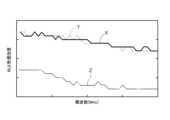
〔第2アンテナのアンテナ特性〕
次に、第2アンテナ20のアンテナ特性について説明する。図4には、第2アンテナ20のアンテナ特性の一例が示される。図4では、縦軸を第2アンテナ20の受信強度とし、横軸を周波数としている。[Antenna characteristics of the second antenna]
Next, a description will be given of the antenna characteristics of the
図4には、第1の実施形態のように電極50を第2アンテナ20の側方に配置した場合や、第2実施形態のように電極50の第2アンテナ20と対向する部分を切り欠いて構成した場合(以下「構成X」とする)の第2アンテナ20のアンテナ特性が実線で示される。また、参考として、電極50を設けない場合(以下「構成Y」とする)の第2アンテナ20のアンテナ特性を破線で示し、平面視において電極50を通信部30と重複するように設け、且つ、第2アンテナ20と対向する部分を切り欠かずに構成した場合(以下「構成Z」とする)の第2アンテナ20のアンテナ特性を一点鎖線で示している。In FIG. 4, the antenna characteristics of the
図4に示されるように、構成Xとすることで、構成Zに対して受信強度を向上することが可能である。また、構成Xとした場合であっても、構成Yと同様の受信強度を実現できる。このように、本アンテナ装置1によれば、第2アンテナ20のアンテナ特性が悪化することなく構成することが可能である。As shown in FIG. 4, by using configuration X, it is possible to improve the reception strength compared to configuration Z. Furthermore, even with configuration X, it is possible to achieve a reception strength similar to that of configuration Y. In this way, according to the present antenna device 1, it is possible to configure the
〔その他の実施形態〕
上記実施形態では、第1アンテナ10が内部ケース40の支持プレート46に支持されるとして説明した。しかしながら、第1アンテナ10も、内部ケース40の椀状部42の収容部43に収容するように構成することも可能である。Other embodiments
In the above embodiment, the
上記実施形態では、第1アンテナ10及び第2アンテナ20の夫々は、接続部60を介して給電部により給電され、第2アンテナは、給電部側に設けられているとして説明した。しかしながら、第1アンテナ10と第2アンテナ20とは、互いに異なる接続部から給電されるように構成することも可能である。また、第2アンテナ20は、給電部側に設けなくてもよい。すなわち、ドアハンドル100の平面視において、前後方向における前側から、給電部、第1アンテナ10、第2アンテナ20の順に並んで設けてもよい。In the above embodiment, the
上記第1の実施形態では、静電容量センサ51の電極50が、内部ケース40における、第1アンテナ10及び第2アンテナ20の側方の側壁に設けられているとして説明した。しかしながら、静電容量センサ51は、内部ケース40における前側の壁部に設けることも可能であるし、後側の壁部に設けることも可能である。In the first embodiment described above, the
上記第2の実施形態では、静電容量センサ51の電極50が、平面視において通信部30と重複する状態で配置されているとして説明した。しかしながら、電極50は、送受信部15と重複するように配置することも可能である。In the second embodiment described above, the
上記第2の実施形態では、静電容量センサ51の電極50が、アンテナ装置1の最表面に設けられるとして説明した。しかしながら、静電容量センサ51の電極50は、アンテナ装置1の裏面側、すなわち、ドアパネル側に設けることも可能である。In the second embodiment described above, the
本発明は、車両のドアハンドル内に設けられるアンテナ装置に用いることが可能である。The present invention can be used in an antenna device installed in a vehicle door handle.
1:アンテナ装置
10:第1アンテナ
20:第2アンテナ
30:通信部(レシーバ)
40:内部ケース
50:電極
51:静電容量センサ
100:ドアハンドル
100A:把持部 1: Antenna device 10: First antenna 20: Second antenna 30: Communication unit (receiver)
40: Inner case 50: Electrode 51: Capacitive sensor 100: Door handle 100A: Grip portion
Claims (4)
Translated fromJapanese前記ドアハンドルの把持部に設けられ、第1周波数帯の電波を送信する第1アンテナと、
前記第1周波数帯よりも高い第2周波数帯の電波を受信する第2アンテナと、
前記第2アンテナで受信した前記電波に基づく信号の処理を行うレシーバと、
前記ドアハンドル内において、前記第2アンテナと前記レシーバとを収容する内部ケースと、を備え、
前記第1アンテナと前記第2アンテナとが前記内部ケースにおいて、前記ドアハンドルの長手方向に沿って並べて配置されているアンテナ装置。 An antenna device provided in a door handle of a vehicle,
A first antenna provided on a grip portion of the door handle and configured to transmit radio waves in a first frequency band;
a second antenna for receiving radio waves in a second frequency band higher than the first frequency band;
a receiver that processes a signal based on the radio wave received by the second antenna;
an inner case that is disposed within the door handle and that houses the second antenna and the receiver;
The antenna device, wherein the first antenna and the second antenna are arranged side by side in the inner case along the longitudinal direction of the door handle.
前記第2アンテナは、前記給電部側に設けられている請求項1に記載のアンテナ装置。 each of the first antenna and the second antenna is fed by a feeding section via a connecting section;
The antenna device according to claim 1 , wherein the second antenna is provided on a side of the power supply portion.
前記電極は、前記内部ケースにおける、前記第1アンテナ及び前記第2アンテナの側方の側壁に設けられている請求項1又は2に記載のアンテナ装置。 An electrode of a capacitance sensor is provided in the door handle,
3. The antenna device according to claim 1, wherein the electrodes are provided on side walls of the inner case on sides of the first antenna and the second antenna.
前記電極は、前記車両のドアと対向して設けられ、前記第2アンテナと対向する部分が切り欠かれている請求項1又は2に記載のアンテナ装置。 An electrode of a capacitance sensor is provided in the door handle,
3. The antenna device according to claim 1, wherein the electrode is provided opposite a door of the vehicle, and a portion facing the second antenna is cut out.
Priority Applications (4)
| Application Number | Priority Date | Filing Date | Title |
|---|---|---|---|
| JP2023045676AJP2024135139A (en) | 2023-03-22 | 2023-03-22 | Antenna Device |
| US18/441,016US20240322423A1 (en) | 2023-03-22 | 2024-02-14 | Antenna device |
| DE102024105758.0ADE102024105758A1 (en) | 2023-03-22 | 2024-02-29 | Antenna device |
| CN202410326806.3ACN118693507A (en) | 2023-03-22 | 2024-03-21 | Antenna device |
Applications Claiming Priority (1)
| Application Number | Priority Date | Filing Date | Title |
|---|---|---|---|
| JP2023045676AJP2024135139A (en) | 2023-03-22 | 2023-03-22 | Antenna Device |
Publications (1)
| Publication Number | Publication Date |
|---|---|
| JP2024135139Atrue JP2024135139A (en) | 2024-10-04 |
Family
ID=92634144
Family Applications (1)
| Application Number | Title | Priority Date | Filing Date |
|---|---|---|---|
| JP2023045676APendingJP2024135139A (en) | 2023-03-22 | 2023-03-22 | Antenna Device |
Country Status (4)
| Country | Link |
|---|---|
| US (1) | US20240322423A1 (en) |
| JP (1) | JP2024135139A (en) |
| CN (1) | CN118693507A (en) |
| DE (1) | DE102024105758A1 (en) |
Family Cites Families (5)
| Publication number | Priority date | Publication date | Assignee | Title |
|---|---|---|---|---|
| JP2001345615A (en)* | 2000-05-31 | 2001-12-14 | Aisin Seiki Co Ltd | Door handle built-in antenna |
| JP2008079118A (en)* | 2006-09-22 | 2008-04-03 | Alpha Corp | Vehicle antenna apparatus |
| JP5556620B2 (en)* | 2010-11-26 | 2014-07-23 | アイシン精機株式会社 | Door handle device |
| JP6977443B2 (en) | 2017-09-26 | 2021-12-08 | 株式会社Soken | Composite antenna device |
| JP7639366B2 (en) | 2021-01-28 | 2025-03-05 | 株式会社デンソー | Electronic Key System |
- 2023
- 2023-03-22JPJP2023045676Apatent/JP2024135139A/enactivePending
- 2024
- 2024-02-14USUS18/441,016patent/US20240322423A1/enactivePending
- 2024-02-29DEDE102024105758.0Apatent/DE102024105758A1/enactivePending
- 2024-03-21CNCN202410326806.3Apatent/CN118693507A/enactivePending
Also Published As
| Publication number | Publication date |
|---|---|
| US20240322423A1 (en) | 2024-09-26 |
| DE102024105758A1 (en) | 2024-09-26 |
| CN118693507A (en) | 2024-09-24 |
Similar Documents
| Publication | Publication Date | Title |
|---|---|---|
| CN1893184B (en) | Vehicle anti-theft system incorporated with internal antennas | |
| US8614645B2 (en) | Antenna module for a motor vehicle | |
| JP5046025B2 (en) | Smart keyless entry system | |
| JP2546842B2 (en) | Vehicle locking / unlocking control device | |
| EP1513109B1 (en) | Remote door lock controller for vehicles | |
| US20050159131A1 (en) | Communicator and vehicle controller | |
| JP2015101908A (en) | Keyless entry system | |
| JP2004060191A (en) | Vehicle door handle | |
| EP1467436A2 (en) | Antenna device for vehicles and vehicle antenna system and communication system using the antenna device | |
| JP5088026B2 (en) | Smart keyless entry system | |
| CN113202363B (en) | Locking and unlocking assembly and door handle assembly | |
| JP2024135139A (en) | Antenna Device | |
| US6937197B2 (en) | Antenna for a central locking system of an automotive vehicle | |
| US9495816B2 (en) | Mobile device | |
| US20070222557A1 (en) | Vehicle antenna device, vehicle including the vehicle antenna device, and vehicle security system including the vehicle antenna device | |
| KR101264982B1 (en) | Smart entry system for vehicle | |
| JP2004244851A (en) | Remote control system | |
| JP2009030337A (en) | Smart keyless entry system | |
| EP1533865B1 (en) | On-board signal transmitter for implementing keyless procedure | |
| JP2002370584A (en) | Vehicle door with built-in antenna | |
| JP4862350B2 (en) | Antenna device and communication system using the same | |
| JP2001303819A (en) | Keyless entry device for automobile | |
| JP2006063571A (en) | Electronic key device for vehicle | |
| JP2005124070A (en) | Remote controller | |
| JP2000031726A (en) | On-vehicle communication equipment |