JP2024135055A - Wire harnesses and wire protection parts - Google Patents
Wire harnesses and wire protection partsDownload PDFInfo
- Publication number
- JP2024135055A JP2024135055AJP2023045554AJP2023045554AJP2024135055AJP 2024135055 AJP2024135055 AJP 2024135055AJP 2023045554 AJP2023045554 AJP 2023045554AJP 2023045554 AJP2023045554 AJP 2023045554AJP 2024135055 AJP2024135055 AJP 2024135055A
- Authority
- JP
- Japan
- Prior art keywords
- wire
- electromagnetic wave
- wave absorbing
- electric wire
- protection member
- Prior art date
- Legal status (The legal status is an assumption and is not a legal conclusion. Google has not performed a legal analysis and makes no representation as to the accuracy of the status listed.)
- Pending
Links
Images


Classifications
- H—ELECTRICITY
- H02—GENERATION; CONVERSION OR DISTRIBUTION OF ELECTRIC POWER
- H02G—INSTALLATION OF ELECTRIC CABLES OR LINES, OR OF COMBINED OPTICAL AND ELECTRIC CABLES OR LINES
- H02G3/00—Installations of electric cables or lines or protective tubing therefor in or on buildings, equivalent structures or vehicles
- H02G3/02—Details
- H02G3/04—Protective tubing or conduits, e.g. cable ladders or cable troughs
- H—ELECTRICITY
- H05—ELECTRIC TECHNIQUES NOT OTHERWISE PROVIDED FOR
- H05K—PRINTED CIRCUITS; CASINGS OR CONSTRUCTIONAL DETAILS OF ELECTRIC APPARATUS; MANUFACTURE OF ASSEMBLAGES OF ELECTRICAL COMPONENTS
- H05K9/00—Screening of apparatus or components against electric or magnetic fields
Landscapes
- Engineering & Computer Science (AREA)
- Architecture (AREA)
- Civil Engineering (AREA)
- Structural Engineering (AREA)
- Microelectronics & Electronic Packaging (AREA)
- Details Of Indoor Wiring (AREA)
- Shielding Devices Or Components To Electric Or Magnetic Fields (AREA)
Abstract
Description
Translated fromJapanese本発明は、ワイヤハーネス及び電線保護部材に関する。The present invention relates to a wire harness and a wire protection member.
従来、特許文献1に開示されるように、編組シールドで覆われた複数の電線に筒状の電磁波吸収部品が取付けられた配線部材が周知である。この配線部材は、電磁波吸収部品と編組シールドとの相対的な位置を固定する位置固定部材を有する。配線部材は、ブラケットによって位置固定部材が車両の車体に固定されている。As disclosed in Patent Document 1, a wiring member in which a cylindrical electromagnetic wave absorbing component is attached to multiple electric wires covered with a braided shield is known. This wiring member has a position fixing member that fixes the relative positions of the electromagnetic wave absorbing component and the braided shield. The position fixing member of the wiring member is fixed to the vehicle body by a bracket.
ところで、電線は、挿入された電磁波吸収部品がブラケットに吊り下げられた構成となっている。また、電磁波吸収部品は、電磁波を十分に抑制するために、ある程度の大きさを有している。このため、走行中に車両が振動すると、電磁波吸収部品によって電線が揺さぶられるので、電線が損傷する可能性があった。The electric wires are configured so that the electromagnetic wave absorbing parts inserted into them are suspended from the bracket. The electromagnetic wave absorbing parts also have a certain size in order to adequately suppress electromagnetic waves. For this reason, when the vehicle vibrates while in motion, the electric wires are shaken by the electromagnetic wave absorbing parts, which can cause damage to the electric wires.
本開示の目的は、電線を損傷し難くできるワイヤハーネス及び電線保護部材を提供することにある。The objective of this disclosure is to provide a wire harness and a wire protection member that can prevent damage to wires.
前記課題を解決するワイヤハーネスは、電線と、前記電線に取付けられた電磁波吸収部材と、前記電線及び前記電磁波吸収部材を周囲から覆う編組と、筒状の第1保護部材の端部に一端が固定されつつ筒状の第2保護部材の端部に他端が固定されるとともに、前記電線において前記電磁波吸収部材が位置する吸収部を収容する外装部材と、前記外装部材を前記吸収部の部位において取付け先に固定する固定部材と、を備えた構成であって、前記電線と前記電磁波吸収部材との間に設けられ、前記電磁波吸収部材の揺れに対して前記電線を保護する電線保護部材を備える。The wire harness that solves the above problem includes an electric wire, an electromagnetic wave absorbing member attached to the electric wire, a braid that surrounds the electric wire and the electromagnetic wave absorbing member, an exterior member that is fixed at one end to an end of a cylindrical first protective member and at the other end to an end of a cylindrical second protective member, and that houses an absorbing section of the electric wire where the electromagnetic wave absorbing member is located, and a fixing member that fixes the exterior member to the attachment destination at the site of the absorbing section, and includes an electric wire protection member that is provided between the electric wire and the electromagnetic wave absorbing member and protects the electric wire from the vibration of the electromagnetic wave absorbing member.
前記課題を解決する電線保護部材は、電線と、前記電線に取付けられた電磁波吸収部材と、前記電線及び前記電磁波吸収部材を周囲から覆う編組と、筒状の第1保護部材の端部に一端が固定されつつ筒状の第2保護部材の端部に他端が固定されるとともに、前記電線において前記電磁波吸収部材が位置する吸収部を収容する外装部材と、前記外装部材を前記吸収部の部位において取付け先に固定する固定部材と、を備えたワイヤハーネスに使用される構成であって、前記電線と前記電磁波吸収部材との間に設けられ、前記電磁波吸収部材の揺れに対して前記電線を保護する。The wire protection member that solves the above problem is configured for use in a wire harness that includes an electric wire, an electromagnetic wave absorbing member attached to the electric wire, a braid that surrounds the electric wire and the electromagnetic wave absorbing member, an exterior member that is fixed at one end to an end of a cylindrical first protective member and at the other end to an end of a cylindrical second protective member, and that houses an absorbing section of the electric wire where the electromagnetic wave absorbing member is located, and a fixing member that fixes the exterior member to the attachment destination at the absorbing section, and is provided between the electric wire and the electromagnetic wave absorbing member to protect the electric wire from vibration of the electromagnetic wave absorbing member.
本開示は、電線を損傷し難くできる。This disclosure makes it less likely that electrical wires will be damaged.
最初に本開示の実施態様を列記して説明する。
[1]本開示のワイヤハーネスは、電線と、前記電線に取付けられた電磁波吸収部材と、前記電線及び前記電磁波吸収部材を周囲から覆う編組と、筒状の第1保護部材の端部に一端が固定されつつ筒状の第2保護部材の端部に他端が固定されるとともに、前記電線において前記電磁波吸収部材が位置する吸収部を収容する外装部材と、前記外装部材を前記吸収部の部位において取付け先に固定する固定部材と、を備えた構成であって、前記電線と前記電磁波吸収部材との間に設けられ、前記電磁波吸収部材の揺れに対して前記電線を保護する電線保護部材を備える。 First, the embodiments of the present disclosure will be listed and described.
[1] A wire harness according to the present disclosure includes an electric wire, an electromagnetic wave absorbing member attached to the electric wire, a braid surrounding the electric wire and the electromagnetic wave absorbing member, an outer casing having one end fixed to an end of a cylindrical first protective member and the other end fixed to an end of a cylindrical second protective member, the outer casing housing an absorbing section of the electric wire where the electromagnetic wave absorbing member is located, and a fixing member fixing the outer casing to an attachment location at the absorbing section, and further including a wire protection member provided between the electric wire and the electromagnetic wave absorbing member to protect the electric wire against vibration of the electromagnetic wave absorbing member.
本構成によれば、例えば、ワイヤハーネスに振動が付与されて電磁波吸収部材によって電線が振られた場合であっても、電線保護部材によって電線を電磁波吸収部材から保護することが可能となる。よって、電線を損傷し難くすることが可能となる。According to this configuration, for example, even if the wire harness is subjected to vibrations and the electromagnetic wave absorbing member causes the electric wires to vibrate, the electric wire protection member can protect the electric wires from the electromagnetic wave absorbing member. This makes it possible to prevent the electric wires from being damaged.
[2]上記[1]において、前記電線保護部材の少なくとも一部は、前記電線を挿入するために環状に形成されている。この構成によれば、電線保護部材に電線を挿入する構造とすることが可能となるので、電線保護部材を電線から脱落し難くすることが可能となる。[2] In the above [1], at least a portion of the wire protection member is formed in a ring shape for inserting the wire. With this configuration, it is possible to form a structure in which the wire is inserted into the wire protection member, making it possible to make the wire protection member less likely to fall off the wire.
[3]上記[2]において、前記電線保護部材は、前記電線を挿入する環状部と、前記電磁波吸収部材を取付けるために前記環状部から前記電線に沿って延びるように形成された取付部と、を有する。この構成によれば、電磁波吸収部材を取付けるための取付部が電線保護部材に設けられているので、電磁波吸収部材を容易に脱落することなく電線保護部材に取付けることが可能となる。[3] In the above [2], the wire protection member has an annular portion into which the wire is inserted, and an attachment portion formed to extend from the annular portion along the wire to attach the electromagnetic wave absorbing member. With this configuration, the attachment portion for attaching the electromagnetic wave absorbing member is provided on the wire protection member, so that the electromagnetic wave absorbing member can be attached to the wire protection member without easily falling off.
[4]上記[3]において、前記固定部材は、前記外装部材を前記環状部の部位において前記取付け先に固定する。この構成によれば、固定部材の押圧によって外装部材が電線保護部材の環状部に密着した状態で、固定部材が取付け先に固定される。このように、ワイヤハーネスが電線保護部材を介して取付け先に固定されるので、電線保護部材の環状部を座として、ワイヤハーネスを取付け先に強固に固定することが可能となる。[4] In the above [3], the fixing member fixes the exterior member to the attachment destination at the annular portion. According to this configuration, the fixing member is fixed to the attachment destination in a state in which the exterior member is in close contact with the annular portion of the wire protection member by pressing the fixing member. In this way, the wire harness is fixed to the attachment destination via the wire protection member, and the annular portion of the wire protection member serves as a seat, making it possible to firmly fix the wire harness to the attachment destination.
[5]上記[3]において、前記取付部は、前記環状部の一部から部分的に突出するように形成された複数の舌片部である。この構成によれば、舌片部を弾性変形させながら電磁波吸収部材を電線保護部材に取付けることが可能となるので、電磁波吸収部材をスムーズに取付けることが可能となる。また、電線保護部材に取付部が形成されていても、取付部として舌片部が局所的に形成されるので、電線保護部材の重量が大きく増加することがない。[5] In the above [3], the mounting portion is a plurality of tongue portions formed to partially protrude from a part of the annular portion. With this configuration, it is possible to mount the electromagnetic wave absorbing member to the wire protection member while elastically deforming the tongue portions, so that it is possible to mount the electromagnetic wave absorbing member smoothly. In addition, even if the mounting portion is formed on the wire protection member, the tongue portions are formed locally as the mounting portion, so that the weight of the wire protection member does not increase significantly.
[6]上記[5]において、前記複数の舌片部の少なくとも1つの先端には、前記電磁波吸収部材の軸方向の移動を規制する突起が形成されている。この構成によれば、電線保護部材に設けた突起によって、電線保護部材に取付けられた電磁波吸収部材を電線保護部材から脱落し難くすることが可能となる。[6] In the above [5], a protrusion is formed on the tip of at least one of the plurality of tongue portions to restrict the axial movement of the electromagnetic wave absorbing member. With this configuration, the protrusion provided on the electric wire protection member makes it possible to make it difficult for the electromagnetic wave absorbing member attached to the electric wire protection member to fall off from the electric wire protection member.
[7]上記[1]から[6]のいずれかにおいて、前記電線保護部材は、外面に前記電磁波吸収部材を嵌合するための凹部を有する。この構成によれば、電磁波吸収部材が電線保護部材の凹部に嵌合されるので、電磁波吸収部材を電線保護部材から脱落し難くすることが可能となる。[7] In any of the above [1] to [6], the wire protection member has a recess on the outer surface for fitting the electromagnetic wave absorbing member. With this configuration, the electromagnetic wave absorbing member is fitted into the recess of the wire protection member, making it possible to make the electromagnetic wave absorbing member less likely to fall off the wire protection member.
[8]上記[1]から[7]のいずれかにおいて前記電線保護部材は、前記電線保護部材を前記電線に固定するのに用いる保護固定材を取付けるための延出部を有する。この構成によれば、保護固定材によって電線が電線保護部材の延出部に固定されるので、電線と電線保護部材とを強固に固定することが可能となる。[8] In any of the above [1] to [7], the wire protection member has an extension for attaching a protective fixing material used to fix the wire protection member to the wire. With this configuration, the wire is fixed to the extension of the wire protection member by the protective fixing material, so that the wire and the wire protection member can be firmly fixed.
[9]本開示の電線保護部材は、電線と、前記電線に取付けられた電磁波吸収部材と、前記電線及び前記電磁波吸収部材を周囲から覆う編組と、筒状の第1保護部材の端部に一端が固定されつつ筒状の第2保護部材の端部に他端が固定されるとともに、前記電線において前記電磁波吸収部材が位置する吸収部を収容する外装部材と、前記外装部材を前記吸収部の部位において取付け先に固定する固定部材と、を備えたワイヤハーネスに使用される構成であって、前記電線と前記電磁波吸収部材との間に設けられ、前記電磁波吸収部材の揺れに対して前記電線を保護する。本構成によれば、ワイヤハーネスの作用効果と同様の作用効果を得ることが可能となる。[9] The wire protection member of the present disclosure is configured for use in a wire harness including an electric wire, an electromagnetic wave absorbing member attached to the electric wire, a braid surrounding the electric wire and the electromagnetic wave absorbing member, an exterior member having one end fixed to an end of a cylindrical first protective member and the other end fixed to an end of a cylindrical second protective member, housing an absorbing section of the electric wire where the electromagnetic wave absorbing member is located, and a fixing member for fixing the exterior member to a mounting destination at the absorbing section, and is provided between the electric wire and the electromagnetic wave absorbing member to protect the electric wire from the vibration of the electromagnetic wave absorbing member. With this configuration, it is possible to obtain an effect similar to that of a wire harness.
[本開示の実施形態の詳細]
本開示の具体例を、以下に図面を参照しつつ説明する。なお、本発明はこれらの例示に限定されるものではなく、特許請求の範囲によって示され、特許請求の範囲と均等の意味および範囲内でのすべての変更が含まれることが意図される。各図面では、説明の便宜上、構成の一部を誇張又は簡略化して示す場合がある。また、各部分の寸法比率についても、実際とは異なる場合がある。 [Details of the embodiment of the present disclosure]
Specific examples of the present disclosure will be described below with reference to the drawings. Note that the present invention is not limited to these examples, but is indicated by the claims, and is intended to include all modifications within the meaning and scope equivalent to the claims. In each drawing, for convenience of explanation, some of the configurations may be exaggerated or simplified. In addition, the dimensional ratios of each part may differ from the actual ones.
(ワイヤハーネス1)
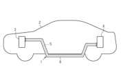
図1に示すように、車両2は、車両2の電気配線の一種としてワイヤハーネス1を備える。ワイヤハーネス1は、例えば、車両2に設けられた第1電装品3と第2電装品4とを電気接続する電線5と、電線5を収容する筒状の電線保護部6と、を備える。電線保護部6は、例えば、一部が車体床面から外部に露出するように配策されている。ワイヤハーネス1は、例えば、二次元状または三次元状に屈曲した経路に形成されている。 (Wire harness 1)
1, a
(第1保護部材9、第2保護部材10)
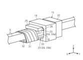
図2に示すように、ワイヤハーネス1は、第1保護部材9、第2保護部材10、及び外装部材11を備える。本例の場合、第1保護部材9、第2保護部材10、及び外装部材11が電線保護部6を構成する。 (First
2 , the wire harness 1 includes a first
第1保護部材9は、内部に電線5を収容する筒状、具体的には、略円筒状に形成されている。第1保護部材9は、例えば、コルゲートチューブである。第1保護部材9は、例えば、電線5の外周を周方向全域に亘って取り囲むように形成されている。第1保護部材9は、長さ方向(図2のX軸方向)に沿って凸及び凹が交互に配置された蛇腹状に形成されている。第1保護部材9の材料は、例えば、導電性樹脂材料であってもよいし、非導電性樹脂材料であってもよい。樹脂材料は、例えば、ポリオレフィン、ポリアミド、ポリエステル、ABS樹脂などの合成樹脂が使用される。The first
第2保護部材10は、第1保護部材9とともに電線5を収容するために、第1保護部材9と同軸上に配置されている。本例の場合、第2保護部材10は、第1保護部材9と同じ部材、具体的には、コルゲートチューブが使用される。よって、第2保護部材10は、第1保護部材9と同じ部材が使用されているため、説明を省略する。第1保護部材9及び第2保護部材10は、所定の間隔を空けて配置されている。The second
(外装部材11)
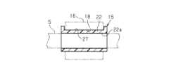
図2に示す通り、外装部材11は、第1保護部材9の端部と第2保護部材10の端部とに両端の各々が固定されるとともに、内部に電線5を収容する。外装部材11は、第1保護部材9の端部と、第2保護部材10の端部と、に架け渡されるように設けられている。外装部材11は、両端が開口した略円筒状に形成されている。具体的には、外装部材11は、一端の開口部11aに第1保護部材9が嵌合されるとともに、他端の開口部11bに第2保護部材10が嵌合されている。外装部材11は、中央部が両端よりも径方向外側に所定量膨らんだ形状に形成されている。 (Exterior member 11)
As shown in Fig. 2, the
外装部材11は、例えば、比較的硬度の高い弾性材料が使用される。弾性材料は、例えば、エチレンプロピレンジエンゴム等のゴムやエラストマが使用される。このように、外装部材11は、樹脂材料やゴム材料が使用される。The
外装部材11は、一端が第1固定具12によって第1保護部材9に固定されるとともに、他端が第2固定具13によって第2保護部材10に固定されている。第1固定具12及び第2固定具13は、例えば、樹脂製又は金属製の結束バンドが使用される。なお、第1固定具12及び第2固定具13は、例えば、カシメリングやテープ部材などを使用してもよい。One end of the
第1固定具12及び第2固定具13は、外装部材11の各端部を外周から締め付けるようにして取付けられる。具体的には、第1固定具12及び第2固定具13は、外装部材11の外周面に液密状に密着して固定される。よって、第1保護部材9と外装部材11との間の隙間、及び、第2保護部材10と外装部材11との隙間から、水等が浸入することが抑制される。The
(電線5)
図2に示す通り、電線5は、第1保護部材9、第2保護部材10、及び外装部材11の内部に収容されている。電線5は、例えば、高電圧及び大電流を印加する高圧電線である。電線5には、外装部材11の内部に収容される部位に、電線保護部材15を介して電磁波吸収部材16が取付けられている。このように、電線5と電磁波吸収部材16との間には、電線5を電磁波吸収部材16から保護するための電線保護部材15が設けられている。 (Electric wire 5)
2 , the
電線5は、例えば、芯線の周囲が絶縁被覆で覆われた電線構造を有する。芯線は、例えば、撚り線、柱状導体、筒状導体、及びこれらの組み合わせなどが使用される。芯線の材料は、例えば、銅系やアルミニウム系などの金属材料が使用される。絶縁被覆は、例えば、合成樹脂などの絶縁材料が使用される。絶縁被覆の材料は、例えば、架橋ポリエチレンや架橋ポリプロピレンなどのポリオレフィン系樹脂を主成分とする合成樹脂が使用される。The
電線5は、例えば、複数本であってもよいし、1本であってもよい。なお、本例の場合、電線5の本数は、複数本である。電線5は、例えば、電磁シールド構造であってもよいし、非電磁シールド構造であってもよい。The
(電磁波吸収部材16)
図2に示す通り、電磁波吸収部材16は、電線5において外装部材11に収容された部位に配置されている。電磁波吸収部材16の外面は、編組17によって被覆されている。電磁波吸収部材16は、電線5及び電線保護部材15が通される孔18を有する筒状に形成されている。電磁波吸収部材16は、例えば、略円筒状に形成されている。電磁波吸収部材16は、第1保護部材9及び第2保護部材10から離間して配置されている。電磁波吸収部材16は、例えば、電線5から放射される電磁波の一部を吸収する。電磁波は、例えば、電磁ノイズである。 (Electromagnetic wave absorbing member 16)
As shown in Fig. 2, the electromagnetic
電磁波吸収部材16は、例えば、円環状の磁性体コアである。磁性体コアは、例えば、電線5から放射される電磁波を吸収するとともに、振動等の力学的エネルギーや熱エネルギーに変換する。これにより、電線5から放射される電磁波が周辺の機器等に影響を与え難くなる。The electromagnetic
磁性体コアは、例えば、軟磁性材料を含む成形体である。軟磁性材料は、例えば、鉄(Fe)、鉄合金、フェライトなどが挙げられる。鉄合金は、例えば、Fe-ケイ素(Si)合金、Fe-ニッケル(Ni)合金などが挙げられる。磁性体コアは、例えば、フェライトコア、アモルファスコア、パーマロイコアが使用される。フェライトコアは、例えば、軟磁性を示すソフトフェライトからなる。ソフトフェライトは、例えば、ニッケル(Ni)と亜鉛(Zn)を含むフェライトや、マンガン(Mn)と亜鉛(Zn)を含むフェライトが挙げられる。磁性体コアの材料は、例えば、低減したい電磁ノイズの周波数帯に応じて適宜選択される。The magnetic core is, for example, a molded body containing a soft magnetic material. Examples of the soft magnetic material include iron (Fe), iron alloys, and ferrite. Examples of the iron alloy include Fe-silicon (Si) alloys and Fe-nickel (Ni) alloys. Examples of the magnetic core include a ferrite core, an amorphous core, and a permalloy core. The ferrite core is, for example, made of soft ferrite that exhibits soft magnetism. Examples of the soft ferrite include ferrite containing nickel (Ni) and zinc (Zn), and ferrite containing manganese (Mn) and zinc (Zn). The material of the magnetic core is, for example, appropriately selected depending on the frequency band of the electromagnetic noise to be reduced.
(編組17)
図2に示す通り、編組17は、電線5と電磁波吸収部材16の両方を覆うように筒状に形成されている。編組17は、例えば、電線5の長さ方向(図2のX軸方向)の略全長に亘って電線5を取り囲むように形成されている。編組17は、例えば、電磁波吸収部材16を被覆する部分の外形が、他の部分の外径に比べて大きくなった形状に形成されている。電線保護部材15、電磁波吸収部材16及び編組17が取付けられた電線5は、第1保護部材9、第2保護部材10、及び外装部材11によって形成された内部空間19に収容されている。 (Braid 17)
As shown in Fig. 2, the
編組17は、例えば、複数の金属素線が編成された編組部材、金属素線と樹脂素線とを組み合わせて編成された編組部材などが挙げられる。金属素線の材料は、例えば、銅系やアルミニウム系などの金属材料が使用される。樹脂素線は、例えば、パラ系アラミド繊維等の絶縁性及び耐剪断性に優れた強化繊維が使用される。The
(電線保護部材15)
図3~図5に示すように、電線保護部材15の少なくとも一部は、電線5を挿入するために環状に形成されている。本例の場合、電線保護部材15は、電線5を挿入する環状部22と、電磁波吸収部材16を取付けるために環状部22から前記電線に沿って延びるように形成された取付部23と、を有する。環状部22は、電線5を収容するための開口22a(図4等参照)を有する。開口22aは、例えば、複数の電線5を収容可能な大きさに形成されている。環状部22は、開口22aの軸方向(図4等のX軸方向)から見て、四角形状に形成されている。 (Electric wire protection member 15)
3 to 5, at least a portion of the
図4及び図5に示す通り、取付部23は、環状部22の一部から部分的に突出するように形成された複数の舌片部24である。本例の場合、舌片部24は、対向するように設けられた第1舌片部24a及び第2舌片部24bを含む。複数の舌片部24の少なくとも1つの先端には、電磁波吸収部材16の軸方向(図4のX軸方向)の移動を規制する突起25が形成されている。本例の場合、突起25は、第1舌片部24aの第1舌片本体26の先端に設けられている。舌片部24は、例えば、略板状に形成されている。As shown in Figures 4 and 5, the mounting
電線保護部材15は、外面に電磁波吸収部材16を嵌合するための凹部27を有する。本例の場合、凹部27は、環状部22の壁面28、第1舌片部24aの突起25、及び、第1舌片部24aの第1舌片本体26によって構成されている。The
電線保護部材15の材料は、例えば、樹脂、金属、ゴムなどが挙げられる。樹脂としては、例えば、ポリオレフィン、ポリアミド、ポリエステル、ABS樹脂などの合成樹脂が使用される。金属としては、例えば、鉄系や銅系などの金属材料が使用される。ゴムとしては、例えば、エチレンプロピレンジエンゴム等が使用される。Examples of the material for the electric
(吸収部30)
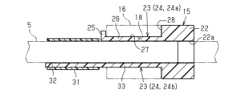
図2に示す通り、外装部材11は、電線5において電磁波吸収部材16が位置する吸収部30を収容する。吸収部30は、電磁波吸収部材16が取付けられている分だけ、電線5の他の部位に比較して大径に形成されている。なお、吸収部30は、電線5において、電線5、電線保護部材15、電磁波吸収部材16、及び編組17から構成された部位をいう。 (Absorbing section 30)
2 , the
(保護固定材31)
図3に示す通り、電線保護部材15は、保護固定材31によって電線5に固定されている。保護固定材31は、例えば、テープ(樹脂テープ)である。本例の場合、電線保護部材15は、電線保護部材15を電線5に固定するのに用いる保護固定材31を取付けるための延出部32を有する。延出部32は、第2舌片部24bの先端に設けられている。このように、第2舌片部24bは、電磁波吸収部材16を支持する第2舌片本体33と、第2舌片本体33の先端に設けられた延出部32と、を含む。なお、保護固定材31は、テープに限らず、例えば、樹脂製又は金属製の結束バンドや、かしめリングなどでもよい。 (Protective Fixing Material 31)
3, the
(取付け先34に対するワイヤハーネス1の固定構造)
図2に示す通り、ワイヤハーネス1は、ワイヤハーネス1を取付け先34に固定するための固定部材35を備える。本例の場合、ワイヤハーネス1は、外装部材11を支持した固定部材35によって取付け先34に固定されている。固定部材35は、吸収部30の部位において外装部材11を取付け先34に固定する。すなわち、ワイヤハーネス1は、電線保護部材15を支持する固定部材35を介して取付け先34に固定される。取付け先34は、例えば、車両ボディである。 (Fixing structure of wire harness 1 to mounting destination 34)
2, the wire harness 1 includes a fixing
固定部材35は、例えば、ワイヤハーネスクランプであることが好ましい。ワイヤハーネスクランプの場合、固定部材35は、外装部材11の外周に固定されるバンド部36と、取付け先34に固定される突起部37と、を有する。突起部37の頭部は、例えば、断面台形状や断面三角形状に形成されている。突起部37は、取付け先34に形成された取付凹部38に係合される。取付凹部38は、例えば、貫通した孔である。The fixing
次に、本実施形態のワイヤハーネス1(電線保護部材15)の作用について説明する。
(電磁波吸収部材16の電線5への取付け)
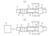
図6(a)に示すように、まずは、電線保護部材15に電線5を挿入する。電線5の挿入後、電線保護部材15は、延出部32の部位で保護固定材31によって電線5に固定される。保護固定材31がテープの場合、電線5と延出部32とにテープを巻き付けることにより、電線保護部材15が電線5に固定される。 Next, the operation of the wire harness 1 (wire protection member 15) of this embodiment will be described.
(Attachment of the electromagnetic
6( a ), first, the
図6(b)に示すように、電線保護部材15を取付けた電線5は、電磁波吸収部材16の孔18に挿入される。本例の場合、先端に突起25を有する第1舌片部24aが電磁波吸収部材16の孔18の内面によって倒されながら、電線5及び電線保護部材15が挿入される。そして、電磁波吸収部材16の端面が電線保護部材15の壁面28に接触するまで挿入されると、孔18の内面との接触が開放されて第1舌片部24aが起き上がり、先端の突起25が電磁波吸収部材16に係合する。これにより、電磁波吸収部材16が電線保護部材15の凹部27に嵌合される。As shown in FIG. 6(b), the
図2に示す通り、電磁波吸収部材16及び電線保護部材15が取付けられた電線5は、外周に編組17が取付けられた後、第1保護部材9、第2保護部材10、及び外装部材11の内部に収容される。なお、外装部材11の一端と第1保護部材9の端部と連結部分は、第1固定具12が取付けられて固定される。また、外装部材11の他端と第2保護部材10の端部と連結部分は、第2固定具13が取付けられて固定される。以上のようにして、ワイヤハーネス1が組み立てられる。As shown in FIG. 2, the
(電線保護部材15の機能)
図2に示す通り、ワイヤハーネス1は、内部に電線保護部材15が位置する部位において、外装部材11が固定部材35によって取付け先34に固定される。具体的には、固定部材35のバンド部36を、内部に電線保護部材15が位置する部位で外装部材11の外周面に巻き付けるとともに、固定部材35の突起部37を取付凹部38に係合することにより、ワイヤハーネス1を取付け先34に固定する。 (Function of wire protection member 15)
2 , in the wire harness 1, the
ところで、ワイヤハーネス1は、取付け先34から固定部材35によって吊り下げられた状態となるので、車両2の走行時に、加速度や遠心力などによって、揺れが生じる。これにより、体格のある電磁波吸収部材16が揺さぶられるので、電磁波吸収部材16によって電線5が損傷してしまう可能性がある。The wire harness 1 is suspended from the
そこで、本例の場合、電線5と電磁波吸収部材16との間に電線保護部材15を設けている。これにより、例えば、電磁波吸収部材16が揺さぶられたとしても、電磁波吸収部材16からの負荷や荷重が電線保護部材15によって電線5に伝わり難くなる。よって、電線5の損傷を生じ難くすることが可能となる。Therefore, in this example, a
(実施形態の効果)
上記実施形態の構成によれば、以下のような効果を得ることができる。
(1)ワイヤハーネス1は、電線5、外装部材11、電線保護部材15、電磁波吸収部材16、編組17、及び固定部材35、を備える。電磁波吸収部材16は、電線5に取付けられている。編組17は、電線5及び電磁波吸収部材16を周囲から覆う。外装部材11は、筒状の第1保護部材9の端部に一端が固定されつつ筒状の第2保護部材10の端部に他端が固定されるとともに、電線5において電磁波吸収部材16が位置する吸収部30を収容する。固定部材35は、外装部材11を吸収部30の部位において取付け先34に固定する。電線保護部材15は、電線5と電磁波吸収部材16との間に設けられ、電磁波吸収部材16の揺れに対して電線5を保護する。 (Effects of the embodiment)
According to the configuration of the above embodiment, the following effects can be obtained.
(1) The wire harness 1 includes an
本構成によれば、例えば、ワイヤハーネス1に振動が付与されて電磁波吸収部材16によって電線5が振られた場合であっても、電線保護部材15によって電線5を電磁波吸収部材16から保護することが可能となる。よって、電線5を損傷し難くすることができる。According to this configuration, for example, even if vibration is applied to the wire harness 1 and the
(2)電線保護部材15の少なくとも一部は、電線5を挿入するために環状に形成されている。この構成によれば、電線保護部材15に電線5を挿入する構造とすることが可能となるので、電線保護部材15を電線5から脱落し難くすることができる。(2) At least a portion of the
(3)電線保護部材15は、電線5を挿入する環状部22と、電磁波吸収部材16を取付けるために環状部22から電線5に沿って延びるように形成された取付部23と、を有する。この構成によれば、電磁波吸収部材16を取付けるための取付部23が電線保護部材15に設けられているので、電磁波吸収部材16を容易に脱落することなく電線保護部材15に取付けることができる。(3) The
(4)固定部材35は、外装部材11を環状部22の部位において取付け先34に固定する。この構成によれば、固定部材35の押圧によって外装部材11が電線保護部材15の環状部22に密着した状態で、固定部材35が取付け先34に固定される。このように、ワイヤハーネス1が電線保護部材15を介して取付け先34に固定されるので、電線保護部材15の環状部22を座として、ワイヤハーネス1を取付け先34に強固に固定することができる。(4) The fixing
(5)取付部23は、環状部22の一部から部分的に突出するように形成された複数の舌片部24である。この構成によれば、舌片部24を弾性変形させながら電磁波吸収部材16を電線保護部材15に取付けることが可能となるので、電磁波吸収部材16をスムーズに取付けることができる。また、電線保護部材15に取付部23が形成されていても、取付部23として舌片部24が局所的に形成されるので、電線保護部材15の重量が大きく増加することがない。(5) The mounting
(6)複数の舌片部24の少なくとも1つの先端には、電磁波吸収部材16の軸方向の移動を規制する突起25が形成されている。この構成によれば、電線保護部材15に設けた突起25によって、電線保護部材15に取付けられた電磁波吸収部材16を電線保護部材15から脱落し難くすることができる。(6) At least one tip of the
(7)電線保護部材15は、外面に電磁波吸収部材16を嵌合するための凹部27を有する。この構成によれば、電磁波吸収部材16が電線保護部材15の凹部27に嵌合されるので、電磁波吸収部材16を電線保護部材15から脱落し難くすることができる。(7) The
(8)電線保護部材15は、電線保護部材15を電線5に固定するのに用いる保護固定材31を取付けるための延出部32を有する。この構成によれば、保護固定材31によって電線5が電線保護部材15の延出部32に固定されるので、電線5と電線保護部材15とを強固に固定することができる。(8) The
(他の実施形態)
なお、本実施形態は、以下のように変更して実施することができる。本実施形態及び以下の変更例は、技術的に矛盾しない範囲で互いに組み合わせて実施することができる。 Other Embodiments
This embodiment can be modified as follows: This embodiment and the following modifications can be combined with each other to the extent that no technical contradiction occurs.
・図7に示すように、電線保護部材15は、開口22aの軸方向から見て円形状に形成されてもよい。
・図8に示すように、舌片部24の基端は、環状部22と同じ厚さを有してもよい。 As shown in FIG. 7, the
As shown in FIG. 8 , the base end of the
・図9に示すように、舌片部24の数は、複数に限らず、例えば1つであってもよい。
・図10に示すように、延出部32は、舌片部24の先端に形成されることに限定されない。延出部32は、例えば、環状部22において舌片部24の反対側の位置に形成されてもよい。このように、延出部32は、電線保護部材15の任意の位置に形成できる。 As shown in FIG. 9 , the number of
10 , the extending
・図11に示すように、電線保護部材15は、環状部22に電磁波吸収部材16を嵌合するための凹部27が形成された形状でもよい。この場合、舌片部24を省略することが可能となるので、電線保護部材15を小型化できる。なお、凹部27は、環状部22の一部にのみ形成されることに限らず、環状部22の外周面全体に形成されてもよい。- As shown in FIG. 11, the
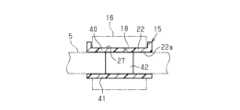
・図12に示すように、環状部22は、上壁40及び下壁41よりも幅狭の形状を有する連結部42によって、上壁40及び下壁41が連結された形状を有していてもよい。
・電線保護部材15は、開口22aの軸方向から見て、非環状に形成されてもよい。この場合の形状としては、例えば、電線保護部材15の開口22aの軸方向から見て略U状の形状などが挙げられる。 As shown in FIG. 12 , the
The
・取付部23は、舌片部24に限らず、例えば、周方向全体に形成された形状としてもよい。
・突起25は、第2舌片部24bに形成されてもよい。 The
The
・電磁波吸収部材16は、周方向一帯に形成された環状に限定されず、例えば、周方向の一部に形成された形状としてもよい。
・電磁波吸収部材16は、例えば、磁性体コアがホルダに取付けられた構造でもよい。 The electromagnetic
The electromagnetic
・外装部材11は、例えば、非筒状としてもよい。
・固定部材35は、複数設けられてもよい。
・固定部材35は、ワイヤハーネスクランプに限らず、ワイヤハーネス1を取付け先34に固定できる部材であればよい。 The
A plurality of fixing
The fixing
・取付け先34は、車両ボディに限定されず、他の部位に変更してもよい。
・ワイヤハーネス1は、車載部品に限定されず、他の機器や装置に使用されてもよい。
・本開示において使用される「少なくとも1つ」という表現は、所望の選択肢の「1つ以上」を意味する。一例として、本開示において使用される「少なくとも1つ」という表現は、選択肢の数が2つであれば「1つの選択肢のみ」または「2つの選択肢の双方」を意味する。他の例として、本開示において使用される「少なくとも1つ」という表現は、選択肢の数が3つ以上であれば「1つの選択肢のみ」または「2つ以上の任意の選択肢の組み合わせ」を意味する。 The
The wire harness 1 is not limited to being used in an in-vehicle component and may be used in other devices or apparatuses.
The term "at least one" as used in this disclosure means "one or more" of the desired options. As an example, the term "at least one" as used in this disclosure means "only one option" or "both of two options" if the number of options is two. As another example, the term "at least one" as used in this disclosure means "only one option" or "any combination of two or more options" if the number of options is three or more.
・本開示は、実施例に準拠して記述されたが、本開示は当該実施例や構造に限定されるものではないと理解される。本開示は、様々な変形例や均等範囲内の変形をも包含する。加えて、様々な組み合わせや形態、さらには、それらに一要素のみ、それ以上、あるいはそれ以下、を含む他の組み合わせや形態をも、本開示の範疇や思想範囲に入るものである。- Although the present disclosure has been described with reference to examples, it is understood that the present disclosure is not limited to those examples or structures. The present disclosure also encompasses various modifications and modifications within the scope of equivalents. In addition, various combinations and forms, as well as other combinations and forms that include only one element, more than one element, or less than one element, are also within the scope and concept of the present disclosure.
1 ワイヤハーネス
2 車両
3 第1電装品
4 第2電装品
5 電線
6 電線保護部
9 第1保護部材
10 第2保護部材
11 外装部材
11a 開口部
11b 開口部
12 第1固定具
13 第2固定具
15 電線保護部材
16 電磁波吸収部材
17 編組
18 孔
19 内部空間
22 環状部
22a 開口
23 取付部
24 舌片部
24a 第1舌片部
24b 第2舌片部
25 突起
26 第1舌片本体
27 凹部
28 壁面
30 吸収部
31 保護固定材
32 延出部
33 第2舌片本体
34 取付け先
35 固定部材
36 バンド部
37 突起部
38 取付凹部
40 上壁
41 下壁
42 連結部 REFERENCE SIGNS LIST 1
Claims (9)
Translated fromJapanese前記電線と前記電磁波吸収部材との間に設けられ、前記電磁波吸収部材の揺れに対して前記電線を保護する電線保護部材を備える、ワイヤハーネス。 a braid surrounding the electric wire and the electromagnetic wave absorbing member; an exterior member having one end fixed to an end of a cylindrical first protective member and the other end fixed to an end of a cylindrical second protective member, the exterior member housing an absorbing section of the electric wire where the electromagnetic wave absorbing member is located; and a fixing member fixing the exterior member to a mounting destination at a location of the absorbing section,
The wire harness further comprises a wire protection member provided between the electric wires and the electromagnetic wave absorbing member to protect the electric wires against vibration of the electromagnetic wave absorbing member.
前記電線を挿入する環状部と、
前記電磁波吸収部材を取付けるために前記環状部から前記電線に沿って延びるように形成された取付部と、を有する、請求項2に記載のワイヤハーネス。 The wire protection member includes:
an annular portion into which the electric wire is inserted;
The wire harness according to claim 2 , further comprising: a mounting portion formed to extend from the annular portion along the electric wires for mounting the electromagnetic wave absorbing member.
前記電線と前記電磁波吸収部材との間に設けられ、前記電磁波吸収部材の揺れに対して前記電線を保護する、電線保護部材。 a braid surrounding the electric wire and the electromagnetic wave absorbing member; an exterior member having one end fixed to an end of a cylindrical first protective member and the other end fixed to an end of a cylindrical second protective member, the exterior member housing an absorbing section of the electric wire where the electromagnetic wave absorbing member is located; and a fixing member fixing the exterior member to a mounting destination at a location of the absorbing section,
A wire protection member provided between the electric wire and the electromagnetic wave absorbing member to protect the electric wire against vibration of the electromagnetic wave absorbing member.
Priority Applications (2)
| Application Number | Priority Date | Filing Date | Title |
|---|---|---|---|
| JP2023045554AJP2024135055A (en) | 2023-03-22 | 2023-03-22 | Wire harnesses and wire protection parts |
| PCT/JP2024/008343WO2024195524A1 (en) | 2023-03-22 | 2024-03-05 | Wire harness and electric wire protection member |
Applications Claiming Priority (1)
| Application Number | Priority Date | Filing Date | Title |
|---|---|---|---|
| JP2023045554AJP2024135055A (en) | 2023-03-22 | 2023-03-22 | Wire harnesses and wire protection parts |
Publications (1)
| Publication Number | Publication Date |
|---|---|
| JP2024135055Atrue JP2024135055A (en) | 2024-10-04 |
Family
ID=92842041
Family Applications (1)
| Application Number | Title | Priority Date | Filing Date |
|---|---|---|---|
| JP2023045554APendingJP2024135055A (en) | 2023-03-22 | 2023-03-22 | Wire harnesses and wire protection parts |
Country Status (2)
| Country | Link |
|---|---|
| JP (1) | JP2024135055A (en) |
| WO (1) | WO2024195524A1 (en) |
Family Cites Families (5)
| Publication number | Priority date | Publication date | Assignee | Title |
|---|---|---|---|---|
| JP2014110343A (en)* | 2012-12-03 | 2014-06-12 | Kitagawa Ind Co Ltd | Ferrite clamp |
| JP6057176B2 (en)* | 2013-08-09 | 2017-01-11 | 住友電装株式会社 | holder |
| JP2021136274A (en)* | 2020-02-25 | 2021-09-13 | 住友電装株式会社 | Wiring harness |
| JP7363571B2 (en)* | 2020-02-25 | 2023-10-18 | 住友電装株式会社 | wire harness |
| JP7440899B2 (en)* | 2020-03-31 | 2024-02-29 | 北川工業株式会社 | Electromagnetic noise countermeasure components |
- 2023
- 2023-03-22JPJP2023045554Apatent/JP2024135055A/enactivePending
- 2024
- 2024-03-05WOPCT/JP2024/008343patent/WO2024195524A1/enactivePending
Also Published As
| Publication number | Publication date |
|---|---|
| WO2024195524A1 (en) | 2024-09-26 |
Similar Documents
| Publication | Publication Date | Title |
|---|---|---|
| US9622393B2 (en) | Wiring member | |
| US9718365B2 (en) | Wiring member | |
| CN112701631B (en) | Wire harness | |
| CN115151978B (en) | Wire harness | |
| JP7367559B2 (en) | wire harness | |
| US11322271B2 (en) | Wire harness with protector | |
| JP7363571B2 (en) | wire harness | |
| JP2017220972A (en) | Water cut-off structure of electric wire | |
| JP6819641B2 (en) | Wire harness | |
| JP2019179739A (en) | Wire harness | |
| JP2024135055A (en) | Wire harnesses and wire protection parts | |
| CN115136745B (en) | wiring harness | |
| JP7294465B2 (en) | Clamps and wire harnesses with clamps | |
| WO2024195440A1 (en) | Wire harness | |
| WO2021079545A1 (en) | Wire harness | |
| CN115136744A (en) | wiring harness | |
| CN115104384A (en) | wiring harness | |
| WO2021187054A1 (en) | Wire protection member and wire harness | |
| JP7151687B2 (en) | wire harness | |
| JP7558847B2 (en) | Wire harness and ground structure | |
| JP2024135054A (en) | Wire harness and electric wire fixing member | |
| JP2021136275A (en) | Wire harness | |
| JP2022184549A (en) | wire harness | |
| JP2008186648A (en) | Cable shield protection structure |
Legal Events
| Date | Code | Title | Description |
|---|---|---|---|
| A621 | Written request for application examination | Free format text:JAPANESE INTERMEDIATE CODE: A621 Effective date:20250717 |