JP2024134239A - Error rate measurement device and error rate measurement method - Google Patents
Error rate measurement device and error rate measurement methodDownload PDFInfo
- Publication number
- JP2024134239A JP2024134239AJP2023044441AJP2023044441AJP2024134239AJP 2024134239 AJP2024134239 AJP 2024134239AJP 2023044441 AJP2023044441 AJP 2023044441AJP 2023044441 AJP2023044441 AJP 2023044441AJP 2024134239 AJP2024134239 AJP 2024134239A
- Authority
- JP
- Japan
- Prior art keywords
- error rate
- signal
- unit
- symbol value
- calibration
- Prior art date
- Legal status (The legal status is an assumption and is not a legal conclusion. Google has not performed a legal analysis and makes no representation as to the accuracy of the status listed.)
- Granted
Links
Images


Landscapes
- Detection And Prevention Of Errors In Transmission (AREA)
- Dc Digital Transmission (AREA)
Abstract
Description
Translated fromJapanese本発明は、誤り率測定装置及び誤り率測定方法に関し、特に、被測定物から入力されるPAM4(Pulse Amplitude Modulation 4)信号の誤り率を測定する誤り率測定装置及び誤り率測定方法に関する。The present invention relates to an error rate measurement device and an error rate measurement method, and in particular to an error rate measurement device and an error rate measurement method for measuring the error rate of a PAM4 (Pulse Amplitude Modulation 4) signal input from a device under test.
近年、IoTやクラウドコンピューティングの普及により通信システムは膨大なデータを扱うようになり、通信システムを構成する各種の通信機器のインタフェースは高速化とシリアル伝送化が進んでいる。このような通信機器で採用されているUSB(登録商標)(Universal Serial Bus)やPCI Express(登録商標)(Peripheral Component Interconnect Express、以下、「PCIe」とも呼ぶ)などのハイスピードシリアルバス(High Speed Serial Bus)規格では、リンク状態管理機構(Link Training and Status State Machine:LTSSM)と呼ばれるステートマシンにより、デバイス間の通信の初期化やリンク速度の調整などが管理されている。In recent years, with the spread of IoT and cloud computing, communication systems have begun to handle huge amounts of data, and the interfaces of various communication devices that make up the communication systems are becoming faster and more serial in transmission. In high-speed serial bus standards such as USB (registered trademark) (Universal Serial Bus) and PCI Express (registered trademark) (Peripheral Component Interconnect Express, hereafter also referred to as "PCIe") that are used in such communication devices, initialization of communication between devices and adjustment of link speed are managed by a state machine called the Link Training and Status State Machine (LTSSM).
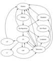
例えば、PCIeでは、LTSSMのステート遷移図は図6に示すようなものであり、ステートとして、L0、L0s、L1、L2、Detect、Polling(ポーリング)、Configuration、Disabled、Hot Reset、Loopback(ループバック)、Recoveryが定義されている。さらに、図7に示すように、Pollingには、Polling.Active、Polling.Configuration、Polling.Complianceの3つのサブステートが定義されている。Polling.Complianceは、被測定物(Device Under Test:DUT)からPCIe規格で定義されたコンプライアンスパターン(Compliance Pattern又はModified Compliance Pattern)を出力させるサブステートであり、コンプライアンスモードとも呼ばれる。For example, in PCIe, the state transition diagram of LTSSM is as shown in FIG. 6, and the states defined are L0, L0s, L1, L2, Detect, Polling, Configuration, Disabled, Hot Reset, Loopback, and Recovery. Furthermore, as shown in FIG. 7, Polling has three sub-states defined: Polling.Active, Polling.Configuration, and Polling.Compliance. Polling.Compliance is a sub-state that causes the device under test (DUT) to output a compliance pattern (Compliance Pattern or Modified Compliance Pattern) defined in the PCIe standard, and is also called compliance mode.
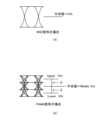
ハイスピードシリアルバス規格でよく使われる信号変調方式としてNRZ(Non Return to Zero)がある。NRZ信号のビット誤り率(Bit Error Rate:BER)を誤り率測定装置(例えば、特許文献1参照)で解析するにあたり、適切なVthとDelayの校正値を設定する必要がある。図8(a)に示すように、Vthは、NRZ信号のハイレベルとローレベルを判別するための閾値電圧であり、ほとんどの場合は振幅の中央値である0Vに固定される。Delayは、NRZ信号を打ち抜くクロック信号の立ち上がりと、NRZ信号のアイ開口の中心との時間差を表すパラメータであり、ボーレート(Baud rate)に依存することが知られている。NRZ (Non Return to Zero) is a signal modulation method often used in high-speed serial bus standards. When analyzing the bit error rate (BER) of an NRZ signal using an error rate measurement device (see, for example, Patent Document 1), it is necessary to set appropriate Vth and Delay calibration values. As shown in FIG. 8(a), Vth is the threshold voltage for distinguishing between high and low levels of an NRZ signal, and in most cases is fixed to 0 V, which is the median value of the amplitude. Delay is a parameter that represents the time difference between the rising edge of the clock signal that punches through the NRZ signal and the center of the eye opening of the NRZ signal, and is known to depend on the baud rate.
PCIeでは、PCIe Gen1~5までは信号変調方式としてNRZが採用されている。誤り率測定装置でBER測定等を実施するに当たっては、PCIe Gen1~5の互いに異なるボーレートごとにDelayの校正値を切り替えながらリンクトレーニングを実施して、DUTをLoopbackに持ち込む必要がある。For PCIe, NRZ is used as the signal modulation method for PCIe Gen1 to 5. When performing BER measurements using an error rate measurement device, it is necessary to perform link training while switching the delay calibration value for each of the different baud rates of PCIe Gen1 to 5, and then bring the DUT into Loopback.
PCIe Gen6では、信号変調方式としてPAM4が初めて採用され、リンクトレーニング中にPAM4信号をトレーニングパターンとして用いることとなった。PAM4信号は、0(00),1(01),2(10),3(11)からなる4値の論理レベルのシンボルで構成される。誤り率測定装置でPAM4信号のBER測定等をNRZ信号と同様に実施するためには、PAM4信号の論理レベルを解析した上でリンクトレーニングを実施して、DUTをLoopbackに持ち込む必要がある。PCIe Gen6 is the first to adopt PAM4 as a signal modulation method, and PAM4 signals are used as training patterns during link training. PAM4 signals are composed of symbols with four logical levels: 0 (00), 1 (01), 2 (10), and 3 (11). In order to perform BER measurements of PAM4 signals with an error rate measurement device in the same way as NRZ signals, it is necessary to analyze the logical level of the PAM4 signal, perform link training, and bring the DUT into Loopback.
PAM4信号を解析するためには、NRZ信号におけるVthに相当するMiddle Vthに加えて、適切なUpper/Lower Vthを閾値電圧の校正値として誤り率測定装置に設定する必要がある。なお、Middle VthはNRZ信号におけるVthと同様に中央値であり、通常0Vに設定される。Upper VthとLower Vthは、図8(b)に示すように、Middle Vthから±δV離れた位置に設定される。δは、DUT自体のロスと、DUTが装着されるCBB(Compliance Base Board)などのテストフィクスチャで模擬される信号経路のロスとの組合せロス量に依存する。To analyze a PAM4 signal, in addition to the Middle Vth, which is equivalent to the Vth in an NRZ signal, it is necessary to set appropriate Upper and Lower Vths as threshold voltage calibration values in the error rate measurement device. Note that the Middle Vth is the median value, like the Vth in an NRZ signal, and is usually set to 0V. The Upper Vth and Lower Vth are set at a position ±δV away from the Middle Vth, as shown in Figure 8(b). δ depends on the combined loss amount of the loss of the DUT itself and the loss of the signal path simulated by a test fixture such as a CBB (Compliance Base Board) to which the DUT is attached.
例えばPCIe Gen6のようなハイスピードシリアルバス規格では、PAM4信号でリンクトレーニングを実施するには、信号経路のロスとDUTのロスの組合せごとにUpper/Lower Vthの校正値の切り替えを行ってリンクトレーニングを実施する必要がある。加えてロスが大きくなるとロスの大きさに応じて適切なイコライザに切り替える必要がある。しかしながら、特許文献1に開示されたような従来の誤り率測定装置は、PCIe Gen6のようなハイスピードシリアルバス規格でのリンクトレーニングを行うための上記パラメータの校正値を設定するためのユーザインタフェースを備えていないという問題があった。For example, in a high-speed serial bus standard such as PCIe Gen6, to perform link training with a PAM4 signal, it is necessary to switch the calibration values of Upper/Lower Vth for each combination of signal path loss and DUT loss and perform link training. In addition, when the loss increases, it is necessary to switch to an appropriate equalizer according to the magnitude of the loss. However, conventional error rate measurement devices such as those disclosed in
本発明は、このような従来の課題を解決するためになされたものであって、PAM4信号の解析に必要な複数のパラメータの校正値をリンクトレーニングの開始前に取得するためのユーザインタフェースを提供することで、リンクトレーニングをエラー無く実施して誤り率測定等を実施できる誤り率測定装置及び誤り率測定方法を提供することを目的とする。The present invention has been made to solve these problems in the past, and aims to provide an error rate measurement device and an error rate measurement method that can perform link training without errors and perform error rate measurements, etc., by providing a user interface for acquiring calibration values for multiple parameters required for analyzing PAM4 signals before link training begins.
上記課題を解決するために、本発明に係る誤り率測定装置は、リンク状態管理機構を搭載した被測定物から入力される4値のシンボル値を持つPAM4信号の周波数特性を調整するイコライザと、前記イコライザにより調整された前記PAM4信号のシンボル値を取得するシンボル値取得部と、前記シンボル値取得部により取得された前記シンボル値の誤り率を算出する誤り率算出部と、を備える誤り率測定装置であって、前記リンク状態管理機構によって管理される複数のステートのうちのループバックに前記被測定物を遷移させるリンクトレーニングの開始前に、前記被測定物の種類と所望のロス値の組合せごとに前記誤り率算出部により算出された前記誤り率が最小になるように、前記シンボル値取得部により前記シンボル値を取得するための複数のパラメータの校正値を探索するオートサーチ部と、前記オートサーチ部により探索された前記複数のパラメータの校正値を表示するパラメータ表示ボックスと、前記パラメータ表示ボックスに表示された前記複数のパラメータの校正値をデータ記憶部に記憶させる校正値記憶ボタンと、を表示する表示部と、を備え、前記複数のパラメータは、前記PAM4信号の基準タイミングからの遅延量であるDelayと、前記PAM4信号の電圧軸方向の閾値であるUpper Vth、Middle Vth、及びLower Vthと、前記イコライザのゲインと、を含む構成である。In order to solve the above problem, the error rate measurement device according to the present invention is an error rate measurement device comprising: an equalizer that adjusts the frequency characteristics of a PAM4 signal having four symbol values input from a device under test equipped with a link state management mechanism; a symbol value acquisition unit that acquires the symbol value of the PAM4 signal adjusted by the equalizer; and an error rate calculation unit that calculates the error rate of the symbol value acquired by the symbol value acquisition unit. Before the start of link training that transitions the device under test to loopback among multiple states managed by the link state management mechanism, a combination of the type of the device under test and a desired loss value is selected. The device is equipped with an auto search unit that searches for calibration values of multiple parameters for the symbol value acquisition unit to acquire the symbol value so that the error rate calculated by the error rate calculation unit is minimized for each symbol value, a parameter display box that displays the calibration values of the multiple parameters searched for by the auto search unit, and a calibration value storage button that stores the calibration values of the multiple parameters displayed in the parameter display box in a data storage unit, and a display unit that displays the above, and the multiple parameters include a delay that is the amount of delay from the reference timing of the PAM4 signal, Upper Vth, Middle Vth, and Lower Vth that are threshold values in the voltage axis direction of the PAM4 signal, and a gain of the equalizer.
この構成により、本発明に係る誤り率測定装置は、パラメータ表示ボックスと校正値記憶ボタンを有する校正値取得画面をユーザインタフェースとして提供することで、PAM4信号の解析に必要な複数のパラメータの校正値を、被測定物の種類と信号経路の組合せごとにリンクトレーニングの開始前に取得することができる。これにより、本発明に係る誤り率測定装置は、被測定物の種類と信号経路の組合せごとに複数のパラメータの校正値を切り替えて、リンクトレーニングをエラー無く実施して誤り率測定等を実施できる。With this configuration, the error rate measurement device according to the present invention can obtain the calibration values of multiple parameters required for analyzing a PAM4 signal for each combination of the type of device under test and the signal path before link training begins by providing a calibration value acquisition screen having a parameter display box and a calibration value storage button as a user interface. This allows the error rate measurement device according to the present invention to switch the calibration values of multiple parameters for each combination of the type of device under test and the signal path, and perform link training without errors to perform error rate measurements, etc.
また、本発明に係る誤り率測定装置は、前記パラメータ表示ボックスが、前記複数のパラメータの校正値を変更可能に表示する構成であってもよい。The error rate measurement device according to the present invention may also be configured so that the parameter display box displays the calibration values of the multiple parameters in a changeable manner.
この構成により、本発明に係る誤り率測定装置は、状況に応じてユーザが所望の校正値を複数のパラメータに設定することができる。With this configuration, the error rate measurement device of the present invention allows the user to set desired calibration values for multiple parameters depending on the situation.
また、本発明に係る誤り率測定方法は、リンク状態管理機構を搭載した被測定物から入力される4値のシンボル値を持つPAM4信号の周波数特性をイコライザにより調整するイコライザステップと、前記イコライザステップにより調整された前記PAM4信号のシンボル値を取得するシンボル値取得ステップと、前記シンボル値取得ステップにより取得された前記シンボル値の誤り率を算出する誤り率算出ステップと、前記リンク状態管理機構によって管理される複数のステートのうちのループバックに前記被測定物を遷移させるリンクトレーニングの開始前に、前記被測定物の種類と所望のロス値の組合せごとに前記誤り率算出ステップにより算出された前記誤り率が最小になるように、前記シンボル値取得ステップにより前記シンボル値を取得するための複数のパラメータの校正値を探索するオートサーチステップと、前記オートサーチステップにより探索された前記複数のパラメータの校正値を表示するパラメータ表示ボックスと、前記パラメータ表示ボックスに表示された前記複数のパラメータの校正値をデータ記憶部に記憶させる校正値記憶ボタンと、を表示する表示ステップと、を含み、前記複数のパラメータは、前記PAM4信号の基準タイミングからの遅延量であるDelayと、前記PAM4信号の電圧軸方向の閾値であるUpper Vth、Middle Vth、及びLower Vthと、前記イコライザのゲインと、を含む構成である。The error rate measurement method according to the present invention includes an equalizer step of adjusting the frequency characteristics of a PAM4 signal having four symbol values input from a device under test equipped with a link state management mechanism by an equalizer, a symbol value acquisition step of acquiring the symbol value of the PAM4 signal adjusted by the equalizer step, an error rate calculation step of calculating the error rate of the symbol value acquired by the symbol value acquisition step, and a step of calculating the error rate for each combination of the type of device under test and a desired loss value before the start of link training in which the device under test transitions to loopback among a plurality of states managed by the link state management mechanism. The method includes an auto search step of searching for calibration values of a plurality of parameters for acquiring the symbol value by the symbol value acquisition step so that the error rate calculated by the calculation step is minimized, a parameter display box that displays the calibration values of the plurality of parameters searched by the auto search step, and a calibration value storage button that stores the calibration values of the plurality of parameters displayed in the parameter display box in a data storage unit, and a display step that displays the calibration values. The plurality of parameters include a delay amount from a reference timing of the PAM4 signal, Upper Vth, Middle Vth, and Lower Vth that are threshold values in the voltage axis direction of the PAM4 signal, and a gain of the equalizer.
また、本発明に係る誤り率測定方法は、前記表示ステップが、前記パラメータ表示ボックスに前記複数のパラメータの校正値を変更可能に表示する構成であってもよい。The error rate measurement method according to the present invention may also be configured such that the display step displays the calibration values of the multiple parameters in the parameter display box in a changeable manner.
本発明は、PAM4信号の解析に必要な複数のパラメータの校正値をリンクトレーニングの開始前に取得するためのユーザインタフェースを提供することで、リンクトレーニングをエラー無く実施して誤り率測定等を実施できる誤り率測定装置及び誤り率測定方法を提供するものである。The present invention provides an error rate measurement device and an error rate measurement method that can perform link training without errors and perform error rate measurements, etc., by providing a user interface for obtaining calibration values for multiple parameters required for analyzing PAM4 signals before link training begins.
以下、本発明に係る誤り率測定装置及び誤り率測定方法の実施形態について、図面を用いて説明する。Below, an embodiment of an error rate measurement device and an error rate measurement method according to the present invention will be described with reference to the drawings.
図1に示すように、本発明の実施形態に係る誤り率測定装置1は、LTSSMを搭載したDUT200からの入力信号の誤り率を測定するものであり、信号出力部10と、信号入力部20と、データ記憶部30と、操作部31と、表示部32と、制御部40と、を備える。DUT200が対応するハイスピードシリアルバス規格の例としては、PCIeやUSBなどが挙げられる。As shown in FIG. 1, an error
データ記憶部30は、RAM(Random Access Memory)などのメモリによって構成される。データ記憶部30は、後述するパルスパターン発生器13に出力する既知パターンのデータとして、例えば、DUT200に入力するPAM4信号のシンボル列(0、1、2、3のシンボル値からなるシンボルの列)を記憶している。また、データ記憶部30は、DUT200に入力するPAM4信号のMSB(Most Significant Bit)及びLSB(Least Significant Bit)のビット列を記憶していてもよい。データ記憶部30に記憶されているPAM4信号のシンボル列、並びにMSB及びLSBのビット列は、後述する誤り率算出部27がDUT200からの入力信号と比較するための基準データにもなっている。The
また、データ記憶部30は、DUT200の種類と、DUT200が装着されるCBBなどのテストフィクスチャで模擬される信号経路の所望のロス値の組合せごとに、後述する複数のパラメータの校正値をファイル単位で記憶するようになっている。例えば、DUT200がSynopsys社製のAIC(Add-in Card)であり、信号経路のロス値が6dBである場合の複数のパラメータの校正値は、「Synopsys_6dBLossBoard」というファイル名のファイルに記録される。なお、ファイル名の付け方は上記に限定されず、ユーザにとってDUT200の種類とロス値の組合せが分かりやすい任意の名称であってもよい。The
制御部40は、誤り率測定装置1の動作モードを校正モードと測定モードのいずれかに切り替えるための動作モード切替部41を含む。校正モードは、DUT200のLTSSMによって管理される複数のステートのうちのLoopbackにDUT200を遷移させるリンクトレーニングの開始前に、DUT200からの入力信号のシンボル値を取得するための複数のパラメータの校正値を取得するモードである。測定モードは、校正モードで取得された複数のパラメータの校正値を用いて、DUT200からの入力信号の誤り率の測定を行うモードである。The
信号出力部10は、測定モードにおいて、DUT200のLTSSMによって管理される複数のステート間のステート遷移を制御するトレーニングパターンをDUT200に出力するようになっている。また、信号出力部10は、測定モードにおいて、DUT200からの入力信号の誤り率測定を行うための既知パターンのテスト信号を出力するようになっている。In the measurement mode, the
また、信号出力部10は、校正モードにおいて、複数のステートのうちのコンプライアンスモードにDUT200をダイレクト遷移させるための遷移制御信号をDUT200に出力するようになっている。ここで、ダイレクト遷移とは、PCIe Gen1の2.5GT/sからPCIe Gen6の64GT/sへ直接遷移することを意味している。In addition, the
さらに、信号出力部10は、校正モードにおいて、PCIe Gen6規格で定義されたコンプライアンスパターンをDUT200から出力させるための出力制御信号を出力するようになっている。Furthermore, in the calibration mode, the
信号出力部10は、例えば、シンセサイザ11と、ジッタ変調源12と、パルスパターン発生器13と、ノイズ発生源14と、を備える。The
ジッタ変調源12は、シンセサイザ11が生成するクロックに所望のジッタを付加したてジッタクロック、又は、シンセサイザ11により生成されたクロックそのものを、パルスパターン発生器13とDUT200に出力するようになっている。The
パルスパターン発生器13は、パルスパターン信号を発生させてノイズ発生源14に出力するようになっている。例えば、パルスパターン発生器13は、ジッタ変調源12から入力されたジッタクロックを用いて、データ記憶部30から入力される既知パターンのデータからなるパルスパターン信号を発生させる。パルスパターン発生器13が発生させるパルスパターン信号は、例えばPAM4信号、NRZ信号、又はRZ信号である。パルスパターン発生器13が発生させるパルスパターン信号の他の例としては、NRZ-PSK信号、NRZ-DPSK信号、NRZ-DQPSK信号、RZ-DPSK信号、RZ-DQPSK信号、PAM8信号、PAM16信号などが挙げられる。The
ノイズ発生源14は、パルスパターン発生器13から出力されたパルスパターン信号にジッタや電圧ノイズを加えたストレス信号、又は、パルスパターン発生器13から出力されたパルスパターン信号そのものをDUT200に出力するようになっている。The
ノイズ発生源14から出力されるストレス信号は、主に測定モードにおけるテスト信号として用いられる。なお、パルスパターン発生器13から出力されたパルスパターン信号が、DUT200をPolling.Complianceに遷移させるための遷移制御信号やトレーニングパターンである場合には、シンセサイザ11により生成されたクロックがジッタ変調源12からそのまま出力されるとともに、パルスパターン発生器13から出力された遷移制御信号又はトレーニングパターンがそのままDUT200に出力されることが望ましい。The stress signal output from the
信号入力部20は、DUT200から出力された入力信号を入力するものであり、イコライザ21と、誤り検出器22と、を備える。The
DUT200からの入力信号は、例えば、PCIe Gen6規格で定義されたコンプライアンスパターンである。コンプライアンスパターンは、校正モードにおいて、複数のステートのうちのPolling.ComplianceにDUT200を遷移させるための遷移制御信号が信号出力部10から出力されたことによってDUT200から出力される4値のシンボル値を持つPAM4信号である。あるいは、DUT200からの入力信号は、測定モードにおいて、信号出力部10から出力されたPAM4信号などのテスト信号が、Loopbackに遷移したDUT200から折り返されたものである。以下では、主に、DUT200からの入力信号がPCIe Gen6のコンプライアンスパターンである校正モードでの構成及び動作について説明する。The input signal from the
図2に示すように、DUT200から出力されるPAM4信号は、Upper信号(高レベル信号)、Middle信号(中レベル信号)、及びLower信号(低レベル信号)からなる。As shown in FIG. 2, the PAM4 signal output from
Lower信号は、シンボル値0に対応する振幅レベルL0からシンボル値1に対応する振幅レベルL1までの低電圧範囲H1の信号である。Middle信号は、シンボル値1に対応する振幅レベルL1からシンボル値2に対応する振幅レベルL2までの中電圧範囲H2の信号である。Upper信号は、シンボル値2に対応する振幅レベルL2からシンボル値3に対応する振幅レベルL3までの高電圧範囲H3の信号である。The Lower signal is a signal in a low voltage range H1, ranging from an amplitude level L0 corresponding to
イコライザ21は、後述するオートサーチ部28により探索されたゲインの校正値が設定されることにより、DUT200からの入力信号の周波数特性を調整するようになっている。イコライザ21は、例えば、CTLE(Continuous Time Linear Equalizer)、LFE(Low Frequency Equalizer)、DFE(Decision Feedback Equalizer)などで構成される。PCIe Gen6などのコンプライアンステストでは規定されたロスの大きい信号経路にて試験が実施される。このため、オートサーチ部28により探索されたゲインの校正値は、イコライザ21が、主に中域から高域周波数にかけての信号経路によるロスを補償して、DUT200からの入力信号のアイ開口を再度開かせることができる値となっている。The
誤り検出器22は、シンボル値取得部23と、誤り率算出部27と、オートサーチ部28と、を含む。さらに、シンボル値取得部23は、クロック再生部24と、遅延部25と、シンボル値検出部26と、を含む。The
シンボル値取得部23は、オートサーチ部28により探索された複数のパラメータの校正値を用いて、イコライザ21により調整されたDUT200からの入力信号のシンボル値、又はMSB及びLSBを取得するようになっている。これらの複数のパラメータは、入力信号の電圧軸方向の閾値であるUpper Vth、Middle Vth、及びLower Vthと、入力信号の時間軸方向の情報であるDelayと、イコライザ21のゲインと、を含んでおり、それらの校正値は、データ記憶部30に記憶されるようになっている。The symbol
シンボル値検出部26は、イコライザ21により調整された入力信号を、後述する遅延部25から出力されたクロック信号の立ち上がり又は立ち下がりのタイミングで打ち抜くことにより、DUT200から出力された入力信号のシンボル値、又はMSB及びLSBを検出するようになっている。The symbol
図2に示すように、DUT200からの入力信号がPAM4信号である場合、シンボル値検出部26は、Upper信号の電圧レベルがUpper Vth以上であるとき、シンボル値3(MSB=1、LSB=1)を検出する。As shown in FIG. 2, when the input signal from the
シンボル値検出部26は、Middle信号の電圧レベルがMiddle Vth以上であり、Upper信号の電圧レベルがUpper Vth未満であるとき、シンボル値2(MSB=1、LSB=0)を検出する。The symbol
シンボル値検出部26は、Lower信号の電圧レベルがLower Vth以上であり、Upper信号の電圧レベルがUpper Vth未満であり、Middle信号の電圧レベルがMiddle Vth未満であるとき、シンボル値1(MSB=0、LSB=1)を検出する。The symbol
シンボル値検出部26は、Lower信号がLower Vth未満であれば、シンボル値0(MSB=0、LSB=0)を検出する。The symbol
クロック再生部24は、イコライザ21により調整された入力信号から再生クロック信号を生成するようになっている。The
Delayは、クロック再生部24により生成された再生クロック信号の立ち上がり又は立ち下がりと、例えばUpper信号のアイ開口の中心との時間差を表すパラメータである。あるいは、Delayは、規格のボーレートに応じた外部クロック信号の立ち上がり又は立ち下がりと、Upper信号のアイ開口の中心との時間差を表すパラメータであってもよい。すなわち、Delayは、DUT200からの入力信号の基準タイミングからの遅延量であると言える。本明細書では、再生クロック信号と外部クロック信号をまとめて、単に「クロック信号」とも呼ぶ。Delay is a parameter that represents the time difference between the rising or falling edge of the reproduced clock signal generated by the
遅延部25は、Delayにより示される上記の時間差を打ち消すように、入力信号を打ち抜くクロック信号を遅延させるようになっている。あるいは、遅延部25は、Delayにより示される上記の時間差を打ち消すように、入力信号を遅延させるものであってもよい。すなわち、遅延部25は、クロック信号が入力信号のアイ開口の中心を打ち抜けるように、クロック信号及び入力信号のいずれか又は両方を遅延させるものである。The
誤り率算出部27は、シンボル値取得部23により取得されたシンボル値と、データ記憶部30に記憶されている基準データのシンボル値を順次比較することにより、シンボル値取得部23により取得されたDUT200からの入力信号のシンボル値の誤り率(Symbol error ratio:SER)を算出するようになっている。The error
あるいは、誤り率算出部27は、シンボル値取得部23により取得されたMSB及びLSBと、データ記憶部30に記憶されている基準データのMSB及びLSBとの比較に基づいて、DUT200からの入力信号のMSB及びLSBのBERをそれぞれ算出するものであってもよい。なお、本明細書では、BERとSERをまとめて、単に「誤り率」とも呼ぶ。Alternatively, the error
オートサーチ部28は、例えば特許第6235631号や特許第6672375号などに開示された周知のオートサーチ処理を行うものである。オートサーチ部28は、DUT200からの入力信号が、Polling.Complianceに遷移したDUT200から出力されるコンプライアンスパターンであるときに、DUT200の種類と所望のロス値の組合せごとに誤り率算出部27により算出された誤り率が最小又は所定値以下になるように、シンボル値取得部23によりシンボル値を取得するための複数のパラメータの校正値を探索するようになっている。すなわち、オートサーチ部28は、図2に示すような、DUT200から出力されたコンプライアンスパターンのUpper信号、Middle信号、及びLower信号の各信号について、上記の複数のパラメータの最適値を探索する。The
操作部31は、ユーザによる操作入力を受け付けるためのものであり、図1に示す誤り率測定装置1が備える、例えば操作ノブ、各種キー、スイッチ、ボタンや、表示部32の表示画面上のソフトキーなどのユーザインタフェースで構成される。また、操作部31は、誤り率測定装置1の校正モードと測定モードの実行に関わる各種設定を行う。The
表示部32は、図1に示す誤り率測定装置1が備える、例えばLCD(Liquid Crystal Display)やCRT(Cathode Ray Tube)などの表示機器などで構成され、制御部40からの表示制御信号に基づいて、誤り率測定装置1の校正モードと測定モードの実行に関わる設定画面や測定結果などを表示する。なお、表示部32は、表示画面上のソフトキーなどの操作部31の操作機能を有していてもよい。The
制御部40は、信号出力部10、信号入力部20、データ記憶部30、操作部31、及び表示部32を統括制御している。また、制御部40は、例えばCPU(Central Processing Unit)、GPU(Graphics Processing Unit)、FPGA(Field Programmable Gate Array)、ROM(Read Only Memory)、RAM、HDD(Hard Disk Drive)などを含むコンピュータなどの制御装置で構成される。また、制御部40は、CPU又はGPUによる所定のプログラムの実行により、動作モード切替部41の少なくとも一部をソフトウェア的に構成することが可能である。The
図3に示すように、表示部32は、例えばPCIe Gen6のリンクトレーニングにおける各種条件を設定するためのリンクトレーニング設定画面50を表示するようになっている。As shown in FIG. 3, the
リンクトレーニング設定画面50は、校正モードに関する機能を実行するための表示領域51(図中の「Calibration for PAM4」)を含む。表示領域51は、複数のパラメータの校正値を記録するファイルを指定するための「File Name」のテキストボックス51aと、複数のパラメータの校正値の手動調整を開始するための「Edit」のソフトキー51bと、「File Name」のテキストボックス51aに入力されたファイルを開くための「Open」のソフトキー51cと、複数のパラメータの校正値の取得を開始するための「Cal. Start」のソフトキー51dと、を含む。The link
リンクトレーニング設定画面50における「Cal. Start」のソフトキー51dがユーザにより押下されると、表示部32は、例えば図4の表示形式の校正値取得画面55を表示する。When the user presses the "Cal. Start" soft key 51d on the link
校正値取得画面55は、テキストボックス55aと、「Start」のソフトキー55bと、「Upper Vth [V]」のスピンボックス55cと、「Middle Vth [V]」のスピンボックス55dと、「Lower Vth [V]」のスピンボックス55eと、「Delay [mUI]」のスピンボックス55fと、「CTLE Gain [dB]」のスピンボックス55gと、「Okay」のソフトキー55hと、「Cancel」のソフトキー55iと、を含む。The calibration
テキストボックス55aは、オートサーチ部28により探索される複数のパラメータの校正値を記録するファイルを指定するためのものである。ユーザは、DUT200の種類とロス値の組合せごとに用意されたファイルを、テキストボックス55aで指定することができる。The
「Start」のソフトキー55bがユーザにより押下されると、信号出力部10は、コンプライアンスパターンをDUT200から出力させるための出力制御信号をDUT200に出力し、オートサーチ部28は、複数のパラメータの校正値の探索を開始する。また、制御部40は、コンプライアンスパターンをデータ記憶部30から読み出して、誤り率算出部27に設定する。これにより、誤り率算出部27が、シンボル値取得部23により取得されたシンボル値と比較するための基準データとしてコンプライアンスパターンを使用することができるようになる。When the "Start" soft key 55b is pressed by the user, the
スピンボックス55c~55gは、オートサーチ部28により探索された複数のパラメータの校正値を変更可能に表示するパラメータ表示ボックスを構成する。ユーザは、各スピンボックス55c~55gが有するスピンボタンを押下したり、各スピンボックス55c~55gが有するテキストボックスに値を入力したりすることにより、各スピンボックス55c~55gが有するテキストボックスに表示されているパラメータの校正値を調整することができる。
すなわち、「Upper Vth [V]」のスピンボックス55cは、オートサーチ部28により探索されたUpper Vthの校正値を変更可能に表示する。「Middle Vth [V]」のスピンボックス55dは、オートサーチ部28により探索されたMiddle Vthの校正値を変更可能に表示する。「Lower Vth [V]」のスピンボックス55eは、オートサーチ部28により探索されたLower Vthの校正値を変更可能に表示する。「Delay [mUI]」のスピンボックス55fは、オートサーチ部28により探索されたDelayの校正値を変更可能に表示する。「CTLE Gain [dB]」のスピンボックス55gは、オートサーチ部28により探索されたイコライザ21のゲインの校正値を変更可能に表示する。That is, the "Upper Vth [V]"
「Okay」のソフトキー55hは、スピンボックス55c~55gに表示された複数のパラメータの校正値をデータ記憶部30に記憶させる校正値記憶ボタンを構成する。すなわち、「Okay」のソフトキー55hがユーザにより押下されると、スピンボックス55c~55gに表示されている複数のパラメータの校正値が、テキストボックス55aで指定されたファイルに記録されてデータ記憶部30に記憶される。The "Okay" soft key 55h constitutes a calibration value storage button that stores the calibration values of the multiple parameters displayed in the
一方、「Cancel」のソフトキー55iがユーザにより押下された場合には、スピンボックス55c~55gに表示されている複数のパラメータの校正値がテキストボックス55aで指定されたファイルに記録されずに、校正値取得画面55の表示が終了する。On the other hand, if the user presses the "Cancel" soft key 55i, the calibration values of the multiple parameters displayed in the
以下、本実施形態の誤り率測定装置1を用いる誤り率測定方法について、図5のフローチャートを参照しながら、校正モードにおける処理の一例を説明する。なお、上述の誤り率測定装置1の構成の説明と重複する説明は適宜省略する。Below, an example of processing in the calibration mode will be described with reference to the flowchart in FIG. 5 regarding the error rate measurement method using the error
まず、リンクトレーニング設定画面50における「Cal. Start」のソフトキー51dがユーザにより押下されることにより、表示部32は、校正値取得画面55を表示する(表示ステップS1)。First, when the user presses the "Cal. Start" soft key 51d on the link
次に、校正値取得画面55において、LTSSMを搭載したDUT200の種類とロス値の組合せに応じたファイルがテキストボックス55aにおいてユーザにより指定される(ステップS2)。Next, on the calibration
次に、校正値取得画面55において、ユーザによる「Start」のソフトキー55bの押下により、制御部40は、テキストボックス55aにおいて指定されたファイルから、複数のパラメータの初期値を読み込んで、信号入力部20の各部に設定する(ステップS3)。Next, when the user presses the "Start" soft key 55b on the calibration
次に、信号出力部10は、複数のステートのうちのPolling.ComplianceにDUT200を遷移させるための遷移制御信号をDUT200に出力する(信号出力ステップS4)。Next, the
次に、信号出力部10は、コンプライアンスパターンをDUT200から出力させるための出力制御信号をDUT200に出力する(ステップS5)。Next, the
次に、イコライザ21は、DUT200から入力されるコンプライアンスパターンの周波数特性を調整する(イコライザステップS6)。Next, the
次に、シンボル値取得部23は、イコライザステップS6により調整されたコンプライアンスパターンのシンボル値を取得する(シンボル値取得ステップS7)。Next, the symbol
次に、誤り率算出部27は、シンボル値取得ステップS7により取得されたシンボル値の誤り率を算出する(誤り率算出ステップS8)。Next, the error
次に、オートサーチ部28は、誤り率算出ステップS8で得られた誤り率が最小であるか否か、すなわち、現在、信号入力部20の各部に設定されている複数のパラメータの校正値が最適値であるか否かを判断する(オートサーチステップS9)。誤り率算出ステップS8で得られた誤り率が最小である場合(ステップS9:YES)、制御部40は、ステップS11以降の処理を実行する。誤り率算出ステップS8で得られた誤り率が最小でない場合(ステップS9:NO)、制御部40はステップS10以降の処理を実行する。Next, the
ステップS10においてオートサーチ部28は、複数のパラメータの新たな校正値を信号入力部20の各部に設定し(オートサーチステップS10)、再びイコライザステップS6以降の処理を実行する。In step S10, the
ステップS11において表示部31は、校正値取得画面55において、スピンボックス55c~55gに、オートサーチステップS9,S10により探索された複数のパラメータの校正値の最適値を表示する(表示ステップS11)。In step S11, the
制御部40は、「Okay」のソフトキー55hがユーザにより押下されることにより、スピンボックス55c~55gに表示されている複数のパラメータの校正値の最適値を、ステップS2においてテキストボックス55aにおいて指定されたファイルに記録して(ステップS12)、本フローチャートの処理を終了する。When the user presses the "Okay"
以上説明したように、本実施形態に係る誤り率測定装置1は、校正値取得画面55をユーザインタフェースとして提供することで、PAM4信号の解析に必要な複数のパラメータの校正値を、DUT200の種類と信号経路の組合せごとにリンクトレーニングの開始前に取得することができる。これにより、本実施形態に係る誤り率測定装置1は、DUT200の種類と信号経路の組合せごとに複数のパラメータの校正値を切り替えて、リンクトレーニングをエラー無く実施して誤り率測定等を実施できる。As described above, the error
また、本実施形態に係る誤り率測定装置1は、複数のパラメータの校正値を変更可能に表示するスピンボックス55c~55gを校正値取得画面55上に有している。これにより、本実施形態に係る誤り率測定装置1は、状況に応じてユーザが所望の校正値を複数のパラメータに設定することができる。The error
1 誤り率測定装置
10 信号出力部
11 シンセサイザ
12 ジッタ変調源
13 パルスパターン発生器
14 ノイズ発生源
20 信号入力部
21 イコライザ
22 誤り検出器
23 シンボル値取得部
24 クロック再生部
25 遅延部
26 シンボル値検出部
27 誤り率算出部
28 オートサーチ部
30 データ記憶部
31 操作部
32 表示部
40 制御部
50 リンクトレーニング設定画面
55 校正値取得画面
55a テキストボックス
55c~55g スピンボックス(パラメータ表示ボックス)
55h ソフトキー(校正値記憶ボタン)
200 DUT REFERENCE SIGNS
55h Soft key (calibration value storage button)
200 DUT
Claims (4)
Translated fromJapanese前記イコライザにより調整された前記PAM4信号のシンボル値を取得するシンボル値取得部(23)と、
前記シンボル値取得部により取得された前記シンボル値の誤り率を算出する誤り率算出部(27)と、を備える誤り率測定装置(1)であって、
前記リンク状態管理機構によって管理される複数のステートのうちのループバックに前記被測定物を遷移させるリンクトレーニングの開始前に、前記被測定物の種類と所望のロス値の組合せごとに前記誤り率算出部により算出された前記誤り率が最小になるように、前記シンボル値取得部により前記シンボル値を取得するための複数のパラメータの校正値を探索するオートサーチ部(28)と、
前記オートサーチ部により探索された前記複数のパラメータの校正値を表示するパラメータ表示ボックス(55c~55g)と、前記パラメータ表示ボックスに表示された前記複数のパラメータの校正値をデータ記憶部(30)に記憶させる校正値記憶ボタン(55h)と、を表示する表示部(32)と、を備え、
前記複数のパラメータは、前記PAM4信号の基準タイミングからの遅延量であるDelayと、前記PAM4信号の電圧軸方向の閾値であるUpper Vth、Middle Vth、及びLower Vthと、前記イコライザのゲインと、を含むことを特徴とする誤り率測定装置。 an equalizer (21) for adjusting the frequency characteristics of a PAM4 (Pulse Amplitude Modulation 4) signal having four symbol values input from a device under test (200) equipped with a link state management mechanism;
a symbol value acquisition unit (23) for acquiring a symbol value of the PAM4 signal adjusted by the equalizer;
an error rate calculation unit (27) that calculates an error rate of the symbol value acquired by the symbol value acquisition unit,
an auto search unit (28) that searches for calibration values of a plurality of parameters for acquiring the symbol value by the symbol value acquisition unit, before starting link training in which the device under test transitions to a loopback state among a plurality of states managed by the link state management mechanism, so that the error rate calculated by the error rate calculation unit for each combination of the type of the device under test and a desired loss value is minimized;
a display unit (32) that displays parameter display boxes (55c to 55g) that display the calibration values of the plurality of parameters searched for by the automatic search unit, and a calibration value storage button (55h) that stores the calibration values of the plurality of parameters displayed in the parameter display boxes in a data storage unit (30),
The error rate measuring device according to the present invention, characterized in that the plurality of parameters include a Delay which is a delay amount from a reference timing of the PAM4 signal, Upper Vth, Middle Vth, and Lower Vth which are threshold values in a voltage axis direction of the PAM4 signal, and a gain of the equalizer.
前記イコライザステップにより調整された前記PAM4信号のシンボル値を取得するシンボル値取得ステップ(S7)と、
前記シンボル値取得ステップにより取得された前記シンボル値の誤り率を算出する誤り率算出ステップ(S8)と、
前記リンク状態管理機構によって管理される複数のステートのうちのループバックに前記被測定物を遷移させるリンクトレーニングの開始前に、前記被測定物の種類と所望のロス値の組合せごとに前記誤り率算出ステップにより算出された前記誤り率が最小になるように、前記シンボル値取得ステップにより前記シンボル値を取得するための複数のパラメータの校正値を探索するオートサーチステップ(S9,S10)と、
前記オートサーチステップにより探索された前記複数のパラメータの校正値を表示するパラメータ表示ボックス(55c~55g)と、前記パラメータ表示ボックスに表示された前記複数のパラメータの校正値をデータ記憶部(30)に記憶させる校正値記憶ボタン(55h)と、を表示する表示ステップ(S1,S11)と、を含み、
前記複数のパラメータは、前記PAM4信号の基準タイミングからの遅延量であるDelayと、前記PAM4信号の電圧軸方向の閾値であるUpper Vth、Middle Vth、及びLower Vthと、前記イコライザのゲインと、を含むことを特徴とする誤り率測定方法。 an equalizer step (S6) for adjusting, by an equalizer (21), the frequency characteristics of a PAM4 signal having four symbol values input from a device under test (200) equipped with a link state management mechanism;
A symbol value acquisition step (S7) of acquiring a symbol value of the PAM4 signal adjusted by the equalizer step;
an error rate calculation step (S8) of calculating an error rate of the symbol values acquired by the symbol value acquisition step;
an auto search step (S9, S10) for searching calibration values of a plurality of parameters for acquiring the symbol value by the symbol value acquisition step so that the error rate calculated by the error rate calculation step is minimized for each combination of the type of the device under test and a desired loss value before starting link training for transitioning the device under test to a loopback state among a plurality of states managed by the link state management mechanism;
a display step (S1, S11) for displaying parameter display boxes (55c to 55g) for displaying the calibration values of the plurality of parameters searched for by the auto search step, and a calibration value storage button (55h) for storing the calibration values of the plurality of parameters displayed in the parameter display boxes in a data storage unit (30),
The error rate measuring method according to the present invention, characterized in that the plurality of parameters include a delay amount of the PAM4 signal from a reference timing, an upper Vth, a middle Vth, and a lower Vth which are threshold values in a voltage axis direction of the PAM4 signal, and a gain of the equalizer.
Priority Applications (1)
| Application Number | Priority Date | Filing Date | Title |
|---|---|---|---|
| JP2023044441AJP7500807B1 (en) | 2023-03-20 | 2023-03-20 | Error rate measurement device and error rate measurement method |
Applications Claiming Priority (1)
| Application Number | Priority Date | Filing Date | Title |
|---|---|---|---|
| JP2023044441AJP7500807B1 (en) | 2023-03-20 | 2023-03-20 | Error rate measurement device and error rate measurement method |
Publications (2)
| Publication Number | Publication Date |
|---|---|
| JP7500807B1 JP7500807B1 (en) | 2024-06-17 |
| JP2024134239Atrue JP2024134239A (en) | 2024-10-03 |
Family
ID=91483365
Family Applications (1)
| Application Number | Title | Priority Date | Filing Date |
|---|---|---|---|
| JP2023044441AActiveJP7500807B1 (en) | 2023-03-20 | 2023-03-20 | Error rate measurement device and error rate measurement method |
Country Status (1)
| Country | Link |
|---|---|
| JP (1) | JP7500807B1 (en) |
Citations (7)
| Publication number | Priority date | Publication date | Assignee | Title |
|---|---|---|---|---|
| US20100095166A1 (en)* | 2008-10-10 | 2010-04-15 | Lecroy Corporation | Protocol Aware Error Ratio Tester |
| JP2017118188A (en)* | 2015-12-21 | 2017-06-29 | アンリツ株式会社 | Sequence generating apparatus, error rate measuring apparatus using the same, and sequence generating method |
| JP2017142090A (en)* | 2016-02-08 | 2017-08-17 | アンリツ株式会社 | Eye diagram display device and eye diagram display method |
| US20190042380A1 (en)* | 2018-01-08 | 2019-02-07 | Debendra Das Sharma | Cross-talk generation in a multi-lane link during lane testing |
| US20190353696A1 (en)* | 2018-05-16 | 2019-11-21 | Advantest Corporation | Smart and efficient protocol logic analyzer configured within automated test equipment (ate) hardware |
| JP2019201311A (en)* | 2018-05-16 | 2019-11-21 | アンリツ株式会社 | Error rate measurement device and eye margin measurement method therefor |
| JP2022042838A (en)* | 2020-09-03 | 2022-03-15 | アンリツ株式会社 | Error rate measuring device and error rate measuring method |
- 2023
- 2023-03-20JPJP2023044441Apatent/JP7500807B1/enactiveActive
Patent Citations (7)
| Publication number | Priority date | Publication date | Assignee | Title |
|---|---|---|---|---|
| US20100095166A1 (en)* | 2008-10-10 | 2010-04-15 | Lecroy Corporation | Protocol Aware Error Ratio Tester |
| JP2017118188A (en)* | 2015-12-21 | 2017-06-29 | アンリツ株式会社 | Sequence generating apparatus, error rate measuring apparatus using the same, and sequence generating method |
| JP2017142090A (en)* | 2016-02-08 | 2017-08-17 | アンリツ株式会社 | Eye diagram display device and eye diagram display method |
| US20190042380A1 (en)* | 2018-01-08 | 2019-02-07 | Debendra Das Sharma | Cross-talk generation in a multi-lane link during lane testing |
| US20190353696A1 (en)* | 2018-05-16 | 2019-11-21 | Advantest Corporation | Smart and efficient protocol logic analyzer configured within automated test equipment (ate) hardware |
| JP2019201311A (en)* | 2018-05-16 | 2019-11-21 | アンリツ株式会社 | Error rate measurement device and eye margin measurement method therefor |
| JP2022042838A (en)* | 2020-09-03 | 2022-03-15 | アンリツ株式会社 | Error rate measuring device and error rate measuring method |
Non-Patent Citations (3)
| Title |
|---|
| アンリツ株式会社, MX183000A ハイスピード シリアルデータ テストソフトウェア 取扱説明書 第21版[ONLINE], JPN6024020797, 30 November 2021 (2021-11-30), pages 4 - 11, ISSN: 0005339572* |
| アンリツ株式会社, PCIE GEN1からGEN6までとUSB TYPE-Cをサポート[ONLINE], JPN6024020796, 28 January 2023 (2023-01-28), ISSN: 0005339573* |
| 野崎 原生ほか, USB 3.2のすべて, JPN6024020795, 15 March 2020 (2020-03-15), pages 354 - 366, ISSN: 0005339574* |
Also Published As
| Publication number | Publication date |
|---|---|
| JP7500807B1 (en) | 2024-06-17 |
Similar Documents
| Publication | Publication Date | Title |
|---|---|---|
| TWI401454B (en) | Semiconductor test apparatus and testing method | |
| US20220247648A1 (en) | Eye classes separator with overlay, and composite, and dynamic eye-trigger for humans and machine learning | |
| US7295604B2 (en) | Method for determining jitter of a signal in a serial link and high speed serial link | |
| US9191245B2 (en) | Methods and systems for providing optimum decision feedback equalization of high-speed serial data links | |
| US11907090B2 (en) | Machine learning for taps to accelerate TDECQ and other measurements | |
| US20120320964A1 (en) | Methods and systems for providing optimum decision feedback equalization of high-speed serial data links | |
| US8744029B2 (en) | Method and apparatus for quantifying characteristics of a received serial data stream | |
| JP2022042838A (en) | Error rate measuring device and error rate measuring method | |
| JP6162921B2 (en) | Signal generating apparatus and generating method | |
| JP7508625B1 (en) | Error rate measurement device and error rate measurement method | |
| JP7432569B2 (en) | Error detection device and error detection method | |
| JP7500807B1 (en) | Error rate measurement device and error rate measurement method | |
| JP6818064B2 (en) | Error rate measuring device and error rate measuring method | |
| US8325867B2 (en) | Waveform signal generator with jitter or noise on a desired bit | |
| CN101119185A (en) | Automatic equalizer device and digital eye pattern detection unit and method thereof | |
| JP7508623B1 (en) | Error rate measurement device and error rate measurement method | |
| JP2021145266A (en) | Clock recovery device, error rate measuring device, clock recovery method, and error rate measuring method | |
| US20100278023A1 (en) | Systems for obtaining write strategy parameters utilizing data-to-clock edge deviations, and related method and optical storage device thereof | |
| JP7508624B1 (en) | Error rate measurement device and error rate measurement method | |
| US7339985B2 (en) | Zero crossing method of symbol rate and timing estimation | |
| US7634371B2 (en) | System and method for analyzing jitter of signals | |
| JP6660436B1 (en) | Pattern generating device, pattern generating method, error rate measuring device, and error rate measuring method | |
| JP2024001002A (en) | Test and measurement instrument and measuring method | |
| JP6660437B1 (en) | Pattern generating device, pattern generating method, error rate measuring device, and error rate measuring method | |
| CN102957644A (en) | Device for changing intersymbol interference and bandwidth extension pre-emphasis of high-speed digital signal |
Legal Events
| Date | Code | Title | Description |
|---|---|---|---|
| A621 | Written request for application examination | Free format text:JAPANESE INTERMEDIATE CODE: A621 Effective date:20230621 | |
| TRDD | Decision of grant or rejection written | ||
| A01 | Written decision to grant a patent or to grant a registration (utility model) | Free format text:JAPANESE INTERMEDIATE CODE: A01 Effective date:20240604 | |
| A61 | First payment of annual fees (during grant procedure) | Free format text:JAPANESE INTERMEDIATE CODE: A61 Effective date:20240605 | |
| R150 | Certificate of patent or registration of utility model | Ref document number:7500807 Country of ref document:JP Free format text:JAPANESE INTERMEDIATE CODE: R150 |