JP2024127996A - Systems and methods for ex vivo lung care - Google Patents
Systems and methods for ex vivo lung careDownload PDFInfo
- Publication number
- JP2024127996A JP2024127996AJP2024108227AJP2024108227AJP2024127996AJP 2024127996 AJP2024127996 AJP 2024127996AJP 2024108227 AJP2024108227 AJP 2024108227AJP 2024108227 AJP2024108227 AJP 2024108227AJP 2024127996 AJP2024127996 AJP 2024127996A
- Authority
- JP
- Japan
- Prior art keywords
- lungs
- gas
- perfusion fluid
- lung
- ventilation
- Prior art date
- Legal status (The legal status is an assumption and is not a legal conclusion. Google has not performed a legal analysis and makes no representation as to the accuracy of the status listed.)
- Pending
Links
Images


Classifications
- A—HUMAN NECESSITIES
- A01—AGRICULTURE; FORESTRY; ANIMAL HUSBANDRY; HUNTING; TRAPPING; FISHING
- A01N—PRESERVATION OF BODIES OF HUMANS OR ANIMALS OR PLANTS OR PARTS THEREOF; BIOCIDES, e.g. AS DISINFECTANTS, AS PESTICIDES OR AS HERBICIDES; PEST REPELLANTS OR ATTRACTANTS; PLANT GROWTH REGULATORS
- A01N1/00—Preservation of bodies of humans or animals, or parts thereof
- A01N1/10—Preservation of living parts
- A01N1/12—Chemical aspects of preservation
- A01N1/122—Preservation or perfusion media
- A—HUMAN NECESSITIES
- A01—AGRICULTURE; FORESTRY; ANIMAL HUSBANDRY; HUNTING; TRAPPING; FISHING
- A01N—PRESERVATION OF BODIES OF HUMANS OR ANIMALS OR PLANTS OR PARTS THEREOF; BIOCIDES, e.g. AS DISINFECTANTS, AS PESTICIDES OR AS HERBICIDES; PEST REPELLANTS OR ATTRACTANTS; PLANT GROWTH REGULATORS
- A01N1/00—Preservation of bodies of humans or animals, or parts thereof
- A01N1/10—Preservation of living parts
- A01N1/14—Mechanical aspects of preservation; Apparatus or containers therefor
- A01N1/142—Apparatus
- A01N1/143—Apparatus for organ perfusion
Landscapes
- Life Sciences & Earth Sciences (AREA)
- Zoology (AREA)
- Engineering & Computer Science (AREA)
- Dentistry (AREA)
- General Health & Medical Sciences (AREA)
- Wood Science & Technology (AREA)
- Health & Medical Sciences (AREA)
- Environmental Sciences (AREA)
- Agricultural Chemicals And Associated Chemicals (AREA)
- Measurement Of The Respiration, Hearing Ability, Form, And Blood Characteristics Of Living Organisms (AREA)
- Medicines Containing Material From Animals Or Micro-Organisms (AREA)
- Medicines Containing Plant Substances (AREA)
- Investigating Or Analysing Biological Materials (AREA)
Abstract
Description
Translated fromJapanese関連出願の参照
本出願は、2008年1月31日出願の米国仮出願第61/024,976号; 2008年4月8日出願の米国本出願第12/099687号; 2008年4月8日出願の米国本出願第12/099715号; 2008年4月8日出願の米国本出願第12/099717号; 2008年4月8日出願の米国本出願第12/099725号; 2008年4月8日出願の米国本出願第12/099,728号の優先権および恩典を主張するものであり、これらの全内容は参照により本明細書に組み入れられる。REFERENCE TO RELATED APPLICATIONS This application claims priority to and benefit of U.S. Provisional Application No. 61/024,976, filed Jan. 31, 2008; U.S. Ser. No. 12/099687, filed Apr. 8, 2008; U.S. Ser. No. 12/099715, filed Apr. 8, 2008; U.S. Ser. No. 12/099717, filed Apr. 8, 2008; U.S. Ser. No. 12/099725, filed Apr. 8, 2008; and U.S. Ser. No. 12/099,728, filed Apr. 8, 2008, the entire contents of which are incorporated herein by reference.
発明の分野
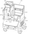
本発明は一般に、エクスビボ臓器ケアのためのシステム、方法および装置に関する。より詳しくは、各種態様において、本発明は、生理的または近生理的条件においてエクスビボで片肺または一対の肺をケアし、評価しかつそれに治療的対策を適用するための携帯型装置に関する。FIELD OF THEINVENTION The present invention relates generally to systems, methods and devices for ex vivo organ care. More particularly, in various aspects, the present invention relates to a portable device for caring for, assessing and applying therapeutic measures to a single or pair of lungs ex vivo under physiological or near-physiological conditions.
発明の背景
現行の臓器保存技術は、氷上の化学保存液中の臓器の低温貯蔵を典型的に包含する。これらの技術は種々の溶液を利用するが、そのいずれも、虚血によるダメージから臓器を十分に保護しない。臓器をドナーからレシピエントに移植することを意図する場合、そのような損傷は特に望ましくない。2. Background of the Invention Current organ preservation techniques typically involve the cold storage of organs in chemical preservation solutions on ice. These techniques utilize a variety of solutions, none of which adequately protect the organ from damage due to ischemia. Such damage is particularly undesirable when the organ is intended for transplantation from a donor to a recipient.
エクスビボ臓器の有効な生理的保存は、慣行的なアプローチに比較して重要な利益を与える可能性がある。例えば、生理的エクスビボ保存は、回収した臓器のより注意深いモニタリング、機能検査、評価および治療を可能にする可能性がある。これにより、回収した臓器の欠損のより早期の検出および潜在的修復を可能にして、移植後の臓器不全の可能性をさらに減少させる可能性がある。臓器に対する単純な修復を実行および評価する能力も、微小な欠損を有する多くの臓器を保存することを可能にする可能性がある一方で、現行の移植技術ではそれらを廃棄することが必要になる。肺を回収する場合にこのことは決定的に重要である。これは、ドナーの体内で回収する前であっても、肺は容易に損なわれるためである。Effective physiological preservation of ex vivo organs could provide important benefits compared to conventional approaches. For example, physiological ex vivo preservation could allow for more careful monitoring, functional testing, evaluation, and treatment of the retrieved organs. This could allow earlier detection and potential repair of defects in the retrieved organs, further reducing the chance of organ failure after transplantation. The ability to perform and evaluate simple repairs on organs could also allow for the preservation of many organs with minor defects, whereas current transplantation techniques require them to be discarded. This is critically important when retrieving lungs, as they are easily compromised even before retrieval in the donor's body.
さらに、臓器と特定のレシピエントとの間のより有効なマッチングを実現させて、最終的な臓器拒絶の可能性をさらに減少させることができる。現行の移植技術はドナーおよび受容体の血液型のマッチングに主に依存しているが、このマッチングはそれ自体、臓器をレシピエントが拒絶するか否かの指標としては比較的信頼性がない。臓器適合性のより好ましい試験はヒト白血球抗原(HLA)マッチング試験であるが、現行の冷虚血臓器保存アプローチは、完了に12時間以上をしばしば要することがあるこの試験の使用を妨げている。In addition, more effective matching between organs and specific recipients could be achieved, further reducing the chance of eventual organ rejection. Current transplantation techniques rely primarily on matching the blood types of the donor and recipient, which is, in itself, a relatively unreliable indicator of whether the organ will be rejected by the recipient. A more preferred test of organ compatibility is human leukocyte antigen (HLA) matching testing, but current cold ischemia organ preservation approaches preclude the use of this testing, which can often require 12 hours or more to complete.
慣行的なアプローチを使用する場合、虚血が引き起こす損傷は、臓器をエクスビボで維持する時間の長さの関数として増加する。例えば、典型的には、肺はわずか約6時間~約8時間しかエクスビボで保存できず、その後移植には使用不能になる。典型的には、心臓はわずか約4時間~約6時間しかエクスビボで保存できず、その後移植には使用不能になる。これらの比較的短い期間により、所与のドナー場所から到達可能なレシピエントの数が限定され、それにより、回収した臓器のためのレシピエントプールが制限される。期限内であっても、臓器はやはり著しくダメージを受けることがある。重大な問題は、ダメージの任意の観察可能な徴候がないことがあるということである。このため、最適未満の臓器を移植することで、移植後の臓器障害または他の損傷が生じることがある。したがって、エクスビボで健康状態で臓器を保存可能な時間を延長できる技術を開発することが望ましい可能性がある。そのような技術は移植後の臓器不全の危険性を減少させ、潜在的なドナーおよびレシピエントのプールを拡大する可能性がある。When using conventional approaches, the damage caused by ischemia increases as a function of the length of time that an organ is maintained ex vivo. For example, lungs can typically be stored ex vivo for only about 6 to about 8 hours before they are unusable for transplantation. Hearts can typically be stored ex vivo for only about 4 to about 6 hours before they are unusable for transplantation. These relatively short periods of time limit the number of recipients that can be reached from a given donor location, thereby restricting the recipient pool for retrieved organs. Even within the time frame, organs can still be significantly damaged. A significant problem is that there may not be any observable signs of damage. Thus, transplanting suboptimal organs can result in post-transplant organ failure or other damage. It may therefore be desirable to develop techniques that can extend the time that organs can be stored ex vivo in a healthy state. Such techniques could reduce the risk of post-transplant organ failure and expand the pool of potential donors and recipients.
長期のかつ信頼できるエクスビボ臓器ケアは、臓器移植の文脈外の利益を与える可能性もある。例えば、典型的には、患者の身体は全体として、多くの特定の臓器よりもはるかに低いレベルの化学療法、生物療法および放射線療法にしか耐容性を示さないことがある。エクスビボ臓器ケアシステムは、臓器を身体から取り出しかつ隔離下で処置することを可能にして、身体の他の部分に対するダメージの危険性を減少させる可能性がある。Long-term and reliable ex vivo organ care may also provide benefits outside the context of organ transplantation. For example, a patient's body as a whole may typically tolerate much lower levels of chemotherapy, biotherapy, and radiation therapy than many specific organs. Ex vivo organ care systems may allow organs to be removed from the body and treated in isolation, potentially reducing the risk of damage to the rest of the body.
上記に鑑み、エクスビボで臓器をケアするための改善されたシステム、方法および装置が求められている。In view of the above, there is a need for improved systems, methods and devices for caring for organs ex vivo.
本発明は、携帯型エクスビボ臓器ケアに関する改善されたシステム、方法、解決策および装置を各種態様において提供することで、当技術分野の現状における欠陥に対処する。The present invention addresses deficiencies in the current state of the art by providing improved systems, methods, solutions and devices for portable ex vivo organ care in various aspects.
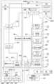
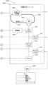
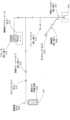
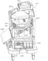
一般に、一局面では、本発明は携帯型シャーシを含む携帯型多用途モジュールと、単一用途使い捨てモジュールであって、多用途モジュールとの電気機械的相互操作のために単一用途使い捨てモジュールと多用途モジュールとを結合させるように適応したインターフェース; および、肺への灌流流体の流れを可能にするための第1のインターフェースと、換気ガスによる肺の換気を可能にするための第2のインターフェースと、肺から離れる灌流流体の流れを可能にするための第3のインターフェースとを有する肺チャンバアセンブリであって、肺から離れる灌流流体の流れを運搬するための二重ドレインシステムであって、灌流流体ガス含有量のセンサへ灌流流体流の一部を方向づけるための測定ドレインと、灌流流体流の残りの部分を受けるための主ドレインとを含む二重ドレインシステムを含む、肺チャンバアセンブリを含む、単一用途使い捨てモジュールとを含む、肺ケアシステムを特徴とする。一態様では、肺ケアシステムは、肺チャンバアセンブリから灌流流体を排出するためのドレナージシステムであって、ドレインシステムが測定導管および主ドレイン導管を含み、測定導管が灌流流体ガス含有量を測定するように適応したセンサへ灌流流体の流れをさらに方向づけるドレナージシステムを含む。In general, in one aspect, the invention features a lung care system including a portable multi-use module including a portable chassis; a single-use disposable module, the single-use disposable module having an interface adapted to couple the single-use disposable module and the multi-use module for electromechanical interoperability with the multi-use module; and a lung chamber assembly having a first interface for enabling a flow of perfusion fluid to the lung, a second interface for enabling ventilation of the lung with a ventilation gas, and a third interface for enabling a flow of perfusion fluid away from the lung, the lung chamber assembly including a dual drain system for conveying the flow of perfusion fluid away from the lung, the dual drain system including a measurement drain for directing a portion of the perfusion fluid flow to a sensor of perfusion fluid gas content and a main drain for receiving a remaining portion of the perfusion fluid flow. In one aspect, the lung care system includes a drainage system for draining the perfusion fluid from the lung chamber assembly, the drainage system including a measurement conduit and a main drain conduit, the measurement conduit further directing the flow of perfusion fluid to a sensor adapted to measure the perfusion fluid gas content.
他の態様は以下の特徴のうち1つまたは複数を含む。二重ドレインは灌流流体流を受け取るための容器を含み、容器からの溢流は主ドレインに流れる。システムは、灌流流体を循環させるためのポンプと、所定の組成を有するガスにより肺を換気するための換気システムとを含む。ガスは酸素、二酸化炭素を含む。携帯型多用途モジュールは使い捨てモジュールの電気制御、空気圧制御および機械制御のうち少なくとも1つを与えるための肺コンソールを含み、肺コンソールは、肺の換気を制御するための換気コントローラを含み、肺へのガスの流れを引き起こすベローズを作動させるための機械的アクチュエータを含む。肺コンソール空気圧制御システムは、使い捨てモジュールにおける肺に接続された換気ガス回路内の1つまたは複数のバルブを制御する。空気圧制御システムは、肺とベローズとの間の流れを遮るためのベローズバルブ、換気ガスを通気するためのリリーフバルブ、および換気ガス回路にガスを導入するためのトリクルバルブのうち少なくとも1つを制御する。換気コントローラは、酸素化ガス、脱酸素化ガスおよび維持ガスのうち1つより、肺の換気に使用するガスを選択する。酸素化ガスは空気、または25%~100%の酸素を含有するガスである。脱酸素化ガスは二酸化炭素および窒素で組成され、維持ガスは酸素、二酸化炭素および窒素で組成される。一態様では、脱酸素化ガスは約6%の二酸化炭素および約94%の窒素であり、維持ガスは約12%の酸素、約5.5%の二酸化炭素および約82.5%の窒素である。多用途モジュールは、灌流流体中の酸素などのガス含有量のレベルを制御可能な灌流流体コントローラを含む。灌流流体コントローラは、ガスの流れと灌流流体との間でガスを交換するガス交換器へのガスの流れを例えば制御することで、灌流流体ガス成分を制御する。ガス交換器に流れるガスは、灌流流体から酸素を除去する脱酸素化ガスである。多用途モニタは、肺ケアシステムのステータスを表示するためのモニタを含み、ステータスは、肺に入りかつ肺から出る灌流流体の酸素含有量に関する情報を含む。それは換気ガス圧および肺動脈圧のリアルタイム追跡も表示する。Other embodiments include one or more of the following features: The dual drain includes a container for receiving the perfusion fluid flow, with overflow from the container flowing to a main drain. The system includes a pump for circulating the perfusion fluid and a ventilation system for ventilating the lungs with a gas having a predetermined composition. The gas includes oxygen, carbon dioxide. The portable multi-use module includes a lung console for providing at least one of electrical, pneumatic and mechanical control of the disposable module, the lung console including a ventilation controller for controlling ventilation of the lungs and including a mechanical actuator for actuating a bellows causing the flow of gas to the lungs. The lung console pneumatic control system controls one or more valves in a ventilation gas circuit connected to the lungs in the disposable module. The pneumatic control system controls at least one of a bellows valve for blocking flow between the lungs and the bellows, a relief valve for venting the ventilation gas, and a trickle valve for introducing gas into the ventilation gas circuit. The ventilation controller selects a gas for ventilation of the lungs from one of an oxygenated gas, a deoxygenated gas and a maintenance gas. The oxygenated gas is air or a gas containing 25% to 100% oxygen. The deoxygenated gas is composed of carbon dioxide and nitrogen, and the maintenance gas is composed of oxygen, carbon dioxide, and nitrogen. In one embodiment, the deoxygenated gas is about 6% carbon dioxide and about 94% nitrogen, and the maintenance gas is about 12% oxygen, about 5.5% carbon dioxide, and about 82.5% nitrogen. The multi-purpose module includes a perfusion fluid controller capable of controlling the level of gas content, such as oxygen, in the perfusion fluid. The perfusion fluid controller controls the perfusion fluid gas composition, for example, by controlling the flow of gas to a gas exchanger that exchanges gas between the gas flow and the perfusion fluid. The gas flowing to the gas exchanger is a deoxygenated gas that removes oxygen from the perfusion fluid. The multi-purpose monitor includes a monitor for displaying the status of the pulmonary care system, including information regarding the oxygen content of the perfusion fluid entering and leaving the lungs. It also displays real-time tracking of ventilation gas pressure and pulmonary artery pressure.
一般に、別の局面では、本発明は単一用途使い捨てモジュールであって、多用途モジュールへの取り付けに適応したインターフェース、および肺への灌流流体の流れを可能にするための第1のインターフェースと、換気ガスによる肺の換気を可能にするための第2のインターフェースとを有する肺チャンバアセンブリを含む、単一用途使い捨てモジュールと; 肺チャンバアセンブリから灌流流体の流れを排出するためのドレインシステムであって、測定導管および主ドレイン導管を含み、測定導管が灌流流体ガス含有量を測定するように適応したセンサに対して灌流流体の流れをさらに方向づけるドレインシステムとを含む、肺ケアモジュールを特徴とする。In general, in another aspect, the invention features a lung care module including a single-use disposable module including a lung chamber assembly having an interface adapted for attachment to a multi-use module and a first interface for enabling flow of perfusion fluid to the lungs and a second interface for enabling ventilation of the lungs with a ventilation gas; and a drain system for draining the flow of perfusion fluid from the lung chamber assembly, the drain system including a measurement conduit and a main drain conduit, the measurement conduit further directing the flow of perfusion fluid to a sensor adapted to measure perfusion fluid gas content.
他の態様は以下の特徴のうち1つまたは複数を含む。モジュールは、維持ガス、評価ガス、および空気などの酸素化ガスのうち1つにより肺を換気するためのシステムを含む。システムは、ある量のガスを肺に再呼吸させるように構成され得る。換気システムは、約12%の酸素、約5.5%の二酸化炭素および約82.5%の窒素の組成を有する維持ガスにより肺を換気する。機械的に作動するベローズを使用して肺を換気する。換気システムは、維持ガスの流れを導入するためのトリクルバルブと、過剰のガスを通気するためのリリーフバルブとをさらに含む。肺に対する第2のインターフェースは、気管に挿入するための挿入部と、換気ガス回路に接続するためのコネクタ部とを有する気管カニューレを含む。肺に対する第1のインターフェースは、肺動脈に挿入するための挿入部と、灌流流体回路に接続するためのコネクタ部とを含む肺動脈カニューレを含む。それは、肺への灌流流体の流入地点の近くに圧力トランスデューサを位置づけるために、挿入管の近くにコネクタ部のルーメンへの開口を画定する圧力トランスデューサコネクタも含む。圧力トランスデューサコネクタは、圧力トランスデューサにおいて遠隔通気させるためのチャネルをさらに与える。Other aspects include one or more of the following features. The module includes a system for ventilating the lungs with one of a maintenance gas, an assessment gas, and an oxygenated gas, such as air. The system may be configured to rebreathe a volume of gas into the lungs. The ventilation system ventilates the lungs with a maintenance gas having a composition of about 12% oxygen, about 5.5% carbon dioxide, and about 82.5% nitrogen. The lungs are ventilated using a mechanically actuated bellows. The ventilation system further includes a trickle valve for introducing a flow of maintenance gas and a relief valve for venting excess gas. The second interface to the lungs includes a tracheal cannula having an insert portion for insertion into the trachea and a connector portion for connecting to a ventilation gas circuit. The first interface to the lungs includes a pulmonary artery cannula having an insert portion for insertion into the pulmonary artery and a connector portion for connecting to a perfusion fluid circuit. It also includes a pressure transducer connector defining an opening into the lumen of the connector portion near the insertion tube for positioning the pressure transducer near the point of entry of the perfusion fluid into the lungs. The pressure transducer connector further provides a channel for remote venting at the pressure transducer.
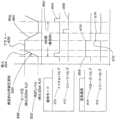
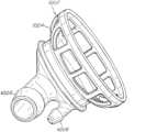
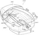
一般に、さらに別の局面では、本発明は少なくとも1つのハウジングドレインを含む底面、および壁面を有するハウジングと; 肺を支持するための支持面であって、肺から出る灌流流体を排出するためのドレイン、およびドレインに通じるドレナージチャネルを画定する支持面と; ハウジングの壁面への封止可能な接続を与える開閉式蓋と; 肺への灌流流体の流れを可能にするための第1のインターフェースと; 肺の換気を可能にするための第2のインターフェースと; 肺から離れる灌流流体の流れを可能にするための第3のインターフェースとを含む、肺チャンバアセンブリを特徴とする。In general, in yet another aspect, the invention features a lung chamber assembly including a housing having a bottom surface including at least one housing drain, and a wall surface; a support surface for supporting a lung, the support surface defining a drain for draining perfusion fluid from the lung, and a drainage channel leading to the drain; a retractable lid providing a sealable connection to the wall surface of the housing; a first interface for permitting flow of perfusion fluid to the lung; a second interface for permitting ventilation of the lung; and a third interface for permitting flow of perfusion fluid away from the lung.
他の態様は以下の特徴のうち1つまたは複数を含む。ハウジングは、肺から離れる灌流流体の流れを運搬するためのドレインシステムであって、灌流流体ガス含有量のセンサへ灌流流体流の一部を方向づけるための測定ドレインと、灌流流体流の残りの部分を受けるための主ドレインとを含むドレインシステムを含む。ドレインシステムは、肺から離れる灌流流体の流れを、測定ドレインに供給を行うプールに収集するための領域を有し、測定ドレインは、肺から離れる灌流流体の流量未満のドレナージ容量を有する。領域から溢流する灌流流体の流れは主ドレインに流れる。いくつかの態様では、ドレインシステムは、測定ドレインを部分的に取り囲む壁面であって、測定ドレインから主ドレインへの灌流流体の流れを部分的に遮断し、測定ドレインの上側での灌流流体のプールの形成を促進する壁面をさらに含む。肺チャンバのハウジングは、肺動脈カニューレ、肺動脈圧トランスデューサ導管および気管カニューレのハウジングを通じる封止された通路を与える開口を画定する。いくつかの態様では、灌流流体は、露出した左心房カフを通じて肺から出て、ドレナージシステムに流れる。他の態様では、肺から出る灌流流体の流れは、左心房カフへの封止された接続を通過し、左心房カフは、肺から離れる灌流流体を運搬する導管に接続されている。灌流流体流の一部は酸素含有量センサを通過し、残りはリザーバに流れる。Other aspects include one or more of the following features: The housing includes a drain system for conveying the flow of perfusion fluid away from the lungs, the drain system including a measurement drain for directing a portion of the perfusion fluid flow to a sensor of perfusion fluid gas content and a main drain for receiving the remaining portion of the perfusion fluid flow. The drain system has an area for collecting the flow of perfusion fluid away from the lungs in a pool that feeds the measurement drain, the measurement drain having a drainage capacity less than the flow rate of the perfusion fluid away from the lungs. The flow of perfusion fluid overflowing from the area flows to the main drain. In some aspects, the drain system further includes a wall partially surrounding the measurement drain that partially blocks the flow of perfusion fluid from the measurement drain to the main drain and promotes the formation of a pool of perfusion fluid above the measurement drain. The housing of the lung chamber defines an opening that provides a sealed passage through the housing of the pulmonary artery cannula, the pulmonary artery pressure transducer conduit, and the tracheal cannula. In some embodiments, the perfusion fluid leaves the lungs through an exposed left atrial cuff and flows to a drainage system. In other embodiments, the flow of perfusion fluid leaving the lungs passes through a sealed connection to the left atrial cuff, which is connected to a conduit that carries the perfusion fluid away from the lungs. A portion of the perfusion fluid flow passes through an oxygen content sensor and the remainder flows to a reservoir.
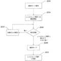
一般に、さらなる局面では、本発明はエクスビボ灌流回路内に肺を位置づける段階; 肺動脈インターフェースを通じて肺に入りかつ左心房インターフェースを通じて肺を離れる灌流流体を肺に循環させる段階; 気管インターフェースを通じて換気ガスを流すことで肺を換気する段階; 灌流流体中の酸素含有量の所定の第1の値に到達するまで灌流流体を脱酸素化する段階; 灌流流体中の酸素含有量の所定の第2の値に到達するまで酸素化ガスにより肺を換気することで灌流流体を再酸素化する段階; および灌流流体中の酸素含有量レベルを酸素含有量の第1の値から酸素含有量の第2の値に変化させるために肺が要する時間に基づいて肺の状態を判断する段階を含む、肺を診断する方法を特徴とする。In general, in a further aspect, the invention features a method of diagnosing a lung, the method including positioning a lung in an ex vivo perfusion circuit; circulating perfusion fluid to the lung that enters the lung through a pulmonary artery interface and leaves the lung through a left atrial interface; ventilating the lung by flowing a ventilation gas through a tracheal interface; deoxygenating the perfusion fluid until a first predetermined value of oxygen content in the perfusion fluid is reached; reoxygenating the perfusion fluid by ventilating the lung with an oxygenated gas until a second predetermined value of oxygen content in the perfusion fluid is reached; and determining a condition of the lung based on a time it takes the lung to change a level of oxygen content in the perfusion fluid from the first oxygen content value to the second oxygen content value.
他の態様は以下の特徴のうち1つまたは複数を含む。灌流流体は、二酸化炭素および窒素、例えば約5.5%の二酸化炭素および約94.5%の窒素を含む換気ガスにより肺を換気することで脱酸素化される。灌流流体は、ガス交換装置に灌流流体を循環させることで脱酸素化され、ガス交換装置は、二酸化炭素および窒素を含む脱酸素化ガスと流体連通しており、ガス交換装置は、換気ガスと灌流流体との間のガス交換により灌流流体中の酸素の組成を改変する。酸素含有量の所定の第1の値は約73%の赤血球飽和度に対応する。酸素化ガスは空気、または約25%~約100%の酸素を含むガスである。酸素含有量の所定の第2の値は約93%の赤血球飽和度に対応する。灌流流体は、1分当たり約1.5リットルの速度で流れ、ヒーターで近生理的温度レベルに加温される。灌流流体は全血、または、白血球が部分的に枯渇しているかもしくは血小板が部分的に枯渇している血液などの血液製剤で組成される。各種治療薬は、灌流中に灌流流体を経由して、または、気管インターフェースを通じて噴霧器もしくは気管支鏡を使用して、肺に送達される。灌流流体中の酸素レベルは、流体中の赤血球飽和度を決定するパルスオキシメーターを使用して測定される。Other embodiments include one or more of the following features: The perfusion fluid is deoxygenated by ventilating the lungs with a ventilation gas comprising carbon dioxide and nitrogen, e.g., about 5.5% carbon dioxide and about 94.5% nitrogen. The perfusion fluid is deoxygenated by circulating the perfusion fluid through a gas exchange device in fluid communication with a deoxygenated gas comprising carbon dioxide and nitrogen, the gas exchange device modifying the composition of oxygen in the perfusion fluid by gas exchange between the ventilation gas and the perfusion fluid. The first predetermined value of oxygen content corresponds to a red blood cell saturation of about 73%. The oxygenating gas is air or a gas comprising about 25% to about 100% oxygen. The second predetermined value of oxygen content corresponds to a red blood cell saturation of about 93%. The perfusion fluid flows at a rate of about 1.5 liters per minute and is warmed to a near-physiological temperature level by a heater. The perfusion fluid is composed of whole blood or a blood product such as blood that is partially depleted of white blood cells or partially depleted of platelets. Various therapeutic agents are delivered to the lungs via the perfusion fluid during perfusion, or through the tracheal interface using a nebulizer or bronchoscope. Oxygen levels in the perfusion fluid are measured using a pulse oximeter, which determines red blood cell saturation in the fluid.
一般に、さらなる局面では、本発明は肺動脈インターフェースを通じて肺に入りかつ左心房インターフェースを通じて肺を離れる灌流流体を肺に循環させる段階; 肺と可変量チャンバとの間で捕集量(captive volume)の換気ガスを行ったり来たり流すことで気管インターフェースを通じて肺を換気する段階; およびさらなる量の換気ガスを捕集量に導入しかつ捕集量から過剰の換気ガスを通気させることで、換気ガスの所定の組成を維持しかつ捕集量の最小ガス圧を維持する段階を含む、エクスビボで肺を保存する方法を特徴とする。In general, in a further aspect, the invention features a method of preserving a lung ex vivo, including circulating to the lung perfusion fluid entering the lung through a pulmonary artery interface and leaving the lung through a left atrial interface; ventilating the lung through a tracheal interface by flowing a captive volume of ventilation gas back and forth between the lung and a variable volume chamber; and introducing an additional amount of ventilation gas into the captive volume and venting excess ventilation gas from the captive volume to maintain a predetermined composition of ventilation gas and maintain a minimum gas pressure in the captive volume.
他の態様は以下の特徴のうち1つまたは複数を含む。換気ガスは酸素、二酸化炭素、および窒素などの不活性ガスの組成を含む。灌流流体は、換気ガスの所定の組成に対応する平衡レベルに到達する。換気ガスの所定の組成は約5~20%の酸素および約2~10%の二酸化炭素を含む。灌流流体のガス含有量は、約88%~98%のヘモグロビン飽和度レベルを有する平衡レベルに到達する。Other embodiments include one or more of the following features: The ventilation gas includes a composition of oxygen, carbon dioxide, and an inert gas, such as nitrogen. The perfusion fluid reaches an equilibrium level corresponding to a predetermined composition of the ventilation gas. The predetermined composition of the ventilation gas includes about 5-20% oxygen and about 2-10% carbon dioxide. The gas content of the perfusion fluid reaches an equilibrium level having a hemoglobin saturation level of about 88%-98%.
換気ガスの所定の組成は約12%の酸素および約5.5%の二酸化炭素を含む。肺に入る灌流流体のヘモグロビン飽和度レベルは約90~95%の平衡レベルに到達し、肺を離れる灌流流体のヘモグロビン飽和度レベルは約90~95%の平衡レベルに到達する。肺に入る灌流流体の酸素含有量は生理的レベルよりも低く、肺を離れる灌流流体の酸素含有量は生理的レベルよりも高い。以下のパラメータがある種の態様において使用される: 換気ガスのさらなる流れは1分当たり約400~600mLであり、捕集量は約400~1200mLであり、捕集量の最小ガス圧はH2O約4~8cmであり、換気ガスの最大圧力はH2O約12~22cmである。過剰の換気ガスは、捕集量と連通するリリーフバルブを通じて通気される。可変量チャンバはベローズであり、ベローズを圧縮することは肺への換気ガスの流れを引き起こす。肺動脈インターフェースは肺動脈カニューレを含み、肺動脈カニューレの一部は肺の肺動脈に挿入される。灌流流体は、肺の露出した左心房カフを通じて、または左心房カフと左心房カニューレとの間の封止または半封止された接続を通じて、肺から離れるよう流れる。気管インターフェースは気管カニューレを含み、気管カニューレの一部は肺の気管に挿入される。本方法は、肺に流れる灌流流体中の酸素含有量の第1のレベルおよび肺から流れる灌流流体中の酸素含有量の第2のレベルを測定する段階を含む。酸素測定段階は、灌流流体中のヘモグロビンの酸素飽和度のレベル、および肺に流れかつ肺から流れる灌流流体中の酸素の分圧のうち少なくとも1つを測定する段階を含む。灌流流体は血液製剤を含み、治療薬を肺に送達することができる。換気ガスと灌流流体との間の肺内でのガス交換は、灌流流体中の酸素および二酸化炭素などの1つまたは複数のガスのレベルを平衡値に到達させる。肺は、平衡レベルのガスにより維持する場合、約3~24時間保存することができる。
[本発明1001]
携帯型シャーシを含む携帯型多用途モジュールと;
多用途モジュールとの電気機械的相互操作のために単一用途使い捨てモジュールと多用途モジュールとを結合させるように適応したインターフェース; および
肺への灌流流体の流れを可能にするための第1のインターフェースと、換気ガスによる肺の換気を可能にするための第2のインターフェースと、肺から離れる灌流流体の流れを可能にするための第3のインターフェースとを有する肺チャンバアセンブリであって、灌流流体流の一部を灌流流体ガス含有量のセンサへ方向づけるための測定ドレインと、灌流流体流の残りの部分を受け取るための主ドレインとを含む、肺から離れる灌流流体の流れを運搬するための二重ドレインシステムを含む肺チャンバアセンブリを含む、
単一用途使い捨てモジュールと
を含む、肺ケアシステム。
[本発明1002]
二重ドレインが、肺から離れる灌流流体の流れを、測定ドレインに供給するプールに収集するための容器をさらに含み、該測定ドレインのドレナージ容量が肺から離れる灌流流体の流量未満であり、容器から溢流する過剰の灌流流体が主ドレインに流れる、本発明1001のシステム。
[本発明1003]
使い捨てモジュールが、灌流流体を肺に循環させるように適応したポンプをさらに含む、本発明1001のシステム。
[本発明1004]
所定の組成を有するガスにより肺を換気するための、第2のインターフェースに接続された換気システムをさらに含む、本発明1001のシステム。
[本発明1005]
所定の組成が約12%の酸素を含む、本発明1004のシステム。
[本発明1006]
所定の組成が約12%の酸素、約5.5%の二酸化炭素および約82.5%の窒素である、本発明1004のシステム。
[本発明1007]
主ドレインと灌流流体用リザーバとの間の流体連通を与える導管をさらに含む、本発明1001のシステム。
[本発明1008]
携帯型多用途モジュールが、使い捨てモジュールの電気制御、空気圧制御および機械制御のうち少なくとも1つを与えるための肺コンソールを含む、本発明1001のシステム。
[本発明1009]
肺コンソールが、肺の換気を制御するための換気コントローラを含む、本発明1008のシステム。
[本発明1010]
換気コントローラが、肺への換気ガスの流れを引き起こすためのベローズを作動させるための機械的アクチュエータを含む、本発明1009のシステム。
[本発明1011]
肺コンソールモジュールが、使い捨てモジュールにおける、肺に接続された換気ガス回路内の少なくとも1つのバルブを制御するための空気圧制御システムを含む、本発明1009のシステム。
[本発明1012]
少なくとも1つのバルブが、肺とベローズとの間の換気ガス回路、すなわち肺とベローズとの間のガス接続を閉鎖するバルブのオフ位置に配設されている、本発明1011のシステム。
[本発明1013]
少なくとも1つのバルブが、肺換気回路から換気ガスを通気させるためのリリーフバルブを含む、本発明1011のシステム。
[本発明1014]
少なくとも1つのバルブが、換気ガス回路に換気ガスを導入するためのトリクルバルブを含む、本発明1011のシステム。
[本発明1015]
換気コントローラが、肺を換気するための複数のガスのうち1つを選択可能である、本発明1009のシステム。
[本発明1016]
複数のガスが、酸素化ガス、脱酸素化ガスおよび維持ガスを含む、本発明1015のシステム。
[本発明1017]
酸素化ガスが、空気、および25%~100%の酸素を含有するガスからなるセットより選択される、本発明1016のシステム。
[本発明1018]
脱酸素化ガスが、二酸化炭素および窒素を含む、本発明1016のシステム。
[本発明1019]
脱酸素化ガスが、約6%の二酸化炭素および約94%の窒素で組成される、本発明1016のシステム。
[本発明1020]
維持ガスが、酸素、二酸化炭素および窒素を含む、本発明1016のシステム。
[本発明1021]
維持ガスが、約12%の酸素、約5.5%の二酸化炭素および約82.5%の窒素で組成される、本発明1016のシステム。
[本発明1022]
維持ガスが、多用途モジュール内に収納されたタンクから供給される、本発明1016のシステム。
[本発明1023]
携帯型多用途モジュールが、灌流流体ガス成分を制御するための灌流流体コントローラを含む、本発明1008のシステム。
[本発明1024]
灌流流体コントローラが、使い捨てモジュール内のガス交換器へのガスの流れを制御するための空気圧バルブコントローラを含み、該ガス交換器が、該ガス交換器へのガスの流れと灌流流体との間でガスを交換するように構成されている、本発明1023のシステム。
[本発明1025]
ガス交換器へのガスの流れが、灌流流体から酸素を除去するための脱酸素化ガスを含む、本発明1024のシステム。
[本発明1026]
脱酸素化ガスが、二酸化炭素および窒素を含む、本発明1025のシステム。
[本発明1027]
脱酸素化ガスが、約6%の二酸化炭素および約94%の窒素で組成される、本発明1025のシステム。
[本発明1028]
多用途モジュールが、肺ケアシステムのステータスを表示するためのモニタと、肺ケアシステムの操作を制御するためのユーザーインターフェースとを含む、本発明1001のシステム。
[本発明1029]
表示されるステータスが、肺に入る灌流流体の酸素含有量および肺から出る灌流流体の酸素含有量のうち少なくとも1つを含む、本発明1028のシステム。
[本発明1030]
モニタが、ガスが肺に入る地点の換気ガス圧のリアルタイム追跡、灌流流体が肺動脈に入る地点に位置する圧力センサにより測定される肺の肺動脈圧のリアルタイム追跡、および肺動脈圧の時間平均グラフを表示する、本発明1028のシステム。
[本発明1031]
多用途モジュールが、肺の評価中に肺ケアシステムのステータスを表示するためのモニタと、肺ケアシステムの操作を制御するためのユーザーインターフェースとを含み、該モニタが、肺に入る灌流流体の酸素含有量のリアルタイム追跡および肺を離れる灌流流体の酸素含有量のリアルタイム追跡を表示する、本発明1001のシステム。
[本発明1032]
携帯型シャーシおよび肺コンソールを含む携帯型多用途モジュールと;
多用途モジュールとの電気機械的相互操作のために単一用途使い捨てモジュールと多用途モジュールとを結合させるように適応したインターフェース; および
肺への灌流流体の流れを可能にするための第1のインターフェースと、換気ガスによる肺の換気を可能にするための第2のインターフェースと、肺から離れる灌流流体の流れを可能にするための第3のインターフェースとを有する肺チャンバアセンブリを含む、
単一用途使い捨てモジュールとを含み、
該肺コンソールが、該使い捨てモジュールの灌流流体および換気ガスの、電気制御、空気圧制御および機械制御のうち少なくとも1つを与える、
肺ケアシステム。
[本発明1033]
肺チャンバアセンブリが、肺から離れる灌流流体の流れを運搬するための二重ドレインシステムであって、灌流流体流の一部を灌流流体ガス含有量のセンサへ方向づけるための測定ドレインと、灌流流体流の残りの部分を受けるための主ドレインとを含む二重ドレインシステムを含む、本発明1032のシステム。
[本発明1034]
二重ドレインが、肺から離れる灌流流体の流れを、測定ドレインに供給を行うプールに収集するための容器をさらに含み、該測定ドレインのドレナージ容量が肺から離れる灌流流体の流量未満であり、容器から溢流する過剰の灌流流体が主ドレインに流れる、本発明1033のシステム。
[本発明1035]
使い捨てモジュールが、灌流流体を肺に循環させるように適応したポンプをさらに含む、本発明1032のシステム。
[本発明1036]
使い捨てモジュールが、所定の組成を有するガスにより肺を換気するための、第2のインターフェースに接続された換気システムをさらに含む、本発明1032のシステム。
[本発明1037]
所定の組成が、約12%の酸素を含む、本発明1036のシステム。
[本発明1038]
所定の組成が、約12%の酸素、約5.5%の二酸化炭素および約82.5%の窒素である、本発明1036のシステム。
[本発明1039]
主ドレインが、灌流流体の残りの部分をリザーバへ方向づける、本発明1033のシステム。
[本発明1040]
肺コンソールが、肺の換気を制御するための換気コントローラを含む、本発明1032のシステム。
[本発明1041]
換気コントローラが、肺への換気ガスの流れを引き起こすためのベローズを作動させるための機械的アクチュエータを含む、本発明1040のシステム。
[本発明1042]
肺コンソールモジュールが、使い捨てモジュールにおける、肺に接続された換気ガス回路内の少なくとも1つのバルブを制御するための空気圧制御システムを含む、本発明1040のシステム。
[本発明1043]
少なくとも1つのバルブが、肺とベローズとの間の換気ガス回路、すなわち肺とベローズとの間の流体接続を閉鎖するバルブのオフ位置に配設されている、本発明1042のシステム。
[本発明1044]
少なくとも1つのバルブが、肺換気回路から換気ガスを通気させるためのリリーフバルブを含む、本発明1042のシステム。
[本発明1045]
少なくとも1つのバルブが、換気ガス回路に換気ガスを送達するためのトリクルバルブを含む、本発明1042のシステム。
[本発明1046]
換気コントローラが、肺を換気するための複数のガスのうち1つを選択するように構成されている、本発明1040のシステム。
[本発明1047]
複数のガスが、酸素化ガス、脱酸素化ガスおよび維持ガスを含む、本発明1046のシステム。
[本発明1048]
酸素化ガスが、空気、および25%~100%の酸素を含有するガスからなるセットより選択される、本発明1047のシステム。
[本発明1049]
脱酸素化ガスが、二酸化炭素および窒素を含む、本発明1047のシステム。
[本発明1050]
脱酸素化ガスが、約6%の二酸化炭素および約94%の窒素で組成される、本発明1047のシステム。
[本発明1051]
維持ガスが、酸素、二酸化炭素および窒素を含む、本発明1047のシステム。
[本発明1052]
維持ガスが、約12%の酸素、約5.5%の二酸化炭素および約82.5%の窒素で組成される、本発明1047のシステム。
[本発明1053]
維持ガスが、多用途モジュール内に収納されたタンクから供給される、本発明1047のシステム。
[本発明1054]
肺コンソールが、灌流流体ガス成分を制御するための灌流流体コントローラを含む、本発明1032のシステム。
[本発明1055]
灌流流体コントローラが、使い捨てモジュール内のガス交換器へのガスの流れを制御するための空気圧バルブコントローラを含み、該ガス交換器が、該ガス交換器へのガスの流れと灌流流体との間でガスを交換するように構成されている、本発明1054のシステム。
[本発明1056]
ガス交換器へのガスの流れが、灌流流体から酸素を除去するための脱酸素化ガスを含む、本発明1055のシステム。
[本発明1057]
脱酸素化ガスが、二酸化炭素および窒素を含む、本発明1056のシステム。
[本発明1058]
脱酸素化ガスが、約6%の二酸化炭素および約94%の窒素で組成される、本発明1056のシステム。
[本発明1059]
多用途モジュールが、肺ケアシステムのステータスを表示するためのモニタと、肺ケアシステムの操作を制御するためのユーザーインターフェースとを含む、本発明1032のシステム。
[本発明1060]
表示されるステータスが、肺に入る灌流流体の酸素含有量および肺から出る灌流流体の酸素含有量のうち少なくとも1つを含む、本発明1059のシステム。
[本発明1061]
モニタが、ガスが肺に入る地点の換気ガス圧のリアルタイム追跡、灌流流体が肺動脈に入る地点に位置する圧力センサにより測定される肺の肺動脈圧のリアルタイム追跡、および肺動脈圧の時間平均グラフを表示する、本発明1059のシステム。
[本発明1062]
多用途モジュールが、肺の評価中に肺ケアシステムのステータスを表示するためのモニタと、肺ケアシステムの操作を制御するためのユーザーインターフェースとを含み、該モニタが、肺に入る灌流流体の酸素含有量のリアルタイム追跡および肺を離れる灌流流体の酸素含有量のリアルタイム追跡を表示する、本発明1032のシステム。
[本発明1063]
シャーシを含む多用途モジュールと;
多用途モジュールへの取り付けに適応したインターフェース;
肺への灌流流体の流れを可能にするための第1のインターフェースと、換気ガスによる肺の換気を可能にするための第2のインターフェースと、肺から離れる灌流流体の流れを可能にするための第3のインターフェースとを有する肺チャンバアセンブリ; ならびに
肺チャンバアセンブリから灌流流体を排出するためのドレインシステムであって、測定導管および主ドレイン導管を含み、該測定導管が灌流流体ガス含有量を測定するように適応したセンサへ灌流流体の流れをさらに方向づけるドレインシステムを含む、
単一用途使い捨てモジュールと
を含む、肺ケアシステム。
[本発明1064]
測定導管が、センサによるガス含有量測定に好適な条件に灌流流体を配置するように適応している、本発明1063のシステム。
[本発明1065]
灌流流体ガス含有量が酸素含有量である、本発明1063のシステム。
[本発明1066]
センサがパルスオキシメータである、本発明1063のシステム。
[本発明1067]
多用途モジュールへの取り付けに適応したインターフェース、および
肺への灌流流体の流れを可能にするための第1のインターフェースと、換気ガスによる肺の換気を可能にするための第2のインターフェースとを有する肺チャンバアセンブリを含む、
単一用途使い捨てモジュールと;
肺チャンバアセンブリから灌流流体の流れを排出するためのドレインシステムであって、測定導管および主ドレイン導管を含み、該測定導管が灌流流体ガス含有量を測定するように適応したセンサへ灌流流体の流れをさらに方向づけるドレインシステムと
を含む、肺ケアモジュール。
[本発明1068]
ガスにより肺を換気するための、第2のインターフェースに接続された換気システムをさらに含む、本発明1067のモジュール。
[本発明1069]
ガスが各々所定の組成を有する複数のガスより選択可能である、本発明1068のモジュール。
[本発明1070]
複数のガスが、維持ガス、評価ガスおよび空気を含む、本発明1069のモジュール。
[本発明1071]
維持ガスの所定の組成が、約12%の酸素を含む、本発明1070のモジュール。
[本発明1072]
維持ガスの所定の組成が、約12%の酸素、約5.5%の二酸化炭素および約82.5%の窒素である、本発明1070のモジュール。
[本発明1073]
換気システムが、ある量の維持ガスを肺に再呼吸させるように構成され得る、本発明1068のモジュール。
[本発明1074]
換気システムが隔離量区画を含み、かつ前記量の維持ガスが肺と隔離量区画との間でサイクルされる、本発明1073のモジュール。
[本発明1075]
換気システムがベローズを含み、かつ該ベローズを作動させることで前記量の維持ガスが肺とベローズとの間でサイクルされる、本発明1073のモジュール。
[本発明1076]
換気システムが、トリクルバルブを経由する維持ガスの外部供給源への接続を含み、該トリクルバルブが、換気システム内にガスを放出することで換気システム内の維持ガスの所定の組成を維持する、本発明1073のモジュール。
[本発明1077]
換気システムが、肺中の最小ガス圧を維持するリリーフバルブをさらに含む、本発明1068のモジュール。
[本発明1078]
評価ガスの所定の組成が、約6%の二酸化炭素を含む、本発明1070のモジュール。
[本発明1079]
評価ガスの所定の組成が、約4~7%の二酸化炭素および約93~97%の窒素を含む、本発明1070のモジュール。
[本発明1080]
第2のインターフェースが気管カニューレを含む、本発明1067のモジュール。
[本発明1081]
気管カニューレが、気管に挿入するための気管挿入部と、可撓部と、肺チャンバアセンブリに気管カニューレを固定するためのロック機構と、換気装置コネクタ部とを含む、本発明1080のモジュール。
[本発明1082]
気管挿入部が約0.65インチ~0.95インチの直径を有する、本発明1081のモジュール。
[本発明1083]
可撓部をクランプすることで、肺へのおよび肺からのガス流を封鎖することができる、本発明1081のモジュール。
[本発明1084]
灌流流体を肺へおよび肺から離れるよう流すように適応したポンプをさらに含む、本発明1067のモジュール。
[本発明1085]
灌流流体の温度を生理的レベル近くに維持するために灌流流体と熱接触するヒーターをさらに含む、本発明1084のモジュール。
[本発明1086]
前記温度が約30℃~37℃である、本発明1085のモジュール。
[本発明1087]
前記温度が約34℃~37℃である、本発明1085のモジュール。
[本発明1088]
少なくとも1つのガス供給源および灌流流体と流体連通するガス交換装置であって、灌流流体中の第1のガス成分の組成を制御可能に調節するように適応したガス交換装置をさらに含む、本発明1084のモジュール。
[本発明1089]
灌流流体中のガス成分の組成を調節するために複数のガス供給源より選択するためのガス選択スイッチをさらに含む、本発明1088のモジュール。
[本発明1090]
第1のインターフェースが肺動脈カニューレを含む、本発明1084のモジュール。
[本発明1091]
肺動脈カニューレが、肺動脈への挿入のための挿入管と、挿入管に接続したコネクタ部と、肺への灌流流体の流れを運搬する回路への接続のためにコネクタ部に接続した主管部とを含む、本発明1090のモジュール。
[本発明1092]
肺動脈カニューレが、肺への灌流流体の流入地点の近くに圧力トランスデューサを位置づけるために、挿入管の近くにコネクタ部のルーメンへの開口を画定する圧力トランスデューサコネクタをさらに含む、本発明1091のモジュール。
[本発明1093]
圧力トランスデューサコネクタが、圧力トランスデューサが遠隔通気されるように、チャネルをさらに与える、本発明1092のモジュール。
[本発明1094]
肺動脈カニューレが2つの挿入管を含む、本発明1092のモジュール。
[本発明1095]
挿入管が、肺動脈カニューレの主軸から約15°~90°の角度で隔てられている、本発明1092のモジュール。
[本発明1096]
灌流流体が肺からドレインシステムに流れることを可能にするために、肺の左心房カフが肺チャンバアセンブリに露出される、本発明1067のモジュール。
[本発明1097]
使い捨てモジュールが、左心房カフと、肺からドレインシステムへ灌流流体を方向づけるカニューレとの間の接続をさらに含む、本発明1067のモジュール。
[本発明1098]
肺チャンバアセンブリが、ハウジング、支持面および開閉式蓋を含む、本発明1067のモジュール。
[本発明1099]
前記支持面が、肺から流れる灌流流体を排出するためのドレインおよびドレナージチャネルを画定する、本発明1098のモジュール。
[本発明1100]
前記支持面が、肺に支持を供しかつ肺をアンカーするために可撓ラップを固定するように構成されている、本発明1098のモジュール。
[本発明1101]
可撓ラップがポリウレタンを含む、本発明1098のモジュール。
[本発明1102]
少なくとも1つのハウジングドレインを含む底面、および壁面を有するハウジングと;
肺を支持するための支持面であって、肺から出る灌流流体を排出するためのドレイン、およびドレインに通じるドレナージチャネルを画定する支持面と;
ハウジングの壁面への封止可能な接続を与える開閉式蓋と;
肺への灌流流体の流れを可能にするための第1のインターフェースと;
肺の換気を可能にするための第2のインターフェースと;
肺から離れる灌流流体の流れを可能にするための第3のインターフェースと
を含む、肺チャンバアセンブリ。
[本発明1103]
ハウジングが、肺から離れる灌流流体の流れを運搬するためのドレインシステムであって、灌流流体流の一部を灌流流体ガス含有量のセンサへ方向づけるための測定ドレインと、灌流流体流の残りの部分を受けるための主ドレインとを含むドレインシステムを含む、本発明1102のアセンブリ。
[本発明1104]
ドレインシステムが、肺から離れる灌流流体の流れを、測定ドレインに供給するプールに収集するための領域をさらに含み、該測定ドレインが、肺から離れる灌流流体の流量未満のドレナージ容量を有する、本発明1103のアセンブリ。
[本発明1105]
前記領域から溢流する灌流流体の流れが主ドレインに流れる、本発明1104のアセンブリ。
[本発明1106]
ドレインシステムが、測定ドレインを部分的に取り囲む壁面であって、測定ドレインから主ドレインへの灌流流体の流れを部分的に遮断し、測定ドレインの上側での灌流流体のプールの形成を促進する壁面をさらに含む、本発明1103のアセンブリ。
[本発明1107]
第1のインターフェースが肺動脈カニューレを含み、該カニューレの近位部が灌流流体回路に接続され、かつ該カニューレの遠位部が肺の肺動脈に接続される、本発明1102のアセンブリ。
[本発明1108]
ハウジングの壁面が、肺カニューレの外面をハウジングに封止可能に係合するための開口を画定する、本発明1107のアセンブリ。
[本発明1109]
肺動脈カニューレが、該カニューレの遠位端の近くに該カニューレのルーメンへの開口を画定する圧力トランスデューサコネクタをさらに含む、本発明1107のアセンブリ。
[本発明1110]
圧力トランスデューサコネクタが、カニューレ内の圧力トランスデューサが遠隔通気されるように、チャネルを与える、本発明1109のアセンブリ。
[本発明1111]
肺動脈への灌流流体の流入地点の近くに位置づけられる圧力トランスデューサであって、圧力トランスデューサコネクタおよび圧力トランスデューサ導管を通過する圧力トランスデューサケーブルにより外部コントローラに接続される圧力トランスデューサをさらに含む、本発明1109のアセンブリ。
[本発明1112]
ハウジングの壁面が、圧力トランスデューサ導管の外面を封止可能に係合するための開口を画定する、本発明1111のアセンブリ。
[本発明1113]
第2のインターフェースが、気管への挿入のための遠位挿入部と、肺を換気するためにガス回路に接続するための近位コネクタ部と、コネクタ部に隣接するロック機構とを有する気管カニューレを含む、本発明1102のアセンブリ。
[本発明1114]
ハウジングの壁面が、気管カニューレロック機構をハウジングに封止可能に係合するための開口を画定する、本発明1113のアセンブリ。
[本発明1115]
気管挿入部が、約0.65インチ~0.95インチの直径を有する、本発明1113のアセンブリ。
[本発明1116]
挿入部が、遠位端および近位端において、挿入部の直径より約0.2大きい直径を有するリブに接している、本発明1113のアセンブリ。
[本発明1117]
第3のインターフェースが、灌流流体が肺から支持面ドレインに流れることを可能にするために肺チャンバアセンブリに露出される左心房カフを含む、本発明1102のアセンブリ。
[本発明1118]
第3のインターフェースが、左心房カフとカニューレとの間の接続を含む、本発明1102のアセンブリ。
[本発明1119]
カニューレが、灌流流体を灌流ガス含有量センサへおよびリザーバへ方向づける導管と流体連通している、本発明1118のアセンブリ。
[本発明1120]
カニューレが、灌流流体を支持面ドレインへ方向づける、本発明1118のアセンブリ。
[本発明1121]
カニューレが、カニューレと左心房カフとの間の小さい接触面積を実現するためのケージ状構造を有する、本発明1118のアセンブリ。
[本発明1122]
カニューレが、左心房カフを開放状に保持するように構成されている、本発明1017のアセンブリ。
[本発明1123]
カニューレが、カニューレ内に位置づけられる圧力トランスデューサに接続するためのルーメンおよびコネクタをさらに含む、本発明1017のアセンブリ。
[本発明1124]
肺動脈インターフェースを通じて肺に入りかつ左心房インターフェースを通じて肺を離れる灌流流体を肺に循環させる段階;
肺と可変量チャンバとの間で捕集量(captive volume)の換気ガスを行ったり来たり流すことで気管インターフェースを通じて肺を換気する段階; および
換気ガスのさらなる流れを捕集量に導入しかつ捕集量から過剰の換気ガスを通気させることで、換気ガスの所定の組成を維持しかつ捕集量の最小ガス圧を維持する段階
を含む、エクスビボで肺を保存する方法。
[本発明1125]
換気ガスが、酸素、二酸化炭素および不活性ガスの組成物を含む、本発明1124の方法。
[本発明1126]
不活性ガスが窒素である、本発明1125の方法。
[本発明1127]
灌流流体のガス含有量が、換気ガスの所定の組成に対応する平衡レベルに到達する、本発明1124の方法。
[本発明1128]
換気ガスの所定の組成が、約5~20%の酸素および約2~10%の二酸化炭素を含む、本発明1124の方法。
[本発明1129]
灌流流体のガス含有量が、約88%~98%のヘモグロビン飽和度レベルを有する平衡レベルに到達する、本発明1128の方法。
[本発明1130]
換気ガスの所定の組成が、約12%の酸素および約5.5%の二酸化炭素を含む、本発明1124の方法。
[本発明1131]
肺に入る灌流流体のヘモグロビン飽和度レベルが約90~95%の平衡レベルに到達し、かつ肺を離れる灌流流体のヘモグロビン飽和度レベルが約90~95%の平衡レベルに到達する、本発明1127の方法。
[本発明1132]
肺に入る灌流流体の酸素含有量が生理的レベルよりも低く、かつ肺を離れる灌流流体の酸素含有量が生理的レベルよりも高い、本発明1124の方法。
[本発明1133]
換気ガスのさらなる流れが1分当たり約400~600mLである、本発明1124の方法。
[本発明1134]
捕集量が約400~1200mLである、本発明1124の方法。
[本発明1135]
捕集量の最小ガス圧が、H2O約4~8cmである、本発明1124の方法。
[本発明1136]
換気ガスの最大圧が、H2O約12~22cmである、本発明1124の方法。
[本発明1137]
過剰の換気ガスが、捕集量と連通するリリーフバルブを通じて通気される、本発明1124の方法。
[本発明1138]
可変量チャンバがベローズを含む、本発明1124の方法。
[本発明1139]
ベローズを圧縮することで肺への換気ガスの流れを引き起こす段階をさらに含む、本発明1138の方法。
[本発明1140]
ベローズと肺との間を流れる換気ガスの量が、ベローズの圧縮ストロークの大きさにより決定される、本発明1139の方法。
[本発明1141]
肺からの換気ガスの流れが肺の収縮により引き起こされる、本発明1124の方法。
[本発明1142]
肺動脈インターフェースが肺動脈カニューレを含み、該肺動脈カニューレの一部が肺の肺動脈に挿入される、本発明1124の方法。
[本発明1143]
灌流流体が、露出した左心房カフを通じて肺から離れるよう流れる、本発明1124の方法。
[本発明1144]
左心房インターフェースが肺の左心房と左心房カニューレとの間の封止された接続を含む、本発明1124の方法。
[本発明1145]
気管インターフェースが気管カニューレを含み、該気管カニューレの一部が肺の気管に挿入される、本発明1124の方法。
[本発明1146]
灌流流体が生理的温度近くに維持される、本発明1124の方法。
[本発明1147]
肺に流れる灌流流体中の酸素含有量の第1のレベルおよび肺から流れ出す灌流流体中の酸素含有量の第2のレベルを測定する段階をさらに含む、本発明1124の方法。
[本発明1148]
灌流流体中のヘモグロビンの酸素飽和度のレベルおよび肺に流れる灌流流体中の酸素の分圧のうち少なくとも1つを測定する段階をさらに含む、本発明1124の方法。
[本発明1149]
灌流流体中のヘモグロビンの酸素飽和度のレベルおよび肺から流れ出す灌流流体中の酸素の分圧のうち少なくとも1つを測定する段階をさらに含む、本発明1124の方法。
[本発明1150]
灌流流体が血液製剤を含む、本発明1124の方法。
[本発明1151]
灌流流体において白血球が少なくとも部分的に枯渇している、本発明1150の方法。
[本発明1152]
灌流流体において血小板が少なくとも部分的に枯渇している、本発明1151の方法。
[本発明1153]
灌流流体が全血を含む、本発明1124の方法。
[本発明1154]
灌流中に肺に1つまたは複数の治療薬を送達する段階をさらに含む、本発明1124の方法。
[本発明1155]
1つまたは複数の治療薬が、抗菌薬、血管拡張薬および抗炎症薬より選択される、本発明1154の方法。
[本発明1156]
1つまたは複数の治療薬が、プロスタグランジン、プロスタサイクリン、デキストラン、イスプレル(isuprel)、フローランおよび一酸化窒素供与体からなる群より選択される、本発明1154の方法。
[本発明1157]
1つまたは複数の治療薬が、気管インターフェースを通じ、噴霧器および気管支鏡のうち1つを通じて送達される、本発明1154の方法。
[本発明1158]
肺の灌流を開始する前に、灌流流体中の酸素含有量の所望のレベルを確立する段階をさらに含む、本発明1124の方法。
[本発明1159]
灌流流体中の酸素含有量の所望のレベルが、約88%~98%のヘモグロビン飽和度レベルに対応する、本発明1158の方法。
[本発明1160]
肺動脈インターフェースを通じて肺に入りかつ左心房インターフェースを通じて肺を離れる灌流流体を肺に循環させる段階;
肺と可変量チャンバとの間で捕集量の換気ガスを行ったり来たり流すことで気管インターフェースを通じて肺を換気する段階;
さらなる量の換気ガスを捕集量に導入しかつ捕集量から過剰の換気ガスを通気させることで、換気ガスの所定の組成を維持しかつ捕集量の最小ガス圧を維持する段階を含み、
該換気ガスの成分と該灌流流体との間の肺内でのガス交換が、該灌流流体中の対応するガス成分を平衡値に到達させる、
エクスビボで肺を保存する方法。
[本発明1161]
換気ガスの成分が、酸素および二酸化炭素のうち少なくとも1つである、本発明1160の方法。
[本発明1162]
肺動脈インターフェースを通じて肺に入りかつ左心房インターフェースを通じて肺を離れる灌流流体を肺に循環させるための灌流流体回路と;
気管インターフェースを通じて肺を換気するための換気回路であって、肺と可変量チャンバとの間で捕集量の換気ガスを行ったり来たり流すように適応した換気回路と;
さらなる量の換気ガスを捕集量に導入するための、換気回路と流体連通したトリクルバルブと;
捕集量から過剰の換気ガスを通気させかつ捕集量の最小ガス圧を維持するための、換気回路と流体連通したリリーフバルブとを含み、
換気ガスの成分と灌流流体との間の肺内でのガス交換が、灌流流体中の対応するガス成分を平衡値に到達させる、
エクスビボで肺を保存するためのシステム。
[本発明1163]
肺動脈インターフェースを通じて肺に入りかつ左心房インターフェースを通じて肺を離れる灌流流体を肺に循環させるための手段と;
気管インターフェースを通じて肺を換気するための手段であって、換気回路が肺と可変量チャンバとの間で捕集量の換気ガスを行ったり来たり流すように適応した手段と;
さらなる量の換気ガスを捕集量に導入するための手段と;
捕集量から過剰の換気ガスを通気させかつ捕集量の最小ガス圧を維持するための手段とを含み、
換気ガスの成分と灌流流体との間の肺内でのガス交換が、灌流流体中の対応するガス成分を平衡値に到達させる、
エクスビボで肺を保存するためのシステム。
[本発明1164]
肺動脈インターフェースを通じて肺に入りかつ左心房インターフェースを通じて肺を離れる灌流流体を肺に循環させる段階;
気管インターフェースを通じて換気ガスを流すことで肺を換気する段階;
灌流流体中の酸素含有量の所定の第1の値に到達するまで灌流流体を脱酸素化する段階; および
灌流流体中の酸素含有量の所定の第2の値に到達するまで酸素化ガスにより肺を換気することで灌流流体を再酸素化する段階を含み、
灌流流体中の酸素含有量を酸素含有量の第1の値から酸素含有量の第2の値に変化させるために肺が要する時間に基づいて肺の状態を判断することができる、
肺を診断する方法。
[本発明1165]
灌流流体が、CO2を含む脱酸素化ガスにより肺を換気することで脱酸素化される、本発明1164の方法。
[本発明1166]
脱酸素化ガスが約6%のCO2を含む、本発明1165の方法。
[本発明1167]
灌流流体が、ガス交換装置に灌流流体を循環させることで脱酸素化され、該ガス交換装置は、CO2およびN2を含む脱酸素化ガスと流体連通しており、脱酸素化ガスと灌流流体との間のガス交換により灌流流体から酸素を除去する、本発明1164の方法。
[本発明1168]
脱酸素化ガスが、約6%のCO2および約94%のN2を含む、本発明1167の方法。
[本発明1169]
灌流流体が、CO2およびN2を含む脱酸素化ガスにより肺を換気することで脱酸素化される、本発明1164の方法。
[本発明1170]
灌流流体が赤血球を含有し、かつ灌流流体中の酸素含有量の所定の第1の値が赤血球の約73%飽和度に対応する、本発明1164の方法。
[本発明1171]
灌流流体が赤血球を含有し、かつ灌流流体中の酸素含有量の所定の第2の値が赤血球の約93%飽和度に対応する、本発明1164の方法。
[本発明1172]
酸素化ガスが、空気である、本発明1164の方法。
[本発明1173]
酸素化ガスが、約25%~100%の酸素を含有する、本発明1164の方法。
[本発明1174]
灌流流体が、1分当たり約1.5リットルの速度で灌流回路を流れる、本発明1164の方法。
[本発明1175]
肺を輸送している間に肺を診断する、本発明1164の方法。
[本発明1176]
灌流流体が、生理的温度近くに維持される、本発明1164の方法。
[本発明1177]
灌流流体が、血液製剤を含む、本発明1164の方法。
[本発明1178]
灌流流体において、白血球が少なくとも部分的に枯渇している、本発明1177の方法。
[本発明1179]
灌流流体において、血小板が少なくとも部分的に枯渇している、本発明1177の方法。
[本発明1180]
灌流流体が全血を含む、本発明1164の方法。
[本発明1181]
灌流中に肺に1つまたは複数の治療薬を送達する段階をさらに含む、本発明1164の方法。
[本発明1182]
1つまたは複数の治療薬が抗菌薬、血管拡張薬および抗炎症薬より選択される、本発明1181の方法。
[本発明1183]
1つまたは複数の治療薬が、プロスタグランジン、プロスタサイクリン、デキストラン、イスプレル、フローランおよび一酸化窒素供与体からなる群より選択される、本発明1181の方法。
[本発明1184]
1つまたは複数の治療薬が、気管インターフェースを通じ、噴霧器および気管支鏡のうち1つを通じて送達される、本発明1181の方法。
[本発明1185]
灌流流体の酸素含有量を測定することで、灌流流体中の酸素含有量の第1および第2の所定の値に到達する時間を決定する段階をさらに含む、本発明1164の方法。
[本発明1186]
パルスオキシメータを使用して灌流流体中の赤血球の飽和度レベルを決定することで、灌流流体の酸素含有量を測定する、本発明1185の方法。
[本発明1187]
肺動脈インターフェースを通じて肺に入りかつ左心房インターフェースを通じて肺を離れる灌流流体を肺に循環させるためのエクスビボ灌流回路と;
気管インターフェースを通じて肺にかつ肺から換気ガスを流すための換気回路とを含み、
灌流流体中の酸素含有量の所定の第1の値に到達するまで灌流流体を脱酸素化し、かつ灌流流体中の酸素含有量の所定の第2の値に到達するまで酸素化ガスにより肺を換気することで灌流流体を再酸素化するように構成されており、かつ灌流流体中の酸素含有量を酸素含有量の第1の値から酸素含有量の第2の値に変化させるために肺が要する時間に基づいて肺の状態を判断するようにさらに構成されている、
肺を診断するためのシステム。
[本発明1188]
CO2およびN2を含む脱酸素化ガスにより肺を換気することで灌流流体を脱酸素化するように構成されている、本発明1187のシステム。
[本発明1188]
換気回路がガス交換装置をさらに含み、かつシステムが、CO2およびN2を含む脱酸素化ガスをガス交換装置に通過させている間に灌流流体をガス交換装置に循環させることで灌流流体を脱酸素化するように構成されており、ガス交換装置が、脱酸素化ガスと灌流流体との間のガス交換により灌流流体から酸素を除去するように適応している、本発明1187のシステム。
[本発明1189]
肺動脈インターフェースを通じて肺に入りかつ左心房インターフェースを通じて肺を離れる灌流流体を肺に循環させるための手段と;
気管インターフェースを通じて肺にかつ肺から換気ガスを流すための手段とを含み、
灌流流体中の酸素含有量の所定の第1の値に到達するまで灌流流体を脱酸素化し、かつ灌流流体中の酸素含有量の所定の第2の値に到達するまで酸素化ガスにより肺を換気することで灌流流体を再酸素化するように構成されており、かつ灌流流体中の酸素含有量を酸素含有量の第1の値から酸素含有量の第2の値に変化させるために肺が要する時間に基づいて肺の状態を判断するようにさらに構成されている、
肺を診断するためのシステム。
[本発明1190]
肺動脈インターフェースを通じて肺に入りかつ左心房インターフェースを通じて肺を離れる灌流流体を肺に循環させるためのエクスビボ灌流回路と;
気管インターフェースを通じて肺にかつ肺から換気ガスを流すための換気回路と
を含む、肺ケアシステムであって、
肺維持モードおよび肺診断モードを含み、
肺維持モードが、肺と可変量チャンバとの間で捕集量の換気ガスを行ったり来たり流すことで気管インターフェースを通じて肺を換気するように構成されており、かつ
診断モードが:
灌流流体中の酸素含有量の所定の第1の値に到達するまで灌流流体を脱酸素化し;
灌流流体中の酸素含有量の所定の第2の値に到達するまで酸素化ガスにより肺を換気することで灌流流体を再酸素化し; かつ
灌流流体中の酸素含有量を酸素含有量の第1の値から酸素含有量の第2の値に変化させるために肺が要する時間に基づいて肺の状態を判断するように構成されている、
肺ケアシステム。
[本発明1191]
エクスビボ灌流回路内に肺を位置づける段階;
肺動脈インターフェースを通じて肺に入りかつ肺静脈を通じて肺を離れる灌流流体を肺に循環させる段階;
灌流流体から酸素を除去するガス交換器に灌流流体を循環させる段階;
気管インターフェースを通じて換気ガスを流すことで肺を換気する段階;
灌流流体が肺を離れた後、灌流回路内のある地点で灌流流体中の酸素飽和度の第1の値を測定する段階; および
酸素飽和度の第1の値に基づいて肺の状態を判断する段階
を含む、肺を診断する方法。
[本発明1192]
肺の状態を判断する段階が、酸素飽和度の第1の値と換気ガス中の吸気酸素の画分との間の比を決定することを含む、本発明1191の方法。
[本発明1193]
肺動脈インターフェースの近くの灌流回路内のある地点で灌流流体中の酸素飽和度の第2の値を測定する段階; および
酸素飽和度の第1の値と第2の値との間の差に基づいて肺の状態を判断する段階
をさらに含む、本発明1191の方法。
[本発明1194]
換気ガスが空気である、本発明1191の方法。
[本発明1195]
換気ガスが25%~100%の酸素を含有する、本発明1191の方法。
[本発明1196]
灌流流体が、1分当たり約1.5リットルの速度で灌流回路を流れる、本発明1191の方法。
[本発明1197]
エクスビボ灌流回路内に肺を位置づける段階;
肺動脈インターフェースを通じて肺に入りかつ肺静脈を通じて肺を離れる灌流流体を肺に循環させる段階;
気管インターフェースを通じて換気ガスを流すことで肺を換気する段階;
灌流流体中の酸素飽和度の所定の第1の値に到達するまで灌流流体を脱酸素化する段階;
灌流流体中の酸素飽和度の所定の第2の値に到達するまで空気により肺を換気することで灌流流体を再酸素化する段階; および
灌流流体中の酸素飽和度レベルを酸素飽和度の第1の値から酸素飽和度の第2の値に変化させるために肺が要する時間に基づいて肺の状態を判断する段階
を含む、肺を診断する方法。
[本発明1198]
灌流流体が、CO2およびN2を含む換気ガスにより肺を換気することで脱酸素化される、本発明1197の方法。
[本発明1199]
換気ガスが、約5.5%のCO2および94.5%のN2を含む、本発明1198の方法。
[本発明1200]
灌流流体が、ガス交換装置に灌流流体を循環させることで脱酸素化され、該ガス交換装置は、CO2およびN2を含む換気ガスと流体連通しており、換気ガスと灌流流体との間のガス交換により灌流流体中の酸素の組成を調節する、本発明1197の方法。
[本発明1201]
換気ガスが、約5.5%のCO2および94.5%のN2を含む、本発明1200の方法。
[本発明1202]
酸素飽和度の所定の第1の値が約77%の酸素である、本発明1200の方法。
[本発明1203]
酸素飽和度の所定の第2の値が約97%である、本発明1200の方法。
[本発明1204]
エクスビボで肺を保存または診断するための、本発明1001、1032、1063、1162、1163、1187、1189または1190の肺ケアシステムの使用。
[本発明1205]
エクスビボで肺を保存または診断するための、本発明1067のモジュールの使用。
[本発明1206]
エクスビボで肺を保存または診断するための、本発明1102のアセンブリの使用。 The predetermined composition of the ventilation gas includes about 12% oxygen and about 5.5% carbon dioxide. The hemoglobin saturation level of the perfusion fluid entering the lungs reaches an equilibrium level of about 90-95%, and the hemoglobin saturation level of the perfusion fluid leaving the lungs reaches an equilibrium level of about 90-95%. The oxygen content of the perfusion fluid entering the lungs is lower than physiological levels, and the oxygen content of the perfusion fluid leaving the lungs is higher than physiological levels. The following parameters are used in certain embodiments: the additional flow of ventilation gas is about 400-600 mL per minute, the collected volume is about 400-1200 mL, the minimum gas pressure of the collected volume is about 4-8 cm ofH2O , and the maximum pressure of the ventilation gas is about 12-22 cm ofH2O . Excess ventilation gas is vented through a relief valve in communication with the collected volume. The variable volume chamber is a bellows, and compressing the bellows causes the flow of ventilation gas to the lungs. The pulmonary artery interface includes a pulmonary artery cannula, a portion of which is inserted into the pulmonary artery of the lung. Perfusion fluid flows away from the lung through an exposed left atrial cuff of the lung or through a sealed or semi-sealed connection between the left atrial cuff and the left atrial cannula. The tracheal interface includes a tracheal cannula, a portion of which is inserted into the trachea of the lung. The method includes measuring a first level of oxygen content in the perfusion fluid flowing to the lung and a second level of oxygen content in the perfusion fluid flowing from the lung. The oximetry step includes measuring at least one of a level of oxygen saturation of hemoglobin in the perfusion fluid and a partial pressure of oxygen in the perfusion fluid flowing to and from the lung. The perfusion fluid may include a blood product and deliver a therapeutic agent to the lung. Gas exchange within the lung between the ventilation gas and the perfusion fluid causes the levels of one or more gases, such as oxygen and carbon dioxide, in the perfusion fluid to reach equilibrium values. The lungs may be preserved for about 3 to 24 hours when maintained with equilibrium levels of gases.
[The present invention 1001]
a portable multi-use module including a portable chassis;
an interface adapted to couple the single-use disposable module and the multi-use module for electromechanical interoperation with the multi-use module; and a lung chamber assembly having a first interface for permitting a flow of perfusion fluid to the lungs, a second interface for permitting ventilation of the lungs with a ventilation gas, and a third interface for permitting a flow of perfusion fluid away from the lungs, the lung chamber assembly including a dual drain system for conveying the flow of perfusion fluid away from the lungs, the dual drain system including a measurement drain for directing a portion of the perfusion fluid flow to a sensor of perfusion fluid gas content and a main drain for receiving a remaining portion of the perfusion fluid flow.
and a single-use disposable module.
[The present invention 1002]
The system of the present invention 1001, wherein the dual drain further includes a container for collecting the flow of perfusion fluid leaving the lungs in a pool which supplies to a measurement drain, the drainage capacity of which is less than the flow rate of perfusion fluid leaving the lungs, and excess perfusion fluid overflowing from the container flows into the main drain.
[The present invention 1003]
The system of the present invention 1001, wherein the disposable module further comprises a pump adapted to circulate perfusion fluid to the lungs.
[The present invention 1004]
The system of the present invention 1001 further comprising a ventilation system connected to the second interface for ventilating the lungs with a gas having a predetermined composition.
[The present invention 1005]
The system of the
[The present invention 1006]
The system of the
[The present invention 1007]
The system of the present invention 1001 further comprising a conduit providing fluid communication between the main drain and a reservoir for irrigation fluid.
[The present invention 1008]
The system of the present invention 1001, wherein the portable multi-use module includes a lung console for providing at least one of electrical, pneumatic and mechanical control of the disposable module.
[The present invention 1009]
The system of the
[The present invention 1010]
The system of the present invention 1009, wherein the ventilation controller includes a mechanical actuator for actuating a bellows to induce flow of ventilation gas to the lungs.
[The present invention 1011]
The system of the present invention 1009, wherein the lung console module includes a pneumatic control system for controlling at least one valve in a ventilation gas circuit connected to the lung in the disposable module.
[The present invention 1012]
The system of the present invention 1011, wherein at least one valve is disposed in the ventilation gas circuit between the lungs and the bellows, i.e., in the off position of the valve closes the gas connection between the lungs and the bellows.
[The present invention 1013]
The system of the present invention 1011, wherein at least one valve includes a relief valve for venting ventilation gas from the pulmonary ventilation circuit.
[The present invention 1014]
The system of the present invention 1011, wherein at least one valve includes a trickle valve for introducing ventilation gas into the ventilation gas circuit.
[The present invention 1015]
The system of the present invention 1009, wherein the ventilation controller is capable of selecting one of a plurality of gases for ventilating the lungs.
[The present invention 1016]
The system of the present invention 1015, wherein the plurality of gases includes an oxygenating gas, a deoxygenating gas, and a maintenance gas.
[The present invention 1017]
The system of claim 1016, wherein the oxygenated gas is selected from the set consisting of air and a gas containing between 25% and 100% oxygen.
[The present invention 1018]
The system of the present invention 1016, wherein the deoxygenation gas comprises carbon dioxide and nitrogen.
[The present invention 1019]
The system of the present invention 1016, wherein the deoxygenated gas is composed of about 6% carbon dioxide and about 94% nitrogen.
[The present invention 1020]
The system of the present invention 1016, wherein the maintenance gas comprises oxygen, carbon dioxide and nitrogen.
[The present invention 1021]
The system of the present invention 1016, wherein the maintenance gas is composed of approximately 12% oxygen, approximately 5.5% carbon dioxide and approximately 82.5% nitrogen.
[The present invention 1022]
The system of the present invention 1016, wherein the maintenance gas is supplied from a tank housed within the multi-purpose module.
[The present invention 1023]
The system of the
[The present invention 1024]
The system of the present invention 1023, wherein the perfusion fluid controller includes an air pressure valve controller for controlling the flow of gas to a gas exchanger in the disposable module, the gas exchanger being configured to exchange gas between the flow of gas to the gas exchanger and the perfusion fluid.
[The present invention 1025]
The system of the present invention 1024, wherein the gas flow to the gas exchanger includes a deoxygenation gas for removing oxygen from the perfusion fluid.
[The present invention 1026]
The system of the present invention 1025, wherein the deoxygenation gas comprises carbon dioxide and nitrogen.
[The present invention 1027]
The system of the present invention 1025, wherein the deoxygenated gas is composed of about 6% carbon dioxide and about 94% nitrogen.
[The present invention 1028]
The system of the present invention 1001, wherein the multi-purpose module includes a monitor for displaying a status of the pulmonary care system and a user interface for controlling the operation of the pulmonary care system.
[The present invention 1029]
The system of the present invention 1028, wherein the displayed status includes at least one of the oxygen content of the perfusion fluid entering the lungs and the oxygen content of the perfusion fluid leaving the lungs.
[The present invention 1030]
The system of the present invention 1028, wherein the monitor displays real-time tracking of the ventilation gas pressure at the point where the gas enters the lungs, real-time tracking of the pulmonary artery pressure in the lungs measured by a pressure sensor located at the point where the perfusion fluid enters the pulmonary artery, and a time-averaged graph of the pulmonary artery pressure.
[The present invention 1031]
A system of the present invention 1001, wherein the multi-purpose module includes a monitor for displaying the status of the pulmonary care system during lung evaluation and a user interface for controlling the operation of the pulmonary care system, the monitor displaying real-time tracking of the oxygen content of the perfusion fluid entering the lungs and real-time tracking of the oxygen content of the perfusion fluid leaving the lungs.
[The present invention 1032]
a portable multi-purpose module including a portable chassis and lung console;
an interface adapted to couple the single-use disposable module and the multi-use module for electromechanical interoperation with the multi-use module; and a lung chamber assembly having a first interface for permitting flow of perfusion fluid to the lungs, a second interface for permitting ventilation of the lungs with a ventilation gas, and a third interface for permitting flow of perfusion fluid away from the lungs.
a single-use disposable module;
the lung console provides at least one of electrical, pneumatic and mechanical control of the perfusion fluid and ventilation gas of the disposable module;
Pulmonary care system.
[The present invention 1033]
The system of the present invention 1032, wherein the lung chamber assembly includes a dual drain system for conveying perfusion fluid flow away from the lungs, the dual drain system including a measurement drain for directing a portion of the perfusion fluid flow to a sensor of perfusion fluid gas content, and a main drain for receiving the remaining portion of the perfusion fluid flow.
[The present invention 1034]
The system of the present invention 1033, wherein the dual drain further includes a container for collecting the flow of perfusion fluid leaving the lungs in a pool which supplies a measurement drain, the drainage capacity of the measurement drain being less than the flow rate of perfusion fluid leaving the lungs, and excess perfusion fluid overflowing from the container flows into the main drain.
[The present invention 1035]
The system of the present invention 1032, wherein the disposable module further comprises a pump adapted to circulate perfusion fluid to the lungs.
[The present invention 1036]
The system of the present invention 1032, wherein the disposable module further comprises a ventilation system connected to the second interface for ventilating the lungs with a gas having a predetermined composition.
[The present invention 1037]
The system of the present invention 1036, wherein the predetermined composition comprises about 12% oxygen.
[The present invention 1038]
The system of the present invention 1036, wherein the predetermined composition is about 12% oxygen, about 5.5% carbon dioxide and about 82.5% nitrogen.
[The present invention 1039]
A system of the present invention 1033, wherein a main drain directs the remaining portion of the perfusion fluid to a reservoir.
[The present invention 1040]
The system of the present invention 1032, wherein the lung console includes a ventilation controller for controlling ventilation of the lungs.
[The present invention 1041]
The system of the present invention 1040, wherein the ventilation controller includes a mechanical actuator for actuating a bellows to induce flow of ventilation gas to the lungs.
[The present invention 1042]
The system of the present invention 1040, wherein the lung console module includes a pneumatic control system for controlling at least one valve in a ventilation gas circuit connected to the lung in the disposable module.
[The present invention 1043]
The system of the present invention 1042, wherein at least one valve is disposed in an off position of the valve that closes the ventilation gas circuit between the lungs and the bellows, i.e., the fluid connection between the lungs and the bellows.
[The present invention 1044]
The system of the present invention 1042, wherein at least one valve includes a relief valve for venting ventilation gas from the pulmonary ventilation circuit.
[The present invention 1045]
The system of the present invention 1042, wherein at least one valve includes a trickle valve for delivering ventilation gas to the ventilation gas circuit.
[The present invention 1046]
The system of the present invention 1040, wherein the ventilation controller is configured to select one of a plurality of gases for ventilating the lungs.
[The present invention 1047]
The system of the present invention 1046, wherein the plurality of gases includes an oxygenating gas, a deoxygenating gas and a maintenance gas.
[The present invention 1048]
The system of claim 1047, wherein the oxygenated gas is selected from the set consisting of air and a gas containing between 25% and 100% oxygen.
[The present invention 1049]
The system of claim 1047, wherein the deoxygenation gas comprises carbon dioxide and nitrogen.
[The present invention 1050]
The system of the present invention 1047, wherein the deoxygenated gas is composed of about 6% carbon dioxide and about 94% nitrogen.
[The present invention 1051]
The system of the present invention 1047, wherein the maintenance gas comprises oxygen, carbon dioxide and nitrogen.
[The present invention 1052]
The system of the present invention 1047, wherein the maintenance gas is composed of about 12% oxygen, about 5.5% carbon dioxide and about 82.5% nitrogen.
[The present invention 1053]
The system of the present invention 1047, wherein the maintenance gas is supplied from a tank housed within the multi-purpose module.
[The present invention 1054]
The system of the present invention 1032, wherein the lung console includes a perfusion fluid controller for controlling the perfusion fluid gas composition.
[The present invention 1055]
The system of the present invention 1054, wherein the perfusion fluid controller includes a pneumatic valve controller for controlling the flow of gas to a gas exchanger in the disposable module, the gas exchanger being configured to exchange gas between the flow of gas to the gas exchanger and the perfusion fluid.
[The present invention 1056]
The system of the present invention 1055, wherein the gas flow to the gas exchanger includes a deoxygenation gas for removing oxygen from the perfusion fluid.
[The present invention 1057]
The system of claim 1056, wherein the deoxygenating gas comprises carbon dioxide and nitrogen.
[The present invention 1058]
The system of the present invention 1056, wherein the deoxygenated gas is composed of about 6% carbon dioxide and about 94% nitrogen.
[The present invention 1059]
The system of the present invention 1032, wherein the multi-purpose module includes a monitor for displaying a status of the pulmonary care system and a user interface for controlling the operation of the pulmonary care system.
[The present invention 1060]
The system of the present invention 1059, wherein the displayed status includes at least one of the oxygen content of the perfusion fluid entering the lungs and the oxygen content of the perfusion fluid leaving the lungs.
[The present invention 1061]
The system of the present invention 1059, wherein the monitor displays real-time tracking of the ventilation gas pressure at the point where the gas enters the lungs, real-time tracking of the pulmonary artery pressure in the lungs measured by a pressure sensor located at the point where the perfusion fluid enters the pulmonary artery, and a time-averaged graph of the pulmonary artery pressure.
[The present invention 1062]
A system of the present invention 1032, wherein the multi-purpose module includes a monitor for displaying the status of the pulmonary care system during lung evaluation and a user interface for controlling the operation of the pulmonary care system, the monitor displaying real-time tracking of the oxygen content of the perfusion fluid entering the lungs and real-time tracking of the oxygen content of the perfusion fluid leaving the lungs.
[The present invention 1063]
A versatile module including a chassis;
Interface adapted for mounting on versatile modules;
a lung chamber assembly having a first interface for permitting flow of perfusion fluid to the lungs, a second interface for permitting ventilation of the lungs with a ventilation gas, and a third interface for permitting flow of perfusion fluid away from the lungs; and a drain system for draining the perfusion fluid from the lung chamber assembly, the drain system including a measurement conduit and a main drain conduit, the measurement conduit further directing the flow of the perfusion fluid to a sensor adapted to measure the perfusion fluid gas content.
and a single-use disposable module.
[The present invention 1064]
The system of the present invention 1063, wherein the measurement conduit is adapted to place the perfusion fluid in conditions suitable for gas content measurement by the sensor.
[The present invention 1065]
The system of the present invention 1063, wherein the perfusion fluid gas content is oxygen content.
[The present invention 1066]
The system of the present invention 1063, wherein the sensor is a pulse oximeter.
[The present invention 1067]
an interface adapted for attachment to the multi-use module; and a lung chamber assembly having a first interface for permitting flow of perfusion fluid to the lungs and a second interface for permitting ventilation of the lungs with a ventilation gas;
Single-use disposable modules;
and a drain system for draining the flow of perfusion fluid from the lung chamber assembly, the drain system including a measurement conduit and a main drain conduit, the measurement conduit further directing the flow of perfusion fluid to a sensor adapted to measure the perfusion fluid gas content.
[The present invention 1068]
The module of the present invention 1067 further comprising a ventilation system connected to the second interface for ventilating the lungs with gas.
[The present invention 1069]
The module of the present invention 1068, wherein the gas is selectable from a plurality of gases each having a predetermined composition.
[The present invention 1070]
The module of the present invention 1069, wherein the plurality of gases includes a maintenance gas, an evaluation gas, and air.
[The present invention 1071]
The module of the present invention 1070, wherein the predetermined composition of the maintenance gas comprises about 12% oxygen.
[The present invention 1072]
The module of the present invention 1070, wherein the predetermined composition of the maintenance gas is about 12% oxygen, about 5.5% carbon dioxide and about 82.5% nitrogen.
[The present invention 1073]
A module of the present invention 1068, in which the ventilation system may be configured to rebreathe a volume of maintenance gas into the lungs.
[The present invention 1074]
A module of the present invention 1073, wherein the ventilation system includes an isolated volume compartment, and said volume of maintenance gas is cycled between the lungs and the isolated volume compartment.
[The present invention 1075]
A module of the present invention 1073, wherein the ventilation system includes a bellows, and actuation of the bellows causes the quantity of maintenance gas to be cycled between the lungs and the bellows.
[The present invention 1076]
A module of the present invention 1073, wherein the ventilation system includes a connection to an external source of maintenance gas via a trickle valve, which releases gas into the ventilation system to maintain a predetermined composition of maintenance gas within the ventilation system.
[The present invention 1077]
The module of the present invention 1068, wherein the ventilation system further comprises a relief valve for maintaining a minimum gas pressure in the lungs.
[The present invention 1078]
The module of the present invention 1070, wherein the predetermined composition of the evaluation gas comprises about 6% carbon dioxide.
[The present invention 1079]
The module of the present invention 1070, wherein the predetermined composition of the evaluation gas comprises about 4-7% carbon dioxide and about 93-97% nitrogen.
[The present invention 1080]
The module of the present invention 1067, wherein the second interface comprises a tracheal cannula.
[The present invention 1081]
A module of the present invention 1080, wherein the tracheal cannula includes a tracheal insertion portion for insertion into the trachea, a flexible portion, a locking mechanism for securing the tracheal cannula to the lung chamber assembly, and a ventilator connector portion.
[The present invention 1082]
A module of the present invention 1081, wherein the tracheal insert has a diameter of about 0.65 inches to 0.95 inches.
[The present invention 1083]
A module of the present invention 1081 that can seal off gas flow to and from the lungs by clamping the flexible section.
[The present invention 1084]
The module of the present invention 1067 further comprising a pump adapted to flow perfusion fluid to and away from the lungs.
[The present invention 1085]
The module of the present invention 1084 further comprising a heater in thermal contact with the perfusion fluid to maintain the temperature of the perfusion fluid near physiological levels.
[The present invention 1086]
The module of the present invention 1085, wherein said temperature is about 30°C to 37°C.
[The present invention 1087]
The module of the present invention 1085, wherein said temperature is about 34°C to 37°C.
[The present invention 1088]
The module of the present invention 1084 further comprising a gas exchange device in fluid communication with at least one gas source and the perfusion fluid, the gas exchange device adapted to controllably adjust the composition of a first gas component in the perfusion fluid.
[The present invention 1089]
The module of the present invention 1088 further comprising a gas selection switch for selecting from a plurality of gas sources to regulate the composition of gas components in the perfusion fluid.
[The present invention 1090]
The module of the present invention 1084, wherein the first interface includes a pulmonary artery cannula.
[The present invention 1091]
A module of the present invention 1090, wherein the pulmonary artery cannula includes an insertion tube for insertion into the pulmonary artery, a connector portion connected to the insertion tube, and a main tube portion connected to the connector portion for connection to a circuit carrying perfusion fluid flow to the lungs.
[The present invention 1092]
A module of the present invention 1091, wherein the pulmonary artery cannula further includes a pressure transducer connector defining an opening into the lumen of the connector portion near the insertion tube for positioning the pressure transducer near the point of entry of perfusion fluid into the lungs.
[The present invention 1093]
A module of the present invention 1092, wherein the pressure transducer connector further provides a channel for the pressure transducer to be remotely vented.
[The present invention 1094]
A module of the present invention 1092, in which the pulmonary artery cannula includes two insertion tubes.
[The present invention 1095]
A module of the present invention 1092, wherein the insertion tube is spaced at an angle of about 15° to 90° from the main axis of the pulmonary artery cannula.
[The present invention 1096]
A module of the present invention 1067 in which the left atrial cuff of the lung is exposed to the lung chamber assembly to allow perfusion fluid to flow from the lung to the drain system.
[The present invention 1097]
A module of the present invention 1067, wherein the disposable module further includes a connection between the left atrial cuff and a cannula that directs perfusion fluid from the lungs to a drain system.
[The present invention 1098]
A module of the present invention 1067, wherein the lung chamber assembly includes a housing, a support surface, and a retractable lid.
[This invention 1099]
The module of the present invention 1098, wherein said support surface defines a drain and a drainage channel for draining perfusion fluid flowing from the lung.
[The present invention 1100]
The module of the present invention 1098, wherein the support surface is configured to secure a flexible wrap to provide support to and anchor the lung.
[The present invention 1101]
The module of claim 1098, wherein the flexible wrap comprises polyurethane.
[The present invention 1102]
a housing having a bottom surface including at least one housing drain, and a wall surface;
a support surface for supporting the lung, the support surface defining a drain for draining perfusion fluid leaving the lung and a drainage channel leading to the drain;
a retractable lid providing a sealable connection to the wall of the housing;
a first interface for allowing flow of perfusion fluid to the lung;
a second interface to allow ventilation of the lungs;
and a third interface for allowing flow of perfusion fluid away from the lung.
[The present invention 1103]
An assembly of the
[The present invention 1104]
The assembly of the present invention 1103, wherein the drain system further includes an area for collecting the flow of perfusion fluid leaving the lungs in a pool which supplies a measurement drain, the measurement drain having a drainage capacity less than the flow rate of perfusion fluid leaving the lungs.
[The present invention 1105]
An assembly of the
[The present invention 1106]
The assembly of the present invention 1103, wherein the drain system further includes a wall partially surrounding the measurement drain, partially blocking the flow of perfusion fluid from the measurement drain to the main drain and promoting the formation of a pool of perfusion fluid above the measurement drain.
[The present invention 1107]
The assembly of the
[The present invention 1108]
An assembly of the present invention 1107, wherein a wall of the housing defines an opening for sealably engaging an exterior surface of the lung cannula with the housing.
[The present invention 1109]
The assembly of claim 1107, wherein the pulmonary artery cannula further includes a pressure transducer connector defining an opening into the lumen of the cannula near a distal end of the cannula.
[The present invention 1110]
An assembly of the present invention 1109, in which the pressure transducer connector provides a channel so that the pressure transducer within the cannula can be remotely vented.
[The present invention 1111]
The assembly of the present invention 1109 further comprising a pressure transducer positioned near the point of entry of the perfusion fluid into the pulmonary artery and connected to an external controller by a pressure transducer cable passing through a pressure transducer connector and a pressure transducer conduit.
[The present invention 1112]
An assembly according to the present invention 1111, wherein a wall of the housing defines an opening for sealingly engaging an exterior surface of a pressure transducer conduit.
[The present invention 1113]
The assembly of the
[The present invention 1114]
An assembly of the present invention 1113, wherein a wall of the housing defines an opening for sealably engaging the tracheal cannula locking mechanism to the housing.
[The present invention 1115]
The assembly of the present invention 1113, wherein the tracheal insert has a diameter of about 0.65 inches to 0.95 inches.
[The present invention 1116]
An assembly according to the present invention 1113, wherein the insert is bounded at its distal and proximal ends by ribs having a diameter approximately 0.2 greater than the diameter of the insert.
[The present invention 1117]
An assembly of the
[The present invention 1118]
The assembly of the
[The present invention 1119]
An assembly of the
[The present invention 1120]
An assembly of the
[The present invention 1121]
An assembly of the
[The present invention 1122]
The assembly of the present invention 1017, wherein the cannula is configured to hold the left atrial cuff open.
[The present invention 1123]
The assembly of claim 1017, wherein the cannula further comprises a lumen and a connector for connecting to a pressure transducer positioned within the cannula.
[The present invention 1124]
circulating perfusion fluid through the lungs that enters the lungs through the pulmonary artery interface and leaves the lungs through the left atrial interface;
A method of preserving the lung ex vivo, comprising the steps of: ventilating the lung through a tracheal interface by flowing a captive volume of ventilation gas back and forth between the lung and a variable volume chamber; and maintaining a predetermined composition of ventilation gas and maintaining a minimum gas pressure in the captive volume by introducing a further flow of ventilation gas into the captive volume and venting excess ventilation gas from the captive volume.
[The present invention 1125]
The method of
[The present invention 1126]
The method of claim 1125, wherein the inert gas is nitrogen.
[The present invention 1127]
The method of the
[The present invention 1128]
The method of
[The present invention 1129]
The method of the
[The present invention 1130]
The method of
[The present invention 1131]
The method of the present invention 1127, wherein the hemoglobin saturation level of the perfusion fluid entering the lungs reaches an equilibrium level of about 90-95%, and the hemoglobin saturation level of the perfusion fluid leaving the lungs reaches an equilibrium level of about 90-95%.
[The present invention 1132]
The method of the
[The present invention 1133]
The method of
[The present invention 1134]
1124. The method of
[This invention 1135]
The method of
[The present invention 1136]
The method of
[This invention 1137]
The method of
[The present invention 1138]
The method of
[The present invention 1139]
The method of
[The present invention 1140]
1139. A method according to claim 1139, wherein the amount of ventilation gas flowing between the bellows and the lungs is determined by the magnitude of the compression stroke of the bellows.
[This invention 1141]
The method of
[This invention 1142]
The method of
[This invention 1143]
The method of the
[This invention 1144]
The method of
[Invention 1145]
The method of
[The present invention 1146]
The method of the
[This invention 1147]
The method of
[This invention 1148]
The method of
[This invention 1149]
The method of
[The present invention 1150]
The method of any one of
[This invention 1151]
The method of the
[This invention 1152]
The method of the present invention 1151, wherein the perfusion fluid is at least partially depleted of platelets.
[This invention 1153]
The method of
[This invention 1154]
The method of
[This invention 1155]
The method of claim 1154, wherein the one or more therapeutic agents are selected from antibacterial agents, vasodilators, and anti-inflammatory agents.
[This invention 1156]
The method of claim 1154, wherein the one or more therapeutic agents are selected from the group consisting of prostaglandins, prostacyclins, dextran, isuprel, floran and nitric oxide donors.
[This invention 1157]
The method of claim 1154, wherein the one or more therapeutic agents are delivered through the tracheal interface via one of a nebulizer and a bronchoscope.
[This invention 1158]
The method of
[This invention 1159]
The method of the present invention 1158, wherein the desired level of oxygen content in the perfusion fluid corresponds to a hemoglobin saturation level of about 88% to 98%.
[The present invention 1160]
circulating perfusion fluid through the lungs that enters the lungs through the pulmonary artery interface and leaves the lungs through the left atrial interface;
ventilating the lungs through the tracheal interface by flowing a collected volume of ventilation gas back and forth between the lungs and a variable volume chamber;
introducing additional amounts of ventilation gas into the collection volume and venting excess ventilation gas from the collection volume to maintain a predetermined composition of the ventilation gas and to maintain a minimum gas pressure in the collection volume;
gas exchange within the lungs between components of the ventilation gas and the perfusion fluid causes corresponding gas components in the perfusion fluid to reach equilibrium values;
Methods for preserving lungs ex vivo.
[The present invention 1161]
The method of
[The present invention 1162]
a perfusion fluid circuit for circulating to the lungs perfusion fluid entering the lungs through the pulmonary artery interface and leaving the lungs through the left atrial interface;
a ventilation circuit for ventilating the lungs through a tracheal interface, the ventilation circuit adapted to flow a collected volume of ventilation gas back and forth between the lungs and a variable volume chamber;
a trickle valve in fluid communication with the ventilation circuit for introducing an additional amount of ventilation gas into the collected volume;
a relief valve in fluid communication with the ventilation circuit for venting excess ventilation gas from the collected volume and for maintaining a minimum gas pressure in the collected volume;
Gas exchange within the lungs between components of the ventilation gas and the perfusion fluid causes the corresponding gas components in the perfusion fluid to reach equilibrium values;
A system for ex vivo lung preservation.
[The present invention 1163]
means for circulating to the lungs perfusion fluid entering the lungs through the pulmonary artery interface and leaving the lungs through the left atrial interface;
means for ventilating the lungs through the tracheal interface, the ventilation circuit adapted to flow a collected volume of ventilation gas back and forth between the lungs and the variable volume chamber;
means for introducing an additional amount of ventilation gas into the collected volume;
means for venting excess ventilation gas from the collected volume and for maintaining a minimum gas pressure in the collected volume;
Gas exchange within the lungs between components of the ventilation gas and the perfusion fluid causes the corresponding gas components in the perfusion fluid to reach equilibrium values;
A system for ex vivo lung preservation.
[The present invention 1164]
circulating perfusion fluid through the lungs that enters the lungs through the pulmonary artery interface and leaves the lungs through the left atrial interface;
ventilating the lungs by flowing ventilation gas through the tracheal interface;
deoxygenating the perfusion fluid until a first predetermined value of oxygen content in the perfusion fluid is reached; and reoxygenating the perfusion fluid by ventilating the lungs with an oxygenated gas until a second predetermined value of oxygen content in the perfusion fluid is reached,
The condition of the lungs can be determined based on a time it takes the lungs to change the oxygen content in the perfusion fluid from a first value of oxygen content to a second value of oxygen content.
How to diagnose the lungs.
[The present invention 1165]
The method of
[The present invention 1166]
The method of claim 1165, wherein the deoxygenating gas comprises about 6%CO2 .
[The present invention 1167]
The method of the
[The present invention 1168]
The method of claim 1167, wherein the deoxygenated gas comprises about 6%CO2 and about 94%N2 .
[The present invention 1169]
The method of the
[The present invention 1170]
The method of the
[This invention 1171]
The method of
[This invention 1172]
The method of
[This invention 1173]
The method of any one of
[This invention 1174]
The method of the
[This invention 1175]
The method of the
[The present invention 1176]
The method of the
[This invention 1177]
The method of
[The present invention 1178]
The method of claim 1177, wherein the perfusion fluid is at least partially depleted of leukocytes.
[This invention 1179]
The method of claim 1177, wherein the perfusion fluid is at least partially depleted of platelets.
[The present invention 1180]
The method of
[This invention 1181]
The method of
[The present invention 1182]
The method of claim 1181, wherein the one or more therapeutic agents are selected from antibacterial agents, vasodilators, and anti-inflammatory agents.
[This invention 1183]
The method of claim 1181, wherein the one or more therapeutic agents are selected from the group consisting of prostaglandins, prostacyclins, dextran, isuprel, floran and nitric oxide donors.
[This invention 1184]
The method of claim 1181, wherein the one or more therapeutic agents are delivered through the tracheal interface via one of a nebulizer and a bronchoscope.
[This invention 1185]
The method of
[The present invention 1186]
The method of the present invention 1185, wherein the oxygen content of the perfusion fluid is measured by determining the saturation level of red blood cells in the perfusion fluid using a pulse oximeter.
[This invention 1187]
an ex vivo perfusion circuit for circulating to the lungs perfusion fluid entering the lungs through the pulmonary artery interface and leaving the lungs through the left atrial interface;
a ventilation circuit for flowing ventilation gas to and from the lungs through the tracheal interface;
configured to deoxygenate the perfusion fluid until a first predetermined value of oxygen content in the perfusion fluid is reached and to reoxygenate the perfusion fluid by ventilating the lungs with an oxygenated gas until a second predetermined value of oxygen content in the perfusion fluid is reached, and further configured to determine a condition of the lungs based on a time it takes the lungs to change the oxygen content in the perfusion fluid from the first oxygen content value to the second oxygen content value.
A system for diagnosing the lungs.
[The present invention 1188]
The system of the present invention 1187 is configured to deoxygenate the perfusion fluid by ventilating the lungs with a deoxygenating gas comprisingCO2 andN2 .
[The present invention 1188]
The system of the present invention 1187, wherein the ventilation circuit further includes a gas exchange device, and the system is configured to deoxygenate the perfusion fluid by circulating the perfusion fluid through the gas exchange device while passing a deoxygenated gas comprisingCO2 andN2 through the gas exchange device, and the gas exchange device is adapted to remove oxygen from the perfusion fluid by gas exchange between the deoxygenated gas and the perfusion fluid.
[The present invention 1189]
means for circulating to the lungs perfusion fluid entering the lungs through the pulmonary artery interface and leaving the lungs through the left atrial interface;
means for flowing ventilation gas to and from the lungs through the tracheal interface;
configured to deoxygenate the perfusion fluid until a first predetermined value of oxygen content in the perfusion fluid is reached and to reoxygenate the perfusion fluid by ventilating the lungs with an oxygenated gas until a second predetermined value of oxygen content in the perfusion fluid is reached, and further configured to determine a condition of the lungs based on a time it takes the lungs to change the oxygen content in the perfusion fluid from the first oxygen content value to the second oxygen content value.
A system for diagnosing the lungs.
[The present invention 1190]
an ex vivo perfusion circuit for circulating to the lungs perfusion fluid entering the lungs through the pulmonary artery interface and leaving the lungs through the left atrial interface;
and a ventilation circuit for flowing ventilation gas to and from the lungs through a tracheal interface,
Includes a pulmonary maintenance mode and a pulmonary diagnostic mode;
the lung maintenance mode is configured to ventilate the lungs through the tracheal interface by flowing a collected volume of ventilation gas back and forth between the lungs and the variable volume chamber, and
deoxygenating the perfusion fluid until a predetermined first value of oxygen content in the perfusion fluid is reached;
reoxygenating the perfusion fluid by ventilating the lungs with an oxygenated gas until a predetermined second value of oxygen content in the perfusion fluid is reached; and determining the condition of the lungs based on the time it takes the lungs to change the oxygen content in the perfusion fluid from the first value of oxygen content to the second value of oxygen content.
Pulmonary care system.
[The present invention 1191]
Positioning the lungs in an ex vivo perfusion circuit;
circulating perfusion fluid through the lungs that enters the lungs through the pulmonary artery interface and leaves the lungs through the pulmonary vein;
circulating the perfusion fluid through a gas exchanger that removes oxygen from the perfusion fluid;
ventilating the lungs by flowing ventilation gas through the tracheal interface;
1. A method of diagnosing the lungs, comprising: measuring a first value of oxygen saturation in the perfusion fluid at a point in the perfusion circuit after the perfusion fluid leaves the lungs; and determining a condition of the lungs based on the first value of oxygen saturation.
[This invention 1192]
1191. A method according to claim 1191, wherein the step of assessing the pulmonary condition comprises determining a ratio between a first value of oxygen saturation and a fraction of inspired oxygen in the ventilation gas.
[The present invention 1193]
The method of the present invention 1191 further comprises the steps of: measuring a second value of oxygen saturation in the perfusion fluid at a point in the perfusion circuit near the pulmonary artery interface; and determining a pulmonary condition based on a difference between the first and second values of oxygen saturation.
[This invention 1194]
1191. The method of claim 1191, wherein the ventilation gas is air.
[The present invention 1195]
1191. The method of claim 1191, wherein the ventilation gas contains 25% to 100% oxygen.
[The present invention 1196]
The method of claim 1191, wherein the perfusion fluid flows through the perfusion circuit at a rate of about 1.5 liters per minute.
[The present invention 1197]
Positioning the lungs in an ex vivo perfusion circuit;
circulating perfusion fluid through the lungs, the perfusion fluid entering the lungs through the pulmonary artery interface and leaving the lungs through the pulmonary vein;
ventilating the lungs by flowing ventilation gas through the tracheal interface;
deoxygenating the perfusion fluid until a predetermined first value of oxygen saturation in the perfusion fluid is reached;
11. A method of diagnosing the lungs, comprising: reoxygenating the perfused fluid by ventilating the lungs with air until a predetermined second value of oxygen saturation in the perfused fluid is reached; and determining a condition of the lungs based on the time it takes the lungs to change an oxygen saturation level in the perfused fluid from a first value of oxygen saturation to a second value of oxygen saturation.
[The present invention 1198]
The method of the present invention 1197, wherein the perfusion fluid is deoxygenated by ventilating the lungs with a ventilation gas comprisingCO2 andN2 .
[The present invention 1199]
The method of claim 1198, wherein the ventilation gas comprises approximately 5.5%CO2 and 94.5%N2 .
[The present invention 1200]
The method of the present invention 1197, wherein the perfusion fluid is deoxygenated by circulating the perfusion fluid through a gas exchange device that is in fluid communication with a ventilation gas containingCO2 andN2 , and the oxygen composition in the perfusion fluid is regulated by gas exchange between the ventilation gas and the perfusion fluid.
[The present invention 1201]
The method of the present invention 1200, wherein the ventilation gas comprises approximately 5.5%CO2 and 94.5%N2 .
[The present invention 1202]
The method of the present invention 1200, wherein the predetermined first value of oxygen saturation is approximately 77% oxygen.
[The present invention 1203]
The method of the present invention 1200, wherein the predetermined second value of oxygen saturation is about 97%.
[The present invention 1204]
Use of the lung care system of the
[The present invention 1205]
Use of a module of the present invention 1067 for ex vivo lung preservation or diagnosis.
[The present invention 1206]
Use of the assembly of the
以下の図面は、本発明の例示的態様を図示するものであり、ここで同様の参照番号は同様の要素を意味する。これらの図示された態様は原寸通りに描かれないことがあり、本発明を例示するものであって限定するものではないと理解すべきである。The following drawings illustrate exemplary embodiments of the present invention, in which like reference numbers refer to like elements. It should be understood that these illustrated embodiments may not be drawn to scale and are intended to illustrate, not limit, the present invention.
詳細な説明
概要において先に記載のように、記載される態様は、特にエクスビボ携帯型環境におけるエクスビボ肺ケアに対する改善されたアプローチを一般に提供する。肺ケアシステムは、空気の約半分の酸素を有する特別に調合されたガスを肺に再呼吸させながら、肺の血管系に灌流流体を循環させることで肺を平衡状態に維持する。灌流流体は肺動脈(PA)に、PAに挿入されるカニューレを経由して入ることで循環する。肺を通過した後、灌流流体は開放状のカニューレ挿入していない左心房(LA)から肺を出て、そこでそれはリザーバに排出される。ポンプは、流体をリザーバから取り出し、それをヒーターおよびガス交換器に通過させ、カニューレ挿入したPAに戻す。記載される態様では、灌流流体はドナーの血液に由来する。代替の態様では、灌流流体は血液製剤に基づくか、合成代用血液に基づくか、血液製剤と代用血液との混合物であるか、または血液バンクからの血液に由来する。DETAILED DESCRIPTION As previously described in the Summary, the described embodiments generally provide an improved approach to ex vivo lung care, particularly in an ex vivo portable environment. The lung care system maintains the lungs in equilibrium by circulating a perfusion fluid through the lung's vasculature while the lungs are rebreathing a specially formulated gas that has approximately half the oxygen of air. The perfusion fluid circulates by entering the pulmonary artery (PA) via a cannula inserted into the PA. After passing through the lungs, the perfusion fluid exits the lungs through the open, non-cannulated left atrium (LA) where it drains into a reservoir. A pump removes the fluid from the reservoir and passes it through a heater and gas exchanger and back into the cannulated PA. In the described embodiments, the perfusion fluid is derived from the donor's blood. In alternative embodiments, the perfusion fluid is based on blood products, based on synthetic blood substitutes, is a mixture of blood products and blood substitutes, or is derived from blood from a blood bank.
記載される態様は、例えば3~24時間またはそれ以上などの長期間、エクスビボで肺を維持することを可能にする。そのような長期的なエクスビボ維持時間は、ドナーの肺の潜在的なレシピエントのプールを拡張して、ドナーとレシピエントとの間の地理的距離の重要性を低下させる。また、長期的なエクスビボ維持時間は、ドナー臓器と臓器レシピエントとの間のよりよい遺伝子およびHLAマッチングに必要な時間を与えて、好ましい予後の可能性を増加させる。近生理的機能条件に臓器を維持する能力により、臨床医は、臓器の機能をエクスビボで診断し、かつダメージを受けた臓器を同定することも可能になる。このことは肺の場合に特に有用である。これは、ドナーの死の原因の直接的または間接的な結果として、肺がしばしば損なわれるためである。したがって、新たに回収した肺であってもダメージを受けていることがある。回収した臓器の速やかな評価を行う能力により、外科医は、肺の質を決定し、ダメージがある場合には問題の性質の決定を行うことが可能になる。次に外科医は、肺を廃棄するか否か、または肺に治療を適用するか否かに関する決定を行う。治療としては、補充(recruitment)プロセス、肺のダメージを受けた区域の除去またはステープリング、分泌物の吸引、出血する血管の焼灼、および放射線処置の供与を挙げることができる。回収から移植までのいくつかの段階において肺を評価しかつ必要であれば肺に治療を与えることができることにより、肺移植成功の全体的可能性が大きく改善される。いくつかの場合では、改善した評価能力および長期的な維持時間により、医学的手術者は、微小な欠損を有するドナーの臓器に対する物理的修復を行うことが可能になる。増加したエクスビボ臓器維持時間により、臓器を患者から取り出し、エクスビボで隔離下で処置した後、患者の身体に戻すことを可能にすることもできる。そのような処置としては、薬学的処置、ガス処置、外科的処置、化学療法、生物療法、遺伝子療法および/または放射線療法を挙げることができるがそれに限定されない。The described embodiments allow for maintaining lungs ex vivo for extended periods of time, such as 3-24 hours or more. Such extended ex vivo maintenance times expand the pool of potential recipients of donor lungs, making geographic distance between donor and recipient less important. Extended ex vivo maintenance times also allow the time necessary for better genetic and HLA matching between donor organs and organ recipients, increasing the likelihood of a favorable outcome. The ability to maintain organs in near-physiological functional conditions also allows clinicians to diagnose organ function ex vivo and identify damaged organs. This is particularly useful in the case of lungs, since lungs are often compromised as a direct or indirect result of the cause of the donor's death. Thus, even freshly harvested lungs may be damaged. The ability to perform a rapid evaluation of the harvested organ allows the surgeon to determine the quality of the lungs and, if there is damage, the nature of the problem. The surgeon then makes a decision as to whether to discard the lungs or to apply treatment to the lungs. Treatments can include the recruitment process, removal or stapling of damaged areas of the lung, aspirating secretions, cauterizing bleeding blood vessels, and administering radiation treatments. The ability to evaluate and, if necessary, administer treatments to the lung at several stages from retrieval to transplantation greatly improves the overall chances of lung transplant success. In some cases, improved evaluation capabilities and extended maintenance times allow medical operators to perform physical repairs on donor organs with minor defects. Increased ex vivo organ maintenance times can also allow organs to be removed from the patient, treated in isolation ex vivo, and then returned to the patient's body. Such treatments can include, but are not limited to, pharmaceutical treatments, gas treatments, surgical treatments, chemotherapy, biological therapy, gene therapy, and/or radiation therapy.
以下、肺ケアシステムを下記の順序で説明する。第一に、例示的臓器ケアシステムの構成要素の概観を示す。第二に、肺の準備およびそのシステムへの取り付けをはじめとする、システムの例示的操作を論じる。第三に、肺を維持するためのシステムの使用を説明する。次に、肺を評価する2つの方法、すなわち連続評価モードおよび逐次評価モードを第4節および第5節で説明する。第六に、肺換気装置空気圧回路の機能を説明する。第七に、肺の維持および評価中の代表的な臓器ケアシステムのユーザーインターフェースおよびシステムディスプレイを示す。第八に、臓器ケアシステムおよび選択される構成要素の例示的な実施を説明する。第9節では、臓器ケアシステムを使用するための例示的モデルを説明する。The lung care system is described below in the following order: First, an overview of the components of an exemplary organ care system is provided. Second, an exemplary operation of the system is discussed, including preparation of the lungs and their attachment to the system. Third, use of the system to maintain the lungs is described. Two methods of evaluating the lungs, continuous evaluation mode and sequential evaluation mode, are then described in
臓器ケアシステムの概観
図1は、肺の保存および処置に適応した臓器ケアシステム(OCS)1000の主要構成成分を示すブロック図である。臓器ケアシステムは、恒久的な多用途の非使い捨て部分であるOCS肺コンソール101と、物理的な肺ならびにそれを通過するガスおよび流体と直接接触する、単一用途使い捨て部分である肺灌流モジュール400とを含む。多用途OCS肺コンソール101は4つの構成成分を含む: OCSコンソール100; 肺コンソールモジュール200; OCSモニタ300; ならびに流れを測定するためのプローブ(114)ならびに灌流流体中の酸素レベルおよびヘマトクリットレベルを測定するためのプローブ(116, 118)。記載される態様では、OCS 1000は自給式の可搬および携帯型ユニットであり、ホイールを使用して平面での輸送用に1人で容易に取り扱うか、または、例えば車両に荷積みする際に2人で容易に持ち上げることができる。臓器および灌流流体と共に荷積みする場合、OCS 1000の重量は約75~100ポンド、好ましくは約80ポンドである。Overview of the Organ Care System FIG. 1 is a block diagram showing the main components of an Organ Care System (OCS) 1000 adapted for lung preservation and treatment. The Organ Care System includes a permanent, multi-use, non-disposable part, the OCS Lung Console 101, and a single-use, disposable part, the
OCSコンソール100は、システムに対して処理、温度、および電力の制御サービスを与える。製造プロセス中に、OCSコンソール100を、OCS肺コンソールモジュール200との使用に適応させる。あるいは、OCSコンソール100を、肺以外の臓器、例えば心臓、肝臓、または腎臓を保存するように適応したモジュールとの使用に適応させることもできる。OCSコンソール100は、システムコントロールおよびプロセスデータを与える、記載される態様ではFreescale MX1である主プロセッサ102を含む。主プロセッサ102は、肺コンソールモジュールコントローラ202、ヒーターコントローラ104、OCSモニタプロセッサ302およびポンプコントローラ(図示せず)を含む、システム内の他のプロセッサにソフトウェアを分配する。それは、流れセンサ114、圧力センサ115および酸素センサ116、118から受け取るデータなどのデータも管理する。The
記載される態様ではPICマイクロコントローラであるヒーターコントローラ104は、灌流流体の加熱を制御する。圧力トランスデューサ223は、タンク221中の内部維持ガスの圧力を測定し、それにより残存ガスの量を決定することができる。調整器222は、システム内での使用のためにガスタンク圧を25mmHgに変換する。内部維持ガスタンク221は、以下に記載の維持モード中に肺組織を維持するために十分な酸素を与えるように設計される混合物を含む。記載される態様では、維持ガスは12%の酸素、5.5%の二酸化炭素および82.5%の窒素で組成される。いくつかの態様では、OCSコンソール100は、肺の評価中に使用する内部脱酸素化ガスタンク、調整器および圧力トランスデューサ(図示せず)も含む。評価モードは後の節で説明する。The
(他の臓器ではなく)肺の保存に特異的な機能は、肺コンソールモジュール200により制御される。肺コンソールモジュール200は、データ接続、電力接続およびガス接続によりOCSコンソール100に接続される。データ接続は、OCSコンソール100上の主プロセッサ102を、記載される態様ではPICマイクロコントローラ上に組み込まれる肺コンソールモジュールコントローラ202にリンクさせる。電力接続は、OCSコンソールの電力制御モジュール106を電力変換器218にリンクさせ、これにより電力変換器218は、肺コンソールモジュール200内の電力式構成要素に適切な電圧で電力を供給する。ガス接続は維持ガス調整器222からガスセレクタスイッチ216に伸びており、このスイッチは、維持ガスまたは脱酸素化ガスのいずれが肺に流れるかを選択する。記載される態様では、脱酸素化ガスタンク501はOCS 100の外側であり、維持ガスタンク221はOCSコンソール100の内側に位置する。代替的な態様では、OCSコンソール100は内部脱酸素化ガスタンクも含む。別の代替的な態様では、さらなる外部維持ガスタンク221が、OCSコンソールの内側の維持ガスタンクを補完する。外部ガスタンクは、ドナー場所、レシピエント場所で供給を行うことができるか、または肺を輸送する車両に積み込むことができる。外部タンクは、制約された容積のOCS肺コンソール101内に入れる必要がないため、より大きくすることができ、OCS 1000のより小さい内部ガスタンクの限定されたガス供給源を補完することができる。Functions specific to lung preservation (as opposed to other organs) are controlled by the
コントローラ202は、バルブ、ガスセレクタスイッチ216および換気装置214を制御することで維持ガスおよび評価ガスの放出を管理し、それにより、維持モードで肺の保存を、または評価モードの1つで肺の評価を実施する。血液ガスソレノイドバルブ204は、血液ガス交換器402に流れるガスの量を制御する。気道圧センサ206は、隔離膜408を通じて検知される肺404の気道の圧力をサンプリングする。リリーフバルブアクチュエータ207は空気圧制御され、リリーフバルブ412を制御する。空気圧制御は、制御される空気通路を遮断または遮断解除するオリフィス絞りを膨張または緊縮させることで行われる。この制御方法は、肺コンソールモジュール200内の制御システムと肺灌流モジュール400内の換気ガスループとの間の完全な隔離を可能にする。空気圧制御208はリリーフバルブ207およびベローズバルブアクチュエータ210を制御する。肺コンソールモジュール200の空気圧制御回路は以下で詳細に説明する。トリクルバルブ212は、肺404の気道へのガスの送達を制御する。換気装置214は、ベローズ418を収縮および拡張するアクチュエータアームを有する機械的装置であり、これは肺404へのおよび肺404からのガスの吸入および呼出を引き起こす。The
OCSモニタ300は、ボタンによるOCS 1000のユーザー制御を与え、かつ、肺の状態およびOCS 1000内の各種サブシステムの状態を示すシステムのセンサからのデータを表示する。モニタ300は汎用であり、すなわち、任意の臓器に使用可能である。それはモニタ300を制御するソフトウェアを実行しかつLCD 304上にデータを表示するモニタプロセッサ302を含む。記載される態様では、モニタプロセッサ302はFreescale MX1である。各種スクリーンディスプレイの例は、以下でOCS 1000の使用モードとの関連で説明する。OCSモニタ300はユーザー用の4つの制御ボタンを含む: メニューボタン306は構成メニューを立ち上げ、アラームボタン308はスピーカーを消し、ポンプボタン310は循環ポンプを制御し、かつ動作ボタン312は、換気装置制御などのある種の臓器特異的動作、または外部メモリカードに対するセッションファイルの保存などのシステム動作へのアクセスを与える。値を制御するかまたは項目を選択するためのノブなどの、他の制御も含まれ得る。The OCS monitor 300 provides user control of the
OCS肺コンソール101は、本明細書では灌流流体および灌流液とも呼ばれる循環灌流媒体250の特性を測定するプローブを含む。流量プローブ114は、システムを通じた灌流流体250の流量を測定する。記載される態様では、流量プローブ114は、肺動脈に通じる灌流液ライン上に配置される。圧力センサ115は、肺への灌流流体250の流入地点での肺動脈圧を測定する。2つの酸素飽和度センサ116および118は、回路の動脈側、すなわち酸素化側、および回路の静脈側、すなわち脱酸素化側の灌流流体250の酸素の量を検知する。The OCS Lung Console 101 includes probes that measure properties of the circulating
肺灌流モジュール400は、肺404を流れるガス回路および流体回路と直接接触している。したがって、臓器と接触する組織または流体がOCS肺コンソール101と接触しないように、OCS 1000の残りからそれを隔離することが必要である。一方向ガスラインのみを経由して、または空気圧制御用の隔離された制御ガスを経由して、または機械的アクチュエータ(ベローズ用)によって、OCS肺コンソール101にそれを接続することで、このことは実現する。システム全体のすべての組織および血液に接触する表面を含む、肺灌流モジュール400全体は、使い捨てであり、OCS 1000に配置される新しい肺ごとに置き換えられる。すべての組織および血液に接触する表面は、使い捨て肺灌流モジュール400の一部であり、このモジュールは、容易に滅菌可能である安価な生体適合性材料を使用して射出成形構成要素から製造される。肺灌流モジュール400は、OCSコンソール100との結合用に形作られかつサイズ決めされる。肺灌流モジュールとOCSコンソールとの間の結合は、インターロック機構、または、灌流モジュールをOCSコンソールに固定するか、そうでなければOCSコンソールに対して所望の位置に灌流モジュールを維持する他の機構を含み得る。記載される態様では、以下で図22との関連で説明する機械的ヒンジおよび留め金機構によって、肺灌流モジュールはOCSコンソール100に容易に取り付けられ、かつそれから容易に取り外される。それはプラグイン電気接続および光学接続によっても接続される。The
肺灌流モジュール400は、換気装置214により作動するベローズ418を含む。換気装置214は、ベローズ418を圧縮および開放する機械的アクチュエータアームを使用する。ベローズを圧縮することで、肺404はガスを吸い込み、ベローズを開放することで、それは拡張され、肺はガスを吐き出す。ベローズ418を圧縮する際に機械的アクチュエータが移動する距離は、一回換気量(tidal volume)、すなわち肺404が吸入するガスの量を決定する。肺に流れ込みかつ肺から流れ出るガスはガスフィルター410を通過し、このフィルターは、肺が生成する任意の流体がガスループに入ることを防止する。The
肺灌流モジュール400の換気ループ中でのガスの隔離を確実にするために、肺灌流モジュール400とOCS肺コンソール101との間のすべての肺ガス接続は、ガスがOCS肺モジュール101に流れて戻ることを防ぐ膜を含む。例えばリリーフバルブアクチュエータ207およびベローズバルブアクチュエータからの空気圧制御ガス接続には隔離膜は必要ではない。これは、このガスが臓器と接触しないためである。肺灌流モジュールへの流れのみを可能にする一方向ガス流バルブは、換気ループ中のガスから自動で隔離される。そのようなバルブとしてはトリクルバルブ212および血液ガスソレノイドバルブ204が挙げられる。気道圧センサ206は、後方向にOCS肺コンソール101に向かう任意のガス交換を防ぐ隔離膜408を経由してガスライン圧をサンプリングする。To ensure isolation of gases in the ventilation loop of the
灌流モジュール400は血液ガス交換器402を含み、この交換器は、灌流液流へのガスの注入を可能にする灌流液/ガス交換膜を含む。灌流液は、肺404とガス交換器402との間の回路406および407を循環する。臓器チャンバは肺404を支え、また、動脈中酸素含有量レベルの正確な測定を容易にするように、肺から出て左心房より来る灌流液をチャネル輸送する。灌流回路および臓器チャンバの詳細な説明を以下に示す。The
灌流モジュール400はリリーフバルブ412を含み、このバルブは外へ吐き出されるガスの制御放出を与えることで、換気装置ガスループ内のガス圧の減少に役立つ。ベローズバルブ414は、肺へのまたは肺からのガス流を制御する。チェックバルブ416は、外部空気を換気システムに引き込むことを可能にする一方向バルブである。ベローズ418は拡張および収縮される。換気システムを再呼吸モードで使用する場合、ベローズは、それが拡張および収縮されるに従って、実質的に決まった量のガスを肺と交換する。The
図2は肺灌流回路を示す。回路は肺灌流モジュール内に完全に収納されており、すべてのその構成要素は使い捨てである。灌流流体250は灌流回路内を循環し、肺灌流モジュールの各種構成要素を通過した後、肺404の血管系を通過する。ポンプ226は、灌流流体250が肺灌流回路全体を流れるようにする。それはリザーバ224から灌流流体250を受け取り、コンプライアンスチャンバ228を通じてヒーター230に溶液をポンプ輸送する。コンプライアンスチャンバ228は、ポンプ226の拍動性の緩和に役立つ、チューブの可撓部である。ヒーター230は、灌流流体250が環境に対して流体の循環中に失った熱を置き換える。記載される態様では、ヒーターは、30~37℃、好ましくは約34℃の生理的温度またはその近くに灌流流体250を維持する。ヒーター230を通過した後、灌流流体250はガス交換器402に流れる。肺と同様に、ガス交換器402は、ガス透過性の中空繊維膜を通って、ガスと灌流流体250との間でガスを交換することを可能にする。しかし、ガス交換器は約1平方メートルの有効ガス交換表面積を有しているが、これは肺の50~100平方メートルの有効交換面積のわずか一部にすぎない。したがって、ガス交換器402は、肺と比較して限られたガス交換能力しか有さない。血液ガスソレノイドバルブ204は、ガス交換器402へのガスの供給を調整する。ガス交換器に供給されるガスの組成は、以下で詳細に説明するどのモードにOCSがあるかにより決定される。例えば、OCS 1000が逐次評価モードにある場合、脱酸素化ガス500は、逐次評価サイクルの脱酸素化相の間にガス交換器に供給される。ガス交換器402を通過した後、灌流流体250は流量プローブ114、圧力プローブ115および灌流液中酸素プローブ116を通過する。本発明者らは、酸素プローブ116からの読み取りをSvO2と呼ぶ。これは、静脈血中酸素と類似した形で、それが灌流流体250中の酸素を、灌流流体が肺に入る直前に測定するためである。サンプリング/注入ポート236は、灌流流体250が肺に到達する直前の、試料の除去または化学物質の注入を容易にする。次に、灌流溶液はカニューレ挿入した肺動脈232を通じて肺404に入る。 FIG. 2 shows the lung perfusion circuit. The circuit is completely contained within the lung perfusion module, and all its components are disposable.
肺動脈(PA)カニューレは、灌流回路を肺404の血管系と接続する。肺動脈(PA)カニューレのいくつかの代表的態様を図8A~8Fに示す。図8Aを参照すると、単一のPAカニューレ802は、単一のPAへの挿入用の単一の挿入管804を有しており、PAが2つの肺に分岐する前の地点でPAにカニューレ挿入するために使用される。カニューレを肺動脈に接続するには、挿入管804をPAに挿入し、PAを縫合により管上に固定する。カニューレ802の挿入管804はコネクタ部805に接続され、コネクタ部は、肺404の肺動脈への歪みのない接続に好適な角度および位置に挿入管804を位置づけるために役立つ。接続部805は主管部808に接続され、主管部は灌流流体回路に取り付けられる。図9Aは、挿入管804と接続部805との間の角度を示す、PAカニューレ802の側面図であり、記載される態様では、角度は約15°~30°、好ましくは約22.5°である。A pulmonary artery (PA) cannula connects the perfusion circuit with the vasculature of the
図8B~8Fを参照すると、二重PAカニューレ810、820、830、840および850は、各々2つの挿入管812、814、822、824、832、834、842、844、および852、854を有し、管の各対は、カニューレ810、820、830、840および850においてそれぞれカニューレの主軸から30°、45°、60°、75°および90°隔てられた角をなす。各管は、リブにおいて約0.5~0.72インチの直径を有し、挿入管の本体上で約0.4~0.62インチの直径を有する。多様な角度は、外科医に、ドナーの肺の解剖に最も適合するカニューレの選択を与える。図8Bを参照すると、一対の挿入管812および814が接続部815にY字状に接合している。図9Bで最も明らかに示すように、接続部815は主管818に対して角をなし、角度は、肺404の肺動脈への挿入管812および814の挿入を容易にするように選ばれる。記載される態様では、角度は15~30°、好ましくは約22.5°である。図9C~9Fを参照すると、接続部825、835、845、855とその対応する主管828、838、848および858との間の15~30°、好ましくは約22.5°という同様の角度が示される。各種の事前設定した角度で隔てられた角をなす分岐した末端を有するPAカニューレを有することに対する代替案は、ドナーの肺血管の角度に適合するように曲げることが可能である展性のPAカニューレを有することである。Referring to Figures 8B-8F, the
PAカニューレの製造の材料をここで説明する。単一のPAカニューレ802の例示的態様では、挿入部804はポリカーボネートチップを有しており、コネクタ部805および主管部808はウレタンチューブで作製されている。代替的な態様では、挿入管804、コネクタ部805および主管部808は、すべて単一片の50ショアA~90ショアAの硬度シリコーン、好ましくは80ショアA硬度のシリコーンで作製される。同様に、二重PAカニューレでは、二重PAカニューレ810、820、830、840および850の主管818、828、838、848、858およびコネクタ部815、825、835、845、855はそれぞれウレタンで作製することができ、挿入管812、814、822、824、832、834、842、844、852および854はポリカーボネートで作製することができる。代替的な態様では、二重管PAカニューレ全体、すなわち二重挿入管、コネクタ部および主管はすべて単一片の80ショアAのシリコーンで作製される。シリコーンでの構築の利点は、縫合によりカニューレコネクタ上に結ばれる肺血管に対して良好な足掛かりを与える上でそれが十分に軟らかいということである。さらに、肺PAに対する取り付けの時点で、シリコーンを所要の長さに容易に切断することができる。さらに、シリコーンは、複雑な形状に成形可能であるため、カニューレ全体を単一片で製作することを可能にする。カニューレの一体的構築は別個のカニューレの部品間のつなぎ目を排除する。つなぎ目は、灌流流体250中で望まない乱流を生成するか、不純物を導入するか、または別個の部品間の継手において漏出を引き起こすことがある。さらに、一体的構築は、単一片の成形のみを必要とし、これはコストを減少させ、カニューレの信頼性を増加させる。Materials of manufacture for the PA cannula are now described. In an exemplary embodiment of a
各PAカニューレの接続部は、灌流液圧力トランスデューサ115を接続するためのコネクタも含む。図8A~8Fおよび9A~9Fを再度参照すると、PAカニューレ802、810、820、830、840および850は圧力トランスデューサコネクタ806、816、826、836、846および856をそれぞれ含む。コネクタは、灌流液流が遅くなるまさに肺への流入地点である正確な位置に灌流液圧センサを配置することに役立ち、圧力の読み取りは、ベルヌーイの流れ圧力により歪曲されることはない。圧力トランスデューサコネクタは、圧力センサ115において遠隔通気させるためのチャネルも与え、これは圧力読み取りの正確さを確実にするために役立つ。Each PA cannula connection also includes a connector for connecting a
肺を通過した後、灌流液は左心房から肺を出て、その一部はドナーからの肺の外移植中に肺と共に取り出される。レシピエントへの肺の移植中に、左心房組織は取り付けゾーンとして役立つため、できるだけそれを原状のままでかつ健康にしておくことが重要である。したがって、記載される態様では、左心房カフはカニューレ挿入されておらず、これにより、循環する灌流液を開放状の左心房および左心房カフから排出することが可能になる。After passing through the lungs, the perfusate exits the lungs through the left atrium, and some of it is removed with the lungs during explantation from the donor. During transplantation of the lungs into the recipient, it is important to keep the left atrial tissue as intact and healthy as possible, since it serves as an attachment zone. Thus, in the described embodiment, the left atrial cuff is not cannulated, allowing the circulating perfusate to drain from the open left atrium and left atrial cuff.
代替的な態様では、左心房カフは、図10に示すケージ状カニューレ1002によりカニューレ挿入される。この態様では、すべてのLA血管がカニューレ内部に配置され、次に過剰のLA組織がカニューレの周りに巻きつけられる。LAカニューレ1002のケージ状構造1004は、任意の肺静脈を閉塞させることなく左心房を開放状に保持するように設計されており、したがって組織の健康を損なう危険性を減少させるために役立つ。カニューレの内部で、肺静脈から流れる灌流液は管1006に収集され、灌流液リザーバに供給される。コネクタ1008は圧力トランスデューサに接続点を与え、圧力トランスデューサはカニューレ1002内部に配置されかつ灌流液圧を測定することが可能である。In an alternative embodiment, the left atrial cuff is cannulated with a cage-
新たに排出される流体のサンプリングを、それがリザーバ内で他の灌流液と混ざる前に可能にする「溢流カップ」技術を使用して、肺から出る灌流液は二重ドレインシステム内に収集される。肺からのすべての流れは、測定ドレインに対して供給を行う小さいカップへ方向づけられる。このドレインの容量は小直径チューブの使用により制限される。肺からの灌流液は、測定ドレインの容量を超える流量で出る。過剰な血液はこの小さいカップを溢流し、主ドレインに、したがってリザーバプールに方向づけられる。測定ドレインは、新たに排出される灌流液の無気泡の流動を第2の酸素プローブ118に向けることで、SaO2と呼ばれる動脈内酸素レベルの正確な読み取りを得る。第2のサンプリング/注入ポート234を通過した後、灌流溶液はそのサイクルを完了してリザーバ224に戻る。左心房カフがカニューレ挿入されていない構成においてのみ、二重ドレインシステムが必要である。しかし、例えば以下に記載のケージカニューレにより左心房カフがカニューレ挿入されている場合は二重ドレインシステムの必要性はない。これは、新たに排出される無気泡の灌流液の中実カラムが、カニューレ挿入された左心房カフから出るためである。Perfusate leaving the lungs is collected in a dual drain system using an "overflow cup" technique that allows sampling of the freshly discharged fluid before it mixes with other perfusate in the reservoir. All flow from the lungs is directed to a small cup that feeds a measurement drain. The capacity of this drain is limited by the use of small diameter tubing. Perfusate from the lungs leaves at a rate that exceeds the capacity of the measurement drain. Excess blood overflows this small cup and is directed to the main drain and thus to the reservoir pool. The measurement drain directs a bubble-free flow of the freshly discharged perfusate to a
記載される態様では、灌流流体250は、ヘパリン、インスリン、ビタミンおよび抗生物質を加えたドナー血液で組成される。デキストランは膠質浸透圧、ヘマトクリットレベルおよびpHを調整するために役立つ。In the described embodiment, the
以下の節では、肺を保存および評価するためにどのようにしてOCS 1000を使用するかを説明する。器具取り付け前(preinstrumentation)の節では、肺をOCSに接続する前にOCS 1000および肺を準備する際の初期段階を説明する。維持モードの節では、肺を保存するためにどのようにしてOCSを使用するかを説明する。評価モードの節では、肺の状態を評価する2つの方法、すなわち連続モードおよび逐次モードを説明する。The following sections describe how to use the
器具取り付け前
ドナーから肺を取り出した後、気管カニューレを気管に挿入して、肺灌流モジュール400のガス回路と肺との間の接続手段を与える。図7A~7Eは一連の代表的気管カニューレを示す。図7Aを参照すると、カニューレ700は気管挿入部704を含み、気管挿入部には気管がケーブルタイまたは他の手段により固定される。記載される態様では、挿入部704は約0.8インチの長さである。カニューレ700の基材は、ポリカーボネート、または、アクリル、ポリエステル、K樹脂、ナイロン、ポリエチレンもしくはポリプロピレンなどの別の硬質で射出成形可能な生体適合性プラスチックで組成されることが好ましい。挿入部704の上の上層は軟質シリコーンゴムで組成されることが好ましく、上層用の代替的な材料は、ポリウレタン、熱可塑性エラストマーおよび他のゴム材料などの他の軟質で生体適合性の押出材料または成形用材料である。気管取り付け部704に隣接しているのは可撓部706であり、これはポリウレタン、または、挿入部の上層に好適であるとして先に列挙した他の生体適合性材料のうち1つで組成されることが好ましい。挿入部704およびその上層、ならびに可撓部706は射出成形可能であり、シリコーン上層は基材部上に重ね成形される。代替的な態様では、シリコーン上層は別個に成形されるか、または基材上に押出および延伸される。After removal of the lungs from thepre-instrumented donor, a tracheal cannula is inserted into the trachea to provide a means of connection between the lungs and the gas circuit of the
気管に挿入される挿入部704の末端にはリブ703があり、リブは、気管内の挿入位置で挿入部704を固定するために役立ち、気管の周りに配置されるケーブルタイにより固定される。挿入部704の反対側の末端では、挿入部704の基材部直径よりも約0.2インチ大きい直径を有する第2のリブ705が、シリコーン上層用のストップおよび気管用のストップとして働く。後方リブ705は、約0.5インチ長であり、かつ0.5インチ直径の管を保持するための角をなすバーブを有する、チューブ用バーブフィッティングである。肺OCS肺チャンバコネクタ710に向かう基材部上には、約0.5インチ長であり、0.5インチ直径の管を保持するための角をなすバーブを有する、第2のチューブ用バーブフィッティングが存在する。At the end of the
可撓部706をクランプすることで、肺404へのおよび肺404からの気流を封鎖することができる。例えば、外移植後およびOCSのガス回路への接続前に肺404の静的膨張を維持するために、部分706のクランピングを使用する。静的膨張は、肺の虚脱、および肺胞に対する結果的なダメージを防止するために役立つ。静的膨張では、肺は約20センチメートルの水の圧力まで膨張する。次に、可撓部706において気管カニューレのクランプを外す。Clamping the
気管挿入部から最も遠い可撓部706の末端の近くに、カニューレ700は、肺チャンバにカニューレを固定するためのロックナット708を含む。ロックナット708はカニューレ管の階段状部分上に装着される。ロックナット708に隣接する0.7インチ長の15mmコネクタ710は、カニューレを標準的換気装置コネクタに接続するために役立ち、標準的換気装置コネクタは、肺をOCSのガス回路に接続する。気管カニューレは、ドナーのサイズに従って変動する気管径を有するドナーの肺に適合するように設計されている。図7Aは、0.9インチの挿入部先端径702を有する気管カニューレ700を示す。図7B、7C、7Dおよび7Eでは、挿入部724、744、764および784の0.85、0.80、0.75および0.70インチの挿入部先端径722、742、762、782を有するカニューレをそれぞれ示す。0.7インチより小さいかまたは0.9インチより大きい挿入部径を有するカニューレが、ある種のドナーからの肺に適合するために必要になることがある。Near the end of the
肺を受け入れる前に、OCS灌流回路をドナー血液、プライミング液および薬物によりプライミングする。次にこの灌流液を循環および加温する。この相の間に、ガス交換器402は、維持モードに対応する血液ガスを確立する。これは、維持ガスがガス交換器に流れることを可能にするようにガスセレクタスイッチ216を設定すること、およびガス交換器を通じる低平均流量の維持ガスを与えるようにガス交換器バルブ204を負荷サイクルが調節することにより実現する。ガス交換器内でのガスの交換は、循環する灌流液を維持ガスとの平衡に到達させて、O2およびCO2の所望の維持灌流液ガスレベルを確立する。灌流液のpHをCO2レベルにより制御する。これらの準備段階は、肺をOCS上に取り付ける際に、灌流液が維持ガスレベルに既に到達したことを確実にし、このことは維持モードへの肺の移行を加速するために役立つ。 Prior to receiving the lung, the OCS perfusion circuit is primed with donor blood, priming fluid, and drugs. The perfusion fluid is then circulated and warmed. During this phase, the
維持モード
維持モードは、肺を安全で安定した条件に配置することで、それらを長期間保存することを可能にする。肺の代謝上の需要を満たすための酸素と、血中pHを制御するための二酸化炭素とを含有するガスにより平衡状態で肺を配置することで、維持ガスは肺の細胞の要求を満たす。肺の酸素消費量は少ないため、各呼吸を実質的に再利用することができ、これは新鮮なガスの消費量を劇的に減少させる。供与された臓器は、レシピエントが所在する異なる場所に輸送することが通常は必要であるため、肺を支援するために必要なガスの量を減少させ、それによりシステムの携帯性を増加させることは、著しい利益となる。Maintenance Mode Maintenance mode allows the lungs to be preserved for long periods of time by placing them in safe and stable conditions. The maintenance gas meets the cellular needs of the lungs by placing the lungs in equilibrium with gas containing oxygen to meet the metabolic needs of the lungs and carbon dioxide to control blood pH. Because the lungs consume little oxygen, each breath can essentially be recycled, which dramatically reduces the consumption of fresh gas. Since donated organs usually need to be transported to a different location where the recipient is located, reducing the amount of gas required to support the lungs, thereby increasing the portability of the system, would be a significant benefit.
肺を臓器チャンバ内に配置する場合、休止モードにあるシステムガスラインに気管カニューレを接続する。休止モードでは、ベローズ418は完全拡張状態にあり、すなわち、最初の肺吸入を行うように準備されている。気管カニューレ上のクランプを除去し、肺およびガスライン内の圧力を同等にする。次に吸入を開始する。When the lungs are placed in the organ chamber, connect the tracheal cannula to the system gas line in the rest mode. In the rest mode, the
図3は、維持モードにあるOCSの機能の図である。維持モードでは、換気装置システムは、肺とベローズとの間で捕集量のガスを行ったり来たり動かして、ガスを肺に再呼吸させる。さらに、バルブ212を通じる各呼吸中に、少量の維持ガス220を換気回路に少しずつ流す。過剰のガスをリリーフバルブ412を通じて回路から排気することで、圧力の増大を防止しかつシステム内の所望の最小ガス圧を維持する。記載される態様では、維持ガス220は、約9~15%の酸素、好ましくは約12%の酸素、約4~7%の二酸化炭素、好ましくは約5.5%の二酸化炭素、および残りは窒素で組成される。Figure 3 is a diagram of the function of the OCS in maintenance mode. In maintenance mode, the ventilator system moves a captured amount of gas back and forth between the lungs and the bellows, allowing the gas to be rebreathed into the lungs. In addition, a small amount of
維持ガス220の組成は、空気のそれの約半分の量の酸素、および、灌流流体250中で近生理的pHレベルを維持する量の二酸化炭素を含む。維持モードでは、維持ガス220と灌流液ガスレベルとの間で平衡が実現する。この平衡において、肺404に入る灌流流体250中の酸素レベル、すなわち静脈中レベルPvO2と、肺404から出るレベル、すなわち動脈中レベルPaO2との間には小さな差しか存在しない。維持ガス220の組成は、生理的血液中ガスレベルからできるだけ逸脱していない灌流液中酸素レベルを実現するように選ばれる。酸素含有量が高すぎると、生理的レベルを大きく上回る静脈中酸素レベルという結果になり、逆に、酸素レベルが低すぎると、生理的レベルを大きく下回る動脈中酸素レベルという結果になる。好ましい維持ガスの組成は、これらのレベルの間の折衷であって、生理的な静脈中レベルと動脈中レベルとの間のほぼ中間である灌流流体250中の平衡の動脈中および静脈中酸素レベルを実現する折衷である。約12%という好ましい酸素成分は、肺の代謝上の必要を満たすために十分過ぎるほどの酸素も与える。さらに、12%という酸素レベルは、空気を呼吸する健康な肺の肺胞中の酸素レベルに近い。これは、気管中の酸素レベルと、肺に対する気道通路に沿ったガス交換が引き起こす肺胞中のレベルとの間に勾配が存在するためである。維持モードにある肺404の場合、維持ガスが再呼吸される際に、この勾配は存在せず、酸素レベルは肺全体で約12%である。 The composition of the
最初に、肺を第一にOCSガスラインに接続する場合、ガスループを維持ガスではなく空気で満たす。したがって、肺の換気は最初に空気により行う。換気ガスを少しずつ流し、過剰なガスを放出すると、ガスループ中のガスの組成がまもなく維持ガスのそれに変化する。Initially, when the lungs are first connected to the OCS gas line, the gas loop is filled with air rather than maintenance gas. Thus, the lungs are ventilated primarily with air. When the ventilation gas is trickled in and the excess gas is released, the composition of the gas in the gas loop soon changes to that of the maintenance gas.
維持モードでは、維持ガスタンク221を選択するようにガスセレクタバルブ216(図1)を設定する。ガス交換器バルブ204は維持モードでは常に閉鎖されている。これはガス交換器402を使用しないためである。ベローズと肺との間のガス交換を維持するために、ベローズバルブ414は常に開放されている。図3を参照すると、受動チェックバルブ416は、吸引条件下で回路に空気をもたらすが、維持モード中は、換気回路が常に陽圧を有するため、閉鎖されたままである。In maintenance mode, the gas selector valve 216 (FIG. 1) is set to select the
各維持モードサイクルの開始時に、ベローズ418は完全に開放された位置にあり、肺はそれらの最低容量である。このサイクル中に、ベローズ418が圧縮されることで、ガスは肺に動かされる。肺は拡張されてこのガス量を受け入れ、圧力を上昇させる。指定量のガスを送達した際、ベローズ418は指定のプラトー時間休止した後、サイクルの呼出部を開始する。呼出中、ベローズ418はその当初の完全拡張状態に戻り、肺は弛緩する。次の換気サイクルは、指定の呼吸速度による間隔セットの後で始まる。各サイクルの吸入相の間にベローズ418が圧縮される程度は、典型的には400~1200mLである、ユーザー指定の一回換気量により決定される。At the beginning of each maintenance mode cycle, the
図6は、各換気サイクルにおける典型的な呼吸圧波形650を示す。サイクルの開始時に、圧力は、H2O約5cmである呼気終末陽圧(PEEP)値652に設定される。ベローズがサイクルの吸入部654において圧縮されると、圧力はピーク圧656に増加し、サイクルのプラトー部658においてピーク圧のままにとどまる。記載される態様では、ピーク圧はH2O約20cmである。サイクルの呼出部660では、圧力は、サイクルの終わりに所望のPEEPレベルに到達するまで低下する。完全な換気サイクルの持続時間662は、ユーザーが選択する呼吸速度により設定され、典型的には約6秒である。 FIG. 6 shows a typical
各維持モード換気サイクルにおいて2つの他の事象が生じる。吸入相654中に、トリクルバルブ212は短時間開いて、指定量の較正維持ガスを回路にもたらす。その後、呼出相660の終わりに、リリーフバルブ412は短時間開いて、所望のPEEPに到達するまで過剰のガスを外気に対して排気する。トリクルバルブ212およびリリーフバルブ412の開口は、図6においてトレース664および666によりそれぞれ示す。Two other events occur in each maintenance mode ventilation cycle. During the
換気ループへの維持ガスの平均流量はユーザーが指定し、典型的には500ml/分である。1分当たり10呼吸の換気速度で、トリクルバルブ212は各サイクルで維持ガス50mlを回路にもたらす。600mlという典型的な一回換気量で換気する場合、各サイクルでの維持ガスの注入は、一回換気量の約10%の量に過ぎず、したがって任意の所与の換気サイクルに対して小さい影響しか有さない。酸素レベルを低下させかつCO2レベルを増加させるという肺の代謝の傾向にもかかわらずガスループ中のガス組成を維持ガスレベルに近く保つために必要な最小レベルに、維持ガスの流量を通常は設定する。維持ガスの注入は、システム中で所望のPEEPレベルを維持するためにも使用される。肺および呼吸フィッティングからのガス漏出量も維持ガスの注入量に影響を与える。 The average flow rate of maintenance gas into the ventilation loop is user specified and is typically 500 ml/min. At a ventilation rate of 10 breaths per minute, the
肺の代謝活性は低いため、肺は支援用の酸素をほとんど必要とせず、少量の二酸化炭素しか生成しない。したがって、肺自体の代謝は、換気ガスおよび灌流液ガスの組成に小さな影響しか有さない。維持ガスは各換気サイクル中にガスラインに注入されるため、換気ガスおよび灌流液ガスの組成は速やかに同一組成、すなわち維持ガスのそれに到達する。この状況が生じた時点で、肺は維持ガスとの平衡状態になる。平衡状態では、灌流液中酸素レベルは定常状態の値を実現する。SaO2の定常状態レベルは約93~95%の範囲であり、生理的レベルよりはわずかに低い。対応する定常状態SvO2レベルは約90~91%の範囲であり、生理的レベルより高い。したがって、維持モードでは、肺全体での灌流流体250中の飽和度レベル間の差は、生理的な差より小さい。より高いこのSvO2は、部分的には、生理的な場合には存在する身体組織の脱酸素化効果の不在による。より低いこのSaO2レベルは、部分的には、空気の酸素含有量の約半分しか有さない維持ガスにより肺を換気することで引き起こされる。 Because the lungs have a low metabolic activity, they require little oxygen support and produce only small amounts of carbon dioxide. Thus, the metabolism of the lungs themselves has only a small effect on the composition of the ventilation and perfusate gases. Because the maintenance gas is injected into the gas line during each ventilation cycle, the composition of the ventilation and perfusate gases quickly reaches the same composition, that of the maintenance gas. When this occurs, the lungs are in equilibrium with the maintenance gas. At equilibrium, the oxygen level in the perfusate achieves a steady-state value. The steady-state level ofSaO2 ranges from about 93-95%, which is slightly lower than physiological levels. The corresponding steady-stateSvO2 level ranges from about 90-91%, which is higher than physiological levels. Thus, in the maintenance mode, the difference between the saturation levels in the
維持モード換気の改良においては、システムは、トリクルバルブ212が寄与するガスの量に相当するベローズの圧縮ストロークを短縮することで、肺への正確かつ一定の一回換気量の送達を維持する。In improved maintenance mode ventilation, the system maintains accurate and consistent delivery of tidal volumes to the lungs by shortening the bellows compression stroke to account for the amount of gas contributed by
評価モード-連続
図4は、肺の評価の実行に関与する各種構成要素を示す模式図である。連続モードの評価では、システムは、空気を肺に吸入した後、灌流流体が肺に戻る前に灌流液酸素を除去することで、身体のプロセスを模倣する。身体において、酸素の除去は組織により達成され、OCSにおいて、それはガス交換器を流れる脱酸素化ガスにより達成される。連続モードの評価は、肺がどれほど血液を脱酸素化できるかを測定することで、肺のガス交換能力を試験する。この測定は、静脈血および動脈血中酸素レベルを測定することで行われる。連続評価モードでの肺の性能のスコアリングを以下でさらに論じる。Assessment Mode - Continuous Figure 4 is a schematic diagram showing the various components involved in performing a pulmonary assessment. In a continuous mode of assessment, the system mimics the body's process by inhaling air into the lungs and then removing the perfusate oxygen before the perfusion fluid returns to the lungs. In the body, oxygen removal is accomplished by the tissues, and in the OCS it is accomplished by deoxygenated gas flowing through the gas exchanger. A continuous mode assessment tests the lung's gas exchange capacity by measuring how well the lungs are able to deoxygenate the blood. This is done by measuring venous and arterial blood oxygen levels. Scoring of lung performance in a continuous mode of assessment is discussed further below.
図34は、肺の連続評価の実行に関与する主要な段階を示す流れ図である。段階3402では、脱酸素化ガスはガス交換器402に流れる。脱酸素化ガス500を選択するよう設定したガスセレクタスイッチ216を使用し、かつガス交換器バルブ204を開放してガス交換器402を脱酸素化ガス供給源に接続することにより、これは達成される。記載される態様では、維持ガスは4~7%のCO2、好ましくは6%のCO2、および残りは窒素で組成される。このモードでは、トリクルバルブ212は閉鎖されたまま保たれる。段階3404では、肺を空気または別の換気ガスにより、ベローズ418を使用して換気し、ベローズは、各サイクルの吸入相の間に空気または他の換気ガスの新鮮な呼吸を肺に送達する。 Figure 34 is a flow diagram showing the major steps involved in performing a continuous assessment of the lungs. In
図6は、連続モード換気サイクルにおけるガス圧プロファイルおよびバルブ設定を示す。サイクルの開始時に、ベローズ418は完全に開放された位置にあり、肺はそれらの最低容量であり、圧力はPEEPレベル652にある。ベローズバルブ414が開放668され、ベローズが圧縮されることで、ガスは吸入相654の間に肺に動かされる。肺は拡張されてガスを受け入れ、それに伴って圧力が上昇する。ベローズ418が指定量のガスを送達した場合、システムはユーザー指定のプラトー時間658(停滞時間とも呼ぶ)休止した後、サイクルの呼出相660を開始する。呼出中、ベローズバルブ414、670を閉鎖することで、ベローズと肺との接続を封鎖する。回路の肺側では、リリーフバルブ412を開放672して、PEEPレベルに到達するまで肺からガスを排気し、その時点でリリーフバルブ412を閉鎖674する。同時に、ベローズ418を完全伸展位置まで拡張する。これによりベローズ側での吸引を作り出し、吸引は受動チェックバルブ416により解放され、受動チェックバルブ416は次の吸入サイクルの準備において外気を入れてベローズを満たす。次の換気サイクルは、ユーザー指定の呼吸速度により決定された時間に始まる。このように、各サイクル中のベローズバルブ414およびリリーフバルブ412の協調的な作動は、新鮮な空気による肺の連続換気を引き起こす。FIG. 6 illustrates the gas pressure profile and valve settings in a continuous mode ventilation cycle. At the start of the cycle, the
代替的な態様では、ベローズバルブ414は、プラトー658の前の吸入相654の終わりに閉鎖される。これにより、吸入相の直後にベローズの拡張が始まることが可能になる。In an alternative embodiment, the
空気以外のガスをチェックバルブ416の入口に供給することができる。実際、任意の所望の組成のガスを与えることができる。例えば、病院で酸素濃縮を与える一般的なガスエントレインメント(entrainment)装置からガスを与えることができる。そのような装置は、標準的な50%または100%という酸素レベルで換気ガスを供給することができる。A gas other than air may be provided to the inlet of the
脱酸素化ガスはガス交換器402を流れ、肺は空気により換気されるが、図34、段階3406に示すように、灌流液は肺およびガス交換器を循環する。肺を連続モードで評価しながら生理的条件に近似させるには、身体のそれに類似した酸素レベルを有する静脈中灌流流体を肺に供給することが望ましい。ガス交換器402は限定されたガス交換能力を有しており、3~4l/分という生理的血流量では、断続的に再酸素化が行われる肺に血液を循環させながら、血液から十分な酸素を除去することで飽和度レベルを身体に対応するレベルに減少させることは不可能である。したがって、ガス交換器402が静脈血中の酸素の生理的レベルを実現することを可能にするために、流量を約1.5l/分に減少させる。代替的な態様では、1.5l/分と生理的流量3~4l/分との間の中間の流量を使用し、それ相応のより高い酸素レベルの静脈血が肺に入る。記載される態様では、一方で、血液が肺に入る際の生理的血中ガスレベルに近似させることと、もう一方で、生理的流量に近似させることとの間にはトレードオフが存在する。システムのガス交換能力を増加させることで、トレードオフを減少させるかまたは排除することができる。1つのアプローチでは、肺灌流回路内で複数のガス交換器を直列または並列で使用する。別のアプローチでは、ガス交換器のガス交換能力を、より大きいガス交換面をそれに備えさせることで増加させる。The deoxygenated gas flows through the
典型的には、連続モード評価を、肺を維持モードに保った直後に行う。以下の代替的な態様では、維持モードから連続モード評価への切り替えを迅速化する。最初に、維持モードにおいて、通常はいくつかの空気換気サイクル中に流されるであろう維持ガスの全量を、ベローズ418は含んでいる。その代わり、掃流操作を行って、ベローズ418の全内容物を空気で置き換える。この掃流中に、ベローズバルブ414は開放され、ベローズ418は遅い速度で完全に圧縮される。この圧縮中に、リリーフバルブ412は能動制御されて、圧力をPEEPレベルの近くに維持する。この圧縮サイクルの終わりに、ベローズバルブ414が閉鎖され、ベローズ418が完全に拡張されることで、その全容積がチェックバルブ416からの新鮮な空気で満たされる。1つまたは複数の掃流サイクルを行って、新たなガス組成を完全に確立することができる。Typically, continuous mode assessment is performed immediately after the lungs are held in maintenance mode. The following alternative embodiment expedites the switch from maintenance mode to continuous mode assessment. Initially, in maintenance mode, bellows 418 contains the entire amount of maintenance gas that would normally be flushed during several air ventilation cycles. Instead, a purge operation is performed to replace the entire contents of
システムが定常状態になった時点で、図34、段階3408に示すように、肺に入りかつ肺から出る灌流液中の酸素レベルの値を測定する。灌流液試料を取得して、酸素レベルを確認しかつ灌流流体の他の成分を決定することもできる。連続評価モードでは、各呼吸において肺がどれほど多くの酸素を灌流液に移動できるかを決定することで、ユーザーは肺のガス交換能力を評価する。この評価は、肺に入りかつ肺を離れる灌流液中の酸素レベルの測定値に基づいている(3410)。肺を換気するガス中の酸素画分などの各種パラメータを使用して、この評価を較正する。ガス交換能力の標準的な尺度は、水銀柱mm単位の血中酸素の分圧PaO2と、分画吸気酸素値FiO2との間の比である。正常な安静時の個人では、この比は100/.21 = 450である。300未満の比は損なわれた肺を示し、200未満の比は急性呼吸促迫症候群(ARDS)を示す。しかし、OCS内の評価ツールとしてこの尺度を有効化するには、いくつかの標準化調整が必要である。1つの重要な調整は、血液が肺に入る前の血液の脱酸素化レベルPvO2に関するものである。一般に、ガス交換器の限定された脱酸素化能力が理由で、OCS中のPvO2レベルはある個人中のそれより高い。したがって、肺の所与のガス交換能力について、インビボよりもOCSの連続評価モードの肺のほうがPaO2が高いことが予測される。 Once the system has reached steady state, values of oxygen levels in the perfusate entering and leaving the lungs are measured, as shown in FIG. 34,
肺のガス交換能力の別の尺度は、肺に入る血液の酸素レベルPvO2と、肺を離れる血液のそれPaO2との間の差である。正常な個人では、PvO2レベルは約40mmHgであり、PaO2は約100mmHgであり、流出酸素レベルと流入酸素レベルとの間の差は60mmHgである。OCSについては、PvO2レベルは60mmHgであり得るものであり、健康な肺は115mmHgのPaO2を実現可能であり、PaO2 - PvO2の値は55mmHgであり、これはインビボでの対応する値に近い。 Another measure of the lung's gas exchange capacity is the difference between the oxygen level of the blood entering the lungs,PvO2 , and that of the blood leaving the lungs,PaO2 . In normal individuals, thePvO2 level is about 40 mmHg, thePaO2 is about 100 mmHg, and the difference between the outflow and inflow oxygen levels is 60 mmHg. For OCS, thePvO2 level can be 60 mmHg, and healthy lungs can achieve aPaO2 of 115 mmHg, with aPaO2 -PvO2 value of 55 mmHg, which is close to the corresponding value in vivo.
測定される連続モードパラメータを評価ツールとして有効化するには、いくつかの標準化調整が必要である。これらの調整は、換気パラメータ、ヘマトクリットレベル、血流量、肺気量、高度および温度などの因子に基づいている。The measured continuous mode parameters require several standardization adjustments to be valid as assessment tools. These adjustments are based on factors such as ventilation parameters, hematocrit levels, blood flow, lung volumes, altitude and temperature.
逐次評価モード
逐次評価モードは、肺のガス交換能力を診断する第2の方法である。このモードでは、肺は深静脈灌流液中酸素レベルを課せられ、このレベルにより、肺は連続評価モードのそれとは異なる能力試験に供される。Sequential Assessment Mode Sequential assessment mode is a second method of assessing pulmonary gas exchange capacity. In this mode, the lungs are subjected to a deep venous perfusate oxygen level that subjects the lungs to a different capacity test than that of the continuous assessment mode.
逐次評価は3つの相を含む: 脱酸素化、保持、および再酸素化。脱酸素化相は、システム中の全灌流液から酸素を除去する。保持相の後、肺は灌流液プールを再酸素化する。肺が再酸素化を実現する速度は、それらのガス交換能力を示すものである。図35は、肺の逐次評価の実行に関与する主要な段階を示す。Sequential assessment involves three phases: deoxygenation, retention, and reoxygenation. The deoxygenation phase removes oxygen from all perfusate in the system. After the retention phase, the lungs reoxygenate the perfusate pool. The rate at which the lungs achieve reoxygenation is an indication of their gas exchange capacity. Figure 35 shows the major steps involved in performing a sequential assessment of the lungs.
脱酸素化相3502、3504を使用して、灌流流体250の酸素含有量を低下させる。これはガス交換器402と肺404との両方を使用することで実現する。ガス交換器402が血液を脱酸素化するようにするには、脱酸素化ガスを選択するようにガスセレクタバルブ216を設定し、かつガス交換器バルブ204を開放することで、脱酸素化ガス500をそれに供給する。ガス交換器はそれ自体で血液を脱酸素化できるが、肺および換気装置を使用してプロセスを促進する。これを達成するために、換気装置を維持モード(上記参照)と同様にリブリーザー(rebreather)として動くように構成し、トリクルバルブ212が脱酸素化ガス500をガス回路に注入する。いくつかの換気装置サイクル内で、ガス回路内の再呼吸されたガスは、脱酸素化ガス組成、すなわち約6%のCO2および94%のN2に一致し、肺は、それらを循環する灌流流体を脱酸素化するように働く。事実上、灌流液プールを脱酸素化するために役立つ非常に有効なガス交換器として、肺は使用されている。図35、段階3504に示すように、通常は約50~70%の酸素、好ましくは約60%の酸素であるユーザー定義の閾値の範囲内に灌流液中酸素がなるまで、脱酸素化相は続く。 The deoxygenation phases 3502, 3504 are used to reduce the oxygen content of the
保持相3506では、灌流液が灌流回路を流れ続けている間にガス交換器バルブ204およびトリクルバルブ212を閉鎖することで、脱酸素化プロセスが中断する。この相の間に、灌流液プールは均一な脱酸素化レベルに安定化される。均一性を実現するために必要な時間は灌流液の流量に依存し得る。代替的な態様では、動脈中および静脈中の酸素含有量レベルをモニタリングし、そのレベルが長時間同等かつ一定になるまで保持相を維持する。保持相の間は、換気を中断するか、あるいは、システムが1つまたは複数の掃流サイクル(先に連続評価の節において説明)を行うことで再酸素化相を準備する。掃流サイクルはここで有用な役割を果たすが、これはガス回路内のガスが脱酸素化ガスからその対極である空気に切り替えられるためであり、および、灌流流体の酸素化を直ちに開始するには、ガス回路を最初に空気で満たしておく必要があるためである。In the
逐次評価モードの最終相では、肺を空気または別の換気ガスにより換気することで、酸素が枯渇した灌流液プールを再酸素化する(段階3508)。連続評価について先に記載のものと同一だが、ガス交換器バルブ204を閉鎖したまま保つという差異を伴う方法を使用して、換気を行う。したがって、逐次評価モードの再酸素化相では、肺が灌流回路内の唯一のガス交換源である(段階3510)。肺が灌流液プールを再酸素化するために要する時間は、肺のガス交換能力の主要な指標である。測定される再酸素化時間は、パルスオキシメータープローブ116および118の一方または両方により測定される、灌流流体250が脱酸素化状態から所定の酸素化レベルに至るための時間である(段階3512)。代替的な態様では、血液試料をサンプリングポート234、236のうち1つまたは複数から取得し、飽和度レベルを実験室血液ガス分析計により測定する。酸素化閾値レベルでの飽和度を90%~100%の範囲内に設定し、好ましくは93%に設定する。In the final phase of the sequential assessment mode, the lungs are ventilated with air or another ventilation gas to reoxygenate the oxygen-depleted perfusate pool (step 3508). Ventilation is performed using a method identical to that described above for the sequential assessment, with the difference that the
空気換気される肺が脱酸素化閾値レベルから酸素化閾値レベルまで血液を再酸素化するために要する時間により測定される、肺のガス交換能力は、肺の状態の尺度を与える(段階3514)。一般に、健康な肺は灌流液プールを4~5呼吸で再酸素化することができ、これは45~90秒の範囲、典型的には約1分の逐次評価モード再酸素化時間に対応している。評価ツールとしての再酸素化時間の有効化には、換気パラメータ、ヘマトクリット、血流量、肺気量および高度に基づく標準化が必要になることがある。The gas exchange capacity of the lungs, measured by the time it takes for the air-ventilated lungs to reoxygenate the blood from the deoxygenation threshold level to the oxygenation threshold level, provides a measure of lung status (step 3514). Generally, healthy lungs can reoxygenate the perfusate pool in 4-5 breaths, which corresponds to sequential assessment mode reoxygenation times in the range of 45-90 seconds, typically around 1 minute. Validation of reoxygenation time as an assessment tool may require standardization based on ventilation parameters, hematocrit, blood flow, lung volume and altitude.
逐次モード評価の代替的な態様では、酸素化相の間に空気以外のガスをチェックバルブ416の入口に供給する。例えば、病院設定において50%または100%の酸素でガスを与える装置からのガスは、換気ガスを供給することができる。この場合、再酸素化時間は減少し、また、肺のガス交換能力を決定するには、再酸素化時間の測定を適切に較正する必要がある。In an alternative embodiment of sequential mode assessment, a gas other than air is provided to the inlet of
逐次評価モード中に肺のガス交換能力を評価する別の方法は、肺が脱酸素化相の間に灌流流体250を脱酸素化する速度を測定することである。脱酸素化ガス500により換気されている間に灌流流体250を脱酸素化する上での肺の有効性は、肺のガス交換能力の指標を与える。Another way to assess the gas exchange capacity of the lungs during sequential assessment mode is to measure the rate at which the lungs deoxygenate the
逐次評価モードの利点は、再酸素化中にガス交換が肺によってのみ行われるため、3~4l/分という生理的血流量が使用可能であるということである。ガス交換器が関与しないため、血流を限定する必要はない。The advantage of the sequential assessment mode is that during reoxygenation, gas exchange is exclusively performed by the lungs, so a physiological blood flow rate of 3-4 l/min can be used. There is no need to limit blood flow, as the gas exchanger is not involved.
肺換気装置空気圧回路
肺換気装置空気圧回路は、各種換気モードを制御するためにベローズバルブ414およびリリーフバルブ412を制御する手段を与える。それは血液ガス交換器402および肺へのガス流も制御する。空気圧制御は、異なる速度でバルブを開放および閉鎖する能力、安価で使い捨てのパイロットバルブを利用可能であること、肺に対して露出するガスを運搬するバルブから肺コンソールモジュール200を隔離する能力、ならびに、使い捨て肺灌流モジュール400をコンソールモジュール200に対して接続および断絶するための簡便でモジュール式のインターフェースを与えることを含む、いくつかの利点を提供する。The Lung Ventilator Pneumatic Circuit provides a means to control the
コンソールモジュールコントローラ202上で実行されるソフトウェアは空気圧制御モジュール208を制御し、それによりこのモジュールはリリーフバルブアクチュエータ207およびベローズバルブアクチュエータ210を制御する。図5aは、肺コンソールモジュール200内の空気圧回路の構成要素、および、回路がどのようにして肺灌流モジュール400に接続されるかを示す。図1に示す空気圧制御モジュール208に対応する構成要素は、図5aでは点線により同定される。表1は、記載される態様に係る空気圧回路部品のリストである。Software running on the

肺コンソールモジュール200の空気圧回路は、ガスコネクタ624、626を経由して肺灌流モジュール400に接続される。図5bは、6ルーメンコネクタを示すコネクタ624の正面図を示し、ガスライン630、632、634、636および638はガス交換器402、再呼吸ガス回路、ベローズバルブ414、リリーフバルブ412および気道圧への接続をそれぞれ与える。コネクタは、肺コンソールモジュール200に対する使い捨て肺灌流モジュール400の迅速な除去および接続を可能にする。The pneumatic circuit of the
維持ガス220および脱酸素化ガス500は、それぞれコネクタ604および602によりガスセレクタスイッチ216に接続される。ガスセレクタスイッチ216はどのガスをガス交換器バルブ204およびトリクルバルブ212に通過させるかを選択する。トリクルバルブ212の制御は換気サイクルと同期しており、このバルブは、先に図6について記載のように吸入相の間は開放され、かつ所望の平均ガス流量を得る上で十分に長い時間開放状に保たれる。ガス交換器402への流量は、バルブ216からの制御バルブ204のパルス幅調節により制御される。バルブ204および212は、オリフィス絞り205および213をそれぞれ使用してガス流量の制御を実行する。The
ベローズバルブ414およびリリーフバルブ412はいずれも1リットル/秒などの高流量が可能である。ベローズバルブ414の場合、高流量能力は、吸入および呼出中に肺とベローズとの間の非制限的で自由なガス流を可能にする。リリーフバルブ412の場合、高流量能力は、肺がPEEP値まで速やかに呼出することを可能にする。記載される態様では、ベローズバルブ414およびリリーフバルブ412は市販の高流量パイロットバルブである。パイロットバルブダイヤフラムに陽圧を適用することでバルブを閉鎖し、陰圧はバルブを完全に開放する。Both the
図5aの下部は、どのようにしてパイロットバルブ制御がベローズバルブ414およびリリーフバルブ412について実現されるかを示す。空気ポンプ612が一定に動くことで、空気ポンプを通じたほぼ一定の気流を与える。ポンプは入口フィルター606およびチェックバルブ608を通じて周囲空気を引き入れる。この流れは、約1 PSIまたはH2O 70cmのチェックバルブ608全体にわたる圧力差を作り出し、これにより周囲空気に対してH2O -70cmの入口リザーバ610内圧力が生じる。入口リザーバ610および出口リザーバ614は、往復運動ポンプ612からの不均一な圧力波動をフィルタリングするために役立つ。出口リザーバ614を通過した後、空気ポンプ612の流出物は第2の1 PSIチェックバルブ616を流れる。したがって、出口リザーバ614内の圧力は、リリーフバルブアクチュエータ207が周囲圧力に開放されていることを前提として、周囲圧力をH2O 70cm上回る。 The bottom part of FIG. 5a shows how pilot valve control is achieved for the
ベローズバルブ414は次のように制御される。ベローズバルブアクチュエータ210は入口リザーバ610または出口リザーバ614のいずれかに接続可能である。ベローズバルブ414を開放するには、H2O -70cmにある入口リザーバ610にアクチュエータ210を接続する。アクチュエータ210は、この陰圧を空気圧ライン634を経由してベローズバルブ414のダイヤフラムに移動させる。ダイヤフラム上の陰圧はバルブ414を開放させる。ベローズバルブ414を閉鎖するには、アクチュエータ210をH2O +70cmで出口リザーバ614に接続することでバルブダイヤフラムに陽圧を適用させてバルブを締め切る。 The
リリーフバルブ412は、このバルブのダイヤフラムに陽圧を適用することで制御されるが、この場合は、灌流モジュールガス回路内のPEEPを設定するためにバルブの制御可能なパイロットガス圧を使用する。換気ループ内の圧力がバルブのダイヤフラム上のパイロット圧より大きい限り、リリーフバルブ412を開放状のままにし、換気ループ内のガスは外に通気される。換気ループ内の圧力がパイロット圧未満である場合、リリーフバルブ412は閉鎖する。したがって、パイロット圧を所望のPEEP値に設定することで、リリーフバルブは、圧力が所望のPEEPレベルになるまでガスループからガスを通気させることを可能にし、その後にそれは締め切られる。代替的な態様では、PEEPバルブをより高いかまたはより低いパイロット圧で作動させることで、バルブを通じてその呼出速度を生じさせる。The
リリーフバルブ412内のパイロット圧の可変制御は、リニアステッパモータ618をリリーフバルブアクチュエータ207内の可変オリフィスバルブとの組み合わせで使用することで実現する。ステッパモータ618は、可変オリフィスバルブの開口のサイズを制御する。オリフィスの開口が小さくなるほど、気流に対する抵抗が高くなり、周囲空気に逃れる空気ポンプ612からの気流が少なくなり、チェックバルブ616とリリーフバルブアクチュエータ207との間の圧力が大きくなる。この圧力は空気圧ライン636を経由してリリーフバルブ412に伝達される。これは、リリーフバルブパイロット圧とPEEPとの間の経験的に較正される関係をプロセッサが得ることを可能にする。実際のパイロット圧はリリーフパイロットバルブ圧センサ620により測定され、これは肺コンソールモジュールプロセッサ202によりモニタリングされ、このプロセッサは気道圧センサ206からの気道圧の測定値も受け取る。代替的な態様では、実際のパイロット圧を所望のパイロット圧と比較し、かつステッパモータの位置を変化させてそれらを同等化することでパイロット圧を制御するために、パイロット圧測定を使用する。Variable control of the pilot pressure in the
システム情報表示およびシステムモニタリング
OCSモニタ300は、システムオペレータ用の主な入力および出力インターフェースである。LCD 304は、灌流溶液およびガスループに関する、対象となるリアルタイム測定値および導出値を表示する。それは電池レベルおよびガスタンクレベルなどの他のOCSサブシステムのステータスも表示する。OCS LCDディスプレイ402上に表示される情報の性質は次に説明する。これに続いて、維持モード、連続評価モードおよび逐次評価モードに対応するスクリーンショットを説明する。System Information Display and System Monitoring
The OCS monitor 300 is the main input and output interface for the system operator. The
図11はLCD 304の代表的スクリーンショットであり、このスクリーンショットは維持モードに対応する。LCD 304は、気道圧センサ206により測定される肺への導入口における換気圧のリアルタイム追跡1104を示す、表示区域1102を含む。ディスプレイは換気圧読み取りの数値1106、1108も含み、分子1106は、換気サイクル全体にわたってサンプリングした最大圧力であるピーク圧値である。分母1108は最後の呼吸サイクルのPEEP値であり、PEEP値は、吐気時間の終わりに、すなわち、次のサイクルの吸入が始まる直前に気道圧をサンプリングすることで導出される。PEEPは呼吸サイクルのまさに終わりの圧力として定義されるため、サイクル中の最小圧力に対応する必要はない。例えば、システムがPEEP設定値に到達しようとする際に目標を超過するかまたは目標に達しない場合、より低い圧力がシステム内で生じることがある。さらなる数値1110、1112および1114は、登録セットポイント(sp)値、すなわちユーザーが選択する値を示す。これらの値の表示は、呼吸圧の表示される実測値と登録した所望の値とをユーザーが比較するために役立つ。値1110は、呼吸圧に関する絶対圧力上限またはクランプである、PAWPのセットポイント値を示す。一般に、換気圧波形は常にPAWPの限界未満である。先に記載のように、PEEPセットポイント1112は、呼吸サイクルの終わりの、呼出が完了した後でかつ次のサイクルの吸入圧ランプが開始する直前の、所望の呼吸圧に対応する。値1114は、吸気および呼出に関連する呼吸サイクル時間の比であるI:Eを示す。吸気期間は、肺にガスが流れることに対応する吸入時間、すなわち吸入ランプ654(図6)とプラトー時間658との両方を含む。したがって、I:E = (吸気時間 + プラトー時間) : 吐気時間である。システムは、登録した吸気時間、プラトー時間および呼吸速度からI:E値を導出する。FIG. 11 is a representative screenshot of the
LCD 304の表示区域1116は、圧力センサ115により測定される肺動脈圧(PAP)のリアルタイム追跡1118を示す。主要な値のスナップショットを示す以下のPAPの数値も示される: 肺の肺動脈供給におけるピークまたは収縮期圧1120、谷または拡張期圧1122、および平均灌流液圧1124。The
下部表示区域1126では、PAPの時間平均グラフ1128が、平均PAP値を表示する数値1130と共に表示される。LCD 304上に何を表示するかの選択はオペレーターの制御下にある。図12は構成メニュー1202を示し、維持タブ1204が選択されている。このモードでは、オペレーターは、中央グラフィック区域1116および下部グラフィック区域1126の各々にどの情報を表示するかを選択することができる。上部グラフィックフレーム1102も構成可能である(図示せず)。構成メニュー維持タブは、トリクルバルブ212を通じる維持ガス220の平均流量を設定しかつ灌流液温度を制御する能力も与える。肺換気装置の他のパラメータも維持タブメニューより制御することができる。In the
LCD 304は、肺の状態およびOCSパラメータのスナップショットをシステムユーザーに与える、いくつかのさらなる数値を表示する。表示値1160は、流量センサ114により測定される、肺404への灌流液の肺流量(PF)を示す。表示値1162は、灌流液の流れに対して肺404が及ぼす抵抗の尺度である肺血管抵抗(PVR)を示す。一般に、より低いPVR値が好ましい。これは、それが肺404の脈管構造を通る灌流液のより制限の小さい流れを示すためである。記載される態様では、PVRの好都合な値は200~400ダインの範囲である。表示値1164は、酸素センサ116により測定される灌流流体250の静脈中飽和ヘモグロビン含有量SvO2を示す。同様に、表示値1166は、酸素センサ118により測定される灌流流体250の動脈中飽和ヘモグロビン含有量SaO2を示す。ある種の態様では、SvO2およびSaO2アラームを示すアイコンが、それぞれ表示値1164および1166に隣接して、いずれかの飽和ヘモグロビン値がオペレーターが事前設定した閾値未満であるか否かをオペレーターに知らせるために表示される。そのようなアラームは任意の測定、計算または表示されるパラメータについて実行することができる。表示値1168は、灌流流体250のヘマトクリット(HCT)レベル、および任意的には、HCTレベル1168がオペレーターが事前設定した閾値未満であるか否かをオペレーターに知らせるためのHCTアラームインジケーターを示す。表示値1170は、灌流流体250がヒーターアセンブリ230から流れて離れる際の、灌流流体250の温度(Temp)1170を示す。表示値1170は、オペレーターが事前設定した範囲の外側にあるTemp 1170に応答して知らせるTempアラームインジケーターも含み得る。オペレーターが選択する温度セットポイント1171も示される。表示区域1172は、気管インターフェース1024を経由して肺404に送達されるガスの1分当たりの呼吸(BPM)単位で測定される換気速度の数値読み取りを示す。BPM値は、気道圧センサ206からの読み取りを含む1つまたは複数の入力から導出される。さらに、オペレーターが選択するBPMセットポイント1173も表示される。表示値1174は一回換気量(TV)、すなわち各吸入中に肺404に入るガスの量を示す。 The
LCD 304は、システムの循環ポンプのステータスを示す循環ポンプインジケーター1138をさらに含む。表示区域1176は、どの臓器を灌流しているかを示す臓器種類インジケーター1140、およびどの操作モードを使用しているかを示す臓器モードインジケーター1142を示す。例えば、維持モードを示すために「M」を使用する。SDカードインジケーター1144は、臓器灌流中に収集したデータを記憶するためにSDカードを使用しているか否かを示す。表示区域1146は、維持ガスの残存量を図画により示すガスタンク図1178を含む。表示区域1146は、ガス供給源中のガスの流量を示す1つまたは複数の表示数値1180も、灌流中にガスを肺404に送達する残り時間と共に含む。この残り時間は、ガス残存量およびガス流量に基づいて計算することができる。表示区域1148は、OCSコンソール100の電池の各々が充電されている程度についての図表的表現1182を示す。電池ステータス記号1184は、そのステータスが図表的表現1182で表される電池が、OCSコンソール100に電力供給するために使用されていることを示す。表示区域1150は、ユーザーインターフェースに電力供給する電池が充電されている程度についての図表的表現1186を示す。表示区域1188は、OCSモニタ300がワイヤレスで動作しているか否かを同定する。The
他の態様では、表示スクリーン304は、気管への流入口で測定される、それぞれ酸素および二酸化炭素の分画濃度(fractional concentration)であるFiO2濃度およびFiCO2濃度も示す。表示スクリーン406は、肺404の重量および弾性、肺1004を循環する灌流流体250のPH、灌流流体250中のガス成分の分圧、ならびにPEEPレベルの読み取りをさらに示すことができる。 In other embodiments, the
ここで、OCSモニタLCD 304上に表示される情報をOCS 1000の操作モードに関して説明する。先に述べたように、図11は維持モードにある肺を示し、図に表示される値は代表的なものと見なすべきである。左側のデータ列に沿って示すように、灌流液の流量は1.46l/分であり、これは生理的レベルより低いが肺を養うには十分な量である。図に示すように、SvO2値1164は92.4%であり、SaO2値1166は92.2%である。これらのレベルは、維持換気ガス220と灌流液ガスとの間の平衡に対応している。動脈中酸素レベルと静脈中酸素レベルとの差は、臓器チャンバに入る空気からの酸素化(SaO2を増加させる傾向がある)および肺による酸素の少量の消費(SaO2を低下させる傾向がある)により引き起こされる。これらの因子間のバランスは、SaO2をSvO2より高くまたは低くすることがある。一般に、維持モードを完全に確立した時点で、灌流液が肺に入りかつ肺から出る際の灌流液の酸素飽和度値は安定しており、約+/-5%の範囲内で互いに等しい。酸素を肺が消費すると、各換気サイクル中にトリクルバルブ212を経由して維持ガス220を少しずつ流すことで酸素を断続的に置き換える。グラフ1104は経時的な換気圧を示し、この圧力は、ベローズが空気を肺に押し込む際に上昇し、呼出の終わりに所望のPEEP値まで低減される。グラフは、直近の換気サイクルにわたる圧力プロファイルを示し、表示区域1172は、1分当たり呼吸数10の速度で肺が換気されることを示す。グラフ1118は、直近の換気サイクルに対応するリアルタイムPAPを示す。曲線は循環ポンプ226のパルスに対応する周期的ピークを示す。グラフ1128はPAPトレンドを示す。数値1170は、灌流液温度が摂氏35.0度であると測定され、また表示数値1171において示されるセットポイント値と等しいことを示す。保存中の肺404の代謝速度を減少させるために、そのような準生理的温度レベルを選択する。より低い代謝速度の1つの利点は、肺404の維持ガス必要量を低下させ、それにより有限量の維持ガス220によって肺をより長い時間保存することを可能にする能力である。 The information displayed on the
図13は、システムが連続評価モードにある場合の、OCSモニタLCD 304の代表的スクリーンショットである。呼吸グラフ1302および数値1304は、維持モードについて図11に示したものと同様である。しかし、PAPグラフ1306および数値1308は13mmHgという平均圧力を示し、これは維持モード中の対応する10mmHgという圧力より相当に高い。肺のガス交換能力の試験を可能にするために、肺を通じる灌流流体のより大きい流量を実現するには、より大きい圧力が必要である。スクリーンは2.93リットル/分という流量1310を示す。このモードでは、ガス交換器402は灌流流体250を82.3%というSvO2レベル1312に脱酸素化する。肺が空気換気を使用して血液を再酸素化することで、96.1%というSaO2レベル1314を実現する。ヘマトクリットレベル1316は30%であり、灌流液温度1318は生理的値である約37.1℃に維持される。呼吸速度表示値1320は1分当たり12呼吸の速度を示し、これは安静時の個人のそれに対応している。一回換気量表示値1322は700mlという値を示し、これは十分に生理的範囲内である。OCSステータスディスプレイ1324は、OCS 1000が肺を保存していることを示す肺のグラフィック、ならびに、システムが連続評価モードにあることを示す文字AおよびCのグラフィックを示す。 FIG. 13 is a representative screenshot of the
維持モードおよび連続評価モードに対応するシステムディスプレイを説明してきたが、本発明者らはここで、逐次評価モードの脱酸素化相、保持相および酸素化相をどのようにしてLCD 304上に表示するかを説明する。図14は、システムが脱酸素化相にある場合の、LCD 304の代表的スクリーンショットである。この相では、脱酸素化ガス500はガス交換器402を通過し、肺404への換気ループに入る。灌流流体250中の酸素レベルは速やかに下落する。これは、肺404とガス交換器402との両方におけるガス交換により酸素が除去されるためである。グラフ1406および1408は、脱酸素化相の開始から約1分間にわたるSaO2およびSvO2の値をそれぞれ示す。グラフ1406および1408の右端ならびに表示数値1412および1410にそれぞれ示すように、この時間中に、値は90%台前半からSaO2値64.9%およびSvO2値59.9%に下降する。したがって、生理的範囲をかなり下回る灌流液飽和度レベルは、特に肺404がガス交換器402のガス交換能力を補完する場合に、速やかに実現することができる。換気圧グラフ1402およびPAPレベルは、連続評価モードのそれと同様のものにとどまる。システムステータスディスプレイ1414は肺評価 - 脱酸素化相を文字A、Dにより表示する。脱酸素化終了閾値1416、酸素化相下限閾値1418および酸素化相上限閾値1420に関するユーザー決定値も表示される。 Having described the system displays corresponding to the maintenance and continuous assessment modes, we now describe how the deoxygenation, retention and oxygenation phases of the sequential assessment mode are displayed on the
図15は、逐次評価パラメータを設定するための代表的ユーザーインターフェースを示す。OCSモニタ300上のメニューボタン306を押すことで構成モード1502を選択する。ユーザーは、逐次サブモード設定メニュー1504において設定を入力および適用する。脱酸素化相の終わりと酸素化相の開始との間の時間である保持相1506、および、灌流流体250中の酸素含有量の目標最低レベルであり、すなわち、このレベルに到達する場合/際にシステムが脱酸素化を中止する脱酸素化終了閾値1508に関する、ユーザー設定可能な値が列挙される。ユーザーは、酸素化相中の灌流液SvO2の目標値である酸素化下限閾値1510、および酸素化相中の灌流液SaO2の目標値である酸素化上限閾値1512に関する値も設定する。 15 shows an exemplary user interface for setting sequential assessment parameters.
脱酸素化モードの後、システムは保持相に入る。図16は、保持相に対応する代表的スクリーンショットである。保持相の目的は、灌流流体250中の酸素レベルが均一になることを可能にすることである。これが実現される程度は、灌流流体250中のSaO2およびSvO2の経時変化する値を示すグラフ1602および1604に示すことができる。両曲線の平らな部分は、飽和度レベルが一定であることを示しており、SaO2およびSvO2に関するグラフの近さは、肺404の両側での飽和度レベルの均一性を示している。表示数値1608および1606はSaO2およびSvO2の値をそれぞれ示す。図16に示すように、保持相に入って約1分のSaO2およびSvO2の測定値はそれぞれ58.9%および58.0%であり、すなわち、互いに非常に近い。 After the deoxygenation mode, the system enters a holding phase. FIG. 16 is a representative screenshot corresponding to the holding phase. The purpose of the holding phase is to allow the oxygen levels in the
逐次評価モードの第3相では、空気で換気している間、灌流流体250が肺404により再酸素化される。肺のガス交換能力は、灌流液プールを完全に再酸素化するために要する時間に関係している。図17は、再酸素化モードにあるシステムの代表的スクリーンショットである。グラフ1702および1704は、灌流流体250中のSaO2およびSvO2の経時変化する値を示す。左側に向かって、グラフは、先に記載の脱酸素化相の間の酸素レベルの初期低下を示す。グラフ中央の曲線の平らな部分は、約1分間続く保持相に対応している。グラフの保持相の平らな部分の右端で酸素化モードが始まる。酸素化モードへの切り替え後まもなく、グラフは上昇を開始し、これは肺を経由した灌流流体250への酸素ガス交換を示している。グラフ1702および1704ならびに表示数値1708および1706は、酸素化相に入って約80秒で、SaO2およびSvO2のレベルがそれぞれ94.6%および85.2%に上昇したことを示している。灌流流体250中のユーザーが選択する閾値酸素化レベルに到達するために要する時間は、表示値1710で示される。 In the third phase of the sequential assessment mode, the
ここで、OCS 1000を構成するためのさらなるスクリーンを説明する。図18は、構成メニュー1202の評価タブ1802を示す。このスクリーンは、ユーザーが、中央グラフィックフレーム1116、下部グラフィックフレーム1126に何の情報を表示すべきかを決定すること、温度セットポイント1171を設定すること、かつ逐次または連続のどの評価モードを行うかを選ぶこと、を可能にする。タブ1802は、換気装置設定メニューおよび逐次評価サブモード設定をユーザーが選択することも可能にする。We now describe further screens for configuring the
図19は換気装置設定メニュー1902を示す。呼吸速度1904は1分当たりの換気サイクルの数を選択する。一回換気量1906は、各呼吸において肺が吸入するガスの量を決定する。吸気時間1908は吸入相の持続時間である。ピーク気道圧(PAWP)1912は、呼吸サイクル中の最大許容ガス圧であり、ガスがベローズ418によりガスが肺404に押し込まれる間にそれは生じる。PEEP 1914は、呼出が完了した際の肺の圧力を制御する。Figure 19 shows the
図20は肺タブ2002を示し、このタブはユーザーが肺モード2004を維持または評価に設定することを可能にし、換気装置制御2006のスイッチを入れるかまたは切ることを可能にし、かつ肺設定サブメニューに対するリンク2008を与える。図21はシステムタブ2102を示し、このタブはユーザーが時間および日付、言語を設定し、かつ他のシステム動作を行うことを可能にする。他の構成タブおよび関連メニューを、ユーザーの必要に基づいて加えることができる。Figure 20 shows a
臓器ケアシステムコンソールモジュール
図22は、半据付位置(semi-installed position)にある単一用途使い捨て肺灌流モジュールを示すOCSコンソール100の全体図である。図22に大まかに示すように、単一用途使い捨て肺灌流モジュールは、OCSコンソール100に嵌合しかつそれと結合するようにサイズ決めされかつ形作られる。全体として、このユニットは米国特許出願第11/788,865号に記載の臓器ケアシステムと同様の形態を有する。着脱式肺灌流モジュール400は、回転機構によってOCSコンソール100に挿入可能であり、回転機構は、モジュール400が、図22に示すように前方から肺コンソールモジュール内に滑動した後、ユニットの後方に向けて回転することを可能にする。留め金機構2202は肺灌流モジュール400を所定の位置に固定する。代替的な態様では、モジュールをOCS 100に結合するために肺灌流モジュール400の別の構造およびインターフェースを使用する。所定の位置に固定する場合、電気接続および光学接続(図示せず)は、電力、およびOCSコンソール100と肺灌流モジュール400との間の連通を与える。電気接続および光学接続の詳細は2005年10月7日出願の米国特許出願第11/246,013号に記載されており、その明細書はその全体が参照により本明細書に組み入れられる。肺灌流モジュール400の主要構成要素は、以下で詳細に説明する臓器チャンバ2204である。電池区画2206および維持ガスシリンダー220(図示せず)は、OCSコンソール100の基部に位置している。OCSコンソール100は、フロントパネル2208などの着脱式パネルにより保護されている。肺灌流モジュールの真下には灌流液サンプリングポート234および236がある。OCSコンソール100の上にはOCSモニタ300が装着されている。Organ Care System Console Module FIG. 22 is a general view of the
図23はOCSコンソール100の側面図である。LAサンプリングポート234およびPAサンプリングポート236は、灌流液試料を除去するための、または灌流流体250に化学薬品を注入するための手段を与える。OCSコンソール100の基部には維持ガスタンク調整器222およびゲージ2304が見える。リザーバに取り付けられかつ灌流液ポンプのドームに接続される一方向流入バルブ2306も見える。Figure 23 is a side view of the
正面図である図24にはさらなるシステム構成要素が見える。ベローズ418は、OCSコンソールモジュール基部の真上に位置しており、肺コンソールモジュール200内の換気装置ユニット214に接続される機械的アクチュエータアーム2402により駆動される。アクチュエータアーム2402の機械的動作はベローズ418を圧縮および拡張し、これにより呼吸サイクル中に、肺404へのおよび肺404からのガス流を動かす。ガス交換器402はベローズ418の上に位置している。記載される態様では、ガス交換器402はNovalung酸素付加器である。灌流液流体ライン2404は流体ポンプ226(図示せず)とヒーター230(図示せず)とを接続する。臓器チャンバ2204の真下で、リザーバ224は灌流流体を収集し、システムを通る再循環のためにドレイン2408を経由してポンプ226に接続する。Additional system components are visible in FIG. 24, a front view.
図25では、システムのさらなる内部構成要素を明らかにするために、OCSコンソール100の壁面が省略されている。維持ガス220は水平に配設されたシリンダー内に貯蔵されており、このシリンダーは必要な際に調整器222を経由してシステムに維持ガス220を供給する。肺灌流モジュール400を垂直な据付位置で示す。リニアアクチュエーター2402(図示せず)の末端の平らな円板と対になるベローズ駆動プレート2502がベローズ418に隣接している。In FIG. 25, the walls of the
図26は、使い捨て肺灌流モジュール400を有さないOCSコンソール100の図である。換気装置モジュール214および機械的アクチュエータアーム2402が見える。肺コンソールモジュール200の他の構成要素(図示せず)は、OCSコンソール100の左側壁に沿って装着されるモジュール内に収納されている。これらの構成要素は、図1において肺コンソールモジュール200内に示されており、コンソールモジュールコントローラ202、ガス交換器バルブ204、気道圧センサ206、リリーフバルブアクチュエータ207、空気圧制御モジュール208、ベローズバルブアクチュエータ210、トリクルバルブ212、換気装置214、ガスセレクタスイッチ216および電力変換器218を含む。空気圧コネクタ624は、対応する肺灌流モジュールコネクタ626への速やかな接続を供する。この簡便な接続は、ガス交換器402への、さらには肺404とベローズ418との間のガスループへのガス接続を与える。コネクタ624および626は、ベローズバルブ414、リリーフバルブ412を制御しかつ空気センサ206の圧力データを受け取るための、肺コンソールモジュール200と肺灌流モジュール400との間の空気圧制御接続も与える。FIG. 26 is a diagram of the
図27は肺灌流モジュール400の正面図である。臓器チャンバ2204は着脱式蓋2820およびハウジング2802を含む。LAサンプリングポート234およびPAサンプリングポート236を含むサンプリングポートが臓器チャンバ2802の下に見える。ガス交換器402、ベローズ418およびベローズプレート2502も図内に見える。Figure 27 is a front view of the
肺灌流モジュール400の構成要素について図2との関連で最初に説明した、灌流液の循環経路を、本発明者らはここで説明する。灌流液250を貯蔵する灌流液リザーバ224が臓器チャンバ2204の下に装着されている。灌流液は一方向流入バルブ2306、ライン2702およびポンプドーム2704を通じてポンプ226(図示せず)に出る。灌流液は、灌流液流体ライン2404を通じ、コンプライアンスチャンバ228を通じた後で灌流液ヒーター230にポンプ輸送される。ヒーター230を通過した後、灌流液は接続ライン2706を通過してガス交換器402に至る。灌流液はガス交換器402を出て、接続ライン2708を通じて肺動脈との界面に至る。肺静脈および左心房を経由して出た後、灌流液は以下に記載の臓器チャンバ2204の基部から排出される。これらのドレインは灌流液をリザーバ224に供給し、そこでサイクルが再度始まる。2, the components of the
OCSコンソール100および肺灌流モジュール400を説明してきたが、本発明者らはここで臓器チャンバ2204を説明する。図28は臓器チャンバ2204の構成要素の分解図を示す。チャンバ2204の基部2802は、灌流流体のドレナージを容易にするように肺灌流モジュール400内に形作られかつ位置づけられる。臓器チャンバ2204は2つのドレイン、すなわち測定ドレイン2804と、測定ドレインからの溢流を受け取る主ドレイン2806とを有する。測定ドレイン2804は約0.5l/分の速度で灌流液を排出するが、この速度は1.5l/分~4l/分という肺404を通じる灌流流体250の流量より相当に小さい。測定ドレインは、SaO2値を測定する酸素プローブ118に通じた後、リザーバ224に通じる。主ドレイン2806は酸素測定なしでリザーバ224に直接通じる。記載される態様ではパルスオキシメーターである酸素プローブ118は、灌流流体250が気泡を実質的に含まないということがなければ、灌流液中酸素レベルの正確な測定値を得ることができない。無気泡の灌流液のカラムを実現するには、肺404から排出される灌流流体250を収集して、上記ドレイン2804を収集するプールに入れるように、基部2802を形作る。灌流液プールは、灌流液がドレイン2804に入る前に気泡が消散することを可能にする。ドレイン2804の上でのプールの形成は壁面2808により促進され、この壁面は、測定ドレイン2804から主ドレイン2806への灌流液の流れを、灌流液プールがこの流れからの気泡の消散を確実にする上で十分に大きくなるまで、部分的に遮断する。主ドレイン2806は測定ドレイン2804より低い位置にあり、したがって、ドレイン2804を取り囲む陥凹を灌流液が溢流した時点で、それは壁面2808の周りを流れて主ドレイン2806から排出される。二重ドレインシステムの代替的な態様では、灌流流体を収集して、測定ドレインに対して供給を行うプールに入れるために、他のシステムを使用する。いくつかの態様では、肺からの流れは、測定ドレインに対して供給を行う小さいカップなどの容器へ方向づけられる。カップは灌流流体で満たされ、過剰な血液はカップを溢流し、主ドレインに、したがってリザーバプールに方向づけられる。この態様では、灌流液が酸素センサに向かう途中で測定ドレインに流れる前に、気泡がそこから消散可能な灌流流体の小さいプールを形成することで、カップは、先に記載の態様における壁面2808のそれと同様の機能を果たす。 Having described the
肺404は支持面2810により支持される。この表面は、肺404が下葉に対してわずかに下向きに角をなすようにして灌流液の容易なドレナージを促進しながら、過度な圧力をかけることなく肺404を支持するように設計されている。支持面は、肺404から発する灌流液を収集およびチャネル輸送するための、ならびに、測定ドレイン2804用の血液プールに灌流液を直接供給するドレイン2814に向けて灌流液を導くための、ドレナージチャネル2812を含む。肺にさらなる支持を与えるには、支持面2810上に配置する際に、肺404をポリウレタンラップ(図示せず)により包む。ポリウレタンラップは、肺404をアンカーし、肺を生理的構成に保持することに役立ち、また気管支が捻れかつ合計の膨張容積を限定することを防止する。ラップは、肺の外面用の平滑な表面を臓器チャンバ2204との界面に与えることで、望ましくない大量出血を引き起こす可能性がある、肺404の任意の部分に対する過剰な圧力を、チャンバがかけるという危険性を減少させる。ポリウレタンラップは、どれほどの容積が包まれているかを示す一連の線で印づけられている。包まれる肺の所望の容積は、肺のサイズとドナーの体重との間の経験的な関係により決定することができる。ポリウレタンラップは、肺404の周りに集まる灌流液を排出するための一連の小さな孔を有する。灌流液は支持面2810内のドレナージチャネル2812により収集され、それは灌流液をドレイン2814にチャネル輸送する。The
臓器チャンバ2204の上部は封止可能な蓋で覆われており、この蓋は正面部2816、上部2820、滅菌ドレープを有する内蓋(図示せず)、および正面部2816から上部2820までを封止する封止部2818を含む。代替的な態様では、臓器チャンバは、その全体が参照により本明細書に組み入れられる米国特許出願第11/245,957号に記載の心臓保存チャンバとの関連で開示されているものと類似している、二重蓋システムを含む。二重蓋システムは、外蓋、中間蓋、可撓膜、および蓋と臓器チャンバ壁面との間の封止枠を含む。膜は透明であることが好ましく、また医療オペレーターが、チャンバの滅菌性を維持しながら、膜を通じて肺を間接的に触り/検査するか、または膜を通じて肺に超音波プローブを適用することを可能にする。外蓋は中間蓋とは無関係に中間蓋の上で開閉する。外蓋は、間接または直接の物理的接触から肺404を保護する上で十分に強固であることが好ましい。外蓋およびチャンバは任意の好適なポリマープラスチック、例えばポリカーボネートから作製することができる。The top of the
臓器チャンバを覆うことは、灌流流体250と周囲空気との間のガスの交換を最小化することに役立ち、また、酸素プローブが所望の酸素値、すなわちLAを経由して肺から出る灌流液に対応する値(SaO2)およびPAを経由して肺に入る灌流液に対応する値(SvO2)を測定することを確実にするために役立つ。臓器チャンバ2204の閉鎖は、肺404からの熱損失を減少させることにも役立つ。肺の大きい表面積が理由で、熱損失は相当なものとなり得る。OCS 1000を比較的低温の環境、例えば車両、またはOCS 1000を車両内におよび車両から動かす際の屋外に配置することがある場合、熱損失は肺の輸送中の重要な問題となり得る。さらに、移植前に、いずれも典型的には15~22℃の範囲の温度を有する病院内保管区域または手術室にOCS 1000を配置することがある。そのような周囲温度では、ヒーター230が35~37℃という所望の灌流液(および肺)温度を維持することを可能にするには、臓器チャンバ2204からの熱損失を減少させることが重要である。臓器チャンバ2204中に肺を封止することは、肺404を通じた温度の均一性を維持することにも役立つ。 Covering the organ chamber helps minimize gas exchange between the
図29は、支持面2810を示すためにカバーが取り外された臓器チャンバ2204の右側面図である。灌流液ドレナージチャネル2812およびドレイン2814は灌流液をハウジング2802に運搬する。気管カニューレ700、およびOCS 1000ガスループへの接続のための気管カニューレコネクタ710も示す。図8に示すように、90°をなす二重接続管852および854を有するPAカニューレ850が気管カニューレ700の上にある。遠隔通気圧力センサ115(図示せず)が、灌流液流に、PAカニューレから肺404への流入地点で、コネクタ806、圧力トランスデューサ導管2902および圧力トランスデューサケーブル2904によって接続されている。臓器チャンバ2804の左側面図である図30では、気管カニューレ700が明らかに表示されている。気管カニューレ700は、ロックナット708によってハウジング2802の壁面に固定されている。ロックナット708に隣接して、可撓ウレタンチューブ706が臓器チャンバ2204のハウジング2802に突出しており、気管に接続されるシリコーン被覆コネクタ704に通じている。29 is a right side view of the
使用モデル
次に、肺移植のために先に記載の臓器ケアシステムを使用するための代表的モデルを、図31および32を参照して説明する。Model of Use A representative model for using the organ care system described above for lung transplantation will now be described with reference to FIGS.
カニューレ挿入および輸送のために肺404を入手および準備するプロセスは、段階3100で好適な臓器ドナーを供することで始まる。臓器ドナーは供与場所に運ばれ、そこでカニューレ挿入および輸送のためにドナーの肺404を受け取りかつ準備するプロセスが、2つの交差する経路を下って進行する。経路は、ドナーの肺404を受け取るOCS 1000を準備する段階、および次にOCS 1000により肺404をレシピエント場所に輸送する段階を主に含む。特に、経路3102は、ドナーを放血させる段階、ドナーの心臓を停止させる段階、およびOCS 1000へのカニューレ挿入のために肺404を準備する段階を含む。特に、放血段階3104では、ドナーの血液を取り出して取っておくことで、肺404をOCS 1000上でのそれらの維持中に灌流するためにそれを使用できるようにする。ドナーの血液が放血された後、段階3106においてドナーの心臓に心停止液を注入してその拍動を一時的に停止させ、肺404を回収するための準備をする。The process of obtaining and preparing the
ドナーの心臓が停止した後、段階3108で肺停止液を肺に投与し、その後、段階3110で肺404をドナーから外移植し、段階3112でOCS 1000へ載せるために準備する。After the donor's heart has stopped, a pulmonary arrest solution is administered to the lungs in
図31を引き続き参照すると、肺404をドナーの身体から外移植した後、段階3124で、肺チャンバ2204への挿入、ならびに先に記載の適切な灌流流体インターフェースおよびガスループインターフェースでのカニューレ挿入により、それらをOCS 1000上に取り付ける。With continued reference to FIG. 31, after the
他の例示的な態様によれば、心停止法を使用せずに肺404をドナーから直接OCS 1000に移動させることができる。特定の一実施形態では、ドナーの肺404を、ドナーの心臓を停止させることなく取り出し、続いて維持のためにOCS 1000に取り付ける。According to other exemplary aspects, the
経路3102による肺1004の準備中、OCS 1000を経路3114の段階を通じて準備することにより、それはプライミングされ、肺404の準備ができるとすぐにカニューレ挿入および輸送のために肺404を受け取るように待機する。特に、OCS 1000は経路3114において、単一用途肺灌流モジュール400を与える段階(段階3116)、維持液によりOCS 1000をプライミングする段階(段階3118)、ドナーからの血液を濾過しかつそれをリザーバ224に加える段階(段階3120)、およびOCS 1000内で灌流液を循環させかつ加温する段階(段階3122)を含む一連の段階を通じて準備される。ある種の態様では、灌流流体250は全血を含む。ある種の態様では、灌流流体250は白血球が部分的または完全に枯渇している。ある種の態様では、灌流流体250は血小板が部分的または完全に枯渇しているか、または代用血漿を含みかつ赤血球が充填されている。ある種の態様では、灌流流体添加剤としては、エピネフリンを除去している間に加えられるプロスタグランジンE、プロスタサイクリン、デキストラン、イスプレル(isuprel)、フローランおよび一酸化窒素供与体が挙げられる。一般に、添加剤は抗菌薬、血管拡張薬および抗炎症薬より選択することができる。添加剤は、リザーバ224に結合したポート234、236を経由して、または、気管カニューレ700内のインターフェースを経由して噴霧器または気管支鏡を通じて、システム1000に送達することができる。During preparation of the
段階3126では、OCS 1000は維持モードで機能するように選択される。維持モードは先に詳細に説明している。段階3126において維持モードで平衡に到達した後でかつドナー場所への輸送を承認する前に、取り付けられた肺404を段階3128において評価する。OCSユーザーは、いずれも先に記載した連続評価および/または逐次評価を選択することができる。In
段階3128で行った評価の結果に基づいて、またいくつかの場合では肺404の他のモニタリングしたパラメータに基づいて、肺404に治療および補充を与えることが望ましい(段階3130)。ドナーの肺において最も頻繁に生じる病理は虚脱または無気肺である。OCS 1000の使用は無気肺管理のいくつかの方法を与える。第一に、ため息呼吸(sign breathing)を使用して、すなわち多様な一回換気量の呼吸を肺404に取り込ませることで、肺404を再膨張させることができる。例えば、1つの技術では、最大約1000mlの一回換気量を有する第1の呼吸、続いて約100mlという低さの一回換気量を有する2回以上のより小さい呼吸を、肺404に吸入させる。第2の方法は、H2O約2cm~H2O 15cmの範囲の値の間にPEEPレベルを調整することを含む。第3の方法では、支持面2810上に配置する際に肺404に支持を与えるために使用するポリウレタンラップにより、肺404の過度に膨張した領域を拘束する。そのような拘束は、肺の虚脱した領域を再膨張させるためのガスループ圧の賢明な適用を可能にする。第4の補充アプローチでは、I:E比を操作して、圧力プラトー658(図6)で費やす時間の量を増加させることで、ピーク圧656およびPEEPレベル652を超過することなく肺の再膨張を助ける。第五に、肺の位置を変化させるための支持面2810上での肺404の単純な操作が、有効な補充方法となり得る。第六に、肺分泌物、および気管内の肺胞デブリを、気管支鏡を使用する吸引により除去する。気管支鏡は、気管カニューレ700と肺灌流モジュール400のガス回路チューブとの間のコネクタ内のポートを経由して肺404に挿入する。第七に、呼吸サイクルの吸入相の間に、好ましくはエアロゾル形態であるサーファクタントをガスラインに注入することで、サーファクタント吸入療法を行う。 Based on the results of the assessment made in
ドナーの肺においてしばしば見られる別の病理は、単一または複数の葉において生じ得る限局性浮腫である。浮腫はPEEPレベルの操作、限外濾過による膠質浸透圧の増加、ならびに、血管拡張薬および/またはポンプ226の流量による灌流流体圧の操作により、OCS 1000上で治療することができる。Another pathology often seen in donor lungs is localized edema, which can occur in single or multiple lobes. Edema can be treated on the
肺炎は、ドナーの肺の別の一般的な病理であり、灌流流体250への抗菌薬の直接注入、および/または肺灌流モジュール400の換気装置システムを通じたこの薬剤の吸入により対処することができる。肺炎における別の補充技術は気管支肺胞洗浄である。Pneumonia is another common pathology in donor lungs and can be addressed by injecting an antimicrobial agent directly into the
先に論じた病理ほど頻繁には生じない気管支痙攣は、OCS 1000上で、吸入した気管支拡張薬により管理する。肺の気道に気管支拡張薬を注入するために役立つ気管支鏡を任意的に使用する。別の病理は高PAPであり、これは灌流流体250に血管拡張薬を加えることで管理する。Bronchospasm, which occurs less frequently than the pathologies discussed above, is managed on the
いくつかの場合では、オペレーターは、肺404に対して手術を行うか、または免疫抑制処置、化学療法、遺伝子検査もしくは放射線療法などの治療的処置もしくは他の処置を与えることがある。In some cases, the operator may perform surgery on the
一般に、補充を行っている間は肺404を維持モードに置く。評価段階3128および補充段階3130は、数回繰り返すことができ、また必要であれば最大数時間続くことがある。目標は、肺がレシピエント場所への輸送について承認されるために十分に健康であることを示す、肺404の評価を得ることである。この条件が満たされた時点で、OCS 1000は、その取り付けられた肺404と共に、レシピエント場所への輸送用の車両に荷積みされる。Typically, the
図32は、ドナー場所からレシピエント場所への輸送中のOCS 1000の代表的使用モードを示す。輸送車両に配置する前に、OCS 1000を維持モードに置く(段階3202)。次にOCS 1000を車両に配置し、行程を開始する(段階3204)。ある時間間隔の後で肺を評価する(段階3206)。第1の評価前の時間間隔は、ドナー場所で決定される肺404の状態、肺404のモニタリングされるパラメータ、および予測される行程の期間に依存する。一般に、肺404の状態が悪いほど、評価が早く行われる。肺404が悪い状態にあることを評価3206が発見する場合、治療および補充を行う(段階3210)。補充期間の後、別の評価(段階3206)を行う。肺404がある種の健康閾値を上回ることを評価段階3206が示すまで評価および補充のサイクルが続き、その後に肺404を維持モード3208に戻す。いくつかの態様では、輸送中にはさらなる評価または補充は行われない。他の態様では、さらなる評価段階、および必要であれば補充段階を輸送中に間隔を空けて行う。さらなる評価を行うか否かに関する決定は、肺404の健康についてのオペレーターの全体的評価、およびOCS 1000での評価ガスの利用可能性により左右される。レシピエント場所への到着(段階3212)により行程が完了する。32 illustrates an exemplary mode of use of the
どの形態の評価を行うかの選択は、臨床的考慮事項と技術的考慮事項との両方により決定される。臨床的観点から見れば、灌流流体250の飽和度レベルは、逐次評価よりも連続評価においての方が、生理的血中飽和度レベルに近い。他方で、灌流流体の流量は、連続評価における生理的レベルの約3分の1でしかなく、逐次評価における生理的レベルに近い。技術的な観点からは、評価方法の選択は、OCSにおいて利用可能なガスの量により制約されることがある。ドナー場所からレシピエント場所への肺404の輸送中、OCS 1000は自給式で機能する。特に、それは維持ガスおよび脱酸素化ガスのそれ自体の内部供給源に依存する。例示的な構成では、OCS 1000は脱酸素化ガス500の200リットル供給源を有する。肺の単一の逐次評価を行うには、約40リットルの脱酸素化ガスが必要である。しかし、肺の健康が悪く、ガス交換能力が損なわれている場合、逐次評価には40リットルを超える脱酸素化ガスが必要である。これは、脱酸素化相の間に灌流液中酸素レベルが目標レベルになるためにより長い時間を要するためである。したがって、脱酸素化タンクの容量により、行程中の逐次評価の回数が、肺404の状態に応じて最大5、より一般的には4以下に限定される。他方で、連続評価を行う上で、灌流流体250中の任意の目標脱酸素化レベルの実現は必要ではない。その代わり、評価は決まった時間間隔で実行され、その間、脱酸素化ガス500はガス交換器402を約10リットル/分の平均速度で流れる。例示的な例では、連続評価は2分間実施され、合計約20リットルの脱酸素化ガス500、すなわち逐次評価において消費する量の約半分を消費する。したがって、技術的立脚点から見れば、連続評価が逐次評価より好ましいことがある。所与の行程では、OCS 1000は、最大5回の逐次評価もしくは10回の連続評価、または下記式40s + 20c = 200に係る組み合わせを可能にするために十分なガスを有し、式中、sは逐次評価の回数であり、cは連続評価の回数である。The choice of which form of assessment to perform is determined by both clinical and technical considerations. From a clinical perspective, the saturation level of the
灌流液中酸素レベルの正確な読み取りを得るには、パルスオキシメータ116および118により測定される灌流液のカラムはガス気泡を含まないべきである。先に記載のように、二重ドレインシステム2804および2806ならびにドレイン2804の上の灌流液プールは、気泡が灌流液ラインに入らないことを確実にするために役立つ。しかし OCS 1000を輸送する車両の動きは、灌流液カラムにいくつかの気泡を排出させるために十分な攪拌を引き起こすことがある。したがって、記載される態様では、評価を行っている間、車両を水平な区域に駐車する。他の態様では、血液プールをよりしっかりと制限するか、または灌流液を管に直接排出することなどにより、肺チャンバ2204、肺ハウジング2802および二重ドレインシステムを修正して、動きに対するシステムの耐性をより高くする。そのような修正は、輸送車両が動いている間であっても正確な肺評価を行うことを可能にし得る。To obtain an accurate reading of the perfusate oxygen level, the column of perfusate measured by the
図33は、OCS 1000がレシピエント場所にある間に肺404に対してさらなる試験を行うための代表的プロセスを示す。OCS 1000は肺404の別の評価(段階3302)を行う。脱酸素化ガスのさらなる供給源がレシピエント場所において利用可能なことがあり、これはドナー場所からの運送中に枯渇した可能性がある脱酸素化ガス500のOCSの供給源を補完することができる。肺404の状態が悪い場合は、治療および補充(段階3304)を行う。最終評価段階の後で、肺404が移植に好適な状態にあると評価される場合、肺404をレシピエントへの移植のために準備する。これは、ポンプ226を休止させて灌流流体250の流れを停止させることにより肺取り出し用にOCS 1000を構成する段階(段階3306)、および任意的に、肺停止液を肺404に投与する段階を含む。次に段階3308で、肺404からカニューレを外し、肺を肺チャンバアセンブリ2204から取り出す。段階3310では、肺404のレシピエント患者への移植を、それらをレシピエントの胸部空洞に挿入し、各種の肺接続をレシピエント内のそれらの適切な対になる接続に縫合することにより行う。ある種の態様では、レシピエントの左心房の一部を切除して、ドナーの肺静脈が取り付けられているドナーの左心房カフの1つまたは複数により置き換えることができる。他の態様では、2つの肺のうち1つのみを取り出す一方で、残りの肺をOCS上で灌流および換気し続ける。33 illustrates an exemplary process for performing further testing on the
本発明を各種の例示的態様と関連させて説明してきたが、前述の説明が、添付の特許請求の範囲の範囲により定義される本発明の範囲を例示することを意図しており、それを制限することを意図しているわけではないことを理解すべきである。例えば、種々のシステムおよび/または方法を本開示に基づいて実施可能であり、それらは依然として本発明の範囲内である。他の局面、利点および修正は、以下の特許請求の範囲の範囲内である。本明細書において引用されるすべての参考文献は、その全体が参照により組み入れられ、本出願の一部をなす。While the present invention has been described in connection with various exemplary embodiments, it should be understood that the foregoing description is intended to illustrate, and not to limit, the scope of the invention as defined by the scope of the appended claims. For example, various systems and/or methods may be implemented based on the present disclosure and remain within the scope of the invention. Other aspects, advantages, and modifications are within the scope of the following claims. All references cited herein are incorporated by reference in their entirety and made a part of this application.
Claims (14)
Translated fromJapanese肺を通じて灌流流体を循環させるための灌流流体回路、ここで、該流体は、肺動脈インターフェースを通じて肺に入りかつ左心房インターフェースを通じて肺を離れる;
気管インターフェースを通じて肺を換気するための換気回路、ここで、該換気回路は、肺と可変量チャンバとの間で捕集量の換気ガスを行ったり来たり流すように適応される;
さらなる量の換気ガスを捕集量に導入するための、換気回路と流体連通したトリクルバルブ、ここで、該さらなる量の換気ガスは一回換気量の約10%である;および
捕集量から過剰の換気ガスを通気させかつ捕集量の最小ガス圧を維持するための、換気回路と流体連通したリリーフバルブ;並びに
ここで、換気ガスの成分と灌流流体との間の肺内でのガス交換が、灌流流体中の対応するガス成分を平衡値に到達させる。 A system for ex vivo lung preservation comprising:
a perfusion fluid circuit for circulating perfusion fluid through the lungs, where the fluid enters the lungs through a pulmonary artery interface and leaves the lungs through a left atrial interface;
a ventilation circuit for ventilating the lungs through a tracheal interface, the ventilation circuit adapted to flow a collected volume of ventilation gas back and forth between the lungs and a variable volume chamber;
a trickle valve in fluid communication with the ventilation circuit for introducing an additional amount of ventilation gas into the collected volume, wherein the additional amount of ventilation gas is about 10% of the tidal volume; and a relief valve in fluid communication with the ventilation circuit for venting excess ventilation gas from the collected volume and maintaining a minimum gas pressure in the collected volume; and wherein gas exchange within the lungs between components of the ventilation gas and the perfusion fluid causes corresponding gas components in the perfusion fluid to reach equilibrium values.
肺を通じて灌流流体を循環させるための手段、ここで、該流体は、肺動脈インターフェースを通じて肺に入りかつ左心房インターフェースを通じて肺を離れる;
気管インターフェースを通じて肺を換気するための手段、ここで、換気回路は、肺と可変量チャンバとの間で捕集量の換気ガスを行ったり来たり流すように適応される;
さらなる量の換気ガスを捕集量に導入するための手段、ここで、該さらなる量の換気ガスは一回換気量の約10%である;および
捕集量から過剰の換気ガスを通気させかつ捕集量の最小ガス圧を維持するための手段、ここで、換気ガスの成分と灌流流体との間の肺内でのガス交換が、灌流流体中の対応するガス成分を平衡値に到達させる。 A system for ex vivo lung preservation comprising:
a means for circulating perfusion fluid through the lungs, said fluid entering the lungs through the pulmonary artery interface and leaving the lungs through the left atrial interface;
means for ventilating the lungs through the tracheal interface, wherein the ventilation circuit is adapted to flow a collected volume of ventilation gas back and forth between the lungs and the variable volume chamber;
means for introducing an additional amount of ventilation gas into the collected volume, wherein the additional amount of ventilation gas is about 10% of the tidal volume; and means for ventilating excess ventilation gas from the collected volume and maintaining a minimum gas pressure in the collected volume, wherein gas exchange within the lungs between components of the ventilation gas and the perfusion fluid allows the corresponding gas components in the perfusion fluid to reach equilibrium values.
肺を通じて潅流流体を循環させるための肺動脈インターフェースおよび左心房インターフェース、ここで、該流体は、肺動脈インターフェースを通じて肺に入りかつ左心房インターフェースを通じて肺を離れる;
肺を換気するための気管インターフェース;
肺と可変量チャンバとの間で捕集量の換気ガスを行ったり来たり流すように適応された換気回路;
さらなる量の換気ガスを捕集量に導入するための第1のバルブ、ここで、該さらなる量の換気ガスは一回換気量の約10%である;および
捕集量から過剰の換気ガスを通気させかつ捕集量の最小ガス圧を維持するための第2のバルブ、ここで、換気ガスの成分と灌流流体との間の肺内でのガス交換が、灌流流体中の対応するガス成分を平衡値に到達させる。 A system for ex vivo lung preservation comprising:
a pulmonary artery interface and a left atrial interface for circulating perfusion fluid through the lungs, where the fluid enters the lungs through the pulmonary artery interface and leaves the lungs through the left atrial interface;
a tracheal interface for ventilating the lungs;
a ventilation circuit adapted to flow a collected volume of ventilation gas back and forth between the lungs and a variable volume chamber;
a first valve for introducing an additional amount of ventilation gas into the collected volume, where the additional amount of ventilation gas is about 10% of the tidal volume; and a second valve for ventilating excess ventilation gas from the collected volume and maintaining a minimum gas pressure in the collected volume, where gas exchange within the lungs between components of the ventilation gas and the perfusion fluid allows the corresponding gas components in the perfusion fluid to reach equilibrium values.
肺を通じて潅流流体を循環させる段階、ここで、該流体は、肺動脈インターフェースを通じて肺に入りかつ左心房インターフェースを通じて肺を離れる;
気管インターフェースを通じて肺を換気する段階、ここで、換気回路は、肺と可変量チャンバとの間で捕集量の換気ガスを行ったり来たり流すように適応される;
さらなる量の換気ガスを捕集量に導入する段階、ここで、該さらなる量の換気ガスは一回換気量の約10%である;および
捕集量の最小ガス圧を維持するために、捕集量から過剰の換気ガスを通気させる段階、ここで、換気ガスの成分と灌流流体との間の肺内でのガス交換が、灌流流体中の対応するガス成分を平衡値に到達させる。 A method for preserving lungs ex vivo, comprising:
circulating a perfusion fluid through the lungs, where the fluid enters the lungs through a pulmonary artery interface and leaves the lungs through a left atrial interface;
ventilating the lungs through the tracheal interface, where the ventilation circuit is adapted to flow a collected volume of ventilation gas back and forth between the lungs and the variable volume chamber;
introducing an additional amount of ventilation gas into the collected volume, wherein the additional amount of ventilation gas is about 10% of the tidal volume; and ventilating excess ventilation gas from the collected volume to maintain a minimum gas pressure in the collected volume, wherein gas exchange within the lungs between components of the ventilation gas and the perfusion fluid causes the corresponding gas components in the perfusion fluid to reach equilibrium values.
Applications Claiming Priority (15)
| Application Number | Priority Date | Filing Date | Title |
|---|---|---|---|
| US2497608P | 2008-01-31 | 2008-01-31 | |
| US61/024976 | 2008-01-31 | ||
| US12/099728 | 2008-04-08 | ||
| US12/099,728US9814230B2 (en) | 2008-01-31 | 2008-04-08 | Systems and methods for ex vivo lung care |
| US12/099725 | 2008-04-08 | ||
| US12/099717 | 2008-04-08 | ||
| US12/099,725US9462802B2 (en) | 2008-01-31 | 2008-04-08 | Systems and methods for ex vivo lung care |
| US12/099687 | 2008-04-08 | ||
| US12/099,687US10750738B2 (en) | 2008-01-31 | 2008-04-08 | Systems and methods for ex vivo lung care |
| US12/099715 | 2008-04-08 | ||
| US12/099,715US9247728B2 (en) | 2008-01-31 | 2008-04-08 | Systems and methods for ex vivo lung care |
| US12/099,717US8420380B2 (en) | 2008-01-31 | 2008-04-08 | Systems and methods for ex vivo lung care |
| JP2020091133AJP6887045B2 (en) | 2008-01-31 | 2020-05-26 | Systems and methods for Exvivo lung care |
| JP2021083165AJP7186825B2 (en) | 2008-01-31 | 2021-05-17 | Systems and methods for ex vivo lung care |
| JP2022190532AJP7518142B2 (en) | 2008-01-31 | 2022-11-29 | Systems and methods for ex vivo lung care |
Related Parent Applications (1)
| Application Number | Title | Priority Date | Filing Date |
|---|---|---|---|
| JP2022190532ADivisionJP7518142B2 (en) | 2008-01-31 | 2022-11-29 | Systems and methods for ex vivo lung care |
Publications (1)
| Publication Number | Publication Date |
|---|---|
| JP2024127996Atrue JP2024127996A (en) | 2024-09-20 |
Family
ID=40932055
Family Applications (9)
| Application Number | Title | Priority Date | Filing Date |
|---|---|---|---|
| JP2010545201AActiveJP5599322B2 (en) | 2008-01-31 | 2009-01-30 | Systems and methods for ex vivo lung care |
| JP2014164178AActiveJP6144238B2 (en) | 2008-01-31 | 2014-08-12 | Systems and methods for ex vivo lung care |
| JP2015231545AActiveJP6483594B2 (en) | 2008-01-31 | 2015-11-27 | Systems and methods for ex vivo lung care |
| JP2017047023AActiveJP6343696B2 (en) | 2008-01-31 | 2017-03-13 | Systems and methods for ex vivo lung care |
| JP2018097232AActiveJP6756775B2 (en) | 2008-01-31 | 2018-05-21 | Systems and methods for Exvivo lung care |
| JP2020091133AActiveJP6887045B2 (en) | 2008-01-31 | 2020-05-26 | Systems and methods for Exvivo lung care |
| JP2021083165AActiveJP7186825B2 (en) | 2008-01-31 | 2021-05-17 | Systems and methods for ex vivo lung care |
| JP2022190532AActiveJP7518142B2 (en) | 2008-01-31 | 2022-11-29 | Systems and methods for ex vivo lung care |
| JP2024108227APendingJP2024127996A (en) | 2008-01-31 | 2024-07-04 | Systems and methods for ex vivo lung care |
Family Applications Before (8)
| Application Number | Title | Priority Date | Filing Date |
|---|---|---|---|
| JP2010545201AActiveJP5599322B2 (en) | 2008-01-31 | 2009-01-30 | Systems and methods for ex vivo lung care |
| JP2014164178AActiveJP6144238B2 (en) | 2008-01-31 | 2014-08-12 | Systems and methods for ex vivo lung care |
| JP2015231545AActiveJP6483594B2 (en) | 2008-01-31 | 2015-11-27 | Systems and methods for ex vivo lung care |
| JP2017047023AActiveJP6343696B2 (en) | 2008-01-31 | 2017-03-13 | Systems and methods for ex vivo lung care |
| JP2018097232AActiveJP6756775B2 (en) | 2008-01-31 | 2018-05-21 | Systems and methods for Exvivo lung care |
| JP2020091133AActiveJP6887045B2 (en) | 2008-01-31 | 2020-05-26 | Systems and methods for Exvivo lung care |
| JP2021083165AActiveJP7186825B2 (en) | 2008-01-31 | 2021-05-17 | Systems and methods for ex vivo lung care |
| JP2022190532AActiveJP7518142B2 (en) | 2008-01-31 | 2022-11-29 | Systems and methods for ex vivo lung care |
Country Status (10)
| Country | Link |
|---|---|
| US (7) | US10750738B2 (en) |
| EP (2) | EP4331362A3 (en) |
| JP (9) | JP5599322B2 (en) |
| CN (6) | CN112438251B (en) |
| AU (6) | AU2009212725B2 (en) |
| CA (5) | CA2713443C (en) |
| ES (1) | ES2966520T3 (en) |
| IL (7) | IL315867A (en) |
| NZ (4) | NZ739110A (en) |
| WO (1) | WO2009099939A2 (en) |
Families Citing this family (117)
| Publication number | Priority date | Publication date | Assignee | Title |
|---|---|---|---|---|
| US8409846B2 (en) | 1997-09-23 | 2013-04-02 | The United States Of America As Represented By The Department Of Veteran Affairs | Compositions, methods and devices for maintaining an organ |
| US9301519B2 (en)* | 2004-10-07 | 2016-04-05 | Transmedics, Inc. | Systems and methods for ex-vivo organ care |
| US8304181B2 (en) | 2004-10-07 | 2012-11-06 | Transmedics, Inc. | Method for ex-vivo organ care and for using lactate as an indication of donor organ status |
| US12010987B2 (en) | 2004-10-07 | 2024-06-18 | Transmedics, Inc. | Systems and methods for ex-vivo organ care and for using lactate as an indication of donor organ status |
| JP5113522B2 (en) | 2004-10-07 | 2013-01-09 | トランスメディクス, インク. | System and method for organ management ex-vivo |
| US9078428B2 (en) | 2005-06-28 | 2015-07-14 | Transmedics, Inc. | Systems, methods, compositions and solutions for perfusing an organ |
| DK1942726T3 (en)* | 2006-04-19 | 2017-04-10 | Transmedics Inc | METHODS FOR EX VIVO ORGANIC CARE |
| US9457179B2 (en) | 2007-03-20 | 2016-10-04 | Transmedics, Inc. | Systems for monitoring and applying electrical currents in an organ perfusion system |
| US10750738B2 (en) | 2008-01-31 | 2020-08-25 | Transmedics, Inc. | Systems and methods for ex vivo lung care |
| EP2123320A1 (en)* | 2008-05-20 | 2009-11-25 | General Electric Company | Arrangement and method for supervising medical monitor |
| US10091985B2 (en)* | 2009-06-18 | 2018-10-09 | Giner, Inc. | Perfusing an organ with an in situ generated gas |
| US9357764B2 (en) | 2009-06-18 | 2016-06-07 | Giner, Inc. | System for fluid perfusion of biological matter comprising tissue |
| WO2011002926A2 (en) | 2009-07-01 | 2011-01-06 | The General Hospital Corporation | Isolated adult cells, artificial organs,rehabilitated organs, research rools, organ encasements, organ perfusion systems, and methods for preparing and utilizing the same |
| US20120201906A1 (en)* | 2009-09-08 | 2012-08-09 | Reynolds James D | Novel medical uses for no and no donor compounds |
| EP2482646A4 (en) | 2009-09-25 | 2017-07-26 | Vivoline Medical AB | Container and supporting structure for housing an organ |
| US10575515B2 (en) | 2010-05-04 | 2020-03-03 | The General Hospital Corporation | Methods and compositions for preserving tissues and organs |
| US9253976B2 (en) | 2011-03-15 | 2016-02-09 | Paragonix Technologies, Inc. | Methods and devices for preserving tissues |
| US9867368B2 (en) | 2011-03-15 | 2018-01-16 | Paragonix Technologies, Inc. | System for hypothermic transport of samples |
| US8828710B2 (en) | 2011-03-15 | 2014-09-09 | Paragonix Technologies, Inc. | System for hypothermic transport of samples |
| US11178866B2 (en) | 2011-03-15 | 2021-11-23 | Paragonix Technologies, Inc. | System for hypothermic transport of samples |
| US9426979B2 (en) | 2011-03-15 | 2016-08-30 | Paragonix Technologies, Inc. | Apparatus for oxygenation and perfusion of tissue for organ preservation |
| WO2012125782A2 (en) | 2011-03-15 | 2012-09-20 | Paragonix Technologies, Inc. | Apparatus for oxygenation and perfusion of tissue for organ preservation |
| US12279610B2 (en) | 2011-03-15 | 2025-04-22 | Paragonix Technonogies, Inc. | System for hypothermic transport of samples |
| US12096765B1 (en) | 2011-03-15 | 2024-09-24 | Paragonix Technologies, Inc. | System for hypothermic transport of samples |
| EP2688541A4 (en)* | 2011-03-23 | 2014-08-20 | Vivoline Medical Ab | APPARATUS FOR PRESERVING A VIABLE AND TRANSPORTABLE PRE-EVASED ORGAN |
| JP6029650B2 (en) | 2011-04-14 | 2016-11-24 | トランスメディクス,インコーポレイテッド | Organ protection solution for mechanical perfusion in ex-vivo of donor lung |
| CN104039137B (en) | 2011-11-10 | 2017-03-08 | 奥加诺克斯有限责任公司 | Organ perfusion system |
| GB201119420D0 (en)* | 2011-11-10 | 2011-12-21 | Organox Ltd | Oxygen supply for organ perfusion systems |
| US20140308654A1 (en) | 2011-11-10 | 2014-10-16 | Organox Limited | Organ perfusion systems |
| DE102012112709B4 (en)* | 2011-12-30 | 2022-09-08 | Giner Life Sciences, Inc. | System for fluid perfusion or persufflation of biological material comprising tissue |
| EP4091446A1 (en) | 2012-01-17 | 2022-11-23 | Tevosol, Inc. | Apparatus for testing, assessment, and maintenance of harvested hearts for transplanting |
| WO2013168036A1 (en) | 2012-05-11 | 2013-11-14 | Koninklijke Philips N.V. | Systems and methods to determine the fraction of inhaled oxygen during ventilation. |
| US20140017665A1 (en)* | 2012-07-10 | 2014-01-16 | Lifeline Scientific, Inc. | Organ transporter with oxygen generation |
| US8785116B2 (en) | 2012-08-10 | 2014-07-22 | Paragonix Technologies, Inc. | Methods for evaluating the suitability of an organ for transplant |
| US9560846B2 (en) | 2012-08-10 | 2017-02-07 | Paragonix Technologies, Inc. | System for hypothermic transport of biological samples |
| CN102813559B (en)* | 2012-08-27 | 2014-11-05 | 山东大学 | Full-automatic hemoperfusion device |
| SMT201700286T1 (en) | 2012-12-04 | 2017-07-18 | Ino Therapeutics Llc | Cannula for minimizing dilution of dosing during nitric oxide delivery |
| US9795756B2 (en) | 2012-12-04 | 2017-10-24 | Mallinckrodt Hospital Products IP Limited | Cannula for minimizing dilution of dosing during nitric oxide delivery |
| US10688236B2 (en)* | 2013-01-21 | 2020-06-23 | Lxs, Llc | Systems and methods for performing medical procedures involving accessing the lymphatic system |
| US9629358B2 (en)* | 2013-03-15 | 2017-04-25 | Mallinckrodt Hospital Products IP Limited | Administration and monitoring of nitric oxide in ex vivo fluids |
| ES2981406T3 (en) | 2013-03-15 | 2024-10-08 | Mallinckrodt Pharmaceuticals Ireland Ltd | Administration and monitoring of nitric oxide in ex vivo fluids |
| US10111418B2 (en) | 2013-06-07 | 2018-10-30 | Perfusion Solutions Pty Ltd | Organ perfusion system and device |
| JP6749239B2 (en) | 2013-09-24 | 2020-09-02 | ガイナー ライフ サイエンシズ,インク. | Cell implant gas treatment system |
| CN103719075B (en)* | 2014-01-14 | 2015-01-28 | 吕凌 | Isolated organ preserving device and preserving method thereof |
| WO2015126853A1 (en)* | 2014-02-18 | 2015-08-27 | Baylor College Of Medicine | Negative pressure ex vivo lung ventilation and perfusion system |
| US10918102B2 (en) | 2014-03-13 | 2021-02-16 | The General Hospital Corporation | Devices and methods to improve and assess viability of human livers |
| CN117694335A (en)* | 2014-03-14 | 2024-03-15 | 通用医疗公司 | Lung bioreactor |
| WO2015143552A1 (en) | 2014-03-26 | 2015-10-01 | University Of Manitoba | Apparatus for maintenance of harvested hearts for transplanting |
| CA3185937A1 (en)* | 2014-06-02 | 2015-12-10 | Transmedics, Inc. | Ex vivo organ care system |
| DE112015000252T5 (en)* | 2014-06-23 | 2016-10-20 | The Armor All/Stp Products Company | Cleaning composition with improved vertical adhesion |
| WO2016044681A1 (en) | 2014-09-18 | 2016-03-24 | North Carolina State University | Mammalian lung spheroids and lung spheroid cells and uses thereof |
| USD765874S1 (en) | 2014-10-10 | 2016-09-06 | Paragonix Technologies, Inc. | Transporter for a tissue transport system |
| CN105679165A (en)* | 2014-11-18 | 2016-06-15 | 复旦大学附属妇产科医院 | Human placenta extracorporeal circulation irrigating box |
| EP3229588B1 (en) | 2014-12-12 | 2025-04-23 | TransMedics, Inc. | Apparatus and method for organ perfusion |
| GB201511220D0 (en)* | 2015-06-25 | 2015-08-12 | Xvivo Perfusion Ab | Isolated organ evaluation |
| DK3347084T3 (en) | 2015-09-09 | 2021-02-15 | Transmedics Inc | AORTIC NEEDLE FOR EX VIVO ORGAN CARE SYSTEM |
| WO2017134192A1 (en)* | 2016-02-04 | 2017-08-10 | Xvivo Perfusion Ab | Ex vivo lung simulator |
| US10091986B2 (en) | 2016-05-09 | 2018-10-09 | Xor-Labs Toronto Inc. | Organ perfusion device and method |
| CN107183005A (en)* | 2016-05-09 | 2017-09-22 | 多伦多Xor-Labs股份有限公司 | The apparatus and method for of organ perfusion |
| WO2017205967A1 (en) | 2016-05-30 | 2017-12-07 | Freed Darren | Apparatus and method for ex vivo lung ventilation with a varying exterior pressure |
| CN109715551A (en) | 2016-06-07 | 2019-05-03 | 纳米药业有限责任公司 | With 3 integrin throstatics of α v β conjugation can not polymer pyrolysis |
| JP2019525776A (en) | 2016-07-22 | 2019-09-12 | エー・テー・ハー・チューリッヒEth Zuerich | Perfusion loop assembly and liver chamber assembly for perfusing the liver outside the body |
| WO2018023085A1 (en)* | 2016-07-29 | 2018-02-01 | Juno Therapeutics, Inc. | Bioreactor console |
| CN110022885A (en)* | 2016-08-19 | 2019-07-16 | 免疫疗法有限责任公司 | Gas treatment transportation system and method |
| CN106241011B (en)* | 2016-10-18 | 2018-07-06 | 宁波高智科技咨询服务有限公司 | One kind shifts apparatus for placing for sufferer bodily tissue |
| JP7044268B2 (en) | 2016-11-15 | 2022-03-30 | ガイナー ライフ サイエンシズ,インク. | Self-regulating electrolytic gas generator and implant system with it |
| US11033666B2 (en) | 2016-11-15 | 2021-06-15 | Giner Life Sciences, Inc. | Percutaneous gas diffusion device suitable for use with a subcutaneous implant |
| US10602741B2 (en)* | 2016-11-28 | 2020-03-31 | Universidad Del Valle | Organ-chimerization maintenance apparatus and method of use |
| DE102016225167B4 (en) | 2016-12-15 | 2018-10-11 | Otto-Von-Guericke-Universität Magdeburg | Ex vivo pulmonary circulation and ventilation device and method for training surgical and minimally invasive surgical procedures |
| US20210400952A1 (en)* | 2017-06-07 | 2021-12-30 | Paragonix Technologies, Inc. | Apparatus for tissue transport and preservation |
| EP3634127B1 (en)* | 2017-06-07 | 2024-12-18 | Paragonix Technologies, Inc. | Apparatus for tissue transport and preservation |
| EP3638019A4 (en) | 2017-06-14 | 2020-08-26 | The General Hospital Corporation | Cryopreservation with temperatures well below zero |
| US11881119B2 (en)* | 2017-12-06 | 2024-01-23 | Cilag Gmbh International | Modeling air leaks in lungs |
| CN111867528A (en)* | 2018-01-19 | 2020-10-30 | 马里兰大学巴尔的摩分校 | Technology for handling human organs during transport |
| US12225900B2 (en) | 2018-01-19 | 2025-02-18 | Eth Zurich | Perfusion loop assembly for an ex-vivo liver perfusion and a method for ex-vivo liver perfusion |
| US20210001062A1 (en)* | 2018-03-08 | 2021-01-07 | University Of Washington | Devices, systems, and methods for delivery of a reperfusion-injury-modifying drug to a patient |
| US10328043B1 (en) | 2018-04-11 | 2019-06-25 | Nanopharmaceuticals, Llc. | Composition and method for dual targeting in treatment of neuroendocrine tumors |
| US11351137B2 (en) | 2018-04-11 | 2022-06-07 | Nanopharmaceuticals Llc | Composition and method for dual targeting in treatment of neuroendocrine tumors |
| CA3100192C (en) | 2018-05-17 | 2023-03-14 | Giner Life Sciences, Inc. | Electrolytic gas generator with combined lead and gas port terminals |
| DE102019111186A1 (en) | 2018-05-18 | 2019-11-21 | Spiration, Inc. D/B/A Olympus Respiratory America | LUNG VENTILATION DEVICE |
| US11357939B2 (en)* | 2018-05-18 | 2022-06-14 | Gyrus Acmi, Inc. | Breathing lung device |
| WO2019232268A1 (en) | 2018-05-30 | 2019-12-05 | Mustafa Korkut Uygun | Cryopreservation of tissues and organs |
| DE102018118379A1 (en)* | 2018-07-30 | 2020-01-30 | Westfälische Wilhelms-Universität Münster | Cardiac phantom suitable for MRI |
| WO2020102312A1 (en) | 2018-11-13 | 2020-05-22 | The Methodist Hospital | Method and apparatus for oncomagnetic treatement |
| KR102354882B1 (en) | 2018-12-17 | 2022-01-25 | 주식회사 지아이셀 | Block copolymer comprising a first hydrophilic block, a second hydrophobic block, and a functional group capable of specifically binding to thiol |
| EP3921007B1 (en) | 2019-02-06 | 2023-10-25 | Belluscura LLC | Extracorporeal oxygenation and co2 removal system |
| CN113439310B (en)* | 2019-02-26 | 2024-07-30 | Obi股份有限公司 | Method for providing decision support related to patients receiving oxygen therapy |
| WO2020252148A1 (en) | 2019-06-11 | 2020-12-17 | Paragonix Technologies, Inc. | Organ transport container with antiviral therapy |
| US11324954B2 (en) | 2019-06-28 | 2022-05-10 | Covidien Lp | Achieving smooth breathing by modified bilateral phrenic nerve pacing |
| CN110786322B (en)* | 2019-12-09 | 2025-05-13 | 无锡市人民医院 | Isolated lung storage and perfusion device |
| US11632951B2 (en) | 2020-01-31 | 2023-04-25 | Paragonix Technologies, Inc. | Apparatus for tissue transport and preservation |
| CA3229732A1 (en)* | 2020-02-20 | 2021-08-26 | Deka Products Limited Partnership | System and method for organ maintenance and transport |
| CN111406737B (en)* | 2020-04-24 | 2021-11-19 | 润方(北京)生物医药研究院有限公司 | Compositions, devices and methods for continuous organ maintenance |
| US10961204B1 (en) | 2020-04-29 | 2021-03-30 | Nanopharmaceuticals Llc | Composition of scalable thyrointegrin antagonists with improved blood brain barrier penetration and retention into brain tumors |
| EP4146313A4 (en)* | 2020-05-05 | 2024-06-05 | Hospitech Respiration Ltd. | FLUID DISTRIBUTION DEVICE |
| CN111505666A (en)* | 2020-05-20 | 2020-08-07 | 北京市伟业供热设备有限责任公司 | System for positioning heating equipment |
| WO2021257967A1 (en) | 2020-06-19 | 2021-12-23 | The Methodist Hospital Dba Houston Methodist Hospital | Method and apparatus for oncomagnetic treatment |
| CN116648278A (en) | 2020-07-16 | 2023-08-25 | 英瓦卡尔公司 | System and method for concentrating gas |
| CA3189540A1 (en) | 2020-07-16 | 2022-01-20 | Invacare Corporation | System and method for concentrating gas |
| JP7645570B2 (en) | 2020-07-16 | 2025-03-14 | ベンテック ライフ システムズ, インコーポレイテッド | Systems and methods for concentrating gases - Patents.com |
| WO2022015908A1 (en) | 2020-07-16 | 2022-01-20 | Invacare Corporation | System and method for concentrating gas |
| US20220152326A1 (en)* | 2020-11-13 | 2022-05-19 | Koninklijke Philips N.V. | Lung volume recruitment (lvr) automatic maneuver |
| CN112106766B (en)* | 2020-11-18 | 2021-03-12 | 中山大学附属第一医院 | An isolated heart-lung combined perfusion system and perfusion method |
| CN112687144B (en)* | 2020-12-17 | 2022-09-27 | 杭州堃博生物科技有限公司 | Lung supporting device for helping lung contraction and expansion |
| CN112687143B (en)* | 2020-12-17 | 2022-09-27 | 杭州堃博生物科技有限公司 | Lung clamping and supporting equipment with heat preservation effect |
| CN112687171B (en)* | 2020-12-17 | 2022-09-27 | 杭州堃博生物科技有限公司 | Multi-functional lung clamping and supporting equipment |
| CN112687170B (en)* | 2020-12-17 | 2022-09-27 | 杭州堃博生物科技有限公司 | Multifunctional lung supporting equipment |
| CN112687169B (en)* | 2020-12-17 | 2022-09-27 | 杭州堃博生物科技有限公司 | Lung fixing and supporting equipment with heating function |
| JP7579757B2 (en)* | 2021-06-22 | 2024-11-08 | 株式会社Screenホールディングス | Leak valve and storage container |
| US12347555B2 (en) | 2021-07-15 | 2025-07-01 | Ventec Life Systems, Inc. | System and method for medical device communication |
| FR3126283B1 (en)* | 2021-08-30 | 2024-06-21 | Stella Surgical | DEVICE AND METHOD FOR GRAFT MONITORING |
| US11723888B2 (en) | 2021-12-09 | 2023-08-15 | Nanopharmaceuticals Llc | Polymer conjugated thyrointegrin antagonists |
| USD1031028S1 (en) | 2022-09-08 | 2024-06-11 | Paragonix Technologies, Inc. | Tissue suspension adaptor |
| WO2024073540A2 (en)* | 2022-09-28 | 2024-04-04 | The General Hospital Corporation | System and method for determining perfused tissue viability |
| WO2025049335A1 (en)* | 2023-08-25 | 2025-03-06 | Paragonix Technologies, Inc. | Systems and methods for maintaining organ pressure |
| US20250248390A1 (en) | 2024-02-02 | 2025-08-07 | Paragonix Technologies, Inc. | System for perfusion of an organ |
| USD1087382S1 (en) | 2025-01-30 | 2025-08-05 | Paragonix Technologies, Inc. | Device for transporting a biological sample |
Citations (1)
| Publication number | Priority date | Publication date | Assignee | Title |
|---|---|---|---|---|
| US20080017194A1 (en)* | 2006-04-19 | 2008-01-24 | Transmedics, Inc | Systems and methods for ex vivo organ care |
Family Cites Families (362)
| Publication number | Priority date | Publication date | Assignee | Title |
|---|---|---|---|---|
| US3253595A (en) | 1963-08-07 | 1966-05-31 | Cordis Corp | Cardiac pacer electrode system |
| US3406531A (en) | 1964-08-25 | 1968-10-22 | Emil S. Swenson | Apparatus for maintaining organs in a completely viable state |
| US3468136A (en) | 1964-08-25 | 1969-09-23 | Emil S Swenson | Method for maintaining organs in a completely viable state |
| US3388803A (en) | 1965-04-16 | 1968-06-18 | Applied Biolog Sciences Lab In | Wearable dialysis apparatus |
| US3545221A (en) | 1967-05-22 | 1970-12-08 | Swenko Research & Dev Inc | Apparatus for maintaining organs in vitro in a completely viable state |
| US3537956A (en) | 1967-06-26 | 1970-11-03 | Joseph R Falcone | Petrie dish |
| FR1577356A (en) | 1968-04-04 | 1969-08-08 | ||
| SE323475B (en) | 1968-11-26 | 1970-05-04 | Aga Ab | |
| US3587567A (en) | 1968-12-20 | 1971-06-28 | Peter Paul Schiff | Mechanical ventricular assistance assembly |
| US3545605A (en) | 1969-01-24 | 1970-12-08 | Ruth Robins | Paint roller package |
| US3772153A (en) | 1969-04-02 | 1973-11-13 | Air Liquide | Apparatus for the preservation of animal or human organs in living condition |
| US3632473A (en) | 1969-04-21 | 1972-01-04 | Univ California | Method and apparatus for preserving human organs extracorporeally |
| BE755423A (en) | 1969-10-06 | 1971-02-01 | Baxter Laboratories Inc | PROCESS AND APPARATUS FOR ORGAN PRESERVATION |
| US3660241A (en) | 1970-01-12 | 1972-05-02 | Baxter Laboratories Inc | Container for organ perfusion or the like |
| US3639084A (en) | 1970-04-06 | 1972-02-01 | Baxter Laboratories Inc | Mechanism for control pulsatile fluid flow |
| US3881990A (en) | 1971-11-24 | 1975-05-06 | Waters Instr Inc | Method of transporting and storing organs while retaining the organs in a viable condition |
| US3777507A (en) | 1971-11-24 | 1973-12-11 | Waters Instr Inc | Renal preservation system |
| US3843455A (en) | 1972-09-13 | 1974-10-22 | M Bier | Apparatus and technique for preservation of isolated organs through perfusion |
| US3851646A (en)* | 1973-04-13 | 1974-12-03 | Sarns Inc | Connector for open heart surgery |
| US3995444A (en) | 1974-11-08 | 1976-12-07 | American Hospital Supply Corporation | Organ perfusion system |
| US4004298A (en) | 1975-03-31 | 1977-01-25 | Sinai Hospital Of Detroit | Magnetically aligned releasable connector |
| US4069826A (en) | 1976-09-03 | 1978-01-24 | Barlow Mfg. Corporation | Surgical tube adapter clamp |
| US4186565A (en) | 1978-05-19 | 1980-02-05 | Henry Ford Hospital | Perfusion system for organ preservation |
| US4231354A (en) | 1978-07-14 | 1980-11-04 | Howmedica, Incorporated | Pulsatile blood pumping apparatus and method |
| US4186253A (en) | 1978-10-10 | 1980-01-29 | The Green Cross Corporation | Perfusate for preserving organ to be transplanted and preserving method |
| JPS5710695U (en) | 1980-06-17 | 1982-01-20 | ||
| DE3168925D1 (en) | 1980-12-23 | 1985-03-28 | Koehler Chemie Dr Franz | Protective solution for heart and kidney, and manufacturing process |
| US4801299A (en) | 1983-06-10 | 1989-01-31 | University Patents, Inc. | Body implants of extracellular matrix and means and methods of making and using such implants |
| JPS60142859A (en) | 1983-12-29 | 1985-07-29 | 泉工医科工業株式会社 | Roller pump with automatic heart rate blood flow amount setting mechanism |
| US4719201A (en) | 1985-02-07 | 1988-01-12 | Regents Of The University Of Minnesota | Method for stimulating recovery from ischemia |
| US4605644A (en) | 1985-02-07 | 1986-08-12 | Regents Of The University Of Minnesota | Method for stimulating recovery from ischemia employing ribose and adenine |
| US4666425A (en) | 1985-12-17 | 1987-05-19 | The Dis Corporation | Device for perfusing an animal head |
| DE3614821A1 (en) | 1986-05-02 | 1987-11-05 | Siemens Ag | IMPLANTABLE, CALIBRABLE MEASURING DEVICE FOR A BODY SUBSTANCE AND CALIBRATION METHOD |
| US4723939A (en) | 1986-07-31 | 1988-02-09 | The Research Foundation Of State Univ. Of New York | Apparatus and method for multiple organ procurement |
| US4745759A (en) | 1986-12-23 | 1988-05-24 | Bauer Dan O | Kidney preservation machine |
| WO1988005261A1 (en) | 1987-01-16 | 1988-07-28 | Tops Systems, Inc. | Total organ perfusion system |
| JPS63270601A (en) | 1987-04-30 | 1988-11-08 | Olympus Optical Co Ltd | Apparatus for storing internal organs |
| US5051352A (en) | 1987-10-07 | 1991-09-24 | The Regents Of The University Of California | Apparatus and method of preserving the viability of animal organs |
| US4847470A (en) | 1987-12-14 | 1989-07-11 | Bakke Allan P | Electric blood warmer utilizing metallic ribbon flow cartridge and low thermal mass heating units |
| EP0347923A1 (en) | 1988-06-23 | 1989-12-27 | Nicholas J. Perrotta | Portable pulsatile organ perfusion device and method |
| AU633280B2 (en) | 1988-10-26 | 1993-01-28 | Michael Kaye | A device for transportation of human organs used for transplantation |
| JPH0499701A (en) | 1988-10-26 | 1992-03-31 | Mckelvey Karen | Transporting device for human internal organs for use in transplant |
| US4920044A (en) | 1988-11-08 | 1990-04-24 | The Cleveland Clinic Foundation | Intracellular flush solution for preserving organs |
| JPH02282301A (en) | 1989-04-24 | 1990-11-19 | Olympus Optical Co Ltd | Device for storing organ |
| JPH02306901A (en) | 1989-05-19 | 1990-12-20 | Olympus Optical Co Ltd | Organ-storing device |
| US5326706A (en) | 1989-07-17 | 1994-07-05 | Research Foundation Of State University Of New York | Homeostatic organ preservation system |
| JPH0374302A (en) | 1989-08-15 | 1991-03-28 | Olympus Optical Co Ltd | Organ storage system |
| JPH0653160B2 (en) | 1989-08-18 | 1994-07-20 | 呉羽化学工業株式会社 | Beat generation method and device |
| US5066578A (en) | 1989-12-21 | 1991-11-19 | The Regents Of The University Of California | Long-term preservation of organs for transplantation |
| US5358931A (en) | 1990-01-17 | 1994-10-25 | The Regents Of The University Of California | Interaction of thermal hysteresis proteins with cells and cell membranes and associated applications |
| CA2041828A1 (en) | 1990-03-05 | 1992-11-04 | Richard L. Lindstrom | Viscoelastic solution |
| US5145771A (en) | 1990-04-12 | 1992-09-08 | The University Of North Carolina At Chapel Hill | Rinse solution for organs and tissues |
| JP2860301B2 (en) | 1990-09-19 | 1999-02-24 | ヘキスト・マリオン・ルセル株式会社 | Organ preservation solution |
| FR2667297B1 (en) | 1990-09-28 | 1994-05-27 | Electrolux Sarl | AIR-CONDITIONED MEDICAL CONTAINER. |
| US5395314A (en) | 1990-10-10 | 1995-03-07 | Life Resuscitation Technologies, Inc. | Brain resuscitation and organ preservation device and method for performing the same |
| US5584804A (en) | 1990-10-10 | 1996-12-17 | Life Resuscitation Technologies, Inc. | Brain resuscitation and organ preservation device and method for performing the same |
| US5498427A (en) | 1990-11-20 | 1996-03-12 | Pasteur Merieux Serums Et Vaccines | Solutions for the perfusion, preservation and reperfusion of organs |
| CA2061251C (en) | 1991-02-15 | 1998-04-14 | Robert Alan Heiberger | Measurement of blood saturation and hematocrit |
| US6090776A (en) | 1991-03-11 | 2000-07-18 | Creative Bio Molecules, Inc. | Morphogen treatment of organ implants |
| US5381510A (en) | 1991-03-15 | 1995-01-10 | In-Touch Products Co. | In-line fluid heating apparatus with gradation of heat energy from inlet to outlet |
| US5157930A (en) | 1991-04-22 | 1992-10-27 | Mcghee Samuel C | Organ preservation apparatus |
| US5217860A (en) | 1991-07-08 | 1993-06-08 | The American National Red Cross | Method for preserving organs for transplantation by vitrification |
| US5856081A (en) | 1991-07-08 | 1999-01-05 | The American National Red Cross | Computer controlled cryoprotectant perfusion apparatus |
| US5200398A (en) | 1991-09-12 | 1993-04-06 | Mount Sinai Hospital Corporation | Composition for the preservation of organs comprising glucuronic acid or a physiologically tolerated salt or ester thereof |
| US5407793A (en) | 1991-10-18 | 1995-04-18 | University Of Pittsburgh Of The Commonwealth System Of Higher Education | An aqueous heart preservation and cardioplegia solution |
| JPH0656601B2 (en) | 1991-11-28 | 1994-07-27 | インターナショナル・ビジネス・マシーンズ・コーポレイション | Interface circuit for data transfer control |
| DE4201259C2 (en) | 1992-01-18 | 1994-12-08 | Sachs Elektronik Kg Hugo | Device for perfusion of the coronary arteries of an isolated heart |
| US5654266A (en) | 1992-02-10 | 1997-08-05 | Chen; Chung-Ho | Composition for tissues to sustain viability and biological functions in surgery and storage |
| US5370989A (en) | 1992-04-03 | 1994-12-06 | The Trustees Of Columbia University In The City Of New York | Solution for prolonged organ preservation |
| US5552267A (en) | 1992-04-03 | 1996-09-03 | The Trustees Of Columbia University In The City Of New York | Solution for prolonged organ preservation |
| US5306711A (en) | 1992-06-24 | 1994-04-26 | Georgetown University | Organ preservative solution |
| JPH0656601A (en) | 1992-08-07 | 1994-03-01 | Morishita Roussel Kk | Electrolyte solution for organ for transplantation |
| US5338662A (en) | 1992-09-21 | 1994-08-16 | Bio-Preserve Medical Corporation | Organ perfusion device |
| US5354268A (en) | 1992-11-04 | 1994-10-11 | Medical Instrument Development Laboratories, Inc. | Methods and apparatus for control of vacuum and pressure for surgical procedures |
| US5599659A (en) | 1993-03-11 | 1997-02-04 | Breonics, Inc. | Preservation solution for ex vivo, warm preservation of tissues, explants,organs and vascular endothelial cells comprising retinal-derived fibroblast growth factor, cyclodextrin and chondroitin sulfate |
| US5356771A (en) | 1993-03-11 | 1994-10-18 | Board Of Regents, The University Of Texas System | Combined perfusion and oxygenation organ preservation apparatus |
| US5362622A (en) | 1993-03-11 | 1994-11-08 | Board Of Regents, The University Of Texas System | Combined perfusion and oxygenation apparatus |
| WO1994021116A1 (en) | 1993-03-16 | 1994-09-29 | Alliance Pharmaceutical Corp. | Preservation solution and method for warm organ preservation |
| US6610329B2 (en)* | 1993-04-22 | 2003-08-26 | Emisphere Technologies Inc. | Compositions for the delivery of antigens |
| JPH06305901A (en) | 1993-04-26 | 1994-11-01 | Akio Kawamura | Perfusion liquid for room temperature preservation and preservation method using the same liquid |
| US5385540A (en) | 1993-05-26 | 1995-01-31 | Quest Medical, Inc. | Cardioplegia delivery system |
| EP0701455B1 (en) | 1993-06-04 | 2001-03-14 | Biotime, Inc. | Plasma-like solution |
| US6680305B1 (en) | 1993-06-04 | 2004-01-20 | Biotime, Inc. | Physiologically acceptable aqueous solutions and methods for their use |
| DE9422008U1 (en) | 1993-06-07 | 1997-08-28 | Mayer, Berndt, Priv.-Doz. Dr.med., 10585 Berlin | Device for the preservation of organs, extremities and tissue flaps |
| US5405742A (en) | 1993-07-16 | 1995-04-11 | Cyromedical Sciences, Inc. | Solutions for tissue preservation and bloodless surgery and methods using same |
| ATE218802T1 (en) | 1993-08-12 | 2002-06-15 | Univ North Carolina | FLUSHING SOLUTION FOR ORGANS AND TISSUES |
| EP0927538B1 (en) | 1993-11-05 | 2004-04-07 | Resmed Limited | Determination of airway patency |
| DE4342728A1 (en) | 1993-12-15 | 1995-06-22 | Thomae Gmbh Dr K | Aq. isotonic soln. for perfusion and preservation of explanted liver |
| US5511958A (en) | 1994-02-10 | 1996-04-30 | Baxter International, Inc. | Blood pump system |
| US6375613B1 (en) | 1994-05-20 | 2002-04-23 | Breonics, Inc. | Prognostic testing of organs intended for transplantation |
| US5643712A (en) | 1994-05-20 | 1997-07-01 | Brasile; Lauren | Method for treating and rendering grafts nonthrombogenic and substantially nonimmunogenic using an extracellular matrix coating |
| EP0759692B1 (en) | 1994-05-20 | 2009-02-25 | Breonics, Inc. | Method monitoring viability of transplantable organs |
| US5505709A (en) | 1994-09-15 | 1996-04-09 | Minimed, Inc., A Delaware Corporation | Mated infusion pump and syringe |
| US5473791A (en) | 1994-09-22 | 1995-12-12 | Holcomb; Tim C. | Paint roller and tray apparatus |
| CN2216835Y (en)* | 1994-09-23 | 1996-01-10 | 北京卡迪欧医疗器械有限公司 | Oxygenating device |
| JPH0889518A (en) | 1994-09-25 | 1996-04-09 | Terumo Corp | Device for connecting hollow organs |
| US5554123A (en) | 1994-10-31 | 1996-09-10 | Glenn Herskowitz | Portable infusion pump |
| CA2207324A1 (en) | 1994-12-12 | 1996-06-20 | Richard M. Raymond | Organ transplant solutions and method for transplanting an organ |
| US5554497A (en) | 1994-12-12 | 1996-09-10 | Charlotte-Mecklenburg Hospital Authority | Cardioplegic solution for arresting an organ |
| AU711080B2 (en) | 1994-12-22 | 1999-10-07 | Regents Of The University Of California, The | Method for protecting the heart from ischemia |
| US5882328A (en) | 1995-01-13 | 1999-03-16 | Qlt Phototherapeutics, Inc. | Method to prevent transplant rejection |
| US5656420A (en) | 1995-02-24 | 1997-08-12 | University Of Kentucky Research Foundation | Method for employing the delta opioid dadle to extend tissue survival time during ischemia |
| US5586438A (en) | 1995-03-27 | 1996-12-24 | Organ, Inc. | Portable device for preserving organs by static storage or perfusion |
| AU5375496A (en) | 1995-03-27 | 1996-10-16 | American National Red Cross, The | Organ evaluation and resuscitation device and method |
| GB9506312D0 (en) | 1995-03-28 | 1995-05-17 | Medical Res Council | Improvements in or relating to sample processing |
| US5679565A (en) | 1995-04-10 | 1997-10-21 | The Regents Of The University Of California | Method of preserving pancreatic islets |
| EP0862474A4 (en) | 1995-09-18 | 2000-05-03 | Resmed Ltd | Pressure control in cpap treatment or assisted respiration |
| DE19535781C2 (en) | 1995-09-26 | 1999-11-11 | Fraunhofer Ges Forschung | Device for active flow support of body fluids |
| US5759148A (en) | 1995-10-18 | 1998-06-02 | Sipin; Anatole J. | Controlled pneumatic driving system |
| US5770149A (en) | 1995-10-31 | 1998-06-23 | Baxter International | Extracorporeal blood oxygenation system having integrated blood pump, heat exchanger and membrane oxygenator |
| SE505499C2 (en) | 1995-12-15 | 1997-09-08 | Stiftelsen Facthor | Storage solution for organs and tissues or parts thereof of humans and animals containing calcium and nitroglycerin, their use and method of storage therewith |
| US6794124B2 (en) | 1995-12-15 | 2004-09-21 | Stiftelsen Facthor | Preservation solution |
| US5843024A (en) | 1996-05-17 | 1998-12-01 | Breonics, Inc. | Solution and process for resuscitation and preparation of ischemically damaged tissue |
| US5965433A (en) | 1996-05-29 | 1999-10-12 | Trans D.A.T.A. Service, Inc. | Portable perfusion/oxygenation module having mechanically linked dual pumps and mechanically actuated flow control for pulsatile cycling of oxygenated perfusate |
| US5885328A (en)* | 1996-05-31 | 1999-03-23 | Ltv Steel Company, Inc. | Method of agglomerating oil-containing steel mill waste |
| US5716378A (en) | 1996-06-06 | 1998-02-10 | Medtronic, Inc. | Heart preservation and transportation apparatus and method employing low rate cardiac pacing for improved removal of catabolites from the myocardium |
| SG48362A1 (en) | 1996-06-25 | 1998-04-17 | Thomas & Betts Corp | Single-sided straddle mount printed circuit board connector |
| US5801442A (en) | 1996-07-22 | 1998-09-01 | Northrop Grumman Corporation | Microchannel cooling of high power semiconductor devices |
| US5807737A (en) | 1996-07-26 | 1998-09-15 | Schill Enterprises, Inc. | Heart and lung support assembly |
| US5776063A (en) | 1996-09-30 | 1998-07-07 | Molecular Biosystems, Inc. | Analysis of ultrasound images in the presence of contrast agent |
| US6783328B2 (en) | 1996-09-30 | 2004-08-31 | Terumo Cardiovascular Systems Corporation | Method and apparatus for controlling fluid pumps |
| US5787544A (en) | 1996-12-20 | 1998-08-04 | Ppg Industries, Inc. | Combined paint package and roller tray |
| US6642045B1 (en) | 1997-04-14 | 2003-11-04 | Breonics, Inc. | System for exsanguinous metabolic support of an organ or tissue |
| US6217546B1 (en) | 1997-05-19 | 2001-04-17 | United States Surgical Corporation | Catheter system |
| EP0991373B1 (en) | 1997-06-21 | 2004-09-15 | Acorn Cardiovascular, Inc. | Bag for at least partially enveloping a heart |
| US6123725A (en)* | 1997-07-11 | 2000-09-26 | A-Med Systems, Inc. | Single port cardiac support apparatus |
| US20050027237A1 (en) | 1997-09-03 | 2005-02-03 | Dan Weiner | Apparatus and methods for control of intravenous fluids |
| US8409846B2 (en) | 1997-09-23 | 2013-04-02 | The United States Of America As Represented By The Department Of Veteran Affairs | Compositions, methods and devices for maintaining an organ |
| US6953655B1 (en) | 1997-09-23 | 2005-10-11 | The United States Of America As Represented By The Department Of Veterans Affairs | Compositions, methods and devices for maintaining an organ |
| US6100082A (en) | 1997-09-23 | 2000-08-08 | Hassanein; Waleed H. | Perfusion apparatus and method including chemical compositions for maintaining an organ |
| JP2001516768A (en) | 1997-09-23 | 2001-10-02 | ハッサネイン,ワリード,エイチ. | Compositions, methods and devices for maintaining organs |
| US6110139A (en) | 1997-10-21 | 2000-08-29 | Loubser; Paul Gerhard | Retrograde perfusion monitoring and control system |
| US6352543B1 (en) | 2000-04-29 | 2002-03-05 | Ventrica, Inc. | Methods for forming anastomoses using magnetic force |
| DE69807185T2 (en) | 1998-04-21 | 2003-05-08 | Guala Dispensing S.P.A., Alessandria | Curved diaphragm pump for hand-operated liquid dispensers |
| GR1003087B (en) | 1998-06-30 | 1999-03-08 | Self-cleaning hydraulic toilet for small pets that utilises only water. | |
| US6613785B2 (en) | 1998-07-21 | 2003-09-02 | Smithkline Beecham Plc | Use of glucose uptake enhancer for reducing post-ischemic injury of the heart |
| US6042550A (en) | 1998-09-09 | 2000-03-28 | Ntc Technology, Inc. | Methods of non-invasively estimating intrapulmonary shunt fraction and measuring cardiac output |
| US6050987A (en) | 1998-09-21 | 2000-04-18 | The United States Of America As Represented By The Administrator Of The National Aeronautics And Space Administration | Tubular coupling |
| DE69941362D1 (en) | 1998-09-29 | 2009-10-15 | Organ Recovery Systems Inc | DEVICE AND METHOD FOR MAINTAINING AND / OR RESTORING THE VITABILITY OF ORGANS |
| US7749693B2 (en) | 1998-09-29 | 2010-07-06 | Lifeline Scientific, Inc. | Method of determining that an organ is not suitable for transplantation and using it for testing substances |
| US6977140B1 (en) | 1998-09-29 | 2005-12-20 | Organ Recovery Systems, Inc. | Method for maintaining and/or restoring viability of organs |
| US6673594B1 (en) | 1998-09-29 | 2004-01-06 | Organ Recovery Systems | Apparatus and method for maintaining and/or restoring viability of organs |
| WO2000022927A1 (en) | 1998-10-22 | 2000-04-27 | Medtronic, Inc. | Isolated perfused heart preparation and method of use |
| US7045279B1 (en) | 1998-10-22 | 2006-05-16 | Medtronic, Inc. | Isolated perfused heart preparation and method of use |
| US6587734B2 (en) | 1998-11-04 | 2003-07-01 | Acorn Cardiovascular, Inc. | Cardio therapeutic heart sack |
| US6144444A (en) | 1998-11-06 | 2000-11-07 | Medtronic Avecor Cardiovascular, Inc. | Apparatus and method to determine blood parameters |
| FR2785501B1 (en) | 1998-11-10 | 2001-01-05 | Centre Nat Rech Scient | PERFUSION AND / OR PRESERVATION AND / OR REPERFUSION SOLUTION DURING ORGAN TRANSPLANTATION |
| US6128519A (en) | 1998-12-16 | 2000-10-03 | Pepex Biomedical, Llc | System and method for measuring a bioanalyte such as lactate |
| US6168877B1 (en) | 1998-12-18 | 2001-01-02 | Aer Energy Resources, Inc. | Air-managing system for metal-air battery using resealable septum |
| US6589223B1 (en) | 1999-02-03 | 2003-07-08 | Biotime, Inc. | Method and compositions for use in perfusion applications |
| ATE401038T1 (en) | 1999-02-03 | 2008-08-15 | Mermaid Care As | AUTOMATIC LUNG PARAMETERS ESTIMATION |
| WO2000051659A1 (en) | 1999-03-05 | 2000-09-08 | Matson Louis R | Surface-modified bioactive surgical implants suppressing tissue growth |
| SE9901056D0 (en) | 1999-03-23 | 1999-03-23 | Pacesetter Ab | Sensor system |
| GB9907372D0 (en) | 1999-03-30 | 1999-05-26 | Concentric Pumps Ltd | Improvements in pumps |
| GB9908335D0 (en) | 1999-04-12 | 1999-06-09 | Univ Cambridge Tech | Methods and means for extracorporeal organ perfusion |
| US6194137B1 (en) | 1999-04-13 | 2001-02-27 | Organ Recovery Systems, Inc. | Method of cryopreservation of blood vessels by vitrification |
| US20040038193A1 (en) | 1999-04-14 | 2004-02-26 | Breonics, Inc. | System for exsanguinous metabolic support of an organ or tissue |
| US6582953B2 (en) | 1999-04-14 | 2003-06-24 | Breonics, Inc. | Organ chamber for exsanguinous metabolic support system |
| US20040038192A1 (en) | 1999-04-14 | 2004-02-26 | Breonics, Inc. | System for exsanguinous metabolic support of an organ or tissue |
| US20070166292A1 (en)* | 1999-04-14 | 2007-07-19 | Breonics, Inc. | System for exsanguinous metabolic support of an organ or tissue |
| US6365338B1 (en) | 1999-04-27 | 2002-04-02 | David A. Bull | Organ preservative solution containing trehalose, anti-oxidant, cations and an energy source |
| US20030040665A1 (en) | 1999-05-28 | 2003-02-27 | E-Monitors, Inc. | Systems and methods of pH tissue monitoring |
| US6567679B1 (en) | 1999-05-28 | 2003-05-20 | E-Monitors, Inc. | Method of using a pH tissue monitor |
| JP5230042B2 (en) | 1999-06-02 | 2013-07-10 | 株式会社ビーエムジー | Preservatives for animal cells or organs and methods for their preservation. |
| AU5750600A (en) | 1999-06-17 | 2001-01-22 | Regents Of The University Of California, The | Continuous cardiac perfusion preservation with peg-hb for improved hypothermic storage |
| DE19928485C1 (en) | 1999-06-22 | 2000-10-19 | Jostra Medizintechnik Ag | Perfusion system useful for storing human or animal donor organ or body part, e.g. liver, before transplantation has inner bag with blood supply for organ and outer bag containing liquid, preferably suspended in frame |
| JP4331869B2 (en) | 1999-06-24 | 2009-09-16 | 株式会社根本杏林堂 | Autologous blood perfusion device for coronary artery bypass surgery under heart beat |
| CA2286929A1 (en) | 1999-10-18 | 2001-04-18 | Anthony Paolitto | Valve surgery apparatus |
| CN2418882Y (en)* | 1999-10-20 | 2001-02-14 | 张国报 | In vitro pulmonary circulation and perfusion device |
| US6764462B2 (en) | 2000-11-29 | 2004-07-20 | Hill-Rom Services Inc. | Wound treatment apparatus |
| US6375611B1 (en) | 2000-01-07 | 2002-04-23 | Origin Medsystems, Inc. | Organ stabilizer |
| US6492103B1 (en) | 2000-01-31 | 2002-12-10 | Organ Recovery Systems, Inc. | System for organ and tissue preservation and hypothermic blood substitution |
| US6736836B2 (en) | 2000-02-17 | 2004-05-18 | The Johns Hopkins University | Transplant organ external cooling system |
| WO2001065935A1 (en) | 2000-03-08 | 2001-09-13 | Yoram Vodovotz | Kidney perfusion solution containing nitric oxide donor |
| US6794182B2 (en) | 2000-03-13 | 2004-09-21 | E. George Wolf, Jr. | Hyperbaric oxygen organ preservation system (HOOPS) |
| US6569615B1 (en) | 2000-04-10 | 2003-05-27 | The United States Of America As Represented By The Department Of Veteran's Affairs | Composition and methods for tissue preservation |
| US7611830B2 (en) | 2000-04-10 | 2009-11-03 | The United States Of America As Represented By The Department Of Veteran's Affairs | Device to lavage a blood vessel |
| US6389308B1 (en) | 2000-05-30 | 2002-05-14 | Vladimir Shusterman | System and device for multi-scale analysis and representation of electrocardiographic data |
| US6492745B1 (en) | 2000-07-17 | 2002-12-10 | Marconi Communications, Inc. | Battery disconnect system |
| DE60139874D1 (en) | 2000-07-28 | 2009-10-22 | Christopher J Murphy | MEDIA FOR TRANSPLANT |
| US20020085952A1 (en) | 2000-09-27 | 2002-07-04 | Ellingboe Bruce S. | Blood perfusion system |
| JP2002119586A (en) | 2000-10-16 | 2002-04-23 | Univ Nihon | Blood temperature cooling or body temperature adjustment method and device |
| US6490880B1 (en) | 2000-10-26 | 2002-12-10 | Islet Technology Inc. | Regulated organ containment shipping system using dual-layer preservation liquid |
| AU1444302A (en) | 2000-11-03 | 2002-05-15 | Vitrolife Ab | Evaluation and preservation solution |
| US6602718B1 (en) | 2000-11-08 | 2003-08-05 | Becton, Dickinson And Company | Method and device for collecting and stabilizing a biological sample |
| US20040236170A1 (en) | 2000-11-15 | 2004-11-25 | Ducksoo Kim | Method for surgically joining a ventricular assist device to the cardiovascular system of a living subject using a piercing introducer assembly |
| JP4088155B2 (en) | 2000-12-21 | 2008-05-21 | ドレッサー ランド カンパニー | Double-layer acoustic liner, fluid compression apparatus and method of use thereof |
| US20020132220A1 (en) | 2000-12-27 | 2002-09-19 | Berens Kurt L. | Use of selectin antagonists in organ preservation solutions |
| US6643546B2 (en) | 2001-02-13 | 2003-11-04 | Quetzal Biomedical, Inc. | Multi-electrode apparatus and method for treatment of congestive heart failure |
| US6475716B1 (en) | 2001-03-06 | 2002-11-05 | Biobank Co., Ltd. | Method for preserving mammalian organs |
| US20040168341A1 (en) | 2001-03-21 | 2004-09-02 | Petersen Peter Mosborg | Methods for performing operations, a housing for such methods, and furnishings for such housing |
| US20020187132A1 (en) | 2001-04-30 | 2002-12-12 | Mcgregor Christopher G.A. | Cardiac gene transfer |
| DE10121159B4 (en) | 2001-04-30 | 2004-01-29 | Biederer, Jürgen, Dr. med. | Artificial thorax |
| WO2002089571A1 (en) | 2001-05-04 | 2002-11-14 | Breonics, Inc. | Organ chamber for exsanguinous metabolic support system |
| US6894690B2 (en) | 2001-06-20 | 2005-05-17 | Engineering Technology Associates, Inc. | Method and apparatus for capturing and viewing a sequence of 3-D images |
| US6631830B2 (en) | 2001-08-20 | 2003-10-14 | Larami Limited | Snap action ball valve assembly and liquid dispenser using same |
| US6677150B2 (en) | 2001-09-14 | 2004-01-13 | Organ Transport Systems, Inc. | Organ preservation apparatus and methods |
| US6924267B2 (en) | 2001-09-18 | 2005-08-02 | Suomen Punainen Risti Veripalvelu | Methods and active substances for protecting organs |
| WO2003026419A1 (en) | 2001-09-28 | 2003-04-03 | Hull Harry F | A simple, fully transportable device for maintaining an excised heart in optimum condition for transplantation |
| US6609987B1 (en) | 2001-10-01 | 2003-08-26 | General Motors Corporation | Hydraulic timing chain tensioner assembly |
| FR2830183B1 (en) | 2001-10-02 | 2004-06-11 | Daniel Roux | AORTIC PROSTHESIS WITH QUICK DEVICE FOR CONNECTION TO EXTRA-BODY CIRCULATION |
| US6582375B2 (en) | 2001-10-11 | 2003-06-24 | University Of Cincinnati | System for study of global uni-or bi-ventricular function of an explanted, reperfused heart |
| JP4213588B2 (en) | 2001-10-12 | 2009-01-21 | ベクトン・ディキンソン・アンド・カンパニー | Method and apparatus for transporting biological samples |
| US20030074760A1 (en) | 2001-10-19 | 2003-04-24 | Rdk Company | Paint applicator system |
| US6910483B2 (en) | 2001-12-10 | 2005-06-28 | Resmed Limited | Double-ended blower and volutes therefor |
| SG108829A1 (en) | 2001-12-14 | 2005-02-28 | Agilent Technologies Inc | Photo-receiver arrangement |
| EP1321159A1 (en) | 2001-12-21 | 2003-06-25 | CHIESI FARMACEUTICI S.p.A. | Pressurized metered dose inhaler (pMDI) actuators with laser drilled orifices |
| US20030124503A1 (en) | 2001-12-28 | 2003-07-03 | Olivencia-Yurvati Albert H. | Pyruvate cardioplegia solutions for administration to the heart during cardiopulmonary surgery and methods of use thereof |
| JP2003206201A (en) | 2001-12-28 | 2003-07-22 | Katsutoshi Naruse | Organ preservation apparatus for transplantation comprising organ storage apparatus and artificial organ system comprising the storage apparatus |
| US6847682B2 (en) | 2002-02-01 | 2005-01-25 | Hughes Electronics Corporation | Method, system, device and computer program product for MPEG variable bit rate (VBR) video traffic classification using a nearest neighbor classifier |
| JP2003315220A (en) | 2002-02-19 | 2003-11-06 | Horiba Ltd | Nitrogen oxides measuring apparatus |
| US6878339B2 (en)* | 2002-02-19 | 2005-04-12 | Horiba, Ltd. | NOx-concentration measuring apparatus |
| DK2298370T3 (en) | 2002-02-21 | 2014-01-27 | Design Mentor Inc | fluid pump |
| AUPS214502A0 (en) | 2002-05-06 | 2002-06-06 | Uscom Pty Ltd | Blood flow oxygen measurement |
| AUPS312602A0 (en) | 2002-06-21 | 2002-07-18 | James Cook University | Organ arrest, protection, preservation and recovery |
| TW527101U (en) | 2002-07-23 | 2003-04-01 | Abit Comp Corp | Interface card heat sink |
| US7572622B2 (en) | 2002-08-14 | 2009-08-11 | Transmedic, Inc. | Heart preservation chamber |
| US6875605B1 (en) | 2002-08-21 | 2005-04-05 | Florida State University Research Foundation, Inc. | Modular cell culture bioreactor and associated methods |
| WO2004017838A2 (en) | 2002-08-23 | 2004-03-04 | Organ Recovery Systems | Connectors, particularity for transplant organs |
| US20040170950A1 (en) | 2002-09-12 | 2004-09-02 | Prien Samuel D. | Organ preservation apparatus and methods |
| EP1553828A4 (en) | 2002-09-18 | 2006-05-17 | Lifeblood Medical Inc | APPARATUS AND METHOD FOR PRESERVING AND TRANSPORTING ORGANS |
| US20060166360A1 (en) | 2002-10-18 | 2006-07-27 | The General Hospital Corporation | Compositions, solutions, and methods used for transplantation |
| CN1256016C (en)* | 2002-10-29 | 2006-05-17 | 陈静瑜 | Lavement preservation solution for organ transplantation |
| CA2551169A1 (en) | 2002-12-23 | 2004-07-08 | Global Cardiac Solutions Pty Ltd | Organ preconditioning, arrest, protection, preservation and recovery |
| US7198751B2 (en) | 2003-01-14 | 2007-04-03 | Medtronic, Inc. | Disposable, integrated, extracorporeal blood circuit |
| US20040193096A1 (en) | 2003-03-25 | 2004-09-30 | Cooper William Isaac | Conceptus chamber |
| US20050085762A1 (en) | 2003-03-31 | 2005-04-21 | Venkataramana Vijay | Perfusion circuit for cardiopulmonary bypass with air removal system |
| PL1613153T3 (en) | 2003-04-04 | 2021-11-29 | Organ Recovery Systems, Inc. | METHODS AND APPARATUS FOR PERFUSION, DIAGNOSTICS, STORAGE AND / OR TRANSPORT OF AN ORGAN OR TISSUE |
| WO2004089085A2 (en) | 2003-04-04 | 2004-10-21 | Organ Recovery Systems, Inc. | Device for separating gas from a liquid path |
| JP2004307404A (en) | 2003-04-08 | 2004-11-04 | Nipro Corp | Pharmaceutical composition containing artificial oxygen carrier |
| US20040202993A1 (en) | 2003-04-10 | 2004-10-14 | Poo Ramon E. | Apparatus and method for organ preservation and transportation |
| JP2006524260A (en) | 2003-04-23 | 2006-10-26 | ヒューマン バイオシステムズ | Improved methods and solutions for donor organ storage |
| EP1475434A1 (en) | 2003-05-09 | 2004-11-10 | Oncoscience AG | Method for storing tumor cells |
| CN1233231C (en)* | 2003-05-12 | 2005-12-28 | 四川大学华西医院 | Continuous perfusion heart preservation device |
| CN2616058Y (en) | 2003-05-12 | 2004-05-19 | 四川大学华西医院 | Continuous perfusion heart preservation device |
| BRPI0412362A (en) | 2003-07-08 | 2006-09-05 | Ventor Technologies Ltd | prosthetic implant devices particularly for transarterial transport in the treatment of aortic stenoses and implantation methods for such devices |
| WO2005004950A1 (en) | 2003-07-10 | 2005-01-20 | Nikkiso Co., Ltd. | Pulse count measuring method, blood pressure measuring method, and blood vessel access monitoring method, and medical device using them |
| NL1024022C2 (en) | 2003-07-30 | 2005-02-01 | Technologiestichting Stw | Portable preservation device for a donor organ. |
| DE10340487B4 (en) | 2003-09-03 | 2007-07-12 | Technische Universität Dresden | perfusion |
| US20050170019A1 (en) | 2003-10-22 | 2005-08-04 | Fred Hutchinson Cancer Research Center | Methods, compositions and devices for inducing stasis in cells |
| BRPI0306282B8 (en) | 2003-12-26 | 2021-06-22 | Intermed Equipamento Medico Hospitalar Ltda | respiratory system ventilation system |
| US20050153271A1 (en) | 2004-01-13 | 2005-07-14 | Wenrich Marshall S. | Organ preservation apparatus and methods |
| JP3742894B2 (en) | 2004-01-14 | 2006-02-08 | ダイキン工業株式会社 | Temperature control device |
| US7338461B2 (en) | 2004-02-02 | 2008-03-04 | The General Hospital Corporation | Modified organ support devices |
| US7316666B1 (en) | 2004-04-12 | 2008-01-08 | Arizant Healthcare Inc. | Fluid warming cassette with rails and a stiffening member |
| US7390028B2 (en) | 2004-05-12 | 2008-06-24 | Blazek Larry M | Medical tubing quick disconnect apparatus |
| US8741555B2 (en) | 2004-05-14 | 2014-06-03 | Organ Recovery Systems, Inc. | Apparatus and method for perfusion and determining the viability of an organ |
| ITBO20040434A1 (en) | 2004-07-12 | 2004-10-12 | Gd Spa | METHOD FOR THE FORMATION OF A HINGED LID PORTFOLIO PACKAGE |
| JPWO2006011364A1 (en) | 2004-07-28 | 2008-05-01 | 松下電器産業株式会社 | Oscillator |
| US20060039870A1 (en) | 2004-08-20 | 2006-02-23 | Turner Jeffrey D | Pulmonary delivery of enzymatic medical countermeasures |
| JP2008511012A (en) | 2004-08-23 | 2008-04-10 | 富士フイルム株式会社 | Method and apparatus for coating plastic optical fiber using resin |
| DE102004048991B4 (en) | 2004-10-04 | 2010-01-28 | Biotronik Crm Patent Ag | electrode line |
| US8304181B2 (en) | 2004-10-07 | 2012-11-06 | Transmedics, Inc. | Method for ex-vivo organ care and for using lactate as an indication of donor organ status |
| US9301519B2 (en) | 2004-10-07 | 2016-04-05 | Transmedics, Inc. | Systems and methods for ex-vivo organ care |
| AU2016222388B2 (en) | 2004-10-07 | 2017-12-07 | Transmedics, Inc. | Systems and methods for ex-vivo organ care |
| US12010987B2 (en) | 2004-10-07 | 2024-06-18 | Transmedics, Inc. | Systems and methods for ex-vivo organ care and for using lactate as an indication of donor organ status |
| JP5113522B2 (en) | 2004-10-07 | 2013-01-09 | トランスメディクス, インク. | System and method for organ management ex-vivo |
| WO2006060309A2 (en) | 2004-11-24 | 2006-06-08 | The Trustees Of Columbia University In The City Of New York | Compositions and methods for ex vivo preservations of organs |
| WO2006057674A2 (en) | 2004-11-24 | 2006-06-01 | The Trustees Of Columbia University In The City Of New York | COMPOSITIONS AND METHODS FOR EX VIVO PRESERVATION OF BLOOD VESSELS FOR VASCULAR GRAFTS USING ANALOGUES OF cAMP AND cGMP |
| US20090182302A1 (en) | 2004-11-30 | 2009-07-16 | Anthony Garabet | Method and apparatus for pressurizing a body cavity for diagnostic and rehabilitative purposes |
| CA2592407A1 (en) | 2004-12-24 | 2006-06-29 | The University Of Queensland | Methods of treating pain |
| US20060151950A1 (en)* | 2005-01-10 | 2006-07-13 | Puttential Unlimited | Two-sided novelty product simulating sport object |
| US20060160062A1 (en) | 2005-01-14 | 2006-07-20 | Young Lindon H | Perfusion and/or preservation solution for organs |
| US20060182722A1 (en) | 2005-02-11 | 2006-08-17 | Hering Bernhard J | Methods and materials for isolating isogenic islet cells |
| JP2006305901A (en) | 2005-04-28 | 2006-11-09 | Brother Ind Ltd | Inkjet recording device |
| US7452711B2 (en) | 2005-05-09 | 2008-11-18 | Victor Daykin | Contact plate |
| CA2607072A1 (en) | 2005-05-12 | 2006-11-23 | University Of Florida Research Foundation, Inc. | Materials and methods for regulating blood flow |
| US9078428B2 (en) | 2005-06-28 | 2015-07-14 | Transmedics, Inc. | Systems, methods, compositions and solutions for perfusing an organ |
| FR2888238B1 (en) | 2005-07-07 | 2007-09-07 | Servier Lab | NOVEL 1H-INDOLE-PYRIDINECARBOXAMIDE AND 1H-INDOLE-PIPERIDINECARBOXAMIDE DERIVATIVES, PROCESS FOR THEIR PREPARATION AND PHARCEUMATIC COMPOSITIONS CONTAINING THEM |
| DE102005048625A1 (en) | 2005-10-11 | 2007-04-12 | Universität Leipzig | System for non-cardioplegic preservation of donor hearts for transplantation, comprises an equipment for the preservation of donor hearts, coaxial aortic cannula, perfusion management, organ holding bag and perfusion solution |
| US7575856B2 (en) | 2005-10-28 | 2009-08-18 | The United States Of America As Represented By The Department Of Veterans Affairs | Compositions and methods for the evaluation and resuscitation of cadaveric hearts for transplant |
| JP5763288B2 (en) | 2005-11-17 | 2015-08-12 | 日本全薬工業株式会社 | Aqueous solution for cell preservation |
| EP1962805B1 (en) | 2005-12-08 | 2016-07-06 | Insmed Incorporated | Lipid-based compositions of antiinfectives for treating pulmonary infections |
| US20070135760A1 (en) | 2005-12-14 | 2007-06-14 | Williams David L | Occlusion clearance in microsurgical system |
| US7559914B2 (en) | 2005-12-14 | 2009-07-14 | Alcon, Inc. | Priming a microsurgical system |
| AU2006332680A1 (en) | 2005-12-29 | 2007-07-12 | Anthrogenesis Corporation | Improved composition for collecting and preserving placental stem cells and methods of using the composition |
| CN101404968B (en) | 2006-01-13 | 2012-04-18 | 康沃特克科技公司 | Devices, systems and methods for compression treatment of body parts |
| WO2007139742A1 (en) | 2006-05-22 | 2007-12-06 | Biovest International Inc. | Method and system for the production of cells and cell products and applications thereof |
| US20080009815A1 (en) | 2006-07-10 | 2008-01-10 | Grabenkort Richard W | Vacuum Control System For A Breast Pump |
| CN2936268Y (en)* | 2006-08-01 | 2007-08-22 | 云琛 | Blood-oxygen mixing device |
| US7321811B1 (en)* | 2006-09-14 | 2008-01-22 | Rawls-Meehan Martin B | Methods and systems of adjustable bed position control |
| EP2543249B1 (en) | 2007-02-17 | 2018-05-23 | President and Fellows of Harvard College | Compositions and method for tissue preservation |
| WO2008108996A1 (en) | 2007-03-01 | 2008-09-12 | Lifeline Scientific, Inc. | Perfusion regulation |
| CA2717162A1 (en) | 2007-03-02 | 2008-09-12 | Hibernation Therapeutics Limited | Transplants |
| US9457179B2 (en) | 2007-03-20 | 2016-10-04 | Transmedics, Inc. | Systems for monitoring and applying electrical currents in an organ perfusion system |
| US20080286746A1 (en)* | 2007-05-17 | 2008-11-20 | Biorep Technologies, Inc. | Perfusion apparatus and method |
| US20080295839A1 (en) | 2007-06-01 | 2008-12-04 | Habashi Nader M | Ventilator Apparatus and System of Ventilation |
| ES2493641T3 (en) | 2007-06-28 | 2014-09-12 | Cydex Pharmaceuticals, Inc. | Nasal administration of aqueous corticosteroid solutions |
| BRPI0821252A2 (en) | 2007-12-17 | 2015-06-16 | Medical Res Council Technology | Hepatitis C virus antibodies |
| US10750738B2 (en) | 2008-01-31 | 2020-08-25 | Transmedics, Inc. | Systems and methods for ex vivo lung care |
| EP2285211B1 (en) | 2008-05-06 | 2019-07-24 | XVIVO Perfusion AB | Apparatus for housing an organ during evaluation and preservation |
| US8329450B2 (en) | 2008-08-01 | 2012-12-11 | Biomedinnovations, Llc | Methods and apparatus for organ support |
| WO2010036726A1 (en) | 2008-09-23 | 2010-04-01 | Cedars-Sinai Medical Center | Methods and apparatus for perfusion of an explanted donor heart |
| US9113624B2 (en) | 2008-10-15 | 2015-08-25 | Covidien Lp | System and method for perfusing biological organs |
| US20120064050A1 (en) | 2009-02-04 | 2012-03-15 | Yale University | Tissue Engineering of Lung |
| US8167869B2 (en) | 2009-02-10 | 2012-05-01 | Tyco Healthcare Group Lp | Wound therapy system with proportional valve mechanism |
| GB0903299D0 (en) | 2009-02-26 | 2009-04-08 | Guys And St Thomas Nhs Foundat | Composition and methods |
| JP5453918B2 (en) | 2009-05-18 | 2014-03-26 | トヨタ自動車株式会社 | Flow control valve |
| JP5246425B2 (en) | 2009-05-19 | 2013-07-24 | 株式会社Ihi | Aircraft jet engine noise reduction apparatus and method |
| JP5906184B2 (en) | 2009-06-22 | 2016-04-20 | バーナム インスティテュート フォー メディカル リサーチ | Methods and compositions using peptides and proteins having C-terminal elements |
| US8337783B2 (en) | 2009-06-23 | 2012-12-25 | The United States of America as represented by the Secretary of Commerce, the National Institute of Standards and Technology | Magnetic connectors for microfluidic applications |
| WO2011002926A2 (en) | 2009-07-01 | 2011-01-06 | The General Hospital Corporation | Isolated adult cells, artificial organs,rehabilitated organs, research rools, organ encasements, organ perfusion systems, and methods for preparing and utilizing the same |
| SE534527C2 (en) | 2009-09-24 | 2011-09-20 | Vivoline Medical Ab | Procedure, device and fluid for treating a heart after withdrawal |
| US9320269B2 (en) | 2009-09-25 | 2016-04-26 | John Brassil | Organ preservation system |
| EP2480069A1 (en) | 2009-09-25 | 2012-08-01 | Board of Regents, The University of Texas System | Fluidics based pulsatile perfusion preservation device and method |
| CA2783236C (en) | 2009-12-08 | 2020-03-10 | Vanderbilt University | Improved methods and compositions for vein harvest and autografting |
| US20110294108A1 (en) | 2010-05-28 | 2011-12-01 | Tyco Healthcare Group Lp | System and Method for an Ex Vivo Body Organ Electrosurgical Research Device |
| US20130102917A1 (en) | 2010-07-02 | 2013-04-25 | Michael Edward Colbaugh | System and method for performing respiratory diagnostics |
| US8715305B2 (en) | 2010-09-03 | 2014-05-06 | The Board Of Regents Of The University Of Texas Systems | Magnetic ventricular connector |
| DK2621569T3 (en) | 2010-09-28 | 2017-07-31 | B&D Electromedical Ltd | treatment Device |
| EP2688541A4 (en) | 2011-03-23 | 2014-08-20 | Vivoline Medical Ab | APPARATUS FOR PRESERVING A VIABLE AND TRANSPORTABLE PRE-EVASED ORGAN |
| JP6029650B2 (en) | 2011-04-14 | 2016-11-24 | トランスメディクス,インコーポレイテッド | Organ protection solution for mechanical perfusion in ex-vivo of donor lung |
| US9642625B2 (en) | 2011-04-29 | 2017-05-09 | Lifeline Scientific, Inc. | Cannula for a donor organ with or without an aortic cuff or patch |
| FR2975869B1 (en) | 2011-05-31 | 2017-03-03 | Hemarina | ORGAN PRESERVATION COMPOSITION AND USES |
| US20120330438A1 (en) | 2011-06-22 | 2012-12-27 | Shaf Keshavjee | Repaired organ and method for making the same |
| WO2013032319A1 (en) | 2011-09-02 | 2013-03-07 | Organ Assist B.V. | Apparatus, system and method for conditioning and preserving an organ from a donor |
| US9127694B2 (en) | 2011-09-09 | 2015-09-08 | Woodward, Inc. | High-flow electro-hydraulic actuator |
| GB201119420D0 (en) | 2011-11-10 | 2011-12-21 | Organox Ltd | Oxygen supply for organ perfusion systems |
| US20140308654A1 (en) | 2011-11-10 | 2014-10-16 | Organox Limited | Organ perfusion systems |
| CN104039137B (en) | 2011-11-10 | 2017-03-08 | 奥加诺克斯有限责任公司 | Organ perfusion system |
| AU2012340789B2 (en) | 2011-11-23 | 2017-05-04 | Solventum Intellectual Properties Company | Reduced-pressure systems, methods, and devices for simultaneously treating a plurality of tissue sites |
| EP4091446A1 (en) | 2012-01-17 | 2022-11-23 | Tevosol, Inc. | Apparatus for testing, assessment, and maintenance of harvested hearts for transplanting |
| US20140315175A1 (en) | 2012-01-24 | 2014-10-23 | Pulmonx Corporation | System for simulating lung function |
| US9845909B2 (en) | 2012-06-21 | 2017-12-19 | Fiskars Oyj Abp | Quick connect and quick disconnect system and method of manipulating a quick connect and quick disconnect system |
| US9259562B2 (en) | 2012-07-10 | 2016-02-16 | Lifeline Scientific, Inc. | Cannula |
| US8814889B2 (en) | 2012-07-10 | 2014-08-26 | Lifeline Scientific, Inc. | Cannula with floating clamp member |
| US10602740B2 (en) | 2012-07-10 | 2020-03-31 | Lifeline Scientific, Inc. | Organ perfusion apparatus with downstream flow control |
| US9402389B2 (en) | 2012-07-10 | 2016-08-02 | Lifeline Scientific, Inc. | Organ transport apparatus with sample compartments |
| US9565853B2 (en) | 2012-07-10 | 2017-02-14 | Lifeline Scientific, Inc. | Perfusion apparatus with reduced pressure fluctuations, and bubble trap |
| GB201216928D0 (en) | 2012-09-21 | 2012-11-07 | I2R Medical Ltd | Portable medical device system |
| US10433538B2 (en) | 2012-10-12 | 2019-10-08 | University of Pittsburgh—of the Commonwealth System of Higher Education | Compositions and methods for organ preservation |
| US9629977B2 (en) | 2012-11-09 | 2017-04-25 | Carefusion 303, Inc. | Capping device for a medical access connector |
| US9629358B2 (en) | 2013-03-15 | 2017-04-25 | Mallinckrodt Hospital Products IP Limited | Administration and monitoring of nitric oxide in ex vivo fluids |
| CA2905994C (en) | 2013-03-15 | 2022-01-04 | Ino Therapeutics Llc | Therapeutic gas delivery device with pulsed and continuous flow control |
| US10111418B2 (en) | 2013-06-07 | 2018-10-30 | Perfusion Solutions Pty Ltd | Organ perfusion system and device |
| SE538477C2 (en) | 2013-10-24 | 2016-07-19 | Vivoline Medical Ab | Device for examining an isolated beating heart |
| CN203724222U (en) | 2014-01-20 | 2014-07-23 | 辽宁中医药大学 | Large animal in-vitro working heart double-channel perfusion experimental equipment |
| WO2015126853A1 (en) | 2014-02-18 | 2015-08-27 | Baylor College Of Medicine | Negative pressure ex vivo lung ventilation and perfusion system |
| EP3110428A4 (en) | 2014-02-28 | 2017-11-22 | Bdbc Sciences Corp. | A system for tissue manipulation |
| US10918102B2 (en) | 2014-03-13 | 2021-02-16 | The General Hospital Corporation | Devices and methods to improve and assess viability of human livers |
| CN117694335A (en) | 2014-03-14 | 2024-03-15 | 通用医疗公司 | Lung bioreactor |
| WO2015143552A1 (en) | 2014-03-26 | 2015-10-01 | University Of Manitoba | Apparatus for maintenance of harvested hearts for transplanting |
| JP6580329B2 (en) | 2014-03-31 | 2019-09-25 | シスメックス株式会社 | Method for obtaining differentiated cells and / or products of differentiated cells from undifferentiated cells |
| US10433539B2 (en) | 2014-04-10 | 2019-10-08 | Tevosol, Inc. | Composition and solution with controlled calcium ion level, and related method and use for reperfusion |
| CN106457569B (en) | 2014-04-10 | 2019-03-12 | 宽射咨询公司 | Robot system and method of operating a robot system |
| US11045633B2 (en) | 2014-04-10 | 2021-06-29 | University Health Network | Cannula for connecting medical devices to biological systems |
| ES2834388T3 (en) | 2014-04-10 | 2021-06-17 | Tevosol Inc | Modulation of calcium ion homeostasis in harvested transplantable hearts |
| CN103893205B (en) | 2014-04-15 | 2016-03-09 | 青岛大学附属医院 | A kind ofly comprise cardioplegic solution of lignocaine and adenosine and preparation method thereof |
| CA3185937A1 (en) | 2014-06-02 | 2015-12-10 | Transmedics, Inc. | Ex vivo organ care system |
| CA2965400C (en) | 2014-10-24 | 2023-03-14 | Darren FREED | Novel composition and solution with controlled calcium ion level, and related method and use for reperfusion |
| EP3229588B1 (en) | 2014-12-12 | 2025-04-23 | TransMedics, Inc. | Apparatus and method for organ perfusion |
| US10124093B1 (en) | 2015-01-16 | 2018-11-13 | Kci Licensing, Inc. | System and method for hybrid control of reduced pressures delivered to a tissue site |
| CN104770361B (en) | 2015-03-11 | 2017-05-17 | 浙江大学 | Supplied-liver quickly-fixed perfusion device for liver transplant |
| DK3347084T3 (en) | 2015-09-09 | 2021-02-15 | Transmedics Inc | AORTIC NEEDLE FOR EX VIVO ORGAN CARE SYSTEM |
| SG11201802777XA (en) | 2015-10-14 | 2018-05-30 | X Therma Inc | Compositions and methods for reducing ice crystal formation |
| WO2017205967A1 (en) | 2016-05-30 | 2017-12-07 | Freed Darren | Apparatus and method for ex vivo lung ventilation with a varying exterior pressure |
| SE542143C2 (en) | 2016-10-14 | 2020-03-03 | Nordhydraulic Ab | Actuator linkage assembly |
| CA3080411A1 (en) | 2017-11-20 | 2019-05-23 | Tevosol, Inc. | Apparatus for perfusion of an excised organ |
| US11632951B2 (en) | 2020-01-31 | 2023-04-25 | Paragonix Technologies, Inc. | Apparatus for tissue transport and preservation |
| CA3229732A1 (en) | 2020-02-20 | 2021-08-26 | Deka Products Limited Partnership | System and method for organ maintenance and transport |
| WO2022082285A1 (en) | 2020-10-19 | 2022-04-28 | Oxiteno S.A. Indústria E Comércio | Composition, agrochemical formulation, methods for increasing water and nutrient availability and for improving pest control in plants and seeds, and uses of the composition and the agrochemical formulation |
| AU2023356911A1 (en) | 2022-10-03 | 2025-05-15 | Transmedics, Inc. | Valve assembly and ventilator with spools for proportional fluid flow control |
- 2008
- 2008-04-08USUS12/099,687patent/US10750738B2/enactiveActive
- 2008-04-08USUS12/099,715patent/US9247728B2/enactiveActive
- 2008-04-08USUS12/099,725patent/US9462802B2/enactiveActive
- 2008-04-08USUS12/099,728patent/US9814230B2/enactiveActive
- 2008-04-08USUS12/099,717patent/US8420380B2/enactiveActive
- 2009
- 2009-01-30CNCN202011251518.4Apatent/CN112438251B/enactiveActive
- 2009-01-30AUAU2009212725Apatent/AU2009212725B2/enactiveActive
- 2009-01-30JPJP2010545201Apatent/JP5599322B2/enactiveActive
- 2009-01-30CACA2713443Apatent/CA2713443C/enactiveActive
- 2009-01-30CACA3015816Apatent/CA3015816C/enactiveActive
- 2009-01-30CNCN201810088427.XApatent/CN108402030B/enactiveActive
- 2009-01-30NZNZ739110Apatent/NZ739110A/enunknown
- 2009-01-30CACA2899880Apatent/CA2899880C/enactiveActive
- 2009-01-30NZNZ724681Apatent/NZ724681A/enunknown
- 2009-01-30EPEP23209551.3Apatent/EP4331362A3/enactivePending
- 2009-01-30NZNZ586901Apatent/NZ586901A/enunknown
- 2009-01-30CNCN202310186780.2Apatent/CN116267894A/enactivePending
- 2009-01-30CACA2948767Apatent/CA2948767C/enactiveActive
- 2009-01-30CNCN200980110231.5Apatent/CN101977649B/enactiveActive
- 2009-01-30CNCN201510886161.XApatent/CN105494312B/enactiveActive
- 2009-01-30EPEP09707471.0Apatent/EP2244773B1/enactiveActive
- 2009-01-30ILIL315867Apatent/IL315867A/enunknown
- 2009-01-30ESES09707471Tpatent/ES2966520T3/enactiveActive
- 2009-01-30ILIL299248Apatent/IL299248B2/enunknown
- 2009-01-30CNCN201310148246.9Apatent/CN103430939B/enactiveActive
- 2009-01-30ILIL304036Apatent/IL304036B2/enunknown
- 2009-01-30WOPCT/US2009/032619patent/WO2009099939A2/enactiveApplication Filing
- 2009-01-30CACA3176645Apatent/CA3176645A1/enactivePending
- 2012
- 2012-10-31NZNZ623220Apatent/NZ623220A/enunknown
- 2013
- 2013-02-12USUS13/765,009patent/US9516875B2/enactiveActive
- 2014
- 2014-05-20AUAU2014202736Apatent/AU2014202736C1/enactiveActive
- 2014-08-12JPJP2014164178Apatent/JP6144238B2/enactiveActive
- 2015
- 2015-11-27JPJP2015231545Apatent/JP6483594B2/enactiveActive
- 2016
- 2016-08-29ILIL247534Apatent/IL247534B/enactiveIP Right Grant
- 2017
- 2017-03-13JPJP2017047023Apatent/JP6343696B2/enactiveActive
- 2017-07-05AUAU2017204594Apatent/AU2017204594C1/enactiveActive
- 2018
- 2018-05-21JPJP2018097232Apatent/JP6756775B2/enactiveActive
- 2019
- 2019-01-10ILIL264199Apatent/IL264199B/enactiveIP Right Grant
- 2019-08-07AUAU2019213360Apatent/AU2019213360B2/enactiveActive
- 2020
- 2020-05-26JPJP2020091133Apatent/JP6887045B2/enactiveActive
- 2020-07-30USUS16/943,808patent/US12317888B2/enactiveActive
- 2021
- 2021-04-26ILIL282647Apatent/IL282647B/enunknown
- 2021-05-17JPJP2021083165Apatent/JP7186825B2/enactiveActive
- 2021-12-07AUAU2021282426Apatent/AU2021282426B2/enactiveActive
- 2022
- 2022-02-09ILIL290501Apatent/IL290501B2/enunknown
- 2022-11-29JPJP2022190532Apatent/JP7518142B2/enactiveActive
- 2023
- 2023-05-17AUAU2023203083Apatent/AU2023203083B2/enactiveActive
- 2024
- 2024-07-04JPJP2024108227Apatent/JP2024127996A/enactivePending
Patent Citations (1)
| Publication number | Priority date | Publication date | Assignee | Title |
|---|---|---|---|---|
| US20080017194A1 (en)* | 2006-04-19 | 2008-01-24 | Transmedics, Inc | Systems and methods for ex vivo organ care |
Also Published As
Similar Documents
| Publication | Publication Date | Title |
|---|---|---|
| JP7518142B2 (en) | Systems and methods for ex vivo lung care | |
| JP2011511000A5 (en) | ||
| HK1217607B (en) | Systems and methods for ex vivo lung care | |
| HK1150235B (en) | Systems and methods for ex vivo lung care | |
| HK1150235A (en) | Systems and methods for ex vivo lung care |
Legal Events
| Date | Code | Title | Description |
|---|---|---|---|
| A521 | Request for written amendment filed | Free format text:JAPANESE INTERMEDIATE CODE: A523 Effective date:20240731 | |
| A621 | Written request for application examination | Free format text:JAPANESE INTERMEDIATE CODE: A621 Effective date:20240731 | |
| A131 | Notification of reasons for refusal | Free format text:JAPANESE INTERMEDIATE CODE: A131 Effective date:20250327 | |
| A601 | Written request for extension of time | Free format text:JAPANESE INTERMEDIATE CODE: A601 Effective date:20250626 | |
| A521 | Request for written amendment filed | Free format text:JAPANESE INTERMEDIATE CODE: A523 Effective date:20250926 |