JP2024113916A - Information reading system, scanner system setting method, and information reading system setting method - Google Patents
Information reading system, scanner system setting method, and information reading system setting methodDownload PDFInfo
- Publication number
- JP2024113916A JP2024113916AJP2023019190AJP2023019190AJP2024113916AJP 2024113916 AJP2024113916 AJP 2024113916AJP 2023019190 AJP2023019190 AJP 2023019190AJP 2023019190 AJP2023019190 AJP 2023019190AJP 2024113916 AJP2024113916 AJP 2024113916A
- Authority
- JP
- Japan
- Prior art keywords
- parameters
- information reading
- unit
- setting
- reading device
- Prior art date
- Legal status (The legal status is an assumption and is not a legal conclusion. Google has not performed a legal analysis and makes no representation as to the accuracy of the status listed.)
- Pending
Links
Images


Classifications
- G—PHYSICS
- G06—COMPUTING OR CALCULATING; COUNTING
- G06K—GRAPHICAL DATA READING; PRESENTATION OF DATA; RECORD CARRIERS; HANDLING RECORD CARRIERS
- G06K7/00—Methods or arrangements for sensing record carriers, e.g. for reading patterns
- G06K7/10—Methods or arrangements for sensing record carriers, e.g. for reading patterns by electromagnetic radiation, e.g. optical sensing; by corpuscular radiation
- G06K7/14—Methods or arrangements for sensing record carriers, e.g. for reading patterns by electromagnetic radiation, e.g. optical sensing; by corpuscular radiation using light without selection of wavelength, e.g. sensing reflected white light
- G06K7/1404—Methods for optical code recognition
- G06K7/146—Methods for optical code recognition the method including quality enhancement steps
- G06K7/1486—Setting the threshold-width for bar codes to be decoded
- H—ELECTRICITY
- H04—ELECTRIC COMMUNICATION TECHNIQUE
- H04N—PICTORIAL COMMUNICATION, e.g. TELEVISION
- H04N1/00—Scanning, transmission or reproduction of documents or the like, e.g. facsimile transmission; Details thereof
- H04N1/04—Scanning arrangements, i.e. arrangements for the displacement of active reading or reproducing elements relative to the original or reproducing medium, or vice versa
- G—PHYSICS
- G06—COMPUTING OR CALCULATING; COUNTING
- G06K—GRAPHICAL DATA READING; PRESENTATION OF DATA; RECORD CARRIERS; HANDLING RECORD CARRIERS
- G06K7/00—Methods or arrangements for sensing record carriers, e.g. for reading patterns
- G06K7/10—Methods or arrangements for sensing record carriers, e.g. for reading patterns by electromagnetic radiation, e.g. optical sensing; by corpuscular radiation
- G06K7/10009—Methods or arrangements for sensing record carriers, e.g. for reading patterns by electromagnetic radiation, e.g. optical sensing; by corpuscular radiation sensing by radiation using wavelengths larger than 0.1 mm, e.g. radio-waves or microwaves
- G06K7/10198—Methods or arrangements for sensing record carriers, e.g. for reading patterns by electromagnetic radiation, e.g. optical sensing; by corpuscular radiation sensing by radiation using wavelengths larger than 0.1 mm, e.g. radio-waves or microwaves setting parameters for the interrogator, e.g. programming parameters and operating modes
- H—ELECTRICITY
- H04—ELECTRIC COMMUNICATION TECHNIQUE
- H04L—TRANSMISSION OF DIGITAL INFORMATION, e.g. TELEGRAPHIC COMMUNICATION
- H04L61/00—Network arrangements, protocols or services for addressing or naming
- H04L61/50—Address allocation
- H04L61/5007—Internet protocol [IP] addresses
Landscapes
- Engineering & Computer Science (AREA)
- Physics & Mathematics (AREA)
- Toxicology (AREA)
- Health & Medical Sciences (AREA)
- Artificial Intelligence (AREA)
- Electromagnetism (AREA)
- General Health & Medical Sciences (AREA)
- Computer Vision & Pattern Recognition (AREA)
- General Physics & Mathematics (AREA)
- Theoretical Computer Science (AREA)
- Quality & Reliability (AREA)
- Signal Processing (AREA)
- Computer Networks & Wireless Communication (AREA)
- Multimedia (AREA)
- Facsimiles In General (AREA)
- Image Input (AREA)
Abstract
Description
Translated fromJapaneseこの発明は、読取対象をスキャンしてスキャンデータを生成し、当該スキャンデータをデコードすることで当該読取対象に含まれる情報を読み取るための設定を行う技術に関する。This invention relates to a technology that scans an object to be read, generates scan data, and decodes the scan data to set up the device to read information contained in the object.
特許文献1では、データ読取装置がコードを読み取るために必要となる設定を行う設定用アプリケーションを実行可能なウェブサーバが搭載されたデータ読取装置が開示されている。つまり、ウェブサーバは、コンピュータといったクライアント機器で使用されるウェブブラウザから指令を受信して、当該指令が示す内容を設定用アプリケーションによって設定する。
しかしながら、上記の技術では、クライアント機器のウェブブラウザと、データ読取装置に搭載されたウェブサーバとの間の通信を確立するために、ユーザのネットワーク環境に合わせて、IPアドレス等のネットワーク設定を行う必要がある。かかる作業は、ネットワークに関する技術の低いユーザにとっては非常に難しいという課題があった。However, with the above technology, in order to establish communication between the web browser of the client device and the web server installed in the data reading device, it is necessary to configure network settings such as the IP address according to the user's network environment. This task is very difficult for users with low network skills.
この発明は上記課題に鑑みなされたものであり、ネットワークに関する高い技術を要さずに、コードを読み取るための設定を簡便に実行可能とすることを目的とする。This invention was developed in consideration of the above problems, and aims to make it possible to easily set up code reading without requiring advanced network technology.
本発明に係る情報読取システムは、読取対象をスキャンしてスキャンデータを生成するスキャン部と、スキャン部により生成されたスキャンデータのデコードを実行する制御部と、を有するスキャナシステムと、スキャナシステムに設定を行う設定システムと、外部コンピュータと接続される第1通信インターフェースを有する通信システムと、スキャン部を制御するためのスキャンパラメータ、スキャンデータに実行するデコードに関するデコードパラメータあるいはスキャンデータに実行されたデコードの結果出力に関する通信パラメータを記憶する記憶部と、を備え、設定システムは、スキャンパラメータ、デコードパラメータあるいは通信パラメータを設定するための設定用アプリケーションを実行するウェブサーバと、通信システムが第1通信インターフェースを介して外部コンピュータに接続されると、外部コンピュータとウェブサーバとに対して、それぞれ同一のネットワーク上のIPアドレスを割り当てるIPアドレス付与部と、を備え、ウェブサーバは、IPアドレス付与部によるIPアドレスの割り当ての後、第1通信インターフェースを介して外部コンピュータのウェブブラウザと通信可能な状態となり、設定用アプリケーションは、ウェブブラウザから第1通信インターフェースを介して受信した指令に応じてスキャンパラメータ、デコードパラメータあるいは通信パラメータを記憶部に記憶する、ことを特徴とする。The information reading system according to the present invention comprises a scanner system having a scanning unit that scans an object to be read and generates scan data, and a control unit that decodes the scan data generated by the scanning unit, a setting system that sets the scanner system, a communication system having a first communication interface that is connected to an external computer, and a storage unit that stores scan parameters for controlling the scanning unit, decode parameters related to the decoding performed on the scan data, or communication parameters related to the output of the result of the decoding performed on the scan data. The setting system comprises a web server that executes a setting application for setting the scan parameters, decode parameters, or communication parameters, and an IP address assignment unit that assigns IP addresses on the same network to the external computer and the web server when the communication system is connected to the external computer via the first communication interface. After the IP address assignment unit assigns the IP address, the web server becomes capable of communicating with the web browser of the external computer via the first communication interface, and the setting application stores the scan parameters, decode parameters, or communication parameters in the storage unit in response to a command received from the web browser via the first communication interface.
本発明に係るスキャナシステムの設定方法は、読取対象をスキャンしてスキャンデータを生成するスキャン部と、スキャン部により生成されたスキャンデータのデコードを実行する制御部と、を有するスキャナシステムに対して、設定システムにより設定を行うスキャナシステムの設定方法であって、通信システムの第1通信インターフェースが外部コンピュータに接続された後、スキャン部によるスキャンを制御するためのスキャンパラメータ、スキャンデータに実行するデコードに関するデコードパラメータあるいはスキャンデータに実行されたデコードの結果出力に関する通信パラメータを設定する設定用アプリケーションを実行可能なウェブサーバと外部コンピュータとに対して、それぞれ同一のネットワーク上のIPアドレスをIPアドレス付与部により割り当てる工程と、IPアドレス付与部によるIPアドレスの割り当ての後、ウェブサーバが第1通信インターフェースを介して外部コンピュータのウェブブラウザと通信可能な状態となる工程と、設定用アプリケーションが、ウェブブラウザから第1通信インターフェースを介して受信した指令に応じてスキャンパラメータ、デコードパラメータあるいは通信パラメータを記憶部に記憶する工程と、を備える、ことを特徴とする。The method for setting a scanner system according to the present invention is a method for setting a scanner system having a scanning unit that scans a target object to generate scan data and a control unit that decodes the scan data generated by the scanning unit, using a setting system, and is characterized in that it includes the steps of: after a first communication interface of a communication system is connected to an external computer, assigning IP addresses on the same network to a web server and the external computer that can execute a setting application that sets scan parameters for controlling scanning by the scanning unit, decode parameters related to decoding to be performed on the scan data, or communication parameters related to output of the results of decoding performed on the scan data, by an IP address assignment unit; after the IP address assignment unit assigns the IP address, the web server becomes capable of communicating with a web browser of the external computer via the first communication interface; and storing the scan parameters, decode parameters, or communication parameters in a storage unit in response to a command received from the web browser via the first communication interface by the setting application.
このように構成された本発明(情報読取システムおよびスキャナシステムの設定方法)では、スキャンパラメータ、デコードパラメータあるいは通信パラメータを設定する設定用アプリケーションと外部コンピュータとにIPアドレスを付与するIPアドレス付与部が具備されている。そして、通信システムが第1通信インターフェースを介して外部コンピュータに接続されると、外部コンピュータとウェブサーバとに対して、それぞれ同一のプライベートネットワーク上のプライベートIPアドレスがIPアドレス付与部によって割り当てられる。こうして、外部コンピュータとウェブサーバとの通信が自動的に確立される。これによって、外部コンピュータのウェブブラウザからウェブサーバの設定用アプリケーションに指令を送信して、設定用アプリケーションにスキャンパラメータ、デコードパラメータあるいは通信パラメータを設定させることができる。The present invention (information reading system and scanner system setting method) configured in this manner is provided with an IP address assignment unit that assigns IP addresses to a setting application that sets scan parameters, decode parameters, or communication parameters, and to an external computer. When the communication system is connected to an external computer via a first communication interface, the IP address assignment unit assigns private IP addresses on the same private network to the external computer and the web server. In this way, communication between the external computer and the web server is automatically established. This allows a command to be sent from the web browser of the external computer to the setting application of the web server, causing the setting application to set scan parameters, decode parameters, or communication parameters.
このように構成された本発明では、ネットワークに関する高い技術を要さずに、読取対象をスキャンしてスキャンデータを生成し、当該スキャンデータをデコードすることで当該読取対象に含まれる情報を読み取るための設定を簡便に実行することが可能となっている。With this configuration, the present invention makes it possible to easily execute settings to scan the target to be read, generate scan data, and decode the scan data to read the information contained in the target without requiring advanced network technology.
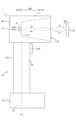
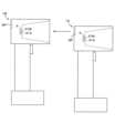
以下、本発明の実施形態に係る情報読取システムについて、バーコードやQRコード(登録商標)などのコード読取を例に説明するが、本発明は特にコード読取に限られるものではない。図1はコード読取装置の構成を模式的に示す側面図であり、図2は図1のコード読取装置が備える電気的構成の概略を示すブロック図である。ここでは、ワークWの表面Wfに付されたコードをコード読取装置1によって読み取るためにワークWの表面Wfにコード読取装置1が対向した状態において、コード読取装置1に対してワークW側を前側Sfとし、コード読取装置1に対してワークWの反対側を後ろ側Sbとする前後方向Dfsを適宜示す。Below, an information reading system according to an embodiment of the present invention will be described using code reading such as barcodes and QR codes (registered trademark), but the present invention is not particularly limited to code reading. FIG. 1 is a side view showing the configuration of a code reading device, and FIG. 2 is a block diagram showing an outline of the electrical configuration of the code reading device of FIG. 1. Here, the front-rear direction Dfs is appropriately shown, with the side of the workpiece W relative to the
図1に示すように、コード読取装置1は、ヘッド部11、グリップ部12およびグリップエンド部13を備える。グリップ部12は、ヘッド部11とグリップエンド部13との間で、前後方向Dfsに交差する軸方向Daに延設されている。換言すれば、ヘッド部11はグリップ部12の一端に対して設けられ、グリップエンド部13はグリップ部12の他端(一端の逆の端)に対して設けられる。ヘッド部11はヘッド本体111を有し、グリップ部12はグリップ本体121を有し、グリップエンド部13はグリップエンド本体131を有し、ヘッド本体111、グリップ本体121およびグリップエンド本体131は、コード読取装置1に内蔵される各部を収納するハウジング14を構成する。ユーザは。コード読取装置1のグリップ本体121を把持することで、コード読取装置1を携帯することができる。As shown in FIG. 1, the
ヘッド部11のヘッド本体111は、前側Sfに開いた開口112を有し、開口112の後ろ側Sb(換言すれば奥側)の端には配置パネル113が設けられている。コードの読み取りの際には、開口112がワークWの表面Wfに対向するとともに、配置パネル113が開口112を介してワークWの表面Wfに対向する。また、ヘッド部11は、図2に示す照明部2、撮像部3およびディスプレイSPを有する。これら照明部2、撮像部3およびディスプレイSPは、ヘッド部11に収納される。特に、照明部2の一部および撮像部3は、配置パネル113に設けられている。The
照明部2は、ワークWの表面Wfに照明光Liを照射し、撮像部3は、ワークWの表面Wfからの反射光Lrをカメラ31Aあるいは31Bにより撮像してコード画像Icを生成する。照明光Liは、照明部2から開口112を介してワークWの表面Wfに照射され、反射光Lrは、ワークWの表面Wfで照明光Liを反射することで生成され、反射光Lrは、ワークWの表面Wfから開口112を介して撮像部3のカメラ31Aあるいは31Bに入射する。The
照明部2は、拡散照明部27、直接照明部28および偏光照明部29を有する。拡散照明部27は光源Eを有し、光源Eから射出された光を拡散してからワークWの表面Wfに照射する。直接照明部28は光源281を有し、光源281から射出された光を拡散せずにワークWの表面Wfに直接照射する。偏光照明部29は光源291を有し、光源291から射出された光を偏光してからワークWの表面Wfに照射する。かかる照明部2の詳細は後述する。The
撮像部3は、2個のカメラ31A、31Bを有する。カメラ31A、31Bのそれぞれは視野を有し、対物レンズである集光レンズに視野内から入射してきた光を当該集光レンズにより個体撮像素子に集光して、視野内を撮像する。つまり、カメラ31A、31Bのそれぞれは、視野内に存在するワークWの表面Wfに対向する集光レンズによって反射光Lrを個体撮像素子に集光する。個体撮像素子は、集光レンズによって集光された反射光Lrを受光することで、コード画像Icを生成する。なお、カメラ31A、31Bそれぞれの光軸Ac(すなわち、カメラ31A、31Bそれぞれの集光レンズの光軸Ac)は、上述の前後方向Dfsに平行である。The
ディスプレイSPは、ヘッド部11のヘッド本体111の後ろ側Sbの端部に設けられており、ユーザに各種の情報を画面に表示する。The display SP is provided at the end of the rear side Sb of the
グリップ部12は、グリップ本体121の前側Sfに設けられたトリガスイッチ122を有する。ユーザは、グリップ本体121を手で握りながら、トリガスイッチ122を指で操作することができる。The
また、コード読取装置1は、当該コード読取装置1の各部を制御するコントローラ4と、当該コード読取装置1において使用されるデータや生成されたデータを記憶する記憶部5と、外部機器との通信部6とを備える。コントローラ4、記憶部5および通信部6は、ハウジング14内に収納される。コントローラ4はプロセッサ、すなわちCPU(Central Processing Unit)である。記憶部5はSSD(Solid
State Drive)等の記憶装置である。通信部6は、後述のメイン通信インターフェース831、第1通信インターフェース833、および第2通信インターフェース837を含む。 The
The
コントローラ4は、ワークWの表面Wfに照明光Liを照射する照明動作を照明部2に実行させるとともに、反射光Lrを固体撮像素子により受光してコード画像Icを生成する撮像動作を撮像部3に実行させる。さらに、コントローラ4は、撮像部3によって生成されたコード画像Icを取得して、当該コード画像Icをデコードする。こうして、照明部2による照明動作、撮像部3による撮像動作およびコントローラ4によるデコードといった一連の動作によってコード読取が実行される。例えば、コントローラ4は、ユーザによるトリガスイッチ122の操作を検知すると、コード読取を実行する。コード読取の結果、すなわちコントローラ4がコード画像Icをデコードした結果であるデコード結果Rdは、記憶部5に記憶される。The
続いては、ヘッド部11の構成、特にヘッド部11に設けられた照明部2の構成について詳述する。図3はヘッド部に設けられた拡散部材と当該拡散部材の後ろ側に設けられた照明基板とを模式的に示す正面図である。図3では、長さ方向Dlおよび幅方向Dwが示されている。ここで、長さ方向Dlおよび幅方向Dwは互いに直交するとともに、それぞれ前後方向Dfsに直交する。また、長さ方向Dlの一方側Dl1(グリップエンド部13からヘッド部11に向かう側)と、長さ方向Dlの他方側Dl2(一方側Dl1の逆側)が示され、幅方向Dwの一方側Dw1と、幅方向Dwの他方側Dw2(一方側Dw1の逆側)とが示されている。Next, the configuration of the
照明部2は、拡散部材21と、前後方向Dfsにおいて拡散部材21の後ろ側Sbに配置された照明基板25とを有する。拡散部材21は、上述のヘッド本体111の一部を構成する。なお、図3では、前後方向Dfsの前側Sfからの正面視において拡散部材21に隠れる照明基板25が破線で示されている。The
拡散部材21は、前側Sfに開いた上記の開口112を囲む壁面である開口規定部211を有する。開口規定部211は、長さ方向Dlにおいて、開口112の一方側Dl1に設けられたトップ拡散プレート212と、開口112の他方側Dl2に設けられたボトムプレート213とを有する。さらに、開口規定部211は、幅方向Dwにおいて、開口112の一方側Dl1に設けられた右拡散プレート214と、開口112の他方側Dl2に設けられた左拡散プレート215とを有する。幅方向Dwにおいてトップ拡散プレート212の両側の端部は、右拡散プレート214および左拡散プレート215に向かって他方側Dl2に屈曲する。また、長さ方向Dlにおいて、右拡散プレート214の他方側Dl2の端部は、ボトムプレート213に向かって他方側Dw2に屈曲し、左拡散プレート215の他方側Dl2の端は、ボトムプレート213に向かって一方側Dw1に屈曲する。The
トップ拡散プレート212、右拡散プレート214および左拡散プレート215は、後ろ側Sbから前側Sfへそれぞれを透過する光を拡散して、前側Sfへ射出する。具体的には、トップ拡散プレート212、右拡散プレート214および左拡散プレート215それぞれの後ろ側Sbの背面(光の入射面)にはシボ加工が施され、このシボ加工が施された背面によって光が拡散される。ただし、トップ拡散プレート212、右拡散プレート214および左拡散プレート215に光拡散機能を持たせる構成はシボ加工に限られず、例えばこれらを乳白色に加工することで光拡散機能を持たせてもよい。The
前後方向Dfsの前側Sfに向かうに連れて、カメラ31Aの集光レンズ311A(図1)の光軸Acに直交する断面における開口112の面積が広くなるように、開口112を規定する各プレート212、213、214、215は前後方向Dfsに対して傾斜するテーパー形状を有する。換言すれば、前後方向Dfs(光軸方向)の前側Sfに向かうに連れて光軸Acから離間するように各プレート212、213、214、215は前後方向Dfsに対して傾斜するテーパー形状を有する。Each of the
照明基板25は、このようにテーパー形状を有するプレート212、213、214、215より後ろ側Sbに配置される。この照明基板25は、基板251と、基板251の前側Sfの面に配列された複数の光源Eを有する。光源Eは、例えばLED(Light Emitting Diode)であり、トップ拡散プレート212、右拡散プレート214あるいは左拡散プレート215に向けて前側Sfに光を射出する。光源Eから射出されてトップ拡散プレート212、右拡散プレート214あるいは左拡散プレート215に後ろ側Sbから入射した光は、当該拡散プレート212、214あるいは215の通過に伴って拡散されて、当該拡散プレート212、214あるいは215から前側Sfに射出される。The
つまり、照明基板25の光源Eから射出された光は、拡散プレート212、214、215において拡散部材21を通過する。この際、光源Eからの光は、拡散部材21を通過するのに伴って、拡散部材21により拡散される。こうして拡散部材21で光を拡散することで生成される拡散光は、均一な面状の照明光LiとしてワークWの表面Wfに照射される。In other words, the light emitted from the light source E of the
このように、拡散部材21および照明基板25によって上述の拡散照明部27(図2)が構成されている。さらに、上述の通り、照明部2は、光源281からの光を拡散せずにワークWの表面Wfに向けて直接照射する直接照明部28と、光源291からの光を偏光して得られる光(P波あるいはS波)をワークWの表面Wfに向けて照射する偏光照明部29とを有する。図3に示すように、これら直接照明部28および偏光照明部29は、配置パネル113に配置されている。In this way, the above-mentioned diffuse illumination section 27 (Figure 2) is formed by the
したがって、コントローラ4は、拡散照明部27の光源Eを点灯させて拡散光をワークWに照射する「拡散照明」と、直接照明部28の光源281を点灯させて光源281からの光を拡散せずにワークWに照射する「直接照明」と、偏光照明部29の光源291を点灯させて偏光された光をワークWに照射する「偏光照明」とを選択的に実行することができる。Therefore, the
上述の通り、撮像部3は、2台のカメラ31A、31Bを有し、これらカメラ31A、31Bは配置パネル113に設けられている。具体的には、図3に示すように、カメラ31Aおよびカメラ31Bそれぞれの集光レンズ311A、311B(対物レンズ)が配置パネル113に嵌め込まれている。カメラ31Aは、ワークWの表面Wfからの反射光Lrを集光レンズ311Aによって固体撮像素子に集光して、当該固体撮像素子にコード画像Icを生成させる。同様に、カメラ31Bは、ワークWの表面Wfからの反射光Lrを集光レンズ311Bによって固体撮像素子に集光して、当該固体撮像素子にコード画像Icを生成させる。カメラ31Aは高分解能カメラであるのに対して、カメラ31Bは低分解能カメラであり、カメラ31Aの分解能はカメラ31Bの分解能より高い。そのため、カメラ31Aが撮像するコード画像Icの解像度は、カメラ31Bが撮像するコード画像Icの解像度よりも高い。例えば、各カメラが備えるイメージセンサの画素数が等しい場合、カメラ31Aの視野をカメラ31Bの視野よりも狭くすることで、カメラ31Aの分解能をカメラ31Bの分解能より高くすることができる。As described above, the
また、コード読取装置1に対しては、当該コード読取装置1を載置するための置台7が設けられている(図4)。図4は置台の一例を模式的に示す図である。置台7は、水平あるいは垂直な平面である設置面Fに設置された状態で使用される。置台7は、設置面Fに平行延びるベース部70を有し、ベース部70に設けられた平行な接触面701が設置面Fに接触する。また、置台7は、当該置台7に載置されるコード読取装置1のヘッド部11およびグリップエンド部13にそれぞれ対向するヘッド載置部71およびグリップエンド載置部73を有する。換言すれば、ヘッド載置部71は、ベース部70の一方の端部に設けられ、グリップエンド載置部73は、ベース部70の他方(一方の逆)の端部に設けられる。The
ヘッド載置部71は、置台7に載置されるコード読取装置1のヘッド部11に前側Sfから対向するヘッド対向面711と、ヘッド対向面711の周縁から立設された壁部712とを有する。この壁部712は、ヘッド載置部71に載置されたヘッド部11を、ヘッド対向面711に対向するように位置決めする。The
グリップエンド載置部73は、置台7に載置されるコード読取装置1のグリップエンド部13に前側Sfから対向するグリップエンド対向面731と、グリップエンド対向面731の周縁から立設された壁部732とを有する。この壁部732は、グリップエンド載置部73に載置されたグリップエンド部13をグリップエンド対向面731に対向するように位置決めする。The grip
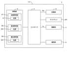
図5はコード読取装置と置台との電気的構成の第1例を示すブロック図である。図5に示すように、コード読取装置1は受電コイル18とバッテリ19を備え、置台7は送電コイル78を備える。例えば、バッテリ19はグリップエンド載置部73内に設けられ、受電コイル18はグリップエンド部13内に設けられて、図4に示すようにコード読取装置1が置台7に載置されると、送電コイル78と受電コイル18とが近接して、送電コイル78から受電コイル18に無線で電力が送られる。ただし、受電コイル18および送電コイル78を配置する位置はここの例に限られない。また、受電コイル18が受け取った電力はバッテリ19に蓄えられて、バッテリ19からコード読取装置1の各部に供給される。つまり、上述した照明部2、撮像部3、コントローラ4およびディスプレイSPなどは、バッテリ19から供給された電力によって動作する。なお、バッテリ19に代えて、SCAP(Super Capacitor)を用いても良い。Figure 5 is a block diagram showing a first example of the electrical configuration of the code reading device and the stand. As shown in Figure 5, the
また、図5に示すように、コード読取装置1および置台7で構成されるコード読取システム8は、スキャナシステム81、通信システム83および設定システム85を備えるとともに、通信システム83と通信を行う通信部87を備える。スキャナシステム81は、上述した照明部2、撮像部3、コントローラ4およびディスプレイSPを含み、コード読取装置1に設けられる。As shown in FIG. 5, the
図5の第1例では、通信システム83はコード読取装置1に設けられ、通信システム83と通信を行う通信部87は置台7に設けられる。通信システム83は、クライアントコンピュータCと通信を行うメイン通信インターフェース831を有する。メイン通信インターフェース831は、ワークWの表面Wfに付されたコードを読み取るためにユーザがコード読取装置1を使用する通常使用時において、クライアントコンピュータCと有線あるいは無線でと通信を行う。In the first example of FIG. 5, the
さらに、通信システム83は、クライアントコンピュータCと通信を行う第1通信インターフェース833を有する。第1通信インターフェース833は、クライアントコンピュータCによってコード読取装置1に設定を行う設定時においてクライアントコンピュータCと通信を行う。第1通信インターフェース833とクライアントコンピュータCとの通信は、有線および無線のいずれでも構わない。ただし、ここでは、USB(Universal Serial Bus)ケーブルを介して第1通信インターフェース833とクライアントコンピュータCとが通信を行う例について説明する。この第1通信インターフェース833は、USBメモリとしての機能を有し、当該USBメモリにRNDISドライバ834を保持する。したがって、クライアントコンピュータCと第1通信インターフェース833とが接続されると、クライアントコンピュータCは、第1通信インターフェース833のUSBメモリにアクセスして、RNDISドライバ834をダウンロードすることができる。また、クライアントコンピュータCがRNDISドライバ834を実行すると、クライアントコンピュータCと第1通信インターフェース833との間で、TCP/IPによる通信が可能となる。Furthermore, the
また、通信システム83は、第2通信インターフェース837を有する。第2通信インターフェース837は、クライアントコンピュータCとは別の外部ユニットに具備される通信部87の通信インターフェース871と通信を行うために設けられる。図5の例では、置台7に通信部87が設けられており、コード読取装置1の第2通信インターフェース837が置台7の通信部87と通信を行うことができる。第2通信インターフェース837と通信インターフェース871とは、Bluetoothによって通信を行う。ただし、第2通信インターフェース837と通信インターフェース871との通信方法は、これに限られない。The
図5の第1例では、設定システム85はコード読取装置1に設けられる。この設定システム85は、IPアドレス付与部851、名前解決部853およびウェブサーバ855を有する。IPアドレス付与部851はDHCPサーバであり、第1通信インターフェース833とクライアントコンピュータCとのTCP/IPによる通信が可能となると、クライアントコンピュータCおよびウェブサーバ855のそれぞれにプライベートIPアドレスを付与する。これによって、クライアントコンピュータCとウェブサーバ855とが接続されたプライベートネットワークを介して、クライアントコンピュータCとウェブサーバ855との間でTCP/IPによる通信が確立する。名前解決部853は、DNSサーバ(具体的には、mDNSレスポンダ)であり、IPアドレス付与部851がウェブサーバ855に付与したプライベートIPアドレスを所定のドメインに自動的に変換する。したがって、クライアントコンピュータCのウェブブラウザWBにおいてドメインを指定することで、ウェブブラウザWBからウェブサーバ855にアクセスすることができる。なお、セキュリティの観点で、プライベートネットワークおよびプライベートIPアドレスを利用することが好ましいが、パブリックネットワークおよびグローバルIPアドレスも利用することができる。In the first example of FIG. 5, the
ウェブサーバ855は設定用アプリケーション856を有する。後述するように、設定用アプリケーション856は、スキャナシステム81がコード読取を実行するためのパラメータ(撮像パラメータPaおよびデコードパラメータPb)や、メイン通信インターフェース831がクライアントコンピュータCと通信を行うための通信パラメータPcの設定を実行する。設定用アプリケーション856によって設定されたこれらのパラメータPa、Pb、Pcは記憶部5に保存される。The
特に、撮像パラメータPaおよびデコードパラメータPbはバンクB(図6)毎に保存される。図6はパラメータを記憶するバンクを模式的に示す図である。つまり、記憶部5では、複数のバンクB(N)を設定することができる(N=1、2、3、…)。このバンクB(N)は、撮像パラメータPaおよびデコードパラメータPbを保存する。換言すれば、撮像パラメータPaおよびデコードパラメータPbの少なくとも一方が異なる複数のパラメータ組み合わせをそれぞれ示す複数のバンクB(N)を記憶部5に設定することができる。そして、複数のバンクB(N)のうちの一のバンクが指定されると、コントローラ4は、当該一のバンクに保存される撮像パラメータPaおよびデコードパラメータPbを用いてコード読取を実行する。In particular, the imaging parameters Pa and the decode parameters Pb are stored for each bank B (FIG. 6). FIG. 6 is a diagram showing a schematic diagram of a bank that stores parameters. That is, a plurality of banks B(N) can be set in the memory unit 5 (N=1, 2, 3, ...). This bank B(N) stores the imaging parameters Pa and the decode parameters Pb. In other words, a plurality of banks B(N) each indicating a plurality of parameter combinations in which at least one of the imaging parameters Pa and the decode parameters Pb is different can be set in the
ここで、撮像パラメータPaは、照明部2が照明動作を実行する際の照明条件と、撮像部3が撮像動作を実行する際の撮像条件とを含む。照明条件は、拡散照明部27による拡散照明、直接照明部28による直接照明および偏光照明部29による偏光照明のうち、いずれの照明モードで照明部2に照明動作を実行させるかを示す。さらに、照明条件は、照明動作で実行される照明モードによって照射される照明光Liの明るさを示す。なお、照明光Liの明るさは、対応する光源E、281、291から射出する光の明るさを調整することで段階的に変更できる。撮像条件は、撮像部3が有するカメラ31A、31Bのうち、いずれのカメラで撮像部3に撮像動作を実行させるかを示す。さらに、撮像条件は、撮像動作で使用されるカメラの露光時間およびゲインを示す。また、デコードパラメータPbは、デコードを実行する画像処理で使用されるフィルタの係数を含む。Here, the imaging parameters Pa include the illumination conditions when the
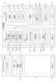
図7はパラメータの設定方法の一例を示すフローチャートである。ステップS101では、通信システム83は、第1通信インターフェース833がUSBケーブルによってクライアントコンピュータCに接続されたかを判定する。第1通信インターフェース833がクライアントコンピュータCに接続されると、RNDISドライバがインストール済みかを判定し、インストールされていない場合(ステップS101で「NO」)、第1通信インターフェース833は、USBメモリとして動作し、クライアントコンピュータCは、第1通信インターフェース833を介してRNDISドライバを取得する(ステップS102)。クライアントコンピュータCは、取得したRNDISドライバ834をインストールする(ステップS103)。RNDISドライバがインストールされている場合は、ステップS102およびS103はスキップされる(ステップS101で「YES」)。Figure 7 is a flow chart showing an example of a parameter setting method. In step S101, the
RNDISドライバ834をダウンロードしたクライアントコンピュータCにおいてRNDISドライバ834がインストールされると、クライアントコンピュータCと第1通信インターフェース833との間でTCP/IPによる通信が可能となる(ステップS104で「YES」)。こうしてTCP/IP通信が可能となると、IPアドレス付与部851は、クライアントコンピュータCおよびウェブサーバ855のそれぞれにプライベートIPアドレスを付与し(ステップS105)、名前解決部853は、所定のドメイン名とウェブサーバ855に付与されたプライベートIPアドレスとを対応付ける(ステップS106)。これによって、ユーザはウェブブラウザWBからドメインを指定することでウェブサーバ855にアクセスして、ウェブサーバ855が有する設定用アプリケーション856を操作することができる。When the
ステップS107では、設定用アプリケーション856は、ウェブブラウザWBからチューニングの実行要求を受信したかを判定する。チューニングの実行要求の受信を確認すると(ステップS107で「YES」)、設定用アプリケーション856はチューニングを実行する(図8、図9)。In step S107, the
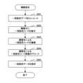
図8はチューニングの一例を示すフローチャートであり、図9はチューニングで実行される明るさ粗調整の一例を示すフローチャートである。ステップS201では、コントローラ4(チューニング部)はコードを探索する。具体的には、コントローラ4は、照明部2に照明動作を実行させつつ撮像部3に撮像動作を実行させて、コード画像Icを取得する。さらに、コントローラ4は、このコード画像Icをデコードすることでコードを探索する。このコードの探索は、その時点でコントローラ4に設定されている撮像パラメータPaおよびデコードパラメータPbを用いて実行される。すなわち、ステップS201では、その時点で設定されている撮像パラメータPaとデコードパラメータPbとを用いてコード読取が実行される。Fig. 8 is a flow chart showing an example of tuning, and Fig. 9 is a flow chart showing an example of rough brightness adjustment performed in tuning. In step S201, the controller 4 (tuning unit) searches for a code. Specifically, the
ステップS202では、コントローラ4は、照明部2が照射する照明光Liの明るさの粗調整を実行する(図9)。図9に示すように、ステップS301では、コントローラ4は、コード探索で用いた照明モードとは異なる照明モードを照明部2に設定することで、照明モードを切り換える。そして、コントローラ4は切り換えられた照明モードで読取テストを実行する(ステップS302)。この読取テストは、パラメータの調整のために実行されるコード読取であり、読取テストは、コード読取と同様に照明動作、撮像動作およびデコードを順番に実行する。In step S202, the
ステップS303では、コントローラ4は、ステップS302の読取テストに成功したかを判定する。読取テストに成功した場合(ステップS303で「YES」の場合)には、コントローラ4は、切り換え前の照明モードおよび切り換え後の照明モードのそれぞれで、照明光Liの明るさを段階的に変更しつつ、各明るさで読取テストを実行する(ステップS304)。ステップSS305では、コントローラ4は、切り換え前の照明モードと切り換え後の照明モードのうち、読取結果の優れた照明モードを決定する。例えば、照明光Liの明るさを変えながら複数回の読取テストを、各照明モードについて実行した結果、読取テストの成功回数が多い照明モードが、読取結果の優れた照明モードに決定される。続くステップS306では、コントローラ4は、読取結果の優れた照明モードについて実行された複数回の読取テストのうち成功した読取テストそれぞれでの明るさの中央値を、明るさ粗調整の結果として決定する。そして、図9の明るさ粗調整が終了する。In step S303, the
ステップS303において、ステップS302の読取テストに失敗したと判定された場合(ステップS303で「NO」の場合)には、コントローラ4は、切り換え前の照明モードで、照明光Liの明るさを段階的に変更しつつ、各明るさで読取テストを実行する(ステップS307)。続くステップS306では、コントローラ4は、切り換え前の照明モードについて実行された複数の読取テストのうち成功した読取テストそれぞれでの明るさの中央値を、明るさ粗調整の結果として決定する。そして、図9の明るさ粗調整が終了する。If it is determined in step S303 that the reading test in step S302 has failed (if "NO" in step S303), the
こうして、図9の明るさ粗調整(すなわち、図8のステップS202)では、切り換え前の照明モードおよび切り換え後の照明モードのうち、適切な一の照明モードと、当該照明モードにおける適切な明るさとが決定される。この明るさ粗調整(ステップS202)が終了すると、コントローラ4は、明るさ微調整を実行する(ステップS203)。具体的には、適切な一の照明モードで照射される照明光Liの明るさを、適切な明るさを中心とする所定範囲で変更しつつ、読取テストが実行される。例えば、同一の明るさについて複数回の読取テストが実行されて、当該明るさにおける読取テストの成功回数が求められる。こうして各明るさについて成功回数を求めたうえで、成功回数が最多となる明るさが最適な明るさとして求められる。In this way, in the rough brightness adjustment of FIG. 9 (i.e., step S202 of FIG. 8), an appropriate lighting mode and an appropriate brightness in the lighting mode are determined from the lighting modes before and after the switch. When this rough brightness adjustment (step S202) is completed, the
ステップS204では、コントローラ4は、適切な一の照明モードで照射される照明光Liの明るさを、ステップS203で求められた最適な明るさに設定しつつ、複数回の読取テストを実行する。この際、コントローラ4は、各読取テストで取得されたコード画像Icおよびデコード結果Rdを、クライアントコンピュータCに送信する(ステップS205)。具体的には、コントローラ4が取得したコード画像Icおよびデコード結果Rdは、設定用アプリケーション856によって、第1通信インターフェース833を介してクライアントコンピュータCに送信される。クライアントコンピュータCは、受信したコード画像Icおよびデコード結果RdをウェブブラウザWBに表示する。In step S204, the
ステップS206では、コントローラ4は、ステップS204の複数回の読取テストにおいて読取テストに成功した成功率が所定の閾値以上であるかを判定する。読取テストの成功率が閾値未満である場合(ステップS206で「NO」の場合)には、コントローラ4は、照明条件以外の条件、すなわち撮像パラメータPaの撮像条件あるいはデコードパラメータPbを変更して(ステップS207)、ステップS201に戻る。一方、読取テストの成功率が閾値以上である場合(ステップS206で「YES」)には、コントローラ4は、その時点で設定されている撮像パラメータPaおよびデコードパラメータPbを、チューニング結果として出力する(ステップS206)。In step S206, the
こうして、図8のチューニング(すなわち、図7のステップS108)が完了すると、設定用アプリケーション856は、コントローラ4から出力されたチューニング結果(撮像パラメータPaおよびデコードパラメータPb)を、第1通信インターフェース833を介してクライアントコンピュータCに送信するとともに(ステップS109)、チューニング結果が示す撮像パラメータPaおよびデコードパラメータPbを保持するバンクBを新たに記憶部5に設定する。Thus, when the tuning of FIG. 8 (i.e., step S108 of FIG. 7) is completed, the
続くステップS110では、設定用アプリケーション856は、メイン通信インターフェース831とクライアントコンピュータCとが通信を行うための通信パラメータPcを設定する。そして、コントローラ4は、この通信パラメータPcを記憶部5に保存するとともに(ステップS111)、クライアントコンピュータCに送信する。なお、コード読取装置1の通常使用時においては、コントローラ4により取得されたコード画像Icおよびデコード結果Rdを、メイン通信インターフェース831が当該通信パラメータPcに従ってクライアントコンピュータCに送信する。In the next step S110, the
図10はコード読取装置と置台との電気的構成の第2例を示すブロック図である。ここでは、図5の第1例との差異点を中心に説明することとし、共通点については相当符号を付して適宜説明を省略する。図10の第2例では、通信システム83がコード読取装置1ではなく、置台7に設けられ、通信部87が置台7ではなく、コード読取装置1に設けられている。また、置台7は、例えばフラッシュROM等の記憶装置である記憶部79を有し、通信パラメータPcが記憶部79に保存されている。さらに、設定システム85は、コード読取装置1ではなく、置台7に設けられている。Figure 10 is a block diagram showing a second example of the electrical configuration of the code reading device and the stand. Here, the differences from the first example in Figure 5 will be mainly explained, and the common points will be given the corresponding reference numerals and explanations will be omitted as appropriate. In the second example in Figure 10, the
かかる構成では、通常使用時においては、コード読取装置1のコントローラ4により取得されたコード画像Icおよびデコード結果Rdは、置台7のメイン通信インターフェース831を介してクライアントコンピュータCに送信される。具体的には、コントローラ4が取得したコード画像Icおよびデコード結果Rdは、コード読取装置1の通信部87に設けられた通信インターフェース871によって、置台7の通信システム83の第2通信インターフェース837に送信される。そして、メイン通信インターフェース831は、第2通信インターフェース837が受信したコード画像Icおよびデコード結果RdをクライアントコンピュータCに送信する。In this configuration, during normal use, the code image Ic and the decoded result Rd acquired by the
さらに、図7のパラメータの設定方法では、クライアントコンピュータCのウェブブラウザWBから、置台7を介して、コード読取装置1に撮像パラメータPaおよびデコードパラメータPbの設定が実行される。つまり、置台7の設定システム85に設けられたウェブサーバ855の設定用アプリケーション856は、第2通信インターフェース837および通信インターフェース871を介して、コントローラ4と通信を行う。つまり、ステップS107でチューニングの要求が確認されると、設定用アプリケーション856は、チューニングの実行指令を、第2通信インターフェース837および通信インターフェース871を介してコントローラ4に送信する。コントローラ4は、この実行指令を受信すると、チューニングを実行する(ステップS108)。また、コントローラ4はチューニングの結果として取得した撮像パラメータPaおよびデコードパラメータPbを、通信インターフェース871および第2通信インターフェース837を介して、設定システム85に出力する(ステップS207)。Furthermore, in the parameter setting method of FIG. 7, the imaging parameters Pa and the decode parameters Pb are set in the
また、メイン通信インターフェース831が置台7に設けられていることから、メイン通信インターフェース831がクライアントコンピュータCと通信を行うための通信パラメータPcは、置台7の記憶部79に保存される。つまり、ステップS110で設定された通信パラメータPcは、記憶部79に保存される(ステップS111)。コード読取装置1と置台7との間で通信をするための通信パラメータは、コード読取装置1および置台7それぞれに保存される。In addition, since the
以上のように構成されたコード読取システム8では、撮像パラメータPa、デコードパラメータPbあるいは通信パラメータPcを設定する設定用アプリケーション856とクライアントコンピュータCとにプライベートIPアドレスを付与するIPアドレス付与部851が具備されている。そして、通信システム83が第1通信インターフェース833を介してクライアントコンピュータCに接続されると(ステップS101、S104)、クライアントコンピュータCとウェブサーバ855とに対して、それぞれ同一のプライベートネットワーク上のプライベートIPアドレスがIPアドレス付与部851によって割り当てられる(ステップS105)。こうして、クライアントコンピュータCとウェブサーバ855との通信が自動的に確立される。これによって、クライアントコンピュータCのウェブブラウザWBからウェブサーバ855の設定用アプリケーション856に指令を送信して、設定用アプリケーション856に撮像パラメータPa、デコードパラメータPbあるいは通信パラメータPcを設定させることができる(ステップS108、S110)。その結果、ネットワークに関する高い技術を要さずに、コードを読み取るための設定を簡便に実行することが可能となっている。The
また、設定用アプリケーション856は、第1通信インターフェース833を介してクライアントコンピュータCに接続された状態で、第1通信インターフェース833を介してコード画像IcをウェブブラウザWBに表示させながら(ステップS205)、撮像パラメータPaあるいはデコードパラメータPBを調整するチューニングモードを有する(ステップS108、図8)。かかる構成では、ユーザは、ウェブブラウザWBに表示されたコード画像Icを確認しながら、設定のための作業をチューニングモード(ステップS108、図8)により実行することができる。The
また、設定用アプリケーション856は、第1通信インターフェース833を介してクライアントコンピュータCに接続された状態で、撮像部3に撮像させたコード画像Icのデコードをコントローラ4(制御部)に実行させ、コントローラ4によるデコード結果Rdを、第1通信インターフェース833を介してウェブブラウザWBに表示させる(ステップS205)。かかる構成では、ウェブブラウザWBへのデコード結果Rdの表示出力を、ウェブブラウザWBからの指令を通信するのと同じ第1通信インターフェース833を介して実行できるため、それぞれに対応して通信インターフェースを切り換える必要が無い。The
また、設定用アプリケーション856は、撮像パラメータPaおよびデコードパラメータPbの少なくとも一方が異なる複数のパラメータ組み合わせをそれぞれ示す複数のバンクB(N)を生成して、記憶部5に記憶する。これに対して、スキャナシステム81は、複数のバンクB(N)のうちから指定された一のバンクが示す撮像パラメータPaによって撮像部3にコード画像Icを生成させ、一のバンクが示すデコードパラメータPbによってコントローラ4にコード画像Icのデコードを実行させる。かかる構成では、ユーザは複数のバンクB(N)のうちから一のバンクを指定することで、例えばコードが付されたワークWの材質等に応じた適切な撮像パラメータPaおよびデコードパラメータPbを選択することができる。なお、ユーザによる簡易なパラメータの変更(バンク指定など)は、例えばディスプレイSPを操作することで実行できる。The
また、コード読取装置1は、スキャナシステム81と、バッテリ19と、第2通信インターフェース837とを有する携帯型のコード読取装置である。これに対して、図10の第2例では、コード読取システム8は置台7を備え、置台7は、第2通信インターフェース837を介してコード読取装置1から出力されたデコード結果Rdを含むデータを受信するとともに、バッテリ19を充電することができる。また、設定用アプリケーション856は、撮像パラメータPaおよびデコードパラメータPbをコード読取装置1に設定するとともに、コード読取装置1によるデコード結果Rdの出力に関する通信パラメータPcを置台7置台に設定する。そして、置台7は、コード読取装置1によるデコード結果Rdを、通信パラメータPcに従ってクライアントコンピュータC(外部機器)に出力する。かかる構成では、撮像パラメータPaおよびデコードパラメータPbのコード読取装置1への設定と、通信パラメータPcの置台7への設定とを簡便に実行できる。The
また、図5の第1例では、コード読取装置1は、IPアドレス付与部851により所定のドメイン名をウェブブラウザWBに割り当てられたプライベートIPアドレスに対応づけるための名前解決部853(DNSサーバ)を有する、したがって、ウェブブラウザWBからドメインが指定されることで、設定用アプリケーション856にアクセス可能となる。かかる構成では、クライアントコンピュータCとの接続の度にIPアドレスが動的に変わる場合であっても、当該IPアドレスと所定のドメインが対応付けされるため、ユーザは、IPアドレスを把握することなく、ドメインを指定するだけでウェブブラウザWBから設定用アプリケーション856にアクセスできる。In the first example of FIG. 5, the
なお、IPアドレス付与部851は、第1通信インターフェース833を介して接続されたクライアントコンピュータCに対してのみ、プライベートIPアドレスを割り当てるようにするとよい。かかる構成では、第1通信インターフェース833以外の通信インターフェース(メイン通信インターフェース831)により接続されたクライアントコンピュータCに対するIPアドレスの割り当てが禁止されるため、プライベートネットワーク上のIPアドレスの管理を簡便かつ適切に実行できる。The IP
以上に説明するように本実施形態では、コード読取システム8が本発明の「情報読取システム」の一例に相当し、撮像部3が本発明の「スキャン部」の一例に相当し、撮像パラメータPaが本発明の「スキャンパラメータ」の一例に相当し、コード画像Icが本発明の「スキャンデータ」の一例に相当し、クライアントコンピュータCが本発明の「外部コンピュータ」の一例に相当し、コントローラ4が本発明の「制御部」の一例に相当し、スキャナシステム81が本発明の「スキャナシステム」の一例に相当し、設定システム85が本発明の「設定システム」の一例に相当し、第1通信インターフェース833が本発明の「第1通信インターフェース」の一例に相当し、通信システム83が本発明の「通信システム」の一例に相当し、記憶部5あるいは記憶部79が本発明の「記憶部」の一例に相当し、ウェブサーバ855が本発明の「ウェブサーバ」の一例に相当し、IPアドレス付与部851が本発明の「IPアドレス付与部」の一例に相当し、「バッテリ19」が本発明の「蓄電部」の一例に相当する。As described above, in this embodiment, the code reading system 8 corresponds to an example of the "information reading system" of the present invention, the imaging unit 3 corresponds to an example of the "scanning unit" of the present invention, the imaging parameter Pa corresponds to an example of the "scanning parameter" of the present invention, the code image Ic corresponds to an example of the "scan data" of the present invention, the client computer C corresponds to an example of the "external computer" of the present invention, the controller 4 corresponds to an example of the "control unit" of the present invention, the scanner system 81 corresponds to an example of the "scanner system" of the present invention, the setting system 85 corresponds to an example of the "setting system" of the present invention, the first communication interface 833 corresponds to an example of the "first communication interface" of the present invention, the communication system 83 corresponds to an example of the "communication system" of the present invention, the memory unit 5 or the memory unit 79 corresponds to an example of the "memory unit" of the present invention, the web server 855 corresponds to an example of the "web server" of the present invention, the IP address assignment unit 851 corresponds to an example of the "IP address assignment unit" of the present invention, and the "battery 19" corresponds to an example of the "power storage unit" of the present invention.
なお、本発明は上記実施形態に限定されるものではなく、その趣旨を逸脱しない限りにおいて上述したものに対して種々の変更を加えることが可能である。例えば、図5の第1例と図10の第2例とは択一的に採用されるものではなく、両立が可能である。つまり、コード読取装置1および置台7のそれぞれに、通信システム83および設定システム85を設けておくことができる。この場合、コード読取装置1の第1通信インターフェース833にクライアントコンピュータCが接続された場合には、図5を用いて説明した要領で図7のパラメータ設定を行い、置台7の第1通信インターフェース833にクライアントコンピュータCが接続された場合には、図10を用いて説明した要領で図7のパラメータ設定を行えばよい。The present invention is not limited to the above embodiment, and various modifications can be made to the above without departing from the spirit of the present invention. For example, the first example in FIG. 5 and the second example in FIG. 10 are not alternatives, but can be used together. That is, the
また、メイン通信インターフェース831と、第1通信インターフェース833は、必ずしも個別に設ける必要は無く、共通の通信インターフェースとしてもよい。また、クライアントコンピュータCは、設定用PCと運用PCに分かれていても良いし、必ずしもPCではなく、PLC(Programmable Logic Controller)などの産業用機器でも良い。The
この際、例えば、クライアントコンピュータCは、その接続先がコード読取装置1であるか置台7であるかを判定する。コード読取装置1が接続先である場合には、コード読取装置1のメイン通信インターフェース831に対して通信パラメータPcを設定するように、コード読取装置1の設定用アプリケーション856に指令を出す。一方、置台7が接続先である場合には、置台7のメイン通信インターフェース831に対して通信パラメータPcを設定するように、置台7の設定用アプリケーション856に指令を出す。置台7の設定用アプリケーション856は、第2通信インターフェースを介して、設定パラメータをコード読取装置1に自動的に転送し、当該設定パラメータは、コード読取装置1の設定用アプリケーション856を介して、記憶部5に記憶される。At this time, for example, client computer C determines whether the connection destination is
ところで、上記の撮像部3は、高分解能のカメラ31Aと低分解能のカメラ31Bとを有する。そこで、図8のチューニングのステップS205においては、設定用アプリケーション856は、カメラ31Aにより取得したコード画像Icと、カメラ31Bにより取得したコード画像Icとを、第1通信インターフェース833を介してクライアントコンピュータCに送信してもよい。これによって、図11に示すように、クライアントコンピュータCは、ウェブブラウザWBに2つのコード画像Icを表示できる。図11はウェブブラウザでのコード画像の表示態様を模式的に示す図である。図11の例では、カメラ31A用の画面SR1と、カメラ31B用の画面SR2とが並んでウェブブラウザWBに設けられている。そして、カメラ31Aが取得したコード画像Icが画面SR1に表示され。カメラ31Bが取得したコード画像Icが画面SR2に表示される。The
つまり、かかる例では、撮像部3は、カメラ31B(第1カメラ)と、カメラ31Bよりも高分解能のカメラ31A(第2カメラ)とを有する。そして、設定用アプリケーション856は、カメラ31Bにより撮像されたコード画像Ic(第1コード画像)と、カメラ31Aにより撮像されたコード画像Ic(第2コード画像)とを、第1通信インターフェース833を介してウェブブラウザWBに並べて表示してこれらを対比する。かかる構成では、ユーザは、カメラ31Bによる低分解能のコード画像Icとカメラ31Aによる高分解能のコード画像Icとの対比をウェブブラウザWBによって簡便に行うことができる。That is, in this example, the
また、図7のパラメータ設定での結果を一括設定データとして圧縮することができる。図12は一括設定データの生成方法の一例を示すフローチャートである。ここの例では、コード読取装置1の記憶部5には、撮像パラメータPa、デコードパラメータPbおよび通信パラメータPcそれぞれのデフォルトを示す初期値(基準値)が保存されている。そして、ステップS401では、図7のパラメータ設定に従って設定されたパラメータ(設定パラメータ)と、初期値との差分が、設定用アプリケーション856によって算出される。具体的には、設定用アプリケーション856は、設定パラメータと初期値との排他的論理和(XOR)を算出する。さらに、設定用アプリケーション856は、ステップS401で算出された差分を例えばZIPによってデータ圧縮する(ステップS402)。そして、ステップS402でデータ圧縮された差分を、一括設定データとして記憶部5に保存する(ステップS403)。これにより、設定パラメータと基準値との間で差分の無いデータのサイズを大幅に圧縮することができる。The result of the parameter setting in FIG. 7 can be compressed as a batch setting data. FIG. 12 is a flow chart showing an example of a method for generating the batch setting data. In this example, the
かかる例では、コード読取装置1に設けられた記憶部5は、撮像パラメータPa、デコードパラメータPbおよび通信パラメータPcそれぞれのデフォルトを示す初期値(基準値)を記憶する。そして、設定用アプリケーション856は、生成した撮像パラメータPa、デコードパラメータPbおよび通信パラメータPcのうち、初期値との間で値が異なるパラメータのみを抽出して(ステップS401)、抽出されたパラメータのみを記憶部に記憶する(ステップS403)。かかる構成では、記憶部5に記憶させるデータ量を抑えることができる。特に、抽出されたパラメータをエンコードしたエンコード画像(例えばQRコード(登録商標))を生成した場合に、当該エンコード画像のサイズを小さくできるといった利点がある。In this example, the
続いては、一括設定データをエンコードしたエンコード画像の利用形態について説明する。図13は一括設定データを用いた複製設定の一例を示すフローチャートであり、図14は複製設定での動作を模式的に示す図である。この複製設定は、図14のコード読取装置1Aに設定された設定パラメータを、コード読取装置1Aと異なるコード読取装置1Bに設定するものである。Next, we will explain how to use the encoded image obtained by encoding the batch setting data. Figure 13 is a flow chart showing an example of copy setting using the batch setting data, and Figure 14 is a diagram showing the operation in copy setting. This copy setting is for setting the setting parameters set in the code reading device 1A in Figure 14 to a
ステップS501では、図12のフローチャートによって生成されて記憶部5に保存された一括設定データが、コントローラ4によってエンコードされて、エンコード画像(設定コード)が生成される。ステップS502では、複製元となるコード読取装置1Aにおいて、コントローラ4がディスプレイSPにエンコード画像を表示させる(ステップS502)。ステップS503では、複製先となるコード読取装置1Bの撮像部3が、ステップS502で表示されたエンコード画像を撮像して、当該エンコード画像のコード画像Icを取得する。ステップS504では、コード読取装置1Bにおいて、コントローラ4が当該コード画像Icのデコードを実行して、一括設定データを復元する。ステップS505では、復元された一括設定データがコード読取装置1Bの記憶部5に保存される。一括設定データは、ZIPなどによって圧縮されていても良く、その場合は、コード読取装置1Bにおいて、コントローラ4が当該圧縮されたデータを解凍した上で、一括設定データを復元し、記憶部5に保存する。In step S501, the batch setting data generated according to the flowchart of FIG. 12 and stored in the
コード読取装置1のディスプレイSPは、ヘッド部11の開口部12よりも面積が小さく構成されているため、一度に複数のエンコード画像を表示するのは困難である。したがって、一括設定データのサイズが一枚のエンコード画像に収まりきらない場合は、当該複数のエンコード画像を順次ディスプレイSPに表示させる必要がある。つまり、上記のように、一括設定データを圧縮することによって、必要なエンコード画像を減らすことができるため、コード読取装置1Bにおいて、デコードする際の負担を軽減することができる。また、コード読取装置1Aに、ディスプレイSPだけでなく、スマートフォンなどの小画面サイズの機器やPCなどの外部機器のディスプレイにエンコード画像を表示させ、コード読取装置1Bに当該エンコード画像を読み取らせて一括設定データを復元させることで、当該コード読取装置1Bの記憶部に当該一括設定データを保存させても良い。The display SP of the
かかる例では、コード読取装置1A(第1コード読取装置)で設定された撮像パラメータPa、デコードパラメータPbあるいは通信パラメータPcを、コード読取装置1B(第2コード読取装置)に簡単に反映させることができる。その結果、ネットワークに関する高い技術を要さずに、コードを読み取るための設定を簡便に実行することが可能となる。In this example, the imaging parameters Pa, the decoding parameters Pb, or the communication parameters Pc set in the code reading device 1A (first code reading device) can be easily reflected in the
本実施形態に係る情報読取システムは、ウェブ機能を用いるため、ウェブサーバと外部コンピュータとの接続管理(ネットワーク・セッション・コマンドレスポンスなど)が可能である。また、情報読取システムのチューニング中は、CPUがビジー状態となるためネットワークが切断されやすくなるが、チューニング中のデータをウェブブラウザのキャッシュや外部コンピュータのデータベース(SSDなど)に保存することが可能であるため、次回ネットワーク接続時のデータ復元が容易となる。さらに、情報読取システムは、設定用アプリケーションをZIPなどで圧縮し、ウェブブラウザからのアクセス時に解凍および展開して、ウェブブラウザに表示させることも可能であるため、情報読取システムが保持するデータサイズを小さくすることができる。The information reading system according to this embodiment uses web functions, making it possible to manage connections between a web server and an external computer (such as network session command response). In addition, while tuning the information reading system, the CPU becomes busy, making it easier for the network to be disconnected, but data during tuning can be saved in the web browser cache or in the external computer's database (such as an SSD), making it easy to restore data the next time the network is connected. Furthermore, the information reading system can compress the setting application using ZIP or the like, and decompress and expand it when accessed from the web browser to display it on the web browser, thereby reducing the size of data held by the information reading system.
この発明は、読取対象をスキャンしてスキャンデータを生成し、当該スキャンデータをデコードすることで当該読取対象に含まれる情報を読み取るための設定を行う技術全般に適用可能である。This invention can be applied to any technology that scans an object to be read, generates scan data, and decodes the scan data to set up the device to read the information contained in the object.
8…コード読取システム
3…撮像部
4…コントローラ(制御部)
81…スキャナシステム
85…設定システム
833…第1通信インターフェース
83…通信システム
5…記憶部
79…記憶部
855…ウェブサーバ
851…IPアドレス付与部
8...
81: Scanner system 85: Setting system 833: First communication interface 83: Communication system 5: Storage unit 79: Storage unit 855: Web server 851: IP address assignment unit
Claims (12)
Translated fromJapanese前記スキャナシステムに設定を行う設定システムと、
外部コンピュータと接続される第1通信インターフェースを有する通信システムと、
前記スキャン部を制御するためのスキャンパラメータ、スキャンデータに実行するデコードに関するデコードパラメータあるいはスキャンデータに実行されたデコードの結果出力に関する通信パラメータを記憶する記憶部と、
を備え、
前記設定システムは、
前記スキャンパラメータ、前記デコードパラメータあるいは前記通信パラメータを設定するための設定用アプリケーションを実行するウェブサーバと、
前記通信システムが前記第1通信インターフェースを介して前記外部コンピュータに接続されると、前記外部コンピュータと前記ウェブサーバとに対して、それぞれ同一のネットワーク上のIPアドレスを割り当てるIPアドレス付与部と、
を備え、
前記ウェブサーバは、前記IPアドレス付与部による前記IPアドレスの割り当ての後、前記第1通信インターフェースを介して前記外部コンピュータのウェブブラウザと通信可能な状態となり、
前記設定用アプリケーションは、前記ウェブブラウザから前記第1通信インターフェースを介して受信した指令に応じて前記スキャンパラメータ、前記デコードパラメータあるいは前記通信パラメータを前記記憶部に記憶する、
ことを特徴とする情報読取システム。 A scanner system including a scanning unit that scans an object to be read and generates scan data, and a control unit that executes decoding of the scan data generated by the scanning unit;
A setting system for setting the scanner system;
a communication system having a first communication interface connected to an external computer;
a storage unit that stores scan parameters for controlling the scanning unit, decode parameters related to decoding performed on the scan data, or communication parameters related to output of the result of decoding performed on the scan data;
Equipped with
The setting system includes:
a web server that executes a setting application for setting the scan parameters, the decode parameters, or the communication parameters;
an IP address assignment unit that assigns IP addresses on the same network to the external computer and the web server when the communication system is connected to the external computer via the first communication interface;
Equipped with
after the IP address assignment unit assigns the IP address, the web server is in a state capable of communicating with a web browser of the external computer via the first communication interface;
the setting application stores the scan parameters, the decode parameters, or the communication parameters in the storage unit in response to a command received from the web browser via the first communication interface;
An information reading system comprising:
請求項1に記載の情報読取システム。 the setting application has a tuning mode for adjusting the scan parameters or the decode parameters while displaying the scan data on the web browser via the first communication interface in a state where the setting application is connected to the external computer via the first communication interface.
2. An information reading system according to claim 1.
請求項1に記載の情報読取システム。 the setting application causes the control unit to decode the scan data scanned by the scanning unit while connected to the external computer via the first communication interface, and causes the control unit to display a result of the decoding by the control unit on the web browser via the first communication interface.
2. An information reading system according to claim 1.
前記設定用アプリケーションは、前記読取対象であるコードが前記第1カメラにより撮像された第1コード画像と、前記コードが前記第2カメラにより撮像された第2コード画像とを、前記第1通信インターフェースを介して前記ウェブブラウザに対比可能に表示させる、
請求項1に記載の情報読取システム。 the scanning unit includes a first camera and a second camera having at least one of a field of view, a resolution, and a focal length different from that of the first camera;
the setting application causes the web browser to comparatively display a first code image, obtained by capturing an image of the code to be read by the first camera, and a second code image, obtained by capturing an image of the code by the second camera, via the first communication interface;
2. An information reading system according to claim 1.
前記スキャナシステムは、前記バンクが示す前記スキャンパラメータによって前記スキャン部にスキャンデータを生成させ、前記バンクが示す前記デコードパラメータによって前記制御部にスキャンデータのデコードを実行させる、
請求項1に記載の情報読取システム。 The configuration application stores a bank including scan parameters and decode parameters in the storage unit;
the scanner system causes the scan unit to generate scan data according to the scan parameters indicated by the bank, and causes the control unit to decode the scan data according to the decode parameters indicated by the bank;
2. An information reading system according to claim 1.
前記第2通信インターフェースを介して、前記情報読取装置から出力されたデコードの結果を含むデータを受信するとともに、前記蓄電部を充電するための置台と、
を備え、
前記設定用アプリケーションは、前記スキャンパラメータおよび前記デコードパラメータを前記情報読取装置に設定するとともに、前記情報読取装置によるデコードの結果出力に関する通信パラメータを前記置台に設定し、
前記置台は、前記情報読取装置によるデコードの結果を、前記通信パラメータに従って外部機器に出力する、
請求項1に記載の情報読取システム。 a portable information reading device having the scanner system, a power storage unit, and a second communication interface;
a stand for receiving data including a result of decoding output from the information reading device via the second communication interface and for charging the power storage unit;
Equipped with
the setting application sets the scan parameters and the decode parameters in the information reading device, and sets communication parameters related to output of a result of decoding by the information reading device in the stand;
the stand outputs the result of the decoding by the information reading device to an external device in accordance with the communication parameters.
2. An information reading system according to claim 1.
前記ウェブブラウザは、前記ドメインの指定を受け付けて、前記名前解決部により当該ドメイン名と対応付けられた前記IPアドレスを用いて、前記設定用アプリケーションにアクセス可能となる、
請求項1に記載の情報読取システム。 the setting system further includes a name resolution unit that automatically associates a predetermined domain name with an IP address assigned to the information reading device by the IP address assignment unit,
the web browser accepts the designation of the domain, and becomes able to access the setting application by using the IP address associated with the domain name by the name resolution unit.
2. An information reading system according to claim 1.
請求項1に記載の情報読取システム。 the IP address assignment unit assigns the IP address only to an external computer connected via the first communication interface;
2. An information reading system according to claim 1.
前記設定用アプリケーションは、前記スキャンパラメータ、前記デコードパラメータおよび前記通信パラメータのうち、前記基準値との間で値が異なるパラメータのみを抽出して、抽出されたパラメータのみを前記記憶部に記憶する、
請求項1に記載の情報読取システム。 the storage unit stores reference values of the scan parameters, the decode parameters, and the communication parameters;
the setting application extracts only parameters whose values are different from the reference values from among the scan parameters, the decode parameters, and the communication parameters, and stores only the extracted parameters in the storage unit.
2. An information reading system according to claim 1.
前記情報読取システムは、前記スキャン部を収納するヘッド部と、当該ヘッド部に設けられた表示部と、を有する携帯型の情報読取装置であり、
複数の前記情報読取システムは、第1情報読取装置と、第2情報読取装置とを含み、
前記方法は、
前記第1情報読取装置の前記設定用アプリケーションにより設定された、前記スキャンパラメータ、前記デコードパラメータあるいは前記通信パラメータを、前記第1情報読取装置の制御部にエンコードさせて、設定コードを生成させる工程と、
前記第1情報読取装置の前記表示部に、生成された前記設定コードを表示させる工程と、
前記第2情報読取装置の前記スキャン部に、前記第1情報読取装置の前記表示部に表示された前記設定コードをスキャンさせて、スキャンデータを生成させる工程と、
前記第2情報読取装置の前記制御部に、前記スキャンデータのデコードを実行させる工程と、
前記第2情報読取装置の記憶部に、デコードされた前記第1情報読取装置の前記スキャンパラメータ、前記デコードパラメータあるいは前記通信パラメータを記憶させる工程と、
を備える、
ことを特徴とする情報読取システムを設定する方法。 A method for setting an information reading system using a plurality of information reading systems according to claim 1, comprising the steps of:
The information reading system is a portable information reading device having a head unit that houses the scan unit and a display unit provided on the head unit,
The plurality of information reading systems include a first information reading device and a second information reading device,
The method comprises:
a step of causing a control unit of the first information reading device to encode the scan parameter, the decode parameter, or the communication parameter set by the setting application of the first information reading device, to generate a setting code;
displaying the generated setting code on the display unit of the first information reading device;
causing the scanning unit of the second information reading device to scan the setting code displayed on the display unit of the first information reading device to generate scan data;
causing the control unit of the second information reading device to decode the scan data;
storing the decoded scan parameters, the decode parameters, or the communication parameters of the first information reading device in a storage unit of the second information reading device;
Equipped with
13. A method for setting up an information reading system, comprising:
前記記憶部は、前記スキャンパラメータ、前記デコードパラメータおよび前記通信パラメータそれぞれの基準値を記憶し、
前記ヘッド部は、前記スキャン部によるスキャンを実行するための開口部が設けられ、
前記表示部の面積は、前記開口部の面積よりも小さく、
前記設定コードを生成させる工程は、前記第1情報読取装置の前記制御部によりエンコードさせるデータとして、前記第1情報読取装置の前記設定用アプリケーションにより、前記スキャンパラメータ、前記デコードパラメータおよび前記通信パラメータのうち、前記基準値との間で値が異なるパラメータのみを抽出して差分データを取得し、当該差分データを圧縮した圧縮データを生成する工程をさらに備える
情報読取システムを設定する方法。 A method for setting up an information reading system according to claim 10, comprising the steps of:
the storage unit stores reference values of the scan parameters, the decode parameters, and the communication parameters;
the head unit is provided with an opening for performing scanning by the scanning unit,
The area of the display portion is smaller than the area of the opening portion,
The method for configuring an information reading system, wherein the step of generating the configuration code further includes a step of extracting, by the configuration application of the first information reading device, only parameters whose values differ from the reference values among the scan parameters, the decode parameters, and the communication parameters, as data to be encoded by the control unit of the first information reading device, to obtain differential data, and generating compressed data by compressing the differential data.
通信システムの第1通信インターフェースが外部コンピュータに接続された後、前記スキャン部によるスキャンを制御するためのスキャンパラメータ、スキャンデータに実行するデコードに関するデコードパラメータあるいはスキャンデータに実行されたデコードの結果出力に関する通信パラメータを設定する設定用アプリケーションを実行可能なウェブサーバと前記外部コンピュータとに対して、それぞれ同一のネットワーク上のIPアドレスをIPアドレス付与部により割り当てる工程と、
前記IPアドレス付与部による前記IPアドレスの割り当ての後、前記ウェブサーバが前記第1通信インターフェースを介して前記外部コンピュータのウェブブラウザと通信可能な状態となる工程と、
前記設定用アプリケーションが、前記ウェブブラウザから前記第1通信インターフェースを介して受信した指令に応じて前記スキャンパラメータ、前記デコードパラメータあるいは前記通信パラメータを記憶部に記憶する工程と、
を備える、
ことを特徴とするスキャナシステムの設定方法。
A method for configuring a scanner system, the method comprising: a scanner unit that scans an object to be read and generates scan data; and a control unit that decodes the scan data generated by the scanner unit; and a configuration system that performs configuration on the scanner system, the method comprising:
a step of, after a first communication interface of the communication system is connected to an external computer, allocating IP addresses on the same network to a web server capable of executing a setting application for setting scan parameters for controlling scanning by the scanning unit, decode parameters related to decoding to be performed on the scan data, or communication parameters related to output of the result of decoding performed on the scan data, and to the external computer by an IP address assignment unit;
a step of enabling the web server to communicate with a web browser of the external computer via the first communication interface after the IP address assignment unit assigns the IP address;
a step of storing the scan parameters, the decode parameters, or the communication parameters in a storage unit in response to a command received from the web browser via the first communication interface by the setting application;
Equipped with
13. A method for setting up a scanner system comprising:
Priority Applications (3)
| Application Number | Priority Date | Filing Date | Title |
|---|---|---|---|
| JP2023019190AJP2024113916A (en) | 2023-02-10 | 2023-02-10 | Information reading system, scanner system setting method, and information reading system setting method |
| US18/409,115US20240273315A1 (en) | 2023-02-10 | 2024-01-10 | Information reading system, method for setting scanner system, and method for setting information reading system |
| CN202410143755.0ACN118488145A (en) | 2023-02-10 | 2024-02-01 | Information reading system, method for setting up scanner system, and method for setting up information reading system |
Applications Claiming Priority (1)
| Application Number | Priority Date | Filing Date | Title |
|---|---|---|---|
| JP2023019190AJP2024113916A (en) | 2023-02-10 | 2023-02-10 | Information reading system, scanner system setting method, and information reading system setting method |
Publications (1)
| Publication Number | Publication Date |
|---|---|
| JP2024113916Atrue JP2024113916A (en) | 2024-08-23 |
Family
ID=92192780
Family Applications (1)
| Application Number | Title | Priority Date | Filing Date |
|---|---|---|---|
| JP2023019190APendingJP2024113916A (en) | 2023-02-10 | 2023-02-10 | Information reading system, scanner system setting method, and information reading system setting method |
Country Status (3)
| Country | Link |
|---|---|
| US (1) | US20240273315A1 (en) |
| JP (1) | JP2024113916A (en) |
| CN (1) | CN118488145A (en) |
Family Cites Families (26)
| Publication number | Priority date | Publication date | Assignee | Title |
|---|---|---|---|---|
| US7769364B2 (en)* | 2001-06-01 | 2010-08-03 | Logan James D | On demand voice mail recording system |
| US8938256B2 (en)* | 2000-08-29 | 2015-01-20 | Intel Corporation | Communication and control system using location aware devices for producing notification messages operating under rule-based control |
| US20020124111A1 (en)* | 2000-09-22 | 2002-09-05 | Narad Networks, Inc. | System and method for message transmission based on intelligent network element device identifiers |
| US7248880B2 (en)* | 2003-02-07 | 2007-07-24 | Siemens Communications, Inc. | Methods and apparatus for determining a location of a device |
| US7273179B2 (en)* | 2004-07-09 | 2007-09-25 | Datalogic Scanning, Inc. | Portable data reading device with integrated web server for configuration and data extraction |
| WO2007069209A2 (en)* | 2005-12-13 | 2007-06-21 | Visible Assets, Inc. | Dot tag protocol |
| EP2447902A4 (en)* | 2009-06-23 | 2013-04-10 | Rakuten Inc | INFORMATION PROVIDING DEVICE, CORRESPONDING METHOD, PROGRAM, AND STORAGE MEDIUM |
| KR20140018272A (en)* | 2011-03-04 | 2014-02-12 | 인터디지탈 패튼 홀딩스, 인크 | Generic packet filtering |
| US8736440B2 (en)* | 2011-06-22 | 2014-05-27 | Hana Micron America, Inc. | Early alert system and method for livestock disease detection powered by hybrid alternative energy sources |
| US11138864B2 (en)* | 2011-06-22 | 2021-10-05 | Hana Micron Inc. | Early alert system for livestock disease detection with a feedlot fence crossbar-embedded RFID antenna |
| US9094462B2 (en)* | 2011-07-13 | 2015-07-28 | Qualcomm Incorporated | Simultaneous packet data network (PDN) access |
| US9298958B1 (en)* | 2012-05-02 | 2016-03-29 | Centrak, Inc. | System and method of enhanced RTLS for improved performance in wireless networks |
| EP2713305B1 (en)* | 2012-09-27 | 2017-08-02 | Siemens Aktiengesellschaft | Method and read/write device for configuring a write/reader in an RFID assembly |
| US9857430B2 (en)* | 2012-10-15 | 2018-01-02 | Battery Technology Holdings, Llc | Tester for equipment, apparatus or component with distributed processing function |
| WO2016019456A1 (en)* | 2014-08-07 | 2016-02-11 | TrustPoint Innovation Technologies, Ltd. | Id tag authentication system and method |
| US11436544B2 (en)* | 2014-09-03 | 2022-09-06 | CloudLeaf, Inc. | System for managing an industrial workflow |
| US9826338B2 (en)* | 2014-11-18 | 2017-11-21 | Prophecy Sensorlytics Llc | IoT-enabled process control and predective maintenance using machine wearables |
| US20160245279A1 (en)* | 2015-02-23 | 2016-08-25 | Biplab Pal | Real time machine learning based predictive and preventive maintenance of vacuum pump |
| US20160245686A1 (en)* | 2015-02-23 | 2016-08-25 | Biplab Pal | Fault detection in rotor driven equipment using rotational invariant transform of sub-sampled 3-axis vibrational data |
| US20160313216A1 (en)* | 2015-04-25 | 2016-10-27 | Prophecy Sensors, Llc | Fuel gauge visualization of iot based predictive maintenance system using multi-classification based machine learning |
| US10298281B2 (en)* | 2015-05-07 | 2019-05-21 | Nxp B. V. | Establishing communication with wireless devices using orientation data |
| US10859669B2 (en)* | 2016-12-09 | 2020-12-08 | Benjamin Martinez | Hidden identification tags for objects including automobiles |
| DE102018100718A1 (en)* | 2018-01-15 | 2019-07-18 | Gcs Gmbh | Fan system, fans and procedures for operating and installing a fan |
| EP3791603A1 (en)* | 2018-05-08 | 2021-03-17 | ARRIS Enterprises LLC | Telemetry based on hfc distribution network infrastructure |
| US12424318B2 (en)* | 2018-11-28 | 2025-09-23 | Raymond Anthony Joao | Apparatus and method for providing healthcare services remotely or virtually with or using an electronic healthcare record and/or a communication network |
| WO2021091522A1 (en)* | 2019-11-04 | 2021-05-14 | Hewlett-Packard Development Company, L. P. | Anonymization protocols |
- 2023
- 2023-02-10JPJP2023019190Apatent/JP2024113916A/enactivePending
- 2024
- 2024-01-10USUS18/409,115patent/US20240273315A1/enactivePending
- 2024-02-01CNCN202410143755.0Apatent/CN118488145A/enactivePending
Also Published As
| Publication number | Publication date |
|---|---|
| US20240273315A1 (en) | 2024-08-15 |
| CN118488145A (en) | 2024-08-13 |
Similar Documents
| Publication | Publication Date | Title |
|---|---|---|
| CN107426886B (en) | Smart Lighting Device | |
| KR102472156B1 (en) | Electronic Device and the Method for Generating Depth Information thereof | |
| CN110191266B (en) | Data processing method, apparatus, electronic device, and computer-readable storage medium | |
| US10819897B2 (en) | Electronic device and method for controlling autofocus of camera | |
| CN104754134A (en) | Screen brightness adjusting method and screen brightness adjusting system | |
| AU2019406116B2 (en) | Authentication for connecting a barcode reader to a client computing device | |
| US10911687B2 (en) | Electronic device and method for controlling display of images | |
| JP2008131255A (en) | External device setting apparatus, external device setting method, and external device | |
| JP2024113916A (en) | Information reading system, scanner system setting method, and information reading system setting method | |
| KR20220028308A (en) | Application login using token transmitted from mobile device | |
| US10728418B2 (en) | Remote control system method, and program for image processing apparatus | |
| KR20190069139A (en) | Electronic device capable of increasing the task management efficiency of the digital signal processor | |
| US10324669B2 (en) | Electronic apparatus providing voice assistance based on user information | |
| KR20190104796A (en) | Method for generating plural information using camera to sense plural wave bandwidth and apparatus thereof | |
| KR102118961B1 (en) | Minimal Size Optical Fingerprint Input Apparatus for Connecting to Mobile Device | |
| JP2016039449A (en) | Device control system and device control method | |
| JP4331002B2 (en) | Mobile communication terminal | |
| US20020108047A1 (en) | Control system for image input device, especially fingerprint image input device | |
| KR100833616B1 (en) | Digital picture frame for communication network | |
| JP2021132274A (en) | Imaging device and control method thereof | |
| JP2015106884A (en) | Image processing apparatus, information processing method, and program | |
| US20210258466A1 (en) | Image capturing apparatus and its control method | |
| CN106067010A (en) | Data combination system based on distributed treatment | |
| CN115909427A (en) | Page display method, device, integrated circuit and equipment | |
| KR20040081068A (en) | Information terminal with fingerprint image acquistion device |