JP2024113247A - Power assist system and control program - Google Patents
Power assist system and control programDownload PDFInfo
- Publication number
- JP2024113247A JP2024113247AJP2023018087AJP2023018087AJP2024113247AJP 2024113247 AJP2024113247 AJP 2024113247AJP 2023018087 AJP2023018087 AJP 2023018087AJP 2023018087 AJP2023018087 AJP 2023018087AJP 2024113247 AJP2024113247 AJP 2024113247A
- Authority
- JP
- Japan
- Prior art keywords
- interference force
- disturbance
- robot
- user
- power assist
- Prior art date
- Legal status (The legal status is an assumption and is not a legal conclusion. Google has not performed a legal analysis and makes no representation as to the accuracy of the status listed.)
- Pending
Links
Images


Classifications
- B—PERFORMING OPERATIONS; TRANSPORTING
- B25—HAND TOOLS; PORTABLE POWER-DRIVEN TOOLS; MANIPULATORS
- B25J—MANIPULATORS; CHAMBERS PROVIDED WITH MANIPULATION DEVICES
- B25J9/00—Programme-controlled manipulators
- B25J9/16—Programme controls
- B25J9/1628—Programme controls characterised by the control loop
- B25J9/1633—Programme controls characterised by the control loop compliant, force, torque control, e.g. combined with position control
- B—PERFORMING OPERATIONS; TRANSPORTING
- B25—HAND TOOLS; PORTABLE POWER-DRIVEN TOOLS; MANIPULATORS
- B25J—MANIPULATORS; CHAMBERS PROVIDED WITH MANIPULATION DEVICES
- B25J13/00—Controls for manipulators
- B—PERFORMING OPERATIONS; TRANSPORTING
- B25—HAND TOOLS; PORTABLE POWER-DRIVEN TOOLS; MANIPULATORS
- B25J—MANIPULATORS; CHAMBERS PROVIDED WITH MANIPULATION DEVICES
- B25J9/00—Programme-controlled manipulators
- B25J9/0006—Exoskeletons, i.e. resembling a human figure
- B—PERFORMING OPERATIONS; TRANSPORTING
- B25—HAND TOOLS; PORTABLE POWER-DRIVEN TOOLS; MANIPULATORS
- B25J—MANIPULATORS; CHAMBERS PROVIDED WITH MANIPULATION DEVICES
- B25J9/00—Programme-controlled manipulators
- B25J9/16—Programme controls
- B25J9/1628—Programme controls characterised by the control loop
- B25J9/163—Programme controls characterised by the control loop learning, adaptive, model based, rule based expert control
Landscapes
- Engineering & Computer Science (AREA)
- Robotics (AREA)
- Mechanical Engineering (AREA)
- Manipulator (AREA)
Abstract
Description
Translated fromJapanese本発明は、パワーアシストシステム及び制御プログラムに関する。The present invention relates to a power assist system and a control program.
近年では、装着者の動作をアシストするパワーアシスト装置の開発が進められている。関連する技術は、例えば、特許文献1に開示されている。In recent years, there has been progress in the development of power assist devices that assist the wearer's movements. Related technology is disclosed, for example, in
特許文献1には、装着者の身体の軌道と目標軌道との追従誤差が小さい場合には装着者に対するアシストが小さくなり、追従誤差が大きいほど装着者に対するアシストが大きくなるANN(Assist-as-Needed)制御手法を用いたパワーアシスト装置が開示されている。
特許文献1に開示されたANN制御は、事前に指定された目標軌道に追従する制御であるため、装着者は自らの意図に沿ってロボットを自在に操ることはできない。装着者がロボットを自らの意図に沿って自在に操るためには、意図を表す装着者とロボットの間に働く干渉力の計測が必要である。しかし、センサによる干渉力の計測は装着型のパワーアシストシステムでは、力覚センサの信号を装着者自身が正確に操作できるような場合を除き一般には困難である。The ANN control disclosed in
本開示は、以上の背景に鑑みなされたものであり、力覚センサでの計測が難しいロボットを装着したユーザから当該ロボットに付与される干渉力を精度良く推定することにより、ユーザの意図に沿ったパワーアシストを行うことが可能なパワーアシストシステム及び制御プログラムを提供することを目的とする。The present disclosure has been made in consideration of the above background, and aims to provide a power assist system and control program that can perform power assist in line with the user's intentions by accurately estimating the interference force applied to a robot by a user wearing the robot, which is difficult to measure with a force sensor.
本開示にかかるパワーアシストシステムは、ユーザに装着され、前記ユーザの動作をアシストする駆動源を有する、ロボットと、前記ユーザから前記ロボットに付与された干渉力を推定する干渉力推定部と、所定の動特性を持つ仮想物体における、前記干渉力推定部によって推定された前記干渉力に対する目標速度を生成する、アドミッタンスモデルと、前記ロボットの速度が前記目標速度に追従するような制御トルクで前記駆動源を駆動させる制御部と、を備えた、パワーアシストシステムであって、前記干渉力推定部は、前記ロボットの運動量に基づいて外乱を検出する外乱オブザーバと、リザバー層の重み付けを確率的に割り振りながら前記外乱に応じた前記干渉力についての学習が行われたESN学習モデルを用いて、前記外乱オブザーバによって検出された前記外乱に応じた前記干渉力を推定する推定部と、を有する。このパワーアシストシステムは、ロボットを装着したユーザから当該ロボットに付与される干渉力を精度良く推定することにより、高精度なアドミッタンス制御を実現することができるため、ユーザの意図に沿ったパワーアシストを行うことができる。The power assist system according to the present disclosure is a power assist system including a robot that is worn by a user and has a driving source that assists the user's actions, an interference force estimation unit that estimates an interference force applied to the robot by the user, an admittance model that generates a target speed for the interference force estimated by the interference force estimation unit in a virtual object having a predetermined dynamic characteristic, and a control unit that drives the driving source with a control torque such that the speed of the robot follows the target speed, and the interference force estimation unit includes a disturbance observer that detects a disturbance based on the momentum of the robot, and an estimation unit that estimates the interference force corresponding to the disturbance detected by the disturbance observer using an ESN learning model in which learning about the interference force corresponding to the disturbance is performed while stochastically allocating weighting of a reservoir layer. This power assist system can realize highly accurate admittance control by accurately estimating the interference force applied to the robot by the user wearing the robot, and can perform power assist according to the user's intention.
本開示にかかる制御プログラムは、ユーザに装着され、前記ユーザの動作をアシストする駆動源を有する、ロボット、を備えたパワーアシストシステムによるアシスト処理をコンピュータに実行させる制御プログラムであって、前記ユーザから前記ロボットに付与された干渉力を推定する処理と、所定の動特性を持つ仮想物体における前記干渉力に対する目標速度を生成する処理と、前記ロボットの速度が前記目標速度に追従するような制御トルクで前記駆動源を駆動させる処理と、をコンピュータに実行させ、前記干渉力を推定する処理では、外乱オブザーバによって、前記ロボットの運動量に基づいて外乱を検出する処理と、リザバー層の重み付けを確率的に割り振りながら前記外乱に応じた前記干渉力についての学習が行われたESN学習モデルを用いて、前記外乱オブザーバによって検出された前記外乱に応じた前記干渉力を推定する処理と、をコンピュータに実行させる。この制御プログラムは、ロボットを装着したユーザから当該ロボットに付与される干渉力を精度良く推定することにより、高精度なアドミッタンス制御を実現することができるため、ユーザの意図に沿ったパワーアシストを行うことができる。The control program according to the present disclosure is a control program that causes a computer to execute an assist process using a power assist system that includes a robot that is worn by a user and has a drive source that assists the user's actions, and causes the computer to execute the following processes: estimating an interference force applied to the robot by the user; generating a target speed for the interference force in a virtual object having a predetermined dynamic characteristic; and driving the drive source with a control torque such that the speed of the robot follows the target speed. In the process of estimating the interference force, the computer executes the following processes: detecting a disturbance based on the momentum of the robot using a disturbance observer; and estimating the interference force corresponding to the disturbance detected by the disturbance observer using an ESN learning model that has learned about the interference force corresponding to the disturbance while stochastically allocating a weighting of a reservoir layer. This control program can realize highly accurate admittance control by accurately estimating the interference force applied to the robot by the user wearing the robot, and can perform power assist according to the user's intention.
本開示により、力覚センサでの計測が難しいロボットを装着したユーザから当該ロボットに付与される干渉力を精度良く推定することにより、ユーザの意図に沿ったパワーアシストを行うことが可能なパワーアシストシステム及び制御プログラムを提供することができる。This disclosure makes it possible to provide a power assist system and control program that can perform power assist in line with the user's intentions by accurately estimating the interference force exerted on a robot by a user wearing the robot, which is difficult to measure with a force sensor.
以下、発明の実施形態を通じて本発明を説明するが、特許請求の範囲に係る発明を以下の実施形態に限定するものではない。また、実施形態で説明する構成の全てが課題を解決するための手段として必須であるとは限らない。説明の明確化のため、以下の記載及び図面は、適宜、省略、及び簡略化がなされている。各図面において、同一の要素には同一の符号が付されており、必要に応じて重複説明は省略されている。The present invention will be described below through embodiments of the invention, but the invention according to the claims is not limited to the following embodiments. Furthermore, not all of the configurations described in the embodiments are necessarily essential as means for solving the problems. For clarity of explanation, the following description and drawings have been omitted and simplified as appropriate. In each drawing, the same elements are given the same reference numerals, and duplicate explanations have been omitted as necessary.
<実施の形態1>
図1は、実施の形態1にかかるパワーアシストシステム1の構成を示すブロック図である。本実施の形態にかかるパワーアシストシステム1は、ロボットを装着したユーザから当該ロボットに付与される干渉力を精度良く推定することにより、高精度なアドミッタンス制御を実現することができるため、ユーザの意図に沿ったパワーアシストを行うことができる。以下、具体的に説明する。<First embodiment>
Fig. 1 is a block diagram showing the configuration of a
図1に示すように、パワーアシストシステム1は、ロボット11と、干渉力推定部12と、アドミッタンスモデル13と、演算器14と、減算器15と、NNベース適応制御部16と、を備える。As shown in FIG. 1, the
ロボット11は、動作支援の必要なユーザU1に装着され、ユーザU1の動きをアシストする。例えば、ロボット11は、ユーザU1の下肢の各部位を支持する支持部材と、ユーザU1の下肢の各関節に対応して設けられた回転部材と、を備える。各回転部材は、複数の支持部材のうち2つの支持部材を回転自在に接続し、且つ、当該2つの支持部材を回転駆動させるサーボモータ等のアクチュエータ(駆動源)と、ロータリエンコーダ等の角度センサと、を有する。なお、ロボット11は、ユーザU1の下肢に取り付けられる場合に限られず、ユーザU1の上肢、又は、ユーザU1の上肢及び下肢、に取り付けられてもよい。The
干渉力推定部12は、ロボット11を装着したユーザU1から当該ロボット11に直接的に付与される力である干渉力を推定する。したがって、干渉力は、ユーザU1の動作の意図を表しているとも言える。具体的には、干渉力推定部12は、MBO121と、ESN122と、推定部123と、を備える。The interference

本実施の形態では、外乱オブザーバの一種であるMBOが用いられた場合を例に説明しているが、それには限定されず、MBO以外の種類の外乱オブザーバが用いられてもよい。また、本実施の形態では、リザバーコンピューティング手法の一種であるESNが用いられた場合を例に説明しているが、それには限定されず、ESN以外の種類のリザバーコンピューティング手法が用いられてもよい。In this embodiment, an example is described in which an MBO, which is a type of disturbance observer, is used, but this is not limited to this, and a type of disturbance observer other than an MBO may be used. Also, in this embodiment, an example is described in which an ESN, which is a type of reservoir computing method, is used, but this is not limited to this, and a type of reservoir computing method other than an ESN may be used.

NNベース適応制御部16は、ニューラルネットワークを用いて構成された適応制御系である。具体的には、NNベース適応制御部16は、ニューラルネットワークにおける適応則(適応項)により、ユーザU1とロボット11の間のダイナミクスの物理パラメータが未知な場合でも速度誤差
ここで、


なお、オブザーバゲインは正定行列であるものとする。
It is assumed that the observer gain is a positive definite matrix.
それにより、以下の式(5)が成り立つ。

続いて、推定部123におけるESNと呼ばれる学習モデルを説明する。Next, we will explain the learning model called ESN in the


また、

なお、漏れ率αが大きいほど、新たな入力情報の寄与率が小さくなり、漏れ率αが小さいほど、新たな入力情報の寄与率が大きくなる。Note that the larger the leak rate α, the smaller the contribution rate of new input information, and the smaller the leak rate α, the greater the contribution rate of new input information.


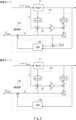
なお、本実施の形態の図3の例では、干渉力推定部12において、MBO121の出力がESN122に入力される直列推定方法が採用されている。以下、図3を用いて簡単に説明する。In the example of this embodiment shown in FIG. 3, the interference


それに対し、図5に示すように、MBOのみによる干渉力推定では、干渉トルクの検証データ(点線)と、推定結果である推定干渉トルクと、の誤差が大きい。したがって、MBOのみによる干渉力推定では、干渉トルクの推定精度は低い。In contrast, as shown in Figure 5, when estimating the interference force using only the MBO, there is a large error between the verification data for the interference torque (dotted line) and the estimated interference torque, which is the estimation result. Therefore, when estimating the interference force using only the MBO, the estimation accuracy of the interference torque is low.
このように、本実施の形態にかかるパワーアシストシステム1は、力覚センサを用いる代わりに、MBO121とESN122とを組み合わせて用いることにより、ロボットを装着したユーザユーザから当該ロボットに付与される干渉力を精度良く推定することができる。それにより、本実施の形態にかかるパワーアシストシステム1は、高精度なアドミッタンス制御を実現することができるため、ユーザの意図に沿ったパワーアシストを行うことができる。In this way, the
なお、本発明は上記実施の形態に限られたものではなく、趣旨を逸脱しない範囲で適宜変更することが可能である。The present invention is not limited to the above embodiment, and can be modified as appropriate without departing from the spirit and scope of the invention.
本実施の形態では、干渉力推定部12において、MBO121の出力がESN122に入力される直列推定方法が採用されている場合を例に説明したが、それには限定されない。干渉力推定部12は、MBO121とESN122とが並列に用いられる並列推定方法が採用されてもよい。以下、図6を用いて簡単に説明する。In this embodiment, the case where the interference

図6に示すような並列推定方法が採用されたパワーアシストシステム1でも、直列推定方法が採用されたパワーアシストシステム1と同等の効果を奏することができる。A
さらに、本開示は、パワーアシストシステム1によるアシスト処理の一部又は全部を、CPU(Central Processing Unit)にコンピュータプログラムを実行させることにより実現することが可能である。Furthermore, this disclosure can realize part or all of the assist processing by the
上述したプログラムは、コンピュータに読み込まれた場合に、実施形態で説明された1又はそれ以上の機能をコンピュータに行わせるための命令群(又はソフトウェアコード)を含む。プログラムは、非一時的なコンピュータ可読媒体又は実体のある記憶媒体に格納されてもよい。限定ではなく例として、コンピュータ可読媒体又は実体のある記憶媒体は、RAM(Random-Access Memory)、ROM(Read-Only Memory)、フラッシュメモリ、SSD(Solid-State Drive)又はその他のメモリ技術、CD-ROM、DVD(Digital Versatile Disc)、Blu-ray(登録商標)ディスク又はその他の光ディスクストレージ、磁気カセット、磁気テープ、磁気ディスクストレージ又はその他の磁気ストレージデバイスを含む。プログラムは、一時的なコンピュータ可読媒体又は通信媒体上で送信されてもよい。限定ではなく例として、一時的なコンピュータ可読媒体又は通信媒体は、電気的、光学的、音響的、またはその他の形式の伝搬信号を含む。The above-mentioned program includes a set of instructions (or software code) that, when loaded into a computer, causes the computer to perform one or more functions described in the embodiments. The program may be stored on a non-transitory computer-readable medium or a tangible storage medium. By way of example and not limitation, computer-readable media or tangible storage media include RAM (Random-Access Memory), ROM (Read-Only Memory), flash memory, SSD (Solid-State Drive) or other memory technology, CD-ROM, DVD (Digital Versatile Disc), Blu-ray (registered trademark) disk or other optical disk storage, magnetic cassette, magnetic tape, magnetic disk storage or other magnetic storage device. The program may be transmitted on a temporary computer-readable medium or a communication medium. By way of example and not limitation, transitory computer-readable media or communication media include electrical, optical, acoustic, or other forms of propagated signals.
上記の実施の形態の一部又は全部は、以下の付記のようにも記載されうるが、以下には限られない。A part or all of the above embodiments may be described as follows, but is not limited to the following:
1 パワーアシストシステム
11 ロボット
12 干渉力推定部
13 アドミッタンスモデル
14 演算器
15 減算器
16 NNベース適応制御部
121 MBO
122 ESN
123 推定部 REFERENCE SIGNS
122 ESN
123 Estimation Department
Claims (5)
Translated fromJapanese前記ユーザから前記ロボットに付与された干渉力を推定する干渉力推定部と、
所定の動特性を持つ仮想物体における、前記干渉力推定部によって推定された前記干渉力に対する目標速度を生成する、アドミッタンスモデルと、
前記ロボットの速度が前記目標速度に追従するような制御トルクで前記駆動源を駆動させる制御部と、
を備えた、パワーアシストシステムであって、
前記干渉力推定部は、
前記ロボットの運動量に基づいて外乱を検出する外乱オブザーバと、
リザバー層の重み付けを確率的に割り振りながら前記外乱に応じた前記干渉力についての学習が行われたESN学習モデルを用いて、前記外乱オブザーバによって検出された前記外乱に応じた前記干渉力を推定する推定部と、
を有する、パワーアシストシステム。 A robot that is worn by a user and has a drive source that assists the user's movements;
an interference force estimation unit that estimates an interference force applied to the robot by the user;
an admittance model that generates a target velocity for the interference force estimated by the interference force estimation unit for a virtual object having a predetermined dynamic characteristic;
a control unit that drives the driving source with a control torque such that the velocity of the robot follows the target velocity;
A power assist system comprising:
The interference force estimation unit is
a disturbance observer that detects a disturbance based on a momentum of the robot;
an estimation unit that estimates the interference force corresponding to the disturbance detected by the disturbance observer using an ESN learning model that has been learned about the interference force corresponding to the disturbance while stochastically allocating a weighting of a reservoir layer;
A power assist system having:
前記推定部は、動作モードが推定モードの場合に、前記ESN学習モデルを用いて、前記外乱オブザーバによって検出された前記外乱に応じた前記干渉力を推定する、
請求項1に記載のパワーアシストシステム。 the ESN learning model is configured to perform learning regarding the interference force corresponding to the disturbance based on teacher data of the interference force when the operation mode is a learning mode,
The estimation unit estimates the interference force corresponding to the disturbance detected by the disturbance observer by using the ESN learning model when the operation mode is an estimation mode.
The power assist system according to claim 1 .
前記推定部は、動作モードが推定モードの場合に、前記ESN学習モデルを用いて推定された前記干渉力と、前記外乱オブザーバによって検出された前記外乱と、を加算した値を、前記干渉力として推定する、
請求項1に記載のパワーアシストシステム。 the ESN learning model is configured to perform learning using a difference between the interference force and the disturbance as training data when the operation mode is a learning mode,
When the operation mode is an estimation mode, the estimation unit estimates, as the interference force, a value obtained by adding the interference force estimated using the ESN learning model and the disturbance detected by the disturbance observer.
The power assist system according to claim 1 .
前記ESN学習モデルは、ESN(Echo State Network)である、
請求項1に記載のパワーアシストシステム。 The disturbance observer is a Momentum Based Observer,
The ESN learning model is ESN (Echo State Network),
The power assist system according to claim 1 .
前記ユーザから前記ロボットに付与された干渉力を推定する処理と、
所定の動特性を持つ仮想物体における前記干渉力に対する目標速度を生成する処理と、
前記ロボットの速度が前記目標速度に追従するような制御トルクで前記駆動源を駆動させる処理と、
をコンピュータに実行させ、
前記干渉力を推定する処理では、
外乱オブザーバによって、前記ロボットの運動量に基づいて外乱を検出する処理と、
リザバー層の重み付けを確率的に割り振りながら前記外乱に応じた前記干渉力についての学習が行われたESN学習モデルを用いて、前記外乱オブザーバによって検出された前記外乱に応じた前記干渉力を推定する処理と、
をコンピュータに実行させる制御プログラム。 A control program for causing a computer to execute an assist process by a power assist system including a robot that is worn by a user and has a drive source for assisting a movement of the user, the control program comprising:
A process of estimating an interference force applied to the robot by the user;
generating a target velocity for said interference force for a virtual object having a predetermined dynamic characteristic;
a process of driving the driving source with a control torque such that the velocity of the robot follows the target velocity;
Run the following on your computer:
In the process of estimating the interference force,
detecting a disturbance based on a motion amount of the robot by a disturbance observer;
A process of estimating the interference force corresponding to the disturbance detected by the disturbance observer using an ESN learning model in which learning about the interference force corresponding to the disturbance is performed while stochastically allocating a weighting of a reservoir layer;
A control program that causes a computer to execute the above.
Priority Applications (2)
| Application Number | Priority Date | Filing Date | Title |
|---|---|---|---|
| JP2023018087AJP2024113247A (en) | 2023-02-09 | 2023-02-09 | Power assist system and control program |
| US18/544,759US20240269839A1 (en) | 2023-02-09 | 2023-12-19 | Power assist system and storage medium |
Applications Claiming Priority (1)
| Application Number | Priority Date | Filing Date | Title |
|---|---|---|---|
| JP2023018087AJP2024113247A (en) | 2023-02-09 | 2023-02-09 | Power assist system and control program |
Publications (1)
| Publication Number | Publication Date |
|---|---|
| JP2024113247Atrue JP2024113247A (en) | 2024-08-22 |
Family
ID=92216872
Family Applications (1)
| Application Number | Title | Priority Date | Filing Date |
|---|---|---|---|
| JP2023018087APendingJP2024113247A (en) | 2023-02-09 | 2023-02-09 | Power assist system and control program |
Country Status (2)
| Country | Link |
|---|---|
| US (1) | US20240269839A1 (en) |
| JP (1) | JP2024113247A (en) |
Families Citing this family (1)
| Publication number | Priority date | Publication date | Assignee | Title |
|---|---|---|---|---|
| CN120010260B (en)* | 2025-02-12 | 2025-09-05 | 中国科学院空间应用工程与技术中心 | Dynamic control method, system, device and medium for floating-based space robot |
- 2023
- 2023-02-09JPJP2023018087Apatent/JP2024113247A/enactivePending
- 2023-12-19USUS18/544,759patent/US20240269839A1/enactivePending
Also Published As
| Publication number | Publication date |
|---|---|
| US20240269839A1 (en) | 2024-08-15 |
Similar Documents
| Publication | Publication Date | Title |
|---|---|---|
| JP6746292B2 (en) | Language model learning method and device, language recognition method and device | |
| CN111281743A (en) | An adaptive compliance control method for an upper limb rehabilitation exoskeleton robot | |
| JP2020009444A (en) | Method and apparatus for processing parameters in a neural network | |
| WO2019197613A1 (en) | Graph neural networks representing physical systems | |
| CN112218744A (en) | System and method for learning agile movement of multi-legged robot | |
| CN112596534A (en) | Gait training method and device for quadruped robot based on deep reinforcement learning, electronic equipment and medium | |
| JP7398373B2 (en) | Control device, system, control method, and program | |
| Lou et al. | Deep learning method for 3-DOF motion prediction of unmanned surface vehicles based on real sea maneuverability test | |
| US11631028B2 (en) | Method of updating policy for controlling action of robot and electronic device performing the method | |
| CN114529010B (en) | A robot autonomous learning method, device, equipment and storage medium | |
| JP2024113247A (en) | Power assist system and control program | |
| CN112631128A (en) | Robot assembly skill learning method and system based on multi-mode heterogeneous information fusion | |
| WO2021060104A1 (en) | Information processing device, information processing system, and information processing method | |
| CN110705105B (en) | A modeling method and system for robot inverse dynamics model | |
| CN107590340A (en) | A kind of mechanical arm external force method of estimation and device | |
| CN112932897B (en) | Method and device for rehabilitation robot to move and rehabilitation robot | |
| JP2021508886A (en) | How to predict the movement of an object, how to adjust a motion model, how to derive a given quantity, and how to generate a virtual reality view | |
| CN111563602A (en) | learning systems and methods | |
| CN113070878A (en) | Robot control method based on impulse neural network, robot and storage medium | |
| JP2019175275A (en) | Control system, controller, control program, learning data creation method, and learning method | |
| JPWO2022034679A5 (en) | Behavior learning device, behavior learning method, behavior estimation device, behavior estimation method, and program | |
| CN113610218B (en) | Load identification method, system, device and storage medium based on extreme learning machine | |
| Lowrey et al. | Real-time state estimation with whole-body multi-contact dynamics: A modified UKF approach | |
| CN110147891B (en) | Method and device applied to reinforcement learning training process and electronic equipment | |
| CN116476067B (en) | Robot motion control method, device and medium |
Legal Events
| Date | Code | Title | Description |
|---|---|---|---|
| A621 | Written request for application examination | Free format text:JAPANESE INTERMEDIATE CODE: A621 Effective date:20250917 |