JP2024110966A - Systems and methods for providing a tibial baseplate - Patents.com - Google Patents
Systems and methods for providing a tibial baseplate - Patents.comDownload PDFInfo
- Publication number
- JP2024110966A JP2024110966AJP2024080096AJP2024080096AJP2024110966AJP 2024110966 AJP2024110966 AJP 2024110966AJP 2024080096 AJP2024080096 AJP 2024080096AJP 2024080096 AJP2024080096 AJP 2024080096AJP 2024110966 AJP2024110966 AJP 2024110966A
- Authority
- JP
- Japan
- Prior art keywords
- spacer
- tibial
- tibia
- base plate
- knee
- Prior art date
- Legal status (The legal status is an assumption and is not a legal conclusion. Google has not performed a legal analysis and makes no representation as to the accuracy of the status listed.)
- Pending
Links
Images


Classifications
- A—HUMAN NECESSITIES
- A61—MEDICAL OR VETERINARY SCIENCE; HYGIENE
- A61B—DIAGNOSIS; SURGERY; IDENTIFICATION
- A61B17/00—Surgical instruments, devices or methods
- A61B17/16—Instruments for performing osteoclasis; Drills or chisels for bones; Trepans
- A61B17/17—Guides or aligning means for drills, mills, pins or wires
- A61B17/1739—Guides or aligning means for drills, mills, pins or wires specially adapted for particular parts of the body
- A61B17/1764—Guides or aligning means for drills, mills, pins or wires specially adapted for particular parts of the body for the knee
- A—HUMAN NECESSITIES
- A61—MEDICAL OR VETERINARY SCIENCE; HYGIENE
- A61B—DIAGNOSIS; SURGERY; IDENTIFICATION
- A61B17/00—Surgical instruments, devices or methods
- A61B17/02—Surgical instruments, devices or methods for holding wounds open, e.g. retractors; Tractors
- A61B17/025—Joint distractors
- A—HUMAN NECESSITIES
- A61—MEDICAL OR VETERINARY SCIENCE; HYGIENE
- A61B—DIAGNOSIS; SURGERY; IDENTIFICATION
- A61B17/00—Surgical instruments, devices or methods
- A61B17/14—Surgical saws
- A61B17/15—Guides therefor
- A61B17/154—Guides therefor for preparing bone for knee prosthesis
- A61B17/155—Cutting femur
- A—HUMAN NECESSITIES
- A61—MEDICAL OR VETERINARY SCIENCE; HYGIENE
- A61B—DIAGNOSIS; SURGERY; IDENTIFICATION
- A61B17/00—Surgical instruments, devices or methods
- A61B17/14—Surgical saws
- A61B17/15—Guides therefor
- A61B17/154—Guides therefor for preparing bone for knee prosthesis
- A61B17/157—Cutting tibia
- A—HUMAN NECESSITIES
- A61—MEDICAL OR VETERINARY SCIENCE; HYGIENE
- A61B—DIAGNOSIS; SURGERY; IDENTIFICATION
- A61B17/00—Surgical instruments, devices or methods
- A61B17/16—Instruments for performing osteoclasis; Drills or chisels for bones; Trepans
- A61B17/1662—Instruments for performing osteoclasis; Drills or chisels for bones; Trepans for particular parts of the body
- A61B17/1675—Instruments for performing osteoclasis; Drills or chisels for bones; Trepans for particular parts of the body for the knee
- A—HUMAN NECESSITIES
- A61—MEDICAL OR VETERINARY SCIENCE; HYGIENE
- A61B—DIAGNOSIS; SURGERY; IDENTIFICATION
- A61B17/00—Surgical instruments, devices or methods
- A61B17/16—Instruments for performing osteoclasis; Drills or chisels for bones; Trepans
- A61B17/17—Guides or aligning means for drills, mills, pins or wires
- A61B17/1717—Guides or aligning means for drills, mills, pins or wires for applying intramedullary nails or pins
- A—HUMAN NECESSITIES
- A61—MEDICAL OR VETERINARY SCIENCE; HYGIENE
- A61B—DIAGNOSIS; SURGERY; IDENTIFICATION
- A61B17/00—Surgical instruments, devices or methods
- A61B17/16—Instruments for performing osteoclasis; Drills or chisels for bones; Trepans
- A61B17/1604—Chisels; Rongeurs; Punches; Stamps
- A—HUMAN NECESSITIES
- A61—MEDICAL OR VETERINARY SCIENCE; HYGIENE
- A61B—DIAGNOSIS; SURGERY; IDENTIFICATION
- A61B17/00—Surgical instruments, devices or methods
- A61B17/56—Surgical instruments or methods for treatment of bones or joints; Devices specially adapted therefor
- A61B17/58—Surgical instruments or methods for treatment of bones or joints; Devices specially adapted therefor for osteosynthesis, e.g. bone plates, screws or setting implements
- A61B17/68—Internal fixation devices, including fasteners and spinal fixators, even if a part thereof projects from the skin
- A61B17/72—Intramedullary devices, e.g. pins or nails
- A—HUMAN NECESSITIES
- A61—MEDICAL OR VETERINARY SCIENCE; HYGIENE
- A61B—DIAGNOSIS; SURGERY; IDENTIFICATION
- A61B17/00—Surgical instruments, devices or methods
- A61B17/02—Surgical instruments, devices or methods for holding wounds open, e.g. retractors; Tractors
- A61B17/025—Joint distractors
- A61B2017/0268—Joint distractors for the knee
Landscapes
- Health & Medical Sciences (AREA)
- Surgery (AREA)
- Life Sciences & Earth Sciences (AREA)
- Medical Informatics (AREA)
- Animal Behavior & Ethology (AREA)
- Veterinary Medicine (AREA)
- Public Health (AREA)
- Engineering & Computer Science (AREA)
- Biomedical Technology (AREA)
- Heart & Thoracic Surgery (AREA)
- General Health & Medical Sciences (AREA)
- Molecular Biology (AREA)
- Nuclear Medicine, Radiotherapy & Molecular Imaging (AREA)
- Dentistry (AREA)
- Oral & Maxillofacial Surgery (AREA)
- Orthopedic Medicine & Surgery (AREA)
- Physical Education & Sports Medicine (AREA)
- Transplantation (AREA)
- Prostheses (AREA)
- Surgical Instruments (AREA)
- Vehicle Step Arrangements And Article Storage (AREA)
Abstract
Description
Translated fromJapanese1.関連出願の相互参照
本出願は、2017年10月13日に出願され、「KNEE ARTHROPLASTY SYSTEMS AND METHODS」と題する米国仮特許仮出願第62/572,245号(代理人整理番号第7782.58号)、2017年6月12日に出願され、「KNEE ARTHROPLASTY SYSTEMS AND METHODS」と題する米国仮特許出願第62/518,479号(代理人整理番号第7782.57号)、および2016年11月30日に出願され、「KNEE ARTHROPLASTY SYSTEMS AND METHODS」と題する米国仮特許出願第62/428,480号(代理人整理番号第7782.55号)に対する優先権を主張し、そのすべての開示内容が参照により本明細書に組み込まれる。1. CROSS-REFERENCE TO RELATED APPLICATIONS This application is related to U.S. Provisional Patent Application No. 62/572,245 (Attorney Docket No. 7782.58), filed on October 13, 2017, entitled "KNEE ARTHROPLASTY SYSTEMS AND METHODS," U.S. Provisional Patent Application No. 62/518,479 (Attorney Docket No. 7782.57), filed on June 12, 2017, entitled "KNEE ARTHROPLASTY SYSTEMS AND METHODS," and U.S. Provisional Patent Application No. 62/518,479 (Attorney Docket No. 7782.57), filed on November 30, 2016, entitled "KNEE ARTHROPLASTY SYSTEMS AND METHODS." This application claims priority to U.S. Provisional Patent Application No. 62/428,480 (Attorney Docket No. 7782.55), entitled "METHODS," the entire disclosure of which is incorporated herein by reference.
2.技術分野
本発明は、靭帯の引張、靭帯の平衡、骨の切断を提供するように、および/または別様に関節を準備して、関節の関節形成術中にプロテーゼインプラントを受容するように構成されているシステムおよび方法に関する。特に、記載されたシステムおよび方法のいくつかの実装形態は、膝関節における1つ以上の大腿骨および/または脛骨プロテーゼの移植のための準備において、膝関節における靭帯の引張、靭帯の平衡、および/または骨の切断を提供する。2. Technical Field The present invention relates to systems and methods configured to provide ligament tensioning, ligament balancing, bone cutting, and/or otherwise prepare a joint to receive a prosthetic implant during arthroplasty of the joint. In particular, some implementations of the described systems and methods provide ligament tensioning, ligament balancing, and/or bone cutting in a knee joint in preparation for implantation of one or more femoral and/or tibial prostheses in the knee joint.
3.背景技術
膝関節形成術中に、外科医は、典型的には、既存の骨および軟骨の切除を行い、脛骨および大腿骨を成形し、インプラントの接合面に適合させるために、膝関節に接近しなければならない。いくつかの関節形成術処置では、膝および膝蓋骨の周囲軟組織構造における切開部のサイズを最小化することによって、膝関節へのアプローチの侵襲性を最小化する努力をしている。軟組織構造を保存することによっても、これらの組織によって提供される支持のいくつかが保存される。しかしながら、膝を囲む軟組織の保存は、脛骨および大腿骨の骨に対して切除ガイドをしっかりと支持する必要があるため、時として困難なことがある。3. BACKGROUND ART During knee arthroplasty, the surgeon must typically approach the knee joint to perform resections of existing bone and cartilage and to shape the tibia and femur to accommodate the mating surfaces of the implant. Some arthroplasty procedures strive to minimize the invasiveness of the approach to the knee joint by minimizing the size of the incisions in the surrounding soft tissue structures of the knee and patella. Preserving the soft tissue structures also preserves some of the support provided by these tissues. However, preserving the soft tissue surrounding the knee can sometimes be difficult due to the need to firmly support the resection guide against the bones of the tibia and femur.
自然の膝関節が機能する様態は、膝の側副靭帯の張力によって、および側副靭帯に対する膝関節の関節面の位置合わせによって大きく影響を受ける。自然の膝関節では、大腿骨および脛骨の関節面の平面は、しばしば、最適な生理学的位置において側副靭帯を二分する。この最適な生理学的位置により、平衡化された、かつ適切に位置合わせされた様態で、膝関節を屈曲および伸長させることができる。いくつかの関節形成術処置では、大腿骨および脛骨の切除は、プロテーゼを装着したときに膝関節の最適な生理学的位置を維持するように構成される。The manner in which the natural knee functions is greatly influenced by the tension of the knee's collateral ligaments and by the alignment of the knee's articular surfaces relative to the collateral ligaments. In the natural knee, the planes of the femoral and tibial articular surfaces often bisect the collateral ligaments in an optimal physiological position. This optimal physiological position allows the knee to flex and extend in a balanced and properly aligned manner. In some arthroplasty procedures, the femoral and tibial resections are configured to maintain the optimal physiological position of the knee when the prosthesis is placed.
膝の周りの靭帯、および他の軟組織構造を保存することは、特に、前述の構造が、張力のかかった状態にあるか、または別様に負荷のかかった状態にあるときに、膝インプラントの脛骨および大腿骨コンポーネントを正確に位置決めするための基準点を提供することができる。例えば、靭帯の張力を使用して、切除ガイドの配置を誘導することができる。逆に、軟組織構造の保存には、膝における正常な運動力学、および正常な膝蓋骨トラッキングを促進するために、軟組織によって及ぼされる力を平衡化させることが必要である。したがって、靭帯の力は、膝に正常な機能を回復させるのに重要な役割を果たすことができる。したがって、一般に、膝コンポーネントの位置決めおよび設置の改善と組み合わされた膝関節形成術処置の侵襲性の低減は、患者に対して、全体的により良好な外科的転帰をもたらすことができる。Preserving the ligaments and other soft tissue structures around the knee can provide reference points for accurately positioning the tibial and femoral components of a knee implant, especially when the aforementioned structures are under tension or otherwise loaded. For example, ligament tension can be used to guide the placement of resection guides. Conversely, preservation of soft tissue structures is necessary to counterbalance the forces exerted by the soft tissues to promote normal kinematics in the knee and normal patellar tracking. Thus, ligament forces can play an important role in restoring normal function to the knee. Thus, in general, reduced invasiveness of knee arthroplasty procedures combined with improved positioning and placement of knee components can result in better overall surgical outcomes for patients.
したがって、脛骨および大腿骨への低侵襲性アプローチと共に良好に機能する、膝関節形成術中に大腿骨、脛骨、および膝内の他の構造の切除を誘導するためのシステムおよび方法を有することは、有利であろう。この器具が、膝インプラントの機能を改善するために、膝インプラントのコンポーネントと、保存された靭帯構造および軟組織構造との間の力を平衡化させるのを助ける場合は、さらに有利であろう。また、膝の靭帯構造を使用して、器具の配置、ならびにその結果として生じる膝プロテーゼの最適な位置合わせおよび生理学的位置決めを誘導する、切除を誘導するための器具を有することは有利であろう。It would therefore be advantageous to have a system and method for guiding the resection of the femur, tibia, and other structures within the knee during knee arthroplasty that works well with minimally invasive approaches to the tibia and femur. It would be even more advantageous if the instrumentation helped balance the forces between the knee implant components and the preserved ligament and soft tissue structures to improve knee implant function. It would also be advantageous to have an instrumentation for guiding resection that uses the ligamentous structures of the knee to guide instrumentation placement and the resulting optimal alignment and physiological positioning of the knee prosthesis.
本発明は、大腿骨および脛骨の膝コンポーネントを設置するための準備において、膝関節の大腿骨および脛骨の切除を誘導するための組立体を提供することによって、上記の必要性を満たし、他の利点を達成する。本発明のコンポーネントは、膝関節全置換術および片側または部分膝関節形成術の両方で使用するために構成されてもよい。The present invention fulfills the above needs and achieves other advantages by providing an assembly for guiding the resection of the femur and tibial bones of a knee joint in preparation for installation of femoral and tibial knee components. The components of the present invention may be configured for use in both total knee replacement and unilateral or partial knee arthroplasty.
本組立体のいくつかの実装形態は、屈曲角の範囲内で切断部の位置決めをする間、脛骨および大腿骨の伸延の制御された調節を可能にするトルクボルトを通して接続される、脛骨および大腿骨の髄内(IM)ロッドを含む。また、そのような組立体のいくつかの実装形態は、脛骨および/または大腿骨のIMロッドに取り付ける比較的狭い薄型のコンポーネントによる膝関節への比較的小さい非侵襲性アプローチと共に使用可能である。さらに、そのような組立体のいくつかの実装形態は、外科的状況において迅速な組み立ておよび分解を可能にするために、いくつかの迅速解除コンポーネントを含む。これらの態様の各々は、脛骨および大腿骨に対する初期基準切断を正確に誘導する組立体の能力と共に、患者のための改善された転帰を促進することができる。Some implementations of the present assemblies include tibial and femoral intramedullary (IM) rods connected through a torque bolt that allows controlled adjustment of tibial and femoral distraction while positioning the cuts within a range of flexion angles. Also, some implementations of such assemblies can be used with a relatively small, atraumatic approach to the knee joint due to relatively narrow, low profile components that attach to the tibial and/or femoral IM rods. Additionally, some implementations of such assemblies include several quick release components to allow for rapid assembly and disassembly in a surgical setting. Each of these aspects, along with the ability of the assembly to precisely guide the initial fiducial cuts to the tibia and femur, can promote improved outcomes for patients.
本発明の一実装形態の組立体は、大腿骨および脛骨IMロッドと、屈曲切断ガイドと、伸長切断ガイドと、一連の選択的に係止可能なコンポーネントと、を含む。そのような実装形態におけるIMロッドの各々は、大腿骨または脛骨のIM管内に延在するように構成されているシャフト部分を含む。大腿骨IMロッドのいくつかの実装形態はまた、シャフトが大腿骨IM管内にあるときに、大腿骨から離れるように延在するように構成されているシャフトの端部上の大腿骨マウントを含む。同様に、脛骨IMロッドのいくつかの実装形態は、シャフトが脛骨IM管内にあるときに、脛骨から離れるように延在するように構成されているシャフトの端部上の脛骨マウントを含む。いくつかの実装形態では、マウントの各々は、選択的に係止可能なコンポーネントのうちの1つ以上に取り付けるように構成される。いくつかのそのような実装形態の屈曲および伸長切断ガイドは、1つ以上のスロットを画定し、スロットは、屈曲位および伸長位にある膝に、大腿骨および/または脛骨に対する予備切断を行うために、切断器具および他の器具の使用を誘導するように構成される。いくつかの実装形態によれば、切断ガイドの各々は、大腿骨および脛骨IMロッドによって支持されるように、選択的に係止可能なコンポーネントのうちの1つ以上に取り付けるように構成される。少なくともいくつかの実装形態では、選択的に係止可能なコンポーネントは、大腿骨および脛骨IMロッドに取り付けるように、膝関節区画から前方に、または前方内側に延在する比較的小さい断面を有する少なくとも1つの部分を有するように、かつ屈曲および伸長切断ガイドに取り付け、その運動を支持および制限するように構成される。An assembly in one implementation of the invention includes femoral and tibial IM rods, a flexion cutting guide, an extension cutting guide, and a series of selectively lockable components. Each of the IM rods in such implementations includes a shaft portion configured to extend into the IM canal of the femur or tibia. Some implementations of the femoral IM rods also include a femoral mount on the end of the shaft configured to extend away from the femur when the shaft is in the femoral IM canal. Similarly, some implementations of the tibial IM rods include a tibial mount on the end of the shaft configured to extend away from the tibia when the shaft is in the tibial IM canal. In some implementations, each of the mounts is configured to attach to one or more of the selectively lockable components. The flexion and extension cutting guides of some such implementations define one or more slots that are configured to guide the use of cutting instruments and other instruments to make preliminary cuts to the femur and/or tibia with the knee in flexion and extension. According to some implementations, each of the cutting guides is configured to attach to one or more of the selectively lockable components to be supported by the femoral and tibial IM rods. In at least some implementations, the selectively lockable components are configured to have at least one portion with a relatively small cross-section that extends anteriorly or anterior-medially from the knee joint compartment to attach to the femoral and tibial IM rods, and to attach to the flexion and extension cutting guides to support and limit their motion.
一態様では、大腿骨マウントは、大腿骨顆の間を前方-後方方向に延在する円筒形状を有し、中央開口部と、その外面に沿って延在する複数のゲージマークと、を含む。中央開口部はまた、前部回転防止部分(例えば、六角形状の部分)および大口径の円筒形部分を含んでもよい。脛骨マウントは、一方の端部における脛骨IMシャフト内の開口部内に延在するように構成されたねじ山付きシャフトと、他方の端部におけるブッシングと、端部の間の外部六角形フランジと、を有する、屈曲ボルトを含むか、または支持することができる。ブッシングは、円筒形部分内に延在するように構成され、また、内部の六角形ボアを含む。六角形フランジは、外部トルクレンチまたは内部トルクドライバによって把持して、大腿骨マウントを脛骨マウントから離れるように(ねじ山付きシャフトを回すことによって)付勢し、脛骨および大腿骨を所望のトルク読み取り値まで伸延させることを可能にするように構成される。このことにより、外科医が、当該外科医によって画定され、本技術において後に比較するために記録されるように、適切な量の張力を靭帯構造に加えることが可能になる。In one aspect, the femoral mount has a cylindrical shape extending in an anterior-posterior direction between the femoral condyles and includes a central opening and a number of gauge marks extending along its outer surface. The central opening may also include an anterior anti-rotation portion (e.g., a hexagonal shaped portion) and a larger diameter cylindrical portion. The tibial mount may include or support a bent bolt having a threaded shaft configured to extend into an opening in the tibial IM shaft at one end, a bushing at the other end, and an external hexagonal flange between the ends. The bushing is configured to extend into the cylindrical portion and also includes an internal hexagonal bore. The hexagonal flange is configured to be grasped by an external torque wrench or internal torque driver to bias the femoral mount away from the tibial mount (by turning the threaded shaft) and allow the tibia and femur to be distracted to a desired torque reading. This allows the surgeon to apply the appropriate amount of tension to the ligament structure, as defined by the surgeon and recorded for comparison later in the technique.
選択的に係止可能なコンポーネントのうちの少なくとも1つの実装形態に、アームと、プランジャ組立体と、本例では六角形として画定される回転防止伸長部と、を有する、第1の係止機構が含まれる。アームは、ヘッド部分から離れるように延在する細長い部分を有する。また、六角形状の回転防止伸長部は、ヘッド部分から延在する。プランジャ組立体のシャフトを受容するように構成されている開口部は、ヘッド部分および六角形伸長部を通って画定される。プランジャ組立体は、シャフトの一端に、親指プレスを、および六角形伸長部から延在するシャフトの他方の端部に、本例では六角形先端部として画定される回転防止伸長部と同様の回転防止特徴部を含む。また、シャフトは、ヘッド部分内に画定された螺旋形状のスロット内に延在するペグを含む。ヘッド部分と親指プレスとの間に、ばねが延在する。親指プレスを押し下げることによりシャフトが前進する一方で、ペグおよび螺旋状スロットは、シャフトを回転させ、六角形先端部の平坦部を六角形伸長部と位置合わせする。このことにより、六角形先端部および六角形伸長部は、同心になり、大腿骨マウントの中央開口部の前部六角形部分内に挿入されることが可能になる。さらに、六角形先端部は、開口部の六角形部分から円筒形部分内に延在し、親指プレスを解除したときに、(螺旋状スロットおよびペグにより)偏心した位置まで回転するように構成され、これによって係止機構を大腿骨マウント内に係止する。取り付けられたときに、アームのヘッド部分は、外科的切開部を通って膝関節区画から近位方向に延在し、細長い部分は、(脛骨に対して)前方に延在する。At least one implementation of the selectively lockable component includes a first locking mechanism having an arm, a plunger assembly, and an anti-rotation extension, in this example defined as a hexagon. The arm has an elongated portion extending away from the head portion. The hexagonal shaped anti-rotation extension also extends from the head portion. An opening configured to receive a shaft of the plunger assembly is defined through the head portion and the hexagonal extension. The plunger assembly includes a thumb press at one end of the shaft and an anti-rotation feature similar to the anti-rotation extension, in this example defined as a hexagonal tip, at the other end of the shaft extending from the hexagonal extension. The shaft also includes a peg that extends into a helical shaped slot defined in the head portion. A spring extends between the head portion and the thumb press. The shaft is advanced by depressing the thumb press, while the peg and helical slot rotate the shaft, aligning the flat of the hex tip with the hex extension. This allows the hex tip and hex extension to become concentric and be inserted into the anterior hex portion of the central opening of the femoral mount. The hex tip further extends from the hex portion into the cylindrical portion of the opening, and is configured to rotate (by the helical slot and peg) to an eccentric position when the thumb press is released, thereby locking the locking mechanism into the femoral mount. When attached, the head portion of the arm extends proximally from the knee joint compartment through the surgical incision, and the elongated portion extends anteriorly (relative to the tibia).
本発明の組立体の屈曲ガイド支持部材の少なくともいくつかの実装形態は、摺動部材と、ラチェットバーと、を含む。摺動部材は、細長い部分の断面に合致する内部に画定された開口部を有することなどによって、第1の係止機構のアームの細長い部分に取り付け、これに沿って摺動するように構成される。ラチェットバーは、脛骨プラトーによって画定される平面に向かって延在するように構成される。好ましくは、組み立てられたときに、大腿骨マウント、第1の係止機構、および屈曲ガイド支持部材は、狭い切開部での使用を可能にするために、内側-外側方向に比較的狭いU形状をおおよそ形成する。At least some implementations of the flexion guide support member of the assembly of the present invention include a sliding member and a ratchet bar. The sliding member is configured to attach to and slide along the elongated portion of the arm of the first locking mechanism, such as by having an opening defined therein that matches the cross-section of the elongated portion. The ratchet bar is configured to extend toward a plane defined by the tibial plateau. Preferably, when assembled, the femoral mount, first locking mechanism, and flexion guide support member approximately form a relatively narrow U-shape in the medial-lateral direction to allow for use in narrow incisions.
また、屈曲ガイド支持部材のラチェットバーに沿って摺動し、これに対して係止するように構成されている迅速解除機構が、選択的に係止可能なコンポーネントのいくつかの実装形態に含まれる。例えば、迅速解除機構は、ラチェットバーに沿って延在し、かつ摺動するように構成された開口部と、摺動運動を停止するようにラチェットの一部分の中に延在するように、ばねで負荷がかけられる係止ピンと、を画定してもよい。係止ピンは、ばねで付勢されるが、(例えば)手作業で引き寄せることにより付勢を克服し、迅速解除機構のさらなる摺動または再位置決めを可能にすることができる。迅速解除機構はまた、迅速解除機構の係合部材と共に開口部内に延在し、屈曲切断ガイドに係止することができるばねで付勢される係止レバーを含んでもよい。kワイヤ、または他の締結具を使用して、屈曲切断ガイドを脛骨または大腿骨に対して適所に固定した後、係止レバーを再び押し下げることにより屈曲切断ガイドが容易に解除される。このことは、切除ガイドが、近位脛骨に向けて屈曲位にある膝で引張組立体から離れるように並進することを可能にする。Also included in some implementations of the selectively lockable component is a quick release mechanism configured to slide along and lock against the ratchet bar of the flexion guide support member. For example, the quick release mechanism may define an opening configured to extend and slide along the ratchet bar, and a spring-loaded locking pin that extends into a portion of the ratchet to stop the sliding motion. The locking pin is spring-loaded, but can be manually pulled (for example) to overcome the bias and allow further sliding or repositioning of the quick release mechanism. The quick release mechanism may also include a spring-loaded locking lever that can extend into the opening with the engagement member of the quick release mechanism and lock to the flexion cutting guide. After the flexion cutting guide is secured in place against the tibia or femur using a k-wire, or other fastener, the flexion cutting guide is easily released by again depressing the locking lever. This allows the resection guide to translate away from the tensioning assembly with the knee in flexion toward the proximal tibia.
屈曲切除ガイドが近位脛骨に固定されると、切除ガイドは、大腿骨および脛骨の複数のコンポーネントを切除するための、最も具体的には、測定された近位脛骨の切除および後顆切除のための複数のスロットを有する。90度の引張位にある膝に対してこれらの切除を行うことにより、理論的には、ユーザが、引張された屈曲の間隙を切除することが可能になる。When the flexion resection guide is secured to the proximal tibia, the resection guide has multiple slots for resecting multiple femoral and tibial components, most specifically, a measured proximal tibial resection and a posterior condyle resection. Performing these resections with the knee in 90 degrees tension theoretically allows the user to resect the tensioned flexion gap.
選択的に係止可能なコンポーネントはまた、膝が伸長位にあるときに、大腿骨および脛骨のIMロッドに取り付けるように構成されたコンポーネントを含んでもよい。例えば、コンポーネントは、管状の伸長ボルトと、脛骨角形成ガイドと、伸長ガイド支持部材と、第2の係止機構と、を含んでもよい。脛骨角形成ガイドは、後で脛骨IMロッドに連結される管状伸長ボルトを通して脛骨IMロッドに取り付けるように構成され、大腿骨マウントの円筒形の外面を受容するように構成されている円弧形状のチャネルを画定するブロックを有することなどによって、大腿骨マウントの周りに延在する。大腿骨マウントの外面上のゲージマークと相関されたときに、大腿骨に対する脛骨の外反角形成の量を示す複数のゲージマークが、脛骨角形成ガイド上に含まれる。脛骨角形成ガイドは、上述されたボルトのブッシング内に延在するように、またはそれ自体のねじ山付きシャフトおよび六角形フランジを有するように構成されてもよく、脛骨角形成ガイドを使用して、屈曲位にある膝で以前に測定されたトルク値に対応するトルク値まで伸長位にある脛骨および大腿骨を伸延させることが可能になる。The selectively lockable components may also include components configured to attach to the femoral and tibial IM rods when the knee is in extension. For example, the components may include a tubular extension bolt, a tibial angulation guide, an extension guide support member, and a second locking mechanism. The tibial angulation guide is configured to attach to the tibial IM rod through a tubular extension bolt that is subsequently coupled to the tibial IM rod and extends around the femoral mount, such as by having a block that defines an arc-shaped channel that is configured to receive the cylindrical outer surface of the femoral mount. A plurality of gauge marks are included on the tibial angulation guide that, when correlated with the gauge marks on the outer surface of the femoral mount, indicate the amount of valgus angulation of the tibia relative to the femur. The tibial angulation guide may be configured to extend into the bushing of the bolt described above or have its own threaded shaft and hex flange, allowing the tibial angulation guide to distract the tibia and femur in extension to a torque value corresponding to the torque value previously measured with the knee in flexion.
伸長ガイド支持部材のうちの少なくともいくつかの実装形態は、比較的狭い外形を有し、そこへの接近を提供する切開部を通して、関節区画から前方に延在するように構成される。例えば、伸長ガイド支持部材は、円筒形であり、円筒形の開口部を画定する装着部分と、装着部分から近位方向に延在するように構成されている支持アームと、を含んでもよい。第2の係止機構は、一般に、これにアームの固定された細長い部分がないことを除いて、第1のものと同様に構成される。むしろ、それは、以前に選択された外反角とは関係なく、所望の位置において支持部材が回転するのを可能にしながら、伸長ガイド支持部材を大腿骨マウントに接続するように、伸長ガイド支持部材の装着部分の円筒形開口部を通って延在するように構成された円筒形ヘッド部分を含む。At least some implementations of the elongated guide support member have a relatively narrow profile and are configured to extend anteriorly from the joint compartment through an incision providing access thereto. For example, the elongated guide support member may be cylindrical and include a mounting portion defining a cylindrical opening and a support arm configured to extend proximally from the mounting portion. The second locking mechanism is generally configured similarly to the first, except that it does not have a fixed elongated portion of the arm. Rather, it includes a cylindrical head portion configured to extend through a cylindrical opening in the mounting portion of the elongated guide support member to connect the elongated guide support member to the femoral mount while allowing the support member to rotate in a desired position regardless of a previously selected valgus angle.
伸長ガイド支持部材のいくつかの実装形態はまた、装着部分が第2の係止部材を使用して大腿骨マウントに取り付けられたときに、装着部分から近位方向に延在するように構成されている支持アームも含む。伸長切断ガイドは、本体内に画定されたチャネルなどを介して、支持アームの上に摺動可能に取り付けるように構成される。また、伸長切断ガイドは、好ましくは、伸長位にある膝に対して大腿骨の切除を行うための付加的な基準点を提供するように、脛骨プラトーおよび脛骨マウントのプラトーフランジと当接関係になるように揺動され得る、スイベルアームを含む。伸長切断ガイドはまた、屈曲切断ガイドと同様に、締結具がそこを通って延在し、伸長切断ガイドを脛骨または大腿骨に取り付けることを可能にする複数の固定開口部を画定してもよい。このことは、選択的に係止可能なコンポーネントを除去し、脛骨および/または大腿骨に対する切断のための空間を提供することを可能にする。Some implementations of the extension guide support member also include a support arm configured to extend proximally from the mounting portion when the mounting portion is attached to the femoral mount using the second locking member. The extension cutting guide is configured to slidably mount over the support arm, such as via a channel defined in the body. The extension cutting guide also preferably includes a swivel arm that can be swung into an abutting relationship with the tibial plateau and the plateau flange of the tibial mount to provide an additional reference point for performing the femoral resection with the knee in an extended position. The extension cutting guide may also define a number of fixation openings through which fasteners can extend to attach the extension cutting guide to the tibia or femur, similar to the flexion cutting guide. This allows for the selective removal of the lockable component and provides space for the cut to the tibia and/or femur.
スイベルアームは、近位脛骨切除部から外れて基準にされると、(いくつかの実装形態によれば)伸長切断ガイドが遠位大腿骨の所定の切除を行うことを可能にする。屈曲位にある以前に位置決めされた膝に対して行われた引張切除と比較すると、伸長された位置で引張された膝に対して切除を行うことにより、ユーザが平衡化された伸長の間隙を切除することが可能になる。When referenced off the proximal tibial resection, the swivel arm allows the extension cutting guide (according to some implementations) to perform a predetermined resection of the distal femur. Performing the resection on a tensioned knee in an extended position allows the user to resect a balanced extension gap, as compared to a tension resection performed on a previously positioned knee in flexion.
本発明の前述の組立体は、多くの利点を有する。例えば、それは、切断ガイドを脛骨および/または大腿骨のIMロッドに確実に取り付ける、係止コンポーネントの比較的狭く薄型の集合体を提供する。このことは、侵襲性を最小化する関節へのアプローチを用いて、脛骨および大腿骨に対して行われる基準切断に対して、頑丈なガイドを提供する。さらに、第1および第2の係止機構、ならびに迅速解除機構などの多くのコンポーネントは、効率の向上のために、迅速な組み立て、簡単な調節、および迅速な分解を容易にする。さらに、引張組立体の他のコンポーネントと組み合わされた屈曲位での屈曲ボルト、および伸長位での伸長ボルトの使用により、屈曲の範囲全体にわたって脛骨および大腿骨の膝置換コンポーネントのより良好な嵌合を確実にするように、屈曲位および伸長位で一致する量の張力のもとで、脛骨および大腿骨を伸延させることが可能になる。いくつかの実装形態によれば、スペーサ、および引張組立体コンポーネントの制限された半径方向の移動は、引張および切除プロセス全体を通して、患者の膝の自然な生理機能に適応するように膝をさらに調節することを可能にする。したがって、記載された処置および組立体により、外科医が、患者の解剖学的構造に合致するために望まれるように、脛骨の内反-外反角形成の量を調節することが可能になる。The above-described assembly of the present invention has many advantages. For example, it provides a relatively narrow and low-profile assembly of locking components that securely attach the cutting guide to the tibial and/or femoral IM rods. This provides a robust guide for the fiducial cuts made to the tibia and femur with a minimally invasive approach to the joint. Additionally, many components such as the first and second locking mechanisms and the quick release mechanism facilitate quick assembly, easy adjustment, and quick disassembly for improved efficiency. Additionally, the use of the flexion bolt in flexion and the extension bolt in extension in combination with other components of the tensioning assembly allows the tibia and femur to be distracted under a matching amount of tension in flexion and extension to ensure better fit of the tibial and femoral knee replacement components throughout the range of flexion. According to some implementations, the limited radial movement of the spacer and tensioning assembly components allows the knee to be further adjusted to accommodate the natural physiology of the patient's knee throughout the tensioning and resection process. Thus, the procedures and assemblies described allow the surgeon to adjust the amount of tibial varus-valgus angulation as desired to match the patient's anatomy.
前述に加えて、記載されたシステムおよび方法のいくつかの実装形態は、切除のために膝を準備するための、および関節形成術中にインプラントを設置するための膝の準備を誘導するためのシステムおよび方法に関する。特に、本発明のいくつかの実装形態は、切除の前に所望の深さの孔を提供するために、特定の軸に沿って切削工具を誘導するためのシステムに関する。In addition to the foregoing, some implementations of the described systems and methods relate to systems and methods for preparing a knee for resection and for guiding the preparation of the knee for placement of an implant during arthroplasty. In particular, some implementations of the invention relate to a system for guiding a cutting tool along a particular axis to provide a hole of a desired depth prior to resection.
そのようなシステムの実装形態は、切削工具部材と、ガイドロッドと、を有する骨切削システムを含む。ガイドロッドは、骨の骨髄内(IM)管内に部分的に留置され、ガイドロッドの一部分は、所望の軸に沿ってIM管から外方に延在する。ガイドロッドの露出した部分は、切削工具部材のキャビティ内に回転可能に挿入するように適合される。このように、切削工具部材はガイドロッドの露出部分によって所望の軸に沿って誘導される。An implementation of such a system includes a bone cutting system having a cutting tool member and a guide rod. The guide rod is partially placed within an intramedullary (IM) canal of the bone, with a portion of the guide rod extending outwardly from the IM canal along a desired axis. An exposed portion of the guide rod is adapted for rotatable insertion into a cavity of the cutting tool member. In this manner, the cutting tool member is guided along the desired axis by the exposed portion of the guide rod.
切削工具部材は、切断ヘッド部分と、シャフトと、を含む。いくつかの実装形態によれば、切断ヘッド部分は、切断縁部と、窓と、を有する切刃を含む。切断縁部は、骨に孔を切断し、窓は、骨片の除去された小片のための逃げ道を提供する。シャフトおよび切断ヘッド部分を通って延びるキャビティもまた、提供される。キャビティは、一般に、開口端部と、閉口端部と、を有する管形状である。開口端部は、切刃の開口部と流体連通している。閉口端部は、切削工具部材をドリルまたは部材を回転させるための他のデバイスに連結するためのシャンクを含む。The cutting tool member includes a cutting head portion and a shaft. According to some implementations, the cutting head portion includes a cutting blade having a cutting edge and a window. The cutting edge cuts a hole in the bone and the window provides an escape route for the removed pieces of bone chip. A cavity extending through the shaft and the cutting head portion is also provided. The cavity is generally tubular in shape with an open end and a closed end. The open end is in fluid communication with the opening of the cutting blade. The closed end includes a shank for connecting the cutting tool member to a drill or other device for rotating a member.
孔の形成に続いて、切除ブロックは、骨切削システムと組み合わされて、骨を切除する。いくつかの実装形態では、孔が、まず脛骨に作られ、次いで、膝に張力をかけて露出した大腿骨に切除部を作るための基準点および/または装着表面として使用される。他の実装形態では、孔が、まず脛骨に作られ、次いで、切除ブロックを位置決めして脛骨を切除するための基準点および/または装着表面として使用される。本発明の他の実施形態は、ガイドロッド、切断表面、およびシャンクを単一のユニットに組み込む骨切削デバイスを含む。Following hole formation, the resection block is combined with a bone cutting system to resect the bone. In some implementations, the hole is first made in the tibia and then used as a reference point and/or mounting surface to make the resection in the exposed femur with the knee in tension. In other implementations, the hole is first made in the tibia and then used as a reference point and/or mounting surface to position the resection block to resect the tibia. Other embodiments of the invention include bone cutting devices that incorporate a guide rod, cutting surface, and shank into a single unit.
前述に加えて、記載されたシステムおよび方法のいくつかの実装形態は、膝関節の大腿骨と脛骨との間に挿入されて、膝関節の靭帯/腱(例えば、側副靭帯および/または任意の他の好適な靭帯)のうちの1つ以上に張力を加えるように、膝関節の靭帯張力を平衡化するように、脛骨および/または大腿骨を切除のために適切に位置合わせするように、支持し、かつ/またはそれ以外の様態で所望の位置にある切断ガイドブロックを配置するように、および/またはそれ以外の様態で1つ以上のプロテーゼの切除および/または移植のために膝関節を準備するように構成されている、1つ以上の楔および/または他のスペーサをさらに含む。In addition to the foregoing, some implementations of the described systems and methods further include one or more wedges and/or other spacers configured to be inserted between the femur and tibia of the knee joint to tension one or more of the ligaments/tendons (e.g., collateral ligaments and/or any other suitable ligaments) of the knee joint, balance ligament tension in the knee joint, properly align, support, and/or otherwise position the cutting guide block in a desired position for the tibia and/or femur for resection, and/or otherwise prepare the knee joint for resection and/or implantation of one or more prostheses.
スペーサに関して、スペーサは、それらが本明細書に記載されるように機能することを可能にする任意の好適な特性を有し得る。実際、スペーサは、非限定的に、楔形状、カップ形状、皿形状、および/または任意の他の好適な形状を含む任意の好適な形状であり得る。さらに、スペーサの外面は、スペーサが意図されたように機能することを可能にする任意の好適なテクスチャを有し得る。いくつかの実装形態では、スペーサは、膝関節がその運動範囲にわたって移動するときに、大腿骨および/または脛骨の一部分がスペーサに対して関節運動することを可能にする1つ以上の平滑な表面を含む。実際、いくつかの実装形態では、スペーサの近位側は、膝関節が一定の運動範囲にわたって移動するときに、大腿骨の遠位端がそれに対して関節運動することを可能にするように構成された平滑な関節表面を含む。With respect to the spacers, the spacers may have any suitable characteristics that enable them to function as described herein. Indeed, the spacers may be any suitable shape, including, without limitation, wedge-shaped, cup-shaped, dish-shaped, and/or any other suitable shape. Additionally, the outer surface of the spacer may have any suitable texture that enables the spacer to function as intended. In some implementations, the spacer includes one or more smooth surfaces that allow a portion of the femur and/or tibia to articulate against the spacer as the knee joint moves through its range of motion. Indeed, in some implementations, the proximal side of the spacer includes a smooth articular surface configured to allow the distal end of the femur to articulate against it as the knee joint moves through a range of motion.
また、スペーサのいくつかの実装形態は、スペーサが膝関節内に挿入されたときに、大腿骨および脛骨のうちの少なくとも一方と接触するように構成されている平坦なおよび/または角度付けられた表面を含むが、いくつかの他の実施形態では、スペーサは、脛骨および大腿骨のうちの少なくとも一方の部分を支えるように構成されている凹部分(例えば、皿様のおよび/または窪んだ表面)を含む。しかしながら、いくつかの実装形態では、スペーサのうちの1つ以上は、実質的に矩形直方体(またはプリズム)形状を含む。いくつかの実施形態では、そのようなスペーサのうちの1つ以上の後端(例えば、膝関節内に後方に配設されるように構成されている後端)は、随意に、切り欠きのある、丸い、角形、楔形状、および/またはそれ以外の形状であり、そのようなスペーサを脛骨から大腿骨の間に(および/または脛骨から大腿骨を分離するために)容易に摺動させることを可能にする。Also, while some implementations of the spacers include flat and/or angled surfaces configured to contact at least one of the femur and tibia when the spacer is inserted into the knee joint, in some other embodiments the spacer includes recessed portions (e.g., dished and/or concave surfaces) configured to support portions of at least one of the tibia and femur. However, in some implementations, one or more of the spacers include a substantially rectangular cuboid (or prism) shape. In some embodiments, the rear end of one or more of such spacers (e.g., a rear end configured to be disposed posteriorly in the knee joint) is optionally notched, rounded, angular, wedge-shaped, and/or otherwise shaped to allow such spacers to be easily slid between the tibia and femur (and/or to separate the femur from the tibia).
いくつかの他の実装形態では、スペーサは、1つ以上の平滑でない表面を含む。そのような平滑でない表面のいくつかの非限定的な例としては、1つ以上の粗面化されたテクスチャ、スポンジオサ金属(および/または他の材料)、ぎざぎざのテクスチャ、棘、隆起部、突起、ジグザグ表面、歯車様表面、多孔質クラッディング、外部フレーム、ピン、および/またはスペーサが大腿骨と脛骨との間から外へ摺動するのを防ぐのを助けるように構成されている任意の他の好適な表面および/またはコンポーネントを含む1つ以上の表面が挙げられる。In some other implementations, the spacer includes one or more non-smooth surfaces. Some non-limiting examples of such non-smooth surfaces include one or more surfaces that include one or more roughened textures, sponge reed metal (and/or other materials), jagged textures, barbs, ridges, projections, zigzag surfaces, gear-like surfaces, porous cladding, external frames, pins, and/or any other suitable surfaces and/or components configured to help prevent the spacer from sliding out between the femur and tibia.
いくつかの実装形態では、各スペーサは、単一のモノリシック型物体を含むが、いくつかの他の実装形態では、各スペーサは、複数のコンポーネントを含む。実際、いくつかの実施形態では、スペーサは、大腿骨の遠位部分に接触するように構成されている近位部分と、スペーサが膝関節内に挿入されたときに、脛骨の近位部分に接触するように構成されている遠位部分と、を含む。いくつかのそのような実装形態では、スペーサは、スペーサが膝関節内に挿入されたときに、大腿骨と脛骨に一貫したおよび/または一定の圧力を加えるように、スペーサの遠位および近位部分を強制して(または付勢して)離すように構成されている1つ以上のばね(および/または他の弾性材料)を含む。In some implementations, each spacer includes a single monolithic object, while in some other implementations, each spacer includes multiple components. Indeed, in some embodiments, the spacer includes a proximal portion configured to contact a distal portion of the femur and a distal portion configured to contact a proximal portion of the tibia when the spacer is inserted into the knee joint. In some such implementations, the spacer includes one or more springs (and/or other elastic materials) configured to urge (or bias) the distal and proximal portions of the spacer apart so as to apply consistent and/or constant pressure to the femur and tibia when the spacer is inserted into the knee joint.
いくつかの実装形態では、スペーサは、スペーサが膝関節内に配置されたときに、スペーサに配置される圧力を測定するための1つ以上の機構をさらに含む。したがって、いくつかの実装形態では、第1のスペーサが膝関節の外側側部に配置され、第2のスペーサが膝関節の内側側部に配置されたときに、施術者および/またはコンピュータデバイスは、膝関節の張力が平衡化されているかどうかを判定することができる。In some implementations, the spacer further includes one or more mechanisms for measuring the pressure placed on the spacer when the spacer is placed in the knee joint. Thus, in some implementations, when a first spacer is placed on the lateral side of the knee joint and a second spacer is placed on the medial side of the knee joint, the practitioner and/or the computing device can determine whether the tension in the knee joint is balanced.
いくつかの実装形態では、スペーサは、任意の好適な従来のおよび/または新規の関節形成術の方法と共に使用されるように構成される。しかしながら、いくつかの他の実装形態では、スペーサは、本明細書に記載された装置、システム、および/または方法のうちの1つ以上と共に使用されるように構成される。実際、いくつかの実装形態では、1つ以上のスペーサは、非限定的に、脛骨マウント、脛骨コンポーネント、大腿骨マウント、脛骨引張アダプタ、および/またはスペーサが膝関節内に配設されている間にスペーサが選択的に適所に保持されることを可能にする任意の他の好適なコンポーネントを含む、本明細書に記載されたコンポーネントのうちの1つ以上に、調節可能に連結するように構成される。In some implementations, the spacer is configured to be used with any suitable conventional and/or novel arthroplasty method. However, in some other implementations, the spacer is configured to be used with one or more of the devices, systems, and/or methods described herein. Indeed, in some implementations, one or more spacers are configured to adjustably couple to one or more of the components described herein, including, but not limited to, a tibial mount, a tibial component, a femoral mount, a tibial tension adapter, and/or any other suitable component that allows the spacer to be selectively held in place while the spacer is disposed within the knee joint.
いくつかの実装形態では、スペーサは、ハンドルを含まないが、いくつかの他の実装形態では、スペーサは、スペーサが膝関節内に配設されているときでも、ユーザがスペーサを容易に操作できるように構成されている1つ以上のハンドルを含む。いくつかの場合には、ハンドルは、スペーサと恒久的に連結されるが、いくつかの他の実施形態では、スペーサおよび対応するハンドルは、非限定的に、ハンドルの端部の突出部をスペーサの前方部分(および/または任意の他の好適な部分)の凹部に嵌め込むことによるもの、1つ以上のキャッチ、ハンドルおよびスペーサ内に配設されている1つ以上の磁石および/または磁性材料を介することによるもの、および/または任意の他の好適な様態を含む任意の好適な様態で、選択的に互いに連結し、かつ/または互いから切り離すように構成される。実際、いくつかの実装形態では、スペーサの前方部分(またはスペーサが脛骨と大腿骨との間に配設されたときに、膝関節の前方部分に向かって配設されるように構成されている部分)は、ハンドルの端部の突出部を受容するように構成されている凹部を画定する。いくつかのそのような実施形態では、ハンドルの突出部は、(例えば、ハンドルがある一定の角度で配設されているときに)スペーサの凹部内の対応する開口部内に延在し、そのためハンドルを使用して脛骨と大腿骨の間からスペーサを引っ張ることができるように構成されている隆起部材を含む。In some implementations, the spacer does not include a handle, while in some other implementations, the spacer includes one or more handles configured to allow a user to easily manipulate the spacer even when the spacer is disposed in the knee joint. In some cases, the handles are permanently coupled to the spacer, while in some other embodiments, the spacer and the corresponding handle are configured to selectively couple to each other and/or decouple from each other in any suitable manner, including, but not limited to, by fitting a protrusion at the end of the handle into a recess in the anterior portion (and/or any other suitable portion) of the spacer, via one or more catches, one or more magnets and/or magnetic materials disposed in the handle and the spacer, and/or any other suitable manner. Indeed, in some implementations, the anterior portion of the spacer (or the portion configured to be disposed toward the anterior portion of the knee joint when the spacer is disposed between the tibia and femur) defines a recess configured to receive a protrusion at the end of the handle. In some such embodiments, the protrusion of the handle includes a raised member that is configured to extend into a corresponding opening in the recess of the spacer (e.g., when the handle is disposed at an angle) so that the handle can be used to pull the spacer from between the tibia and femur.
前述の特徴部に加えて、記載されたシステムおよび方法のいくつかの実装形態は、記載された脛骨と大腿骨コンポーネントとの間に延在して、膝関節がユーザが0度の伸長アダプタと90度の屈曲アダプタとの間で切り替えることを必要とせずに、そのようなコンポーネントで一定の運動範囲わたって移動することを可能にする1つ以上の関節接続部を含む。そのような実装形態では、関節接続部は、非限定的に、大腿骨コンポーネント、脛骨コンポーネント、脛骨角形成ガイド、伸長ボルト、ラチェットデバイス、および/または関節を含んで(直接的または間接的に)脛骨コンポーネントおよび大腿骨コンポーネントと連結して、膝関節を屈曲および/または伸長させながら膝関節に所望の張力を維持するように構成されている任意の他の好適なコンポーネントを含む任意の好適なコンポーネントを含むことができる。In addition to the aforementioned features, some implementations of the described systems and methods include one or more articulation connections extending between the described tibial and femoral components to allow the knee joint to move through a range of motion with such components without requiring the user to switch between a 0 degree extension adapter and a 90 degree flexion adapter. In such implementations, the articulation connections can include any suitable components, including, but not limited to, a femoral component, a tibial component, a tibial angulation guide, an extension bolt, a ratchet device, and/or any other suitable components configured to couple (directly or indirectly) with the tibial and femoral components, including joints, to maintain a desired tension in the knee joint while flexing and/or extending the knee joint.
いくつかの実装形態では、記載された装置および/またはシステムは、1つ以上の軟組織開創器および/またはラミナスプレッダをさらに含む。実際、いくつかの実装形態では、1つ以上の軟組織開創器は、記載された装置および/またはシステムの任意の好適な部分に取り付けられる。したがって、いくつかのそのような実装形態では、1つ以上の軟組織開創器は、(例えば、恒久的に、選択的に、調節可能に、および/またはそれ以外の様態で)大腿骨マウント、大腿骨コンポーネント、脛骨マウント、脛骨コンポーネント、引張組立体、切断ブロック、スペーサ、および/または記載された装置および/またはシステムの任意の他の好適な部分のうちの1つ以上に連結され、その上に形成され、かつ/またはそれ以外の様態で関連付けられて、記載されたシステムおよび方法が使用されている間に、膝関節の骨へのより良好な露出を提供する。In some implementations, the described devices and/or systems further include one or more soft tissue retractors and/or lamina spreaders. Indeed, in some implementations, the one or more soft tissue retractors are attached to any suitable portion of the described devices and/or systems. Thus, in some such implementations, the one or more soft tissue retractors are coupled to, formed on, and/or otherwise associated with (e.g., permanently, selectively, adjustably, and/or otherwise) one or more of the femoral mount, femoral component, tibial mount, tibial component, tension assembly, cutting block, spacer, and/or any other suitable portion of the described devices and/or systems to provide better exposure to the bones of the knee joint while the described systems and methods are being used.
いくつかの実装形態では、記載されたシステムおよび装置は、1つ以上の脛骨ベースプレートをさらに含む。そのような実装形態では、脛骨ベースプレートは、非限定的に、脛骨の近位端にキールパンチを打ち込むためのガイドを提供すること、スペーサと連結し、それを誘導し、かつ/またはそれを適所に保持することと、引張組立体と連結して、引張組立体の作動を介して脛骨と大腿骨との間の距離を調節するときに引張組立体が脛骨ベースプレートを押すことを可能にすることと、1つ以上のトライアル脛骨コンポーネントの位置と連結し、それを誘導し、かつ/またはそれを保持することと、を含む任意の好適な目的、および/または任意の他の好適な目的を果たすことができる。In some implementations, the described systems and devices further include one or more tibial baseplates. In such implementations, the tibial baseplate can serve any suitable purpose, including, but not limited to, providing a guide for driving a keel punch into the proximal end of the tibia, coupling with, guiding, and/or holding in place a spacer, coupling with a tensioning assembly to allow the tensioning assembly to push against the tibial baseplate when adjusting the distance between the tibia and femur via actuation of the tensioning assembly, coupling with, guiding, and/or holding the position of one or more trial tibial components, and/or any other suitable purpose.
実際、いくつかの実施形態では、脛骨ベースプレートは、第1の表面、および第1の表面とは実質的に反対側にある第2の表面を有し、第1の表面が、脛骨の近位端の切除表面に着座するように構成されている。いくつかのそのような実装形態では、脛骨ベースプレートは、さらに、脛骨の近位端の外側部分にわたって延在するように構成されている第1のウィングと、脛骨ベースプレートが、脛骨の近位端の切除表面に着座するときに、脛骨の近位端の内側部分にわたって延在するように構成されている第2のウィングと、を含む、キールパンチガイドを画定する。Indeed, in some embodiments, the tibial baseplate has a first surface and a second surface substantially opposite the first surface, the first surface configured to seat on the resection surface of the proximal end of the tibia. In some such implementations, the tibial baseplate further defines a keel punch guide including a first wing configured to extend across a lateral portion of the proximal end of the tibia and a second wing configured to extend across a medial portion of the proximal end of the tibia when the tibial baseplate seats on the resection surface of the proximal end of the tibia.
いくつかの実装形態では、脛骨ベースプレートは、第1の表面と、第1の表面とは実質的に反対側にある第2の表面とを有し、第1の表面が、脛骨の近位端の切除表面に着座するように構成され、脛骨ベースプレートが、第1のスペーサ連結部であって、第1のスペーサを、脛骨ベースプレートの外側側部および内側側部のうちの少なくとも一方に連結し、そのため第1のスペーサが、脛骨の近位端と大腿骨の遠位端との間に配設されるように構成されており、かつそれらの間の設定された最小距離を、脛骨ベースプレートが脛骨の近位端の切除表面に着座し、第1のスペーサが脛骨ベースプレートに連結されるときに、維持されるように構成されている、第1のスペーサ連結部を含む。In some implementations, the tibial baseplate has a first surface and a second surface substantially opposite the first surface, the first surface configured to seat on the resected surface of the proximal end of the tibia, and the tibial baseplate includes a first spacer coupling portion that couples the first spacer to at least one of the lateral side and the medial side of the tibial baseplate such that the first spacer is configured to be disposed between the proximal end of the tibia and the distal end of the femur and to maintain a set minimum distance therebetween when the tibial baseplate seats on the resected surface of the proximal end of the tibia and the first spacer is coupled to the tibial baseplate.
さらに他の実装形態では、脛骨ベースプレートは、第1の表面、および第1の表面とは実質的に反対側にある第2の表面を有し、第1の表面が、脛骨の近位端の切除表面に着座するように構成され、脛骨ベースプレートが、第1のスペーサ連結部であって、第1のスペーサを脛骨ベースプレートの外側側部に連結し、そのため第1のスペーサが、脛骨ベースプレートの外側側部と大腿骨の遠位端の外側側部との間に配設されるように構成されており、かつそれらの間の設定された最小距離を、脛骨ベースプレートが脛骨の近位端の切除表面に着座し、第1のスペーサが第1のスペーサ連結部に連結されるときに、維持されるように構成されている、第1のスペーサ連結部と、第2のスペーサ連結部であって、第2のスペーサを脛骨ベースプレートの内側側部に連結し、そのため第2のスペーサが、脛骨ベースプレートの内側側部と大腿骨の遠位端の内側側部との間に配設されるように構成されており、かつそれらの間の設定された最小距離を、脛骨ベースプレートが脛骨の近位端の切除表面に着座し、第2のスペーサが第2のスペーサ連結部に連結されるときに、維持するように構成されている、第2のスペーサ連結部と、を含む。In yet another implementation, the tibial baseplate has a first surface and a second surface substantially opposite the first surface, the first surface configured to seat on the resected surface of the proximal end of the tibia, and the tibial baseplate has a first spacer coupling portion coupling the first spacer to an outer side of the tibial baseplate such that the first spacer is disposed between the outer side of the tibial baseplate and the outer side of the distal end of the femur, and a set minimum distance therebetween, the tibial baseplate seating on the resected surface of the proximal end of the tibia and the first spacer coupling portion coupling the first spacer to an outer side of the tibial baseplate such that the first spacer is disposed between the outer side of the tibial baseplate and the outer side of the distal end of the femur, and a set minimum distance therebetween, The first spacer connecting portion is configured to be maintained when connected to the first spacer connecting portion, and the second spacer connecting portion is configured to connect the second spacer to the medial side of the tibial baseplate, so that the second spacer is disposed between the medial side of the tibial baseplate and the medial side of the distal end of the femur, and is configured to maintain a set minimum distance therebetween when the tibial baseplate is seated on the resected surface of the proximal end of the tibia and the second spacer is connected to the second spacer connecting portion.
前述に加えて、記載されたシステムおよび方法のいくつかの実装形態は、1つ以上のロボットの使用を含む。これに関して、ロボットは、非限定的に、脛骨の一部分を切除するための切削工具部材を使用して(例えば、ガイドロッドを用いて、および/または用いずに)、脛骨の近位端を切除し、大腿骨の遠位端のうちの1つ以上の部分を切除すること(例えば、遠位切断、前方切断、後方切断、前方面取り切断、後方面取り切断、および/または任意の他の好適な切断を行こと)を含む、任意の好適な機能を果たすことができる。実際、いくつかの実装形態では、記載されたシステムおよび方法は、記載された装置および/またはシステムのうちの1つ以上が、膝関節内に配設され、所望の靭帯張力を提供しながら、1つ以上のロボットが膝関節の一部分を切除することを可能にするように、さらに構成される。In addition to the foregoing, some implementations of the described systems and methods include the use of one or more robots. In this regard, the robot can perform any suitable function, including, without limitation, using a cutting tool member to resect a portion of the tibia (e.g., with and/or without a guide rod), resect the proximal end of the tibia, and resect one or more portions of the distal end of the femur (e.g., making a distal cut, an anterior cut, a posterior cut, an anterior chamfer cut, a posterior chamfer cut, and/or any other suitable cut). Indeed, in some implementations, the described systems and methods are further configured to enable one or more robots to resect a portion of the knee joint while one or more of the described devices and/or systems are disposed within the knee joint and provide a desired ligament tension.
本発明の方法およびプロセスは、整形外科分野で特に有用であることが証明されているが、当業者であれば、方法およびプロセスが、様々な異なる用途および様々な異なる製造分野で使用され、機能的に同等の結果を得ることができることを理解することができる。While the methods and processes of the present invention have proven particularly useful in the orthopedic field, one of ordinary skill in the art will appreciate that the methods and processes can be used in a variety of different applications and in a variety of different manufacturing fields with functionally equivalent results.
本発明のこれらおよび他の特徴および利点は、以下の説明および添付の特許請求の範囲において記載されるか、またはより十分に明らかになるであろう。特徴および利点は、添付の特許請求の範囲において特に指摘された器具および組み合わせによって実現され、取得され得る。さらに、本発明の特徴および利点は、本発明の実践によって習得することができ、または以下に記載されるように、説明から明らかとなるであろう。These and other features and advantages of the present invention will be set forth or will become more fully apparent in the following description and appended claims. The features and advantages may be realized and obtained by means of the instruments and combinations particularly pointed out in the appended claims. Moreover, the features and advantages of the present invention may be learned by the practice of the invention or will be obvious from the description as set forth hereinafter.
本発明の上記および他の特徴および利点が得られる様態のために、本発明のより詳細な説明は、添付の図面に示されるその特定の実施形態を参照することにより与えられるであろう。図面は、本発明の典型的な実施形態のみを描写しており、したがって、本発明の範囲を限定すると見なされるべきではない。さらに、図面に提供された任意の測定値は、考えられる例として単に提供されており、そのようなすべての測定値は任意の好適な様態で調節することができ、そのような測定値は決して本発明の範囲を限定しない。したがって、本発明は、添付の図面を使用することによって、さらなる具体性および詳細と共に記載および説明される。In order to obtain the above and other features and advantages of the present invention, a more detailed description of the present invention will be given by reference to specific embodiments thereof as illustrated in the accompanying drawings. The drawings depict only typical embodiments of the present invention and therefore should not be considered as limiting the scope of the present invention. Moreover, any measurements provided in the drawings are provided merely as possible examples, and all such measurements can be adjusted in any suitable manner, and such measurements do not limit the scope of the present invention in any way. Thus, the present invention will be described and explained with additional specificity and detail by using the accompanying drawings.
本明細書を通して「一実施形態(one embodiment)」または「一実施形態(an embodiment)」、「一実装形態(an implementation)」、および同様の言語に言及することは、その実施形態または実装形態に関連して説明される特定の特徴部、構造、または特性が、本発明の少なくとも1つの実施形態に含まれることを意味する。したがって、本明細書を通じて「一実施形態では」、「一実施形態では」、「別の実施形態では」、「いくつかの実装形態では」、「いくつかの他の実施形態では」、「いくつかの他の実装形態では」、および同様の言語は、必ずしもそうとは限らないが、すべて同じ実施形態または実装形態を指すことがある。References throughout this specification to "one embodiment" or "an embodiment," "an implementation," and similar language mean that a particular feature, structure, or characteristic described in connection with that embodiment or implementation is included in at least one embodiment of the invention. Thus, references throughout this specification to "in one embodiment," "in one embodiment," "in another embodiment," "in some implementations," "in some other embodiments," "in some other implementations," and similar language may, but do not necessarily, all refer to the same embodiment or implementation.
ここで、本発明のすべての実施形態ではないが、いくつかの実施形態が示される添付の図面を参照して、本発明が、以下により完全に説明されるであろう。実際に、本発明は、多くの異なる形態で具体化することができ、本明細書で述べられた実施形態に限定されるものとして解釈されるべきではなく、むしろ、これらの実施形態は、本開示が適切な法的要件を満たすように提供される。全体を通して、同じ番号は同じ要素を指す。The present invention will now be described more fully hereinafter with reference to the accompanying drawings, in which some, but not all embodiments of the invention are shown. Indeed, the invention may be embodied in many different forms and should not be construed as limited to the embodiments set forth herein, but rather, these embodiments are provided so that this disclosure will satisfy applicable legal requirements. Like numbers refer to like elements throughout.
記載されたシステムおよび方法の以下の開示は、3つの小見出し、すなわち「代表的なシステムおよび方法」、「骨切削」、および「スペーサおよびベースプレート」に分類される。小見出しの利用は、読者の便宜のためだけであり、いかなる意味においても限定として解釈されるべきではない。The following disclosure of the described systems and methods is organized under three subheadings: "Exemplary Systems and Methods," "Bone Cutting," and "Spacers and Base Plates." The use of subheadings is for the convenience of the reader only and should not be construed as limiting in any manner.
代表的なシステムおよび方法
後で大腿骨および脛骨の膝置換コンポーネントと嵌合させるために、膝関節の大腿骨11および脛骨12に対する切断の位置決めを誘導することを含む、膝関節の準備を容易にするための本発明の組立体10が、添付の図面に示される。一般に、組立体10は、膝関節区画内の基準点(1つ以上の髄内(IM)ロッドなど)に取り付け、膝の軟組織に画定された比較的狭く小さいかまたは非侵襲性アプローチを通って延在し、膝の外側で一連の切除ガイドに取り付けるように、選択および配置された様々なコンポーネントを含む。Exemplary Systems and Methods An
本明細書で使用される解剖学的方向は、準備手術中の膝に関連したものであり、組立体10の示される実施形態に対応する。しかしながら、膝の利き側、または個々の形態および靭帯構造の違いに応じて、これらの方向は変化し得、一般に、限定するものとして考えるべきではない。The anatomical directions used herein are relative to the knee during preparation surgery and correspond to the illustrated embodiment of the
組立体10は、屈曲または伸長の範囲全体にわたってコンポーネントの位置決めを容易にするために、異なる膝屈曲角で適用されるように構成され得る。2つの異なる屈曲角、すなわち90°、および完全な伸長において、切断および膝の準備を誘導するための組立体10のコンポーネントが、本明細書に示される。しかしながら、コンポーネント、あるいは本発明の精神および範囲内で用いられる他のコンポーネントは、過伸長、30°、45°、60°などから過屈曲までの任意の屈曲範囲で、膝関節への相対的に非侵襲性アプローチを介して延在するように調節または構成され得る。The
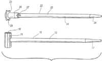
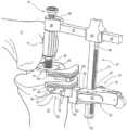
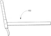
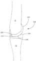
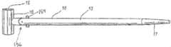
示される実施形態において、組立体10は、この場合には90°の屈曲である屈曲位にある膝で組立体10の残りを支持するための基準点を提供する2つのIMロッド、すなわち大腿骨IMロッド13および脛骨IMロッド14を含む。図1に示されるように、大腿骨IMロッド13は、大腿骨マウント15と、主シャフト16と、を含む。図2に示されるように、大腿骨IMロッド13の主シャフト16は、好ましくは、設置されるときに、大腿骨11のIM管内で近位-遠位方向に延在する、細長い比較的剛性のシャフトである。主シャフト16は、先細の端部17などの、大腿骨11内への挿入を容易にする構造を含むことができる。好ましくは、主シャフト16は、硬質プラスチック、ステンレス鋼、チタン、または他の金属などの相対的に剛性の材料、あるいは損傷することなく骨の中に挿入し、大腿骨マウント15を安定して支持することができる材料で構成される。In the embodiment shown, the
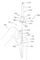
大腿骨マウント15は、先細の端部17とは反対側にある主シャフト16の遠位端に取り付けられる。一般に、大腿骨マウントは、主シャフト16の長軸線に対して垂直に延在する軸線を有する円筒形状を有する。図3の大腿骨マウントの断面図で示されるように、中央開口部18が、大腿骨マウント15の軸線に沿って画定される。以下で詳細に記載されるように、中央開口部は、組立体10の他のコンポーネントを大腿骨マウント15に係止するのを可能にする2つの部分、すなわち本例では六角形の部分である回転防止部分19および円筒形部分20を含む。それにも関わらず、大腿骨IMロッド13が設置されると、大腿骨マウント15およびその中央開口部18は、好ましくは、大腿骨顆の間の大腿骨切り欠きに沿って前方-後方方向に延在する。以下で詳細に記載されるように、脛骨および大腿骨コンポーネントの位置決めを助ける長手方向に延在する複数のゲージマーク21が、大腿骨マウント15の円筒形の外面上に画定される。The
図1および図4に示されるように、脛骨IMロッド14は、脛骨マウント23を支持する主シャフト22を含む。大腿骨IMロッド13の主シャフト16と同様に、主シャフト22は、それを脛骨のIM管内に挿入するのを容易にするために、先細の遠位端24を有する細長い構造を有する。しかしながら、主シャフト22は、好ましくは、挿入をさらに容易にするために、および脛骨がIM管内で回転するのに抵抗するために、その全長に沿って延在する1つ以上の溝25を含む。これらの溝は、随意に、主シャフト16上に含まれてもよい。溝25内に延在する開口部27が、その近位端において主シャフト22内に画定される。これらの開口部は、脛骨をIM管内に挿入するのをさらに容易にする。大腿骨IMロッド13の主シャフト16と同様に、主シャフト22は、脛骨マウント23のためのしっかりした支持を提供するように、相対的に剛性の材料の範囲で構成されてもよい。本発明のいくつかの実施形態では、脛骨IMロッドの主シャフト22は、脛骨の上面の開口部と係合するための短い伸長部を形成するように切頭されている。したがって、脛骨IM管に接近するのではなく、脛骨マウント23および切頭された脛骨IMロッドが主に、脛骨の外面と係合および接触する。他の実施形態では、脛骨マウント23の平坦な表面が脛骨の切除表面に直接着座するように、脛骨マウント23は、脛骨IMロッドなしで提供される。したがって、脛骨マウント23と脛骨との間の界面は、完全に骨髄外である。これらの実施形態では、脛骨に対する脛骨マウント23の位置は、脛骨マウント23と脛骨との間の垂直方向の圧縮力によって維持される。他の実施形態では、脛骨マウント23の平坦な表面は、引張している間の脛骨マウントコンポーネント23の望ましくない移動を防ぐために、切除された脛骨表面とさらに接触する複数のスパイクを含むように変更される。As shown in FIGS. 1 and 4, the
図4に示されるように、厚くなった円筒形部分26およびプラトーフランジ28が、脛骨マウント23内に含まれる。円筒形部分26は、好ましくは、脛骨12のIM管に適合するようなサイズにされる。円筒形部分は、その遠位端において主シャフト22に接続され、近位端においてプラトーフランジ28を支持する。プラトーフランジは、円筒形部分26から直角に外方に延在し、3つの平坦な側面と、1つの三日月形状の側面と、を有する。三日月形状の側面は、近位脛骨の切除の前に、前十字靭帯のために空間を提供するための切り取り部である。平坦な側面は、単一の顆、および脛骨プラトーの一部分だけを再構成する片側関節形成術処置における脛骨区画の切除の際などに、位置決めおよび切断を誘導するのをさらに助けることができる。As shown in FIG. 4, a thickened
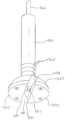
図5および図6に示されるように、ねじ切られた開口部29が、脛骨マウント23内に延在し、ねじ山付きシャフト31と、六角形フランジ32と、ブッシング33と、を含む屈曲ボルト30のための連結取り付け部を提供する。ねじ山付きシャフト31は、複数のねじ山を有し、六角形フランジ32から離れるように延在する一方で、ブッシング33は、六角形フランジ32の他方の側からねじ山付きシャフトの反対側に延在する平滑な円筒形シャフトである。六角形フランジ32は、ねじ山付きシャフト32の前進のための原動力を提供するために、トルクまたは他のレンチによって把持するのを可能にするような形状にされる。As shown in Figures 5 and 6, a threaded opening 29 extends into the
図5に示されるように、ねじ山付きシャフト31は、これがプラトーフランジ28と同一平面になり、これによってブッシング33が最も低い外形位置に位置決めされるまで、脛骨マウント23のねじ切られた開口部29内に前進されるように構成される。この位置により、大腿骨11、およびそこから延在する大腿骨マウント15は、ブッシング33の上方の位置に滑り込むことが可能になる。次に、図7に示されるように、トルクレンチを使用して、ブッシング33が大腿骨マウント15内の中央開口部18の円筒形部分20に係合するまで、ねじ山付きシャフト31の前進を逆にする。トルクレンチにおいて予め選択されたトルク測定値を達成するまで、または十分な靭帯構造の張力が得られるまで、前進が逆にされる。適切な靭帯張力が得られると、本技術において後に比較するために、このトルク値が記録される。結果として得られる組立体は、(例えば、30°、60°、もしくは90°の屈曲の、またはその間の増分)屈曲位の膝での大腿骨および脛骨の静的連結に匹敵し、以下に記載されるように、外科医は、ここから後の切除器具を参照することができる。As shown in FIG. 5, the threaded
図8および図9に示されるように、組立体10にはまた、中央開口部18の六角形部分19内に接続する迅速接続係止機構34も含まれる。係止機構のこの実施形態には、静的張り出しアーム35と、ばね付勢式プランジャ36と、回転防止特徴部19に匹敵し、本例では六角形状を有する静的クロッキング伸長部37が含まれる。アーム35は、細長い部分38と、丸いヘッド部分39と、を有する。アーム35の細長い部分38は、正方形の断面を有し、その両端部に一対の対向する平坦部を有する、部分的に円筒形状を有する丸いヘッド部分39から延在する。六角形伸長部37は、丸いヘッド部分の平坦部の一方から延在する。六角形伸長部37は、大腿骨マウント15内に画定された中央開口部18の六角形部分19内にぴったりと適合するように構成された六角形の断面を有する。図8に示されるように、以下に記載されるように、プランジャ36の運動を誘導する螺旋状に延在するスロット43が、ヘッド部分39の1つの丸い表面内に画定される。8 and 9, the
プランジャ36が通って延在する円筒形開口部40が、丸いヘッド部分39および六角形伸長部37を通って画定される。特に、プランジャ36は、親指プレス41と、シャフト42と、ばね45と、本例では六角形であるが、回転を制限することができる正方形、三角形、または楕円などの任意の非円筒形状とすることができる回転防止特徴部37に匹敵する回転伸長部44と、を含む。親指プレス41は、プランジャ36の一端に位置決めされ、親指での押し下げを促進するための隆起部を有する円板形状である。好ましくは、コイル形状であり、シャフト42の周りに、親指プレスとヘッド部分39との間に延在し、これらを離れるように付勢するばね45が、親指プレス41の下にある。A
図8に示されるように、シャフト42は、シャフトに対して垂直に、ヘッド部分39内に画定された螺旋状スロット43内に延在するペグ46を含む。したがって、親指プレス41を押し下げることによって、シャフト42がヘッド部分39の開口部40内に前進され、またそこに固定されたペグ46が、螺旋状スロット43内に螺旋状に進行するにつれて、シャフトの回転ももたらす。プランジャ36の六角形端部44は、親指プレス41とは反対側にあるシャフト42の端部に固定され、六角形伸長部37の自由端に沿って延在し、六角形伸長部37のものと合致する六角形状およびサイズを有する。As shown in FIG. 8, the
図10に示されるように、シャフト42に接続することに起因して、親指プレス41を押し下げることにより、六角形端部の平坦部が六角形伸長部37の平坦部の配向に合致するまで、プランジャ36の六角形端部44も回転させられる。図11に示されるように、このように配向を合致させることにより、六角形伸長部37および六角形端部44を大腿骨マウント15の中央開口部18の六角形部分19内に挿入することが可能になる。親指プレス41が解除されると、ばね45は、親指プレス、シャフト42、および六角形端部44を上方に付勢し、六角形端部の平坦部を、六角形伸長部37の平坦部に対して合致しない、位相のずれた位置(図9に示される)に戻す。As shown in FIG. 10, by connecting to the
この時点で、プランジャ36の六角形端部44は、中央開口部18の円筒形部分20内に存在し、その合致しない位置により、中央開口部の六角形部分19を通して引き抜くことができない。結果として、係止機構34は、回転し、かつ並進させることにより大腿骨マウント15および大腿骨IMロッド13に対して係止された状態になる。一旦適所に係止されると、係止機構34のアーム35は、大腿骨マウント15および大腿骨11の顆から前方外方に延在する。とりわけ、比較的狭い大腿骨マウント15とアーム35の狭く細長い構造との組み合わせは、比較的小さい外科的アプローチの開口部の通過を可能にし、より非侵襲的処置による組立体10の使用を容易にする。例えば、変更された中間広筋、内側中間広筋、または副広筋アプローチは、前脛骨からの四頭筋の剥離を回避することを可能にする8~10cmの小さい切断部と共に使用され得る。At this point, the
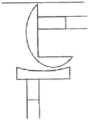
本発明の示される実施形態の組立体10にはまた、係止機構34によって支持される屈曲ガイド支持部材47も含まれる。摺動部材48と、ラチェットバー49とが、屈曲ガイド支持部材に含まれる。摺動部材は、摺動部材が係止機構34のアーム35の矩形断面によって支持され、これに沿って摺動することを可能にするサイズおよび形状にされた矩形開口50を画定する。この運動によって、摺動部材48に取り付けられているラチェットバー49が、膝関節に向かって、および膝関節から離れるように移動することが可能になる。摺動部材48は、好ましくは、指グリップ(例えば、図示された摺動部材の先細の部分)を有するような形状にされ、アーム35に対して抵抗するが、その摺動を妨げないように、いくつかのタイプのピンまたは係止組立体を含んでもよい。図12に示されるように、ラチェットバー49自体の断面も矩形形状であり、組み立てられたときに、係止機構34のアーム35から遠位方向に延在する。ラチェットバー49はまた、ラチェットバーの全長に沿って延在する隣接した複数のラチェット溝51を支持する、一対の面取りされたコーナー部を含む。The
図13、図14、および図15に示されるように、組立体10はまた、屈曲ガイド支持部材47に取り付けられる屈曲膝切断ガイド組立体52を含む。屈曲膝切断ガイド組立体52は、迅速解除機構53と、切断ガイド54と、を含む。迅速解除機構53は、本体55と、延伸ピン56と、第1および第2のばね57、58と、係止レバー59と、係止ピン60と、を含む。図16に示されるように、本体55は、本体が、ラチェットバー49の矩形断面の上に摺動されることを可能にする矩形開口部61を画定する。さらに、本体55は、延伸ピン56の端部がラチェット溝51に係合するように、延伸ピン56が延在する側部開口部を含む。特に、第1のばね57は、延伸ピンを、よって、本体55を摺動部材48上の特定の位置に係止するように、ラチェット溝に正常に係合する位置に延伸ピンを付勢する。係止ピン60は、本体および延伸ピン56を通って延在して、延伸ピン56を固定し、これが分解されるのを防ぐ。13, 14, and 15, the
本体55は、付加的に、延伸ピン56とは本体の反対にある側から外方に延在し、その中間部分を中心とする係止レバー59の回転をサポートするクレビス62を含む。図17によく示されるように、係止レバーは、第2のばね58によって本体55から外方に付勢された湾曲した指グリップを有し、係止レバーの反対側の端部は、以下に記載されるように、切断ガイド54に係合し、迅速解除機構53をそこに係止する先細の舌部63を含む。本体55の係合部材64が、係止レバーの反対側に、クレビス62から離れるように延在する。係合部材64は、矩形断面を有し、図13に示されるように、組み立てられた状態では、切断ガイド54との接続部内に延在する。The body 55 additionally includes a
図13に示されるように、切断ガイド54は、(組み立てられたとき)迅速解除機構53から後方に延在し、装着部分65と、kワイヤガイドまたは固定ピン部分66と、横ピン部分71と、近位脛骨切断ガイド部分67と、後顆大腿骨切断ガイド部分68と、を含む。装着部分65は、迅速解除機構53の本体55の係合部材64を摺動可能に受容するようなサイズおよび形状にされた矩形開口部69を画定する。図18に示されるように、装着部分65はまた、矩形開口部69の側壁のうちの1つの中に切り欠き70を画定する。図15に示されるように、係止レバーが、第2のばね58の付勢下にあるときに、切り欠き70は、係止レバー59の先細の舌部63を受容するようなサイズおよび形状にされ、かつそのために位置決めされる。係止レバー59の自由端を押し下げることによって、切断ガイド54の解除が容易に達成され、第2のばね58の付勢を克服し、装着部分65の切り欠き70から先細の舌部を分離する。As shown in FIG. 13, the cutting guide 54 extends posteriorly from the quick release mechanism 53 (when assembled) and includes a mounting portion 65, a k-wire guide or fixation pin portion 66, a transverse pin portion 71, a proximal tibial cutting
図13に示されるように、固定ピン(または、kワイヤ)ガイド部分66、脛骨切断ガイド部分67、および大腿骨切断ガイド部分68は各々、(どの切断が行われるかによって)前内脛骨または前外脛骨の解剖学的湾曲部の周りに内側-外側方向に延在する三日月形状を有する。固定ピンガイド部分66は、装着部分65に隣接しており、(組立体10の他のコンポーネントを解除する前に、切断ガイド54を固定するために使用される)固定ピンを、脛骨12上の皮質骨の最も厚い前方部分に誘導するような角度で後方に延在する複数の固定ピン穴72を画定する。あまり好ましくはないが、固定ピン穴の数および配向は、所望の接続の強固さ、脛骨12のサイズおよび形態などによって変えることができる。As shown in FIG. 13, the fixation pin (or k-wire) guide portion 66, the tibial cutting
脛骨切断ガイド部分67は、固定ピンガイド部分66に隣接して位置決めされ、かつ脛骨切断を誘導するためのスロットを画定する。スロットは、ガイド部分67の三日月形状の全長に沿って延在し、一般に、脛骨プラトーに対して平行な配向を有する。しかしながら、ガイド部分67によって画定される切除平面は、所望の位置および切断ガイド54についての外科医の好みに応じて、後方スロープ(矢状平面の傾斜度)、および内反/外反(前頭平面の傾斜度)において変わり得る。こうした切断の例が、図19に示され、ここで、脛骨は、脛骨12の近位端において前方-後方および内側-外側の平面に延在する平坦な平面の切断部を有する。大腿骨切断ガイド部分68は、膝関節区画を架橋するように、一対の接続用フランジ73によって、脛骨切断ガイド部分67から近位方向に離間配置される。脛骨切断ガイド部分67と同様に、大腿骨切断ガイド部分68は、三日月形状の全長に沿って延在するスロットを画定する。しかしながら、膝は屈曲位にあるので、切断は、大腿骨11の顆の後方を通って誘導される。The tibial cutting
大腿骨マウント15と、脛骨マウント23と、屈曲ボルト30と、係止機構34と、屈曲ガイド支持部材47と、屈曲膝切断ガイド組立体52と、を含む、屈曲位の膝に対する切断部の位置決めのための組立体10のコンポーネントの利点は、膝の前方軟組織において、比較的非侵襲的な狭い切断部による(および、後退した膝蓋骨による)それらの有用性である。一般に、図14および図15に見られるように、膝の屈曲位で切断を行うための組み立てられたコンポーネントは、それらがU形状の関節空間の外に延在するので、比較的狭い一方で、同時に、切断ガイド54を支持するための安定した接続、コンポーネントの迅速な組み立ておよび解除、ならびに屈曲膝切断ガイドの正確な位置決めを提供する。(皮膜切開の内側に位置決めすることができる)切断ガイド54自体を考慮すると、このコンポーネントの幅は、例えば、最大で4~5cmまでの範囲内の従来の切断ガイドと比較すると小さいものであり、これによって膝関節への低侵襲性アプローチによるそれらの使用が可能になる。The advantage of the components of the
図19~図29に示されるように、組立体10はまた、伸長位の膝(すなわち、一般に、位置合わせされた脛骨および大腿骨すなわち0°の屈曲)に対する切断を誘導するように構成された器具も含む。図19に示されるように、膝の伸長のために、大腿骨IMロッド13および脛骨IMロッド14の両方は、適所にあるままである。しかしながら、脛骨マウント23に脛骨IMロッド14を取り付ける代わりに、脛骨角形成ガイド74が、脛骨IMロッドに取り付けられる。脛骨角形成ガイド74は、ゲージブロック76と、(屈曲ボルト30と同様であるが、ブッシング33を有していない)伸長ボルト96内に適合する支柱97と、を含む。伸長ボルト96はまた、六角形フランジ75も有する。あるいは、ブッシング33内の開口部内に延在するシャフト(図6に示されるような)と共に、別個のゲージブロック76を用いてもよく、ボルト30が外れるのを回避することを可能にする。As shown in Figs. 19-29, the
それにもかかわらず、図19~図21に示されるように、伸長ボルト96のねじ山付きシャフトがねじ切られた開口部29内に延在するときに、ゲージブロック76は、脛骨マウント23のプラトーフランジ28から上方に延在し、かつ、弧状面77、およびその前方表面に画定された複数のゲージマーク78を画定する。弧状面77は、円筒形状の大腿骨マウント15の外面を受容するような形状およびサイズにされ、大腿骨マウント15が、内反-外反方向に回転し、内部で前方-後方方向に摺動することを可能にする。これらの運動は、大腿骨11および脛骨12を過度に抑制しないように自由に任されるが、脛骨および大腿骨切断のより良い位置決めのために、依然として器具の前方-後方方向の位置合わせおよび回転位置の選択を促進する。ゲージブロック76(円筒形状を有する)および大腿骨マウント15(弧形状を有する)の形状を逆にすること、2つのプレート間に丸い形状を有すること、角形成読み取り値を器具組立体から離れるように延在させることなどによって、これらの運動範囲を可能にするように、大腿骨マウント15および脛骨角形成ガイド74の形状の他の変形形態および組み合わせを用いることができ、依然として本発明の範囲内である。19-21, when the threaded shaft of the extension bolt 96 extends into the threaded opening 29, the
トルクレンチによる伸長ボルト96の六角形フランジ75の回転を調節することによって、屈曲位置における技術と同様に、大腿骨11および脛骨12の相対的な近位-遠位の位置決めの調節が達成される。この運動は、脛骨伸長ボルト96のねじ山付きシャフトを、脛骨マウント23内のねじ切られた開口部29内に、またはそこから前進させるか、または後退させ、かつ脛骨角形成ガイド74を大腿骨マウント15に前進させる。好ましくは、関節が膝の伸長位において過度に締め付けられないことを保証するために、トルクレンチが屈曲位の膝に関するものと同様の読み取り値を有するまで、大腿骨11および脛骨12は、伸延される。トルクレンチおよび関節空間の量に関して、レンチの全長に延在し、その端部に六角形状のジョーを有し、比較的薄い、すなわち薄型の伸長装置が、トルクレンチに装備されてもよい。この場合には、伸長装置の付加的な長さを補償するように、トルク測定値が、調節されてもよい。いずれの場合でも、目的は、器具の構成が、膝をある程度の屈曲、すなわち本例では90°の屈曲、またはそれらの間の増分で拘束したときに得られるトルク値に合致させこと、および以前のステップにおいてトルクレンチにおいて達成された同様のトルク測定値まで、または十分な張力の靭帯構造が得られるまで、ボルトにトルクを与えることである。By adjusting the rotation of the hexagonal flange 75 of the extension bolt 96 with the torque wrench, adjustment of the relative proximal-distal positioning of the
再び図20および図21を参照すると、ゲージブロック76のゲージマーク78は、大腿骨マウント15の回転の中心から外方に放射状に広がり、大腿骨マウントの外面から始まり、ゲージブロックの前方表面上に位置決めされる。ゲージブロック76のゲージマーク78は、大腿骨マウント15のゲージマーク21(矢印で示されるような)と調和して、大腿骨11に対する脛骨12の外反角を指示するように構成される。一般に、外反角は、膝の形態、外科医の好みなどによって、3~7度まで、またはさらに2~9度までの範囲内にすべきである。20 and 21, the gauge marks 78 of the
図22および図23に示されるように、一旦大腿骨11に対する脛骨12の角形成および近位-遠位の位置決めが調節されると、伸長ガイド支持部材79は、第2の係止機構84を使用して大腿骨マウント15に取り付けられる。一般に、第2の係止機構84は、第1の係止機構34の同じコンポーネントと同様の機能を共有することから同様に番号付けされた、プランジャ36(および、六角形端部44を含むそのコンポーネント)と、六角形伸長部37と、螺旋状スロット43と、を含む。第2の係止機構84は、ヘッド部分39がいくらかより長く、円筒形であり、アーム35の細長い部分38がないという点で異なる。また、第2の係止機構84は、プランジャを押し下げるときに、指で把持するのを容易にするために、プランジャ36に隣接して位置決めされた把持フランジ86を含む。それには関係なく、六角形端部44は、第2の係止機構84の端部の大腿骨マウント15への迅速な取り付けを容易にする同じ回転運動を有する。22 and 23, once the angulation and proximal-distal positioning of the
伸長ガイド支持部材79は、装着部分80と、支持アーム81と、固定フランジ82と、を含む。装着部分80は、第2の係止機構84を摺動可能に受容するように構成されるが、前述の第2の係止機構84により回転が制限されない、そこを通って延在する円筒形開口部83を有する円筒形状を有する。T形状の断面を有する細長い構造である支持アーム81が、装着部分80の一方の側から離れるように延在する。この場合ボールおよびばね85である機構のためのハウジングとして働く付加的なフランジ82は、装着部分80の他方の側から離れるように延伸しており、第2の係止機構84に対する伸長ガイド支持部材79の回転にいくらかの抵抗を提供する。The elongated guide support member 79 includes a mounting portion 80, a
図24~図29に示されるように、位置決めの間、伸長ガイド支持部材79によって支持される伸長膝切断ガイド87もまた、組立体10の示される実施形態に含まれる。伸長膝切断ガイド87は、装着部分88と、固定ピン(またはkワイヤ)ガイド部分89と、大腿骨切断ガイド部分90と、基準レバー91と、を含む。装着部分88は、一般に、伸長膝切断ガイド87の本体部分の中央に配置され、支持アーム81のT形状の断面に合致する断面形状を有するチャネル92を画定する。合致する形状により、伸長膝切断ガイド87が、支持アーム81に沿って近位-遠位方向に摺動することが可能になる。Also included in the illustrated embodiment of the
固定ピンガイド部分89は、伸長膝切断ガイド87の位置決め後、固定ピンを使用した固定を可能にする、複数のkワイヤ(または例えば、ねじ、釘などの他の種類の締結具)穴93を画定する。図25に示されるように、穴93は、比較的厚い皮質骨に固定するのを可能にするように位置決めされるときに、前大腿骨の内側および外側側部に位置決めされる。kワイヤ穴72と同様に、kワイヤ穴93は、大腿骨11上のより密度の高い骨の中に、かつ、より長い長さを通して締結具を誘導するように、様々な角度で配向されるか、または選択的に位置決めされ得る。The fixation pin guide portion 89 defines a number of k-wire (or other types of fasteners, e.g., screws, nails, etc.) holes 93 that allow for fixation using fixation pins after positioning of the extended
大腿骨切断ガイド部分90は、(示される実施形態と同様に)片側の再構成のために内側または外側のいずれかに延在するか、または大腿骨顆の完全な切除のために両方の方向に延在する。とりわけ、図29によく示されるように、ガイド部分90は、伸長膝切断ガイド87が適所にあるときに、第2の係止機構84の周りに適合するUの形状に遠位方向に延在する。それとは関係なく、ガイド部分90は、kワイヤガイド部分89から遠位方向に延在し、次に、外側方向にまたは内側方向に延在して、ガイドスロット94を画定する。ガイドスロット94は、切断器具または切刃の通過を可能にするのに十分な幅を有するが、依然として、相対的に真っ直ぐなまたは平面的な切除を促進する。とりわけ、内側への伸長は、膝関節区画への内側に配向されたアプローチにおいて、外側に移動した膝蓋骨を回避することを可能にする。The femoral cutting guide portion 90 extends either medially or laterally for unilateral reconstruction (as in the embodiment shown), or in both directions for complete resection of the femoral condyle. As best seen in FIG. 29, among other things, the guide portion 90 extends distally in a U-shape that fits around the second locking mechanism 84 when the extended
基準レバー91を回転可能に支持するクレビス95を画定する伸長膝切断ガイド87の一部分が、大腿骨切断ガイド部分90から遠位方向にさらに延在する。図24および図25に示されるように、基準レバーは、外側または内側方向に延在し、前方-後方方向に回転して、関節区画における位置決めを可能にする。基準レバー91は、平坦な脛骨の切断部に載置されるように構成されている広く平坦な遠位面を有し、平坦な外側表面は、プラトーフランジ28の側面に当接するように構成される。これらの表面は、伸長ガイド支持部材79の支持アーム81に沿った、伸長膝切断ガイド87の遠位方向の移動に対する止め部を提供する。基準レバー91および第2の係止機構84が適所にあるときに、固定ピンは、ガイド部分89内のピン穴93を通って挿入されて、大腿骨切断ガイド部分90を大腿骨11に固定することができる。図27、図28、および図29に示されるように、このことは、伸長ガイド支持部材79の除去を可能にする。Extending further distally from the femoral cutting guide portion 90 is a portion of the extended
有利なことに、伸長ボルト96と、脛骨角形成ガイド74と、伸長ガイド支持部材79と、伸長膝切断ガイド87と、を含む、伸長位にある膝に対する切断の位置決めのためのコンポーネントは、コンポーネントの狭い幅および外形のために、膝区画への前方および内側のアプローチを通過するように構成される。例えば、図25に示されるように、第2の係止機構84の後方部分および基準レバー91は、切開部を通過し、前述の狭さと薄型を呈するであろう。好ましくは、このコンポーネントの幅は、例えば、最大で4~5cmまでの範囲内の従来の切断ガイドと比べて小さく、これによって膝関節への低侵襲性アプローチと共に使用することが可能になる。Advantageously, the components for positioning the cut on the knee in extension, including the extension bolt 96, the
これらの最初の切断の後、最初の切断部を基準として使用して、次に、さらなる切断を行うことができる。図30および図31に示されるように、L形プレート99を用いて、大腿骨11の後方および遠位方向の平坦な表面に当接させて、前方切断を誘導する。面取り切断ブロックを使用して、(前方および後方の)面取り切断を行うことができ、他の仕上げ切断は、本発明の組立体10を使用して行われる最初の切断部を基準にすることができる。これらの仕上げ切断のさらなる説明は、参照により本明細書に組み込まれる、2004年3月5日に出願された「Reference Mark Adjustment Mechanism for a Femoral Caliper and Method of Using the Same」と題する米国特許出願第10/794,188号に見出すことができる。After these initial cuts, further cuts can then be made using the initial cuts as a reference. As shown in Figures 30 and 31, an L-shaped plate 99 is used to abut against the posterior and distal flat surfaces of the
図32~図40に示されるように、本発明の別の実施形態では、組立体10は、迅速な組み立てを促進するための、付加的なモジュール式オプションを含む。図32に示されるように、大腿骨IMロッド13は、二次的大腿骨マウント100を含む。二次的大腿骨マウント100は、中央取り付け部から大腿骨IMロッド13の主シャフト16の遠位端まで外側および遠位方向に延在するサドル形状または三日月形状を有する。図33に示されるように、大腿骨マウント15を支持する大腿骨マウントロッド102を受容するように構成されている開口部101が、サドルの内部の凸状湾曲面内に画定される。As shown in Figures 32-40, in another embodiment of the present invention, the
再び図32を参照すると、脛骨IMロッド14は、シャフト22によって支持される変更されたバージョンの脛骨マウント23を含む。特に、脛骨マウント23のプラトーフランジ28は、ねじ切られた開口部29から外側外方に延在する拡大した矩形形状を有する。プラトーフランジ内に後方に延在する一対のガイドマウント用開口部103が、プラトーフランジ28の前方側部で画定される。図34に示されるように、屈曲ボルト30は、ヘッド105から延在するねじ山付きシャフト31を含む六角形ヘッドボルト105内に画定された中央開口部内にブッシング33および六角形フランジ32を装着するための支柱104を提供することによって、さらにモジュール化されてもよい。図35および図36は、六角形ヘッドボルト105の高さによる締め付けの調節と共に、大腿骨マウント15および脛骨マウント32の組み立てを示す。Referring again to FIG. 32, the
図37に示されるように、組立体10はまた、屈曲膝切断ガイド54と、直接型マウント106と、を含む、屈曲膝切断ガイド組立体52も含む。直接型マウントは、離間配置され、かつ装着ブロック108から延在する一対の支柱107を含む。支柱107の間隔およびサイズは、プラトーフランジ28内に画定されたガイドマウント開口部103内に延在するように構成される。装着ブロック108は、密閉して封止された磁石111などによって、脛骨マウント32に連結され得る。屈曲膝切断ガイド54は、装着ブロック108に取り付けられ、そこから遠位方向に延在する。屈曲膝切断ガイドは、脛骨および大腿骨の切断を誘導するための一連のスロット109を画定する。37, the
屈曲膝切断ガイド組立体52を、上下反対に回すことによって、または上下反対の切断ガイド組立体52の変更であるであろう別のブロックを使用することによって、後大腿骨の切断を達成することができ、ここで切断ガイド54および一連のスロット109は、支柱107に向かって、したがって、膝の後大腿骨顆のより近くに移動される。切断ガイド組立体52の一連のスロット109は、スロットが中央に取り付けられた状態で示されるか、または、中央が開口しており、切断ガイド54の両側に沿って取り付けることもできる。The posterior femoral cut can be accomplished by turning the flexed knee cutting guide assembly 52 upside down, or by using another block that would be a modification of the upside down cutting guide assembly 52, where the cutting guide 54 and series of slots 109 are moved toward the post 107 and therefore closer to the posterior femoral condyles of the knee. The series of slots 109 of the cutting guide assembly 52 are shown with the slots mounted in the center, or they can be open in the center and mounted along both sides of the cutting guide 54.
図38および図39に示されるように、脛骨IMロッド14はまた、外反アダプタ部材110、または六角形ヘッドボルト105の中央開口部内に挿入するように構成されている、それぞれの支柱を有する大腿骨マウント15の変更されたバージョンを含んでもよい。図40に示されるように、外反アダプタ部材110は、二次的大腿骨マウント100の窪み形状内に延在するように構成された凸形状を有する。上記に開示された第1の実施形態と同様に、この合致により、膝が伸長位にあるときに、内反-外反角形成が切断部を位置決めすることを可能にする。支柱107を介する屈曲膝切断ガイドと同様に、伸長膝切断ガイドが装着され得る。38 and 39, the
本発明の組立体10は、多くの利点を有する。それは、切断ガイドを脛骨および/または大腿骨のIMロッドに確実に取り付ける、係止コンポーネントの比較的狭く薄型の集合体を提供する。このことは、侵襲性を最小化する関節へのアプローチを用いて、脛骨および大腿骨に対して行われる基準切断に対して、頑丈なガイドを提供する。さらに、第1および第2の係止機構34、84、ならびに迅速解除機構53などの多くのコンポーネントは、効率の向上のために、迅速な組み立て、簡単な調節、および迅速な分解を容易にする。ボルト30および96もしくは105、ならびに脛骨角形成ガイド74、または外反アダプタ部材110を使用することにより、屈曲位および伸長位における合致する量のトルクのもとで、脛骨および大腿骨を伸延させることが可能になり、屈曲範囲全体にわたって脛骨および大腿骨の膝置換コンポーネントをより良好に適合させることが確実になる。また、脛骨角形成ガイドにより、外科医が、患者の解剖学的構造と合致させるのに所望されるように、脛骨の外反角形成の量を調節することが可能になる。The
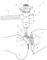
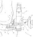
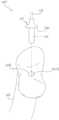
図41に示されるように、本発明の別の実施形態では、変更された大腿骨マウントロッド102およびマウント15を大腿骨マウントロッド102に取り付けるヒンジ機構を有する大腿骨マウント15を、大腿骨マウント15内の穴18を通して配置された開創器ロッドと共に使用し、脛骨に向けて後方に誘導し、これにより、骨の切断が行われた後に、開創器が脛骨を前部または前方に変位させて、膝関節全置換術の脛骨コンポーネントを配置するための露出を可能にするために、支持台およびレバーアームを提供する。IMロッドは骨に堅固に固定されるので、膝の手術の間、膝の露出を容易にするために、他の開創器をガイド組立体に取り付けることもできる。As shown in FIG. 41, in another embodiment of the present invention, a modified
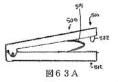
図42Aに示されるように、本発明の別の実施形態では、実際の膝関節形成術インプラントより小さいが、同一の(または実質的に同一の)厚さおよび半径を有するような形状にされ、大腿骨IMロッド13の穴101および脛骨IMロッド14の穴29に適合し、膝の中央部分において関節をなすように設計された小型のトライアルコンポーネントまたはトライアルコンポーネントを使用して、実際の最終的な膝関節形成術インプラントを配置する前に、位置合わせおよび靭帯の安定性を確認することができる。小型の膝関節形成術インプラントシステムを中央に配置したこの設計は、独立型の膝関節全置換術になる。本発明の本実施形態の1つの利点は、小さい器具はあまり場所をとらないということである。小型のトライアル大腿骨コンポーネントは、面取り切断、および他の仕上げ切断を行うための切断表面またはスロットと共に設計され得、したがって、図30および図31に示される面取り切断ブロックおよびL形プレート99に対する必要性がなくなる。As shown in FIG. 42A, in another embodiment of the present invention, a small trial component or trial components shaped to be smaller than the actual knee arthroplasty implant but have the same (or substantially the same) thickness and radius, fit the
さらに、そのようなトライアルコンポーネントは、任意の好適なコンポーネントまたは特性を含むことができるが、図42B~図42Eは、いくつかの実施形態では、トレイル大腿骨インプラント600がトライアル脛骨コンポーネント602の窪み面または凹面に対して関節運動するように構成されている凸状の丸い表面を含むことを示す。さらに、いくつかの実施形態では、トライアル脛骨コンポーネントおよびトライアル大腿骨コンポーネントのうちの1つ以上のコンポーネントは、大腿骨と脛骨との間の間隙を変化させるために任意の好適な調節機構によって選択的に(例えば、遠位方向に、後方に、および/またはそれ以外の方向に)調節可能である。Furthermore, while such trial components can include any suitable components or features, FIGS. 42B-42E show that in some embodiments, the trail
さらに、そのようなトライアルコンポーネント(中央に配置された間隙バランサおよび/またはスペーサ)は、非限定的に、以下で考察されるスペーサ500を含む、本明細書に記載された任意の他の好適なコンポーネントと共に使用され得る。Furthermore, such trial components (centrally located gap balancers and/or spacers) may be used with any other suitable components described herein, including, without limitation, the
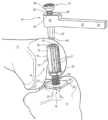
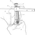
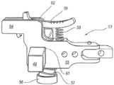
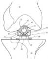
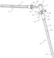
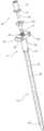
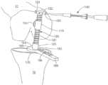
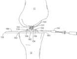
ここで図43~図48を参照すると、本発明の別の実施形態が示される。具体的には、図43~図45は、屈曲位にある患者の膝を切除するための本発明の実装形態を示し、図46~図48は、伸長位にある患者の膝を切除するための本発明の実装形態を示す。各実施形態の大腿骨IMロッド113の大腿骨マウント150は、実質的に嵌め込まれており、大腿骨11の挿入部位と同一平面上にある平面のフランジを含む。一実施形態では、骨鉗子を使用して、3/8インチのドリル入口のために遠位大腿骨を準備する。ドリルを挿入した後、次に、平面を使用して残りの骨を挿入部位から取り除き、大腿骨マウント150が着座する凹面を提供する。図46および図47に示されるように、ねじ切りされた開口部129は、大腿骨マウント150内に延在し、ねじ山付きシャフト131と、装着穴133を有する円形フランジ132と、中央に配置されたボール134と、を含む伸長ボルト130のための連結取り付け部を提供する。さらに、ねじ切りされた開口部129は、ねじ山付き胴部115のねじ山なし支柱114が挿入される装着チャネルを提供する。ねじ山なし支柱114とねじ切りされた開口部129との間の相互作用は、ねじ山付き胴部115を大腿骨IMロッド113内に十分に保持し、IMロッド113に対するねじ山付き胴部115の軸方向の回転を可能にする。軸の回転は、患者の膝の自然な生理機能に対して外科用工具の制限された移動を許容するために望ましい。したがって、ねじ山付き胴部115は、以下に記載されるように、回転し、引張突起を通る患者の膝の自然な位置合わせを容易にすることが許容される。43-48, another embodiment of the present invention is shown. Specifically, FIGS. 43-45 show an implementation of the present invention for resecting a patient's knee in a flexed position, and FIGS. 46-48 show an implementation of the present invention for resecting a patient's knee in an extended position. The
ねじ山付き胴部115は、ねじ山付き開口部116の外面に垂直に連結されたねじ山なし支柱114を含む。ねじ切りされた開口部116は、ねじ山付き胴部15を貫通して延在し、屈曲ボルト120のための連結取り付け部を提供する。屈曲ボルト120は、ねじ山付きシャフト121と、装着穴123を有する円形フランジ122と、ねじ山なし先端部124と、を含む。ねじ山付きシャフト121は、ねじ山なし先端部124がねじ山付き胴部115を出て、それを越えて延在するように、ねじ山付き開口部116を通って適合的にねじ込まれる。円形フランジ122は、ねじ山なし先端部124とは反対側にあるねじ山付きシャフト121に垂直に取り付けられる。フランジ122は、円形であり、フランジ122の周縁部の周りに等間隔に配置された複数の装着穴123を有する概ね円板形状である。装着穴123は、屈曲ボルト120を回すためのトルクレンチ140または他のデバイスを適合的に受容するようなサイズおよび構成にされる。いくつかの実施形態によれば(例えば、図43および図44に示されるように)、膝が屈曲位にあるときに脛骨および大腿骨が互いに対して引張されていると、記載されたデバイスは、膝関節の内反-外反角形成の変化を可能にする。The threaded
本実施形態は、脛骨引張アダプタ160をさらに含む。脛骨引張アダプタ160は、脛骨IMロッド170によって安定的に支持され、脛骨IMロッド170の主シャフトに対して概ね垂直に位置決めされる。脛骨引張アダプタ160は、ベース部材161と、切除ブロックガイド165と、を含む。ベース部材161は、概ね平面で円板状であり、脛骨IMロッド170の主シャフト内に延在する中央に位置付けられている開口部162を有する。開口部162内に適合的に着座するように、ブッシング125がさらに提供される。ブッシング125は、第1の直径を有する支柱部分126と、第2の直径および開口部128を有するスリーブ部分127と、を含む。支柱部分126の直径は、ベース部材161の開口部162内に適合的に挿入されるように選択される一方で、スリーブ部分127の直径は、開口部162の直径よりも大きくなるように選択される。このように、スリーブ部分127は、ベース部材161の上面に載置し、開口部162に挿入されるのを妨げられる。スリーブ部分127の開口部128は、ねじが切られておらず、屈曲ボルト120のねじ山なし先端部分124を適合的に受容するようなサイズになっている。さらに、支柱126と開口部162との間の相互作用はねじ山を利用せず、それによってブッシング125が脛骨引張アダプタ160の開口部162内で自由に回転することを可能にし、屈曲ボルト120のねじ山なし先端部124がブッシング125の開口部128内で自由に回転することを可能にする。これらの自由に回転する相互作用により、外科用工具の堅固な構造化または位置決めは妨げられ、それによってさらに、引張および切除プロセスの間、患者の膝の自然な生理機能を維持することが可能になる。したがって、屈曲ボルト120、ねじ山付き胴部115、およびブッシング125は、所望の切除を実施する準備として、患者の膝に張力を加えるために、大腿骨マウント150および脛骨引張アダプタ160と組み合わされる。This embodiment further includes a
ベース161は、ベース部材上面の一部分を形成する一対のスペーサ163をさらに含む。スペーサ163は、概ねピラミッド形状であり、開口部162の両側に直線的に構成される。図47に示されるように、スペーサ163は、伸長ボルト130の円形フランジ132とベース部材161の上面との間に間隙を形成するために提供される。スペーサ163のピラミッド形状は、ベース部材161に対する伸長ボルト130の制限された半径方向の移動を可能にする。この制限された移動は、図46および図48に関連して以下に記載されるように、引張プロセスを通して患者の膝の自然な生理機能に順応するために望ましい。The base 161 further includes a pair of
切除ブロックガイド165は、ベース部材161の縁面に固定的に連結され、そこから外方に延在する。ブロックガイド165は、スペーサ163と概ね位置合わせされ、膝の前方表面から外方に延在するように位置決めされる。ブロックガイド165は、ガイド165の上面を占める複数の切り欠き166をさらに含む。図45および図48に示されるように、切り欠き166は、上面の一部分にまたがり、切除ブロック180のための連結取り付け部を提供する。切り欠き166は、切除ブロック180の位置を測定するための複数の基準点または位置をさらに提供する。The
ここで図44を参照すると、組み立てられた発明の実施形態が示される。外科用デバイスが組み立てられると、トルクレンチ140が円形フランジ122の穴123に挿入され、屈曲ボルト120が回転される。あるいは、一実施形態では、大腿骨11が脛骨12から離れて上昇し始めるまで、屈曲ボルト120は、最初に手で回転させられる。次に、トルクレンチ140を利用して、屈曲ボルト120を所望の張力までさらに回転させる。これは典型的には、約10~20インチ/ポンドの最終張力をもたらすであろう。張力の量は、個々の膝の生理機能、傷害、および靭帯粘弾性に基づいて各患者によって異なるであろう。一旦屈曲位における最終的な張力が達成されると、靭帯に配置される最終的な量の張力が将来の参照のために記録される。Now referring to FIG. 44, an embodiment of the invention is shown assembled. Once the surgical device is assembled, a
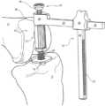
ここで図44Aを参照すると、組み立てられた発明の一実施形態が示される。この実施形態では、屈曲ボルト120は、ラチェットデバイス142で置き換えられる。ラチェットデバイス142は、一般に、ハンドル部分143と、付勢部分144と、ギアボックス145と、を含む。ラチェットデバイス142の付勢部分144は、ねじ山付き胴部115とブッシング125との間に介在している。次いで、ハンドル部分143を作動させて、付勢部分144に大腿骨11を脛骨12から離れるように持ち上げる。ギアボックス145は、ハンドル部分143の運動または作動を変換して、付勢部分144の位置を変え、膝関節を分離する。Now referring to FIG. 44A, one embodiment of the invention is shown assembled. In this embodiment, the
ハンドル部分143は、医師がハンドル部分143を操作して、デバイス142の付勢部分144を作動させることができる任意の構成を含んでもよい。例えば、一実施形態では、ハンドル部分143は、各々が遠位端にグリップ148を有し、かつ近位端にギアボックス145内に延在する、一対の対向するレバー146および147を含む。デバイス142の付勢部分144は、一対の対向するレバー146および147が近位位置に来るように、ハンドル部分143を把持して圧迫することによって作動させられる。対向するレバー146および147の作動は、ギアボックス145を操作して、付勢部分144を近位位置から離れるように移動させる。さらに、一実施形態では、ギアボックス145は、付勢部分144を近位位置に戻すための解除部を含む。The
別の実施形態では、ハンドル部分143は、遠位端にハンドルを有し、かつ近位端にギアボックス145内に延在する、単一のシャフトを含む。この実施形態では、デバイス142の付勢部分144は、ハンドル部分143を時計回りまたは反時計回りの方向に回転させることによって作動させられる。ハンドル部分143の回転動作は、ギアボックス145を操作して、付勢部分144を近位位置から離れるように、または近位位置に向かうように移動させる。一実施形態では、ギアボックス145は、使用中に付勢部分144の付勢位置を維持するための爪または他のデバイスをさらに含む。したがって、医師は、デバイス142を作動させて、膝を所望の位置または引張位に分離し、次いでその張力をハンズフリーに維持してもよい。In another embodiment, the
付勢部分143は、ねじ山付き胴部115およびブッシング125内に装着することができる任意の構成を含んでもよい。例えば、一実施形態では、付勢部分143は、ねじ山付き胴部115およびブッシング125と係合するための第1の端部を有し、ギアボックス145内に延在する第2の端部を有する、一対のジョー148を含む。別の実施形態では、第1の端部は、ねじ山付き胴部115およびブッシング125と係合するための接合コネクタ149をさらに含む。接合コネクタ149は、一対のジョー148が膝関節を分離することを許容するが、依然として引張プロセス全体を通して患者の膝の自然な生理機能に適応するように膝関節の制限された移動を提供する。The biasing
ギアボックス145は、膝関節の制御された分離を達成するために、ハンドル部分143および付勢部分144と適合可能なギアの任意の構成を含んでもよい。ギアボックス145はまた、膝関節に配置される張力を制限または測定するための任意の手段も含んでもよい。例えば、一実施形態では、ギアボックス145は張力計151をさらに含み、それによってラチェットデバイス142によって膝関節に配置される張力が表示される。別の実施形態では、ギアボックス145は、調整ねじ152をさらに含み、それによってラチェットデバイス142の最大許容張力が設定される。この実施形態では、医師は、調節ねじ152を所望の張力に調整する。一旦設定されると、医師は、ラチェットデバイス142を作動させて膝関節を分離する。所望の張力が達成されると、ラチェットデバイス142の作動によるさらなる引張が妨げられ、したがって膝の所望の張力が維持される。図44Aに示される装置は任意の好適な機能を果たすことができるが、いくつかの実施形態では、図44Aは、ラチェットデバイス142(および/または任意の他の好適なデバイス)が、2つの骨が互いに引張されているとき(例えば、膝関節が屈曲位および/または伸長位にあるとき)に、脛骨12と大腿骨11との間の内反-外反角形成の変化が生じることを可能にすることを示す。The
ここで図45を参照すると、切除ブロック180は、切除ブロックガイド165に取り付けられ、かつ大腿骨11の前方表面に対して適所に摺動される。切除ブロック180は、ガイド165の切り欠き166に対して止めねじ183を締め付けることによって、切除ブロックガイド165に固定される。切除ブロック180は次いで、複数のねじ181を介して大腿骨11に固定される。切除ブロック180が適所に固定されると、屈曲ボルト120を外科用工具組立体から取り外し、切除ブロック180の切断ガイド182を使用して、外側顆および内側顆の露出した遠位面を切除する。45, the
ここで図46~図48を参照すると、本発明の実装形態が膝伸長時の手術のために提供されている。図46を参照すると、伸長ボルト130が、大腿骨マウント150と脛骨引張アダプタ160との間に挿入される前に示される。伸長ボルト130は、一般に、ねじ山付きシャフト131と、円形フランジ132と、中央に配置されたボール134と、を含む。ねじ山付きシャフト131は、大腿骨マウント150のねじ切りされた開口部129内に適合的にねじ込まれるように構成されている。円形フランジ132は、ねじ山付きシャフト131に垂直に取り付けられ、ねじ山付きシャフト131と中央に配置されたボール134との間に介在する。フランジ132は、フランジ132の周縁部の周りに均等に間隔を空けて配置された複数の装着穴133を有する円板形状である。装着穴133は、伸長ボルト130を回すためのトルクレンチ140または他のデバイスを適合的に受容するようなサイズおよび構成にされる。46-48, an implementation of the present invention is provided for a knee extension procedure. Referring to FIG. 46, an
中央に配置されたボール134は、脛骨引張アダプタ160の開口部162内に部分的に挿入するようにサイズ設定および構成された半球形状の表面を含む。したがって、中央に配置されたボール134は、開口部162と部分的に係合するが、依然として大腿骨11と脛骨12との間に軸方向の回転を提供するのに十分自由なままである。中央に配置されたボール134と開口部162との間の界面はさらに、大腿骨マウント150と脛骨引張アダプタ160との正確な位置合わせを確実にする。先で考察されたように、かつ図47に示されるように、円形フランジ132とスペーサ163との間の界面158に起因して、大腿骨11および脛骨12に半径方向の回転がさらに提供される。したがって、伸長ボルト130は、引張および切除処置の間、大腿骨11および脛骨12に対する位置合わせおよび制限された自由な調節の両方を提供する。The centrally located
一実施形態では、図46に示されるように、膝が屈曲位にあるときに、ねじ山付きシャフト131を大腿骨マウント150のねじ山付き開口部129にねじ込むことによって、まず伸長ボルト130を大腿骨マウント150に連結する。伸長ボルト130は、大腿骨11と脛骨12との間の距離を最小化するために、ねじ山付き開口部129内に最大限に挿入される。次いで、図47に示されるように、膝は伸長位置まで来て、中央に配置されたボール134を開口部162に挿入される。次に、トルクレンチ140を利用して、伸長ボルト130を回転させて膝に張力を加える。トルクレンチ140は、円形フランジ132の穴133に挿入され、ねじ切り開口部129から伸長ボルト130を徐々に取り外すように回される。一実施形態では、医師は、伸長ボルト130の回転中に、脛骨12の回転を防ぐために切除ブロックガイド165を固定する。医師は、所望の張力が膝の靭帯に配置されるまで、伸長ボルト130を回し続ける。あるいは、ラチェットデバイス(図44Aを参照)を、膝が伸長位にある状態で使用して、膝の靭帯に所望の張力を配置してもよい。一実施形態では、伸長位の最終張力は屈曲位の最終張力に等しい。別の実施形態では、伸長位の最終張力は屈曲位の最終張力とは異なる。In one embodiment, the
図46および図47に示されるように、記載されたシステムのいくつかの実施形態は、膝関節が引張状態にあるときに、膝関節の内反-外反角形成を変化させるために、膝関節の大腿骨11および脛骨12が互いに対して回転することを可能にするように構成される。したがって、いくつかの実施形態では、記載されたシステムは、完全または部分的な膝関節置換術の間に適切な張力、間隙の平衡、および内反-外反角形成を比較的容易かつ迅速に達成することを可能にする。As shown in Figures 46 and 47, some embodiments of the described system are configured to allow the
ここで図48を参照すると、切除ブロック180は、切除ブロックガイド165に取り付けられ、かつ図45に関連して上で考察されたように、大腿骨11の前方表面に対して適所に摺動される。一旦位置決めされると、切除ブロック180は、ねじ181で大腿骨11に固定され、外側および内側顆の前方表面が切除される。Referring now to FIG. 48, the
別の実施形態では、ガイド組立体は骨にしっかりと固定され、膝関節準備の本質的なステップの間に適所に残されるので、コンピュータ支援ガイドはガイド組立体器具に取り付けられ、それによりコンピュータ支援膝関節全置換術を容易にする。本発明の他の実施形態では、ガイド組立体器具は、部分または膝関節片側置換術処置で使用するために変更される。In another embodiment, a computer-assisted guide is attached to the guide assembly instrument as the guide assembly is fixedly secured to the bone and left in place during the essential steps of knee preparation, thereby facilitating computer-assisted total knee arthroplasty. In other embodiments of the invention, the guide assembly instrument is modified for use in partial or unilateral knee arthroplasty procedures.
いくつかの実施形態では、ガイド組立体器具は、髄外膝関節準備のためのIMロッドの代わりに短いIMロッドまたは脛骨プラットフォームと共に使用するために変更され得る。In some embodiments, the guide assembly instrument can be modified for use with a short IM rod or tibial platform in place of an IM rod for extramedullary knee preparation.
いくつかの実施形態では、ガイド組立体は患者の脚を適所に保持する。これにより、医療助手が患者の脚を握る必要性が少なくなる。In some embodiments, the guide assembly holds the patient's leg in place, reducing the need for the medical assistant to grasp the patient's leg.
患者の膝関節の完全な切除に続いて、大腿骨11および脛骨12の切除された部分は、図49および図50に示されるように、膝プロテーゼまたはインプラント200によって置き換えられる。膝インプラント200は、一般に、大腿骨コンポーネント202と、脛骨コンポーネント204と、を含む。本発明の器具は、任意のタイプの膝プロテーゼ200と共に使用され得るが、これらの器具は、ライトメディカルテクノロジー社のADVANCE(登録商標)Medial Pivot膝インプラントなど、一次屈曲範囲全体にわたって等半径を用いる膝プロテーゼを受容するために、膝を正確に切除する際に使用するのに特に適している。等半径膝プロテーゼの特徴および特性は、当業者にはよく知られているが、これまで膝引張切除器具と共に使用されたことはなかった。以下に記載されるように、従来技術の等半径膝関節インプラントと組み合わせて引張器具を使用することによって、相乗的でかつこれまでに認められていなかった効果が得られる。この相乗的な組み合わせの最終的な結果は、等半径膝関節インプラントの移植における全体的な精度がより高くなり、結果として臨床転帰が改善されることが予想される。Following complete resection of the patient's knee, the resected portions of the
適切に設計されて移植された等半径膝プロテーゼの利点のうちの1つは、それが主要な屈曲範囲全体にわたって一定の靭帯張力を患者に提供することである。本明細書で考察されたように、最適な張力下にある間に膝を切除するための本発明の器具の使用は、膝インプラントコンポーネントの正確な配置を保証するのを助ける。引張器具と等半径膝インプラントの併用は、主要な屈曲範囲全体にわたって一定の靭帯張力を達成する可能性を改善する。等半径を組み込んでいる膝インプラントの様々な実施形態は、参照により本明細書に組み込まれている、以下の先行技術文献において考察されている。米国特許第7,261,740号、米国特許第6,013,103号、米国特許第6,013,103号、米国特許第5,824,100号、米国特許第5,330,533号、米国特許第5,326,361号、米国特許第5,314,482号、米国特許第5,219,362号、米国特許第5,133,758号、米国特許第4,085,466号、ドイツ特許出願第3314038(A1)号。One of the advantages of a properly designed and implanted isoradius knee prosthesis is that it provides the patient with constant ligament tension throughout the primary range of flexion. As discussed herein, the use of the inventive instrument to resect the knee while under optimal tension helps ensure accurate placement of the knee implant components. The use of a tensioning instrument in conjunction with an isoradius knee implant improves the likelihood of achieving constant ligament tension throughout the primary range of flexion. Various embodiments of knee implants incorporating isoradii are discussed in the following prior art documents, which are incorporated herein by reference: U.S. Patent No. 7,261,740, U.S. Patent No. 6,013,103, U.S. Patent No. 6,013,103, U.S. Patent No. 5,824,100, U.S. Patent No. 5,330,533, U.S. Patent No. 5,326,361, U.S. Patent No. 5,314,482, U.S. Patent No. 5,219,362, U.S. Patent No. 5,133,758, U.S. Patent No. 4,085,466, German Patent Application No. 3314038 (A1).
先行技術のADVANCE(登録商標)Medial Pivot膝インプラントでは、大腿骨コンポーネント202は、内側側部に球状顆206を有する。図51に示されるように、矢状平面またはA-P平面において、内側大腿骨顆206は、少なくとも一次屈曲範囲にわたって等半径226を有し、これは、患者に応じて約0度の伸長位から約90度の屈曲位まで延在する。外側大腿骨顆222はまた、一次屈曲範囲全体にわたってA-P等半径226を有する。ADVANCE(登録商標)Medial Pivot膝関節の脛骨ベース204の内側側部は、浅い球形の凹状の支承面232を有し、これは、ボール-ソケット様態で内側大腿骨顆206を密接に受容するようなサイズにされている。脛骨ベース204の外側側部は、一般に、細長い弓形の谷230の形態である。これらの特徴部は、内側大腿骨顆206が屈曲中に内側脛骨軸受232内で枢動することを可能にする一方で、同時に、外側大腿骨顆222が外側脛骨軸受218内で後方に並進することを可能にする。この動作は、運動中に内側大腿顆が外側顆よりも少ないロールバックを示す、自然な膝の機能を模倣するように設計されている。ADVANCE(登録商標)Medial Pivot膝の特徴および特性は、参照により本明細書に組み込まれる、米国特許第5,964,808号および同第6,013,103号にさらに詳細に考察されている。ADVANCE(登録商標)Medial Pivot膝インプラントは、本発明の引張器具の使用を最適化および補完するための例示的なインプラント設計であるが、同様または同等の効果に対して他の等半径の膝インプラント設計が使用され得る。In the prior art ADVANCE® Medial Pivot knee implant, the
従来技術の膝用器具の欠点のうちの1つは、関節の過剰充填または過少充填が時々起こり、その結果、靭帯にそれぞれ締め付けまたは弛緩が生じることである。上で考察されたように、屈曲位にある以前に位置決めされた膝に対して行われた引張切除と比較すると、伸長位置で引張された膝を切除するための引張器具の使用により、ユーザが平衡化された伸長の間隙を切除することが可能になる。切除切断は単一の基準点から作られ、単一の基準点は所望の量の張力である。同等の屈曲間隙および伸長の間隙の使用により、その間のすべての点で自動的に中屈曲間隙が平衡化される。次いで、等半径の膝インプラントを切除された膝の上に移植することによって、外科医は、引張器具によって得られた最適な張力を等半径の膝インプラントに効果的に伝達し、少なくとも一次屈曲範囲にわたって安定して滑らかに機能する膝をもたらす。機械的には、引張技術は、軸受に予圧をかけ、軸受は、等半径の膝インプラントである。One of the shortcomings of prior art knee instruments is that overfilling or underfilling of the joint sometimes occurs, resulting in tightness or looseness of the ligaments, respectively. As discussed above, in comparison to tension resections performed on previously positioned knees in flexion, the use of tensioning instruments to resect a tensioned knee in extension allows the user to resect a balanced extension gap. The resection cuts are made from a single reference point, which is the desired amount of tension. The use of equal flexion and extension gaps automatically balances the mid-flexion gap at all points in between. By then implanting an equal-radius knee implant over the resected knee, the surgeon effectively transfers the optimal tension achieved by the tensioning instruments to the equal-radius knee implant, resulting in a knee that functions stably and smoothly through at least the primary range of flexion. Mechanically, the tensioning technique preloads a bearing, which is an equal-radius knee implant.
対照的に、等半径インプラントではなく、従来のJ形曲線または可変半径膝関節インプラントが引張技術と共に使用される場合、同等の屈曲間隙および伸長間隙を使用する代わりに切断部を変えることが必要になる。したがって、様々な半径の膝インプラントの使用は必然的にプロセスおよび器具の使用を複雑にする。In contrast, when traditional J-curve or variable radius knee implants are used with tension techniques, rather than equal radius implants, varying cuts are required instead of using equal flexion and extension gaps. Thus, the use of knee implants of varying radii necessarily complicates the process and instrumentation.
記載されたシステムおよび方法の前述のコンポーネントおよび特徴部に加えて、いくつかの実施形態では、記載されたシステムおよび方法は、1つ以上のロボット、ロボットアーム、腹腔鏡デバイス、および/または他の自動化デバイスと共に使用されるように構成される。実際、いくつかの実施形態によれば、記載されたシステムおよび方法は、膝関節および自動化デバイス(例えば、米国ミシガン州カラマズーのStrykerによって製造されたMAKO(商標)ロボットアームおよび/もしくは任意の他の好適なロボット、ならびに/または自動化組立体)に所望の張力を提供するために使用され、次いで、膝関節内の骨のうちの1つ以上の部分を切除するために使用される。そのような実施形態では、自動化デバイスは、任意の好適な様態で切断を行うことができる。実際、いくつかの実施形態では、自動化デバイスは、1つ以上の切断ガイド54、大腿骨切断ガイド部分90、屈曲膝切断ガイド組立体52、および/または切断工具を方向付けるように構成されている任意の他の好適なコンポーネントを使用する。しかしながら、いくつかの他の実施形態では、自動化デバイスは、記載された切断ガイドまたはガイド/切除ブロックを使用せずに、膝関節に所望の切断を行うように構成されている。In addition to the aforementioned components and features of the described systems and methods, in some embodiments, the described systems and methods are configured to be used with one or more robots, robotic arms, laparoscopic devices, and/or other automated devices. Indeed, according to some embodiments, the described systems and methods are used to provide a desired tension to a knee joint and an automated device (e.g., a MAKO™ robotic arm manufactured by Stryker, Kalamazoo, Michigan, USA, and/or any other suitable robot and/or automated assembly) that is then used to resect one or more portions of the bone in the knee joint. In such embodiments, the automated device can perform the cut in any suitable manner. Indeed, in some embodiments, the automated device uses one or more cutting guides 54, femoral cutting guide portion 90, flexed knee cutting guide assembly 52, and/or any other suitable components configured to direct the cutting tool. However, in some other embodiments, the automated device is configured to perform the desired cut in the knee joint without the use of the described cutting guides or guide/resection blocks.
好適な変更の別の例として、記載された装置およびシステムのいくつかの実施形態は、関節の運動範囲全体にわたって膝関節の1つ以上の靭帯の張力を維持するように構成される。これに関して、いくつかの実施形態では、記載されたシステムおよび方法の1つ以上のコンポーネントは、屈曲位(例えば、図7~図15、図33~図37、および図43~図45に示されるように)、および伸長位(例えば、図9~図19、図38~図40、および図46~図48に示されるように)にある膝関節の張力の調整の間で切り替えられる。As another example of a suitable modification, some embodiments of the described devices and systems are configured to maintain tension in one or more ligaments of a knee joint throughout the joint's range of motion. In this regard, in some embodiments, one or more components of the described systems and methods are switched between adjusting tension in a knee joint in flexion (e.g., as shown in Figures 7-15, 33-37, and 43-45) and extension (e.g., as shown in Figures 9-19, 38-40, and 46-48).
しかしながら、いくつかの他の実施形態では、記載されたシステムおよび方法は、大腿骨コンポーネント(例えば、大腿骨IMロッド13、大腿骨マウント15、二次大腿骨マウント100、大腿骨マウントの開口部129、および/または任意の他の好適な大腿骨コンポーネント)、脛骨コンポーネント(例えば、脛骨IMロッド14、脛骨マウント23、プラトーフランジ28、脛骨引張アダプタ160、引張アダプタの穴162、および/または任意の他の好適な脛骨コンポーネント)、引張組立体(例えば、屈曲ボルト30、伸長ボルト96、ゲージブロック76、ブッシング33、外反アダプタ部材110、屈曲ボルト120、ねじ山付き胴部115、ブッシング125、ラチェットデバイス142、伸長ボルト130、および/または膝関節内の張力を増加および/または減少するために使用される任意の他の好適なコンポーネント)、および/または記載されたシステムおよび方法の任意の他の好適なコンポーネント)のうちの一部を含み、かつ/またはそれらの間に延在する1つ以上の関節式コネクタを含む。However, in some other embodiments, the described systems and methods include one or more articulating connectors that include and/or extend between the femoral component (e.g.,
非限定的な例示として、図52Aは、いくつかの実施形態において、大腿骨IMロッド13は、大腿骨マウント15が、そのようなロッドを含む膝関節が異なるコンポーネントを伸長位および屈曲位において使用する必要なく、一定の運動範囲にわたって移動することができるように枢動することを可能にする、関節156を含むように構成されていることを示す。別の非限定的な例示では、図52Bは、いくつかの実施形態では、ガイドブロック76は、そのようなブロックと大腿骨マウント15とを含む膝関節(例えば、図1に示されるように)が、異なるコンポーネントを伸長位および屈曲位において使用する必要なく、一定の運動範囲にわたって移動することができるように枢動することを可能にする、関節156を含むことを示す。さらに別の非限定的な例示では、図52Cは、伸長ボルト130が、そのようなボルトと、脛骨引張アダプタ160と、を含む膝関節が、ボルトが異なるコンポーネント(例えば、伸長ボルトと屈曲ボルト)を伸長位および屈曲位において使用する必要なく、一定の運動範囲にわたって移動することができるように枢動することを可能にする関節156を含む一実施形態を示す。52A shows that in some embodiments, the
記載されたシステムおよび方法が1つ以上の関節式コネクタを含む場合、コネクタは、任意の好適なコンポーネントまたは特性を有し得る。例として、関節式コネクタは、非限定的に、1つ以上のピボット継手、ボール継手、ヒンジ継手、ユニバーサル継手、プリズム継手、ロトイド継手、および/またはそのようなコネクタが関節内に配設され、記載された装置およびシステムの1つ以上のコンポーネントに連結されるときに、膝関節が一定の運動範囲にわたって移動することを可能にする他の好適な継手を含む任意の好適なタイプの継手を含むことができる。別の例として、関節式コネクタのいくつかの実施形態は、大腿骨および/または脛骨の外側に十分な量のコネクタを保持して、各コネクタの一部分(したがって、コネクタを含む膝関節)が別の物体(例えば、骨、大腿骨コンポーネント、脛骨コンポーネントなど)に望ましくない影響を与えることなく、一定の運動範囲にわたって移動すること可能にするように構成されている1つ以上の止め具(例えば、隆起部、リング、突起、および/または他の止め部159)を含む。さらに別の例では、関節式コネクタのいくつかの実施形態は、1つ以上の戻り止め、係止部、係止機構、制限部、クランプ機構、および/またはコネクタが所望の位置から選択的に移動し、かつ/または所望の位置に保持されることを可能にする他の位置保持機構を含む。Where the described systems and methods include one or more articulating connectors, the connectors may have any suitable components or characteristics. By way of example, the articulating connectors may include any suitable type of joint, including, without limitation, one or more pivot joints, ball joints, hinge joints, universal joints, prism joints, rotoid joints, and/or other suitable joints that allow the knee joint to move through a range of motion when such connectors are disposed within the joint and coupled to one or more components of the described devices and systems. As another example, some embodiments of the articulating connectors include one or more stops (e.g., ridges, rings, protrusions, and/or other stops 159) that are configured to hold a sufficient amount of the connector on the outside of the femur and/or tibia to allow a portion of each connector (and thus the knee joint including the connectors) to move through a range of motion without undesirably affecting another object (e.g., bone, femoral component, tibial component, etc.). In yet another example, some embodiments of the articulating connector include one or more detents, locking portions, locking mechanisms, limiting portions, clamping mechanisms, and/or other position retention mechanisms that allow the connector to be selectively moved from and/or retained in a desired position.
骨切削
ここで記載された骨切削技術を参照すると、本発明のいくつかの実施形態は、切除のための膝の準備を誘導するための、および関節形成術中にインプラントを設置するための膝の準備を誘導するための、器具の使用に関する。特に、いくつかの実施形態は、所望の深さの孔を提供するために、特定の軸に沿って切削工具を誘導するためのシステムに関する。Bone Cutting With reference to the bone cutting techniques described herein, some embodiments of the invention relate to the use of instruments to guide the preparation of the knee for resection and for the placement of an implant during arthroplasty. In particular, some embodiments relate to a system for guiding a cutting tool along a particular axis to provide a hole of a desired depth.
ここで図53を参照すると、本発明の一実装形態の斜視図が、仮想線で示される、膝312内に屈曲位で位置決めされて示される。骨切削デバイス310は、切削ビット320と、ガイドロッド340と、を含む。骨切削デバイス310は、一般に、外科用鋼、チタン、アルミニウム、およびそれらの合金などの外科用用途に適合する外科用金属材料を含む。しかしながら、当業者であれば、テフロン(登録商標)およびナイロンなどの他の非金属材料を本開示の範囲内で本発明に組み込むことができることを理解するであろう。例えば、一実施形態では、摩擦を低減するためにテフロン(登録商標)コーティングが、骨切削デバイス310の対向する表面にコーティングされる。53, a perspective view of one implementation of the present invention is shown positioned in a flexed position within a knee 312, shown in phantom. The bone cutting device 310 includes a cutting
ここで図53~図55を参照すると、切削ビット320は、切断ヘッド部分322と、シャフト部分324と、を含む。切断ヘッド部分322は、より広いベース326と、シャフト部分324を接合するより狭い先細の頂部328と、を有する概ねベル形状である。本発明のいくつかの実装態様では、図55に示されるように、棚部または段差表面330が、深さゲージ360を支持するために、切断ヘッド部分322とシャフト部分324との間に挿入される。シャフト部分324は、切削ビット320をドリルまたはビット320を回転させるための他のデバイスに連結するためのシャンク366をさらに含む。Now referring to Figures 53-55, the cutting
切断ヘッド部分322は、取り外し可能な切刃332をさらに含む。取り外し可能な切刃332は、一般に、切断縁部334と、窓336と、を有する円板形状である。切断縁部334は、骨を通して切断して、孔350を形成するために提供される一方で、窓336は、切断された骨片を孔350から除去するために提供される。この様態で、孔350は、切削ビット320によって切断され、清掃される。切断ヘッド部分322は、取り外し可能な切刃332の窓336と位置合わせする窓338をさらに含む。したがって、骨片は切削ビット320の切断ヘッド部分322から完全に除去され、切削ビット320が孔350を形成する能力を妨げることはない。The cutting
切削ビット320は、シャフト部分324の中心コアおよび切断ヘッド部分322を通って延在するキャビティ352をさらに含む。キャビティ352は、一端が閉口されており、ビット320の切断ヘッド部分322に開口部354を含む。キャビティ352は、ガイドロッド340の一部分を回転可能に受容するように適合されている直径を含む。キャビティ352とガイドロッド340との間の公差は、ビット320がガイドロッド340の周りを自由に回転することを可能にしながら、ガイドロッド340の軸に対するビット320の移動を制御および制限する。したがって、キャビティ352とガイドロッド340との間の相互作用は、孔350の角度がガイドロッド340の角度と平行であることを確実にする。The cutting
ガイドロッド340は、孔350を受容することになる骨314の一部分内に挿入または固定される。典型的には、骨314は、骨の骨髄内(IM)管348内への接近または開口部346を提供するために予備穿孔される。予備穿孔処置は整形外科医学の分野に共通している。この処置に続いて、ガイドロッド340の第1の端部344は、開口部346内に挿入され、ガイドロッド340の第2の端部342の一部分が開口部346から外方に延在するように、IM管348内に位置決めされる。The
一実施形態では、ガイドロッド340の第1および第2の端部344および342は、ガイドロッド340を形成するようにねじ込み式で連結される。したがって、ガイドロッド340の第1の端部344は、複数の適合する外科用デバイスをねじ込み式に受容してもよい。例えば、一実施形態では、ガイドロッド340の第2の端部342は、孔350の形成に続いて除去され、関節形成術を完了するのに必要な別の外科用器具と交換される。In one embodiment, the first and second ends 344 and 342 of the
ガイドロッド340の第2の半分342は、支柱部分356と、ベース358と、を含む。ベース358は、第1の端部344にねじ込み式で連結され、一般に、第1の端部344と同じ直径を含む。支柱部分356は、ベース358から外方に延在し、実質的にIM管348の外側に位置決めされる。先で考察されたように、支柱部分356の直径は、切削ビット320のキャビティ352内に回転可能に挿入されるように選択および適合される。一実施形態では、ベース358の直径は、IM管と接触しているガイドロッド340の表面積を増大させるように、支柱部分356の直径よりも大きく作られているが、依然として支柱部分356にキャビティ352と適合する直径を提供する。別の実施形態では、ベース358および第1の端部344は、IM管348との接触を強化するための溝付き外面をさらに含み、IM管348内でのガイドロッド340の回転を妨げる。The second half 342 of the
IM管内のガイドロッド340の深さおよび位置決めは、切削ビット320が孔350を所望の深さまで正確に切断することを可能にするように選択される。孔350の深さの精度は、あらゆる関節形成術処置の重要な要素である。したがって、切削デバイス310は、孔350の深さを正確に決定するための手段をさらに含む。例えば、一実施形態では、シャフト部分324の外面は、複数の環状基準マーク368を含む。基準マーク368は、切断されている骨上の様々な生理学的基準に対する取り外し可能な切刃332の深さの視覚的指標を提供する。孔350が脛骨314に切断されている一実施形態では、孔350の必要な深さは、骨の通常の高さ370より2mm下、脛骨棘372より13mm下、または外側側部374の10mm下のいずれかである。したがって、基準マーク368は、孔350の深さを決定するために、生理学的基準370、372、および374に対して観察される。大腿骨316などの別の骨に孔が切断される場合、当技術分野で知られているように、他の骨基準が使用される。The depth and positioning of the
別の実施形態では、深さゲージ360は、ビット320のシャフト部分324の上に配置され、段差表面330によって支持される。深さゲージ360は、ベース362と、アーム364と、ピン366と、を含む。ベース362は、ビット320のシャフト部分324を回転可能に受容するための直径を有する孔をさらに含む。アーム364は、ピン366を孔350を越えて位置決めするように、ベース362から外方に延在する。一実施形態では、アーム364は、アーム364の長さを調節するための関節をさらに含む。別の実施形態では、アーム364は、ピン366をアーム364に対して所望の位置に調節および係止するための止めねじをさらに含む。さらに別の実施形態では、切断されている骨に関する様々な生理学的基準を収容するために複数の深さゲージ360が提供される。In another embodiment, the depth gauge 360 is disposed on the
深さゲージ360は、先で考察されたように、様々な生理学的基準に対する取り外し可能な切刃332の深さの物理的な指標を提供する。一実施形態では、深さゲージ360は、段差表面330に着座し、アーム364およびピン366は、所望の生理学的基準374と位置合わせするように調節される。さらに、ピン366の高さは、生理学的基準に対して設定されて、所望の深さの孔350を形成する。その後、深さゲージ360は、適所に保持され、ビット320が回転して孔350を形成している間、回転が妨げられる。ピン366が生理学的基準374に接触すると、ビット320は、孔350から除去され、所望の深さを達成する。The depth gauge 360 provides a physical indication of the depth of the
ここで図56を参照すると、孔350を所望の深さまで正確に切断するための別の方法が示されている。この方法では、切断ビット320がガイドロッド340のベース358に接触するまで骨314内に切断することによって、所望の孔350の深さが達成される。この方法では、ガイドロッド340のベース358が、切刃332の切断縁部334に対して、IM管348内に正確に位置決めされることが必要である。したがって、切断ヘッド322がベース358に接触する点まで、切刃332は、ガイドロッド340に沿って骨314内に切断されて下降する。切断ヘッド322とベース358との間の接触が生じると、切削ビット320は、孔350から除去される。一実施形態では、切削ビットの切断ヘッド部分322は、支柱部分356のベース358を適合的かつ回転可能に受容するように適合された直径を有する凹状区画380を含む。したがって、この実施形態では、ベース358の深さは、ベース358が凹状区画380と完全に係合するときに、切刃332の切断縁部334が孔350の所望の深さに正確に位置決めされるように、IM管348内に設定される。いくつかの異なる方法が考察されてきたが、当業者であれば、他の様々な方法および装置が、切削デバイス310とうまく組み合わされて所望の結果を達成することができることを理解するであろう。56, another method for precisely cutting a hole 350 to a desired depth is shown. In this method, the desired hole 350 depth is achieved by cutting into the
ここで図57を参照すると、孔350の形成後および切除前の脛骨314が示される。一旦孔350が提供されると、ガイドロッド340をさらに利用して、関節形成術処置を完了するのを助けてもよい。例えば、一実施形態では、切除ブロック390は、チャネル402を介してガイドロッド340の上に位置決めされ、孔350内に着座する。切除ブロック390は、ベース392と、アーム394と、切断ガイドブロック396と、を含む。ベースは、孔350の直径に等しい直径を有するフランジ部分400をさらに含む。さらに、ベース392は、ガイドロッド340の支柱部分356およびベース358と適合的に係合するように適合された外形および寸法を有するチャネル402を含む。したがって、切除ブロック390は、孔350内に正確に着座し、ガイドロッド340の介在的および補完的表面によって安定している。57, the
切除ブロック390のアーム394は、骨314の外側側部374に等しい高さでベース392に取り付けられる。したがって、アーム394は、骨314の表面を清掃し、孔350を越えてベース392から外側に延在する。一実施形態では、切除ブロック490は、図57Aに示されるように、関節形成術を受けている骨314の個々の生理学的特徴によって必要とされる場合、孔350の深さおよび位置に対してアーム394を位置決めするための複数の調節部408をさらに含む。したがって、1つの切除ブロック390は、無限に調節され、必要とされる場合、任意の処置と共に使用するために適合されてもよい。The arms 394 of the resection block 390 are attached to the base 392 at a height equal to the
切断ガイドブロック396は、ベース392とは反対側にあるアーム394の端部に取り付けらる。切断ガイドブロック396は、鋸刃(図示せず)がスロット404を通って挿入されて、骨314を孔350の深さまで切除し得るように位置決めされる。一実施形態では、切除ブロック390は、図57Aに示されるように、切除を受けている間に、骨部分370、372、および374の個々の生理学的特徴部によって必要とされる場合、孔350の深さおよび位置に対して切断ブロックガイド396を位置決めするための複数の調節部412をさらに含む。本発明のいくつかの実装形態では、切断ブロックガイド396は、締結具を介して切断ブロックガイド396を骨314に取り付けるための複数の孔をさらに含む。他の実装形態では、複数の調節部は、切断ブロックガイド396をアーム394から取り外すことを許容する。したがって、一実施形態では、切断ブロックガイド396は、正確な位置決めを確実にするために、最初に締結具で骨314上に位置決めされ、かつ骨314に取り付けられる。取り付けに続いて、切断ブロックガイド396を切除ブロック390の残りの部分から取り外し、切除を行う。したがって、最小限の部品で正確かつ効率的に切除が行われる。A cutting guide block 396 is attached to the end of the arm 394 opposite the base 392. The cutting guide block 396 is positioned so that a saw blade (not shown) can be inserted through the slot 404 to resect the
別の実施形態では、大腿骨切断を実施するための器具が、孔350の最終深さに挿入され、かつ/またはそこから参照される。孔350の深さは、脛骨切断部の最終レベルであるので、すべての大腿骨切断部は、孔350の深さから正確に参照され得る。したがって、孔350は、脛骨314に対して十分かつ比較的非侵襲的な基準点を提供する。大腿骨切断が行われると、脛骨314の残りの切断されていない部分が露出され、切除のために容易に接近可能になる。別の実施形態では、切除処置の一部として、膝312に張力をかけるために、引張デバイスが、ガイドロッド340、切除ブロック390、および孔340と組み合わさる。2006年2月8日に出願され、「GUIDE ASSEMBLY FOR GUIDING CUTS TO A FEMUR AND TIBIA DURING A KNEE ARTHROPLASTY」と題する米国特許出願公開第11/349,772号(現在は米国特許第7,927,336号)、および2008年8月13日に出願され、「SYSTEMS AND METHODS FOR GUIDING CUTS TO A FEMUR AND TIBIA DURING A KNEE ARTHROPLASTY」と題する米国特許出願第12/191,245号(現在の米国特許第8,303,597号)に教示されているような引張デバイスおよび処置は、本デバイス310と容易に組み合わせられてもよく、それらの全体が参照により本明細書に組み込まれる。器具および骨314に対する変更は、以下の図57Bに関連して考察される。In another embodiment, the instruments for performing the femoral cuts are inserted and/or referenced from the final depth of the hole 350. Because the depth of the hole 350 is the final level of the tibial cuts, all femoral cuts can be precisely referenced from the depth of the hole 350. Thus, the hole 350 provides a sufficient and relatively non-invasive reference point for the
ここで図57Bを参照すると、切除ブロックの実装形態が、ガイドロッド340の第1の端部344と組み合わされたものとして示される。この実施形態では、ガイドロッド340の支柱部分または第2の端部342は、第1の端部344から除去され、切除ブロックシステム440と交換される。切除ブロックシステム440は、一体型のベース442およびアーム444、ならびにそり式の切断ガイドブロック450を含む。ベース442は、孔350の直径よりもわずかに小さい直径を有する円板形状である。アーム444は、ベース442と同じ平面内でベース442から外側外方に延在する。したがって、骨314の一部分460は、アーム444のための経路を提供するために除去されなければならない。一実施形態では、骨部分460を除去して経路を形成するために、骨鉗子または他の外科用デバイスが使用される。骨部分460が除去されると、ガイドロッド340の第1の端部344は、取り付けられたシステム440と共に、IM管348内に再位置決めされる。次に、切断ガイドブロック450は、アーム444の遠位端446の上で摺動し、骨314に対して位置決めされる。この時点で、切断ガイドブロック450は、締結具を介して骨に固定的に取り付けられ、必要な切除は、スロット404を介して行われる。一実施形態では、切断ガイドブロック450は、ガイドブロック450が骨314に締結されている間に、アーム444からガイドブロック450を解除するための手段をさらに含む。例えば、ガイドブロック450の上部452は、取り外し可能であり、それによってブロック450の下部の締結された半分をシステム440の残りの部分から解除するように適合されてもよい。57B, an implementation of a resection block is shown combined with a
代替の実施形態では、切断ガイドブロック450は、ガイドブロック450のスロット404が脛骨314ではなく大腿骨316と位置合わせするように、最初にアーム444の遠位端446の上で摺動する。この構成において、ガイドブロック450は、大腿骨切断を行うために、孔350の深さに対して位置決めされる。したがって、脛骨314の孔350は、大腿骨切断を正確に行うための基準点として機能する。一旦大腿骨の切断が行われると、ガイドブロック450が除去され、先で考察されたように、脛骨の切断を行うために再位置決めされる。In an alternative embodiment, the cutting guide block 450 is initially slid over the distal end 446 of the arm 444 such that the slot 404 of the guide block 450 aligns with the
ここで図58および59を参照すると、切削ビット320の実装形態の様々な斜視図が示される。特に注目すべきは、取り外し可能な切刃332の様々な構成である。取り外し可能な切刃332は、一組のねじ410を介して切断ヘッド部分322に取り付けられる。したがって、切刃332は、ビット320から容易に除去されて、切刃332の鋭利化および/または交換を可能にする。図58に示されるように、取り外し可能な切刃332のいくつかの実装形態は、単一の窓336と、単一の切刃334と、を含む。図559に示されるように、取り外し可能な切刃332のいくつかの実装形態は、複数の窓336と、複数の切刃334と、を含む。58 and 59, various perspective views of implementations of the cutting
ここで図60を参照すると、骨切削デバイス420の実装形態が示される。先で考察された骨切削デバイス310とは異なり、本デバイス420は、骨切削デバイス310のすべての要素を単一のユニット420に組み合わせる。骨切削デバイス420は、ガイドロッド422と、切断ヘッド部分424と、シャンク426と、を含む。ガイドロッド422は、骨316の開口部346内に回転可能に挿入されるようにサイズ決めされて適合されている。これによって、ガイドロッド422は、切断ヘッド部分424を骨346の開口部346内に位置合わせして方向付ける。シャンク426は、先で考察されたように、切削デバイス420をドリル(図示せず)または切削デバイス420を回転させるための他の手段に連結する。60, an implementation of a bone cutting device 420 is shown. Unlike the bone cutting device 310 discussed above, the present device 420 combines all of the elements of the bone cutting device 310 into a single unit 420. The bone cutting device 420 includes a guide rod 422, a cutting head portion 424, and a shank 426. The guide rod 422 is sized and adapted to be rotatably inserted into the opening 346 of the
切断ヘッド部分424は、環状に配置された複数の切断歯430を含む。以前の実施形態の切断縁部334とは異なり、切断歯430は、ガイドロッド422から半径方向外方に延在する鋭利な縁部の波形表面を提供する。したがって、切断歯430は、開口部346の隣接する表面に接触し、かつこれを研削して、骨316の表面のあらゆる不一致のある特徴部または隆起部を水平化するか、またはたたき落とす。したがって、切断歯430は、切断ヘッド部分424の直径に等しい直径を有する均一な表面を提供する。切削デバイス420は、開口部346に隣接して水平で安定した骨表面が必要とされる場合に有用である。切削デバイス420のいくつかの実装形態では、切断ヘッド部分424は、骨316に孔を形成するための複数の切断縁部および窓を含む。The cutting head portion 424 includes a plurality of cutting teeth 430 arranged in an annular configuration. Unlike the cutting
骨切削デバイス310を使用するための記載されたシステムおよび方法は、任意の好適な様態で変更され得るが、いくつかの実施形態では、骨切削デバイスは、1つ以上のロボット、ロボットアーム、腹腔鏡デバイス、および/または他の自動化デバイスによって操作される。そのような実施形態では、自動化デバイスは、ガイドロッド(例えば、ガイドロッド340、ガイドロッド422など)の使用の有無を問わず、脛骨および/または大腿骨に切断して切断を行うことができる。実際、いくつかの実施形態では、自動化デバイスは、切除中に骨切削デバイス内に延在するガイドロッドを使用することなく、膝を安定させ、脛骨および/または大腿骨の一部分を切断するために、骨切削デバイスを使用することができる。While the described systems and methods for using the bone cutting device 310 may be modified in any suitable manner, in some embodiments, the bone cutting device is operated by one or more robots, robotic arms, laparoscopic devices, and/or other automated devices. In such embodiments, the automated device can cut into the tibia and/or femur with or without the use of guide rods (e.g., guide
自動化デバイス(例えば、記載された骨切削デバイス310および/または任意の他の好適なデバイスを含むロボットアーム)を使用して、脛骨および/または大腿骨の一部分を切断する場合、自動化デバイスは、脛骨および/または大腿骨の任意の好適な一部分を切断することができる。実際、いくつかの実施形態では、自動化デバイス280は、孔350を脛骨に切断するように構成される(例えば、図61を参照)。When an automated device (e.g., a robotic arm including the bone cutting device 310 described and/or any other suitable device) is used to cut a portion of the tibia and/or femur, the automated device can cut any suitable portion of the tibia and/or femur. Indeed, in some embodiments, the automated device 280 is configured to cut a hole 350 into the tibia (see, e.g., FIG. 61).
いくつかのそのような実施形態では、孔が自動化デバイス280によって脛骨に切断された後、人は次に、切断デバイス(例えば、骨鋸)を使用して、脛骨の近位端の孔350の周囲の骨を孔の最終深さまで除去するが、いくつかの他の実施形態では、自動化デバイスは、切削工具310(および/または任意の他の好適な切断工具)を使用して、孔の周囲の骨を除去する。そのような実施形態では、自動化デバイスは、非限定的に、脛骨の近位端を横切って左右に切断すること(例えば、切削デバイスおよび/または任意の他の好適な切断工具を用いて)によるもの、切断部の間で切削工具(または他の切断デバイス)を持ち上げ、次にそれを孔の周りの(および/またはそれと重なる)骨の中へ遠位方向に孔の深さまで押し込むことによるもの、および/または脛骨プロテーゼの移植を可能にするために脛骨の近位端から骨を除去する任意の他の好適な様態を含む任意の好適な様態で末梢骨を除去することができる。In some such embodiments, after the hole is cut in the tibia by the automated device 280, a person then uses a cutting device (e.g., a bone saw) to remove bone around the hole 350 at the proximal end of the tibia to the final depth of the hole, while in some other embodiments, the automated device uses a cutting tool 310 (and/or any other suitable cutting tool) to remove bone around the hole. In such embodiments, the automated device can remove the peripheral bone in any suitable manner, including, but not limited to, by cutting side-to-side across the proximal end of the tibia (e.g., with a cutting device and/or any other suitable cutting tool), by lifting the cutting tool (or other cutting device) between cuts and then forcing it distally into the bone around (and/or overlapping) the hole to the depth of the hole, and/or any other suitable manner of removing bone from the proximal end of the tibia to allow for implantation of a tibial prosthesis.
いくつかの実施形態では、自動化デバイス280は、大腿骨の遠位端に1つ以上の切断を行う切削工具310(および/または任意の他の好適な切断デバイス)を使用するように、さらに構成される。いくつかのそのような実施形態では、切削工具の切断ヘッド部分322の直径は、それが切断に使用されるであろう各個々の顆の内側-外側幅と実質的に等しく、および/またはそれよりも大きくなるように構成される。したがって、いくつかの実施形態では、切削工具が大腿骨顆の一部分(例えば、中央および/または他の部分)と接触するように配置されて回ると、切削工具は、平坦な表面を大腿骨顆に切断するであろう。したがって、いくつかの実施形態では、自動化デバイスは、切削工具(および/または任意の他の好適な切断デバイス)を使用して、大腿骨の内側および/または外側顆の遠位部分を切除し、大腿骨に1つ以上の遠位切断部を形成する。いくつかの実施形態では、自動化デバイスは、骨切削デバイス(および/または任意の他の好適な切断デバイス)を使用して(記載された方法は、骨切削デバイスを使用することをさらに含む)、前方面取り切断、前方切断、後方面取り切断、および/または大腿骨顆の一方または両方への任意の他の好適な切断を行うように、さらに構成される。さらに、後方切断は、非限定的に、自動化デバイスおよび骨切削デバイスの使用によることを含む任意の好適な様態で行うことができるが、いくつかの他の実施形態では、外科医は、近位切断部(および/または任意の他の好適な切断または切断部の一部分)を、手動で(例えば、骨鋸、のみ、および/または任意の他の好適な様態を介して)切断する。また、自動化デバイスは、(例えば、上で考察されたように)ガイドロッドを使用して、任意の切断を行うことができるが、いくつかの実施形態では、自動化デバイスは切削工具内に延在するガイドロッドを使用せずにその切断を実施するように構成される。さらに、自動化デバイスを図1~図48に示される組立体のいずれかと共に使用して、脛骨と大腿骨との間の間隙を平衡化させ、かつ/またはそれらの間で所望の張力を得ることができるが、いくつかの実施形態では、自動化デバイス(および/または別のコンピュータデバイス)は、本明細書に記載された他の引張コンポーネントのいずれも使用せずに、脛骨と大腿骨との間の間隙を平衡化させるように構成される。In some embodiments, the automated device 280 is further configured to use a cutting tool 310 (and/or any other suitable cutting device) to make one or more cuts in the distal end of the femur. In some such embodiments, the diameter of the cutting
スペーサとベースプレート
前述に加えて、記載されたシステムおよび方法のいくつかの実施形態は、1つ以上の楔、ブロック、および/または膝関節の大腿骨と脛骨との間に挿入されて、膝関節の靭帯(例えば、外側側副靭帯、内側側副靭帯、後十字靭帯、および/または任意の他の好適な靭帯、靭帯、腱、および/または腱)うちの1つ以上に張力を加えるように、膝関節の靭帯(および/または腱)の張力を平衡化させるように、脛骨および/または大腿骨を切除のために適切に位置合わせするように、切断ガイドブロックを支持し、かつ/または適所に配置するように、および/またはそれ以外の様態で1つ以上のプロテーゼの切除および/または移植のために膝関節を準備するように、構成されている他のスペーサをさらに含む。実際、一度に膝関節の複数の靭帯(例えば、3つ以上)に適切な量の張力を加えることは困難であり得るので、いくつかの実施形態では、記載されたスペーサは、膝関節が屈曲位および/または伸長位にあるときに、膝関節が適切に平衡化され、かつ/または位置合わせされることを確実にするために、膝関節において各所望の靭帯に所望の量の張力を加えるのを助けることができる。Spacers and Base Plates In addition to the foregoing, some embodiments of the described systems and methods further include one or more wedges, blocks, and/or other spacers configured to be inserted between the femur and tibia of the knee joint to tension one or more of the ligaments of the knee joint (e.g., the lateral collateral ligament, the medial collateral ligament, the posterior cruciate ligament, and/or any other suitable ligaments, ligaments, tendons, and/or tendons), balance tension in the ligaments (and/or tendons) of the knee joint, properly align the tibia and/or femur for resection, support and/or place a cutting guide block, and/or otherwise prepare the knee joint for resection and/or implantation of one or more prostheses. Indeed, since it may be difficult to apply the appropriate amount of tension to multiple ligaments (e.g., three or more) of the knee joint at one time, in some embodiments, the described spacers can help apply the desired amount of tension to each desired ligament in the knee joint to ensure that the knee joint is properly balanced and/or aligned when the knee joint is in flexion and/or extension.
スペーサに関して、スペーサは、それらが本明細書に記載されるように機能することを可能にする任意の好適な特徴部を有し得る。実際、スペーサは、非限定的に、楔形状、ブロック形状、直方体形状、角柱形状、管状角柱形状、カップ形状、皿形状、円板形状、U形状、V形状、円形、半円形、丸薬形状、豆形状、脛骨の近位端の形状にほぼ対応する形状、対称、非対称、規則的、不規則的、多角形、および/または膝内の1つ以上の靭帯に所望の張力を加えるために、および/または膝内に所望の間隙を維持するために、それらを使用することを可能にする任意の他の好適な形状であることを含む任意の好適な形状であり得る。With respect to the spacers, the spacers may have any suitable features that enable them to function as described herein. Indeed, the spacers may be of any suitable shape, including, but not limited to, wedge-shaped, block-shaped, rectangular, prism-shaped, tubular prism-shaped, cup-shaped, dish-shaped, disk-shaped, U-shaped, V-shaped, circular, semicircular, pill-shaped, bean-shaped, a shape that generally corresponds to the shape of the proximal end of the tibia, symmetrical, asymmetrical, regular, irregular, polygonal, and/or any other suitable shape that enables them to be used to apply a desired tension to one or more ligaments in the knee and/or to maintain a desired gap in the knee.
いくつかの実施形態では、スペーサは、円板状(または半円板状)の物体を含む。さらに、そのようなスペーサのいくつかの実施形態は、膝関節において脛骨の近位端に接触するための平坦面および/または大腿骨の遠位端に接触するための平坦面を含むが、いくつかの他の実施形態では、スペーサの近位面(または大腿骨に面することになる側部)は、1つ以上の陥凹、刻み目、窪み、および/または大腿顆を支えるように各々構成されている他の凹部を含む。スペーサのいくつかの実施形態は、1つの平坦面と、凹部を画定する対向面と、を含むが、いくつかの他の実施形態では、スペーサは、各々凹部(図示せず)を画定する2つの対向面を含む。In some embodiments, the spacer includes a disk-shaped (or semi-disk-shaped) body. Moreover, some embodiments of such spacers include a flat surface for contacting the proximal end of the tibia and/or a flat surface for contacting the distal end of the femur at the knee joint, while in some other embodiments, the proximal surface of the spacer (or the side that will face the femur) includes one or more recesses, indentations, depressions, and/or other recesses each configured to support a femoral condyle. Some embodiments of the spacer include one flat surface and an opposing surface that defines a recess, while in some other embodiments, the spacer includes two opposing surfaces that each define a recess (not shown).
好適なスペーサ形状の他の例では、図62C~図62Eは、いくつかの実施形態では、スペーサ500が、U形状、V形状、楔形状、大腿骨を支えるための凹面を有する楔形状(例えば、図62E参照)、および/またはそれがスペーサとして作用し、脛骨と大腿骨が膝関節内に配設されているときにそれらの間に(例えば、ばねとして)圧力を加えることを可能にする任意の他の好適な形状に形成されている帯状の材料(例えば、板ばね、一片の弾性プラスチック、および/または任意の他の好適な材料)を含むことを示す。In another example of a suitable spacer shape, FIGS. 62C-62E show that in some embodiments, the
好適なスペーサ形状のさらに他の例では、図62F~図62Jは、スペーサ500が(側面から見て)、楔形状(例えば図62Iを参照)と、大腿骨の遠位部分を支えるように構成された楔部分および一部分(例えば、図62Fを参照)と、大腿骨の遠位部分を支持する楔部分および一部分(例えば、図62Gおよび図62Hを参照)と、大腿骨の遠位部分を支えるように構成されている一部分(例えば、側面から見たときのスペーサ500の一実施形態、またはその前端または後端から見たときのスペーサの一実施形態を示す図62Jを参照)と、を有するいくつかの実施形態を示す。In yet another example of a suitable spacer shape, Figures 62F-62J show several embodiments in which the
好適なスペーサ形状のさらに他の例では、スペーサ500は、上面図または底面図から見たときに、スペーサが意図されたように機能することを可能にする任意の好適な形状を有し得る。これに関して、図62K~図62Nは、スペーサ500のいくつかの実施形態の平面図のいくつかの非限定的な例を示す。さらに、スペーサは、端面図から任意の好適な外形を有し得るが、図62O~図62Rは、スペーサ50の外形のいくつかの非限定的な実施形態を示す(例えば、スペーサの前端、または膝の前方部分に隣接して配置されるように構成されている端部から見えるように)。In yet another example of a suitable spacer shape, the
好適な形状のなおさらなる例では、図76A~図76Hは、スペーサ500が、実質的に立方形および/または角柱形状であるいくつかの実施形態を示す。そのような実施形態では、スペーサは、非限定的に、実質的に矩形、正方形、平行六面体形、台形、角錐形(平坦なおよび/または凹状の頂部を有する)、および/または任意の他の好適な角柱形状を含む任意の好適な角柱形状を有し得る。実際、図76A~図76Hは、スペーサ500が実質的に直方体形状であるいくつかの実施形態を示す。In yet further examples of suitable shapes, FIGS. 76A-H show some embodiments in which the
いくつかの実施形態では、スペーサ500の1つ以上の端部、コーナー部、および/または縁部は、スペーサが大腿骨11と脛骨12との間に比較的容易に挿入されるのを助けるために、角度が付けられ、切り欠きがある、丸い、楔形状、尖端、狭小、および/またはそれ以外の形状である。非限定的な例示として、図76Bは、スペーサ500の後端501(または膝関節内の後方に配設されるように構成されているスペーサの端部)に角がない、および/または丸いもしくは角度付けられている縁部499を有する一実施形態を示す。In some embodiments, one or more ends, corners, and/or edges of the
スペーサ500は、膝関節内の1つ以上の靭帯に所望の張力を加えることを可能にする任意の好適なサイズであり得る。いくつかの実施形態では、スペーサは、約1mm~約15mm(またはその任意の部分範囲)の最大高さ(例えば、図62Iに示されるように、H1とも呼ばれる脛骨を大腿骨から分離するための最大距離)を有する。実際、いくつかの実施形態では、スペーサは、約3mm~約14mm(例えば、約5mm~約12mm)の最大高さを有する。さらに、いくつかの実施形態では、スペーサは、様々な最大高さで作られる(例えば、外側および内側間隙での使用のために、異なるサイズの患者への使用のために、および/または任意の他の好適な目的のために)。さらに、いくつかの実施形態では、膝関節の外側および内側側部の両方に同じサイズのスペーサが使用されるが、他のいくつかの実施形態では(例えば、図76A~図76C、図76E、図76G、図76H、図78、および図79に示されるように)、スペーサ500の高さは、外側および内側側部の間で変わる。したがって、いくつかの実施形態では、記載されたシステムおよび方法は、非対称のスペーサの使用(または膝関節の外側および内側側部の異なるサイズのスペーサの使用)を可能にする。The
スペーサ500は、任意の好適な最小高さ(例えば、図62Iに示されるように、H2とも呼ばれる膝関節においてそれらの間に挿入されたときに、大腿骨から脛骨を分離することになる最小距離)を有し得、いくつかの実施形態では、スペーサの最小高さは、約0.1mm~約15mm(またはその任意の部分範囲)である。実際、いくつかの実施形態において、スペーサは、約2mm~約12mm(例えば、約2.5~約10mm)の最小高さを有する。さらに、いくつかの実施形態では、スペーサは、様々な最小高さで作られる(例えば、外側および内側間隙での使用のために、異なるサイズの患者への使用のために、および/または任意の他の好適な目的のために)。さらに、いくつかの実施形態では(以下に記載されるように)、スペーサは、その最大および/または最小高さを(1つ以上のばね、調節機構を介して、および/または任意の他の好適な様態で)調節するように変更され得る。いくつかの実施形態では、最小高さH2は、最大高さH1より短いが、いくつかの他の実施形態では(例えば、図76Aに示されるように)、スペーサの最大高さH1と最小高さH2は、実質的に等しい。The
スペーサ500は、それが意図されたように機能することを可能にする任意の好適な長さであり得る。実際、いくつかの実施形態では、スペーサは、約1cm~約12cm(またはその任意の部分範囲)の長さ(例えば、スペーサが脛骨と大腿骨との間に挿入されたときに、大腿骨、脛骨、および/または脛骨ベースプレートのうちの少なくとも1つと接触するように構成されているスペーサの一部分の長さ(以下で考察される))を有する。実際、いくつかの実施形態では、スペーサは、約1cm~約4cmの長さ(またはその任意の部分範囲)である。さらに、いくつかの実施形態では、スペーサは、約0.5cm~約12cm(またはその任意の部分範囲)の長さ(例えば、大腿骨および脛骨の間にスペーサが挿入されたときに、それらのうちの少なくとも一方と接触するように構成されているスペーサの一部分の幅)を有する。実際、いくつかの実施形態では、スペーサの幅は、約5mm~約2cm(またはその任意の部分範囲)である。The
さらに、スペーサの外面は、スペーサ500が意図されたように機能することを可能にする任意のテクスチャを有し得る。いくつかの実施形態では、スペーサは、膝関節がその運動範囲にわたって移動するときに、大腿骨および/または脛骨の一部分がスペーサに対して関節運動することを可能にする1つ以上の平滑な表面を含む。実際、いくつかの実装形態では、スペーサの近位側部は、膝関節が一定の運動範囲にわたって移動するときに、大腿骨の遠位端がそれに対して関節運動することを可能にするように構成された平滑な関節表面を含む。したがって、いくつかのそのような実施形態では、スペーサを使用して、膝の運動範囲のうちの少なくとも一部分にわたって所望の張力を提供することができる。Additionally, the outer surface of the spacer may have any texture that allows the
いくつかの他の実施形態では、スペーサ500は、1つ以上の平滑でない表面を含む。そのような平滑でない表面のいくつかの非限定的な例としては、1つ以上の粗面化されたテクスチャ、スポンジオサ金属(および/または他の材料)、ぎざぎざのテクスチャ、棘、隆起部、突起、ジグザグ表面、歯車様表面、多孔質クラッディング、外部フレーム、スパイク、外部マトリックス、ピン、および/またはスペーサが大腿骨と脛骨との間から外へ摺動するのを防止するのを助けるように構成されている任意の他の好適な表面および/またはコンポーネントを含む1つ以上の表面が挙げられる。非限定的な例示として、図62Aは、スペーサの近位面502が、実質的に平滑である(例えば、大腿骨がそれに対して関節運動することを可能にするために)一実施形態を示すが、図62Bは、スペーサ500の遠位面506(または脛骨に面するように構成されている面)が、スペーサが使用されるときに、スペーサが脛骨上を摺動するのを妨げるのを助けるように構成されている複数の隆起部508を含む一実施形態を示す。しかしながら、いくつかの他の実施形態では、スペーサの近位面は、スペーサが大腿骨に対して摺動するのを妨げるのを助けるために、スパイク状、隆起状、ローレット状、および/または他の粗面化されたテクスチャを含む。In some other embodiments, the
いくつかの実施形態では、スペーサ500は、単一のモノリシック型物体(例えば、脛骨および/または脛骨ベースプレートの上に直接載置されるように構成されている物体)を含むが、いくつかの他の実施形態では(例えば、図63A~図63Eおよび図62C~図62Eに示されるように)、スペーサは、以下の1つ以上のコンポーネントを含む。(i)一緒に連結して形成すること、および/または(ii)スペーサとして弾性的に形成すること、および/または一緒に連結すること。実際、いくつかの実施形態では、スペーサは、大腿骨の遠位部分に接触するように構成されている近位部分と、スペーサが膝関節内に挿入されたときに、脛骨(および/または以下で考察されるように脛骨ベースプレート)の近位部分に接触するように構成されている遠位部分と、を含む。In some embodiments, the
スペーサ500が単一のモノリシック型コンポーネントのみからなるのではないいくつかの実施形態では、スペーサは、随意に、膝関節内に挿入されたときに、大腿骨および脛骨に一貫したおよび/または一定の圧力を加えるために、スペーサの遠位および近位部分を強制して離すように構成されている1つ以上のばねおよび/または他の付勢機構を含む。非限定的な例として、図63A~図63Eは、スペーサ500が互いに連結された近位部分510および遠位部分512を含む、いくつかの非限定的な実施形態を示す。In some embodiments in which the
いくつかの実施形態において、スペーサ500は、近位部分510および遠位部分512を互いに離れるように付勢するための1つ以上の機構をさらに含む。これに関して、近位部分および遠位部分は、非限定的に、1つ以上のばね、エラストマー材料、ゴムバンド、および/または他の弾性材料の使用を含む、任意の好適な様態で離れるように付勢され得る。非限定的な例示として、図63A~図63Dは、スペーサ500が1つ以上のばね514を含むいくつかの実施形態を示す。In some embodiments, the
いくつかの実施形態では、スペーサ500は、スペーサが膝関節の2つの間に配置されたときに、脛骨および/または大腿骨に及ぼす圧力を識別するようにさらに構成される。これに関して、スペーサは、それが脛骨および/または大腿骨に加える圧力を任意の好適な様態で決定するように構成され得る。実際、いくつかの実施形態では、スペーサは、1つ以上の圧力変換器、ゲージ、および/または他の圧力センサを含む。これに関して、そのような圧力センサのいくつかの例としては、非限定的であるが、1つ以上のピエゾ抵抗歪みゲージ、容量式圧力センサ、ダイヤフラム式圧力センサ、電磁式圧力センサ、圧電式センサ、光学式圧力センサ、電位差センサ、圧力計、および/または任意の他の好適な圧力センサが挙げられる。In some embodiments, the
非限定的な例として、図63E~図63Gは、スペーサ500が大腿骨の遠位端に加えられる圧力を測定するように構成されている1つ以上の圧力センサ516を含むいくつかの実施形態を示す。いくつかのそのような実施形態によれば、スペーサが脛骨と大腿骨との間に挿入されると、膝関節は、(例えば、大腿骨の遠位端がスペーサの近位部分510に対して関節運動して)一定の運動範囲にわたって移動することができ、そのため膝関節の張力は、膝が0度および/または90度にあるときだけでなく、運動範囲全体にわたって測定され得る。さらに、いくつかの実施形態では、第1のスペーサは、膝関節の外側側部に配置され、第2のスペーサは、膝関節の内側側部に配置され、そのため圧力は、膝の内側および外側側部で膝の運動範囲全体にわたって測定され得る。63E-63G, by way of non-limiting example, show some embodiments in which the
スペーサ500が1つ以上の圧力センサ516を含む場合、センサは、非限定的に、無線によるもの、1つ以上の有線接続(例えば、図63Eの有線接続518を参照)を介するもの、アナログディスプレイおよび/または機構を介するもの、LCDおよび/またはスペーサ上の(またはそれ以外の場所の)他のディスプレイを介するもの、および/または任意の他の好適な様態を含む任意の好適な様態で、それらのセンサ読み取り値を通信することができる。しかしながら、いくつかの実施形態では、スペーサは、有線接続を介してセンサ読み取り値を通信するように構成される。したがって、スペーサ内に配設されているハードウェアを制限することによって、スペーサの全体的な価格を下げることができ、いくつかの実施形態では、スペーサの寿命を延ばすことができる(または使い捨てスペーサの場合はさらに価格を下げることができる)。If the
いくつかの実施形態では、圧力センサを有する代わりに(またはそれに加えて)、スペーサ500は、膝関節の張力の量を決定するために、1つ以上の機械的機構を使用する。したがって、いくつかの実施形態では、第1のスペーサが膝関節の外側側部に配置され、第2のスペーサが膝関節の内側側部に配置されたときに、施術者および/またはコンピュータデバイスは、膝関節の張力が平衡されているか、および/またはそれ以外の様態で適切であるかどうかを判定することができる。そのような実施形態では、スペーサは、膝関節内の張力および/または圧力を示すことができる任意の好適な機械的機構を含み得る。これに関して、図63A、図63B、図63C、図63D、図63F、および図63Hは、スペーサ500が、スペーサにかかる圧力を指示するために使用される1つ以上のばね514を含むいくつかの実施形態を示す。そのような実施形態では、ばねは、任意の好適な様態で、膝関節内の圧力を測定する(および/またはそれ以外の様態で指示する)ために使用され得る。非限定的な例として、図63C~図63Dは、いくつかの実施形態では、スペーサ500が、圧力および/または張力の測定値を指示するように構成されているばね514および/または他の弾性材料ならびにゲージ520を含むことを示す。In some embodiments, instead of (or in addition to) having a pressure sensor, the
別の非限定的な例では、スペーサ500のいくつかの実施形態は、スペーサの一部分(例えば、近位部分510、止め部、および/または任意の他の好適なコンポーネント)が、設定圧力に到達したときに、別の部分(例えば、遠位部分、止め部、および/または任意の他の好適なコンポーネント)と接触するように較正される。非限定的な例示として、図63Aおよび図63Hは、いくつかの実施形態では、設定量の圧力がスペーサの近位部分510に加えられたときに、スペーサ500が止め部522をスペーサの遠位部分512に接触させるように構成される。In another non-limiting example, some embodiments of the
別の非限定的な例示では、図63Bは、いくつかの実施形態では、スペーサ500が、設定量の圧力がスペーサの近位部分510に加えられたときに、近位部分510を遠位部分512に接触させるように構成される。さらに、当業者であれば、いくつかの実施形態によれば、図63Hのスペーサ500の近位部分510が遠位部分に押し付けられ、そのため近位部分510の一部分が(止め部522に加えて)遠位部分512に接触するときに、所望されるよりも多くの圧力がスペーサに加えられる(例えば、膝が所望されるよりも大きな張力を受けていることを指示する)ように適用されることを認識するであろう。In another non-limiting example, FIG. 63B shows that in some embodiments, the
いくつかの膝関節形成術では、脛骨と大腿骨との間の間隙は、膝関節の外側および内側側部において異なる(例えば、屈曲位および/またはそれ以外の位置にある)。したがって、いくつかの実施形態では、スペーサ500は、異なるサイズのスペーサが膝関節の内側および外側側部に使用されるように構成される。実際、いくつかの実施形態では、膝関節において、より高いスペーサ(またはより高い外側側部を有するスペーサ)は、外側側部に使用され、より短いスペーサ(またはより短い内側側部を有するスペーサ)は、内側側部に使用される(またはその逆も同様である)。内側および外側スペーサが異なる高さを有し、脛骨と大腿骨との間で所望の圧力が得られたときに、スペーサの一部分がスペーサの別の部分と接触するように構成されているいくつかの実施形態では、異なるサイズのスペーサ(および/または異なるサイズの内側および外側部分を有するスペーサ)は、同様の圧力をかけるように(例えば、第1の部分と各スペーサの第2の部分との接触を介して、および/またはそれ以外の様態で)、および同じ所望の圧力が膝の両側で達成されていることを指示するように、較正される。In some knee arthroplasties, the gap between the tibia and femur is different on the lateral and medial sides of the knee (e.g., in flexion and/or otherwise). Thus, in some embodiments, the
スペーサ500は、各々、任意の所望の圧力が達成されたことを指示するように構成され得る。いくつかの実施形態では、そのような所望の圧力は、約1~約40インチポンドの力(またはその任意の部分範囲)であり得る。実際、いくつかの実施形態では、各スペーサの第1の部分は、約10インチポンド~約25インチポンド(例えば、約15~約21インチポンド)の圧力がスペーサに加えられたときに、各スペーサの第2の部分に接触するように構成される。The
いくつかの実施形態では、スペーサ500は、任意の好適な従来のおよび/または新規の関節形成術の方法と共に使用されるように構成される。いくつかの実施形態では、1つ以上のスペーサは、脛骨と大腿骨との間の間隙を平衡化させ、膝関節の腱/靭帯に所望の張力を加えるために、またはそれ以外の様態で切除のために膝を準備するために、任意の他の骨スプレッダ、引張組立体、および/または間隙および靭帯の平衡化のために大腿骨から脛骨を分離する他のデバイスを必ずしも必要とすることなく使用されるように構成される。例示として、図64A~図64Dは、切除のための準備(例えば、脛骨の上に直接載置することによって、および/またはそれ以外の様態で)において、膝関節を適切に平衡化させるために、複数のスペーサ500が使用されるいくつかの実施形態を示す。これに関して、非限定的に、図65A~図65Eに示されるこれらのスペーサ500を含む、任意の好適なスペーサを使用して、膝関節を平衡化することができる。In some embodiments, the
しかしながら、いくつかの他の実施形態では、1つ以上のスペーサ500は、切除のために膝を準備するために、1つ以上の他の装置(すなわち、本明細書に記載された1つ以上の装置、システム、および/または方法)と共に使用されるように構成される。実際、いくつかの実施形態では、1つ以上のスペーサは、非限定的に、脛骨マウント23、脛骨引張アダプタ160、プラトーフランジ28、大腿骨マウント15、切断ガイド(例えば、切断付属部品52、54、および87などの切断ブロック、ガイド、組立体など)、および/またはスペーサが、膝関節に配設されている間に選択的に適所に保持されることを可能にする任意の他の好適なコンポーネントを含む、本明細書に記載されたコンポーネントのうちの1つ以上に調節可能に連結するように構成される。However, in some other embodiments, one or
非限定的な例示として、図65A~図65Dおよび図76Aは、いくつかの実施形態では、1つ以上のスペーサ500が、1つ以上の脛骨ベースプレート530および/または他の脛骨コンポーネント(膝関節片側置換術および/または膝関節全置換術用であり得る)を介して、膝関節内で連結するように構成される。さらに、図66Aおよび図66Bは、いくつかの実施形態によれば、スペーサ500(図66A~図66Bには示されていない)が、1つ以上の脛骨ベースプレート530、脛骨引張アダプタ160、および/または他の脛骨コンポーネントに連結するように構成される。By way of non-limiting example, FIGS. 65A-65D and 76A show that in some embodiments, one or
スペーサ500が、1つ以上の記載された装置および/またはシステム(例えば、1つ以上の脛骨ベースプレート530および/または他の脛骨コンポーネント)に連結するように構成される場合、スペーサは、非限定的に、1つ以上の機械的係合、摩擦係合、スライド、ガイド、レール、磁石、1つ以上の摺動可能に嵌合する物体を有する溝を介するもの、一方のコンポーネントが他方のコンポーネントに対して、内側に、外側に、後方に、および前方に移動することができるように、一方のコンポーネントを他方の上に載置するように構成されることによるもの、および/または任意の他の好適な連結機構を介することによるものを含む任意の好適な様態で、そのような装置および/またはシステムに連結され得る。非限定的な例示として、図65A~図67C、図71A~図75C、および図76Aは、いくつかの実施形態では、脛骨コンポーネント(例えば、脛骨ベースプレート530)が、1つ以上のスロットまたは他の凹部532を含み、スペーサ500が各々、スロットと摺動可能に嵌合するように構成されている1つ以上の対応する突出部534を含むことを示す。いくつかのそのような実施形態では、脛骨ベースプレートは、異なるサイズおよび/または1つ以上の他の様々な特性を有する1つ以上のスペーサと連結するように構成される。したがって、いくつかのそのような実施形態では、ユーザは、(例えば、ベースプレートを脛骨にセットし、ベースプレートを1つ以上の留め具529を介して(例えば、穴531を介して)脛骨に接続することによって、または任意の他の好適な様態で)1つ以上のベースプレートを脛骨に容易に配置し、次いで、膝関節において適切な平衡および/または位置合わせが達成されるまで、1つ以上の異なるサイズのスペーサをベースプレート上に選択的に配置することができる。もちろん、図65A~図67C、図71A~図75C、および図76Aは、脛骨ベースプレート530が、1つ以上の細長い凹部532を画定し、スペーサ500が、1つ以上の細長い突出部534を含み、いくつかの他の実施形態では、脛骨ベースプレートが、1つ以上の細長い突出部を含み、スペーサが、1つ以上の対応する凹部を含むいくつかの実施形態を示す。If the
脛骨ベースプレート530が、1つ以上の溝、凹部、レール、ガイドを含み、かつ/またはそれ以外の様態でベースプレート上の所望の位置に(またはその中に)1つ以上のスペーサを誘導(および/または保持)するように構成されている場合、ベースプレートは、そのような様態で機能することを可能にする任意の好適な構成を含み得る。実際、いくつかの実施形態では、ベースプレートは、任意の好適な方向(例えば、前後方向、内側-外側方向、角度付けられ、および/またはベースプレートに対して任意の他の好適な方向)に延在する(かつ/または配設される)1つ以上のガイドまたは連結具(例えば、溝、レール、開口部など)を含む。例えば、図73Aは、脛骨ベースプレート530が、実質的に前後方向に延びる2つの細長い凹部532を含む一実施形態を示す。さらに、脛骨ベースプレート上の様々なガイドまたは連結具は、互いに任意の好適な関係を有し得る(例えば、互いに垂直である、互いに一定角度である、互いに対して脛骨ベースプレートの上またはその中に同じまたは異なる高さに配設されているおよび/または任意の他の好適な関係を有する)が、図73Aは、いくつかの実施形態では、脛骨ベースプレート530が、互いに対して実質的に平行に延びる複数の細長い凹部532(またはスペーサおよび/またはトライアル脛骨コンポーネントガイドまたは連結具)を含むことを示す。If the
スペーサ500が膝関節内の別の物体(例えば、脛骨ベースプレート530)に連結するように構成されているいくつかの実施形態では、スペーサは、調節可能に移動され、1つ以上の所望の位置に(例えば、1つ以上の調節機構、クランプ、ピン、ラックアンドピニオン、係止機構、ラチェット、爪、ガイド、スライド、摩擦継手、機械的機構、膝関節からの圧力、および/または他の適切な機構を介して)、保持されるように構成される。したがって、いくつかの実施形態では、スペーサは、膝関節内により深く選択的に押し込まれるように、および/または膝関節内から除去されるように、および膝関節内の張力を変化させ、かつ/または維持するために、所望の位置に選択的に保持されるように構成される。In some embodiments where the
スペーサ500のいくつかの実施形態は、ハンドルを含まないが、いくつかの他の実施形態は、スペーサが膝関節内に配設されているときでも、ユーザがスペーサを容易に操作するのを助けるように構成されている1つ以上のハンドルを含む。これに関して、ハンドルは、非限定的に、1つ以上のキャッチ、機械的係合、摩擦係合、磁気係合、ねじ込み式係合、ハンドルの一部分を受容するスペーサの穴、棘、フックによるもの、および/または任意の他の好適な様態を含む任意の好適な様態で、スペーサに接続され得る。非限定的な例示として、図68A~図68Eおよび図79は、スペーサ500が、ハンドル538の1つ以上の部分を受容するように構成されている1つ以上の開口部536を含むいくつかの実施形態を示す。したがって、いくつかのそのような実施形態では、ハンドルを使用して、スペーサを膝関節内の所望の位置に押し込むことができ、次いでハンドルを除去して、それが膝関節を阻害するのを防ぐことができる。Some embodiments of the
いくつかの実施形態では、ハンドル538は、スペーサ500と恒久的に連結されるが、いくつかの他の実施形態では、スペーサおよびその対応するハンドルは、非限定的に、ハンドルの端部の突出部をスペーサの前方部分(および/または任意の他の好適な部分)の開口部536に嵌め込むことによるもの、1つ以上のキャッチ、ハンドルおよびスペーサ内に配設されている1つ以上の磁石および/または磁性材料を介するもの、および/または任意の他の好適な様態を含む、任意の好適な様態で、選択的に互いに連結し、かつ/または互いから切り離すように構成される。実際、いくつかの実装形態では、スペーサの前方部分は、ハンドルの端部に突出部539(例えば、図79)を受容するように構成されている開口部を画定する。いくつかのそのような実施形態では、ハンドルの突出部は、(例えば、ハンドルがある一定の角度で配設されているとき)スペーサの凹部内の対応する開口部内に延在するように構成され、そのためハンドルを使用して脛骨と大腿骨の間からスペーサを引っ張ることができる、伸長部材(図示せず)を含む。In some embodiments, the handle 538 is permanently coupled to the
いくつかの実施形態では、スペーサ500は、膝関節の一部分を切除するための切削工具を方向付けるために、1つ以上の切断ガイド(例えば、切断付属部品52、54、および/または87)を支持し、かつ/またはこれに連結するように、さらに構成される。そのような実施形態では、スペーサは、非限定的に、1つ以上のキャッチ、機械的係合、摩擦係合、磁気係合、ねじ込み式係合、レール、溝、磁石、切断ガイドの一部分を受容するスペーサ内の穴の使用によるもの、および/または任意の他の好適な様態を含む任意の好適な様態で、切断ガイドを支持し、かつ/またはこれに連結することができる。非限定的な例として、いくつかの実施形態では、スペーサ500は、切断ガイド(例えば、屈曲した膝切断ガイド54および直接マウント106(図37に示されるように)、および/または他の好適な切断ガイド)の一部分(および/またはそれによって受容されるように構成されている1つ以上の1つ以上の突起)を受容するように構成されている1つ以上の開口部536を含む。In some embodiments, the
いくつかの実施形態では、記載されたシステムは、切断ブロック、ガイド、および/または組立体を適切な位置に配設するように構成されている1つ以上の基準スペーサを含む。非限定的な例示として、図76C~76Fは、1つ以上の切断工具ガイド、ブロック、および/または組立体555を支持および/または保持するように、1つ以上の基準スペーサ550が、脛骨ベースプレート530上に配設されるいくつかの実施形態を示す。これに関して、基準スペーサを任意の好適な様態で使用して、切断組立体555が正しい位置にあることを確実にすることができる。例えば、図76Dは、いくつかの実施形態では、切断組立体555が、ゲージまたはマーカー(切断切刃を含み得る)560と共に使用されることを示す。いくつかのそのような実施形態では、マーカー560および/または切断組立体555の別の部分が所望の位置に配設されるまで、異なるサイズの基準スペーサ550が使用され得る。これに関して、基準スペーサは、スペーサに関して上で考察されたように(基準スペーサはスペーサとして分類されている)、任意の好適な高さ、長さ、幅、サイズであり得、任意の他の好適な特徴部(例えば、ハンドル開口部536、面取り縁部など)を含み得る。In some embodiments, the described systems include one or more fiducial spacers configured to position the cutting blocks, guides, and/or assemblies in the proper position. By way of non-limiting example, FIGS. 76C-76F show some embodiments in which one or more fiducial spacers 550 are disposed on the
記載されたシステムおよび方法が、随意に、1つ以上の基準スペーサ550の使用を可能にする場合、そのようなスペーサは、非限定的に、1つ以上の機械的係合、摩擦係合、磁石、スライド、ガイド、レール、1つ以上の物体と摺動可能に嵌合する溝、ケーブルによるもの、一方のコンポーネントが他方のコンポーネントに対して内側に、外側に、後方に、および前方に移動することができるように、一方のコンポーネントを他方に載置するように構成されることによるもの、ベースプレート上に載置することによるもの、および/または任意の他の好適な様態を含む任意の好適な様態で、脛骨ベースプレート530、切断組立体555、および/または任意の他の好適なコンポーネントに連結することができる。非限定的な例示として、図76Cは、基準スペーサ550がベースプレート530上に載置され、1つ以上の留め具529によって少なくともある程度適所に保持される一実施形態を示す。さらに、基準スペーサのいくつかの実施形態は、切断組立体に選択的に接続され、かつ切断組立体から切り離され得るが、図76Dは、切断組立体555が、基準スペーサ550の上に載置する一実施形態を示す。これに関して、図76Dおよび図76Fは、そのような構成が、膝関節が屈曲位(例えば、図76Dに示されるように)、および伸長位(例えば、図76Fに示されるように)にあるときに、基準ブロック(または様々なサイズの基準ブロック)が、切断組立体555を特性位置合わせすることを可能にできることを示す。Where the described systems and methods optionally permit the use of one or more reference spacers 550, such spacers may be coupled to the
切除中に1つ以上のスペーサ500が膝関節に配設される場合、スペーサは、任意の好適な様態で使用され得る。実際、いくつかの実施形態では、スペーサは、大腿顆の1つ以上の遠位切断が完全に行われるまで、膝関節内に維持される。しかしながら、いくつかの他の実施形態では、1つ以上のスペーサが膝関節内に挿入され、スペーサが除去されて遠位切断が完了する前に、1つ以上の部分遠位切断が行われる。When one or
いくつかの実施形態では、スペーサ500は、1つ以上の軟組織開創器、ラミナスプレッダ、スプレッダ、逆プライヤー、レバー、および/または膝関節の大腿骨11を脛骨12から分離するのに使用することができる任意の他の好適なデバイスを含む。実際、いくつかの実施形態では、1つ以上の開創器(例えば、軟組織および/または任意の他の好適なタイプの開創器)が、記載された装置および/またはシステム(非限定的に、1つ以上のスペーサ500、基準スペーサ550、脛骨マウント25、脛骨ベースプレート530、大腿骨マウント15、脛骨IMロッド14、大腿骨IMロッド13、プラトーフランジ28、二次的大腿骨マウント100、脛骨引張アダプタ160、屈曲ボルト30、伸長ボルト96、ゲージブロック76、ブッシング33、外反アダプタ部材110、屈曲ボルト120、ねじ山付き胴部115、脛骨コンポーネント、大腿骨コンポーネント、張力組立体、ラチェットデバイス142、および/または任意の他の好適なコンポーネントを含む)の任意の好適な部分に取り付けられる。したがって、いくつかのそのような実施形態では、1つ以上の開創器は、(例えば、恒久的に、選択的に、調節可能に、および/またはそれ以外の様態で)脛骨ベースプレート、大腿骨マウント、大腿骨コンポーネント、脛骨マウント、脛骨コンポーネント、引張組立体、切断ブロック、および/または記載された装置および/またはシステムの任意の他の好適な部分のうちの1つ以上に連結されて、記載されたシステムおよび方法が使用されている間に、膝関節の骨へのより良好な露出を提供する。1つの非限定的な例において、図65Eは、いくつかの実施形態では、スペーサ500が、外側組織開創器と共に、および/またはそれとして機能するように構成されている、(例えば、近位および/または遠位部分において)突き出した外側縁部を有するように構成されている。In some embodiments, the
いくつかの他の実施形態では、1つ以上の開創器(例えば、ラミナスプレッダ、スプレッダ、逆プライヤー、レバー、および/または大腿骨11および脛骨12を拡張することができる任意の他の好適なデバイス)は、膝関節内に適切な張力を提供するために使用される。非限定的な例示として、図77A~図77Dは、いくつかの実施形態では、膝関節に張力を提供するために1つ以上の変更された、および/または標準のラミナスプレッダ565が、スペーサ500として使用されることを示す。そのような実施形態では、ラミナスプレッダ(および/または他の好適な開創器)は、任意の好適な特徴部を有し得る。実際、いくつかの実施形態では、ラミナスプレッダは、任意の好適な従来のまたは新しいラミナスプレッダを含むが、いくつかの他の実施形態では、ラミナスプレッダ(または他の開創器)は、ベースプレート530に選択的に連結され、かつ/またはそれから切り離されるように構成される。In some other embodiments, one or more retractors (e.g., lamina spreaders, spreaders, reverse pliers, levers, and/or any other suitable device capable of expanding the
ラミナスプレッダ565(および/または他の開創器)がベースプレート530に選択的に連結され、かつそこから切り離され得る場合、スプレッダは、非限定的に、脛骨ベースプレート内の対応する凹部と嵌合するように構成されている突起、ベースプレート内の対応する突起と嵌合するように構成されている凹部、機械的係合、摩擦係合、磁石、レール、溝、キャッチ、カプラ、および/または他の好適な機構のうちの1つ以上によるものを含む任意の好適な様態で、ベースプレートに連結され得る。非限定的な例示として、図77E~図77Fは、ラミナスプレッダ565のパッド570が、ベースプレート530の1つ以上の凹部または連結具(例えば、穴531、スロット532、テンショナ連結具533、開口部540(例えば、パンチ開口部またはそれ以外のもの)、および/または任意の他の好適な凹部)と嵌合するように構成されている、1つ以上の突起575を含むいくつかの実施形態を示す。したがって、いくつかのそのような実施形態では、ラミナスプレッダ(または他の開創器もしくはスペーサ)は、比較的使用が容易であり得、膝関節が、膝が屈曲位(例えば、図77Aおよび77Cに示されるように)にあるときと、膝が伸長位(例えば、図77Bおよび77Dに示されるように)にあるときとの両方の張力下にあるとき、ならびにスプレッダが1つ以上のブロック形状スペーサ500(例えば、基準スペーサ550)およびまたは切断組立体555(例えば、図77C~図77Dに示されるように)と共に使用されるときに、ラミナスプレッダが膝関節から滑り落ちることをほとんど心配せずに適所に保持され得る。Where the lamina spreader 565 (and/or other retractors) may be selectively coupled to and decoupled from the
記載されたコンポーネントは、それらが本明細書に記載されるように機能することを可能にする任意の好適な様態で変更され得る。一例では、記載されたコンポーネント(例えば、本明細書に記載された脛骨ベースプレート530、脛骨引張アダプタ160、および/または任意の他の好適なコンポーネント)のうちの1つ以上は、脛骨インプラントのための脛骨を準備するためのドリルビットおよび/またはパンチガイドとして機能するように構成される。実際、いくつかの実施形態では、脛骨ベースプレートは、適切なドリルビットおよび/またはパンチ配置を確実にするために使用されるように構成されている1つ以上の開口部を画定する。The described components may be modified in any suitable manner that enables them to function as described herein. In one example, one or more of the described components (e.g., the
非限定的な例示として、図84A~図84Bは、いくつかの実施形態では、脛骨ベースプレート530が、パンチ(例えば、キールパンチ544および/もしくは任意の他の好適なパンチ)を脛骨内へ(例えば、脛骨コンポーネントからのステムを受容するために脛骨を準備するために、ならびに/または任意の他の好適な目的のために)誘導するように構成されている1つ以上の開口部540を画定することを示す。そのような実施形態では、開口部は、任意の好適な形状(例えば、シェブロン形状、ブーメラン形状、円形状、楕円形状、対称形状、非対称形状、多角形状、および/または任意の他の好適な形状)を有し得る。例えば、図84Aは、開口部540が、開口部540が脛骨の近位端の内側および外側部分にわたって延在することを可能にする第1のウィング545および第2のウィング546を含む一実施形態を示す。さらに、そのような開口部540は、ベースプレート内の任意の好適な位置に配設され得るが、図84Bは、いくつかの実施形態では、開口部が、脛骨ベースプレート530の実質的に中央(または内側-外側中央)に配設されることを示す。84A-84B show that in some embodiments, the
別の例では、脛骨ベースプレート530のいくつかの実施形態は、医師が膝内で使用すべき恒久脛骨コンポーネントおよび/または恒久大腿骨コンポーネントの適切なサイズを決定することができるように、1つ以上のトライアル脛骨コンポーネントを受容するように構成される。これに関して、トライアル脛骨コンポーネントは、それらが本明細書に記載されるように機能することを可能にする任意の好適な特徴部を含み得る。実際、いくつかの実施形態では、トライアル脛骨コンポーネントは、脛骨の内側または外側部分のみの上にのみ延在し、膝関節片側置換術で使用されるように構成される。しかしながら、いくつかの他の実施形態によれば、図74A~74Cは、トライアル脛骨コンポーネント585が膝関節全置換術において使用されるように構成されていることを示す。さらに、トライアル脛骨コンポーネント585のいくつかの実施形態は、実質的に平坦である近位表面584を含むが(例えば、図74A~74Bに示されるように)、いくつかの他の実施形態では、トライアル脛骨コンポーネントの近位表面の外側および/または内側側部は、大腿骨および/または大腿骨コンポーネントの顆を支えるように凹状である。In another example, some embodiments of the
脛骨ベースプレート530が1つ以上のトライアル脛骨コンポーネント585と連結するように構成されている場合、トライアルコンポーネントは、非限定的に、任意の好適な連結具および/またはガイド機構(例えば、スペーサ500に関して上で考察された連結具および/またはガイド機構のうちのいずれか)によるものを含む任意の好適な様態で、ベースプレートと連結することができる。実際、いくつかの実施形態では、1つ以上のスペーサおよびトライアル脛骨コンポーネントは、異なる時点ではあるが、同じ連結具(例えば、細長い凹部532)を介して、脛骨ベースプレートに連結するように構成される。例示として、図74Aおよび図74Cは、脛骨ベースプレート530内の対応する凹部532によって受容されるように構成されているトライアル脛骨コンポーネント585が、1つ以上の突起534を含むいくつかの実施形態を示す。When the
脛骨ベースプレート530が1つ以上のトライアル脛骨コンポーネント585と共に使用される場合、トライアル脛骨コンポーネントは、任意の好適な厚さであり得る(例えば、ベースプレートと接触するように構成されているそれらの遠位面、および大腿骨または大腿骨コンポーネントの1つ以上の顆と接触するように構成されているそれらの近位面から、任意の好適な距離を有し得る)。実際、いくつかの実施形態では、脛骨トライアルコンポーネントは、約1mm~約3cm(またはその任意の部分範囲)の厚さを有する。実際、いくつかの実施形態では、トライアル脛骨コンポーネントは、約5mm~約1.5cmの厚さを有する。When the
好適な変更の別の例として、いくつかの実施形態では、脛骨ベースプレート530は、(膝関節が屈曲位および/もしくは伸長位にあるときに)作動されて、脛骨と大腿骨との間の距離を変え、かつ/または引張組立体が脛骨に(例えば、脛骨ベースプレートを介して)、および大腿骨に(例えば、大腿骨コンポーネントまたはそれ以外のものを介して)、連結されたときに、大腿骨と脛骨との間の内反-外反角形成の間の距離を変えるように構成されている任意の好適な公知または新規のテンショナ、および/または他の引張組立体と共に使用されるように構成される。実際、いくつかの実施形態では、脛骨ベースプレートは、ラチェットデバイス142、伸長ボルト96、屈曲ボルト30、および/または本明細書に記載された任意の他の好適なコンポーネントと共に使用されるように構成される。非限定的な例示として、図80~図82Bは、脛骨ベースプレート530が、本明細書で考察された引張組立体の1つ以上のコンポーネント(例えば、1つ以上のブッシング125、伸長ボルト130、屈曲ボルト30、13大腿髄内ロッド13、ねじ山付き胴部115、ねじ山付きシャフト121、および/または他の好適なコンポーネント)と連結するように構成されているいくつかの実施形態を示す。As another example of a suitable modification, in some embodiments, the
脛骨ベースプレート530が1つ以上の引張組立体と共に使用されるように構成されている場合、引張組立体は、非限定的に、1つ以上の機械的係合、摩擦係合、磁石、キャッチ、凹部、突出部、および/または他の好適な連結具を介するものを含む任意の好適な様態で、脛骨ベースプレートと連結することができる。実際、いくつかの実施形態では、引張組立体は、脛骨ベースプレートの1つ以上の凹部および/または開口部(例えば、開口部540)内に延在するように構成されている1つ以上の突出部(例えば、ブッシング125の端部、伸長ボルト130の端部など)を含む。実例として、図80および図82Bは、脛骨ベースプレート530が開口部540と、1つ以上の引張組立体(非限定的に、本明細書に記載された任意の好適な組立体またはコンポーネントを含む)で適切に機能するように、サイズ決めされ、形状にされ、かつ特定の位置に位置付けられている1つ以上の他の連結具(例えば、テンショナ開口部542)と、を含むいくつかの実施形態を示す。When the
別の好適な変更として、いくつかの実施形態では、脛骨ベースプレート530の1つ以上の縁部は、1つ以上の凹部、隆起部、突出部、および/または磁石、ユーザが(例えば、指、工具、および/または他の好適な物体を介して)脛骨からベースプレートを容易に掴んで持ち上げることを可能にする他のキャッチを含む。非限定的な例示として、図74Aは、凹状キャッチ537が、脛骨ベースプレート530の前方縁部に配設されている一実施形態を示す。As another suitable modification, in some embodiments, one or more edges of the
別の好適な変更のさらに別の例として、脛骨ベースプレートのいくつかの実施形態は、(例えば、膝関節全置換術のために)脛骨の近位端の切除表面を実質的に覆うように構成されるが、いくつかの他の実施形態では、脛骨ベースプレートは、膝関節片側置換術に使用されるように、脛骨の内側または外側部分のみを覆って延在するように構成される。As yet another example of another suitable modification, some embodiments of the tibial baseplate are configured to substantially cover the resected surface of the proximal end of the tibia (e.g., for a total knee arthroplasty), while in some other embodiments, the tibial baseplate is configured to extend over only the medial or lateral portion of the tibia, such as for use in a unilateral knee arthroplasty.
さらに別の例では、脛骨ベースプレート530のいくつかの実施形態は、1つ以上の締結具(例えば、釘、スパイク、ねじ、シャフトなど)がベースプレートの近位および遠位側を通って、脛骨の近位端へ延在することを可能にする1つ以上の締結具穴(例えば、穴531)を含む。さらに、そのような穴は、任意の好適な角度で(例えば、ベースプレートの遠位面に対して垂直であるか、または任意の他の角度で)、ベースプレートを通って延在することができるが、いくつかの実施形態では、穴は、締結具を誘導する角度で、脛骨内への遠位-後方方向に形成される(例えば、膝関節の一部分が不必要に損傷されるのを防ぎながら、締結具が脛骨に容易に打ち込まれ、脛骨から引き離されることを可能にするために)。In yet another example, some embodiments of the
さらに別の例では、脛骨ベースプレート530およびトライアル脛骨コンポーネント585のいくつかの実施形態は、それらの後端に丸い切り欠きを含むが、いくつかの実施形態では、切り欠きは丸い必要はなく(例えば、切り欠きは、正方形であり、複数の角度付けられた表面を含むなど)、または存在する必要はない。In yet another example, while some embodiments of the
記載されたコンポーネントは、任意の好適な様態で使用され得る。これに関して、記載された方法は、並べ替えられ、短縮され、追加され、置換を含み、方法の様々な部分を同時にまたは異なる時点で実施し、かつ/またはそれ以外の様態で任意の好適な様態で変更され得るが、いくつかの実施形態では、方法は、1つ以上の従来のおよび/または新規の器具(例えば、骨切削デバイス310および/または自動化デバイス)を用いて脛骨の近位部分を切除することを含む。The described components may be used in any suitable manner. In this regard, the described methods may be rearranged, shortened, added, substituted, various portions of the methods performed simultaneously or at different times, and/or otherwise modified in any suitable manner, although in some embodiments the method includes resecting a proximal portion of the tibia with one or more conventional and/or novel instruments (e.g., bone cutting device 310 and/or automated devices).
いくつかの実施形態では、脛骨が切除された後、トライアルベースプレート(例えば、脛骨ベースプレート530、これは引張組立体を用いて靭帯を引張するために、(例えばスペーサ500を用いて)間隙を平衡化させるために、キールパンチ544または他のパンチを誘導するために、トライアル脛骨コンポーネント585を試験するために、および/または任意の他の好適な目的のために使用され得る)が、脛骨上に配置される(例えば、脛骨上に設置され、1つ以上の留め具529で脛骨に取り付けられ、またそれ以外では脛骨上に配置される)。In some embodiments, after the tibia is resected, a trial baseplate (e.g.,
いくつかの場合には、膝が屈曲位にあるときに、異なるサイズのスペーサ500が、(例えば、図76Aに示されるように)脛骨ベースプレート500に連結されて、膝関節の靭帯張力を調整し、かつ/または間隙を平衡化する。いくつかの場合には、(例えば、本明細書に記載されたような)引張組立体を(例えば、膝を屈曲させて保持するための脚部ホルダーとして、および後方膝の露出のために大腿骨と脛骨を離して保持するためのリフトとして)使用して、内側および/または外側の平衡化を容易にし、膝関節は、(例えば、1つ以上のスペーサ500および/または本明細書に考察された他のデバイスを介して)平衡化される。In some cases, different
いくつかの場合には、(例えば、図76Cに示されるように)1つ以上の基準ブロック550がベースプレート500上に配置されると、方法は継続する。これに関して、任意の好適なサイズの基準ブロックを使用することができる(例えば、上で考察されたように)。例えば、9mm、11mm、13mm、または16mmの脛骨インプラントに対応する切除ブロックが選択された場合、いくつかの実施形態では、8mm(または任意の他の好適な量の骨が、関節の「締め付けられた」側部(しばしば、内側側部であるが、外側および/または内側側部から取られ得る)から切除されるであろう)。In some cases, the method continues once one or more fiducial blocks 550 are placed on the base plate 500 (e.g., as shown in FIG. 76C). In this regard, any suitable size fiducial block can be used (e.g., as discussed above). For example, if a resection block corresponding to a 9 mm, 11 mm, 13 mm, or 16 mm tibial implant is selected, in some embodiments, 8 mm (or any other suitable amount of bone) will be resected from the "clamped" side of the joint (often the medial side, but can be taken from the lateral and/or medial side).
いくつかの実施形態では、(例えば、図76Dに示されるように)切断組立体555が基準ブロック550上に配置されると、方法は継続する。いくつかのそのような場合では、そのような切断組立体は、全部ではないにしても大部分の大腿骨切除を行うために使用され得る。さらに、いくつかの実施形態では、切断組立体は、大腿骨の前方皮質のレベルで前大腿骨切除を誘導するように構成されるように選択される。いくつかの場合には、切断組立体は、遠位大腿骨の屈曲角に実質的に垂直になるように角度付けられている。In some embodiments, the method continues once the cutting assembly 555 is positioned on the reference block 550 (e.g., as shown in FIG. 76D). In some such cases, such a cutting assembly may be used to perform most, if not all, of the femoral resection. Further, in some embodiments, the cutting assembly is selected to be configured to guide the anterior femoral resection at the level of the anterior cortex of the femur. In some cases, the cutting assembly is angled to be substantially perpendicular to the flexion angle of the distal femur.
いくつかの例では、一旦(例えば、図76Dに示されるように)切断組立体555の頂部ガイドに沿って切断することによって、予備的な前大腿骨切除が行われると、屈曲間隙を設定するために後大腿骨切除が行われる(例えば、図76E参照)。あるいは、後大腿骨切除術は、伸長間隙を設定するために、遠位切除の後に行われる。In some instances, once a preliminary anterior femoral resection is performed by cutting along the top guide of the cutting assembly 555 (e.g., as shown in FIG. 76D), a posterior femoral resection is performed to set the flexion gap (see, e.g., FIG. 76E). Alternatively, a posterior femoral resection is performed after the distal resection to set the extension gap.
いくつかの場合には、方法が継続すると、膝関節は、伸長位に配置され、スペーサ500ブロックは、脛骨ベースプレート530上の膝関節に配置されて(例えば、図76Eに示されるように)、靭帯張力を調節し、かつ/または膝関節を平衡化する。In some cases, as the method continues, the knee joint is placed in extension and a
いくつかの場合には、(例えば、図76Eに示されるように)大腿骨切除基準ブロック550は、再びベースプレート500上に配置される。いくつかのこのような場合には、(例えば、図76Dを参照して上で考察されたように)大腿骨を切断するために使用されたのと同じ厚さの基準ブロックが再び使用される。In some cases (e.g., as shown in FIG. 76E), the femoral resection reference block 550 is again placed on the
いくつかの実施形態では、一旦切断組立体55が基準ブロック550(図76Fに500としても示される)上に配置されると、切断組立体を切除された前大腿骨上の正しい位置に維持するために、切断組立体を通って大腿骨内に1つ以上の締結具が打ち込まれる。場合によっては、次いで、膝が屈曲され、遠位大腿骨切除が切断組立体555のスロットを通って達成されると、方法は継続する。In some embodiments, once the cutting assembly 55 is positioned on the reference block 550 (also shown as 500 in FIG. 76F), one or more fasteners are driven through the cutting assembly and into the femur to maintain the cutting assembly in the correct position on the resected anterior femur. Optionally, the method then continues as the knee is flexed and the distal femoral resection is accomplished through the slots in the cutting assembly 555.
いくつかの場合には、膝が屈曲した状態で、膝が随意に、再び引張され、および/または屈曲間隙が(例えば、スペーサ500またはそれ以外のものでシミングすることによって)平衡化される。さらに、いくつかの場合には、切断組立体が基準ブロック550上に載置された状態で、ガイドを切除された遠位大腿骨に取り付けるために、1つ以上の留め具(例えば、ピン)が切断組立体内に配置され、または前方、後方、および/または室大腿骨の切除が行われる(例えば、図76Fを参照)。In some cases, with the knee in flexion, the knee is optionally re-tensioned and/or the flexion gap is balanced (e.g., by shimming with a
いくつかの実施形態によれば、スペーサブロックを含むスペーサ500を用いて上述されたプロセスを完了する代わりに、方法は、(例えば、図77A~図77Dに示されるように)1つ以上の開創器565および/またはラミナスプレッダを使用して実施される。According to some embodiments, instead of completing the process described above using a
いくつかの実施形態では、一旦大腿骨切除が行われると、トライアル脛骨コンポーネント585は、脛骨ベースプレート530上に配置され、および/またはトライアル大腿骨コンポーネント580は、大腿骨上に配置され、膝関節が平衡、運動範囲、位置合わせ、および/または安定性について評価される。(例えば、図75D~図75E参照)。In some embodiments, once the femoral resection is performed, the
いくつかの実施形態によれば、この方法は、1つ以上のステムスロットが大腿骨および/または脛骨に形成されると、さらに継続する。実際、いくつかの実施形態では、ステムスロットは、ベースプレート530の頂部の開口部540(例えば、シェブロン形状、丸い形状、角度付けられたスロット、楕円形開口部、円形開口部、多角形開口部、および/または任意の他の好適に成形された開口部を有する開口部)(例えば、図84A参照)を通って押し下げられるパンチ、ドリル、および/または他の切断工具として準備され、(ねじが使用される場合)ベースプレートは、(いくつかの実施形態では)最終インプラントが設置される前に(例えば、図70を参照)、ねじ(または他の留め具)の配置のためのテンプレートとして機能する。According to some embodiments, the method continues further when one or more stem slots are formed in the femur and/or tibia. Indeed, in some embodiments, the stem slots are prepared as a punch, drill, and/or other cutting tool that is pressed down through the top opening 540 (e.g., an opening having a chevron shape, a round shape, an angled slot, an oval opening, a circular opening, a polygonal opening, and/or any other suitably shaped opening) of the base plate 530 (see, e.g., FIG. 84A) and (if screws are used) the base plate serves as a template for the placement of the screws (or other fasteners) (see, e.g., FIG. 70) before the final implant is placed (in some embodiments).
さらに、上述された方法は、手動で実施され得るが、いくつかの実施形態では、1つ以上のロボットおよび/または他の自動化デバイスを使用して、同様の方法が実施される。実際、いくつかのそのような実施形態では、方法は、ロボットを使用して脛骨切除を行い、次いで脛骨ベースプレート530を切除された脛骨上に配置することを含む。いくつかのそのような場合、膝が屈曲すると、スペーサブロック500(または開創器565)は、膝関節内に配置され、靭帯張力が調節され、間隙は、内側および外側側部を独立してシミングすることによって平衡化される(例えば、図76A参照)。いくつかのそのような場合では、(例えば、切除を行う際にロボットによって使用されるために)膝の姿勢が捕捉される。Furthermore, while the methods described above may be performed manually, in some embodiments, similar methods are performed using one or more robots and/or other automated devices. Indeed, in some such embodiments, the method includes using a robot to perform the tibial resection and then placing the
いくつかの場合には、膝関節もまた伸長位に配置され、靭帯は、再び適切な張力で配置され、間隙は、(例えば、スペーサ500、ブロックスペーサおよび/または開創器を用いて)適切に平衡化される。再び、膝の姿勢が捕捉される。In some cases, the knee joint is also placed in extension, the ligaments are again placed under appropriate tension, and the gap is properly balanced (e.g., with
いくつかの場合には、仮想大腿骨コンポーネントは、屈曲位と伸長位との間隙を平衡化させるように調節される。さらに、いくつかの場合には、ロボットを使用して、1つ以上の大腿骨切除を行う。そのような切除に続いて、脛骨トライアルコンポーネント585およびトライアル大腿骨コンポーネント580が膝関節に着座し、膝の平衡、運動範囲、位置合わせ、および/または安定性が、(例えば、ロボットによって収集されたコンピュータに情報よる補助の有無にかかわらず)試験される。In some cases, the virtual femoral component is adjusted to balance the gap between flexion and extension. Additionally, in some cases, the robot is used to perform one or more femoral resections. Following such resections, the
いくつかの場合には、適切な脛骨および大腿骨コンポーネントのサイズが決定されると、パンチ544を脛骨ベースプレート530を通して打ち込むことができ、恒久的な大腿骨および脛骨コンポーネントを膝関節に着座させることができる。In some cases, once the appropriate tibial and femoral component sizes have been determined, a punch 544 can be driven through the
記載された装置およびシステムの様々な部分は、任意の好適な様態で作られ得る。これに関して、記載された装置およびシステムを作るための方法のいくつかの非限定的な例としては、穴開け、機械加工、エッチング、切断、穿孔、研削、成形、平削り、成形、押し出し、サンディング、旋盤加工、平滑化、バフ研磨、研磨、鋳造、曲げ、タッピング、着色、1つ以上の接着剤による様々な部分の接続、機械的締結具(例えば、釘、クランプ、リベット、ステープル、クリップ、ペグ、クリンプ、ピン、ねじ、真鍮、糸、ブラケットなど)、溶接によるもの、および/もしくは断片を一緒に溶かすことによるもの、ならびに/または記載された装置およびシステムがそれらの意図された機能を実施することを可能にする任意の他の好適な方法が挙げられる。The various parts of the described devices and systems may be made in any suitable manner. In this regard, some non-limiting examples of methods for making the described devices and systems include drilling, machining, etching, cutting, drilling, grinding, molding, planing, forming, extruding, sanding, lathing, smoothing, buffing, polishing, casting, bending, tapping, staining, connecting the various parts with one or more adhesives, mechanical fasteners (e.g., nails, clamps, rivets, staples, clips, pegs, crimps, pins, screws, brass, threads, brackets, etc.), welding, and/or by melting pieces together, and/or any other suitable method that enables the described devices and systems to perform their intended functions.
記載された装置およびシステムの様々な部分は、非限定的に、1つ以上の金属、金属合金、プラスチック、硬質プラスチック、ポリマー、合成材料、天然材料、セラミック、および/または記載されたシステムおよび方法に従って使用するのに好適な任意の他の材料を含む任意の好適な材料を含み得る。The various portions of the described devices and systems may comprise any suitable material, including, without limitation, one or more metals, metal alloys, plastics, rigid plastics, polymers, synthetic materials, natural materials, ceramics, and/or any other material suitable for use in accordance with the described systems and methods.
さらに、本明細書に記載された様々なコンポーネントは、記載されたシステム、実施形態、方法、および装置からの要素を任意の好適な様態で混合および適合させた状態で、任意の好適な組み合わせで一緒に使用され得る。非限定的な例として、図78および図80~図83は、1つ以上の切削ビット320、ガイドロッド340、ドリルビット341、リーマ343、スペーサ500、基準スペーサ550、切断組立体555、スプレッダ565、トライアル大腿骨コンポーネント580、トライアル脛骨コンポーネント585、脛骨ベースプレート530、大腿骨内髄内ロッド13、ねじ山なし支柱115、屈曲ボルト120、および/または伸長ボルト130を含む好適なキットのいくつかの例を示す。そのようなキットのいくつかの実施形態はいくつかの有益な特徴部を有するが、いくつかの場合には、キットは、比較的少数の部品を含む。結果として、いくつかのそのようなキットは、比較的軽量で、比較的狭いスペースに適合することができ(例えば、他の競合システムよりも少ないオートクレーブトレイ(例えば、単一のオートクレーブトレイに適合することができる))、比較的安価である。Additionally, the various components described herein may be used together in any suitable combination, with elements from the described systems, embodiments, methods, and devices being mixed and matched in any suitable manner. By way of non-limiting example, FIGS. 78 and 80-83 show some examples of suitable kits including one or
実際、本明細書に記載された様々なコンポーネント、システム、および方法は、いくつかの有益な特徴を有し得る。例えば、記載されたシステムおよび装置のいくつかの実施形態は、手動の、動力の、および/または、ロボット工具および器具と共に使用され得る。さらに、記載されたシステムおよび装置のいくつかの実施形態は、完全に骨髄外の間隙の平衡化された膝関節全置換術および/または膝関節片側置換術を実施するために使用され得る。Indeed, the various components, systems, and methods described herein may have several beneficial features. For example, some embodiments of the described systems and devices may be used with manual, powered, and/or robotic tools and instruments. Additionally, some embodiments of the described systems and devices may be used to perform fully extramedullary gap balanced total knee arthroplasties and/or unilateral knee arthroplasties.
有益な特徴のさらに別の例として、記載されたシステムおよび方法のいくつかの実施形態の1つ以上のコンポーネントは、新しい技術および/または更新された技術と共に使用されるように構成される。非限定的な例として、記載された脛骨ベースプレート50は、様々な新しくかつ従来のスペーサ500、開創器(例えば、ラミナスプレッダ565)、引張組立体、トライアル脛骨コンポーネント585、パンチ、締結具、ロボット設備、および/または任意の他の好適なコンポーネントと共に使用され得るように構成される。同様に、本明細書に記載された張力組立体、トライアル脛骨コンポーネント、パンチ、締結具、ロボット設備、および他の任意の他のコンポーネントまたは装置は、任意の新しくかつ好適な脛骨ベースプレートおよび/または他の好適なコンポーネントと共に使用され得る。As yet another example of a beneficial feature, one or more components of some embodiments of the described systems and methods are configured to be used with new and/or updated technologies. As a non-limiting example, the described
有益な特徴のさらに別の例として、いくつかの実施形態では、記載されたコンポーネントのうちの1つ以上は、1つ以上の使い捨て材料を含む。実際、いくつかの実施形態では、スペーサ500、トライアル脛骨コンポーネント585、テンショナおよび/または引張組立体、トライアル脛骨コンポーネント、トライアル大腿骨コンポーネント、および/または本明細書に記載された他のコンポーネントまたは装置は使い捨てられ、かつ/または別々に包装され得る(例えば、異なるコンポーネントから、および/または異なるサイズの同様のコンポーネントから)。As yet another example of a beneficial feature, in some embodiments, one or more of the described components include one or more disposable materials. Indeed, in some embodiments, the
したがって、本明細書で考察されるように、本発明の実施形態は、関節形成術の準備として骨を正確に切削するための技術および方法を包含する。当業者によって理解されるであろうように、本発明は、その精神または本質的な特徴から逸脱することなく他の特定の形態で具体化されてもよい。例えば、いくつかの実施形態では、本発明は、膝関節片側置換術処置で使用するために修正される。別の実施形態では、本発明は、膝関節全置換術処置に使用するために修正されている。記載された実施形態は、あらゆる点で例示的なものにすぎず、限定的なものではないと見なされるべきである。したがって、本発明の範囲は、前述の説明によってではなく添付の特許請求の範囲によって示される。特許請求の範囲の均等物の意味および範囲内にあるすべての変更はそれらの範囲内に包含されるべきである。Thus, as discussed herein, embodiments of the present invention encompass techniques and methods for precisely cutting bone in preparation for joint arthroplasty. As will be understood by those skilled in the art, the present invention may be embodied in other specific forms without departing from its spirit or essential characteristics. For example, in some embodiments, the present invention is modified for use in a unilateral knee replacement procedure. In other embodiments, the present invention is modified for use in a total knee replacement procedure. The described embodiments are to be considered in all respects only as illustrative and not restrictive. The scope of the present invention is therefore indicated by the appended claims rather than by the foregoing description. All changes that come within the meaning and range of equivalence of the claims are to be embraced within their scope.
本明細書に述べられた本発明の多くの修正および他の実施形態は、前述の説明および関連する図面に提示された教示の利益を有する、これらの発明に関係する当業者であれば思いつくであろう。したがって、本発明は、開示された特定の実施形態に限定されるべきでないこと、および修正および他の実施形態は、添付の特許請求の範囲内に含まれることが意図されることを理解すべきである。特定の用語が本明細書に用いられるが、これらは、限定目的のためではない、一般的および説明的な意味でのみ使用されるものである。Many modifications and other embodiments of the inventions described herein will come to mind to one skilled in the art to which these inventions pertain having the benefit of the teachings presented in the foregoing descriptions and the associated drawings. It is to be understood, therefore, that the invention is not to be limited to the specific embodiments disclosed, and that modifications and other embodiments are intended to be included within the scope of the appended claims. Although specific terms are employed herein, they are used in a generic and descriptive sense only and not for purposes of limitation.
Claims (20)
Translated fromJapanese第1の表面、および前記第1の表面とは実質的に反対側にある第2の表面を有する脛骨ベースプレートであって、前記第1の表面が、脛骨の近位端の切除表面に着座するように構成されている、脛骨ベースプレートを備え、
前記脛骨ベースプレートが、前記脛骨の前記近位端の外側部分にわたって延在するように構成されている第1のウィングと、前記脛骨ベースプレートが、前記脛骨の前記近位端の前記切除表面に着座するときに、前記脛骨の前記近位端の内側部分にわたって延在するように構成されている第2のウィングと、を含む、キールパンチガイドを画定する、脛骨ベースプレート。 1. A tibial base plate comprising:
a tibial baseplate having a first surface and a second surface substantially opposite the first surface, the first surface configured to seat against a resected surface of a proximal end of a tibia;
a tibial baseplate defining a keel punch guide including a first wing configured to extend across an outer portion of the proximal end of the tibia and a second wing configured to extend across an inner portion of the proximal end of the tibia when the tibial baseplate seats on the resection surface of the proximal end of the tibia.
第1の表面、および前記第1の表面とは実質的に反対側にある第2の表面を有する脛骨ベースプレートであって、前記第1の表面が、脛骨の近位端の切除表面に着座するように構成されている、脛骨ベースプレートを備え、
前記脛骨ベースプレートが、第1のスペーサを、前記脛骨ベースプレートの(i)外側側部および(ii)内側側部のうちの少なくとも一方に連結し、そのため前記スペーサが、前記脛骨の前記近位端と大腿骨の遠位端との間に配設されるように構成されており、かつそれらの間の設定された最小距離を、前記脛骨ベースプレートが前記脛骨の前記近位端の前記切除表面に着座し、前記スペーサが前記脛骨ベースプレートに連結されるときに、維持するように構成されている、第1のスペーサ連結部を備える、脛骨ベースプレート。 1. A tibial base plate comprising:
a tibial baseplate having a first surface and a second surface substantially opposite the first surface, the first surface configured to seat against a resected surface of a proximal end of a tibia;
a first spacer coupling portion configured to couple a first spacer to at least one of (i) a lateral side and (ii) a medial side of the tibial baseplate such that the spacer is configured to be disposed between the proximal end of the tibia and the distal end of the femur and to maintain a set minimum distance therebetween when the tibial baseplate seats on the resected surface of the proximal end of the tibia and the spacer is coupled to the tibial baseplate.
第2のスペーサであって、前記第2のスペーサ連結部に連結されている、前記第2のスペーサと、をさらに備える、請求項15に記載のベースプレート。 the first spacer, the first spacer being connected to the first spacer connecting portion;
The base plate of claim 15 , further comprising: a second spacer, the second spacer coupled to the second spacer coupling portion.
第1の表面、および前記第1の表面とは実質的に反対側にある第2の表面を有する脛骨ベースプレートであって、前記第1の表面が、脛骨の近位端で切除表面に着座するように構成されている、脛骨ベースプレートを備え、前記脛骨ベースプレートが、
第1のスペーサ連結部であって、第1のスペーサを前記脛骨ベースプレートの外側側部に連結し、そのため前記第1のスペーサが、前記脛骨ベースプレートの前記外側側部と、大腿骨の遠位端の外側側部との間に配設されるように構成されており、かつそれらの間の設定された最小距離を、前記脛骨ベースプレートが前記脛骨の前記近位端の前記切除表面に着座し、前記第1のスペーサが前記第1のスペーサ連結部に連結されるときに、維持するように構成されている、第1のスペーサ連結部と、
第2のスペーサ連結部であって、第2のスペーサを前記脛骨ベースプレートの内側側部に連結し、そのため前記第2のスペーサが、前記脛骨ベースプレートの前記内側側部と前記大腿骨の前記遠位端の内側側部との間に配設されるように構成されており、かつそれらの間の設定された最小距離を、前記脛骨ベースプレートが前記脛骨の前記近位端の前記切除表面に着座し、前記第2のスペーサが前記第2のスペーサ連結部に連結されるときに、維持するように構成されている、第2のスペーサ連結部と、を備える、脛骨ベースプレート。 1. A tibial base plate comprising:
a tibial baseplate having a first surface and a second surface substantially opposite the first surface, the first surface configured to seat against a resection surface at a proximal end of a tibia, the tibial baseplate comprising:
a first spacer interface portion that interfaces a first spacer to a lateral side of the tibial baseplate such that the first spacer is configured to be disposed between the lateral side of the tibial baseplate and a lateral side of a distal end of a femur and to maintain a set minimum distance therebetween when the tibial baseplate seats on the resected surface of the proximal end of the tibia and the first spacer is coupled to the first spacer interface portion;
a second spacer interface portion for coupling a second spacer to a medial side of the tibial baseplate such that the second spacer is configured to be disposed between the medial side of the tibial baseplate and the medial side of the distal end of the femur and to maintain a set minimum distance therebetween when the tibial baseplate seats on the resected surface of the proximal end of the tibia and the second spacer is coupled to the second spacer interface portion.
Applications Claiming Priority (9)
| Application Number | Priority Date | Filing Date | Title |
|---|---|---|---|
| US201662428480P | 2016-11-30 | 2016-11-30 | |
| US62/428,480 | 2016-11-30 | ||
| US201762518479P | 2017-06-12 | 2017-06-12 | |
| US62/518,479 | 2017-06-12 | ||
| US201762572245P | 2017-10-13 | 2017-10-13 | |
| US62/572,245 | 2017-10-13 | ||
| PCT/US2017/064069WO2018102610A2 (en) | 2016-11-30 | 2017-11-30 | Systems and methods for providing a tibial baseplate |
| JP2019529222AJP2020500600A (en) | 2016-11-30 | 2017-11-30 | System and method for providing a tibial baseplate |
| JP2023022828AJP2023075110A (en) | 2016-11-30 | 2023-02-16 | Systems and methods for providing tibial baseplate |
Related Parent Applications (1)
| Application Number | Title | Priority Date | Filing Date |
|---|---|---|---|
| JP2023022828ADivisionJP2023075110A (en) | 2016-11-30 | 2023-02-16 | Systems and methods for providing tibial baseplate |
Publications (1)
| Publication Number | Publication Date |
|---|---|
| JP2024110966Atrue JP2024110966A (en) | 2024-08-16 |
Family
ID=62242700
Family Applications (3)
| Application Number | Title | Priority Date | Filing Date |
|---|---|---|---|
| JP2019529222APendingJP2020500600A (en) | 2016-11-30 | 2017-11-30 | System and method for providing a tibial baseplate |
| JP2023022828APendingJP2023075110A (en) | 2016-11-30 | 2023-02-16 | Systems and methods for providing tibial baseplate |
| JP2024080096APendingJP2024110966A (en) | 2016-11-30 | 2024-05-16 | Systems and methods for providing a tibial baseplate - Patents.com |
Family Applications Before (2)
| Application Number | Title | Priority Date | Filing Date |
|---|---|---|---|
| JP2019529222APendingJP2020500600A (en) | 2016-11-30 | 2017-11-30 | System and method for providing a tibial baseplate |
| JP2023022828APendingJP2023075110A (en) | 2016-11-30 | 2023-02-16 | Systems and methods for providing tibial baseplate |
Country Status (5)
| Country | Link |
|---|---|
| US (2) | US11992230B2 (en) |
| EP (1) | EP3547967A4 (en) |
| JP (3) | JP2020500600A (en) |
| AU (2) | AU2017368252A1 (en) |
| WO (1) | WO2018102610A2 (en) |
Families Citing this family (8)
| Publication number | Priority date | Publication date | Assignee | Title |
|---|---|---|---|---|
| US12414862B2 (en) | 2016-11-30 | 2025-09-16 | G. Lynn Rasmussen | Systems and methods for providing a tibial baseplate system |
| CN110575221A (en)* | 2019-05-30 | 2019-12-17 | 蔡秋晨 | Bone cutting guide plate for accurate treatment of tibial tubercle internal shift operation and application thereof |
| EP4316392A3 (en)* | 2019-08-14 | 2024-05-15 | Smith & Nephew, Inc. | Instruments and methods for preparing a femur in a partial knee reconstruction |
| WO2021182944A1 (en)* | 2020-03-09 | 2021-09-16 | Khay Yong Saw | Patella joystick and method of use thereof |
| US11872142B2 (en)* | 2020-05-28 | 2024-01-16 | Orthosoft Ulc | Gap balancing assembly for knee revision surgery |
| EP4333731A1 (en)* | 2021-05-04 | 2024-03-13 | G. Lynn Rasmussen | Systems and methods for providing a tibial baseplate system |
| US20230121067A1 (en)* | 2021-10-15 | 2023-04-20 | Howmedica Osteonics Corp. | Pistol Grip Joint Tensioner |
| EP4434497A1 (en)* | 2023-03-24 | 2024-09-25 | Smith & Nephew, Inc. | Devices and systems for assessing laxity in a joint |
Citations (9)
| Publication number | Priority date | Publication date | Assignee | Title |
|---|---|---|---|---|
| US4211228A (en)* | 1979-01-24 | 1980-07-08 | Cloutier Jean Marie | Multipurpose tibial template |
| US5520695A (en)* | 1992-02-14 | 1996-05-28 | Johnson & Johnson Professional, Inc. | Instruments for use in knee replacement surgery |
| US5683470A (en)* | 1995-02-15 | 1997-11-04 | Smith & Nephew, Inc. | Tibial trial prosthesis and bone preparation system |
| JP2852299B2 (en)* | 1988-04-08 | 1999-01-27 | スミス アンド ネフュー リチャーズ インコーポレーテッド | Insertion system for the tibial component of a prosthetic knee |
| US6645215B1 (en)* | 2002-08-07 | 2003-11-11 | Howmedica Osteonics Corp. | Tibial rotation guide |
| JP2013173010A (en)* | 2006-02-08 | 2013-09-05 | G Lynn Rasmussen | Guide assembly for guiding cuts to femur and tibia during knee arthroplasty |
| US20130325136A1 (en)* | 2012-05-30 | 2013-12-05 | Kyle B. Thomas | Tibial trial instruments and method of using same |
| US20140277543A1 (en)* | 2013-03-15 | 2014-09-18 | Biomet Manufacturing, Llc | Spring-loaded adjustable joint spacer/bearing trial system |
| JP2015211834A (en)* | 2014-04-30 | 2015-11-26 | デピュイ・(アイルランド)Depuy (Ireland) | Tibial trial system for knee prosthesis |
Family Cites Families (124)
| Publication number | Priority date | Publication date | Assignee | Title |
|---|---|---|---|---|
| FR2076838A5 (en) | 1970-01-30 | 1971-10-15 | Lyon Ass Arts Et Metiers | |
| JPS5128989Y2 (en) | 1973-08-11 | 1976-07-22 | ||
| US4085466A (en) | 1974-11-18 | 1978-04-25 | National Research Development Corporation | Prosthetic joint device |
| DE2966320D1 (en) | 1979-01-26 | 1983-11-24 | Osteo Ag | Knee joint slide prosthesis |
| US4257129A (en) | 1979-05-21 | 1981-03-24 | Volz Robert G | Prosthetic knee joint tibial implant |
| US4298992A (en) | 1980-01-21 | 1981-11-10 | New York Society For The Relief Of The Ruptured And Crippled | Posteriorly stabilized total knee joint prosthesis |
| US4487203A (en) | 1981-11-03 | 1984-12-11 | Androphy Gary W | Triplanar knee resection method |
| DE3314038A1 (en) | 1982-04-20 | 1983-10-27 | Mecron Medizinische Produkte Gmbh, 1000 Berlin | Knee prosthesis |
| US4567886A (en) | 1983-01-06 | 1986-02-04 | Petersen Thomas D | Flexion spacer guide for fitting a knee prosthesis |
| US4566448A (en) | 1983-03-07 | 1986-01-28 | Rohr Jr William L | Ligament tensor and distal femoral resector guide |
| US4474177A (en) | 1983-03-09 | 1984-10-02 | Wright Manufacturing Company | Method and apparatus for shaping a distal femoral surface |
| US4955919A (en) | 1983-05-06 | 1990-09-11 | Pappas Michael J | Multi-component joint prosthesis with increased wall flexibility facilitating component assembly |
| US4778473A (en) | 1983-11-28 | 1988-10-18 | The University Of Michigan | Prosthesis interface surface and method of implanting |
| US4608052A (en) | 1984-04-25 | 1986-08-26 | Minnesota Mining And Manufacturing Company | Implant with attachment surface |
| US4673409A (en) | 1984-04-25 | 1987-06-16 | Minnesota Mining And Manufacturing Company | Implant with attachment surface |
| US4964868A (en) | 1985-07-25 | 1990-10-23 | Harrington Arthritis Research Center | Knee prosthesis |
| US4714473A (en) | 1985-07-25 | 1987-12-22 | Harrington Arthritis Research Center | Knee prosthesis |
| CH667383A5 (en) | 1985-09-12 | 1988-10-14 | Sulzer Ag | TIBIAL PART FOR A KNEE JOINT PROSTHESIS. |
| US4769040A (en) | 1986-11-18 | 1988-09-06 | Queen's University At Kingston | Tibial prosthesis |
| US4718413A (en) | 1986-12-24 | 1988-01-12 | Orthomet, Inc. | Bone cutting guide and methods for using same |
| US5002547A (en) | 1987-02-07 | 1991-03-26 | Pfizer Hospital Products Group, Inc. | Apparatus for knee prosthesis |
| CH671687A5 (en) | 1987-03-30 | 1989-09-29 | Sulzer Ag | |
| FR2620022A1 (en) | 1987-09-08 | 1989-03-10 | Teinturier Pierre | TOTAL JOINT PROSTHESIS, ESPECIALLY HIP |
| US4938762A (en) | 1987-12-16 | 1990-07-03 | Protek Ag | Reference system for implantation of condylar total knee prostheses |
| GB8802671D0 (en) | 1988-02-05 | 1988-03-02 | Goodfellow J W | Orthopaedic joint components tools & methods |
| US4952213A (en) | 1989-02-03 | 1990-08-28 | Boehringer Mannheim Corporation | Tibial cutting guide |
| ATE85507T1 (en) | 1989-03-17 | 1993-02-15 | Thull Roger | ACETABULUM FOR CEMENTLESS IMPLANTATION IN THE ACETABULUM OF THE HIP BONE. |
| DE9011363U1 (en) | 1989-09-28 | 1990-11-15 | Howmedica Inc. (n.d.Ges.d.Staates Delaware), New York, N.Y. | Prosthetic part |
| US5171244A (en) | 1990-01-08 | 1992-12-15 | Caspari Richard B | Methods and apparatus for arthroscopic prosthetic knee replacement |
| US5217498A (en) | 1990-04-04 | 1993-06-08 | S & G Implants Gmbh | Tibial component of a knee joint prosthesis |
| US5108396A (en) | 1990-06-07 | 1992-04-28 | Smith & Nephew Richards Inc. | Intramedullary referenced humeral head resection guide |
| GB9102348D0 (en) | 1991-02-04 | 1991-03-20 | Inst Of Orthopaedics The | Prosthesis for knee replacement |
| GB9102633D0 (en) | 1991-02-07 | 1991-03-27 | Finsbury Instr Ltd | Knee prosthesis |
| US5192329A (en) | 1991-03-07 | 1993-03-09 | Joint Medical Products Corporation | Oblong acetabular cup |
| US5326354A (en) | 1991-05-09 | 1994-07-05 | Howmedica Inc. | Method for forming attachment surfaces on implants |
| US5133758A (en) | 1991-09-16 | 1992-07-28 | Research And Education Institute, Inc. Harbor-Ucla Medical Center | Total knee endoprosthesis with fixed flexion-extension axis of rotation |
| US5514143A (en) | 1991-11-27 | 1996-05-07 | Apogee Medical Products, Inc. | Apparatus and method for use during surgery |
| US5282866A (en) | 1992-02-12 | 1994-02-01 | Osteonics Corp. | Prosthetic knee tibial component with axially ribbed keel and apparatus for effecting implant |
| US5171285A (en) | 1992-02-18 | 1992-12-15 | Zimmer, Inc. | Acetabular cup with shiftable elevated rim liner |
| US5176684A (en) | 1992-02-20 | 1993-01-05 | Dow Corning Wright | Modular shaping and trial reduction guide for implantation of posterior-stabilized femoral prosthesis and method of using same |
| US5258032A (en) | 1992-04-03 | 1993-11-02 | Bertin Kim C | Knee prosthesis provisional apparatus and resection guide and method of use in knee replacement surgery |
| US5824102A (en) | 1992-06-19 | 1998-10-20 | Buscayret; Christian | Total knee prosthesis |
| US5336226A (en) | 1992-08-11 | 1994-08-09 | Chapman Lake Instruments, Inc. | Bone face cutter |
| DE59209116D1 (en) | 1992-09-01 | 1998-02-12 | Sulzer Orthopaedie Ag | Double-shell revision acetabular cup |
| DE59310023D1 (en) | 1992-09-02 | 2000-06-08 | Sulzer Orthopaedie Ag Baar | Two-piece acetabular cup |
| US5271737A (en) | 1992-09-04 | 1993-12-21 | U.S. Medical Products, Inc. | Tibial prosthetic implant with offset stem |
| US5364401A (en) | 1992-10-08 | 1994-11-15 | Wright Medical Technology, Inc. | External alignment system for preparing a femur for an implant |
| US5413604A (en) | 1992-12-24 | 1995-05-09 | Osteonics Corp. | Prosthetic knee implant for an anterior cruciate ligament deficient total knee replacement |
| US5358530A (en) | 1993-03-29 | 1994-10-25 | Zimmer, Inc. | Mobile bearing knee |
| US5549691A (en) | 1994-02-03 | 1996-08-27 | Harwin; Steven F. | Acetabular cup |
| DE4423717C1 (en) | 1994-07-08 | 1996-01-04 | Eska Medical Gmbh & Co | Device for determining resection surfaces on the femur and on the tibia for preparing an implantation of a total knee joint endoprosthesis |
| US5597379A (en) | 1994-09-02 | 1997-01-28 | Hudson Surgical Design, Inc. | Method and apparatus for femoral resection alignment |
| US5702458A (en) | 1994-12-09 | 1997-12-30 | New York Society For The Ruptured And Crippled Maintaining The Hospital For Special Surgery | Joint prosthesis |
| WO1996018351A1 (en) | 1994-12-16 | 1996-06-20 | Exactech, Inc. | An improved intramedullary alignment guide |
| US5540696A (en) | 1995-01-06 | 1996-07-30 | Zimmer, Inc. | Instrumentation for use in orthopaedic surgery |
| SE9501828D0 (en) | 1995-05-17 | 1995-05-17 | Astra Ab | Cutting guide |
| US5735904A (en) | 1995-07-05 | 1998-04-07 | Pappas; Michael J. | Spacer for establishng prosthetic gap and ligamentous tension |
| US5733292A (en) | 1995-09-15 | 1998-03-31 | Midwest Orthopaedic Research Foundation | Arthroplasty trial prosthesis alignment devices and associated methods |
| US5662656A (en) | 1995-12-08 | 1997-09-02 | Wright Medical Technology, Inc. | Instrumentation and method for distal femoral sizing, and anterior and distal femoral resections |
| US5733290A (en)* | 1995-12-21 | 1998-03-31 | Johnson & Johnson Professional, Inc. | Quick-release tibial alignment handle |
| US5672178A (en) | 1996-01-05 | 1997-09-30 | Petersen; Thomas D. | Fixation pin |
| GB9611074D0 (en) | 1996-05-28 | 1996-07-31 | Howmedica | Surgical apparatus |
| US5964808A (en) | 1996-07-11 | 1999-10-12 | Wright Medical Technology, Inc. | Knee prosthesis |
| US5681316A (en) | 1996-08-22 | 1997-10-28 | Johnson & Johnson Professional, Inc. | Tibial resection guide |
| DE19634484C1 (en) | 1996-08-26 | 1998-04-02 | Plus Endoprothetik Ag | Bone cutter |
| US6004351A (en) | 1996-09-14 | 1999-12-21 | Mizuho Ika Kogyo Kabushiki Kaisha | Prosthetic knee joint |
| US5824100A (en) | 1996-10-30 | 1998-10-20 | Osteonics Corp. | Knee prosthesis with increased balance and reduced bearing stress |
| DE29620735U1 (en) | 1996-11-28 | 1997-01-23 | Aesculap Ag, 78532 Tuttlingen | Implant for the establishment of a tendon replacement plastic |
| US5874123A (en) | 1997-01-24 | 1999-02-23 | Park; Joon B. | Precoated polymeric prosthesis and process for making same |
| US5860980A (en) | 1997-09-15 | 1999-01-19 | Axelson, Jr.; Stuart L. | Surgical apparatus for use in total knee arthroplasty and surgical methods for using said apparatus |
| US6488687B1 (en) | 1997-09-18 | 2002-12-03 | Medidea, Llc | Joint replacement method and apparatus |
| EP0913132B1 (en) | 1997-10-28 | 2004-02-11 | Centerpulse Orthopedics Ltd. | Knee prosthesis |
| DE69836592T2 (en) | 1997-11-18 | 2007-10-11 | Biomedical Engineering Trust I | GUIDANCE APPARATUS FOR ANTERO-POSTERIORE FEMORAL RESEARCH WITH A SET OF REMOVABLE SLEEPING HOLES |
| DE59712553D1 (en) | 1997-11-28 | 2006-04-06 | Zimmer Gmbh Winterthur | Instrument construction kit for knee joint prostheses |
| US6022377A (en) | 1998-01-20 | 2000-02-08 | Sulzer Orthopedics Inc. | Instrument for evaluating balance of knee joint |
| US6258095B1 (en) | 1998-03-28 | 2001-07-10 | Stryker Technologies Corporation | Methods and tools for femoral intermedullary revision surgery |
| US6056756A (en) | 1998-08-11 | 2000-05-02 | Johnson & Johnson Professional, Inc. | Femoral tensing and sizing device |
| US6013081A (en) | 1998-09-09 | 2000-01-11 | Sulzer Orthopedics Inc. | Apparatus and method for anterior and posterior referenced sizing and distal femur resection |
| US6063091A (en) | 1998-10-13 | 2000-05-16 | Stryker Technologies Corporation | Methods and tools for tibial intermedullary revision surgery and associated tibial components |
| US6203844B1 (en) | 1999-04-01 | 2001-03-20 | Joon B. Park | Precoated polymeric prosthesis and process for making same |
| FR2791549B1 (en) | 1999-04-01 | 2001-05-25 | Aesculap Sa | DEVICE FOR POSITIONING A PROXIMAL END OF A TIBIA RELATIVE TO A CUTTING GUIDE, INCLUDING AN ADJUSTMENT HANDLE |
| ATE333861T1 (en) | 1999-05-20 | 2006-08-15 | Univ Boston | POLYMER REINFORCED ANATOMIC SHAPED BIOACTIVE PROSTHESES |
| US7635390B1 (en) | 2000-01-14 | 2009-12-22 | Marctec, Llc | Joint replacement component having a modular articulating surface |
| US7104996B2 (en) | 2000-01-14 | 2006-09-12 | Marctec. Llc | Method of performing surgery |
| US6770078B2 (en) | 2000-01-14 | 2004-08-03 | Peter M. Bonutti | Movable knee implant and methods therefor |
| FR2806901B1 (en) | 2000-04-04 | 2002-07-05 | Fournitures Hospitalieres Ind | FEMORAL CUTTING EQUIPMENT FOR THE PLACEMENT OF A TOTAL KNEE PROSTHESIS |
| AU2001250538A1 (en) | 2000-04-27 | 2001-11-20 | Finsbury (Development) Limited | Surgical tool |
| US6478799B1 (en) | 2000-06-29 | 2002-11-12 | Richard V. Williamson | Instruments and methods for use in performing knee surgery |
| US6613052B1 (en) | 2000-12-21 | 2003-09-02 | J. Gregory Kinnett | Multi-functional orthopedic surgical instrument and method of using same |
| US6355045B1 (en) | 2000-12-28 | 2002-03-12 | Depuy Orthopaedics, Inc. | Method and apparatus for surgically preparing a tibia for implantation of a prosthetic implant component which has an offset stem |
| US8940047B2 (en)* | 2001-02-15 | 2015-01-27 | Spinecore, Inc. | Intervertebral spacer device having recessed notch pairs for manipulation using a surgical tool |
| US6758850B2 (en) | 2002-03-29 | 2004-07-06 | Depuy Orthopaedics, Inc. | Instruments and methods for flexion gap adjustment |
| EP1509174A4 (en) | 2002-05-24 | 2011-04-27 | Medicinelodge Inc | Femoral components for knee arthroplasty |
| GB0223582D0 (en) | 2002-10-11 | 2002-11-20 | Depuy Int Ltd | A reamer assembly |
| US7029477B2 (en) | 2002-12-20 | 2006-04-18 | Zimmer Technology, Inc. | Surgical instrument and positioning method |
| US7011664B2 (en) | 2003-01-31 | 2006-03-14 | Zimmer Technology, Inc. | Resection guide alignment apparatus |
| US7527631B2 (en) | 2003-03-31 | 2009-05-05 | Depuy Products, Inc. | Arthroplasty sizing gauge |
| FR2857576B1 (en) | 2003-07-16 | 2005-10-14 | Depuy France | ASSISTING DEVICE FOR THE IMPLANTATION OF TOTAL KNEE PROSTHESES |
| US7261740B2 (en) | 2003-10-29 | 2007-08-28 | Wright Medical Technology, Inc. | Tibial knee prosthesis |
| FR2861577B1 (en) | 2003-11-05 | 2006-02-10 | Ceravic | IMPLANTABLE ORTHESIS AND SURGICAL KIT FOR ARTHRODESIS OF THE KNEE |
| US8043294B2 (en) | 2004-03-05 | 2011-10-25 | Wright Medical Technology, Inc. | Reference mark adjustment mechanism for a femoral caliper and method of using the same |
| US7993341B2 (en) | 2004-03-08 | 2011-08-09 | Zimmer Technology, Inc. | Navigated orthopaedic guide and method |
| JP2008508013A (en) | 2004-07-27 | 2008-03-21 | バイオメット ユーケー リミテッド | Bone jig |
| US7740661B2 (en) | 2004-08-23 | 2010-06-22 | Integra Lifesciences Corporation | Radial head implant apparatuses and methods |
| DE102004063977A1 (en) | 2004-10-19 | 2006-06-22 | Mathys Ag Bettlach | Ligament Tension Device, Cutting Guide and Osteotomy Technique |
| US7309363B2 (en) | 2004-11-24 | 2007-12-18 | Depuy Products, Inc. | Adjustable knee tibial trial insert |
| GB0426000D0 (en) | 2004-11-26 | 2004-12-29 | Depuy Int Ltd | A drill guide assembly |
| US8317797B2 (en) | 2005-02-08 | 2012-11-27 | Rasmussen G Lynn | Arthroplasty systems and methods for optimally aligning and tensioning a knee prosthesis |
| US8303597B2 (en) | 2005-02-08 | 2012-11-06 | Rasmussen G Lynn | Systems and methods for guiding cuts to a femur and tibia during a knee arthroplasty |
| US7374563B2 (en) | 2005-02-18 | 2008-05-20 | Howmedica Osteonics Corp. | Apparatus and method for guiding a surgical instrument for shaping the end of a bone |
| GB0519829D0 (en)* | 2005-09-30 | 2005-11-09 | Depuy Int Ltd | Distractor instrument |
| US7618422B2 (en) | 2005-11-07 | 2009-11-17 | Howmedica Osteonics Corp. | Tibial augmentation guide |
| US7780672B2 (en) | 2006-02-27 | 2010-08-24 | Biomet Manufacturing Corp. | Femoral adjustment device and associated method |
| GB0618994D0 (en) | 2006-09-27 | 2006-11-08 | Comis Orthopaedics Ltd | Cutting device |
| GB2445620B (en) | 2007-01-13 | 2011-10-26 | Derek James Wallace Mcminn | Instrumentation for knee surgery |
| US7959637B2 (en) | 2007-03-13 | 2011-06-14 | Biomet Manufacturing Corp. | Distal femoral cutting guide |
| WO2008112996A1 (en) | 2007-03-14 | 2008-09-18 | Conformis, Inc. | Surgical tools for arthroplasty |
| US8337498B2 (en) | 2008-08-13 | 2012-12-25 | Rasmussen G Lynn | Systems and methods for providing a bone milling device |
| US8603101B2 (en) | 2010-12-17 | 2013-12-10 | Zimmer, Inc. | Provisional tibial prosthesis system |
| US8979847B2 (en) | 2011-06-06 | 2015-03-17 | Biomet Manufacturing, Llc | Method and apparatus for implanting a knee prosthesis |
| US8939986B2 (en)* | 2011-06-30 | 2015-01-27 | Depuy (Ireland) | Surgical instruments for use in surgically preparing a tibia for implantation of a prosthetic component |
| US9386998B2 (en)* | 2011-10-27 | 2016-07-12 | Smith & Nephew, Inc. | Devices and methods for performing knee arthroplasty |
| EP3273918B1 (en)* | 2015-03-24 | 2019-12-04 | Xpandortho, Inc. | Balancing device for arthroplasty |
| US10195056B2 (en)* | 2015-10-19 | 2019-02-05 | Depuy Ireland Unlimited Company | Method for preparing a patient's tibia to receive an implant |
- 2017
- 2017-11-30JPJP2019529222Apatent/JP2020500600A/enactivePending
- 2017-11-30AUAU2017368252Apatent/AU2017368252A1/ennot_activeAbandoned
- 2017-11-30WOPCT/US2017/064069patent/WO2018102610A2/ennot_activeCeased
- 2017-11-30USUS15/828,175patent/US11992230B2/enactiveActive
- 2017-11-30EPEP17876332.2Apatent/EP3547967A4/enactivePending
- 2023
- 2023-02-16JPJP2023022828Apatent/JP2023075110A/enactivePending
- 2023-06-19AUAU2023203840Apatent/AU2023203840A1/ennot_activeAbandoned
- 2024
- 2024-05-16JPJP2024080096Apatent/JP2024110966A/enactivePending
- 2024-05-24USUS18/674,655patent/US20250160857A1/enactivePending
Patent Citations (9)
| Publication number | Priority date | Publication date | Assignee | Title |
|---|---|---|---|---|
| US4211228A (en)* | 1979-01-24 | 1980-07-08 | Cloutier Jean Marie | Multipurpose tibial template |
| JP2852299B2 (en)* | 1988-04-08 | 1999-01-27 | スミス アンド ネフュー リチャーズ インコーポレーテッド | Insertion system for the tibial component of a prosthetic knee |
| US5520695A (en)* | 1992-02-14 | 1996-05-28 | Johnson & Johnson Professional, Inc. | Instruments for use in knee replacement surgery |
| US5683470A (en)* | 1995-02-15 | 1997-11-04 | Smith & Nephew, Inc. | Tibial trial prosthesis and bone preparation system |
| US6645215B1 (en)* | 2002-08-07 | 2003-11-11 | Howmedica Osteonics Corp. | Tibial rotation guide |
| JP2013173010A (en)* | 2006-02-08 | 2013-09-05 | G Lynn Rasmussen | Guide assembly for guiding cuts to femur and tibia during knee arthroplasty |
| US20130325136A1 (en)* | 2012-05-30 | 2013-12-05 | Kyle B. Thomas | Tibial trial instruments and method of using same |
| US20140277543A1 (en)* | 2013-03-15 | 2014-09-18 | Biomet Manufacturing, Llc | Spring-loaded adjustable joint spacer/bearing trial system |
| JP2015211834A (en)* | 2014-04-30 | 2015-11-26 | デピュイ・(アイルランド)Depuy (Ireland) | Tibial trial system for knee prosthesis |
Also Published As
| Publication number | Publication date |
|---|---|
| AU2023203840A1 (en) | 2023-09-14 |
| US20250160857A1 (en) | 2025-05-22 |
| US11992230B2 (en) | 2024-05-28 |
| EP3547967A2 (en) | 2019-10-09 |
| WO2018102610A2 (en) | 2018-06-07 |
| AU2017368252A1 (en) | 2019-07-18 |
| WO2018102610A3 (en) | 2018-08-02 |
| JP2020500600A (en) | 2020-01-16 |
| US20190046217A1 (en) | 2019-02-14 |
| JP2023075110A (en) | 2023-05-30 |
| EP3547967A4 (en) | 2021-01-06 |
Similar Documents
| Publication | Publication Date | Title |
|---|---|---|
| US11369359B2 (en) | Arthroplasty systems and methods for optimally aligning and tensioning a knee prosthesis | |
| JP2024110966A (en) | Systems and methods for providing a tibial baseplate - Patents.com | |
| US20210030427A1 (en) | Systems and methods for guiding cuts to a femur and tibia during a knee arthroplasty | |
| KR101413407B1 (en) | Assembly for guiding cuts to the femur and tibia during knee joint plastic surgery | |
| US12414862B2 (en) | Systems and methods for providing a tibial baseplate system | |
| US20220361895A1 (en) | Systems and methods for providing a tibial baseplate system | |
| US20240164794A1 (en) | Systems and methods for using sensors in gap resectioning | |
| US20220323055A1 (en) | Arthroplasty systems and methods for optimally aligning and tensioning a knee prosthesis | |
| HK1127990B (en) | Guide assembly for guiding cuts to a femur and tibia during a knee arthroplasty |
Legal Events
| Date | Code | Title | Description |
|---|---|---|---|
| A521 | Request for written amendment filed | Free format text:JAPANESE INTERMEDIATE CODE: A523 Effective date:20240614 | |
| A621 | Written request for application examination | Free format text:JAPANESE INTERMEDIATE CODE: A621 Effective date:20240614 | |
| A131 | Notification of reasons for refusal | Free format text:JAPANESE INTERMEDIATE CODE: A131 Effective date:20250812 |