JP2024109831A - Information processing terminal, information processing device, information processing method, and information processing program - Google Patents
Information processing terminal, information processing device, information processing method, and information processing programDownload PDFInfo
- Publication number
- JP2024109831A JP2024109831AJP2024084223AJP2024084223AJP2024109831AJP 2024109831 AJP2024109831 AJP 2024109831AJP 2024084223 AJP2024084223 AJP 2024084223AJP 2024084223 AJP2024084223 AJP 2024084223AJP 2024109831 AJP2024109831 AJP 2024109831A
- Authority
- JP
- Japan
- Prior art keywords
- terminal
- watched
- data
- person
- user terminal
- Prior art date
- Legal status (The legal status is an assumption and is not a legal conclusion. Google has not performed a legal analysis and makes no representation as to the accuracy of the status listed.)
- Granted
Links
Images


Classifications
- H—ELECTRICITY
- H04—ELECTRIC COMMUNICATION TECHNIQUE
- H04M—TELEPHONIC COMMUNICATION
- H04M1/00—Substation equipment, e.g. for use by subscribers
- H04M1/72—Mobile telephones; Cordless telephones, i.e. devices for establishing wireless links to base stations without route selection
- H04M1/724—User interfaces specially adapted for cordless or mobile telephones
- H04M1/72484—User interfaces specially adapted for cordless or mobile telephones wherein functions are triggered by incoming communication events
- H—ELECTRICITY
- H04—ELECTRIC COMMUNICATION TECHNIQUE
- H04M—TELEPHONIC COMMUNICATION
- H04M1/00—Substation equipment, e.g. for use by subscribers
- H04M1/72—Mobile telephones; Cordless telephones, i.e. devices for establishing wireless links to base stations without route selection
- H04M1/724—User interfaces specially adapted for cordless or mobile telephones
- H04M1/72403—User interfaces specially adapted for cordless or mobile telephones with means for local support of applications that increase the functionality
- H04M1/7243—User interfaces specially adapted for cordless or mobile telephones with means for local support of applications that increase the functionality with interactive means for internal management of messages
- G—PHYSICS
- G06—COMPUTING OR CALCULATING; COUNTING
- G06F—ELECTRIC DIGITAL DATA PROCESSING
- G06F3/00—Input arrangements for transferring data to be processed into a form capable of being handled by the computer; Output arrangements for transferring data from processing unit to output unit, e.g. interface arrangements
- G06F3/01—Input arrangements or combined input and output arrangements for interaction between user and computer
- G06F3/048—Interaction techniques based on graphical user interfaces [GUI]
- G06F3/0481—Interaction techniques based on graphical user interfaces [GUI] based on specific properties of the displayed interaction object or a metaphor-based environment, e.g. interaction with desktop elements like windows or icons, or assisted by a cursor's changing behaviour or appearance
- G06F3/0482—Interaction with lists of selectable items, e.g. menus
- G—PHYSICS
- G06—COMPUTING OR CALCULATING; COUNTING
- G06F—ELECTRIC DIGITAL DATA PROCESSING
- G06F3/00—Input arrangements for transferring data to be processed into a form capable of being handled by the computer; Output arrangements for transferring data from processing unit to output unit, e.g. interface arrangements
- G06F3/01—Input arrangements or combined input and output arrangements for interaction between user and computer
- G06F3/048—Interaction techniques based on graphical user interfaces [GUI]
- G06F3/0484—Interaction techniques based on graphical user interfaces [GUI] for the control of specific functions or operations, e.g. selecting or manipulating an object, an image or a displayed text element, setting a parameter value or selecting a range
- G06F3/0486—Drag-and-drop
- G—PHYSICS
- G06—COMPUTING OR CALCULATING; COUNTING
- G06F—ELECTRIC DIGITAL DATA PROCESSING
- G06F3/00—Input arrangements for transferring data to be processed into a form capable of being handled by the computer; Output arrangements for transferring data from processing unit to output unit, e.g. interface arrangements
- G06F3/01—Input arrangements or combined input and output arrangements for interaction between user and computer
- G06F3/048—Interaction techniques based on graphical user interfaces [GUI]
- G06F3/0487—Interaction techniques based on graphical user interfaces [GUI] using specific features provided by the input device, e.g. functions controlled by the rotation of a mouse with dual sensing arrangements, or of the nature of the input device, e.g. tap gestures based on pressure sensed by a digitiser
- G06F3/0488—Interaction techniques based on graphical user interfaces [GUI] using specific features provided by the input device, e.g. functions controlled by the rotation of a mouse with dual sensing arrangements, or of the nature of the input device, e.g. tap gestures based on pressure sensed by a digitiser using a touch-screen or digitiser, e.g. input of commands through traced gestures
- G06F3/04883—Interaction techniques based on graphical user interfaces [GUI] using specific features provided by the input device, e.g. functions controlled by the rotation of a mouse with dual sensing arrangements, or of the nature of the input device, e.g. tap gestures based on pressure sensed by a digitiser using a touch-screen or digitiser, e.g. input of commands through traced gestures for inputting data by handwriting, e.g. gesture or text
- G—PHYSICS
- G06—COMPUTING OR CALCULATING; COUNTING
- G06F—ELECTRIC DIGITAL DATA PROCESSING
- G06F3/00—Input arrangements for transferring data to be processed into a form capable of being handled by the computer; Output arrangements for transferring data from processing unit to output unit, e.g. interface arrangements
- G06F3/16—Sound input; Sound output
- G06F3/167—Audio in a user interface, e.g. using voice commands for navigating, audio feedback
- G—PHYSICS
- G10—MUSICAL INSTRUMENTS; ACOUSTICS
- G10L—SPEECH ANALYSIS TECHNIQUES OR SPEECH SYNTHESIS; SPEECH RECOGNITION; SPEECH OR VOICE PROCESSING TECHNIQUES; SPEECH OR AUDIO CODING OR DECODING
- G10L15/00—Speech recognition
- G10L15/26—Speech to text systems
- H—ELECTRICITY
- H04—ELECTRIC COMMUNICATION TECHNIQUE
- H04L—TRANSMISSION OF DIGITAL INFORMATION, e.g. TELEGRAPHIC COMMUNICATION
- H04L51/00—User-to-user messaging in packet-switching networks, transmitted according to store-and-forward or real-time protocols, e.g. e-mail
- H04L51/21—Monitoring or handling of messages
- H04L51/222—Monitoring or handling of messages using geographical location information, e.g. messages transmitted or received in proximity of a certain spot or area
- H—ELECTRICITY
- H04—ELECTRIC COMMUNICATION TECHNIQUE
- H04M—TELEPHONIC COMMUNICATION
- H04M1/00—Substation equipment, e.g. for use by subscribers
- H04M1/72—Mobile telephones; Cordless telephones, i.e. devices for establishing wireless links to base stations without route selection
- H04M1/724—User interfaces specially adapted for cordless or mobile telephones
- H04M1/72448—User interfaces specially adapted for cordless or mobile telephones with means for adapting the functionality of the device according to specific conditions
- H04M1/72457—User interfaces specially adapted for cordless or mobile telephones with means for adapting the functionality of the device according to specific conditions according to geographic location
- H—ELECTRICITY
- H04—ELECTRIC COMMUNICATION TECHNIQUE
- H04M—TELEPHONIC COMMUNICATION
- H04M1/00—Substation equipment, e.g. for use by subscribers
- H04M1/72—Mobile telephones; Cordless telephones, i.e. devices for establishing wireless links to base stations without route selection
- H04M1/725—Cordless telephones
- H—ELECTRICITY
- H04—ELECTRIC COMMUNICATION TECHNIQUE
- H04M—TELEPHONIC COMMUNICATION
- H04M19/00—Current supply arrangements for telephone systems
- H04M19/02—Current supply arrangements for telephone systems providing ringing current or supervisory tones, e.g. dialling tone or busy tone
- H04M19/04—Current supply arrangements for telephone systems providing ringing current or supervisory tones, e.g. dialling tone or busy tone the ringing-current being generated at the substations
- H04M19/041—Encoding the ringing signal, i.e. providing distinctive or selective ringing capability
- H—ELECTRICITY
- H04—ELECTRIC COMMUNICATION TECHNIQUE
- H04W—WIRELESS COMMUNICATION NETWORKS
- H04W4/00—Services specially adapted for wireless communication networks; Facilities therefor
- H04W4/02—Services making use of location information
- H04W4/029—Location-based management or tracking services
- H—ELECTRICITY
- H04—ELECTRIC COMMUNICATION TECHNIQUE
- H04M—TELEPHONIC COMMUNICATION
- H04M1/00—Substation equipment, e.g. for use by subscribers
- H04M1/72—Mobile telephones; Cordless telephones, i.e. devices for establishing wireless links to base stations without route selection
- H04M1/724—User interfaces specially adapted for cordless or mobile telephones
- H04M1/72448—User interfaces specially adapted for cordless or mobile telephones with means for adapting the functionality of the device according to specific conditions
Landscapes
- Engineering & Computer Science (AREA)
- Signal Processing (AREA)
- Human Computer Interaction (AREA)
- Theoretical Computer Science (AREA)
- General Engineering & Computer Science (AREA)
- Computer Networks & Wireless Communication (AREA)
- Physics & Mathematics (AREA)
- General Physics & Mathematics (AREA)
- Health & Medical Sciences (AREA)
- Audiology, Speech & Language Pathology (AREA)
- Multimedia (AREA)
- Computational Linguistics (AREA)
- Acoustics & Sound (AREA)
- Environmental & Geological Engineering (AREA)
- General Health & Medical Sciences (AREA)
- Business, Economics & Management (AREA)
- General Business, Economics & Management (AREA)
- Telephonic Communication Services (AREA)
- Telephone Function (AREA)
Abstract
Description
Translated fromJapanese 本発明は、音声データのやり取りが可能な情報処理端末、情報処理装置、情報処理方法
、情報処理プログラムに関する。 The present invention relates to an information processing terminal, an information processing device, an information processing method, and an information processing program capable of exchanging voice data.
子供がある程度の大きさ、例えば、小学生になり、1人で行動することが多くなると、
子供を持つ保護者は、子供が事故等に遭うことなく学校や塾に無事に到着しているか帰宅
するかがなど、子供の行動が心配となる。 When children reach a certain age, for example, when they become elementary school students and start to move around on their own,
Parents with children worry about their children's behavior, such as whether they will arrive safely at school or cram school and return home without getting into any accidents.
そこで、上記のような問題に対応するための仕組みとして、たとえば、スマートフォン
等の携帯型情報端末に搭載されたGPS機能を利用して子供の位置情報を確認可能とする
サービスが提供されている(例えば、特許文献1参照)。 In order to address the above-mentioned problems, services have been provided that allow users to check their children's location information by utilizing the GPS function installed in portable information terminals such as smartphones (see, for example, Patent Document 1).
しかしながら、従来の情報処理システムには、未だ利便性の向上余地がある。However, there is still room for improvement in the convenience of conventional information processing systems.
本発明は、上記課題を鑑みてなされたものであり、利便性の高い情報処理端末、情報処
理装置、情報処理方法及び情報処理プログラムを提供することを目的とする。 The present invention has been made in consideration of the above-mentioned problems, and has an object to provide a highly convenient information processing terminal, an information processing device, an information processing method, and an information processing program.
上記の課題を解決すべく、本発明に係る情報処理端末は、データと、データを受信した
ことを報知する際の報知パタンを設定する設定指示とを異なる端末から受信する受信部と
、受信部がデータを受信したことを報知する報知部と、設定指示に基づいて報知部の報知
パタンを設定する設定部と、を備える。 In order to solve the above problems, the information processing terminal of the present invention comprises a receiving unit that receives data and a setting instruction for setting a notification pattern when notifying that the data has been received from another terminal, a notification unit that notifies that the receiving unit has received the data, and a setting unit that sets the notification pattern of the notification unit based on the setting instruction.
本発明によれば、利便性の高い情報処理端末、情報処理装置、情報処理方法及び情報処
理プログラムを提供することができる。 According to the present invention, it is possible to provide a highly convenient information processing terminal, an information processing device, an information processing method, and an information processing program.
[実施形態]
以下、図面を参照して実施形態に係る情報処理システム1について説明する。
実施形態に係る情報処理システム1は、いわゆるモニタリングシステムであり、被見守
り者(例えば、子供)によって携帯された第2ユーザ端末4から、例えば1.5分毎のよ
うな所定の間隔でサーバ2へアップロードされた情報から第2ユーザ端末4の位置が決定
され、決定された位置が、サーバ2から見守り者(例えば、親や祖父母などの家族)の携
帯する、又は用いる第1ユーザ端末3へ通知される。また、本実施形態に係る情報処理シ
ステム1では、第1ユーザ端末3及び第2ユーザ端末4にマイクロフォン及びスピーカを
備えており、互いに音声によるメッセージ(以下、音声メッセージともいう)を送受信す
ることができるように構成されている。なお、以下の説明では、見守り者のことを第1ユ
ーザともいう。また、被見守り者のことを第2ユーザともいう。[Embodiment]
An
The
図1に示すように、情報処理システム1は、サーバ2と、該サーバ2にネットワーク5
を介して接続された1以上の第1ユーザ端末3及び第2ユーザ端末4とを備える。図1に
示す例では、情報処理システム1は、サーバ2、第1ユーザ端末3及び第2ユーザ端末4
を各々1つずつ備える構成となっているが、情報処理システム1が備えるサーバ2、第1
ユーザ端末3及び第2ユーザ端末4の数はそれぞれ任意である。 As shown in FIG. 1, an
In the example shown in FIG. 1 , the
The
The number of
(サーバ2)
図2及び図3は、サーバ2の構成図である。図2は、サーバ2の主なハード構成を示し
ており、サーバ2は、通信IF200A、記憶装置200B、CPU200Cなどを備え
る。なお、図2では図示していないが、サーバ2は、入力装置(例えば、マウス、キーボ
ード、タッチパネルなど)や表示装置(CRT(Cathode Ray Tube)、液晶ディスプレイ
、有機ELディスプレイなど)などを備えていてもよい。(Server 2)
2 and 3 are configuration diagrams of the
通信IF200Aは、他の装置(例えば、第1ユーザ端末3、第2ユーザ端末4など)
と通信するためのインターフェースである。 The
It is an interface for communicating with
記憶装置200Bは、例えば、HDD(Hard Disk Drive)や半導体記憶装置(SSD(
Solid State Drive))である。記憶装置200Bには、各種データや情報処理プログラム
が記憶されている。なお、記憶装置200Bに記憶された各種データの一部又は全部は、
USB(Universal Serial Bus)メモリや外付けHDDなどの外部記憶装置やネットワー
ク5を介して接続された他の情報処理装置の記憶装置に記憶されてもよい。この場合、サ
ーバ2は、外部記憶装置や他の情報処理装置の記憶装置に記憶されたデータを参照又は取
得し、外部記憶装置や他の情報処理装置の記憶装置にデータを記憶させる。 The
The
The data may be stored in an external storage device such as a Universal Serial Bus (USB) memory or an external HDD, or in a storage device of another information processing device connected via the
記憶装置200Bには、第1ユーザ端末3のアカウント情報、例えば、第1ユーザ端末
3の識別番号、氏名、連絡先(メールアドレス、電話番号)、第2ユーザ(例えば、自分
の子供)などが所持する第2ユーザ端末4の識別番号が記憶されている。また、記憶装置
200Bには、第2ユーザ端末4のアカウント情報、例えば、第2ユーザ端末4の識別番
号、氏名、第1ユーザ(例えば、自分の親や祖父母などの家族)が所持する第1ユーザ端
末3の識別番号が記憶されている。また、記憶装置200Bには、第1ユーザ端末3及び
第2ユーザ端末4が送受信したデータを含むログなどがアカウントに対応付けて記憶され
ている。また、第2ユーザ端末4へ送信するための記憶装置200Bには、ダウンロード
して利用可能な音声ファイル(例えば、声優、俳優、アイドルなどの人が吹き込んだメッ
セージの音声ファイル、ボーカロイド(登録商標)などの音声合成エンジンによるメッセ
ージの音声ファイルなど)が記憶されている。 The
CPU200Cは、本実施形態に係るサーバ2を制御し、図示しないROM及びRAM
などを備える。 The
Equipped with:
図3は、サーバ2の機能ブロック図である。図3に示すように、サーバ2は、受信部2
01、送信部202、記憶装置制御部203などの機能を備える。なお、図3に示す機能
は、CPU200Cが、記憶装置200Bに記憶されている情報処理プログラムを実行す
ることで実現される。 3 is a functional block diagram of the
3 includes a
受信部201は、第1ユーザ端末3、第2ユーザ端末4などから送信されるデータ、例
えば、音声データや設定指示などを受信する。 The
送信部202は、第1ユーザ端末3から受信したデータ、例えば、音声データや設定指
示を第2ユーザ端末4へ送信する。また、送信部202は、第2ユーザ端末4から受信し
たデータ、例えば、音声データを第1ユーザ端末3へ送信する。 The
記憶装置制御部203は、第1ユーザ端末3及び第2ユーザ端末4が送受信したデータ
を、データを送受信したアカウント又はユーザ端末の識別番号に対応付けて記憶装置20
0Bに記憶する。 The storage
Store in 0B.
(第1ユーザ端末3)
第1ユーザ端末3は、第1ユーザが所持する端末であり、例えば、アプリケーションソ
フトウェアをインストールしたスマートフォンなどである。第1ユーザは、第1ユーザ端
末3を利用して登録した第2ユーザ端末4と音声データを送受信することで、第2ユーザ
(例えば、自分の子供)と音声メッセージを送受信することができる。図4は、第1ユー
ザ端末3の主なハード構成を示しており、通信IF300A、記憶装置300B、入力装
置300C、表示装置300D、CPU300E、マイクロフォン300F、スピーカ3
00Gなどを備える。(First user terminal 3)
The
Equipped with 00G etc.
通信IF300Aは、他の装置(本実施形態では、サーバ2)と通信するためのインタ
ーフェースである。 The communication IF 300A is an interface for communicating with another device (in this embodiment, the server 2).
記憶装置300Bは、例えば、HDD(Hard Disk Drive)や半導体記憶装置(SSD(
Solid State Drive))である。記憶装置300Bには、端末の識別番号や情報処理プログ
ラム(アプリケーションソフトウェア)、第2ユーザ端末4へ送信するためのプリセット
されたメッセージ(例えば、声優、俳優、アイドルなどの人が吹き込んだメッセージ、ボ
ーカロイド(登録商標)などの音声合成エンジンによるメッセージ、第1ユーザが入力し
たメッセージ(第1ユーザが入力したメッセージには、第1ユーザが吹き込んだ音声メッ
セージと、テキストにより入力した文字メッセージとが含まれる)、サーバ2からダウン
ロードしたメッセージ)などが記憶される。また、記憶装置300Bには、例えば、第1
ユーザ端末3と第2ユーザ端末4との間で送受信したデータが記憶されている。端末の識
別番号は、第1ユーザ端末3を識別するための番号である。第1ユーザ端末3から送信す
るデータに端末の識別番号を付与することで、サーバ2は、受信したデータがどの第1ユ
ーザ端末3から送信されたものであるかを判定することができる。なお、端末の識別番号
は、IP(Internet Protocol)アドレス、MAC(Media Access Control)アドレスな
どを利用してもよく、サーバ2が第1ユーザ端末3に対して付与するようにしてもよい。 The
The
The data transmitted and received between the
入力装置300Cは、例えば、キーボード、マウス、タッチパネルなどの入力デバイス
であるが、入力可能であれば、他の装置や機器であってもよい。また、音声入力装置であ
ってもよい。 The
表示装置300Dは、例えば、液晶ディスプレイ、プラズマディスプレイ、有機ELデ
ィスプレイなどであるが、表示可能であれば他の装置や機器(例えば、CRT:Cathode
Ray Tube)であってもよい。 The
Ray Tube).
CPU300Eは、本実施形態に係る第1ユーザ端末3を制御し、図示しないROM及
びRAMを備える。 The
マイクロフォン300Fは、音を電気信号に変換する音響機器である。第1ユーザ端末
3のユーザは、マイクロフォン300Fを利用して音声(例えば、第2ユーザ端末4へ送
信するためのメッセージなど)を入力することができる。入力された音声は、後述の送信
部302によりサーバ2へ送信される。 The
スピーカ300Gは、電気信号を音に変える音響機器である。スピーカ300Gは、例
えば、サーバ2を介して第2ユーザ端末4から送信され、記憶装置300Bに記憶された
音声データを再生する。 The
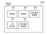
図5は、第1ユーザ端末3の機能ブロック図を示しており、第1ユーザ端末3は、受信
部301、送信部302、記憶装置制御部303、入力受付部304(受付部)、表示装
置制御部305などの機能を有する。なお、図5に示す機能は、CPU300Eが、記憶
装置300Bに記憶されている情報処理プログラムを実行することで実現される。 Fig. 5 shows a functional block diagram of the
受信部301は、例えば、サーバ2から送信されるデータを受信する。The receiving
送信部302は、例えば、入力受付部304で受け付けた入力操作に応じてデータをサ
ーバ2へ送信する。 The transmitting
記憶装置制御部303は、記憶装置300Bを制御する。例えば、記憶装置制御部30
3は、第1ユーザ端末3及び第2ユーザ端末4が送受信したデータなどを、データを送受
信したアカウント又はユーザ端末の識別番号に対応付けて記憶装置300Bに記憶する。
また、記憶装置制御部303は、例えば、第1ユーザ端末3と第2ユーザ端末4との間で
送受信した音声データを記憶装置300Bへ記憶する。 The storage
The
Furthermore, the storage
入力受付部304は、入力装置300Cからの入力操作を受け付ける。The
表示装置制御部305は、表示装置300Dを制御し、例えば、後述する図8~図11
に例示する画面などを表示装置300Dに表示する。 The display
The screen shown in FIG.
(第2ユーザ端末4)
第2ユーザ端末4は、本情報処理システム1の第2ユーザが利用する端末である。第2
ユーザは、第2ユーザ端末4を利用して登録した第1ユーザ端末3と音声データを送受信
することで、第1ユーザ(例えば、自分の家族)と音声によるやりとりをすることができ
る。図6は、第2ユーザ端末4の主なハード構成を示しており、第2ユーザ端末4は、通
信IF400A、記憶装置400B、入力装置400C、表示装置400D(LED)、
CPU400E、マイクロフォン400F、スピーカ400G、GPSセンサ400Hな
どを備える。(Second user terminal 4)
The
The user can communicate with the first user (e.g., his/her family) by voice by transmitting and receiving voice data to and from the registered
The device includes a
通信IF400Aは、他の装置(本実施形態では、サーバ2)と通信するためのインタ
ーフェースである。 The communication IF 400A is an interface for communicating with other devices (in this embodiment, the server 2).
記憶装置400Bは、例えば、HDD(Hard Disk Drive)や半導体記憶装置(SSD(
Solid State Drive))である。記憶装置400Bには、端末の識別番号や情報処理プログ
ラム、第1ユーザ端末3から送信された音声データなどが記憶される。端末の識別番号は
、第2ユーザ端末4を識別するための番号である。第2ユーザ端末4から送信するデータ
に端末の識別番号を付与することで、サーバ2は、受信したデータがどの第2ユーザ端末
4から送信されたものであるかを判定することができる。なお、端末の識別番号は、IP
(Internet Protocol)アドレス、MAC(Media Access Control)アドレスなどを利用
してもよく、サーバ2が第2ユーザ端末4に対して付与するようにしてもよい。 The
The
Alternatively, an Internet Protocol (IP) address, a Media Access Control (MAC) address, or the like may be used, and the
入力装置400Cは、例えば、キーボード、マウス、タッチパネルなどの入力デバイス
であるが、入力可能であれば、他の装置や機器であってもよい。また、音声入力装置であ
ってもよい。第2ユーザは、入力装置400Cを操作して、音声を入力して第1ユーザ端
末3へ送信したり、第1ユーザ端末3から送信された音声データを再生することができる
。 The
表示装置400Dは、例えば、LEDである。表示装置400Dは、後述の報知部40
5により制御され、設定されたパタンや所定のパタンで点灯又は点滅することにより音声
を受信したことを報知する。 The
5 and notifies the reception of voice by lighting or blinking in a set pattern or a predetermined pattern.
CPU400Eは、本実施形態に係る第2ユーザ端末4を制御し、図示しないROM及
びRAMを備える。 The
マイクロフォン400Fは、音を電気信号に変換する音響機器である。第2ユーザ端末
4のユーザは、マイクロフォン400Fを利用して音声を入力することができる。入力さ
れた音声は、後述の送信部402によりサーバ2へ送信される。 The
スピーカ400Gは、電気信号を音に変える音響機器である。スピーカ400Gは、例
えば、サーバ2を介して第1ユーザ端末3から送信され、記憶装置400Bに記憶された
音声データを再生する。また、スピーカ400Gは、後述の報知部405により制御され
、設定されたパタンや所定のパタンで音を発生させることで音声を受信したことを報知す
る。 The
GPSセンサ400Hは、衛星に搭載された原子時計の時刻のデータ、衛星の天体暦(
軌道)などのデータが含まれた信号をGPS衛星から受信し、受信した信号の発信時刻と
受信時刻との差に基づいて衛星からの距離を算出して現在位置を特定する。また、GPS
センサ400Hは、特定した現在位置を出力する。 The
The GPS receives a signal containing data such as the satellite's orbit from a GPS satellite, and calculates the distance from the satellite based on the difference between the time the signal was sent and the time it was received to determine the current position.
The
図7は、第2ユーザ端末4の機能ブロック図を示しており、第2ユーザ端末4は、受信
部401、送信部402、記憶装置制御部403、入力受付部404、報知部405、設
定部406、判定部407(第1~第3判定部)などの機能を有する。なお、図7に示す
機能は、CPU400Eが、記憶装置400Bに記憶されている情報処理プログラムを実
行することで実現される。 7 shows a functional block diagram of the
受信部401は、例えば、サーバ2から送信されるデータ(例えば音声データ)と、デ
ータを受信したことを報知する際の報知パタンを設定する設定指示とを受信する。 The receiving
送信部402は、例えば、入力受付部304で受け付けた入力操作に応じてデータ、例
えば音声データをサーバ2へ送信する。また、送信部402は、判定部に407による判
定結果を(サーバ2を介して)第1ユーザ端末3へ送信する。また、送信部402は、判
定部407による判定結果に応じて、報知部405の報知パタンを所定の報知パタンに設
定することを推奨するための推奨指示を第1ユーザ端末3へ送信する。 The
記憶装置制御部403は、記憶装置400Bを制御する。例えば、記憶装置制御部40
3は、記憶装置400Bを制御してデータの書き込みや読み出しを行う。記憶装置制御部
403は、例えば、受信部401が受信したデータを記憶装置400Bへ記憶する。 The storage
The storage
入力受付部404は、入力装置400Cからの入力操作を受け付ける。入力受付部40
4は、例えば、記憶装置400Bに記憶された音声データの再生操作を受け付ける。 The
4, for example, accepts an operation to play back audio data stored in the
報知部405は、受信部401がデータを受信したことを報知する。報知部405は、
例えば、設定部406が設定した報知パタンに基づいて、表示装置400D(LED)を
点灯又は点滅させたり、スピーカから音を発生させることで受信部401がデータを受信
したことを報知する。 The
For example, based on the notification pattern set by the
設定部406は、受信部401が受信した設定指示に基づいて上記報知部405の報知
パタンを設定する。また、設定部406は、判定部407による判定結果に応じて、報知
部405の報知パタンを所定の報知パタンに設定する。なお、報知パタンには、受信部4
01が受信したデータの再生による報知(第1の報知パタン)が含まれる。この報知パタ
ンの場合、上記報知部405は、受信部401が受信したデータの再生により受信部40
1がデータを受信したことを報知する。 The
In the case of this notification pattern, the
1 notifies that the data has been received.
判定部407は、受信部301が受信したデータの報知に関する状態、例えば、音声デ
ータを再生したかなどを判定する。また、判定部407は、日時、位置、及び第1ユーザ
端末3の属性、の少なくとも1以上が所定条件を満たすか否かを判定する。ここで、日時
は現在日時であり、位置は現在位置であってもよい。 The
(表示画面)
図8~図11は、第1ユーザ端末3の表示装置300Dに表示される画面G1の一例を
示す図である。以下、図8~図11を参照して、第1ユーザ端末3の表示装置300Dに
表示される画面G1の一例について説明する。なお、図1~図7を参照して説明した構成
と同一の構成には同一の符号を付して重複する説明を省略する。(Display screen)
Figures 8 to 11 are diagrams showing an example of a screen G1 displayed on the
図8に示すように、表示装置300Dには、第1ユーザ端末3と第2ユーザ端末4との
間で送受信された音声データが音声ファイル単位で時系列順に表示される(以下、タイム
ライン表示ともいう)。
図8に示す例では、画面G1の上部に第2ユーザの名前11(ハンドルネームでもよい
)が表示される。画面G1の左側には、第2ユーザ端末4から送信された音声データ(第
2ユーザの音声ファイル)を示す表示枠12Bが送信された時刻12D(タイムスタンプ
の情報を利用)及びアイコン12A(第2ユーザを示すアイコン)とともに表示される。
また、再生ボタン12Cを選択(タップ操作)すると表示枠12Bに対応する音声データ
(音声ファイル)が再生され音声を聴くことができる。
また、画面G1の右側には、第1ユーザ端末3から第2ユーザ端末4へ送信された音声
データ(第1ユーザの音声ファイル)を示す表示枠13Aが送信された時刻13C(タイ
ムスタンプの情報を利用)とともに表示される。また、表示枠13Aの近傍には音声デー
タの報知に関する状態13D(例えば、第2ユーザ端末4で音声データを再生したか否か
など)が併記される。また、再生ボタン13Bを選択すると表示枠13Aに対応する音声
データ(音声ファイル)が再生され音声を聴くことができる。
また、画面G1の左側には、第2ユーザ端末4の状態(例えば、時間や位置)に応じて
第2ユーザ端末4又はサーバ2から自動で送信される状況を示すコメント14Bが送信さ
れた時刻14D(タイムスタンプの情報を利用)及びアイコン14A(第2ユーザ端末4
を示すアイコン)とともに表示される。
第1ユーザは、音声データを第2ユーザ端末4へ送信したい場合、タッチパネル等の入
力装置300Cを操作して画面G1下部に表示されたマイクロフォンを模したアイコン1
5を選択する。 As shown in Figure 8, the
8, the
Furthermore, when the
Also, on the right side of the screen G1, a
In addition, on the left side of the screen G1, a
icon indicating that the
When the first user wishes to transmit voice data to the
Select 5.
図9に示す画面G2は、図8を参照して説明したアイコン15を選択(タップ操作)す
ると遷移する画面である。図9に示すように、図8においてアイコン15を選択すると、
第2ユーザ端末4へメッセージを送信するための表示枠16が画面G2の下側からせりあ
がるようにして現れる。第1ユーザは、タッチパネル等の入力装置300Cを操作して画
面G2の表示枠16内に表示されたマイクアイコン16Aを選択することで音声を録音し
て第2ユーザ端末4へ送信することができる。なお、マイクアイコン16Aを選択すると
マイクアイコン16Aの表示形態(例えば、アイコンの色)が変化して録音が始まったこ
とが示される。第1ユーザがメッセージ(例えば、「今から迎えにいくよ」など)を話し
終わり、再度マイクアイコン16Aを再選択するとマイクアイコン16Aの表示形態(例
えば、アイコンの色)が元に戻り録音が終了したことが示される。
また、マイクアイコン16Aの下部には記憶装置300Bにプリセットされていたメッ
セージ16B、第1ユーザが入力したメッセージ16B、サーバ2からダウンロードした
メッセージ16Bなどが複数表示され、第1ユーザは、タッチパネル等の入力装置300
Cを操作して表示された複数のメッセージ16Bのいずれかを選択することで、この選択
したメッセージ16Bを第2ユーザ端末4へ送信することができる。 The screen G2 shown in Fig. 9 is a screen to which the screen transitions when the
A
In addition, below the
By operating C to select one of the multiple displayed
なお、第1ユーザが入力したメッセージには、既に述べたように第1ユーザがマイクロ
フォン300Fを利用して吹き込んだ音声メッセージと、第1ユーザが入力装置300C
を操作してテキストにより入力した文字メッセージとが含まれる。ここで、音声メッセー
ジは文字起こし(テキスト化)されて、音声ファイルのタイトルとして表示される。
図10は、音声メッセージを文字起こし(テキスト化)して音声ファイルのタイトルと
して表示した画面G3の例である。図10に例示するように、画面G3には、音声メッセ
ージを文字起こし(テキスト化)した音声ファイルのメッセージがタイトル16Bとして
表示される。第1ユーザは、タッチパネル等の入力装置300Cを操作して画面G3のボ
イススタンプストア17Aを選択することでサーバ2から音声ファイル(例えば、声優、
俳優、アイドルなどの人が吹き込んだメッセージの音声ファイル、ボーカロイド(登録商
標)などの音声合成エンジンによるメッセージの音声ファイルなど)をダウンロードして
利用することができる。
また、第1ユーザは、タッチパネル等の入力装置300Cを操作してタイトル16Bの
左側に配置された入替ボタン17Bを選択(長押し又はタップ操作など)することでタイ
トル16Bの表示順序を入れ替えることができる。
また、第1ユーザは、タッチパネル等の入力装置300Cを操作してタイトル16Bの
右側に配置された編集ボタン17Cを選択(長押し又はタップ操作など)することでタイ
トル16Bを編集することができる。
また、第1ユーザは、タッチパネル等の入力装置300Cを操作してタイトル16Bの
右側に配置された再生ボタン17Dを選択(長押し又はタップ操作など)することでタイ
トル16Bの元となる音声ファイルを再生(試聴)することができる。
また、第1ユーザは、タッチパネル等の入力装置300Cを操作してタイトル16Bの
右側に配置された録音ボタン17Eを選択(長押し又はタップ操作など)することでタイ
トル16Bの元となる音声ファイルを録音しなおすことができる。
なお、音声ファイルのタイトル16Bは、利用頻度の高い順に表示される設定としても
よい。なお、利用頻度の高い順位表示する場合、メッセージの表記ゆれ(例えばメッセー
ジの類似性など)を考慮してメッセージの利用頻度を算出することが好ましい。 The message input by the first user includes a voice message recorded by the first user using the
and text messages entered by operating the voice message input section. Here, the voice message is transcribed (converted into text) and displayed as the title of the voice file.
10 is an example of a screen G3 on which a voice message is transcribed (converted into text) and displayed as the title of the voice file. As shown in FIG. 10, the screen G3 displays the transcribed (converted into text) voice message as a
You can download and use audio files containing messages recorded by actors, idols, etc., or audio files containing messages generated by voice synthesis engines such as Vocaloid (registered trademark), etc.
In addition, the first user can change the display order of the
In addition, the first user can edit the
In addition, the first user can play (listen to) the audio file that is the source of
In addition, the first user can re-record the audio file that is the source of the
The
また、図9の画面G2に表示されるメッセージ16Bは、第1ユーザによるメッセージ
利用頻度又は第1ユーザによる設定に応じた順序で表示されることが好ましい。例えば、
利用頻度に応じて表示される場合、利用頻度の高い順にメッセージが表示されることが好
ましい。また、図9の画面G2に表示されるメッセージ16Bは、第1ユーザによる設定
に応じた順序で表示されるようにしてもよい。この場合、図10で説明したのと同様に、
第1ユーザが入力装置300Cを操作して手動でメッセージ16Bの表示順序を並べ替え
て設定できるようにしてもよい。また、プリセットされたメッセージ16Bが利用頻度の
高い順に表示される設定としてもよく、第1ユーザが入力したメッセージ16Bが利用頻
度の高い順に表示される設定としてもよい。なお、利用頻度の高い順位表示する場合、メ
ッセージの表記ゆれ(例えばメッセージの類似性など)を考慮してメッセージの利用頻度
を算出することが好ましい。 In addition, it is preferable that the
In the case of displaying messages according to frequency of use, it is preferable that messages are displayed in descending order of frequency of use. Also, the
The first user may operate the
図11に示す画面G4は、図9を参照して説明したマイクアイコン16Aを選択(タッ
プ操作)して音声を録音した後、又はマイクアイコン16Aの下部に表示されたメッセー
ジ16Bを選択すると遷移する画面である。図11に示すように、第1ユーザは、タッチ
パネル等の入力装置300Cを操作して画面G4のアイコン18Aを選択することで録音
した音声を試聴して確認することができる。また、第1ユーザは、タッチパネル等の入力
装置300Cを操作して画面G4のアイコン18Bを選択することで、画面G2に遷移し
、音声を再度録音しなおすことができる。また、第1ユーザは、音声を再度録音しなおす
代わりに遷移した画面G2においてメッセージを選択してもよい。
また、第1ユーザは、第2ユーザ端末4が第1ユーザ端末3からのメッセージを受信し
たことを報知する際の報知パタンを設定することができる。図11に示す例では、第1ユ
ーザは、「着信音ON」19A、「着信音OFF」19B、「この音声を着信音として鳴
らす」19Cから報知パタンを選択することができる。第1ユーザが19A~19Cのい
ずれかを選択すると選択した項目にチェックマークが表示される(図11に示す例では「
着信音ON」19Aが選択されている)。なお、図11に示す例では報知パタンは3つか
ら選択するが、報知パタンは、図11に示す例に限られない。例えば、「着信音ON」1
9Aを選択した場合、着信音を選択できる構成としてもよいし、バイブレーションを報知
パタンとして選択できる構成としてもよい。
第1ユーザが、タッチパネル等の入力装置300Cを操作して画面G4の送信アイコン
18Cを選択すると録音された音声データ又は選択されたメッセージ16Bに対応するデ
ータが、報知パタンの設定指示とともにサーバ2へ送信される。 The screen G4 shown in FIG. 11 is a screen to which the user transitions after selecting (tapping) the
The first user can also set a notification pattern for when the
In the example shown in FIG. 11, the notification pattern is selected from three patterns, but the notification pattern is not limited to the example shown in FIG. 11. For example, "ring tone ON" 19A is selected.
When 9A is selected, a ringtone may be selectable, or vibration may be selectable as the notification pattern.
When the first user operates an
(情報処理)
図12~図15は、情報処理システム1の情報処理の一例を示すフローチャートである
。以下、図12~図15を参照して、情報処理システム1の情報処理について説明する。
なお、図1~図11を参照して説明した構成と同一の構成には同一の符号を付して重複す
る説明を省略する。(Information Processing)
12 to 15 are flowcharts showing an example of information processing by the
The same components as those described with reference to FIGS. 1 to 11 are designated by the same reference numerals and will not be described again.
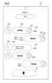
(メッセージ送信処理)
図12は、情報処理システム1のメッセージ送信処理の一例を示すフローチャートであ
る。以下、図12を参照して、情報処理システム1のメッセージ送信処理の一例について
説明する。なお、図12では第2ユーザ端末4から第1ユーザ端末3へ音声データを送信
する場合について説明する。(Message sending process)
Fig. 12 is a flowchart showing an example of a message transmission process of the
(ステップS101)
第2ユーザは、第2ユーザ端末4の入力装置400Cを操作して音声を入力する。(Step S101)
The second user operates the
(ステップS102)
入力された音声は、マイクロフォン400Fにより電気信号に変換されたのち音声デー
タとして送信部402からサーバ2へ送信される。なお、第2ユーザ端末4から送信され
るデータには、第2ユーザ端末4の識別番号、タイムスタンプなどのデータが付与されて
いる。(Step S102)
The input voice is converted into an electric signal by the
(ステップS103)
サーバ2の受信部201は、第2ユーザ端末4から送信された音声データを受信する。(Step S103)
The receiving
(ステップS104)
サーバ2の記憶装置制御部203は、第2ユーザ端末4が送信した音声データを、デー
タを送受信したアカウント又はユーザ端末の識別番号に対応付けて記憶装置200Bに記
憶する。(Step S104)
The storage
(ステップS105)
サーバ2の送信部202は、記憶装置200Bを参照し、受信部201が受信した音声
データに付与された識別番号に対応付けされた第1ユーザ端末3の識別番号を特定し、特
定した第1ユーザ端末3へ第2ユーザ端末4から送信された音声データを送信する。(Step S105)
The transmitting
(ステップS106)
第1ユーザ端末3の受信部301は、サーバ2から送信された音声データを受信する。(Step S106)
The receiving
(ステップS107)
第1ユーザ端末3の報知部311は、音声を受信したことを報知する。(Step S107)
The notification unit 311 of the
(メッセージ送信処理)
図13は、情報処理システム1のメッセージ送信処理の一例を示すフローチャートであ
る。以下、図13を参照して、情報処理システム1のメッセージ送信処理の一例について
説明する。なお、図13では第1ユーザ端末3から第2ユーザ端末4へ音声データを送信
する場合について説明する。(Message sending process)
Fig. 13 is a flowchart showing an example of a message transmission process of the
(ステップS201)
第1ユーザは、第1ユーザ端末3の入力装置300Cを操作して第2ユーザ端末4へ送
信するメッセージ及び報知パタンの設定指示を入力する。この入力操作については後述す
る。(Step S201)
The first user operates the
(ステップS202)
第1ユーザ端末3の送信部302は、入力された入力データをサーバ2へ送信する。な
お、第1ユーザ端末3から送信される入力データには、第1ユーザ端末3の識別番号、タ
イムスタンプなどのデータが付与されている。(Step S202)
The transmitting
(ステップS203)
サーバ2の受信部201は、第1ユーザ端末3から送信された入力データを受信する。(Step S203)
The receiving
(ステップS204)
サーバ2の記憶装置制御部203は、第1ユーザ端末3が送信した入力データのうち音
声データを、データを送受信したアカウント又はユーザ端末の識別番号に対応付けて記憶
装置200Bに記憶する。(Step S204)
The storage
(ステップS205)
サーバ2の送信部202は、記憶装置200Bを参照し、受信部201が受信した音声
データに付与された識別番号に対応付けされた第2ユーザ端末4の識別番号を特定し、特
定した第2ユーザ端末4へ第1ユーザ端末3から送信された入力データを送信する。(Step S205)
The transmitting
(ステップS206)
第2ユーザ端末4の受信部401は、サーバ2から送信された入力データを受信する。(Step S206)
The receiving
(ステップS207)
第2ユーザ端末4の設定部406は、報知パタンを設定する。設定部406による報知
パタンの設定は後述する。(Step S207)
The
(ステップS208)
第2ユーザ端末4の報知部405は、設定部406が設定した報知パタンでデータを受
信したことを報知する。報知部405は、設定部406が設定した報知パタンに基づいて
、表示装置(LED)の点灯又は点滅、音、バイブレーションなどによりメッセージを受
信したことを報知する。(Step S208)
The
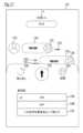
(入力処理)
図14は、図13のステップS201の入力処理の一例を示すフローチャートである。
以下、図14を参照して、図13のステップS201の入力処理の一例について説明する
。(Input Processing)
FIG. 14 is a flowchart showing an example of the input process in step S201 of FIG.
An example of the input process in step S201 in FIG. 13 will be described below with reference to FIG.
(ステップS301)
第1ユーザは、第1ユーザ端末3の入力装置300Cを操作して図9で説明した画面G
2又は図10で説明した画面G3を表示させる。第1ユーザ端末3の表示装置制御部30
5は画面G2又は画面G3を表示装置300Dに表示させる。(Step S301)
The first user operates the
2 or the screen G3 described in FIG. 10.
5 causes the
(ステップS302)
第1ユーザ端末3の入力受付部304は、入力装置300Cを操作して画面G2又は画
面G3に表示されたメッセージ16Bのいずれかが選択されたかを判定する。メッセージ
16Bのいずれかが選択されている場合(YES)、第1ユーザ端末3は、ステップS3
05の処理を実行する。メッセージが選択されていない場合(NO)、第1ユーザ端末3
は、ステップS303の処理を実行する。(Step S302)
The
If no message is selected (NO), the
executes the process of step S303.
(ステップS303)
第1ユーザ端末3の入力受付部304は、入力装置300Cを操作して画面G2又は画
面G3に表示されたマイクアイコン16Aが選択されたかを判定する。マイクアイコン1
6Aが選択された場合(YES)、第1ユーザ端末3は、ステップS304の処理を実行
する。マイクアイコン16Aが選択されていない場合(NO)、第1ユーザ端末3は、ス
テップS302の処理へ戻る。(Step S303)
The
If the
(ステップS304)
第1ユーザ端末3は、マイクロフォンを利用して入力された第1ユーザの音声を録音す
る。例えば、第1ユーザ端末3の記憶装置制御部303は、マイクロフォンを利用して入
力された第1ユーザの音声を記憶装置300Bに記憶する。(Step S304)
The
なお、ステップS302の処理と、ステップS303及びステップS304の処理との
順序は逆であってもよい。 The order of the process of step S302 and the processes of steps S303 and S304 may be reversed.
(ステップS305)
第1ユーザ端末3の表示装置制御部305は、図11で説明した画面G4を表示装置3
00Dに表示させる。第1ユーザ端末3の入力受付部304は、第1ユーザが入力装置3
00Cを操作して入力された報知パタンを受け付ける。(Step S305)
The display
The
The notification pattern input by operating 00C is accepted.
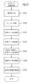
(報知パタン設定処理)
図15は、図13のステップS207の報知パタン設定処理の一例を示すフローチャー
トである。以下、図15を参照して、図13のステップS207の報知パタン設定処理の
一例について説明する。(Notification pattern setting process)
Fig. 15 is a flowchart showing an example of the notification pattern setting process in step S207 in Fig. 13. Hereinafter, an example of the notification pattern setting process in step S207 in Fig. 13 will be described with reference to Fig. 15.
(ステップS401)
第2ユーザ端末4の判定部407は、日時、位置、及び第1ユーザ端末3の属性、の少
なくとも1以上が所定条件を満たすか否かを判定する。所定条件を満たす場合(YES)
、第2ユーザ端末4は、ステップS402の処理を実行する。所定条件を満たさない場合
(NO)、第2ユーザ端末4は、ステップS403の処理を実行する。(Step S401)
The
If the predetermined condition is not satisfied (NO), the
(ステップS402)
第2ユーザ端末4の設定部406は、受信部401が受信した設定指示に基づいて上記
報知部405の報知パタンを設定する。(Step S402)
The
(ステップS403)
第2ユーザ端末4の送信部402は、報知部405の報知パタンを所定の報知パタンに
設定することを(サーバ2を介して)第1ユーザ端末3へ送信する。(Step S403)
The transmitting
(ステップS404)
第2ユーザ端末4の設定部406は、報知部405の報知パタンを所定の報知パタンに
設定する。(Step S404)
The
なお、上記説明では、日時、位置、及び第1ユーザ端末3の属性、の少なくとも1以上
が所定条件を満たさない場合、報知部405の報知パタンを所定の報知パタンに設定して
いるが、判定部407は、日時、位置、並びに異なる端末の属性及びステータス、の少な
くとも1以上が所定条件を満たすか否かを判定し、日時、位置、及び第1ユーザ端末3の
属性、の少なくとも1以上が所定条件を満たさない場合、報知部405の報知パタンを所
定の報知パタンに設定することを推奨し、この推奨指示を第1ユーザ端末3へ送信し、第
1ユーザ端末3から許可信号を受信した場合に、設定部406が報知部405の報知パタ
ンを所定の報知パタンに設定する構成としてもよい。 In the above description, if at least one of the date and time, the location, and the attributes of the
以上のように、第2ユーザ端末4は、データ(例えば、音声データ)と、データを受信
したことを報知する際の報知パタンを設定する設定指示とを異なる端末から受信する受信
部401と、受信部401がデータを受信したことを報知する報知部405と、設定指示
に基づいて報知部の報知パタンを設定する設定部406とを備える。
通常、携帯端末では、端末の報知の設定は該端末の所持者がその状況等にあわせて行う
ものであり、メッセージの送信者などの第三者が設定できる仕様にはなってないが、上記
のように、本発明では、異なる端末である第1ユーザ端末3からデータ受信の報知パタン
を設定することができるため利便性が高い。例えば、学校や塾の授業中にメッセージの着
信が音などにより報知されると迷惑となる恐れがある一方、常に無音にしておくと第2ユ
ーザがいつまでもメッセージに気づかない恐れがあるが、第2ユーザ端末4の報知パタン
を変更することができるため、上記のような問題を解決することができる。 As described above, the
Normally, in a mobile terminal, the terminal notification settings are set by the owner of the terminal according to the situation, etc., and are not designed to be configurable by a third party such as the sender of a message, but as described above, the present invention is highly convenient because the notification pattern for data reception can be set from a different terminal, the
また、第2ユーザ端末4は、受信部401が受信したデータの報知に関する状態を判定
する判定部407と、判定部407による判定結果を異なる端末である第1ユーザ端末3
へ送信する送信部402とを備える。
このように、第2ユーザ端末4のデータの報知に関する状態(例えば、メッセージを聴
いたか聴いていないかなど)を第1ユーザ端末3へ送信するので、第2ユーザ(例えば、
子供)がメッセージを聴いているか否かを第1ユーザ端末3で確認できるので利便性が向
上する。
このように、第2ユーザ端末4の日時(例えば、学校や塾の時間であるか否か)、位置
(例えば、学校や塾に居る否か)、及び異なる端末である第1ユーザ端末3の属性(親で
あるか、兄弟であるか、祖父母であるかなど)、の少なくとも1以上が所定条件を満たす
か否かを判定し、条件を満たさない場合、例えば、学校や塾の時間である場合、学校や塾
に居る場合、第1ユーザ端末3の属性が親以外である場合には、報知部405の報知パタ
ンを所定の報知パタンに設定することを推奨するための推奨指示を、異なる端末である第
1ユーザ端末3へ送信するなどできるので利便性が向上する。 In addition, the
and a transmitting
In this way, the state of the
Since it is possible to check at the
In this way, it is determined whether at least one of the date and time of the second user terminal 4 (e.g., whether it is school or cram school time), the location (e.g., whether the user is at school or cram school), and the attribute of the
また、第2ユーザ端末4は、日時、位置、並びに異なる端末の属性及びステータス、の
少なくとも1以上が所定条件を満たすか否かを判定する判定部407を備え、設定部40
6は、判定部407による判定結果に応じて、報知部の報知パタンを所定の報知パタンに
設定する。
このように、第2ユーザ端末4の日時(例えば、学校や塾の時間であるか否か)、位置
(例えば、学校や塾に居る否か)、及び異なる端末である第1ユーザ端末3の属性(親で
あるか、兄弟であるか、祖父母であるかなど)、の少なくとも1以上が所定条件を満たす
か否かを判定し、例えば、学校や塾の時間である場合、学校や塾に居る場合、第1ユーザ
端末3の属性が親以外である場合には、報知部405の報知パタンを所定の報知パタンに
設定するなどできるので利便性が向上する。 The
The notification pattern of the notification unit 6 is set to a predetermined notification pattern in accordance with the result of the determination by the
In this way, it is determined whether at least one of the date and time of the second user terminal 4 (for example, whether it is school or cram school time), the location (for example, whether the user is at school or cram school), and the attribute of the
なお、第2ユーザ端末4は、日時、位置、並びに異なる端末の属性及びステータス、の
少なくとも1以上が所定条件を満たすか否かを判定する判定部407と、判定部407に
よる判定結果に応じて、報知部405の報知パタンを所定の報知パタンに設定することを
推奨するための推奨指示を異なる端末である第1ユーザ端末3へ送信する送信部402と
を備えるようにしてもよい。 In addition, the
また、日時は現在日時であること、又は位置が現在位置であることのいずれか又はその
双方であることが好ましい。日時は現在日時であること、又は位置が現在位置であること
のいずれか又はその双方とすることで、今現在、第2ユーザが、例えば、学校や塾の時間
であるか否か、学校や塾に居る否かを判定することができる。 In addition, it is preferable that the date and time is the current date and time, or the location is the current location, or both. By setting the date and time to the current date and time, or the location to the current location, or both, it is possible to determine whether the second user is currently at school or cram school, for example.
また、本実施形態では、報知パタンは第1の報知パタンとしてデータの再生による報知
を含み、報知部405は、第1の報知パタンで設定された設定指示を受信部401が受信
した場合、データの再生によりデータを受信したことを報知する。
このように、メッセージの再生をもって報知とすることができるので利便性が向上する
。 In addition, in this embodiment, the notification pattern includes a notification by data playback as a first notification pattern, and when the receiving
In this way, the message can be reproduced as a notification, which improves convenience.
なお、本実施形態では、第2ユーザ端末4の受信部401は、サーバ2(情報処理装置
)を介して異なる端末である第1ユーザ端末3からデータと、設定指示とを受信している
が、第1ユーザ端末3と第2ユーザ端末4とがサーバ2(情報処理装置)を介さずに(例
えばピアトゥピアなどの方式により)データ(例えば、音声データ)と、設定指示とを送
受信するようにしてもよい。 In this embodiment, the receiving
[実施形態の変形例1]
なお、上記実施形態において、第1ユーザ端末3に音声データをテキストデータ(文字
データ)化するテキスト化部を備え、第1ユーザ端末3と第2ユーザ端末4との間で送受
信した音声データの少なくとも一部をテキスト化したテキストデータを表示装置300D
に表示(出力)するようにしてもよい。音声を文字で確認できるため、利便性が向上する
。
また、第2ユーザ端末4へ送信した音声データを変換した文字データを、図9を参照し
て説明したメッセージ16Bとして画面G2にて表示(出力)するように構成してもよい
。この場合においても、メッセージ16B(テキストデータ)は、第1ユーザによるメッ
セージの利用頻度又は第1ユーザによる設定に応じた順序で表示されることが好ましい。[First Modification of the Embodiment]
In the above embodiment, the
The voice can be confirmed as text, which improves convenience.
Also, the voice data transmitted to the
[実施形態の変形例2]
また、第1ユーザ端末3が有する機能の少なくとも一部をサーバ2が有するようにして
もよい。例えば、上述した第1ユーザ端末3と第2ユーザ端末4との間で送受信した音声
データの少なくとも一部を文字データにテキスト化するテキスト化部をサーバ2に備える
ようにしてもよい。また、この場合、メッセージ16B(テキストデータ)は、第1ユー
ザによるメッセージの利用頻度又は第1ユーザによる設定に応じた順序をサーバで判定す
ることにより、第1ユーザ端末3にてメッセージ16B(テキストデータ)が第1ユーザ
によるメッセージ利用頻度又は第1ユーザによる設定に応じた順序で表示(出力)される
構成としてもよい。[
The
また、図7に示す第2ユーザ端末4が有する機能の少なくとも一部をサーバ2が有する
ようにしてもよい。例えば、第2ユーザ端末4が有する機能のうち判定部407の機能を
サーバ2が有するようにしてもよい。この場合、データの報知に関する状態や、日時、位
置、並びに異なる端末の属性及びステータス、の少なくとも1以上が所定条件を満たすか
否かはサーバ2で判定される。 7 may be included in the
また、図7に示す第2ユーザ端末4が有する機能の少なくとも一部をサーバ2又は第1
ユーザ端末3が有するようにしてもよい。例えば、第2ユーザ端末4が有する機能のうち
判定部407の機能や、報知部405の報知パタンを所定の報知パタンに設定することを
推奨する機能(推奨部)をサーバ2又は第1ユーザ端末3が有するようにしてもよい。こ
の場合、データの報知に関する状態や、日時、位置、並びに異なる端末の属性及びステー
タス、の少なくとも1以上が所定条件を満たすか否かはサーバ2又は第1ユーザ端末3で
判定される。 In addition, at least a part of the functions of the
The
その他、上記実施形態及び変形例は、何れも本発明を実施するにあたっての具体化の一
例を示したものに過ぎず、これによって本発明の技術的範囲が限定的に解釈されてはなら
ないものである。すなわち、本発明はその要旨、またはその主要な特徴から逸脱すること
なく、様々な形で実施することができる。 In addition, the above-mentioned embodiment and modifications are merely examples of the embodiment of the present invention, and the technical scope of the present invention should not be interpreted as being limited thereby. In other words, the present invention can be embodied in various forms without departing from the gist or main characteristics thereof.
1 情報処理システム
2 サーバ(情報処理装置)
200A 通信IF
200B 記憶装置
200C CPU
201 受信部
202 送信部
203 記憶装置制御部
3 第1ユーザ端末(情報処理端末)
300A 通信IF
300B 記憶装置
300C 入力装置
300D 表示装置
300E CPU
300F マイクロフォン
300G スピーカ
301 受信部
302 送信部
303 記憶装置制御部
304 入力受付部(受付部)
305 表示装置制御部
4 第2ユーザ端末
400A 通信IF
400B 記憶装置
400C 入力装置
400D 表示装置(LED)
400E CPU
400F マイクロフォン
400G スピーカ
400H GPSセンサ
401 受信部
402 送信部
403 記憶装置制御部
404 入力受付部
405 報知部
406 設定部
407 判定部
5 ネットワーク1
200A Communication IF
201
300A Communication IF
305 Display
400E CPU
Claims (15)
Translated fromJapanese前記被見守り者用端末からの第1音声データと、前記被見守り者用端末の位置の履歴を表示させるための位置情報と、を受信する受信部、
前記第1音声データを出力する音声出力制御部、
前記被見守り者用端末に送信される、前記見守り者用端末のマイクに入力された音声を第2音声データとして送信する送信部、
前記第1音声データの再生時間、前記第1音声データの送信時刻、または、前記第1音声データの存在を示す表示を含む時系列表示画面を表示させる表示装置制御部、として機能させるプログラム。 A monitoring system for transmitting location information of a terminal for a person being watched to a terminal for a watcher,
a receiving unit that receives first voice data from the watched-over person terminal and location information for displaying a location history of the watched-over person terminal;
an audio output control unit that outputs the first audio data;
a transmitting unit that transmits, to the watched-over person terminal, a voice input to a microphone of the watching-over terminal as second voice data;
A program that functions as a display device control unit that displays a time series display screen including an indication of the playback time of the first audio data, the transmission time of the first audio data, or the presence of the first audio data.
前記時系列表示画面に、前記見守り者用端末のマイクに対する音声の入力を受け付けるための第1アイコンを表示させ、
音声の入力を受け付けた後に、受け付けた音声を試聴するための第2アイコンを表示させる、請求項1乃至6のいずれかに記載のプログラム。 The display device control unit is
displaying a first icon for receiving voice input to a microphone of the watcher terminal on the time series display screen;
7. The program according to claim 1, further comprising: after accepting an input of a voice, displaying a second icon for previewing the accepted voice.
前記被見守り者用端末からの第1音声データと、前記被見守り者用端末の位置の履歴を表示させるための位置情報と、を受信するステップと、
前記第1音声データを出力するステップと、
前記被見守り者用端末に送信される、前記見守り者用端末のマイクに入力された音声を第2音声データとして送信するステップと、
前記第1音声データの再生時間、前記第1音声データの送信時刻、または、前記第1音声データの存在を示す表示を含む時系列表示画面を表示させるステップと、を含む音声データの処理方法。 A monitoring system for transmitting location information of a device for a person being watched to a device for a watcher,
receiving first voice data from the watched-over person terminal and location information for displaying a location history of the watched-over person terminal;
outputting the first audio data;
a step of transmitting, as second voice data, a voice input to a microphone of the watcher terminal, the voice being transmitted to the watched-over person terminal;
A method for processing audio data, comprising the step of displaying a time series display screen including an indication of the playback time of the first audio data, the transmission time of the first audio data, or the presence of the first audio data.
前記被見守り者用端末からの第1音声データと、前記被見守り者用端末の位置の履歴を表示させるための位置情報と、を受信する受信部、
前記第1音声データを出力する音声出力制御部、
前記被見守り者用端末に送信される、前記見守り者用端末のマイクに入力された音声を第2音声データとして送信する送信部、および、
前記第1音声データの再生時間、前記第1音声データの送信時刻、または、前記第1音声データの存在を示す表示を含む時系列表示画面を表示させる表示装置制御部を備える見守り者用端末。 A watcher terminal in a monitoring system that transmits location information of a watched person terminal to a watcher terminal,
a receiving unit that receives first voice data from the watched-over person terminal and location information for displaying a location history of the watched-over person terminal;
an audio output control unit that outputs the first audio data;
a transmitting unit configured to transmit, as second voice data, a voice input to a microphone of the watcher terminal, which is to be transmitted to the watched-over person terminal; and
A terminal for a monitor that is equipped with a display device control unit that displays a time series display screen including an indication of the playback time of the first audio data, the transmission time of the first audio data, or the presence of the first audio data.
前記被見守り者用端末からの第1音声データを前記被見守り者用端末から受信し、前記見守り者用端末からの第2音声データを前記見守り者用端末から受信する受信部、
前記第1音声データと、前記被見守り者用端末の時間および/または位置に関する情報を含むコメントを表示させるためのデータと、を前記見守り者用端末に送信し、前記第2音声データを前記被見守り者用端末に送信する送信部、として機能させるプログラム。 A server in a monitoring system that transmits location information of a device for a person being watched to a device for a watcher,
a receiving unit that receives first voice data from the watched-over person terminal and receives second voice data from the watcher terminal;
A program that functions as a transmitting unit that transmits the first audio data and data for displaying a comment including information regarding the time and/or location of the terminal for the person being watched over to the terminal for the watcher, and transmits the second audio data to the terminal for the person being watched over.
前記被見守り者用端末からの第1音声データを前記被見守り者用端末から受信し、前記見守り者用端末からの第2音声データを前記見守り者用端末から受信するステップと、
前記第1音声データと、前記被見守り者用端末の時間および/または位置に関する情報を含むコメントを表示させるためのデータと、を前記見守り者用端末に送信し、前記第2音声データを前記被見守り者用端末に送信するステップと、を含む音声データの処理方法。 A server in a monitoring system that transmits location information of a device for a person being watched to a device for a watcher,
receiving first voice data from the watched-over person terminal and receiving second voice data from the watching-over person terminal;
A method for processing audio data, comprising the steps of transmitting the first audio data and data for displaying a comment including information regarding the time and/or location of the terminal for the person being watched over to the terminal for the watcher, and transmitting the second audio data to the terminal for the person being watched over.
前記被見守り者用端末からの第1音声データを前記被見守り者用端末から受信し、前記見守り者用端末からの第2音声データを前記見守り者用端末から受信する受信部、および、
前記第1音声データと、前記被見守り者用端末の時間および/または位置に関する情報を含むコメントを表示させるためのデータと、を前記見守り者用端末に送信し、前記第2音声データを前記被見守り者用端末に送信する送信部を備えるサーバ。 A server in a monitoring system that transmits location information of a terminal for a person being watched to a terminal for a watcher,
a receiving unit that receives first voice data from the watched-over person terminal and receives second voice data from the watching-over person terminal; and
A server having a transmitting unit that transmits the first audio data and data for displaying a comment including information regarding the time and/or location of the terminal for the person being watched over to the terminal for the watcher, and transmits the second audio data to the terminal for the person being watched over.
Priority Applications (4)
| Application Number | Priority Date | Filing Date | Title |
|---|---|---|---|
| JP2024084223AJP7525971B1 (en) | 2022-02-25 | 2024-05-23 | Information processing terminal, information processing device, information processing method, and information processing program |
| JP2024111442AJP7664663B2 (en) | 2022-02-25 | 2024-07-11 | Information processing terminal, information processing device, information processing method, and information processing program |
| JP2025060470AJP7705688B1 (en) | 2022-02-25 | 2025-04-01 | Information processing terminal, information processing device, information processing method, and information processing program |
| JP2025105256AJP2025134895A (en) | 2022-02-25 | 2025-06-23 | Information processing terminal, information processing device, information processing method, and information processing program |
Applications Claiming Priority (4)
| Application Number | Priority Date | Filing Date | Title |
|---|---|---|---|
| PCT/JP2022/007831WO2023162120A1 (en) | 2022-02-25 | 2022-02-25 | Information processing terminal, information processing device, information processing method, and information processing program |
| JP2023577842AJP7489152B2 (en) | 2022-02-25 | 2022-02-25 | Information processing terminal, information processing device, information processing method, and information processing program |
| JP2024071075AJP7525968B1 (en) | 2022-02-25 | 2024-04-25 | Information processing terminal, information processing device, information processing method, and information processing program |
| JP2024084223AJP7525971B1 (en) | 2022-02-25 | 2024-05-23 | Information processing terminal, information processing device, information processing method, and information processing program |
Related Parent Applications (1)
| Application Number | Title | Priority Date | Filing Date |
|---|---|---|---|
| JP2024071075ADivisionJP7525968B1 (en) | 2022-02-25 | 2024-04-25 | Information processing terminal, information processing device, information processing method, and information processing program |
Related Child Applications (1)
| Application Number | Title | Priority Date | Filing Date |
|---|---|---|---|
| JP2024111442ADivisionJP7664663B2 (en) | 2022-02-25 | 2024-07-11 | Information processing terminal, information processing device, information processing method, and information processing program |
Publications (2)
| Publication Number | Publication Date |
|---|---|
| JP7525971B1 JP7525971B1 (en) | 2024-07-31 |
| JP2024109831Atrue JP2024109831A (en) | 2024-08-14 |
Family
ID=87765002
Family Applications (7)
| Application Number | Title | Priority Date | Filing Date |
|---|---|---|---|
| JP2023577842AActiveJP7489152B2 (en) | 2022-02-25 | 2022-02-25 | Information processing terminal, information processing device, information processing method, and information processing program |
| JP2024071075AActiveJP7525968B1 (en) | 2022-02-25 | 2024-04-25 | Information processing terminal, information processing device, information processing method, and information processing program |
| JP2024084223AActiveJP7525971B1 (en) | 2022-02-25 | 2024-05-23 | Information processing terminal, information processing device, information processing method, and information processing program |
| JP2024111442AActiveJP7664663B2 (en) | 2022-02-25 | 2024-07-11 | Information processing terminal, information processing device, information processing method, and information processing program |
| JP2024111734AActiveJP7664664B2 (en) | 2022-02-25 | 2024-07-11 | Information processing terminal, information processing device, information processing method, and information processing program |
| JP2025060470AActiveJP7705688B1 (en) | 2022-02-25 | 2025-04-01 | Information processing terminal, information processing device, information processing method, and information processing program |
| JP2025105256APendingJP2025134895A (en) | 2022-02-25 | 2025-06-23 | Information processing terminal, information processing device, information processing method, and information processing program |
Family Applications Before (2)
| Application Number | Title | Priority Date | Filing Date |
|---|---|---|---|
| JP2023577842AActiveJP7489152B2 (en) | 2022-02-25 | 2022-02-25 | Information processing terminal, information processing device, information processing method, and information processing program |
| JP2024071075AActiveJP7525968B1 (en) | 2022-02-25 | 2024-04-25 | Information processing terminal, information processing device, information processing method, and information processing program |
Family Applications After (4)
| Application Number | Title | Priority Date | Filing Date |
|---|---|---|---|
| JP2024111442AActiveJP7664663B2 (en) | 2022-02-25 | 2024-07-11 | Information processing terminal, information processing device, information processing method, and information processing program |
| JP2024111734AActiveJP7664664B2 (en) | 2022-02-25 | 2024-07-11 | Information processing terminal, information processing device, information processing method, and information processing program |
| JP2025060470AActiveJP7705688B1 (en) | 2022-02-25 | 2025-04-01 | Information processing terminal, information processing device, information processing method, and information processing program |
| JP2025105256APendingJP2025134895A (en) | 2022-02-25 | 2025-06-23 | Information processing terminal, information processing device, information processing method, and information processing program |
Country Status (5)
| Country | Link |
|---|---|
| US (1) | US20250175552A1 (en) |
| EP (1) | EP4485914A1 (en) |
| JP (7) | JP7489152B2 (en) |
| CN (1) | CN118749193A (en) |
| WO (1) | WO2023162120A1 (en) |
Families Citing this family (1)
| Publication number | Priority date | Publication date | Assignee | Title |
|---|---|---|---|---|
| JP7523830B1 (en)* | 2023-10-20 | 2024-07-29 | ビーサイズ株式会社 | Information processing device, information processing terminal, information processing method, and information processing program |
Citations (4)
| Publication number | Priority date | Publication date | Assignee | Title |
|---|---|---|---|---|
| JP2016531498A (en)* | 2013-08-02 | 2016-10-06 | ワッツアップ・インコーポレイテッドWhatsapp Inc. | Voice communication using real-time status notification |
| JP2017521804A (en)* | 2014-05-31 | 2017-08-03 | アップル インコーポレイテッド | Message user interface for capture and transmission of media and location content |
| JP2019041353A (en)* | 2017-08-29 | 2019-03-14 | 京セラ株式会社 | Electronic apparatus and system |
| JP2020048093A (en)* | 2018-09-20 | 2020-03-26 | 株式会社 ゼネテック | Information transmission system and location information server |
Family Cites Families (16)
| Publication number | Priority date | Publication date | Assignee | Title |
|---|---|---|---|---|
| JP2000236568A (en)* | 1999-02-15 | 2000-08-29 | Toyo Commun Equip Co Ltd | Pocket bell system |
| JP2002149561A (en)* | 2000-11-10 | 2002-05-24 | Nec Telecom Syst Ltd | Portable telephone having read transmission mail confirmation function, portable telephone system having read transmission mail confirmation function and method for confirming read transmission mail |
| JP2002176673A (en)* | 2000-12-05 | 2002-06-21 | Matsushita Electric Ind Co Ltd | Digital radio system |
| JP2003008686A (en)* | 2001-06-25 | 2003-01-10 | Mitsubishi Electric Corp | Terminals, communication data reception method at terminals, and program for reception of communication data at terminals |
| JP2005020225A (en)* | 2003-06-25 | 2005-01-20 | Casio Comput Co Ltd | Communication terminal apparatus and communication control processing program thereof |
| JP2006115124A (en)* | 2004-10-13 | 2006-04-27 | Nec Commun Syst Ltd | Mobile phone system, mail transmission / reception method, and mobile phone device |
| JP4946589B2 (en)* | 2007-04-18 | 2012-06-06 | 株式会社ナカヨ通信機 | Telephone system having incoming call notification selection function and incoming call notification method management apparatus |
| JP5397720B1 (en) | 2013-04-26 | 2014-01-22 | 株式会社Kpiソリューションズ | Program, information processing terminal, and information processing method |
| JP6069373B2 (en)* | 2015-01-05 | 2017-02-01 | 京セラドキュメントソリューションズ株式会社 | Mobile terminal and incoming call operation control program |
| JP2018142287A (en)* | 2017-02-28 | 2018-09-13 | 株式会社ネイン | Messaging system |
| US10812423B2 (en)* | 2017-03-15 | 2020-10-20 | Naver Corporation | Method, apparatus, system, and non-transitory computer readable medium for chatting on mobile device using an external device |
| JP2019204300A (en) | 2018-05-24 | 2019-11-28 | 京セラドキュメントソリューションズ株式会社 | Monitoring system |
| JP6832971B2 (en)* | 2019-03-19 | 2021-02-24 | Line株式会社 | Programs, information processing methods, terminals |
| US11620896B1 (en) | 2020-02-20 | 2023-04-04 | Otta Inc. | Location information sharing control system and location information sharing control device |
| JP7353216B2 (en)* | 2020-02-28 | 2023-09-29 | 株式会社東芝 | communication system |
| US11798388B2 (en) | 2020-05-11 | 2023-10-24 | Otta Inc. | Location positioning system |
- 2022
- 2022-02-25JPJP2023577842Apatent/JP7489152B2/enactiveActive
- 2022-02-25USUS18/841,002patent/US20250175552A1/enactivePending
- 2022-02-25EPEP22928647.1Apatent/EP4485914A1/enactivePending
- 2022-02-25CNCN202280092432.2Apatent/CN118749193A/enactivePending
- 2022-02-25WOPCT/JP2022/007831patent/WO2023162120A1/ennot_activeCeased
- 2024
- 2024-04-25JPJP2024071075Apatent/JP7525968B1/enactiveActive
- 2024-05-23JPJP2024084223Apatent/JP7525971B1/enactiveActive
- 2024-07-11JPJP2024111442Apatent/JP7664663B2/enactiveActive
- 2024-07-11JPJP2024111734Apatent/JP7664664B2/enactiveActive
- 2025
- 2025-04-01JPJP2025060470Apatent/JP7705688B1/enactiveActive
- 2025-06-23JPJP2025105256Apatent/JP2025134895A/enactivePending
Patent Citations (4)
| Publication number | Priority date | Publication date | Assignee | Title |
|---|---|---|---|---|
| JP2016531498A (en)* | 2013-08-02 | 2016-10-06 | ワッツアップ・インコーポレイテッドWhatsapp Inc. | Voice communication using real-time status notification |
| JP2017521804A (en)* | 2014-05-31 | 2017-08-03 | アップル インコーポレイテッド | Message user interface for capture and transmission of media and location content |
| JP2019041353A (en)* | 2017-08-29 | 2019-03-14 | 京セラ株式会社 | Electronic apparatus and system |
| JP2020048093A (en)* | 2018-09-20 | 2020-03-26 | 株式会社 ゼネテック | Information transmission system and location information server |
Also Published As
| Publication number | Publication date |
|---|---|
| JP7489152B2 (en) | 2024-05-23 |
| WO2023162120A1 (en) | 2023-08-31 |
| JP7705688B1 (en) | 2025-07-17 |
| JP7525968B1 (en) | 2024-07-31 |
| JP2024138439A (en) | 2024-10-08 |
| CN118749193A (en) | 2024-10-08 |
| JP2025134895A (en) | 2025-09-17 |
| JPWO2023162120A1 (en) | 2023-08-31 |
| JP7664663B2 (en) | 2025-04-18 |
| JP7664664B2 (en) | 2025-04-18 |
| JP2024106995A (en) | 2024-08-08 |
| JP7525971B1 (en) | 2024-07-31 |
| JP2025110410A (en) | 2025-07-28 |
| US20250175552A1 (en) | 2025-05-29 |
| EP4485914A1 (en) | 2025-01-01 |
| JP2024138454A (en) | 2024-10-08 |
Similar Documents
| Publication | Publication Date | Title |
|---|---|---|
| JP7705688B1 (en) | Information processing terminal, information processing device, information processing method, and information processing program | |
| JP4363166B2 (en) | Communication service providing system, server, service providing method, and service providing program | |
| CN101098334B (en) | Information processing device and information processing method | |
| JPH0965224A (en) | TV receiver | |
| JP7747389B2 (en) | Information processing device, information processing terminal, information processing method, and information processing program | |
| JP6610076B2 (en) | Information processing apparatus, information processing system, program, and recording medium | |
| JP6724188B2 (en) | Server, server control method, and program | |
| JP2008199202A (en) | IP telephone system and voice mail control method | |
| JP7508156B2 (en) | Information processing terminal, information processing method, and information processing program | |
| JP7533492B2 (en) | Karaoke program and karaoke device | |
| JP7619290B2 (en) | Karaoke program and karaoke device | |
| JP2011142523A (en) | Device, system and program for support of presentation, and recording medium | |
| JP4494088B2 (en) | Chat program and computer | |
| JP2004246777A (en) | Information transmission system and information processing device and program for the system | |
| JP2020161182A (en) | Server, server control method, and program | |
| JP2007312143A (en) | Telephone equipment | |
| JP2014071168A (en) | Music evaluation device, and program for music evaluation | |
| JP2007179334A (en) | Information processor, information processing method, program and recording medium | |
| JP2014191142A (en) | Karaoke device | |
| WO2013114472A1 (en) | Communication device, operation method thereof, and operation program thereof |
Legal Events
| Date | Code | Title | Description |
|---|---|---|---|
| A621 | Written request for application examination | Free format text:JAPANESE INTERMEDIATE CODE: A621 Effective date:20240523 | |
| A871 | Explanation of circumstances concerning accelerated examination | Free format text:JAPANESE INTERMEDIATE CODE: A871 Effective date:20240523 | |
| A131 | Notification of reasons for refusal | Free format text:JAPANESE INTERMEDIATE CODE: A131 Effective date:20240611 | |
| A521 | Request for written amendment filed | Free format text:JAPANESE INTERMEDIATE CODE: A523 Effective date:20240704 | |
| TRDD | Decision of grant or rejection written | ||
| A01 | Written decision to grant a patent or to grant a registration (utility model) | Free format text:JAPANESE INTERMEDIATE CODE: A01 Effective date:20240709 | |
| A61 | First payment of annual fees (during grant procedure) | Free format text:JAPANESE INTERMEDIATE CODE: A61 Effective date:20240711 | |
| R150 | Certificate of patent or registration of utility model | Ref document number:7525971 Country of ref document:JP Free format text:JAPANESE INTERMEDIATE CODE: R150 |