JP2024109153A - Optical comb measurement device - Google Patents
Optical comb measurement deviceDownload PDFInfo
- Publication number
- JP2024109153A JP2024109153AJP2023013766AJP2023013766AJP2024109153AJP 2024109153 AJP2024109153 AJP 2024109153AJP 2023013766 AJP2023013766 AJP 2023013766AJP 2023013766 AJP2023013766 AJP 2023013766AJP 2024109153 AJP2024109153 AJP 2024109153A
- Authority
- JP
- Japan
- Prior art keywords
- comb
- frequency
- measurement device
- optical
- irradiation
- Prior art date
- Legal status (The legal status is an assumption and is not a legal conclusion. Google has not performed a legal analysis and makes no representation as to the accuracy of the status listed.)
- Pending
Links
Images


Classifications
- G—PHYSICS
- G01—MEASURING; TESTING
- G01N—INVESTIGATING OR ANALYSING MATERIALS BY DETERMINING THEIR CHEMICAL OR PHYSICAL PROPERTIES
- G01N33/00—Investigating or analysing materials by specific methods not covered by groups G01N1/00 - G01N31/00
- G01N33/0004—Gaseous mixtures, e.g. polluted air
- G01N33/0009—General constructional details of gas analysers, e.g. portable test equipment
- G01N33/0027—General constructional details of gas analysers, e.g. portable test equipment concerning the detector
- G—PHYSICS
- G01—MEASURING; TESTING
- G01B—MEASURING LENGTH, THICKNESS OR SIMILAR LINEAR DIMENSIONS; MEASURING ANGLES; MEASURING AREAS; MEASURING IRREGULARITIES OF SURFACES OR CONTOURS
- G01B9/00—Measuring instruments characterised by the use of optical techniques
- G01B9/02—Interferometers
- G01B9/02001—Interferometers characterised by controlling or generating intrinsic radiation properties
- G01B9/02007—Two or more frequencies or sources used for interferometric measurement
- G01B9/02008—Two or more frequencies or sources used for interferometric measurement by using a frequency comb
- G—PHYSICS
- G01—MEASURING; TESTING
- G01B—MEASURING LENGTH, THICKNESS OR SIMILAR LINEAR DIMENSIONS; MEASURING ANGLES; MEASURING AREAS; MEASURING IRREGULARITIES OF SURFACES OR CONTOURS
- G01B9/00—Measuring instruments characterised by the use of optical techniques
- G01B9/02—Interferometers
- G01B9/02001—Interferometers characterised by controlling or generating intrinsic radiation properties
- G01B9/02012—Interferometers characterised by controlling or generating intrinsic radiation properties using temporal intensity variation
- G—PHYSICS
- G01—MEASURING; TESTING
- G01J—MEASUREMENT OF INTENSITY, VELOCITY, SPECTRAL CONTENT, POLARISATION, PHASE OR PULSE CHARACTERISTICS OF INFRARED, VISIBLE OR ULTRAVIOLET LIGHT; COLORIMETRY; RADIATION PYROMETRY
- G01J3/00—Spectrometry; Spectrophotometry; Monochromators; Measuring colours
- G01J3/28—Investigating the spectrum
- G01J3/45—Interferometric spectrometry
- G—PHYSICS
- G01—MEASURING; TESTING
- G01N—INVESTIGATING OR ANALYSING MATERIALS BY DETERMINING THEIR CHEMICAL OR PHYSICAL PROPERTIES
- G01N21/00—Investigating or analysing materials by the use of optical means, i.e. using sub-millimetre waves, infrared, visible or ultraviolet light
- G01N21/17—Systems in which incident light is modified in accordance with the properties of the material investigated
- G01N21/41—Refractivity; Phase-affecting properties, e.g. optical path length
- G01N21/45—Refractivity; Phase-affecting properties, e.g. optical path length using interferometric methods; using Schlieren methods
Landscapes
- Physics & Mathematics (AREA)
- Chemical & Material Sciences (AREA)
- General Physics & Mathematics (AREA)
- Health & Medical Sciences (AREA)
- Life Sciences & Earth Sciences (AREA)
- Engineering & Computer Science (AREA)
- General Health & Medical Sciences (AREA)
- Analytical Chemistry (AREA)
- Biochemistry (AREA)
- Immunology (AREA)
- Pathology (AREA)
- Spectroscopy & Molecular Physics (AREA)
- Combustion & Propulsion (AREA)
- Food Science & Technology (AREA)
- Medicinal Chemistry (AREA)
- Investigating Or Analysing Materials By Optical Means (AREA)
Abstract
Description
Translated fromJapanese本発明は、デュアルコム分光法に関する。The present invention relates to dual comb spectroscopy.
従来より、デュアルコム分光法を用いた測定が知られている(例えば、特許文献1、特許文献2および特許文献3を参照)。デュアルコム分光法によれば、光コムであるシグナルコム(照射前)を被照射体に照射して得られたシグナルコム(照射後)と、シグナルコム(照射前)の繰り返し周波数を異ならせたもの(ローカルコム)とを合波して得られた干渉信号(インターフェログラム)を取得する。さらに、デュアルコム分光法によれば、このインターフェログラムをフーリエ変換することで、被照射体の光領域のスペクトルを測定する。Measurements using dual comb spectroscopy have been known for some time (see, for example,
ここで、被照射体において複数種類(例えば、2種類)の測定対象があるものとする。この場合、デュアルコム分光法の測定可能帯域の内に、これら2種類の測定対象の光領域のスペクトルが存在していなければならない。これら2種類の測定対象の光領域のスペクトルの光周波数が大きく異なっている場合、測定可能帯域を広くする必要がある。測定可能帯域を広くするためには、シグナルコム(照射前)の繰り返し周波数と、ローカルコムの繰り返し周波数との差を小さくする必要がある。Here, it is assumed that there are multiple types (e.g., two types) of measurement targets in the irradiated object. In this case, the spectra of the optical regions of these two types of measurement targets must be present within the measurable band of dual comb spectroscopy. If the optical frequencies of the spectra of the optical regions of these two types of measurement targets differ significantly, it is necessary to widen the measurable band. To widen the measurable band, it is necessary to reduce the difference between the repetition frequency of the signal comb (before irradiation) and the repetition frequency of the local comb.
しかしながら、シグナルコム(照射前)の繰り返し周波数と、ローカルコムの繰り返し周波数との差を小さくすると、測定にかかる時間が長くなる。However, if the difference between the repetition frequency of the signal comb (before irradiation) and the repetition frequency of the local comb is reduced, the measurement time increases.
そこで、本発明は、デュアルコム分光法によって複数種類の測定対象を測定するためにかかる時間を短くすることを課題とする。Therefore, the objective of the present invention is to shorten the time it takes to measure multiple types of objects using dual comb spectroscopy.
本発明にかかる光コム測定装置は、複数種類の測定対象を有する被照射体を測定する光コム測定装置であって、照射前シグナルコムを前記被照射体に照射して得られた照射後シグナルコムと、前記照射前シグナルコムの繰り返し周波数を所定の差周波数だけ異ならせたローカルコムとの干渉信号を取得する干渉信号取得部と、前記干渉信号取得部の取得結果の周波数スペクトルを測定する周波数スペクトル測定部とを備え、前記照射前シグナルコム、前記照射後シグナルコムおよび前記ローカルコムが光コムであり、前記被照射体に照射された光のパワーが、前記測定対象の各々に対応した所定の周波数において変化し、前記干渉信号の周波数に単一の前記照射後シグナルコムの周波数が対応する前記照射後シグナルコムの周波数領域である測定可能帯域のうち複数のものが、前記所定の周波数を一つ以上含み、前記干渉信号取得部に与えられる前記照射後シグナルコムおよび前記ローカルコムのいずれか一方または双方が、全ての前記所定の周波数を含む複数の必要帯域内の成分のみを有し、前記複数の必要帯域の各々に対応する前記干渉信号の周波数帯域が互いに重複した領域を有しないようにしてもよい。The optical comb measurement device according to the present invention is an optical comb measurement device for measuring an irradiated object having multiple types of measurement targets, and includes an interference signal acquisition unit for acquiring an interference signal between a post-irradiation signal comb obtained by irradiating a pre-irradiation signal comb on the irradiated object and a local comb in which the repetition frequency of the pre-irradiation signal comb is different by a predetermined difference frequency, and a frequency spectrum measurement unit for measuring the frequency spectrum of the acquisition result by the interference signal acquisition unit, in which the pre-irradiation signal comb, the post-irradiation signal comb, and the local comb are optical combs, the power of the light irradiated on the irradiated object changes at a predetermined frequency corresponding to each of the measurement targets, and a plurality of measurable bands, which are frequency ranges of the post-irradiation signal comb in which the frequency of a single post-irradiation signal comb corresponds to the frequency of the interference signal, include one or more of the predetermined frequencies, and one or both of the post-irradiation signal comb and the local comb provided to the interference signal acquisition unit have only components within a plurality of necessary bands including all of the predetermined frequencies, and the frequency bands of the interference signals corresponding to each of the plurality of necessary bands may not have overlapping regions with each other.
上記のように構成された光コム測定装置によれば、複数種類の測定対象を有する被照射体が測定される。干渉信号取得部が、照射前シグナルコムを前記被照射体に照射して得られた照射後シグナルコムと、前記照射前シグナルコムの繰り返し周波数を所定の差周波数だけ異ならせたローカルコムとの干渉信号を取得する。周波数スペクトル測定部が、前記干渉信号取得部の取得結果の周波数スペクトルを測定する。前記照射前シグナルコム、前記照射後シグナルコムおよび前記ローカルコムが光コムである。前記被照射体に照射された光のパワーが、前記測定対象の各々に対応した所定の周波数において変化する。前記干渉信号の周波数に単一の前記照射後シグナルコムの周波数が対応する前記照射後シグナルコムの周波数領域である測定可能帯域のうち複数のものが、前記所定の周波数を一つ以上含む。前記干渉信号取得部に与えられる前記照射後シグナルコムおよび前記ローカルコムのいずれか一方または双方が、全ての前記所定の周波数を含む複数の必要帯域内の成分のみを有する。前記複数の必要帯域の各々に対応する前記干渉信号の周波数帯域が互いに重複した領域を有しない。According to the optical comb measurement device configured as described above, an irradiated object having multiple types of measurement targets is measured. An interference signal acquisition unit acquires an interference signal between a post-irradiation signal comb obtained by irradiating the irradiated object with a pre-irradiation signal comb and a local comb in which the repetition frequency of the pre-irradiation signal comb is different by a predetermined difference frequency. A frequency spectrum measurement unit measures the frequency spectrum of the acquisition result of the interference signal acquisition unit. The pre-irradiation signal comb, the post-irradiation signal comb, and the local comb are optical combs. The power of the light irradiated to the irradiated object changes at a predetermined frequency corresponding to each of the measurement targets. A plurality of measurable bands, which are frequency ranges of the post-irradiation signal comb in which the frequency of a single post-irradiation signal comb corresponds to the frequency of the interference signal, include one or more of the predetermined frequencies. Either one or both of the post-irradiation signal comb and the local comb provided to the interference signal acquisition unit have only components within a plurality of necessary bands including all of the predetermined frequencies. The frequency bands of the interference signals corresponding to each of the plurality of necessary bands do not have overlapping regions with each other.
なお、本発明にかかる光コム測定装置は、前記照射前シグナルコムおよび前記ローカルコムのいずれか一方または双方を受け、複数の前記必要帯域の成分を通過させる複数帯域通過部を備えるようにしてもよい。The optical comb measurement device according to the present invention may be provided with a multiple band pass section that receives either or both of the pre-irradiation signal comb and the local comb and passes multiple components of the required bands.
なお、本発明にかかる光コム測定装置は、前記照射後シグナルコムおよび前記ローカルコムのいずれか一方または双方を受け、複数の前記必要帯域の成分を通過させる複数帯域通過部を備えたるようにしてもよい。The optical comb measurement device of the present invention may be provided with a multiple band pass section that receives either or both of the post-irradiation signal comb and the local comb and passes multiple components of the required bands.
なお、本発明にかかる光コム測定装置は、前記照射前シグナルコムおよび前記ローカルコムのいずれか一方または双方が、全ての前記所定の周波数を含む複数の必要帯域内の成分のみを有するようにしてもよい。In addition, the optical comb measurement device according to the present invention may be configured so that either or both of the pre-irradiation signal comb and the local comb have only components within a plurality of required bands that include all of the predetermined frequencies.
なお、本発明にかかる光コム測定装置は、前記測定可能帯域のうちの一つずつが、前記所定の周波数のうちの一つずつを含むようにしてもよい。In addition, the optical comb measurement device according to the present invention may be configured so that each of the measurable bands includes each of the predetermined frequencies.
なお、本発明にかかる光コム測定装置は、前記測定可能帯域のうちのいずれか一つ以上が、複数の前記所定の周波数を含むようにしてもよい。In addition, the optical comb measurement device according to the present invention may be configured so that one or more of the measurable bands includes a plurality of the predetermined frequencies.
なお、本発明にかかる光コム測定装置は、前記被照射体が気体であるようにしてもよい。In addition, the optical comb measurement device according to the present invention may be configured so that the irradiated object is a gas.
なお、本発明にかかる光コム測定装置は、前記被照射体がガスセルに収容されているようにしてもよい。In addition, the optical comb measurement device according to the present invention may be configured so that the irradiated object is contained in a gas cell.
なお、本発明にかかる光コム測定装置は、前記測定対象の濃度を測定するようにしてもよい。The optical comb measurement device of the present invention may also measure the concentration of the measurement object.
なお、本発明にかかる光コム測定装置は、前記被照射体が液体または固体であるようにしてもよい。In addition, the optical frequency comb measurement device of the present invention may be configured so that the irradiated object is a liquid or a solid.
なお、本発明にかかる光コム測定装置は、前記測定対象の有無を測定するようにしてもよい。The optical comb measurement device of the present invention may also measure the presence or absence of the measurement target.
なお、本発明にかかる光コム測定装置は、前記照射後シグナルコムおよび前記ローカルコムが、偏波保持ファイバを介して、前記干渉信号取得部に与えられるようにしてもよい。In addition, the optical comb measurement device according to the present invention may be configured so that the post-irradiation signal comb and the local comb are provided to the interference signal acquisition unit via a polarization-maintaining fiber.
なお、本発明にかかる光コム測定装置は、前記干渉信号取得部が光カプラであるようにしてもよい。In addition, in the optical comb measurement device according to the present invention, the interference signal acquisition unit may be an optical coupler.
なお、本発明にかかる光コム測定装置は、前記干渉信号取得部がパワービームスプリッタであるようにしてもよい。In addition, in the optical comb measurement device according to the present invention, the interference signal acquisition unit may be a power beam splitter.
以下、本発明の実施形態を図面を参照しながら説明する。The following describes an embodiment of the present invention with reference to the drawings.
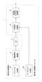
図1は、本発明の実施形態にかかる光コム測定装置1の構成を示す図である。本発明の実施形態にかかる光コム測定装置1は、複数種類の測定対象を有する被照射体を測定する。Figure 1 is a diagram showing the configuration of an optical frequency
例えば、被照射体は気体であり、ガスセル(本発明の実施形態におけるDUT2)に収容されている。より詳細には、ガスセルに気体が流入し、かつガスセルから気体が排出される。なお、気体は、複数種類(例えば、2種類)の測定対象を有する。また、光コム測定装置1は、測定対象の濃度を測定するようにしてもよい。測定対象の濃度の測定法は周知なので説明を省略する。For example, the object to be irradiated is a gas, which is contained in a gas cell (
本発明の実施形態にかかる光コム測定装置1は、シグナルコム生成部12a、ローカルコム生成部12b、複数帯域通過部14、干渉信号取得部16、周波数スペクトル測定部18を備える。The optical
シグナルコム生成部12aは、照射前シグナルコム(被照射体に照射される前のシグナルコム)を生成する。ローカルコム生成部12bは、ローカルコムを生成する。照射前シグナルコムおよびローカルコムは、光コムである。The signal
図2は、照射前シグナルコム(図2(a))およびローカルコム(図2(b))の周波数スペクトルである。縦軸は光パワーである。図2(a)を参照して、照射前シグナルコムの周波数スペクトルの周波数は、0、fs、2fs、…(繰り返し周波数fs)である。図2(b)を参照して、ローカルコムの周波数スペクトルの周波数は、0、fL、2fL、…(繰り返し周波数fL)である。ただし、ローカルコムは、照射前シグナルコムの繰り返し周波数fsを所定の差周波数Δf(=fs-fL)だけ異ならせたものである。なお、照射前シグナルコムおよびローカルコムの周波数は、おおむね光の周波数である。Figure 2 shows the frequency spectrum of the pre-irradiation signal comb (Figure 2(a)) and the local comb (Figure 2(b)). The vertical axis is optical power. Referring to Figure 2(a), the frequencies of the frequency spectrum of the pre-irradiation signal comb are 0, fs, 2fs, ... (repetition frequency fs). Referring to Figure 2(b), the frequencies of the frequency spectrum of the local comb are 0, fL, 2fL, ... (repetition frequency fL). However, the local comb differs from the repetition frequency fs of the pre-irradiation signal comb by a predetermined difference frequency Δf (=fs-fL). The frequencies of the pre-irradiation signal comb and the local comb are approximately the frequencies of light.
ただし、図2において、照射前シグナルコムおよびローカルコムの周波数スペクトルの周波数の最小値を(図示および説明の便宜上)0であるとして図示しているが、実際には、これらの最小値はmfs(=nfL)である(ただし、mおよびnは正の整数)。よって、実際には、照射前シグナルコムの周波数スペクトルの周波数は、mfs、mfs+fs、mfs+2fs、…であり、ローカルコムの周波数スペクトルの周波数は、nfL、nfL+fL、nfL+2fL、…である。なお、mは、例えば、およそ400万程度である。However, in FIG. 2, the minimum values of the frequencies of the frequency spectra of the pre-irradiation signal comb and the local comb are illustrated as 0 (for convenience of illustration and explanation), but in reality, these minimum values are mfs (=nfL) (where m and n are positive integers). Therefore, in reality, the frequencies of the frequency spectrum of the pre-irradiation signal comb are mfs, mfs+fs, mfs+2fs, ..., and the frequencies of the frequency spectrum of the local comb are nfL, nfL+fL, nfL+2fL, .... Note that m is, for example, approximately 4 million.
照射前シグナルコムを、DUT(ガスセル)2内の被照射体(気体)に照射すると、照射前シグナルコムがDUT2を透過して、照射後シグナルコムが得られる。照射後シグナルコムもまた、照射前シグナルコムと同じく、光コムである。なお、照射後シグナルコムは、複数帯域通過部14に与えられ、通過した成分が干渉信号取得部16に与えられる。When the pre-irradiation signal comb is irradiated onto the irradiated object (gas) inside the DUT (gas cell) 2, the pre-irradiation signal comb passes through the
図3は、照射後シグナルコム(複数帯域通過部14通過前)(図3(a))、照射後シグナルコム(複数帯域通過部14通過後)(図3(b))およびローカルコム(図3(c))の周波数スペクトルである。縦軸は光パワーである。ただし、図3(c)は、図2(b)と同じものである。Figure 3 shows the frequency spectrum of the post-irradiation signal comb (before passing through the multiple band pass section 14) (Figure 3(a)), the post-irradiation signal comb (after passing through the multiple band pass section 14) (Figure 3(b)), and the local comb (Figure 3(c)). The vertical axis is optical power. However, Figure 3(c) is the same as Figure 2(b).
なお、図3においても、図2と同様に、照射後シグナルコムおよびローカルコムの周波数スペクトルの周波数の最小値を(図示および説明の便宜上)0であるとして図示しているが、実際には、これらの最小値はmfs(=nfL)である。In Figure 3, as in Figure 2, the minimum frequency values of the frequency spectra of the post-irradiation signal comb and local comb are shown as 0 (for ease of illustration and explanation), but in reality, these minimum values are mfs (=nfL).
図3においては、DUT2内の被照射体に照射された光のパワーが、測定対象の各々に対応した所定の周波数(2fsおよび4fs)において、低くなる(光の吸収を意味する)ように変化するものとする。なお、図3においては、図示および説明の便宜上、被照射体に照射された光のパワーが低くなる周波数どうし(2fsおよび4fs)の差が2fsにしか過ぎないものとしているが、むしろこのような周波数どうしの差はもっと大きいことが一般的である(例えば図6を参照)。In FIG. 3, the power of the light irradiated to the irradiated object in DUT2 changes to become low (meaning light absorption) at predetermined frequencies (2 fs and 4 fs) corresponding to each of the measurement objects. Note that in FIG. 3, for the sake of convenience in illustration and explanation, the difference between the frequencies (2 fs and 4 fs) at which the power of the light irradiated to the irradiated object becomes low is only 2 fs, but in fact the difference between such frequencies is generally much larger (see FIG. 6, for example).
図3(a)を参照して、複数帯域通過部14通過前の照射後シグナルコムは、照射前シグナルコムのうち、測定対象の各々に対応した所定の周波数(2fsおよび4fs)において、光パワーが低い。Referring to FIG. 3(a), the post-irradiation signal comb before passing through the multiple
ここで、複数帯域通過部14が、周波数2fsおよび4fs近傍の帯域の信号を通過させ、他の帯域の信号を通過させないものとする。すると、図3(b)を参照して、複数帯域通過部14通過後の照射後シグナルコムは、周波数2fsおよび4fsの成分のみを有する。Here, it is assumed that the
干渉信号取得部16は、照射後シグナルコムとローカルコムとの干渉信号を取得する。所定の差周波数Δfは、比較的小さい値であるため、照射後シグナルコムとローカルコムとによってビートが発生する。干渉信号取得部16は、例えば、光カプラであり、照射後シグナルコムとローカルコムとが、偏波保持ファイバおよび光減衰器を介して、干渉信号取得部16に与えられる。周波数スペクトル測定部18は、干渉信号取得部16の取得結果の周波数スペクトルを測定する。The interference
図4は、周波数スペクトル測定部18による干渉信号の測定結果の周波数スペクトルである。図3(b)および図3(c)を参照して、照射後シグナルコムの周波数2fsの成分と、ローカルコムの周波数2fLの成分とがビートを生じ、両者の差の周波数2Δf(=2fs-2fL)の成分が測定される(図4参照)。しかも、照射後シグナルコムの周波数4fsの成分と、ローカルコムの周波数4fLの成分とがビートを生じ、両者の差の周波数4Δf(=4fs-4fL)の成分が測定される(図4参照)。Figure 4 shows the frequency spectrum of the interference signal measured by the frequency
照射後シグナルコムの周波数2fsおよび4fsの成分は高周波数過ぎて測定が困難であるが、干渉信号の周波数2Δfおよび4Δfの成分はマイクロ波程度の周波数なので、測定が可能となる。これにより、測定対象の各々の存在および濃度を測定することが可能となる。After irradiation, the 2fs and 4fs frequency components of the signal comb are too high to measure, but the 2Δf and 4Δf frequency components of the interference signal are microwave-like in frequency and therefore measurable. This makes it possible to measure the presence and concentration of each of the measurement targets.
なお、照射後シグナルコムの周波数fs、2fs、3fs…の成分が、干渉信号の周波数Δf、2Δf、3Δf…の成分に対応する。よって、干渉信号の周波数Δf、2Δf、3Δf…の成分を、周波数スペクトル測定部18によって測定すれば、照射後シグナルコムの周波数fs、2fs、3fs…の成分を測定できる。ただし、照射後シグナルコムを測定可能な帯域には制限がある。The frequency components of the post-irradiation signal comb, fs, 2fs, 3fs..., correspond to the frequency components of the interference signal, Δf, 2Δf, 3Δf.... Therefore, if the frequency components of the interference signal, Δf, 2Δf, 3Δf..., are measured by the frequency
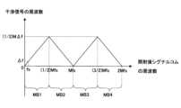
図5は、本発明の実施形態にかかる光コム測定装置1による照射後シグナルコムの周波数と干渉信号の周波数との対応関係を示す図である。ただし、図5には、測定可能帯域MB1、MB2、MB3、MB4が図示されている。また、図5におけるMは正の整数であり、Mfs=(M+1)fLである。なお、Mfs=(M+1)fLよりMΔf=fLとなる。ただし、図5において、照射後シグナルコムの周波数の最小値を(図示および説明の便宜上)0であるとして図示しているが、実際には、照射後シグナルコムの最小値はmfs(=nfL)である(図2と同様)。Figure 5 is a diagram showing the correspondence relationship between the frequency of the post-irradiation signal comb and the frequency of the interference signal by the optical
図11は、11fs=12fLである場合の、照射後シグナルコム(図11(a))およびローカルコム(図11(b))の周波数スペクトルである。すなわち、M=11である。よって、11Δf=fLとなる。ただし、図11(a)において、シグナルコムの吸収は図示省略している。Figure 11 shows the frequency spectrum of the post-irradiation signal comb (Figure 11(a)) and local comb (Figure 11(b)) when 11fs = 12fL. That is, M = 11. Therefore, 11Δf = fL. However, in Figure 11(a), the absorption of the signal comb is omitted.
図11を参照して、照射後シグナルコムの周波数fs、2fs、…、5fsの成分とローカルコムの周波数fL、2fL、…、5fLの成分とがビートを生じ、干渉信号の周波数Δf、2Δf、…、5Δfの成分となる。Referring to Figure 11, after irradiation, the components of the signal comb frequencies fs, 2fs, ..., 5fs and the components of the local comb frequencies fL, 2fL, ..., 5fL generate beats, resulting in interference signal components of frequencies Δf, 2Δf, ..., 5Δf.
しかし、照射後シグナルコムの周波数6fsの成分は、ローカルコムの周波数6fLの成分との周波数の差(6Δf)よりもローカルコムの周波数7fLの成分との周波数の差(5Δf)の方が小さい。よって、照射後シグナルコムの周波数6fsの成分とローカルコムの周波数7fLの成分とがビートを生じ、干渉信号の周波数5Δfの成分となる。同様に、照射後シグナルコムの周波数7fs、8fs、…、11fsの成分とローカルコムの周波数8fL、9fL、…、12fLの成分とがビートを生じ、干渉信号の周波数4Δf、3Δf、…0の成分となる。However, the frequency difference (5Δf) between the 6fs component of the post-irradiation signal comb and the 7fL component of the local comb is smaller than the frequency difference (6Δf) between the 6fL component of the local comb. Therefore, the 6fs component of the post-irradiation signal comb and the 7fL component of the local comb will generate a beat, resulting in a 5Δf component of the interference signal. Similarly, the 7fs, 8fs, ..., 11fs components of the post-irradiation signal comb and the 8fL, 9fL, ..., 12fL components of the local comb will generate a beat, resulting in a 4Δf, 3Δf, ..., 0 component of the interference signal.
ここで、測定可能帯域MB1を周波数0~(11/2)fs、測定可能帯域MB2を(11/2)fs~11fsとする。測定可能帯域MB1またはMB2以内の照射後シグナルコムについては、干渉信号の周波数に単一の照射後シグナルコムの周波数が対応している。Here, the measurable band MB1 is the frequency range from 0 to (11/2) fs, and the measurable band MB2 is the frequency range from (11/2) fs to 11 fs. For post-irradiation signal combs within the measurable band MB1 or MB2, the frequency of a single post-irradiation signal comb corresponds to the frequency of the interference signal.
一方、測定可能帯域MB1およびMB2においては、干渉信号の周波数に複数の照射後シグナルコムの周波数が対応してしまうことに留意されたい。例えば、干渉信号の周波数5Δfの成分は、照射後シグナルコムの周波数5fsおよび6fsの成分に対応する。これでは、干渉信号の周波数5Δfの成分を測定しても、照射後シグナルコムの周波数5fsおよび6fsの成分の和の光パワーしか取得できない(エイリアシングが生じる)。On the other hand, please note that in the measurable bands MB1 and MB2, the frequency of the interference signal corresponds to multiple frequencies of the post-irradiation signal comb. For example, the 5Δf frequency component of the interference signal corresponds to the 5fs and 6fs frequency components of the post-irradiation signal comb. In this case, even if the 5Δf frequency component of the interference signal is measured, only the optical power of the sum of the 5fs and 6fs frequency components of the post-irradiation signal comb can be obtained (aliasing occurs).
よって、測定可能帯域は、測定可能帯域MB1または測定可能帯域MB2ということになる。Therefore, the measurable band is either measurable band MB1 or measurable band MB2.
図5を参照して、測定可能帯域MB1(照射後シグナルコムの周波数0~(1/2)Mfs)においては、照射後シグナルコムの周波数がfs増加すると、干渉信号の周波数もΔf増加する。照射後シグナルコムの周波数が(1/2)Mfsのときに、干渉信号の周波数が最大値(1/2)MΔfをとる。Referring to Figure 5, in the measurable band MB1 (frequency of the
測定可能帯域MB2(照射後シグナルコムの周波数(1/2)Mfs~Mfs)においては、照射後シグナルコムの周波数がfs増加すると、干渉信号の周波数がΔf減少する。照射後シグナルコムの周波数がMfsのときに、干渉信号の周波数が最小値0をとる。In the measurable band MB2 (frequency of the post-irradiation signal comb, (1/2) Mfs to Mfs), when the frequency of the post-irradiation signal comb increases by fs, the frequency of the interference signal decreases by Δf. When the frequency of the post-irradiation signal comb is Mfs, the frequency of the interference signal is at its minimum value, 0.
測定可能帯域MB3(照射後シグナルコムの周波数Mfs~(3/2)Mfs)においては、照射後シグナルコムの周波数がfs増加すると、干渉信号の周波数もΔf増加する。照射後シグナルコムの周波数が(3/2)Mfsのときに、干渉信号の周波数が最大値(1/2)MΔfをとる。In the measurable band MB3 (frequency of the post-irradiation signal comb Mfs to (3/2)Mfs), when the frequency of the post-irradiation signal comb increases by fs, the frequency of the interference signal also increases by Δf. When the frequency of the post-irradiation signal comb is (3/2)Mfs, the frequency of the interference signal reaches a maximum value of (1/2)MΔf.
測定可能帯域MB4(照射後シグナルコムの周波数(3/2)Mfs~2Mfs)においては、照射後シグナルコムの周波数がfs増加すると、干渉信号の周波数がΔf減少する。照射後シグナルコムの周波数が2Mfsのときに、干渉信号の周波数が最小値0をとる。In the measurable band MB4 (frequency of the post-irradiation signal comb from (3/2)Mfs to 2Mfs), when the frequency of the post-irradiation signal comb increases by fs, the frequency of the interference signal decreases by Δf. When the frequency of the post-irradiation signal comb is 2Mfs, the frequency of the interference signal reaches its minimum value of 0.
なお、測定可能帯域MB1、MB2、MB3、MB4の帯域幅は、(1/2)Mfsである。The bandwidth of the measurable bands MB1, MB2, MB3, and MB4 is (1/2)Mfs.
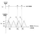
図6は、被照射体内の測定対象の吸収スペクトル(図6(a))、照射後シグナルコムの周波数と干渉信号の周波数との対応関係(比較例)(図6(b))、照射後シグナルコムの周波数と干渉信号の周波数との対応関係(実施形態)(図6(c))を示す図である。Figure 6 shows the absorption spectrum of the measurement target in the irradiated body (Figure 6(a)), the correspondence between the frequency of the signal comb after irradiation and the frequency of the interference signal (comparative example) (Figure 6(b)), and the correspondence between the frequency of the signal comb after irradiation and the frequency of the interference signal (embodiment) (Figure 6(c)).
図6(a)を参照して、被照射体に照射された光のパワーが、測定対象の各々に対応した所定の周波数S1、S2において変化する。具体的には、所定の周波数S1、S2において光が吸収されるので、透過率が低くなる。なお、周波数S1と周波数S2との差は、およそ23THz程度と大きな値である。Referring to FIG. 6(a), the power of the light irradiated to the irradiated object changes at the predetermined frequencies S1 and S2 corresponding to each of the measurement objects. Specifically, light is absorbed at the predetermined frequencies S1 and S2, so the transmittance decreases. The difference between the frequencies S1 and S2 is a large value of approximately 23 THz.
図6(b)を参照して、測定可能帯域MB2内の周波数の照射後シグナルコムを用いて干渉信号を得て測定を行うものとする(比較例)。すると、測定可能帯域MB2内に、周波数S1と周波数S2とを含む必要があるので、測定可能帯域MB2の帯域幅が広くなってしまう。ここで、(測定可能帯域MB2の帯域)=(1/2)Mfsであるところ、測定可能帯域MB2の帯域幅を広くするためには、Mを大きくする必要がある。しかも、MΔf=fLであるため、Mを大きくするとΔfは小さくなってしまう。測定一回にかかる時間はΔfの逆数であるが、測定は何回も(例えば、1000回)繰り返し行うので、Δfが小さいと測定にかかる時間は長くなってしまう。Referring to FIG. 6(b), after irradiation with a frequency within the measurable band MB2, an interference signal is obtained using a signal comb and measurement is performed (comparative example). In this case, since it is necessary to include frequencies S1 and S2 within the measurable band MB2, the bandwidth of the measurable band MB2 becomes wider. Here, (bandwidth of measurable band MB2) = (1/2) Mfs, and in order to widen the bandwidth of the measurable band MB2, it is necessary to increase M. Furthermore, since MΔf = fL, increasing M reduces Δf. The time required for one measurement is the reciprocal of Δf, but since the measurement is repeated many times (for example, 1000 times), the time required for measurement becomes longer when Δf is small.
そこで、本発明の実施形態においては、図6(c)に示すように、測定可能帯域のうち複数のものMBx、MByが、所定の周波数S1、S2を一つ以上含む。例えば、図6(c)に示すように、測定可能帯域のうちの一つずつが、所定の周波数のうちの一つずつを含む(測定可能帯域MBxが所定の周波数S1を、測定可能帯域MByが所定の周波数S2を含む)。測定可能帯域の一つ(MB2)が、所定の周波数全て(S1、S2)を含む比較例(図6(b)参照)と比べると、測定可能帯域のうち複数のものMBx、MByが、所定の周波数S1、S2を一つ以上含む本発明の実施形態(図6(c)参照)は、測定可能帯域MBx、MByの帯域幅を狭くすることができる。ただし、図6(c)において、照射後シグナルコムの周波数の最小値を(図示および説明の便宜上)0であるとして図示しているが、実際には、照射後シグナルコムの周波数の最小値はmfs(=nfL)である(図2と同様)。In the embodiment of the present invention, as shown in FIG. 6(c), the measurable bands MBx, MBy each include one or more of the predetermined frequencies S1, S2. For example, as shown in FIG. 6(c), each of the measurable bands includes one of the predetermined frequencies (the measurable band MBx includes the predetermined frequency S1, and the measurable band MBy includes the predetermined frequency S2). Compared to the comparative example (see FIG. 6(b)) in which one of the measurable bands (MB2) includes all of the predetermined frequencies (S1, S2), the embodiment of the present invention (see FIG. 6(c)) in which the measurable bands MBx, MBy each include one or more of the predetermined frequencies S1, S2 can narrow the bandwidth of the measurable bands MBx, MBy. However, in FIG. 6(c), the minimum frequency of the post-irradiation signal comb is illustrated as 0 (for convenience of illustration and explanation), but in reality, the minimum frequency of the post-irradiation signal comb is mfs (=nfL) (similar to FIG. 2).
測定可能帯域MBx、MBy(図6(c)参照)の帯域幅は、測定可能帯域MB2(図6(b)参照)よりも狭い。このため、Mを大きくする必要が無い。しかも、MΔf=fLであるため、Mを大きくしなくてすめばΔfも小さくならない。測定一回にかかる時間はΔfの逆数であり、測定は何回も(例えば、1000回)繰り返し行うにせよ、Δfが小さくならなければ測定にかかる時間を短くすることができる。The bandwidth of measurable bands MBx, MBy (see FIG. 6(c)) is narrower than measurable band MB2 (see FIG. 6(b)). For this reason, there is no need to increase M. Furthermore, since MΔf=fL, if M does not need to be increased, Δf will not become small. The time required for one measurement is the reciprocal of Δf, and even if the measurement is repeated many times (for example, 1000 times), the time required for measurement can be shortened as long as Δf does not become small.
しかし、測定可能帯域MBxおよびMBy内の周波数の照射後シグナルコムを用いて干渉信号を得て測定を行えば、エイリアシングが生じる。However, if measurements are made using a signal comb to obtain interference signals after irradiation with frequencies within the measurable bands MBx and MBy, aliasing will occur.
そこで、照射後シグナルコムの測定可能帯域MBx内の必要帯域P1内の成分に対応する干渉信号(周波数帯域B1)および照射後シグナルコム測定可能帯域MBy内の必要帯域P2内の成分に対応する干渉信号(周波数帯域B2)を得て測定を行うようにする。このような測定を行うためには、照射後シグナルコムが、複数の必要帯域P1およびP2内の成分のみを有しているようにすればよい。例えば、複数帯域通過部14が、照射後シグナルコムを受け、複数の必要帯域P1およびP2の成分を通過させて、干渉信号取得部16に与えるようにすればよい。Therefore, measurements are performed by obtaining an interference signal (frequency band B1) corresponding to components in the necessary band P1 in the measurable band MBx of the post-irradiation signal comb and an interference signal (frequency band B2) corresponding to components in the necessary band P2 in the measurable band MBy of the post-irradiation signal comb. To perform such measurements, the post-irradiation signal comb only needs to have components in the multiple necessary bands P1 and P2. For example, the multiple
ただし、複数の必要帯域P1およびP2が、全ての所定の周波数S1およびS2を含む。しかも、複数の必要帯域P1およびP2の各々に対応する干渉信号の周波数帯域B1およびB2が互いに重複した領域を有しない。However, the multiple necessary bands P1 and P2 include all of the predetermined frequencies S1 and S2. Moreover, the frequency bands B1 and B2 of the interference signal corresponding to each of the multiple necessary bands P1 and P2 do not have overlapping areas with each other.
干渉信号の周波数帯域B1およびB2が互いに重複しないため、干渉信号の周波数帯域B1内の成分が得られれば、照射後シグナルコムの測定可能帯域MBx内の成分であることが分かる。さらに、干渉信号の周波数帯域B2内の成分が得られれば、照射後シグナルコムの測定可能帯域MBy内の成分であることが分かる。照射後シグナルコムの測定可能帯域MBxおよびMByの内の成分が混合されて検出されない(エイリアシングが生じない)ことに留意されたい。Since the frequency bands B1 and B2 of the interference signal do not overlap with each other, if a component in frequency band B1 of the interference signal is obtained, it is known that the component is in the measurable band MBx of the post-irradiation signal comb. Furthermore, if a component in frequency band B2 of the interference signal is obtained, it is known that the component is in the measurable band MBy of the post-irradiation signal comb. Note that the components in the measurable bands MBx and MBy of the post-irradiation signal comb are mixed and not detected (no aliasing occurs).
次に、本発明の実施形態の動作を説明する。Next, we will explain the operation of an embodiment of the present invention.
照射前シグナルコム(図2(a)参照)が、シグナルコム生成部12aからDUT(ガスセル)2内の被照射体(気体)に照射されると、照射前シグナルコムがDUT2を透過して、照射後シグナルコムが得られる。When the pre-irradiation signal comb (see FIG. 2(a)) is irradiated from the signal
照射後シグナルコムは、複数帯域通過部14に与えられ、通過した成分が干渉信号取得部16に与えられる。ただし、複数帯域通過部14の通過帯域は、必要帯域P1およびP2である(図6(c)参照)。After irradiation, the signal comb is sent to the
また、ローカルコム(図2(b)参照)が、ローカルコム生成部12bから干渉信号取得部16に与えられる。In addition, the local comb (see FIG. 2(b)) is provided from the local
照射後シグナルコム(複数帯域通過部14を通過した成分)とローカルコムとの干渉信号が、干渉信号取得部16により取得される。干渉信号取得部16の取得結果の周波数スペクトルが、周波数スペクトル測定部18により測定される。The interference signal between the post-irradiation signal comb (components that have passed through the multiple band pass unit 14) and the local comb is acquired by the interference
本発明の実施形態によれば、デュアルコム分光法によって複数種類の測定対象を測定するためにかかる時間を短くすることができる。According to an embodiment of the present invention, the time required to measure multiple types of objects using dual comb spectroscopy can be reduced.
すなわち、測定可能帯域の一つ(MB2)が、所定の周波数全て(S1、S2)を含む比較例(図6(b)参照)と比べると、測定可能帯域MBxが所定の周波数S1を、測定可能帯域MByが所定の周波数S2を含む本発明の実施形態(図6(c)参照)によれば、測定可能帯域MBx、MByの帯域幅を狭くすることができる。このため、Mを大きくする必要が無い。しかも、MΔf=fLであるため、Mを大きくしなくてすめばΔfも小さくならない。測定一回にかかる時間はΔfの逆数であり、測定は何回も(例えば、1000回)繰り返し行うにせよ、Δfが小さくならなければ測定にかかる時間を短くすることができる。That is, compared to a comparative example (see FIG. 6(b)) in which one of the measurable bands (MB2) includes all of the predetermined frequencies (S1, S2), according to an embodiment of the present invention (see FIG. 6(c)) in which the measurable band MBx includes the predetermined frequency S1 and the measurable band MBy includes the predetermined frequency S2, the bandwidth of the measurable bands MBx and MBy can be narrowed. For this reason, there is no need to increase M. Furthermore, since MΔf=fL, if M does not need to be increased, Δf will not become small. The time required for one measurement is the reciprocal of Δf, and even if the measurement is repeated many times (for example, 1000 times), the time required for the measurement can be shortened as long as Δf does not become small.
しかも、複数帯域通過部14が、照射後シグナルコムを受け、複数の必要帯域P1およびP2の成分を通過させて、干渉信号取得部16に与えるようにしたので、干渉信号の周波数帯域B1およびB2が互いに重複した領域を有しない。よって、複数の測定可能帯域MBxおよびMbyに基づく干渉信号を測定したにも関わらず、エイリアシングが生じない。Moreover, the multiple
なお、本発明の実施形態には色々な変形例が考えられる。There are many possible variations to the embodiments of the present invention.
<変形例1>
図7は、本発明の実施形態の変形例1にかかる光コム測定装置1の構成を示す図である。変形例1にかかる光コム測定装置1においては、複数帯域通過部14を、DUT2と干渉信号取得部16との間にかえて、ローカルコム生成部12bと干渉信号取得部16との間に配置する。 <
7 is a diagram showing a configuration of the optical
複数帯域通過部14は、ローカルコム生成部12bからローカルコムを受け、複数の必要帯域P1およびP2の成分を通過させて、干渉信号取得部16に与える。この場合、ローカルコムが、複数の必要帯域P1およびP2内の成分のみを有する。他は、本発明の実施形態と同様であり説明を省略する。The
<変形例2>
図8は、本発明の実施形態の変形例2にかかる光コム測定装置1の構成を示す図である。変形例2にかかる光コム測定装置1においては、複数帯域通過部を、DUT2と干渉信号取得部16との間(複数帯域通過部14a)にも、ローカルコム生成部12bと干渉信号取得部16との間(複数帯域通過部14b)にも配置する。 <
8 is a diagram showing a configuration of the optical
複数帯域通過部14aは、本発明の実施形態の複数帯域通過部14(図1参照)と同様である。複数帯域通過部14bは、本発明の実施形態の変形例1の複数帯域通過部14(図7参照)と同様である。この場合、照射後シグナルコムおよびローカルコムが、複数の必要帯域P1およびP2内の成分のみを有する。他は、本発明の実施形態と同様であり説明を省略する。The
<変形例3>
図9は、本発明の実施形態の変形例3にかかる光コム測定装置1の構成を示す図である。変形例3にかかる光コム測定装置1においては、複数帯域通過部14を、DUT2と干渉信号取得部16との間にかえて、シグナルコム生成部12aとDUT2との間に配置する。 <Modification 3>
9 is a diagram showing a configuration of the optical
複数帯域通過部14は、シグナルコム生成部12aからシグナルコムを受け、複数の必要帯域P1およびP2の成分を通過させて、DUT2に与える。他は、本発明の実施形態と同様であり説明を省略する。The
<変形例4>
図10は、本発明の実施形態の変形例4にかかる光コム測定装置1の構成を示す図である。変形例4にかかる光コム測定装置1においては、複数帯域通過部を、シグナルコム生成部12aとDUT2との間の間(複数帯域通過部14a)にも、ローカルコム生成部12bと干渉信号取得部16との間(複数帯域通過部14b)にも配置する。 <Modification 4>
10 is a diagram showing a configuration of the optical
複数帯域通過部14aは、本発明の実施形態の変形例3の複数帯域通過部14(図9参照)と同様である。複数帯域通過部14bは、本発明の実施形態の変形例1の複数帯域通過部14(図7参照)と同様である。他は、本発明の実施形態と同様であり説明を省略する。The
<変形例5>
本発明の実施形態の変形例5は、本発明の実施形態の光コム測定装置1から複数帯域通過部14を除去したものである。ただし、照射前シグナルコムおよびローカルコムのいずれか一方または双方が、全ての所定の周波数S1、S2を含む複数の必要帯域P1およびP2内の成分のみを有する。 <Modification 5>
In the fifth modified example of the present embodiment, the multiple
<変形例6>
図12は、本発明の実施形態の変形例6にかかる被照射体内の測定対象の吸収スペクトル(図12(a))、照射後シグナルコムの周波数と干渉信号の周波数との対応関係(実施形態)(図12(b))を示す図である。ただし、図12(b)において、照射後シグナルコムの周波数の最小値を(図示および説明の便宜上)0であるとして図示しているが、実際には、照射後シグナルコムの周波数の最小値はmfs(=nfL)である(図2と同様)。 <Modification 6>
12A and 12B are diagrams showing the absorption spectrum of a measurement target in an irradiated body according to a sixth embodiment of the present invention (FIG. 12A), and the correspondence between the frequency of the post-irradiation signal comb and the frequency of the interference signal (embodiment) (FIG. 12B). Note that in FIG. 12B, the minimum frequency of the post-irradiation signal comb is shown as 0 (for convenience of illustration and explanation), but in reality, the minimum frequency of the post-irradiation signal comb is mfs (=nfL) (similar to FIG. 2).
変形例6は、図12(a)を参照して、本発明の実施形態(測定対象に対応した所定の周波数がS1、S2の2種類)にかえて、測定対象に対応した所定の周波数S1、S2、S3が3種類あるものである。ただし、図12(b)を参照して、測定可能帯域のうちの一つずつが、所定の周波数のうちの一つずつを含む。すなわち、測定可能帯域MBxおよび必要帯域P1が所定の周波数S1を、測定可能帯域MByおよび必要帯域P2が所定の周波数S2を、測定可能帯域MBzおよび必要帯域P3が所定の周波数S3を含む。しかも、複数の必要帯域P1、P2およびP3の各々に対応する干渉信号の周波数帯域B1、B2およびB3が互いに重複した領域を有しない。Referring to FIG. 12(a), in the sixth modification, instead of the embodiment of the present invention (where the predetermined frequencies corresponding to the measurement object are two, S1 and S2), there are three predetermined frequencies corresponding to the measurement object, S1, S2, and S3. However, referring to FIG. 12(b), each of the measurable bands includes each of the predetermined frequencies. That is, the measurable band MBx and the necessary band P1 include the predetermined frequency S1, the measurable band MBy and the necessary band P2 include the predetermined frequency S2, and the measurable band MBz and the necessary band P3 include the predetermined frequency S3. Moreover, the frequency bands B1, B2, and B3 of the interference signal corresponding to each of the multiple necessary bands P1, P2, and P3 do not have overlapping regions with each other.
<変形例7>
図13は、本発明の実施形態の変形例7にかかる被照射体内の測定対象の吸収スペクトル(図13(a))、照射後シグナルコムの周波数と干渉信号の周波数との対応関係(実施形態)(図13(b))を示す図である。ただし、図13(b)において、照射後シグナルコムの周波数の最小値を(図示および説明の便宜上)0であるとして図示しているが、実際には、照射後シグナルコムの周波数の最小値はmfs(=nfL)である(図2と同様)。 <Modification 7>
13A and 13B are diagrams showing the absorption spectrum of a measurement target in an irradiated body according to a seventh modified embodiment of the present invention (FIG. 13A), and the correspondence between the frequency of the post-irradiation signal comb and the frequency of the interference signal (embodiment) (FIG. 13B). Note that in FIG. 13B, the minimum frequency of the post-irradiation signal comb is shown as 0 (for convenience of illustration and explanation), but in reality, the minimum frequency of the post-irradiation signal comb is mfs (=nfL) (similar to FIG. 2).
変形例7は、図13(a)を参照して、測定対象に対応した所定の周波数S1、S2、S3が3種類あるものである。ただし、所定の周波数S2およびS3が近接している。そこで、図13(b)を参照して、測定可能帯域のうちのいずれか一つ以上(例えば、MBy)が、複数の所定の周波数(例えば、S2およびS3)を含む。すなわち、測定可能帯域MBxおよび必要帯域P1が所定の周波数S1を、測定可能帯域MByおよび必要帯域P2が所定の周波数S2および所定の周波数S3を含む。しかも、複数の必要帯域P1およびP2の各々に対応する干渉信号の周波数帯域B1およびB2が互いに重複した領域を有しない。Referring to FIG. 13(a), variant 7 has three predetermined frequencies S1, S2, and S3 corresponding to the measurement target. However, the predetermined frequencies S2 and S3 are close to each other. Therefore, referring to FIG. 13(b), one or more of the measurable bands (e.g., MBy) includes multiple predetermined frequencies (e.g., S2 and S3). That is, the measurable band MBx and the necessary band P1 include the predetermined frequency S1, and the measurable band MBy and the necessary band P2 include the predetermined frequency S2 and the predetermined frequency S3. Moreover, the frequency bands B1 and B2 of the interference signal corresponding to each of the multiple necessary bands P1 and P2 do not have overlapping areas with each other.
<変形例8>
本発明の実施形態の変形例8は、被照射体が液体または固体であるものである。例えば、測定対象の有無を測定する。例えば、被照射体が固体の場合の一例としては、FTIRを用いて、光ファイバのOH基の吸収(1.4um帯)の測定を行う。被照射体が液体の場合の一例としては、FTIRを用いて、水が含有されるかなどをOH基の吸収の有無で判断する。 <Modification 8>
In the eighth modified embodiment of the present invention, the irradiated object is a liquid or a solid. For example, the presence or absence of a measurement target is measured. For example, when the irradiated object is a solid, FTIR is used to measure the absorption of OH groups in an optical fiber (1.4 um band). When the irradiated object is a liquid, FTIR is used to determine whether water is contained or not based on the presence or absence of OH group absorption.
<変形例9>
本発明の実施形態の変形例9は、干渉信号取得部14がパワービームスプリッタであるものである。複数帯域通過部14、14a、14bの配置または不使用は、本発明の実施形態、変形例1、変形例2、変形例3、変形例4および変形例5と同様である。 <Modification 9>
In a ninth modification of the embodiment of the present invention, the interference
なお、シグナルコム生成部12aおよびローカルコム生成部12bの出力は、1/2波長板および1/4波長板を通過させてもよい。干渉信号取得部14の出力は、光減衰器および1/2波長板を通過させてもよい。The outputs of the signal
1 光コム測定装置
2 DUT(ガスセル)
12a シグナルコム生成部
12b ローカルコム生成部
14、14a、14b 複数帯域通過部
16 干渉信号取得部
18 周波数スペクトル測定部
MB1、MB2、MB3、MB4、MBx、MBy、MBz 測定可能帯域
fs シグナルコムの周波数の繰り返し周波数
fL ローカルコムの周波数の繰り返し周波数
Δf ローカルコムとシグナルコムの繰り返し周波数の差
B1、B2、B3 周波数帯域
P1、P2、P3 必要帯域
S1、S2、S3 所定の周波数 1 Optical
12a
Claims (14)
Translated fromJapanese照射前シグナルコムを前記被照射体に照射して得られた照射後シグナルコムと、前記照射前シグナルコムの繰り返し周波数を所定の差周波数だけ異ならせたローカルコムとの干渉信号を取得する干渉信号取得部と、
前記干渉信号取得部の取得結果の周波数スペクトルを測定する周波数スペクトル測定部と、
を備え、
前記照射前シグナルコム、前記照射後シグナルコムおよび前記ローカルコムが光コムであり、
前記被照射体に照射された光のパワーが、前記測定対象の各々に対応した所定の周波数において変化し、
前記干渉信号の周波数に単一の前記照射後シグナルコムの周波数が対応する前記照射後シグナルコムの周波数領域である測定可能帯域のうち複数のものが、前記所定の周波数を一つ以上含み、
前記干渉信号取得部に与えられる前記照射後シグナルコムおよび前記ローカルコムのいずれか一方または双方が、全ての前記所定の周波数を含む複数の必要帯域内の成分のみを有し、
前記複数の必要帯域の各々に対応する前記干渉信号の周波数帯域が互いに重複した領域を有しない、
光コム測定装置。 An optical comb measurement device for measuring an irradiated object having a plurality of types of measurement targets,
an interference signal acquisition unit that acquires an interference signal between a post-irradiation signal comb obtained by irradiating the irradiated object with a pre-irradiation signal comb and a local comb in which the repetition frequency of the pre-irradiation signal comb is changed by a predetermined difference frequency;
a frequency spectrum measurement unit for measuring a frequency spectrum of the result of acquisition by the interference signal acquisition unit;
Equipped with
the pre-irradiation signal comb, the post-irradiation signal comb, and the local comb are optical combs;
The power of the light irradiated to the irradiated object is changed at a predetermined frequency corresponding to each of the measurement objects,
A plurality of measurable bands, which are frequency ranges of the post-irradiation signal comb in which the frequency of the single post-irradiation signal comb corresponds to the frequency of the interference signal, include one or more of the predetermined frequencies;
one or both of the post-irradiation signal comb and the local comb provided to the interference signal acquisition unit have only components within a plurality of required bands including all of the predetermined frequencies;
The frequency bands of the interference signals corresponding to the plurality of necessary bands do not have overlapping regions with each other.
Optical comb measurement device.
前記照射前シグナルコムおよび前記ローカルコムのいずれか一方または双方を受け、複数の前記必要帯域の成分を通過させる複数帯域通過部を備えた光コム測定装置。 2. The optical frequency comb measurement device according to claim 1,
An optical comb measurement device including a multiple band pass section that receives either one or both of the pre-irradiation signal comb and the local comb and passes multiple components of the required bands.
前記照射後シグナルコムおよび前記ローカルコムのいずれか一方または双方を受け、複数の前記必要帯域の成分を通過させる複数帯域通過部を備えた光コム測定装置。 2. The optical frequency comb measurement device according to claim 1,
An optical comb measurement device including a multiple band pass section that receives either one or both of the post-irradiation signal comb and the local comb and passes multiple components of the required bands.
前記照射前シグナルコムおよび前記ローカルコムのいずれか一方または双方が、全ての前記所定の周波数を含む複数の必要帯域内の成分のみを有する光コム測定装置。 2. The optical frequency comb measurement device according to claim 1,
An optical comb measurement device in which either one or both of the pre-irradiation signal comb and the local comb have only components within a plurality of required bands that include all of the predetermined frequencies.
前記測定可能帯域のうちの一つずつが、前記所定の周波数のうちの一つずつを含む光コム測定装置。 2. The optical frequency comb measurement device according to claim 1,
An optical comb measurement device, wherein each of the measurable bands includes each of the predetermined frequencies.
前記測定可能帯域のうちのいずれか一つ以上が、複数の前記所定の周波数を含む光コム測定装置。 2. The optical frequency comb measurement device according to claim 1,
An optical comb measurement device, wherein at least one of the measurable bands includes a plurality of the predetermined frequencies.
前記被照射体が気体である光コム測定装置。 2. The optical frequency comb measurement device according to claim 1,
The optical comb measurement device, wherein the irradiated object is a gas.
前記被照射体がガスセルに収容されている光コム測定装置。 The optical frequency comb measurement device according to claim 7,
The optical comb measurement device, in which the irradiated object is accommodated in a gas cell.
前記測定対象の濃度を測定する光コム測定装置。 The optical frequency comb measurement device according to claim 7,
An optical comb measurement device that measures the concentration of the measurement object.
前記被照射体が液体または固体である光コム測定装置。 2. The optical frequency comb measurement device according to claim 1,
The optical comb measurement device, wherein the irradiated object is a liquid or a solid.
前記測定対象の有無を測定する光コム測定装置。 The optical frequency comb measurement device according to claim 10,
An optical comb measurement device that measures the presence or absence of the measurement target.
前記照射後シグナルコムおよび前記ローカルコムが、偏波保持ファイバを介して、前記干渉信号取得部に与えられる光コム測定装置。 2. The optical frequency comb measurement device according to claim 1,
The optical comb measurement device provides the post-irradiation signal comb and the local comb to the interference signal acquisition unit via a polarization maintaining fiber.
前記干渉信号取得部が光カプラである光コム測定装置。 2. The optical frequency comb measurement device according to claim 1,
The optical comb measurement device, wherein the interference signal acquisition unit is an optical coupler.
前記干渉信号取得部がパワービームスプリッタである光コム測定装置。 2. The optical frequency comb measurement device according to claim 1,
The optical comb measurement device, wherein the interference signal acquisition unit is a power beam splitter.
Priority Applications (3)
| Application Number | Priority Date | Filing Date | Title |
|---|---|---|---|
| JP2023013766AJP2024109153A (en) | 2023-02-01 | 2023-02-01 | Optical comb measurement device |
| US18/387,966US20240255423A1 (en) | 2023-02-01 | 2023-11-08 | Optical comb measuring apparatus |
| DE102023134177.4ADE102023134177A1 (en) | 2023-02-01 | 2023-12-06 | OPTICAL COMB MEASURING DEVICE |
Applications Claiming Priority (1)
| Application Number | Priority Date | Filing Date | Title |
|---|---|---|---|
| JP2023013766AJP2024109153A (en) | 2023-02-01 | 2023-02-01 | Optical comb measurement device |
Publications (1)
| Publication Number | Publication Date |
|---|---|
| JP2024109153Atrue JP2024109153A (en) | 2024-08-14 |
Family
ID=91852852
Family Applications (1)
| Application Number | Title | Priority Date | Filing Date |
|---|---|---|---|
| JP2023013766APendingJP2024109153A (en) | 2023-02-01 | 2023-02-01 | Optical comb measurement device |
Country Status (3)
| Country | Link |
|---|---|
| US (1) | US20240255423A1 (en) |
| JP (1) | JP2024109153A (en) |
| DE (1) | DE102023134177A1 (en) |
Family Cites Families (11)
| Publication number | Priority date | Publication date | Assignee | Title |
|---|---|---|---|---|
| US8564785B2 (en)* | 2009-09-18 | 2013-10-22 | The United States of America, as represented by the Secretary of Commerce, The National Institute of Standards and Technology | Comb-based spectroscopy with synchronous sampling for real-time averaging |
| US8693004B2 (en)* | 2010-07-02 | 2014-04-08 | Sandia Corporation | Dual-etalon cavity ring-down frequency-comb spectroscopy with broad band light source |
| WO2015045266A1 (en) | 2013-09-24 | 2015-04-02 | 国立大学法人東京農工大学 | Measurement device |
| JP2015132774A (en) | 2014-01-15 | 2015-07-23 | 日本電信電話株式会社 | wavelength conversion light source |
| WO2018102915A1 (en)* | 2016-12-07 | 2018-06-14 | UNIVERSITé LAVAL | Methods for performing dual-comb interferometry |
| EP3537121A1 (en) | 2018-03-09 | 2019-09-11 | Crystalline Mirror Solutions GmbH | Dual-comb generation from a single laser cavity via spectral subdivision |
| WO2021019918A1 (en)* | 2019-07-31 | 2021-02-04 | パナソニックIpマネジメント株式会社 | Dual optical frequency comb light-emitting device |
| GB2586597B (en)* | 2019-08-26 | 2021-09-01 | Irsweep Ag | Dual-comb spectroscopy |
| US11112310B2 (en)* | 2019-08-29 | 2021-09-07 | Dublin City University | Dual-comb spectroscopy |
| US11841271B2 (en)* | 2020-11-23 | 2023-12-12 | California Institute Of Technology | Cross-comb spectroscopy |
| US12276548B2 (en)* | 2022-04-29 | 2025-04-15 | Government Of The United States Of America, As Represented By The Secretary Of Commerce | Apparatus and method for dual comb spectroscopy |
- 2023
- 2023-02-01JPJP2023013766Apatent/JP2024109153A/enactivePending
- 2023-11-08USUS18/387,966patent/US20240255423A1/enactivePending
- 2023-12-06DEDE102023134177.4Apatent/DE102023134177A1/enactivePending
Also Published As
| Publication number | Publication date |
|---|---|
| US20240255423A1 (en) | 2024-08-01 |
| DE102023134177A1 (en) | 2024-08-01 |
Similar Documents
| Publication | Publication Date | Title |
|---|---|---|
| Kaneyasu et al. | Electron wave packet interference in atomic inner-shell excitation | |
| Davis et al. | Experimental single-photon pulse characterization by electro-optic shearing interferometry | |
| De Zela | Role of weak values in strong measurements | |
| Lam et al. | Alignment dependence of photoelectron angular distributions in the few-photon ionization of molecules by ultraviolet pulses | |
| JPWO2020202547A1 (en) | Light distance measuring device | |
| Herd et al. | Absolute frequency measurement of the 6 D 5/2 level of neutral Cs 133 using two-photon spectroscopy | |
| JP2024109153A (en) | Optical comb measurement device | |
| JP5475341B2 (en) | Multi-wavelength simultaneous absorption spectroscopy apparatus and multi-wavelength simultaneous absorption spectroscopy method | |
| Kube | Review of synchrotron radiation based diagnostics for transverse profile measurements | |
| Loriot et al. | Resolving XUV induced femtosecond and attosecond dynamics in polyatomic molecules with a compact attosecond beamline | |
| Lock et al. | Measuring the intensity and phase of high-order harmonic emission from aligned molecules | |
| JP2004340926A (en) | Apparatus and method for determining chromatic dispersion of optical component | |
| Stalnaker et al. | Measurement of the 4 S 1/2→ 6 S 1/2 transition frequency in atomic potassium via direct frequency-comb spectroscopy | |
| Ohshima et al. | Rotational wave-packet imaging spectroscopy of the ethylene dimer | |
| CN104316185A (en) | Method and device for monitoring laser spectrum and spectral energy distribution simultaneously | |
| CN114674486A (en) | A fast vacuum partial pressure measuring device and method | |
| Okubo et al. | The pressure effect on the line profiles observed in the ν1+ ν3 band of acetylene: Revisited | |
| Kuznetsov et al. | Interferometric studies of the electron density dynamics at the periphery of a micropinch discharge | |
| Le Bouquin et al. | Post-processing the VLTI fringe-tracking data: first measurements of stars | |
| Zhang et al. | Design and analysis of a dual-grating spatial heterodyne spectrometer system | |
| Niay et al. | An analysis of the D1Πu-X1Σg+ bands of Na2 through absorption and polarization labeling spectroscopy | |
| Zhao et al. | Line profile analysis of an astronomical spectrograph with a laser frequency comb | |
| Zagorulko et al. | Frequency and Intensity Noise Measurement of Single-Frequency Lasers | |
| Bhatia et al. | Characterizing the Single mode-Multimode-Multimode (SMm) device for exciting a single radial mode in a multimode fiber | |
| Chen et al. | Feed-forward coherent dual-comb spectroscopy |
Legal Events
| Date | Code | Title | Description |
|---|---|---|---|
| A521 | Request for written amendment filed | Free format text:JAPANESE INTERMEDIATE CODE: A523 Effective date:20230201 |