JP2024101879A - Information processing device - Google Patents
Information processing deviceDownload PDFInfo
- Publication number
- JP2024101879A JP2024101879AJP2023006061AJP2023006061AJP2024101879AJP 2024101879 AJP2024101879 AJP 2024101879AJP 2023006061 AJP2023006061 AJP 2023006061AJP 2023006061 AJP2023006061 AJP 2023006061AJP 2024101879 AJP2024101879 AJP 2024101879A
- Authority
- JP
- Japan
- Prior art keywords
- information processing
- processing device
- light field
- control unit
- field display
- Prior art date
- Legal status (The legal status is an assumption and is not a legal conclusion. Google has not performed a legal analysis and makes no representation as to the accuracy of the status listed.)
- Pending
Links
Images


Landscapes
- Testing, Inspecting, Measuring Of Stereoscopic Televisions And Televisions (AREA)
- User Interface Of Digital Computer (AREA)
Abstract
Translated fromJapanese
Description
Translated fromJapanese本開示は、情報処理装置に関する。This disclosure relates to an information processing device.
従来、三次元画像をユーザに提示するために、ユーザの視線方向から注視点位置(衝突点)を検出し、注視点位置と提示画像の距離情報とに基づいて、注視点の距離(衝突点の深さ)にある物体について焦点を合わせた画像を生成し、注視点の距離と異なる距離にあるその他の物体については注視点の距離からの距離差に応じた焦点ぼけ処理を施した画像を提示する技術が知られている(例えば特許文献1)。Conventionally, in order to present a three-dimensional image to a user, a technology is known in which the position of the gaze point (collision point) is detected from the direction of the user's line of sight, and an image is generated in which an object at the distance of the gaze point (depth of the collision point) is focused based on the gaze point position and distance information of the presented image, and for other objects at distances different from the gaze point, an image is presented in which defocusing processing has been applied according to the difference in distance from the gaze point (for example, Patent Document 1).
上記従来技術は、Z軸方向の距離も使用して焦点を設定している。しかしZ軸方向の距離を使用しない場合、対象焦点がディスプレイ上に設定される。このため、ピントが合わない範囲が存在する。特に、焦点を合わせた深さからのずれが大きいときにぼやけが存在する。The above conventional technology also uses the distance in the Z-axis direction to set the focus. However, if the distance in the Z-axis direction is not used, the object focus is set on the display. This results in a range where the image is out of focus. In particular, blurring occurs when there is a large deviation from the focused depth.
かかる事情に鑑みてなされた本開示の目的は、焦点を合わせた深さからのずれが大きいときのぼやけを低減することにある。In light of these circumstances, the purpose of this disclosure is to reduce blurring when there is a large deviation from the focused depth.
本開示の一実施形態に係る情報処理装置は、
制御部とライトフィールドディスプレイとを含む情報処理装置であって、前記制御部は、
前記ライトフィールドディスプレイを用いて対象を表示することと、
撮像部により、表示された前記対象に対するユーザの視線又は顔の向きを検出することと、
検出された前記視線又は前記顔の向きに対応するベクトルと、前記ユーザが見ている前記対象との衝突点の深さに焦点を合わせることと、
を含む動作を実行する。 An information processing device according to an embodiment of the present disclosure includes:
An information processing device including a control unit and a light field display, the control unit comprising:
displaying an object using the light field display; and
Detecting a line of sight or a facial direction of a user with respect to the displayed object by an imaging unit;
focusing on the depth of a collision point between a vector corresponding to the detected line of sight or face orientation and the object the user is looking at;
The operation includes:
本開示の一実施形態によれば、焦点を合わせた深さからのずれが大きいときのぼやけを低減することができる。According to one embodiment of the present disclosure, blurring can be reduced when there is a large deviation from the focused depth.
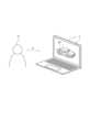
図1は、本実施形態の情報処理装置1の概略図である。ユーザP1は方向A1に、情報処理装置1のライトフィールドディスプレイ12を視認する。ライトフィールドディスプレイ12は、対象OBを立体的に(すなわち3次元で)表示する。Figure 1 is a schematic diagram of an information processing device 1 according to this embodiment. A user P1 views the
図2を参照して情報処理装置1の内部構成が詳細に説明される。The internal configuration of the information processing device 1 is described in detail with reference to FIG. 2.
情報処理装置1は、制御部11とライトフィールドディスプレイ12と記憶部13と撮像部14とを含む。情報処理装置1の各構成要素は、例えば専用線を介して互いに通信可能に接続される。The information processing device 1 includes a
制御部11は例えば、CPU(Central Processing Unit)又はMPU(Micro Processing Unit)を含む1つ以上の汎用プロセッサを含む。制御部11は、特定の処理に特化した1つ以上の専用プロセッサを含んでよい。制御部11は、プロセッサを含む代わりに、1つ以上の専用回路を含んでもよい。専用回路は例えば、FPGA(Field-Programmable Gate Array)、又はASIC(Application Specific Integrated Circuit)であってよい。制御部11は、ECU(Electronic Control Unit)を含んでもよい。The
ライトフィールドディスプレイ12は、対象OBがあたかもライトフィールドディスプレイ12上に実在するかのように、ユーザP1からの見る角度にかかわらず対象OBを立体的に表示する。ライトフィールドディスプレイ12は次の技術を利用する。
(1)リアルタイムでのセンシング(視線検出)技術
(2)リアルタイムでの光線レンダリング技術
(3)3Dディスプレイ技術 The
(1) Real-time sensing (gaze detection) technology (2) Real-time light rendering technology (3) 3D display technology
記憶部13は、例えば半導体メモリ、磁気メモリ、光メモリ、又はこれらのうち少なくとも2種類の組み合わせが含まれるが、これらに限られない。半導体メモリは、例えば、RAM又はROMである。RAMは、例えば、SRAM又はDRAMである。ROMは、例えば、EEPROMである。記憶部13は、例えば主記憶装置、補助記憶装置、又はキャッシュメモリとして機能してもよい。記憶部13は、制御部11によって分析又は処理された結果の情報を記憶してよい。記憶部13は、情報処理装置1の動作又は制御に関する各種情報等を記憶してよい。記憶部13は、システムプログラム、アプリケーションプログラム、及び組み込みソフトウェア等を記憶してよい。記憶部13は情報処理装置1の外部に設けられて、情報処理装置1からアクセスされてよい。The
撮像部14はカメラを含む。撮像部14は周囲を撮像することができる。撮像部14は画像解析のために、撮像した画像を記憶部13に記録し又は制御部11に送信してよい。画像は静止画又は動画を含む。The
本実施形態の情報処理装置1が実行する処理の概要が説明される。制御部11は、ライトフィールドディスプレイ12を用いて対象OBを表示し、撮像部14により、表示された対象OBに対するユーザP1の視線又は顔の向きを検出し、検出された視線又は顔の向きに対応するベクトルと、ユーザP1が見ている対象OBとの衝突点の深さに焦点を合わせる。この構成により情報処理装置1は、焦点を合わせた深さからのずれが大きいときのぼやけを低減することができる。The following describes an overview of the processing executed by the information processing device 1 of this embodiment. The
以下、情報処理装置1において実行される情報処理方法が詳細に説明される。The information processing method executed by the information processing device 1 is described in detail below.
制御部11は、ライトフィールドディスプレイ12を用いて対象OBを表示する。対象OBの少なくとも一部は、ライトフィールドディスプレイ12の表面とは異なる位置に立体的に表示される。The
制御部11は、撮像部14により、表示された対象OBに対するユーザP1の視線又は顔の向きを検出する。撮像部14は例えば、RGB/IRカメラであってよい。撮像部14は情報処理装置1に内蔵されてもよいし、外付けされてもよい。The
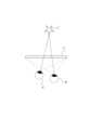
制御部11は、検出された視線又は顔の向きに対応するベクトルと、ユーザP1が見ている対象OBとの衝突点の深さに焦点を合わせる。例えばユーザP1が図1の対象OB(ここでは車両)のフロントガラスを見ていれば、フロントガラスに焦点を合わせる。この場合、図3に示されるように、制御部11はユーザP1の右目RE及び左目LEの焦点Fを、ライトフィールドディスプレイ12の表面とは異なる位置に設定する。The
図4を参照して、情報処理装置1による情報処理方法が説明される。The information processing method by the information processing device 1 is described with reference to Figure 4.
ステップS1にて制御部11は、ライトフィールドディスプレイ12を用いて対象OBを表示する。ステップS2にて制御部11は、撮像部14により、表示された対象OBに対するユーザP1の視線又は顔の向きを検出する。ステップS3にて制御部11は、検出された視線又は顔の向きに対応するベクトルと、ユーザP1が見ている対象OBとの衝突点の深さに焦点を合わせる。In step S1, the
以上述べたように本実施形態によれば、制御部11は、ライトフィールドディスプレイ12を用いて対象OBを表示し、撮像部14により、表示された対象OBに対するユーザP1の視線又は顔の向きを検出し、検出された視線又は顔の向きに対応するベクトルと、ユーザP1が見ている対象OBとの衝突点の深さに焦点を合わせる。この構成により情報処理装置1は、焦点を合わせた深さからのずれが大きいときのぼやけを低減することができる。As described above, according to this embodiment, the
また本実施形態によれば、制御部11の動作は、対象OBをライトフィールドディスプレイ12の表面とは異なる位置に表示することを含む。この構成により情報処理装置1は、対象OBを立体的に表示することができる。Furthermore, according to this embodiment, the operation of the
また本実施形態によれば、制御部11の動作は、焦点をライトフィールドディスプレイ12の表面とは異なる位置に設定することを含む。この構成により情報処理装置1は、適切な位置に焦点を合わせることができる。Furthermore, according to this embodiment, the operation of the
本開示が諸図面及び実施例に基づき説明されるが、当業者であれば本開示に基づき種々の変形及び改変を行ってもよいことに注意されたい。その他、本開示の趣旨を逸脱しない範囲での変更が可能である。例えば、各手段又は各ステップに含まれる機能等は論理的に矛盾しないように再配置可能であり、複数の手段又はステップを1つに組み合わせたり、或いは分割したりすることが可能である。Although the present disclosure is described based on various drawings and examples, it should be noted that a person skilled in the art may make various modifications and alterations based on the present disclosure. Other modifications are possible without departing from the spirit of the present disclosure. For example, the functions included in each means or step can be rearranged so as not to cause logical inconsistencies, and multiple means or steps can be combined into one or divided.
例えば、上記の実施形態において、情報処理装置1の機能又は処理の全部又は一部を実行するプログラムは、コンピュータで読取り可能な記録媒体に記録しておくことができる。コンピュータで読取り可能な記録媒体は、非一時的なコンピュータ読取可能な媒体を含み、例えば、磁気記録装置、光ディスク、光磁気記録媒体、又は半導体メモリである。プログラムの流通は、例えば、プログラムを記録したDVD(Digital Versatile Disc)又はCD-ROM(Compact Disc Read Only Memory)などの可搬型記録媒体を販売、譲渡、又は貸与することによって行う。またプログラムの流通は、プログラムを任意のサーバのストレージに格納しておき、任意のサーバから他のコンピュータにプログラムを送信することにより行ってもよい。またプログラムはプログラムプロダクトとして提供されてもよい。本開示は、プロセッサが実行可能なプログラムとしても実現可能である。For example, in the above embodiment, a program that executes all or part of the functions or processes of the information processing device 1 can be recorded on a computer-readable recording medium. The computer-readable recording medium includes a non-transitory computer-readable medium, such as a magnetic recording device, an optical disk, a magneto-optical recording medium, or a semiconductor memory. The program is distributed, for example, by selling, transferring, or lending a portable recording medium such as a DVD (Digital Versatile Disc) or a CD-ROM (Compact Disc Read Only Memory) on which the program is recorded. The program may also be distributed by storing the program in the storage of an arbitrary server and transmitting the program from the arbitrary server to another computer. The program may also be provided as a program product. The present disclosure can also be realized as a program executable by a processor.
1 情報処理装置1 Information processing device
Claims (4)
Translated fromJapanese前記ライトフィールドディスプレイを用いて対象を表示することと、
撮像部により、表示された前記対象に対するユーザの視線又は顔の向きを検出することと、
検出された前記視線又は前記顔の向きに対応するベクトルと、前記ユーザが見ている前記対象との衝突点の深さに焦点を合わせることと、
を含む動作を実行する、情報処理装置。 An information processing device including a control unit and a light field display, the control unit comprising:
displaying an object using the light field display; and
Detecting a line of sight or a facial direction of a user with respect to the displayed object by an imaging unit;
focusing on the depth of a collision point between a vector corresponding to the detected line of sight or face orientation and the object the user is looking at;
An information processing device that performs operations including the steps of:
前記対象を前記ライトフィールドディスプレイの表面とは異なる位置に表示することを含む、
情報処理装置。 2. The information processing device according to claim 1, wherein the operation is
displaying the object at a location different from a surface of the light field display.
Information processing device.
前記焦点を前記ライトフィールドディスプレイの表面とは異なる位置に設定することを含む、
情報処理装置。 2. The information processing device according to claim 1, wherein the operation is
setting the focal point at a location different from a surface of the light field display;
Information processing device.
前記撮像部は前記情報処理装置に内蔵され、又は外付けされる、
情報処理装置。
2. The information processing device according to claim 1,
The imaging unit is built into the information processing device or is externally attached thereto.
Information processing device.
Priority Applications (1)
| Application Number | Priority Date | Filing Date | Title |
|---|---|---|---|
| JP2023006061AJP2024101879A (en) | 2023-01-18 | 2023-01-18 | Information processing device |
Applications Claiming Priority (1)
| Application Number | Priority Date | Filing Date | Title |
|---|---|---|---|
| JP2023006061AJP2024101879A (en) | 2023-01-18 | 2023-01-18 | Information processing device |
Publications (1)
| Publication Number | Publication Date |
|---|---|
| JP2024101879Atrue JP2024101879A (en) | 2024-07-30 |
Family
ID=91968306
Family Applications (1)
| Application Number | Title | Priority Date | Filing Date |
|---|---|---|---|
| JP2023006061APendingJP2024101879A (en) | 2023-01-18 | 2023-01-18 | Information processing device |
Country Status (1)
| Country | Link |
|---|---|
| JP (1) | JP2024101879A (en) |
Citations (11)
| Publication number | Priority date | Publication date | Assignee | Title |
|---|---|---|---|---|
| JP2000354257A (en)* | 1999-06-10 | 2000-12-19 | Sony Corp | Image processor, image processing method and program provision medium |
| US20140035959A1 (en)* | 2012-08-04 | 2014-02-06 | Paul Lapstun | Light Field Display Device and Method |
| JP2014132433A (en)* | 2012-12-07 | 2014-07-17 | Canon Inc | Image creating device and image creating method |
| JP2015521298A (en)* | 2012-04-25 | 2015-07-27 | マイクロソフト コーポレーション | Light field projector based on movable LED array and microlens array for use in head mounted display |
| JP2017511017A (en)* | 2014-01-10 | 2017-04-13 | オステンド・テクノロジーズ・インコーポレーテッド | Method for a full parallax compressed light field 3D imaging system |
| JP2018509983A (en)* | 2015-03-16 | 2018-04-12 | マジック リープ,インコーポレイティド | Method and system for diagnosing and treating diseases that impair health |
| JP2019062390A (en)* | 2017-09-26 | 2019-04-18 | キヤノン株式会社 | INFORMATION PROCESSING APPARATUS, INFORMATION PROVIDING APPARATUS, CONTROL METHOD, AND PROGRAM |
| CN109979016A (en)* | 2019-03-26 | 2019-07-05 | 徐治国 | A kind of AR equipment shows method, AR equipment and the storage medium of light field image |
| JP2020512735A (en)* | 2017-03-08 | 2020-04-23 | オステンド・テクノロジーズ・インコーポレーテッド | Compression method and system for near-eye display |
| JP2020527872A (en)* | 2017-07-13 | 2020-09-10 | グーグル エルエルシー | Non-planar computational display |
| JP2022013882A (en)* | 2020-07-01 | 2022-01-18 | プキョン ナショナル ユニバーシティ インダストリー-ユニバーシティ コーポレーション ファウンデーション | Invisible light visualization Auto-matched augmented reality glass |
- 2023
- 2023-01-18JPJP2023006061Apatent/JP2024101879A/enactivePending
Patent Citations (11)
| Publication number | Priority date | Publication date | Assignee | Title |
|---|---|---|---|---|
| JP2000354257A (en)* | 1999-06-10 | 2000-12-19 | Sony Corp | Image processor, image processing method and program provision medium |
| JP2015521298A (en)* | 2012-04-25 | 2015-07-27 | マイクロソフト コーポレーション | Light field projector based on movable LED array and microlens array for use in head mounted display |
| US20140035959A1 (en)* | 2012-08-04 | 2014-02-06 | Paul Lapstun | Light Field Display Device and Method |
| JP2014132433A (en)* | 2012-12-07 | 2014-07-17 | Canon Inc | Image creating device and image creating method |
| JP2017511017A (en)* | 2014-01-10 | 2017-04-13 | オステンド・テクノロジーズ・インコーポレーテッド | Method for a full parallax compressed light field 3D imaging system |
| JP2018509983A (en)* | 2015-03-16 | 2018-04-12 | マジック リープ,インコーポレイティド | Method and system for diagnosing and treating diseases that impair health |
| JP2020512735A (en)* | 2017-03-08 | 2020-04-23 | オステンド・テクノロジーズ・インコーポレーテッド | Compression method and system for near-eye display |
| JP2020527872A (en)* | 2017-07-13 | 2020-09-10 | グーグル エルエルシー | Non-planar computational display |
| JP2019062390A (en)* | 2017-09-26 | 2019-04-18 | キヤノン株式会社 | INFORMATION PROCESSING APPARATUS, INFORMATION PROVIDING APPARATUS, CONTROL METHOD, AND PROGRAM |
| CN109979016A (en)* | 2019-03-26 | 2019-07-05 | 徐治国 | A kind of AR equipment shows method, AR equipment and the storage medium of light field image |
| JP2022013882A (en)* | 2020-07-01 | 2022-01-18 | プキョン ナショナル ユニバーシティ インダストリー-ユニバーシティ コーポレーション ファウンデーション | Invisible light visualization Auto-matched augmented reality glass |
Non-Patent Citations (1)
| Title |
|---|
| 鈴木 孝明 TAKAAKI SUZUKI: "被写界深度ボケと運動視差を同時に再現する注視反応ディスプレイ Gaze Reactive Display Simultaneously P", 情報処理学会研究報告 平成21年度▲2▼ [CD−ROM], JPN6025000116, 15 August 2009 (2009-08-15), JP, pages 1 - 8, ISSN: 0005502781* |
Similar Documents
| Publication | Publication Date | Title |
|---|---|---|
| JP2009129001A (en) | Driving support system, vehicle, solid object region estimation method | |
| CN111563924B (en) | Image depth determination method, living body identification method, circuit, device, and medium | |
| WO2013080697A1 (en) | Image processing device, image processing method and program | |
| CN111527374A (en) | Sight direction correction device, sight direction correction method, and sight direction correction program | |
| US12284438B2 (en) | Image processing device, image processing method and non-transitory computer-readable recording medium | |
| JP6669182B2 (en) | Occupant monitoring device | |
| JP5828024B2 (en) | 3D measuring device | |
| WO2020124517A1 (en) | Photographing equipment control method, photographing equipment control device and photographing equipment | |
| WO2018222122A1 (en) | Methods for perspective correction, computer program products and systems | |
| WO2019187283A1 (en) | Image processing device, image display system, and image processing method | |
| CN113056907A (en) | Imaging method, imaging device, and storage medium | |
| CN111186375B (en) | Electronic mirror system for vehicle | |
| KR20210150881A (en) | Electronic apparatus and operaintg method thereof | |
| US20220114748A1 (en) | System and Method for Capturing a Spatial Orientation of a Wearable Device | |
| TW202011154A (en) | Method and apparatus for pre-load display of object information | |
| JP2024101879A (en) | Information processing device | |
| JP5805013B2 (en) | Captured image display device, captured image display method, and program | |
| US7158665B2 (en) | Image processing device for stereo image processing | |
| US20230222727A1 (en) | Method and device for generating three-dimensional image by using plurality of cameras | |
| US20230217108A1 (en) | Image processing device, image processing method and non-transitory computer-readable recording medium | |
| WO2020079807A1 (en) | Object tracking device, object tracking method, and program | |
| JP2009077022A (en) | Driving support system and vehicle | |
| JP6024639B2 (en) | Gaze position detection device and gaze position detection method | |
| JP7040627B2 (en) | Calculator, information processing method and program | |
| CN111754558A (en) | Matching method for RGB-D camera system and binocular imaging system, system and computing system thereof |
Legal Events
| Date | Code | Title | Description |
|---|---|---|---|
| A621 | Written request for application examination | Free format text:JAPANESE INTERMEDIATE CODE: A621 Effective date:20240312 | |
| A977 | Report on retrieval | Free format text:JAPANESE INTERMEDIATE CODE: A971007 Effective date:20250106 | |
| A131 | Notification of reasons for refusal | Free format text:JAPANESE INTERMEDIATE CODE: A131 Effective date:20250114 | |
| A521 | Request for written amendment filed | Free format text:JAPANESE INTERMEDIATE CODE: A523 Effective date:20250128 | |
| A131 | Notification of reasons for refusal | Free format text:JAPANESE INTERMEDIATE CODE: A131 Effective date:20250507 | |
| A521 | Request for written amendment filed | Free format text:JAPANESE INTERMEDIATE CODE: A523 Effective date:20250616 |