JP2024079660A - Surgical retractor systems and components - Google Patents
Surgical retractor systems and componentsDownload PDFInfo
- Publication number
- JP2024079660A JP2024079660AJP2023202974AJP2023202974AJP2024079660AJP 2024079660 AJP2024079660 AJP 2024079660AJP 2023202974 AJP2023202974 AJP 2023202974AJP 2023202974 AJP2023202974 AJP 2023202974AJP 2024079660 AJP2024079660 AJP 2024079660A
- Authority
- JP
- Japan
- Prior art keywords
- retractor
- guide
- assembly
- shim
- mounting component
- Prior art date
- Legal status (The legal status is an assumption and is not a legal conclusion. Google has not performed a legal analysis and makes no representation as to the accuracy of the status listed.)
- Pending
Links
Images


Classifications
- A—HUMAN NECESSITIES
- A61—MEDICAL OR VETERINARY SCIENCE; HYGIENE
- A61B—DIAGNOSIS; SURGERY; IDENTIFICATION
- A61B17/00—Surgical instruments, devices or methods
- A61B17/02—Surgical instruments, devices or methods for holding wounds open, e.g. retractors; Tractors
- A61B17/0206—Surgical instruments, devices or methods for holding wounds open, e.g. retractors; Tractors with antagonistic arms as supports for retractor elements
- A—HUMAN NECESSITIES
- A61—MEDICAL OR VETERINARY SCIENCE; HYGIENE
- A61B—DIAGNOSIS; SURGERY; IDENTIFICATION
- A61B17/00—Surgical instruments, devices or methods
- A61B17/02—Surgical instruments, devices or methods for holding wounds open, e.g. retractors; Tractors
- A61B17/025—Joint distractors
- A—HUMAN NECESSITIES
- A61—MEDICAL OR VETERINARY SCIENCE; HYGIENE
- A61B—DIAGNOSIS; SURGERY; IDENTIFICATION
- A61B17/00—Surgical instruments, devices or methods
- A61B17/04—Surgical instruments, devices or methods for suturing wounds; Holders or packages for needles or suture materials
- A61B17/0401—Suture anchors, buttons or pledgets, i.e. means for attaching sutures to bone, cartilage or soft tissue; Instruments for applying or removing suture anchors
- A—HUMAN NECESSITIES
- A61—MEDICAL OR VETERINARY SCIENCE; HYGIENE
- A61B—DIAGNOSIS; SURGERY; IDENTIFICATION
- A61B17/00—Surgical instruments, devices or methods
- A61B17/56—Surgical instruments or methods for treatment of bones or joints; Devices specially adapted therefor
- A61B17/58—Surgical instruments or methods for treatment of bones or joints; Devices specially adapted therefor for osteosynthesis, e.g. bone plates, screws or setting implements
- A61B17/68—Internal fixation devices, including fasteners and spinal fixators, even if a part thereof projects from the skin
- A61B17/70—Spinal positioners or stabilisers, e.g. stabilisers comprising fluid filler in an implant
- A61B17/7074—Tools specially adapted for spinal fixation operations other than for bone removal or filler handling
- A61B17/7076—Tools specially adapted for spinal fixation operations other than for bone removal or filler handling for driving, positioning or assembling spinal clamps or bone anchors specially adapted for spinal fixation
- A61B17/7077—Tools specially adapted for spinal fixation operations other than for bone removal or filler handling for driving, positioning or assembling spinal clamps or bone anchors specially adapted for spinal fixation for moving bone anchors attached to vertebrae, thereby displacing the vertebrae
- A—HUMAN NECESSITIES
- A61—MEDICAL OR VETERINARY SCIENCE; HYGIENE
- A61B—DIAGNOSIS; SURGERY; IDENTIFICATION
- A61B90/00—Instruments, implements or accessories specially adapted for surgery or diagnosis and not covered by any of the groups A61B1/00 - A61B50/00, e.g. for luxation treatment or for protecting wound edges
- A61B90/50—Supports for surgical instruments, e.g. articulated arms
- A—HUMAN NECESSITIES
- A61—MEDICAL OR VETERINARY SCIENCE; HYGIENE
- A61F—FILTERS IMPLANTABLE INTO BLOOD VESSELS; PROSTHESES; DEVICES PROVIDING PATENCY TO, OR PREVENTING COLLAPSING OF, TUBULAR STRUCTURES OF THE BODY, e.g. STENTS; ORTHOPAEDIC, NURSING OR CONTRACEPTIVE DEVICES; FOMENTATION; TREATMENT OR PROTECTION OF EYES OR EARS; BANDAGES, DRESSINGS OR ABSORBENT PADS; FIRST-AID KITS
- A61F2/00—Filters implantable into blood vessels; Prostheses, i.e. artificial substitutes or replacements for parts of the body; Appliances for connecting them with the body; Devices providing patency to, or preventing collapsing of, tubular structures of the body, e.g. stents
- A61F2/02—Prostheses implantable into the body
- A61F2/30—Joints
- A61F2/44—Joints for the spine, e.g. vertebrae, spinal discs
- A61F2/442—Intervertebral or spinal discs, e.g. resilient
- A—HUMAN NECESSITIES
- A61—MEDICAL OR VETERINARY SCIENCE; HYGIENE
- A61B—DIAGNOSIS; SURGERY; IDENTIFICATION
- A61B17/00—Surgical instruments, devices or methods
- A61B17/02—Surgical instruments, devices or methods for holding wounds open, e.g. retractors; Tractors
- A61B17/0293—Surgical instruments, devices or methods for holding wounds open, e.g. retractors; Tractors with ring member to support retractor elements
- A—HUMAN NECESSITIES
- A61—MEDICAL OR VETERINARY SCIENCE; HYGIENE
- A61B—DIAGNOSIS; SURGERY; IDENTIFICATION
- A61B17/00—Surgical instruments, devices or methods
- A61B17/16—Instruments for performing osteoclasis; Drills or chisels for bones; Trepans
- A61B17/17—Guides or aligning means for drills, mills, pins or wires
- A61B17/1739—Guides or aligning means for drills, mills, pins or wires specially adapted for particular parts of the body
- A61B17/1757—Guides or aligning means for drills, mills, pins or wires specially adapted for particular parts of the body for the spine
- A—HUMAN NECESSITIES
- A61—MEDICAL OR VETERINARY SCIENCE; HYGIENE
- A61B—DIAGNOSIS; SURGERY; IDENTIFICATION
- A61B17/00—Surgical instruments, devices or methods
- A61B17/56—Surgical instruments or methods for treatment of bones or joints; Devices specially adapted therefor
- A61B17/58—Surgical instruments or methods for treatment of bones or joints; Devices specially adapted therefor for osteosynthesis, e.g. bone plates, screws or setting implements
- A61B17/68—Internal fixation devices, including fasteners and spinal fixators, even if a part thereof projects from the skin
- A61B17/84—Fasteners therefor or fasteners being internal fixation devices
- A61B17/86—Pins or screws or threaded wires; nuts therefor
- A61B17/8625—Shanks, i.e. parts contacting bone tissue
- A61B17/863—Shanks, i.e. parts contacting bone tissue with thread interrupted or changing its form along shank, other than constant taper
- A—HUMAN NECESSITIES
- A61—MEDICAL OR VETERINARY SCIENCE; HYGIENE
- A61B—DIAGNOSIS; SURGERY; IDENTIFICATION
- A61B17/00—Surgical instruments, devices or methods
- A61B2017/00477—Coupling
- A—HUMAN NECESSITIES
- A61—MEDICAL OR VETERINARY SCIENCE; HYGIENE
- A61B—DIAGNOSIS; SURGERY; IDENTIFICATION
- A61B17/00—Surgical instruments, devices or methods
- A61B17/02—Surgical instruments, devices or methods for holding wounds open, e.g. retractors; Tractors
- A61B17/025—Joint distractors
- A61B2017/0256—Joint distractors for the spine
- A—HUMAN NECESSITIES
- A61—MEDICAL OR VETERINARY SCIENCE; HYGIENE
- A61B—DIAGNOSIS; SURGERY; IDENTIFICATION
- A61B17/00—Surgical instruments, devices or methods
- A61B17/04—Surgical instruments, devices or methods for suturing wounds; Holders or packages for needles or suture materials
- A61B17/0401—Suture anchors, buttons or pledgets, i.e. means for attaching sutures to bone, cartilage or soft tissue; Instruments for applying or removing suture anchors
- A61B2017/0409—Instruments for applying suture anchors
- A—HUMAN NECESSITIES
- A61—MEDICAL OR VETERINARY SCIENCE; HYGIENE
- A61B—DIAGNOSIS; SURGERY; IDENTIFICATION
- A61B17/00—Surgical instruments, devices or methods
- A61B17/04—Surgical instruments, devices or methods for suturing wounds; Holders or packages for needles or suture materials
- A61B17/0401—Suture anchors, buttons or pledgets, i.e. means for attaching sutures to bone, cartilage or soft tissue; Instruments for applying or removing suture anchors
- A61B2017/0414—Suture anchors, buttons or pledgets, i.e. means for attaching sutures to bone, cartilage or soft tissue; Instruments for applying or removing suture anchors having a suture-receiving opening, e.g. lateral opening
- A—HUMAN NECESSITIES
- A61—MEDICAL OR VETERINARY SCIENCE; HYGIENE
- A61B—DIAGNOSIS; SURGERY; IDENTIFICATION
- A61B17/00—Surgical instruments, devices or methods
- A61B17/04—Surgical instruments, devices or methods for suturing wounds; Holders or packages for needles or suture materials
- A61B17/0401—Suture anchors, buttons or pledgets, i.e. means for attaching sutures to bone, cartilage or soft tissue; Instruments for applying or removing suture anchors
- A61B2017/042—Suture anchors, buttons or pledgets, i.e. means for attaching sutures to bone, cartilage or soft tissue; Instruments for applying or removing suture anchors plastically deformed during insertion
- A61B2017/0422—Suture anchors, buttons or pledgets, i.e. means for attaching sutures to bone, cartilage or soft tissue; Instruments for applying or removing suture anchors plastically deformed during insertion by insertion of a separate member into the body of the anchor
- A61B2017/0424—Suture anchors, buttons or pledgets, i.e. means for attaching sutures to bone, cartilage or soft tissue; Instruments for applying or removing suture anchors plastically deformed during insertion by insertion of a separate member into the body of the anchor the separate member staying in the anchor after placement
- A—HUMAN NECESSITIES
- A61—MEDICAL OR VETERINARY SCIENCE; HYGIENE
- A61B—DIAGNOSIS; SURGERY; IDENTIFICATION
- A61B17/00—Surgical instruments, devices or methods
- A61B17/04—Surgical instruments, devices or methods for suturing wounds; Holders or packages for needles or suture materials
- A61B17/0401—Suture anchors, buttons or pledgets, i.e. means for attaching sutures to bone, cartilage or soft tissue; Instruments for applying or removing suture anchors
- A61B2017/0427—Suture anchors, buttons or pledgets, i.e. means for attaching sutures to bone, cartilage or soft tissue; Instruments for applying or removing suture anchors having anchoring barbs or pins extending outwardly from the anchor body
- A61B2017/0437—Suture anchors, buttons or pledgets, i.e. means for attaching sutures to bone, cartilage or soft tissue; Instruments for applying or removing suture anchors having anchoring barbs or pins extending outwardly from the anchor body the barbs being resilient or spring-like
- A—HUMAN NECESSITIES
- A61—MEDICAL OR VETERINARY SCIENCE; HYGIENE
- A61B—DIAGNOSIS; SURGERY; IDENTIFICATION
- A61B17/00—Surgical instruments, devices or methods
- A61B17/04—Surgical instruments, devices or methods for suturing wounds; Holders or packages for needles or suture materials
- A61B17/0401—Suture anchors, buttons or pledgets, i.e. means for attaching sutures to bone, cartilage or soft tissue; Instruments for applying or removing suture anchors
- A61B2017/044—Suture anchors, buttons or pledgets, i.e. means for attaching sutures to bone, cartilage or soft tissue; Instruments for applying or removing suture anchors with a threaded shaft, e.g. screws
- A—HUMAN NECESSITIES
- A61—MEDICAL OR VETERINARY SCIENCE; HYGIENE
- A61B—DIAGNOSIS; SURGERY; IDENTIFICATION
- A61B17/00—Surgical instruments, devices or methods
- A61B17/04—Surgical instruments, devices or methods for suturing wounds; Holders or packages for needles or suture materials
- A61B17/0401—Suture anchors, buttons or pledgets, i.e. means for attaching sutures to bone, cartilage or soft tissue; Instruments for applying or removing suture anchors
- A61B2017/0446—Means for attaching and blocking the suture in the suture anchor
- A61B2017/0458—Longitudinal through hole, e.g. suture blocked by a distal suture knot
- A—HUMAN NECESSITIES
- A61—MEDICAL OR VETERINARY SCIENCE; HYGIENE
- A61B—DIAGNOSIS; SURGERY; IDENTIFICATION
- A61B90/00—Instruments, implements or accessories specially adapted for surgery or diagnosis and not covered by any of the groups A61B1/00 - A61B50/00, e.g. for luxation treatment or for protecting wound edges
- A61B90/50—Supports for surgical instruments, e.g. articulated arms
- A61B2090/5025—Supports for surgical instruments, e.g. articulated arms with a counter-balancing mechanism
- A61B2090/504—Supports for surgical instruments, e.g. articulated arms with a counter-balancing mechanism with a counterweight
Landscapes
- Health & Medical Sciences (AREA)
- Life Sciences & Earth Sciences (AREA)
- Surgery (AREA)
- Engineering & Computer Science (AREA)
- Biomedical Technology (AREA)
- General Health & Medical Sciences (AREA)
- Neurology (AREA)
- Orthopedic Medicine & Surgery (AREA)
- Veterinary Medicine (AREA)
- Heart & Thoracic Surgery (AREA)
- Public Health (AREA)
- Animal Behavior & Ethology (AREA)
- Molecular Biology (AREA)
- Medical Informatics (AREA)
- Nuclear Medicine, Radiotherapy & Molecular Imaging (AREA)
- Oral & Maxillofacial Surgery (AREA)
- Cardiology (AREA)
- Transplantation (AREA)
- Vascular Medicine (AREA)
- Pathology (AREA)
- Rheumatology (AREA)
- Surgical Instruments (AREA)
Abstract
Description
Translated fromJapanese(関連出願の相互参照)
本出願は、2022年11月30日出願の米国特許仮出願第63/428,861号、2023年2月24日出願の米国特許仮出願第63/486,847号の優先権を主張し、それらの全内容は、各々、その全体が本明細書に記載されているかのように参照により本開示に明示的に組み込まれる。CROSS-REFERENCE TO RELATED APPLICATIONS
This application claims priority to U.S. Provisional Patent Application No. 63/428,861, filed November 30, 2022, and U.S. Provisional Patent Application No. 63/486,847, filed February 24, 2023, the entire contents of each of which are expressly incorporated by reference into this disclosure as if set forth in their entirety herein.
多種多様な外科用医療デバイスが存在する。これらのデバイスのうちのいくつかは、外科用開創器、外科用開創器システム、外科用開創器安定化システムなどを含む。既知の外科用医療デバイスの各々は、特定の利点及び欠点を有する。代替的な外科用医療デバイスを提供することが引き続き必要とされている。A wide variety of surgical medical devices exist. Some of these devices include surgical retractors, surgical retractor systems, surgical retractor stabilization systems, and the like. Each of the known surgical medical devices has certain advantages and disadvantages. There is a continuing need to provide alternative surgical medical devices.
本開示は、医療デバイスのための設計、材料、製造方法、及び使用の代替案を提供する。例示的なアセンブリは、シム本体と、シム本体に結合されたガイドと、を含み得、シム本体は、開創器アセンブリの開創器ブレードに解放可能に結合するように構成された外科用シム本体であり得、ガイドは、取り付け構成要素を受容し、かつ開創器ブレードが対象内に外科用通路を形成しているときに、取り付け構成要素の遠位端を対象の椎骨組織に向けるように構成され得る。The present disclosure provides design, material, manufacturing, and use alternatives for a medical device. An exemplary assembly may include a shim body and a guide coupled to the shim body, where the shim body may be a surgical shim body configured to releasably couple to a retractor blade of a retractor assembly, and the guide may be configured to receive an attachment component and direct a distal end of the attachment component toward vertebral tissue of a subject when the retractor blade is forming a surgical passage in the subject.
このセクションの実施形態のいずれかに代えて、又はそれに加えて、ガイドが、シム本体の中心長手方向軸からオフセットされ得る。Alternatively or in addition to any of the embodiments in this section, the guide may be offset from the central longitudinal axis of the shim body.
このセクションの実施形態のいずれかに代えて、又はそれに加えて、ガイドが、シム本体に対して固定され得る。Alternatively or in addition to any of the embodiments in this section, the guide may be fixed relative to the shim body.
このセクションの実施形態のいずれかに代えて、又はそれに加えて、ガイドが、シム本体に対して内向き及び外向きに並進するように構成され得る。Alternatively or in addition to any of the embodiments in this section, the guide may be configured to translate inwardly and outwardly relative to the shim body.
このセクションの実施形態のいずれかに代えて、又はそれに加えて、ガイドが、シム本体の長手方向軸に垂直な軸を中心としてシム本体に対して枢動するように構成され得る。Alternatively or in addition to any of the embodiments in this section, the guide may be configured to pivot relative to the shim body about an axis perpendicular to the longitudinal axis of the shim body.
このセクションの実施形態のいずれかに代えて、又はそれに加えて、ガイドが、近位端及び遠位端を有し得、ガイドチューブが、近位端から遠位端までの長さの少なくとも一部に延在し得る。Alternatively or in addition to any of the embodiments in this section, the guide may have a proximal end and a distal end, and the guide tube may extend at least a portion of its length from the proximal end to the distal end.
このセクションの実施形態のいずれかに代えて、又はそれに加えて、ガイドが、近位端、遠位端、及び近位端に近接したねじ山を有する。Alternatively or in addition to any of the embodiments in this section, the guide has a proximal end, a distal end, and a thread proximate the proximal end.
このセクションの実施形態のいずれかに代えて、又はそれに加えて、ガイドが、近位端及び遠位端を有し得、ガイドの近位端が、シム本体の遠位端の近位にあり得、ガイドの遠位端が、シム本体の遠位端の遠位にあり得る。Alternatively or in addition to any of the embodiments in this section, the guide may have a proximal end and a distal end, the proximal end of the guide may be proximal to the distal end of the shim body, and the distal end of the guide may be distal to the distal end of the shim body.
このセクションの実施形態のいずれかに代えて、又はそれに加えて、シム本体の遠位端は、シム本体が開創器ブレードに解放可能に結合される場所の遠位の場所で、開創器ブレードに結合される椎間坂内シムの近位端と係合するように構成され得る。Alternatively or in addition to any of the embodiments in this section, the distal end of the shim body may be configured to engage a proximal end of an intravertebral shim that is coupled to the retractor blade at a location distal to where the shim body is releasably coupled to the retractor blade.
このセクションの実施形態のいずれかに代えて、又はそれに加えて、アセンブリが、取り付け構成要素を含み得、取り付け構成要素が、ガイドに解放可能に結合するように構成され得る。Alternatively or in addition to any of the embodiments in this section, the assembly may include an attachment component, which may be configured to releasably couple to the guide.
このセクションの実施形態のいずれかに代えて、又はそれに加えて、取り付け構成要素は、開創器アセンブリが腹臥位の対象と側方外科用通路を形成している間に、対象の脊椎の移動に対して開創器アセンブリを安定化するために、対象の椎骨組織と解放可能に係合するように構成され得る。Alternatively or in addition to any of the embodiments in this section, the attachment component may be configured to releasably engage vertebral tissue of the subject to stabilize the retractor assembly against movement of the subject's spine while the retractor assembly is forming a lateral surgical corridor with the subject in a prone position.
このセクションの実施形態のいずれかに代えて、又はそれに加えて、取り付け構成要素が、ねじ山付きであり得る。Alternatively or in addition to any of the embodiments in this section, the mounting component may be threaded.
このセクションの実施形態のいずれかに代えて、又はそれに加えて、取り付け構成要素が、取り付け構成要素の遠位端にねじ山を含み得、取り付け構成要素の遠位端のねじ山が、対象の椎骨組織と解放可能に係合するように構成されている。Alternatively or in addition to any of the embodiments in this section, the attachment component may include threads on a distal end of the attachment component, the threads on the distal end of the attachment component being configured to releasably engage vertebral tissue of the target.
このセクションの実施形態のいずれかに代えて、又はそれに加えて、取り付け構成要素が、取り付け構成要素の遠位端の近位の場所にねじ山を含み得、取り付け構成要素の遠位端の近位の場所にあるねじ山が、ガイド上のねじ山と係合するように構成されている。Alternatively or in addition to any of the embodiments in this section, the mounting component may include threads at a location proximal to the distal end of the mounting component, the threads at the location proximal to the distal end of the mounting component configured to engage threads on the guide.
このセクションの実施形態のいずれかに代えて、又はそれに加えて、取り付け構成要素が、取り付け構成要素の遠位端に第1のねじ山セットと、第1のねじ山セットの近位の場所に第2のねじ山セットと、を含み得る。Alternatively or in addition to any of the embodiments in this section, the mounting component may include a first set of threads at a distal end of the mounting component and a second set of threads at a location proximal to the first set of threads.
このセクションの実施形態のいずれかに代えて、又はそれに加えて、第1のねじ山セットが、第1のねじ山付き構成を有し得、第2のねじ山セットが、第2のねじ山付き構成を有し得る。Alternatively or in addition to any of the embodiments in this section, the first thread set can have a first threaded configuration and the second thread set can have a second threaded configuration.
このセクションの実施形態のいずれかに代えて、又はそれに加えて、第1のねじ山セットが、ガイドのねじ山と解放可能に係合するように構成され得、第1のねじ山セットがガイドのねじ山と解放可能に係合されたとき、第2のねじ山セットの遠位端がガイドによって覆われ得る。Alternatively or in addition to any of the embodiments in this section, the first thread set may be configured to releasably engage the threads of the guide, and a distal end of the second thread set may be covered by the guide when the first thread set is releasably engaged with the threads of the guide.
このセクションの実施形態のいずれかに代えて、又はそれに加えて、ガイドが、ガイドのガイドチューブの内径を画定する近位端を含み得、取り付け構成要素の近位端が、ガイドチューブの内径よりも大きい第1の外径を画定し得る。Alternatively or in addition to any of the embodiments in this section, the guide may include a proximal end that defines an inner diameter of a guide tube of the guide, and the proximal end of the mounting component may define a first outer diameter that is greater than the inner diameter of the guide tube.
このセクションの実施形態のいずれかに代えて、又はそれに加えて、取り付け構成要素が、ガイドチューブの内径未満である第2の外径を含み得、ガイドの近位端は、取り付け構成要素が対象の椎骨組織と係合しているときに、取り付け構成要素の第1の外径と第2の外径との間の移行部から調整可能に離隔されるように構成され得る。Alternatively or in addition to any of the embodiments in this section, the attachment component may include a second outer diameter that is less than the inner diameter of the guide tube, and the proximal end of the guide may be configured to be adjustably spaced from the transition between the first and second outer diameters of the attachment component when the attachment component is engaged with the target vertebral tissue.
例示的なシステムは、対象の脊椎への手術用通路を確立するように構成された開創器アセンブリと、開創器アセンブリに解放可能に結合され、開創器アセンブリが手術用通路を確立している間に対象の椎間板組織と係合するように構成されている、第1の安定器と、開創器アセンブリに解放可能に結合され、開創器アセンブリが手術用通路を確立している間に対象の椎骨組織と係合するように構成される、第2の安定器と、を含み得る。An exemplary system may include a retractor assembly configured to establish a surgical pathway to a spine of a subject, a first stabilizer releasably coupled to the retractor assembly and configured to engage disc tissue of the subject while the retractor assembly is establishing the surgical pathway, and a second stabilizer releasably coupled to the retractor assembly and configured to engage vertebral tissue of the subject while the retractor assembly is establishing the surgical pathway.
このセクションの実施形態のいずれかに代えて、又はそれに加えて、第1の安定器が、第1のシムを含み得、第2の安定器が、第2のシムを含み得、第2のシムの遠位端が、第1のシムの近位端と係合するように構成され得る。Alternatively or in addition to any of the embodiments in this section, the first stabilizer may include a first shim and the second stabilizer may include a second shim, with a distal end of the second shim configured to engage a proximal end of the first shim.
このセクションの実施形態のいずれかに代えて、又はそれに加えて、第2の安定器が、シム本体及びガイドを含み得る。Alternatively or in addition to any of the embodiments in this section, the second stabilizer may include a shim body and a guide.
このセクションの実施形態のいずれかに代えて、又はそれに加えて、開創器アセンブリが、開創器ブレードを含み得、シム本体が、開創器ブレードと係合するように構成され得る。Alternatively or in addition to any of the embodiments in this section, the retractor assembly can include a retractor blade and the shim body can be configured to engage the retractor blade.
このセクションの実施形態のいずれかに代えて、又はそれに加えて、ガイドが、シム本体に結合され得、かつ開創器ブレードの長手方向軸からオフセットされている。Alternatively or in addition to any of the embodiments in this section, the guide may be coupled to the shim body and offset from the longitudinal axis of the retractor blade.
このセクションの実施形態のいずれかに代えて、又はそれに加えて、ガイドが、シム本体に対して固定されるように構成され得る。Alternatively or in addition to any of the embodiments in this section, the guide may be configured to be fixed relative to the shim body.
このセクションの実施形態のいずれかに代えて、又はそれに加えて、ガイドが、シム本体及び開創器ブレードに対して調整されるように構成されている。Alternatively or in addition to any of the embodiments in this section, the guide is configured to adjust relative to the shim body and retractor blade.
このセクションの実施形態のいずれかに代えて、又はそれに加えて、第2の安定器が、取り付け構成要素を含み得、取り付け構成要素が、ガイドに解放可能に結合するように構成され得る。Alternatively or in addition to any of the embodiments in this section, the second stabilizer may include an attachment component, which may be configured to releasably couple to the guide.
このセクションの実施形態のいずれかに代えて、又はそれに加えて、取り付け構成要素は、開創器アセンブリが腹臥位の対象と側方外科用通路を確立している間に、対象の脊椎の移動に対して開創器アセンブリを安定化するために、対象の椎骨組織と解放可能に係合するように構成され得る。Alternatively or in addition to any of the embodiments in this section, the attachment component may be configured to releasably engage vertebral tissue of the subject to stabilize the retractor assembly against movement of the subject's spine while the retractor assembly establishes a lateral surgical corridor with the subject in a prone position.
このセクションの実施形態のいずれかに代えて、又はそれに加えて、ガイド、シム本体、及び開創器アセンブリは、取り付け構成要素が対象の椎骨組織と解放可能に係合されるときに、取り付け構成要素の軸に対して調整するように構成され得る。Alternatively or in addition to any of the embodiments in this section, the guide, shim body, and retractor assembly may be configured to adjust relative to the axis of the mounting component when the mounting component is releasably engaged with the target vertebral tissue.
例示的な方法は、第1の安定器を腹臥位の対象の椎間板組織と係合させることであって、第1の安定器が、開創器アセンブリと結合される、係合させることと、開創器アセンブリを使用して、対象内に側方外科用通路を形成することと、第2の安定器を対象の椎骨組織と係合させることであって、第2の安定器が、開創器アセンブリと結合される、係合させることと、を含み得る。An exemplary method may include engaging a first stabilizer with disc tissue of a subject in a prone position, where the first stabilizer is coupled to a retractor assembly, forming a lateral surgical passage in the subject using the retractor assembly, and engaging a second stabilizer with vertebral tissue of the subject, where the second stabilizer is coupled to the retractor assembly.
このセクションの実施形態のいずれかに代えて、又はそれに加えて、第2の安定器が、開創器アセンブリのブレードと係合するように構成されたシム本体と、シム本体に結合されたガイドと、ガイドを通して挿入され、対象の椎骨組織と係合されるように構成された取り付け構成要素と、を含み得る。Alternatively or in addition to any of the embodiments in this section, the second stabilizer may include a shim body configured to engage a blade of the retractor assembly, a guide coupled to the shim body, and an attachment component configured to be inserted through the guide and engaged with the target vertebral tissue.
このセクションの実施形態のいずれかに代えて、又はそれに加えて、方法は、取り付け構成要素の第1のねじ山セットをガイドのねじ山と係合させることを含み得、取り付け構成要素の第2のねじ山セットの遠位端は、取り付け構成要素の第1のねじ山セットがガイドのねじ山と係合されたときに、ガイドによって覆われ得る。Alternatively or in addition to any of the embodiments in this section, the method may include engaging a first set of threads on the mounting component with threads on the guide, and a distal end of a second set of threads on the mounting component may be covered by the guide when the first set of threads on the mounting component is engaged with the threads on the guide.
このセクションの実施形態のいずれかに代えて、又はそれに加えて、方法は、取り付け構成要素の第2のねじ山セットがガイドによって覆われている間に、シム本体を開創器アセンブリのブレードと係合させることを含み得る。Alternatively or in addition to any of the embodiments in this section, the method may include engaging the shim body with a blade of the retractor assembly while the second set of threads of the attachment component is covered by the guide.
このセクションの実施形態のいずれかに代えて、又はそれに加えて、シム本体を開創器アセンブリのブレードと係合させることが、第1の安定器を椎間板組織と係合させた後に行われ得る。Alternatively or in addition to any of the embodiments in this section, engaging the shim body with the blades of the retractor assembly may occur after engaging the first stabilizer with the disc tissue.
このセクションの実施形態のいずれかに代えて、又はそれに加えて、方法は、取り付け構成要素をガイドのねじ山を通して対象の椎骨組織内にねじ込むことを含み得る。Alternatively or in addition to any of the embodiments in this section, the method may include screwing an attachment component through threads of the guide and into vertebral tissue of the subject.
このセクションの実施形態のいずれかに代えて、又はそれに加えて、取り付け構成要素は、所定の距離が取り付け構成要素のヘッドの遠位ショルダとガイドのガイドチューブの近位端との間になるまで、対象の椎骨組織内にねじ込まれ得る。Alternatively or in addition to any of the embodiments in this section, the mounting component may be screwed into the target vertebral tissue until a predetermined distance is between the distal shoulder of the head of the mounting component and the proximal end of the guide tube of the guide.
このセクションの実施形態のいずれかに代えて、又はそれに加えて、方法は、取り付け構成要素を回転させて、取り付け構成要素を対象の椎骨組織から係合解除することを含み得る。Alternatively or in addition to any of the embodiments in this section, the method may include rotating the attachment component to disengage the attachment component from the target vertebral tissue.
このセクションの実施形態のいずれかに代えて、又はそれに加えて、方法は、第2の安定器を側方外科用通路から引き抜くことを含み得る。Alternatively or in addition to any of the embodiments in this section, the method may include withdrawing the second stabilizer from the lateral surgical corridor.
このセクションの実施形態のいずれかに代えて、又はそれに加えて、第2の安定器を側方外科用通路から引き抜くことが、シム本体を開創器アセンブリのブレードから係合解除することを含み得る。Alternatively or in addition to any of the embodiments in this section, withdrawing the second stabilizer from the lateral surgical channel may include disengaging the shim body from the blades of the retractor assembly.
いくつかの実施形態の上記の概要は、本開示の各開示された実施形態又は全ての実施態様を説明することを意図していない。以下の図面及び詳細な説明は、これらの実施形態をより具体的に例示する。The above summary of some embodiments is not intended to describe each disclosed embodiment or every implementation of the present disclosure. The figures and detailed description that follow more particularly exemplify these embodiments.
本開示は、添付の図面と関連する以下の詳細な説明の考慮において、より完全に理解され得る。
本開示は、様々な修正形態及び代替形態を受け入れることができるが、それらの詳細は、例として図面に示されており、詳細に説明されることになる。しかしながら、その意図は、説明される特定の実施形態に本開示を限定することではないことを理解されたい。逆に、本発明は、本開示の趣旨及び範囲内に収まる全ての修正物、均等物、及び代替物を包含するものである。The present disclosure is susceptible to various modifications and alternative forms, details of which have been shown by way of example in the drawings and will be described in detail. It should be understood, however, that the intention is not to limit the disclosure to the particular embodiments described. On the contrary, the invention is intended to cover all modifications, equivalents, and alternatives falling within the spirit and scope of the present disclosure.
脊椎は、可動性、支持、及びバランスを提供する。例えば、脊椎は、脳から身体の残りの部分に命令を伝達し、首の下の神経から脳に感覚情報を伝達する、脊髄の神経を保護する。小さな脊髄損傷であっても患者を衰弱させる可能性があり、大きな脊髄損傷は壊滅的である可能性がある。体重を支える能力又は柔軟性を可能にする能力の喪失は、患者を動けなくする可能性がある。それほど重篤ではない場合であっても、脊椎の小さな不規則性は、脊髄に接続された神経に圧力をかける可能性があり、痛烈な疼痛及び協調運動障害を引き起こす。The spine provides mobility, support, and balance. For example, it protects the nerves in the spinal cord, which transmit commands from the brain to the rest of the body and transmits sensory information from the nerves down the neck to the brain. Even small spinal cord injuries can be debilitating, and large spinal cord injuries can be devastating. Loss of the ability to bear weight or allow flexibility can leave a patient immobile. Even in less severe cases, small irregularities in the spine can put pressure on the nerves connected to the spinal cord, causing excruciating pain and loss of coordination.
様々な脊髄状態に対処するために、脊髄手術などのいくつかの医療処置が実施され得る。例えば、脊椎固定術は、損傷した椎間板の症状を軽減するために、又は治療として直接的な脊髄減圧を示唆することになる任意の病状のために実施される医療処置である。脊椎固定処置の主な目的は、損傷した椎間板の両側の椎骨間に安定性を提供し、それらの隣接する椎骨の自然な固定を促進することである。Several medical procedures, such as spinal surgery, may be performed to address various spinal conditions. For example, spinal fusion is a medical procedure performed to alleviate symptoms of a damaged disc or for any medical condition that would suggest direct spinal decompression as a treatment. The primary goal of a spinal fusion procedure is to provide stability between the vertebrae on either side of the damaged disc and promote the natural fusion of those adjacent vertebrae.
脊椎固定処置は、最小侵襲又は最小アクセス技術を介して実施され得る(従来の「切開」外科技術とは対照的に)。いくつかの事例では、切開外科技術は、典型的には、外科的標的部位へのアクセスを得るために、大きな切開及び大量の組織変位を必要とするという点で、概して望ましくない場合があり、それは、同時に、大量の疼痛、入院の長期化(医療費の増加)、及び患者集団における高い死亡率をもたらし得る。しかしながら、低侵襲性外科技術(いわゆる「最小アクセス」及び「最小侵襲」技術を含む)は、大幅に低減された組織変位要件を伴って、実質的により小さいサイズの切開を介して外科的標的部位にアクセスすることを伴うため、好ましいものであり得る。これは、結果的に、そのような処置と関連付けられた疼痛、死亡率、及び費用を低減する。Spinal fixation procedures may be performed via minimally invasive or minimal access techniques (as opposed to traditional "open" surgical techniques). In some cases, open surgical techniques may be generally undesirable in that they typically require large incisions and significant tissue displacement to gain access to the surgical target site, which may result in significant pain, prolonged hospital stays (increased healthcare costs), and high mortality in the patient population. However, minimally invasive surgical techniques (including so-called "minimal access" and "minimally invasive" techniques) may be preferable because they involve accessing the surgical target site via a substantially smaller sized incision with greatly reduced tissue displacement requirements. This, in turn, reduces the pain, mortality, and costs associated with such procedures.
いくつかの低侵襲性外科技術は、腰椎への側方アクセス手術用通路を作成するために最適化された外科用システム及び方法を利用することを含み得る。側方アクセスアプローチを利用しながら採用される外科用システム及び方法の改善は、手術時間を更に短縮し、側方アプローチのための用途を拡張し、処置の外科医採用を増加させ得、それらの全ては、最終的に、患者の病気の最小侵襲外科的矯正のためのより多くの機会を提供することによって、患者に利益をもたらし得る。Some minimally invasive surgical techniques may involve utilizing surgical systems and methods optimized to create a lateral access surgical corridor to the lumbar spine. Improvements in surgical systems and methods employed while utilizing a lateral access approach may further reduce operative time, expand the uses for the lateral approach, and increase surgeon adoption of the procedure, all of which may ultimately benefit patients by providing more opportunities for minimally invasive surgical correction of their ailments.
いくつかの例では、側方アクセスアプローチによる脊椎手術は、外科用開創器システムを利用して、1つ以上の外科用開創器ブレードを操作して、腹臥位で横たわっている患者の側方側を通る手術用通路を作成し得る。しかしながら、側方アクセスアプローチと併せて外科用開創器システムを利用することは、結果的に、システムが対象から外に側方に延在するにつれて、外科用開創器システムに作用する重力に起因して、外科用開創器システムの垂下及び安定性の欠如をもたらし得る。更に、臨床医は、外科用開創器システムによって確立された手術用通路を通して1つ以上の器具を通過させることを要求され得、それによって、臨床医が手術用通路内で1つ以上の器具を通過させるときに、臨床医が外科用開創器システムに不注意に当たる場合がある。外科用開創器システムに当たる器具は、様々な方向で開創器システムに対して力を加え、それによって、結果的に、外科用開創器システムの安定性の欠如をもたらし得る。したがって、側方アクセスアプローチと併せた外科用開創器システムの使用は、処置中に外科用開創器システムに加わる重力及び嵌入力を支持し、それに対抗するように設計された外科用開創器安定化システムの使用を必要とし得る。In some instances, spinal surgery via a lateral access approach may utilize a surgical retractor system to manipulate one or more surgical retractor blades to create a surgical corridor through the lateral side of a patient lying in a prone position. However, utilizing a surgical retractor system in conjunction with a lateral access approach may result in sagging and lack of stability of the surgical retractor system due to gravity acting on the surgical retractor system as the system extends laterally out from the subject. Additionally, the clinician may be required to pass one or more instruments through the surgical corridor established by the surgical retractor system, which may cause the clinician to inadvertently strike the surgical retractor system as the clinician passes one or more instruments within the surgical corridor. Instruments striking the surgical retractor system may exert forces against the retractor system in various directions, which may result in a lack of stability of the surgical retractor system. Thus, the use of a surgical retractor system in conjunction with a lateral access approach may require the use of a surgical retractor stabilization system designed to support and counteract the gravitational and impaction forces exerted on the surgical retractor system during the procedure.
外科用開創器安定化システム及び方法に関する改善の必要性が存在する。本明細書で説明されるシステム及び方法は、これらの必要性に対処することを対象とする。本出願は、外科用開創器システム(外科用開創器アセンブリと併せて利用される外科用開創器安定化器具を含む)、並びに最小侵襲脊椎手術を実施するための関連器具及び方法を説明する。There is a need for improvements in surgical retractor stabilization systems and methods. The systems and methods described herein are directed to addressing these needs. This application describes a surgical retractor system (including a surgical retractor stabilization instrument utilized in conjunction with a surgical retractor assembly), as well as related instruments and methods for performing minimally invasive spinal surgery.
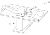
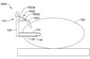
図1は、例示的な外科用システム100の一部分の斜視図である。手術台111(例えば、手術室内に位置する)上に腹臥位で横たわっている患者150が図1に例示されている。更に、患者150内の外科的標的部位への手術用通路を確立するために患者150の側方側に沿って位置付けられた外科用開創器アセンブリ112が、図1に例示されている。上述されたように、外科用開創器アセンブリ112は、患者150から外に側方に延在するため、重力が、外科用開創器アセンブリ112を患者150に対して意図せず調整させ、結果として、外科用開創器アセンブリ112によって作成された手術用通路の位置付けを調整させる様式で、外科用開創器アセンブリ112に作用する場合がある。1 is a perspective view of a portion of an exemplary
図2を参照すると、例示的な側方アクセス方法論の議論が提供される。患者150をうつ伏せにした状態(例えば、腹臥位)で、外科用開創器アセンブリ112の一部分は、切開部を通って腹膜後腔内に前進し、次いで、標的化された脊椎部位(例えば、一対の隣接する椎体間の椎間腔)に到達するまで腰筋を通って前進し得る。With reference to FIG. 2, a discussion of an exemplary lateral access methodology is provided. With the
いくつかの例では、拡張システム113が、患者150に挿入される外科用開創器システムの経路を確立するために利用され得る。拡張システム113は、最初の拡張器115と、直径が増加する1つ以上の追加の拡張器117とを有する順次拡張システム113を含み得る。いくつかの事例では、最初の拡張器115が、好ましくは、最初に標的部位まで前進し、次いで、増加する直径の追加の拡張器117の各々が、前の拡張器の上を覆うように順番に前進し得る。k-ワイヤ(図示せず)が、最初の拡張器115を標的部位に前進させる前、それと同時、又はその後に、標的部位まで前進し、定位置にドッキングされ得る(例えば、k-ワイヤを椎間板に挿入することによって)。順次拡張システム113が標的部位に隣接して位置付けられた(かつ任意選択的に、kワイヤを介して定位置にドッキングされた)状態で、開創器アセンブリ112は、次いで、順次拡張システム113の上を覆うように標的部位まで前進し得る。In some instances, the
示される例によると、外科用開創器アセンブリ112は、開創器ブレード114、116、118及び本体120を含み得る。いくつかの例では、開創器アセンブリ112は、中心開創器ブレード114が最後方ブレードであるように、拡張システム113の上を覆うように前進し得る。次いで、順次拡張システム113が除去され、開創器アセンブリ112が開かれて、手術用通路を拡張し得る。例えば、開創器ブレード114、116、及び118は、器具及びインプラントが標的部位まで前進し得る側方アクセス手術用通路を確立するように、互いに対して分離され得る(図1に例示されるように)。脊椎の外科的標的部位への略側方アプローチに関して本明細書で説明され示されているが(第1のブレード114が「後方」ブレードであり、第2のブレード116が「最頭蓋側」ブレードであり、第3のブレード118が「最尾側」ブレードである)、本発明の開創器アセンブリ112は、略後方、略後側方、略前方、及び略前側方を含む、任意の数の異なる外科的アプローチにおいて用途を見出し得ることが理解されるであろう。加えて、任意の数の処置が、側方アクセス通路を通して脊椎上で実施され得ることが理解されるであろう(例えば、外科医は、融合処置、全椎間板置換、椎体切除などを実施し得る)。According to the example shown, the
本明細書で論じられるように、いくつかの例では、外科用開創器アセンブリ112は、側方アクセス処置又は他の好適な処置中に利用されるときに、外科用開創器アセンブリ112に支持を提供するために、1つ以上の外科用開創器安定化システムと併せて使用され得る。例えば、1つ以上の外科用開創器安定化システムを介して、開創器ブレード114、116、118のうちの1つ以上は、開創器ブレード114、116、118を開いて手術用通路を確立する前に、脊椎に対する位置に固定され得る。As discussed herein, in some instances, the
いくつかの場合、1つ以上の開創器ブレード114、116、118を脊椎に対して定位置に固定することは、シム(例えば、安定器)を開創器ブレード114、116、118のうちの1つに取り付け、シムの遠位端を椎間腔内に挿入することによって達成され得る。例えば、開創器ブレード114、116、118の開放に続いて(又はその前に)、シム(一例では、後方開創器ブレード114と摺動可能に係合され得る)は、シムの遠位端領域が椎間腔の後方領域内に位置付けられるように前進し得る。ブレード114、116、118の後退前に、椎間腔の後方領域内にシムの遠位端領域を位置付けることは、他の開創器ブレード116、118が移動することができ、それによって、所望の又は調整可能なサイズの手術用通路を作成する場合であっても、後方開創器ブレード114が後退プロセス中に後方に、又は別様に移動しないことを確保するのを助け得る。In some cases, fixing one or
後方開創器ブレード114を固定することは、椎間腔に隣接する椎体に対して固定された関係で後方開創器ブレード114を堅固に結合し得る。加えて、椎体に対して固定された関係で後方開創器ブレード114を堅固に結合することは、概して、患者に対して前方(例えば、下向き)方向にアセンブリ112を引っ張るように作用する重力に対して、外科用開創器アセンブリ112を安定化させ得る。言い換えると、後方開創器ブレード114を脊椎の椎体に対して固定された関係で堅固に結合することは、臨床医がブレード114、116、118によって確立される手術用通路を通して1つ以上の器具を挿入しようとする際に、開創器アセンブリ112(開創器ブレード114、116、118を含む)が、ツール嵌入に応答して、下向きにシフトすること(例えば、垂下すること、落下すること、垂れること、下がることなど)、又は望ましくなく調整することを防止し得る。Fixing the
例えば、図3に図示されるようなシム200(例えば、安定器)は、側方アクセス処置中、外科用開創器アセンブリ112の位置を安定化することを容易にするために、外科用開創器アセンブリ112とともに使用され得る。例示的なシム200は、略硬質本体部分223、近位端領域227、及び遠位端領域228を含み得る。遠位端領域228は、脊椎の椎間腔内に挿入されるように設計された略テーパ形状を含み得る。加えて、シム200は、開創器ブレード114、116、118の内向き表面に沿った1つ以上の対応する溝(又は他の類似特徴)と係合することができるタブ要素224を含み得る。いくつかの例では、タブ要素224はまた、開創器ブレード114、116、118の内面に沿って提供された対応する溝内に係合する、拡大突出部を装備し得る。For example, a shim 200 (e.g., stabilizer) as illustrated in FIG. 3 may be used with the
図3に例示されるシム200は、第1の鋲部材225a及び第2の鋲部材225b(図3では隠れているが、図4に示されている)を含み得、それらの各々は、ピストン226に結合され得る。第1の鋲部材225a及び第2の鋲部材225bは、任意の好適な結合機構を用いてピストン226に結合され得る。一例では、ピン又は他の好適な結合機構が、第1の鋲部材225a及び第2の鋲部材225bを通って延在し、シム200の本体部分223内でピストン226に結合し得る。The
更に、ピストン226の作動は、図3を図4と比較するときに例示されるように、第1の鋲部材225a及び第2の鋲部材225bの各々を側方外向きに広げるように強制し得る。言い換えると、ピストン226を押し下げることは、第1の鋲部材225a及び第2の鋲部材225bを結合機構(例えば、ピン又は他の好適な結合機構)を中心として枢動させ、シム200内の位置から、椎間板又は隣接する椎骨との係合のために第1の鋲部材225a及び第2の鋲部材225bの各々の遠位端(例えば、遠位先端)が本体部分223の側縁から離れて延在して、シム200及び取り付けられた外科用開創器アセンブリ112を患者150の脊椎に対して固設する位置までシフトさせ得る。Furthermore, actuation of the
いくつかの場合、シム200は、図5に例示されるように、後方開創器ブレード114に結合され得る。シム200は、図5の後方開創器ブレード114に結合され、側方アプローチを使用する処置で開創器アセンブリ112を使用することを容易にし得るが、シム200は、開創器アセンブリ112の任意の追加の開創器ブレードに結合され得ることが企図される。使用時、シム200の遠位端領域228は、2つの隣接する椎体122の間に位置する椎間腔124内に位置付けられ得る。遠位端領域228が椎間腔124内に位置付けられると、ピストン226は、図5に例示されるように、シム200の遠位端領域228に向かって作動され得、それによって、第1の鋲部材225a及び第2の鋲部材225bの遠位端が椎体122のそれぞれ1つと係合するように、第1の鋲部材225a及び第2の鋲部材225bの各々を側方外向きに押す。椎体との第1の鋲部材225a及び第2の鋲部材225bの係合は、開創器アセンブリ112を椎体122に対して安定化させ得る。加えて、図5は、第1の鋲部材225a及び第2の鋲部材225bがピン接続229を介して結合され得ることを例示する。In some cases, the
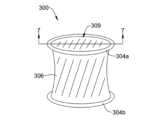
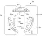
例示的な外科用開創器安定化システムの拡張可能な開創器300が図6に例示される。開創器300は、第1の支持リング304aと、第2の支持リング304b(例えば、第1の支持リング304aが位置付けられる端とは反対の端に位置付けられる)と、第1の支持リング304aと第2の支持リング304bとの間に延在する拡張可能な円筒形本体部分306と、を含み得る。拡張可能な開創器300は、収縮構成から拡張構成に半径方向に拡張し得、それによって、1つ以上の外科用器具を通過させるために利用され得る開口部309(例えば、トンネル、通路、手術用通路)を画定する。An exemplary
開創器300の拡張可能な本体部分306は、可撓性ポリマー膜、ワイヤメッシュ構造、組み合わせポリマー-ワイヤ構造から、又は半硬質円筒形構造と収縮構成との間でシフトすることができる任意の他の好適な材料から形成され得る。第1の支持リング304a及び第2の支持リング304bの各々は、少なくとも半硬質ポリマーリングであり得るか、又はそれを含み得る。本体部分306、第1の支持リング304a、及び第2の支持リング304bの各々は、収縮構成と拡張構成(図6に例示されるものなど)との間でシフトすることができ得る。加えて、拡張構成では、開創器300は、患者の皮膚を開創するために十分な半径方向強度を含み得、それによって、外科的標的部位への手術用通路を維持する。The
図7は、図6の線7-7に沿った開創器300の断面図を例示する。図7は、拡張構成にある開創器300を例示する。本明細書に説明されるように、図7は、第1の支持リング304aと第2の支持リング304bとの間に延在する拡張可能な本体部分306を例示する。FIG. 7 illustrates a cross-sectional view of the
拡張可能な開創器300が、図8に断面で図示されており、患者の腹壁303を横断して位置付けられている。拡張可能開創器300は、患者の腹壁303を開創し得、それによって、外科用開創器アセンブリ112の開創器ブレード(例えば、後方開創器ブレード114又は他の好適な開創器ブレード)が開創器300の開口部309を通して延在することを可能にする。The
いくつかの例では、外科用開創器アセンブリ112、拡張可能な開創器330は、図8及び図9に図示されるように、開創器安定化システムとともに、又はその一部として利用され得る。一例では、図8に図示される外科用開創器アセンブリ112は、外科用開創器アセンブリ112の1つ以上の他の特徴に結合され得る、1つ以上の係合部材(例えば、第1の係合部材310a及び第2の係合部材310b)を含み得る。例えば、図8に図示される第1及び第2の係合部材310a、310bは、開創器本体120又は1つ以上の開創器ブレード114、116、118に結合(例えば、取り付け、係合など)され得る。図8は、開創器本体120に取り付けられた第1及び第2の係合部材310a/310bの各々を例示する。In some examples, the
加えて、第1及び第2の係合部材310a、310bの各々は、図8に図示されるように、拡張可能な開創器300の開口部309を通過し得る。拡張可能な開創器300の開口部309を通過した後、一例では、第1及び第2の係合部材310a、310bの各々は、第2の支持リング304bの上に折り重ねられて、第2の支持リング304bと係合し得る。第2の支持リング304bと係合するために折り重ねられたとき、第1及び第2の係合部材310a、310bは(開創器アセンブリ112の本体120へのそれらの取り付けを介して)、標的外科的部位に対して開創器アセンブリ112を安定化させ得る。Additionally, each of the first and
開創器アセンブリ112と併せて利用される開創器安定化システムの別の例が、図9に図示される。図9に例示される開創器安定化システムは、図8に関して説明された外科用安定化システムと形態及び機能が同様であり得る。例えば、図9は、患者の腹壁303を横断して位置付けられた拡張可能な開創器300を例示する。拡張可能開創器300は、患者の腹壁303を開創し得、それによって、外科用開創器アセンブリ112の開創器ブレード114(例えば、近位開創器ブレード114)が開創器300の開口部309を通して延在することを可能にする。Another example of a retractor stabilization system utilized in conjunction with the
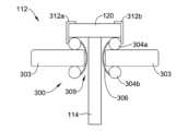
更に、図9に示される開創器安定化システムは、他の構成要素の中でもとりわけ、開創器アセンブリ112の本体120に結合され、かつ開創器300の第1の支持リング308aに解放可能に結合される、第1及び第2の係合部材312a、312bを含み得る。図8の開創器安定化システムの第1及び第2の係合部材310a、310bとは異なり、第1及び第2の係合部材312a、312bは、開創器300の開口部309を通って延在するように構成されなくてもよい。むしろ、第1及び第2の係合部材312a、312bは、患者の外側に位置付けられ得る。いくつかの例では、第1及び第2の係合部材312a、312bは、「L」字形を含み得、それによって、第1及び第2の係合部材312a、312bの一方の側は、開創器アセンブリ112の本体120に取り付けられ、第1及び第2の係合部材312a、312bの他方の側は、開創器300の第1の取り付け支持リング308aに取り付けられる(例えば、クリップ又は他の好適な結合機構)。開創器アセンブリ112の本体120及び第1の取り付け支持リング308aの両方に取り付けられたとき、第1及び第2の係合部材312a、312bは、標的外科的部位に対して開創器アセンブリ112を安定化させ得る。9 may include, among other components, first and
開創器アセンブリ(例えば、本明細書に説明される開創器アセンブリ112又は他の好適な開創器アセンブリ)と併せて利用され得る、例示的なシム400(例えば、安定器)の正面図が、図10Aに例示される。シム400は、略硬質本体部分423、近位端領域427、及び遠位端領域428を含み得る。遠位端領域428は、脊椎の隣接する椎骨間の椎間腔内に挿入されるように設計された略テーパ形状を含み得る。いくつかの場合、シム400は、開創器アセンブリ112の開創器ブレード114、116、118のうちの1つ以上の内向き表面に沿った1つ以上の対応する溝(又は他の同様の特徴)と係合することができる、タブ要素424(図3に関して説明されるタブ要素224と同様)を含み得る。いくつかの例では、タブ部材424はまた、開創器ブレード114、116、118の内面に沿って提供された対応する溝内に係合する、拡大突出部を装備し得る。A front view of an exemplary shim 400 (e.g., a stabilizer) that may be utilized in conjunction with a retractor assembly (e.g.,
図10Aに図示されるシム400は、接続部材425を介してシム400に結合された管状部材426を更に含み得る。接続部材425は、図10Bに図示されるように、シム400の前面と管状部材426との間に位置付けられ得る。加えて、図10A及び図10Bに図示される管状部材426は、シム400の近位端領域427から遠位端領域428まで延在し得る。いくつかの場合、管状部材426は、Kワイヤが通って延在し得る管腔429を含み得る。本明細書で論じられるように、kワイヤ(図示せず)は、事前拡張ステップ(例えば、手術用通路を確立するために開創器ブレード114、116、118の完全後退に先立って挿入部位が拡張される事前拡張ステップ)中に、標的部位まで前進し、定位置にドッキングされ得る(例えば、kワイヤを椎間板に挿入することによって)。いくつかの事例では、kワイヤは、椎間板終板を通して椎体内に挿入され得る。図3に図示されるシムに関して説明されたものと同様に、標的組織部位に隣接する椎体とのシム400の係合が、椎体に対して開創器アセンブリ112を安定化させ得る。The
図10A及び図10Bに例示されるものなどの、いくつかの例では、シム400、接続部材425、及び管状部材426は、単一のモノリシック構造として構築され得る。しかしながら、他の例では、接続部材425は、後でシム400に取り付けられ得る別個の構造として形成され得る。いくつかの事例では、接続部材425及び管状部材426は、シム400に後で取り付けられる(例えば、スナップフィットなど)モノリシック構成要素として形成され得る。In some examples, such as those illustrated in Figures 10A and 10B, the
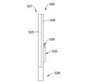
開創器アセンブリ(本明細書に説明される開創器アセンブリ112又は他の好適な開創器アセンブリなどの)と併せて利用され得る、別の例示的なシム500(例えば、安定器)の正面図が、図11Aに図示される。シム500は、略硬質本体部分523、近位端領域527、及び遠位端領域528を含み得る。遠位端領域528は、脊椎の隣接する椎体間の椎間腔内に挿入されるように設計された略テーパ形状を含み得る。A front view of another exemplary shim 500 (e.g., a stabilizer) that may be utilized in conjunction with a retractor assembly (such as
シム500の背面図が図11Bに図示されている。図11Bに図示されるように、シム500は、開創器アセンブリ112の開創器ブレード114、116、118の内向き表面に沿った1つ以上の対応する溝(又は他の同様の特徴)と係合することができる、タブ要素524(図3に関して説明されるタブ要素224と同様)を含み得る。いくつかの例では、タブ要素524はまた、開創器ブレード114、116、118の内面に沿って提供された対応する溝内に係合する、拡大突出部を装備し得る。A rear view of the
シム500の側面図が図11C及び図11Dに図示されている。シム500は、図11C及び図11Dに図示されるように、2部品シムとして構築され得、それによって、シム500は、第1の部品525及び第2の部品526を含み、第2の部品526は、第1の部品525上に配設されている。A side view of the
いくつかの例では、第1の部品525及び第2の部品526は、同じ材料から形成され得る。他の例では、第1の部品525及び第2の部品526は、異なる材料から形成され得る。In some examples, the
シム500は、図11C及び図11Dに図示されるように、シム500を一方の側から反対側に斜めに横断して延在する管腔529(例えば、開口、開口部、トンネル、通路、チャネルなど)を含み得る。管腔529の第1の側面開口部が図11Cに図示され、管腔の第2の側面開口部が図11Dに図示されており、管腔529は、第1の側面から第2の(反対の)側面まで連続的に延在し得るが、これは必須ではない。いくつかの例では、管腔529は、第2の部品526の隆起部分530を貫通して形成され得る(例えば、図11C及び図11Dに図示されるように)。言い換えると、シム500は、シム500を斜めに横断して延在する隆起部分530を含み得、それによって、管腔529は、シム500を斜めに横断する隆起部分530を通って延在する。The
更に、kワイヤ(図示せず)は、事前拡張ステップ(例えば、手術用通路を確立するために開創器ブレード114、116、118の完全後退に先立って挿入部位が拡張される事前拡張ステップ)中に、管腔529を通って標的部位まで前進し、定位置にドッキングされ得る(例えば、kワイヤを椎間板又は1つ以上の隣接する椎体内に挿入することによって)。図3のシムに関して説明されたものと同様に、隣接する椎体と標的組織部位に近位の隣接する椎体のうちの一方又は両方を伴うkワイヤとの間の椎間板とのシム500の係合が、椎体に対して開創器アセンブリ112を安定化させ得る。Additionally, a k-wire (not shown) may be advanced through
例示的な開創器安定化システム600が図12に図示されている。例示的な開創器ブレード614、616、618は、図12において断面で図示され、それによって、開創器ブレード614、616、618は、図1に示される開創器ブレード114、116、118と形態及び機能が類似し得る。言い換えると、図12は、標的外科的部位への手術用通路610を画定するために開放構成にある開創器ブレード614、616、618の断面図を例示する。An exemplary
更に、図12は、開創器ブレード614、616、618の各々が、開創器ブレード614、616、618の内面に沿って延在する1つ以上のチャネルを含み得ることを例示する。例えば、後方開創器ブレード614は、開創器ブレード614の内面に沿って延在する2つのチャネル622aを含み得、開創器ブレード616は、開創器ブレード616の内面に沿って延在する2つのチャネル622bを含み得、開創器ブレード618は、開創器ブレード618の内面に沿って延在する2つのチャネル622cを含み得るが、これは必須ではなく、他の好適な構成が企図される。いくつかの場合、チャネル622a、622b、622cは、それぞれ、開創器ブレード614、616、618の近位端領域から、それぞれ、開創器ブレード614、616、618の遠位端領域まで延在し得る。12 further illustrates that each of the
図12に図示されるチャネル622a、622b、622cは、安定化ピンがチャネル622a、622b、622cに沿って挿入されることを可能にし得、それによって、安定化ピンは、開創器ブレード614、616、618のうちの1つ以上を椎体122に固設し得る。例えば、安定化ピン620は、図12に図示されるように、後方開創器ブレード614のチャネル622aの各々の中に配設され得る。チャネル622aは、安定化ピン620がチャネル622a内で長手方向に摺動し得るように設計され得るが、チャネル622aは、安定化ピン620がチャネル622aから摺動して外れて、開創器ブレード614の内面から離れることを防止するように設計され得る。いくつかの場合、開創器ブレード616のチャネル622b及び開創器ブレード618のチャネル622cは、その中に挿入される安定化ピンが縦方向に摺動することを可能にするが、安定化ピンが開創器ブレードの内面から離れてチャネルから摺動して外れることを防止するように、同様に設計され得る。The
いくつかの場合、椎体122内に挿入されたとき、安定化ピン620は、標的外科的部位に対して近位開創器ブレード614及び開創器アセンブリ612を安定化させ得る。チャネルは、安定化ピン620がチャネル622a内で長手方向に摺動することを可能にするが、一方で、安定化ピン620が近位開創器ブレード614の内面から離れてチャネル622aから摺動して外れることも防止するように設計され得るため、安定化ピン620は、椎体122にねじ込まれ、側方アプローチを利用する処置中又は他の好適な処置中に、標的外科的部位に対して後方開創器ブレード614及び開創器アセンブリ612を安定化させ得る。後方開創器ブレード614は、図12では、その中に挿入される2つの安定化ピン620を有するが、開創器ブレード116、118のうちのいずれかは、チャネル622b、622c内に配設された(それによって、椎体122に固定される)1つ以上の安定化ピンを含み得ることが企図される。In some cases, when inserted into the
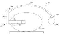
開創器アセンブリ112と併せて利用され得る、別の例示的な開創器安定化システムが、図13に図示される。例示的なカウンタウエイトシステム700が図13に図示されている。カウンタウエイトシステム700は、開創器アセンブリ112の本体120に取り付けられた近位端と、カウンタウエイト708に取り付けられた遠位端706とを有するアーム702を含み得る。本明細書で論じられるように、開創器ブレード114、116、118は、図13に図示されるように、患者150(概略的に図示されている)内に挿入されて、手術用通路を確立し得る。Another exemplary retractor stabilization system that may be utilized in conjunction with the
図13は、アーム702が、開創器アセンブリ112の本体120から、患者150の身体の上に、かつそれを横断して延在し得る(例えば、アームは、患者150の上に弧を描き得る)ことを更に例示する。アーム702は、開創器アセンブリ112に加わる下向きの重力をオフセットするためのレバーアームとして作用し得ることが理解され得る。カウンタウエイト708の比重は、開創器アセンブリ112の質量によって少なくとも部分的に生成される下向きの力を相殺するように設計され得る。いくつかの例では、カウンタウエイト708及びアーム702の屈曲部は、開創器アセンブリ112(開創器ブレード114、116、118を含む)が略固定位置で安定化されるように、開創器アセンブリ112に加わる下向きの重力をオフセットするように設計され得る。他の例では、カウンタウエイト708は、別の支持構造体に取り付けられずに自由に吊り下げられ得る。更に他の例では、カウンタウエイトは、手術室の固定された構成要素(例えば、手術台、壁、レール、ポールなど)に取り付けられるように設計され得る。13 further illustrates that the
例示的な開創器安定化システム800が図14に図示されている。例示的な開創器ブレード814、816、818の断面図が、図14に図示され、それによって、開創器ブレード814、816、818は、図1に示される開創器ブレード114、116、118と形態及び機能が類似し得る。図14に図示される開創器ブレード814、816、818は、標的外科的部位への手術用通路810を画定するように、開放構成にある。An exemplary
開創器ブレード814、816、818の各々は、図14に図示されるように、それぞれ、開創器ブレード814、816、818の各々の内面に取り付けられたベース部材820a、820b、820cを含み得る。加えて、開創器ブレード814、816、818の各々は、アーム822a、822b、822cを更に含み得、各アーム822a、822b、822cは、それぞれのベース部材820a、820b、820cから延在する近位端と、安定化ねじ824a、824b、824cを受容又はそれに結合される遠位端とを有する。安定化ねじ824a、824b、824cの各々は、患者の椎体122にねじ込まれ、それによって、開創器ブレード814、816、818のうちの1つ以上を椎体122に固定的に固設するように設計され得る。Each of the
椎体122内に挿入されたとき、安定化ねじ824a、824b、824cのうちの1つ以上は、安定化ねじ824a、824b、824cが結合される開創器ブレード814、816、818を安定化させ得る。それぞれの開創器ブレード814、816、818と結合された安定化ねじ824a、824b、824cは、開創器アセンブリ812(開創器ブレード814、816、818を含む)が略固定位置で安定化され得るように、開創器アセンブリ812に加わる下向きの重力をオフセットするように設計され得る。When inserted into the
開創器アセンブリ112と併せて利用され得る、例示的な開創器安定化システム900が、図15A及び図15Bに図示される。開創器アセンブリ112(開創器ブレード114、116、118及び本体120を含む)は、深度ラックアセンブリ910に結合され得る。深度ラックアセンブリ910は、患者に対する開創器アセンブリ112の位置を操作するように設計され得る。例えば、深度ラックアセンブリ910は、開創器アセンブリ112が患者の挿入部位内に前進すること、又はそこから引き抜かれることを可能にするように設計され得る。更に、本明細書で論じられるように、開創器ブレード114、116、118は、患者内の標的外科的部位への手術用通路を確立するために利用され得る。深度ラックアセンブリ910は、手術用通路を確立するときに、開創器ブレード114、116、118の設置を補助するように機能し得る。An exemplary retractor stabilization system 900 that may be utilized in conjunction with the
深度ラックアセンブリ910は、図15Aに図示されるように、第1のアーム902(例えば、関節運動アーム又は他の好適なアーム)を含み得る。第1のアーム902は、手術室の固定された構成要素912(例えば、手術台、壁など)に取り付けられるように設計された第1の端を含み得る。深度ラックアセンブリ910はまた、1つ以上の伸縮部材(例えば、伸縮アーム、ビームなどの、第1の伸縮部材906a及び第2の伸縮部材906b)を含み得る。第1及び第2の伸縮部材906a、906bは、互いに対して延在及び後退するように設計され得る。例えば、第1及び第2の伸縮部材906a、906bは、互いの相対移動に応答して、組み合わせられた長さを延長及び短縮するように設計され得る。加えて、深度ラックアセンブリ910は、コネクタ904を含み得る。更に、第1及び第2の伸縮部材906a、906bの各々は、コネクタ904内に少なくとも部分的に収容されるか、又はそれを通って延在し得る。第1及び第2の伸縮部材906a、906bのうちの一方は、コネクタ904内に収容されている間、他方の第1及び第2の伸縮部材906a、906b内に入れ子になってもよい。The
第1及び第2の伸縮部材906a、906bの操作は、患者の挿入部位に対して開創器アセンブリ112を前進又は後退させるために利用され得る。いくつかの例では、第1及び第2の伸縮部材906a、906b、並びにコネクタ904は、一緒に、患者の挿入部位に対して開創器アセンブリ112を前進、後退、又は維持するように設計される、システム、機構、アセンブリなどを全体的に又は少なくとも部分的に画定し得る。例えば、第2の伸縮部材906bは、開創器アセンブリ112を患者に向かって押し得る力を第1の伸縮部材906aに及ぼすように設計されたばねを含み得る。更に、いくつかの例では、コネクタ904は、ラチェットアセンブリ又は他の好適な調整アセンブリを含み得る。ラチェットアセンブリ又は他の好適な調整アセンブリは、第1の伸縮部材906aを第2の伸縮部材906bに向かって後退させ、それによって、第2の伸縮部材906b内に位置付けられたばねが圧縮され得るように設計され得る。更に、コネクタ904内に位置付けられたラチェットアセンブリ又は他の好適な調整アセンブリは、第1の伸縮部材906aが段階的に解放されることを可能にし得、それによって、第1の伸縮部材906aを解放することは、ばねの拡張及び制御された様式における患者に向かう第1の伸縮部材906aの前進を可能にする。第1の伸縮部材906aが第2の伸縮部材906bに対して所望の場所にあるとき、ラチェットアセンブリ又は他の好適な調整アセンブリは、第1の伸縮部材906aを所望の場所に解放可能に維持し得る。Manipulation of the first and second
いくつかの例では、ラックアセンブリ910は、図15Bに図示されるように、ラック部材904及び第1のアーム902に対して開創器アセンブリ112を側方にオフセットするように設計された第2のアーム906を更に含み得る。第2のアーム906は、伸縮部材906a、906bのうちの1つに結合された第1の端を含み得、開創器アセンブリ112の本体120に結合された第2の端も含み得る。In some examples, the
深度ラックアセンブリ910は、開創器アセンブリ112(開創器ブレード114、116、118を含む)が略固定位置で安定化され得るように、開創器アセンブリ112に加わる下向きの重力をオフセットするように設計され得る。図示されていないが、深度ラックアセンブリ910は、開創器アセンブリ112に対する構成で深度ラックアセンブリ910を固設するための1つ以上の係止構成要素を含み得る。The
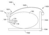
開創器アセンブリ112と併せて利用され得る、例示的な開創器安定化システム1000が、図16に図示される。図16は、手術用通路を確立するために患者150に挿入された開創器ブレード114、116、118を更に例示する。An exemplary
安定化システム1000は、開創器アセンブリ112の本体120に取り付けられた第1の端1021と、支持部材1024に取り付けられた第2の端1023とを有するストラップ1020を含み得る。いくつかの例では、支持部材1024は、それに取り付けられたボルスタを含み得る。加えて、いくつかの例では、支持部材1024は、支持部材1024を手術室の固定された構成要素1022に結合するように設計された解放可能な取り付け部材1026(例えば、クランプ、フック、ブラケット、留め金など)を含み得る。例えば、支持部材1024は、図16に図示されるように、患者150が位置付けられる台(例えば、固定された構成要素1022)に結合され得るクランプ(例えば、取り付け部材1026)を含み得る。The
図16は、ストラップ1020が、開創器アセンブリ112の本体120から、患者150の身体の上及びそれを横断して延在し得ることを更に例示する。支持部材1024に結合されたストラップ(例えば、ストラップの屈曲部)は、開創器アセンブリ112上に加えられた下向きの重力を相殺し得ることが理解され得る。いくつかの場合、ストラップ1020は、開創器アセンブリ112(開創器ブレード114、116、118を含む)が略固定位置で安定化され得るように、開創器アセンブリ112に加わる下向きの重力をオフセットするように設計され得る。16 further illustrates that the
いくつかの例では、ストラップ1020の第2の端1023は、取り付け部材1026に結合しなくてもよく、むしろ、ストラップ1020の第2の端1023は、患者150の胴体の周囲に巻き付き、開創器アセンブリ112の本体120に結合するように、又は代替的に、ストラップ1020の第1の端1021に結合するように構成され得る。ストラップ1020は、開創器アセンブリ112に加わる下向きの重力を相殺する適切な力を提供するように張力を加えられ得る。In some examples, the
更に他の例では、ストラップ1020の第2の端1023は、取り付け部材1026に結合されなくてもよく、むしろ、ストラップ1020の第2の端1023は、開創器アセンブリ112の質量によって少なくとも部分的に生成される下向きの力を相殺するように構成されたカウンタウエイトに結合され得る。ストラップ1020は、開創器アセンブリ112(開創器ブレード114、116、118を含む)が略固定位置で安定化され得るように、開創器アセンブリ112に加わる下向きの重力をオフセットするように設計され得る。In yet another example, the
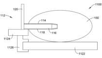
開創器アセンブリ112と併せて利用され得る、例示的な開創器安定化システム1100が、図17に図示される。開創器ブレード114、116、118は、図17に図示され、本明細書に論じられるように、患者150内に挿入されて、手術用通路を確立し得る。An exemplary
安定化システム1100は、その上に開創器アセンブリ112を支持するように設計されたプラットフォーム1124(例えば、台、スタンド、足場など)を含み得る。例えば、図17は、開創器ブレード114、116、118が患者150に挿入されて手術用通路を確立する間に、プラットフォーム1124上にある開創器アセンブリ112を示す。いくつかの例では、プラットフォーム1124は、プラットフォーム1124を手術室の固定された構成要素1122に結合するように設計された解放可能な取り付け部材1126(例えば、クランプ、フック、ブラケット、留め金など)に結合され得る。例えば、図17は、患者150が位置付けられる台(例えば、固定された構成要素1122)に結合されるクランプ(例えば、取り付け部材1126)にプラットフォーム1124が結合したことを例示する。プラットフォーム1124は、開創器アセンブリ112(開創器ブレード114、116、118を含む)が略固定位置で安定化され得るように、開創器アセンブリ112に加わる下向きの重力をオフセットするように設計され得る。The
開創器アセンブリ112と併せて利用され得る、例示的な開創器安定化システム1200が、図18に図示される。開創器ブレード114は、図18に図示されるように、患者150内に挿入されて、手術用通路を確立し得る。いくつかの場合、開創器安定化システム1200は、開創器本体120に結合される(例えば、取り付けられる、係合されるなど)第1の端と、患者の椎体122と係合するように設計された第2の端1224とを有するテザー部材1220を含み得る。An exemplary
いくつかの場合、テザー部材1220は、患者の皮膚(例えば、腹壁1203)を横断して延在し得、それによって、第2の端1224は、患者の椎体122と係合(例えば、その中にアンカー固定)し得る。本明細書でより詳細に説明されるように、テザー部材1220の第2の端1224は、椎体122と係合する(例えば、その中にアンカー固定する)ように設計されたアンカー部材1226を含み得る。In some cases, the
いくつかの例では、テザー部材1220は、テザー部材1220が開創器本体120及び椎体122の両方に結合されたときに、テザー部材1220が張力下に置かれることを可能にする材料から形成され得る。開創器本体120及び椎体122の両方に結合されたとき、テザー部材1220は、開創器アセンブリ112(開創器ブレード114、116、118を含む)が略固定位置で安定化されるように、開創器アセンブリ112に加わる下向きの重力をオフセットするように設計され得る。In some examples, the
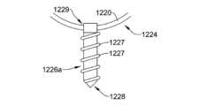
テザー部材1220とともに利用され得る例示的なアンカー部材1226aが、図19に図示される。アンカー部材1226aは、テザー部材1220の第2の端に結合され得る。更に、アンカー部材1226aは、図19に図示されるように、概して尖った形状を有する遠位端1228を含み得る。加えて、アンカー部材1226aは、アンカーが椎体122に「ねじ込まれる」ことを可能にするように設計された1つ以上のねじ山1227を含み得る。加えて、アンカー部材1226aは、ハトメ1229を含み得、ハトメ1229は、テザー部材1220の第2の端1224がハトメ1229を通って延在することを可能にするように設計されている。An
テザー部材1220とともに利用され得る別の例示的なアンカー部材1226bが、図20に図示される。アンカー部材1226bは、テザー部材1220の第2の端1224に結合され得る。図20は、アンカー部材1226bが、椎体122を貫通するように設計された1つ以上のプロング1233を含む遠位端1232を含み得ることを例示する。いくつかの例では、プロング1233は、椎体122内に下穴を形成し得る。Another
アンカー部材1226bは、椎体122を貫通してその中にアンカー固定するように設計された1つ以上の拡張アーム1230a、1230bを含み得る。1つ以上の拡張アーム1230a、1230bは、1つ以上の拡張アーム1230a、1230bがアンカー部材1226bの長手方向軸に略平行である(患者への挿入のために)第1の構成(例えば、送達構成)、及び1つ以上の拡張アーム1230a、1230bが椎体122と係合するように延在される第2の構成からシフトするように設計され得る。The
あるいは、1つ以上の拡張アーム1230a、1230bは、2つの隣接する椎体122間の椎間腔内にアンカー部材1226の締まり嵌めを提供するように設計され得る。1つ以上の拡張アーム1230a、1230bは、1つ以上の拡張アーム1230a、1230bがアンカー部材1226bの長手方向軸に略平行である(患者への挿入のために)第1の構成(例えば、送達構成)、及び1つ以上の拡張アーム1230a、1230bが椎体122間の椎間腔内で締まり嵌めを提供するように延在される第2の構成からシフトするように設計され得る。加えて、アンカー部材1226bは、ハトメ1234を含み得、ハトメ1234は、テザー部材1220の第2の端1224がハトメ1234を通って延在することを可能にするように設計されている。Alternatively, one or
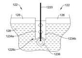
テザー部材1220とともに利用され得る別の例示的なアンカー部材1226cが、図21及び図22に図示される。図21に図示されるアンカー部材1226cは、テザー部材1220の第2の端1224に結合された遠位ハトメ1236を含み得る。加えて、アンカー部材1226cは、図21に図示されるように、第1の拡張可能アーム1234a及び第2の拡張可能アーム1234bを更に含み得る。いくつかの場合、テザー部材1220は、第1の拡張可能なアーム1234aと第2の拡張可能なアーム1234bとの間を通過し得る。Another
図21に図示されるアンカー部材1226cは、第1の構成にあり、それによって、アンカー部材1226cは、椎体122の緻密骨126に形成された穴を通して挿入された後、椎体122の海綿骨128内に位置付けられる。第1の構成では、第1の拡張可能なアーム1234a及び第2の拡張可能なアーム1234bは、後退位置にある(例えば、拡張されていない)。The
図22に図示されるアンカー部材1126cは、第2の構成にあり、それによって、アンカー部材1226cは、椎体122の緻密骨126に形成された穴を通して挿入された後、椎体122の海綿骨128内に位置付けられる。図22に図示されるハトメ1236は、第1の拡張可能なアーム1234aと第2の拡張可能なアーム1234bとの間で後退しており、それによって、ハトメ1236の後退は、第1の拡張可能なアーム1234a及び第2の拡張可能なアーム1234bを外向きに拡張させる(例えば、第1の拡張可能なアーム1234a及び第2の拡張可能なアーム1234bは、テザー部材1220から離れて側方外向きに駆動される)。第1の拡張可能なアーム1234a及び第2の拡張可能なアーム1234bの拡張は、図22に図示されるように、アンカー部材1226cが椎体122を通って後退して戻ることを防止し得る。The anchor member 1126c illustrated in FIG. 22 is in a second configuration whereby the
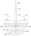
例示的なアンカーシステム1326が図23に図示されている。アンカーシステム1326は、椎体122の緻密骨126に形成された穴を通して挿入された後、椎体122の海綿骨128内に位置付けられる。アンカーシステム1326は、テザー部材1320の遠位端に結合された遠位ハトメ1336を含み得る。いくつかの例では、図23に示されるテザー部材1320は、ワイヤを含み得る。図23に図示されるアンカーシステム1326は、カニューレ1342の遠位端に沿って配設された第1の拡張可能なアーム1334a及び第2の拡張可能なアーム1334bを含むカニューレ1342を更に含み得る。いくつかの場合、カニューレ1342は、テザー部材1320がその中に延在することを可能にする管腔を含み得る。したがって、テザー部材1320は、カニューレ1342の管腔内で並進し得る。An
カニューレ1342は、外側カニューレ1340の管腔内に延在し得、カニューレ1342は、外側カニューレ1340の管腔内で並進し得る。いくつかの例では、外側カニューレ1340は、シムに結合され得るが、これは必須ではない。加えて、本明細書に説明されるアンカー部材1226cと同様に、カニューレ1342の遠位端に沿って配設される第1の拡張可能なアーム1334a及び第2の拡張可能なアーム1334bは、椎体122に隣接して位置付けられ得る。The
テザー部材1320は、図23に図示されるように、第1の拡張可能なアーム1334aと第2の拡張可能なアーム1334bとの間を通過し得る。本明細書に説明されるアンカー部材1226cと同様に、ハトメ1336は、第1の拡張可能なアーム1334aと第2の拡張可能なアーム1334bとの間で後退しており、それによって、ハトメ1336の後退は、第1の拡張可能なアーム1334a及び第2の拡張可能なアーム1334bを外向きに拡張させる(例えば、第1の拡張可能なアーム1334a及び第2の拡張可能なアーム1334bは、テザー部材1320から離れて側方外向きに駆動される)。第1の拡張可能なアーム1334a及び第2の拡張可能なアーム1334bの拡張は、アンカーシステム1326が椎体122を通して後退して戻ることを防止し得ることが理解され得る。23. The
開創器アセンブリ112と併せて利用され得る、例示的な開創器安定化システム1400が、図24に図示される。本明細書で論じられるように、開創器アセンブリ112は、患者150内への手術用通路を確立するために利用される。An exemplary
安定化システム1400は、開創器アセンブリ112の本体120に結合された第1の端1421と、支持アーム1424に結合された第2の端1423とを有する支持部材1420(例えば、ロープ、ワイヤ、チェーンなど)を含み得る。更に、いくつかの例では、支持アーム1424は、支持アーム1424を手術室の固定された構成要素1422に結合するように設計された解放可能な取り付け部材1426(例えば、クランプ、フック、ブラケット、留め金など)を含み得る。一例では、支持アーム1424は、図24に図示されるように、患者150が位置付けられる台(例えば、固定された構成要素1422)に結合されるクランプ(例えば、取り付け部材1426)を含み得る。いくつかの例では、支持アーム1424は、手術室の固定された構成要素1422に直接取り付けられ得る。例えば、支持アーム1424は、固定された構成要素1422に直接溶接され得る(又は任意の好適な取り付け技術を使用して取り付けられる)が、これは必須ではない。The
安定化システム1400は、開創器アセンブリ112が支持部材1420から吊り下がること、又は支持部材1420から引き上げられることを可能にし得る。したがって、安定化システム1400は、開創器アセンブリ112(開創器ブレード114、116、118を含む)が略固定位置で安定化され得るように、開創器アセンブリ112に加わる下向きの重力をオフセットするように設計され得る。The
開創器アセンブリ112と併せて利用され得る、例示的な開創器安定化システム1500が、図25に図示される。安定化システム1500は、他の好適な構成要素の中でもとりわけ、シム1510(例えば、安定器)を含み得る。シム1510は、略硬質本体部分1523、近位端領域1527、及び遠位端領域1528を含み得る。遠位端領域1528は、脊椎の椎間腔内に挿入されるように設計された略テーパ形状を含み得る。加えて、シム1510は、開創器ブレード114、116、118の内向き表面に沿った1つ以上の対応する溝(又は他の類似特徴)と係合することができるタブ要素1524を含み得る。いくつかの例では、タブ要素1524はまた、開創器ブレード114、116、118の内面に沿って提供された対応する溝内に係合する、拡大突出部を装備し得る。An exemplary
安定化システム1500は、連結アセンブリ1525aを介してシム1510に結合された第1の係合部材1522a及び第2の係合部材1522bを含み得る。加えて、安定化システム1500は、連結アセンブリ1525aに結合されたねじ1526を更に含み得る。ねじ1526の作動は、連結アセンブリ1525aを作動させ得、それによって、連結アセンブリ1525aの作動は、第1の係合部材1522a及び第2の係合部材1522bの各々を側方外向きに広げるように強制し得る。The
シム1510の遠位端領域1528は、図25に図示されるように、2つの隣接する椎体122の間に位置する椎間腔124内に位置付けられ得る。ねじ1526の作動は、第1の係合部材1522a及び第2の係合部材1522bの各々が椎体122のうちの1つと係合するように、第1の係合部材1522a(例えば、第1の鋲部材)及び第2の係合部材1522b(例えば、第2の鋲部材)の各々を側方外向きに強制し得る。椎体122との第1の係合部材1522a及び第2の係合部材1522bの係合は、椎体122に対して開創器アセンブリ112を安定化させ得る。The
開創器アセンブリ112と併せて利用され得る、開創器安定化システム1500の変形例が、図26に図示される。図26に示される安定化システム1500は、他の好適な構成要素の中でもとりわけ、シム1510を含み得る。シム1510は、略硬質本体部分1523、近位端領域1527、及び遠位端領域1528を含み得る。遠位端領域1528は、脊椎の椎間腔内に挿入されるように設計された略テーパ形状を含み得る。加えて、シム1510は、開創器ブレード114、116、118の内向き表面に沿った1つ以上の対応する溝(又は他の類似特徴)と係合することができるタブ要素1524(図26に示される)を含み得る。いくつかの例では、タブ要素1524はまた、開創器ブレード114、116、118の内面に沿って提供された対応する溝内に係合する、拡大突出部を装備し得る。A variation of a
図26に示される安定化システム1500は、連結アセンブリ1525bを介してシム1510に結合された第1の係合部材1522a及び第2の係合部材1522bを含み得る。加えて、図26に示される安定化システム1500は、シム1510に結合された楔1530を更に含み得る。楔1530は、連結アセンブリ1525bと整列され得る。楔1530は、それに結合された作動部材1532を含み得る。作動部材1532の作動は、楔1530を第1の係合部材1522aと第2の係合部材1522bとの間に向かって駆動するように設計され得、それによって、楔1530を第1の係合部材1522aと第2の係合部材1522bとの間に駆動することは、第1の係合部材1522a及び第2の係合部材1522bを側方外向きに広げ得る。The
シム1510の遠位端領域1528は、図26に図示されるように、2つの隣接する椎体122の間に位置する椎間腔124内に位置付けられ得る。第1の係合部材1522aと第2の係合部材1522bとの間に楔1530を駆動することは、第1の係合部材1522a及び第2の係合部材1522bの各々が椎体122のうちの1つと係合するように、第1の係合部材1522a(例えば、第1の鋲部材)及び第2の係合部材1522b(例えば、第2の鋲部材)の各々を側方外向きに強制し得る。椎体122との第1の係合部材1522a及び第2の係合部材1522bの係合は、椎体122に対して開創器アセンブリ112を安定化させ得る。The
開創器アセンブリ112と併せて利用され得る、例示的な開創器安定化システム1600が、図27に図示される。本明細書で論じられるように、開創器アセンブリ112は、患者150内への手術用通路を確立するために利用され得る。An exemplary
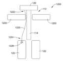
開創器安定化システム1600は、アンカーアセンブリ1620を含み得る。いくつかの事例では、アンカーアセンブリ1620は、第1の支持アーム1623a及び第2の支持アーム1623bを含み得る。第1の支持アーム1623a及び第2の支持アーム1623bの各々は、開創器アセンブリ112の本体120に取り付けられた第1の端を含み得る。加えて、第1の支持アーム1623a及び第2の支持アーム1623bの各々は、アンカーピン1621に取り付けられる第2の端を含み得る。The
いくつかの例では、アンカーピン1621は、第1の支持アーム1623a及び第2の支持アーム1623bの各々に対してある角度で延在し得る。加えて、アンカーピン1621は、患者150の骨にアンカー固定されるように設計され得る。一例では、アンカーピン1621は、患者150の寛骨にアンカー固定されるように設計され得るが、アンカーピン1621は、患者150の他の骨材料と係合するように構成され得る。患者150の骨とのアンカーピン1621の係合は、手術用通路に対して開創器アセンブリ112を安定化させ得る。加えて、アンカーピン1621は、脊椎内に既に位置付けられた後方固定ねじに係合するように設計され得る。In some examples, the anchor pin 1621 may extend at an angle relative to each of the
開創器アセンブリ112と併せて利用され得る、例示的な開創器安定化システム1700が、図28に図示される。安定化システム1700は、第1のシム1710(例えば、第1の安定器)を含み得る。第1のシム1710は、略硬質本体部分1723(例えば、シム本体)、近位端領域1727、及び遠位端領域1728を含み得る。遠位端領域1728は、脊椎の椎間腔124内に挿入されるように設計された略テーパ形状を含み得る。加えて、第1のシム1710は、開創器アセンブリブレード(例えば、開創器ブレード114、116、118のうちの1つ)の内向き表面に沿った1つ以上の対応する溝(又は他の類似特徴)と係合することができるタブ要素1724を含み得る。いくつかの例では、タブ要素1724はまた、開創器アセンブリ112の開創器ブレード114、116、118の内面に沿って提供された対応する溝内に係合する、拡大突出部を装備し得る。An exemplary
安定化システム1700は、第2のシム1720(例えば、第2の安定器)を含み得る。第2のシム1720は、開創器アセンブリ112の開創器ブレード114、116、118の内向き表面に沿って位置付けられた1つ以上の対応する溝と係合するように設計された取り付け領域1725を含み得る。加えて、第2のシム1720は、取り付け領域1725に結合されるオフセット部分1726を含み得る。第2のシム1720のオフセット部分1726は、第2のシム1720のオフセット部分1726を通って延在する管腔を含み得る。いくつかの例では、第2のシム1720の一部であってもよく、又はそうでなくてもよい取り付け構成要素1730(例えば、kワイヤ又は他の好適な取り付け構成要素)は、第2のシム1720のオフセット部分1726の管腔を通って延在し得る。取り付け構成要素1730は、事前拡張ステップ(例えば、手術用通路を確立するために開創器ブレード114、116、118の完全後退に先立って挿入部位が拡張される事前拡張ステップ)中に、標的部位まで前進し、定位置にドッキングされ得る(例えば、kワイヤを椎間板に挿入することによって)。標的組織部位に隣接する椎体122との第2のシム1720の係合(例えば、取り付け構成要素1730を介して)は、椎体に対して開創器アセンブリ112を安定化させ得る。The
開創器アセンブリ112を含むか、又はそれと併せて利用され得る、例示的な開創器安定化システム1800が、図29に図示される。開創器安定化システム1800は、対象に対して開創器アセンブリ112を安定化させることを容易にするために、対象(例えば、患者又は他の好適な対象)が腹臥位にあるときの脊椎処置において、又は対象が腹臥位又は他の体位にあるときの他の好適な処置において使用されるように構成され得る。開創器安定化システム1800が利用され得る1つの例示的な処置は、腰椎側方椎体間固定術(extreme lateral interbody fusion、XLIF)腹臥位処置であるが、開創器安定化システム1800は、他の好適な処置で利用され得る。追加的又は代替的に、開創器安定化システム1800は、限定されるものではないが、対象が非腹臥位にあるXLIF処置を含む、対象が腹臥位以外の体位(例えば、側臥位など)にある手術で利用され得る。An exemplary
開創器安定化システム1800は、対象の脊椎への手術用通路を確立するように構成された開創器アセンブリ112と、1つ以上のシムアセンブリ(例えば、1つ以上の安定器)と、を含み得る。1つ以上のシムアセンブリは、1つ以上のシム本体、1つ以上の取り付け構成要素、又はその両方を含み得る。1つの例示的な動作では、1つ以上のシム本体は、開創器アセンブリ(例えば、開創器アセンブリ112又は他の好適な開創器アセンブリ)の後方ブレード(例えば、後方ブレード114又は他の好適な後方ブレード)内に設置され得、取り付け構成要素は、シム本体を通して、後方ブレードの頭蓋側又は尾側で椎骨組織内に挿入され得る。追加的又は代替的に、1つ以上のシムアセンブリは、後方ブレード以外の1つ以上の開創器ブレードと係合され得る。取り付け構成要素は、開創器アセンブリと対象の椎体との間の固定を提供し、外科処置を通して、重力、器具嵌入などからの望ましくない開創器アセンブリ移動を防止又は緩和するように構成され得る。The
図29に図示される安定化システム1800は、第1のシムアセンブリ又はシム(例えば、第1の安定器)1810を含み得る。第1のシム1810は、開創器アセンブリに解放可能に結合し(例えば、開創器アセンブリ112のブレードに沿って摺動するか、又は1つ以上の他の好適な様式で開創器アセンブリに結合することによって)、開創器アセンブリが手術用通路を確立している間に対象の椎間板組織と係合するように構成され得る。第1のシム1810は、椎間板組織と係合するように構成される、本明細書で論じられるシムの特徴と同様の特徴又はそれらとは異なる特徴を有し得る。The
第1のシム1810は、略硬質本体部分1823(例えば、シム本体)、近位端領域1827、及び遠位端領域1828を含み得る。遠位端領域1828は、椎間腔124(例えば、脊椎の椎間板組織又は他の好適な椎間腔)内に挿入されるように設計された略テーパ形状を含み得る。更に、第1のシム1810は、開創器アセンブリブレード(例えば、開創器ブレード114、116、118のうちの1つ)の内向き表面に沿った1つ以上の対応する溝(又は他の類似特徴)と係合することができるタブ要素1824を含み得る。いくつかの例では、タブ要素1824はまた、開創器アセンブリ112の開創器ブレード114、116、118の内面に沿って提供された対応する溝内に係合する、拡大突出部を装備し得る。The
安定化システム1800は、第2のシムアセンブリ又は第2のシム1820(例えば、第2の安定器)を含み得る。第2のシム1820は、開創器アセンブリに解放可能に結合し(例えば、開創器アセンブリ112のブレードに沿って摺動するか、又は1つ以上の他の好適な様式で開創器アセンブリに結合することによって)、開創器アセンブリ112が手術用通路を確立している間、対象の椎骨組織と係合するように構成され得る。標的組織部位に隣接する椎体122との第2のシム1820の係合は、椎体に対して開創器アセンブリ112を安定化させるか、又は安定化させることを少なくとも容易にし得る。第2のシム1820は、開創器アセンブリ112と結合するように構成されたシム本体1832と、対象の椎骨組織と係合するように構成された取り付け構成要素1834と、を含み得る。The
第2のシム1820のシム本体1832は、開創器アセンブリ112の開創器ブレード114、116、118(例えば、後方開創器ブレード114又は他の好適な開創器ブレード)の内向き表面に沿って位置付けられた1つ以上の対応する溝と係合するように設計された取り付け領域1825を含み得る。いくつかの場合、シム本体1832の遠位端は、シム本体1832が開創器ブレード114、116、118に解放可能に結合される場所の遠位の場所で、開創器ブレード114、116、118に結合された第1のシム1810の近位端と係合するように構成され得る。加えて、第2のシム1820は、取り付け領域1825に結合されるか、又はそこから延在し得るオフセット部分1826を含み得る。The
いくつかの場合、オフセット部分1826は、取り付け構成要素1834を受容するためのガイド1830を含み得る。一例では、ガイド1830は、オフセット部分1826に位置付けられたとき、シム本体1832、シム本体1832が位置付けられる開創器ブレード、又はその両方の中心長手方向軸からオフセットされ得る。いくつかの場合、ガイド1830は、図29に示されるように、近位端及び遠位端を有し得、近位端がシム本体1832の遠位端の近位に位置し、ガイド1830の遠位端がシム本体1832の遠位端の遠位にある。In some cases, the offset
第2のシム1820の取り付け構成要素1834は、ガイド1830に解放可能に結合し、ガイド1830の管腔を通って延在するように構成され得る。ガイド1830は、第2のシム1820を受容する開創器アセンブリの開創器ブレードが対象内に手術/外科用通路を形成しているときに、取り付け構成要素1834の遠位端を対象の椎骨組織122に向けるように構成され得る。ガイド1830内に位置付けられたとき、取り付け構成要素1834は、ガイド1830を通って椎骨組織内に前進して、対象の椎骨組織に対して安定化システム1800及び開創器アセンブリ112を固設し得る。椎骨組織内の取り付け構成要素1834及び開創器アセンブリ112内の第2のシム1820のそのような位置付けは、開創器アセンブリ112が外科用通路(例えば、腹臥位の対象との側方外科用通路又は他の好適な外科用通路)を形成している間に、対象の脊椎の移動、重力、ツール嵌入力、又はそれらの組み合わせに対して開創器アセンブリ112を安定化させることを容易にし得る。The
手術において、第2のシム1820は、外科的部位で開創器アセンブリ112の後方ブレード114内に挿入され(例えば、その溝に沿って摺動され)、椎間板を第1のシム1810と係合させ得る。次いで、取り付け構成要素1834は、開創器ブレード114、116、118を拡張して手術用通路を外科処置を実施するのに望ましいサイズに拡張する前に、開創器アセンブリ112が対象の脊椎に対して固設され得るように、例えば、図30に図示されるように、事前拡張ステップ中に対象の椎骨組織内に前進し得る。In surgery, the
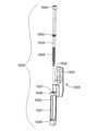
分解構成の第2のシム1820が図31に図示されている。上述されたように、第2のシム1820は、シム本体1832及び取り付け構成要素1834を含み得る。The
第2のシム1820のシム本体1832は、取り付け領域1825及びオフセット部分1826を含み得る。いくつかの場合、オフセット部分1826は、図31に図示されるように、取り付け領域1825から側方、長手方向、又は軸方向にオフセットされ得る。The
第2のシム1820のオフセット部分1826は、第2のシム1820のオフセット部分1826を通って延在する管腔を有するか、又はそれを画定するガイド1830であり得るか、又はそれを含み得る。ガイド1830の管腔は、ガイド1830の長さを通して完全に又は少なくとも部分的に延在するように構成され得る。The offset
いくつかの場合、ガイド1830は、1つ以上の部分を有し得る(例えば、ガイド1830は、連続的であるか、又は2つ以上の部分に分離され得る)。一例では、ガイド1830は、図31に図示されるように、第1の部分1836(例えば、近位部分)と、第1の部分1836から離隔された第2の部分1838(例えば、遠位部分)と、第1の部分1836と第2の部分1838との間に延在する中間部分1837と、を有し得る。In some cases, the
ガイド1830は、近位端及び遠位端を有する1つ以上のガイドチューブであり得るか、又はそれらを含み得る。ガイド1830が第1の部分1836及び第2の部分1838を含むとき、第1の部分1836及び第2の部分1838は、各々、取り付け構成要素1834を受容するように構成された管腔を画定する管であり得、第1の部分1836の管は、中間部分1837(例えば、開放又は非管状中間部分によって第2の部分1838の管に接続され得る。いくつかの場合、第1及び第2の部分1836、1838又は他の管状部分は、完全な円形断面又は管腔を有していない部分的な管であり得る。The
ガイド1830の管腔は、取り付け構成要素1834を受容するように任意の好適な様式で構成される。必須ではないが、ガイド1830の管腔は、取り付け構成要素1834がガイド1830内又はそれを通って挿入される際に、ガイド1830に対して1つ以上の位置で取り付け構成要素1834を係合又は支持するように構成された1つ以上の特徴を有し得る。一例では、ガイド1830の第1の部分1836の管腔(例えば、ガイド1830の管の近位端に近接する)は、取り付け構成要素1834の第1の部分1842のねじ山又は表面と係合するように構成されたねじ山1837を含み得る。第1の部分1836と取り付け構成要素との間の結合は、第2のシムが後退アセンブリ112を用いて対象内に挿入される際に、取り付け構成要素1834の椎骨係合部分が、ガイド1830(例えば、第2の部分1838)によって完全に又は少なくとも部分的に覆われるように、ガイド1830に対して取り付け構成要素1834を固設する(例えば、装填位置又は他の好適な位置で)ように構成され得る。The lumen of the
ガイド1830の第2の部分1838における管腔は、任意の好適な様式で構成され得る。いくつかの場合、第2の部分1838は、ガイド1830の第1の部分1836が取り付け構成要素1834と係合する間に、第2の部分1838が取り付け構成要素1834の骨係合部分を完全に又は少なくとも部分的に覆うように、長さを有し得るか、又はガイド1830の第1の部分1836に対して位置付けられ得る。一例では、第2の部分1838は、ガイド1830の遠位端に近接して位置付けられ得、ガイド1830の第1の部分1836が取り付け構成要素1834と係合しているときに、取り付け構成要素1834の少なくとも遠位先端を覆って、取り付け構成要素1834の遠位先端が対象の身体組織と係合することなく、第2のシム1820を対象の体内に挿入することを容易にするように構成された長さを有し得る。The lumen in the
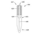
取り付け構成要素1834は、ガイド1830を通過して対象の椎骨組織に入る(例えば、椎骨組織の皮質/緻密骨、海綿骨、又は両方を通過する)ように構成された任意の好適なタイプの取り付け構成要素であり得る。例示的な好適な取り付け構成要素1834は、限定されるものではないが、kワイヤ、ねじ、及び/又は椎骨組織と係合してシム本体1832に結合するように構成された他の取り付け構成要素を含む。一例では、取り付け構成要素1834は、ねじとみなされ得、ねじ山を含み得る。The
いくつかの場合、取り付け構成要素1834は、ガイド1830を通って延在するように構成された任意の好適なサイズ及び形状であり得る。一例では、取り付け構成要素1834は、細長く、ガイド1830を通って延在するのに十分な長さを有し、椎骨組織からの取り付け構成要素1834の引き出しに抵抗するのに十分な深さの所定の距離だけ椎骨組織内に延在し、取り付け構成要素1834が椎骨組織内に所定の距離だけ挿入されたときに、ガイド1830の第1の部分1836の近位端と取り付け構成要素1834の近位ヘッド1840の遠位端との間に空間を作成し得る。In some cases, the
いくつかの場合、取り付け構成要素1834の近位ヘッド1840は、第1の外径を有し得、近位ヘッド1840から遠位に延在する取り付け構成要素の細長い部分は、細長い部分に沿った全ての又は少なくともいくつかの場所で第1の外径未満である第2の外径を有し得る。取り付け構成要素1834の第1の外径は、ガイド1830の近位における管腔の内径よりも大きくてもよく、取り付け構成要素1834の第2の外径は、ガイド1830の近位端における管腔の内径未満であり得る。そのような構成は、対象の椎骨組織内への取り付け構成要素1834の過剰挿入を防止することを容易にし得る。いくつかの場合、ガイド1830の近位端は、以下でより詳細に論じられるように、取り付け構成要素が椎骨組織と完全に係合している(例えば、所定の距離に挿入され、挿入位置にある)とき、近位ヘッド1840の遠位端(例えば、取り付け構成要素の第1の外径と第2の外径との間の移行部)から調整可能に離隔されるように構成され得る。In some cases, the
いくつかの場合、取り付け構成要素1834は、第1の部分1842(例えば、ガイド結合部分又は近位部分)及び第2の部分1844(例えば、椎骨結合部分又は遠位部分)を有し得る。取り付け構成要素1834の第1の部分1842は、ガイド1830の第1の部分1836と係合するように構成され得る。一例では、取り付け構成要素の第1の部分1842は、第2のシム1820又は後退アセンブリ112の挿入中に、ガイド1830の第1の部分1836のねじ山1837と係合して、取り付け構成要素1834をガイド1830及びシム本体1832に結合するように構成された第1のピッチ又は構成を有するねじ山を含み得る。In some cases, the mounting
取り付け構成要素1834の第2の部分1844は、対象の椎骨組織と解放可能に係合するように構成された第2のピッチ又は構成を有するねじ山を含み得る。第1の部分1842のねじ山の第1のピッチ及び第2の部分1844のねじ山の第2のピッチは、必要に応じて、同じピッチであってもよく、又は異なるピッチであってもよい。The
第2の部分1844のねじ山は、開創器アセンブリの引き出し又は意図しない移動(例えば、本明細書で論じられるように、好適な量の遊びを越える)を防止又は緩和しつつ、椎骨組織と係合し、取り付け構成要素1834を椎骨組織内に固設するための任意の好適な長さであり得る。いくつかの場合、第2の部分1844のねじ山は、取り付け構成要素1834の遠位先端から任意の好適な距離だけ近位に延在し得る。好適な距離の例としては、限定されるものではないが、最大で、取り付け構成要素1834が挿入される椎骨の幅、0.5インチ~2.25インチの長さ、及び/又は他の好適な距離までを含む。一例では、取り付け構成要素1834の遠位先端から近位に延在するねじ山の長さ又は距離は、1.0インチであってもよく、又は約1.0インチであってもよいが、これは必須ではなく、長さ又は距離は、1.0インチより短くてもよく、又はそれよりも長くてもよい。The threads of the
取り付け構成要素1834のねじ山は、連続していてもよく、又は互いに離隔されていてもよい。一例では、第2の部分1844のねじ山は、図31に図示されるように、第1の部分1842のねじ山から遠位に(例えば、取り付け構成要素1834の遠位端に、又はそれに近接して)離隔され得る。The threads of the mounting
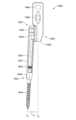
図31に図示されている第2のシム1820の斜視図、正面図、背面図、右側面図、左側面図、上面図、及び底面図が、それぞれ、図32~図38に図示されている。図32~図38に図示されている取り付け構成要素1834は、椎骨係合又は挿入位置(例えば、取り付け構成要素1834の第2の部分1844が椎骨組織と係合したかのような挿入位置)で示されており、取り付け構成要素1834の近位部分は、ガイド1830の近位端の近位に延在している。The perspective, front, rear, right side, left side, top, and bottom views of the
図32に図示されている第2のシム1820の斜視図は、シム本体1832が開創器ブレードと係合するように構成されている取り付け領域1825から前向き及び側方方向にオフセットされるような第2のシム1820のオフセット部分1826を示す。第2のシム1820のオフセット部分1826の前向き及び側方方向のオフセット位置は、第2のシム1820が挿入される開創器ブレード又は開創器アセンブリの他の開創器ブレードとガイド1830が干渉することなく、開創器ブレード内で第2のシム1820を位置付けることを容易にし得るが、一方で、ガイド1830を、第1のシムが係合し得る椎間板に隣接する椎骨と整列することも容易にし得る(例えば、図30参照。32 shows the offset
シム本体1832は、係合構成要素を含むものとして図32に図示されている。例えば、シム本体1832は、第2のシム1820が開創器ブレードと係合されると、第2のシム1820を除去及び/又は調整することを容易にするために、シム設置ツールと係合するように構成された係合特徴1846(例えば、図32~図38に図示されるような開口、窪み、隆起など)を含み得る。追加的又は代替的に、シム本体1832は、シム設置ツールと係合するように構成されたタブ1848(例えば、可撓性係合タブ及び/又は他の好適なタブ)を含み得る。いくつかの場合、タブ1848は、第2のシム1820が開創器ブレードに対する第2のシム1820の意図しない後退を防止するように挿入される、開創器ブレードと係合するように構成された後縁又は後側を有し得るが、これは必須ではない。第2のシム1820のための他の好適な係合特徴が企図される。The
図33に図示されている第2のシム1820の正面図は、第1の長手方向軸L1(例えば、ガイド1830の中心長手方向軸又は他の好適な軸)を有するシムガイド1830と、第2の長手方向軸L2(例えば、シム本体1832の取り付け領域1825の中心長手方向軸又は他の好適な軸)を有するシム本体1832とを示し、第1の長手方向軸L1は、第2の長手方向軸L2に対して角度Aである。第1の長手方向軸L1と第2の長手方向軸L2との間の角度Aは、開創器ブレード又は外科的部位内への第2のシム1820の挿入を容易にするために、かつ第2のシム1820が開創器ブレード内に位置付けられたときに、ガイド1830及び取り付け構成要素1834を椎骨組織と整列させるために好適な任意の所望の角度に設定され得る。角度Aは、限定されるものではないが、取り付け構成要素1834の長さ、第2のシム1820が椎間組織内にあるときの椎体又は椎骨組織に対するガイド1830の意図された場所などを含む様々な因子のうちのいずれか1つ以上に基づいて設定され得る。角度Aは、例えば、0度~10度、1度~5度の値、又は第1のシム1810、若しくは第2のシム1820が位置付けられる開創器ブレードによって係合された椎間組織に隣接する椎骨組織とガイド1830を整列させるように構成された他の好適な値であり得る。一例では、角度Aは、第1の長手方向軸L1が第2の長手方向軸L2に対して平行であるように、0度であってもよい。別の例では、角度Aは、図33に図示されるように、3度であってもよい。角度Aの他の好適な値も企図される。 33 shows the
図34に図示されている第2のシム1820の背面図は、細長い係合部材1850を有するシム本体1832を示す。細長い係合部材1850は、開創器ブレード内で第2のシム1820を位置付けることを容易にするために、開創器ブレードの内面に沿って延びる細長いスロット部材と摺動可能に係合するように構成され得る。細長い係合部材1850は、開創器ブレードのスロット部材と摺動可能に係合するように構成された、任意の好適な形状又は構成を採用し得る。細長い係合部材1850は、図34に図示されるように、シム本体1832の取り付け領域1825の側面でシム本体1832の長さに沿って延在し得るが、他の構成も企図される。The rear view of the
第2のシム1820の右側面図及び左側面図が図35及び図36に図示される。上述されたように、取り付け構成要素1834は、第2のシム1820のガイド1830内の椎骨係合位置にある。ガイド1830及び取り付け構成要素1834は、取り付け構成要素1834がガイド1830内に完全に挿入されたときに、取り付け構成要素1834の近位ヘッド1840の遠位端がガイド1830の第1の部分1836の近位端から距離Dだけ離隔されるように構成され得る(ガイド1830及び椎骨組織内に完全に挿入された取り付け構成要素1834を示す図41Cを参照されたい)。近位ヘッド1840の遠位端と第1の部分1836の近位端との間の距離Dは、ガイド1830、シム本体1832、したがって、椎骨組織と係合する取り付け構成要素1834に対する(例えば、取り付け構成要素1834の軸に対する、又はそれに沿った)開創器アセンブリのある程度の移動を可能にすることに起因して、椎骨組織からの取り付け構成要素1834の引き出しを軽減することを容易にし得る。Right and left side views of the
近位ヘッド1840の遠位端とガイド1830の第1の部分1836の近位端との間の距離Dは、十分な開創器アセンブリの安定化を依然として提供しつつ、重力、脊椎移動、手術中のツール嵌入などに起因する、係合構成要素に対する開創器アセンブリのある程度の移動を可能にする任意の好適な値であり得る。例えば、距離Dの値は、1ミリメートル(millimeter、mm)~5mm又は他の好適な距離であり得る。一例では、距離Dは3mmであってもよいが、距離Dの他の好適な値も企図される。The distance D between the distal end of the
ガイド1830は、所望に応じて、シム本体1832と一列であるか、シム本体1832に対して前方方向にオフセットされるか、又はシム本体1832に対して後方方向にオフセットされ得る。追加的又は代替的に、ガイド1830の長手方向軸(例えば、長手方向軸L1又は他の好適な長手方向軸)は、シム本体1832の長手方向軸(例えば、長手方向軸L2又は他の好適な長手方向軸)における軸又はそれに平行な軸に対して、限定されるものではないが、シム本体1832の長手方向軸における軸又はそれに平行な軸に対して前方又は後方方向に0~10度の角度を含む、任意の好適な角度で後方若しくは前方にオフセットされ得る。図35及び図36に図示されるように、ガイド1830は、シム本体1832に平行であり(例えば、シム本体1832の長手方向軸における軸又はそれに平行な軸に対して0度でオフセットしている)、シム本体1832に対して前方方向にオフセットしているが、これは必須ではない。シム本体1832に対するガイド1830の後方又は前方オフセットは、限定されるものではないが、取り付け構成要素1834の長さ、第2のシム1820が椎体内にあるときの椎体に対するガイド1830の意図された場所などを含む、様々な因子のうちのいずれか1つ以上に基づいて設定され得る。 The
第2のシム1820の上面図及び底面図が図37及び図38に図示されている。オフセット部分1826のガイド1830は、図37及び図38に図示されるように、シム本体1832の前方かつ側面に位置付けられる。Top and bottom views of the
取り付け構成要素1834の近位ヘッド1840は、図37に図示されるように、ガイド1830を通って取り付け構成要素1834を椎骨組織内に挿入するための、又は取り付け構成要素1834を椎骨組織及びガイド1830から除去するためのツールを受容するように構成されたソケット1852を含み得る。限定されるものではないが、六角形を有するヘッド、星形を有するヘッド、プラスドライバーを受容するように構成されたヘッド、マイナスドライバーを受容するように構成されたヘッド、又は他の好適なヘッド構成を含む、他の好適なヘッド構成が企図される。The
いくつかの場合、近位ヘッド1840内のソケット1852を利用することは、取り付け構成要素1834の挿入又は除去を容易にし得る。一例では、ソケット1852は、ツールが中に挿入されたときに近位ヘッド1840に半径方向外向きの圧力を加えることによって近位ヘッドを把持し得るツールの使用を可能にすることによって、取り付け構成要素1834の挿入又は除去を容易にし得、半径方向外向きの圧力は、近位ヘッド1840の内面を把持し、ツールが回転されたときに取り付け構成要素1834が押されるか、又は引っ張られることを可能にする。追加的又は代替的に、取り付け構成要素1832の近位ヘッド1840に挿入されたツールのリップは、ツールが除去方向(例えば、反時計回り方向)に回転されたときに近位ヘッド1840とツールとの間に機械的干渉が生じて、ツールが回転された際にユーザが取り付け構成要素1834に引張力を加えることを可能にするように、近位ヘッド1840のオーバーハングと係合し得る。In some cases, utilizing a
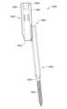
取り付け構成要素1834の遠位端は、図38の底面図に図示されるように、遠位先端1853を含み得、そこに向かって、取り付け構成要素1834の第2の部分1844のねじ山がテーパ状になり得る。いくつかの場合、遠位先端1853及びねじ山は、取り付け構成要素1834の回転移動、取り付け構成要素1834への軸方向圧力、又はその両方の際に、椎骨組織と係合し、その中に穿孔するように構成され得る。The distal end of the mounting
第2のシム1820のガイド1830は、図32~図38に図示されるように、シム本体1832、ガイドが位置付けられ得る開創器ブレード、又は両方に対して固定され得るが、これは必須ではない。いくつかの場合、第2のシム1820のガイド1830は、例えば、図39及び図40に図示されるように、シム本体1832、又はシム本体1832が位置付けられるように構成されている開創器ブレードに対して、調整又は移動する(例えば、並進、回転、枢動など、又は移動の任意の組み合わせ)ように構成され得る。いくつかの場合、第2のシム1820に対するガイド1830の移動は、ユーザ(例えば、外科医又は他の好適なユーザ)が、対象の椎骨内の椎骨の所望の場所に取り付け構成要素1834を設置することを可能にすることを容易にし得る。The
図39に図示される第2のシム1820のガイド1830は、シム本体1832の少なくとも一部分に対して側方内向き又は外向きに並進又は回転するように構成され得る(例えば、ガイド1830の並進又は回転は、図39の破線及び矢印R1によって表される)。他の構成が企図されるが、ガイド1830は、ガイド1830の第1の長手方向軸L1及びシム本体1832の第2の長手方向軸L2の一方又は両方に平行であり得る第3の長手方向軸L3を中心として並進又は回転するように構成され得る。 The
シム本体1832に対するガイド1830の側方内向き又は外向きの並進又は回転移動を容易にするために、ガイド1830は、移動を容易にする任意の好適な構成でシム本体1832に結合され得る。例えば、ガイド1830は、ヒンジ、可撓性部材、自由度に対する制限の有無にかかわらず玉継手、又は他の好適な調整可能な接続を介して、シム本体1832に結合され得る。一例では、ガイド1830は、2つ以上のプリセット位置を有するヒンジ部材を用いてシム本体1832に結合され得るが、他の調整可能な結合技術が企図される。To facilitate lateral inward or outward translational or rotational movement of the
いくつかの場合、第2のシム1820のガイド1830は、図40に図示されるように、シム本体1832に対して枢動又は回転するように構成され得る(例えば、ガイド1830の枢動は、図40の破線及び矢印R2によって表される)。他の構成も企図されるが、ガイド1830は、1つ以上の軸を中心として枢動するように構成され得る。一例では、ガイド1830は、シム本体1832の長手方向軸L2に垂直である1つ以上の軸を中心として枢動するように構成され得るが、これは必須ではない。 In some cases, the
シム本体1832に対するガイド1830の枢動を容易にするために、ガイド1830は、シム本体1832又は第2のシム1820の他の部分に、移動を容易にする任意の好適な構成で結合され得る。例えば、ガイド1830は、ピン、自由度に対する制限の有無にかかわらず玉継手、又は他の好適な調整可能な接続を介して、シム本体1832又は第2のシムの他の部分に結合され得る。一例では、ガイド1830は、枢動ピン1854を用いてシム本体1832又は第2のシム1820の他の部分に結合され得るが(枢動ピン1854は、図40に図示されているが、枢動ピン1854は、取り付け構成要素1834の背後にある)、他の調整可能な結合技術も企図される。To facilitate pivoting of the
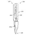
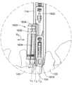
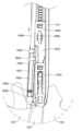
図41A~図41Cは、第2のシム1820(例えば、開創器アセンブリのための第2の安定器)を後方開創器ブレード114に沿って外科的部位に挿入するための技術を図示する。第2のシム1820は、例えば、図41Aに図示されるように、ガイド1830と、シム本体1832と、取り付け構成要素1834の遠位端がガイド1830の第2の部分1838によって覆われる挿入/引き抜き位置(例えば、装填/装填解除位置)までガイド1830内に挿入される取り付け構成要素1834と、を含み得る。上述されたように、挿入/引き抜き位置では、取り付け構成要素1834の第1の部分1842(図41Aには図示せず)のねじ山は、取り付け構成要素1834の椎骨結合部分1844のねじ山の遠位端がガイド1830(例えば、ガイド1830の第2の部分1838)によって覆われるように、ガイド1830の第1の部分1836と係合し得る。第2のシム1820は、後方開創器ブレード114内に挿入されるものとして図示されているが、第2のシム1820は、手術用通路を作成するために使用される開創器アセンブリの1つ以上の他の開創器ブレード内に挿入され得る。41A-41C illustrate a technique for inserting a second shim 1820 (e.g., a second stabilizer for a retractor assembly) into a surgical site along the
最初に、第1のシム1810(例えば、開創器アセンブリのための第1の安定器)は、対象の椎間板組織124と係合され得(例えば、対象が腹臥位であり得る場合)、第1のシム1810は、開創器アセンブリの後方開創器ブレード114と結合され得る。第1のシム1810が椎間板組織124内に位置付けられると、対象内の外科用通路(例えば、側方外科用通路又は他の好適な外科用通路)が、開創器アセンブリを使用して形成され得る。取り付け構成要素1834が挿入/引き抜き位置にあり、後方開創器ブレード114及び第1のシム1810が椎間組織124に又はその中に位置付けられ、対象内に外科用通路を形成している状態で、シム本体1832は、後方開創器ブレード114の溝と係合し得、シム本体1832の遠位端が第1のシム1810の近位端に近接又は接触するまで、後方開創器ブレード144に沿って遠位に前進し得る(例えば、1つ以上の他の好適な様式で摺動又は前進し得る)。いくつかの場合、シム設置ツールは、第2のシム1820の係合特徴1846又はタブ1848と係合し得、後方開創器ブレード114に沿って第2のシム1820を向けるように前進し得る。後方開創器ブレード114内に第2のシム1820を位置付けるための他の好適な技術が企図される。First, a first shim 1810 (e.g., a first stabilizer for a retractor assembly) may be engaged with the subject's disc tissue 124 (e.g., where the subject may be in a prone position) and the
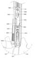
シム本体1832の遠位端が第1のシム1810の近位端に近接した状態で、第2のシム1820が後方開創器ブレード114内に位置付けられると、取り付け構成要素1834は、図41Bに図示されるように、椎骨組織122内に前進して、椎骨組織122と係合し得る。いくつかの場合、取り付け構成要素位置付けツール1858が、取り付け構成要素1834を椎骨組織内に前進させ、対象の脊椎に対して開創器アセンブリを固設するために利用され得る。取り付け構成要素位置付けツール1858が取り付け構成要素1834の近位ヘッド1840と係合した状態で、軸方向力(例えば、ガイド1830に沿った軸方向力)及び回転力が、取り付け構成要素1834に加えられて、取り付け構成要素をガイド1830のねじ山を通してねじ込み、取り付け構成要素1834を椎骨組織122内に前進させ得る。With the distal end of the
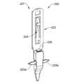
取り付け構成要素1834が椎骨組織122内に完全に挿入されると(例えば、挿入位置になると)、例えば、図41Cに図示されるように、距離Dを有する間隔が、ガイド1830の第1の部分1836の近位端と取り付け構成要素1834の近位ヘッド1840の遠位端との間(例えば、近位ヘッド1840の遠位ショルダ、又は取り付け構成要素1834の第1の直径から第2の直径への移行部)に残って、外科処置中のツール嵌入又は他の力に起因する開創器アセンブリの遊び又は僅かな移動を容易にし得る。いくつかの場合、距離Dの値は、3mmであり得るが、他の好適な値も企図される。取り付け構成要素1834が椎骨組織122内に完全に挿入された状態で、開創器アセンブリの開創器ブレードは、半径方向外向きに拡張され、所望のサイズの外科用又は手術用通路を作成し得る。When the
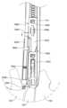
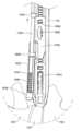
所望の外科用又は手術用通路を利用する外科処置が完了した後、又は1つ以上の他の好適な時点で、第2のシム1820は、椎骨組織又は開創器アセンブリから除去され得る。図42A~図42Cは、第2のシム1820(例えば、第2の安定器)を後方開創器ブレード114に沿って外科的部位から除去するための技術を図示する。取り付け構成要素1834が挿入位置において対象の椎骨組織と係合した状態で、取り付け構成要素位置付けツール1858は、取り付け構成要素1834の近位ヘッド1840と係合し得、取り付け構成要素1834の第2の部分1844のねじ山を椎骨組織122から後退又は係合解除させるように、回転され得る(例えば、取り付け構成要素位置付けツール1858が取り付け構成要素1834の挿入のために回転された方向とは逆である方向に)。いくつかの場合、取り付け構成要素位置付けツール1858は、第1の部分1842のねじ山がガイド1830の第1の部分と係合し、遠位先端(例えば、遠位先端1853、図42A~図42Cには図示せず)がガイド1830の第2の部分1838によって覆われるまで、取り付け構成要素位置付けツール1858を引っ張ること(例えば、軸方向又は他の好適な方向に)が、取り付け構成要素134を椎骨組織122から引き抜くのを補助し得るように、近位ヘッド1840に半径方向外向きの圧力を加え得る(例えば、ソケット182を介して)遠位端を有するように構成され得る。取り付け構成要素1834の遠位先端がガイド1830の第2の部分1838によって覆われるとき、取り付け構成要素1834は、例えば、図42Bに図示されるように、挿入/引き抜き位置にあり得る。After the surgical procedure utilizing the desired surgical or surgical passageway is completed, or at one or more other suitable times, the
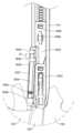
任意選択的に、取り付け構成要素が椎骨組織122から引き抜かれた後、開創器アセンブリは、開創器アセンブリの開創器ブレードによって画定される手術用通路のサイズを低減するように調整され得る。取り付け構成要素1834が挿入/引き抜き位置にあり、任意選択的に、手術用通路が低減されたサイズにある状態で、第2のシム1820は、後方開創器ブレード114又は外科用通路(例えば、側方外科用通路)から引き抜かれるか、又は除去され得る。いくつかの場合、シム設置ツールは、手術用通路内に位置付けられ、係合特徴1846、タブ1848、又は両方と係合され得る。第2のシム1820と係合されると、シム設置ツールは、手術用通路から引き抜かれ得、第2のシム1820は、開創器ブレードに沿って近位に摺動し、手術用通路から出て、開創器アセンブリとの係合から外れ得る。Optionally, after the attachment component is withdrawn from the
他の構成が企図されるが、本明細書で論じられるシムに関するシム本体の例示的な構成、及びシムと開創器アセンブリの開創器ブレードとの間の例示的な結合は、2005年5月25日出願のSURGICAL ACCESS SYSTEM AND RELATED METHODSと題された米国特許出願第11/137,169号に開示されており、この出願は、あらゆる目的のためにその全体が参照により本明細書に組み込まれる。Although other configurations are contemplated, exemplary configurations of the shim body for the shims discussed herein and exemplary connections between the shims and the retractor blades of the retractor assembly are disclosed in U.S. patent application Ser. No. 11/137,169, filed May 25, 2005, entitled SURGICAL ACCESS SYSTEM AND RELATED METHODS, which is hereby incorporated by reference in its entirety for all purposes.
他の構成が企図されるが、本明細書で論じられるシムに関するシム本体の例示的な構成、シムと開創器アセンブリの開創器ブレードとの間の例示的な結合、並びに開創器ブレードに対してシムを調整及び/又は除去するためのツールは、2014年1月27日出願のSURGICAL ACCESS SYSTEM AND RELATED METHODSと題された米国特許出願第13/821,224号に開示されており、この出願は、あらゆる目的のためにその全体が参照により本明細書に組み込まれる。Although other configurations are contemplated, exemplary configurations of the shim body for the shims discussed herein, exemplary couplings between the shims and the retractor blades of the retractor assembly, and tools for adjusting and/or removing the shims relative to the retractor blades are disclosed in U.S. patent application Ser. No. 13/821,224, filed Jan. 27, 2014, entitled SURGICAL ACCESS SYSTEM AND RELATED METHODS, which is hereby incorporated by reference in its entirety for all purposes.
他の構成が企図されるが、開創器ブレードに対してシムを調整及び/又は除去するためのツールの例示的な構成は、2014年11月11日出願のCOMBINED INTRADISCAL INSERTION TOOL AND INTRADISCAL SHIMと題された米国特許出願第29/508,821号に開示されており、この出願は、あらゆる目的のためにその全体が参照により本明細書に組み込まれる。Although other configurations are contemplated, an exemplary configuration of a tool for adjusting and/or removing a shim from a retractor blade is disclosed in U.S. Patent Application No. 29/508,821, filed Nov. 11, 2014, entitled COMBINED INTRADISCAL INSERTION TOOL AND INTRADISCAL SHIM, which is hereby incorporated by reference in its entirety for all purposes.
以下に定義される用語については、特許請求の範囲又は本明細書の他の箇所において異なる定義が与えられない限り、これらの定義が適用されるものとする。For the terms defined below, these definitions shall apply, unless a different definition is given in the claims or elsewhere in this specification.
全ての数値は、本明細書において、明示的に示されているか否かにかかわらず、「約」という用語によって修飾されると想定される。「約」という用語は、概して、当業者が列挙された値と等しい(例えば、同じ機能又は結果を有する)と考えるであろう数の範囲を指す。多くの場合、「約」という用語は、最も近い有効数字に丸められる数を含み得る。All numerical values are assumed to be modified herein by the term "about," whether or not expressly indicated. The term "about" generally refers to a range of numbers that one of ordinary skill in the art would consider equivalent to the recited value (e.g., having the same function or result). In many instances, the term "about" may include numbers that are rounded to the nearest significant figure.
端点による数値範囲の列挙は、その範囲内の全ての数を含む(例えば、1~5は、1、1.5、2、2.75、3、3.80、4、及び5を含む)。The recitation of numerical ranges by endpoints includes all numbers within that range (e.g., 1 to 5 includes 1, 1.5, 2, 2.75, 3, 3.80, 4, and 5).
本明細書及び添付の特許請求の範囲において使用される場合、単数形「a」、「an」、及び「the」は、内容が明らかに他のことを示さない限り、複数の指示対象を含む。本明細書及び添付の特許請求の範囲において使用される場合、「又は」という用語は、概して、内容が明らかに別のことを指示しない限り、「及び/又は」を含む意味で使用される。As used in this specification and the appended claims, the singular forms "a," "an," and "the" include plural referents unless the content clearly dictates otherwise. As used in this specification and the appended claims, the term "or" is generally used in its sense to include "and/or" unless the content clearly dictates otherwise.
本明細書における「実施形態」、「いくつかの実施形態」、「他の実施形態」などへの言及は、説明される実施形態が1つ以上の特定の特徴、構造、及び/又は特性を含み得ることを示すことに留意されたい。しかしながら、そのような列挙は、全ての実施形態が特定の特徴、構造、及び/又は特性を含むことを必ずしも意味しない。加えて、特定の特徴、構造、及び/又は特性が一実施形態と関連して説明されるとき、そのような特徴、構造、及び/又は特性はまた、明確に反対に述べられない限り、明示的に説明されるか否かにかかわらず、他の実施形態と関連しても使用され得ることを理解されたい。It should be noted that references herein to "an embodiment," "some embodiments," "other embodiments," and the like indicate that the described embodiment may include one or more particular features, structures, and/or characteristics. However, such listing does not necessarily mean that all embodiments include the particular feature, structure, and/or characteristic. In addition, when a particular feature, structure, and/or characteristic is described in connection with one embodiment, it should be understood that such feature, structure, and/or characteristic may also be used in connection with other embodiments, whether or not explicitly described, unless expressly stated to the contrary.
詳細な説明は、図面を参照して読まれるべきであり、異なる図面の同様の要素は、同様の番号を有する。図面は、必ずしも縮尺どおりではなく、例示的な実施形態を図示し、開示の範囲を限定することを意図するものではない。The detailed description should be read with reference to the drawings, in which like elements in different drawings have like numbers. The drawings, which are not necessarily to scale, illustrate illustrative embodiments and are not intended to limit the scope of the disclosure.
本開示は、多くの点で例示的なものにすぎないことを理解されたい。本開示の範囲を超えることなく、詳細に、特に形状、サイズ、及びステップの配置に関して変更が行われ得る。これは、適切な範囲で、他の実施形態で使用される1つの例示的な実施形態の特徴のいずれかの使用を含み得る。本開示の範囲は、当然ながら、添付の特許請求の範囲が表現される文面で定義される。It will be understood that the present disclosure is in many respects merely illustrative. Changes may be made in details, particularly in matters of shape, size, and arrangement of steps, without exceeding the scope of the present disclosure. This may include, to the extent appropriate, the use of any of the features of one illustrative embodiment used in another embodiment. The scope of the present disclosure is, of course, defined in the language in which the appended claims are expressed.
Claims (39)
Translated fromJapaneseシム本体と、
前記シム本体に結合されたガイドと、を備え、
前記シム本体は、開創器アセンブリの開創器ブレードに解放可能に結合するように構成された外科用シム本体であり、
前記ガイドは、取り付け構成要素を受容し、かつ前記シム本体が前記開創器ブレードに結合され、前記開創器ブレードが対象内に外科用通路を形成しているときに、前記取り付け構成要素の遠位端を前記対象の椎骨組織に向けるように構成されている、
アセンブリ。 An assembly comprising: a shim body;
a guide coupled to the shim body;
the shim body being a surgical shim body configured to releasably couple to a retractor blade of a retractor assembly;
the guide is configured to receive an attachment component and direct a distal end of the attachment component toward vertebral tissue of the subject when the shim body is coupled to the retractor blade and the retractor blade forms a surgical channel in the subject.
assembly.
前記ガイドの前記近位端は、前記シム本体の遠位端の近位にあり、前記ガイドの前記遠位端は、前記シム本体の前記遠位端の遠位にある、
請求項1に記載のアセンブリ。 The guide has a proximal end and a distal end;
the proximal end of the guide is proximal to the distal end of the shim body and the distal end of the guide is distal to the distal end of the shim body;
The assembly of claim 1 .
前記取り付け構成要素は、前記ガイドに解放可能に結合するように構成されている、
請求項1に記載のアセンブリ。 the mounting component further comprising:
the mounting component is configured to releasably couple to the guide;
The assembly of claim 1 .
前記第1のねじ山セットが前記ガイドの前記ねじ山と解放可能に係合されたとき、前記第2のねじ山セットの遠位端は前記ガイドによって覆われる、請求項15に記載のアセンブリ。 the first set of threads configured to releasably engage threads of the guide;
The assembly of claim 15 , wherein a distal end of the second set of threads is covered by the guide when the first set of threads is releasably engaged with the threads of the guide.
前記取り付け構成要素の近位端が、前記ガイドチューブの前記内径よりも大きい第1の外径を画定している、
請求項10に記載のアセンブリ。 the guide includes a proximal end defining an inner diameter of a guide tube of the guide;
a proximal end of the mounting component defining a first outer diameter greater than the inner diameter of the guide tube;
11. The assembly of claim 10.
対象の脊椎への手術用通路を確立するように構成された開創器アセンブリと、
前記開創器アセンブリに解放可能に結合され、前記開創器アセンブリが前記手術用通路を確立している間に前記対象の椎間板組織と係合するように構成されている、第1の安定器と、
前記開創器アセンブリに解放可能に結合され、前記開創器アセンブリが前記手術用通路を確立している間に前記対象の椎骨組織と係合するように構成されている、第2の安定器と、を備える、
システム。 1. A system comprising:
a retractor assembly configured to establish a surgical passageway to a subject's spine;
a first stabilizer releasably coupled to the retractor assembly and configured to engage the subject's disc tissue while the retractor assembly is establishing the surgical channel; and
a second stabilizer releasably coupled to the retractor assembly and configured to engage vertebral tissue of the subject while the retractor assembly is establishing the surgical corridor.
system.
前記シム本体は、前記開創器ブレードと係合するように構成されている、請求項22に記載のシステム。 the retractor assembly includes a retractor blade;
The system of claim 22 , wherein the shim body is configured to engage the retractor blade.
前記取り付け構成要素は、前記ガイドに解放可能に結合するように構成されている、
請求項22に記載のシステム。 the second ballast includes a mounting component;
the mounting component is configured to releasably couple to the guide;
23. The system of claim 22.
第1の安定器を対象の椎間板組織と係合させることであって、前記第1の安定器が、開創器アセンブリと結合される、係合させることと、
前記開創器アセンブリを使用して、前記対象内に側方外科用通路を形成することと、
第2の安定器を前記対象の椎骨組織と係合させることであって、前記第2の安定器が、前記開創器アセンブリと結合される、係合させることと、を含む、
方法。 1. A method comprising:
engaging a first stabilizer with a subject disc tissue, the first stabilizer being coupled with a retractor assembly;
creating a lateral surgical channel in the subject using the retractor assembly;
and engaging a second stabilizer with the target vertebral tissue, the second stabilizer being coupled with the retractor assembly.
Method.
前記取り付け構成要素の第2のねじ山セットの遠位端は、前記取り付け構成要素の前記第1のねじ山セットが前記ガイドの前記ねじ山と係合されるときに、前記ガイドによって覆われる、請求項31に記載の方法。 further comprising engaging a first set of threads of the mounting component with threads of the guide;
32. The method of claim 31, wherein a distal end of a second set of threads of the mounting component is covered by the guide when the first set of threads of the mounting component is engaged with the threads of the guide.
39. The method of claim 38, wherein the withdrawing the second stabilizer from the lateral surgical channel comprises disengaging the shim body from the blades of the retractor assembly.
Applications Claiming Priority (6)
| Application Number | Priority Date | Filing Date | Title |
|---|---|---|---|
| US202263428861P | 2022-11-30 | 2022-11-30 | |
| US63/428861 | 2022-11-30 | ||
| US202363486847P | 2023-02-24 | 2023-02-24 | |
| US63/486847 | 2023-02-24 | ||
| US202318523337A | 2023-11-29 | 2023-11-29 | |
| US18/523337 | 2023-11-29 |
Publications (1)
| Publication Number | Publication Date |
|---|---|
| JP2024079660Atrue JP2024079660A (en) | 2024-06-11 |
Family
ID=89029637
Family Applications (1)
| Application Number | Title | Priority Date | Filing Date |
|---|---|---|---|
| JP2023202974APendingJP2024079660A (en) | 2022-11-30 | 2023-11-30 | Surgical retractor systems and components |
Country Status (2)
| Country | Link |
|---|---|
| EP (1) | EP4378399A1 (en) |
| JP (1) | JP2024079660A (en) |
Citations (4)
| Publication number | Priority date | Publication date | Assignee | Title |
|---|---|---|---|---|
| JP2013509982A (en)* | 2009-11-10 | 2013-03-21 | ニューベイシブ・インコーポレイテッド | Method and apparatus for performing spinal surgery |
| US20130190575A1 (en)* | 2011-08-31 | 2013-07-25 | Lanx, Inc. | Lateral Retractor System and Methods of Use |
| US9044280B1 (en)* | 2008-10-13 | 2015-06-02 | Nuvasive, Inc. | Surgical access system and related methods |
| JP2017535324A (en)* | 2014-10-21 | 2017-11-30 | グローバス メディカル インコーポレイティッド | Implantable orthopedic tools |
Family Cites Families (4)
| Publication number | Priority date | Publication date | Assignee | Title |
|---|---|---|---|---|
| CN102497828B (en)* | 2009-05-20 | 2015-09-09 | 斯恩蒂斯有限公司 | What patient installed retracts part |
| US9307972B2 (en)* | 2011-05-10 | 2016-04-12 | Nuvasive, Inc. | Method and apparatus for performing spinal fusion surgery |
| US9113853B1 (en)* | 2011-08-31 | 2015-08-25 | Nuvasive, Inc. | Systems and methods for performing spine surgery |
| US10987129B2 (en)* | 2015-09-04 | 2021-04-27 | Medos International Sarl | Multi-shield spinal access system |
- 2023
- 2023-11-30JPJP2023202974Apatent/JP2024079660A/enactivePending
- 2023-11-30EPEP23213509.5Apatent/EP4378399A1/ennot_activeWithdrawn
Patent Citations (4)
| Publication number | Priority date | Publication date | Assignee | Title |
|---|---|---|---|---|
| US9044280B1 (en)* | 2008-10-13 | 2015-06-02 | Nuvasive, Inc. | Surgical access system and related methods |
| JP2013509982A (en)* | 2009-11-10 | 2013-03-21 | ニューベイシブ・インコーポレイテッド | Method and apparatus for performing spinal surgery |
| US20130190575A1 (en)* | 2011-08-31 | 2013-07-25 | Lanx, Inc. | Lateral Retractor System and Methods of Use |
| JP2017535324A (en)* | 2014-10-21 | 2017-11-30 | グローバス メディカル インコーポレイティッド | Implantable orthopedic tools |
Also Published As
| Publication number | Publication date |
|---|---|
| EP4378399A1 (en) | 2024-06-05 |
Similar Documents
| Publication | Publication Date | Title |
|---|---|---|
| US12167970B2 (en) | Expandable inter vertebral implant | |
| US12268612B2 (en) | Expandable intervertebral implant | |
| EP1626662B1 (en) | Tissue retractor for minimally invasive surgery | |
| US9119725B2 (en) | Expandable vertebral body replacement system and method | |
| US9492289B2 (en) | Expandable intervertebral implant | |
| US8114131B2 (en) | Extension limiting devices and methods of use for the spine | |
| US9486330B2 (en) | Minimally invasive method and surgical tools for trans-PSOAS approach | |
| US9055981B2 (en) | Spinal implants and methods | |
| US9370384B2 (en) | Bone fixation rod and implantation device for insertion thereof | |
| US20050251192A1 (en) | Access device having discrete visualization locations | |
| US20050075644A1 (en) | Methods and apparatuses for minimally invasive replacement of intervertebral discs | |
| US20100168858A1 (en) | Expandable interbody implant and method | |
| CN104220017A (en) | Telescoping interspinous fixation device and methods of use | |
| WO2007038429A1 (en) | Methods and apparatuses for stabilizing the spine through an access device | |
| JP2009533187A (en) | Posterior spine apparatus and method | |
| JP2007515988A (en) | Device and method for delivering an implant from an annular defect of an intervertebral disc | |
| JP2024079660A (en) | Surgical retractor systems and components | |
| TW202112320A (en) | Expandable and adjustable lordosis interbody fusion system |
Legal Events
| Date | Code | Title | Description |
|---|---|---|---|
| A521 | Request for written amendment filed | Free format text:JAPANESE INTERMEDIATE CODE: A523 Effective date:20231201 | |
| A521 | Request for written amendment filed | Free format text:JAPANESE INTERMEDIATE CODE: A523 Effective date:20240130 | |
| A621 | Written request for application examination | Free format text:JAPANESE INTERMEDIATE CODE: A621 Effective date:20240130 | |
| AA79 | Non-delivery of priority document | Free format text:JAPANESE INTERMEDIATE CODE: A24379 Effective date:20240409 | |
| A977 | Report on retrieval | Free format text:JAPANESE INTERMEDIATE CODE: A971007 Effective date:20241009 | |
| A131 | Notification of reasons for refusal | Free format text:JAPANESE INTERMEDIATE CODE: A131 Effective date:20241022 | |
| A601 | Written request for extension of time | Free format text:JAPANESE INTERMEDIATE CODE: A601 Effective date:20250122 | |
| A521 | Request for written amendment filed | Free format text:JAPANESE INTERMEDIATE CODE: A523 Effective date:20250319 | |
| A02 | Decision of refusal | Free format text:JAPANESE INTERMEDIATE CODE: A02 Effective date:20250603 |