JP2024079086A - Knob retention structure and smart lock - Google Patents
Knob retention structure and smart lockDownload PDFInfo
- Publication number
- JP2024079086A JP2024079086AJP2022191806AJP2022191806AJP2024079086AJP 2024079086 AJP2024079086 AJP 2024079086AJP 2022191806 AJP2022191806 AJP 2022191806AJP 2022191806 AJP2022191806 AJP 2022191806AJP 2024079086 AJP2024079086 AJP 2024079086A
- Authority
- JP
- Japan
- Prior art keywords
- knob
- holder
- smart lock
- pair
- holding structure
- Prior art date
- Legal status (The legal status is an assumption and is not a legal conclusion. Google has not performed a legal analysis and makes no representation as to the accuracy of the status listed.)
- Pending
Links
Images


Classifications
- E—FIXED CONSTRUCTIONS
- E05—LOCKS; KEYS; WINDOW OR DOOR FITTINGS; SAFES
- E05B—LOCKS; ACCESSORIES THEREFOR; HANDCUFFS
- E05B47/00—Operating or controlling locks or other fastening devices by electric or magnetic means
- E05B47/02—Movement of the bolt by electromagnetic means; Adaptation of locks, latches, or parts thereof, for movement of the bolt by electromagnetic means
- G—PHYSICS
- G07—CHECKING-DEVICES
- G07C—TIME OR ATTENDANCE REGISTERS; REGISTERING OR INDICATING THE WORKING OF MACHINES; GENERATING RANDOM NUMBERS; VOTING OR LOTTERY APPARATUS; ARRANGEMENTS, SYSTEMS OR APPARATUS FOR CHECKING NOT PROVIDED FOR ELSEWHERE
- G07C9/00—Individual registration on entry or exit
- G07C9/00174—Electronically operated locks; Circuits therefor; Nonmechanical keys therefor, e.g. passive or active electrical keys or other data carriers without mechanical keys
- G07C9/00944—Details of construction or manufacture
- E—FIXED CONSTRUCTIONS
- E05—LOCKS; KEYS; WINDOW OR DOOR FITTINGS; SAFES
- E05B—LOCKS; ACCESSORIES THEREFOR; HANDCUFFS
- E05B17/00—Accessories in connection with locks
- E05B17/22—Means for operating or controlling lock or fastening device accessories, i.e. other than the fastening members, e.g. switches, indicators
- E—FIXED CONSTRUCTIONS
- E05—LOCKS; KEYS; WINDOW OR DOOR FITTINGS; SAFES
- E05B—LOCKS; ACCESSORIES THEREFOR; HANDCUFFS
- E05B49/00—Electric permutation locks; Circuits therefor ; Mechanical aspects of electronic locks; Mechanical keys therefor
- G—PHYSICS
- G07—CHECKING-DEVICES
- G07C—TIME OR ATTENDANCE REGISTERS; REGISTERING OR INDICATING THE WORKING OF MACHINES; GENERATING RANDOM NUMBERS; VOTING OR LOTTERY APPARATUS; ARRANGEMENTS, SYSTEMS OR APPARATUS FOR CHECKING NOT PROVIDED FOR ELSEWHERE
- G07C9/00—Individual registration on entry or exit
- G07C9/00174—Electronically operated locks; Circuits therefor; Nonmechanical keys therefor, e.g. passive or active electrical keys or other data carriers without mechanical keys
- G07C9/00563—Electronically operated locks; Circuits therefor; Nonmechanical keys therefor, e.g. passive or active electrical keys or other data carriers without mechanical keys using personal physical data of the operator, e.g. finger prints, retinal images, voicepatterns
- E—FIXED CONSTRUCTIONS
- E05—LOCKS; KEYS; WINDOW OR DOOR FITTINGS; SAFES
- E05B—LOCKS; ACCESSORIES THEREFOR; HANDCUFFS
- E05B47/00—Operating or controlling locks or other fastening devices by electric or magnetic means
- E05B2047/0083—Devices of electrically driving keys, e.g. to facilitate opening
- E—FIXED CONSTRUCTIONS
- E05—LOCKS; KEYS; WINDOW OR DOOR FITTINGS; SAFES
- E05B—LOCKS; ACCESSORIES THEREFOR; HANDCUFFS
- E05B47/00—Operating or controlling locks or other fastening devices by electric or magnetic means
- E05B2047/0091—Retrofittable electric locks, e.g. an electric module can be attached to an existing manual lock
- E—FIXED CONSTRUCTIONS
- E05—LOCKS; KEYS; WINDOW OR DOOR FITTINGS; SAFES
- E05B—LOCKS; ACCESSORIES THEREFOR; HANDCUFFS
- E05B47/00—Operating or controlling locks or other fastening devices by electric or magnetic means
- E05B47/0001—Operating or controlling locks or other fastening devices by electric or magnetic means with electric actuators; Constructional features thereof
- E05B47/0012—Operating or controlling locks or other fastening devices by electric or magnetic means with electric actuators; Constructional features thereof with rotary electromotors
Landscapes
- Physics & Mathematics (AREA)
- General Physics & Mathematics (AREA)
- Engineering & Computer Science (AREA)
- Manufacturing & Machinery (AREA)
- Electromagnetism (AREA)
- Casings For Electric Apparatus (AREA)
- Lock And Its Accessories (AREA)
Abstract
Description
Translated fromJapanese本発明は、ノブ保持構造及びスマートロックに関する。The present invention relates to a knob holding structure and a smart lock.
スマートロックは、パスワード入力、指紋認証、又はスマートホン等の電子機器からの遠隔操作等によってドアの開錠・施錠を行う装置であり、サムターン等のドアノブを保持する保持手段と、該保持手段を回転駆動する駆動手段とを備えるものが知られている。A smart lock is a device that unlocks and locks doors by password entry, fingerprint authentication, or remote operation from an electronic device such as a smartphone. It is known that the smart lock is equipped with a holding means for holding a doorknob such as a thumb turn, and a driving means for rotating the holding means.
ドアに対するスマートロックの取付け位置に誤差がある場合に、その誤差を吸収できる機構が提唱されている。例えば、サムターンを固定するカバーの内側にソフトラバースリーブを挿入した構成を有するスマートロック装置が知られている。Mechanisms have been proposed that can absorb errors when there is an error in the installation position of a smart lock relative to a door. For example, a smart lock device is known that has a soft rubber sleeve inserted inside the cover that secures the thumb turn.
またサムターンを回転させるカップリングとしてゴム、スポンジ、ロボットフィンガー等を用いて、ドアロックとドア設置機構との間のずれや偏心を補正する技術が知られている。There is also known technology that uses rubber, sponge, robotic fingers, etc. as a coupling to rotate the thumb turn to correct misalignment or eccentricity between the door lock and the door installation mechanism.
スマートロックをドア等に取付ける際は、ドアノブの保持手段をドアノブに対して、それらの回転中心が整合した状態で確実に固定するために、両者を位置決めした上でネジ等を用いて固定していた。しかしこのような位置決め及び固定は、作業者にとって煩雑かつ面倒な作業となっていた。When attaching a smart lock to a door, etc., the doorknob holding means and the doorknob are positioned and then fixed with screws or the like to ensure that their centers of rotation are aligned. However, such positioning and fixing is a complicated and tedious task for the worker.
また上述のように位置決め誤差を吸収する技術もいくつか提唱されてはいるが、より簡易な構成で、位置決め及び固定に関する作業を効率化できる構造を備えたノブ保持構造及びスマートロックが望まれる。As mentioned above, several technologies have been proposed to absorb positioning errors, but what is needed is a knob holding structure and smart lock that has a simpler configuration and is structured to streamline positioning and fixing tasks.
本開示の一態様は、ホルダと、前記ホルダ内に互いに対向して配置された一対の挟圧部材と、前記一対の挟圧部材の各々を、前記ホルダの内壁に対して変位可能に支持するとともに、前記一対の挟圧部材を互いに接近する方向に付勢する弾性部材と、を有する、スマートロックのノブ保持構造である。One aspect of the present disclosure is a knob holding structure for a smart lock, comprising a holder, a pair of clamping members arranged opposite each other within the holder, and an elastic member that supports each of the pair of clamping members so that they can be displaced relative to the inner wall of the holder and biases the pair of clamping members in a direction that brings them closer to each other.
本開示の他の態様は、上記ノブ保持構造と、前記ホルダを遠隔操作により回転駆動する駆動機構と、を有するスマートロックである。Another aspect of the present disclosure is a smart lock having the above-mentioned knob holding structure and a drive mechanism that rotates the holder by remote control.
本開示によれば、ドア等にスマートロックを取付ける際に一対の挟圧部材がノブの位置や形状に応じて自動的に弾性変位することができるので、作業者の手間を大幅に削減しつつ、適切にノブを保持することができる。According to the present disclosure, when attaching a smart lock to a door or the like, a pair of clamping members can automatically elastically displace according to the position and shape of the knob, allowing the knob to be held properly while significantly reducing the labor required by the worker.
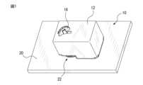
図1は、好適な実施形態に係るスマートロック10の斜視図であり、図2はスマートロック10を図1とは別角度からみた斜視図である。スマートロック10は、筐体12と、筐体12内に配置されるノブ保持構造14と、筐体12内に配置され、ノブ保持構造14を筐体12に対して回転駆動する駆動機構50(図7参照)とを有する。スマートロック10は例えば、図3に部分的に示すようなドア20に設けられたサムターン式のノブ22を遠隔操作により回転させることができるように構成されている。例えば、ノブ保持構造14がノブ22を保持した状態で、駆動機構50がスマートホン等の電子機器(図示せず)からの遠隔操作によってノブ保持構造14を回転駆動することでノブ22を回転させることができる。なおノブ22はサムターンに限らず、レバーやラッチ等、回転又は移動させることでドアを開閉するものが含まれる。1 is a perspective view of a
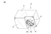
スマートロック10はドア20に対し、種々の手段によって取付け可能である。例えば、図2に示すようなスマートロック10の取付け面18を、図示しない両面粘着テープ又は接着剤等を用いてドア20の適所に貼り付けることができる。また図1に示すように、スマートロック10は、ノブ保持構造14に接続された操作ノブ16を有してもよく、これによりノブ22を手動でも回転させることができる。操作ノブ16は例えば、図6に示す回転軸部44に接続されている。The
図4は、ノブ保持構造14の構成例を、ドア20に取付けられる側(以下、底面側とも称する)から見た図である。ノブ保持構造14は、ホルダ24と、一対の挟圧部材26a及び26bと、挟圧部材26a及び26bをそれぞれ、ホルダ24の内壁に対して弾性変位可能に支持するとともに、挟圧部材26a及び26bを互いに接近する方向に付勢する弾性部材28a及び28bとを有する。図示例では、挟圧部材26a及び26bは板状の部材(以下、挟み板とも称する)であり、弾性体28a及び28bは複数のコイルばねである。なおコイルばねの個数に特段の制約はない。Figure 4 shows an example of the configuration of the
一対の挟み板26a及び26bは、底面側において所定の間隔だけ互いに離隔して配置されている。図示例では、一対の挟み板26a及び26bは、それぞれコイルばね28a及び28bによって互いに接近する方向に付勢されるが、ホルダ24の一部として構成された支持部30によって、一定の距離だけ離隔した状態に維持される。The pair of
より具体的には、支持部30は、ホルダ24の一部に、一対の挟み板26a及び26bが互いに接離する方向に延びるスリット32a及び32bを形成することで略T字形状部分として形成され、一方、挟み板26a及び26bはそれぞれ、スリット32a及び32b内を移動可能な突起34a及び34bを有する。このような構成により、挟み板26a及び26bは、スリット32a及び32bの長さに相当する範囲内で互いに接離する方向に弾性変位することができる。またスリット32a及び32bにより、挟み板26a及び26bの可動方向は実質的に接離方向に限定可能となるため、挟み板26a及び26bの動作が安定し、ノブ22を適切に保持することができる。但しこれは一例であり、例えば支持部30がない構成でも、コイルばね28a及び28bの個数、寸法、ばね定数等を適宜選択することにより、一対の挟み板26a及び26bを適当な間隔で互いに離隔配置することができる。More specifically, the
図1のようにスマートロック10をドア20に取付ける際は、作業者が、一対の挟み板26a及び26bの間の隙間36内にノブ22が挿入されるように筐体12を操作する。取付け前の隙間36はノブ22の厚さよりもいくらか小さい幅を有することが望ましいが、上述のように挟み板26a及び26bはそれぞれコイルばね28a及び28bに支持されているので、ノブ22に押し当てられたときに挟み板26a及び26bの少なくとも一方は互いに接離する方向に弾性変位する。従って、作業者が筐体12をノブ22に対して正確に位置決めしなくても、ノブ22は隙間36内に好適に挿入される。When attaching the
なおノブ22の挿入をより容易にすべく、図4に示すように、挟み板26a及び26bはそれぞれ、底面側に面する部位(端面)においてテーパ面38a及び38bを有することが好ましい。テーパ面38a及び38bの形状によっては、取付け前の一対の挟み板26a及び26bは互いに当接していてもよいが、上述の支持部30によって所定距離だけ離隔された状態の方が、ノブ22の挿入のし易さの観点からは好ましい。なおテーパ面は、一方の挟み板のみに設けてもよい。In order to make it easier to insert the
ノブ22が隙間36内に挿入されると、コイルばね28a及び28bのばね圧に逆らって挟み板26a及び26bの間隔が広がり、ノブ22は挟み板26a及び26bの間に挟圧された状態となる。このとき、ノブ22に対するホルダ24の位置は、コイルばね28a及び28bのばね圧のバランスにより、ノブ22の回転中心とホルダ24の回転中心が一致するように自動的に調整される。よって作業者は、手間のかかる位置決めや調整を要さない簡易な操作によって、スマートロック10を実用に十分な精度でドア20に対して取付けることができる。When the
ノブ22がホルダ24に保持された状態、より具体的には挟み板26a及び26bの間に挟圧された状態では、後述する駆動機構50によってホルダ24ごとノブ22を回転させることができる。またホルダ24の回転角度がノブ22の仕様等に基づく最大回転角度より大きくなった場合、コイルばね28a及び28bの少なくとも一方が弾性変位することでホルダ24の余剰の回転移動が吸収されるので、ノブ22に過度の力が作用することが抑制される。When the
図5は、ノブ保持構造14を、底面側とは反対側の上面側から見た図であり、図6は図5のA-A線に沿う断面図である。ホルダ24は、挟み板26a及び26bの各々を互いに接離する方向に揺動可能に支持するように構成されており、図示例ではホルダ24の上面に穴又は凹部40a及び40bを形成し、穴40a及び40bにはそれぞれ、挟み板26a及び26bの上面側に形成された突起42a及び42bが係合している。このような構成によれば、図6に示すように挟み板26a及び26bはそれぞれ、穴40a及び40bを支点とした揺動動作が可能となるので、取付け時により安定的にノブ22を挟圧して保持できるようになる。Figure 5 is a view of the
ノブ保持構造14を構成する各部材の材料について特段の制約はないが、ホルダ24及び挟み板26a及び26bは、製造のし易さや重量の観点から樹脂製であることが好ましく、コイルばね28a及び28bは金属製であることが好ましい。またコイルばね以外の弾性体も使用可能であり、例えば板ばね、ゴム、スポンジも使用可能である。There are no particular restrictions on the materials of the components that make up the
図7は、ノブ保持構造14を回転駆動するための駆動機構50の一構成例を示す。駆動機構50は、駆動モータ52と、駆動モータ52の回転トルクをホルダ24に伝達するギヤユニット54とを有し、その全体は筐体12内に収容可能である。但し図7では説明のため、筐体12については、取付け面18(図2)を有する底部62のみを図示している。Figure 7 shows an example of the configuration of a
筐体12内には、プロセッサ56等が搭載された制御基板58も収容可能であり、プロセッサ56は、スマートホン等の電子機器からの遠隔操作に基づいて駆動モータ52を制御するように構成されている。The
ギヤユニット54は少なくとも1つのギヤを有し、図示例では直列に係合した3つのギヤ54a、54b及び54cを有する。ギヤ54cがホルダ24の回転軸部44(図5参照)に係合することで、モータ52が回転すると、ホルダ24に保持されたノブ22が回転する。但しこれは一例であり、ギヤユニット54を構成するギヤの個数や歯数は、駆動モータ52の仕様やノブ22の所望の回転速度等に基づいて適宜選択可能である。The
ノブ保持構造14は、手動でも回転させることができることが好ましい。例えば操作ノブ16の回転軸部60をホルダ24の回転軸部44(図5を参照)に接続することで、作業者が操作ノブ16を回転させることにより、ホルダ24に保持されたノブ22を手動で回転させることができる。It is preferable that the
10 スマートロック、12 筐体、14 ノブ保持構造、16 操作ノブ、
18 取付け面、20 ドア、22 ドアノブ、24 ホルダ、
26a,26b 挟圧部材、28a,28b コイルばね、30 支持部、
32a,32b スリット、34a,34b 突起、38a,38b テーパ面、
40a,40b 穴、42a,42b 突起、50 駆動機構、52 モータ、
54 ギヤユニット、56 プロセッサ、58 制御基板 10 Smart lock, 12 Housing, 14 Knob holding structure, 16 Operation knob,
18 Mounting surface, 20 Door, 22 Doorknob, 24 Holder,
26a, 26b: clamping member; 28a, 28b: coil spring; 30: support portion;
32a, 32b: slits; 34a, 34b: protrusions; 38a, 38b: tapered surfaces;
40a, 40b holes, 42a, 42b protrusions, 50 drive mechanism, 52 motor,
54 Gear unit, 56 Processor, 58 Control board
Claims (5)
Translated fromJapanese前記ホルダ内に互いに対向して配置された一対の挟圧部材と、
前記一対の挟圧部材の各々を、前記ホルダの内壁に対して変位可能に支持するとともに、前記一対の挟圧部材を互いに接近する方向に付勢する弾性部材と、
を有する、スマートロックのノブ保持構造。 A holder and
A pair of pressing members disposed opposite each other within the holder;
an elastic member that supports each of the pair of pressing members so as to be displaceable relative to an inner wall of the holder and biases the pair of pressing members in directions in which they approach each other;
A knob holding structure for a smart lock.
Priority Applications (4)
| Application Number | Priority Date | Filing Date | Title |
|---|---|---|---|
| JP2022191806AJP2024079086A (en) | 2022-11-30 | 2022-11-30 | Knob retention structure and smart lock |
| EP23198476.6AEP4379174A1 (en) | 2022-11-30 | 2023-09-20 | Knob holding structure and smart lock |
| US18/487,927US12322232B2 (en) | 2022-11-30 | 2023-10-16 | Knob holding structure and smart lock |
| CN202311352471.4ACN118110384A (en) | 2022-11-30 | 2023-10-19 | Knob keeps structure and intelligent lock |
Applications Claiming Priority (1)
| Application Number | Priority Date | Filing Date | Title |
|---|---|---|---|
| JP2022191806AJP2024079086A (en) | 2022-11-30 | 2022-11-30 | Knob retention structure and smart lock |
Publications (1)
| Publication Number | Publication Date |
|---|---|
| JP2024079086Atrue JP2024079086A (en) | 2024-06-11 |
Family
ID=88206891
Family Applications (1)
| Application Number | Title | Priority Date | Filing Date |
|---|---|---|---|
| JP2022191806APendingJP2024079086A (en) | 2022-11-30 | 2022-11-30 | Knob retention structure and smart lock |
Country Status (4)
| Country | Link |
|---|---|
| US (1) | US12322232B2 (en) |
| EP (1) | EP4379174A1 (en) |
| JP (1) | JP2024079086A (en) |
| CN (1) | CN118110384A (en) |
Family Cites Families (19)
| Publication number | Priority date | Publication date | Assignee | Title |
|---|---|---|---|---|
| US2280553A (en)* | 1940-03-04 | 1942-04-21 | Harry W Srygley | Attachment for safe knobs |
| US2610877A (en)* | 1950-03-31 | 1952-09-16 | Clark H Weaver | Attachment for door knobs |
| US4503692A (en)* | 1982-08-23 | 1985-03-12 | Grint Dean R | Protective doorknob encasement device |
| US5979199A (en)* | 1996-09-13 | 1999-11-09 | Access Technologies, Inc. | Electrically operated actuator |
| US6122945A (en)* | 1999-02-11 | 2000-09-26 | Grant; Jackie N. | Keyless door knob security device with stabilizer arm |
| US6658906B1 (en)* | 2001-01-22 | 2003-12-09 | James H. Wright | Doorknob disabling device |
| BE1014374A3 (en)* | 2001-09-19 | 2003-09-02 | Parys Remi E Van | Control device for a lock mechanism. |
| US6687957B2 (en)* | 2002-05-20 | 2004-02-10 | K I Industries, Inc. | Two-part knob and method of making same |
| US20060006678A1 (en)* | 2004-05-27 | 2006-01-12 | Herron Roy H Jr | Door handle cover |
| US7334824B2 (en)* | 2004-10-12 | 2008-02-26 | Kidco, Inc. | Door lever lock |
| EP2050902A1 (en)* | 2007-10-18 | 2009-04-22 | USM Holding AG | Mechatronic furniture lock |
| US7802828B2 (en)* | 2008-03-14 | 2010-09-28 | Outpace Innovations, Llc | Child safety cover |
| US20160040452A1 (en)* | 2014-08-06 | 2016-02-11 | Che-Ming KU | Door mount mechanism for a smart lock system |
| WO2016057675A2 (en) | 2014-10-08 | 2016-04-14 | Candy House Inc. | Gear assembly and a door mount mechanism including the same |
| US10184272B2 (en)* | 2015-07-01 | 2019-01-22 | Dominick S. LEE | Installation-free rechargeable door locking apparatus, systems and methods |
| US9672674B2 (en)* | 2015-07-06 | 2017-06-06 | Acsys Ip Holding, Inc. | Systems and methods for secure lock systems with redundant access control |
| US20180061163A1 (en)* | 2016-08-30 | 2018-03-01 | Candy House Inc. | Control device for a door lock |
| DE102017127982B4 (en)* | 2017-11-27 | 2022-04-21 | Eq-3 Holding Gmbh | key operating device |
| JP2020204164A (en) | 2019-06-14 | 2020-12-24 | ブロックチェーンロック株式会社 | Power transmission mechanism and smart lock device with the same |
- 2022
- 2022-11-30JPJP2022191806Apatent/JP2024079086A/enactivePending
- 2023
- 2023-09-20EPEP23198476.6Apatent/EP4379174A1/enactivePending
- 2023-10-16USUS18/487,927patent/US12322232B2/enactiveActive
- 2023-10-19CNCN202311352471.4Apatent/CN118110384A/enactivePending
Also Published As
| Publication number | Publication date |
|---|---|
| CN118110384A (en) | 2024-05-31 |
| EP4379174A1 (en) | 2024-06-05 |
| US20240177552A1 (en) | 2024-05-30 |
| US12322232B2 (en) | 2025-06-03 |
Similar Documents
| Publication | Publication Date | Title |
|---|---|---|
| US20120036680A1 (en) | Hinge mechanism | |
| JP3899617B2 (en) | Actuator | |
| CN108291416B (en) | Locking device for opening/closing body | |
| KR100639144B1 (en) | Clamp device | |
| JP2024079086A (en) | Knob retention structure and smart lock | |
| WO2007020691A1 (en) | Rotation output device | |
| KR100852469B1 (en) | Apparatus for opening and closing a door of a container apparatus of a vehicle | |
| EP1416505A2 (en) | Manual input device | |
| KR101949205B1 (en) | Tool for adjusting gap | |
| CN215804282U (en) | Vertical retractable curtain | |
| CN107450761B (en) | Operating device and method for producing same | |
| JP2023132921A (en) | Holding mechanism and electronic lock | |
| CN223385862U (en) | Adjustment device | |
| JP7718924B2 (en) | Plane Handle | |
| CN107448550B (en) | Gear drive device | |
| JP2603239Y2 (en) | Surface analyzer | |
| JPS60234164A (en) | Rotary mechanism having position of two end point | |
| JPS5920525Y2 (en) | solenoid locking device | |
| CN113622753A (en) | Electronic lock | |
| JP2018107291A (en) | Regulation device, housing device, and adjustment method | |
| JPH0768482A (en) | Hand holding device | |
| JPH0319055Y2 (en) | ||
| CN112796646A (en) | Vertical retractable curtain | |
| JPH0584235B2 (en) | ||
| JP2020003630A (en) | Driving device |