JP2024078908A - Wheel condition determination device - Google Patents
Wheel condition determination deviceDownload PDFInfo
- Publication number
- JP2024078908A JP2024078908AJP2022191521AJP2022191521AJP2024078908AJP 2024078908 AJP2024078908 AJP 2024078908AJP 2022191521 AJP2022191521 AJP 2022191521AJP 2022191521 AJP2022191521 AJP 2022191521AJP 2024078908 AJP2024078908 AJP 2024078908A
- Authority
- JP
- Japan
- Prior art keywords
- signal
- sensor device
- wheel
- rotate
- tire
- Prior art date
- Legal status (The legal status is an assumption and is not a legal conclusion. Google has not performed a legal analysis and makes no representation as to the accuracy of the status listed.)
- Pending
Links
Images


Landscapes
- Measuring Fluid Pressure (AREA)
- Arrangements For Transmission Of Measured Signals (AREA)
Abstract
Translated fromJapanese
Description
Translated fromJapanese本開示は、車輪の状態判定装置に関する。This disclosure relates to a wheel condition determination device.
特開2005-329907号公報(特許文献1)には、車両の車輪に取り付けられた検出器の検出値に基づいて、車輪を車体に取り付けるナットの緩みの有無を判定した結果を無線送信するセンサ装置(以下「ナット緩み検出装置」とも称する)が開示されている。JP 2005-329907 A (Patent Document 1) discloses a sensor device (hereinafter also referred to as a "nut looseness detection device") that wirelessly transmits the results of determining whether or not the nuts that attach the wheels to the vehicle body are loose, based on the detection value of a detector attached to the wheels of the vehicle.
車両の車輪には、上述のナット緩み検出装置に加えて、車輪のタイヤ空気圧を監視して監視結果を無線送信するタイヤ圧監視装置を有するシステム(TPMS:Tire Pressure Monitoring System)が搭載される場合がある。この場合、ナット緩み検出装置の無線送信に使用される周波数帯と、タイヤ圧監視装置の無線送信に使用される周波数帯とが同一であると、混信する恐れがある。In addition to the nut loosening detection device described above, the wheels of a vehicle may be equipped with a system (TPMS: Tire Pressure Monitoring System) that includes a tire pressure monitoring device that monitors the tire pressure of the wheels and transmits the monitoring results wirelessly. In this case, if the frequency band used for wireless transmission of the nut loosening detection device and the frequency band used for wireless transmission of the tire pressure monitoring device are the same, there is a risk of interference.
本開示は、上述の課題を解決するためになされたものであって、その目的は、車輪が回転し始めてから(車両が走行し始めてから)所定時間が経過するまでの時間において、ナット緩み検出装置から無線送信される信号とタイヤ圧監視装置から無線送信される信号との混信を防止し易くすることである。The present disclosure has been made to solve the above-mentioned problems, and its purpose is to make it easier to prevent interference between signals wirelessly transmitted from a nut loosening detection device and signals wirelessly transmitted from a tire pressure monitoring device during the time from when the wheel starts to rotate (when the vehicle starts to move) until a predetermined time has elapsed.
本開示の一態様による状態判定装置は、タイヤを含む車輪を車体に締結する締結部材の状態に関する情報を含む第1信号を無線送信する第1センサ装置と、タイヤの空気圧に関する情報を含む第2信号を無線送信する第2センサ装置と、第1センサ装置から受信した第1信号に基づく処理、および、第2センサ装置から受信した第2信号に基づく処理を行なう制御装置とを備える。第1センサ装置は、車輪が回転し始めてから所定時間が経過するまでは、車輪が回転し始めてから所定時間が経過した後に比べて、第1信号の送信を制限する。A state determination device according to one aspect of the present disclosure includes a first sensor device that wirelessly transmits a first signal including information regarding the state of a fastening member that fastens a wheel, including a tire, to a vehicle body, a second sensor device that wirelessly transmits a second signal including information regarding the air pressure of the tire, and a control device that performs processing based on the first signal received from the first sensor device and processing based on the second signal received from the second sensor device. The first sensor device limits transmission of the first signal until a predetermined time has elapsed since the wheel started to rotate, compared to after the predetermined time has elapsed since the wheel started to rotate.
上記の態様によれば、車輪が回転し始めてから所定時間が経過するまでは、第1センサ装置による第1信号の送信が制限される。そのため、第1センサ装置の無線通信に使用される周波数帯と、第2センサ装置の無線通信に使用される周波数帯とが同一であっても、車輪が回転し始めてから(車両が走行し始めてから)所定時間が経過するまでの時間において、第1センサ装置からの第1信号と第2センサ装置からの第2信号との混信を防止し易くすることができる。According to the above aspect, the transmission of the first signal by the first sensor device is restricted until a predetermined time has elapsed since the wheel starts to rotate. Therefore, even if the frequency band used for the wireless communication of the first sensor device and the frequency band used for the wireless communication of the second sensor device are the same, it is possible to easily prevent interference between the first signal from the first sensor device and the second signal from the second sensor device during the time from when the wheel starts to rotate (when the vehicle starts to move) until the predetermined time has elapsed.
本開示によれば、車両の車輪が回転し始めてから所定時間が経過するまでの時間において、第1センサ装置(ナット緩み検出装置)からの第1信号と第2センサ装置(タイヤ圧監視装置)からの第2信号との混信を防止し易くすることができる。According to the present disclosure, it is possible to easily prevent interference between a first signal from a first sensor device (nut loosening detection device) and a second signal from a second sensor device (tire pressure monitoring device) during the time from when the wheels of a vehicle start to rotate until a predetermined time has elapsed.
以下、本開示の実施の形態について、図面を参照しながら詳細に説明する。なお、図中同一または相当部分には同一符号を付してその説明は繰り返さない。The following describes in detail the embodiments of the present disclosure with reference to the drawings. Note that the same or corresponding parts in the drawings are given the same reference numerals and their description will not be repeated.
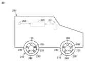
図1は、本実施の形態による状態判定装置が搭載される車両200を模式的に示す図である。車両200は、通信端末201と、スタートスイッチ202と、制御装置205と、複数の車輪210とを備える。Figure 1 is a schematic diagram of a
複数の車輪210の各々は、ホイール220と、ホイール220に取り付けられるタイヤ230とを含む。Each of the
各車輪210のホイール220は、5つのナット240により車両200の車体(より詳しくはホイールハブ)に取り付けられている。なお、各車輪210のナット240の個数は5つに限定されるものではない。The
各車輪210を車体に取り付ける5つのナット240のうちの1つには、第1センサ装置100が配置される。なお、第1センサ装置100は、各車輪210を車体に取り付ける5つのナット240のうちの2つ以上に配置されていてもよい。The
第1センサ装置100は、たとえば、ナット240に取り付けられるキャップの内表面に取り付けられて(接着されて)いる。第1センサ装置100は、ナット240の緩みの有無を判定し、その判定結果を無線送信するように構成される。第1センサ装置100は、ナット緩み検出装置の一例である。The
図2は、第1センサ装置100(ナット緩み検出装置)の構成の一例を示す図である。図2には、第1センサ装置100がナット240の緩みの有無を加速度センサを用いて判定する場合の構成が例示されている。なお、第1センサ装置100がナット240の緩みを判定するために用いられるセンサは、必ずしも加速度センサに限定されず、たとえば磁気センサであってもよい。Figure 2 is a diagram showing an example of the configuration of the first sensor device 100 (nut loosening detection device). Figure 2 shows an example of the configuration when the
第1センサ装置100は、加速度センサ1と、信号処理部2と、通信部3と、電源部4とを備える。加速度センサ1は、たとえば、ホイール220の回転軸に対して直交する平面において互いに直交する2つの軸(X軸およびY軸)の各々の加速度を検出する。The
通信部3は、車両200の通信端末201(図1参照)との間で無線通信可能に構成される。通信部3は、信号処理部2の処理結果を示す信号を車両200の通信端末201(図1参照)に無線送信する。The
電源部4は、加速度センサ1、信号処理部2、および、通信部3の各々に電力を供給する。電源部4は、たとえばボタン電池などで実現することができる。The
信号処理部2は、図示されないCPU等のプロセッサと、メモリと、入出力バッファとを含んで構成される。The
信号処理部2は、ナット240の状態に関する情報を含む信号(以下「第1信号」ともいう)を、通信部3から車両200の通信端末201に周期的に無線送信する。第1センサ装置100が無線送信可能な第1信号の種類には、機能信号と、正常信号と、異常信号とが含まれる。The
機能信号は、第1センサ装置100が車輪210から脱落しておらずに正常に機能していることを車両200の制御装置205に通知する目的で、第1センサ装置100が送信する信号である。信号処理部2は、機能信号を定期的に通信部3から車両200の通信端末201に無線送信する。The function signal is a signal transmitted by the
正常信号は、ナット240の緩みが無いことが検出されたことを示す信号である。異常信号は、ナット240の緩みが有ることが検出されたことを示す信号である。信号処理部2は、加速度センサ1からの信号(X軸方向の加速度およびY軸方向の加速度)に基づいてナット240が緩んでいるか否かを判定する判定処理を周期的に実行する。判定処理によってナット240の緩みが無いことが検出された場合、信号処理部2は、正常信号を通信部3から車両200の通信端末201に無線送信する。一方、判定処理によってナット240の緩みが有ることが検出された場合、信号処理部2は、異常信号を通信部3から車両200の通信端末201に無線送信する。The normal signal is a signal indicating that it has been detected that the
図1に戻って、各車輪210のホイール220には、第1センサ装置100に加えて、第2センサ装置150が配置される。第2センサ装置150は、たとえば、タイヤ230に空気を吸入するためのバルブと一体的に形成される。第2センサ装置150は、車輪210のタイヤ230の空気圧を監視し、その監視結果を無線送信するように構成される。第2センサ装置150は、タイヤ圧監視装置の一例である。Returning to FIG. 1, in addition to the
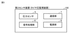
図3は、第2センサ装置150(タイヤ圧監視装置)の構成の一例を示す図である。第2センサ装置150は、圧力センサ5と、信号処理部6と、通信部7と、電源部8とを備える。圧力センサ5は、タイヤ230の空気圧を検出する。Figure 3 is a diagram showing an example of the configuration of the second sensor device 150 (tire pressure monitoring device). The
通信部7は、車両200の通信端末201(図1参照)との間で無線通信可能に構成される。通信部7は、信号処理部6の処理結果を示す信号を車両200の通信端末201(図1参照)に周期的に無線送信する。The
電源部8は、圧力センサ5、信号処理部6、および通信部7の各々に電力を供給する。電源部8は、たとえばボタン電池などで実現することができる。The
信号処理部6は、図示されないCPU等のプロセッサと、メモリと、入出力バッファとを含んで構成される。The
信号処理部6は、タイヤ230の空気圧に関する情報を含む信号(以下「第2信号」ともいう)を、通信部7から車両200の通信端末201に無線送信する。信号処理部6は、圧力センサ5からの信号に基づいてタイヤ230の空気圧が基準値よりも低下しているか否か(タイヤ230がパンクしているか否か)を監視し、その監視結果を第2信号として無線送信する。The
なお、上述の第1センサ装置100および第2センサ装置150は、互いに単独(スタンドアローン)で作動する。Note that the
図1に戻って、通信端末201は、各車輪210の第1センサ装置100および第2センサ装置150との間で無線通信可能に構成される。Returning to FIG. 1, the
スタートスイッチ202は、ユーザが車両200の制御システムを起動して車両200を走行させる場合に、ユーザによって押されるボタンである。車両200の制御システムが停止している状態でユーザがスタートスイッチ202を押すと、制御装置205を含む車両200の制御システムが起動され、車両200が走行可能な状態となる。The
制御装置205は、図示されないCPU(Central Processing Unit)等のプロセッサと、メモリと、入出力バッファとを含んで構成される。The
制御装置205は、各車輪210の第1センサ装置100(ナット緩み検出装置)から受信した第1信号に基づいて、車輪210の脱落の予兆の有無を判定する。車輪210の脱落の予兆があると判定された場合には、その旨をユーザに通知する処理(たとえば図示しないディスプレイに車輪210の脱落の予兆がある旨を表示する処理)を実行する。The
また、制御装置205は、車輪210の第2センサ装置150(タイヤ圧監視装置)から受信した第2信号に基づいて、タイヤ230の減圧(パンク)の有無を監視する。タイヤ230が減圧(パンク)していると判定された場合には、その旨をユーザに通知する処理(たとえば図示しないディスプレイにタイヤ230が減圧(パンク)している旨を表示する処理)を実行する。The
<第1信号と第2信号との混信の防止>
上述のような構成を有する車両200において、第1センサ装置100(ナット緩み検出装置)の無線通信に使用される周波数帯と、第2センサ装置150(タイヤ圧監視装置)の無線通信に使用される周波数帯とが同一であると、混信する恐れがある。混信が生じると、車両200の制御装置205が第1センサ装置100からの第1信号および第2センサ装置150からの第2信号を正確に受信できないことが懸念される。 <Prevention of interference between first and second signals>
In the
特に、タイヤ圧監視システム(TPMS)においては、法規要件によって、車両200の制御システム起動時あるいは走行開始時からの一定時間(たとえば数分間)内にタイヤの減圧をユーザに通知することが要求される場合がある。また、タイヤ圧監視システムには、車両の制御システム起動後あるいは走行開始後に、タイヤ圧監視装置が取り付けられているタイヤの位置を自動で判定するオートロケーション機能を有するものがある。オートロケーション機能を有する場合には、車両の制御システム起動時あるいは走行開始時からの一定時間内に、オートロケーション機能によってタイヤ圧監視装置が取り付けられるタイヤ位置を確定した後に、タイヤの減圧をユーザに通知する必要がある。それにも関わらず、タイヤ圧監視装置からの電波送信中に、タイヤ圧監視装置の電波と同じ周波数帯の電波がナット緩み検出装置からも送信されると、双方の電波が混信してしまい、車両の走行開始時からの一定時間内にタイヤ圧監視装置の取り付け位置の確定、およびユーザへのタイヤ減圧の通知を適切に行えなくなることが懸念される。In particular, in a tire pressure monitoring system (TPMS), legal requirements may require that tire pressure reduction be notified to the user within a certain time (e.g., several minutes) from when the control system of the
そこで、本実施の形態による第1センサ装置100(ナット緩み検出装置)は、車両200の走行開始後の一定時間(たとえば数分間)は、第2センサ装置150(タイヤ圧監視装置)の無線通信を優先すべく、第1信号の通信制限を行なう。具体的には、第1センサ装置100は、第1信号の送信内容を最小限の内容に制限する。たとえば、第1信号の種類のうち、上述の機能信号および正常信号については、緊急性が低いため送信しないようにする。その一方、ナット240の緩みが有ることを示す異常信号については、緊急性が高いため、走行開始後の一定時問以内であってもバースト的に送信する。すなわち、第1センサ装置100は、走行開始後の一定時間以内に送信可能な第1信号の種類を異常信号のみに限定する。Therefore, the first sensor device 100 (nut loosening detection device) according to this embodiment restricts communication of the first signal for a certain period of time (e.g., several minutes) after the
図4は、第1センサ装置100の信号処理部2が実行する処理手順の一例を示すフローチャートである。このフローチャートは、予め定められた条件が成立する毎に繰り返し実行される。Figure 4 is a flowchart showing an example of a processing procedure executed by the
信号処理部2は、タイヤ230の停止が継続している時間がしきい時間よりも長いか否かを判定する(ステップS10)。この判定は、車両200の制御システムの作動中に車両200が信号待ち等で一時的に停車している状態であるのか、それとも、ユーザが既に降車して車両200の制御システムが停止中であるのかを推定するための処理である。したがって、しきい時間は、比較的長い時間(たとえば数時間程度)に設定される。The
第1センサ装置100は、車両200の制御装置205からの情報を取得しない限り、車両200の制御システムの状態を把握することはできない。そこで、第1センサ装置100の信号処理部2は、加速度センサ1の出力に基づいてタイヤ230の状態を把握し、その結果で車両200の制御システムの状態を推定する。具体的には、タイヤ230の停止中には加速度センサ1の出力が変化しないことに鑑み、信号処理部2は、加速度センサ1の出力が変化していない時間(=タイヤ230の停止が継続している時間)がしきい時間よりも長い場合に、車両200の制御システムが停止中であると推定する。The
タイヤ230の停止が継続している時間がしきい時間よりも短い場合(ステップS10においてNO)、信号処理部2は、第1信号の無線通信制限を行なわない(ステップS50)。具体的には、信号処理部2は、緊急性が高い異常信号の送信を許容しつつ、緊急性が低い機能信号および正常信号については無線送信をしないようにする。これにより、車両200が信号待ち等で一時的に停車している状態である場合には、その後に車両200の走行が開始されたとしても、第1信号の無線通信制限を行なわないようにすることができる。If the time during which the
タイヤ230の停止が継続している時間がしきい時間よりも長い場合(ステップS10においてYES)、車両200の制御システムが停止中であると推定されるため、信号処理部2は、タイヤ230が回転し始めたか否かを判定する(ステップS20)。この判定は、ユーザが車両200の制御システムを起動させて車両200の走行を開始したか否かを判定するための処理である。たとえば、信号処理部2は、加速度センサ1の出力が変化した場合に、タイヤ230が回転し始めた、すなわち車両200の走行が開始されたと判定する。If the time during which the
タイヤ230が停止状態のままである場合(ステップS20においてNO)、車両200の制御システムが未だ停止状態であると推定されるため、信号処理部2は、第1信号の無線通信制限を行なわない(ステップS50)。具体的には、信号処理部2は、緊急性が高い異常信号だけでなく、緊急性が低い機能信号および正常信号についても、無線送信を許容する。If the
タイヤ230が回転し始めた場合(ステップS20においてYES)、ユーザが車両200の制御システムを起動させて車両200の走行を開始したと推定されるため、信号処理部2は、第1信号の無線通信制限を行なう(ステップS30)。具体的には、信号処理部2は、緊急性が高い異常信号の送信を許容しつつ、緊急性が低い機能信号および正常信号については無線送信をしないようにする。When the
次いで、信号処理部2は、タイヤ230が回転し始めてから一定時間(たとえば数分間)が経過したか否かを判定する(ステップS40)。タイヤ230が回転し始めてから一定時間が経過していない場合(ステップS40においてNO)、信号処理部2は、処理をステップS30に戻し、第1信号の無線通信制限を継続する。これにより、ユーザが車両200の制御システムを起動させて車両200の走行を開始した時から一定時間が経過するまでの期間は、第1信号の無線通信が制限されるため、第1信号と第2信号との混信が防止され易くなる。その結果、第2センサ装置150(タイヤ圧監視装置)の無線通信を優先させることができる。Next, the
一方、タイヤ230が回転し始めてから一定時間が経過している場合(ステップS40においてYES)、車両200の走行開始後の一定期間内における第2センサ装置150の無線通信が既に行なわれていると推定されるため、信号処理部2は、第1信号の無線通信制限を解除する(ステップS50)。すなわち、信号処理部2は、緊急性が高い異常信号だけでなく、緊急性が低い機能信号および正常信号についても、無線送信を許容する。On the other hand, if a certain amount of time has passed since the
以上のように、本実施の形態による第1センサ装置100(ナット緩み検出装置)は、車両200の走行開始後の一定時間は、第1信号の通信制限を行なう。具体的には、第1センサ装置100は、第1信号の種類のうち、緊急性が高い異常信号の送信を許容しつつ、緊急性が低い機能信号および正常信号については無線送信をしないようにする。その結果、第1センサ装置100(ナット緩み検出装置)の無線通信に使用される周波数帯と、第2センサ装置150(タイヤ圧監視装置)の無線通信に使用される周波数帯とが同一であっても、車両200の走行開始後の一定時間は、第1センサ装置100からの第1信号と第2センサ装置150からの第2信号との混信を防止し易くすることができる。As described above, the first sensor device 100 (nut loosening detection device) according to this embodiment restricts communication of the first signal for a certain period of time after the
なお、上述の実施の形態においては、車両走行開始後の一定時間内における第1信号の通信制限の一例として、第1信号の送信種類を制限する、すなわち緊急性の高い異常信号の送信のみを許容し、緊急性が低い機能信号および正常信号を無線送信をしない例について説明した。しかしながら、第1信号の通信制限の手法はこれに限定されない。たとえば、第1信号の通信制限の手法として、第1信号の送信種類を制限することに代えてあるいは加えて、第1信号の送信頻度を制限するようにしてもよい。たとえば、車両走行開始後の一定時間は、緊急性が低い機能信号および正常信号の送信頻度を、車両走行開始後の一定時間経過後よりも大幅に下げるようにしてもよい。このようにしても、車両走行開始後の一定時間内において、第1センサ装置100からの第1信号と第2センサ装置150からの第2信号との混信を防止し易くすることができる。In the above embodiment, as an example of communication restriction of the first signal within a certain time after the vehicle starts running, an example has been described in which the type of transmission of the first signal is restricted, that is, only the transmission of an abnormal signal with high urgency is permitted, and the functional signal and normal signal with low urgency are not wirelessly transmitted. However, the method of communication restriction of the first signal is not limited to this. For example, as a method of communication restriction of the first signal, instead of or in addition to restricting the type of transmission of the first signal, the frequency of transmission of the first signal may be restricted. For example, for a certain time after the vehicle starts running, the frequency of transmission of the functional signal and normal signal with low urgency may be significantly reduced compared to after a certain time has elapsed after the vehicle starts running. Even in this way, interference between the first signal from the
今回開示された実施の形態はすべての点で例示であって制限的なものではないと考えられるべきである。本開示の範囲は上記した説明ではなくて特許請求の範囲によって示され、特許請求の範囲と均等の意味および範囲内でのすべての変更が含まれることが意図される。The embodiments disclosed herein should be considered to be illustrative and not restrictive in all respects. The scope of the present disclosure is indicated by the claims rather than the above description, and is intended to include all modifications within the meaning and scope of the claims.
以上に説明した例示的な実施の形態およびその変形例は、以下の態様の具体例である。The exemplary embodiment and its variations described above are specific examples of the following aspects:
(第1項) 本開示による車輪の状態判定装置は、タイヤを含む車輪を車体に締結する締結部材の状態に関する情報を含む第1信号を無線送信する第1センサ装置と、タイヤの空気圧に関する情報を含む第2信号を無線送信する第2センサ装置と、第1センサ装置から受信した第1信号に基づく処理、および、第2センサ装置から受信した第2信号に基づく処理を行なう制御装置とを備える。第1センサ装置は、車輪が回転し始めてから所定時間が経過するまでは、車輪が回転し始めてから所定時間が経過した後に比べて、第1信号の送信を制限する。(Paragraph 1) The wheel condition determination device according to the present disclosure includes a first sensor device that wirelessly transmits a first signal including information regarding the condition of a fastening member that fastens a wheel, including a tire, to a vehicle body, a second sensor device that wirelessly transmits a second signal including information regarding the air pressure of the tire, and a control device that performs processing based on the first signal received from the first sensor device and processing based on the second signal received from the second sensor device. The first sensor device limits transmission of the first signal until a predetermined time has elapsed since the wheel started to rotate, compared to after the predetermined time has elapsed since the wheel started to rotate.
上記の態様によれば、車輪が回転し始めてから所定時間が経過するまでは、第1センサ装置による第1信号の送信が制限される。そのため、第1センサ装置の無線通信に使用される周波数帯と、第2センサ装置の無線通信に使用される周波数帯とが同一であっても、車輪が回転し始めてから(車両が走行し始めてから)所定時間が経過するまでの時間において、第1センサ装置からの第1信号と第2センサ装置からの第2信号との混信を防止し易くすることができる。According to the above aspect, the transmission of the first signal by the first sensor device is restricted until a predetermined time has elapsed since the wheel starts to rotate. Therefore, even if the frequency band used for the wireless communication of the first sensor device and the frequency band used for the wireless communication of the second sensor device are the same, it is possible to easily prevent interference between the first signal from the first sensor device and the second signal from the second sensor device during the time from when the wheel starts to rotate (when the vehicle starts to move) until the predetermined time has elapsed.
(第2項) 第1項に記載の状態判定装置において、第1センサ装置が無線送信可能な第1信号の種類には、第1センサ装置が正常に機能していることを示す機能信号と、締結部材の緩みが無いことを示す正常信号と、締結部材の緩みが有ることを示す異常信号とが含まれる。第1センサ装置は、車輪が回転し始めてから所定時間が経過するまでは、機能信号および正常信号の送信を制限しつつ異常信号の送信を許容し、車輪が回転し始めてから所定時間が経過した後は、機能信号、正常信号および異常信号の送信を許容する。(Clause 2) In the state determination device described in
上記の態様によれば、車輪が回転し始めてから所定時間が経過するまでは、第1信号の3つの種類(機能信号、正常信号、異常信号)のうち、緊急性の低い機能信号および正常信号の送信は制限されるが、緊急性の高い異常信号の送信は許容される。そのため、車輪の回転開始後(車両の走行開始後)の所定時間において、第1信号と第2信号との混信を防止し易くしつつ、締結部材の緩みが有ることを制御装置に通知することができる。According to the above aspect, during the period from when the wheel starts to rotate until a predetermined time has elapsed, of the three types of first signals (function signal, normal signal, and abnormal signal), the transmission of the less urgent function signal and normal signal is restricted, but the transmission of the more urgent abnormal signal is permitted. Therefore, during the predetermined period after the wheel starts to rotate (after the vehicle starts to move), it is possible to notify the control device that the fastening member is loose, while making it easier to prevent interference between the first signal and the second signal.
(第3項) 第1または2項に記載の状態判定装置において、第1センサ装置は、締結部材に加わる加速度を検出する加速度センサと、制御部と、無線送信部とを含む。制御部は、加速度センサの出力に基づいて車輪が回転し始めたか否かを判定し、車輪が回転し始めたと判定された時点から所定時間が経過するまで、第1信号の送信を制限する。(Clause 3) In the state determination device described in
上記の態様によれば、第1センサ装置が、他の装置からの情報を得なくても、加速度センサの出力に基づいて車輪が回転し始めたこと(車両が走行し始めたこと)を検出して第1信号の送信を制限することができる。According to the above aspect, the first sensor device can detect that the wheels have started to rotate (that the vehicle has started to move) based on the output of the acceleration sensor and limit the transmission of the first signal, without obtaining information from another device.
(第4項) 第3項に記載の状態判定装置において、制御部は、加速度センサの出力に基づいてタイヤの停止期間が所定期間継続したか否かを判定し、タイヤの停止期間が所定期間継続したと判定された後に、車輪が回転し始めたか否かを判定し、車輪が回転し始めたと判定された時点から所定時間が経過するまで、第1信号の送信を制限する。(4) In the state determination device described in 3, the control unit determines whether the tire has been stopped for a predetermined period based on the output of the acceleration sensor, and after it is determined that the tire has been stopped for the predetermined period, it determines whether the wheel has started to rotate, and restricts the transmission of the first signal until a predetermined time has elapsed from the time it is determined that the wheel has started to rotate.
上記の態様によれば、車両が信号待ち等で一時的に停車している状態から車輪が回転し始めるような状況においては、第1信号の送信制限を行わないようにすることができる。According to the above aspect, in a situation where the wheels start to rotate after the vehicle is temporarily stopped while waiting for a traffic light, etc., it is possible to avoid restricting the transmission of the first signal.
1 加速度センサ、2,6 信号処理部、3,7 通信部、4,8 電源部、5 圧力センサ、100 第1センサ装置、150 第2センサ装置、200 車両、201 通信端末、202 スタートスイッチ、205 制御装置、210 車輪、220 ホイール、230 タイヤ、240 ナット。1 Acceleration sensor, 2, 6 Signal processing unit, 3, 7 Communication unit, 4, 8 Power supply unit, 5 Pressure sensor, 100 First sensor device, 150 Second sensor device, 200 Vehicle, 201 Communication terminal, 202 Start switch, 205 Control device, 210 Wheel, 220 Wheel, 230 Tire, 240 Nut.
Claims (4)
Translated fromJapanese前記タイヤの空気圧に関する情報を含む第2信号を無線送信する第2センサ装置と、
前記第1センサ装置から受信した前記第1信号に基づく処理、および、前記第2センサ装置から受信した前記第2信号に基づく処理を行なう制御装置とを備え、
前記第1センサ装置は、前記車輪が回転し始めてから所定時間が経過するまでは、前記車輪が回転し始めてから前記所定時間が経過した後に比べて、前記第1信号の送信を制限する、車輪の状態判定装置。 a first sensor device that wirelessly transmits a first signal including information regarding a state of a fastening member that fastens a wheel including a tire to a vehicle body;
a second sensor device configured to wirelessly transmit a second signal including information regarding the tire pressure;
a control device that performs processing based on the first signal received from the first sensor device and processing based on the second signal received from the second sensor device;
A wheel condition determination device, wherein the first sensor device limits transmission of the first signal until a predetermined time has elapsed since the wheel starts to rotate, compared to after the predetermined time has elapsed since the wheel starts to rotate.
前記第1センサ装置は、
前記車輪が回転し始めてから所定時間が経過するまでは、前記機能信号および前記正常信号の送信を制限しつつ前記異常信号の送信を許容し、
前記車輪が回転し始めてから前記所定時間が経過した後は、前記機能信号、前記正常信号および前記異常信号の送信を許容する、請求項1に記載の車輪の状態判定装置。 types of the first signal that the first sensor device can wirelessly transmit include a function signal indicating that the first sensor device is functioning normally, a normal signal indicating that the fastening member is not loosened, and an abnormality signal indicating that the fastening member is loosened;
The first sensor device is
restricting the transmission of the function signal and the normal signal while permitting the transmission of the abnormal signal until a predetermined time has elapsed since the wheel starts to rotate;
2. The wheel condition determination device according to claim 1, wherein the transmission of the function signal, the normal signal and the abnormal signal is permitted after the predetermined time has elapsed since the wheel started to rotate.
前記締結部材に加わる加速度を検出する加速度センサと、
制御部と、
無線送信部とを含み、
前記制御部は、
前記加速度センサの出力に基づいて前記車輪が回転し始めたか否かを判定し、
前記車輪が回転し始めたと判定された時点から前記所定時間が経過するまで、前記第1信号の送信を制限する、請求項1または2に記載の車輪の状態判定装置。 The first sensor device is
an acceleration sensor for detecting an acceleration applied to the fastening member;
A control unit;
a wireless transmitter unit;
The control unit is
determining whether the wheel has started to rotate based on an output of the acceleration sensor;
3. The wheel condition determining device according to claim 1, wherein transmission of the first signal is restricted until the predetermined time has elapsed from the time when it is determined that the wheel has started to rotate.
前記加速度センサの出力に基づいて前記タイヤの停止期間が所定期間継続したか否かを判定し、
前記タイヤの停止期間が所定期間継続したと判定された後に、前記車輪が回転し始めたか否かを判定し、
前記車輪が回転し始めたと判定された時点から前記所定時間が経過するまで、前記第1信号の送信を制限する、請求項3に記載の車輪の状態判定装置。
The control unit is
determining whether the tire has been stopped for a predetermined period of time based on an output of the acceleration sensor;
After it is determined that the stop period of the tire has continued for a predetermined period, it is determined whether the wheel has started to rotate;
4. The wheel condition determining device according to claim 3, wherein transmission of the first signal is restricted until the predetermined time has elapsed from the time when it is determined that the wheel has started to rotate.
Priority Applications (1)
| Application Number | Priority Date | Filing Date | Title |
|---|---|---|---|
| JP2022191521AJP2024078908A (en) | 2022-11-30 | 2022-11-30 | Wheel condition determination device |
Applications Claiming Priority (1)
| Application Number | Priority Date | Filing Date | Title |
|---|---|---|---|
| JP2022191521AJP2024078908A (en) | 2022-11-30 | 2022-11-30 | Wheel condition determination device |
Publications (1)
| Publication Number | Publication Date |
|---|---|
| JP2024078908Atrue JP2024078908A (en) | 2024-06-11 |
Family
ID=91391276
Family Applications (1)
| Application Number | Title | Priority Date | Filing Date |
|---|---|---|---|
| JP2022191521APendingJP2024078908A (en) | 2022-11-30 | 2022-11-30 | Wheel condition determination device |
Country Status (1)
| Country | Link |
|---|---|
| JP (1) | JP2024078908A (en) |
Cited By (1)
| Publication number | Priority date | Publication date | Assignee | Title |
|---|---|---|---|---|
| US12298568B2 (en) | 2017-06-28 | 2025-05-13 | Corning Research & Development Corporation | Fiber optic connectors and multiport assemblies including retention features |
- 2022
- 2022-11-30JPJP2022191521Apatent/JP2024078908A/enactivePending
Cited By (1)
| Publication number | Priority date | Publication date | Assignee | Title |
|---|---|---|---|---|
| US12298568B2 (en) | 2017-06-28 | 2025-05-13 | Corning Research & Development Corporation | Fiber optic connectors and multiport assemblies including retention features |
Similar Documents
| Publication | Publication Date | Title |
|---|---|---|
| EP1336511B1 (en) | Transmitter of tire condition monitoring apparatus and tire condition monitoring apparatus with this transmitter | |
| JP4752661B2 (en) | Transmitter and tire pressure detecting device having the same | |
| JP4270284B2 (en) | Wheel state monitoring system and wheel state detection device | |
| JP6747415B2 (en) | Tire pressure detection device | |
| JP6027261B1 (en) | Wheel positioning device | |
| WO2013187016A1 (en) | Wheel location detector device and tire air pressure detector device comprising same | |
| JP2012140069A (en) | Tire air pressure monitoring device | |
| WO2016208056A1 (en) | Tire state sensing device and tire state monitoring device | |
| JP2024078908A (en) | Wheel condition determination device | |
| WO2020075776A1 (en) | Tire pressure monitoring system | |
| US11390125B2 (en) | Wheel registration apparatus and tire pressure monitoring system including the same | |
| EP2524154B1 (en) | Manual transmission neutral switch diagnostic and movement prevention method and system for a vehicle | |
| CN116141881A (en) | Tire Position Judgment System | |
| WO2012023379A1 (en) | Sensor unit and method for registering sensor unit for tire air pressure monitoring system | |
| US7308823B2 (en) | Tire pressure control system for a vehicle | |
| JP2013525174A (en) | Method and monitoring system for monitoring the pressure in a wheel tire | |
| JP4747956B2 (en) | Wheel condition monitoring device | |
| JP3951947B2 (en) | Tire pressure detector | |
| JP3952868B2 (en) | Automotive air pressure alarm device | |
| JP6407807B2 (en) | Tire pressure detection device, tire pressure monitoring device | |
| JP2023066796A (en) | Tire abnormality determination system | |
| JP6027043B2 (en) | Tire condition monitoring device | |
| JP5898059B2 (en) | Tire sensor unit | |
| US12159491B2 (en) | Retightening notification apparatus | |
| JP2006327324A (en) | Tire condition monitoring device |
Legal Events
| Date | Code | Title | Description |
|---|---|---|---|
| A621 | Written request for application examination | Free format text:JAPANESE INTERMEDIATE CODE: A621 Effective date:20250521 |