JP2024065079A - Method and apparatus for power delivery in a wireless power system - Patents.com - Google Patents
Method and apparatus for power delivery in a wireless power system - Patents.comDownload PDFInfo
- Publication number
- JP2024065079A JP2024065079AJP2023184331AJP2023184331AJP2024065079AJP 2024065079 AJP2024065079 AJP 2024065079AJP 2023184331 AJP2023184331 AJP 2023184331AJP 2023184331 AJP2023184331 AJP 2023184331AJP 2024065079 AJP2024065079 AJP 2024065079A
- Authority
- JP
- Japan
- Prior art keywords
- power
- receiver
- transmitter
- beacon
- focused
- Prior art date
- Legal status (The legal status is an assumption and is not a legal conclusion. Google has not performed a legal analysis and makes no representation as to the accuracy of the status listed.)
- Pending
Links
Images


Classifications
- H—ELECTRICITY
- H02—GENERATION; CONVERSION OR DISTRIBUTION OF ELECTRIC POWER
- H02J—CIRCUIT ARRANGEMENTS OR SYSTEMS FOR SUPPLYING OR DISTRIBUTING ELECTRIC POWER; SYSTEMS FOR STORING ELECTRIC ENERGY
- H02J50/00—Circuit arrangements or systems for wireless supply or distribution of electric power
- H02J50/20—Circuit arrangements or systems for wireless supply or distribution of electric power using microwaves or radio frequency waves
- H02J50/23—Circuit arrangements or systems for wireless supply or distribution of electric power using microwaves or radio frequency waves characterised by the type of transmitting antennas, e.g. directional array antennas or Yagi antennas
- H—ELECTRICITY
- H02—GENERATION; CONVERSION OR DISTRIBUTION OF ELECTRIC POWER
- H02J—CIRCUIT ARRANGEMENTS OR SYSTEMS FOR SUPPLYING OR DISTRIBUTING ELECTRIC POWER; SYSTEMS FOR STORING ELECTRIC ENERGY
- H02J50/00—Circuit arrangements or systems for wireless supply or distribution of electric power
- H02J50/20—Circuit arrangements or systems for wireless supply or distribution of electric power using microwaves or radio frequency waves
- H02J50/27—Circuit arrangements or systems for wireless supply or distribution of electric power using microwaves or radio frequency waves characterised by the type of receiving antennas, e.g. rectennas
- H—ELECTRICITY
- H02—GENERATION; CONVERSION OR DISTRIBUTION OF ELECTRIC POWER
- H02J—CIRCUIT ARRANGEMENTS OR SYSTEMS FOR SUPPLYING OR DISTRIBUTING ELECTRIC POWER; SYSTEMS FOR STORING ELECTRIC ENERGY
- H02J50/00—Circuit arrangements or systems for wireless supply or distribution of electric power
- H02J50/80—Circuit arrangements or systems for wireless supply or distribution of electric power involving the exchange of data, concerning supply or distribution of electric power, between transmitting devices and receiving devices
- H—ELECTRICITY
- H02—GENERATION; CONVERSION OR DISTRIBUTION OF ELECTRIC POWER
- H02J—CIRCUIT ARRANGEMENTS OR SYSTEMS FOR SUPPLYING OR DISTRIBUTING ELECTRIC POWER; SYSTEMS FOR STORING ELECTRIC ENERGY
- H02J50/00—Circuit arrangements or systems for wireless supply or distribution of electric power
- H02J50/90—Circuit arrangements or systems for wireless supply or distribution of electric power involving detection or optimisation of position, e.g. alignment
- H—ELECTRICITY
- H04—ELECTRIC COMMUNICATION TECHNIQUE
- H04B—TRANSMISSION
- H04B5/00—Near-field transmission systems, e.g. inductive or capacitive transmission systems
- H04B5/70—Near-field transmission systems, e.g. inductive or capacitive transmission systems specially adapted for specific purposes
- H04B5/72—Near-field transmission systems, e.g. inductive or capacitive transmission systems specially adapted for specific purposes for local intradevice communication
- H—ELECTRICITY
- H04—ELECTRIC COMMUNICATION TECHNIQUE
- H04B—TRANSMISSION
- H04B5/00—Near-field transmission systems, e.g. inductive or capacitive transmission systems
- H04B5/70—Near-field transmission systems, e.g. inductive or capacitive transmission systems specially adapted for specific purposes
- H04B5/79—Near-field transmission systems, e.g. inductive or capacitive transmission systems specially adapted for specific purposes for data transfer in combination with power transfer
Landscapes
- Engineering & Computer Science (AREA)
- Computer Networks & Wireless Communication (AREA)
- Power Engineering (AREA)
- Signal Processing (AREA)
- Variable-Direction Aerials And Aerial Arrays (AREA)
- Charge And Discharge Circuits For Batteries Or The Like (AREA)
- Mobile Radio Communication Systems (AREA)
- Near-Field Transmission Systems (AREA)
Abstract
Description
Translated fromJapanese本明細書における記述は、電力伝送システムおよびバッテリ充電器、特に電力を必要とするデバイスを給電するためのマイクロ波伝送によるワイヤレス電力伝送のための方法およびシステムに関する。The description herein relates to power transmission systems and battery chargers, and in particular to methods and systems for wireless power transmission via microwave transmission to power devices requiring power.
(相互参照および利益の主張)
本出願は、あらゆる目的のために本出願に完全に記載されているかのように参照により本明細書に組み込まれる、2022年10月28日に出願された「METHOD AND APPARATUS FOR POWER DELIVERY IN A WIRELESS POWER SYSTEM」という名称の米国特許仮出願第63/420,373号からの優先権を主張する。(Cross-reference and claim of benefit)
This application claims priority from U.S. Provisional Patent Application No. 63/420,373, entitled "METHOD AND APPARATUS FOR POWER DELIVERY IN A WIRELESS POWER SYSTEM," filed on October 28, 2022, which is incorporated by reference herein for all purposes as if fully set forth herein.
多くの可搬型電子デバイスは、バッテリによって給電される。再充電可能なバッテリは、しばしば、従来の乾電池の交換コストを回避し、貴重な資源を保全するために使用される。しかし、従来の再充電可能なバッテリ充電器でバッテリを再充電することは、使用可能でないことも便利でないこともある交流(AC)電力アウトレットへのアクセスを必要とする。したがって、バッテリ充電器のための電力を電磁放射から導出することが望ましいであろう。Many portable electronic devices are powered by batteries. Rechargeable batteries are often used to avoid the replacement costs of traditional dry cell batteries and to conserve valuable resources. However, recharging the battery with a traditional rechargeable battery charger requires access to an alternating current (AC) power outlet, which may not be available or convenient. Therefore, it would be desirable to derive power for the battery charger from electromagnetic radiation.
太陽電池式バッテリ充電器が知られているが、太陽電池は高価であり、かなり大きな容量のバッテリを充電するために、太陽電池の大きなアレイが必要とされ得る。AC電力の商用電源から離れた場所においてバッテリ充電器に電力を供給する別の潜在的な電磁エネルギー源は、太陽電池式衛星から導出されマイクロ波ビームによって地球に伝送され得る、または携帯電話のトランスミッタおよび他のトランスミッタからの周囲の無線周波数エネルギーから導出され得るマイクロ波エネルギーである。しかし、マイクロ波伝送による電力の効率的な送達には、この目的のために専用の陸上マイクロ波電力トランスミッタを使用することを妨げているいくつかの問題が伴う。Solar-powered battery chargers are known, but solar cells are expensive and large arrays of solar cells may be required to charge batteries of significant capacity. Another potential source of electromagnetic energy for powering battery chargers at locations remote from commercial sources of AC power is microwave energy, which may be derived from solar-powered satellites and transmitted to Earth by microwave beams, or may be derived from ambient radio frequency energy from mobile phone transmitters and other transmitters. However, efficient delivery of power by microwave transmission involves several problems that have prevented the use of dedicated terrestrial microwave power transmitters for this purpose.
電磁(EM)信号の単一源電力伝送を仮定すると、EM信号は、距離rにわたって大きさが1/r2に比例して減少する。したがって、EMトランスミッタからの大きな距離において受信電力は、伝送された電力の小部分である。Assuming a single-source power transmission of an electromagnetic (EM) signal, the EM signal decreases in magnitude proportional to 1/r2 over distance r. Thus, at large distances from the EM transmitter, the received power is a small fraction of the transmitted power.
受信される信号の電力を増大するために、伝送電力はブーストされなければならないことになる。信号がEMトランスミッタから3センチメートルで効率的に受信されると仮定すると、3メートルという有用な距離にわたって同じ信号電力を受信することは、伝送される電力を10,000倍にブーストすることを必要とすることになる。そのような電力伝送は、エネルギーの大部分が、伝送されるが所期のデバイスによって受信されず、生体組織にとって危険なものとなる可能性があり、すぐ近くの大部分の電子デバイスと干渉する可能性が非常に高く、熱として放散され得るので、無駄が多い。To increase the power of the received signal, the transmitted power would have to be boosted. Assuming that the signal is efficiently received 3 centimeters from the EM transmitter, receiving the same signal power over a useful distance of 3 meters would require boosting the transmitted power by a factor of 10,000. Such power transmission is wasteful, as most of the energy is transmitted but not received by the intended device, potentially dangerous to living tissue, very likely to interfere with most electronic devices in the immediate vicinity, and may be dissipated as heat.
指向性アンテナを使用することには、いくつかの課題があり、それらのいくつかは、それをどこに向けるか知っていること、それを追跡するために必要とされる機械デバイスはノイズが多く信頼できない、および伝送の見通し線内のデバイスについて干渉を創出することである。Using a directional antenna has several challenges, some of which are knowing where to point it, the mechanical devices needed to track it are noisy and unreliable, and it creates interference for devices within the line of sight of the transmission.
指向性電力伝送は、概して、電力伝送効率を向上させるために正しい方向で信号を向けることができるようにデバイスの場所を知っていることを必要とする。しかし、デバイスが位置特定されているときでさえ、その経路内、または受信するデバイスの近くの物体の反射および干渉により効率的な伝送は保証されない。Directional power transmission generally requires knowing the location of the device so that the signal can be pointed in the correct direction to improve power transmission efficiency. However, even when the device is located, efficient transmission is not guaranteed due to reflections and interference from objects in the path or near the receiving device.
したがって、前述の問題を解決するワイヤレス電力伝送システムが望まれている。Therefore, there is a need for a wireless power transmission system that can solve the above problems.
1つまたは複数の実施形態によれば、方法が提供される。この方法は、トランスミッタおよびレシーバを含むワイヤレス電力システムにおける電力送達のためのものである。この方法は、トランスミッタによって伝送された集束電力(focused power)をレシーバによって受信すること、およびレシーバによって、集束電力の無線周波数(RF)電力レベルを直接測定することを含む。この方法は、集束電力の電力レベルが閾値を超えるかどうか決定すること、および電力レベルが閾値を超える、または超えないことに基づいて1つまたは複数の動作を実施することを含む。According to one or more embodiments, a method is provided for power delivery in a wireless power system including a transmitter and a receiver. The method includes receiving, by a receiver, focused power transmitted by the transmitter, and directly measuring, by the receiver, a radio frequency (RF) power level of the focused power. The method includes determining whether a power level of the focused power exceeds a threshold, and performing one or more actions based on the power level exceeding or not exceeding the threshold.
1つまたは複数の実施形態によれば、方法が提供される。この方法は、トランスミッタおよびレシーバを含むワイヤレス電力システムにおける電力送達のためのものである。この方法は、トランスミッタによって、レシーバからビーコンを受信すること、およびトランスミッタによって、ビーコン受信信号強度インジケータ(RSSI)を測定するためにビーコンのRSSIデータを解析することを含む。この方法は、ビーコンRSSIが閾値を超えるかどうか決定すること、およびビーコンRSSIが閾値を超える、または超えないことに基づいて1つまたは複数の動作を実施することを含む。According to one or more embodiments, a method is provided for power delivery in a wireless power system including a transmitter and a receiver. The method includes receiving, by the transmitter, a beacon from the receiver, and analyzing, by the transmitter, the beacon received signal strength indicator (RSSI) data to measure a beacon RSSI. The method includes determining whether the beacon RSSI exceeds a threshold, and performing one or more actions based on the beacon RSSI exceeding or not exceeding the threshold.
これらおよび他の特徴は、以下の明細書および図面をさらに検討すれば容易に明らかになる。These and other features will become readily apparent upon further consideration of the following specification and drawings.
同様の符号は、添付の図面を通じて一貫して対応する特徴を示す。Similar reference numbers refer to corresponding features consistently throughout the accompanying drawings.
1つまたは複数の実施形態によれば、電力伝送システムおよびバッテリ充電器が本明細書に記載されている。電力伝送システムおよびバッテリ充電器は、電力を必要とするデバイスを給電するためのマイクロ波伝送によるワイヤレス電力伝送のための方法および/またはシステムを含むことができる。According to one or more embodiments, a power transmission system and a battery charger are described herein. The power transmission system and the battery charger may include a method and/or system for wireless power transmission via microwave transmission to power a device requiring power.
1つまたは複数の実施形態によれば、ワイヤレス電力伝送のための方法および/またはシステムは、マイクロ波エネルギーを介して電子/電気デバイスにワイヤレス充電を提供する、および/または主電力を供給するためのシステム(本明細書においてと称される電力伝送システム)である。マイクロ波エネルギーは、ビーコンデバイス(たとえば、ビーコントランスミッタを含む電力レシーバ)からビーコン信号を受信したことに応答して、1つまたは複数の適応フェーズドマイクロ波アレイエミッタを有する電力トランスミッタによって、ある場所に集束される。充電対象のビーコンデバイス内のレクテナが、マイクロ波エネルギーを受信および整流し、それをバッテリ充電のために、および/または主電力のために使用する。According to one or more embodiments, a method and/or system for wireless power transmission is a system for providing wireless charging and/or primary power to electronic/electrical devices via microwave energy (referred to herein as a power transmission system). Microwave energy is focused to a location by a power transmitter having one or more adaptive phased microwave array emitters in response to receiving a beacon signal from a beacon device (e.g., a power receiver including a beacon transmitter). A rectenna in the beacon device to be charged receives and rectifies the microwave energy and uses it for battery charging and/or for primary power.
1つまたは複数の実施形態によれば、初期セットアップ中、電力伝送システムの電力トランスミッタ(Tx)と、電力伝送システム(たとえば、ビーコンデバイスまたはビーコントランスミッタを含む電力レシーバ)のレシーバ(Rx)との間の距離は未知である。この距離を、Tx/Rx距離と称することができる。Txは、低電力状態で給電開始する。低電力状態は、電力伝送システムの整流器を損傷する危険性がないことを確実にする。たとえば、低電力状態は、Rxによって見られたとき1メートルで2W未満のRF電力になる始動(「低」)電力レベルを含む。低電力状態の正確な電力レベルは、電力伝送システムのアプリケーションおよび/または設計に従って必要に応じて構成可能とすること/調整することができる。According to one or more embodiments, during initial setup, the distance between the power transmitter (Tx) of the power transmission system and the receiver (Rx) of the power transmission system (e.g., a beacon device or a power receiver including a beacon transmitter) is unknown. This distance can be referred to as the Tx/Rx distance. The Tx starts powering in a low power state. The low power state ensures that there is no risk of damaging the rectifier of the power transmission system. For example, the low power state includes a start-up ("low") power level that results in less than 2 W of RF power at 1 meter as seen by the Rx. The exact power level of the low power state can be configurable/adjusted as needed according to the application and/or design of the power transmission system.
1つまたは複数の実施形態によれば、受信された低電力レベルが確立された後で、Txは、最適な電力レベルが達成されるように伝送される電力を増大させることができる。たとえば、充電対象のビーコンデバイスは、レクテナにおける受信されたビーム信号強度を、サイドチャネルを介して電力源にレポートする。別の例として、充電対象のビーコンデバイスは、レクテナにおける受信されたビーム信号強度を、同じ電力周波数を介して電力源にレポートする。この情報は、最大マイクロ波エネルギーが充電対象のビーコンデバイスによってレポートされるまで、マイクロ波アレイエミッタの伝送する位相を調整するために電力伝送システムによって使用される。According to one or more embodiments, after a low received power level is established, the Tx can increase the transmitted power such that an optimal power level is achieved. For example, the beacon device being charged reports the received beam signal strength at the rectenna to the power source via a side channel. As another example, the beacon device being charged reports the received beam signal strength at the rectenna to the power source via the same power frequency. This information is used by the power transmission system to adjust the transmitting phase of the microwave array emitter until maximum microwave energy is reported by the beacon device being charged.
1つまたは複数の実施形態によれば、アレイエレメントを、充電されるビーコンデバイスから較正信号を受信するように設定することができる。各アレイエレメントは、受信された較正信号から位相情報を検出/レポートすることができる。その後、各アレイエレメントは、そのエレメントについて検出された位相を、充電されるビーコンデバイスに戻される伝送位相に対するガイドとして使用する。According to one or more embodiments, the array elements can be configured to receive a calibration signal from the beacon device being charged. Each array element can detect/report phase information from the received calibration signal. Each array element then uses the detected phase for that element as a guide for the transmission phase back to the beacon device being charged.
たとえば平坦な2次元アレイによって引き起こされるミラー焦点は、マイクロ波アレイエミッタを実質的に非均一、非同一平面的にして物理的に構成することによって最小化される。For example, mirror focal spots caused by flat two-dimensional arrays are minimized by physically configuring the microwave array emitters to be substantially non-uniform and non-coplanar.
本明細書に記載の本方法およびシステムの1つまたは複数の技術的効果、利点、および/または利益は、回路損傷、RF暴露レベル、および/または回路を過熱することという1つまたは複数の問題を解決することを含む。これに関して、本方法およびシステムは、過剰に高い受信されるRF電力レベルによる電力レシーバにおける潜在的な回路損傷(たとえば、RF整流器における)を防止し、RF暴露レベルを最小化し、電力トランスミッタにおける電力消費を削減し、それにより熱的な問題(たとえば、回路の過熱)を低減する。したがって、本方法およびシステムの動作は、必然的にそれに根ざし、マイクロ波エネルギーを介して電子/電気デバイスにワイヤレス充電を提供すること、および/または主電力を供給することを実装および改良する。One or more technical effects, advantages, and/or benefits of the methods and systems described herein include solving one or more problems of circuit damage, RF exposure levels, and/or overheating circuits. In this regard, the methods and systems prevent potential circuit damage (e.g., in RF rectifiers) in the power receiver due to excessively high received RF power levels, minimize RF exposure levels, and reduce power consumption in the power transmitter, thereby reducing thermal issues (e.g., overheating of circuits). Thus, the operation of the methods and systems is necessarily rooted in, implementing and improving the provision of wireless charging and/or primary power to electronic/electrical devices via microwave energy.
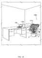
図1A~図1Bに示されているように、本発明は、マイクロ波エネルギーを介して電子/電気デバイス、たとえばラップトップコンピュータ102などにワイヤレス充電を提供する、および/または主電力を供給するためのシステム100aまたは代替のシステム100bを含む。システム100aまたはシステム100bのいずれかにおいて、電力伝送グリッド101aまたは代替の電力伝送グリッド101b(たとえば、物体S上に配置されている)が、電力アウトレットO内にプラグ接続される電力コードPを介して交流(AC)商用電源から動作電力を得ることができる。マイクロ波伝送周波数は、好ましくは、好適な波長を有する使用可能なFCC規制外周波数である。波長がフェーズドアレイ101aまたは代替のフェーズドアレイ101bの分解能を制限する可能性があるので、システムが動作し得る他の周波数の選択肢を限定しないが、好ましい周波数は、5.8GHz(5.17cm波長)であると決定されており、これは、部屋、講堂などの規模での距離にわたって、ラップトップ、携帯電話、PDAなどのデバイスへの電力伝送に適している。1A-1B, the present invention includes a system 100a or
図1A~図3Cに示されているように、マイクロ波エネルギーは、1つまたは複数の適応フェーズドマイクロ波アレイエミッタ204、すなわちアンテナまたは放射器に接続された電力源300によって充電対象のデバイス上に集束される。本発明によれば、適応フェーズドマイクロ波アレイエミッタ204からのマイクロ波エネルギーは、デバイスの場所を知っている必要なくデバイス上に集束され得る。図1A、図1B、および図3A~図3Bに示されているように、充電対象のデバイス102内の、好ましくは非常に効率的なレクテナ340(レクテナは、マイクロ波エネルギーを直流(DC)電気に直接変換する整流アンテナであり、そのようなデバイスは当技術分野で知られており、本明細書にはこれ以上記載されていない)が、マイクロ波エネルギーを受信および整流し、制御ロジック350によって決定されて、充電を介してバッテリ370を充電するために、および/または主電力をデバイス102に供給するためにそれを使用する。第1の実施形態では、ワイヤレス電力源100aと充電対象のデバイス102内の電力レシーバ330bとの間に通信チャネルが、電力を運ぶために使用される周波数以外の周波数で開かれる。As shown in Figures 1A-3C, microwave energy is focused on the device to be charged by a
充電対象のデバイス102は、通信チャネル110aの上でレクテナ340において受信されたビーム信号強度を、電力レシーバ330b内の通信デバイス360のトランスミッタセクションからの信号を介して、システム100aの電力トランスミッタ330a内の通信デバイス320のレシーバセクションに中継する。この情報は、最大マイクロ波エネルギービーム301がアレイ110aによって放射されたと充電対象のデバイス102によってレポートされるまで、給電開始、給電停止、およびマイクロ波アレイエミッタノード204の伝送する位相を調整するために、システム100aの制御ロジック310によって使用される。The
所望の伝送周波数の単一源に接続された各エミッタ204は、□/2の倍数である特定の位相差と共に信号を伝送することができる。□/2位相増分は例示的なものにすぎず、他の位相増分、たとえば□/4、□/8、□/16、および他の増分が可能である。好ましくは、エミッタ204を所望の位相に合わせてオフまたはオンすることができることを除いて、電力は調整されない。Each
図2A~図2Bに示されているように、垂直ケーブルおよび水平ケーブルが各アレイノード204で交差する。この構成は、アレイ101aまたはアレイ101bのいずれかに当てはまる。垂直ケーブル202内では、ワイヤ210はゼロ位相給電ラインである。ワイヤ212は1/2□位相給電ラインであり、ワイヤ209は垂直制御ラインである。同様に、水平ケーブル200内では、ワイヤ214は□位相給電ラインである。ワイヤ216は3/2□位相給電ラインであり、ワイヤ211は水平制御ラインである。制御ライン209および211は、任意の所与のノード204上でどの位相がアクティブであるか制御するために、コントローラ310に接続されることが可能である。単一のアンテナ制御は、チップ206上にあることができ、一方、実際のノード放射器またはアンテナ208は、ノード204の幾何中心を囲む円形のエレメントとして形成され得る。単一のコントローラまたは複数のコントローラのいずれかが、電力伝送グリッドのうちの1つまたは複数を制御し得ることを理解されたい。2A-2B, vertical and horizontal cables cross at each
1つまたは複数の実施形態による、システム100aのための制御ロジック310の例示的なアルゴリズム(たとえば、方法380)が図3Cに示されている。方法380は、ブロック381で始まり、電力レシーバ330は、通信チャネル110aを使用し、その存在を近くの任意のトランスミッタ330aに宣言することができる。ブロック382では、電力トランスミッタ330aは、その存在を通信チャネル110a上で通信し、アンテナ208またはノード204のうちの1つだけと伝送を開始し得る。ブロック383では、電力レシーバ330bは、通信チャネル110a上でかすかな信号を受信したことを確認応答し得る。ブロック384では、電力トランスミッタ330aは、ゼロのデフォルト位相で別のアンテナ208またはノード204をオンに切り替え、信号強度について通信チャネル110aの上でレシーバ330bに尋ね得る。ブロック385では、電力レシーバ330bは、受信された信号が以前より高い、同じ、または以前より低いことを示す信号を返信し得る。ブロック386では、信号が以前より低い、または以前と同じである場合、コントローラ310は、ノード204にその位相を1/2□増大させ、別の信号強度伝送を要求し得る。矢印387によって示されているように、ブロック385および386は、すべての位相について繰り返される。ブロック388では、信号強度の増大が観察されない場合には、その特定のノード204がオフに切り替えられ、別のノードが方法380において使用される(たとえば、方法380は、矢印389によって示されているようにブロック384に戻り、ブロック384、385、386は、すべてのエミッタノードが使用状態になるまで繰り返される)。An exemplary algorithm (e.g., method 380) of the
別の例では、ブロック386は、0、1/2□、および5□/4ラジアンを含む3相サイクルにわたって位相を増大させることを含み得る。このようにして、正弦曲線全体の近似形状が決定され得る。したがって、ピーク電力の位相角が決定され得る。また、同調されたアンテナを追加するとき、次に追加されるアンテナの受信電力は、受信される総電力の小さい割合にすぎないことがある。したがって、第2のアンテナを追加することは、電力を4倍に増大し得、一方、101番目のアンテナを追加することは、電力に2%追加し得、1001番目は、受信される総電力に0.2%追加し得る。これは、テストされているアンテナからの実際の利得/損失を検出することを困難にし得る。したがって、少しのアンテナだけがテストサイクル中に給電開始され得、テストされている各アンテナについての位相が記憶され得る。全アレイの位相が決定した後で、すべてのエレメントが、電力を送達するためにオンに切り替えられ得る。In another example, block 386 may include increasing the phase over a three-phase cycle including 0, 1/2□, and 5□/4 radians. In this way, the approximate shape of the entire sinusoid may be determined. Thus, the phase angle of the peak power may be determined. Also, when adding tuned antennas, the received power of the next antenna added may only be a small percentage of the total power received. Thus, adding a second antenna may increase the power by a factor of four, while adding a 101th antenna may add 2% to the power, and a 1001st may add 0.2% to the total power received. This may make it difficult to detect the actual gain/loss from the antenna being tested. Thus, only a few antennas may be powered up during a test cycle, and the phase for each antenna being tested may be stored. After the phase of the entire array is determined, all elements may be switched on to deliver power.
代替として、伝送される電力におけるすべてのアンテナが、おそらくはそれらの位相をそれらの現在の値周りでわずかに移動し、受信された信号に対する影響を検出することによって再同調され得る。それが一方向で改善する場合(たとえば、位相を進ませる、または遅らせる)、位相は、どちらの側にも改善がなくなるまで引き続きサイクル/増分され得る。これは、大きなアレイについて受信電力レベルの変化を検出できることに依存することになり、そうでない場合、アレイ全体をオフに切り替え、位相を最初から再確立することが必要になり得る。Alternatively, all antennas in the transmitted power could be retuned, perhaps by moving their phase slightly around their current value and detecting the effect on the received signal. If it improves in one direction (e.g., advances or retards the phase), the phase could continue to be cycled/incremented until there is no improvement on either side. This would depend on being able to detect the change in received power levels for a large array, otherwise it may be necessary to switch off the entire array and re-establish the phase from scratch.
第2の実施形態では、図2Bおよび図3Bに最も明瞭に示されているように、各アレイエレメントまたはノード204を、電力受信システム330bにおける較正トランスミッタ460から較正信号を受信するように設定することができる。各アレイエレメントまたはノード204は、そのノード204において検出された受信された較正信号を、データライン303を介して制御ロジック310に送ることができる。その後、コントローラ310、コントローラ206、または組合せでの両コントローラは、各アレイエレメントまたはノード204を、最適化された電力伝送301を電力レシーバ330bに送り返すために、伝送位相としてそのエレメントについて検出された位相に設定し得る。実施形態100aおよび100bの両方において、最初に充電対象のデバイス102に通信する必要なくアレイが電力を特定の場所または「ホットスポット」に伝送することを可能にするために、構成メモリデバイスがコントローラロジック310と動作可能に通信し得る。この特徴は、充電対象のデバイス102が通信チャネル110aまたは110bを確立するための予備の電力を有していないとき、充電対象のデバイス102に電力伝送301を送る際に有用である。In a second embodiment, as shown most clearly in FIGS. 2B and 3B, each array element or
代替として、第2の実施形態は、レシーバおよびすべてのトランスミッタアンテナにおける双方向機能、たとえばトランシーバにおけるものを利用するために以下のように動作し得る。コントローラが、電力レシーバ(すなわち、充電対象のデバイス)からビーコン信号を受信するようにすべてのトランシーバを準備し得る。次いで、充電対象のデバイスは、充電対象のデバイスと電力トランスミッタとの間のすべての開いた経路を横断するビーコン信号(たとえば、アレイとレシーバとの間の、それらのクロックを同期させるための、たとえばワイヤレス通信を介した、フェーズドアレイと同じ周波数であり得る較正信号)を送出する。電力トランスミッタにおける受信された信号は、電力トランスミッタ内の各アンテナに着地するレシーバとトランスミッタのアンテナとの間のすべての開いた経路の和に等しく、各経路の和は、すべての特定の電力トランスミッタアンテナにおいて合計して特定の電力レベルおよび位相になる。Alternatively, the second embodiment may operate as follows to take advantage of the bidirectional capabilities in the receiver and all transmitter antennas, e.g., in the transceivers. The controller may prepare all transceivers to receive a beacon signal from the power receiver (i.e., the device to be charged). The device to be charged then sends out a beacon signal (e.g., a calibration signal, which may be at the same frequency as the phased array, e.g., via wireless communication between the array and the receiver to synchronize their clocks) that traverses all open paths between the device to be charged and the power transmitter. The received signal at the power transmitter is equal to the sum of all open paths between the receiver and the transmitter antennas that land on each antenna in the power transmitter, and the sum of each path sums up to a particular power level and phase at every particular power transmitter antenna.
トランスミッタアレイにおける各アンテナは、入来信号を内部信号と比較し、受信された位相を検出する。受信された位相がすべてのトランスミッタのアンテナによって確立された後、各アンテナは、その完全電力で受信された位相の複素共役において伝送し返す。Each antenna in the transmitter array compares the incoming signal to an internal signal to detect the received phase. After the received phase is established by all transmitter antennas, each antenna transmits back at its full power at the complex conjugate of the received phase.
さらに、アレイの上記の同調は、すべての可能な経路を考慮する(たとえば、アレイとレシーバとの間に直接開いた経路があること、またはレシーバが環境内で滑らかに直線運動で移動することは仮定されない)ので、環境の構成に対する変更は、レシーバが移動されること、または電力トランスミッタアレイの物理的な構成が変更されることに等しくなり得る。したがって、アレイの頻繁な再同調が常に必要とされ得る(たとえば、毎秒10回以上)。Furthermore, since the above tuning of the array considers all possible paths (e.g., it is not assumed that there is a direct open path between the array and the receiver, or that the receiver moves in a smooth linear motion within the environment), changes to the configuration of the environment may be equivalent to the receiver being moved, or the physical configuration of the power transmitter array being changed. Thus, frequent retuning of the array may be constantly required (e.g., 10 or more times per second).
アンテナアレイを再同調することは、レシーバのビーコン信号を「リッスン」するために、送られる電力をシャットオフすることを必要とするので、アレイに給電するために使用することができたはずの時間が失われ得る。したがって、アレイは、レシーバにおける電力レベルが著しく変化しないとき、レシーバへの電力送達を最大にするために、再同調の頻度を低減し得る。レシーバにおける電力受信が降下したとき、アレイは、レシーバ電力が再び安定化するまで更新の頻度を増大し得る。非常に高い頻度の再同調は、有用性を越えて電力移送の効率を低下させ得るので、同調の頻度に対する特定の制限が、たとえば、最小10tps(毎秒の同調数)から最大500tpsでセットアップされ得る。Because retuning the antenna array requires shutting off the power sent to "listen" to the receiver's beacon signal, time that could have been used to power the array may be lost. Thus, the array may reduce the frequency of retuning to maximize power delivery to the receiver when the power level at the receiver does not change significantly. When the power received at the receiver drops, the array may increase the frequency of updates until the receiver power stabilizes again. Since very frequent retuning may reduce the efficiency of power transfer beyond usefulness, specific limits on the frequency of tuning may be set up, for example, a minimum of 10 tps (tunings per second) to a maximum of 500 tps.
代替として、数(n)のアンテナの同調は、以下のように実施され得る。n個のアンテナすべてが、オフに切り替えられ得る。次いで、n個のアンテナのうちの1つがオンにされ、他のn個のアンテナのそれぞれを同調するための参照としてオンのままにされる。次いで、n個のアンテナの残りのそれぞれがオンにされ、それらの最適な位相が記録され、次いでそれらがオフにされる。このシーケンスがn番目のアンテナに対して実施されるとき、すべてのアンテナがそれらのそれぞれの最適な位相でオンにされる。Alternatively, tuning of a number (n) of antennas may be performed as follows: All n antennas may be switched off. Then one of the n antennas is turned on and left on as a reference for tuning each of the other n antennas. Then each of the remaining n antennas is turned on, their optimal phases are recorded, and then they are turned off. When this sequence is performed for the nth antenna, all antennas are turned on at their respective optimal phases.
移動するレシーバを有する第1の実施形態に関して、トランスミッタアンテナのすべてが、たとえば、それらの位相をそれらの現在の値周りでわずかに移動し、受信された信号に対する影響を検出することによって再同調されることを必要とする。それが一方向で改善する場合、位相をサイクル/増分することが、どちらの側にも改善がなくなるまで続く。これは、大きなアレイについて受信電力レベルの変化を検出できることに依存し得、そうでない場合、アレイ全体をオフに切り替え、位相を最初から再確立することが必要になり得る。For the first embodiment with a moving receiver, all of the transmitter antennas would need to be retuned, for example by moving their phase slightly around their current value and detecting the effect on the received signal. If it improves in one direction, cycling/incrementing the phase continues until there is no improvement on either side. This may depend on being able to detect the change in received power levels for large arrays, otherwise it may be necessary to switch off the entire array and re-establish the phase from scratch.
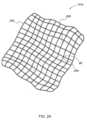
例示的なアレイ101aまたは101bは、1辺あたり約1メートルの30×30のグリッドネットとすることができ、ワイヤの各交差点が単一の伝送アンテナまたはノード204を有する。好ましくは、アレイグリッド101aまたは101bは、可撓性/柔軟な材料製である。グリッド材料の可撓性は、たとえば平坦な2次元アレイ、および離散的な位相差を有する平坦な規則正しく配置されたアレイにおいて通常生じる盲点によって引き起こされるミラー焦点を最小化するために、ユーザがマイクロ波アレイエミッタグリッド101aまたは101bを実質的に非均一、非同一平面的にして、すなわち平坦でなく広げて、物理的に構成することを可能にする。図1A~図1Bに示されているように、アレイ101aまたはアレイ101bのいずれかは、好ましくは、非均一、非同一平面の構成を提供するために、支持構造物、たとえば鉢植えSに垂れ掛けることができるように十分に可撓性である。An
このようにして、フェーズドアンテナは指向性であり、それにより受信デバイス102において受信することができる強め合う位相の(constructively phased)ビーム信号を介して利得を創出するので、逆2乗の法則への挑戦に成功する。さらに、フェーズドアレイ、たとえば101aまたは101bの使用は、より扱いにくい見苦しいデバイス、たとえば物理的な指向性アンテナ、すなわち皿形、八木などを使用する必要性をなくす。さらに、電力伝送過程の効率に起因して、環境に害を及ぼすことも他のどこかに位置するデバイスと干渉を引き起こすこともないように、電磁(EM)信号がその強度の大部分を至る所に広げるのではなく受信デバイス近くで有することができるように、低い電力が伝送のために使用され得る。In this way, phased antennas successfully challenge the inverse square law because they are directional, thereby creating gain via constructively phased beam signals that can be received at the receiving
信号が受信され、その電力が使用可能になった後、バッテリ370、電力貯蔵キャパシタなどを充電するためにアンテナから来る約5.80GHzのAC電流をDC電流に変換する処理が、そのタスクが可能な低電圧整流器で行われる。これらの整流器は、受信された信号と同じ位相で、したがってレクテナ340の整流器部分内で使用されるダイオードの電圧降下を克服する点までその電力を強める、小面積ショットキダイオードに基づくものとすることも5.80GHz発信回路を用いた共振を利用することもできる。複数のビーム構成をシミュレートするために、アレイをタイムシェアリングすることによって、またはアンテナの位相同士を重畳することによって、複数のデバイスが充電され得ることに留意されたい。After the signal is received and the power is available, the process of converting the approximately 5.80 GHz AC current coming from the antenna to a DC current for charging the
上記の充電機構は、トランスミッタとレシーバが互いに通信するとき動作する。しかし、通信するための電力がないレシーバを充電するための方法もまた、有益なものとなり得る。これを達成するために、周期的な電力伝送バーストを受信することになる1つまたは複数の場所が確立され得る。The charging mechanism described above works when the transmitter and receiver communicate with each other. However, a way to charge a receiver that does not have power to communicate can also be useful. To accomplish this, one or more locations can be established that will receive periodic power transmission bursts.
バッテリ電力のないデバイスを充電するための一例では、ビーコンデバイスまたはリサレクタ(図示せず)が周期的な電力伝送バーストを受信する、またはユーザによる要求あり次第受信するための場所内に配置され得る。ビーコンデバイスは、たとえばビーコン信号を伝送することによって電力伝送グリッドと通信し、電力伝送グリッドは、そのビーコン信号の位相構成を、周期的な電力伝送バースト(たとえば、10分毎の1秒バースト、または10分毎の1秒バーストを伴う1分毎の0.1秒バースト)を伝送するための場所として認識する。ビーコンデバイスから伝送されるビーコン信号は、電力伝送グリッドに到達する前に様々な媒体を通じて反射および/または屈折され得る。したがって、複数のビーコン信号が電力伝送グリッドによって受信され得る。電力伝送グリッドが1つまたは複数のビーコン信号を受信するとき、ビーコンデバイスの場所から電力伝送グリッドへの開いた経路が確立され得る。In one example for charging a device without battery power, a beacon device or researctor (not shown) may be placed within a location to receive periodic power transmission bursts or upon request by a user. The beacon device communicates with the power transmission grid, for example by transmitting a beacon signal, and the power transmission grid recognizes the phase configuration of the beacon signal as a location for transmitting periodic power transmission bursts (e.g., a 1 second burst every 10 minutes, or a 0.1 second burst every minute followed by a 1 second burst every 10 minutes). The beacon signal transmitted from the beacon device may be reflected and/or refracted through various media before reaching the power transmission grid. Thus, multiple beacon signals may be received by the power transmission grid. When the power transmission grid receives one or more beacon signals, an open path may be established from the location of the beacon device to the power transmission grid.
次いで、電力伝送グリッドは、伝送されたビーコン信号の波形を回復するためにビーコン信号を集約し得る。この回復された波形から、次いで電力伝送グリッドは、たとえば、ビーコンデバイスによって確立された場所において電力バーストを提供するために回復された波形の逆波形として、電力伝送バーストを伝送することができる。一実施形態では、逆波形は、ビーコンデバイスから受信された波形の複素共役または数学的に等価な変換をとることによって決定され得る。周期的な電力伝送バーストを受信するための場所が確立された後、ビーコンデバイスをオフにすることができる。The power transmission grid may then aggregate the beacon signal to recover the waveform of the transmitted beacon signal. From this recovered waveform, the power transmission grid may then transmit a power transmission burst, for example, as an inverse waveform of the recovered waveform to provide a power burst at a location established by the beacon device. In one embodiment, the inverse waveform may be determined by taking a complex conjugate or a mathematically equivalent transform of the waveform received from the beacon device. After a location has been established to receive periodic power transmission bursts, the beacon device may be turned off.
次いで、バッテリ電力のない充電対象のデバイス102を、上記の充電処理を受けるために電力伝送グリッドと通信するための十分な電力を有するまで、それが周期的な電力伝送バーストを受信することになるその場所において配置することができる。次いで、デバイスをその場所から離すことができる。The device to be charged 102 without battery power can then be placed at the location where it will receive periodic power transmission bursts until it has sufficient power to communicate with the power transmission grid to undergo the charging process described above. The device can then be removed from the location.
充電対象のデバイス102がある場所から別の場所に移動された、または電力伝送グリッドが移動された後、電力伝送グリッドは、充電対象のデバイス102への最良の伝送電力を確立するために、それ自体再同調し得る(たとえば、伝送アンテナを再位置合わせする)。この再同調は、デバイス102が電力の降下をレポートしたことに応答して、または規則的な間隔(たとえば、1ミリ秒~10秒)で行われ得る。しかし、規則的な間隔は、電力の降下がないにもかかわらず定期的に再同調し続けながら、信号電力がレシーバによっていかに十分に維持されるかに応じて短縮されても延長されてもよい。After the
トランスミッタアンテナは、様々な形状および設計で構成および使用され得る「フェーズドワイヤ」の長い帯状体を創出するように、回路を単一のチップ内に含め、チップをワイヤでデイジーチェーン接続する形態をもとり得る。「位相制御」チップの帯状体を通じて数千のアンテナおよび関連のコントローラで複雑なアレイを構築すると、チップ間のワイヤは、チップを共通のコントローラに接続するデータ経路として働き得、一方同時に、ワイヤはそれら自体、伝送/受信アンテナとしても作用し得る。各チップは、そこから出てアンテナとして作用する多くのワイヤを有し得る。各アンテナには、アドレス(たとえば、a、b、cおよび他の指定)が与えられ得、チップが各アンテナの位相を互いに独立に制御することを可能にする。さらに、アレイの同調がアンテナの場所および配置にかかわりないので、ワイヤは、使用可能な空間に応じてあらゆる種類の配置で構成され得る。Transmitter antennas may also take the form of circuitry contained within a single chip, with the chips daisy-chained with wires to create long swaths of "phased wire" that can be configured and used in a variety of shapes and designs. When building complex arrays with thousands of antennas and associated controllers across a swath of "phased" chips, the wires between chips may act as data paths connecting the chips to a common controller, while at the same time, the wires may themselves act as transmit/receive antennas. Each chip may have many wires coming out of it that act as antennas. Each antenna may be given an address (e.g., a, b, c, and other designations), allowing the chip to control the phase of each antenna independently of one another. Furthermore, since tuning of the array is independent of the location and placement of the antennas, the wires may be configured in all sorts of arrangements depending on the available space.
アンテナチップコントローラは短いワイヤを通じて接続されるので、ワイヤは、いくつかのやり方でアンテナとして利用され得る。たとえば、ワイヤそれら自体は、発振器および/もしくは増幅器によって駆動され得、またはシールドがワイヤ周りで使用され得、シールドそれ自体はアンテナとして駆動および使用され、したがって多層アレイ内で通信ワイヤが信号を遮蔽するのを防止する。Since the antenna chip controllers are connected through short wires, the wires can be utilized as antennas in several ways. For example, the wires themselves can be driven by oscillators and/or amplifiers, or a shield can be used around the wires, which itself is driven and used as an antenna, thus preventing the communication wires from shielding the signals in a multi-layer array.
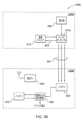
図4は、代替の第1の実施形態トランスミッタのブロック図である。トランスミッタは、制御ロジック410、移相器420(N個)、信号発生器/乗算器430、増幅器440(N個)、および(N)アンテナ450を含むアンテナコントローラ400であり得る。アンテナコントローラ400は、共通のバス上で、すべてのアンテナコントローラを制御する単一のコントローラから、または前のアンテナコントローラ400から電力およびベース周波数制御信号ならびに他のコマンドおよび通信信号を受信する。たとえば、電力信号が、トランスミッタ400の電源(図示せず)によって受信され得、一方、ベース周波数制御信号が、信号発生器/乗算器430によって受信され得、通信信号およびコマンドが、制御ロジック410によって受信され得る。前の各アンテナコントローラ400が電力およびベース周波数制御信号を提供する場合、これらの信号を搬送するバスは、次のアンテナコントローラ400に続き得る。制御ロジック410は、増幅器440の位相を調整させるように移相器420を制御し得る。信号発生器/乗算器は、たとえば10MHzで信号をバスから受信し、たとえば2.4GHz、5.8GHz、およびワイヤレス伝送のための他の値までそれを変換する。4 is a block diagram of an alternative first embodiment transmitter. The transmitter may be an
図5は、代替の第2の実施形態トランスミッタのブロック図である。トランスミッタは、制御ロジック510、移相器520(N個)、信号発生器/乗算器530、トランシーバ540(N個)、(N)アンテナ550、位相比較器560(N個)を含むアンテナコントローラ500であり得る。トランシーバ540は、レシーバから較正またはビーコン信号を受信し、その信号を位相比較器560に転送する。位相比較器560は、それらのそれぞれのトランシーバ540の受信された信号の位相を決定し、電力信号を伝送するための最適な位相角を決定する。この情報は、制御ロジック510に提供され、制御ロジック510は次いで、移相器520に(たとえば、受信されたビーコン/較正信号の複素共役で)トランシーバの位相を設定させ、その設定された位相で電力を伝送させる。信号発生器/乗算器530は、アンテナコントローラ400の信号発生器/乗算器430と実質的に同様の機能を実施する。さらに、バス信号は、トランスミッタ400におけるものと同様であり、その信号は、たとえば、トランスミッタ500内の相手方構成要素によって受信される。5 is a block diagram of an alternative second embodiment transmitter. The transmitter may be an
図6は、たとえば図4および図5のアンテナコントローラを制御するためのコントローラ600のブロック図である。コントローラ600は、制御ロジック610、電力源620、アンテナ660に接続された通信ブロック630、アンテナ670に接続されたベース信号クロック640、およびバスコントローラ650を含む。制御ロジック610は、バスコントローラ650を制御し、バスコントローラ650は、M個のバス上でM個のアンテナコントローラ(たとえば、400および500)に信号を伝送する。電力源620は、バスコントローラ650に電力源を提供する。通信ブロック630は、そのそれぞれのアンテナ660を介してレシーバからのデータを送受信する。ベース信号クロック640は、ベース信号を他のコントローラに伝送し、同期のためにレシーバに伝送対象をも送信/受信し得る。1つのコントローラ600がすべてのトランスミッタアンテナを制御するために利用され得、または1つのコントローラ600がアンテナのグループを制御する場合、いくつかのコントローラ600が使用され得る。さらに、それぞれのアンテナを有する別々の通信ブロックおよびベース信号クロックが示されているが、機能は1つのブロック(たとえば、通信ブロック630)内に組み込まれ得ることに留意されたい。6 is a block diagram of a
図7は、第1の実施形態による代替のレシーバ700のブロック図である。レシーバ700は、制御ロジック710、バッテリ720、通信ブロック730および関連のアンテナ760、電力計740、ならびに整流器750および関連のアンテナ770を含む。制御ロジック710は、通信ブロック730からのデータ搬送波周波数上のデータ信号を送受信する。このデータ信号は、上記のサイドチャネルの上で伝送される電力強度信号の形態にあり得る。整流器750は、電力トランスミッタから電力伝送信号を受信し、これは、電力計740を通じて充電のためにバッテリ720に供給される。電力計740は、受信電力信号強度を測定し、制御ロジック710にこの測定結果を提供する。制御ロジック710は、バッテリ720それ自体からバッテリ電力レベルをも受信し得る。7 is a block diagram of an
レシーバ700は、たとえば、アンテナ670を介してコントローラ600にベース周波数信号を伝送させることによってコントローラ600と同期され得る。次いで、レシーバ700は、この信号を使用し、レシーバがコントローラ600に伝送し返すビーコン信号または較正信号を同期し得る。この技法は、複数のコントローラとも利用され得ることにも留意されたい。すなわち、複数の伝送アレイが利用されている場合、コントローラは、コントローラのうちの1つから送られるベース周波数信号を利用することによって互いに同期され得る。The
図8は、第2の実施形態による代替のレシーバ800のブロック図である。レシーバ800は、制御ロジック810、バッテリ820、通信ブロック830および関連のアンテナ870、電力計840、整流器850、ビーコン信号発生器860および関連のアンテナ880、ならびに整流器850またはビーコン信号発生器860を関連のアンテナ890に接続するスイッチ865を含む。整流器850は、電力トランスミッタから電力伝送信号を受信し、これは、電力計840を通じて充電のためにバッテリ820に供給される。電力計840は、受信電力信号強度を測定し、制御ロジック810にこの測定結果を提供する。制御ロジック810は、バッテリ820それ自体からバッテリ電力レベルをも受信し得る。制御ロジック810もまた、通信ブロック830を介して、データ搬送波周波数でデータ信号、たとえばクロック同期のためのベース信号クロックを伝送/受信し得る。ビーコン信号発生器860は、アンテナ880またはアンテナ890のいずれかを使用してビーコン信号または較正信号を伝送する。バッテリ820は、充電されるものとして、またレシーバ800に電力を供給するためのものとして示されているが、レシーバもその電力を整流器850から直接受信し得ることに留意されたい。これは、整流器850が充電電流をバッテリ820に供給することに加えても、または充電を提供することに代えてもよい。また、複数のアンテナの使用は、1つの例示的な実装であり、この構造は、1つの共有されたアンテナに削減され得ることに留意されたい。8 is a block diagram of an
トランスミッタのアンテナ制御回路ならびにレシーバ電力および制御回路は、集積チップ(IC)として構築され得、いくつかの重要な回路構成要素を共有し得るので、2つのチップ機能が単一のチップとして設計され得、異なるパッケージングまたは構成を選ぶことによって、チップはトランスミッタまたはレシーバのいずれかとして機能し得る。すなわち、ある部分が使用可能化または使用不能化された同じチップが伝送アンテナコントローラまたはレシーバコントローラとして利用され得る。これは、2つの異なるチップを構築およびテストするコストを低減し得、またチップ作製コストを節約し得、これらは、かなり大きなものとなり得る。The transmitter antenna control circuitry and the receiver power and control circuitry may be built as an integrated chip (IC) and may share some key circuit components, so that the two chip functions can be designed as a single chip, and by choosing different packaging or configurations, the chip can function as either a transmitter or a receiver. That is, the same chip, with certain parts enabled or disabled, can be utilized as a transmit antenna controller or a receiver controller. This may reduce the cost of building and testing two different chips, and may also save on chip fabrication costs, which may be significant.
上記で論じたように、伝送グリッドの形状は、多くの種類をとり得る。したがって、アンテナのパッキング(packing)は、伝送される電力信号の波長のおよそ2分の1からその波長の数倍に十分近くなる可能性がある。アレイがカーペットの下で平らになる、または屋根裏断熱設備(attic heat insulation)の上に垂れ掛けることを可能にするように、2次元配置にすることができる。たとえば、複数の伝送アンテナを含む複数の幅広ワイヤ(たとえば、2次元アレイの細い帯状体)が使用され得る。これらの幅広ワイヤを、フローリング内、または壁内に設置することができる。あるいは、電力伝送グリッドは、ループアンテナの形態にあることも、任意の他の形状であることも可能である。As discussed above, the shape of the transmission grid can be of many types. Thus, the packing of the antennas can be anywhere from roughly half the wavelength of the transmitted power signal to close enough to several times that wavelength. A two-dimensional arrangement can be used to allow the array to lie flat under carpeting or drape over attic heat insulation. For example, multiple wide wires (e.g., thin strips in a two-dimensional array) containing multiple transmission antennas can be used. These wide wires can be installed in flooring or in walls. Alternatively, the power transmission grid can be in the form of a loop antenna or any other shape.
3次元配置は、最大数のアンテナをパックし得、好都合な形態、たとえばオフィスの天井タイル、ドア、塗装、およびTVに組み込むことができ、したがって、アレイを目に見えない、邪魔にならないものにする。また、グリッドアレイは、前後に重なり合ったいくつかの層で形成され得、より高密度のアンテナを可能にする。この例では、アレイは、最小のミラービームをその後ろに伴う単一の前方ビームを有する「フェーズドボリューム(phased volume)」と同様に作用する。ミラービームは、フェーズドボリュームの厚さが増大するにつれて減少され得る。A three-dimensional arrangement can pack the maximum number of antennas and can be incorporated into convenient forms, such as office ceiling tiles, doors, paint, and TVs, thus making the array invisible and unobtrusive. Also, grid arrays can be formed with several layers stacked back-to-back, allowing for a higher density of antennas. In this example, the array acts similar to a "phased volume" with a single forward beam with a minimal mirror beam behind it. The mirror beam can be reduced as the thickness of the phased volume increases.
すなわち、無指向性アンテナを使用する完璧に平坦なフェーズドアレイは、アレイの平面周りで対称に形成される波面の2つの「イメージ」を創出し得る(たとえば、アレイの両側に自由空間または同一の環境があるとき)。これは、電力送達を減少させる(たとえば、電力の50%がバックプレーンに行く)という望ましくない結果を有し、したがって、移送の効率を減少させる可能性がある。アレイアンテナを非平面形態で配置することは、アンテナがアレイの対称の側をまたいで異なる位相を有することになり、信号を非対称で「非鏡像」のものにするという事実により、3次元アレイの対称設計を有する場合でさえこの対称波面を低減し得る。That is, a perfectly flat phased array using omnidirectional antennas may create two "images" of a wavefront that is symmetrically formed around the plane of the array (e.g., when there is free space or identical environment on both sides of the array). This can have the undesirable result of reducing power delivery (e.g., 50% of the power goes to the backplane) and therefore reducing the efficiency of the transfer. Arranging the array antenna in a non-planar configuration can reduce this symmetric wavefront even with a symmetric design of the three-dimensional array due to the fact that the antennas will have different phases across the symmetric sides of the array, making the signal asymmetric and "non-mirrored".
アレイが特定のレシーバについて位相同調されるとき、その特定のレシーバに到達する信号を創出するために、アレイ内のすべてのアンテナはそれが伝送する特定の位相を有する。以下の技法のうちの1つまたはそれらの組合せによって、2つ以上のレシーバを電力を受信するために構成することができる。When an array is phase-tuned for a particular receiver, every antenna in the array has a particular phase that it transmits to create a signal that reaches that particular receiver. Two or more receivers can be configured to receive power by one or a combination of the following techniques:
一技法では、異なるレシーバ間で電力送達をタイムシェアリングすることが利用され得る。これは、アレイ内のアンテナを1つのレシーバに同調し、次いで次のレシーバに切り替え、各レシーバに等しい(または等しくない)時間量を与えることによって行うことができる。各レシーバに対するアレイの同調は、メモリから、または第2の実施形態技法と同様の処理を使用してアレイを再同調することによって行われ得る。One technique may utilize time sharing of power delivery between different receivers. This may be done by tuning the antennas in the array to one receiver and then switching to the next receiver, giving each receiver an equal (or unequal) amount of time. Tuning the array to each receiver may be done from memory or by retuning the array using a process similar to the second embodiment technique.
別の技法では、複数の電力スポットを創出するためにすべてのアレイアンテナを位相変調することが利用され得る。各アンテナについて、受信された信号は、位相が受信された角度であるベクトルであり、一方、大きさは、受信された信号の電力レベルである。複数のレシーバへの戻り信号を創出するために、伝送の位相は、受信されたベクトルの和の角度であるものとして決定され得る。その大きさの受信された信号を利用し、各アンテナから通常の伝送電力で伝送することは必要でないことがあるが、マルチパス信号を考慮されるときより良好に動作するバイアスされた多焦点信号を創出するために各レシーバからのピークの受信信号電力が発見され得、ベクトル追加は、標準化されたスケールに照らしてベクトルをスケーリングすることによってバイアスされ得る(たとえば、各レシーバからのピーク電力はピーク電力について、マグニチュード1.0のものと考えられ得る)。ベクトルの追加は、各アンテナがより多くの電力を、それがより多くの電力を送達する先の、あるいはより多くの電力を受信する元のレシーバに提供することを確実にし得る。Another technique may utilize phase modulation of all array antennas to create multiple power spots. For each antenna, the received signal is a vector whose phase is the received angle, while the magnitude is the power level of the received signal. To create return signals to multiple receivers, the phase of the transmission may be determined as being the angle of the sum of the received vectors. While it may not be necessary to utilize the magnitude of the received signal and transmit at the normal transmit power from each antenna, the peak received signal power from each receiver may be found to create a biased multi-focal signal that works better when multipath signals are taken into account, and the vector addition may be biased by scaling the vector against a standardized scale (e.g., the peak power from each receiver may be considered to be of magnitude 1.0 for peak power). The vector addition may ensure that each antenna provides more power to the receiver to which it delivers more power, or from which it receives more power.
アンテナ共有が別の技法である。アレイ全体を複数のサブアレイに分割することによって、それぞれがその電力を特定のレシーバに専門に供給し得る。この手法は、アレイが分割されたとき効率的になるほど十分に大きいとき、有益なものとなり得る。Antenna sharing is another technique. By splitting the overall array into multiple subarrays, each can specialize its power to a specific receiver. This approach can be beneficial when the array is large enough to be efficient when split.
別々のアレイが調和して使用され得、この場合、個々のアレイユニットは、指定された「マスタ」ユニットからの連続信号を達成するように、共有された無線(over the air)周波数を使用してそれらのベース信号クロックを同期し、すべての「スレーブ」トランスミッタコントローラユニットがそれらの波形をコヒーレントに加算することを可能にする。これは、別々のアレイが環境内で分散されることを可能にし、複数のアレイを建物、居住区、製造工場、またはオフィス周りに配置するうえでユーザに柔軟性を与える。これらのコントローラのセットアップ中、設置者/管理者は、アレイがいくつ機能停止しようともシステムが使用可能なアレイを使用して働き続けるように、フェールオーバーシーケンスと共にマスタユニットを指定することによって異なるコントローラアレイを互いにリンクさせ得る。たとえば、アレイは、原子時計を使用してそれらを同期することによって設定され得る。すなわち、別々のアレイユニットは、それら別々のアレイユニットが、電力伝送のために使用するための単一の周波数を利用する場合、正確な原子時計(たとえば、1:1010を超える精度)を使用することによって、ベース周波数上で同期することなく働き得る。この場合、これらは、1秒の数分の1で一致することになり、位相/信号のコヒーレント性が維持されることを可能にする。 Separate arrays may be used in unison, where individual array units synchronize their base signal clocks using a shared over the air frequency to achieve a continuous signal from a designated "master" unit, allowing all "slave" transmitter controller units to coherently add their waveforms. This allows separate arrays to be distributed in the environment, giving users flexibility in placing multiple arrays around a building, residential area, manufacturing plant, or office. During the setup of these controllers, the installer/administrator may link different controller arrays together by designating a master unit with a failover sequence so that no matter how many arrays go down, the system continues to work using the available arrays. For example, arrays may be set up by synchronizing them using atomic clocks. That is, separate array units may work without synchronization on the base frequency by using accurate atomic clocks (e.g., accuracy of over 1:1010 ) if the separate array units utilize a single frequency to use for power transmission. In this case, they will match within a fraction of a second, allowing phase/signal coherency to be maintained.
別の電力伝送技法では、トランスミッタは、サイド通信チャネルにおいて通常の信号を送出し得、その存在をすべてのレシーバにブロードキャストする。近くに他のトランスミッタがある場合、合意された周波数のうちの1つを使用すること、または他のトランスミッタの信号を監視することによって信号衝突を回避することを確実にする。これらのブロードキャストアナウンスメントは、毎分数回から毎分1回未満で頻度が変わる可能性がある。レシーバは、その存在をアナウンスする信号を送出し得、トランスミッタは、どれが電力移送に最も適しているか見出すためにネゴシエーションし得る。判断された後、レシーバは、単一のトランスミッタに「ロック」オンする。これは、各トランスミッタが論理(単一のコントローラ)デバイス(複数のリンクされたトランスミッタから構成される可能性がある)として定義されることを必要とし得る。コントローラが、電力エンベロープが変化した(すなわち、レシーバが同じ電力を必要としていない)ことを検出した場合、コントローラは、レシーバが機能停止しないように電力を供給し続け得る。In another power transfer technique, the transmitter may send out a regular signal in a side communication channel, broadcasting its presence to all receivers. If there are other transmitters nearby, it will make sure to avoid signal collisions by using one of the agreed upon frequencies or by monitoring the other transmitters' signals. These broadcast announcements may vary in frequency from a few times per minute to less than once per minute. The receiver may send out a signal announcing its presence, and the transmitters may negotiate to find out which one is best suited for power transfer. Once determined, the receiver "locks" onto a single transmitter. This may require each transmitter to be defined as a logical (single controller) device (which may consist of multiple linked transmitters). If the controller detects that the power envelope has changed (i.e. the receiver is not needing the same power), the controller may continue to provide power so that the receiver does not stall.
別の電力伝送技法では、トランスミッタは、それらが任意の必要とするデバイスに電力を供給するように開かれている、またはそれらが供給すべきデバイスと「ペアリング」されるようにセットアップされる。ペアリングは、トランスミッタの所有者から見て効率に影響を及ぼす可能性がある、隣接するもの同士が意図せず互いに電力を借用するという問題を回避する。トランスミッタは、複数のレシーバに対処するとき、優先順位付けのための階層を確立したい、たとえば最も必要としているデバイスに最初に電力を与えることを望むことがあり、これは、1つまたは複数の事前定義された基準で確立される可能性がある。In another power transfer technique, transmitters are set up so that they are open to supply power to any device that needs it, or are "paired" with the devices they are to supply. Pairing avoids the problem of neighbors unintentionally borrowing power from each other, which can affect efficiency from the transmitter owner's perspective. When dealing with multiple receivers, a transmitter may want to establish a hierarchy for prioritization, for example giving power first to the device that needs it most, which may be established by one or more predefined criteria.
たとえば、基準のいくつかは、以下を含み得る。すなわち、そのデバイスは、その所有者にとって非常に重要なものである(たとえば、玩具に対する携帯電話)、そのデバイスは、通常、必ずしも終日トランスミッタの近くにない(たとえば、携帯電話に比べてTVリモコン)、または、そのデバイスは、直ちに電力を必要とすることが判明しており、そうでなければそれは機能停止することになる。そのようなデバイスは、それらが重要でない電力に到達するまで、他のものより高い優先順位を与えられ得る。あるいは、どのデバイスが最も高い優先順位を得るべきかユーザが判断するユーザカスタマイズ型の優先順位が利用され得る。For example, some of the criteria may include: the device is very important to its owner (e.g., a cell phone versus a toy), the device is not usually near a transmitter all day (e.g., a TV remote control versus a cell phone), or the device is known to require power immediately or it will shut down. Such devices may be given higher priority than others until they reach non-critical power. Alternatively, a user-customized priority may be utilized where the user determines which devices should get the highest priority.
上記の例示的な優先順位付けプリファレンスは、アレイの設置者がくつがえすことができ、システムが所有者/ユーザの優先順位付けで送達していることを確実にする状態で、トランスミッタシステム(たとえば、制御ロジック内)に予めインストールされてもよい。所有者またはユーザは、どのデバイスにも電力を送達するためにアレイが開かれているかどうか望むこともあり、または、最も高い優先順位もしくは最も低い優先順位として特定のデバイスを登録することを望むことがある。さらに、ユーザまたは所有者は、特定のデバイスに、それが稼働中である場合でさえ、電力を維持するか否か決定したいと望むことがある。The above example prioritization preferences may be pre-installed in the transmitter system (e.g., in the control logic) with the array installer being able to override and ensure that the system is delivering with the owner/user's prioritization. The owner or user may want to decide whether the array is open to deliver power to any device, or may want to register a particular device as highest or lowest priority. Additionally, the user or owner may want to decide whether to maintain power to a particular device even if it is running.
別のアレイ同調アルゴリズム実施形態では、電力の伝送は、アレイがレシーバの新しい場所に再同調したとき、停止されなければならない。レシーバの速い移動により、または環境の構成の素早い変化により、これらの再同調動作が高頻度で行われる場合、新しいビーコン信号を受信しながらアレイをオフのまま保つために必要とされる時間は、電力送達効率を低減する可能性がある。したがって、これに対処するため、複数の周波数がアレイ/レシーバによって使用され得る。1つの周波数が同調されている間、別の周波数は、引き続き電力を伝送し得、次いで、すべての周波数が再同調され終わるまで後続の周波数が同調され、したがって、伝送における停止ギャップを回避する。In another array tuning algorithm embodiment, the transmission of power must be stopped when the array retunes to the receiver's new location. If these retuning operations occur frequently, due to fast movement of the receiver or due to a quick change in the configuration of the environment, the time required to keep the array off while receiving new beacon signals can reduce power delivery efficiency. Therefore, to address this, multiple frequencies can be used by the array/receiver. While one frequency is being tuned, another frequency can continue to transmit power, and then subsequent frequencies are tuned until all frequencies have been retuned, thus avoiding stop gaps in transmission.
大きなフェーズドアレイを設計するとき、必要とされる周波数をすべてのアンテナに送らなければならないことは、多数のケーブル(たとえば、同軸)により困難となり得る。これは、アンテナの数が1000を超えるとき、よりいっそう困難になり得る。したがって、別の代替形態では、高い周波数信号(>1GHz)をすべてのアンテナに送る代わりに、より低い周波数信号(約10MHz)がすべてのアンテナに伝送され得、すべてのアンテナが、周波数乗算回路、たとえば位相ロックループ(PLL)および移相器を有することになる。When designing a large phased array, having to send the required frequencies to all antennas can be difficult due to the large number of cables (e.g., coax). This can become even more difficult when the number of antennas exceeds 1000. Therefore, in another alternative, instead of sending a high frequency signal (>1 GHz) to all antennas, a lower frequency signal (around 10 MHz) can be transmitted to all antennas, and all antennas would have frequency multiplication circuitry, e.g., a phase-locked loop (PLL) and phase shifters.
さらに、電力を受信しそれ自体再充電する能力を有する標準的なフォーマットのバッテリ(たとえば、単3、単4、単2、単1など)は、使い捨て、または電子/電気デバイス内で使用される再充電可能なバッテリを置き換えるものとして望ましいものとなり得る。これは、バッテリがトランスミッタアレイと通信するために必要とされるすべての回路を有し、また、バッテリ電力でデバイスを動作させるために使用されることになる充電/エネルギーキャパシタンスを有することを必要とすることになる。Furthermore, a standard format battery (e.g., AA, AAA, C, D, etc.) with the ability to receive power and recharge itself may be desirable as a replacement for disposable or rechargeable batteries used in electronic/electrical devices. This would require the battery to have all the circuitry needed to communicate with the transmitter array and also have the charging/energy capacitance that would be used to operate the device on battery power.
デバイスは、しばしば、構成要素を作動させるための電圧または電流、または単一のバッテリの能力を超えるバッテリ交換からバッテリ交換までの間の長い動作を確保するためのバッテリキャパシタンスを必要とする。したがって、複数のバッテリがしばしば直列または並列で使用される。しかし、単一のレシーババッテリの場合、デバイス動作にバッテリが1つ必要となり得るだけである。なぜなら、バッテリは必要とされる電圧を送達することができ、バッテリは、バッテリを充電する必要なく永続的に動作を維持するために大量のエネルギーを受信することができるので、エネルギー容量は未解決問題になるからである。Devices often require voltages or currents to operate components, or battery capacitance to ensure long operation between battery changes that exceed the capabilities of a single battery. Therefore, multiple batteries are often used in series or parallel. However, with a single receiver battery, only one battery may be needed for device operation, because the battery can deliver the required voltage, and the battery can receive large amounts of energy to maintain operation indefinitely without the need to recharge the battery, making energy capacity an open question.
しかし、いくつかのバッテリの代わりに単一のバッテリを使用することは、デバイスのバッテリ貯蔵エリアの構成により機能しないことがある。したがって、追加の技法がこれを克服するために使用され得る。However, using a single battery instead of several batteries may not work due to the configuration of the device's battery storage area. Therefore, additional techniques can be used to overcome this.
図9は、レシーババッテリシステム900のブロック図である。システム900は、少なくとも1つのレシーババッテリ910を含み、任意の数のヌルバッテリ920を含み得る。例として、1つのレシーババッテリ910および2つのヌルバッテリ920が示されているが、任意の数のヌルバッテリが利用され得ることに留意されたい。レシーババッテリ910は、電力キャパシタ911、制御回路912、および電圧制御発振器913を含む。ヌルバッテリ920は、誘導ロジック921を含む。Figure 9 is a block diagram of a
したがって、バッテリシステム900は、以下のように動作し得る。「レシーバ」対応バッテリを有するバッテリが1つだけ(すなわち、910)提供される。しかし、良好に動作するバッテリと直列に配置される使用済みの通常のバッテリは、経時的にそれらの抵抗が蓄積し得、起こり得る問題の中でもとりわけ、それらの使用寿命を超えた後、それらが漏れる可能性がある。Thus, the
代替として、「ヌル」バッテリ(すなわち、920)が、レシーババッテリ910上の「電力セレクタ」と共に使用され得る。一例におけるヌルバッテリ920は、正確なバッテリ寸法を有するが、それらのアノードが短絡されたデバイスであり、レシーババッテリ910の電圧に、補助なしのデバイスを駆動させる。レシーババッテリ910、ユーザが自身の交換中であるバッテリの数を選択することを可能にするために制御回路もしくはスライダ912または他の選択機構を利用する。次いで、レシーババッテリ910は、ヌルバッテリ920を補償するように所望の電圧を出力する。Alternatively, a "null" battery (i.e., 920) may be used with a "power selector" on the
別の技法では、インテリジェントヌルバッテリ920と、インテリジェントレシーババッテリ910とが使用され得る。レシーババッテリは、最初に所望のフォーマットの1つのバッテリの電圧と、1KHz(または同様の他の周波数)の低電圧発振(使用されているヌルバッテリの数を検出する持続時間の間、<0.1V発振)とを出力し、インテリジェントヌルバッテリ920は、この1KHzを使用し、それ自体を誘導給電する。ヌルバッテリは、いまや、レシーババッテリが検出することができる抵抗、キャパシタンス、または他の手段によって電力ライン上の効果を生み出す。インテリジェントヌルバッテリ920の効果の周波数は、統計的に付加的(statistically additive)であるという特性を有するオンボード疑似乱数発生器(たとえば、ロジック921)によってなされる。したがって、ライン上の疑似乱数発生器のカウントを決定することができる。この1つの実施形態は、シフトされるビットが電力ライン上の効果「ブリップ」をトリガするために使用されるように、既知の間隔で動作する32ビットリニアフィードバックシフトレジスタの使用であろう。給電開始時のフィードバックシフトレジスタのシード数は、すべてのヌルバッテリ920で異なるべきであり、その結果、それらは調和して働かない。Another technique may use an intelligent
図10は、「ブリップ」1010を含む例示的なバッテリシステム電力ライン図1000である。レシーババッテリ910は、電力ライン上のブリップ1010を計数し、インテリジェントヌルバッテリ920の数を決定する。ブリップ1010は、高周波パルスまたはキャパシタンスモディファイヤとすることができる。大部分の電気/電子デバイスによってマスクされないブリップが選ばれ得る。この処理は、短時間、たとえば1ミリ秒未満の間、実施される。その後、レシーババッテリ910は、異なる電力ニーズを有する異なるデバイスにおけるものとすることができる次の給電開始まで電圧検出を必要としない。レシーババッテリ910によって創出された1KHz「電力」周波数は停止し、ヌルバッテリ920は休眠状態になり、給電されるデバイスにとってトランスパレントになる。Figure 10 is an example battery system power line diagram 1000 including "blips" 1010. The
図10を再度参照すると、システム900の電力システムライン上でランダムなブリップ1010が2つのヌルバッテリ920のそれぞれによって生成される。ブリップ1010は、レシーババッテリ910によってランダムなブリップ発生器の数を決定するために使用される。ブリップを経時的に計数し、単一のヌルバッテリ920からの予想数によって割ることによって、直列に設置されたヌルバッテリ920の数を決定することができる。しかし、並列のバッテリ設置システムでは、1つのレシーババッテリ910が各並列電力ラインについて必要とされ得る。Referring again to FIG. 10,
デバイスが500MHzを超える高い周波数で電力を受信しているとき、その場所は、(入来)放射のホットスポットになり得る。したがって、デバイスが人に装着されているとき、放射のレベルは、FCC規制を超え、または医療/産業公的機関によって設定された許容可能な放射レベルを超えることがある。過剰放射問題を回避するために、デバイスは、動き検出機構、たとえば加速度計または同等の機構を一体化してもよい。デバイスが、動いていることを検出した後、人に動かされていることが仮定され得、アレイへの信号をトリガし、そこに電力を伝送することを停止する、または電力の許容可能な小部分まで受信電力を低下させる。デバイスが車、列車、または飛行機など移動環境内で使用される場合、電力は、間欠的に、またはデバイスがすべての使用可能な電力を失いそうになるまで低減されたレベルでのみ伝送され得る。When a device is receiving power at high frequencies above 500 MHz, the location may become a hotspot of (incoming) radiation. Thus, when the device is worn on a person, the level of radiation may exceed FCC regulations or exceed the allowable radiation levels set by medical/industrial authorities. To avoid over-radiation problems, the device may integrate a motion detection mechanism, such as an accelerometer or equivalent mechanism. After the device detects that it is moving, it may be assumed that it is being moved by the person, triggering a signal to the array to stop transmitting power thereto, or to reduce the received power to an acceptable fraction of the power. If the device is used in a mobile environment, such as a car, train, or plane, power may be transmitted only intermittently, or at a reduced level until the device is close to losing all available power.
図11は、上記の動き検出を含む第1の実施形態による代替のレシーバ1110である。レシーバ1100は、制御ロジック1110、バッテリ1120、通信ブロック1130および関連のアンテナ1160、電力計1140、整流器1150および関連のアンテナ1170、ならびに動きセンサ1180を含む。動きセンサ1180を除いて、残りの構成要素は、レシーバ700のそれぞれの構成要素と機能的に同様に動作する。動きセンサ1180は、上記のように動きを検出し、上記の技法に従って働くように制御ロジック1110にシグナリングする。11 is an
図12は、上記の動き検出を含む第2の実施形態による代替のレシーバ1200である。レシーバ1200は、制御ロジック1210、バッテリ1220、通信ブロック1230および関連のアンテナ1270、電力計1240、整流器1250、ビーコン信号発生器1260および関連のアンテナ1280、ならびに整流器1250またはビーコン信号発生器1260を関連のアンテナ1290に接続するスイッチ1265を含む。動きセンサ1295を除いて、残りの構成要素は、レシーバ800のそれぞれの構成要素と機能的に同様に動作する。動きセンサ1295は、上記のように動きを検出し、上記の技法に従って働くように制御ロジック1210にシグナリングする。12 is an
WIFI通信またはブルートゥースおよび他の技術、たとえば携帯電話またはメディアプレーヤによって使用される周波数で電力を受信するように設計されたデバイスは、その電力伝送周波数で電力を受信することが可能なアンテナをすでに有することがある。したがって、電力を受信するための追加アンテナを有する代わりにWIFI通信および他の通信に使用される同じ通信アンテナが、必要とされる回路を通信ハードウェアに追加する(たとえば、整流、制御ロジックなどを追加する)ことによって、電力を受信するために使用されてもよい。Devices designed to receive power at frequencies used by WIFI communications or Bluetooth and other technologies, e.g., cell phones or media players, may already have an antenna capable of receiving power at that power transmission frequency. Thus, instead of having an additional antenna to receive power, the same communications antenna used for WIFI communications and other communications may be used to receive power by adding the required circuitry to the communications hardware (e.g., adding rectification, control logic, etc.).
さらに、1つまたは複数の実施形態によれば、顧客によるワイヤレス電力システム初期セットアップ中、TxからRxへの距離は未知である。Txは、構成要素(たとえば、整流器)を損傷する危険性がないように、低電力状態で給電開始する。たとえば、合理的な始動(低)電力レベルは、Rxによって見られたとき1メートルで2WRF未満の電力をもたらすものであり得る。電力レベルは、アプリケーションおよび設計依存であり得、必要に応じて調整することができる。受信された低電力レベルが確立された後で、Txは、最適な電力レベルが達成されるように伝送される電力を増大させることができる。Furthermore, according to one or more embodiments, during initial setup of the wireless power system by the customer, the distance from Tx to Rx is unknown. The Tx starts powering in a low power state so as not to risk damaging components (e.g., rectifiers). For example, a reasonable starting (low) power level may be one that results in less than 2 WRF power at 1 meter as seen by the Rx. Power levels may be application and design dependent and can be adjusted as needed. After a received low power level is established, the Tx can increase the transmitted power such that an optimal power level is achieved.
Txが設置され(たとえば、壁掛け式、テーブル上にセット、または天井に/天井内に取り付け)、レシーバが設置された後、顧客は、アプリケーションを通じて始動手順を開始することができる。レシーバは、固定の場所、たとえば壁またはドアにあることができることに留意されたい。ワイヤレス電力システムは、最小電力レベルで始動する。次に、2つの方法のうちの1つを使用することによって、Rxによって受信される推定電力を決定することができる。例示的な方法が図13および図14に関連して本明細書に記載されている。たとえば、図13でわかるように、Rxは、RF受信電力を直接測定することができ、次いで、このデータはTxに通信されることが可能である。たとえば、図14でわかるように、Txは、ビーコンRSSIデータを使用することによって、受信されるRF電力レベルを推定することができる。After the Tx is installed (e.g., wall mounted, set on a table, or mounted on/in the ceiling) and the receiver is installed, the customer can initiate the start-up procedure through the application. Note that the receiver can be in a fixed location, e.g., a wall or door. The wireless power system starts up at a minimum power level. The estimated power received by the Rx can then be determined by using one of two methods. Exemplary methods are described herein in conjunction with FIG. 13 and FIG. 14. For example, as can be seen in FIG. 13, the Rx can directly measure the RF received power, and this data can then be communicated to the Tx. For example, as can be seen in FIG. 14, the Tx can estimate the received RF power level by using beacon RSSI data.
図13は、1つまたは複数の実施形態による、電力送達のための、および/または自動電力制御のための例示的な方法1300のフロー図である。方法1300は、本明細書に記載されているようにTxおよびRxを含むワイヤレス電力システムによって実装されることが可能である。方法1300は、RxがRF受信電力を直接測定することができるかどうか決定することを含む。RxがRF受信電力を直接測定することができる場合、次いで、このデータは、Txに通信されることが可能である。FIG. 13 is a flow diagram of an
方法1300はブロック1310で始まり、ワイヤレス電力システムが給電開始される。1つまたは複数の実施形態によれば、ワイヤレス電力システムを給電開始することは、Txおよび/またはRxをオンにすることを含むことができる。ワイヤレス電力システムは、低電力状態で給電開始されることが可能である。低電力状態は、電力伝送システムの整流器を損傷する危険性がないことを確実にする。The
ブロック1315では、ワイヤレス電力システムがトランスミッタ電力を設定する。たとえば、ワイヤレス電力システムは、トランスミッタ電力を最小電力レベルに設定する。最小電力レベルは、Rxによって見られたとき、1メートルで2ワット(W)未満の無線周波数(RF)電力をもたらす。In
ブロック1320では、ワイヤレス電力システムは、ビーコンを伝送する。1つまたは複数の実施形態によれば、ワイヤレス電力システムのRxは、RFビーコンをTxに伝送する。さらに、ワイヤレス電力システムのTxは、RxからRFビーコンを受信する。RFビーコンは、TxにRxの存在(たとえば、場所、方向など)を示すことができる。RFビーコンは、ワイヤレス電力システムを給電開始することに応答して自動的に伝送されることが可能である。At
ブロック1325では、ワイヤレス電力システムは、集束電力を伝送する。1つまたは複数の実施形態によれば、ワイヤレス電力システムのTxは、集束電力を伝送する。集束電力は、トランスミッタ電力に合致する、またはそれに基づくことができる。集束電力は、Rxに伝送されることが可能である。集束電力は、RxによってTxから受信されることが可能である。たとえば、集束電力は、RF電力レベルを含むことができる。RF電力レベルは、トランスミッタ電力に設定された最小電力レベルに対応するものとすることができる。At
1つまたは複数の実施形態によれば、Txは、RFビーコンを利用し、集束電力を伝送することができる。集束電力は、RFビーコンを受信したことに応答して伝送されることが可能である。集束電力は、ワイヤレス電力システムを給電開始すること、および/またはトランスミッタ電力を設定することに応答して自動的に伝送されることが可能である。集束電力は、ワイヤレス電力システムを給電開始すること、およびトランスミッタ電力を最小電力レベルに設定することに応答して、RFビーコンを受信したことに応答して伝送されることが可能である。According to one or more embodiments, the Tx can utilize an RF beacon and transmit focused power. The focused power can be transmitted in response to receiving an RF beacon. The focused power can be transmitted automatically in response to powering up the wireless power system and/or setting the transmitter power. The focused power can be transmitted in response to receiving an RF beacon in response to powering up the wireless power system and setting the transmitter power to a minimum power level.
ブロック1330では、ワイヤレス電力システムは、電力レベルを受信する。例として、Rxは、その電力レベル(たとえば、RF電力レベル)で集束電力を受信する。1つまたは複数の実施形態によれば、ワイヤレス電力システムのRxは、電力レベルを、受信された集束電力(Txから受信された)のRF電力レベルとして測定する。Tx/Rx距離により、トランスミッタ電力は、受信された集束電力とは異なる可能性があることに留意されたい。At
判断ブロック1335では、ワイヤレス電力システムは、電力レベルが閾値を超えるかどうか決定する。たとえば、ワイヤレス電力システムは、電力レベルが閾値を超える、または超えないことに基づいてさらなる動作を実施する。1つまたは複数の実施形態によれば、RF電力レベルが閾値を超えるとき、方法1300は、ブロック1350に進む(「はい」矢印によって示されている)。At
1つまたは複数の実施形態によれば、閾値の一例は、Rxからある距離での予想される受信ビーコン電力レベルを計算することを含む。たとえば、ワイヤレス電力システムが5800MHzの動作周波数を負う場合、Txは、RxおよびTx両方の所与の伝送ビーコン電力レベルおよび所与のアンテナ利得に基づいて、0dBmから-100dBm(たとえば、-17dBm、-34dBm、-51dBmなど)の範囲から閾値を確立することができる。According to one or more embodiments, an example threshold includes calculating an expected received beacon power level at a certain distance from the Rx. For example, if the wireless power system assumes an operating frequency of 5800 MHz, the Tx can establish a threshold from a range of 0 dBm to -100 dBm (e.g., -17 dBm, -34 dBm, -51 dBm, etc.) based on a given transmit beacon power level and a given antenna gain of both the Rx and the Tx.
ブロック1350では、ワイヤレス電力システムはメッセージを送る。メッセージは、Tx、Rx、または両方に送られる可能性がある。メッセージは、Tx、Rx、または両方によって送られる可能性がある。例として、Txは、ネットワークを介して外部システムにメッセージを送ることができる(たとえば、スマートフォン、デスクトップ、および/または他のコンピューティングデバイス、その結果、Tx/Rxが非常に近いことを示すメッセージが、ユーザ/顧客が見ることができるユーザインターフェース上で表示される)。In
1つまたは複数の実施形態によれば、メッセージは、トランスミッタとレシーバとの間の距離が非常に小さい/近いことを示すデータ、トランスミッタおよびレシーバのうちの一方または両方を移動することを示すデータ、および他の情報を示すデータを含むことができる。ブロック1360では、ワイヤレス電力システムの1つまたは複数のエレメントが移動される。たとえば、TxおよびRxのうちの一方または両方を移動することによって、Tx/Rx距離が変更される。1つまたは複数の実施形態によれば、閾値を超え、Rxが非常に近いと決定された場合、Txは、Rxに対する損傷を防止するために、RF電力を自動的に低減することができる。According to one or more embodiments, the message may include data indicating that the distance between the transmitter and receiver is very small/close, data indicating moving one or both of the transmitter and receiver, and other information. In
1つまたは複数の実施形態によれば、RF電力レベルが閾値を超えないとき、方法1300は、ブロック1370に進む(「いいえ」矢印によって示されている)。ブロック1370では、ワイヤレス電力システムは、トランスミッタ電力を増大する。トランスミッタ電力は、デルタだけ増大させることができる。デルタは、ワイヤレス電力システムによって、受信される目標RFから受信された測定RFを引いたものとなるように決定されることが可能である。トランスミッタ電力レベルを増大させることによって、レシーバによって受信される集束電力も増大される。さらに、集束電力のRF電力レベルが増大される。According to one or more embodiments, when the RF power level does not exceed the threshold, the
ブロック1380では、ワイヤレス電力システムは、RF電力をチェックする。ワイヤレス電力システムは、このチェックを周期的に(たとえば、5分、10分、20分などの規則的な時間間隔で)実施する。RF電力のチェックは、RF受信電力が閾値を超えないかどうか決定することを含むことができる。At
図14は、1つまたは複数の実施形態による、電力送達および/または自動電力制御のための例示的な方法1340のフロー図である。方法1400は、本明細書に記載されているようにTxおよびRxを含むワイヤレス電力システムによって実装されることが可能である。方法1400は、RSSIデータを使用することによって受信されるRF電力レベルを推定することを含む。たとえば、ビーコン電力レベルはワイヤレス電力システムによって知られており、Tx/Rx距離は、ビーコンRSSIレベルに関係する(たとえば、距離が増大するにつれてビーコンRSSIレベルは低下する)ので、Txは、ビーコンRSSIデータを使用してRF電力レベルを推定することができる。RSSIは、TxがRxから聴取している強度とすることができる。14 is a flow diagram of an example method 1340 for power delivery and/or automatic power control, according to one or more embodiments. The
方法1400は、ブロック1410で始まり、ワイヤレス電力が給電開始される。1つまたは複数の実施形態によればワイヤレス電力システムを給電開始することは、Txおよび/またはRxをオンにすることを含むことができる。
ブロック1415では、ワイヤレス電力システムがトランスミッタ電力を設定する。たとえば、ワイヤレス電力システムは、トランスミッタ電力を最小電力レベルに設定する。In
ブロック1420では、レシーバによって、ビーコンをトランスミッタに伝送する。1つまたは複数の実施形態によれば、ワイヤレス電力システムのRxは、RFビーコンをTxに伝送する。さらに、ワイヤレス電力システムのTxは、RxからRFビーコンを受信する。RFビーコンは、TxにRxの存在(たとえば、場所、方向など)を示すことができる。RFビーコンは、RSSIデータを含むことができる。RSSIデータは、RFビーコンRSSIを含むことができる。At
ブロック1435では、ワイヤレス電力システムは、RSSIデータを解析する。1つまたは複数の実施形態によれば、Txは、RFビーコンのRFビーコンRSSIを測定する。本明細書に記載されているように、ビーコン電力レベルはワイヤレス電力システムによって知られており、Tx/Rx距離は、ビーコンRSSIレベルが増大するにつれて低下するので、Txは、ビーコンRSSIデータを使用してRF電力レベルを推定することができる。RFビーコンRSSIについて値が高いほど、Tx/Rx距離が近い。At
判断ブロック1435では、ワイヤレス電力システムは、RSSIデータが閾値を超えるかどうか決定する。ワイヤレス電力システムは、RFビーコンRSSIが閾値を超えるか否かに基づいてさらなる動作を実施する。さらなる動作は、それだけには限らないが、メッセージをRxに送ること、またはTxのトランスミッタ電力を増大することを含むことができる。1つまたは複数の実施形態によれば、閾値の一例は、本明細書に記載されているように、0dBmから-100dBm(たとえば、-17dBm、-34dBm、-51dBmなど)の範囲から選択される値を含む。In
1つまたは複数の実施形態によれば、RSSIデータが閾値を超えるとき、方法1400は、ブロック1450に進む(「はい」矢印によって示されている)。ブロック1450では、ワイヤレス電力システムはメッセージを送る。メッセージは、Tx、Rx、または両方に送られる可能性がある。メッセージは、Tx、Rx、または両方によって送られる可能性がある。例として、Txは、ネットワークを介して外部システムにメッセージを送ることができる(たとえば、スマートフォン、デスクトップ、および/または他のコンピューティングデバイス、その結果、Tx/Rxが非常に近いことを示すメッセージが、ユーザ/顧客が見ることができるユーザインターフェース上で表示される)。According to one or more embodiments, when the RSSI data exceeds a threshold,
1つまたは複数の実施形態によれば、メッセージは、トランスミッタとレシーバとの間の距離が非常に小さい/近いことを示すデータ、トランスミッタおよびレシーバのうちの一方または両方を移動することを示すデータ、および他の情報を示すデータを含むことができる。ブロック1460では、ワイヤレス電力システムの1つまたは複数のエレメントが移動される。たとえば、TxおよびRxのうちの一方または両方を移動することによって、TxとRxとの間の距離が変更される。1つまたは複数の実施形態によれば、閾値を超え、Rxが非常に近いと決定された場合、Txは、Rxに対する損傷を防止するために、RF電力を自動的に低減することができる。According to one or more embodiments, the message may include data indicating that the distance between the transmitter and receiver is very small/close, data indicating moving one or both of the transmitter and receiver, and other information. In
1つまたは複数の実施形態によれば、RSSIデータが閾値を超えないとき、方法1400は、ブロック1470に進む(「いいえ」矢印によって示されている)。ブロック1470では、ワイヤレス電力システムは、トランスミッタ電力を増大する。トランスミッタ電力は、デルタだけ増大させることができる。デルタは、ワイヤレス電力システムによって、目標RSSIから測定されたRSSIを引いたものとなるように決定されることが可能である。ブロック1480では、ワイヤレス電力システムは、RSSIデータをチェックする。ワイヤレス電力システムは、このチェックを周期的に(たとえば、5分、10分、20分などの規則的な時間間隔で)実施する。RSSIデータのチェックは、RSSIデータが閾値を超えないかどうか決定することを含むことができる。According to one or more embodiments, when the RSSI data does not exceed the threshold, the
1つまたは複数の実施形態によれば、本明細書に記載の方法1300または方法1400のいずれかにおいて、Txは、Rxを損傷する危険性なく電力/ポートを所望の目標レベルに増大することができる。TxまたはRxが配置変更される場合には、顧客は、初期セットアップを繰り返すように指示され得る。According to one or more embodiments, in either
ワイヤレス電力伝送システムのいくつかの例示的な使用は、値札タグを商品の棚に設けるスーパーマーケットおよび消費者小売りアウトレットを含み得る。これらのタグ上の値段の数字を管理することは、コストと時間がかかる作業となる可能性がある。また、特売およびプロモーションは、タグが毎日変更されることになることを意味する。Some example uses of wireless power transfer systems may include supermarkets and consumer retail outlets that place price tags on shelves of merchandise. Managing the price numbers on these tags can be a costly and time-consuming task. Also, special sales and promotions mean that tags will be changed daily.
今日の電子インクサイネージの場合、各タグを価格/プロモーションを非常に効果的に表示する小型の電子デバイス製とすることが可能であり、電子インクは、静止画を表示している間、電力を消費しない。しかし、表示するための新しいデータを受信するために電力が必要とされ、電力は、電子インク表示を変更するためにも必要とされる。すべてのタグにワイヤを届かせることは実現可能な解決策ではなく、各タグにバッテリを有することも、それらが充電または交換を定期的に必要とすることになるので実現可能な解決策でない。ワイヤレス電力伝送を利用することにより、数千のタグを、天井または棚内に配置されるワイヤレス電力トランスミッタアレイから動作状態に維持することができ、定期的に、またタグが移動されたときタグに給電する。タグが所望の目的地に到着した後、タグは、有線またはワイヤレスのいずれかで初期電力で作動され得る。With today's e-ink signage, each tag can be a small electronic device that displays the price/promotion very effectively, and e-ink consumes no power while displaying a still image. However, power is needed to receive new data to display, and power is also needed to change the e-ink display. Having wires reach every tag is not a feasible solution, nor is having batteries in each tag as they would require charging or replacement periodically. By utilizing wireless power transmission, thousands of tags can be kept operational from a wireless power transmitter array placed in the ceiling or shelves, powering the tags periodically and as they are moved. After the tags reach their desired destination, they can be activated with initial power, either wired or wirelessly.
別の例では、製造工場は、生産の同期、全体的な生産性、および製造品の品質を維持するために、多数のセンサおよびコントローラを利用する。ワイヤレス通信の使用にもかかわらず、電力搬送ワイヤをすべてのデバイスに延ばすことが依然として必要とされ、これは、デバイスを、故障しやすい1つまたは複数の構成要素に依存するものにし、デバイスは電力ワイヤをデバイス内に入れるための穴を有することを必要とするので、可燃性の高い環境、たとえば製油所で使用するための設置前にデバイスを機密封止することができない。したがって、上記のワイヤレス電力レシーバのうちの1つを組み込むことによって、ワイヤレス電力がこれらのデバイスに供給され得る。In another example, manufacturing plants utilize numerous sensors and controllers to maintain production synchronization, overall productivity, and quality of manufactured goods. Despite the use of wireless communication, power carrying wires are still required to extend to all devices, making the devices dependent on one or more components that are prone to failure, and since the devices require having holes to allow the power wires to enter the device, the devices cannot be hermetically sealed prior to installation for use in highly flammable environments, e.g., oil refineries. Thus, by incorporating one of the wireless power receivers described above, wireless power can be supplied to these devices.
ワイヤレス電力システムは、動き検出のためにも利用され得る。電力伝送システムがアクティブであるとき、環境内の小さな外乱が移送の効率を変化させる可能性があり、その変化が伝送の見通し線内でないときすらある。このシステムは、環境内の複数の経路(マルチパス)を利用するので、動き検出器として使用することができる。環境内に局在する、または分散されたアレイから受信された電力を測定することによって、受信される電力レベルに対する変化は、環境の電磁構成に対する変化のインジケーションとなる。そのような使用では、ワイヤはレシーバに給電することができるが、アレイを同調する手段としてのみ働いているので、電力移送レベルを非常に小さいものにすることができることに留意されたい。環境の構成の変化が検出された後、変化についてセキュリティシステム/警報が通知を受けてもよい。Wireless power systems may also be utilized for motion detection. When the power transmission system is active, small disturbances in the environment can change the efficiency of the transfer, even when the change is not within the line of sight of the transmission. This system can be used as a motion detector because it takes advantage of multiple paths (multipath) in the environment. By measuring the power received from an array localized or distributed in the environment, changes to the received power level are an indication of changes to the electromagnetic configuration of the environment. Note that in such use, the power transfer level can be very small, since the wires can power the receiver, but are only acting as a means to tune the array. After a change in the configuration of the environment is detected, a security system/alarm may be notified of the change.
別の例では、内容物の温度を調節する個々の飲食品容器は、一定の電力源を有することを必要とする。これらの容器が非常に移動しやすい場合、電力源の入手性を維持することが困難になる。電力源の入手性を維持するためにワイヤレス電力を使用することができ、したがって、容器の温度を所望の温度で維持することができる。容器は、この使用可能な電力を使用し、内容物の温度、流体のレベル、または内容物の重量をレポートすることもできる。これの一例は、冷たい/温かい飲料が暑い日に提供されるとき、または冷たい/温かいまま飲むことがそれらの最良の飲み方であるときであり、この能力があれば、飲む人は、周囲温度に達する前に各自の飲料を飲み干す必要がなく、各自の飲料をより長い時間楽しむことができる。また、飲料が少なくなりつつあるとき、主催者は、信号レシーバを通じてワイヤレスで通知を受けることができ、飲料を、それらが底をつく前に遅れずに補充することができる。In another example, individual food and beverage containers that regulate the temperature of their contents need to have a constant power source. If these containers are highly mobile, it becomes difficult to maintain the availability of the power source. Wireless power can be used to maintain the availability of the power source, and therefore the temperature of the container can be maintained at a desired temperature. The container can also use this available power to report the temperature of the contents, the level of the fluid, or the weight of the contents. An example of this is when cold/hot beverages are served on a hot day, or when drinking them cold/hot is the best way to drink them, and with this ability, drinkers can enjoy their beverages for a longer period of time without having to finish their beverage before it reaches the ambient temperature. Also, when beverages are getting low, the host can be notified wirelessly through a signal receiver and the beverages can be refilled in time before they run out.
別の例では、デバイスの電力使用を電力レシーバを使用して監視することができるとき、機能停止したデバイスを故障前に検出することが可能である。たとえば、火災警報は、使用する公称電力を消費していない場合、または、通常、デバイスが機能停止しようとするとき生じる、デバイスの電力消費が極端に変化するとき、機能停止していると考えられ得る。In another example, when a device's power usage can be monitored using a power receiver, it is possible to detect a failed device before it fails. For example, a fire alarm may be considered to be failed if it is not consuming the nominal power it uses, or when the device's power consumption changes drastically, which typically occurs when a device is about to fail.
本発明は、上記の実施形態に限定されず、添付の特許請求の範囲内であらゆる実施形態を包含することを理解されたい。たとえば、5.8GHzの周波数が上記に記載されているが、100MHzを超える任意の周波数が電力伝送周波数のために利用され得る。It should be understood that the present invention is not limited to the above embodiments, but encompasses any embodiment within the scope of the appended claims. For example, although a frequency of 5.8 GHz is described above, any frequency above 100 MHz may be utilized for the power transmission frequency.
標準サイズの再充電可能なバッテリ、または特定の電子デバイス(すなわち、携帯電話、PDA、および他のデバイス)内で使用するための特注の再充電可能なバッテリを含めて、任意のタイプの再充電可能なバッテリが、電力伝送グリッドから充電を受けるために利用され得ることに留意されたい。これらの再充電可能なバッテリは、現在既存のバッテリを置き換えるために利用され得、レシーバが電力伝送信号を受信し、バッテリを再充電するためにそれを変換することを可能にするレシーバのエレクトロニクスを含み得る。Note that any type of rechargeable battery may be utilized to receive a charge from the power transmission grid, including standard size rechargeable batteries or custom rechargeable batteries for use within a particular electronic device (i.e., cell phone, PDA, and other device). These rechargeable batteries may be utilized to replace currently existing batteries and may include receiver electronics that allow the receiver to receive the power transmission signal and convert it to recharge the battery.
所望の伝送周波数の単一源に接続された各エミッタ204は、π/2の倍数である特定の位相差と共に信号を伝送することができる。π/2位相増分は例示的なものにすぎず、他の位相増分、たとえばπ/4、π/8、π/16、および他の増分が可能である。好ましくは、エミッタ204を所望の位相に合わせてオフまたはオンすることができることを除いて、電力は調整されない。 Each
図2A~図2Bに示されているように、垂直ケーブルおよび水平ケーブルが各アレイノード204で交差する。この構成は、アレイ101aまたはアレイ101bのいずれかに当てはまる。垂直ケーブル202内では、ワイヤ210はゼロ位相給電ラインである。ワイヤ212は1/2π位相給電ラインであり、ワイヤ209は垂直制御ラインである。同様に、水平ケーブル200内では、ワイヤ214はπ位相給電ラインである。ワイヤ216は3/2π位相給電ラインであり、ワイヤ211は水平制御ラインである。制御ライン209および211は、任意の所与のノード204上でどの位相がアクティブであるか制御するために、コントローラ310に接続されることが可能である。単一のアンテナ制御は、チップ206上にあることができ、一方、実際のノード放射器またはアンテナ208は、ノード204の幾何中心を囲む円形のエレメントとして形成され得る。単一のコントローラまたは複数のコントローラのいずれかが、電力伝送グリッドのうちの1つまたは複数を制御し得ることを理解されたい。 As shown in Figures 2A-2B, vertical and horizontal cables cross at each
1つまたは複数の実施形態による、システム100aのための制御ロジック310の例示的なアルゴリズム(たとえば、方法380)が図3Cに示されている。方法380は、ブロック381で始まり、電力レシーバ330は、通信チャネル110aを使用し、その存在を近くの任意のトランスミッタ330aに宣言することができる。ブロック382では、電力トランスミッタ330aは、その存在を通信チャネル110a上で通信し、アンテナ208またはノード204のうちの1つだけと伝送を開始し得る。ブロック383では、電力レシーバ330bは、通信チャネル110a上でかすかな信号を受信したことを確認応答し得る。ブロック384では、電力トランスミッタ330aは、ゼロのデフォルト位相で別のアンテナ208またはノード204をオンに切り替え、信号強度について通信チャネル110aの上でレシーバ330bに尋ね得る。ブロック385では、電力レシーバ330bは、受信された信号が以前より高い、同じ、または以前より低いことを示す信号を返信し得る。ブロック386では、信号が以前より低い、または以前と同じである場合、コントローラ310は、ノード204にその位相を1/2π増大させ、別の信号強度伝送を要求し得る。矢印387によって示されているように、ブロック385および386は、すべての位相について繰り返される。ブロック388では、信号強度の増大が観察されない場合には、その特定のノード204がオフに切り替えられ、別のノードが方法380において使用される(たとえば、方法380は、矢印389によって示されているようにブロック384に戻り、ブロック384、385、386は、すべてのエミッタノードが使用状態になるまで繰り返される)。 An exemplary algorithm (e.g., method 380) of the
別の例では、ブロック386は、0、1/2π、および5π/4ラジアンを含む3相サイクルにわたって位相を増大させることを含み得る。このようにして、正弦曲線全体の近似形状が決定され得る。したがって、ピーク電力の位相角が決定され得る。また、同調されたアンテナを追加するとき、次に追加されるアンテナの受信電力は、受信される総電力の小さい割合にすぎないことがある。したがって、第2のアンテナを追加することは、電力を4倍に増大し得、一方、101番目のアンテナを追加することは、電力に2%追加し得、1001番目は、受信される総電力に0.2%追加し得る。これは、テストされているアンテナからの実際の利得/損失を検出することを困難にし得る。したがって、少しのアンテナだけがテストサイクル中に給電開始され得、テストされている各アンテナについての位相が記憶され得る。全アレイの位相が決定した後で、すべてのエレメントが、電力を送達するためにオンに切り替えられ得る。 In another example, block 386 may include increasing the phase over a three-phase cycle including 0, 1/2π , and5π /4 radians. In this way, the approximate shape of the entire sinusoid may be determined. Thus, the phase angle of the peak power may be determined. Also, when adding tuned antennas, the received power of the next added antenna may only be a small percentage of the total power received. Thus, adding a second antenna may increase the power by a factor of four, while adding a 101th antenna may add 2% to the power, and a 1001st may add 0.2% to the total power received. This may make it difficult to detect the actual gain/loss from the antenna being tested. Thus, only a few antennas may be powered up during a test cycle, and the phase for each antenna being tested may be stored. After the phase of the entire array is determined, all elements may be switched on to deliver power.
Claims (20)
Translated fromJapanese前記レシーバによって、前記トランスミッタによって伝送された集束電力を受信することと、
前記レシーバによって、前記集束電力の無線周波数(RF)電力レベルを直接測定することと、
前記集束電力の前記電力レベルが閾値を超えるかどうか決定することと、
前記電力レベルが前記閾値を超える、または超えないことに基づいて、1つまたは複数の動作を実施することと
を含む方法。 1. A method for power delivery in a wireless power system including a transmitter and a receiver, the method comprising:
receiving, by the receiver, the focused power transmitted by the transmitter;
directly measuring a radio frequency (RF) power level of the focused power with the receiver;
determining whether the power level of the focused power exceeds a threshold;
and performing one or more actions based on the power level exceeding or not exceeding the threshold.
前記レシーバは、電力レシーバを含み、
前記ワイヤレス電力システムの前記電力トランスミッタおよび前記電力レシーバは、低電力状態で給電開始される、請求項1に記載の方法。 the transmitter comprises a power transmitter;
the receiver includes a power receiver;
The method of claim 1 , wherein the power transmitter and the power receiver of the wireless power system start up in a low power state.
前記トランスミッタによって、前記レシーバからビーコンを受信することと、
前記トランスミッタによって、ビーコン受信信号強度インジケータ(RSSI)を測定するために前記ビーコンの受信信号強度インジケータ(RSSI)データを解析することと、
前記ビーコン受信信号強度インジケータ(RSSI)が閾値を超えるかどうか決定することと、
前記ビーコン受信信号強度インジケータ(RSSI)が前記閾値を超える、または超えないことに基づいて、1つまたは複数の動作を実施することと
を含む方法。 1. A method for power delivery in a wireless power system including a transmitter and a receiver, the method comprising:
receiving, by the transmitter, a beacon from the receiver;
analyzing, by the transmitter, received signal strength indicator (RSSI) data of the beacon to measure a beacon received signal strength indicator (RSSI);
determining whether the beacon received signal strength indicator (RSSI) exceeds a threshold;
and performing one or more actions based on the beacon received signal strength indicator (RSSI) exceeding or not exceeding the threshold.
前記レシーバは、電力レシーバを含み、
前記ワイヤレス電力システムの前記電力トランスミッタおよび前記電力レシーバは、低電力状態で給電開始される、請求項11に記載の方法。 the transmitter comprises a power transmitter;
the receiver includes a power receiver;
The method of claim 11 , wherein the power transmitter and the power receiver of the wireless power system start up in a low power state.
Applications Claiming Priority (2)
| Application Number | Priority Date | Filing Date | Title |
|---|---|---|---|
| US202263420373P | 2022-10-28 | 2022-10-28 | |
| US63/420,373 | 2022-10-28 |
Publications (1)
| Publication Number | Publication Date |
|---|---|
| JP2024065079Atrue JP2024065079A (en) | 2024-05-14 |
Family
ID=88600297
Family Applications (1)
| Application Number | Title | Priority Date | Filing Date |
|---|---|---|---|
| JP2023184331APendingJP2024065079A (en) | 2022-10-28 | 2023-10-27 | Method and apparatus for power delivery in a wireless power system - Patents.com |
Country Status (5)
| Country | Link |
|---|---|
| US (1) | US20240146114A1 (en) |
| EP (1) | EP4362279A3 (en) |
| JP (1) | JP2024065079A (en) |
| KR (1) | KR20240063002A (en) |
| CN (1) | CN117955262A (en) |
Citations (6)
| Publication number | Priority date | Publication date | Assignee | Title |
|---|---|---|---|---|
| JP2009239640A (en)* | 2008-03-27 | 2009-10-15 | Toshiba Corp | Wireless electric power supplied terminal, system, and method |
| JP2010530210A (en)* | 2007-06-14 | 2010-09-02 | ゼイン ハテム | Wireless power transmission system |
| JP2015012632A (en)* | 2013-06-26 | 2015-01-19 | キヤノン株式会社 | Power transmission device, control method, and program |
| WO2019230034A1 (en)* | 2018-05-31 | 2019-12-05 | ソニー株式会社 | Receiver, reception method, transmitter, and transmission method |
| KR20210064056A (en)* | 2019-11-25 | 2021-06-02 | 한국과학기술원 | Simultaneous wireless power or information/power receiving method and system |
| JP2021132442A (en)* | 2020-02-18 | 2021-09-09 | 旭化成エレクトロニクス株式会社 | Wireless power feeding system, power receiving device, power transmitting device, control method for wireless power feeding system, and program |
Family Cites Families (1)
| Publication number | Priority date | Publication date | Assignee | Title |
|---|---|---|---|---|
| CN101860088B (en)* | 2010-05-27 | 2012-10-03 | 中国电子科技集团公司第三十八研究所 | Microwave wireless energy transfer system for airship |
- 2023
- 2023-10-27JPJP2023184331Apatent/JP2024065079A/enactivePending
- 2023-10-27USUS18/496,006patent/US20240146114A1/ennot_activeAbandoned
- 2023-10-27CNCN202311409093.9Apatent/CN117955262A/enactivePending
- 2023-10-27KRKR1020230145812Apatent/KR20240063002A/ennot_activeCeased
- 2023-10-30EPEP23206592.0Apatent/EP4362279A3/ennot_activeWithdrawn
Patent Citations (6)
| Publication number | Priority date | Publication date | Assignee | Title |
|---|---|---|---|---|
| JP2010530210A (en)* | 2007-06-14 | 2010-09-02 | ゼイン ハテム | Wireless power transmission system |
| JP2009239640A (en)* | 2008-03-27 | 2009-10-15 | Toshiba Corp | Wireless electric power supplied terminal, system, and method |
| JP2015012632A (en)* | 2013-06-26 | 2015-01-19 | キヤノン株式会社 | Power transmission device, control method, and program |
| WO2019230034A1 (en)* | 2018-05-31 | 2019-12-05 | ソニー株式会社 | Receiver, reception method, transmitter, and transmission method |
| KR20210064056A (en)* | 2019-11-25 | 2021-06-02 | 한국과학기술원 | Simultaneous wireless power or information/power receiving method and system |
| JP2021132442A (en)* | 2020-02-18 | 2021-09-09 | 旭化成エレクトロニクス株式会社 | Wireless power feeding system, power receiving device, power transmitting device, control method for wireless power feeding system, and program |
Also Published As
| Publication number | Publication date |
|---|---|
| KR20240063002A (en) | 2024-05-09 |
| CN117955262A (en) | 2024-04-30 |
| EP4362279A2 (en) | 2024-05-01 |
| EP4362279A3 (en) | 2024-10-30 |
| US20240146114A1 (en) | 2024-05-02 |
Similar Documents
| Publication | Publication Date | Title |
|---|---|---|
| JP7428732B2 (en) | wireless power transmission system | |
| US11735961B2 (en) | Wireless power transmission system | |
| JP2024065079A (en) | Method and apparatus for power delivery in a wireless power system - Patents.com | |
| HK1185458A (en) | Wireless power transmission system |
Legal Events
| Date | Code | Title | Description |
|---|---|---|---|
| A521 | Request for written amendment filed | Free format text:JAPANESE INTERMEDIATE CODE: A523 Effective date:20231227 | |
| A621 | Written request for application examination | Free format text:JAPANESE INTERMEDIATE CODE: A621 Effective date:20231227 | |
| A977 | Report on retrieval | Free format text:JAPANESE INTERMEDIATE CODE: A971007 Effective date:20241120 | |
| A131 | Notification of reasons for refusal | Free format text:JAPANESE INTERMEDIATE CODE: A131 Effective date:20241126 | |
| A02 | Decision of refusal | Free format text:JAPANESE INTERMEDIATE CODE: A02 Effective date:20250527 |