JP2024061771A - Drug delivery system and method of use - Google Patents
Drug delivery system and method of useDownload PDFInfo
- Publication number
- JP2024061771A JP2024061771AJP2024033584AJP2024033584AJP2024061771AJP 2024061771 AJP2024061771 AJP 2024061771AJP 2024033584 AJP2024033584 AJP 2024033584AJP 2024033584 AJP2024033584 AJP 2024033584AJP 2024061771 AJP2024061771 AJP 2024061771A
- Authority
- JP
- Japan
- Prior art keywords
- drug delivery
- delivery system
- drug
- reservoir
- distal end
- Prior art date
- Legal status (The legal status is an assumption and is not a legal conclusion. Google has not performed a legal analysis and makes no representation as to the accuracy of the status listed.)
- Pending
Links
Images


Classifications
- G—PHYSICS
- G16—INFORMATION AND COMMUNICATION TECHNOLOGY [ICT] SPECIALLY ADAPTED FOR SPECIFIC APPLICATION FIELDS
- G16H—HEALTHCARE INFORMATICS, i.e. INFORMATION AND COMMUNICATION TECHNOLOGY [ICT] SPECIALLY ADAPTED FOR THE HANDLING OR PROCESSING OF MEDICAL OR HEALTHCARE DATA
- G16H20/00—ICT specially adapted for therapies or health-improving plans, e.g. for handling prescriptions, for steering therapy or for monitoring patient compliance
- G16H20/10—ICT specially adapted for therapies or health-improving plans, e.g. for handling prescriptions, for steering therapy or for monitoring patient compliance relating to drugs or medications, e.g. for ensuring correct administration to patients
- G16H20/17—ICT specially adapted for therapies or health-improving plans, e.g. for handling prescriptions, for steering therapy or for monitoring patient compliance relating to drugs or medications, e.g. for ensuring correct administration to patients delivered via infusion or injection
- A—HUMAN NECESSITIES
- A61—MEDICAL OR VETERINARY SCIENCE; HYGIENE
- A61M—DEVICES FOR INTRODUCING MEDIA INTO, OR ONTO, THE BODY; DEVICES FOR TRANSDUCING BODY MEDIA OR FOR TAKING MEDIA FROM THE BODY; DEVICES FOR PRODUCING OR ENDING SLEEP OR STUPOR
- A61M5/00—Devices for bringing media into the body in a subcutaneous, intra-vascular or intramuscular way; Accessories therefor, e.g. filling or cleaning devices, arm-rests
- A61M5/14—Infusion devices, e.g. infusing by gravity; Blood infusion; Accessories therefor
- A61M5/142—Pressure infusion, e.g. using pumps
- A61M5/14244—Pressure infusion, e.g. using pumps adapted to be carried by the patient, e.g. portable on the body
- A61M5/14248—Pressure infusion, e.g. using pumps adapted to be carried by the patient, e.g. portable on the body of the skin patch type
- A—HUMAN NECESSITIES
- A61—MEDICAL OR VETERINARY SCIENCE; HYGIENE
- A61M—DEVICES FOR INTRODUCING MEDIA INTO, OR ONTO, THE BODY; DEVICES FOR TRANSDUCING BODY MEDIA OR FOR TAKING MEDIA FROM THE BODY; DEVICES FOR PRODUCING OR ENDING SLEEP OR STUPOR
- A61M5/00—Devices for bringing media into the body in a subcutaneous, intra-vascular or intramuscular way; Accessories therefor, e.g. filling or cleaning devices, arm-rests
- A61M5/14—Infusion devices, e.g. infusing by gravity; Blood infusion; Accessories therefor
- A61M5/158—Needles for infusions; Accessories therefor, e.g. for inserting infusion needles, or for holding them on the body
- A—HUMAN NECESSITIES
- A61—MEDICAL OR VETERINARY SCIENCE; HYGIENE
- A61M—DEVICES FOR INTRODUCING MEDIA INTO, OR ONTO, THE BODY; DEVICES FOR TRANSDUCING BODY MEDIA OR FOR TAKING MEDIA FROM THE BODY; DEVICES FOR PRODUCING OR ENDING SLEEP OR STUPOR
- A61M5/00—Devices for bringing media into the body in a subcutaneous, intra-vascular or intramuscular way; Accessories therefor, e.g. filling or cleaning devices, arm-rests
- A61M5/178—Syringes
- A61M5/20—Automatic syringes, e.g. with automatically actuated piston rod, with automatic needle injection, filling automatically
- A—HUMAN NECESSITIES
- A61—MEDICAL OR VETERINARY SCIENCE; HYGIENE
- A61M—DEVICES FOR INTRODUCING MEDIA INTO, OR ONTO, THE BODY; DEVICES FOR TRANSDUCING BODY MEDIA OR FOR TAKING MEDIA FROM THE BODY; DEVICES FOR PRODUCING OR ENDING SLEEP OR STUPOR
- A61M5/00—Devices for bringing media into the body in a subcutaneous, intra-vascular or intramuscular way; Accessories therefor, e.g. filling or cleaning devices, arm-rests
- A61M5/178—Syringes
- A61M5/24—Ampoule syringes, i.e. syringes with needle for use in combination with replaceable ampoules or carpules, e.g. automatic
- A—HUMAN NECESSITIES
- A61—MEDICAL OR VETERINARY SCIENCE; HYGIENE
- A61M—DEVICES FOR INTRODUCING MEDIA INTO, OR ONTO, THE BODY; DEVICES FOR TRANSDUCING BODY MEDIA OR FOR TAKING MEDIA FROM THE BODY; DEVICES FOR PRODUCING OR ENDING SLEEP OR STUPOR
- A61M5/00—Devices for bringing media into the body in a subcutaneous, intra-vascular or intramuscular way; Accessories therefor, e.g. filling or cleaning devices, arm-rests
- A61M5/178—Syringes
- A61M5/31—Details
- A61M5/315—Pistons; Piston-rods; Guiding, blocking or restricting the movement of the rod or piston; Appliances on the rod for facilitating dosing ; Dosing mechanisms
- A61M5/31501—Means for blocking or restricting the movement of the rod or piston
- A—HUMAN NECESSITIES
- A61—MEDICAL OR VETERINARY SCIENCE; HYGIENE
- A61M—DEVICES FOR INTRODUCING MEDIA INTO, OR ONTO, THE BODY; DEVICES FOR TRANSDUCING BODY MEDIA OR FOR TAKING MEDIA FROM THE BODY; DEVICES FOR PRODUCING OR ENDING SLEEP OR STUPOR
- A61M5/00—Devices for bringing media into the body in a subcutaneous, intra-vascular or intramuscular way; Accessories therefor, e.g. filling or cleaning devices, arm-rests
- A61M5/178—Syringes
- A61M5/31—Details
- A61M5/315—Pistons; Piston-rods; Guiding, blocking or restricting the movement of the rod or piston; Appliances on the rod for facilitating dosing ; Dosing mechanisms
- A61M5/31565—Administration mechanisms, i.e. constructional features, modes of administering a dose
- A61M5/31566—Means improving security or handling thereof
- A61M5/31568—Means keeping track of the total dose administered, e.g. since the cartridge was inserted
- A—HUMAN NECESSITIES
- A61—MEDICAL OR VETERINARY SCIENCE; HYGIENE
- A61M—DEVICES FOR INTRODUCING MEDIA INTO, OR ONTO, THE BODY; DEVICES FOR TRANSDUCING BODY MEDIA OR FOR TAKING MEDIA FROM THE BODY; DEVICES FOR PRODUCING OR ENDING SLEEP OR STUPOR
- A61M5/00—Devices for bringing media into the body in a subcutaneous, intra-vascular or intramuscular way; Accessories therefor, e.g. filling or cleaning devices, arm-rests
- A61M5/178—Syringes
- A61M5/31—Details
- A61M5/32—Needles; Details of needles pertaining to their connection with syringe or hub; Accessories for bringing the needle into, or holding the needle on, the body; Devices for protection of needles
- A61M5/3202—Devices for protection of the needle before use, e.g. caps
- A—HUMAN NECESSITIES
- A61—MEDICAL OR VETERINARY SCIENCE; HYGIENE
- A61M—DEVICES FOR INTRODUCING MEDIA INTO, OR ONTO, THE BODY; DEVICES FOR TRANSDUCING BODY MEDIA OR FOR TAKING MEDIA FROM THE BODY; DEVICES FOR PRODUCING OR ENDING SLEEP OR STUPOR
- A61M5/00—Devices for bringing media into the body in a subcutaneous, intra-vascular or intramuscular way; Accessories therefor, e.g. filling or cleaning devices, arm-rests
- A61M5/178—Syringes
- A61M5/31—Details
- A61M5/32—Needles; Details of needles pertaining to their connection with syringe or hub; Accessories for bringing the needle into, or holding the needle on, the body; Devices for protection of needles
- A61M5/3205—Apparatus for removing or disposing of used needles or syringes, e.g. containers; Means for protection against accidental injuries from used needles
- A61M5/321—Means for protection against accidental injuries by used needles
- A61M5/3243—Means for protection against accidental injuries by used needles being axially-extensible, e.g. protective sleeves coaxially slidable on the syringe barrel
- A61M5/3257—Semi-automatic sleeve extension, i.e. in which triggering of the sleeve extension requires a deliberate action by the user, e.g. manual release of spring-biased extension means
- A—HUMAN NECESSITIES
- A61—MEDICAL OR VETERINARY SCIENCE; HYGIENE
- A61M—DEVICES FOR INTRODUCING MEDIA INTO, OR ONTO, THE BODY; DEVICES FOR TRANSDUCING BODY MEDIA OR FOR TAKING MEDIA FROM THE BODY; DEVICES FOR PRODUCING OR ENDING SLEEP OR STUPOR
- A61M5/00—Devices for bringing media into the body in a subcutaneous, intra-vascular or intramuscular way; Accessories therefor, e.g. filling or cleaning devices, arm-rests
- A61M5/178—Syringes
- A61M5/31—Details
- A61M5/32—Needles; Details of needles pertaining to their connection with syringe or hub; Accessories for bringing the needle into, or holding the needle on, the body; Devices for protection of needles
- A61M5/3205—Apparatus for removing or disposing of used needles or syringes, e.g. containers; Means for protection against accidental injuries from used needles
- A61M5/321—Means for protection against accidental injuries by used needles
- A61M5/3243—Means for protection against accidental injuries by used needles being axially-extensible, e.g. protective sleeves coaxially slidable on the syringe barrel
- A61M5/326—Fully automatic sleeve extension, i.e. in which triggering of the sleeve does not require a deliberate action by the user
- A—HUMAN NECESSITIES
- A61—MEDICAL OR VETERINARY SCIENCE; HYGIENE
- A61M—DEVICES FOR INTRODUCING MEDIA INTO, OR ONTO, THE BODY; DEVICES FOR TRANSDUCING BODY MEDIA OR FOR TAKING MEDIA FROM THE BODY; DEVICES FOR PRODUCING OR ENDING SLEEP OR STUPOR
- A61M5/00—Devices for bringing media into the body in a subcutaneous, intra-vascular or intramuscular way; Accessories therefor, e.g. filling or cleaning devices, arm-rests
- A61M5/50—Devices for bringing media into the body in a subcutaneous, intra-vascular or intramuscular way; Accessories therefor, e.g. filling or cleaning devices, arm-rests having means for preventing re-use, or for indicating if defective, used, tampered with or unsterile
- A61M5/5086—Devices for bringing media into the body in a subcutaneous, intra-vascular or intramuscular way; Accessories therefor, e.g. filling or cleaning devices, arm-rests having means for preventing re-use, or for indicating if defective, used, tampered with or unsterile for indicating if defective, used, tampered with or unsterile
- G—PHYSICS
- G06—COMPUTING OR CALCULATING; COUNTING
- G06Q—INFORMATION AND COMMUNICATION TECHNOLOGY [ICT] SPECIALLY ADAPTED FOR ADMINISTRATIVE, COMMERCIAL, FINANCIAL, MANAGERIAL OR SUPERVISORY PURPOSES; SYSTEMS OR METHODS SPECIALLY ADAPTED FOR ADMINISTRATIVE, COMMERCIAL, FINANCIAL, MANAGERIAL OR SUPERVISORY PURPOSES, NOT OTHERWISE PROVIDED FOR
- G06Q50/00—Information and communication technology [ICT] specially adapted for implementation of business processes of specific business sectors, e.g. utilities or tourism
- G06Q50/01—Social networking
- G—PHYSICS
- G06—COMPUTING OR CALCULATING; COUNTING
- G06Q—INFORMATION AND COMMUNICATION TECHNOLOGY [ICT] SPECIALLY ADAPTED FOR ADMINISTRATIVE, COMMERCIAL, FINANCIAL, MANAGERIAL OR SUPERVISORY PURPOSES; SYSTEMS OR METHODS SPECIALLY ADAPTED FOR ADMINISTRATIVE, COMMERCIAL, FINANCIAL, MANAGERIAL OR SUPERVISORY PURPOSES, NOT OTHERWISE PROVIDED FOR
- G06Q50/00—Information and communication technology [ICT] specially adapted for implementation of business processes of specific business sectors, e.g. utilities or tourism
- G06Q50/10—Services
- G06Q50/22—Social work or social welfare, e.g. community support activities or counselling services
- G—PHYSICS
- G16—INFORMATION AND COMMUNICATION TECHNOLOGY [ICT] SPECIALLY ADAPTED FOR SPECIFIC APPLICATION FIELDS
- G16H—HEALTHCARE INFORMATICS, i.e. INFORMATION AND COMMUNICATION TECHNOLOGY [ICT] SPECIALLY ADAPTED FOR THE HANDLING OR PROCESSING OF MEDICAL OR HEALTHCARE DATA
- G16H10/00—ICT specially adapted for the handling or processing of patient-related medical or healthcare data
- G16H10/60—ICT specially adapted for the handling or processing of patient-related medical or healthcare data for patient-specific data, e.g. for electronic patient records
- G—PHYSICS
- G16—INFORMATION AND COMMUNICATION TECHNOLOGY [ICT] SPECIALLY ADAPTED FOR SPECIFIC APPLICATION FIELDS
- G16H—HEALTHCARE INFORMATICS, i.e. INFORMATION AND COMMUNICATION TECHNOLOGY [ICT] SPECIALLY ADAPTED FOR THE HANDLING OR PROCESSING OF MEDICAL OR HEALTHCARE DATA
- G16H40/00—ICT specially adapted for the management or administration of healthcare resources or facilities; ICT specially adapted for the management or operation of medical equipment or devices
- G16H40/60—ICT specially adapted for the management or administration of healthcare resources or facilities; ICT specially adapted for the management or operation of medical equipment or devices for the operation of medical equipment or devices
- G16H40/63—ICT specially adapted for the management or administration of healthcare resources or facilities; ICT specially adapted for the management or operation of medical equipment or devices for the operation of medical equipment or devices for local operation
- G—PHYSICS
- G16—INFORMATION AND COMMUNICATION TECHNOLOGY [ICT] SPECIALLY ADAPTED FOR SPECIFIC APPLICATION FIELDS
- G16H—HEALTHCARE INFORMATICS, i.e. INFORMATION AND COMMUNICATION TECHNOLOGY [ICT] SPECIALLY ADAPTED FOR THE HANDLING OR PROCESSING OF MEDICAL OR HEALTHCARE DATA
- G16H40/00—ICT specially adapted for the management or administration of healthcare resources or facilities; ICT specially adapted for the management or operation of medical equipment or devices
- G16H40/60—ICT specially adapted for the management or administration of healthcare resources or facilities; ICT specially adapted for the management or operation of medical equipment or devices for the operation of medical equipment or devices
- G16H40/67—ICT specially adapted for the management or administration of healthcare resources or facilities; ICT specially adapted for the management or operation of medical equipment or devices for the operation of medical equipment or devices for remote operation
- G—PHYSICS
- G16—INFORMATION AND COMMUNICATION TECHNOLOGY [ICT] SPECIALLY ADAPTED FOR SPECIFIC APPLICATION FIELDS
- G16H—HEALTHCARE INFORMATICS, i.e. INFORMATION AND COMMUNICATION TECHNOLOGY [ICT] SPECIALLY ADAPTED FOR THE HANDLING OR PROCESSING OF MEDICAL OR HEALTHCARE DATA
- G16H50/00—ICT specially adapted for medical diagnosis, medical simulation or medical data mining; ICT specially adapted for detecting, monitoring or modelling epidemics or pandemics
- G16H50/20—ICT specially adapted for medical diagnosis, medical simulation or medical data mining; ICT specially adapted for detecting, monitoring or modelling epidemics or pandemics for computer-aided diagnosis, e.g. based on medical expert systems
- A—HUMAN NECESSITIES
- A61—MEDICAL OR VETERINARY SCIENCE; HYGIENE
- A61M—DEVICES FOR INTRODUCING MEDIA INTO, OR ONTO, THE BODY; DEVICES FOR TRANSDUCING BODY MEDIA OR FOR TAKING MEDIA FROM THE BODY; DEVICES FOR PRODUCING OR ENDING SLEEP OR STUPOR
- A61M5/00—Devices for bringing media into the body in a subcutaneous, intra-vascular or intramuscular way; Accessories therefor, e.g. filling or cleaning devices, arm-rests
- A61M5/178—Syringes
- A61M5/31—Details
- A61M5/32—Needles; Details of needles pertaining to their connection with syringe or hub; Accessories for bringing the needle into, or holding the needle on, the body; Devices for protection of needles
- A61M5/3205—Apparatus for removing or disposing of used needles or syringes, e.g. containers; Means for protection against accidental injuries from used needles
- A61M5/321—Means for protection against accidental injuries by used needles
- A61M5/3243—Means for protection against accidental injuries by used needles being axially-extensible, e.g. protective sleeves coaxially slidable on the syringe barrel
- A61M5/326—Fully automatic sleeve extension, i.e. in which triggering of the sleeve does not require a deliberate action by the user
- A61M2005/3267—Biased sleeves where the needle is uncovered by insertion of the needle into a patient's body
- A—HUMAN NECESSITIES
- A61—MEDICAL OR VETERINARY SCIENCE; HYGIENE
- A61M—DEVICES FOR INTRODUCING MEDIA INTO, OR ONTO, THE BODY; DEVICES FOR TRANSDUCING BODY MEDIA OR FOR TAKING MEDIA FROM THE BODY; DEVICES FOR PRODUCING OR ENDING SLEEP OR STUPOR
- A61M2205/00—General characteristics of the apparatus
- A61M2205/33—Controlling, regulating or measuring
- A61M2205/3331—Pressure; Flow
- A—HUMAN NECESSITIES
- A61—MEDICAL OR VETERINARY SCIENCE; HYGIENE
- A61M—DEVICES FOR INTRODUCING MEDIA INTO, OR ONTO, THE BODY; DEVICES FOR TRANSDUCING BODY MEDIA OR FOR TAKING MEDIA FROM THE BODY; DEVICES FOR PRODUCING OR ENDING SLEEP OR STUPOR
- A61M2205/00—General characteristics of the apparatus
- A61M2205/33—Controlling, regulating or measuring
- A61M2205/3368—Temperature
- A—HUMAN NECESSITIES
- A61—MEDICAL OR VETERINARY SCIENCE; HYGIENE
- A61M—DEVICES FOR INTRODUCING MEDIA INTO, OR ONTO, THE BODY; DEVICES FOR TRANSDUCING BODY MEDIA OR FOR TAKING MEDIA FROM THE BODY; DEVICES FOR PRODUCING OR ENDING SLEEP OR STUPOR
- A61M2205/00—General characteristics of the apparatus
- A61M2205/35—Communication
- A61M2205/3546—Range
- A61M2205/3553—Range remote, e.g. between patient's home and doctor's office
- A—HUMAN NECESSITIES
- A61—MEDICAL OR VETERINARY SCIENCE; HYGIENE
- A61M—DEVICES FOR INTRODUCING MEDIA INTO, OR ONTO, THE BODY; DEVICES FOR TRANSDUCING BODY MEDIA OR FOR TAKING MEDIA FROM THE BODY; DEVICES FOR PRODUCING OR ENDING SLEEP OR STUPOR
- A61M2205/00—General characteristics of the apparatus
- A61M2205/35—Communication
- A61M2205/3576—Communication with non implanted data transmission devices, e.g. using external transmitter or receiver
- A—HUMAN NECESSITIES
- A61—MEDICAL OR VETERINARY SCIENCE; HYGIENE
- A61M—DEVICES FOR INTRODUCING MEDIA INTO, OR ONTO, THE BODY; DEVICES FOR TRANSDUCING BODY MEDIA OR FOR TAKING MEDIA FROM THE BODY; DEVICES FOR PRODUCING OR ENDING SLEEP OR STUPOR
- A61M2205/00—General characteristics of the apparatus
- A61M2205/50—General characteristics of the apparatus with microprocessors or computers
- A61M2205/502—User interfaces, e.g. screens or keyboards
- A—HUMAN NECESSITIES
- A61—MEDICAL OR VETERINARY SCIENCE; HYGIENE
- A61M—DEVICES FOR INTRODUCING MEDIA INTO, OR ONTO, THE BODY; DEVICES FOR TRANSDUCING BODY MEDIA OR FOR TAKING MEDIA FROM THE BODY; DEVICES FOR PRODUCING OR ENDING SLEEP OR STUPOR
- A61M2205/00—General characteristics of the apparatus
- A61M2205/50—General characteristics of the apparatus with microprocessors or computers
- A61M2205/52—General characteristics of the apparatus with microprocessors or computers with memories providing a history of measured variating parameters of apparatus or patient
- A—HUMAN NECESSITIES
- A61—MEDICAL OR VETERINARY SCIENCE; HYGIENE
- A61M—DEVICES FOR INTRODUCING MEDIA INTO, OR ONTO, THE BODY; DEVICES FOR TRANSDUCING BODY MEDIA OR FOR TAKING MEDIA FROM THE BODY; DEVICES FOR PRODUCING OR ENDING SLEEP OR STUPOR
- A61M2205/00—General characteristics of the apparatus
- A61M2205/58—Means for facilitating use, e.g. by people with impaired vision
- A61M2205/581—Means for facilitating use, e.g. by people with impaired vision by audible feedback
- A—HUMAN NECESSITIES
- A61—MEDICAL OR VETERINARY SCIENCE; HYGIENE
- A61M—DEVICES FOR INTRODUCING MEDIA INTO, OR ONTO, THE BODY; DEVICES FOR TRANSDUCING BODY MEDIA OR FOR TAKING MEDIA FROM THE BODY; DEVICES FOR PRODUCING OR ENDING SLEEP OR STUPOR
- A61M2205/00—General characteristics of the apparatus
- A61M2205/60—General characteristics of the apparatus with identification means
- A61M2205/6009—General characteristics of the apparatus with identification means for matching patient with his treatment, e.g. to improve transfusion security
Landscapes
- Health & Medical Sciences (AREA)
- Engineering & Computer Science (AREA)
- General Health & Medical Sciences (AREA)
- Biomedical Technology (AREA)
- Public Health (AREA)
- Hematology (AREA)
- Animal Behavior & Ethology (AREA)
- Heart & Thoracic Surgery (AREA)
- Life Sciences & Earth Sciences (AREA)
- Vascular Medicine (AREA)
- Veterinary Medicine (AREA)
- Anesthesiology (AREA)
- Business, Economics & Management (AREA)
- Primary Health Care (AREA)
- Medical Informatics (AREA)
- General Business, Economics & Management (AREA)
- Epidemiology (AREA)
- Environmental & Geological Engineering (AREA)
- Tourism & Hospitality (AREA)
- Theoretical Computer Science (AREA)
- General Physics & Mathematics (AREA)
- Economics (AREA)
- Human Resources & Organizations (AREA)
- Marketing (AREA)
- Strategic Management (AREA)
- Physics & Mathematics (AREA)
- Dermatology (AREA)
- Chemical & Material Sciences (AREA)
- Bioinformatics & Cheminformatics (AREA)
- Medicinal Chemistry (AREA)
- Child & Adolescent Psychology (AREA)
- Computing Systems (AREA)
- Pathology (AREA)
- Databases & Information Systems (AREA)
- Data Mining & Analysis (AREA)
- Infusion, Injection, And Reservoir Apparatuses (AREA)
- Medical Treatment And Welfare Office Work (AREA)
- Medicines That Contain Protein Lipid Enzymes And Other Medicines (AREA)
- Medicines Containing Antibodies Or Antigens For Use As Internal Diagnostic Agents (AREA)
- Medical Preparation Storing Or Oral Administration Devices (AREA)
Abstract
Description
Translated fromJapanese関連出願の相互参照
2014年6月3日出願の米国特許仮出願第62/007,007号の優先権利益が主張され、その全内容は参照により本明細書に明示的に組み込まれる。CROSS-REFERENCE TO RELATED APPLICATIONS The benefit of priority to U.S. Provisional Patent Application No. 62/007,007, filed June 3, 2014, is claimed, the entire contents of which are expressly incorporated herein by reference.
本特許は、薬物送達装置の制御及び薬物送達装置から得られる情報の通信に関連する、薬物送達装置と一緒に使用するためのシステム及び方法に関する。This patent relates to systems and methods for use with drug delivery devices relating to control of the drug delivery device and communication of information obtained from the drug delivery device.
薬物は、自動注入装置または身体上注入装置もしくは注入器等の薬物送達装置の使用により投与することができる。これらの装置は、注射器と薬物もしくは薬剤のバイアルとの組み合わせ、または事前に充填された注射器を使用する、より古い送達システムに取って代わり得る。自動注入装置及び身体上注入装置は、注入及び送達または投与過程を自動化するのに使用され得、これにより生理学的障害または心理学的障害の理由に関わらず、注射器/バイアルの組み合わせ、または事前に充填された注射器システムの使用が不利益になるであろう、ある特定の患者群またはサブグループのためのプロセスを単純化し得る。Drugs can be administered through the use of drug delivery devices such as autoinjectors or on-body injectors or syringes. These devices can replace older delivery systems that use syringe and drug or medication vial combinations or pre-filled syringes. Autoinjectors and on-body injectors can be used to automate the injection and delivery or administration process, thereby simplifying the process for certain patient populations or subgroups who, for reasons of physiological or psychological barriers, would be disadvantaged by the use of syringe/vial combinations or pre-filled syringe systems.
自動注入装置等の薬物送達装置を使用する場合であっても、患者は、薬物送達装置の使用により送達または投与される薬物を処方された後、薬物送達装置の最初の使用中に、困難を経験し得る。例えば、使用者は、薬物送達装置内の薬が自身のために処方された薬であるかどうか確信がもてない場合がある。さらに、使用者は、薬の使用期限が切れているかどうか確信がもてない場合がある。さらに、使用者は、薬物送達装置が冷蔵庫の中等の冷蔵から取り出された後で、注入を遅らせるべきかどうか、また注入を遅らせるべきである場合、どれくらい遅らせるべきか、確信がもてない場合がある。使用者はまた、行動及びこれらの順番が正しく薬物送達装置を操作するかどうかも、確信がもてない場合がある。例え正しい行動が正しい順番で行われたとしても、使用者は、注入が完了するように薬物が完全に送達されたか、確信がもてない場合がある。Even when using a drug delivery device such as an autoinjector, a patient may experience difficulties during the initial use of the drug delivery device after being prescribed a drug to be delivered or administered through use of the drug delivery device. For example, a user may be uncertain whether the drug in the drug delivery device is the drug prescribed for them. Additionally, a user may be uncertain whether the drug has expired. Additionally, a user may be uncertain whether an injection should be delayed after the drug delivery device is removed from refrigeration, such as in a refrigerator, and if so, how long to delay the injection. A user may also be uncertain whether the actions and the sequence of these actions are correct to operate the drug delivery device. Even if the correct actions are performed in the correct sequence, a user may be uncertain whether the drug has been fully delivered to complete the injection.
他の患者は、治療レジメンを固守または遵守ことにおいて、困難を経験し得る。例えば、ある特定の患者は、注入を行うことを完全に忘れて、治療レジメンに従った注入を行わない場合がある。他の患者は、注入を行ったが、次いで、自身が注入を行ったことを記録することができる前に気がそらされたために、自身が注入を行ったかを思い出すことができない場合がある。一部の患者は、特に治療レジメンのかなりの部分が行われるまで効果が患者によって感じられない場合、薬がいつ、またはどのようにして患者の疾患もしくは症状に作用するかについての誤解または誤った伝達のために、注入を行わないことを選択し得る。一部の患者は、他の人(医療提供者、介護人、家族の一員等)から、支援及び/または励ましを必要とし得、支援及び/または励ましを提供する人々が、患者が治療を行ったかどうか、または治療レジメンに正しく従っているかどうかが分からないため、この支援及び/または励ましを提供することができない。Other patients may experience difficulties in adhering to or complying with a treatment regimen. For example, certain patients may completely forget to give an injection and not give an injection according to the treatment regimen. Other patients may give an injection but then be unable to remember if they gave the injection because they were distracted before they could record that they gave the injection. Some patients may choose not to give an injection due to misunderstandings or miscommunications about when or how the medicine will affect the patient's disease or condition, especially if the effects are not felt by the patient until a significant portion of the treatment regimen has been administered. Some patients may need support and/or encouragement from others (healthcare providers, caregivers, family members, etc.) and are unable to provide this support and/or encouragement because the people providing the support and/or encouragement do not know if the patient has given the treatment or is following the treatment regimen correctly.
さらに、薬物送達装置の状態及び使用は、薬物装置製造業者、薬局、医療提供者、及び保険業者等の他の関係者にとって重要である。例えば、サプライチェーンに沿った薬物送達装置の状態に関する情報は、薬物送達装置が到着したとき、患者と一緒に使用するために薬物送達装置が正常に動作するかに関連し得る。サプライチェーンに沿った薬物送達装置の位置に関する情報は、薬局が、使用者に送達するための十分な在庫があることを確実にするために、製造業者及び薬局にとって関連性があり得る。上で言及した遵守情報は、治療レジメンの遵守が治療の成功に直接影響を与え得るため、医療提供者及び保険業者にとって、ならびに患者にとって重要であり得る。In addition, the status and use of drug delivery devices is important to other parties, such as drug device manufacturers, pharmacies, healthcare providers, and insurers. For example, information regarding the status of drug delivery devices along the supply chain may be relevant to whether the drug delivery device is in working order for use with patients when it arrives. Information regarding the location of drug delivery devices along the supply chain may be relevant to manufacturers and pharmacies to ensure that pharmacies have sufficient inventory to deliver to users. The adherence information mentioned above may be important to healthcare providers and insurers, as well as to patients, since adherence to a treatment regimen may directly impact the success of the treatment.
以下にさらに詳細に記載されるとおり、本開示は、既存の薬物送達装置の有益な代替品を具現化し、上で言及される困難または必要性のうちの1つ以上に対処し得る、薬物送達システムを記載する。As described in further detail below, the present disclosure describes a drug delivery system that embodies a beneficial alternative to existing drug delivery devices and may address one or more of the difficulties or needs referenced above.
本開示のある態様によれば、薬物送達システムは、貯蔵部、ならびに貯蔵部と流体連通している近位端を有する送達カニューレ及び患者内に受容される遠位端を備える、薬物送達装置を含む。薬物送達システムはまた、薬物送達装置に結合された1つ以上のセンサ、無線送信器、ならびに1つ以上のセンサ及び無線送信器に結合された制御装置も含む。制御装置は、1つ以上のセンサを使用して薬物送達装置の条件または動作状態を判定し、無線送信器を制御して、薬物送達装置の条件または動作状態を表す1つ以上のレポートを無線で送信するように構成され得る。According to certain aspects of the present disclosure, a drug delivery system includes a drug delivery device including a reservoir and a delivery cannula having a proximal end in fluid communication with the reservoir and a distal end received within a patient. The drug delivery system also includes one or more sensors coupled to the drug delivery device, a wireless transmitter, and a controller coupled to the one or more sensors and the wireless transmitter. The controller may be configured to determine a condition or operating state of the drug delivery device using the one or more sensors and control the wireless transmitter to wirelessly transmit one or more reports representative of the condition or operating state of the drug delivery device.
本開示の別の態様によれば、薬物送達システムは、貯蔵部、貯蔵部と流体連通している近位端及び患者内に受容される遠位端を有する送達カニューレ、ならびに送達カニューレの遠位端の周囲に配設される着脱可能な滅菌バリアを備える、薬物送達装置を含む。薬物送達システムはまた、着脱可能な滅菌バリアの動きを検出するように構成された第1のセンサ、無線送信器、ならびに第1のセンサ及び無線送信器に結合された制御装置も含む。制御装置は、第1のセンサを使用して着脱可能な滅菌バリアが送達カニューレの遠位端から除去されたかどうかを判定し、着脱可能な滅菌バリアが送達カニューレの遠位端から除去された場合、無線送信器を制御して、着脱可能な滅菌バリアの除去を表すレポートを無線で送信するように構成されてもよい。According to another aspect of the present disclosure, a drug delivery system includes a drug delivery device including a reservoir, a delivery cannula having a proximal end in fluid communication with the reservoir and a distal end received within a patient, and a removable sterile barrier disposed about the distal end of the delivery cannula. The drug delivery system also includes a first sensor configured to detect movement of the removable sterile barrier, a wireless transmitter, and a controller coupled to the first sensor and the wireless transmitter. The controller may be configured to use the first sensor to determine whether the removable sterile barrier has been removed from the distal end of the delivery cannula, and, if the removable sterile barrier has been removed from the distal end of the delivery cannula, control the wireless transmitter to wirelessly transmit a report representative of the removal of the removable sterile barrier.
本開示の別の態様によれば、薬物送達システムは、貯蔵部、貯蔵部と流体連通している近位端及び患者内に受容される遠位端を有する送達カニューレ、ならびに薬物送達装置を始動させるように構成されたアクチュエータを備える、薬物送達装置を含む。薬物送達システムはまた、アクチュエータ、無線送信器、ならびに第1のセンサ及び無線送信器に結合された制御装置の動きを検出するように構成された第1のセンサも含む。制御装置は、第1のセンサを使用してアクチュエータが薬物送達装置を始動させるために使用されたかどうかを判定し、アクチュエータが使われた場合、無線送信器を制御して、薬物送達装置の始動を表すレポートを無線で送信するように構成されてもよい。According to another aspect of the present disclosure, a drug delivery system includes a drug delivery device comprising a reservoir, a delivery cannula having a proximal end in fluid communication with the reservoir and a distal end received within a patient, and an actuator configured to actuate the drug delivery device. The drug delivery system also includes a first sensor configured to detect movement of the actuator, a wireless transmitter, and a controller coupled to the first sensor and the wireless transmitter. The controller may be configured to use the first sensor to determine whether the actuator has been used to actuate the drug delivery device, and, if the actuator has been used, to control the wireless transmitter to wirelessly transmit a report representative of the actuation of the drug delivery device.
本開示の別の態様によれば、薬物送達システムは、貯蔵部、貯蔵部と流体連通している近位端及び患者内に受容される遠位端を有する送達カニューレ、ならびに送達カニューレの遠位端に対して可動な針シールドを備える、薬物送達装置を含む。薬物送達システムはまた、針シールドの動きを検出するように構成された第1のセンサ、無線送信器、ならびに第1のセンサ及び無線送信器に結合される制御装置も含む。制御装置は、第1のセンサを使用して針シールドが送達カニューレの遠位端に対して動かされたかどうかを判定し、針シールドが送達カニューレの遠位端に対して動かされた場合、無線送信器を制御して、患者内への送達カニューレの遠位端の挿入を表すレポートを無線で送信するように構成されてもよい。According to another aspect of the present disclosure, a drug delivery system includes a drug delivery device including a reservoir, a delivery cannula having a proximal end in fluid communication with the reservoir and a distal end received within a patient, and a needle shield movable relative to the distal end of the delivery cannula. The drug delivery system also includes a first sensor configured to detect movement of the needle shield, a wireless transmitter, and a controller coupled to the first sensor and the wireless transmitter. The controller may be configured to use the first sensor to determine whether the needle shield has been moved relative to the distal end of the delivery cannula, and, if the needle shield has been moved relative to the distal end of the delivery cannula, control the wireless transmitter to wirelessly transmit a report representative of insertion of the distal end of the delivery cannula into the patient.
本開示の別の態様によれば、薬物送達システムは、貯蔵部、貯蔵部と流体連通している近位端及び患者内に受容される遠位端を有する送達カニューレ、ならびに送達カニューレの遠位端に対して可動な針シールドを備える、薬物送達装置を含む。薬物送達システムはまた、針シールドの動きを検出するように構成された第1のセンサ、無線送信器、ならびに第1のセンサ及び無線送信器に結合される制御装置も含む。制御装置は、第1のセンサを使用して、針シールドが送達カニューレの遠位端の周囲に配設されたかどうかを判定し、針シールドが送達カニューレの遠位端の周囲に配設された場合、無線送信器を制御して、貯蔵部から患者への薬物の送達の完了を表すレポートを無線で送信するように構成されてもよい。According to another aspect of the present disclosure, a drug delivery system includes a drug delivery device including a reservoir, a delivery cannula having a proximal end in fluid communication with the reservoir and a distal end received within a patient, and a needle shield movable relative to the distal end of the delivery cannula. The drug delivery system also includes a first sensor configured to detect movement of the needle shield, a wireless transmitter, and a controller coupled to the first sensor and the wireless transmitter. The controller may be configured to use the first sensor to determine whether the needle shield is disposed about the distal end of the delivery cannula, and, when the needle shield is disposed about the distal end of the delivery cannula, control the wireless transmitter to wirelessly transmit a report indicating completion of delivery of the drug from the reservoir to the patient.
本開示の別の態様によれば、薬物送達システムは、貯蔵部、貯蔵部と流体連通している近位端及び患者内に受容される遠位端を有する送達カニューレ、ならびに貯蔵部から薬剤を放出するために貯蔵部を通って可動であるプランジャーを備える、薬物送達装置を含む。薬物送達システムはまた、プランジャーの動きを検出するように構成された第1のセンサ、無線送信器、ならびに第1のセンサ及び無線送信器に結合された制御装置も含む。制御装置は、第1のセンサを使用してプランジャーが送達行程を完了したかどうかを判定し、針シールドが送達カニューレの遠位端の周囲に配設された場合、無線送信器を制御して、貯蔵部から患者への薬物の送達の完了を表すレポートを無線で送信するようにように、構成されてもよい。According to another aspect of the present disclosure, a drug delivery system includes a drug delivery device including a reservoir, a delivery cannula having a proximal end in fluid communication with the reservoir and a distal end received within a patient, and a plunger movable through the reservoir to release a medication from the reservoir. The drug delivery system also includes a first sensor configured to detect movement of the plunger, a wireless transmitter, and a controller coupled to the first sensor and the wireless transmitter. The controller may be configured to use the first sensor to determine if the plunger has completed a delivery stroke and, when a needle shield is disposed around the distal end of the delivery cannula, to control the wireless transmitter to wirelessly transmit a report indicating completion of delivery of the medication from the reservoir to the patient.
本開示の別の態様によれば、薬物送達システムは、貯蔵部、貯蔵部と流体連通している近位端及び患者内に受容される遠位端を有する送達カニューレ、ならびに貯蔵部から薬剤を放出するために貯蔵部を通って可動であるプランジャーを備える、薬物送達装置を含む。薬物送達システムはまた、プランジャーの動きを検出するように構成された第1のセンサ、無線送信器、ならびに第1のセンサ及び無線送信器に結合された制御装置も含む。制御装置は、第1のセンサを使用してプランジャーの移動距離を判定し、無線送信器を制御して、プランジャーの移動距離に基づいて貯蔵部から患者に送達された薬剤の量を表すレポートを無線で送信するように構成されてもよい。According to another aspect of the present disclosure, a drug delivery system includes a drug delivery device including a reservoir, a delivery cannula having a proximal end in fluid communication with the reservoir and a distal end received within a patient, and a plunger movable through the reservoir to release a drug from the reservoir. The drug delivery system also includes a first sensor configured to detect movement of the plunger, a wireless transmitter, and a controller coupled to the first sensor and the wireless transmitter. The controller may be configured to use the first sensor to determine a distance traveled by the plunger and to control the wireless transmitter to wirelessly transmit a report indicative of an amount of drug delivered from the reservoir to the patient based on the distance traveled by the plunger.
本開示の別の態様によれば、薬物送達システムは、貯蔵部、ならびに貯蔵部と流体連通している近位端を有する送達カニューレ及び患者内に受容される遠位端を備える、薬物送達装置を含む。薬物送達システムはまた、貯蔵部内の流体の存在または非存在を検出するように構成された第1のセンサ、無線送信器、ならびに第1のセンサ及び無線送信器に結合された制御装置も含む。制御装置は、第1のセンサを使用して貯蔵部内に残っている薬剤の量を判定し、無線送信器を制御して、貯蔵部内に残っている薬剤の量に基づいて、貯蔵部から患者に送達された薬剤の量を表すレポートを無線で送信するように構成されてもよい。According to another aspect of the present disclosure, a drug delivery system includes a drug delivery device comprising a reservoir and a delivery cannula having a proximal end in fluid communication with the reservoir and a distal end received within a patient. The drug delivery system also includes a first sensor configured to detect the presence or absence of fluid in the reservoir, a wireless transmitter, and a controller coupled to the first sensor and the wireless transmitter. The controller may be configured to determine an amount of drug remaining in the reservoir using the first sensor and control the wireless transmitter to wirelessly transmit a report indicative of an amount of drug delivered from the reservoir to the patient based on the amount of drug remaining in the reservoir.
本開示の別の態様によれば、薬物送達システムは、貯蔵部、貯蔵部と流体連通している近位端及び患者内に受容される遠位端を有する送達カニューレ、ならびに送達カニューレの遠位端のための開口部を有するハウジングを備える、薬物送達装置を含む。薬物送達システムはまた、ハウジングと対象物との間の接触を検出するように構成された第1のセンサ、無線送信器、ならびに第1のセンサ及び無線送信器に結合された制御装置も含む。制御装置は、第1のセンサを使用してハウジングが患者に接触しているかどうかを判定し、無線送信器を制御して、ハウジングと患者との間の接触を表すレポートを無線で送信するように構成されてもよい。According to another aspect of the present disclosure, a drug delivery system includes a drug delivery device comprising a reservoir, a delivery cannula having a proximal end in fluid communication with the reservoir and a distal end received within a patient, and a housing having an opening for the distal end of the delivery cannula. The drug delivery system also includes a first sensor configured to detect contact between the housing and an object, a wireless transmitter, and a controller coupled to the first sensor and the wireless transmitter. The controller may be configured to use the first sensor to determine if the housing is in contact with the patient and to control the wireless transmitter to wirelessly transmit a report representative of the contact between the housing and the patient.
本開示の別の態様によれば、薬物送達システムは、貯蔵部、ならびに貯蔵部と流体連通している近位端を有する送達カニューレ及び患者内に受容される遠位端を備える、薬物送達装置を含む。薬物送達システムはまた、貯蔵部内の薬剤の温度を検出するように構成された第1のセンサ、無線送信器、ならびに第1のセンサ及び無線送信器に結合された制御装置も含む。制御装置は、第1のセンサを使用して薬剤の温度が閾値温度超かまたはそれ未満かを判定し、無線送信器を制御して、患者への送達のための薬剤の適合性を表すレポートを無線で送信するように構成されてもよい。According to another aspect of the present disclosure, a drug delivery system includes a drug delivery device comprising a reservoir and a delivery cannula having a proximal end in fluid communication with the reservoir and a distal end received within a patient. The drug delivery system also includes a first sensor configured to detect a temperature of the drug in the reservoir, a wireless transmitter, and a controller coupled to the first sensor and the wireless transmitter. The controller may be configured to use the first sensor to determine whether the temperature of the drug is above or below a threshold temperature and to control the wireless transmitter to wirelessly transmit a report indicative of the suitability of the drug for delivery to the patient.
本開示の別の態様によれば、薬物送達システムは、貯蔵部、ならびに貯蔵部と流体連通している近位端及び患者内に受容される遠位端を有する送達カニューレを備える、薬物送達装置を備える、薬物送達装置を含む。薬物送達システムはまた、薬物送達装置の地理的位置を検出するように構成された第1のセンサ、無線送信器、ならびに第1のセンサ及び無線送信器に結合された制御装置も含む。制御装置は、第1のセンサを使用して薬物送達装置の地理的位置を決定し、無線送信器を制御して、薬物送達装置の地理的位置を表すレポートを無線で送信するように構成されてもよい。According to another aspect of the present disclosure, a drug delivery system includes a drug delivery device comprising a reservoir and a drug delivery device comprising a delivery cannula having a proximal end in fluid communication with the reservoir and a distal end received within a patient. The drug delivery system also includes a first sensor configured to detect a geographic location of the drug delivery device, a wireless transmitter, and a controller coupled to the first sensor and the wireless transmitter. The controller may be configured to determine a geographic location of the drug delivery device using the first sensor and control the wireless transmitter to wirelessly transmit a report representative of the geographic location of the drug delivery device.
本開示の別の態様によれば、薬物送達システムは、貯蔵部、ならびに貯蔵部と流体連通している近位端及び患者内に受容される遠位端を有する送達カニューレを備える、薬物送達装置を備える、薬物送達装置を含む。薬物送達システムはまた、送達カニューレの配向を検出するように構成された第1のセンサ、無線送信器、ならびに第1のセンサ及び無線送信器に結合された制御装置も含む。制御装置は、第1のセンサを使用して送達カニューレが貯蔵部内の薬物を患者に送達するために配向されているかを判定し、無線送信器を制御して、患者に薬物を送達するための送達カニューレの適切または不適切な配向を表すレポートを無線で送信するように構成されてもよい。According to another aspect of the present disclosure, a drug delivery system includes a drug delivery device comprising a reservoir and a delivery cannula having a proximal end in fluid communication with the reservoir and a distal end received within a patient. The drug delivery system also includes a first sensor configured to detect an orientation of the delivery cannula, a wireless transmitter, and a controller coupled to the first sensor and the wireless transmitter. The controller may be configured to use the first sensor to determine whether the delivery cannula is oriented to deliver a drug in the reservoir to the patient and to control the wireless transmitter to wirelessly transmit a report indicative of a proper or improper orientation of the delivery cannula to deliver the drug to the patient.
本開示の別の態様によれば、薬物送達システムは、貯蔵部、貯蔵部と流体連通している近位端及び患者内に受容される遠位端を有する送達カニューレ、ならびに電池を備える、薬物送達装置を備える、薬物送達装置を含む。薬物送達システムはまた、電池の充電レベルを検出するように構成された第1のセンサ、無線送信器、ならびに第1のセンサ及び無線送信器に結合された制御装置も含む。制御装置は、第1のセンサを使用して電池の充電レベルを判定し、無線送信器を制御して、電池の充電レベルを表すレポートを無線で送信するように構成されてもよい。According to another aspect of the present disclosure, a drug delivery system includes a drug delivery device comprising a reservoir, a delivery cannula having a proximal end in fluid communication with the reservoir and a distal end received within a patient, and a battery. The drug delivery system also includes a first sensor configured to detect a charge level of the battery, a wireless transmitter, and a controller coupled to the first sensor and the wireless transmitter. The controller may be configured to determine a charge level of the battery using the first sensor and control the wireless transmitter to wirelessly transmit a report representative of the charge level of the battery.
本開示のさらなる態様によれば、貯蔵部、貯蔵部と流体連通している近位端及び患者内に受容される遠位端を有する送達カニューレ、ならびに送達カニューレの第2の端の周囲に配設された着脱可能な滅菌バリアを備える薬物送達システムを使用する方法が提供される。本方法は、着脱可能な滅菌バリアが送達カニューレの遠位端から除去されたかどうかを判定することと、着脱可能な滅菌バリアが送達カニューレの遠位端から除去された場合、着脱可能な滅菌バリアの除去を表すレポートを送信することと、を含む。According to a further aspect of the present disclosure, a method of using a drug delivery system is provided that includes a reservoir, a delivery cannula having a proximal end in fluid communication with the reservoir and a distal end received within a patient, and a removable sterile barrier disposed about a second end of the delivery cannula. The method includes determining whether the removable sterile barrier has been removed from the distal end of the delivery cannula, and if the removable sterile barrier has been removed from the distal end of the delivery cannula, transmitting a report indicating removal of the removable sterile barrier.
本開示は、付属の図面と併せてなされる以下の説明から、より完全に理解されるであろうと考えられる。図のうちのいくつかは、より明確に他の要素を示す目的上、選択された要素の省略により単純化されたかもしれない。一部の図における要素のそのような省略は、対応する記述された説明で明示的に描写され得ることを除いて、例となる実施形態のいずれかにおける特定の要素の存在または非存在を必ずしも示さない。いずれの図面も、必ずしも一律の縮尺にしたがっていない。It is believed that the present disclosure will be more fully understood from the following description taken in conjunction with the accompanying drawings. Some of the figures may have been simplified by the omission of selected elements for the purpose of more clearly showing other elements. Such omission of elements in some figures does not necessarily indicate the presence or absence of the particular element in any of the example embodiments, except as may be explicitly depicted in the corresponding written description. None of the drawings are necessarily drawn to scale.
本開示は、薬物送達装置を含む複数のシステム、及び薬物送達システムを使用するための複数の方法を対象とする。具体的には、本システム及び本方法は、1つ以上の状態の判定を伴い、その状態は、1つ以上のセンサを1つ以上の制御装置と組み合わせて使用することにより決定されてもよい。センサは、機械的、電気的、または化学的感知方法に依存してもよく、制御装置は、機械的、電気的、または電気機械的でもよい。例として、かつ制限としてではなく、状態は、薬物送達装置の動作、または薬物送達装置の条件に関連してもよい。本システム及び本方法は、状態判定を使用して薬物送達装置の動作を制御してもよく、かつ/または状態判定を、例えば、薬物送達装置、1つ以上のセンサ、及び1つ以上の制御装置を含むシステムから受信した状態判定を収集、処理、及び/またはさらに広め得る、第三者のサーバ等の他の装置に通信してもよい。さらに、または代替例において、本システム及び本方法は、状態決定をモバイルコンピューティングデバイス(例えば、携帯電話)等のローカル装置に通信してもよい。The present disclosure is directed to systems including a drug delivery device, and methods for using the drug delivery system. Specifically, the systems and methods involve determining one or more conditions, which may be determined using one or more sensors in combination with one or more controllers. The sensors may rely on mechanical, electrical, or chemical sensing methods, and the controllers may be mechanical, electrical, or electromechanical. By way of example and not by way of limitation, the conditions may relate to the operation of the drug delivery device, or the condition of the drug delivery device. The systems and methods may use the condition determination to control the operation of the drug delivery device, and/or may communicate the condition determination to other devices, such as a third party server, which may, for example, collect, process, and/or further disseminate the condition determinations received from the system including the drug delivery device, one or more sensors, and one or more controllers. Additionally or in the alternative, the systems and methods may communicate the condition determination to a local device, such as a mobile computing device (e.g., a mobile phone).
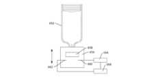
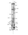
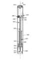
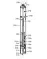
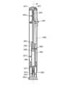
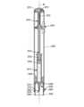
本開示に従った薬物送達システムは、(一次容器、例えば注射器、バイアル、またはカートリッジとも称され得る)貯蔵部を有する薬物送達装置を含んでもよい。貯蔵部は、薬または薬剤とも称され得る薬物を含んでもよい。薬物は、ペプチド、ペプチボディ、または抗体等の様々な生物製剤であり得るが、これらに限定されない。薬物は、流体または液体の形態でもよいが、本開示は、特定の状態に限定されない(例えば、例えば溶液、ゲル、または凍結乾燥製剤の間の区別を意図しない)。薬物送達装置はまた、貯蔵部に接続されるかまたは貯蔵部に流体連通で接続可能な第1の端と、患者内に挿入される第2の端と、を有する送達カニューレも含む。本明細書において使用する場合、用語「送達カニューレ」または「カニューレ」は、本明細書で、流体の送達のために身体内に挿入することができる管を意味すると定義される。カニューレは、例として、かつ制限としてではなく、剛性もしくは半剛性針または鈍端カニューレを含み得るか、または、可撓性の形態であり得る。カニューレは、薬物送達装置他の要素と一体化されてもよいか、またはカニューレは、使用の直前まで薬物送達の他の要素から分離されていてもよい。ある特定の実施形態によれば、薬物送達装置は、第2の端を患者内に導入するためのインサータをさらに含んでもよいが、これは、本開示の各々の実施形態によれば必要ではない。インサータは、装置内に引き戻されてもよいか、または引き戻されなくてもよく、これにより患者内にカニューレを残す。A drug delivery system according to the present disclosure may include a drug delivery device having a reservoir (which may also be referred to as a primary container, e.g., a syringe, a vial, or a cartridge). The reservoir may include a drug, which may also be referred to as a medicine or agent. The drug may be, but is not limited to, various biologics, such as peptides, peptibodies, or antibodies. The drug may be in the form of a fluid or liquid, although the present disclosure is not limited to a particular state (e.g., does not intend to distinguish between, e.g., solutions, gels, or lyophilized formulations). The drug delivery device also includes a delivery cannula having a first end connected to or connectable in fluid communication with the reservoir and a second end that is inserted into the patient. As used herein, the term "delivery cannula" or "cannula" is defined herein to mean a tube that can be inserted into the body for delivery of a fluid. The cannula may include, by way of example and not by way of limitation, a rigid or semi-rigid needle or a blunt cannula, or may be in a flexible form. The cannula may be integrated with other elements of the drug delivery device, or the cannula may be separate from other elements of the drug delivery device until immediately prior to use. According to certain embodiments, the drug delivery device may further include an inserter for introducing the second end into the patient, although this is not required according to each embodiment of the present disclosure. The inserter may or may not be retracted back into the device, thereby leaving the cannula in the patient.
薬物送達装置の前述の説明を考慮して、装置は、自動注入装置または身体上注入装置、もしくは注入器とみなしてもよい(注入装置への言及は、差異が示唆されている程度において注入器への言及もまた含むことが意図される)。自動注入装置は、使用者の皮膚への装置の単回の適用中に単回用量を投与する単回使用の装置でもよいが、自動注入装置は、単回使用の装置のみに限定されず、これらは複数回使用の装置でもよい。身体上注入装置は、使用者の皮膚への装置の1回以上の適用中、複数の投与量を投与する複数回使用の装置であり得るが、身体上装置は、単回使用の装置としても使用されてもよい。自動注入装置または身体上注入装置のいずれも、アセンブリが、例えば、貯蔵部を再充填することによってか、空の貯蔵部を取り除きそれを充填された貯蔵部と交換することによってか、またはカニューレを交換することによって使用及び再使用され得る、再使用可能であるアセンブリまたはサブアセンブリを有してもよい。In view of the foregoing description of the drug delivery device, the device may be considered an autoinjector or an on-body injection device, or an injector (reference to an injection device is intended to also include reference to an injector to the extent that a distinction is suggested). An autoinjector may be a single-use device that administers a single dose during a single application of the device to the user's skin, but autoinjectors are not limited to single-use devices only, as they may be multiple-use devices. An on-body injection device may be a multiple-use device that administers multiple doses during one or more applications of the device to the user's skin, but on-body devices may also be used as single-use devices. Either an autoinjector or an on-body injection device may have an assembly or subassembly that is reusable, in that the assembly may be used and reused, for example, by refilling the reservoir, by removing an empty reservoir and replacing it with a filled reservoir, or by replacing the cannula.
上で述べたように、本開示に従ったシステムまたは方法は、薬物送達装置に関連する1つ以上の状態を判定する。As discussed above, a system or method according to the present disclosure determines one or more conditions associated with a drug delivery device.
例えば、本システムまたは本方法は、薬物送達装置が1つ以上の動作状態(すなわち、薬物を患者に送達するための薬物送達装置の動作に関連する状態)にあるかどうかを判定してもよい。一般的な動作状態の網羅的でないリストには、(i)包装された/配布の準備が整った動作状態、(ii)包装された/配布された動作状態、(iii)解梱された/投与の準備が整った動作状態、(iv)滅菌バリアが除去された動作状態、(v)装置が適用された動作状態、(vi)カニューレが注入された(または挿入された)動作状態、(vii)薬物送達が開始された動作状態、(viii)薬物送達が完了した動作状態、及び(ix)装置が除去された動作状態が含まれ得る。本システムまたは本方法は、一般的な動作状態の各々で特定の動作状態を判定してもよく、例えば、本システムまたは本方法は、プランジャーが(薬物貯蔵部を画定する)穴の第1の端から穴の第2の端に動かされたかどうかを判定して、薬物送達装置が「薬物送達完了」状態にあるかどうかを判定してもよい。For example, the system or method may determine whether the drug delivery device is in one or more operational states (i.e., states associated with the operation of the drug delivery device to deliver a drug to a patient). A non-exhaustive list of common operational states may include: (i) a packaged/ready for distribution operational state; (ii) a packaged/distributed operational state; (iii) an unpackaged/ready for administration operational state; (iv) a sterile barrier removed operational state; (v) a device applied operational state; (vi) a cannula injected (or inserted) operational state; (vii) a drug delivery initiated operational state; (viii) a drug delivery completed operational state; and (ix) a device removed operational state. The system or method may determine a specific operational state at each of the common operational states; for example, the system or method may determine whether the plunger has been moved from a first end of the bore (defining the drug reservoir) to a second end of the bore to determine whether the drug delivery device is in a "drug delivery completed" state.
さらに、本システムまたは本方法は、薬物送達装置が1つ以上の条件状態(すなわち、薬物を患者に送達するための薬物送達装置の動作に必ずしも関係しない、薬物送達装置の条件に関連する状態)にあるかどうかを判定してもよい。条件状態の網羅的でないリストには、(i)(例えば、製造年月日または有効期限に対する)製品年齢、(ii)滅菌/汚染、(iii)温度(または温度履歴)、及び(iv)配向が含まれ得る。条件状態の判定は、動作状態の判定の一部として見なされてもよく、例えば、温度状態の判定は、「投与の準備が整った」状態の一部として見なされてもよい。あるいは、動作条件及び条件状態は、別個に決定されてもよい。Additionally, the system or method may determine whether the drug delivery device is in one or more condition states (i.e., states related to the condition of the drug delivery device that are not necessarily related to the operation of the drug delivery device to deliver the drug to the patient). A non-exhaustive list of condition states may include: (i) product age (e.g., relative to date of manufacture or expiration date), (ii) sterility/contamination, (iii) temperature (or temperature history), and (iv) orientation. The determination of a condition state may be considered as part of the determination of an operational state, e.g., the determination of a temperature state may be considered as part of a "ready for administration" state. Alternatively, the operational conditions and condition states may be determined separately.
これらの状態は、1つ以上のセンサの使用により判定されてもよい。センサは、判定される条件状態に特有のものであってもよく、例えば、貯蔵部に隣接して配設された熱電対は、薬物送達装置の温度状態を判定するために使用されてもよい。センサは、判定される動作状態に特有のものであってもよく、例えば、「滅菌バリアが除去された」動作状態を判定するために、スイッチは、針保護装置に結合されていつ針キャップが除去されたかを判定してもよく、スイッチは、針キャップがカニューレの第2の端上に配設されたときに開き、スイッチは、針保護装置がカニューレの第2の端上に配設されていないときに閉じる。センサを使用して条件状態及び動作状態の両方を判定してもよく、例えば、熱電対を使用して、装置の温度条件状態(またはより具体的には薬物)を判定してもよく、かつ/または熱電対を使用して、「投与の準備が整った」動作状態を判定してもよい。These states may be determined through the use of one or more sensors. The sensor may be specific to the condition state being determined, for example, a thermocouple disposed adjacent to the reservoir may be used to determine the temperature state of the drug delivery device. The sensor may be specific to the operational state being determined, for example, to determine the "sterility barrier removed" operational state, a switch may be coupled to the needle protection device to determine when the needle cap is removed, the switch opens when the needle cap is disposed on the second end of the cannula, and the switch closes when the needle protection device is not disposed on the second end of the cannula. Sensors may be used to determine both the condition state and the operational state, for example, a thermocouple may be used to determine the temperature condition state of the device (or more specifically the drug) and/or a thermocouple may be used to determine the "ready for administration" operational state.
システムまたは方法は、判定された状態を使用して、薬物送達装置の動作を制御してもよい。例えば、システムは、センサに結合された制御装置を含んでもよく、上述の薬物送達装置のアセンブリもしくはサブアセンブリのうちの1つ以上に、または薬物送達装置の1つ以上の追加のアセンブリもしくはサブアセンブリに結合されてもよい。制御装置は、判定された状態に従って、これらのアセンブリもしくはサブアセンブリを起動するか、または抑制するように構造的に適合されるか、または(電気的または電気機械的である場合)そのようにプログラムされてもよい。例えば、薬物送達装置は、注入装置の動作を制限するかまたは完全に抑制するロックアウトを含んでもよく、制御装置は、薬物送達装置(及び特に貯蔵部内の薬物)の温度状態が閾値状態未満である場合、可逆的様式でロックアウトを作動させてもよい。The system or method may use the determined condition to control operation of the drug delivery device. For example, the system may include a controller coupled to the sensor and may be coupled to one or more of the assemblies or subassemblies of the drug delivery device described above, or to one or more additional assemblies or subassemblies of the drug delivery device. The controller may be structurally adapted or (if electrical or electromechanical) programmed to activate or inhibit these assemblies or subassemblies according to the determined condition. For example, the drug delivery device may include a lockout that limits or completely inhibits operation of the infusion device, and the controller may activate the lockout in a reversible manner when the temperature condition of the drug delivery device (and particularly the drug in the reservoir) is below a threshold condition.
システムまたは方法は、判定された状態(複数可)を別の装置またはシステムに通信してもよく、この通信は、薬物送達装置の動作を制御するために判定された状態(複数可)の使用と併せて行われてもよい。例えばシステムまたは方法は、通信リンクを使用して判定された状態(複数可)をネットワーク化された装置と通信してもよい。この意味で、ネットワーク化された装置は、通信リンク上で少なくとも1つの他の装置と通信する任意の装置を含むことが意図され、例えばBluetooth(登録商標)接続を使用するモバイル機器(例えば、携帯電話もしくはモバイルコンピューティングデバイス)、またはWi-Fi接続を使用したコンピューティングデバイス等の装置との通信を含んでもよい。ネットワーク化された装置は、サーバ等のネットワーク化された装置を含むネットワークを介して、薬物送達システムから遠く離れた他のコンピューティングデバイスに、判定された状態を通信してもよい。本開示のある特定の実施形態によれば、システムは、ネットワークと直接通信する(すなわち、中間のネットワーク化された装置なしで。システムはネットワーク化された装置である)か、または(例えば、3Gアンテナを使用して)サーバ等の遠隔コンピューティングデバイスと直接通信する。ネットワークを介して通信された状態情報は、次いで、例えば、患者が遵守しているかどうか、または薬物送達装置のクラスがシステム異常を呈しているかどうかを判定するために、使用されてもよい。状態情報は、他の様式でも使用されてもよい。The system or method may communicate the determined state(s) to another device or system, and this communication may be done in conjunction with the use of the determined state(s) to control the operation of the drug delivery device. For example, the system or method may communicate the determined state(s) to a networked device using a communication link. In this sense, a networked device is intended to include any device that communicates with at least one other device over a communication link, and may include communication with devices such as mobile devices (e.g., mobile phones or mobile computing devices) using a Bluetooth connection, or computing devices using a Wi-Fi connection. The networked device may communicate the determined state to other computing devices remote from the drug delivery system through a network that includes networked devices such as a server. According to certain embodiments of the present disclosure, the system communicates directly with the network (i.e., without an intermediate networked device; the system is a networked device) or directly with a remote computing device such as a server (e.g., using a 3G antenna). The status information communicated over the network may then be used, for example, to determine whether a patient is compliant or whether a class of drug delivery device is exhibiting a system anomaly. The status information may also be used in other manners.
システム及び方法はまた、薬物、薬物送達装置、もしくは使用者の識別に関連した情報、及び/またはこの識別情報の通信に従った薬物送達装置の制御も含んでもよい。薬物に関連する識別情報には、薬物名、薬物濃度、投与量情報、ロット番号または通し番号、ならびに製造及び/または期限切れの日付が含まれ得る。薬物送達装置に関連する識別情報には、装置タイプ(例えば、自動注入装置、身体上注入装置)、ロット番号または通し番号、及び製造日が含まれ得る。使用者に関連する情報には、患者名、人口統計データ情報、及び患者サブグループ情報が含まれ得る。この情報は、上で論じられた状態情報とは対照的に「静的」情報と称され得る。The systems and methods may also include information related to the identity of the drug, the drug delivery device, or the user, and/or control of the drug delivery device pursuant to communication of this identity information. Identification information related to the drug may include drug name, drug concentration, dosage information, lot or serial number, and manufacture and/or expiration date. Identification information related to the drug delivery device may include device type (e.g., autoinjector, on-body injector), lot or serial number, and manufacture date. Information related to the user may include patient name, demographic information, and patient subgroup information. This information may be referred to as "static" information, as opposed to the status information discussed above.
情報の通信に関して、及び特に直前に論じられた識別情報に関連して、全ての情報が、利便性のため、患者のプライバシー、またはデータ機密保護の懸念のために、全ての異なる関係者にとって有用であるか、所望されるか、またはさらにはアクセス可能であるわけではないことが理解される。With regard to communication of information, and particularly with regard to the identifying information discussed immediately above, it is understood that not all information will be useful, desirable, or even accessible to all different parties, for reasons of convenience, patient privacy, or data security concerns.
図1は、本開示の実施形態に従った薬物送達システム100を図示している。薬物送達システム100は、治療計画の一部として薬物を注入するために薬物送達システム100を使用し得る患者102と関連付けられてもよい。薬物送達システム100は、1つ以上の中間コンピューティングデバイス及び/または1つ以上のネットワークを介して、コンピューティングデバイス(例えばサーバ)104と通信してもよい。次いで、サーバ104は、1つ以上の中間コンピューティングデバイス及び/または1つ以上のネットワークを介して、薬物送達システム100、患者102、及び1つ以上のコンピューティングデバイスと(これらの関連する関係者と共に)通信してもよい。図1にも示されるとおり、サーバ104は、例えば3Gアンテナを使用して薬物送達システム100と直接通信してもよい。1 illustrates a
例えば、薬物送達システム100は、第1の通信リンク112を介してモバイルコンピューティングデバイス110(例えば、スマートフォン)と、及び第2の通信リンク116を介してコンピューティングデバイス(例えば、パーソナルコンピュータまたは専用ハブ)114と通信していることが示されている。リンク112、116の両方は、例えば、Bluetooth等の近距離通信プロトコルに従って動作してもよい。モバイルコンピューティングデバイス110が、通信リンク120を介してセルラーネットワーク118と通信し得る一方で、他のコンピューティングデバイス114は、通信リンク124を介して実配線のネットワーク(例えば、ローカルエリアネットワークまたは広域ネットワーク)122と通信し得る。これらのネットワーク118、122もまた、サーバ104と通信してもよい。For example, the
ネットワーク118、122は、サーバ104と、患者102と関連した1人以上の関係者、例えば患者の介護人130、支援者132、及び医療提供者134との間の通信を、自身のモバイルコンピューティングデバイス(例えば、スマートフォン)を介して容易にすることができる。サーバ104は、患者102と関連した1人以上のさらなる関係者と関連した1つ以上のコンピューティングデバイス(例えば、サーバ)とも通信していてもよい。例えば、ネットワーク122を介してサーバ104と通信している健康管理システムサーバ140、決済サーバ142、薬局サーバ144、物流業者サーバ146、及び政府機関サーバ148が示されている。ネットワーク118、122は、互いに通信していてもよいことも理解されるであろう。The
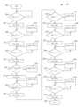
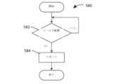
図2は、薬物送達システムの様々な状態を判定し、これらの状態に従って薬物送達システムを制御し、判定された状態情報をモバイル機器110及び/またはサーバ104等のコンピューティングデバイスに通信するための、図1の薬物送達システム100等の薬物送達システムを操作する方法200を図示している。図1の流れ図の大まかな再考察から、図2に従った方法200が、薬物送達システムの一部である薬物送達装置の様々な動作状態の判定と、これらの動作状態に関連してか、またはこれらに関して取られた行動及び行われた通信と、を図示していることが理解されるであろう。方法200が本明細書に記載される行動を含む一方で、本開示に従った薬物送達システムを操作する方法の他の実施形態は、例えば、図3に具体的に示されるとおり、本明細書に記載される動作のうちのいくつかのみを含んでもよいことも理解されたい。本開示に従った薬物送達装置を操作する方法の他の実施形態に含まれない図2に概説されるこれらの動作は、省略または除外されてもよい。2 illustrates a
薬物送達システムからの動作及び通信は、図2に示されるとおり、装置が製造から処分までの使用可能な製品ライフサイクルを経るに従い、薬物送達装置の動作状態と共に変化してもよい。実際、単一のセンサに基づいて下される判定は、薬物送達装置の動作状態に従って変化してもよい。例として、滅菌を維持するためのカニューレの第2の端上に配設された針キャップを利用するこれらの薬物送達装置に関して、針キャップセンサを使用して下された、針キャップが包装体または包装除去の前にカニューレの第2の端上またはそれの周囲から除去されたという判定が、一次容器の一体性が損なわれたことを示し得るのに対し、包装体または包装除去後のカニューレの第2の端上またはその周囲からの針キャップの分離または除去は、装置が薬物を投与する準備が整っていることを示し得る。The operations and communications from the drug delivery system may change with the operational state of the drug delivery device as the device goes through a usable product life cycle from manufacture to disposal, as shown in FIG. 2. Indeed, the determination made based on a single sensor may change according to the operational state of the drug delivery device. As an example, for those drug delivery devices that utilize a needle cap disposed on the second end of the cannula to maintain sterility, a determination made using the needle cap sensor that the needle cap has been removed from on or around the second end of the cannula prior to packaging or removal may indicate that the integrity of the primary container has been compromised, whereas separation or removal of the needle cap from on or around the second end of the cannula after packaging or removal may indicate that the device is ready to administer the drug.
方法200はブロック202から開始し、薬物送達システムが包装されたと判定されたとき、ブロック204からブロック206及び208に続く。具体的には、装置がブロック204で包装されたと判定されたら、通信がブロック206で行われて装置の動作状態変化を報告し、方法は、装置が配布されたかどうかの判定が下されるブロック208へと続く。The
薬物送達システムが包装されたという判定と、薬物送達システムが使用者に配布されたという判定との間で、薬物送達装置は、サプライチェーンの異なる部分を通過してもよい。薬物送達システムが通過し得るサプライチェーンの部分は、薬物送達装置内の薬物、患者もしくは医療専門家であり得る使用者による薬物送達装置に意図される用途、または他の要因(例えば、薬物送達装置自体の構造及び特性)に左右され得る。Between the determination that the drug delivery system is packaged and the determination that the drug delivery system is distributed to a user, the drug delivery device may pass through different portions of the supply chain. The portions of the supply chain that the drug delivery system may pass through may depend on the drug in the drug delivery device, the intended use of the drug delivery device by the user, who may be a patient or a medical professional, or other factors (e.g., the structure and characteristics of the drug delivery device itself).
包装された装置が製造から現れると、真贋性、環境履歴、及び配布全体を通して現在または過去の位置についての情報の最新の知識を維持する関心が存在する。したがって、方法及びシステムが次の動作状態への移行の判定をブロック208で待つ一方で、システムはこの情報をブロック210で監視及び通信してもよい。この状態で情報の収集及び報告を自動化することにより、サプライチェーンパートナーは、改善された情報及びサプライチェーン管理システムを活用することができる。製品識別、有効期限、及び偽造対策等の情報は、物流、倉庫保管、及び税関検査官にとって有用であり得る。この情報は、製造中に併用製品(すなわち、薬物、装置、及び/または生物学的製剤を組み合わせる治療薬ならびに診断薬)について知られているものに追加されるとき、製品輸送または返品及びリコールによる交換等の現場の事象の際、関心のあり権限を与えられた関係者に製品位置に関する注意を促すのに役立ち得る。As packaged devices emerge from manufacturing, there is an interest in maintaining up-to-date knowledge of information about authenticity, environmental history, and current or past location throughout distribution. Thus, while the method and system await a decision to transition to the next operational state in
製造業者と患者または医療提供者への薬物送達システム配布との間で薬物送達システムが取る経路に応じて、薬物送達システムはまた、システムがブロック210で情報を監視及び通信も行い得る薬局も通過してもよい。薬物送達システムが薬局を通過する場合、薬物/投与量/装置、環境履歴、有効期限、偽造対策、及び位置データ等の情報は、末端使用者に送達されたときに、有用な情報を在庫管理及び製品品質の確保の責任者に提供することができる。ラベル及び取扱説明書情報へのアクセスを始動させる信号の組み込みは、送達装置または薬物製品に関する末端使用者の訓練において価値を提供することができ、使用者コミュニティへのアクセスを提供することができ、かつ製品訓練または関連資料の有効性に関する情報の流れを使用者または使用者のネットワークに提供することができる。これらの信号は、製造中に併用製品について知られているものに追加されるとき、製品輸送または返品及びリコールによる交換等の現場の事象の際、製品位置に注意するのに役立ち得る。Depending on the path the drug delivery system takes between the manufacturer and distribution of the drug delivery system to the patient or healthcare provider, the drug delivery system may also pass through a pharmacy where the system may also monitor and communicate information in
包装された製品が使用者(例えば、患者または医療提供者)に配布されたという判定がブロック208で下されたら、方法200は、動作状態における変化が通信されるブロック212に続いてもよい。方法200は、ブロック214の薬物送達装置が解梱されたかに関する判定を続けてもよい。薬物送達装置が解梱されたという判定が下されない場合には、方法200は、ブロック216で薬物送達システムを監視し、情報を報告してもよい。薬物送達装置が解梱されたという判定が下された場合には、方法は、動作状態変化の通信をするブロック218に続いてもよい。If a determination is made at
この動作状態中、環境履歴、使用に関する指示、保管指示、製品真贋性などの情報、または生産された材料のロット、有効期限、薬リマインダー、及び配送の間中の現在位置もしくは予測される到着に対する任意の関連した現場の警告は、使用者の興味を引く情報を提供する。温度等の環境条件に関する信号を提供するためのセンサの使用は、製品が現在使用に適しているか、すなわち、(ブロック218で発生するレポートを伴い)方法がブロック214からブロック220に進んでもよいか、使用者の理解を助けることができる。これの1つの広範な例は、温度が15C等のある特定の閾値を超えたときの、送達及び報告のための高活動状態への電子装置の「覚醒」である。これは、冷蔵に装置に戻すための、または24時間以内に投与するための(例えば、使用者のネットワーク化された装置を介した)使用者へのメッセージをもたらし得る。同様に、感知された温度は、薬物製品が15C等の事前に設定された閾値未満に下がる場合、電子装置を低エネルギーの「スリープ」に戻し得る。During this operational state, information such as environmental history, usage instructions, storage instructions, product authenticity, or lot of material produced, expiration date, drug reminders, and any related on-site alerts for current location or expected arrival during delivery provide information of interest to the user. The use of sensors to provide signals regarding environmental conditions such as temperature can help the user understand if the product is currently suitable for use, i.e., the method may proceed from
ブロック214で装置が(恐らく使用者によって)解梱されたという判定が下された場合には、方法200は、ブロック218で動作状態変化を報告し、ブロック220の判定に進んでもよい。上で述べたように、方法200がブロック220に進み得る前に、方法は、ブロック214に示されるもの以外の判定を実施することが可能である。If a determination is made at
ブロック220でのシステムが使用の準備が整ったかどうかの判定において、提示された製品の質を検証することは一般的である。使用者がこの動作を行ってもよい一方で、システムは、この動作を実行するセンサも含んでもよい。例えば、検証には、真贋性を確認するためのラベル情報の検証、破損の徴候または針キャップが配送で外れていないかを確認するための装置の目視検査、色及び透明さに関する薬物製品容器の目視検査が含まれ得る。検証にはまた、装置の環境履歴が、装置を安全に使用することができるようなものであるかどうかの判定も含まれる。そのような判定は、薬物製品または送達装置を損なったかもしれない保管及び配布の間中の環境条件を考慮してもよい。装置内にセンサ(例えば、針キャップの位置もしくは近接センサまたは温度センサ)を含むことにより、これらの検査ステップのうちの多くを自動化することができ、使用者に格段の使用しやすさ、ならびに使用者及び使用者のネットワークにより多くの情報を提供することができる。In determining whether the system is ready for use at
ブロック220で下された判定によれば、方法200は、使用者が装置を使用する代わりに装置を廃棄するブロック222に進んでもよい。例えば、装置の環境履歴が、装置を安全に使用することができないようなものであると、ブロック220で判定される可能性がある。そのような場合、装置は、装置がブロック222で廃棄されると使用者に示してもよく、この情報をそのような装置の判定を追跡する遠隔サーバに通信してもよいか、またはこれを、ネットワーク化可能かもしくはネットワーク化されているローカル装置(モバイル、携帯電話または他のモバイル機器、あるいは持ち運びできるコンピューティングデバイス等)と通信し、かつ情報を遠隔サーバに通信してもよい。Depending on the determination made in
その一方で、システムが投与の準備が整ったという判定がブロック220で下された場合、方法200は、動作状態における変化の報告をしてブロック224に進んでもよい。次いで、方法200は、バリアがもはや滅菌状態になく、時期尚早に配置されたか、またはバリアが、装置の滅菌がもはや維持されていないかまたは維持されることをもはや保証できないような、薬物送達装置から時期尚早に除去されたかもしくは分離されたかの判定が下されるブロック226に続いてもよい。その際、バリアは、針キャップ等の滅菌バリア(すなわち、微生物の侵入を防ぎ、使用の時点で製品の滅菌の提示を可能にする最小包装)でもよい。バリアは依然として滅菌状態にあるという判定がブロック226で下された場合には、方法220は、システムの動作状態及び条件状態が監視され、情報がローカルまたは遠隔装置に通信されるブロック228にとどまってもよい。バリアがもはや滅菌状態にないという判定がなされた場合には、方法200は、動作の変化が報告されるブロック230に続いてもよく、方法200は、ブロック232に続いてもよい。On the other hand, if a determination is made at
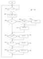
ブロック226で下される判定に関して、自動注入装置及び身体上装置が、針または注入ヘッドの滅菌を維持する、投与の直前に除去される構成要素または包装製品を有することは一般的である。時折、外側の保護包装は、薬剤投与の数日前に不適切に除去され廃棄される一方で、通常患者は、滅菌バリアが装置から除去されたとき、挿入及び/または注入まであと数分以下であり得る。この判定はまた、薬物送達装置電子装置が、重要な機能が実施される前に、製造、保管、及び配布の間中、適切な電力を確実にするために余分なコスト及びバルクを必要とすることなく、注入プロセス中に「覚醒している」ことを確実にする重要な機会も提供する。Regarding the determination made at
滅菌バリアを除去すると高活動状態にまで「覚醒」させるように電子装置を始動させることにより、スマート薬物送達装置の内蔵電子装置は、製造、保管、及び配布中に大幅に改善された電力消費をもたらすことができる。ある特定の実施形態によれば、例えば、起動、予備検査の完了、及び投与の試み前の患者/使用者との対話を含む起動順序は、10~200秒かかり得る(この対話には、装置/薬物が室温に温まるのを待つことが含まれるが、この動作を含めることは、必要な合計時間をさらに増加させ得る)。逆に、使用者は、内蔵電子装置を覚醒させるために身体接触または送達作動を待ってもよいが、これは恐らく全ての所望の「スマート」特徴の機会を提供しない。同様に、最初の包装の除去等の何かが電子装置を覚醒させるために使用された場合には、装置及び薬物送達システムの最適化を困難にし得るかなりの量の電力が送達の前に利用されるリスクが存在する。By triggering the electronics to "wake up" to a high activity state upon removal of the sterile barrier, the on-board electronics of a smart drug delivery device can provide significantly improved power consumption during manufacture, storage, and distribution. According to certain embodiments, for example, the start-up sequence, including start-up, completion of preliminary tests, and interaction with the patient/user before attempting administration, can take 10-200 seconds (this interaction can include waiting for the device/drug to warm up to room temperature, but including this action can further increase the total time required). Conversely, the user may wait for physical contact or delivery actuation to wake up the on-board electronics, but this would likely not provide an opportunity for all the desired "smart" features. Similarly, if something such as removal of the initial packaging were used to wake up the electronics, there is a risk that a significant amount of power would be utilized prior to delivery, which could make optimizing the device and drug delivery system difficult.
一般的に除去の容易さ、人間工学、または自明性を上昇させる機会を提供して来た、滅菌バリアと共に除去される構成要素を設計することが可能である。タブまたは他の電気絶縁特徴をこの構成要素へと設計することにより、この構成要素は、滅菌バリアの除去が電池または他の電源を接続し、電子装置を覚醒させて必要な機能を行うように、内蔵電子装置の電力回路内に挿入され得る。あるいは、バリアの除去は、スイッチの閉鎖をもたらし、電源を有する回路を完成し、したがって、システムの電源を入れ得る。It is possible to design a component that is removed along with the sterile barrier, which has typically offered the opportunity to increase ease of removal, ergonomics, or clarity. By designing a tab or other electrically insulating feature into this component, the component can be inserted into the power circuit of the on-board electronics such that removal of the sterile barrier connects a battery or other power source and wakes up the electronics to perform a required function. Alternatively, removal of the barrier may result in the closure of a switch, completing a circuit with the power source, thus powering up the system.
ブロック232で、薬物送達システムが患者に適用されたかどうかの判定が下される。自動注入装置に関しては、この判定は、自動注入装置が患者の皮膚に接して適所に保持されているかについての判定を伴ってもよい。身体上注入装置に関しては、この判定は、接着剤が身体上注入装置の表面上に露出し、注入装置が患者の皮膚の表面上に配設されたかについての判定を伴ってもよい。方法200のある特定の実施形態によれば、バリアがもはや滅菌状態ではなくなった後に、薬物送達システムが規定の時間以内に適用されなかったという判定がブロック232で下された場合、使用者は、ブロック234で装置を廃棄するように指示されてもよく、この事象はローカル及び/または遠隔装置に通信される。あるいは、ブロック232で装置が患者に提供されたというという判定が下された場合、動作状態変化がブロック236で報告され、方法200はブロック238に進む。At
いくつかの実施形態において、ブロック232で皮膚適用に関して下された判定は、方法200の残りを通して所定の間隔(例えば、5ミリ秒毎)で反復して行われてもよい。そのようにすることにより、患者への薬剤送達が完了する前に、薬物送達装置が、患者の皮膚から時期尚早に除去されたかどうかを判定することが可能であり得る。また、時期尚早の除去が起こった場合、薬剤送達の開始に対してそれがいつ起こったかを判定することが可能であり得る。時期尚早の除去のタイミングは、患者の皮膚からの薬物送達装置の除去前に、患者に実際に送達された薬剤の実際の量を算出するために使用されてもよい。In some embodiments, the determination made at
上記の事例でもそうであったが、いつ意図的接触が行われたかは、例えばどのような「スマート」機能が回路によって所望されるかに応じて、内蔵電子装置を低電力状態から「覚醒」させるための有用な機会であり得るため、これを知ることも有用であり得る。あるいは、装置が投与の準備が整ったことを確認するためのいくつかの検査は、使用者に注入の有用性におけるより強い確信を提供するために行われてもよい。As in the above case, it may also be useful to know when intentional contact has been made, as this may be a useful opportunity to "wake up" the on-board electronics from a low-power state, for example, depending on what "smart" functionality is desired by the circuitry. Alternatively, some testing to ensure the device is ready for administration may be performed to provide the user with greater confidence in the usefulness of the injection.
さらに、針保護装置を押し下げ製品を起動して患者の代わりに空気中に分配させることによって、多くの市販の注入装置が薬を分配させるようにだまされ得る、意図的に治療に従わないリスクが存在する。特にヒト組織及び適切な注入部位に予測される特性と合致する追加情報が存在する場合、装置が送達期間の間中ずっと身体と接触していたことを知り増分値が存在する。薬物送達の持続時間を伴う既知の身体接触と完了との重なりは、「針が挿入された」状態と類似の状態でさらに説明されるとおり、使用過失の事象において投与しそこねた投与量を推測するために使用することができる。Furthermore, there is a risk of intentional non-compliance as many commercially available injection devices can be tricked into dispensing medication by depressing the needle protection device and activating the product to dispense into the air instead of the patient. There is incremental value in knowing that the device was in contact with the body throughout the delivery period, especially when additional information exists that matches the expected characteristics of human tissue and the appropriate injection site. The overlap of known body contact and completion with the duration of drug delivery can be used to extrapolate the missed dose in the event of negligence, as further described in the analogy to the "needle inserted" condition.
方法200は、カニューレの第2の端が患者内に注入されたか、または挿入されたかをブロック238で判定する。多くの薬物送達装置で、患者の皮膚への薬物送達装置の適用と患者内へのカニューレの注入は同時ではない。例えば、薬物送達装置の様々なアセンブリまたはサブアセンブリが、薬物送達装置が適用されたことを認識し注入装置を起動するために必要な時間のために、適用と注入との間に遅延が存在し得る。あるいは、適用と注入との間の計画的遅延に起因するカニューレへの破損または患者の不快感を防ぐために、薬物の投与が、薬物送達装置の適用後時間遅延の経過した後に起こることが計画されているため、カニューレの注入に計画的遅延が存在し得る。さらに別の代替例で、身体上薬物送達装置において、誘導針と称される針が、起動して患者内に挿入されたままになり得るカニューレを挿入してもよい。次いで、針は送達装置内に再び後退し、カニューレを置き去りにする。薬剤の実際の注入または導入は、これの直後か、または後の所望の時間に起こることができる。そのため、方法200は、ブロック238でカニューレが挿入されなかったと判定された場合、ブロック240に進んでもよく、システムは、動作状態及び1つ以上の条件状態を監視し、その情報を通信してもよい。The
身体接触情報と同様、注入情報は、収集された情報におけるより高い確信を達成するために、他のプロセスと組み合わせて使用されてもよい。身体接触情報とは対照的に、標的の投与経路、例えば皮内、皮下、筋肉内、静脈内、眼内、または他の経路への針挿入を正確に測定することにより、薬物製品が正しい解剖学的深さ及び位置に送達されたという直接的な確認を提供することができる。Like body contact information, injection information may be used in combination with other processes to achieve greater confidence in the information collected. In contrast to body contact information, precise measurement of needle insertion into a target route of administration, e.g., intradermal, subcutaneous, intramuscular, intravenous, intraocular, or other route, can provide direct confirmation that the drug product has been delivered to the correct anatomical depth and location.
針挿入信号の1つの用途は、針が患者内に挿入された時点の送達ロックアウトの解除であり得る。あるいは、薬物送達の完了が起こり、かつ針が「送達始動」と「送達完了」との間の全期間に挿入されていた場合、非常に高い確信度の投薬成功が得られる。また反対に、事象のタイミングが適切に重ならない場合、システム送達特性に基づいて、成功裏に送達された投与量を予測することが可能であり得る。不完全なまたは不成功に終わった投与量投与が検出され報告されたとき、投与量相違も報告された場合、著しい増分値が存在する。「スマート薬物送達装置」は、異なる治療効果及び毒性リスクプロファイルを有する多くの異なる種類の薬剤のために使用することができる。例えば、一部の薬は、毒性のリスクは低いが、投与を逃したか、または不完全な投与量で合併症の高いリスクが存在する場合、任意の不完全な投与について第2の注入等によって、投薬の緊急の完了が必要であり得る。あるいは、医療提供者は、合併症のリスクが低い場合、逃したか、または不完全であった投与量を知りたいが、代替の予定を決める代わりに次の投与量を待つことを好み得る。重要なことは、逃した投与量が正しく記録され報告された場合、正確な逃した投与量を投与することにより、不完全な投薬に関連した問題を軽減する機会が存在し得、利益を最大化する一方で、ケアのコスト全体を最小化する機会を提供し得ることである。One use of the needle insertion signal could be the release of a delivery lockout at the time the needle is inserted into the patient. Alternatively, if completion of drug delivery occurs and the needle was inserted the entire period between "delivery initiated" and "delivery completed", then there is a very high degree of certainty of successful dosing. Conversely, if the timing of events does not overlap properly, it may be possible to predict the successfully delivered dose based on the system delivery characteristics. When an incomplete or unsuccessful dose delivery is detected and reported, there is significant incremental value if the dose discrepancy is also reported. A "smart drug delivery device" could be used for many different types of medications with different therapeutic effects and toxicity risk profiles. For example, some medications have a low risk of toxicity, but if there is a high risk of complications with a missed or incomplete dose, urgent completion of the dose, such as by a second injection, for any incomplete doses may be required. Alternatively, if the risk of complications is low, the healthcare provider may want to know the missed or incomplete dose, but would prefer to wait for the next dose instead of scheduling an alternative. Importantly, if missed doses are properly recorded and reported, there may be an opportunity to mitigate problems associated with incomplete dosing by administering the correct missed dose, providing an opportunity to minimize the overall cost of care while maximizing benefits.
ブロック238で針が挿入されたという判定が下された場合には、方法200は、ブロック242で動作状態変化を通信し、ブロック244で薬物の投与が開始されたか、または始動されたかを判定してもよい。カニューレが挿入されたが、投与をまだ開始していない場合、方法200は、ブロック246にとどまって薬物送達装置の状態を監視し、その情報を通信してもよい。カニューレの挿入と薬物製品の投与との間の遅延は、薬物送達装置のアセンブリまたはサブアセンブリの連続的動作のために起こり得る、すなわち、遅延は、カニューレが患者の皮膚への装置の適用と同時にまたはほぼ同時に患者内に挿入されたが投与はその後少なくとも時間遅延で起こるように計画され得る。If a determination is made at
送達の始動の成功は、概して、装置がカニューレを挿入し、次いで後に薬剤の注入を開始するようにプログラムされ得るときを除き、投薬の成功をもたらすと考えられる。始動したら、患者は一般的に治療結果をもたらすように意図された行動を行う。送達の始動は、特定の実施形態によれば、身体接触または針挿入単独と比較して、より高いレベルの専念の証拠として見なされ得る。一部の患者は、身体に装置を配置することにより、異なる部位を試して、送達を始動させる前に専念を「感じる」と考えられる。多くの装置は、そのような試みに対して送達を始動させないことを確実にするための機能を含む。したがって、送達の始動は、一般的に患者が処方された治療の投薬に精神的に専念したことを示すことが分かる。送達が始動したことを感知するための「スマート薬物送達装置」の機能の有効化は、遵守の表れとして多くの利害関係者に価値を提供する。他の方法との比較による成功した送達の測定の方向付けとしてではないが、始動信号の検出は、比較的単純な手段を通して達成することができ、より高い価値の価格及び信頼性を提供する。Successful initiation of delivery is generally considered to result in successful dosing, except when the device may be programmed to insert a cannula and then subsequently initiate infusion of the medication. Once initiated, the patient generally performs the action intended to result in a therapeutic outcome. Initiation of delivery, according to certain embodiments, may be viewed as evidence of a higher level of commitment compared to body contact or needle insertion alone. It is believed that some patients "feel" committed before initiating delivery by placing the device on the body, trying different sites. Many devices include features to ensure that delivery is not triggered in response to such attempts. Thus, it can be seen that initiation of delivery generally indicates that the patient has mentally committed to administering the prescribed therapy. Enabling the functionality of a "smart drug delivery device" to sense when delivery has been initiated provides value to many stakeholders as an indication of adherence. Although not as an orientation of measurement of successful delivery by comparison to other methods, detection of the initiation signal can be achieved through relatively simple means, providing a higher value price and reliability.
ブロック244で薬物製品の投与が開始されたという判定が下されたら、方法は、装置の動作状態変化がローカル及び/または遠隔装置と通信されるブロック248に進んでもよい。次いで、方法200はブロック250に進み、薬物製品の投与が完了したという判定が下される。薬物製品の投与が完了したという判定が下されるまで、システムは、ブロック252で装置の監視を継続し、情報を通信する。ブロック250で投与が完了したという判定が下されたら、動作状態における変化がブロック254で通信され、方法200はブロック256に進む。Once a determination is made at
投与または送達完了の捕捉は、特に他の装置状態情報と組み合わせて、有用な指標である。装置が他の装置状態を捕捉するための手段を有さない場合、それ自体に価値が存在し、実際に、他の状態を報告することができない場合、多くの利害関係者に十分な価値を提供する。しかしながら、他の装置状態と比較すると、投与送達完了の時間及び日付の捕捉は、薬物が成功裏に送達されたという非常に高いレベルの確信度(または反証)を提供することができる。例えば、投与量完了が、針が依然として挿入されているときに起こった場合、これは、患者または薬剤を投与している介護人が、装置が始動している間か、または始動した後に装置を身体から引き離さなかったことを裏付け、すなわち投与の精度を損なう。一般に入手可能な薬物送達装置は、身体に装置を適用する前の薬物送達を防ぐためにロックアウトしてもよいが、一度装置が身体に適用されると、送達の全時間中に装置を身体に固定したままにする手段が存在しない。ほとんどの場合、送達が始動された後に針が引き離された場合、薬物は送達を継続し、廃物として空気中にこぼれる。時折、薬剤は、特定の成分もしくは送達の速度に起因して痛みを伴い得るか、またはある特定の感覚を引き起こし得、したがって針の挿入後にでさえ、投与量を損なう反射運動を引き起こす。またあるときには、送達装置自体の動作が使用者を驚かせ、同じ反射運動を引き起こし得る。定められた治療に従うことを奨励するために必要な証拠、または治療方針を変更するために必要な証拠を患者に提供するために、使用者または使用者のネットワークが、緩徐な反応と治療に従わないこととの間の違いを理解することが大切であることが知られている。したがって、患者にとって薬物送達装置性能の包括的測定及び報告に驚くべき価値が存在する。Capture of dose or delivery completion is a useful indicator, especially in combination with other device status information. If the device does not have a means to capture other device status, it would have value in itself, and indeed would provide sufficient value to many stakeholders if it could not report other status. However, compared to other device status, capture of the time and date of dose delivery completion can provide a very high level of confidence (or disproof) that the drug was successfully delivered. For example, if dose completion occurred while the needle was still inserted, this would confirm that the patient or caregiver administering the drug did not remove the device from the body while or after the device was initiated, thus compromising the accuracy of the administration. Commonly available drug delivery devices may lock out to prevent drug delivery prior to application of the device to the body, but once the device is applied to the body, there is no means to keep the device secured to the body for the entire time of delivery. In most cases, if the needle is removed after delivery has been initiated, the drug will continue to be delivered and will spill into the air as waste. Sometimes, a drug may be painful or may cause certain sensations due to certain ingredients or the rate of delivery, thus triggering a reflex action that impairs the dose even after needle insertion. At other times, the action of the delivery device itself may startle the user and trigger the same reflex action. It is known that it is important for a user or a network of users to understand the difference between a slow response and non-compliance with a treatment, in order to provide the patient with the evidence needed to encourage compliance with a prescribed treatment or to change the course of treatment. Thus, there is a tremendous value for patients in comprehensive measurement and reporting of drug delivery device performance.
以下に開示される実施形態のうちのいくつかは、送達の全体的な進捗を監視するための範囲で拡張されてもよい。例えば、光学センサが、ストッパ材料を検出するように最適化され、完了情報を中継するために使用することができる送達行程の最後に配設された場合、同様に、薬物貯蔵部を通るプランジャーの移動と平行に設置された一連の光学センサは、移動の間中ずっと進捗を監視するために使用されてもよい。Some of the embodiments disclosed below may be extended in scope to monitor the overall progress of delivery. For example, if an optical sensor is optimized to detect stopper material and disposed at the end of the delivery stroke that can be used to relay completion information, similarly, a series of optical sensors placed parallel to the movement of the plunger through the drug reservoir may be used to monitor progress throughout the movement.
ブロック256で、方法200は装置が患者から除去されたかどうかを判定する。ブロック256での判定は、装置がもはや患者の皮膚と接触していないかどうかを判定する皮膚センサに基づいてもよい。他の実施形態によれば、判定は、皮膚からの除去後、薬物送達装置のカニューレの第2の端との接触を防ぐために配置される針シールドまたは他の構造について下されてもよい。さらに他の実施形態によれば、薬物送達装置の除去は、薬物送達装置の配向における変化に基づいてもよい。いずれにしても、薬物送達装置が除去されたと判定されるまで、方法及びシステムは、ブロック258で装置を監視し、ローカル及び/または遠隔装置と情報を通信してもよい。薬物送達装置が除去されたと判定されたとき、方法は、ブロック260でこの動作状態変化を通信し、ブロック262で終了する。At
装置の処分、及び代替的には収集センターによる使用済み装置の受取は、任意の保存されている情報を問い合わせる、及び/または以前の状態変化の証拠として機能するように受取自体を利用する最後の機会を提供する。以前に収集された任意のデータは、収集点でのダウンロードのために保存されてもよい。さらに、返品が、交換または現場での他の行為の賠償が保証されている状況に関しては、流通及び返品配送を通した薬物送達装置の位置の認識は、有益である。同じ信号は、返品の遠隔承認と組み合わせて、使用者への最小の影響で、返品配送が電子的に承認され、使用者または流通ネットワーク内の適切なパートナーによる支払いを可能にすることができる。The disposal of the device, and alternatively the receipt of the used device by a collection center, provides a final opportunity to query any stored information and/or utilize the receipt itself to serve as evidence of a previous state change. Any previously collected data may be stored for download at the collection point. Additionally, for situations where a return warrants replacement or other action on-site, awareness of the location of the drug delivery device throughout distribution and return delivery is beneficial. The same signal, combined with remote approval of the return, can allow the return delivery to be electronically approved and paid for by the user or an appropriate partner in the distribution network, with minimal impact to the user.
本開示の他の実施形態によれば、図2に関して記載されている様々な動作状態は、任意であると見なされ得ることが理解されるであろう。例えば、ブロック238及び244でカニューレの挿入及び薬物製品の投与開始に関連する判定を下すことは、例えば、装置が適用され、薬物製品投与が完了しているという判定がブロック232及び250で下された場合、必要でないかもしれない。さらに、方法200が、各々の動作状態変化後に動作状態変化の通信を含む一方で、動作状態変化のいずれもシステム内に保存されなくてもよいが、動作状態変化の各々の通信は、ブロック260まで起こり得ない。さらに、薬物送達装置の監視が、方法200がある特定の判定が下されるのを待っている間に起こると示されている一方で(例えば、ブロック208及び210)、この監視は、示される全ての事例で行われる必要はない。2 may be considered optional. For example, making a decision related to inserting a cannula and initiating administration of a drug product at
さらに、図2に記載される監視は、単に論じられている様々な動作状態変化の監視にとどまらないものを含み得ることが理解されるであろう。監視は、条件状態変化の監視も含んでもよい。事実、方法及びシステムは、1つ以上のセンサからの情報または信号が方法200に沿った様々な点で下される判定に使用され得る、これらの動作及び/または条件状態変化を行うための1つ以上のセンサを監視してもよい。Further, it will be appreciated that the monitoring described in FIG. 2 may include more than simply monitoring the various operational state changes discussed. Monitoring may also include monitoring condition state changes. In fact, the methods and systems may monitor one or more sensors for these operational and/or condition state changes, where information or signals from one or more sensors may be used in decisions made at various points along the
図3A~3Cは、本開示に従った方法及びシステムで起こり得る混合の動作及び条件状態監視のうちのいくつかを示していると見なされ得る方法300を図示している。方法300は、1つ以上のセンサがどのようにして上述の状態変化を判定するのに使用され得るかを示していると見なされ得る。さらに、方法300は、動作及び条件状態監視の開示ならびに図2に示されていないその情報の通信を提供していると見なされ得る。FIGS. 3A-3C illustrate a
まず図3Aを参照すると、方法300は、包装内の薬物送達装置から開始してもよく、方法は包装が開けられたことが判定されるまでブロック302で待機する。この時点で、装置は、システムが1つ以上の検証、照合、または検査を行い、確実に装置が投与の準備ができ、滅菌バリアが除去され、かつ/または装置が(正しく)適用された(図2の方法220のブロック220、226、232を参照のこと)ときまで、任意選択的にロックされてもよい。1つ以上の検証、照合、または検査の各々を行う前に、方法300は、検証、照合、または検査を実施するように薬物送達装置が適合されたか、またはプログラムされたかを判定してもよい。例えば、薬物送達装置の滅菌を検査するように薬物送達装置が適合されたか、またはプログラムされたかの判定は、ブロック304で下されてもよく、特に、検証または確認は、カニューレの第2の端に配設された滅菌バリアに関連してもよい。薬物送達装置が、滅菌検査を行うように適合されたか、またはプログラムされた場合、方法300は、滅菌バリアが例えばカニューレの第2の端上またはその周囲に配設されたか判定されるブロック306に進んでもよい。3A, the
ブロック306でバリアが定位置にあると判定された場合には、方法は、使用者がバリアを除去するように指示されるブロック308に進んでもよい。次いで、方法300は、バリアが除去されたかどうかをブロック310で決定してもよい。バリアが除去されたと決定されたとき、滅菌タイマーが開始し、滅菌タイマーの期限切れは、薬物送達装置がロック状態にされるか、またはその状態のままになることをもたらし、薬物送達装置の使用を防いでもよい。If the barrier is determined to be in place at
ブロック306で、バリアが定位置にない(すなわち、バリアが時期尚早に除去された)と決定された場合、方法300は、送達装置がロックされる(例えば、ロックまたはロックアウト装置が作動している)か、または装置が既にロックされていた場合には、送達装置がロック状態のままになる、ブロック312に進んでもよい。ある特定の実施形態によれば、ブロック312の送達装置のロックは、不可逆的でもよい。図3A~3Cに示される実施形態を含む他の実施形態によれば、ロックは、ブロック314で薬物製品(例えば薬物製品貯蔵部)が交換されたと判定されたら、戻されてもよい。薬物製品が交換されない場合か、または薬物製品を交換することができない(すなわち、ロックが不可逆的である)実施形態では、不合格の滅菌検査に関する情報は、システムによって通信されてもよい。If it is determined in
(i)ブロック304で、システムが装置の滅菌を検証、確認、または検査するように適合するという判定が下されたか、(ii)ブロック306で、バリアが定位置にあり、ブロック310で、続いてバリアが除去されたという判定が下されたか、または(iii)ブロック306で、バリアが定位置にないという決定が下されたが、ブロック314で、薬物製品が交換されたという判定が下された場合、方法300は、ブロック316に続く。ブロック316で、薬物送達装置が、目視及び/または環境検査を行い得るかどうかの判定が下される。装置がそのように適合された場合、方法は、目視検査及び/または環境条件が所望の閾値内にあるかどうかの判定を下す、ブロック318に進む。目視検査及び/または環境条件が所望の閾値外であるという判定が下された場合には、方法はブロック312、314に進んでもよい。目視検査及び/または環境条件が、所望の閾値内にあるという判定が下された場合には、方法300はブロック320に進んでもよい。If (i) a determination is made at
ブロック320で、薬物送達システムが、使用者識別を確認することができるかどうかの判定が下される。薬物送達システムがそのように適合されている場合には、方法300は、ブロック322に続き、使用者識別が薬物送達装置の使用のための権限と適合するかどうかの判定が下される。使用者が、権限を与えられた使用者としてブロック322で識別されない場合には、方法300は、薬物送達装置がロックされるか、またはロックされたままになるブロック324と、未遂の不正な使用に関する情報がローカル及び/または遠隔装置に通信されるブロック326と、に続く。使用者が権限を与えられた使用者として識別された場合には、方法300は、図3B及びブロック328に進む。At
ブロック328で、薬物送達システムが薬物製品の温度を確認するよう有効化されているかどうかに関するさらなる判定が下される。システムがそのように適合されている場合には、方法300はブロック330に続く。ブロック330で、薬物製品温度が、予測可能な送達の範囲内にある(高すぎまたは低すぎのいずれでもない)かどうかの判定が下される。ブロック330で温度が予測可能な送達の範囲内にないという判定が下された場合には、方法300は、装置が薬物製品を加熱または冷却して、製品の温度を範囲内に持っていき得るかどうかの判定が下されるブロック332に続く。システムがそのように適合されていない場合には、方法は装置がロックされるかまたはロックされたままになり、受動的加熱または冷却が起こることを可能にし得、かつ使用者が通知され得るブロック334に進む。任意選択的に、システムはまた、情報ローカル及び/または遠隔装置に通信してもよい。システムが、加熱または冷却を可能にするように有効化された場合には、方法は装置がロックされるかまたはロックされたままになり得、加熱または冷却が開始され得、使用者が通知され得るブロック336に進む。受動的または能動的加熱もしくは冷却(ブロック334、336)かに関わらず、方法300は、方法がブロック330に戻る前に、加熱または冷却が起こるための時間を提供するために、送達が遅延されるブロック338に続いてもよい。ある特定の実施形態によれば、方法300は、(例えば過度温度の場合)ブロック330の後に終了してもよく、その情報をローカル及び/または遠隔装置に通信してもよい。At
いくつかの実施形態において、ブロック330で行われる温度検査は、過去(例えば、保管、配布、配送中等)に薬物製品が経験した温度の範囲及び持続時間を判定するために、薬物製品の温度履歴の評価を伴ってもよい。薬物製品の温度履歴が、例えば、薬物製品が配送中に数日間または数時間、高温にさらされたことに起因して許容できない場合、制御装置350は、薬物製品を患者に送達するために使用することができないように薬物送達装置302をロックアウトしてもよく、さらに、薬物製品の温度履歴の非許容性を表すレポートをローカルコンピューティングデバイス304またはリモートコンピューティングデバイス306に送信するように、通信モジュール352を制御してもよい。いくつかの実施形態において、薬物製品の温度が閾値温度を超えたと判定されたら、制御装置は、温度が閾値温度未満に戻るまで実行するタイマーを開始してもよい。タイマーの持続時間が所定の制限時間を超えた場合、制御装置350は、薬物送達装置302をロックアウトし、薬物製品の温度履歴の非許容性を表すレポートを送信するように通信モジュール352を制御してもよい。In some embodiments, the temperature check performed in
図3Bに戻ると、ブロック328で装置が温度検査を行うように適合されていないか、またはブロック330で薬物製品の温度が所望の範囲内にあるという判定が下された場合には、方法は、装置が患者上に適切に位置付けられているか、または患者に対して適切に配向されているかを判定するために装置が有効化されたかどうかの判定が下されるブロック340に続いてもよい。装置がそのように適合された場合には、方法はブロック342に進み、装置が適切に配設または配向されたかどうかの判定が下される。その際、好適な挿入部位に応じて、装置の配向の知識は、好結果の注入の提供において、有用であり得る。例えば、腹部への自己投与は、恐らくおおよそ水平の自動注入装置軸の配向をもたらす。Returning to FIG. 3B, if a determination is made at
装置が適切に配設されていない場合には、方法はブロック344に進み、装置がロックされ得、使用者は装置を再配置または再配向するように指示される。次いで、方法300は、方法300が装置の位置に関するさらなる判定のためにブロック342に戻る前に、使用者が装置を再配置するための時間遅延が提供されるブロック346に進んでもよい。あるいは、装置が適切に配設されている場合には、方法はブロック348に進んでもよく、作動され得た任意のロックまたはロックアウトが取り除かれる(または装置のロックが解除される)。If the device is not properly positioned, the method proceeds to block 344, where the device may be locked and the user is instructed to reposition or reorient the device.
方法300は、送達が始動されたかどうかを判定するためにシステムが有効化されたかどうかの判定が下されるブロック350にとどまる。システムがそのように適合されたという判定が下された場合には、方法はブロック352に進み、装置が起動したか、または始動されたかの判定が下される。ブロック352で装置が始動されなかったという判定が下された場合には、方法300はブロック354に進んでもよく、システムは、使用者に装置を始動させるように指示してもよい。他の実施形態によれば、薬物送達装置は、時間遅延が完了したら自動的に装置を始動させる前に所定の及び/または事前にプログラムされた時間遅延が起こるのを待ってもよい。さらに他の実施形態によれば、方法300は、例えば汚染及び感染のリスクを低減させるためにブロック355でタイマーが経過したかどうか任意選択的に判定してもよい。そのような実施形態に従って、タイマーは、ブロック310でバリアが適切に除去されたという判定に基づいて開始されてもよく(またはさらなる実施形態に従ってバリアが除去されたという判定に基づいて開始されてもよく)、方法300がその事象からある特定の時間内に装置が始動されたと判定しない場合、方法300は、例えば図3B及び3Aに示されるようにブロック312に戻ってもよい。ブロック350で始動が起こったと判定された場合には、方法は使用者に装置の始動を通知してもよい、ならびに/または送達の日付、時間、及び位置が保存されるか、もしくは記録されてもよいブロック356に進む。任意選択的に、この情報もまた、システムと通信しているローカル及び/または遠隔装置に通信されてもよい。次いで、方法300は図3Cに続く。
システムが、装置が身体上に適切に位置付けられたままになっているか、または身体に対して適切に配向されたままになっているかを判定するように有効化されているかどうかのさらなる判定が、ブロック358で下されてもよい。システムがそのように適合されている場合には、方法300はブロック360に続き、装置が身体上に適切に位置付けられているか、または身体に対して適切に配向されているかどうかの判定が下される。装置が適切に位置付けられていないか、または配向されていない場合には、方法300は、患者の身体上の装置の位置または配向が判定されるブロック360に戻る前に、使用者が装置を再配置または再配向するように通知されるブロック362と、時間遅延が装置を再配置または再配向するために使用者に提供されるブロック364と、に続いてもよい。装置が適切に位置付けられているかまたは配向されている場合、方法300は、ブロック366に進んでもよい。任意選択的に、方法300は、装置が薬物製品を投与している時間中、装置が正しく位置付けられたままになっているかを確実にするために、定期的にブロック360を反復してもよい。A further determination may be made at
ブロック366で、システムが、投与が完了したかどうかを判定するように有効化されているかどうかの判定が下される。システムがそのように適合されている場合には、方法300はブロック368に続き、送達が完了したかどうかの判定が下される。ブロック368で送達が完了していないという判定が下された場合には、送達を完了することができるかどうかさらなる判定がブロック370で下される。送達が完了していないが完了され得る場合には、方法300は、装置が薬物製品の投与を継続することを許容されるブロック372を介してブロック368に戻る。送達が完了しておらず、かつ完了することができない(例えば、装置が患者の皮膚から除去されている)場合には、方法300はブロック374に続き、薬物及び薬物送達に関する情報が、ローカル及び/または遠隔装置に通信されてもよい。例えば、ある特定の動作状態(カニューレが挿入された、送達を開始した、送達が部分的に完了した)が起こったかどうか、動作状態のタイミング、及び投与された薬物製品の量に関する情報が通信されてもよい。At
ブロック368で送達が完了したという判定が下された場合には、方法はシステムが使用者に送達が完了したことを示すブロック376に進む。さらに、方法300は、ブロック378で薬物送達、薬物送達装置、及び薬物製品に関する情報をローカル及び/または遠隔装置に通信する。例えば、情報には、ある特定の動作状態が起こったこと及び動作状態のタイミングが含まれ得る。方法300はまた、システムが、装置が終始正しく位置付けられていたことの判定を下すように有効化されている場合、これも検証してもよい。方法300はまた、システムが、薬物製品の投与が完了したかどうかを判定するように有効化されておらず、薬物送達装置が、送達が完了したという結論に必然的に導く先行する動作状態のうちの1つ以上を通過したと判定されたという仮定を立てられた場合、ブロック378に進んでもよい。If a determination is made at
重ねて、上記の説明が、装置の一連の状態及びこれらの状態に依存し得る代替の動作を含む方法に関連する一方で、装置は図3A~3Cに示される各々及び全ての状態を判定するかまたは各々及び全ての動作を行う必要はないことに留意されたい。むしろ、当業者は、説明された状態のサブセットに基づいて装置を制御し得るか、またはそれを通信し得るシステムをもたらすように、ある特定の状態の判定またはある特定の動作の実行を省略もしくは除外してもよいことが理解されるであろう。Again, it should be noted that while the above description relates to a method including a series of states of the device and alternative actions that may depend on those states, the device need not determine each and every state or perform each and every action shown in FIGS. 3A-3C. Rather, one skilled in the art will understand that one may omit or exclude the determination of certain states or the performance of certain actions to result in a system that may control or communicate with the device based on a subset of the described states.
図2及び3A~3Cの示されている方法の文脈において薬物送達システムを操作する考えられる方法を論じて、薬物送達システムと通信している1つ以上のコンピューティングデバイスを操作する可能性のある方法が、これより図4に示される方法400の文脈において論じられる。方法400は、図1に示されるサーバ104等の単一のコンピューティングデバイスによって実行されてもよいことが理解されるであろう。あるいは、図4に関して論じられた動作は、例えばサーバ104と組み合わせたモバイル機器110またはコンピューティングデバイス114など、複数のコンピューティングデバイスによって実行されてもよい。Having discussed possible methods of operating a drug delivery system in the context of the methods shown in Figures 2 and 3A-3C, a possible method of operating one or more computing devices in communication with the drug delivery system will now be discussed in the context of
方法400は、ブロック402でレポートが薬物送達システムから受信されたかどうかに関する判定を用いて開始する。レポートが受信されていない場合、方法400はブロック402で待機し、ブロック402でレポートが受信されたと判定されたら、方法400はブロック404に進む。
ブロック404で、薬物送達システムから受信されたレポートは、1つ以上の記録を更新するために使用される。その際、方法400を実行するように適合またはプログラムされた1つ以上のコンピューティングデバイスは、1つ以上のメモリ記憶装置内の記憶装置から1つ以上の記録を取得し、薬物送達装置から受信した情報を1つ以上の記録に書き込み、次いで1つ以上の記録を1つ以上のメモリ記憶装置内に記憶する動作を行ってもよい。1つ以上のメモリ記憶装置は、1つ以上のコンピューティングデバイスの一部でもよいか、1つ以上のコンピューティングデバイスから分離していてもよいか、または1つ以上のコンピューティングデバイスの一部であるメモリ記憶装置及び1つ以上のコンピューティングデバイスから分離されている1つ以上のメモリ記憶装置のうちの1つ以上を含んでもよい(すなわち、記録はコンピューティングデバイスにおいて、バックアップ記憶装置内に、コンピューティングデバイスから分離され可能であれば遠隔に保存される)。At
上で言及されたとおり、レポートは、1つ以上の記録を更新するために使用されてもよい。例えば、患者記録データベース内に保存された個々の患者につき1つの記録が存在してもよい。患者記録は、例えば、個々の患者(例えば、患者102)がその患者の計画(複数可)を遵守しているかを追跡するために使用されてもよい。薬物送達システムデータベースに保存された、個々の患者によって使用される薬物送達システムに関する記録も存在してもよい。薬物送達システム記録は、薬物送達システムの使用期間を通した薬物送達システムに関する情報を保存するために使用されてもよい。薬物送達システム記録は、品質管理の目的のため(例えば、薬物送達システムに起因する障害または不具合に関して薬物送達システムの個々の事例を監視するためか、または薬物送達システムの設計、包装、発送、または取り扱いにおける改善を判定する上で補助し得るパターンに関して1つ以上の薬物送達システムの環境条件履歴を追跡するため)に、薬物送達システム製造業者または薬物供給業者によってアクセスされてもよい。薬物データベースに保存される薬物送達システムで使用される薬物に関する記録も存在してもよい。この記録は、薬物送達システム記録と類似した様式で品質管理の目的のために使用されてもよい。As mentioned above, the reports may be used to update one or more records. For example, there may be one record for each patient stored in a patient record database. The patient record may be used, for example, to track compliance of an individual patient (e.g., patient 102) with the patient's plan(s). There may also be records regarding the drug delivery systems used by individual patients stored in a drug delivery system database. The drug delivery system records may be used to store information about the drug delivery systems throughout their lifespan. The drug delivery system records may be accessed by drug delivery system manufacturers or drug suppliers for quality control purposes (e.g., to monitor individual instances of drug delivery systems for failures or malfunctions caused by the drug delivery system, or to track the environmental condition history of one or more drug delivery systems for patterns that may assist in determining improvements in the design, packaging, shipping, or handling of the drug delivery system). There may also be records regarding the drugs used in the drug delivery systems stored in a drug database. This record may be used for quality control purposes in a similar manner to the drug delivery system records.
ブロック404で記録の更新に加えて、方法400を実行するように適合またはプログラムされたコンピューティングデバイスは、薬物送達システムから受信したレポート内の情報に基づいて1つ以上の動作を実行するように適合またはプログラムされてもよい。例えば、コンピューティングデバイスは、ブロック406で動作を実行するように適合またはプログラムされてもよい。この動作は、レポート内で受信した情報及び/またはブロック404で更新された記録内に事前に保存された情報を必要とし得るだけでなく、他の患者記録、薬物システム送達記録、及び/または薬物記録から等の追加情報も必要とし得る。この場合には、これらの他の記録がアクセスされる必要があるという判定がブロック408で、及び(例えば、患者、薬物送達システム、及び薬物データベースからこれらの他の記録を取得し、取得されたらこれらの記録から情報を読み出すことによって)情報が取得されたという判定がブロック410で下されてもよい。次いで動作は、ブロック412で実行されてもよい。In addition to updating the record at
1つの例として、方法400を実行するように適合またはプログラムされた1つ以上のコンピューティングデバイスは、レポート内で受信された情報を使用して患者の遵守履歴を作成するように適合またはプログラムされてもよく、この遵守履歴は、患者がどれくらいうまく治療計画に従って来たかを判定するために、個々の患者によるその患者の治療計画に関する薬物送達システムの事例の使用を追跡し、この遵守履歴は患者記録内に保存されてもよい。さらに、1つ以上のコンピューティングデバイスは、薬局に個々の患者のための追加の薬物送達装置の発送を注文するために連絡を取るべきかどうか判定してもよく、追加の薬物送達システムの発送を注文するために、薬局に送信される通信を生成してもよい。さらに、1つ以上のコンピューティングデバイスは、例えば、個々の患者の治療計画の遵守を改善または支援するために、モバイル機器110を介してリマインダーを患者に送信すべきかどうかを判定してもよく、この場合、1つ以上のコンピューティングデバイスが、患者または装置の使用者に送信される通信を生成してもよい。さらに、1つ以上のコンピューティングデバイスは、薬物送達装置の動作が、例えば薬物送達装置から受信された条件状態のために修正されるべきであることを判定してもよい。例えば、1つ以上のコンピューティングデバイスは、薬物送達システムが、例えば、薬物送達システム内の薬物の温度履歴が原因でその使用を防ぐためにロックされるべきであることを判定してもよい。この場合、1つ以上のコンピューティングデバイスは、例えば、薬物送達システムの一部である薬物送達装置をロックするために薬物送達システムに送信される信号の形態の通信を生成してもよい。他の考えられる動作が以下に詳細に考察されるが、この考察は例示の目的のみのためであり、制限することを意図しない。As one example, one or more computing devices adapted or programmed to execute
ブロック412で行われた動作に応じて、または例えブロック406で動作を行う必要がないと判定されたとしても、方法400はコンピューティングデバイスが他の関係者と連絡を取るべきかどうか(ブロック414)、患者(もしくは患者と同じでない場合は使用者)と対話するべきかどうか(ブロック416)、または薬物送達システムの一部である薬物送達装置を制御するべきかどうか(ブロック418)の判定が下されるブロック414、416、418に進んでもよい。例えば、上で論じられたように、ブロック412で行われる動作は、薬局等の第三者、患者、または薬物送達装置に送信される通信または信号の生成を伴ってもよい。そのような場合、1つ以上のコンピューティングデバイスは、ブロック414、416、418で下された判定によって要求されるブロック420、422、424の動作を実行してもよい。あるいは、1つ以上のコンピューティングデバイスは、例えブロック406で動作を行う必要がないと判定されたとしても、ブロック420、422、424の動作を実行してもよい。例えば、1つ以上のコンピューティングデバイスは、受信された情報に関して動作を行うべきであると別々に判定する必要はないように(すなわち、1つ以上のコンピューティングデバイスがそのような情報のための中継局の機能を果たして,情報が受信されたという事実に基づいて通信が自動的に送信される)、薬物送達装置からのレポート内の情報の受信だけに基づいてある特定の情報を第三者420に転送してもよい。薬物送達装置からの情報の受信はまた、そのような行動を取る必要があるという別個の判定なしに患者/使用者に送信される通信を促してもよいか、または薬物送達システムに送信される信号を制御してもよく、通信または制御信号は、ある特定の情報及び/またはレポートが薬物送達システムから受信されたために、単純に送信される。Depending on the actions taken at
ブロック414、416、418で判定が下され、ブロック420、422、424の動作が実行されると、方法400は、ブロック402に戻って次のレポートを待ってもよい。1つ以上のコンピューティングデバイスは、薬物送達システムの異なる事例から受信されたレポートの各々に対して並行して方法400の動作を行ってもよいか、またはこのステップを各々のレポートについて順に行ってもよいことが理解されるであろう。並行して行われる場合、1つ以上のコンピューティングデバイスが、1つのレポートに関して動作を行うかどうかを判定してもよい一方で、1つ以上のコンピューティングデバイスは、その患者から受信したレポートに含まれる情報に関して別の患者と対話をしていてもよい。さらに、方法400を実行している1つ以上のコンピューティングデバイスは、1つ以上のコンピューティングデバイスの全ての実施形態に従って、上述の動作の各々を実行するように適合またはプログラムされる必要はない。例えば、1つ以上のコンピューティングデバイスのうちのあるデバイスが、各々の患者の記録を更新し、患者との対話が必要かどうかを判定するように適合またはプログラムされてもよい一方で、1つ以上のコンピューティングデバイスうちの別のものは、各々の薬物送達装置の記録を更新し、制御信号が薬物送達装置に送信されるべきことを判定するように適合またはプログラムされてもよい一方で、1つ以上のコンピューティングデバイスのうちの別のものは、いずれの記録も更新しないが、例えば、患者記録にアクセスして、アクセスされた患者記録と関連する患者のための薬物送達システムの追加事例を注文するために、薬局に連絡を取る必要があるかどうかを判定し、システムの追加の事例の注文が必要である場合、通信を生成するように適合されるか、またはプログラムされる。Once the determinations have been made at
上記の方法200、300、及び400が、薬物送達装置を制御及び/または監視するために使用され得、かつ薬物送達システムと1つ以上のコンピューティングデバイスとの間で通信され得る可能な状態及び識別情報、ならびに情報が薬物送達システム及び1つ以上のコンピューティングデバイスによってどのように使用されるかの断片のみに触れていることが理解されよう。追加の実施形態が、本開示に従って可能である。It will be appreciated that the
例えば、状態及び識別情報の非限定的なマトリックスには、以下が含まれ得る:For example, a non-limiting matrix of status and identity information may include:
条件状態情報:
温度
衝撃または振動暴露
光暴露
(その薬物と関連した)色及び/または濁度
配向
地理的位置
時間的情報 Condition Status Information:
Temperature Shock or vibration exposure Light exposure Color and/or turbidity (associated with the drug) Orientation Geographic location Temporal information
動作状態情報:
装置が包装から取り出された
装置が冷蔵(例えば、冷蔵庫)から取り出された
装置/薬物温度は、投与の準備が整った
送達を始動させた
装置が患者に適用された
装置が患者上の正しい位置/配向で適用された
カニューレが患者に挿入された、及び/または正しい組織に挿入された
送達が進行中である
送達が完了した
エラーが起こった Operating status information:
The device has been removed from packaging The device has been removed from refrigeration (e.g., refrigerator) The device/drug temperature is ready for administration Delivery has been initiated The device has been applied to the patient The device has been applied in the correct position/orientation on the patient The cannula has been inserted into the patient and/or into the correct tissue Delivery is in progress Delivery has been completed An error has occurred
装置識別情報:
薬物名もしくは識別、濃度、及び/または量
機密保護及び/または偽造防止情報
患者の処方/治療計画 Device identification information:
Drug name or identification, concentration, and/or amount; Confidentiality and/or anti-counterfeiting information; Patient prescription/treatment plan;
患者識別情報:
患者の診療現場診断
進捗の自己分析測定
指紋、暗証番号、または他の安全な識別情報 Patient Identification Information:
Point-of-care assessment of patients Self-assessment of progress Fingerprint, PIN, or other secure identification
この情報は他のコンピューティングデバイスに通信されるか、さもなければ使用される薬物送達システムまたは装置を制御するために使用されてもよく、ある特定の追加の用途の例となる一覧表が以下に含まれる。以下の一覧表及び追加のコメントは、上記考察に取って代わるのではなく、増補することが意図され、非限定的であることが意図される。This information may be communicated to other computing devices or otherwise used to control a drug delivery system or device in use, and an exemplary listing of certain additional uses is included below. The listing and additional comments below are intended to augment, not replace, the above discussion and are intended to be non-limiting.
1つの例として、薬物送達システムまたは1つ以上のコンピューティングデバイスは、薬物の真贋性と、製造基準のその遵守とに関する判定を下してもよい。そのような判定は、方法200のブロック220または方法300のブロック318で、薬物送達装置によってか、または例えば、方法400のブロック406で1つ以上のコンピューティングデバイスによって下されてもよい。判定は、薬物送達装置/薬物の温度、衝撃もしくは振動暴露、及び/または光暴露(またはこれらの条件のうちの1つ以上の履歴)、ならびに(光学検査によって判定される)薬物の色及び/または濁度に基づいて下されてもよい。この判定は、下された判定に従って、装置のロックまたはロック解除のいずれかを行うように薬物送達装置の制御をもたらしてもよい。方法220のブロック220、222、224、方法300のブロック318、312、314、ならびに方法400のブロック406~412及び418、424を参照のこと。As one example, the drug delivery system or one or more computing devices may make a determination regarding the authenticity of the drug and its compliance with manufacturing standards. Such a determination may be made by the drug delivery device at
別の例として、薬物送達システムまたは1つ以上のコンピューティングデバイスは、薬物が患者にとって適切であるかどうかの判定を下してもよい。方法200のブロック220、方法300のブロック322、及び方法400のブロック406~412を参照のこと。判定は、上に列挙される患者識別情報の装置のアイテムのうちの1つ以上に基づいて下されてもよく、下された判定に従って、装置のロックまたはロック解除のいずれかを行うように薬物送達装置の制御ももたらしてもよい。方法220のブロック220、222、224、方法300のブロック322、324、326、ならびに方法400のブロック406~412及び418、424を参照のこと。As another example, the drug delivery system or one or more computing devices may make a determination whether the drug is appropriate for the patient. See
さらなる例として、薬物送達システムまたは1つ以上のコンピューティングデバイスは、投与量が正しく投与されたかどうかの判定を下してもよい。この判定は、薬物が患者にとって適切である、及び/または薬物が本物(例えば、偽造品ではない)であり、製造基準を遵守していることの判定後に実行されてもよい。前の段落を参照のこと。投与量が正しく投与されたかどうかの判定は、上に列挙される動作状態情報の種類のうちの1つ以上に左右されてもよい。方法200のブロック220~260、及び方法300のブロック328~378を参照のこと。この情報は患者記録の更新、患者遵守または治療進捗の判定のために使用されてもよく、詰め替えに関して薬局との通信、または薬物送達装置の支払いを承認するために支払者(例えば、保険会社)との通信を促進し得る。方法400のブロック404~414、及び図1のサーバ142、144を参照のこと。As a further example, the drug delivery system or one or more computing devices may make a determination as to whether the dose was administered correctly. This determination may be made after a determination that the drug is appropriate for the patient and/or that the drug is authentic (e.g., not counterfeit) and complies with manufacturing standards. See previous paragraph. The determination as to whether the dose was administered correctly may depend on one or more of the types of operational status information listed above. See blocks 220-260 of
さらなる代替手段として、薬物送達システムまたは1つ以上のコンピューティングデバイスは、情報を使用して薬物送達装置の動作状態に関する決定を下し、薬物送達装置の適切な使用のために必要な動作を通して使用者を導くための指示メッセージを生成してもよい。決定は、上に列挙される動作状態情報のいずれかに基づいてもよく、生成された指示は、動作状態が起こった直後に行われる必要がある動作によって指示されてもよい。薬物送達装置の状態の変化に続く対話式指示の実装は、使用者が薬物の投与に自信を持つことを助け得る。下記の図6及び7も参照のこと。As a further alternative, the drug delivery system or one or more computing devices may use the information to make a decision regarding the operational status of the drug delivery device and generate instructional messages to guide the user through the actions required for proper use of the drug delivery device. The decision may be based on any of the operational status information listed above, and the generated instructions may be instructed by the action that needs to be taken immediately after the operational status occurs. The implementation of interactive instructions following changes in the status of the drug delivery device may help the user feel confident in administering the drug. See also Figures 6 and 7 below.
さらなる代替手段として、薬物送達システムまたは1つ以上のコンピューティングデバイスは、情報を使用して近くの他の人々が同じ薬を飲んでいるという判定を下してもよい。方法400のブロック406~412を参照のこと。この判定は、薬物送達システムの地理的位置情報と組み合わせて、薬物識別情報及び患者識別情報に基づいて下されてもよい。この判定は、同様の疾患を有している、及び/または同様の薬物または薬を飲んでいる人の地域の支援ネットワークに関する患者との通信を促進して(方法400ブロック416、422を参照のこと)、患者がそのようなネットワークからの支援及び励ましを受けることを可能にしてもよい。あるいは、判定は、患者に支援及び励ましを提供するために、地域の支援ネットワーク(複数可)との通信を促進してもよい(方法400のブロック414、420を参照のこと)。さらなる代替手段として、判定は、患者に送信される個人化された介在通信を促進してもよい(再度、方法400のブロック416、422を参照のこと)。As a further alternative, the drug delivery system or one or more computing devices may use the information to make a determination that other people nearby are taking the same medication. See blocks 406-412 of
さらなる代替手段として、薬物送達システムまたは1つ以上のコンピューティングデバイスは、情報を使用して患者が自身の治療計画に従っていないかどうかの判定を下してもよい。方法400のブロック406~412を参照のこと。判定は、一部分において処方された治療計画等の薬物識別情報に、一部分において時間の経過等の条件状態情報に、及び一部分において薬物送達装置が包装から取り出されたが、包装からの取り出し動作状態からの時間の経過中に追加の動作状態情報が判定、報告、または受信されていない等の動作状態情報に、基づいてもよい。この情報に基づいて、薬物送達システム及び/または1つ以上のコンピューティングデバイスは、通知が患者に表示されるかまたは送信され得る等の、患者との対話が生成されるべきであることを判定してもよい。方法400のブロック416、422を参照のこと。さらに薬物送達システム及び/または1つ以上のコンピューティングデバイスは、計画への遵守を奨励するために、医療提供者、介護人、支援者、及び/または支払者に表示または送信される通信が生成されるべきであることを判定してもよい。方法400のブロック414、420を参照のこと。As a further alternative, the drug delivery system or one or more computing devices may use the information to make a determination whether the patient is not adhering to his or her treatment plan. See blocks 406-412 of
さらなる代替手段として、薬物送達システムまたは1つ以上のコンピューティングデバイスは、情報を使用して患者がもっと薬(詰め替え)が必要であるという判定を下してもよい。方法400のブロック406~412を参照のこと。判定は、一部分において処方された治療計画等の薬物識別情報に、及び一部分において薬物送達が完了した等の動作状態情報に基づいてもよい。この情報に基づいて、1つ以上のコンピューティングデバイスは、処方箋詰め替えを依頼するために支払者及び/または薬局に送信される通信を生成してもよい。方法400のブロック414、420を参照のこと。As a further alternative, the drug delivery system or one or more computing devices may use the information to make a determination that the patient needs more medication (a refill). See blocks 406-412 of
さらなる代替手段として、薬物送達システムまたは1つ以上のコンピューティングデバイスは、情報を使用して注入が正しく行われなかったという判定を下してもよい。方法400のブロック406~412を参照のこと。判定は、一部分において、動作における従来の一般水準に関して収集及び保存されてもよい情報と比較した動作状態情報に基づいてもよい。代替的にまたは追加的に、判定されたか、報告されたか、または受信された動作状態の間の比較は、注入が正しく行われなかったという判定が下されることを可能にする。例えば、装置が始動されたこと、装置が患者に適用されたこと、及び/またはカニューレが挿入されたことを示す動作状態情報のない、薬物送達が完了したことを示す動作状態情報の判定、報告、または受信は、薬物送達装置が正しく行うことに失敗したか、不完全であるか、または正しく行われなかったことを示し得る。As a further alternative, the drug delivery system or one or more computing devices may use the information to make a determination that an injection was not performed correctly. See blocks 406-412 of
さらなる代替手段として、薬物送達システムまたは1つ以上のコンピューティングデバイスは、情報を使用して患者の状態が改善しているという判定を下してもよい。判定は、一部分において、患者に対して行われた診療現場診断(例えば、血糖検査または他の検査)または自己分析報告等の患者識別情報に、及び一部分において薬物送達が完了した等の動作状態情報の判定、報告、または受信に基づいてもよい。判定は、データまたは報告の傾向が、通常、重度の疾患について個々の事例で判定される患者の状態よりも患者の状態における改善を示すと考えられるため、個々の判定またはレポートとは反対に全体的な傾向に依存してもよい。そのため、患者及び薬物送達システム/装置の動作状態に関して収集された情報は、治療遵守履歴と組み合わせて組み合わせてもよい。この判定は、生成される個人化した介在をもたらしてもよく、この介在(例えば、激励のメッセージ及び他の形態の正の強化)は治療における粘り強さを増加させ得る。As a further alternative, the drug delivery system or one or more computing devices may use the information to make a determination that the patient's condition is improving. The determination may be based in part on patient identification information, such as point-of-care diagnostics (e.g., blood glucose or other tests) or self-analysis reports performed on the patient, and in part on determining, reporting, or receiving operational status information, such as drug delivery being completed. The determination may rely on overall trends as opposed to individual determinations or reports, since trends in the data or reports are typically considered to be more indicative of an improvement in the patient's condition than a patient's condition determined in an individual case for severe disease. Thus, the information collected regarding the patient and the operational status of the drug delivery system/device may be combined in conjunction with a treatment compliance history. This determination may result in a personalized intervention being generated, which may increase persistence in treatment (e.g., encouraging messages and other forms of positive reinforcement).
さらなる代替手段として、薬物送達システムまたは1つ以上のコンピューティングデバイスは、情報を使用して患者が通常自身の薬を飲む時刻(または週、月等)の判定を下してもよい。この判定は、一部分において、時間情報が、例えば、薬物送達装置の始動または薬物送達の完了に関連する動作状態情報と関連付けられた患者記録に基づいてもよい。この判定はまた、処方された治療計画等の装置識別情報にも依存してもよい。この判定に基づいて、1つ以上のコンピューティングデバイスは、患者の次の投与量を投与する時間が近付いていることを患者に通知するための、例えば、モバイル機器110に送信されるリマインダー通信を生成してもよい。薬物送達装置への適度なアクセス及びその使用のための機会が存在するとき、リマインダーの有用性が向上されるため、1日、1週間、1ヶ月の間の特定の時間等に自身の薬を飲むように患者の決断を促進することは有益である。この判定に基づいて、1つ以上のコンピューティングデバイスはまた、正の強化として使用される励ましのメッセージ等の個人化された介在も生成してもよい。As a further alternative, the drug delivery system or one or more computing devices may use the information to make a determination of the time of day (or week, month, etc.) that the patient typically takes his or her medication. This determination may be based, in part, on patient records in which time information is associated with operational status information related, for example, to initiation of the drug delivery device or completion of drug delivery. This determination may also depend on device identification information, such as a prescribed treatment plan. Based on this determination, the one or more computing devices may generate a reminder communication, for example, sent to the
さらなる代替手段として、薬物送達システムまたは1つ以上のコンピューティングデバイスは、情報を使用して患者が通常どこで自身の薬を飲むかの判定を下してもよい。この判定は、一部分において、地理的位置情報が、例えば、薬物送達装置の始動または薬物送達の完了に関連する動作状態情報と関連付けられた患者記録に基づいてもよい。この判定はまた、処方された治療計画等の装置識別情報にも依存してもよい。この判定に基づいて、1つ以上のコンピューティングデバイスは、患者が通常薬物送達システムを使用する地理的位置にいるかまたはその近くにいるとき、患者の次の投与量を投与する時間が近付いていることを患者に通知するための、例えば、モバイル機器110に送信されるリマインダー通信を生成してもよい。薬物送達装置への適度なアクセス及びその使用のための機会が存在するとき、リマインダーの有用性が向上されるため、患者が、自身の薬を飲むいつもの位置にいるとき、自身の薬を飲むように患者の決断を促進することは有益である。この判定に基づいて、1つ以上のコンピューティングデバイスはまた、正の強化として使用される励ましのメッセージ等の個人化された介在も生成してもよい。As a further alternative, the drug delivery system or one or more computing devices may use the information to make a determination of where the patient normally takes their medication. This determination may be based, in part, on a patient record in which geographic location information is associated with operational status information related, for example, to the initiation of the drug delivery device or the completion of drug delivery. This determination may also depend on device identification information, such as a prescribed treatment plan. Based on this determination, the one or more computing devices may generate a reminder communication, for example, sent to the
もちろん、薬物送達装置の使用のいつもの時間及び位置に関する決定を組み合わせてもよく、1つ以上のコンピューティングデバイスは、患者または使用者が通常薬物送達装置を使用する時間またはその時間頃に、自身の使用の通常の位置にいるか、またはその近くにいるときにのみメッセージを生成してもよい。Of course, the determination of the usual time and location of use of the drug delivery device may be combined, and the one or more computing devices may generate a message only when the patient or user is at or near their usual location of use at or around the time that they normally use the drug delivery device.
前述のものが、主に患者または患者の薬物送達装置の使用に関して薬物送達システム及び/または1つ以上のコンピューティングデバイスによって下される決定に注目している一方で、決定は、薬物送達装置が患者または使用者に利用可能になる前に、薬物送達装置または薬物に関連して下されてもよい。While the foregoing has focused primarily on decisions made by the drug delivery system and/or one or more computing devices regarding a patient or a patient's use of the drug delivery device, decisions may be made relating to the drug delivery device or drug before the drug delivery device is made available to the patient or user.
例えば薬物送達システムまたは1つ以上のコンピューティングデバイスは、情報を使用して、特定の薬物のある特定の数の投与量の送達(例えば、特定の薬物を含む薬物送達装置の事例)が、例えば、特定の物流業者または薬局の位置に到着したかどうかの決定を下してもよい。この決定は、一部分において地理的位置情報、及び一部分において薬物識別情報に基づいて下されてもよい。この情報に基づいて、1つ以上のコンピューティングデバイスは、薬物送達装置の送達を薬局または物流業者に知らせるために、(例えば、薬局または物流業者サーバを介して)薬局または物流業者に送信される通信を生成してもよい。薬局または物流業者は、そのようなスマート薬物送達装置を使用して、例えば自身の物流及び在庫システムを単純化してもよい。For example, the drug delivery system or one or more computing devices may use the information to make a determination as to whether a delivery of a certain number of doses of a particular drug (e.g., an instance of a drug delivery device containing a particular drug) has arrived, for example, at a particular logistics or pharmacy location. This determination may be made in part based on the geographic location information and in part based on the drug identification information. Based on this information, the one or more computing devices may generate a communication that is sent to a pharmacy or logistics provider (e.g., via a pharmacy or logistics provider server) to inform the pharmacy or logistics provider of the delivery of the drug delivery device. A pharmacy or logistics provider may use such smart drug delivery devices to simplify, for example, their logistics and inventory systems.
同様のラインに沿って、薬物送達システムまたは1つ以上のコンピューティングデバイスは、情報を使用して薬物送達装置のうちの1つ以上が、特定の物流業者または薬局の位置への途中で損傷を受けたという決定を下してもよい。決定は、一部分において地理的位置情報、及び一部分において薬物識別情報に基づいて下されてもよい。決定はまた、一部分において、特定の時間に決定されたか、またはある期間にわたって決定されたかに関わらず、条件状態情報、例えば、温度、衝撃/振動暴露、光暴露、または薬物の色及び/もしくは濁度(すなわち、薬物送達装置記録または薬物記録に確立された履歴)にも基づいて下されてもよい。決定は、一部分において製品の製造日または有効期限に関連した製品年齢にも基づいてよいか、または代わりにそれらに基づいてもよい。決定は、一部分において薬物送達装置のカニューレの第2の端からの滅菌バリアの除去等の動作状態情報にも基づいてよいか、または代わりにそれらに基づいてもよい。この情報に基づいて、1つ以上のコンピューティングデバイスは、薬物送達装置が損傷を受けたか、または期限が切れたことを薬局または物流業者に知らせるために、(例えば、薬局または物流業者サーバを介して)薬局または物流業者に送信される通信を生成してもよい。薬局または物流業者は、そのようなスマート薬物送達装置を使用して、例えば、物流業者または薬局の損傷を受けたかまたは期限が切れた製品の交換を促進し、患者治療における遅延を防いでもよい。Along similar lines, the drug delivery system or one or more computing devices may use the information to make a determination that one or more of the drug delivery devices have been damaged en route to a particular logistics or pharmacy location. The determination may be made based in part on geographic location information and in part on drug identification information. The determination may also be made in part on condition state information, such as temperature, shock/vibration exposure, light exposure, or drug color and/or turbidity (i.e., history established in the drug delivery device record or drug record), whether determined at a particular time or over a period of time. The determination may also be based in part on, or instead of, product age associated with the product's manufacturing date or expiration date. The determination may also be based in part on, or instead of, operational state information, such as removal of a sterility barrier from the second end of the cannula of the drug delivery device. Based on this information, the one or more computing devices may generate a communication to be sent to the pharmacy or logistics (e.g., via a pharmacy or logistics server) to inform the pharmacy or logistics that the drug delivery device has been damaged or expired. A pharmacy or distributor may use such a smart drug delivery device, for example, to facilitate replacement of damaged or expired products at the distributor or pharmacy, preventing delays in patient care.
さらなる代替手段として、薬物送達システムまたは1つ以上のコンピューティングデバイスは、情報を使用して製品が記載されているとおりであり、偽造されていないという決定を下してもよい。そのような決定は、製品の名前、濃度、及び量等の薬物識別情報、ならびに薬物に関連した機密保護及び偽造防止対策に基づいてもよい。1つ以上のコンピューティングデバイスによって下された決定は、通信の生成をもたらしてもよく、この通信は、政府機関サーバを介して政府機関(例えば、税関/入国管理当局者)に、物流業者及び/もしくは薬局のそれぞれのサーバを介して物流業者及び/もしくは薬局に、ならびに/または患者及び介護者の個人用モバイル機器を介して患者及び介護人に送信されてもよい。As a further alternative, the drug delivery system or one or more computing devices may use the information to make a determination that the product is as described and is not counterfeit. Such a determination may be based on drug identification information, such as the name, concentration, and amount of the product, as well as security and anti-counterfeiting measures associated with the drug. The determination made by the one or more computing devices may result in the generation of a communication, which may be sent to a government agency (e.g., customs/immigration officials) via a government agency server, to a logistics provider and/or pharmacy via their respective servers, and/or to a patient and caregiver via the patient's and caregiver's personal mobile device.
さらなる代替例として、本開示の実施形態に従って動作している薬物送達システム及び/または1つ以上のコンピューティングデバイスによって下されたある特定の決定は、遠隔で(すなわち、薬物送達装置と同じ地理的位置(例えば、部屋、建物、または市)に存在する制御装置なしに)薬物送達装置を操作するために使用されてもよい。As a further alternative, certain decisions made by a drug delivery system and/or one or more computing devices operating in accordance with embodiments of the present disclosure may be used to operate a drug delivery device remotely (i.e., without a control device present in the same geographic location (e.g., room, building, or city) as the drug delivery device).
例えば、薬物送達システムまたは1つ以上のコンピューティングデバイスは、情報を使用して、不慮の動作を防ぐために装置が制御される必要があるという決定を下してもよい。決定は、一部分において、例えば、指紋の形態の生体情報等のある特定の患者識別情報と組み合わせた薬物識別情報に基づいてもよい。薬物送達装置を使用する権限が与えられていない関係者が薬物送達装置の使用を試みていると決定された場合には、1つ以上のコンピューティングデバイスは、薬物送達システムに送信される信号を生成して、使用が意図される患者または使用者によって薬物送達システムがアクセスされるまで、薬物送達装置をロックするか、またはそれをロックされた状態のままにしてもよい。For example, the drug delivery system or one or more computing devices may use the information to make a determination that the device needs to be controlled to prevent inadvertent operation. The determination may be based in part on the drug identification information in combination with certain patient identification information, such as biometric information in the form of a fingerprint. If it is determined that an unauthorized party is attempting to use the drug delivery device, the one or more computing devices may generate a signal that is transmitted to the drug delivery system to lock the drug delivery device or to keep it in a locked state until the drug delivery system is accessed by the patient or user for whom it is intended.
さらなる代替手段として、薬物送達システムまたは1つ以上のコンピューティングデバイスは、情報を使用して、薬物送達装置と関連付けられた患者が薬物送達装置の動作の特定のモードを必要とするかまたは好む患者もしくは使用者の特定の群またはサブグループに入っているという決定を下してもよい。この決定は、一部分において患者及び薬物の識別に関する情報を使用して下されてもよい。この決定に基づいて、薬物送達システム及び/または1つ以上のコンピューティングデバイスは、薬物送達装置の動作を個別化する信号を生成してもよい。例えば、薬物送達装置は、その患者と関連した特定の市場区分または患者人口に従って、様々な条件または動作状態に対して患者に通知するために使用される音及び/または光に関して、個別化されてもよい。1つの例として、成人患者とは異なる音が小児患者に使用されてもよく、より大きな音が難聴の患者に使用されてもよく、異なる光または光の並びが色盲患者に使用されてもよい。薬物送達システム及び/または1つ以上のコンピューティングデバイスを通した薬物送達装置のそのような制御は、各々が他の種類の薬物送達装置とは異なるハードウェアを有する複数の異なる薬物送達装置タイプを使用するよりも、むしろソフトウェアを介して患者に適合する使用される単一の薬物送達装置を可能にすることにより、薬物送達のためのコストを低減し得る。As a further alternative, the drug delivery system or one or more computing devices may use the information to determine that the patient associated with the drug delivery device is in a particular group or subgroup of patients or users who require or prefer a particular mode of operation of the drug delivery device. This determination may be made in part using information regarding the identity of the patient and the drug. Based on this determination, the drug delivery system and/or one or more computing devices may generate a signal that individualizes the operation of the drug delivery device. For example, the drug delivery device may be individualized with respect to the sounds and/or lights used to notify the patient for various conditions or operating states according to a particular market segment or patient population associated with that patient. As one example, different sounds may be used for pediatric patients than adult patients, louder sounds may be used for patients with hearing loss, and different lights or sequences of lights may be used for color blind patients. Such control of the drug delivery device through the drug delivery system and/or one or more computing devices may reduce costs for drug delivery by allowing a single drug delivery device to be used that is adapted to the patient via software, rather than using multiple different drug delivery device types, each having different hardware than other types of drug delivery devices.
さらなる代替手段として、薬物送達システムまたは1つ以上のコンピューティングデバイスは、情報を使用して薬物送達装置が適切に実施しなかったという判定を下し、薬物送達装置の製造のその点に関して通信を生成してもよい。次いで、製造業者は、薬物の適切な投与を可能にするための変更及び/または改善を判定してもよく、それが従っていないか、または成功していない場合、感知された情報についての検査を実行し、エラーを中継することができる。As a further alternative, the drug delivery system or one or more computing devices may use the information to make a determination that the drug delivery device did not perform properly and generate a communication regarding that point in the manufacture of the drug delivery device. The manufacturer may then determine changes and/or improvements to enable proper administration of the drug, and if that is not followed or successful, can perform an examination of the sensed information and relay the error.
上で言及されているとおり、薬物送達システム及び/または薬物送達システムと通信している1つ以上のコンピューティングデバイスは、図2、3A~C、及び4に列挙される全ての動作を実行するように適合またはプログラムされる必要はない。本開示に従った薬物送達システムまたはコンピューティングデバイスの実施形態のいくつかの図が、これより図5~12Bに関連して論じられる。図5~12Bは、図2、3A~C、及び4、ならびに関連システムに関して上で論じられる動作のサブセットを表す薬物送達システムまたはコンピューティングデバイスを操作するための方法を例示している。図5~9が滅菌バリアに関する方法に関する一方で、図10は装置の起動に関し、図11及び12A~12Bは針シールドに関する。As mentioned above, the drug delivery system and/or one or more computing devices in communication with the drug delivery system need not be adapted or programmed to perform all of the operations listed in Figures 2, 3A-C, and 4. Several views of embodiments of a drug delivery system or computing device according to the present disclosure will now be discussed in connection with Figures 5-12B. Figures 5-12B illustrate methods for operating a drug delivery system or computing device that represent a subset of the operations discussed above with respect to Figures 2, 3A-C, and 4 and related systems. Figures 5-9 relate to a method relating to a sterility barrier, while Figure 10 relates to activation of the device and Figures 11 and 12A-12B relate to a needle shield.
まず図5を見ると、薬物送達システムが、発光ダイオード、表示装置、スピーカー、または他の装置等の出力装置の使用により患者または使用者に指示を提供し、通信リンク(例えば、112または116)上でコンピューティングデバイス(例えば、モバイル機器110またはコンピューティングデバイス114)と通信してレポートをそのコンピューティングデバイスに送信するように適合またはプログラムされた方法500が例示されている。方法500は装置の滅菌状態が損なわれていないかどうかという単一の問題に焦点を合わせている。方法500は、針キャップの形態のバリアが、患者内に挿入されることが意図されるカニューレの第2の端上に配設されているかどうかに基づいて、装置の滅菌状態が維持されているかどうかを判定する。Turning first to FIG. 5, a
方法500は、ブロック502で針キャップが定位置にあるかどうかの判定を下すことにより開始する。この判定は、針キャップが針の端上に適切に配設されたとき、信号がスイッチまたは自動注入装置の構造体に隣接する他の近接センサから方法500を実施するように適合またはプログラムされた制御装置によって受信されたかどうかに関して下されてもよい。ブロック502で針キャップが定位置にあるという判定が下された場合には、方法500はブロック504に続き、使用者は、例えば患者または薬物送達装置の使用者に可視な1つ以上の発光ダイオードを照らすことによって針キャップを取り除くように指示されてもよい。制御装置はまた、ブロック504で(少なくとも片方向通信が可能であり、双方向通信が可能であり得る(すなわち、送受信機であり得る))送信器に、装置の滅菌状態が損なわれていないという事実を表すレポートを送信器と通信している1つ以上のコンピューティングデバイスに送信させてもよい。例えば、送信器は、例えばBluetoothまたは類似のプロトコルを使用し得る近距離送信器でもよい。
方法500は、患者または使用者が針キャップを除去するように指示された後に、制御装置が、針キャップが除去されたかどうかを判定するブロック506にとどまってもよい。例えば、制御装置は、異なる信号をスイッチまたは他の近接センサから受信したとき(またはそれらから信号を受信しなかったとき)、針キャップが除去されたことを判定してもよい。制御装置が、針キャップが除去されたと判定したとき、方法は、制御装置が送信器に装置の滅菌状態が確認された後に針キャップが除去されたという事実を表すレポートを送信させるブロック508に続く。After the patient or user is instructed to remove the needle cap, the
図5に示されるとおり、ブロック502で制御装置が、バリアが定位置にない、例えば、プロセスの開始時に針キャップが針の端の周囲に配設されていないと判定した場合、方法500は、異なる1組の動作を含む。そのような判定がブロック502で下された場合には、方法500は、制御装置が薬物送達装置をロックし、患者または使用者に製品容器を交換するように指示し、送信器に装置の滅菌状態が損なわれているという事実を表すレポートを送信させるブロック510にとどまる。ブロック504で行われた動作と同様に、制御装置は、発光ダイオードを照らすことによって患者または使用者に製品を交換するように指示してもよい。制御装置は、患者に薬物を投与するのに必要な1つ以上の他のアセンブリの動作を防ぐことにより、製品をロックしてもよく、例えば、制御装置は針が患者内に挿入されることを防いでもよい。次いで、制御装置は、ブロック512で製品が交換されたという判定が下されるまで待機する。制御装置は、容器に近接したスイッチが、容器が交換された場合にのみ行う状態変更を行ったかどうかに応じて、製品が交換されたことを判定してもよい。制御装置が、製品が交換されたと判定したとき、方法500はブロック514に続き、制御装置は、送信器に最初は装置の滅菌状態が損なわれていたが、製品が交換されたという事実を表すレポートを薬物送達システムと通信している1つ以上のコンピューティングデバイスに送信させる。5, if the controller determines in
方法500を実施するように適合またはプログラムされた制御装置を有する薬物送達システムによって実施される図5の方法500とは対照的に、図6及び7の方法520、540は、薬物送達システム及び関連したコンピューティングデバイスによって実施され、この薬物送達システムは方法520を実施するように適合またはプログラムされ、このコンピューティングデバイスは方法540を実施するように適合またはプログラムされる。方法520、540が、コンピューティングデバイスと既に関連付けられている出力装置または周辺機器を活用するために、患者または使用者との対話事象をモバイル機器110の形態でもよいコンピューティングデバイスに移すことにより、薬物送達システムによって必要とされるハードウェアの量を制限してもよいことが理解されるであろう。In contrast to
図6の方法520は、バリアが依然として滅菌状態にあるかどうか、すなわち、針キャップが針の端上に配設されているかどうかを薬物送達システムの一部である制御装置が判定するブロック522から開始する。針キャップが最初に定位置にあるという判定が下された場合、ブロック524で制御装置が、送信器に針キャップが針の端上に配設されているという事実を表すレポートをコンピューティングデバイスに送信させる。The
図7の方法540は、ブロック542で薬物送達装置からのレポートの受信により開始する。コンピューティングデバイスが、レポートが受信され、受信されたレポートが、針キャップが最初に定位置にあるという事実を表すと判定した場合、方法540はコンピューティングデバイスが関連した表示装置を制御して、針キャップが除去されるべきであると使用者または患者にメッセージを表示するブロック544に進む。本開示の一実施形態によれば、コンピューティングデバイスがスマートフォン等の手持ち式モバイル機器である場合、メッセージは、針キャップを除去するための指示を表す文字、絵、またはこれらの組み合わせを含んでもよい画像の形態で、モバイル機器と関連付けられた表示装置上に表示されてもよい。次いで、方法540は、コンピューティングデバイスが、薬物送達システムからの針キャップが除去されたという事実を表すレポートの受信を待つブロック546に進む。7 begins with the receipt of a report from the drug delivery device at
図6に戻ると、方法520は、針キャップが初めに除去されていないという最初の判定が下された後に、針キャップが除去されたかどうかを薬物送達装置と関連付けられた制御装置が判定するブロック526にとどまる。制御装置は、ブロック524のレポートの完了送信でこの判定を開始し、したがって判定はコンピューティングデバイスを介して針キャップを除去するという指示を患者または使用者が受信することに左右されないが、ある特定の実施形態によれば、ブロック526の針キャップが除去されたかどうかの制御装置の判定は、針キャップが除去されるべきであるというコンピューティングデバイスからのメッセージを使用者が最初に受信することに応じて下され得る。制御装置が、針キャップが除去されたと判定したとき、方法520は、針キャップが除去されたという事実を表すレポートがコンピューティングデバイスに送信されるブロック528にとどまる。Returning to FIG. 6, after an initial determination is made that the needle cap has not initially been removed,
図7に戻ると、ブロック546で針キャップが除去されたというレポートがコンピューティングデバイスによって受信されたと判定されたら、方法540は、薬物送達システムが使用の準備が整ったという事実を表すレポートが、例えばネットワーク118を介して図1のモバイル機器110によって図1のサーバ104に送信されるブロック548にとどまってもよい。他の実施形態によれば、レポートはより具体的で、例えば、初めはバリアが依然として滅菌状態にあり、針キャップが続いて除去されたという事実を表してもよい。Returning to FIG. 7, once it is determined at
代替例において、薬物送達システムの制御装置は、ブロック522でバリアが最初に定位置にないことを判定してもよい。その場合、ブロック530で制御装置は、薬物送達装置をロックし、送信器にバリアが最初に定位置になかったという事実を表すレポートをコンピューティングデバイスに送信させてもよい。次いで、薬物送達システムの制御装置は、ブロック532で製品が交換されたかどうかを判定してもよい。In an alternative example, the control device of the drug delivery system may determine that the barrier was not initially in place at
その一方で、コンピューティングデバイスは、ブロック542で、バリアが最初に定位置になかったという事実を表すレポートを受信し、方法540は、装置が関連した表示装置を制御して製品が交換されたというメッセージを使用者または患者に表示するブロック550に続く。上で論じられた本開示の実施形態によれば、コンピューティングデバイスが手持ち式モバイル機器である場合、メッセージは、交換製品の指示を表す文字、絵、またはこれらの組み合わせを含んでもよい画像の形態で、モバイル機器と関連付けられた表示装置上に表示されてもよい。次いで、方法540は、コンピューティングデバイスが、薬物製品が交換されたという事実を表すレポートが薬物送達システムから受信されたかどうかを判定するブロック552にとどまる。Meanwhile, if the computing device receives a report indicative of the fact that the barrier was not initially in place at
再び図6に移ると、製品が交換されたという判定がブロック532で下されると、制御装置は、ブロック534で送信器に製品が交換されたという事実を表すレポートを送信させてもよい。図7のブロック552でコンピューティングデバイスが、レポートが受信されたと判定したとき、方法540は、例えば、薬物送達装置の使用の準備が整ったという事実を表すレポートがサーバ104に送信されるブロック548に続く。Returning again to FIG. 6, once a determination is made at
それに関する限りでは、条件状態情報、動作状態情報、または他の情報に関する判定が、薬物送達装置と同じハウジングに収容されている制御装置またはコンピューティングデバイスによって下されることは、本開示の必要条件ではない。事実、薬物送達装置の特定の状態に関する判定を下す制御装置は、薬物送達装置から取外し可能なハウジング内に配設されてもよい。例えば、再度、針キャップが針の端上に配設されているかどうかに基づいて滅菌バリアが依然として滅菌状態にあるかどうかを判定する実施形態を参照して、スイッチまたは他の近接センサなどの、針キャップ内に配設され、センサに結合された、針キャップが針の端から除去されときに判定する制御装置に関する方法560が図8に提供されている。For that matter, it is not a requirement of the present disclosure that the determinations regarding condition state information, operational state information, or other information be made by a controller or computing device contained in the same housing as the drug delivery device. In fact, the controller making the determinations regarding a particular state of the drug delivery device may be disposed in a housing that is removable from the drug delivery device. For example, again with reference to an embodiment that determines whether the sterility barrier is still sterile based on whether a needle cap is disposed on the end of the needle, a
方法500を論じる前に、針キャップ600と、針キャップ600が一緒に使用される自動注入装置602の実施形態の部分と、を含む図9の図を論じることは参考になり得る。自動注入装置602の構造の大部分は、針キャップ600の構造及び動作の考察を容易にするために省略されていることが理解されるであろう。自動注入装置602は、例えば、カニューレ患者内に挿入し、カニューレを通して貯蔵部から薬物もしくは薬剤を患者内に無理やり押し入れてもよい他の構造、サブアセンブリ、及び/またはアセンブリを含んでもよい。この点については、下記の図13に示される自動注入装置の実施形態を参照する。Before discussing
図9に示される自動注入装置602の単純化された説明によれば、自動注入装置は、注射器の形状の貯蔵部604を含む。したがって、貯蔵部604は、カニューレ610が配設されかつ固定される(または杭で支えられる)ハブ608を有する実質的に円筒状の壁606によって画定される。カニューレ610は、貯蔵部604の内部614と流体連通している第1の端612と、患者内に挿入されることが意図される第2の端616と、を有する。貯蔵部604はまた、貯蔵部604からカニューレ610を通って患者内に流体を無理やり押し込むために貯蔵部604に沿って動くプランジャー618も含んでもよい。自動注入装置602はまた、針キャップ600の構造と協働する構造体620も含んでもよく、この構造体620は、カニューレ610の周囲に配設される。構造体620は、例えば、(図13の実施形態に関連してより詳細に説明される)針シールド、または自動注入装置602のハウジングの一部分でもよい。According to a simplified description of the
針キャップ600は、貯蔵部604のハブ608が受容される環状カラー(またはハブ)622を含む。カラー622は、一端でハブ608の周囲に密接に適合し、カニューレ610の第2の端616をカラー622の内部空間624内に受容する。カラー622は、カニューレ610の第2の端616の周囲に配設されるとも説明されてもよい。カラー622は、電源628及び制御装置/通信モジュールアセンブリ630が配設される(ハウジングの形態でもよい)本体626に取り付けられる。電源628及びモジュールアセンブリ630は、図示されるとおり第1の接点及び第2の接点634、636を含むスイッチ632の使用により結合されてもよい。接点634、636が互いに隣接するとき、モジュールアセンブリ630は、電源6268に結合される。The
具体的には、図9に示されるとおり、第1の接点634は、カニューレ610の第2の端616の周囲に配設された針キャップ600を有する針シールド620に隣接し、したがってこの第1の状態において、第2の接点636の端638に隣接しない。針キャップ600が除去されたとき(第2の状態)、第1の接点634は、第2の接点636の方向に自由に動き、第2の接点636の端638に隣接することができる。接点634、636が互いに隣接している状態で、回路が閉鎖し、モジュール630は電源628に結合される。9, the
図8の方法560によれば、モジュール630の制御装置は、ブロック562で、スイッチまたはセンサ632から受信した(または受信しなかった)信号に基づいて、針キャップ602が針610の端616上に配設されていると判定してもよい。センサは、この実施形態に関して極めて単純でもよく、通常針シールドまたはハウジング620の反対側上に配設されているか、さもなければ針シールドまたはハウジング(図9を参照のこと)によって離間されているが、針キャップ602が除去されたとき、(針シールドまたはハウジング620がもはや接点634、636の間に配設されないように、またはもはやこれらが互いに接触することを妨げないように)接続されるかまたは結合される一対の接点634、636を含んでもよい。事実、そのような実施形態によれば、センサ632及びモジュールアセンブリ630の制御装置は、同じ構造でもよい。モジュール630が、針キャップ602が除去されたと判定したとき、モジュールアセンブリ630は、ブロック564で針キャップ602が除去されたという事実を表すレポートを送信するように、関連した送信器を制御する。重ねて、接点634、636がセンサ632である実施形態によれば、接点634、636の接続または結合は、送信器630及び電源628(例えば、電池)を含む回路を閉鎖してもよく、これは、送信器630に必要なレポートを送信させる。According to the
図10及び11は、図8のものと類似した方法を示し、その中で各々の方法は、薬物送達装置の単一の条件または動作状態の判定に焦点が合わせられ、条件または動作状態が起こったとき、レポートを送信する。この点について、方法570は、アクチュエータ(例えば、ボタン)が押し下げられたかどうかを判定することにより薬物送達装置が始動されたかどうかの判定に焦点を合わせ、方法580は、薬物送達装置の一部分である針シールドが配置されたかどうか(これは薬物送達が完了し薬物送達装置が患者の皮膚から除去された後に針シールドの配置が通常起こる)の判定に焦点を合わせている。また図9の実施形態と同様に、図10及び11の実施形態は、動作状態が判定されると、送信器及び電源を含む回路を閉鎖するスイッチまたは一対の接点の形態のセンサの使用により実施されてもよい。10 and 11 show methods similar to that of FIG. 8, in which each method focuses on determining a single condition or operating state of the drug delivery device and transmits a report when the condition or operating state occurs. In this regard,
したがって、図10によれば、方法570は、ボタンが押し下げられない限り通常スイッチと接触しない薬物送達装置の一部分と接触しているスイッチに従ってスイッチ状態が変化したかどうかに従って、アクチュエータが押し下げられたかどうかを制御装置/スイッチが判定するブロック572から開始する(例えば、図13のスイッチ766を参照のこと)。例えば、スイッチは、アクチュエータが薬物送達装置のハウジングに対して動いたとき、スイッチが薬物送達装置の状態を変化させる薬物送達装置の構造体と接触するようにアクチュエータ(例えば、ボタン)に取り付けられ、アクチュエータを引き継いでもよい。これが起こるとき、方法570はブロック574にとどまり、制御装置/スイッチが、送信器に薬物送達装置が送信器と電源(例えば、電池、コンデンサ、または誘導電源)との間の回路を閉鎖することによって始動されたという事実を表すレポートを送信させる。薬物送達装置の始動は、薬剤の貯蔵部からの押し出しをもたらすための貯蔵部と関連付けられた駆動装置の起動と一致してもよいが、駆動装置の起動は、薬物送達装置の始動と一致している必要はない。Thus, according to FIG. 10,
同様の様式で、図11によれば、方法580は、制御装置/一対の接点が、一対の接点が一緒に接続されたかまたは結合されたかどうかに従って針シールド656が配置されたかどうかを判定するブロック582から開始する。図12A及び12Bに示されるとおり、方法580を実施するための薬物送達装置システムの実施形態は、患者内に挿入される端654を有する針の形態のカニューレ652を有する注射器の形態の貯蔵部650(図12Aを参照のこと)と、針シールド656が遠位位置に配置されたとき、一対の接点660、662に接続する導電性パッド658を含む針シールド656と、を含んでもよく、代替的には、一対の接点660、662のうちの一方は、薬物送達装置のハウジング上に配設されてもよく、一対の接点660、662のうちの他方は、針シールド656が薬物送達装置のハウジングに対して動いたとき、接点660、662が接続または結合されるように針シールド656上に配設されてもよい。より具体的には、針シールド656が、(針シールド656が送達カニューレ652の遠位端654を取り囲んでいない)近位位置から、(針シールド656が送達カニューレ652の遠位端654を取り囲んでいる)遠位位置に遠位方向に動いた後、導電性パッド658は、一対の接点660、662の1つ1つに接触し、これにより閉電気回路を形成してもよい。これが起こったとき、方法580はブロック584にとどまり、電源664及び制御装置及び送信器モジュールアセンブリ668を含む回路が閉鎖し、モジュール668の送信器に(ほとんどの状況下で)薬物送達が完了したという事実を表すレポートを送信させる。したがって、薬物送達の完了を表すレポートが、針シールド656が送達カニューレ652の近位位置からその遠位位置に動かされた後に、針シールド656が送達カニューレ652の遠位端654の周囲に配設されたのに応答して送信される。In a similar manner, according to FIG. 11, the
いくつかの実施形態において、一対の接点660、662は、ラッチ回路の一部でもよい。ラッチ回路は、最初に、導電性パッド658と一対の接点660、662との間の接触が、送信器モジュールアセンブリ668に動力を供給するように構成されてもよい。その後、一定時間後、ラッチ回路は、導電性パッド658と一対の接点660、662との間の接触から独立して送信器モジュールアセンブリ668に動力を供給する。したがって、ラッチ回路は例え一対の接点660、662とのその最初の接触後に、導電性パッド658が何かの事情で一対の接点660、662との接触の範囲外に動いたとしても、送信器モジュールアセンブリ668に電力が供給されることを確実にするのに役立つ。In some embodiments, the pair of
一代替実施形態によれば、図12A及び12Bの構造を使用して、導電性パッド658に対する接点660、662の再配置は、図12A及び12Bのシステムが、カニューレ652が患者内に挿入されたことを判定するために針シールド656がカニューレ652の端654に対して動かされたかどうかを判定することを可能にする。導電性パッド658に接点660、662間の回路を閉鎖させるページの下部に向かう針シールド656の移動よりもむしろ、ページの上部に向かう針シールド656の移動は、導電性パッド658に接点660、662、間の回路を閉鎖させ、これがモジュールアセンブリ668に針が挿入されたという事実を表すレポートを送信させる。さらなる代替実施形態として、2セットの接点が含まれてもよく、これらのセットは互いに針シールド656の移動の方向に離間され、ページの上部に最も近い接点のセットは、患者内への端654の挿入を示す、針シールド656がカニューレ652の端654に対して動かされたかどうかを判定するために使用され、ページの下部に最も近い接点のセットは、患者への送達の完了を示す、針シールドがカニューレ652の端654の周囲に配設されたかどうかを判定するために使用される。12A and 12B, repositioning of the
上で論じられた方法は、様々な異なる薬物送達システムによって実施されてもよい。図13及び14~16は、そのようなシステムの2つの例を図示し、図13の実施形態は、自動注入装置の形態の薬物送達装置を含む薬物送達システムを含み、図14~16の実施形態は、身体上注入装置または注入器の形態の薬物送達装置を含む薬物送達システムを含む。The methods discussed above may be implemented with a variety of different drug delivery systems. Figures 13 and 14-16 illustrate two examples of such systems, with the embodiment of Figure 13 including a drug delivery system that includes a drug delivery device in the form of an autoinjector, and the embodiment of Figures 14-16 including a drug delivery system that includes a drug delivery device in the form of an on-body injection device or injector.
まず図13の薬物送達装置を参照すると、自動注入装置700は、患者内にカニューレを挿入するかまたはカニューレの挿入を可能にし、貯蔵部からカニューレを通して患者内に薬物もしくは薬剤を注入するアセンブリまたは構造体が配設されてもよいハウジング710を含む。ある特定の実施形態によれば、カニューレ患者内に挿入する同じアセンブリまたは構造体はまた、貯蔵部から薬物または薬剤がカニューレを通って患者内へ流れることも可能にしてもよい。自動注入装置700はまた、カニューレを貯蔵部に接続するか、カニューレをハウジング710内に引っ込めるか、もしくはカニューレが患者から除去されたら、カニューレとの接触を妨げる他の構造体を配置するアセンブリまたは構造体も含んでもよい。さらなる追加のアセンブリ及び構造もまた、可能である。したがって、以下で論じられる自動注入装置700の特定の実施形態は、例のためであり、制限のためではない。例えば、自動注入装置700は患者内へカニューレ(例えば、針)を挿入するアセンブリまたは構造体が欠如していてもよく、患者内へのカニューレの挿入は、カニューレが自動注入装置700のハウジングに対して実質的に固定され、自動注入装置700が患者の方向に動かされることから生じてもよい。13, the
薬物送達システム700は貯蔵部712と、貯蔵部712に接続されるか、またはそれに流体連通で接続可能でもよい第1の端716、及び患者内に挿入されてもよい第2の端718を有するカニューレ714と、を含む。カニューレ714は、例えば、貯蔵部712内の薬物の皮下注入を送達するためにカニューレ714の第2の端718が皮膚の下で受容されるようにサイズ決定されてもよい斜角の縁を有する剛性針でもよい。カニューレ714の第1の端716は、貯蔵部712の壁720を通って配設されてもよく、したがって貯蔵部712に流体連通で接続されてもよい。図示されるとおり、カニューレ714の第1の端716は、カニューレ714の第2の端718が患者内に挿入されるまでカニューレ714の第1の端が流体連通で接続され得ないように、壁720(この壁720は、例えば、再封止可能な隔膜またはストッパでもよい)を部分的に貫通して配設されてもよい。そのような状況において、カニューレ714の第1の端716は、このように貯蔵部712と流体連通で接続可能なものと説明され得るが、カニューレ714の第1の端716が貯蔵部712に流体連通で接続可能であり得るが接続されていない他の機構も存在することが理解されるであろう。The
薬物送達装置700は、少なくとも注入が完了した後、カニューレ714の第2の端718へのアクセスを制限するために配置されてもよいシールド722を含む。ある特定の実施形態によれば、シールド722は、シールド722が皮膚に接して配設され、カニューレ714の注入が作動されたときを除き、シールド722の遠位端726がカニューレ714の第2の端718を超えて延在するように、ハウジング710からシールド722を引き伸ばす付勢要素724(ばね等)を有してもよい。事実、自動注入装置700のある特定の実施形態に従って、カニューレ714の注入は、患者の皮膚上またはそれに接してシールドの遠位端726を配設することにより作動されてもよい。自動注入装置700はまた、薬物の送達後、カニューレ714が患者の皮膚から除去された後に、シールド722の遠位端726がハウジング710から十分な距離だけ伸びてカニューレ714の第2の端718との接触を制限するかまたは妨げるように、シールド722と関連付けられ、かつ自動注入装置700のハウジング710に対してシールド722の移動を制限するロック728も含んでもよい。The
薬物送達装置700はまた、カニューレ714の第2の端718を患者の皮膚内に挿入し、貯蔵部712から薬物または薬剤を、カニューレ714を通して患者内に注入するために使用されてもよい少なくとも1つの駆動装置730も含む。ある特定の実施形態によれば、駆動装置730は、1つ以上のばねを含んでもよい。他の実施形態によれば、駆動装置730は、貯蔵部712に加えてそこから薬物を押し出すことができる原動力を流出したガスまたは相変化物質が提供するように、相変化が起こる加圧ガス源または物質源を含んでもよい。さらに他の実施形態によれば、駆動装置730は、電気機械的システムを含んでもよく、例えば、原動機を含んでもよいが、そのような電気機械的システムは、以下にさらに詳述される身体上自動注入装置または注入器により適切であり得る。駆動装置730の他の実施形態も理解されるであろう。The
駆動部730は、貯蔵部722の壁732と協働して、この壁732を患者の皮膚に向かって動かしてもよい。そのような実施形態によれば、壁732は、穴734内に受容され、穴734に沿って第1の端から第2の端に動き、貯蔵部712から薬物を注入し得るストッパでもよい。駆動部730はまた、カニューレ714の第2の端718をハウジング710に対して、かつ患者内に動かすために、ストッパ732及び/または穴734と協働してハウジング710に対して貯蔵部712を動かしてもよい。駆動部730がストッパ732と協働する実施形態に従って、これは、カニューレ714の第1の端716が貯蔵部712と流体連通する前に起こってもよい。駆動部が穴734と協働する実施形態によれば、駆動部は、穴734と協働してハウジング710に対して貯蔵部712及びカニューレ714を動かす1つの構成要素(例えば、第1のばね)と、ストッパ732と協働して穴734に対してストッパ732を動かす第2の構成要素(例えば、第2のばね)と、を含んでもよい。The
駆動部730は、アクチュエータ740と関連付けられる。アクチュエータ740は、駆動部を起動して、駆動部730にカニューレ714を挿入させ貯蔵部712からカニューレ714を通して患者内に薬物注入させる。ある特定の実施形態によれば、アクチュエータ740は、シールド722でもよい。他の実施形態、例えば図示される実施形態によれば、アクチュエータ740は、自動注入装置700が患者の皮膚上に、またはそれに接して配設されたら、使用者によって押し下げられ得るボタンでもよい。図13に示される実施形態が、装置の一端に配設されたアクチュエータ740を有する一方で、アクチュエータ740は、装置の側部上にも配設され得る。The
図示されるとおり、貯蔵部712、付勢要素724、ロック728、及び駆動部730は、ハウジング710内に、カニューレ714の少なくとも一部と一緒に配設される。また、ハウジング710内に配設されているのは、制御装置750、通信モジュール752、及び少なくとも1つのセンサまたはスイッチである。図示される実施形態によれば、4つのセンサ、すなわち、温度センサ760、(針キャップ(図示せず)の存在、または針シールド722の位置を判定するための)近接センサ762、及び2つの配向センサ764が含まれる。さらに、スイッチ766もまた、ボタン740が押し下げられたかどうかを判定するために提供される。制御装置750は、通信モジュール752、センサ760、762、764、及びスイッチ766に結合される。制御装置750、通信モジュール752、センサ760、762、764、及びスイッチ766のうちの1つ以上は、単一のモジュールとして一括で包装されるか、または各々の構成要素は、別々に製造され、これらの構成要素がハウジング710内に配設されたら結合されてもよい。ある特定の実施形態によれば、各々の構成要素は、構成要素と関連付けられた装置702の構造と一体化されてもよく(例えば、センサ762、764はシールド722と一体化されてもよく)、図12のセンサの位置は、単なる例示である。As shown, the
制御装置750は、少なくとも1つのプロセッサ及びメモリを含んでもよい。制御装置750はまた、電源、例えば電池を含むかまたはそれに結合されてもよい。プロセッサは、制御装置が行うように適合された動作を実施するようにプログラムされてもよく、メモリは、少なくとも1つのプロセッサによって実行されたとき、少なくとも1つのプロセッサに、制御装置750が行うように適合されている動作を実施させる、メモリ上に保存された実行可能な命令を有する1つ以上の読み取り可能非一時的有形メモリを含んでもよい。あるいは、制御装置は、制御装置が行うように適合されている動作を実施する他の回路を含んでもよい。The
通信モジュール752は、モバイル機器110及び/またはコンピューティングデバイス114(図1を参照のこと)と通信するために使用される複数の異なる通信モジュールのいずれかでもよい。一実施形態によれば、通信モジュール752は、制御装置750と一緒に搭載されたBluetooth/Bluetooth低エネルギーモジュールでもよい。通信モジュール752は、自動注入装置700からモバイル機器110またはコンピューティングデバイス114に情報を送信するために使用される。あるいは、他のプロトコルが、無線自動識別装置、Zigbee、Wi-Fi、近距離無線通信等の通信モジュール752によって使用されてもよい。The
温度センサ760、近接センサ762、配向センサ764、及びスイッチ766の存在を考慮すると、制御装置750は、必要に応じて好適な出力装置の提供を伴って、図3A~3Cに示される方法300、ならびに図5~7、10、及び11に示される方法の大部分を実施するように適合またはプログラムされてもよい。Given the presence of
図13に示される薬物送達システム300のカニューレ714が、貯蔵部712に対して固定されている、したがって貯蔵部712と常時流体連通している一方で、他の実施形態は、例えば、カニューレ714が貯蔵部712に対して移動可能である等、異なって配置されてもよい。図13Aは、図13の薬物送達システム700内に実装することができ、カニューレ714の第2の端718が患者内に挿入されたとき、カニューレ714の第1の端716が貯蔵部712と流体連通するように動き、カニューレ714の第2の端718が患者から除去されたとき、貯蔵部712との流体連通でなくなることを可能にするカニューレサブアセンブリ780を図示している。この機能性を達成するために、カニューレサブアセンブリ780は、カニューレ714に固定されたばね座782と、ばね座782と貯蔵部714の遠位端との間に位置付けられたばね784と、を含む。ばね座782は、患者の皮膚に押し付けられるように構成された遠位端表面786と、ばね784と接触している近位端表面788と、を有してもよい。図13Aに示されるとおり、近位端表面788は、ばね784の遠位端を受容し、ばね784がばね座782から外れることを防ぐためのガイドチャンネルまたは溝790を含んでもよい。患者への薬剤の送達の前に、ばね784は、図13Aに見られるとおり、圧縮されていない自然の状態でもよく、貯蔵部712から離すようにばね座782を付勢してもよい。したがって、カニューレ714の第1の端716は、貯蔵部712から離間され、ばね784が圧縮されていないとき、貯蔵部712と流体連通していない。薬物送達システム700が患者に薬剤を送達するために使用されるとき、患者の皮膚がばね座782の遠位端表面786を押圧し、これによりばね784を圧縮し、カニューレ714の第1の端716が隔膜720を貫通し、貯蔵部712の内部に入るまでカニューレ714を遠位方向に動かす。この構成において、カニューレ714が貯蔵部712内の薬剤を患者に送達することができるように、カニューレ714と貯蔵部712との間に流体連通が確立される。薬物送達システム700が患者の身体から除去されたとき、ばね784は広がり、図13Aに示されるその自然な圧縮されていない状態に戻る。結果として、ばね784は、貯蔵部712からばね座786を遠ざけカニューレ714の第1の端716は、貯蔵部712から除去される。したがって、カニューレ714の第1の端716は、貯蔵部712と流体連通でなくなる。図13Aに描写されるカニューレサブアセンブリ780の1つの利点は、薬剤送達中の患者の皮膚からの薬物送達装置700の時期尚早な除去が薬剤の無駄な放出をもたらす可能性が低いことである。これは、患者の皮膚からの薬物送達システム700の時期尚早な除去が、カニューレサブアセンブリ700にカニューレ714を貯蔵部712と流体連通でなくなるように自動的にさせるからである。While the
図14は、薬物送達システム800を図示している。システム800は、装着可能な使い捨て式システムでもよい。システム800は、例えば接着剤で患者または装着者に取り付けられ得る使い捨て式ハウジング802を含んでもよい。FIG. 14 illustrates a
使い捨て式ハウジング802は、プラスチック材料から作られていてもよい。図15に見られるとおり、ハウジング802は、装着者の皮膚に接して適用されるプレート804と、好ましくは、プレート804の外周縁808とドーム806の外周縁810との間の接触面で封止体によってプレート804に取り付けられたドーム806と、の2つの区域によって画定されてもよい。The
図15に示されるとおり、ハウジング802は、内部空間814を画定する内部表面812及び外部表面816を有する。具体的には、プレート804は、内部表面818及び外部表面820を有し、ドーム806は、内部表面822及び外部表面824を有する。図示される実施例によれば、ハウジング802の内部表面812が、プレート804及びドーム806の内部表面818、822によって画定される一方で、ハウジング802の外部表面816は、プレート804及びドーム806の外部表面820、824によって画定される。15, the
上で述べたように、ハウジング802は、装着者の皮膚に取り付けられてもよい。具体的には、接着剤が使用されてもよい。接着剤は、単回の適用中にハウジングを皮膚に解除可能に固定するように適合されてもよい。図15に示されるとおり、接着剤は、ハウジング802の外部表面816の部分828上、具体的にはプレート804の外部表面820上の層826内に配設される。接着剤は、ハウジング802装着者の皮膚に適用する前に着脱可能な使い捨て式シート830で覆われる。As mentioned above, the
図15及び16に見られるとおり、貯蔵部840、駆動部842、カニューレ(または構造体、以下を参照のこと)844、及びインサータ846は、ハウジング802内に配設される。図示される実施形態によれば、貯蔵部840は、少なくとも一部分において、第1の端864にポート862を有する剛性壁のシリンダまたは穴860と、貯蔵部840からポート862(図14)を通って薬物を無理やり押し出すために第2の端870と第1の端864との間をシリンダ860の長手方向軸868に沿って動くように嵌合されたプランジャー866と、の組み合わせによって画定されてもよい。プランジャー866の移動は、駆動部842の動作によってもたらされてもよい。15 and 16, the
駆動部842は、米国特許第6,656,158号、同第6,656,159号、同第7,128,727号、及び同第7,144,384号に見出すことができるように、シリンダに沿ってプランジャーを動かすための機構に類似した構造および動作でもよく、これらの特許は、全ての目的のために本明細書に参照により組み込まれる。駆動部842は、プランジャーアーム、原動機、変速機、及び電源(例えば、電池)を含んでもよい。プランジャーアームは、少なくとも第1の端でプランジャー866と接触してシリンダ860に沿ってプランジャー866を促してもよく、変速機は、プランジャーアーム及び原動機に結合され、原動機の動作に従ってプランジャーアームを動かしてもよい。電源は、原動機の電力源を提供する。原動機、変速機、及び電源の組み合わせは、アクチュエータの一例とも称され得る。他の機構、例えば、ばね、加圧ガス、相変化を起こす物質等もまた、プランジャーに力を加えてシリンダに沿ってプランジャーを動かすために使用されてもよい。The
他の変異形によれば、図15に示される剛性壁のシリンダ860及びプランジャー866の代わりに、非剛性折り畳み式パウチを使ってもよい。貯蔵部860が非剛性折り畳み式パウチの形態である場合、ばねに基づいた機械的システムが貯蔵部を圧縮及び加圧するために使用されてもよいことが理解されるであろう。さらなる変異形によれば、機械的ではないシステムが、プランジャー866を動かすかまたは袋を圧縮するために使用されてもよい。例えば、成分が合わせられる場合にガスが発生させられるまで成分を別々に離しておく二成分システムを含むガス発生システムが使用されてもよい。さらなる代替手段として、装置内部の水源からの水の導入が、ゲルの寸法増大をもたらしてプランジャーを動かすか、またはパウチを圧縮させる膨潤性ゲルが使用されてもよい。さらなる例として、推進剤貯蔵部が開き、推進剤が放出されてプランジャー866を動かすか、またはバッグを圧縮してもよい。そのような代替機構の実施例は、米国特許第5,957,895号、同第5,858,001号、及び同第5,814,020号に見出すことができ、これらの特許は、全ての目的のために本明細書に参照により組み込まれる。According to other variations, a non-rigid collapsible pouch may be used in place of the rigid-
ある特定の実施形態によれば、貯蔵部840は、事前に充填されたカートリッジまたは事前に充填された注射器等の事前に充填された容器でもよい。あるいは、送達システム800は、貯蔵部840と流体連通している、注射器(例えば、図14に示される注射器)のルアーの先端を受容するように適合された注入口880を含んでもよいが、例えばゴム隔膜が代わりに使用されてもよい。使用において、医療提供者が注射器から注入口880を通して貯蔵部840内へ薬物を注入してもよく、注射器は、事前に充填された(上述の物質のうちのいずれかで充填された)注射器として送達システム800を用いてキットとして医療提供者に提供されてもよい。According to certain embodiments, the
カニューレ844は、尖端890(事実上、カニューレ844全体)がハウジング802内に引き戻され得る格納された状態と、尖端890がハウジング802から突き出た配置された状態と、を有してもよく、インサータ846が針844を格納された状態から配置された状態に動かす。例となるインサータの実施例は、米国特許第7,128,727号及び同第7,144,384号に見出すことができ、これらの特許は、全ての目的のために本明細書に参照により組み込まれる。The
カニューレ844は、空洞でもよく、薬物患者に直接投与するために使用されてもよい。あるいは、構造体844は、カニューレ892と共に使用されてもよく、構造体844は、注入部位を通って患者内にカニューレ892を挿入するために使用され、投与の間、薬物が患者内へとカテーテル892を通過する。若干異なって表現すると、ある特定の実施形態の例によれば、システム800は、軟質カニューレを皮下組織内に自動的に挿入してもよい。The
図15に示されるとおり、ハウジング802(具体的にはプレート804)は、その中に形成される開孔部または開口部894を有してもよく、これは、カニューレ(または構造体)844(及び任意選択的にカニューレ892)がそこを通過することを可能にする。ある特定の実施形態によれば、開孔部894は、遮るものがなくてもよく、その結果、開口部894を通るカニューレ844(及びカテーテル892)の動きに対して障害または妨害が存在しない。しかしながら、カニューレ844の滅菌及び装置の容器閉塞性完全性(CCI)をより良好に保つために、隔膜が、開孔部894内か、またはそれ上に配設されてもよい。15, the housing 802 (specifically the plate 804) may have an aperture or
ゴムで作製され得る隔膜は、針844が格納された状態にある状態で、カニューレ844(及び空間814)と患者の皮膚との間に配設されてもよい。配置された状態で、針844(すなわち、尖端890)の少なくとも一部分は、隔膜を通って空間814から垂下する。そのため、隔膜は、常に内部空間814と外部環境との間のバリアとして存在する。A septum, which may be made of rubber, may be disposed between the cannula 844 (and space 814) and the patient's skin when the
システム800はまた、少なくとも1つのプロセッサ及びメモリを含み得る制御装置900も含んでもよく、プロセッサは、制御装置が行うように適合された動作を実施するようにプログラムされ、メモリは、少なくとも1つのプロセッサによって実行されたとき、少なくとも1つのプロセッサに制御装置が行うように適合された動作を実施させてもよい、メモリ上に保存された実行可能な命令を有する1つ以上の読み取り可能非一時的有形メモリを含む。。あるいは、制御装置は、制御装置が行うように適合された動作を実施する他の回路を含んでもよい。例として、かつ制限としてではなく、制御装置900は、薬物送達システムに関する上述の方法のうちのいずれか1つを実施するように適合されてもよい。The
制御装置900に加えて、システム800は、通信モジュール902及び少なくとも1つのセンサまたはスイッチを含んでもよい。通信モジュール902は、モバイル機器110及び/またはコンピューティングデバイス114(図1を参照のこと)と通信するために使用される複数の異なる通信モジュールのいずれかでもよい。一実施形態によれば、通信モジュール902は、制御装置900に結合されたBluetooth/Bluetooth低エネルギーモジュールでもよい。通信モジュール902は、システム800からモバイル機器110またはコンピューティングデバイス114に情報を通信するために使用される。あるいは、他のプロトコルが、無線自動識別装置、Zigbee、Wi-Fi、近距離無線通信等の通信モジュール752によって使用されてもよい。図示される実施形態によれば、システム800はまた、制御装置900の基盤に取り付けられた温度センサ904も含み、したがって図2及び3A~3Cに記載される方法の少なくとも一部を実施することができる。In addition to the
考えられるセンサまたは感知システムのほんのわずかの数が上で述べられている一方で、これらのセンサまたは感知システムを使用して判定され得る条件または動作状態に基づいて分類されたさらなる実施例が、以下に提供される。While only a small number of possible sensors or sensing systems are mentioned above, further examples are provided below categorized based on the conditions or operating states that may be determined using these sensors or sensing systems.
条件状態情報、一般的にCondition status information, generally
温度は、色または色の変化を感知することができる光学センサと組み合わせて使用される、熱エネルギーを受けると色が変化する感温紙を使用して判定されてもよい。温度はまた、例えば、薬物貯蔵部との接点を用いて、装置の外部の熱電対を使用して判定されてもよく、直列の抵抗器にわたる電圧は、貯蔵部温度または周囲温度が装置のものよりも低いかどうか、及びどれくらい低いかを判定するために使用される。温度と共に形状が変化するニチノール等の材料を特徴とする可逆的回路が、使用されてもよく、温度閾値を超える度に形状の変化が回路を閉鎖し、これにより累積タイマーを起動し、累積時間は、温度が閾値温度を超えた合計時間が、所定の閾値期間未満であることを確実にするために使用される。形状変化材料は、例えば光学装置を使用して読まれ得る即応性指標を示すために、フラグまたはシールドを作動させるためにも使用されてもよい。Temperature may be determined using temperature sensitive paper that changes color when subjected to thermal energy, used in combination with an optical sensor that can sense color or color change. Temperature may also be determined using a thermocouple external to the device, for example, with contact with the drug reservoir, and the voltage across a resistor in series used to determine if and how much lower the reservoir temperature or ambient temperature is than that of the device. A reversible circuit featuring a material such as Nitinol that changes shape with temperature may be used, where each time a temperature threshold is exceeded, the change in shape closes the circuit, thereby starting an accumulation timer, and the accumulation time is used to ensure that the total time the temperature has exceeded the threshold temperature is less than a predetermined threshold period. Shape-changing materials may also be used to activate a flag or shield to indicate a readiness indicator that may be read using an optical device, for example.
光暴露はまた、色または色の変化を感知することができる光学装置と組み合わせて使用される、光への暴露で色が変化する感光紙を使用して判定されてもよい。あるいは、分圧器回路と関連する光抵抗器が、光の存在を感知するために使用されてもよい。Light exposure may also be determined using photosensitive paper that changes color upon exposure to light used in combination with an optical device capable of sensing color or color change. Alternatively, a photoresistor in conjunction with a voltage divider circuit may be used to sense the presence of light.
薬物送達システム(及び装置)の配向は、加速度計または磁力計を使用することにより判定されてもよい。さらに、薬物送達システムは、モバイル機器110等のコンピューティングデバイスとの双方向通信を使用してモバイル機器110から配向情報を得、これにより薬物送達装置の配向を推測してもよい。実際、薬物送達システムは、モバイル機器110の配向が薬物送達装置の配向に対応するという推測の強さを向上させるために、モバイル機器110に接続されてもよい。The orientation of the drug delivery system (and device) may be determined by using an accelerometer or magnetometer. Additionally, the drug delivery system may use two-way communication with a computing device such as the
製品の色及び/または濁度は、一組の光学送信器/受信器等の光学装置を使用して測定されてもよく、この一組の光学送信器/受信器は、貯蔵部の同じ側上か、または貯蔵部の反対側上に配設されてもよい。薬物貯蔵部に関して光学装置を使用して得られた測定値は、基準測定値と比較されてもよい。事実、基準器は、光学装置が貯蔵部内の薬物及び基準器を光学的に検査するために使用され得るように、薬物装置内に薬物貯蔵部に隣接して提供されてもよく、その結果、例えば、貯蔵部内の薬物製品に関して得られた測定値と基準器に関して得られた測定値との間の比較を行うことができる。あるいは、貯蔵部を通って伝導された光線の受容におけるあらゆる欠落部は、製品内の微粒子状物質の存在のために特定の角度で偏向された光線の受容(または受容の失敗)であり得るため、濁った製品または色の変化が起こった製品を示し得る。あるいは、CCDアレイを使用して貯蔵部内の製品の写真を撮ってもよく、この写真は、色及び/または濁度を判定するために分析され、この分析は、システムによってか、またはローカル装置もしくは遠隔装置によって行われてもよい(この場合、写真は分析のためにローカルまたは遠隔装置に送信されてもよい)。The color and/or turbidity of the product may be measured using an optical device, such as a pair of optical transmitters/receivers, which may be disposed on the same side of the reservoir or on opposite sides of the reservoir. Measurements obtained using the optical device for the drug reservoir may be compared to a reference measurement. In fact, a reference may be provided in the drug device adjacent to the drug reservoir such that the optical device may be used to optically inspect the drug and reference in the reservoir, so that a comparison may be made, for example, between measurements obtained for the drug product in the reservoir and measurements obtained for the reference. Alternatively, any gaps in the reception of the light beam transmitted through the reservoir may indicate a turbid product or a product in which a color change has occurred, as this may be reception (or failure to receive) a light beam deflected at a particular angle due to the presence of particulate matter in the product. Alternatively, a CCD array may be used to take a photograph of the product in the reservoir, which is analyzed to determine the color and/or turbidity, which may be performed by the system or by a local or remote device (in which case the photograph may be transmitted to a local or remote device for analysis).
地理的位置は、全地球測位衛星送受信機を使用して決定されてもよい。さらに、薬物送達システムは、モバイル機器110等のコンピューティングデバイスとの双方向通信を使用してモバイル機器110から地理的位置情報を得、薬物送達装置の位置を推測してもよい。実際、薬物送達システムは、モバイル機器110の位置が薬物送達装置の位置に対応するという推測の強さを向上させるために、モバイル機器110に接続されてもよい。The geographic location may be determined using a global positioning satellite transceiver. Additionally, the drug delivery system may use two-way communication with a computing device, such as the
時間的情報は、製造時に開始するタイマーを使用して得られてもよく、有効期限が校正されていてもよい。あるいは、製造年月日が符号化された無線自動識別装置タグが、包装内に、または装置と一緒に含まれてもよく、投与前にシステムによって問い合わせが行われてもよい。Temporal information may be obtained using a timer that is started at the time of manufacture and may have a calibrated expiration date. Alternatively, a radio frequency identification device tag encoded with the date of manufacture may be included in the packaging or with the device and may be interrogated by the system prior to administration.
動作状態情報、一般的にOperational status information, generally
包装は、ファラデー箱として使用されてもよく、薬物送達システムは、装置が解梱されたという動作状態を判定するために、包装の除去の結果として信号または増加した受信信号との干渉を検出する回路を含んでもよい。The packaging may be used as a Faraday cage, and the drug delivery system may include circuitry to detect interference with the signal or increased received signal as a result of removal of the packaging to determine an operational state that the device is unpackaged.
様々なセンサが、患者への適用の動作状態を判定するために使用されてもよい。例えば、コイルを通る針シールド上の可動磁石からの逆起電力は、装置が患者に適用されたことを示し得る。あるいは、患者への薬物送達装置の適用に起因する構成要素またはアセンブリ(例えば針シールド)の変位が、スイッチ/回路を開放するかまたは閉鎖してこの動作状態を信号で送信してもよい。同様のラインに沿って、構成要素またはアセンブリの動きが、患者に薬物送達装置が適用されると送信器と受信器との間の光線が針シールドまたは貯蔵部(例えば、注射器またはカートリッジ)等の構成要素の位置における変化によって遮断されることにより、光学センサを使用して検出されてもよい。さらなる代替手段として、容量式センサまたは抵抗センサが使用されてもよく、圧力センサが使用されてもよい。実際、カニューレ(または針)挿入に関する情報は、外部接触に対して針及び/または皮膚を通した抵抗を測定することにより判定されてもよい。患者の皮膚に隣接することが意図される薬物送達装置の端の温度における変化もまた、患者への適用の動作状態を判定するために使用されてもよい。Various sensors may be used to determine the operating state of application to the patient. For example, a back electromotive force from a moving magnet on the needle shield through a coil may indicate that the device has been applied to the patient. Alternatively, the displacement of a component or assembly (e.g., the needle shield) resulting from application of the drug delivery device to the patient may open or close a switch/circuit to signal this operating state. Along similar lines, the movement of a component or assembly may be detected using an optical sensor, whereby a light beam between a transmitter and a receiver is interrupted by a change in the position of a component such as the needle shield or the reservoir (e.g., a syringe or cartridge) when the drug delivery device is applied to the patient. As a further alternative, capacitive or resistive sensors may be used, as may pressure sensors. Indeed, information regarding cannula (or needle) insertion may be determined by measuring the resistance through the needle and/or skin to an external contact. Changes in temperature of the end of the drug delivery device intended to be adjacent to the patient's skin may also be used to determine the operating state of application to the patient.
針シールドに関連付けられた同様の1組のセンサが、薬物送達が完了した際に、いつ針シールドが配置され、定位置にロックされたかを判定するために使用されてもよい。A similar set of sensors associated with the needle shield may be used to determine when the needle shield is deployed and locked into place when drug delivery is complete.
(針シールドの代わりに)アクチュエータまたはボタンに関連付けられた同様の1組のセンサが、いつアクチュエータまたはボタンが押し下げられて薬物の送達を始動させたかを判定するために使用されてもよい。A similar set of sensors associated with the actuator or button (instead of the needle shield) may be used to determine when the actuator or button is depressed to initiate drug delivery.
加速度計を、使用して、操作されているアクチュエータまたは動かされている針シールドの衝撃インパルスを感知して、装置を始動し、薬物送達を開始し、薬物送達を完了する、動作状態のうちの1つを判定してもよい。圧力センサが、貯蔵部内に装着されて薬物送達が開始されると起こる貯蔵部における圧力の上昇を検出し、、それにより、薬物送達開始の動作状態を判定するために使用されてもよい。さらなる代替手段として、マイクまたは音声センサを使用して、構成要素からの機械的ノイズが装置の起動を示すかどうかを判定してもよい。さらなる代替例として、歪みセンサが、駆動機構とプランジャーとの間の、力を受けて曲がる薄いカラム上に装着されて薬物装置始動の動作状態を感知してもよい。事実、ある特定の実施形態によれば、歪みセンサは、送達が始動されたという事実を「残しておく」ために、単回使用に限定されてもよく(すなわち、センサが曲げを受けて働かなくなるか、または恒久的に変形する)、したがって高い頻度での信号監視の必要を排除してもよい。An accelerometer may be used to sense the impact impulse of the actuator being manipulated or the needle shield being moved to determine one of the operating states of initiating the device, initiating drug delivery, and completing drug delivery. A pressure sensor may be used to detect the rise in pressure in the reservoir that occurs when the reservoir is loaded and drug delivery is initiated, thereby determining the operating state of initiating drug delivery. As a further alternative, a microphone or audio sensor may be used to determine whether mechanical noise from a component indicates activation of the device. As a further alternative, a strain sensor may be mounted on a thin column that bends under force between the drive mechanism and the plunger to sense the operating state of initiating drug device. In fact, according to certain embodiments, the strain sensor may be limited to single use (i.e., the sensor bends and fails or is permanently deformed) to "leave" the fact that delivery has been initiated, thus eliminating the need for frequent signal monitoring.
図17~30に関連して以下に記載されているものは、薬物送達装置に関連する条件状態情報ならびに/または動作状態情報を検出するためのセンサ及び感知システムの追加の実施形態である。以下に記載されるセンサ及び感知システムが、自動注入装置と一緒に使用するように構成されている一方で、これらのセンサ及び感知システムのうちの1つ以上は、身体上注入装置と一緒に使用するように構成されてもよい。さらに、以下のセンサまたは感知システムの任意の組み合わせは、単一の自動注入装置もしくは単一の身体上注入装置、または任意の他の薬物送達装置内に実装されてもよい。さらに、以下のセンサまたは感知システムのうちの1つ以上は、図1~16に関連して記載されているセンサまたはセンサシステムのうちの1つ以上と組み合わせて使用されてもよい。Described below in connection with FIGS. 17-30 are additional embodiments of sensors and sensing systems for detecting condition and/or operational status information associated with a drug delivery device. While the sensors and sensing systems described below are configured for use with an autoinjector, one or more of these sensors and sensing systems may be configured for use with an on-body injector. Additionally, any combination of the following sensors or sensing systems may be implemented within a single autoinjector or a single on-body injector, or any other drug delivery device. Additionally, one or more of the following sensors or sensing systems may be used in combination with one or more of the sensors or sensor systems described in connection with FIGS. 1-16.
図17を参照すると、自動注入装置1700がその薬剤を送達するために始動されていたかどうかを検出し報告するように構成された、実施形態が図示されている。自動注入装置1700は、薬剤を含むように構成された貯蔵部1710と、近位端1714及び遠位端1716を有する送達カニューレ1712と、を含む。送達カニューレ1712の近位端1714は、貯蔵部1710と流体連通しており、送達カニューレ1712の遠位端1716は、患者内に受容されるように構成されている。自動注入装置1700はまた、送達カニューレ1712を介して貯蔵部1710から患者に薬剤を放出する(例えば、押し出す)ための、貯蔵部1710を通って遠位方向に可動なプランジャー1720も含んでもよい。いくつかの実施形態において、プランジャー1720は、自動注入装置1700の長手方向軸Aに沿って直線的に動いてもよい。長手方向軸Aは、貯蔵部1710の長手方向軸と一致してもよい。プランジャー1720は、近位端1722と、ストッパ1726を含む遠位端1724と、を有してもよい。ストッパ1726は、ストッパ1726が貯蔵部1710を通って送達カニューレ1712内に薬剤を押し入れることができるように、貯蔵部1710の内壁と封止的かつ摺動可能に係合するように構成されてもよい。プランジャー1720の移動は、ばね、電動機、またはプランジャー1720が貯蔵部1710を通って動くための原動力を提供し得る任意の他の要素等の駆動機構1730を介して達成されてもよい。いくつかの実施形態において、プランジャー1720は省略されてもよく、薬剤は加圧空気によって貯蔵部1710から放出されてもよい。17, an embodiment is illustrated that is configured to detect and report whether the autoinjector 1700 has been primed to deliver its medication. The autoinjector 1700 includes a
自動注入装置1700は、患者への薬剤の送達を始動するように構成されたアクチュエータ1740をさらに含んでもよい。図17に示されるとおり、アクチュエータ1740は、患者または医療提供者によって手動で押し下げられ得るボタンでもよい。いくつかの実施形態において、アクチュエータ1740は、貯蔵部1710から薬剤を放出するために駆動機構1730を起動してプランジャー1720を遠位方向に動かすように構成されてもよい。駆動機構1730がばねを含む実施形態において、アクチュエータ1740の押し下げが、ばねを開放して、ばねが長くなってもよく、これにより長手方向軸Aに沿って自動注入装置1700の遠位端に向かってプランジャー1720を動かす。他の実施形態において、アクチュエータ1740は、プランジャー1720を動かすための原動機を起動するスイッチでもよい。The autoinjector 1700 may further include an
自動注入装置1700はまた、送達カニューレ1712の遠位端1716の周囲に配設された着脱可能な滅菌バリア1750と、送達カニューレ1712の遠位端1716に対して可動な針シールド1760と、を含んでもよい。着脱可能な滅菌バリア1750は、貯蔵部1710の遠位端に着脱可能に取り付けられてもよい。いくつかの実施形態において、着脱可能な滅菌バリア1750は、貯蔵部1710の遠位端との干渉またはスナップフィットを形成してもよい。干渉またはスナップフィットと関連した摩擦力には、自動注入装置1700のハウジング1762から離れる方向に着脱可能な滅菌バリア1750を手動で引っ張ることにより打ち勝つことができる。針シールド1760は、付勢部材1764(例えば、ばね)によって遠位方向に付勢されてもよい。The autoinjector 1700 may also include a
使用において、患者または医療提供者は、最初に自動注入装置1700から着脱可能な滅菌バリア1750を除去し、患者の皮膚に針シールド1760を押し付けてもよい。患者の皮膚による反動力は、付勢部材1764による付勢力で抑えてもよく、これにより針シールド1760がハウジング1762内の近位位置に達するまで近位方向に針シールド1760を押してもよい。この動作により、送達カニューレ1712の遠位端1716を露出させ、それが患者の皮膚に突き刺すことをもたらす。次に、患者または医療提供者は、アクチュエータ1740を押し下げて駆動機構1730を起動させ、プランジャー1720を遠位方向に動かしてもよい。結果として、プランジャー1720は、貯蔵部1710から送達カニューレ1712を介して患者に薬剤を放出する。薬剤の送達が完了したとき、及び/またはプランジャー1720が送達行程を完了させたとき、患者または医療提供者は、皮膚から自動注入装置1700を除去してもよく、これにより付勢部材1764が、遠位方向に針シールド1760が送達カニューレ1712の遠位端1716の周囲に配設される(すなわち、それを取り囲む)その遠位位置に再び針シールド1760を動かすことを可能にしてもよい。In use, the patient or healthcare provider may first remove the
依然として図17を参照すると、自動注入装置1700は追加で、制御装置1770と、制御装置1770に結合された通信モジュール1772と、を含んでもよい。制御装置1770及び/または通信モジュール1772は、自動注入装置1700のハウジング1762内に配設されてもよい。制御装置1770は、少なくとも1つのプロセッサ(例えば、マイクロプロセッサ)及び少なくとも1つのメモリ(例えば、ランダムアクセスメモリ(RAM)、ハードディスク、フラッシュメモリ、着脱可能なメモリ、非着脱可能なメモリ等の非揮発性メモリ)を含んでもよい。制御装置1770はまた、電源(例えば、電池)も含んでもよいか、またはこれに結合されてもよい。少なくともプロセッサは、制御装置1700が行うように構成された動作を実施するようにプログラムされてもよく、メモリは、ソフトウェアの形態でそれ上に保存された実行可能な命令を有する1つ以上の読み取り可能非一時的有形メモリを含んでもよく、この命令は、少なくとも1つのプロセッサによって実行されたとき、少なくとも1つのプロセッサに制御装置1770が行うように構成された動作を実施させてもよい。あるいは、制御装置1700は、制御装置1700に割り当てられた動作を実施する他の回路を含んでもよい。いくつかの実施形態において、制御装置1770は、そのタスクを実行するためにハードウェアのみを使用し、したがってソフトウェアの使用を避けてもよい。17, the autoinjector 1700 may additionally include a
通信モジュール1772は、制御装置1770に結合されてもよく、無線通信及び/または有線通信を介して情報を送信し、かつ/または受信するように構成されてもよい。通信モジュール1772は、モバイル機器110及び/またはコンピューティングデバイス114(図1を参照のこと)と通信するために使用される複数の異なる通信モジュールのいずれかでもよい。一実施形態によれば、通信モジュール1772は、BluetoothモジュールまたはBluetooth低エネルギーモジュール等の制御装置1770と一緒に搭載された無線送信器でもよい。通信モジュール1770は、自動注入装置1700からモバイル機器110またはコンピューティングデバイス114に情報を送信するために使用されてもよい。あるいは、他のプロトコルが、無線自動識別装置、Zigbee、Wi-Fi、近距離無線通信等の通信モジュール1772によって使用されてもよい。The
図17を参照すると、自動注入装置1700は、アクチュエータ1740の動きを検出するように構成されたセンサ1780を含んでもよい。センサ1780は、制御装置1770に結合され、アクチュエータ1740が動かされたことを示す信号を制御装置1770に出力するように構成されてもよい。一実施形態によれば、センサ1780は、アクチュエータ1740が患者または医療提供者によって押し下げられたとき、アクチュエータ1740が電気スイッチに接触し、それを閉鎖するように位置付けられた電気スイッチ(例えば、ラッチ常開型電気スイッチ)でもよい。この電気スイッチを閉鎖することにより、閉電気回路が形成され得、これは次いで制御装置1770に電気信号を出力する。電気信号に応答して、制御装置1770は、アクチュエータ1770が患者への薬剤の送達を始動させるために使用されたことを判定してもよい。センサ1780は、ラッチ常開型電気スイッチに限定されず、ポゴピン、光学センサ、強磁性近接センサ、圧力センサ等を含む、アクチュエータ1740の動きを検出するのに好適な任意のセンサでもよい。17, the autoinjector 1700 may include a
制御装置1700が、アクチュエータ1740が患者への薬剤の送達を始動させるために使用されたと判定した場合、制御装置1700は、自動注入装置1700の始動を表すレポートを生成し、レポートを送信するように通信モジュール1772を制御してもよい。通信モジュール1772が無線送信器を含む実施形態において、制御装置1770は、レポートを無線で送信するように通信モジュール1772を制御してもよい。いくつかの実施形態において、レポートは、通信モジュール1772によって外部モバイル機器(例えば、モバイル機器110)及び/または外部コンピューティングデバイス(例えば、コンピューティングデバイス114)に送信されてもよい。If the controller 1700 determines that the
図18a~18cを見ると、貯蔵部から患者への薬物の送達を検出し、報告するように構成された自動注入装置1800の実施形態が図示されている。自動注入装置1800は、例えば、貯蔵部1810、近位端1814及び遠位端1816を有する送達カニューレ1812、近位端1822及びストッパ1826を含む遠位端1824を有するプランジャー1820、長手方向軸A、アクチュエータ1840、駆動機構1830、着脱可能な滅菌バリア1850、針シールド1860、ハウジング1862、付勢部材1864、制御装置1870、ならびに通信モジュール1872を含む、上述の自動注入装置1700と同じ構成要素のうちのいくつかまたは全てを含んでもよい。18a-18c, an embodiment of an autoinjector 1800 configured to detect and report delivery of a drug from a reservoir to a patient is illustrated. The autoinjector 1800 may include some or all of the same components as the autoinjector 1700 described above, including, for example, a
自動注入装置1800は、針シールド1860の動きを検出するように構成されたセンサ1880をさらに含んでもよい。センサ1880は、制御装置1870に結合され、針シールド1860が動かされたという信号を制御装置1870に出力するように構成されてもよい。一実施形態によれば、センサ1880は、針シールド1860の外周面に結合される環状ばね1882を含んでもよい。あるいは、環状ばね1882は、環状ばね1882及び針シールド1860が単一の構成要素であるように針シールド1860と一体的に構成されてもよい。環状ばね1882は、自動注入装置1800のハウジング1862内に形成されたそれぞれの開孔部1888、1890内に受容されるように構成された放射状に突き出たタブ1884、1886を含んでもよい。放射状に突き出たタブ1884、1886は、図18b及び18cに示されるとおり、環状ばね1882上の正反対の位置に配置されてもよい。代替実施形態において、ハウジング1862は、開孔部よりもむしろ放射状に突き出たタブ1884、1886を受容するためのくぼみを含んでもよい。材料に関しては、環状ばね1882は、金属等の導電性かつ弾性材料でできていてもよい。The autoinjector 1800 may further include a
図18a及び18bに示されるとおり、針シールド1860がその遠位位置に配置されたとき(すなわち、針シールド1860が送達カニューレ1812の遠位端1816の周囲に配設された場合)、環状ばね1882の放射状に突き出たタブ1884、1886は、ハウジング1862内のこれらそれぞれの開孔部1880、1890内に受容されてもよい。針シールド1860が患者の皮膚に押し付けられ、近位方向にその近位位置(図18cを参照のこと)へと動かされたとき、環状ばね1882の放射状に突き出たタブ1884、1886は、これらのそれぞれの開孔部1888、1890から滑り出てもよく、ハウジング1862の内壁によって放射状に内側に押されてもよい。したがって、間隙が、環状ばね1882とハウジング1862の内壁との間に形成されてもよい。患者への薬剤の送達の完了及び患者の皮膚からの自動注入装置1800の除去後、付勢部材1864は、針シールド1860をその遠位位置に押し戻し、これにより放射状に突き出たタブ1884、1886が、これらのそれぞれの開孔部1888、1890に整列するまでハウジング1862の内面に沿って摺動することをもたらしてもよい。環状ばね1882は、放射状に突き出たタブ1884、1886がこれらのそれぞれの開孔部1888、1890(図18bを参照のこと)内に押し込まれるように放射状に外向きに広がってもよい。したがって、環状ばね1882とハウジング1862の内壁との間の間隙は、取り除かれてもよい。18a and 18b, when the
図18bを参照すると、放射状に突き出たタブ1884、1886がこれらのそれぞれの開孔部1888、1890内に受容されたとき、環状ばね1882の外側部分は、第1の電気接点1892及び第2の電気接点1894と接触するように構成されてもよい。結果として、閉電気回路が、第1の電気接点と第2の電気接点1892、1894の間に形成され得る。この閉電気回路は、導電性ワイヤ(図示せず)を介して制御装置1870に電気信号を出力してもよい。電気信号に応答して、制御装置1870は、針シールド1860が送達カニューレ1862の遠位端1816の周囲に配設されたことを判定してもよい。続いて、制御装置1870は、貯蔵部1810から患者への薬物の送達の完了を表すレポートを生成し、このレポートを通信モジュール1872に送信するように制御してもよい。通信モジュール1872が無線送信器を含む実施形態において、制御装置1870は、レポートを無線で送信するように通信モジュール1872を制御してもよい。いくつかの実施形態において、レポートは、通信モジュール1872によって外部モバイル機器(例えば、モバイル機器110)及び/または外部コンピューティングデバイス(例えば、コンピューティングデバイス114)に送信されてもよい。18b, when the
図19は、送達カニューレの遠位端が患者内に挿入されたかどうかを検出し、報告するように構成された自動注入装置1900の実施形態を図示している。自動注入装置1900は、例えば、貯蔵部1910、近位端1914及び遠位端1916を有する送達カニューレ1912、近位端1922及びストッパ1926を含む遠位端1924を有するプランジャー1920、長手方向軸A、アクチュエータ1940、駆動機構1930、着脱可能な滅菌バリア1950、針シールド1960、ハウジング1962、付勢部材1964、制御装置1970、ならびに通信モジュール1972を含む、上述の自動注入装置1700と同じ構成要素のうちのいくつかまたは全てを含んでもよい。19 illustrates an embodiment of an autoinjector 1900 configured to detect and report whether a distal end of a delivery cannula has been inserted into a patient. The autoinjector 1900 may include some or all of the same components as the autoinjector 1700 described above, including, for example, a
自動注入装置1900は、針シールド1960の動きを検出するように構成されたセンサ1980をさらに含んでもよい。センサ1980は、制御装置1970に結合され、針シールド1960が動かされたという信号を制御装置1970に出力するように構成されてもよい。一実施形態によれば、センサ1980は、金属等の導電性材料でできた座金1982を含んでもよい。座金1982は、図19に示されるとおり、針シールド1960の近位軸端表面に結合されてもよい。座金1982は、貯蔵部1910が座金1982を通過できるように、中央開孔部を有する環状形状を有してもよい。The autoinjector 1900 may further include a
針シールド1960が患者の皮膚に押し付けられ、近位方向にその近位位置へと動かされたとき、座金1982は、第1の電気接点1992及び第2の電気接点1994と接触し、これにより第1の電気接点及び第2の電気接点1992、1994の間に閉電気回路を形成してもよい。この閉電気回路は、導電性ワイヤを介して制御装置1970に電気信号を出力してもよい。電気信号に応答して、制御装置1970は、針シールド1960が送達カニューレ1912の遠位端1916に対して動かされたことを判定してもよい。続いて、制御装置1970は、患者内への送達カニューレ1912の遠位端1916の挿入が完了したことを表すレポートを生成し、このレポートを通信モジュール1972に送信するように制御してもよい。通信モジュール1972が無線送信器を含む実施形態において、制御装置1970は、レポートを無線で送信するように通信モジュール1972を制御してもよい。いくつかの実施形態において、レポートは、通信モジュール1972によって外部モバイル機器(例えば、モバイル機器110)及び/または外部コンピューティングデバイス(例えば、コンピューティングデバイス114)に送信されてもよい。When the
図20は、送達カニューレの遠位端が患者内に挿入されたかどうかを検出し、報告するように構成された自動注入装置2000の別の実施形態を図示している。自動注入装置2000は、例えば、貯蔵部2010、近位端2014及び遠位端2016を有する送達カニューレ2012、近位端2022及びストッパ2026を含む遠位端2024を有するプランジャー2020、長手方向軸A、アクチュエータ2040、駆動機構2030、着脱可能な滅菌バリア2050、針シールド2060、ハウジング2062、付勢部材2064、制御装置2070、ならびに通信モジュール2072を含む、上述の自動注入装置1700と同じ構成要素のうちのいくつかまたは全てを含んでもよい。20 illustrates another embodiment of an autoinjector 2000 configured to detect and report whether the distal end of a delivery cannula has been inserted into a patient. The autoinjector 2000 may include some or all of the same components as the autoinjector 1700 described above, including, for example, a
自動注入装置2000は、針シールド2060の動きを検出するように構成されたセンサ2080をさらに含んでもよい。センサ2080は、制御装置2070に結合され、針シールド2060が動かされたという信号を制御装置2070に出力するように構成されてもよい。一実施形態によれば、センサ2080は、ハウジング2062の内壁に固定されたポゴピン2082を含んでもよい。The autoinjector 2000 may further include a
針シールド2060が患者の皮膚に押し付けられ、近位方向にその近位位置へと動かされたとき、ポゴピン2082は、針シールド2060の近位軸端表面と接触する及び/またはそれによって押し下げられ、これにより閉電気回路を作製してもよい。この閉電気回路は、制御装置2070に電気信号を出力してもよい。導電性ワイヤ(図示せず)は、ポゴピン2082を制御装置2070に結合してもよい。電気信号に応答して、制御装置2070は、針シールド2060が送達カニューレ2012の遠位端2016に対して動かされたことを判定してもよい。続いて、制御装置2070は、患者内への送達カニューレ2012の遠位端2016の挿入が完了したことを表すレポートを生成し、このレポートを通信モジュール2072に送信するように制御してもよい。通信モジュール2072が無線送信器を含む実施形態において、制御装置2070は、レポートを無線で送信するように通信モジュール2072を制御してもよい。いくつかの実施形態において、レポートは、通信モジュール2072によって外部モバイル機器(例えば、モバイル機器110)及び/または外部コンピューティングデバイス(例えば、コンピューティングデバイス114)に送信されてもよい。When the
図21a及び21bを見ると、貯蔵部から患者への薬物の送達を検出し、報告するように構成された自動注入装置2100の別の実施形態が図示されている。自動注入装置2100は、例えば、貯蔵部2110、近位端2114及び遠位端2116を有する送達カニューレ2112、近位端2122及びストッパ2126を含む遠位端2124を有するプランジャー2120、長手方向軸A、アクチュエータ2140、駆動機構2130、着脱可能な滅菌バリア2150、針シールド2160、ハウジング2162、付勢部材2164、制御装置2170、ならびに通信モジュール2172を含む、上述の自動注入装置1700と同じ構成要素のうちのいくつかまたは全てを含んでもよい。21a and 21b, another embodiment of an autoinjector 2100 configured to detect and report delivery of a drug from a reservoir to a patient is illustrated. The autoinjector 2100 may include some or all of the same components as the autoinjector 1700 described above, including, for example, a
自動注入装置2100は、プランジャー2120の動きを検出するように構成されたセンサ2180をさらに含んでもよい。センサ2180は、制御装置2170に結合され、プランジャー2120が動かされたことを示す信号を制御装置2170に出力するように構成されてもよい。一実施形態によれば、センサ2180は、図21a及び21bに示されるとおり、針シールド2160の内壁に固定された光学センサ2182を含んでもよい。光学センサ2182は、ストッパ2126等の1つ以上の対象物から放射される赤外線を検出するように構成されてもよい。光学センサ2182は、存在1つ以上の対象物を検出することができる視界2184を有してもよい。光学センサ2182はまた、光学センサ2182とその視界2184内の対象物との間の距離を表す信号を制御装置2170に出力するようにも構成されてもよい。The autoinjector 2100 may further include a
図21aに見られるとおり、プランジャー2120の起動前に、ストッパ2126は、光学センサ2182の視界2184の外にあってもよい。したがって、光学センサ2182は、制御装置2170に信号を出力してもよいか、または信号を出力しなくてもよく、貯蔵部から患者への薬剤の送達が完了していないことを判定してもよい。制御装置2170は、通信モジュール2172を制御して、薬剤の送達が完了していないという判定を表すレポートを外部コンピュータシステムに送信(例えば、無線で送信)してもよい。21a, prior to actuation of the
図21bは、患者に薬剤を送達するために貯蔵部2110を通って動いている途中だが、その送達行程をまた完了していないプランジャー2120を示す。この段階で、ストッパ2126は、光学センサ2182の視界2184内にあってもよい。したがって、光学センサ2182は、光学センサ2182とストッパ2126との間の距離を示す信号を制御装置2170に出力してもよい。制御装置2170は、測定した距離を閾値距離と比較して、測定した距離が閾値距離以下であるかどうかを判定してもよい。図21bに示される構成において、測定距離は、閾値距離以上である。したがって、制御装置2170は、プランジャー2120がその送達行程を完了していないと判定し、患者への薬剤の送達が完了していないという事実を表すレポートを生成する。制御装置2170は、通信モジュール2172を制御してこのレポートを外部コンピュータシステムに送信(例えば、無線で送信)してもよい。21b shows the
図21cは、その送達行程を完了した結果、患者への薬剤の送達が完了したプランジャー2120を描写している。ここでは、ストッパ2126は光学センサ2182の視界2184内にあってもよく、したがって光学センサ2182は、光学センサ2182とストッパ2126との間の距離を示す信号を制御装置2170に出力してもよい。制御装置2170は、測定した距離を閾値距離と比較して、測定した距離が閾値距離以下であるかどうかを判定してもよい。図21cに示される構成において、測定した距離は、閾値距離以下である。したがって、制御装置2170は、プランジャーがその送達行程を完了したと判定し、患者への薬剤の送達完了を表すレポートを生成する。制御装置2170は、通信モジュール2172を制御して、このレポートを外部コンピュータシステムに送信(例えば、無線で送信)してもよい。21c depicts the
一代替実施形態では、光学センサ2182は、針シールド2160の近位にあるハウジング2162の内壁に固定されてもよい。そのような実施形態において、制御装置2170は、プランジャーがその送達行程を完了したか、または完了していないかを判定するために、測定した距離が閾値距離以上であるかどうかを評価してもよい。In an alternative embodiment, the
図22a~22cは、貯蔵部から患者への薬物の送達を検出し報告するように構成された自動注入装置2200の別の実施形態を図示している。自動注入装置2200は、例えば、貯蔵部2210、近位端2214及び遠位端2216を有する送達カニューレ2212、近位端2222及びストッパ2226を含む遠位端2224を有するプランジャー2220、長手方向軸A、アクチュエータ2240、駆動機構2230、着脱可能な滅菌バリア2250、針シールド2260、ハウジング2262、付勢部材2264、制御装置2270、ならびに通信モジュール2272を含む、上述の自動注入装置1700と同じ構成要素のうちのいくつかまたは全てを含んでもよい。22a-22c illustrate another embodiment of an autoinjector 2200 configured to detect and report delivery of a drug from a reservoir to a patient. The autoinjector 2200 may include some or all of the same components as the autoinjector 1700 described above, including, for example, a
自動注入装置2200は、プランジャー2220の動きを検出するように構成されたセンサ2280をさらに含んでもよい。センサ2280は、制御装置2270に結合され、プランジャー2220が動かされたことを示す信号を制御装置2270に出力するように構成されてもよい。一実施形態によれば、センサ2280は、プランジャー2220から離間された第1の導電性部材2282と、第2の導電性部材2284がプランジャー2220と一緒に移動するようにプランジャー2220に結合された第2の導電性部材2284と、を含んでもよい。第2の導電性部材2284は、プランジャー2220による送達行程の完了前のプランジャー2220の移動中に、第1の導電性部材2282と摺動可能に係合するように構成されてもよい(図22aを参照のこと)。第1の導電性部材及び第2の導電性部材2282、2284が係合する一方で、第1の導電性部材及び第2の導電性部材2282、2284は、制御装置2270に信号を出力する閉電気回路を形成してもよい。プランジャー2220(図22bを参照のこと)による送達行程が完了すると、第2の導電性部材2284は、第1の導電性部材及び第2の導電性部材2282、2284がもはや互いに接触しないように、第1の導電性部材2282から係脱してもよい。結果として、開電気回路が形成されてもよく、その結果として信号が、センサ2280から制御装置2270に出力されなくてもよい。The autoinjector 2200 may further include a
センサ2280からの信号がないことに応答して、制御装置2270は、プランジャー2220がその送達行程を完了したと判定し、患者への薬剤の送達完了を表すレポートを生成してもよい。制御装置2270は、通信モジュール2272を制御して、外部コンピュータシステムにレポートを送信(例えば、無線で送信)してもよい。通信モジュール2272が無線送信器を含む実施形態において、制御装置2270は、通信モジュール2272を制御して、無線でレポートを送信してもよい。いくつかの実施形態において、レポートは、通信モジュール2272によって外部モバイル機器(例えば、モバイル機器110)及び/または外部コンピューティングデバイス(例えば、コンピューティングデバイス114)に送信されてもよい。In response to the absence of a signal from the
図22cに描写されるように、第1の導電性部材2282は、自動注入装置2200のハウジング2262に固定された、ばねによって付勢されたクリップ2290を含んでもよく、第2の導電性部材2284は、プランジャー2220に固定され、それと一緒に可動であるワイヤ2292を含んでもよい。ワイヤ2292は、貯蔵部2210から薬剤を放出するためにプランジャー2220が遠位方向に移動されるに従い、プランジャー2220の後ろに引き込まれてもよい。ばねによって付勢されたクリップ2290は、ワイヤ2292が平行移動するに従い、ワイヤ2292摺動可能に把握するように構成されてもよい。ワイヤ2292の長さは、プランジャー2220がその最遠位位置に達し、したがって送達行程を完了したとき、ワイヤ2292は、ばねに基づいたクリップ2290に到達するのに十分な長さがないような長さでもよい。結果として、ワイヤ2292が、ばねによって付勢されたクリップ2290から係脱してもよく、これにより開電気回路を形成してもよい。22c, the first
図23a及び23bを見ると、患者に送達された薬剤の量を検出し報告するように構成された自動注入装置2300の実施形態が図示されている。自動注入装置2300は、例えば、貯蔵部2310、近位端2314及び遠位端2316を有する送達カニューレ2312、近位端2322及びストッパ2326を含む遠位端2324を有するプランジャー2320、長手方向軸A、アクチュエータ2340、駆動機構2330、着脱可能な滅菌バリア2350、針シールド2360、ハウジング2362、付勢部材2364、制御装置2370、ならびに通信モジュール2372を含む、上述の自動注入装置1700と同じ構成要素のうちのいくつかまたは全てを含んでもよい。23a and 23b, an embodiment of an autoinjector 2300 configured to detect and report the amount of medication delivered to a patient is illustrated. The autoinjector 2300 may include some or all of the same components as the autoinjector 1700 described above, including, for example, a
自動注入装置2200は、プランジャー2320の動きを検出するように構成されたセンサ2380をさらに含んでもよい。センサ2380は、制御装置2370に結合され、プランジャー2320が動かされた、及び/またはプランジャー2320の移動距離を示す信号を制御装置2370に出力するように構成されてもよい。一実施形態によれば、センサ2380は、調整可能な電気抵抗Rxを有する可変抵抗器2382を含んでもよい。可変抵抗器2382の電気抵抗Rxは、制御装置2370に達する前に電流が通って移動しなければならない可変抵抗器2382の長さに比例してもよい。いくつかの実施形態において、可変抵抗器2382の電気抵抗Rxは、可変抵抗器2382を通る電流経路の長さが増加するに従い、増加し得、可変抵抗器2382の電気抵抗Rxは、可変抵抗器2382を通る電流経路の長さが減少するに従い、減少し得る。 The autoinjector 2200 may further include a
可変抵抗器2382を通る電流経路の長さを変化させるために、導電性部材2384は、図23aに示されるとおり、可変抵抗器2382と摺動可能に係合してもよい。導電性部材2384は、導電性部材2384がプランジャー2320と一緒に移動するように、プランジャー2320に結合されてもよい。したがって、プランジャー2320の移動が、導電性部材2384が可変抵抗器2382に沿って摺動することをもたらしてもよい。これが、可変抵抗器2382を通る電流経路の長さを変化させてもよい。したがって、プランジャー2320の移動が、可変抵抗器2382の電気抵抗Rxの変化をもたらしてもよい。 To vary the length of the current path through the
図23aに示される構成において、自動注入装置2300の遠位端に向かう遠位方向のプランジャー2320の移動は、可変抵抗器2382を通る電気路の長さを増加させ、これにより電気抵抗Rxを増加させる。制御装置2370は、電気抵抗Rxをプランジャー2320の移動距離及び/または患者に送達された薬剤の量と互いに関連付けるように構成されてもよい。いくつかの実施形態において、制御装置2370は、電気抵抗Rxが変化する期間を測定し、この期間を薬剤が患者に送達された速度と互いに関連付けるように構成されてもよい。続いて、制御装置2370は、患者に送達された薬剤の量及び/または送達の速度を表すレポートを生成し、通信モジュール2372を制御して、このレポートを外部コンピュータシステムに送信(例えば、無線で送信)してもよい。通信モジュール2372が無線送信器を含む実施形態において、制御装置2370は、通信モジュール2372を制御して、レポートを無線で送信してもよい。いくつかの実施形態において、レポートは、通信モジュール2372によって外部モバイル機器(例えば、モバイル機器110)及び/または外部コンピューティングデバイス(例えば、コンピューティングデバイス114)に送信されてもよい。 23a, movement of the
図23bは、電気回路が図23aに描写されている制御装置2370及び可変抵抗器2382を含む一例を示す回路図である。図23bに示されるとおり、制御装置2370は、抵抗器R1と並列に配置されてもよい。この回路において、V入は、V出*((Rx/(Rx+R1))と等しくあり得る。したがって、可変抵抗器2382の電気抵抗Rxが増加するに従い、V入は増加し得、またはその逆も同様である。制御装置2370は、V入をプランジャー2320の移動距離及び/または患者に送達された薬剤の量と互いに関連付けてもよい。 FIG 23b is a circuit diagram illustrating an example where the electrical circuit includes the
図24a及び24bは、貯蔵部から患者への薬物の送達を検出し報告するように構成された自動注入装置2400のさらに別の実施形態を描写している。自動注入装置2400は、例えば、貯蔵部2410、近位端2414及び遠位端2416を有する送達カニューレ2412、近位端2422及びストッパ2426を含む遠位端2424を有するプランジャー2420、長手方向軸A、アクチュエータ2440、駆動機構2430、着脱可能な滅菌バリア2450、針シールド2460、ハウジング2462、付勢部材2464、制御装置2470、ならびに通信モジュール2472を含む、上述の自動注入装置1700と同じ構成要素のうちのいくつかまたは全てを含んでもよい。24a and 24b depict yet another embodiment of an autoinjector 2400 configured to detect and report delivery of a drug from a reservoir to a patient. The autoinjector 2400 may include some or all of the same components as the autoinjector 1700 described above, including, for example, a
自動注入装置2400は、プランジャー2420の動きを検出するように構成されたセンサ2480をさらに含んでもよい。センサ2480は、制御装置2470に結合され、プランジャー2420が動かされたことを示す信号を制御装置2470に出力するように構成されてもよい。一実施形態によれば、センサ2480は、プランジャー2420から離間された第1の導電性部材2482と、第2の導電性部材2484がプランジャー2420と一緒に移動するようにプランジャー2420に結合された第2の導電性部材2484と、を含んでもよい。第1の導電性部材2482は、ハウジング2462の内壁に固定され、そこから内側に延在する偏向可能な電気接点でもよい。導電性部材2484は、プランジャー2420に固定されたばねリテーナリップでもよい。The autoinjector 2400 may further include a
図24bに見られるとおり、第2の導電性部材2484は、プランジャー2420がその送達行程を完了したとき、第1の導電性部材2482と係合して閉電気回路を形成するように構成されてもよい。この閉電気回路は、制御装置2470に信号を出力してもよい。送達行程の完了前に、第1の導電性部材2482から係脱(例えば、離間)されてもよく、その結果、第2の導電性部材2484は、開電気回路が形成され、したがって信号が制御装置2470に出力されなくなる。24b, the second conductive member 2484 may be configured to engage with the first
第1の導電性部材及び第2の導電性部材2482、2484の係合によって作成された電気信号に応答して、制御装置2470は、プランジャー2420がその送達行程を完了したと判定し、患者への薬剤の送達完了を表すレポートを生成してもよい。制御装置2470は、通信モジュール2472を制御してレポートを外部コンピュータシステムに送信(例えば、無線で送信)してもよい。通信モジュール2472が無線送信器を含む実施形態において、制御装置2470は、通信モジュール2472を制御してレポートを無線で送信してもよい。いくつかの実施形態において、レポートは、通信モジュール2472によって外部モバイル機器(例えば、モバイル機器110)及び/または外部コンピューティングデバイス(例えば、コンピューティングデバイス114)に送信されてもよい。In response to the electrical signal created by the engagement of the first and second
図25a及び25bは、貯蔵部から患者への薬物の送達を検出し報告するように構成された自動注入装置2500の別の実施形態を図示している。自動注入装置2500は、例えば、貯蔵部2510、近位端2514及び遠位端2516を有する送達カニューレ2512、近位端2525及びストッパ2526を含む遠位端2525を有するプランジャー2520、長手方向軸A、アクチュエータ2540、駆動機構2530、着脱可能な滅菌バリア2550、針シールド2560、ハウジング2562、付勢部材2564、制御装置2570、ならびに通信モジュール2572を含む、上述の自動注入装置1700と同じ構成要素のうちのいくつかまたは全てを含んでもよい。25a and 25b illustrate another embodiment of an autoinjector 2500 configured to detect and report delivery of a drug from a reservoir to a patient. The autoinjector 2500 may include some or all of the same components as the autoinjector 1700 described above, including, for example, a
自動注入装置2500は、プランジャー2520の動きを検出するように構成されたセンサ2580をさらに含んでもよい。センサ2580は、制御装置2570に結合され、プランジャー2520が動かされたことを示す信号を制御装置2570に出力するように構成されてもよい。一実施形態によれば、センサ2580は、ばね2584及び電圧源Vsに直列に電気的に接続された抵抗器Rsでもよい。図25a及び25bは、概略的な形態の抵抗器Rs及び電圧源Vsを描写し、したがって、抵抗器Rs及び電圧源Vsの実際の位置または物理的構成を表さない。実際には、抵抗器Rs及び電圧源Vsは、自動注入装置2500のハウジング2562と一緒に格納されてもよい。 The autoinjector 2500 may further include a
ばね2584は、駆動機構2530に相当してもよく、したがって遠位方向にプランジャー2520を動かしてその送達行程を完了させる要因であってもよい。(例えば、アクチュエータ2540の押下によって)解除されたとき、ばね2530は、長さが長さL1(図25aを参照のこと)から長さL2(図25bを参照のこと)に増加し得、これによりプランジャー2520遠位方向に押し、薬剤を貯蔵部2510から放出し得る。ばね2584は、複数の螺旋巻きのコイルを有してもよく、コイルの隣接した各対は、距離により分離されている。ばね2584は、その複数のコイルの長所によって誘導子のように機能し得る。ばね2584のインダクタンスは、コイルの隣接した各対の間の距離に従って変化し得る。いくつかの実施形態において、長さL1から長さL2へのばね2584の長さの増加は、各々の隣接した一対のコイル間の距離を増加させ得、これによりばね2584に関連したインダクタンスを減少させ得る。そのような実施形態において、ばね2584のインダクタンスは、ばね2584の長さと反比例し得る。さらに、そのような実施形態において、ばね2584のインダクタンスは、コイルの隣接した対の間の距離と反比例し得る。ばね2584のインダクタンスにおける変化の結果として、抵抗器Rsを通る電流が変化し得る。抵抗器Rsを通る電流の変化は、制御装置2570によって(例えば、制御装置2570に抵抗器Rsにわたる電圧減少を測定させることによって)測定されてもよい。 The spring 2584 may represent the
抵抗器Rsを通って流れる電流における変化に応答して、制御装置2570は、プランジャー2520がその送達行程を完了したことを判定し、患者への薬剤の送達完了を表すレポートを生成してもよい。制御装置2570は、通信モジュール2572を制御してレポートを外部コンピュータシステムに送信(例えば、無線で送信)してもよい。通信モジュール2572が無線送信器を含む実施形態において、制御装置2570は、通信モジュール2572を制御してレポートを無線で送信してもよい。いくつかの実施形態において、レポートは、通信モジュール2572によって外部モバイル機器(例えば、モバイル機器110)及び/または外部コンピューティングデバイス(例えば、コンピューティングデバイス114)に送信されてもよい。 In response to a change in the current flowing through resistorRs ,
図26は、貯蔵部から患者への薬物の送達を検出し報告するように構成された自動注入装置2600の別の実施形態を図示している。自動注入装置2600は、例えば、貯蔵部2610、近位端2614及び遠位端2616を有する送達カニューレ2612、近位端2626及びストッパ2626を含む遠位端2626を有するプランジャー2620、長手方向軸A、アクチュエータ2640、駆動機構2630、着脱可能な滅菌バリア2650、針シールド2660、ハウジング2662、付勢部材2664、制御装置2670、ならびに通信モジュール2672を含む、上述の自動注入装置1700と同じ構成要素のうちのいくつかまたは全てを含んでもよい。26 illustrates another embodiment of an autoinjector 2600 configured to detect and report delivery of a drug from a reservoir to a patient. The autoinjector 2600 may include some or all of the same components as the autoinjector 1700 described above, including, for example, a
自動注入装置2600は、プランジャー2620の動きを検出するように構成されたセンサ2680をさらに含んでもよい。センサ2680は、制御装置2670に結合され、プランジャー2620が動かされたことを示す信号を制御装置2670に出力するように構成されてもよい。一実施形態によれば、センサ2680は、自動注入装置2600内の所定の位置の金属プランジャーロッド2584の存在または非存在を示す信号を出力するように構成された強磁性近接センサ2682でもよい。The autoinjector 2600 may further include a
図26に示されるとおり、強磁性近接センサ2682は、ハウジング2662の内壁に固定されてもよい。強磁性近接センサ2682は、図26に見られるとおり、プランジャー2620がその送達行程を完了したとき、金属プランジャーロッド2684が強磁性近接センサ2682を超えて前進するように位置付けられてもよい。結果として、強磁性近接センサ2682は、金属プランジャーロッド2684の非存在を検出し得る。その一方で、送達行程の完了前に、金属プランジャーロッド2684は、強磁性近接センサ2682が金属プランジャーロッド2684の存在を検出するように強磁性近接センサ2682と一列に整列してもよい。26, the
強磁性近接センサ2682からの金属プランジャーロッド2684の非存在を示す信号に応答してか、または強磁性近接センサ2682からの金属プランジャーロッド2684の存在を示す信号の非存在に応答して、制御装置2670は、プランジャー2620がその送達行程を完了したことを判定し、患者への薬剤の送達完了を表すレポートを生成してもよい。制御装置2670は、通信モジュール2672を制御してレポートを外部コンピュータシステムに送信(例えば、無線で送信)してもよい。通信モジュール2672が無線送信器を含む実施形態において、制御装置2670は、通信モジュール2672を制御してレポートを無線で送信してもよい。いくつかの実施形態において、レポートは、通信モジュール2672によって外部モバイル機器(例えば、モバイル機器110)及び/または外部コンピューティングデバイス(例えば、コンピューティングデバイス114)に送信されてもよい。In response to a signal from the
図27a~eは、患者に送達された薬剤の量を検出し報告するように構成された自動注入装置2700の別の実施形態を図示している。自動注入装置2700は、例えば、貯蔵部2710、近位端2714及び遠位端2716を有する送達カニューレ2712、近位端2722及びストッパ2726を含む遠位端2724を有するプランジャー2720、長手方向軸A、アクチュエータ2740、駆動機構2730、着脱可能な滅菌バリア2750、針シールド2760、ハウジング2762、付勢部材2764、制御装置2770、ならびに通信モジュール2772を含む、上述の自動注入装置1700と同じ構成要素のうちのいくつかまたは全てを含んでもよい。27a-e illustrate another embodiment of an autoinjector 2700 configured to detect and report the amount of medication delivered to a patient. The autoinjector 2700 may include some or all of the same components as the autoinjector 1700 described above, including, for example, a
自動注入装置2700は、プランジャー2720の動きを検出するように構成されたセンサ2780をさらに含んでもよい。センサ2780は、制御装置2770に結合され、プランジャー2720が動かされた、及び/またはプランジャー2720の移動距離を示す信号を制御装置2770に出力するように構成されてもよい。一実施形態によれば、センサ2780は、複数の光抵抗器2782a~dからなってもよい。光抵抗器2782a~dの各々の電気抵抗は、入射光強度が増加するに伴い、減少し得る。図27aに描写されるように、光抵抗器2782a~dは、互いに隣接して、かつ自動注入装置2700の長手方向軸Aと平行に配置されてもよい。光抵抗器2782a~dは、貯蔵部2710の外側に固定されてもよい。The autoinjector 2700 may further include a
周囲光が光抵抗器2782a~dに入射することを可能にするために、自動注入装置2700のハウジング2762は、図27bに示されるとおり、1つ以上の窓2784a及び2784bを含んでもよい。ストッパ2726を含むプランジャー2720は、プランジャー2720が貯蔵部2710を通って遠位方向に長手方向軸Aに沿って前進するに従い、プランジャー2720が窓2784a及び2784bを通って照る周囲光を遮るように、不透明な材料でできていてもよい。プランジャー2720に、この目的のために図27aに示されるとおり、不透明のスリーブ2786を施してもよい。プランジャー2720が、遠位方向のより遠くに前進すればするほど、窓2784a及び2784bがより多く覆われる。したがって、長手方向軸Aに沿った遠位方向へのプランジャー2720の前進は、複数の光抵抗器2782a~dの各々に順番に入射する周囲光を低減し得る。例えば、図27cに示されるとおり、プランジャー2720がその送達行程のおおよそ半分を完了したとき、周囲光は光抵抗器2782a及び2782bに達するのを妨げられ得るが、周囲光は依然として光抵抗器2782c及び2782dの各々に入射し得る。光抵抗器2782a及び2782bに入射する周囲光の欠如は、これらの光抵抗器の各々の電気抵抗の増加をもたらしてもよく、光抵抗器2782a及び2782bの各々に電流の伝導を停止させる可能性すらある。その一方で、周囲光に依然として露光されている光抵抗器2782c及び2782dは、低電気抵抗を呈し、電流を伝導し続けてもよい。プランジャー2720が図27dに示されるとおりその送達行程を完了したとき、窓2784a及び2784bを通る全ての周囲光が遮られてもよく、これにより光抵抗器2782a~dの全ての電気抵抗の実質的増加をもたらしてもよい。To allow ambient light to enter the photoresistors 2782a-d, the
図27eは、制御装置2770及び光抵抗器2782a~dを含む電気回路の一例を図示している回路図である。電気回路は、既知の不変電気抵抗を有する抵抗器R2を含んでもよい。光抵抗器2782a~dは、制御装置2770と並列に配置されてもよい。制御装置2770は、光抵抗器2782a~dの全てにわたる電圧低下を測定することができてもよく、したがってこれらの全有効電気抵抗値を計算してもよい。いくつかの実施形態において、制御装置2770は、光抵抗器2782a~dの各々の電気抵抗を個々に判定するように構成されてもよい。また、いくつかの実施形態において、自動注入装置2700は、制御装置2770を周囲光の自然の強度に校正するために、自動注入装置のハウジング2762の外側上に配置された基準光抵抗器2790を含んでもよい。 27e is a circuit diagram illustrating one example of an electrical
制御装置2770は、光抵抗器2782a~dのうちの1つ以上の電気抵抗をプランジャー2720の移動距離及び/または患者に送達された薬剤の量と互いに関連付けてもよい。いくつかの実施形態において、制御装置2770は、光抵抗器2782a~dのうちの1つ以上の電気抵抗が変化した期間を測定し、この期間を薬剤が患者に送達された速度と互いに関連付けるように構成されてもよい。続いて、制御装置2770は、患者に送達された薬剤の量及び/または送達の速度を表すレポートを生成し、通信モジュール2772を制御してこのレポートを外部コンピュータシステムに送信(例えば、無線で送信)してもよい。通信モジュール2772が無線送信器を含む実施形態において、制御装置2770は、通信モジュール2772を制御してレポートを無線で送信してもよい。いくつかの実施形態において、レポートは、通信モジュール2772によって外部モバイル機器(例えば、モバイル機器110)及び/または外部コンピューティングデバイス(例えば、コンピューティングデバイス114)に送信されてもよい。The
図28は、患者に送達された薬剤の量を検出し報告するように構成された自動注入装置2800のさらに別の実施例を描写している。自動注入装置2800は、例えば、貯蔵部2810、近位端2814及び遠位端2816を有する送達カニューレ2812、近位端2822及びストッパ2826を含む遠位端2824を有するプランジャー2820、長手方向軸A、アクチュエータ2840、駆動機構2830、着脱可能な滅菌バリア2850、針シールド2860、ハウジング2862、付勢部材2864、制御装置2870、ならびに通信モジュール2872を含む、上述の自動注入装置1700と同じ構成要素のうちのいくつかまたは全てを含んでもよい。28 depicts yet another embodiment of an autoinjector 2800 configured to detect and report the amount of medication delivered to a patient. The autoinjector 2800 may include some or all of the same components as the autoinjector 1700 described above, including, for example, a
自動注入装置2800は、プランジャー2820の動きを検出するように構成されたセンサ2880をさらに含んでもよい。センサ2880は、制御装置2870に結合され、貯蔵部2810内の様々なレベルの流体の存在または非存在を示す信号を制御装置2870に出力するように構成されてもよい。一実施形態によれば、センサ2880は、貯蔵部2810の外側に結合された容量式流体レベルセンサ2882を含んでもよい。いくつかの実施形態において、容量式流体レベルセンサ2882は、その長手方向軸が貯蔵部の長手方向軸と平行であるように配向されてもよい。したがって、貯蔵部2810内の流体レベルが減少するに従い、容量式流体レベルセンサ2882が、徐々に露出されてもよい。The autoinjector 2800 may further include a
センサ2880からの信号に応答して、制御装置2870は、貯蔵部2810内に残っている薬剤の量を判定してもよく、かつ/または貯蔵部内に残っている薬剤の量に基づいて、貯蔵部から患者に送達された薬剤の量を表すレポートを生成してもよい。制御装置2870は、通信モジュール2872を制御してレポートを外部コンピュータシステムに送信(例えば、無線で送信)してもよい。通信モジュール2872が無線送信器を含む実施形態において、制御装置2870は、通信モジュール2872を制御してレポートを無線で送信してもよい。いくつかの実施形態において、レポートは、通信モジュール2872によって外部モバイル機器(例えば、モバイル機器110)及び/または外部コンピューティングデバイス(例えば、コンピューティングデバイス114)に送信されてもよい。In response to the signal from the
図29a及び29bは、自動注入装置200のハウジングと患者との間の接触を検出し報告するように構成された自動注入装置2900の実施形態を描写している。自動注入装置2900は、例えば、貯蔵部2910、近位端2914及び遠位端2916を有する送達カニューレ2912、近位端2922及びストッパ2926を含む遠位端2924を有するプランジャー2920、長手方向軸A、アクチュエータ2940、駆動機構2930、着脱可能な滅菌バリア2950、針シールド2960、ハウジング2962、付勢部材2964、制御装置2970、ならびに通信モジュール2972を含む、上述の自動注入装置1700と同じ構成要素のうちのいくつかまたは全てを含んでもよい。29a and 29b depict an embodiment of an autoinjector 2900 configured to detect and report contact between a housing of the
自動注入装置2900は、ハウジング2962と対象物(例えば、患者の皮膚または患者の衣服)との間の接触を検出するように構成されたセンサ2980をさらに含んでもよい。センサ2980は、制御装置2970に結合され、対象物との接触を示す信号を制御装置2970に出力するように構成されてもよい。一実施形態によれば、センサ2980は、ハウジング2962の遠位端の軸端面に結合された第1の導電性部材2982と、針シールド2960の遠位端の軸端面に結合された第2の導電性部材2984と、を含んでもよい。いくつかの実施形態において、第1の導電性部材及び第2の導電性部材2982、2984は各々、導電性接着剤を含んでもよい。第1の導電性部材2982は、少なくとも針シールド2960が図29aに示されるとおり付勢部材2964によってその遠位位置に付勢されるとき、第1の導電性部材及び第2の導電性部材2982、2984が互いに物理的に接触しないように、第2の導電性部材2984から離間されてもよい。The autoinjector 2900 may further include a
図29bに見られるとおり、針シールド2960が患者2992の皮膚2990に押し付けられたとき、針シールド2960はその近位位置の方向に向かってハウジング2962内に押し入れられてもよく、第1の導電性部材2982は、動いて患者2992の皮膚2990と接触してもよい。このように、第1の導電性部材及び第2の導電性部材2982、2984の両方が、針シールド2960が患者2990の皮膚2990に押し付けられたとき、患者2992の皮膚2990と接触し得る。29b, when the
患者2992の皮膚2990は、第1の導電性部材と第2の導電性部材2982、2984との間で電気を伝導し得る。その結果として、閉電気回路が、第1の導電性部材及び第2の導電性部材2982、2984の両方が患者2992の皮膚2990と接触しているときに、第1の導電性部材と第2の導電性部材2982、2984との間で形成され得る。この閉電気回路は、制御装置2970に信号を出力してもよい。The
センサ2280からの信号に応答して、制御装置2970は、ハウジング2962が患者と接触していることを判定し、ハウジング2962と患者2992との間の接触及び/または患者2992内への送達カニューレの挿入を表すレポートを生成してもよい。制御装置2970は、通信モジュール2972を制御してレポートを外部コンピュータシステムに送信(例えば、無線で送信)してもよい。通信モジュール2972が無線送信器を含む実施形態において、制御装置2970は、通信モジュール2972を制御してレポートを無線で送信してもよい。いくつかの実施形態において、レポートは、通信モジュール2972によって外部モバイル機器(例えば、モバイル機器110)及び/または外部コンピューティングデバイス(例えば、コンピューティングデバイス114)に送信されてもよい。In response to a signal from the
図30a及び30bは、身体上注入装置3000のハウジングと患者との間の接触を検出し報告するように構成された身体上注入装置3000の実施形態を図示している。身体上注入装置3000は、例えば、外部表面816を有するハウジング802、身体上注入装置3000の使用中患者の皮膚に対向及び/または接触するように構成された外部表面816の部分828、制御装置900、ならびに通信モジュール902を含む、図14~16に示される薬物送達システム800と同じ構成要素のうちのいくつかまたは全てを含んでもよい。外部表面816の部分828は、送達カニューレの遠位端844を受容するように寸法決定された開口部3004を有してもよい。30a and 30b illustrate an embodiment of an on-
身体上注入装置3000は、ハウジング802と対象物(例えば、患者の皮膚または患者の衣服)との間の接触を検出するように構成されたセンサ3010をさらに含んでもよい。センサ3010は、制御装置900に結合され、対象物との接触を示す信号を制御装置900に出力するように構成されてもよい。一実施形態によれば、センサ3010は、ハウジング802の外部表面816の部分828の異なる部位に結合された第1の導電性部材3012及び第2の導電性部材3014を含んでもよい。いくつかの実施形態において、第1の導電性部材及び第2の導電性部材3012、3014は各々、導電性接着剤(例えば、導電性ゲル接着剤パッド)を含んでもよい。第1の導電性部材3012は、第1の導電性部材及び第2の導電性部材3012、3014が互いに物理的に接触しないように第2の導電性部材3014から離間されてもよい。The on-
ハウジング802の外部表面816の部分828が患者の皮膚に押し付けられたとき、第1の導電性部材及び第2の導電性部材3012、3014の両方が、患者の皮膚に接触してもよい。患者の皮膚は、第1の導電性部材と第2の導電性部材3012、3014との間で電気を伝導し得る。その結果として、閉電気回路が、第1の導電性部材及び第2の導電性部材3012、3014の両方が押し付けられて患者の皮膚と接触したときに、第1の導電性部材と第2の導電性部材3012、3014との間で形成され得る。この閉電気回路は、制御装置900に信号を出力してもよい。When the
センサ3010からの信号に応答して、制御装置900は、ハウジング802が患者と接触していると判定し、ハウジング802と患者との間の接触及び/または患者内への送達カニューレの挿入を表すレポートを生成してもよい。制御装置900は、通信モジュール902を制御してレポートを外部コンピュータシステムに送信(例えば、無線で送信)してもよい。通信モジュール902が無線送信器を含む実施形態において、制御装置900は、通信モジュール902を制御してレポートを無線で送信してもよい。いくつかの実施形態において、レポートは、通信モジュール902によって外部モバイル機器(例えば、モバイル機器110)及び/または外部コンピューティングデバイス(例えば、コンピューティングデバイス114)に送信されてもよい。In response to a signal from the
前述の方法及び薬物送達システムは、薬物送達装置の条件、動作状態、及び/もしくは識別、薬物送達装置内に含まれる薬剤、ならびに/または薬物送達装置の使用者に関する様々な判定に応答した薬物送達装置のロックアウトを説明している。この機能性を達成するためのロックは、プランジャーアセンブリ、針シールド、及び/またはアクチュエータに結合されてもよい。いくつかの実施形態において、ロックには、プランジャー、針シールド、またはアクチュエータそれぞれの動きを制限するために、プランジャー、針シールド、または、アクチュエータ内の隙間もしくは切り込みに選択的に隣接するように制御され得る壁が含まれ得る。いくつかの実施形態において、ロックは、薬物送達装置の制御装置に結合され、これによって選択的に作動されてもよい。The above-described methods and drug delivery systems describe lockout of the drug delivery device in response to various determinations regarding the condition, operating state, and/or identity of the drug delivery device, the medication contained within the drug delivery device, and/or the user of the drug delivery device. The lock to achieve this functionality may be coupled to the plunger assembly, the needle shield, and/or the actuator. In some embodiments, the lock may include a wall that may be controlled to selectively abut a gap or notch in the plunger, needle shield, or actuator to limit movement of the plunger, needle shield, or actuator, respectively. In some embodiments, the lock may be coupled to and selectively actuated by a controller of the drug delivery device.
薬物送達装置の条件ならびに/または動作状態の監視及び報告に加えて、本開示の薬物送達システム及び方法は、患者、特に、年配及び身体障害のある患者等の薬物送達装置を掴持または取り扱うことが困難な患者による薬物送達システムの使い勝手を向上させる特徴を含んでもよい。薬物送達装置の内部の汚染を抑制することに加えて、回転防止機能性を提供し、患者が薬物送達装置を掴持しそれから着脱可能な滅菌バリアを取り外すのを助け、任意選択的に、例えば、制御装置、メモリ、1つ以上のセンサ、及び/または通信モジュールを含む様々な電子構成要素を収容する着脱可能な滅菌バリアが、図31及び32を参照して以下に記載される。In addition to monitoring and reporting the condition and/or operational status of the drug delivery device, the drug delivery systems and methods of the present disclosure may include features that improve the usability of the drug delivery system by patients, particularly those who have difficulty grasping or manipulating the drug delivery device, such as elderly and disabled patients. In addition to inhibiting contamination of the interior of the drug delivery device, the removable sterile barrier may provide anti-rotation functionality and aid the patient in grasping and removing the removable sterile barrier from the drug delivery device, and may optionally house various electronic components, including, for example, a controller, memory, one or more sensors, and/or a communications module, as described below with reference to FIGS. 31 and 32.
具体的には、図31に示されるとおり、薬物送達装置3102を含む薬物送達システム3100が提供される。薬物送達装置3102は、自動注入装置の形態でもよく、したがって手持ち使用及び患者の皮膚に接した適用のために構成されていてもよい。薬物送達装置3102は、図9、12A、12B、13、及び17~29に関連して上に記載されている薬物送達装置と同じ構成要素のうちのいくつかまたは全てを含んでもよい。薬物送達装置3102は、送達カニューレを患者内に導入し、貯蔵部から送達カニューレを通って患者内に薬物または薬剤を押し出すアセンブリまたは構造体が配設されたハウジング3110を含んでもよい。薬物送達装置3102はまた、ハウジング3110の近位端に配設され、患者によって押し下げられてプランジャーに薬物を貯蔵部から送達カニューレを通って患者内に放出させる駆動部を起動するように構成されたアクチュエータ3112も含んでもよい。Specifically, as shown in FIG. 31, a drug delivery system 3100 is provided that includes a
薬物送達装置3102は、ハウジング3110の遠位端に着脱可能に取り付けられた着脱可能な滅菌バリア3120をさらに含んでもよい。着脱可能な滅菌バリア3120は、薬物送達装置3102の使用前に送達カニューレ及びハウジング3110内の他の要素が汚染されるリスクを低減する。着脱可能な滅菌バリア3120は、管状部材3122と、管状部材3122の開口端を覆う被覆部材3124と、によって形成されてもよい。管状部材3122及び被覆部材3124は、単一の一体構造体として一体的に形成されてもよいか、またはあるいは、接着されるか、もしくは機械的に互いに相互接続される別個の構成要素として形成されてもよい。The
管状部材3122は、ハウジング3110の遠位端及び/または送達カニューレの遠位端(図示せず)の周囲に配設されてもよく(例えば、取り囲んでもよく)、着脱可能な滅菌バリア3120をハウジング3110に着脱可能に取り付けてもよい。図32に示されるとおり、管状部材3122は、2つの結合する、全体的にC字形の部材3128、3130をハウジング3110の遠位端上で係合することにより組み立てられてもよい。いくつかの実施形態において、着脱可能な滅菌バリア3120は、ハウジング3110の遠位端と干渉またはスナップフィットを形成してもよい。干渉またはスナップフィットと関連した摩擦力には、ハウジング3110から離れる遠位方向に着脱可能な滅菌バリア3120を手動で引っ張ることにより打ち勝つことができる。干渉またはスナップフィットは、管状部材3122の内径がハウジング3110の遠位端の外径よりも若干小さくなるように構成することにより形成されてもよい。あるいは、または加えて、管状部材3122は、管状部材3122をハウジング3110の遠位端に接続し、着脱可能な滅菌バリア3120をハウジング3110から引き離したとき患者によって折られるかまたは裂けられ得る易裂性または弱化部材(図示せず)を有してもよい。管状部材3122は、患者が管状部材3122を掴持して、ハウジング3110からそれを取り外すのを助けるように設計された複数の外向きに突き出たリブ3126をさらに含んでもよい。リブ3126は、平均握力未満の力を有する年配及び身体障害のある患者に特に有用であり得る。The
被覆部材3124は、管状部材3122の遠位端に固定されてもよく、管状部材3122の遠位端に形成された開口部を完全に覆ってもよい。被覆部材3124の遠位端表面3132は、薬物送達装置3102が倒れずに直立構成で平面状に配設され得るように平坦でもよい。代替実施形態において、被覆部材3124の遠位端表面3132は、使用者が平面上に薬物送達装置3102を立たせることを防ぐために、ほんのわずかな湾曲をなしてもよい。また、被覆部材3124の外周部分は、出張りまたはオーバーハング3134が被覆部材3124と管状部材3122との間の接触面に形成されるように管状部材3122の外周部分よりも広くてもよい。この出張り3134は、ハウジング3110から着脱可能な滅菌バリア3120を引き離そうとしているときに患者の指が被覆部材3124上を滑ることを防ぐのに役立ち得る。The covering
ハウジング3110が円形外部側面をもたらす丸い断面を有し得るため、薬物送達装置3102は、横向きに置かれたとき、表面を横切って非意図的に転がりやすくあり得る。薬物送達装置3102が横向きに置かれたときに表面を横切って転がることを妨げるかまたは防ぐために、管状部材3122及び/または被覆部材3124は、少なくとも1つの回転抑制外部側面を有して形成されてもよい。少なくとも1つの回転抑制外部側面は、管状部材3122の近位端と遠位端との間、及び/または被覆部材3124の近位端と遠位端との間を延在してもよい。管状部材3122及び/または被覆部材3124の少なくとも1つの回転抑制外部側面は、薬物送達装置3102の長手方向軸Aと平行、及び/または被覆部材3124の遠位端表面3132に対して垂直でもよい。Because the
図31及び32に示される実施形態において、管状部材3122は、3つの平坦な外部側面3140、3142、及び3144によって形成された三角形の断面を有し、被覆部材3124は、3つの平坦な外部側面3150、3152、及び3154によって形成された三角形の断面を有する。未解決の断面は、薬物送達装置3102の長手方向軸Aに対して垂直なものである。平坦な外部側面3140、3142、3144、3150、3152、及び3154の各々は、回転抑制外部側面の例である。これは、それぞれの平坦な外部側面が支持体表面に支えられているとき、着脱可能な滅菌バリア3120及び/または薬物送達装置3102が支持体表面を横切って転がることを妨げる(例えば、防ぐ)ように平坦な外部側面3140、3142、3144、3150、3152、及び3154の各々が構成されているからである。31 and 32, the
本明細書において使用する場合、用語「平坦」は、平らまたは実質的に平らであることを意味すると本明細書に定義される。図31及び32に示されるとおり、平坦な外部側面3140、3142、3144、3150、3152、及び3154の各々は、外向きに膨らんでおり、したがってほんのわずかな湾曲をなす。平坦な外部側面3140、3142、3144、3150、3152、及び3154が完全には平らではない一方で、これらは、それでもなお実質的に平らであり、したがって、本開示の原則に従って「平坦」であると見なされる。代替実施形態において、平坦な外部側面3140、3142、3144、3150、3152、及び3154のうちの1つ以上は、湾曲をなさないような完全に平らでもよい。平坦な外部側面3140、3142、3144、3150、3152、及び3154が平らな構成または実質的に平らな構成を有するかどうかに関わらず、平坦な外部側面3140、3142、3144、3150、3152、及び3154は、着脱可能な滅菌バリア3120及び/または薬物送達装置3102が転がることを妨げる(例えば、防ぐ)能力を有し得る。As used herein, the term "flat" is defined herein to mean flat or substantially flat. As shown in FIGS. 31 and 32, each of the
着脱可能な滅菌バリア3120の回転防止機能性は、管状部材3122及び/または被覆部材3124の様々な異なる形状及びサイズを通して達成することができる。いくつかの実施形態において、管状部材3122のみ、または被覆部材3124のみが三角形の断面を有してもよい。半球、正方形、長方形、五角形、六角形、または任意の他の多角形の形状を含むがこれらに限定されない、管状部材3122及び/または被覆部材3124の他の断面形状が、転がるのを防ぐかまたは妨げ得る。また、管状部材3122及び/または被覆部材3124の1つ以上の平坦な外部側面によって形成された頂点または角は、着脱可能な滅菌バリア3120を掴持しているときに、頂点または角が患者に損傷または痛みをもたらす可能性が低くなるように丸められてもよい。The anti-rotation functionality of the
図31及び32に示される着脱可能な滅菌バリア3120の特定の形状は、機能によって決定されない審美的特徴であることに留意されたい。Please note that the particular shape of the removable
ある代替実施形態において、薬物送達装置3102は、図17に示される着脱可能な滅菌バリア1750と類似した、貯蔵部に直接取り付けられ、送達カニューレを取り囲む着脱可能な滅菌バリア3120から分離した第2の着脱可能な滅菌バリアを含んでもよい。そのような実施形態において、着脱可能な滅菌バリア3120は、第2の着脱可能な滅菌バリアを覆う及び/または取り囲んでもよい。In an alternative embodiment, the
さらに、薬物送達装置3102の様々な電子構成要素は、着脱可能な滅菌バリア3120内に収容されてもよい(例えば、埋め込まれてもよい)。例えば、図9、12A、12B、13、及び17~29に関連して上で論じられている実施形態のうちの1つと同様の方式で構成された制御装置、メモリ、プロセッサ(例えば、マイクロプロセッサ)、通信モジュール(例えば、Bluetoothモジュール、Bluetooth低エネルギーモジュール等)、皮膚センサ、配向センサ、指紋センサ、及び/または温度センサが、着脱可能な滅菌バリア3120内に収容されてもよい(例えば、埋め込まれてもよい)。いくつかの実施形態において、着脱可能な滅菌バリア3120は、図9に示される電子要素630~638のうちの1つ以上を含むように構成されてもよい。Furthermore, various electronic components of the
着脱可能な滅菌バリア3120は、単回の1回の使用、または複数の使用のために設計することができる。図32に示される着脱可能な滅菌バリア3120の実施形態は、C字形部材3128、3130の各々をハウジング3110の遠位端の周りに別々に嵌合させ、次いで、C字形部材3128、3130を接着剤で一緒に固定することにより、組み立てられてもよい。使用者がハウジング3110から着脱可能な滅菌バリア3120を除去した後、不可能でなければ、着脱可能な滅菌バリア3120をハウジング3110(または別の薬物送達装置のハウジング)に再び取り付けるのは困難であり得、少なくともC字形部材3128、3130をバラバラに分離せずに、次いでこれらをハウジング3110の周囲に再び嵌め合わせ、再接着させることが伴う。結果として、図32に示される着脱可能な滅菌バリア3120は、使い捨て式及びたった1回使用でもよい。ある代替実施形態(図示せず)において、C字形部材3128、3130は、クラムシェル型で蝶番で結合されてもよい。そのような代替実施形態では、ハウジング3110から着脱可能な滅菌バリア3120を除去した後、C字形部材3128、3130を貝殻のように開き、次いでこれらをハウジング3110の遠位端の周りに嵌合することにより、着脱可能な滅菌バリア3120をハウジング3110(または別の薬物送達装置のハウジング)に再び取り付けることが可能であり得る。C字形部材3128、3130の蝶番で結合されていない端は、C字形部材3128、3130がハウジング3110の周りに固定された後に互いに固定され得るように、ロック機構(例えば、嵌合ロックタブ及び/またはスロット)を含んでもよい。実質的コスト削減は、着脱可能な滅菌バリア3120に搭載された電子装置が2回以上使用され得るため、着脱可能な滅菌バリア3120の再使用可能な構成によって実現され得る。さらなる実施形態において、着脱可能な滅菌バリア3120は、1個で製造され、次いで、薬物送達装置3102のハウジング3110上に軸方向に取り付けられてもよい。The
ハウジング3110からの着脱可能な滅菌バリア3120の除去が、着脱可能な滅菌バリア3120内に埋め込まれた通信モジュール(例えば、Bluetoothモジュール、Bluetooth低エネルギーモジュール等)、制御装置、及び/または他の電子構成要素を自動的に作動させる機構を始動させてもよい。いくつかの実施形態において、機構は、構造及び/または動作において図9に示されるスイッチ632と類似していてもよい。図33及び34に示されるもの等の他の実施形態において、着脱可能な滅菌バリア3120は、この機能性を達成するためにばねアーム3160及び常開型瞬時スイッチ3162を含んでもよい。常開型瞬時スイッチ3162は、電池と着脱可能な滅菌バリア3120内に埋め込まれた制御装置、通信モジュール、及び/または他の電子構成要素との間に選択的に電気接続をもたらしてもよい。Removal of the
図33は、薬物送達装置3102のハウジング3110から着脱可能な滅菌バリア3120を除去する前の、着脱可能な滅菌バリア3120の断面図を図示している。ばねアーム3160は、着脱可能な滅菌バリア3120の内壁3166上に固定された第1の端3164と、着脱可能な滅菌バリア3120の内壁3166に対して可動な第2の端3168と、第1の端及び第2の端3164、3168を接続する偏向可能な本体部分3170と、を有してもよい。偏向可能な本体部分3170は、内壁3166から内側に向かって突き出ていてもよい。図33に示されるとおり、偏向可能な本体部分3170は、その頂点が内壁3166から離れて内側を向いている三角形の形状を有してもよい。着脱可能な滅菌バリア3120がハウジング3110の周囲に配設されたとき、ばねアーム3160の偏向可能な本体部分3170を押し付け、偏向させてもよく、その結果、ハウジング3110は、偏向可能な本体部分3170が内壁3166に向かって、かつ遠位軸方向に下方にも移動する。結果として、ばねアーム3160の第2の端3168もまた、遠位軸方向に下方に動いてもよく、その結果、もはや常開型瞬時スイッチ3162に接触し押し下げない。したがって、この構成において、常開型瞬時スイッチ3162は、オフの位置をとる。常開型瞬時スイッチ3162が図33に示されるようにそのオフの位置にあるとき、制御装置、通信モジュール、及び/または他の電子構成要素は、電池から電力を供給され得ない。33 illustrates a cross-sectional view of the
図34は、薬物送達装置3102のハウジング3110から除去された後の着脱可能な滅菌バリア3120を図示している。ハウジング3110の非存在は、ばねアーム3160の偏向可能な本体部分3170が、その圧縮されていない自然な形状に弾性的に戻ることを可能にする。これは、ばねアーム3160の第2の端3168が常開型瞬時スイッチ3162に接触しそれを押し下げるまで、近位軸方向に上方に動くことを引き起こす。常開型瞬時スイッチ3162を押し下げることにより、ばねアーム3160の第2の端3168は、常開型瞬時スイッチ3162にそのオンの位置をとらせる。結果として、着脱可能な滅菌バリア3120内に埋め込まれた制御装置、通信モジュール、及び/または他の電子構成要素は、電気的に接続され、着脱可能な滅菌バリア3120内に埋め込まれた電池によって動力が供給されてもよい。いくつかの実施形態において、制御装置への電力供給によって制御装置に通信モジュールを制御させて、BluetoothまたはBluetooth低エネルギー通信を介して、薬物送達装置3102からの着脱可能な滅菌バリア3120の除去を表す信号を外部コンピューティングデバイス(例えば、スマートフォン)に送信してもよい。34 illustrates the
製造中に、着脱可能な滅菌バリア3120の組み立てと薬物送達装置3102のハウジング3110上へのその取り付けとの間に遅延が起こり得る。この遅延の間、ばねアーム3160の第2の端3168が常開型瞬時スイッチ3162を押し下げ、着脱可能な滅菌バリア3120に搭載された電子装置をオンにすることを防ぐことが望ましくあり得る。この懸念に対処するために、ばねアーム3160の偏向可能な本体部分3170は、ばねアーム3160の第2の端3168が常開型瞬時スイッチ3162と一列に整列しないようにねじられていてもよい。ピン(図示せず)が、この一列に整列していない構成においてばねアーム3160の第2の端3168を保持してもよい。後に、着脱可能な滅菌バリア3120がハウジング3110上に嵌合されたとき、ハウジング3110は、ばねアーム3160の偏向可能な本体部分3170を偏向させ、これにより第2の端3168を上に論じられた方式で遠位軸方向に下方に動かしてもよい。あるいは、第2の端3168は、ピンを超えて滑り、偏向可能な本体部分3170はその弾性に起因して自然にねじりが戻る。この動きは、ばねアーム3160の第2の端3168を常開型瞬時スイッチ3162と再び一列に整列させ得、したがって、(図34に見られるように)着脱可能な滅菌バリア3120が後でハウジング3110から除去されたとき、ばねアーム3160の第2の端3168が常開型瞬時スイッチ3162を押し下げる。During manufacturing, a delay may occur between assembly of the
上記の説明は、薬物送達装置と一緒に使用するための様々なシステム及び方法を説明している。システム、薬物送達装置、または方法は、以下に列記される薬剤の使用をさらに含むことができるが、ただし以下の列記のいずれも全てを包含するか、または制限すると見なされるべきではないことは明らかである。薬剤は、貯蔵部内に格納される。いくつかの事例において、貯蔵部は、治療のために薬剤で充填されるかまたは事前に充填されたかのいずれかである一次容器である。一次容器は、カートリッジまたは事前に充填された注射器でもよい。The above description describes various systems and methods for use with a drug delivery device. The system, drug delivery device, or method may further include the use of the agents listed below, although it should be apparent that none of the following lists should be considered all-inclusive or limiting. The agent is stored in a reservoir. In some cases, the reservoir is a primary container that is either filled or pre-filled with the agent for treatment. The primary container may be a cartridge or a pre-filled syringe.
例えば薬物送達装置、またはより具体的には装置の貯蔵部は、顆粒球コロニー刺激因子(G-CSF)等のコロニー刺激因子で充填されてもよい。そのようなG-CSF剤には、Neupogen(登録商標)(フィルグラスチム)及びNeulasta(登録商標)(ペグフィルグラスチム)が挙げられるが、これらに限定されない。様々な他の実施形態において、薬物送達装置は、液体または凍結乾燥形態であり得る赤血球生成促進剤(ESA)等の様々な医薬製品と一緒に使用されてもよい。ESAは、赤血球生成を促進する任意の分子、例えば、Epogen(登録商標)(エポエチンα)、Aranesp(登録商標)(ダルベポエチンα)、Dynepo(登録商標)(エポエチンδ)、Mircera(登録商標)(メチオキシポリエチレングリコール-エポエチンβ)、ヘマタイド(登録商標)、MRK-2578、INS-22、Retacrit(登録商標)(エポエチンζ)、Neorecormon(登録商標)(エポエチンβ)、Silapo(登録商標)(エポエチンζ)、Binocrit(登録商標)(エポエチンα)、エポエチンαHexal、Abseamed(登録商標)(エポエチンα)、Ratioepo(登録商標)(エポエチンθ)、Eporatio(登録商標)(エポエチンθ)、Biopoin(登録商標)(エポエチンθ)、エポエチンα、エポエチンβ、エポエチンζ、エポエチンθ、及びエポエチンδ、ならびに以下の特許または特許申請(これらの各々は、参照によりその全体が本明細書に組み込まれる)に開示されるこれらの分子または変異体もしくは類似体である:米国特許第4,703,008号、同第5,441,868号、同第5,547,933号、同第5,618,698号、同第5,621,080号、同第5,756,349号、同第5,767,078号、同第5,773,569号、同第5,955,422号、同第5,986,047号、同第6,583,272号、同第7,084,245号、及び同第7,271,689号、ならびにPCT公開第WO91/05867号、同第WO95/05465号、同第WO96/40772号、同第WO00/24893号、同第WO01/81405号、及び同第WO2007/136752号。For example, the drug delivery device, or more specifically the reservoir of the device, may be loaded with a colony stimulating factor, such as granulocyte colony stimulating factor (G-CSF). Such G-CSF agents include, but are not limited to, Neupogen® (filgrastim) and Neulasta® (pegfilgrastim). In various other embodiments, the drug delivery device may be used with various pharmaceutical products, such as erythropoiesis stimulating agents (ESAs), which may be in liquid or lyophilized form. ESAs are any molecule that promotes red blood cell production, such as Epogen® (epoetin alpha), Aranesp® (darbepoetin alpha), Dynepo® (epoetin delta), Mircera® (methyoxypolyethylene glycol-epoetin beta), Hematide®, MRK-2578, INS-22, Retacrit® (epoetin zeta), Neo recormon® (epoetin beta), Silapo® (epoetin zeta), Binocrit® (epoetin alfa), epoetin alfa hexal, Abseamed® (epoetin alfa), Ratioepo® (epoetin theta), Eporatio® (epoetin theta), Biopoin® (epoetin theta), epoetin alfa, epoetin beta, epoetin and epoetin .zeta., epoetin .theta., and epoetin .delta., and the molecules or variants or analogs thereof disclosed in the following patents or patent applications, each of which is incorporated herein by reference in its entirety: U.S. Pat. Nos. 4,703,008; 5,441,868; 5,547,933; 5,618,698; 5,621,080; 5,756,349; 5,76 7,078, 5,773,569, 5,955,422, 5,986,047, 6,583,272, 7,084,245, and 7,271,689, and PCT Publication Nos. WO 91/05867, WO 95/05465, WO 96/40772, WO 00/24893, WO 01/81405, and WO 2007/136752.
ESAは、赤血球生成促進タンパク質でもよい。本明細書において使用する場合、「赤血球生成促進タンパク質」は、例えば、エリスロポエチン受容体に結合し、それの二量化を引き起こすことによってエリスロポエチン受容体の活性化を直接的にまたは間接的に引き起こす任意のタンパク質を意味する。赤血球生成促進タンパク質には、エリスロポエチン受容体に結合しそれを活性化させるエリスロポエチン及びその変異体、類似体、もしくは誘導体、エリスロポエチン受容体に結合し、この受容体を活性化させる抗体、またはエリスロポエチン受容体に結合しそれを活性化させるペプチドが含まれる。赤血球生成促進タンパク質には、エポエチンα、エポエチンβ、エポエチンδ、エポエチンω、エポエチンι、エポエチンζ、及びこれらの類似体、ペグ化エリスロポエチン、カルバミル化エリスロポエチン、(EMP1/ヘマタイドを含む)模倣ペプチド、ならびに模倣抗体が挙げられるが、これらに限定されない。例となる赤血球生成促進タンパク質には、エリスロポエチン受容体に結合し、それを活性化させるエリスロポエチン、ダルベポエチン、エリスロポエチン作動薬変異体、及びペプチドまたは抗体(ならびに各々の開示が参照によりその全体が本明細書に組み込まれる、米国特許公開第2003/0215444号及び同第2006/0040858号に報告されている化合物を含む)と、各々が参照によりその全体が本明細書に組み込まれる以下の特許または特許申請に開示されるエリスロポエチン分子またはその変異体または類似体と、が挙げられる:米国特許第4,703,008号、同第5,441,868号、同第5,547,933号、同第5,618,698号、同第5,621,080号、同第5,756,349号、同第5,767,078号、同第5,773,569号、同第5,955,422号、同第5,830,851号、同第5,856,298号、同第5,986,047号、同第6,030,086号、同第6,310,078号、同第6,391,633号、同第6,583,272号、同第6,586,398号、同第6,900,292号、同第6,750,369号、同第7,030,226号、同第7,084,245号、及び同第7,217,689号、米国特許公開第2002/0155998号、同第2003/0077753号、同第2003/0082749号、同第2003/0143202号、同第2004/0009902号、同第2004/0071694号、同第2004/0091961号、同第2004/0143857号、同第2004/0157293号、同第2004/0175379号、同第2004/0175824号、同第2004/0229318号、同第2004/0248815号、同第2004/0266690号、同第2005/0019914号、同第2005/0026834号、同第2005/0096461号、同第2005/0107297号、同第2005/0107591号、同第2005/0124045号、同第2005/0124564号、同第2005/0137329号、同第2005/0142642号、同第2005/0143292号、同第2005/0153879号、同第2005/0158822号、同第2005/0158832号、同第2005/0170457号、同第2005/0181359号、同第2005/0181482号、同第2005/0192211号、同第2005/0202538号、同第2005/0227289号、同第2005/0244409号、同第2006/0088906号、及び同第2006/0111279号、ならびにPCT公開第WO91/05867号、同第WO95/05465号、同第WO99/66054号、同第WO00/24893号、同第WO01/81405号、同第WO00/61637号、同第WO01/36489号、同第WO02/014356号、同第WO02/19963号、同第WO02/20034号、同第WO02/49673号、同第WO02/085940号、同第WO03/029291号、同第WO2003/055526号、同第WO2003/084477号、同第WO2003/094858号、同第WO2004/002417号、同第WO2004/002424号、同第WO2004/009627号、同第WO2004/024761号、同第WO2004/033651号、同第WO2004/035603号、同第WO2004/043382号、同第WO2004/101600号、同第WO2004/101606号、同第WO2004/101611号、同第WO2004/106373号、同第WO2004/018667号、同第WO2005/001025号、同第WO2005/001136号、同第WO2005/021579号、同第WO2005/025606号、同第WO2005/032460号、同第WO2005/051327号、同第WO2005/063808号、同第WO2005/063809号、同第WO2005/070451号、同第WO2005/081687号、同第WO2005/084711号、同第WO2005/103076号、同第WO2005/100403号、同第WO2005/092369号、同第WO2006/50959号、同第WO2006/02646号、及び同第WO2006/29094号。The ESA may be an erythropoietin-stimulating protein. As used herein, "erythropoietin-stimulating protein" refers to any protein that directly or indirectly causes activation of the erythropoietin receptor, for example, by binding to the erythropoietin receptor and causing its dimerization. Erythropoietin-stimulating proteins include erythropoietin and its variants, analogs, or derivatives that bind to and activate the erythropoietin receptor, antibodies that bind to and activate the erythropoietin receptor, or peptides that bind to and activate the erythropoietin receptor. Erythropoietin-stimulating proteins include, but are not limited to, epoetin alpha, epoetin beta, epoetin delta, epoetin omega, epoetin iota, epoetin zeta, and analogs thereof, pegylated erythropoietin, carbamylated erythropoietin, mimetic peptides (including EMP1/hematide), and mimetic antibodies. Exemplary erythropoietin-stimulating proteins include erythropoietin, darbepoietin, erythropoietin agonist variants, and peptides or antibodies that bind to and activate the erythropoietin receptor (as well as compounds reported in U.S. Patent Publication Nos. 2003/0215444 and 2006/0040858, the disclosures of each of which are incorporated herein by reference in their entireties), as well as erythropoietin molecules or variants thereof disclosed in the following patents or patent applications, each of which is incorporated herein by reference in its entirety: Variants or analogs include those in U.S. Pat. Nos. 4,703,008, 5,441,868, 5,547,933, 5,618,698, 5,621,080, 5,756,349, 5,767,078, 5,773,569, 5,955,422, 5,830,851, 5,856,298, 5,986,047, 6,030,086, 6,310,078, 6,391,633, 6,583,272, 6,5 Nos. 86,398, 6,900,292, 6,750,369, 7,030,226, 7,084,245, and 7,217,689; U.S. Patent Publication Nos. 2002/0155998, 2003/0077753, 2003/0082749, 2003/0143202, 2004/0009902, 2004/0071694, 2004/0091961, 2004/0143857, 2004/0157293, 2004/0 Nos. 175379, 2004/0175824, 2004/0229318, 2004/0248815, 2004/0266690, 2005/0019914, 2005/0026834, 2005/0096461, 2005/0107297, 2005/0107591, 2005/0124045, 2005/0124564, 2005/0137329, 2005/0142642, 2005/0143292, Nos. 2005/0153879, 2005/0158822, 2005/0158832, 2005/0170457, 2005/0181359, 2005/0181482, 2005/0192211, 2005/0202538, 2005/0227289, 2005/0244409, 2006/0088906, and 2006/0111279, as well as PCT Publication Nos. WO 91/05867, WO 95/05465, WO 96/05626, WO 97/05512, WO 98/05631, WO 99/05702, WO 10/010101, and WO 11/010101. WO 99/66054, WO 00/24893, WO 01/81405, WO 00/61637, WO 01/36489, WO 02/014356, WO 02/19963, WO 02/20034, WO 02/49673, WO 02/085940, WO 03/029291, WO 2003/055526, WO 2003/084477, WO 2003/094858, WO 2004/002417, WO 2004/00 2424, WO2004/009627, WO2004/024761, WO2004/033651, WO2004/035603, WO2004/043382, WO2004/101600, WO2004/101606, WO2004/101611, WO2004/106373, WO2004/018667, WO2005/001025, WO2005/001136, WO2005/021579, WO2 005/025606, WO2005/032460, WO2005/051327, WO2005/063808, WO2005/063809, WO2005/070451, WO2005/081687, WO2005/084711, WO2005/103076, WO2005/100403, WO2005/092369, WO2006/50959, WO2006/02646, and WO2006/29094.
本装置と一緒に使用するための他の医薬製品の例には、Vectibix(登録商標)(パニツムマブ)、Xgeva(商標)(デノスマブ)、及びProlia(商標)(デノサマブ)等の抗体、Enbrel(登録商標)(エタネルセプト、TNF受容体/Fc融合タンパク質、TNF阻害薬)、Neulasta(登録商標)(ペグフィルグラスチム、ペグ化フィルガストリム、ペグ化G-CSF、ペグ化hu-Met-G-CSF)、Neupogen(登録商標)(フィルグラスチム、G-CSF、hu-MetG-CSF)、及びNplate(登録商標)(ロミプロスチム)等の他の生物学的製剤、Sensipar(登録商標)(シナカルセト)等の小分子薬物が含まれ得るが、これらに限定されない。本装置は、治療用抗体、ポリペプチド、タンパク質、または鉄、例えば、フェルモキシトール、鉄デキストラン、グルコン酸第二鉄、及び鉄スクロース等の他の化学物質とも一緒に使用されてもよい。医薬製品は、液体形態、または凍結乾燥の形態から戻されてもよい。Examples of other pharmaceutical products for use with the device may include, but are not limited to, antibodies such as Vectibix® (panitumumab), Xgeva™ (denosumab), and Prolia™ (denosumab), Enbrel® (etanercept, TNF receptor/Fc fusion protein, TNF inhibitor), other biologics such as Neulasta® (pegfilgrastim, pegylated filgastrim, pegylated G-CSF, pegylated hu-Met-G-CSF), Neupogen® (filgrastim, G-CSF, hu-MetG-CSF), and Nplate® (romiplostim), small molecule drugs such as Sensipar® (cinacalcet). The device may also be used with other chemicals such as therapeutic antibodies, polypeptides, proteins, or iron, e.g., ferumoxytol, iron dextran, ferric gluconate, and iron sucrose. The pharmaceutical product may be reconstituted from a liquid form or a lyophilized form.
特定のタンパク質の例の中には、その融合物、断片、類似体、変異体、または誘導体を含む、以下に記載される特異タンパク質がある。Among examples of particular proteins are the specific proteins described below, including fusions, fragments, analogs, variants, or derivatives thereof.
、、各々が以下の公報に開示されるように、その全体が参照により完全に本明細書に個々にかつ具体的に組み込まれる、以下の公報の中の図2に記載される配列番号2の軽鎖及び/または以下の公報の中の図4に記載される配列番号4の重鎖のいずれかを有するOPGL特異抗体を含み、OPGL特異抗体及び抗体関連タンパク質に関して、特に、以下の公報の中に記載される配列を有するもので、具体的に、以下の公報の中に示されるもの(9H7、18B2、2D8、2E11、16E1、及び22B3)であるが、それに限定されず、本明細書にその全体が組み込まれるPCT公開第WO03/002713号に記載される抗体を含むが、それに限定されず、完全ヒト化及びヒトOPGL特異抗体、特に、完全ヒト化モノクローナル抗体を含む、(RANKL特異抗体、ペプチボディ等とも称される)OPGL特異抗体、ペプチボディ、及び関連タンパク質等、,, including OPGL-specific antibodies having either a light chain of SEQ ID NO:2 as set forth in FIG. 2 of the following publications and/or a heavy chain of SEQ ID NO:4 as set forth in FIG. 4 of the following publications, each of which is individually and specifically incorporated herein by reference in its entirety as disclosed in the following publications; with regard to OPGL-specific antibodies and antibody-related proteins, in particular those having sequences as set forth in the following publications, specifically but not limited to those shown in the following publications (9H7, 18B2, 2D8, 2E11, 16E1, and 22B3), including but not limited to those antibodies described in PCT Publication No. WO 03/002713, which is incorporated herein in its entirety, OPGL-specific antibodies (also referred to as RANKL-specific antibodies, peptibodies, etc.), peptibodies, and related proteins, including fully humanized and human OPGL-specific antibodies, in particular fully humanized monoclonal antibodies;
、、各々が以下の公報に開示されるようにそれらの全体が参照により完全に本明細書に個々にかつ具体的に組み込まれる、特に部分的にミオスタチン特異的ペプチボディに関連して、mTN8-19ファミリーのペプチボディを含むがそれに限定されず、配列番号305~351のものを含み、TN8-19-1~TN8-19-40、TN8-19 con1、及びTN8-19 con2、すなわち、配列番号357~383のmL2ファミリー、配列番号384~409のmL15ファミリー、配列番号410~438のmL17ファミリー、配列番号439~446のmL20ファミリー、配列番号447~452のmL21ファミリー、配列番号453~454のmL24ファミリーのペプチボディ、ならびに配列番号615~631のものを含み、特に、参照によりその全体が本明細書に組み込まれる米国特許公開第2004/0181033号及びPCT公開第WO2004/058988号に記載される、ミオスタチン特異的ペプチボディを含む、ミオスタチン結合タンパク質、ペプチボディ、及び関連タンパク質等、, , each of which is individually and specifically incorporated herein by reference in its entirety as disclosed in the following publications, particularly in relation to myostatin-specific peptibodies, including but not limited to the mTN8-19 family of peptibodies, including those in SEQ ID NOs: 305-351, TN8-19-1 to TN8-19-40, TN8-19 con1, and TN8-19 con2, i.e., the mL2 family of SEQ ID NOs: 357-383, the mL15 family of SEQ ID NOs: 384-409, the mL17 family of SEQ ID NOs: 410-438, the mL20 family of SEQ ID NOs: 439-446, the mL21 family of SEQ ID NOs: 447-452, the mL24 family of SEQ ID NOs: 453-454, and myostatin binding proteins, peptibodies, and related proteins, including those of SEQ ID NOs: 615-631, in particular those described in U.S. Patent Publication No. 2004/0181033 and PCT Publication No. WO2004/058988, which are incorporated herein by reference in their entireties,
各々が以下の公報に開示されるようにその全体が参照により完全に本明細書に個々にかつ具体的に組み込まれる、特に部分的にIL-4受容体特異抗体に関連して、特にその中に記載されるそのような抗体等で、具体的に、その中に示されるもの、すなわち、L1H1、L1H2、L1H3、L1H4、L1H5、L1H6、L1H7、L1H8、L1H9、L1H10、L1H11、L2H1、L2H2、L2H3、L2H4、L2H5、L2H6、L2H7、L2H8、L2H9、L2H10、L2H11、L2H12、L2H13、L2H14、L3H1、L4H1、L5H1、L6H1であるが、それらに限定されず、参照によりその全体が本明細書に組み込まれるPCT公開第WO2005/047331号またはPCT出願第PCT/US2004/37242号及び米国特許公開第2005/112694号に記載されているものを含む、特にIL-4及び/またはIL-13の受容体への結合によって媒介される活動を抑制するもので、IL-4受容体特異抗体、ペプチボディ、及び関連タンパク質等、The following publications, each of which is individually and specifically incorporated herein by reference in its entirety as disclosed therein, particularly with respect to IL-4 receptor-specific antibodies in part, and in particular such antibodies as described therein, specifically those set forth therein, i.e., L1H1, L1H2, L1H3, L1H4, L1H5, L1H6, L1H7, L1H8, L1H9, L1H10, L1H11, L2H1, L2H2, L2H3, L2H4, L2H5, L2H6, L2H7, L2H8, L2H9, L2H10, L2H11, L2H12, L2H13, L2H14, L3H1, L4H1, L5H1, L6H1, but not limited to those described in PCT Publication No. WO2005/047331 or PCT Application No. PCT/US2004/37242 and US Patent Publication No. 2005/112694, which are incorporated herein by reference in their entireties, in particular those that inhibit activities mediated by binding to the IL-4 and/or IL-13 receptors, such as IL-4 receptor-specific antibodies, peptibodies, and related proteins;
各々が前述の公報に開示されるようにその全体が参照により完全に本明細書に個々にかつ具体的に組み込まれる、部分的にIL1-R1特異結合タンパク質、モノクローナル抗体に関連して、具体的に、特に、その中に示されているもの、すなわち、15CA、26F5、27F2、24E12、及び10H7であるが、これに限定されない、参照によりその全体が本明細書に組み込まれる米国特許公開第2004/097712号に記載されているものを含むが、これに限定されない、インターロイキン1-受容体1(「IL1-R1」)特異抗体、ペプチボディ、及び関連タンパク質等、Interleukin 1-receptor 1 ("IL1-R1") specific antibodies, peptibodies, and related proteins, including, but not limited to, those described in U.S. Patent Publication No. 2004/097712, each of which is individually and specifically incorporated herein by reference in its entirety as disclosed in the aforementioned publications, in part with respect to IL1-R1 specific binding proteins, monoclonal antibodies, specifically and specifically those set forth therein, i.e., 15CA, 26F5, 27F2, 24E12, and 10H7, each of which is individually and specifically incorporated herein by reference in its entirety as disclosed in the aforementioned publications,
各々が、各々が前述の公報に開示されるようにその全体が参照により完全に本明細書に個々にかつ具体的に組み込まれる、特に部分的にAng2特異抗体及びペプチボディ等に関連して、特に以下の公報に記載される配列のもので、L1(N)、L1(N)WT、L1(N)1K WT、2xL1(N)、2xL1(N)WT、Con4(N)、Con4(N)1K WT、2xCon4(N)1K、L1C、L1C 1K、2xL1C、Con4C、Con4C 1K、2xCon4C 1K、Con4-L1(N)、Con4-L1C、TN-12-9(N)、C17(N)、TN8-8(N)、TN8-14(N)、Con1(N)を含むがこれらに限定されない、参照によりその全体が本明細書に組み込まれるPCT公開第WO03/057134号及び米国特許公開第2003/0229023号に記載されているものを含むがこれに限定されず、また、抗Ang2抗体及び製剤に関して、特に、以下の公報に記載されるこれらの様々な順列のAb526、Ab528、Ab531、Ab533、Ab535、Ab536、Ab537、Ab540、Ab543、Ab544、Ab545、Ab546、A551、Ab553、Ab555、Ab558、Ab559、Ab565、AbF1AbFD、AbFE、AbFJ、AbFK、AbG1D4、AbGC1E8、AbH1C12、AblA1、AblF、AblK、AblP、及びAblPに関連して参照によりその全体が本明細書に組み込まれるPCT公開第WO2003/030833号に記載されているもの等の抗Ang2抗体及び製剤を含む、Ang2特異抗体、ペプチボディ、及び関連タンパク質等、Each of the sequences described in the following publications, each of which is individually and specifically incorporated herein by reference in its entirety as disclosed in the aforementioned publications, particularly in relation to Ang2-specific antibodies and peptibodies, etc., are: L1(N), L1(N)WT, L1(N)1K WT, 2xL1(N), 2xL1(N)WT, Con4(N), Con4(N)1K WT, 2xCon4(N)1K, L1C, L1C 1K, 2xL1C, Con4C, Con4C 1K, 2xCon4C 1K, Con4-L1(N), Con4-L1C, TN-12-9(N), C17(N), TN8-8(N), TN8-14(N), Con1(N), including, but not limited to, those described in PCT Publication No. WO 03/057134 and U.S. Patent Publication No. 2003/0229023, which are incorporated by reference in their entireties, and with respect to anti-Ang2 antibodies and formulations, specifically Ab526, Ab528, Ab531, Ab533, Ab535, Ab536, and various permutations thereof described in the following publications: Ang2-specific antibodies, peptibodies, and related proteins, including anti-Ang2 antibodies and formulations such as those described in PCT Publication No. WO 2003/030833, which is incorporated by reference in its entirety with respect to Ab537, Ab540, Ab543, Ab544, Ab545, Ab546, A551, Ab553, Ab555, Ab558, Ab559, Ab565, AbF1AbFD, AbFE, AbFJ, AbFK, AbG1D4, AbGC1E8, AbH1C12, AblA1, AblF, AblK, AblP, and AblP;
各々が以下の公報に開示されるようにその全体が参照により完全に本明細書に個々にかつ具体的に組み込まれる、NGF-特異抗体及びこれに関する関連タンパク質に関して、具体的に、以下の公報に示されるNGF-特異抗体、4D4、4G6、6H9、7H2、14D10及び14D11を含むがそれらに限定されない、参照によりその全体が本明細書に組み込まれる米国特許公開第2005/0074821号及び米国特許第6,919,426号に記載されているものを特に含むが、それに限定されない、、NGF特異抗体、ペプチボディ、及び関連タンパク質等、Regarding NGF-specific antibodies and related proteins related thereto, specifically including, but not limited to, the NGF-specific antibodies shown in the following publications, 4D4, 4G6, 6H9, 7H2, 14D10 and 14D11, specifically including, but not limited to, those described in U.S. Patent Publication No. 2005/0074821 and U.S. Patent No. 6,919,426, each of which is individually and specifically incorporated herein by reference in its entirety as disclosed in the following publications, NGF-specific antibodies, peptibodies, and related proteins, etc., including, but not limited to, those described in U.S. Patent Publication No. 2005/0074821 and U.S. Patent No. 6,919,426, each of which is individually and specifically incorporated herein by reference in its entirety as disclosed in the following publications:
例えば、エプラツズマブ(CAS登録番号501423-23-0)のヒトCD22特異完全ヒト化抗体を含むがそれに限定されない、例えば、ヒト-マウスモノクローナルhLL2κ鎖に結合したヒト-マウスモノクローナルhLL2γ鎖二硫化物の二量体等の、特にヒトCD22特異IgG抗体を含むがそれに限定されない、ヒト化及び完全ヒトモノクローナル抗体を含むがそれに限定されない、ヒト化及び完全ヒト抗体等であるが、それに限定されず、具体的には、ヒトCD22特異抗体で、CD22特異抗体及び関連タンパク質に関して参照によりその全体が本明細書に組み込まれる米国特許第5,789,554号に記載されているものなどの、CD22特異抗体、ペプチボディ、及び関連タンパク質等、Humanized and fully human antibodies, including but not limited to, humanized and fully human monoclonal antibodies, including but not limited to, particularly human CD22-specific IgG antibodies, such as, for example, a dimer of human-mouse monoclonal hLL2 gamma chain disulfide bound to a human-mouse monoclonal hLL2 kappa chain, including, but not limited to, the human CD22-specific fully humanized antibody epratuzumab (CAS Registry No. 501423-23-0), including, but not limited to, CD22-specific antibodies, peptibodies, and related proteins, such as those described in U.S. Pat. No. 5,789,554, the entirety of which is incorporated herein by reference with respect to CD22-specific antibodies and related proteins,
、各々が前述の公開に開示されるその全体が参照により完全に本明細書に個々にかつ具体的に組み込まれる、以下の公開に示されるIGF-1特異抗体であるL1H1、L2H2、L3H3、L4H4、L5H5、L6H6、L7H7、L8H8、L9H9、L10H10、L11H11、L12H12、L13H13、L14H14、L15H15、L16H16、L17H17、L18H18、L19H19、L20H20、L21H21、L22H22、L23H23、L24H24、L25H25、L26H26、L27H27、L28H28、L29H29、L30H30、L31H31、L32H32、L33H33、L34H34、L35H35、L36H36、L37H37、L38H38、L39H39、L40H40、L41H41、L42H42、L43H43、L44H44、L45H45、L46H46、L47H47、L48H48、L49H49、L50H50、L51H51、L52H52、及びIGF-1R-結合フラグメント及びその誘導体を含むがそれに限定されず、IGF-1受容体特異抗体及び関連タンパク質に関して参照によりその全体が本明細書に組み込まれるPCT公開第WO06/069202号に記載されているものなどの、IGF-1受容体特異抗体、ペプチボディ、及び関連タンパク質等、, L1H1, L2H2, L3H3, L4H4, L5H5, L6H6, L7H7, L8H8, L9H9, L10H10, L11H11, L12H12, L13H13, L14H14, L15H15, L16H16, L17H17, L18H18, L19H19, L20H20, L21H21, L22H22, L23H23, L24H24, L25H25, L26H26, L27H27, L28H28, L29H29, L30H30, L31H31, L32H32, L33H3, which are IGF-1 specific antibodies as set forth in the following publications, each of which is disclosed in the aforementioned publications and is individually and specifically incorporated herein by reference in its entirety: 3, IGF-1 receptor-specific antibodies, peptibodies, and related proteins, including but not limited to L34H34, L35H35, L36H36, L37H37, L38H38, L39H39, L40H40, L41H41, L42H42, L43H43, L44H44, L45H45, L46H46, L47H47, L48H48, L49H49, L50H50, L51H51, L52H52, and IGF-1R-binding fragments and derivatives thereof, such as those described in PCT Publication No. WO 06/069202, which is incorporated herein by reference in its entirety with respect to IGF-1 receptor-specific antibodies and related proteins;
また、本発明の方法及び組成物における使用のための抗IGF-1R抗体の非限定的例の中には、以下に記載されているものの各々及び全てがある。
(i)次の特許公開の中に記載されている抗体1A(DSMZ受託番号DSM ACC 2586)、抗体8(DSMZ受託番号DSM ACC 2589)、抗体23(DSMZ受託番号DSM ACC 2588)、及び抗体18を含むがこれらに限定されない、米国特許公開第2006/0040358号(2006年2月23日公開)、同第2005/0008642号(2005年1月13日公開)、同第2004/0228859号(2004年11月18日公開)、
(ii)次の中に記載される抗体2F8、A12、及びIMC-A12を含むがこれらに限定されない、PCT公開第WO06/138729号(2006年12月28日公開)及び同第WO05/016970号(2005年2月24日公開)、及びLu et al.(2004),J.Biol. Chem. 279:2856-2865、
(iii)PCT公開第WO07/012614号(2007年2月1日公開)、同第WO07/000328号(2007年1月4日公開)、同第WO06/013472号(2006年2月9日公開)、同第WO05/058967号(2005年6月30日公開)、及び同第WO03/059951号(2003年7月24日公開)、
(iv)次の特許公開の中に記載される抗体7C10、キメラ抗体C7C10、抗体h7C10、抗体7H2M、キメラ抗体*7C10、抗体GM607、ヒト化抗体7C10バージョン1、ヒト化抗体7C10バージョン2、ヒト化抗体7C10バージョン3、及び抗体7H2HMを含むがこれらに限定されない、米国特許公開第2005/0084906号(2005年4月21日公開)、
(v)次のものの中に記載される抗体EM164、再表面形成されたEM164、ヒト化EM164、huEM164 v1.0、huEM164 v1.1、huEM164 v1.2、及びhuEM164 v1.3を含むがこれらに限定されない、米国特許公開第2005/0249728号(2005年11月10日公開)、同第2005/0186203号(2005年8月25日公開)、同第2004/0265307号(2004年12月30日公開)、及び同第2003/0235582号(2003年12月25日公開)、ならびにMaloney et al.(2003),Cancer Res. 63:5073-5083、
(vi)次の中に記載されるATCC受託番号PTA-2792、PTA-2788、PTA-2790、PTA-2791、PTA-2789、PTA-2793、及び抗体2.12.1、2.13.2、2.14.3、3.1.1、4.9.2、及び4.17.3を有するハイブリドーマによって産生された抗体の各々を含むがこれらに限定されない、抗体CP-751,871などの、米国特許第7,037,498号(2006年5月2日発行)、米国特許公開第2005/0244408号(2005年11月30日公開)及び同第2004/0086503号(2004年5月6日公開)、及びCohen,et al.(2005),Clinical Cancer Res. 11:2063-2073、
(vii)次の特許公開の中に記載される抗体19D12と、ATCCに受託番号PTA-5214で受託されているプラスミド15H12/19D12 HCA(γ4)のポリヌクレオチドによってコードされる重鎖、及びATCCに受託番号PTA-5220で受託されているプラスミド15H12/19D12 LCF(κ)のポリヌクレオチドによってコードされる軽鎖を含む抗体と、を含むがこれらに限定されない、米国特許公開第2005/0136063号(2005年6月23日公開)及び同第2004/0018191号(2004年1月29日公開)、ならびに
(viii)各々及び全てが、特にIGF-1受容体を標的にする前述の抗体、ペプチボディ、及び関連タンパク質等に関して参照によりその全体が本明細書に組み込まれる次の特許公開の中に記載される抗体PINT-6A1、PINT-7A2、PINT-7A4、PINT-7A5、PINT-7A6、PINT-8A1、PINT-9A2、PINT-11A1、PINT-11A2、PINT-11A3、PINT-11A4、PINT-11A5、PINT-11A7、PINT-11A12、PINT-12A1、PINT-12A2、PINT-12A3、PINT-12A4、及びPINT-12A5を含むがこれらに限定されない、米国特許公開第2004/0202655号(2004年10月14日公開)、 Also among the non-limiting examples of anti-IGF-1R antibodies for use in the methods and compositions of the invention are each and every one of those described below.
(i) the antibodies described in the following patent publications, including, but not limited to, Antibody 1A (DSMZ Accession No. DSM ACC 2586), Antibody 8 (DSMZ Accession No. DSM ACC 2589), Antibody 23 (DSMZ Accession No. DSM ACC 2588), and Antibody 18,
(ii) antibodies, including but not limited to, 2F8, A12, and IMC-A12, described in PCT Publication Nos. WO 06/138729 (published December 28, 2006) and WO 05/016970 (published February 24, 2005), and Lu et al. (2004), J. Biol. Chem. 279:2856-2865;
(iii) PCT Publication Nos. WO 07/012614 (published February 1, 2007), WO 07/000328 (published January 4, 2007), WO 06/013472 (published February 9, 2006), WO 05/058967 (published June 30, 2005), and WO 03/059951 (published July 24, 2003);
(iv) U.S. Patent Publication No. 2005/0084906 (published April 21, 2005), including, but not limited to, antibody 7C10, chimeric antibody C7C10, antibody h7C10, antibody 7H2M, chimeric antibody*7C10, antibody GM607, humanized antibody 7C10 version 1, humanized antibody 7C10 version 2, humanized
(v) the antibodies EM164, resurfaced EM164, humanized EM164, huEM164 v1.0, huEM164 v1.1, huEM164 v1.2, and huEM164 v1.3, as described in U.S. Patent Publication Nos. 2005/0249728 (published November 10, 2005), 2005/0186203 (published August 25, 2005), 2004/0265307 (published December 30, 2004), and 2003/0235582 (published December 25, 2003), and Maloney et al. (2003), Cancer Res. 63:5073-5083;
(vi) antibodies described in U.S. Pat. No. 7,037,498 (issued May 2, 2006); U.S. Patent Publication Nos. 2005/0244408 (published November 30, 2005); and 2004/0086503 (published May 6, 2004); such as antibody CP-751,871, including, but not limited to, each of the antibodies produced by hybridomas having ATCC Accession Nos. PTA-2792, PTA-2788, PTA-2790, PTA-2791, PTA-2789, PTA-2793, and antibodies 2.12.1, 2.13.2, 2.14.3, 3.1.1, 4.9.2, and 4.17.3, as described in Cohen, et al. (2005), Clinical Cancer Res. 11:2063-2073,
(vii) antibody 19D12 as described in the following patent publications, including, but not limited to, U.S. Patent Publication Nos. 2005/0136063 (published June 23, 2005) and 2004/0018191 (published January 29, 2004), and antibodies comprising a heavy chain encoded by the polynucleotide of plasmid 15H12/19D12 HCA(γ4), deposited with the ATCC under accession number PTA-5214, and a light chain encoded by the polynucleotide of plasmid 15H12/19D12 LCF(κ), deposited with the ATCC under accession number PTA-5220; (viii) U.S. Patent Publication No. 2004/0202655 (published Oct. 14, 2004), including, but not limited to, the antibodies PINT-6A1, PINT-7A2, PINT-7A4, PINT-7A5, PINT-7A6, PINT-8A1, PINT-9A2, PINT-11A1, PINT-11A2, PINT-11A3, PINT-11A4, PINT-11A5, PINT-11A7, PINT-11A12, PINT-12A1, PINT-12A2, PINT-12A3, PINT-12A4, and PINT-12A5, each and every of which is incorporated by reference herein in its entirety with respect to such antibodies, peptibodies, and related proteins that specifically target the IGF-1 receptor;
B-7関連タンパク質1特異抗体、ペプチボディ、関連タンパク質等(文献中でB7H2、ICOSL、B7h、及びCD275とも称される「B7RP-1」)で、特にB7RP特異完全ヒトモノクローナルIgG2抗体、特にB7RP-1の最初の免疫グロブリン様ドメインのエピトープと結合する完全ヒトIgG2モノクローナル抗体、特にB7RP-1と特に活性化T細胞上のB7RP-1の自然受容体であるICOSとの相互作用を抑制するもの、特に、各々が前述の公開に開示されるその全体が参照により完全に本明細書に個々にかつ具体的に組み込まれる、次のとおりに下記の特許公開の中に示される抗体、すなわち、16H(その中に軽鎖可変領域配列及び重鎖可変領域配列、それぞれ配列番号1及び配列番号7を有する)、5D(その中に軽鎖可変領域配列及び重鎖可変領域配列、それぞれ配列番号2及び配列番号9を有する)、2H(その中に軽鎖可変領域配列及び重鎖可変領域配列、それぞれ配列番号3及び配列番号10を有する)、43H(その中に軽鎖可変領域配列及び重鎖可変領域配列、それぞれ配列番号6及び配列番号14を有する)、41H(その中に軽鎖可変領域配列及び重鎖可変領域配列、それぞれ配列番号5及び配列番号13を有する)、ならびに15H(その中に軽鎖可変領域配列及び重鎖可変領域配列、それぞれ配列番号4及び配列番号12を有する)を含むがそれらに限定されない、前述の点の全てにおいて、そのような抗体及び関連タンパク質に関して参照によりその全体が本明細書に組み込まれる米国特許公開第2008/0166352号及びPCT公開第WO07/011941号に開示されているもの、B-7 related protein 1 specific antibodies, peptibodies, related proteins, etc. ("B7RP-1," also referred to in the literature as B7H2, ICOSL, B7h, and CD275), in particular B7RP-specific fully human monoclonal IgG2 antibodies, in particular fully human IgG2 monoclonal antibodies that bind to an epitope in the first immunoglobulin-like domain of B7RP-1, in particular those that inhibit the interaction of B7RP-1 with ICOS, the natural receptor for B7RP-1, in particular on activated T cells, in particular the antibodies set forth in the following patent publications as follows, each of which is individually and specifically incorporated herein by reference in its entirety as disclosed in the aforementioned publications: 16H (in which the light chain variable region sequence and the heavy chain variable region sequence are SEQ ID NO:1 and SEQ ID NO:7, respectively), 5D (in which the light chain variable region sequence and the heavy chain variable region sequence are SEQ ID NO:1 and SEQ ID NO:7, respectively), and 15H (having light chain variable region sequences therein, SEQ ID NO:4 and SEQ ID NO:5, respectively), 1H (having light chain variable region sequences therein, SEQ ID NO:6 and SEQ ID NO:17, respectively), 1H (having light chain variable region sequences therein, SEQ ID NO:7, respectively), 1H (having light chain variable region sequences therein, SEQ ID NO:8 and SEQ ID NO:9, respectively), 2H (having light chain variable region sequences therein, SEQ ID NO:9, respectively), 43H (having light chain variable region sequences therein, SEQ ID NO:10, respectively), 41H (having light chain variable region sequences therein, SEQ ID NO:13, respectively), and 15H (having light chain variable region sequences therein, SEQ ID NO:14, respectively),
例えば、146B7等の、具体的に、例えば、HuMax IL-15抗体と、関連タンパク質と、を含むがそれらに限定されない、ペプチボディを含む、IL-15特異抗体及び関連タンパク質に関して各々が参照によりその全体が本明細書に組み込まれる、米国特許公開第2003/0138421号、同第2003/023586号、及び同第2004/0071702号、ならびに米国特許第7,153,507号に開示されるもの等の、特に抗体、具体的にはヒト化モノクローナル抗体などの、IL-15特異抗体、ペプチボディ、及び関連タンパク質等、、IL-15 specific antibodies, peptibodies, and related proteins, such as, in particular, antibodies, particularly humanized monoclonal antibodies, such as those disclosed in U.S. Patent Publication Nos. 2003/0138421, 2003/023586, and 2004/0071702, and U.S. Patent No. 7,153,507, each of which is incorporated herein by reference in its entirety, for IL-15 specific antibodies and related proteins, including, in particular, peptibodies, such as, for example, HuMax IL-15 antibodies and related proteins, including, but not limited to, 146B7,
IFN γ特異抗体、ペプチボディ、及び関連タンパク質等、特にヒトIFNγ特異抗体、特に、例えば、IFNγ特異抗体、特に、例えば、次の特許公開の中で1118、1118*、1119、1121、及び1121*と示されている抗体に関して参照によりその全体が本明細書に組み込まれる米国特許公開第2005/0004353号に記載されているもの等の完全ヒト抗IFNγ抗体。これらの抗体の各々の重鎖及び軽鎖の配列全体と、これらの重鎖及び軽鎖可変領域ならびに相補性決定領域の配列は各々、前述の公開及びThakur et al.(1999),Mol. Immunol. 36:1107-1115に開示されるようにその全体が参照により完全に本明細書に個々にかつ具体的に組み込まれる。さらに、前述の公開の中に提供されるこれらの抗体の特性の説明もまた、参照によりその全体が本明細書に組み込まれる。特異抗体には、前述の公開で開示されているように、配列番号17の重鎖及び配列番号18の軽鎖を有するもの、配列番号6の重鎖可変領域及び配列番号8の軽鎖可変領域を有するもの、配列番号19の重鎖及び配列番号20の軽鎖を有するもの、配列番号10の重鎖可変領域及び配列番号12の軽鎖可変領域を有するもの、配列番号32の重鎖及び配列番号20の軽鎖を有するもの、配列番号30の重鎖可変領域及び配列番号12の軽鎖可変領域を有するもの、配列番号21の重鎖配列及び配列番号22の軽鎖配列を有するもの、配列番号14の重鎖可変領域及び配列番号16の軽鎖可変領域を有するもの、配列番号21の重鎖及び配列番号33の軽鎖を有するもの、ならびに配列番号14の重鎖可変領域及び配列番号31の軽鎖可変領域を有するものが含まれる。企図される特異抗体は、前述の米国公開に開示されているように、前述の米国公開に開示される配列番号17の完全重鎖を有し、前述の米国公開に開示される配列番号18の完全軽鎖を有する抗体1119、IFN gamma specific antibodies, peptibodies, and related proteins, etc., particularly human IFN gamma specific antibodies, particularly fully human anti-IFN gamma antibodies, such as, for example, IFN gamma specific antibodies, particularly, for example, fully human anti-IFN gamma antibodies, such as those described in the following patent publications: U.S. Patent Publication No. 2005/0004353, which is incorporated herein by reference in its entirety for the antibodies designated 1118, 1118*, 1119, 1121, and 1121*. The entire sequences of the heavy and light chains of each of these antibodies, and the sequences of their heavy and light chain variable regions and complementarity determining regions, are each individually and specifically incorporated herein by reference in their entirety as disclosed in the aforementioned publications and in Thakur et al. (1999), Mol. Immunol. 36:1107-1115. Additionally, the descriptions of the properties of these antibodies provided in the aforementioned publications are also incorporated herein by reference in their entirety. Specific antibodies include those having a heavy chain of SEQ ID NO: 17 and a light chain of SEQ ID NO: 18, those having a heavy chain variable region of SEQ ID NO: 6 and a light chain variable region of SEQ ID NO: 8, those having a heavy chain of SEQ ID NO: 19 and a light chain of SEQ ID NO: 20, those having a heavy chain variable region of SEQ ID NO: 10 and a light chain variable region of SEQ ID NO: 12, those having a heavy chain of SEQ ID NO: 32 and a light chain of SEQ ID NO: 20, those having a heavy chain variable region of SEQ ID NO: 30 and a light chain variable region of SEQ ID NO: 12, those having a heavy chain sequence of SEQ ID NO: 21 and a light chain sequence of SEQ ID NO: 22, those having a heavy chain variable region of SEQ ID NO: 14 and a light chain variable region of SEQ ID NO: 16, those having a heavy chain of SEQ ID NO: 21 and a light chain variable region of SEQ ID NO: 33, and those having a heavy chain variable region of SEQ ID NO: 14 and a light chain variable region of SEQ ID NO: 31, as disclosed in the aforementioned U.S. publication. Specific antibodies contemplated include antibody 1119, having the complete heavy chain of SEQ ID NO: 17 disclosed in the aforementioned U.S. publication and the complete light chain of SEQ ID NO: 18 disclosed in the aforementioned U.S. publication,
各々が前述の公開で開示されるようにその全体が参照により完全に本明細書に個々にかつ具体的に組み込まれ、TALL-1結合タンパク質、特に表4及び5Bの分子に関して、各々が参照によりその全体が本明細書に組み込まれる米国特許公開第2003/0195156号及び同第2006/0135431号に記載されているもの等の、TALL-1特異抗体、ペプチボディ、及び関連タンパク質等、ならびに他のTALL特異結合タンパク質、TALL-1 specific antibodies, peptibodies, and related proteins, such as those described in U.S. Patent Publication Nos. 2003/0195156 and 2006/0135431, each of which is incorporated herein by reference in its entirety as disclosed in the aforementioned publications, and other TALL specific binding proteins, particularly with respect to the molecules of Tables 4 and 5B, each of which is incorporated herein by reference in its entirety,
特に部分的にPTHと結合するタンパク質に関連して、参照によりその全体が本明細書に組み込まれる米国特許第6,756,480号に記載されているもの等の、副甲状腺ホルモン(「PTH」)特異抗体、ペプチボディ、及び関連タンパク質等、Parathyroid hormone ("PTH")-specific antibodies, peptibodies, and related proteins, such as those described in U.S. Patent No. 6,756,480, which is incorporated by reference in its entirety, particularly with respect to proteins that partially bind PTH,
特に部分的にTPO-Rと結合するタンパク質に関連して参照によりその全体が本明細書に組み込まれる米国特許第6,835,809号に記載されているもの等の、トロンボポチエン受容体(「TPO-R」)特異抗体、ペプチボディ、及び関連タンパク質等、Thrombopoietin receptor ("TPO-R")-specific antibodies, peptibodies, and related proteins, such as those described in U.S. Patent No. 6,835,809, which is incorporated by reference in its entirety, particularly with respect to proteins that partially bind TPO-R,
特に部分的にHGFと結合するタンパク質に関連してその各々が参照によりその全体が本明細書に組み込まれる、米国特許公開第2005/0118643号及びPCT公開第WO2005/017107号に記載される肝細胞増殖因子/分散(HGF/SF)と、米国特許第7,220,410号に記載されるhuL2G7と、米国特許第5,686,292号及び同第6,468,529号ならびにPCT公開第WO96/38557号に記載されるOA-5d5と、を中和する完全ヒトモノクローナル抗体等のHGF/SF:cMet軸(HGF/SF:c-Met)を標的にするものを含む、肝細胞増殖因子(「HGF」)特異抗体、ペプチボディ、及び関連タンパク質等、Hepatocyte growth factor ("HGF") specific antibodies, peptibodies, and related proteins, including those that target the HGF/SF:c-Met axis (HGF/SF:c-Met), such as fully human monoclonal antibodies that neutralize hepatocyte growth factor/scatter (HGF/SF), described in U.S. Patent Publication No. 2005/0118643 and PCT Publication No. WO2005/017107, huL2G7, described in U.S. Patent No. 7,220,410, and OA-5d5, described in U.S. Patent Nos. 5,686,292 and 6,468,529 and PCT Publication No. WO96/38557, each of which is incorporated herein by reference in its entirety, particularly with respect to proteins that partially bind HGF,
特に部分的にTRAIL-R2と結合するタンパク質に関連して参照によりその全体が本明細書に組み込まれる米国特許第7,521,048号に記載されているもの等の、TRAIL-R2特異抗体、ペプチボディ、関連タンパク質等、TRAIL-R2 specific antibodies, peptibodies, related proteins, etc., such as those described in U.S. Patent No. 7,521,048, which is incorporated herein by reference in its entirety, particularly with respect to proteins that partially bind TRAIL-R2,
特に部分的にアクチビンAと結合するタンパク質に関連して参照によりその全体が本明細書に組み込まれる米国特許公開第2009/0234106号に記載されているものを含むが、それらに限定されない、アクチビンA特異抗体、ペプチボディ、関連タンパク質等、Activin A-specific antibodies, peptibodies, related proteins, etc., including, but not limited to, those described in U.S. Patent Publication No. 2009/0234106, which is incorporated by reference in its entirety, particularly with respect to proteins that partially bind activin A,
特に部分的にTGF-βと結合するタンパク質に関連してその各々が参照によりその全体が本明細書に組み込まれる米国特許第6,803,453号及び米国特許公開第2007/0110747号に記載されているものを含むが、それらに限定されない、TGF-β特異抗体、ペプチボディ、関連タンパク質等、TGF-β specific antibodies, peptibodies, related proteins, etc., including, but not limited to, those described in U.S. Patent No. 6,803,453 and U.S. Patent Publication No. 2007/0110747, each of which is incorporated herein by reference in its entirety, particularly with respect to proteins that partially bind TGF-β,
特に部分的にアミロイドβタンパク質と結合するタンパク質に関連して参照によりその全体が本明細書に組み込まれるPCT公開第WO2006/081171号に記載されているものを含むが、それらに限定されない、アミロイドβタンパク質特異抗体、ペプチボディ、関連タンパク質等。企図される1つの抗体は、前述の公開に開示されているように、配列番号8を含む重鎖可変領域及び配列番号6を有する軽鎖可変領域を有する抗体、Amyloid β protein specific antibodies, peptibodies, related proteins, etc., including but not limited to those described in PCT Publication No. WO2006/081171, which is incorporated by reference in its entirety, particularly with respect to proteins that partially bind to the amyloid β protein. One contemplated antibody is an antibody having a heavy chain variable region comprising SEQ ID NO:8 and a light chain variable region having SEQ ID NO:6, as disclosed in the aforementioned publication,
特に部分的にc-Kit及び/または他の幹細胞因子受容体と結合するタンパク質に関連して参照によりその全体が本明細書に組み込まれる米国特許公開第2007/0253951号に記載されているものを含むが、それらに限定されない、c-Kit特異抗体、ペプチボディ、関連タンパク質等、c-Kit specific antibodies, peptibodies, related proteins, etc., including, but not limited to, those described in U.S. Patent Publication No. 2007/0253951, which is incorporated herein by reference in its entirety, particularly with respect to proteins that bind c-Kit and/or other stem cell factor receptors,
特に部分的にOX40L及び/またはOX40受容体の他のリガンドと結合するタンパク質に関連して参照によりその全体が本明細書に組み込まれる米国特許公開第2006/0002929号に記載されているものを含むが、それらに限定されない、OX40L特異抗体、ペプチボディ、関連タンパク質等、OX40L-specific antibodies, peptibodies, related proteins, etc., including, but not limited to, those described in U.S. Patent Publication No. 2006/0002929, the entirety of which is incorporated herein by reference, particularly in relation to proteins that bind OX40L and/or other ligands of the OX40 receptor,
Activase(登録商標)(アルテプラーゼ、tPA)、Aranesp(登録商標)(ダルベポエチンα)、Epogen(登録商標)(エポエチンα、またはエリスロポエチン)、GLP-1、Avonex(登録商標)(インターフェロンβ-1a)、Bexxar(登録商標)(トシツモマブ、抗CD22モノクローナル抗体)、Betaseron(登録商標)(インターフェロン-β)、Campath(登録商標)(アレムツズマブ、抗CD52モノクローナル抗体)、Dynepo(登録商標)(エポエチンδ)、Velcade(登録商標)(ボルテゾミブ)、MLN0002(抗α4β7 mAb)、MLN1202(抗CCR2ケモカイン受容体mAb)、Enbrel(登録商標)(エタネルセプト、TNF受容体/Fc融合タンパク質、TNF阻害薬)、Eprex(登録商標)(エポエチンα)、Erbitux(登録商標)(セツキシマブ、抗EGFR/HER1/c-ErbB-1)、Genotropin(登録商標)(ソマトロピン、ヒト成長ホルモン)、Herceptin(登録商標)(トラスツズマブ、抗HER2/neu(erbB2)受容体mAb)、Humatrope(登録商標)(ソマトロピン、ヒト成長ホルモン)、Humira(登録商標)(アダリムマブ)、溶液中のインスリン、Infergen(登録商標)(インターフェロンalfacon-1)、Natrecor(登録商標)(ネシリチド、遺伝子組換えのヒトB型ナトリウム利尿ペプチド(hBNP)、Kineret(登録商標)(アナキンラ)、Leukine(登録商標)(サルガモスチム、rhuGM-CSF)、LymphoCide(登録商標)(エプラツズマブ、抗CD22 mAb)、Benlysta(商標)(リンフォスタットB、ベリムマブ、抗BlyS mAb)、Metalyse(登録商標)(テネクテプラーゼ、t-PA類似体)、Mircera(登録商標)(メトキシポリエチレングリコール-エポエチンβ)、Mylotarg(登録商標)(ゲムツズマブオゾガマイシン)、Raptiva(登録商標)(エファリズマブ)、Cimzia(登録商標)(セルトリズマブペゴル、CDP870)、Soliris(商標)(エクリズマブ)、pexelizumab(抗補体C5)、Numax(登録商標)(MEDI-524)、Lucentis(登録商標)(ラニビズマブ)、Panorex(登録商標)(17-1A、エドレコロマブ)、Trabio(登録商標)(レルデリムマブ)、TheraCim hR3(ニモツズマブ)、Omnitarg(ペルツズマブ、2C4)、Osidem(登録商標)(IDM-1)、OvaRex(登録商標)(B43.13)、Nuvion(登録商標)(ビジリズマブ)、カンツズマブメルタンシン(huC242-DM1)、NeoRecormon(登録商標)(エポエチンβ)、Neumega(登録商標)(オプレルベキン、ヒトインターロイキン-11)、Neulasta(登録商標)(ペグ化フィルガストリム、ペグ化G-CSF、ペグ化hu-Met-G-CSF)、Neupogen(登録商標)(フィルグラスチム、G-CSF、hu-MetG-CSF)、Orthoclone OKT3(登録商標)(ムロモナブ-CD3、抗CD3モノクローナル抗体)、Procrit(登録商標)(エポエチンα)、Remicade(登録商標)(インフリキシマブ、抗TNFαモノクローナル抗体)、Reopro(登録商標)(アブシキシマブ、抗GP lIb/Ilia受容体モノクローナル抗体)、Actemra(登録商標)(抗IL6受容体mAb)、Avastin(登録商標)(ベバシズマブ)、HuMax-CD4(ザノリムマブ)、Rituxan(登録商標)(リツキシマブ、抗CD20 mAb)、Tarceva(登録商標)(エルロチニブ)、Roferon-A(登録商標)-(インターフェロンα-2a)、Simulect(登録商標)(バシリキシマブ)、Prexige(登録商標)(ルミラコキシブ)、Synagis(登録商標)(パリビズマブ)、146B7-CHO(抗IL15抗体、米国特許第7,153,507号を参照のこと)、Tysabri(登録商標)(ナタリズマブ、抗α4インテグリンmAb)、Valortim(登録商標)(MDX-1303、抗炭疽菌防御抗原mAb)、ABthrax(商標)、Vectibix(登録商標)(パニツムマブ)、Xolair(登録商標)(オマリズマブ)、ETI211(抗MRSA mAb)、IL-1 trap(ヒトIgG1のFc部分及びIL-1受容体構成要素(I型受容体及び受容体補助タンパク質)両方の細胞外ドメイン)、VEGF trap(IgG1 Fcと融合したVEGFR1のドメイン)、Zenapax(登録商標)(ダクリズマブ)、Zenapax(登録商標)(ダクリズマブ、抗IL-2Rα mAb)、Zevalin(登録商標)(イブリツモマブチウキセタン)、Zetia(登録商標)(エゼチミブ)、Orencia(登録商標)(アタシセプト、TACI-Ig)、抗CD80モノクローナル抗体(ガリキシマブ)、抗CD23 mAb(ルミリキシマブ)、BR2-Fc(huBR3/huFc融合タンパク質、可溶性BAFF拮抗薬)、CNTO148(ゴリムマブ、抗TNFα mAb)、HGS-ETR1(マパツズマブ、ヒト抗TRAIL受容体-1 mAb)、HuMax-CD20(オクレリズマブ、抗CD20ヒトmAb)、HuMax-EGFR(ザルツムマブ)、M200(ボロシキシマブ、抗α5β1インテグリンmAb)、MDX-010(イピリムマブ、抗CTLA-4 mAb及びVEGFR-1(IMC-18F1)、抗BR3 mAb、抗C. クロストリジウム・ディフィシル毒素Aならびに毒素B C mAbs MDX-066(CDA-1)及びMDX-1388)、抗CD22 dsFv-PE38 抱合体(CAT-3888及びCAT-8015)、抗CD25 mAb(HuMax-TAC)、抗CD3 mAb(NI-0401)、アデカツムマブ、抗CD30 mAb(MDX-060)、MDX-1333(抗IFNAR)、抗CD38 mAb(HuMax CD38)、抗CD40L mAb、抗Cripto mAb、抗CTGF特発性肺線維症第1期フィブロゲン(FG-3019)、抗CTLA4 mAb、抗エオタキシン-1 mAb(CAT-213)、抗FGF8 mAb、抗ガングリオシドGD2 mAb、抗ガングリオシドGM2 mAb、抗GDF-8ヒトmAb(MYO-029)、抗GM-CSF受容体mAb(CAM-3001)、抗HepC mAb(HuMax HepC)、抗IFNα mAb(MEDI-545、MDX-1103)、抗IGF1R mAb、抗IGF-1R mAb(HuMax-Inflam)、抗IL12 mAb(ABT-874)、抗IL12/IL23 mAb(CNTO1275)、抗IL13 mAb(CAT-354)、抗IL2Ra mAb(HuMax-TAC)、抗IL5受容体mAb、抗インテグリン受容体mAb(MDX-018、CNTO95)、抗IP10潰瘍性大腸炎mAb(MDX-1100)、抗LLY抗体、BMS-66513、抗マンノース受容体/hCGβ mAb(MDX-1307)、抗メソテリンdsFv-PE38抱合体(CAT-5001)、抗PD1mAb(MDX-1106(ONO-4538))、抗PDGFRα抗体(IMC-3G3)、抗TGFβ mAb(GC-1008)、抗TRAIL受容体-2ヒトmAb(HGS-ETR2)、抗TWEAK mAb、抗VEGFR/Flt-1 mAb、抗ZP3 mAb(HuMax-ZP3)、NVS抗体1番、ならびにNVS抗体2番を含む、他の例となるタンパク質。Activase® (alteplase, tPA), Aranesp® (darbepoetin alfa), Epogen® (epoetin alfa, or erythropoietin), GLP-1, Avonex® (interferon beta-1a), Bexxar® (tositumomab, an anti-CD22 monoclonal antibody), Betaseron® (interferon beta), Campath® (alemtuzumab, an anti-CD52 monoclonal antibody), Dynepo® (epoetin delta), Velcade® (bortezomib), MLN0002 (anti-alpha4beta7 mAb), MLN1202 (anti-CCR2 chemokine receptor mAb), Enbrel® (etanercept, TNF receptor/Fc fusion protein, TNF inhibitor), Eprex® (epoetin alfa), Erbitux® (cetuximab, anti-EGFR/HER1/c-ErbB-1), Genotropin® (somatropin, human growth hormone), Herceptin® (trastuzumab, anti-HER2/neu(erbB2) receptor mAb), Humat Rope® (somatropin, human growth hormone), Humira® (adalimumab), insulin in solution, Infergen® (interferon alfacon-1), Natrecor® (nesiritide, recombinant human B-type natriuretic peptide (hBNP), Kineret® (anakinra), Leukine® (sargamostim, rhuGM-CSF), LymphoCide® (epratuzumab, anti-CD22 mAb), Benlysta™ (lymphostat B, belimumab, anti-BlyS mAb), Metalyse® (tenecteplase, t-PA analog), Mircera® (methoxypolyethylene glycol-epoetin beta), Mylotarg® (gemtuzumab ozogamicin), Raptiva® (efalizumab), Cimzia® (certolizumab pegol, CDP870), Soliris™ (eculizumab), pexelizumab (anti-complement C5), Numax® (MEDI-524), Lucentis® (ranibizumab), Panorex® (17-1A, edrecolomab), Trabio® (lerdelimumab), TheraCim hR3 (nimotuzumab), Omnitarg (pertuzumab, 2C4), Osidem® (IDM-1), OvaRex® (B43.13), Nuvion® (vidilizumab), cantuzumab mertansine (huC242-DM1), NeoRecormon® (epoetin beta), Neumega® (oprelvekin, human interleukin-11), Neulasta® (pegylated filgastrim, pegylated G-CSF, pegylated hu-Met-G-CSF), Neupogen® (filgrastim, G-CSF, hu-MetG-CSF), Orthoclone OKT3® (muromonab-CD3, anti-CD3 monoclonal antibody), Procrit® (epoetin alfa), Remicade® (infliximab, anti-TNFα monoclonal antibody), Reopro® (abciximab, anti-GP 1Ib/Ilia receptor monoclonal antibody), Actemra® (anti-IL6 receptor mAb), Avastin® (bevacizumab), HuMax-CD4 (zanolimumab), Rituxan® (rituximab, anti-CD20 mAb), Tarceva® (erlotinib), Roferon-A®- (interferon alpha-2a), Simulect® (basiliximab), Prexige® (lumiracoxib), Synagis® (palivizumab), 146B7-CHO (anti-IL15 antibody, see U.S. Pat. No. 7,153,507), Tysabri® (natalizumab, anti-alpha4 integrin mAb), Valortim® (MDX-1303, anti-anthrax protective antigen mAb), ABthrax™, Vectibix® (panitumumab), Xolair® (omalizumab), ETI211 (anti-MRSA mAb), IL-1 trap (the Fc portion of human IgG1 and the extracellular domain of both IL-1 receptor components (type I receptor and receptor accessory protein)), VEGF trap (the domain of VEGFR1 fused to IgG1 Fc), Zenapax® (daclizumab), Zenapax® (daclizumab, anti-IL-2Rα mAb), Zevalin® (ibritumomab tiuxetan), Zetia® (ezetimibe), Orencia® (atacicept, TACI-Ig), anti-CD80 monoclonal antibody (galiximab), anti-CD23 mAb (lumiliximab), BR2-Fc (huBR3/huFc fusion protein, soluble BAFF antagonist), CNTO148 (golimumab, anti-TNFα mAb), HGS-ETR1 (mapatuzumab, human anti-TRAIL receptor-1 mAb), HuMax-CD20 (ocrelizumab, anti-CD20 human mAb), HuMax-EGFR (zalutumumab), M200 (volociximab, anti-α5β1 integrin mAb), MDX-010 (ipilimumab, anti-CTLA-4 mAb and VEGFR-1 (IMC-18F1), anti-BR3 mAb, anti-C. Clostridium difficile toxin A and toxin B C mAbs MDX-066 (CDA-1) and MDX-1388), anti-CD22 dsFv-PE38 conjugate (CAT-3888 and CAT-8015), anti-CD25 mAb (HuMax-TAC), anti-CD3 mAb (NI-0401), adecatumumab, anti-CD30 mAb (MDX-060), MDX-1333 (anti-IFNAR), anti-CD38 mAb (HuMax CD38), anti-CD40L mAb, anti-Cripto mAb, anti-CTGF idiopathic pulmonary fibrosis stage 1 fibrogen (FG-3019), anti-CTLA4 mAb, anti-eotaxin-1 mAb (CAT-213), anti-FGF8 mAb, anti-ganglioside GD2 mAb, anti-ganglioside GM2 mAb, anti-GDF-8 human mAb (MYO-029), anti-GM-CSF receptor mAb (CAM-3001), anti-HepC mAb (HuMax HepC), anti-IFNα mAb (MEDI-545, MDX-1103), anti-IGF1R mAb, anti-IGF-1R mAb (HuMax-Inflam), anti-IL12 mAb (ABT-874), anti-IL12/IL23 mAb (CNTO1275), anti-IL13 mAb (CAT-354), anti-IL2Ra mAb (HuMax-TAC), anti-IL5 receptor mAb, anti-integrin receptor mAb (MDX-018, CNTO95), anti-IP10 ulcerative colitis mAb (MDX-1100), anti-LLY antibody, BMS-66513, anti-mannose receptor/hCGβ mAb (MDX-1307), anti-mesothelin dsFv-PE38 conjugate (CAT-5001), anti-PD1 mAb (MDX-1106 (ONO-4538)), anti-PDGFRα antibody (IMC-3G3), anti-TGFβ mAb (GC-1008), anti-TRAIL receptor-2 human mAb (HGS-ETR2), anti-TWEAK mAb, anti-VEGFR/Flt-1 mAb, anti-ZP3 Other example proteins include mAb (HuMax-ZP3), NVS Antibody #1, and NVS Antibody #2.
ロモソズマブ、ブロソズマブ、またはBPS804(Novartis)等であるが、それらに限定されない、スクレロスチン抗体もまた含まれ得る。リロツムマブ、ビキサロマー、トレバナニブ、ガニツマブ、コナツムマブ、二リン酸モテサニブ、ブロダルマブ、ヴィデュピプラント、パニツムマブ、デノスマブ、NPLATE、PROLIA、VECTIBIX、またはXGEVA等の治療剤がさらに含まれ得る。さらに、例えば米国特許第8,030,547号、米国特許公開第2013/0064825号、国際公開第2008/057457号、同第2008/057458号、同第2008/057459号、同第2008/063382号、同第2008/133647号、同第2009/100297号、同第2009/100318号、同第2011/037791号、同第2011/053759号、同第2011/053783号、同第2008/125623号、同第2011/072263号、同第2009/055783号、同第2012/0544438号、同第2010/029513号、同第2011/111007号、同第2010/077854号、同第2012/088313号、同第2012/101251号、同第2012/101252号、同第2012/101253号、同第2012/109530号、及び同第2001/031007号の、ヒトプロタンパク質転換酵素サブチリシン/ケキシン9型(PCSK9)に結合させるモノクローナル抗体(IgG)も、本装置に含ませることができる。Sclerostin antibodies, such as, but not limited to, romosozumab, brosozumab, or BPS804 (Novartis), may also be included. Further therapeutic agents may be included, such as rilotumumab, bixalomer, trebananib, ganitumab, conatumumab, motesanib diphosphate, brodalumab, vidupiprant, panitumumab, denosumab, NPLATE, PROLIA, VECTIBIX, or XGEVA. Further, for example, U.S. Pat. No. 8,030,547, U.S. Patent Publication No. 2013/0064825, WO 2008/057457, WO 2008/057458, WO 2008/057459, WO 2008/063382, WO 2008/133647, WO 2009/100297, WO 2009/100318, WO 2011/037791, WO 2011/053759, WO 2011/053783, WO 2008/125623, WO 2011/072263, WO 2009 The device may also include monoclonal antibodies (IgG) that bind to human proprotein convertase subtilisin/kexin type 9 (PCSK9) as disclosed in US Pat. Nos. 2012/055783, 2012/0544438, 2010/029513, 2011/111007, 2010/077854, 2012/088313, 2012/101251, 2012/101252, 2012/101253, 2012/109530, and 2001/031007.
黒色腫または他の癌の治療のためのタリモジーン・ラハーパレプベックまたは別の腫瘍溶解性HSVもまた、含めることができる。腫瘍溶解性HSVの例には、タリモジーン・ラハーパレプベック(米国特許第7,223,593号及び同第7,537,924号)、OncoVEXGALV/CD(米国特許第7,981,669号)、OrienX010(Lei et al.(2013),World J.Gastroenterol.,19:5138-5143)、G207、1716、NV1020、NV12023、NV1034及びNV1042(Vargehes et al.(2002),Cancer Gene Ther.,9(12):967-978)が挙げられるが、これらに限定されない。Talimogene laherparepvec or another oncolytic HSV for the treatment of melanoma or other cancers may also be included. Examples of oncolytic HSV include, but are not limited to, talimogene laherparepvec (U.S. Pat. Nos. 7,223,593 and 7,537,924), OncoVEXGALV/CD (U.S. Pat. No. 7,981,669), OrienX010 (Lei et al. (2013), World J. Gastroenterol., 19:5138-5143), G207, 1716, NV1020, NV12023, NV1034, and NV1042 (Vargehes et al. (2002), Cancer Gene Ther., 9(12):967-978).
TIMPもまた含まれる。TIMPは、メタロプロテイナーゼの内在性組織阻害剤(TIMP)であり、多くの自然過程において重要である。TIMP-3は、様々な細胞によって発現される、または/及び細胞外基質内に存在し、全ての主な軟骨分解メタロプロテアーゼを抑制し、リウマチ性関節炎及び骨関節炎を含む結合組織の多くの分解疾患における役割において、ならびに癌及び心臓血管状態において役割を担い得る。TIMP-3のアミノ酸配列、及びTIMP-3をコードするDNAの核酸配列は、2003年5月13日発行の米国特許第6,562,596号に開示されており、この開示は、参照により本明細書に組み込まれる。TIMP変異の説明は、米国特許公開第2014/0274874号及びPCT公開第WO2014/152012号に見出すことができる。Also included are TIMPs. TIMPs are endogenous tissue inhibitors of metalloproteinases (TIMPs) and are important in many natural processes. TIMP-3 is expressed by a variety of cells and/or present in the extracellular matrix, inhibits all major cartilage-degrading metalloproteases, and may play a role in many degradative diseases of connective tissue, including rheumatoid arthritis and osteoarthritis, as well as in cancer and cardiovascular conditions. The amino acid sequence of TIMP-3 and the nucleic acid sequence of DNA encoding TIMP-3 are disclosed in U.S. Patent No. 6,562,596, issued May 13, 2003, the disclosure of which is incorporated herein by reference. Descriptions of TIMP mutations can be found in U.S. Patent Publication No. 2014/0274874 and PCT Publication No. WO2014/152012.
ヒトカルシトニン遺伝子関連ペプチド(CGRP)受容体の拮抗的抗体、ならびにCGRP受容体及び他の頭痛標的を標的にする二重特異性抗体分子もまた含まれる。これらの分子に関するさらなる情報は、PCT出願第WO2010/075238号に見出すことができる。Also included are antagonistic antibodies to the human calcitonin gene-related peptide (CGRP) receptor, as well as bispecific antibody molecules that target the CGRP receptor and other headache targets. Further information regarding these molecules can be found in PCT Application No. WO2010/075238.
さらに、二重特異性T細胞誘導抗体(BiTe)、例えば、ブリノツモマブを、本装置に使用することができる。あるいは、APJ巨大分子作動薬、例えば、アペリンまたはその類似体を本装置に含めることができる。そのような分子に関連する情報は、PCT公開第WO2014/099984号に見出すことができる。Additionally, bispecific T cell-inducing antibodies (BiTe), such as brinotumomab, can be used in the device. Alternatively, an APJ macromolecule agonist, such as apelin or an analog thereof, can be included in the device. Information related to such molecules can be found in PCT Publication No. WO2014/099984.
ある特定の実施形態において、薬剤は、治療有効量の抗胸腺間質性リンパ球新生因子(TSLP)またはTSLP受容体抗体を含む。そのような実施形態において使用され得る抗TSLP抗体の例には、米国特許第7,982,016号、及び同第8,232,372号、ならびに米国特許公開第2009/0186022号に記載されているものが挙げられるが、これらに限定されない。抗TSLP受容体抗体の例には、米国特許第8,101,182号に記載されているものが挙げられるが、これらに限定されない。特に好適な実施形態において、薬剤は、米国特許第7,982,016号内にA5として示される治療的有効量の抗TSLP抗体を含む。In certain embodiments, the agent comprises a therapeutically effective amount of an anti-thymic stromal lymphopoietin (TSLP) or TSLP receptor antibody. Examples of anti-TSLP antibodies that may be used in such embodiments include, but are not limited to, those described in U.S. Pat. Nos. 7,982,016 and 8,232,372, and U.S. Patent Publication No. 2009/0186022. Examples of anti-TSLP receptor antibodies include, but are not limited to, those described in U.S. Pat. No. 8,101,182. In a particularly preferred embodiment, the agent comprises a therapeutically effective amount of an anti-TSLP antibody designated A5 in U.S. Pat. No. 7,982,016.
本明細書に記載される薬物送達装置及び薬物送達システムの様々な実施形態の構成は、例示のみであることに留意されたい。薬物送達装置及び薬物送達システムのいくつかの実施形態のみが本開示において詳述されているが、本開示を再考察する当業者は、本開示の主題の新しい教示及び利点から著しく逸脱することなく、多くの変更(例えば、様々な要素のサイズ、寸法、構造、形状、及び比率、パラメータの値、設置の配置、材料の使用、配向等における変化)が可能であることを容易に理解するであろう。例えば、本明細書に記載されるセンサ及びセンサシステムのうちの1つ以上の任意の組み合わせが、本明細書に記載される薬物送達システム及び薬物送達装置のうちの1つ以上内に組み込まれ得る。また、本明細書に記載されるいずれのプロセスまたは方法ステップの順序または配列も、代替実施形態に従って、任意の組み合わせで変化し得るか、または再配列され得る。さらに、本開示の最後に記載されている特許請求の範囲の1つ以上の要素のうちの1つ以上の任意の組み合わせが、可能である。It should be noted that the configurations of the various embodiments of the drug delivery device and drug delivery system described herein are exemplary only. Although only a few embodiments of the drug delivery device and drug delivery system are detailed in this disclosure, those skilled in the art reviewing this disclosure will readily appreciate that many modifications (e.g., changes in size, dimensions, structure, shape, and ratio of various elements, parameter values, installation arrangements, material use, orientation, etc.) are possible without significantly departing from the novel teachings and advantages of the subject matter of the present disclosure. For example, any combination of one or more of the sensors and sensor systems described herein may be incorporated into one or more of the drug delivery systems and drug delivery devices described herein. Also, the order or sequence of any process or method steps described herein may be changed or rearranged in any combination according to alternative embodiments. Furthermore, any combination of one or more of the elements of one or more of the claims set forth at the end of this disclosure is possible.
先行する本文が、本発明の異なる実施形態の詳細な説明を記載しているが、本発明の法的範囲は、本特許の最後に記載されている特許請求の範囲における語によって定義されることを理解されたい。詳細な説明は、単に例示的であるとして解釈され全ての考えられる実施形態の説明は、不可能でない場合、非現実的であるため、本発明の全ての考えられる実施形態を説明していない。数多くの代替実施形態は、本発明を定義する特許請求の範囲内に依然としてある現在技術、または本特許の出願日後に開発された技術のいずれかを使用して実施することができる。Although the preceding text sets forth detailed descriptions of different embodiments of the present invention, it should be understood that the legal scope of the present invention is defined by the terms in the claims set forth at the end of this patent. The detailed description is to be construed as merely exemplary and does not describe every possible embodiment of the present invention, as describing every possible embodiment would be impractical, if not impossible. Numerous alternative embodiments can be implemented using either current technology that remains within the scope of the claims defining the present invention, or technology developed after the filing date of this patent.
用語は、「本明細書において使用する場合、用語「______」は本明細書において...を意味すると定義される」という文、またはそれに類似した文を使用して本特許において明示的に定義されていない限り、その単純または従来の意味を超えて、明示的にまたは含意によってのいずれでも、その用語の意味を制限することを意図せず、そのような用語は、(特許請求の範囲における専門用語以外の)本特許のいずれかの部分において行われたいずれかの陳述に基づいて範囲を制限すると解釈されるべきではないことを理解されたい。本特許の最後で特許請求項において引用されるいずれかの用語が単一の意味と一貫した様式で本明細書において参照される程度において、それは読者を混乱させないために明確さの目的のために行われ、そのような特許請求の範囲における用語は、含意によってまたはさもなければ、単一の意味に限定することを意図しない。最後に、特許請求の範囲における要素が任意の構造の詳説なしに「手段」という単語及び機能を列挙することにより定義されない限り、いずれの特許請求の範囲における要素の範囲も、35 U.S.C. §112、6段落の適用に基づいて解釈されることを意図しない。It should be understood that unless a term is expressly defined in this patent using the sentence "As used herein, the term "______" is defined herein to mean . . . " or a sentence similar thereto, no term is intended to limit the meaning of the term, either explicitly or by implication, beyond its plain or conventional meaning, and such term should not be construed to limit the scope based on any statement made in any part of this patent (other than the terminology in the claims). To the extent that any term recited in a claim at the end of this patent is referenced herein in a manner consistent with a single meaning, that is done for purposes of clarity so as not to confuse the reader, and such claim terminology is not intended to be limited by implication or otherwise to a single meaning. Finally, the scope of any claim element is not intended to be construed based on application of 35 U.S.C. § 112, paragraph 6, unless the element in the claim is defined by reciting the word "means" and a function without any recitation of structure.
Claims (130)
Translated fromJapanese貯蔵部、ならびに前記貯蔵部と流体連通している近位端及び患者内に受容される遠位端を有する送達カニューレを備える、薬物送達装置と、
前記薬物送達装置に結合される1つ以上のセンサと、
無線送信器と、
前記1つ以上のセンサ及び前記無線送信器に結合される制御装置であって、
前記1つ以上のセンサを使用して、前記薬物送達装置の条件または動作状態を判定し、
前記無線送信器を制御して、前記薬物送達装置の前記条件または前記動作状態を表す1つ以上のレポートを無線で送信するように構成される制御装置とを備える、薬物送達システム。 1. A drug delivery system comprising:
a drug delivery device comprising a reservoir and a delivery cannula having a proximal end in fluid communication with the reservoir and a distal end for receipt within a patient;
one or more sensors coupled to the drug delivery device;
A radio transmitter;
a controller coupled to the one or more sensors and the wireless transmitter,
determining a condition or operating state of the drug delivery device using the one or more sensors;
a controller configured to control the wireless transmitter to wirelessly transmit one or more reports indicative of the condition or the operating state of the drug delivery device.
前記1つ以上のセンサは、前記着脱可能な滅菌バリアの動きを検出するように構成され、
前記制御装置は、
前記1つ以上のセンサを使用して、前記着脱可能な滅菌バリアが前記送達カニューレの前記遠位端から除去されたかどうかを判定し、
前記無線送信器を制御して、前記着脱可能な滅菌バリアが前記送達カニューレの前記遠位端から除去された場合、前記着脱可能な滅菌バリアの除去を表すレポートを無線で送信するように構成される、請求項1に記載の薬物送達システム。 the drug delivery device comprising a removable sterility barrier disposed about the distal end of the delivery cannula;
the one or more sensors are configured to detect movement of the removable sterility barrier;
The control device includes:
determining whether the removable sterility barrier has been removed from the distal end of the delivery cannula using the one or more sensors;
2. The drug delivery system of claim 1, configured to control the wireless transmitter to wirelessly transmit a report indicating removal of the removable sterile barrier when the removable sterile barrier is removed from the distal end of the delivery cannula.
前記1つ以上のセンサは、前記アクチュエータの動きを検出するように構成され、
前記制御装置は、
前記1つ以上のセンサを使用して、前記アクチュエータが前記薬物送達装置を始動させるために使用されたかどうかを判定し、
前記無線送信器を制御して、前記アクチュエータが使用された場合、前記薬物送達装置の始動を表すレポートを無線で送信するように構成される、請求項1または2に記載の薬物送達システム。 the drug delivery device comprising an actuator configured to actuate the drug delivery device;
the one or more sensors are configured to detect movement of the actuator;
The control device includes:
determining, using the one or more sensors, whether the actuator has been used to actuate the drug delivery device;
3. The drug delivery system of claim 1 or 2, configured to control the wireless transmitter to wirelessly transmit a report indicative of actuation of the drug delivery device when the actuator is used.
前記1つ以上のセンサは、前記針シールドの動きを検出するように構成され、
前記制御装置は、
前記1つ以上のセンサを使用して、前記針シールドが前記送達カニューレの前記遠位端に対して動かされたかどうかを判定し、
前記無線送信器を制御して、前記針シールドが前記送達カニューレの前記遠位端に対して動かされた場合、前記患者内への前記送達カニューレの前記遠位端の挿入を表すレポートを無線で送信するように構成される、請求項1~3のいずれか一項に記載の薬物送達システム。 the drug delivery device comprising a needle shield movable relative to the distal end of the delivery cannula;
the one or more sensors are configured to detect movement of the needle shield;
The control device includes:
determining, using the one or more sensors, whether the needle shield has been moved relative to the distal end of the delivery cannula;
4. The drug delivery system of claim 1, further comprising: a needle shield configured to control the wireless transmitter to wirelessly transmit a report indicative of insertion of the distal end of the delivery cannula into the patient when the needle shield is moved relative to the distal end of the delivery cannula.
前記1つ以上のセンサは、前記針シールドの動きを検出するように構成され、
前記制御装置は、
前記1つ以上のセンサを使用して、前記針シールドが前記送達カニューレの前記遠位端の周囲に配設されたかどうかを判定し、
前記無線送信器を制御して、前記針シールドが前記送達カニューレの前記遠位端の周囲に配設された場合、前記貯蔵部から前記患者への薬剤の送達の完了を表すレポートを無線で送信するように構成される、請求項1~4のいずれか一項に記載の薬物送達システム。 the drug delivery device comprising a needle shield movable relative to the distal end of the delivery cannula;
the one or more sensors are configured to detect movement of the needle shield;
The control device includes:
determining whether the needle shield is disposed about the distal end of the delivery cannula using the one or more sensors;
5. The drug delivery system of claim 1, configured to control the wireless transmitter to wirelessly transmit a report indicating completion of delivery of the medication from the reservoir to the patient when the needle shield is disposed around the distal end of the delivery cannula.
前記1つ以上のセンサは、前記プランジャーの動きを検出するように構成され、
前記制御装置は、
前記1つ以上のセンサを使用して、前記プランジャーが送達行程を完了したかどうかを判定し、
前記無線送信器を制御して、前記針シールドが前記送達カニューレの前記遠位端の周囲に配設された場合、前記貯蔵部から前記患者への前記薬剤の送達の完了を表すレポートを無線で送信するように構成される、請求項1~5のいずれか一項に記載の薬物送達システム。 the drug delivery device comprising a plunger movable through the reservoir for expelling a drug from the reservoir;
the one or more sensors are configured to detect movement of the plunger;
The control device includes:
determining, using the one or more sensors, whether the plunger has completed a delivery stroke;
6. The drug delivery system of claim 1, configured to control the wireless transmitter to wirelessly transmit a report indicating completion of delivery of the medication from the reservoir to the patient when the needle shield is disposed around the distal end of the delivery cannula.
前記1つ以上のセンサは、前記プランジャーの動きを検出するように構成され、
前記制御装置は、
前記1つ以上のセンサを使用して前記プランジャーの移動距離を判定し、
前記無線送信器を制御して、前記プランジャーの前記移動距離に基づいて、前記貯蔵部から前記患者に送達された薬剤の量を表すレポートを無線で送信するように構成される、請求項1~6のいずれか一項に記載の薬物送達システム。 the drug delivery device comprising a plunger movable through the reservoir for expelling a drug from the reservoir;
the one or more sensors are configured to detect movement of the plunger;
The control device includes:
determining a distance traveled by the plunger using the one or more sensors;
7. The drug delivery system of claim 1, configured to control the wireless transmitter to wirelessly transmit a report indicative of an amount of drug delivered from the reservoir to the patient based on the distance traveled by the plunger.
前記制御装置は、
前記1つ以上のセンサを使用して前記貯蔵部に残っている薬剤の量を判定し、
前記無線送信器を制御して、前記貯蔵部に残っている薬剤の量に基づいて、前記貯蔵部から前記患者に送達された薬剤の量を表すレポートを無線で送信するように構成される、請求項1~7のいずれか一項に記載の薬物送達システム。 the one or more sensors are configured to detect a presence or absence of fluid in the reservoir;
The control device includes:
determining an amount of drug remaining in the reservoir using the one or more sensors;
8. The drug delivery system of claim 1, configured to control the wireless transmitter to wirelessly transmit a report indicative of an amount of drug delivered from the reservoir to the patient based on the amount of drug remaining in the reservoir.
前記1つ以上のセンサは、前記ハウジングと対象物との間の接触を検出するように構成され、
前記制御装置は、
前記1つ以上のセンサを使用して、前記ハウジングが前記患者と接触しているかどうかを判定し、
前記無線送信器を制御して、前記ハウジングと前記患者との間の接触を表すレポートを無線で送信するように構成される、請求項1~8のいずれか一項に記載の薬物送達システム。 the drug delivery device comprising a housing having an opening for the distal end of the delivery cannula;
the one or more sensors are configured to detect contact between the housing and an object;
The control device includes:
determining whether the housing is in contact with the patient using the one or more sensors;
A drug delivery system according to any one of claims 1 to 8, configured to control the wireless transmitter to wirelessly transmit a report indicative of contact between the housing and the patient.
前記制御装置は、
前記1つ以上のセンサを使用して、前記薬剤の前記温度または温度履歴が閾値温度より高いか、またはそれ未満であるかを判定し、
前記無線送信器を制御して、前記患者への送達に対する前記薬剤の適合性を表すレポートを無線で送信するように構成される、請求項1~9のいずれか一項に記載の薬物送達システム。 the one or more sensors are configured to detect a temperature of the medicament in the reservoir;
The control device includes:
using the one or more sensors to determine whether the temperature or temperature history of the medication is above or below a threshold temperature;
A drug delivery system according to any one of claims 1 to 9, configured to control the wireless transmitter to wirelessly transmit a report indicative of the suitability of the medication for delivery to the patient.
前記制御装置は、
前記1つ以上のセンサを使用して前記薬物送達装置の前記地理的位置を判定し、
前記無線送信器を制御して、前記薬物送達装置の前記地理的位置を表すレポートを無線で送信するように構成される、請求項1~10のいずれか一項に記載の薬物送達システム。 the one or more sensors are configured to detect a geographic location of the drug delivery device;
The control device includes:
determining the geographic location of the drug delivery device using the one or more sensors;
A drug delivery system according to any one of claims 1 to 10, configured to control the wireless transmitter to wirelessly transmit a report indicative of the geographical location of the drug delivery device.
前記制御装置は、
前記1つ以上のセンサを使用して、前記送達カニューレが前記貯蔵部内の薬剤を前記患者に送達するために配向されているかどうかを判定し、
前記無線送信器を制御して、前記薬剤を前記患者に送達するための前記送達カニューレの適切または不適切な配向を表すレポートを無線で送信するように構成される、請求項1~11のいずれか一項に記載の薬物送達システム。 the one or more sensors are configured to detect an orientation of the delivery cannula;
The control device includes:
determining, using the one or more sensors, whether the delivery cannula is oriented to deliver medication in the reservoir to the patient;
12. The drug delivery system of claim 1, configured to control the wireless transmitter to wirelessly transmit a report indicative of proper or improper orientation of the delivery cannula for delivering the medication to the patient.
前記1つ以上のセンサは、前記電池の充電レベルを検出するように構成され、
前記制御装置は、
前記1つ以上のセンサを使用して前記電池の前記充電レベルを判定し、
前記無線送信器を制御して、前記電池の前記充電レベルを表すレポートを無線で送信するように構成される、請求項1~12のいずれか一項に記載の薬物送達システム。 the drug delivery device comprises a battery;
the one or more sensors are configured to detect a charge level of the battery;
The control device includes:
determining the charge level of the battery using the one or more sensors;
A drug delivery system according to any preceding claim, configured to control the wireless transmitter to wirelessly transmit a report indicative of the charge level of the battery.
前記貯蔵部及び前記送達カニューレを格納するハウジングと、
前記ハウジングの遠位端の周囲に配設された、少なくとも1つの回転抑制外部側面を有する、着脱可能な滅菌バリアとを備える、請求項1~13のいずれか一項に記載の薬物送達システム。 The drug delivery device comprises:
a housing containing the reservoir and the delivery cannula;
A drug delivery system according to any one of claims 1 to 13, comprising a removable sterility barrier having at least one rotationally restraining exterior side disposed about the distal end of the housing.
貯蔵部、前記貯蔵部と流体連通している近位端及び患者内に受容される遠位端を有する送達カニューレ、ならびに前記送達カニューレの前記遠位端の周囲に配設された着脱可能な滅菌バリアを備える薬物送達装置と、
前記着脱可能な滅菌バリアの動きを検出するように構成された第1のセンサと、
無線送信器と、
前記第1のセンサ及び前記無線送信器に結合された制御装置であって、
前記第1のセンサを使用して、前記着脱可能な滅菌バリアが前記送達カニューレの前記遠位端から除去されたかどうかを判定し、
前記無線送信器を制御して、前記着脱可能な滅菌バリアが前記送達カニューレの前記遠位端から除去された場合、前記着脱可能な滅菌バリアの除去を表すレポートを無線で送信するように構成される制御装置とを備える、薬物送達システム。 1. A drug delivery system comprising:
a drug delivery device comprising a reservoir, a delivery cannula having a proximal end in fluid communication with the reservoir and a distal end for receipt within a patient, and a removable sterility barrier disposed about the distal end of the delivery cannula;
a first sensor configured to detect movement of the removable sterility barrier;
A radio transmitter;
a controller coupled to the first sensor and the wireless transmitter,
using the first sensor to determine if the removable sterility barrier has been removed from the distal end of the delivery cannula;
a control device configured to control the wireless transmitter to wirelessly transmit a report indicating removal of the removable sterile barrier when the removable sterile barrier is removed from the distal end of the delivery cannula.
前記アクチュエータの動きを検出するように構成された第2のセンサと、
前記第2のセンサに結合された前記制御装置であって、
前記第2のセンサを使用して、前記アクチュエータが前記薬物送達装置を始動させるために使用されたかどうかを判定し、
前記無線送信器を制御して、前記アクチュエータが使用された場合、前記薬物送達装置を始動させたことを表すレポートを送信で伝達するように構成された前記制御装置と、を備える、請求項21に記載の薬物送達システム。 the drug delivery device comprising an actuator configured to actuate the drug delivery device;
a second sensor configured to detect movement of the actuator; and
The controller coupled to the second sensor,
using the second sensor to determine whether the actuator has been used to actuate the drug delivery device;
22. The drug delivery system of claim 21 , comprising: a control device configured to control the wireless transmitter to transmit a report indicating that the actuator has been used to activate the drug delivery device.
各々前記針シールドの動きを検出するように構成された第3のセンサ及び第4のセンサと、
前記第3のセンサに結合された前記制御装置であって、
前記第3のセンサを使用して、前記針シールドが前記送達カニューレの前記遠位端に対して動かされたかどうかを判定し、
前記無線送信器を制御して、前記針シールドが前記送達カニューレの前記遠位端に対して動かされた場合、前記患者内への前記送達カニューレの前記遠位端の挿入を表すレポートを無線で送信し、
前記第4のセンサを使用して、前記針シールドが前記送達カニューレの前記遠位端の周囲に配設されたかどうかを判定、
前記無線送信器を制御して、前記針シールドが、前記近位位置から前記遠位位置に動かされた後に前記送達カニューレの前記遠位端の周囲に配設された場合、前記貯蔵部から前記患者への薬剤の送達の完了を表すレポートを無線で送信するように構成された、前記制御装置と、を備える、請求項22に記載の薬物送達システム。 the drug delivery device comprising a needle shield movable relative to the distal end of the delivery cannula between a proximal position and a distal position;
a third sensor and a fourth sensor each configured to detect movement of the needle shield;
The controller coupled to the third sensor,
using the third sensor to determine if the needle shield has been moved relative to the distal end of the delivery cannula;
controlling the wireless transmitter to wirelessly transmit a report indicative of insertion of the distal end of the delivery cannula into the patient when the needle shield is moved relative to the distal end of the delivery cannula;
determining whether the needle shield is disposed about the distal end of the delivery cannula using the fourth sensor;
23. The drug delivery system of claim 22, comprising: a controller configured to control the wireless transmitter to wirelessly transmit a report indicating completion of delivery of medication from the reservoir to the patient when the needle shield is disposed around the distal end of the delivery cannula after being moved from the proximal position to the distal position.
前記針シールドの動きを検出するように構成された第2のセンサと、
前記第2のセンサに結合された前記制御装置であって、
前記第2のセンサを使用して、前記針シールドが前記送達カニューレの前記遠位端に対して動かされたかどうかを判定し、
前記無線送信器を制御して、前記針シールドが前記送達カニューレの前記遠位端に対して動かされた場合、前記患者内への前記送達カニューレの前記遠位端の挿入を表すレポートを無線で送信するように構成された、前記制御装置と、を備える、請求項21に記載の薬物送達システム。 the drug delivery device comprising a needle shield movable relative to the distal end of the delivery cannula between a proximal position and a distal position;
a second sensor configured to detect movement of the needle shield;
The controller coupled to the second sensor,
using the second sensor to determine if the needle shield has been moved relative to the distal end of the delivery cannula;
22. The drug delivery system of claim 21, comprising: a controller configured to control the wireless transmitter to wirelessly transmit a report indicative of insertion of the distal end of the delivery cannula into the patient when the needle shield is moved relative to the distal end of the delivery cannula.
前記針シールドの動きを検出するように構成された第2のセンサと、
前記第2のセンサに結合された前記制御装置であって、
前記第2のセンサを使用して、前記針シールドが前記送達カニューレの前記遠位端の周囲に配設されたかどうかを判定し、
前記無線送信器を制御して、前記針シールドが、前記近位位置から前記遠位位置に動かされた後に前記送達カニューレの前記遠位端の周囲に配設された場合、前記貯蔵部から前記患者への薬剤の送達の完了を表すレポートを無線で送信するように構成された、前記制御装置と、を備える、請求項21に記載の薬物送達システム。 a needle shield movable relative to the distal end of the delivery cannula between a proximal position and a distal position;
a second sensor configured to detect movement of the needle shield;
The controller coupled to the second sensor,
using the second sensor to determine whether the needle shield is disposed about the distal end of the delivery cannula;
22. The drug delivery system of claim 21, comprising: a controller configured to control the wireless transmitter to wirelessly transmit a report indicating completion of delivery of the medication from the reservoir to the patient when the needle shield is disposed around the distal end of the delivery cannula after being moved from the proximal position to the distal position.
前記針シールドの動きを検出するように構成された第3のセンサと、
前記第3のセンサに結合された前記制御装置であって、
前記第3のセンサを使用して、前記針シールドが前記送達カニューレの前記遠位端に対して動かされたかどうかを判定し、
前記無線送信器を制御して、前記針シールドが前記送達カニューレの前記遠位端に対して動かされた場合、前記患者内への前記送達カニューレの前記遠位端の挿入を表すレポートを無線で送信するように構成された、前記制御装置と、を備える、請求項22に記載の薬物送達システム。 the drug delivery device comprising a needle shield movable relative to the distal end of the delivery cannula;
a third sensor configured to detect movement of the needle shield;
The controller coupled to the third sensor,
using the third sensor to determine if the needle shield has been moved relative to the distal end of the delivery cannula;
23. The drug delivery system of claim 22, comprising: the controller configured to control the wireless transmitter to wirelessly transmit a report indicative of insertion of the distal end of the delivery cannula into the patient when the needle shield is moved relative to the distal end of the delivery cannula.
前記針シールドの動きを検出するように構成された第3のセンサと、
前記第3のセンサに結合された前記制御装置であって、
前記第3のセンサを使用して、前記針シールドが前記送達カニューレの前記遠位端の周囲に配設されたかどうかを判定し、
前記無線送信器を制御して、前記針シールドが前記送達カニューレの前記遠位端の周囲に配設された場合、前記貯蔵部から前記患者への薬剤の送達の完了を表すレポートを無線で送信するように構成された、前記制御装置と、を備える、請求項22に記載の薬物送達システム。 the drug delivery device comprising a needle shield movable relative to the distal end of the delivery cannula;
a third sensor configured to detect movement of the needle shield;
The controller coupled to the third sensor,
using the third sensor to determine whether the needle shield is disposed about the distal end of the delivery cannula;
23. The drug delivery system of claim 22, comprising: the controller configured to control the wireless transmitter to wirelessly transmit a report indicating completion of delivery of the medication from the reservoir to the patient when the needle shield is disposed around the distal end of the delivery cannula.
前記無線送信器を制御して、前記針シールドが、前記近位位置から前記遠位位置に動かされた後に前記送達カニューレの前記遠位端の周囲に配設された場合、前記貯蔵部から前記患者への薬剤の送達の完了を表すレポートを無線で送信するように構成された、前記制御装置と、を備える、請求項24に記載の薬物送達システム。 using the second sensor to determine whether the needle shield is disposed about the distal end of the delivery cannula;
25. The drug delivery system of claim 24, comprising: a controller configured to control the wireless transmitter to wirelessly transmit a report indicating completion of delivery of the medication from the reservoir to the patient when the needle shield is disposed around the distal end of the delivery cannula after being moved from the proximal position to the distal position.
貯蔵部、前記貯蔵部と流体連通している近位端及び患者内に受容される遠位端を有する送達カニューレ、ならびに前記薬物送達装置を始動させるように構成されたアクチュエータを備える、薬物送達装置と、
前記アクチュエータの動きを検出するように構成された第1のセンサと、
無線送信器と、
前記第1のセンサ及び前記無線送信器に結合された制御装置であって
前記第1のセンサを使用して、前記アクチュエータが前記薬物送達装置を始動させるために使用されたかどうかを判定し、
前記無線送信器を制御して、前記アクチュエータが使用された場合、前記薬物送達装置の始動を表すレポートを無線で送信するように構成される制御装置とを備える、薬物送達システム。 1. A drug delivery system comprising:
a drug delivery device comprising a reservoir, a delivery cannula having a proximal end in fluid communication with the reservoir and a distal end for receipt within a patient, and an actuator configured to actuate the drug delivery device;
a first sensor configured to detect movement of the actuator;
A radio transmitter;
a controller coupled to the first sensor and the wireless transmitter, the controller using the first sensor to determine whether the actuator has been used to actuate the drug delivery device;
a controller configured to control the wireless transmitter to wirelessly transmit a report indicative of actuation of the drug delivery device when the actuator is engaged.
前記針シールドの動きを検出するように構成された第2のセンサと、
前記第2のセンサに結合された前記制御装置であって、
前記第2のセンサを使用して、前記針シールドが前記送達カニューレの前記遠位端に対して動かされたかどうかを判定し、
前記無線送信器を制御して、前記針シールドが前記送達カニューレの前記遠位端に対して動かされた場合、前記患者内への前記送達カニューレの前記遠位端の挿入を表すレポートを無線で送信するように構成された、前記制御装置と、を備える、請求項37に記載の薬物送達システム。 the drug delivery device comprising a needle shield movable relative to the distal end of the delivery cannula;
a second sensor configured to detect movement of the needle shield;
The controller coupled to the second sensor,
using the second sensor to determine if the needle shield has been moved relative to the distal end of the delivery cannula;
38. The drug delivery system of claim 37, comprising: a controller configured to control the wireless transmitter to wirelessly transmit a report indicative of insertion of the distal end of the delivery cannula into the patient when the needle shield is moved relative to the distal end of the delivery cannula.
前記針シールドの動きを検出するように構成された第2のセンサと、
前記第2のセンサに結合された前記制御装置であって、
前記第2のセンサを使用して、前記針シールドが前記送達カニューレの前記遠位端の周囲に配設されたかどうかを判定し、
前記無線送信器を制御して、前記針シールドが、前記近位位置から前記遠位位置に動かされた後に前記送達カニューレの前記遠位端の周囲に配設された場合、前記貯蔵部から前記患者への薬剤の送達の完了を表すレポートを無線で送信するように構成された、前記制御装置と、を備える、請求項37に記載の薬物送達システム。 the drug delivery device comprising a needle shield movable relative to the distal end of the delivery cannula between a proximal position and a distal position;
a second sensor configured to detect movement of the needle shield;
The controller coupled to the second sensor,
using the second sensor to determine whether the needle shield is disposed about the distal end of the delivery cannula;
38. The drug delivery system of claim 37, comprising: a controller configured to control the wireless transmitter to wirelessly transmit a report indicating completion of delivery of the medication from the reservoir to the patient when the needle shield is disposed around the distal end of the delivery cannula after being moved from the proximal position to the distal position.
前記無線送信器を制御して、前記針シールドが前記近位位置に動かされた場合、前記患者内への前記送達カニューレの前記遠位端の挿入を表すレポートを無線で送信するように構成された、前記制御装置を備える、請求項39に記載の薬物送達システム。 using the second sensor to determine if the needle shield has been moved relative to the distal end of the delivery cannula;
40. The drug delivery system of claim 39, comprising the control device configured to control the wireless transmitter to wirelessly transmit a report indicating insertion of the distal end of the delivery cannula into the patient when the needle shield is moved to the proximal position.
前記アクチュエータから離間された第1の導電性部材と、
前記アクチュエータと一緒に動くように前記アクチュエータに結合された第2の導電性部材であって、前記アクチュエータが前記薬物送達装置を始動させる位置に動かされたとき、前記第1の導電性部材と係合するように構成される、第2の導電性部材と、を備える、請求項37~40のいずれか一項に記載の薬物送達システム。 The first sensor comprises:
a first conductive member spaced from the actuator;
A drug delivery system according to any one of claims 37 to 40, comprising: a second conductive member coupled to the actuator for movement therewith, the second conductive member configured to engage with the first conductive member when the actuator is moved to a position that actuates the drug delivery device.
前記第1の導電性部材と第2の導電性部材との係脱は、開電気回路を形成し、
前記制御装置は、前記閉電気回路に応答して前記アクチュエータが前記薬物送達装置を始動させるために使用されたことを判定するように構成される、請求項42に記載の薬物送達システム。 the engagement of the first conductive member with the second conductive member forms a closed electrical circuit;
disengagement of the first conductive member from the second conductive member creates an open electrical circuit;
43. The drug delivery system of claim 42, wherein the controller is configured to determine that the actuator has been used to actuate the drug delivery device in response to the closed electrical circuit.
貯蔵部、前記貯蔵部と流体連通している近位端及び患者内に受容される遠位端を有する送達カニューレ、ならびに前記送達カニューレの前記遠位端に対して可動である針シールドを備える、薬物送達装置と、
前記針シールドの動きを検出するように構成された第1のセンサと、
無線送信器と、
前記第1のセンサ及び前記無線送信器に結合された制御装置であって、
前記第1のセンサを使用して、前記針シールドが、前記送達カニューレの前記遠位端に対して動かされたかどうかを判定し、
前記無線送信器を制御して、前記針シールドが前記送達カニューレの前記遠位端に対して動かされた場合、前記患者内への前記送達カニューレの前記遠位端の挿入を表すレポートを無線で送信するように構成される制御装置とを備える、薬物送達システム。 1. A drug delivery system comprising:
a drug delivery device comprising a reservoir, a delivery cannula having a proximal end in fluid communication with the reservoir and a distal end received within a patient, and a needle shield movable relative to the distal end of the delivery cannula;
a first sensor configured to detect movement of the needle shield;
A radio transmitter;
a controller coupled to the first sensor and the wireless transmitter,
determining whether the needle shield has been moved relative to the distal end of the delivery cannula using the first sensor;
a controller configured to control the wireless transmitter to wirelessly transmit a report indicating insertion of the distal end of the delivery cannula into the patient when the needle shield is moved relative to the distal end of the delivery cannula.
前記無線送信器を制御して、前記針シールドが前記送達カニューレの前記遠位端に対して動かされた場合、前記患者内への前記送達カニューレの前記遠位端の挿入を表すレポートを無線で送信するように構成された、前記制御装置を備える、請求項46に記載の薬物送達システム。 determining whether the needle shield has been moved relative to the distal end of the delivery cannula using the first sensor;
47. The drug delivery system of claim 46, comprising the control device configured to control the wireless transmitter to wirelessly transmit a report indicative of insertion of the distal end of the delivery cannula into the patient when the needle shield is moved relative to the distal end of the delivery cannula.
前記針シールドから離間された第1の導電性部材と、
前記針シールドと一緒に動くように前記針シールドに結合された第2の導電性部材であって、、前記針シールドが前記送達カニューレの前記遠位端から離れて近位位置に動かされたとき、前記第1の導電性部材と係合するように構成される第2の導電性部材と、を備える、請求項46または47に記載の薬物送達システム。 The first sensor includes:
a first conductive member spaced from the needle shield;
48. The drug delivery system of claim 46 or 47, comprising: a second conductive member coupled to the needle shield for movement therewith, the second conductive member configured to engage with the first conductive member when the needle shield is moved to a proximal position away from the distal end of the delivery cannula.
前記第1の導電性部材と第2の導電性部材との係脱は、開電気回路を形成し、
前記制御装置は、前記閉電気回路に応答して前記針シールドが前記送達カニューレの前記遠位端に対して動かされたことを判定するように構成される、請求項49に記載の薬物送達システム。 the engagement of the first conductive member with the second conductive member forms a closed electrical circuit;
disengagement of the first conductive member from the second conductive member creates an open electrical circuit;
50. The drug delivery system of claim 49, wherein the controller is configured to determine that the needle shield has been moved relative to the distal end of the delivery cannula in response to the closed electrical circuit.
貯蔵部、前記貯蔵部と流体連通している近位端及び患者内に受容される遠位端を有する送達カニューレ、ならびに近位位置と遠位位置との間で前記送達カニューレの前記遠位端に対して可動である針シールドを備える、薬物送達装置と、
前記針シールドの動きを検出するように構成された第1のセンサと、
無線送信器と、
前記第1のセンサ及び前記無線送信器に結合された制御装置であって、
前記第1のセンサを使用して、前記針シールドが前記送達カニューレの前記遠位端の周囲に配設されたかどうかを判定し、
前記無線送信器を制御して、前記針シールドが、前記近位位置から前記遠位位置に動かされた後に前記送達カニューレの前記遠位端の周囲に配設された場合、前記貯蔵部から前記患者への薬剤の送達の完了を表すレポートを無線で送信するように構成される制御装置とを備える、薬物送達システム。 1. A drug delivery system comprising:
a drug delivery device comprising a reservoir, a delivery cannula having a proximal end in fluid communication with the reservoir and a distal end received within a patient, and a needle shield movable relative to the distal end of the delivery cannula between a proximal position and a distal position;
a first sensor configured to detect movement of the needle shield;
A radio transmitter;
a controller coupled to the first sensor and the wireless transmitter,
determining whether the needle shield is disposed about the distal end of the delivery cannula using the first sensor;
a controller configured to control the wireless transmitter to wirelessly transmit a report indicating completion of delivery of medication from the reservoir to the patient when the needle shield is disposed around the distal end of the delivery cannula after being moved from the proximal position to the distal position.
前記針シールドから離間された第1の導電性部材と、
前記針シールドと一緒に動くように前記針シールドに結合された第2の導電性部材であって、前記針シールドが前記送達カニューレの前記遠位端の周囲に配設されたとき、前記第1の導電性部材と係合するように構成される第2の導電性部材と、を備える、請求項55に記載の薬物送達システム。 The first sensor includes:
a first conductive member spaced from the needle shield;
56. The drug delivery system of claim 55, comprising: a second conductive member coupled to the needle shield for movement therewith, the second conductive member configured to engage with the first conductive member when the needle shield is disposed around the distal end of the delivery cannula.
前記第1の導電性部材と第2の導電性部材との係脱は、開電気回路を形成し、
前記制御装置は、前記閉電気回路に応答して前記針シールドが前記送達カニューレの前記遠位端の周囲に配設されたことを判定するように構成される、請求項57に記載の薬物送達システム。 the engagement of the first conductive member with the second conductive member forms a closed electrical circuit;
disengagement of the first conductive member from the second conductive member creates an open electrical circuit;
58. The drug delivery system of claim 57, wherein the controller is configured to determine when the needle shield is disposed around the distal end of the delivery cannula in response to the closed electrical circuit.
貯蔵部、前記貯蔵部と流体連通している近位端及び患者内に受容される遠位端を有する送達カニューレ、ならびに前記貯蔵部から薬剤を放出するために前記貯蔵部を通って可動であるプランジャーを備える、薬物送達装置と、
前記プランジャーの動きを検出するように構成された第1のセンサと、
無線送信器と、
前記第1のセンサ及び前記無線送信器に結合された制御装置であって、
前記第1のセンサを使用して、前記プランジャーが送達行程を完了したかどうかを判定し、
前記無線送信器を制御して、前記プランジャーが前記送達行程を完了した場合、前記貯蔵部から前記患者への薬剤の送達の完了を表すレポートを無線で送信するように構成される制御装置とを備える、薬物送達システム。 1. A drug delivery system comprising:
a drug delivery device comprising a reservoir, a delivery cannula having a proximal end in fluid communication with the reservoir and a distal end for receipt within a patient, and a plunger movable through the reservoir to release a medication from the reservoir;
a first sensor configured to detect movement of the plunger;
A radio transmitter;
a controller coupled to the first sensor and the wireless transmitter,
using the first sensor to determine whether the plunger has completed a delivery stroke;
a controller configured to control the wireless transmitter to wirelessly transmit a report indicating completion of delivery of medication from the reservoir to the patient when the plunger completes the delivery stroke.
前記薬物送達装置に結合された光学センサを備え、前記光学センサと前記ストッパとの間の距離を検出するように構成された前記第1のセンサと、を備える、請求項64に記載の薬物送達システム。 a distal end of the plunger comprising a stopper;
65. The drug delivery system of claim 64, comprising an optical sensor coupled to the drug delivery device, the first sensor configured to detect a distance between the optical sensor and the stopper.
前記プランジャーから離間された第1の導電性部材と、
前記プランジャーと一緒に動くように前記プランジャーに結合された第2の導電性部材であって、前記プランジャーによる前記送達行程の完了前に、前記プランジャーが動いている間に前記第1の導電性部材と摺動可能に係合するように構成される第2の導電性部材と、を備える、請求項64に記載の薬物送達システム。 The first sensor includes:
a first conductive member spaced from the plunger;
65. The drug delivery system of claim 64, comprising: a second conductive member coupled to the plunger for movement therewith, the second conductive member configured to slidably engage with the first conductive member during movement of the plunger prior to completion of the delivery stroke by the plunger.
前記第1の導電性部材と第2の導電性部材との係脱は、開電気回路を形成し、
前記制御装置は、前記開電気回路に応答して前記プランジャーが前記送達行程を完了したことを判定するように構成される、請求項70に記載の薬物送達システム。 the engagement of the first conductive member with the second conductive member forms a closed electrical circuit;
disengagement of the first conductive member from the second conductive member creates an open electrical circuit;
71. The drug delivery system of claim 70, wherein the controller is configured to determine that the plunger has completed the delivery stroke in response to the opening of the electrical circuit.
前記第1の導電性部材は、前記ワイヤを摺動可能に把握するように構成されたばねによって付勢されたクリップを備える、請求項71に記載の薬物送達システム。 the second conductive member comprises a wire configured to move with the plunger;
72. The drug delivery system of claim 71, wherein the first conductive member comprises a spring-biased clip configured to slidably grasp the wire.
前記プランジャーから離間された第1の導電性部材と、
前記プランジャーと一緒に動くように前記プランジャーに結合された第2の導電性部材であって、前記プランジャーによる前記送達行程が完了すると、前記第1の導電性部材と係合するように構成されたる第2の導電性部材と、を備える、請求項64に記載の薬物送達システム。 The first sensor includes:
a first conductive member spaced from the plunger;
65. The drug delivery system of claim 64, comprising: a second conductive member coupled to the plunger for movement therewith, the second conductive member configured to engage with the first conductive member when the delivery stroke by the plunger is completed.
前記第1の導電性部材と第2の導電性部材との係脱は、開電気回路を形成し、
前記制御装置は、前記閉電気回路に応答して前記プランジャーが前記送達行程を完了したことを判定するように構成される、請求項69に記載の薬物送達システム。 the engagement of the first conductive member with the second conductive member forms a closed electrical circuit;
disengagement of the first conductive member from the second conductive member creates an open electrical circuit;
70. The drug delivery system of claim 69, wherein the controller is configured to determine when the plunger has completed the delivery stroke in response to the closed electrical circuit.
電流が抵抗器及び前記ばねを通って流れることができるように、前記ばねに電気的に結合された前記抵抗器を備える前記第1のセンサと、
前記抵抗器を通って流れている前記電流の変化に応答して、前記プランジャーが前記送達行程を完了したことを判定するように構成された前記制御装置と、を備える、請求項64に記載の薬物送達システム。 a spring including a plurality of coils and coupled to the plunger, the spring configured to drive the plunger to complete the delivery stroke, wherein a distance between adjacent pairs of the plurality of coils increases or decreases while the spring drives the plunger, and an inductance of the spring changes according to the change in the distance between adjacent pairs of the plurality of coils;
the first sensor comprising a resistor electrically coupled to the spring such that a current can flow through the resistor and the spring;
65. The drug delivery system of claim 64, comprising: a controller configured to determine when the plunger has completed the delivery stroke in response to a change in the current flowing through the resistor.
貯蔵部、前記貯蔵部と流体連通している近位端及び患者内に受容される遠位端を有する送達カニューレ、ならびに前記貯蔵部から薬剤を放出するために前記貯蔵部を通って可動であるプランジャーを備える、薬物送達装置と、
前記プランジャーの動きを検出するように構成された第1のセンサと、
無線送信器と、
前記第1のセンサ及び前記無線送信器に結合された制御装置であって、
前記第1のセンサを使用して前記プランジャーの移動距離を判定し、
前記無線送信器を制御して前記プランジャーの前記移動距離に基づいて前記貯蔵部から前記患者に送達された薬剤の量を表すレポートを無線で送信するように構成される制御装置とを備える、薬物送達システム。 1. A drug delivery system comprising:
a drug delivery device comprising a reservoir, a delivery cannula having a proximal end in fluid communication with the reservoir and a distal end for receipt within a patient, and a plunger movable through the reservoir to release a medication from the reservoir;
a first sensor configured to detect movement of the plunger;
A radio transmitter;
a controller coupled to the first sensor and the wireless transmitter,
determining a distance traveled by the plunger using the first sensor;
a controller configured to control the wireless transmitter to wirelessly transmit a report indicative of an amount of medication delivered from the reservoir to the patient based on the distance traveled by the plunger.
貯蔵部、ならびに前記貯蔵部と流体連通している近位端及び患者内に受容される遠位端を有する送達カニューレを備える、薬物送達装置と、
前記貯蔵部内の流体の存在または非存在を検出するように構成された第1のセンサと、
無線送信器と、
前記第1のセンサ及び前記無線送信器に結合された制御装置であって、
前記第1のセンサを使用して前記貯蔵部に残っている薬剤の量を判定し、
前記無線送信器を制御して、前記貯蔵部内に残っている薬剤の前記量に基づいて、前記貯蔵部から前記患者に送達された薬剤の量を表すレポートを無線で送信するように構成される制御装置とを備える、薬物送達システム。 1. A drug delivery system comprising:
a drug delivery device comprising a reservoir and a delivery cannula having a proximal end in fluid communication with the reservoir and a distal end for receipt within a patient;
a first sensor configured to detect the presence or absence of fluid in the reservoir;
A radio transmitter;
a controller coupled to the first sensor and the wireless transmitter,
determining an amount of drug remaining in the reservoir using the first sensor;
a controller configured to control the wireless transmitter to wirelessly transmit a report indicative of an amount of drug delivered from the reservoir to the patient based on the amount of drug remaining in the reservoir.
貯蔵部、前記貯蔵部と流体連通している近位端及び患者内に受容される遠位端を有する送達カニューレ、ならびに前記送達カニューレの前記遠位端のための開口部を有するハウジングを備える、薬物送達装置と、
前記ハウジングと対象物との間の接触を検出するように構成された第1のセンサと、
無線送信器と、
前記第1のセンサ及び前記無線送信器に結合された制御装置であって、
前記第1のセンサを使用して、前記ハウジングが前記患者に接触しているかどうかを判定し、
前記無線送信器を制御して、前記ハウジングと前記患者との間の接触を表すレポートを無線で送信するように構成される制御装置とを備える、薬物送達システム。 1. A drug delivery system comprising:
a drug delivery device comprising a reservoir, a delivery cannula having a proximal end in fluid communication with the reservoir and a distal end for receipt within a patient, and a housing having an opening for the distal end of the delivery cannula;
a first sensor configured to detect contact between the housing and an object;
A radio transmitter;
a controller coupled to the first sensor and the wireless transmitter,
determining whether the housing is in contact with the patient using the first sensor;
a controller configured to control the wireless transmitter to wirelessly transmit a report indicative of contact between the housing and the patient.
前記ハウジングに結合された第1の導電性部材と、
前記ハウジングに結合された第2の導電性部材と、を備え、前記第1の導電性部材は、前記第1の導電性部材と第2の導電性部材が互いに物理的に接触しないように前記第2の導電性部材から離間される、請求項99に記載の薬物送達システム。 The first sensor comprises:
a first conductive member coupled to the housing;
100. The drug delivery system of claim 99, further comprising: a second conductive member coupled to the housing, the first conductive member being spaced from the second conductive member such that the first conductive member and the second conductive member are not in physical contact with each other.
前記ハウジングに結合された第1の導電性部材及び前記針シールドに結合された第2の導電性部材を備える、前記第1のセンサと、を備え、前記第1の導電性部材は、前記第1の導電性部材及び第2の導電性部材が互いに物理的に接触しないように前記第2の導電性部材から離間される、請求項99に記載の薬物送達システム。 the drug delivery device comprising a needle shield and the housing, the needle shield being movable relative to the distal end of the delivery cannula;
100. The drug delivery system of claim 99, comprising: a first sensor comprising a first conductive member coupled to the housing and a second conductive member coupled to the needle shield, wherein the first conductive member is spaced from the second conductive member such that the first conductive member and the second conductive member are not in physical contact with each other.
貯蔵部、ならびに前記貯蔵部と流体連通している近位端及び患者内に受容される遠位端を有する送達カニューレを備える、薬物送達装置と、
前記貯蔵部内の薬剤の温度を検出するように構成された第1のセンサと、
無線送信器と、
前記第1のセンサ及び前記無線送信器に結合された制御装置であって、
前記第1のセンサを使用して、前記薬剤の前記温度または温度履歴が閾値温度より高いか、またはそれ未満であるかを判定し、
前記無線送信器を制御して、前記患者への送達に対する前記薬剤の適合性を表すレポートを無線で送信するように構成される制御装置とを備える、薬物送達システム。 1. A drug delivery system comprising:
a drug delivery device comprising a reservoir and a delivery cannula having a proximal end in fluid communication with the reservoir and a distal end for receipt within a patient;
a first sensor configured to detect a temperature of the medicament in the reservoir;
A radio transmitter;
a controller coupled to the first sensor and the wireless transmitter,
Using the first sensor to determine whether the temperature or temperature history of the medication is above or below a threshold temperature;
a controller configured to control the wireless transmitter to wirelessly transmit a report indicative of the suitability of the medication for delivery to the patient.
貯蔵部、ならびに前記貯蔵部と流体連通している近位端及び患者内に受容される遠位端を有する送達カニューレを備える、薬物送達装置と、
前記薬物送達装置の地理的位置を検出するように構成された第1のセンサと、
無線送信器と、
前記第1のセンサ及び前記無線送信器に結合された制御装置であって、
前記第1のセンサを使用して前記薬物送達装置の前記地理的位置を判定し、
前記無線送信器を制御して、前記薬物送達装置の前記地理的位置を表すレポートを無線で送信するように構成される制御装置とを備える、薬物送達システム。 1. A drug delivery system comprising:
a drug delivery device comprising a reservoir and a delivery cannula having a proximal end in fluid communication with the reservoir and a distal end for receipt within a patient;
a first sensor configured to detect a geographic location of the drug delivery device;
A radio transmitter;
a controller coupled to the first sensor and the wireless transmitter,
determining the geographic location of the drug delivery device using the first sensor;
a controller configured to control the wireless transmitter to wirelessly transmit a report indicative of the geographic location of the drug delivery device.
貯蔵部、ならびに前記貯蔵部と流体連通している近位端及び患者内に受容される遠位端を有する送達カニューレを備える、薬物送達装置と、
前記送達カニューレの配向を検出するように構成された第1のセンサと、
無線送信器と、
前記第1のセンサ及び前記無線送信器に結合された制御装置であって、
前記第1のセンサを使用して、前記送達カニューレが前記貯蔵部内の薬剤を前記患者に送達するために配向されているかどうかを判定し、
前記無線送信器を制御して、前記薬剤を前記患者に送達するための前記送達カニューレの適切または不適切な配向を表すレポートを無線で送信するように構成される制御装置とを備える、薬物送達システム。 1. A drug delivery system comprising:
a drug delivery device comprising a reservoir and a delivery cannula having a proximal end in fluid communication with the reservoir and a distal end for receipt within a patient;
a first sensor configured to detect an orientation of the delivery cannula;
A radio transmitter;
a controller coupled to the first sensor and the wireless transmitter,
determining whether the delivery cannula is oriented to deliver medication in the reservoir to the patient using the first sensor;
a controller configured to control the wireless transmitter to wirelessly transmit a report indicative of proper or improper orientation of the delivery cannula for delivering the medication to the patient.
貯蔵部、前記貯蔵部と流体連通している近位端及び患者内に受容される遠位端を有する送達カニューレ、ならびに電池を備える、薬物送達装置と、
前記電池の充電レベルを検出するように構成された第1のセンサと、
無線送信器と、
前記第1のセンサ及び前記無線送信器に結合された制御装置であって、
前記第1のセンサを使用して前記電池の前記充電レベルを判定し、
前記無線送信器を制御して、前記電池の前記充電レベルを表すレポートを無線で送信するように構成される制御装置とを備える、薬物送達システム。 1. A drug delivery system comprising:
a drug delivery device comprising a reservoir, a delivery cannula having a proximal end in fluid communication with the reservoir and a distal end for receipt within a patient, and a battery;
a first sensor configured to detect a charge level of the battery;
A radio transmitter;
a controller coupled to the first sensor and the wireless transmitter,
determining the charge level of the battery using the first sensor;
a controller configured to control the wireless transmitter to wirelessly transmit a report indicative of the charge level of the battery.
前記着脱可能な滅菌バリアが前記送達カニューレの前記遠位端から除去されたかどうかを判定することと、
前記着脱可能な滅菌バリアが前記送達カニューレの前記遠位端から除去された場合、前記着脱可能な滅菌バリアの前記除去を表すレポートを送信することと、を含む、方法。 1. A method for use with a drug delivery device comprising a reservoir, a delivery cannula having a proximal end in fluid communication with the reservoir and a distal end for receipt within a patient, and a removable sterility barrier disposed about the second end of the delivery cannula, comprising:
determining whether the removable sterility barrier has been removed from the distal end of the delivery cannula;
and if the removable sterility barrier is removed from the distal end of the delivery cannula, transmitting a report indicating the removal of the removable sterility barrier.
前記第1のコンピューティングデバイスから第2のコンピューティングデバイスに前記レポートを送信することと、をさらに含む、請求項122に記載の方法。 receiving the report indicating the removal of the removable sterility barrier at a first computing device;
123. The method of claim 122, further comprising: transmitting the report from the first computing device to a second computing device.
前記貯蔵部が交換されたと判定された場合、前記貯蔵部内に含まれる薬剤の送達を許容することと、をさらに含む、請求項122~123のいずれか一項に記載の方法。 determining whether the reservoir has been replaced if the removable sterility barrier has been determined to have been removed;
124. The method of any one of claims 122-123, further comprising: if the reservoir is determined to have been replaced, allowing delivery of the agent contained within the reservoir.
前記着脱可能な滅菌バリアが前記送達カニューレの前記遠位端から除去され、かつ前記一定期間が経過した場合、レポートを送信することをさらに含む、請求項122~126のいずれか一項に記載の方法。 determining whether a period of time has elapsed since removal of the sterility barrier;
The method of any one of claims 122-126, further comprising sending a report when the removable sterility barrier is removed from the distal end of the delivery cannula and the period of time has elapsed.
Applications Claiming Priority (4)
| Application Number | Priority Date | Filing Date | Title |
|---|---|---|---|
| US201462007007P | 2014-06-03 | 2014-06-03 | |
| US62/007,007 | 2014-06-03 | ||
| JP2020203182AJP7100106B2 (en) | 2014-06-03 | 2020-12-08 | Drug delivery system and usage |
| JP2022104384AJP2022137121A (en) | 2014-06-03 | 2022-06-29 | Drug delivery system and method of use |
Related Parent Applications (1)
| Application Number | Title | Priority Date | Filing Date |
|---|---|---|---|
| JP2022104384ADivisionJP2022137121A (en) | 2014-06-03 | 2022-06-29 | Drug delivery system and method of use |
Publications (1)
| Publication Number | Publication Date |
|---|---|
| JP2024061771Atrue JP2024061771A (en) | 2024-05-08 |
Family
ID=53385997
Family Applications (12)
| Application Number | Title | Priority Date | Filing Date |
|---|---|---|---|
| JP2016570990AActiveJP6808494B2 (en) | 2014-06-03 | 2015-06-03 | Drug delivery system and usage |
| JP2016571023AActiveJP6822843B2 (en) | 2014-06-03 | 2015-06-03 | Systems and methods for remotely processing data collected by drug delivery devices |
| JP2016571049AActiveJP6742248B2 (en) | 2014-06-03 | 2015-06-03 | Device and method for assisting a user of a drug delivery device |
| JP2016570991AActiveJP6817074B2 (en) | 2014-06-03 | 2015-06-03 | Controllable drug delivery system and usage |
| JP2020178668APendingJP2021035515A (en) | 2014-06-03 | 2020-10-26 | Systems and methods for remotely processing data collected by drug delivery device |
| JP2020203182AActiveJP7100106B2 (en) | 2014-06-03 | 2020-12-08 | Drug delivery system and usage |
| JP2020213220AActiveJP7126540B2 (en) | 2014-06-03 | 2020-12-23 | Controllable drug delivery system and method of use |
| JP2022104384APendingJP2022137121A (en) | 2014-06-03 | 2022-06-29 | Drug delivery system and method of use |
| JP2022129187APendingJP2022172150A (en) | 2014-06-03 | 2022-08-15 | Controllable drug delivery system and method of use |
| JP2023218940APendingJP2024050546A (en) | 2014-06-03 | 2023-12-26 | System and method for remotely processing data collected by a drug delivery device - Patents.com |
| JP2024033584APendingJP2024061771A (en) | 2014-06-03 | 2024-03-06 | Drug delivery system and method of use |
| JP2024079221APendingJP2024109692A (en) | 2014-06-03 | 2024-05-15 | Controllable drug delivery systems and methods of use |
Family Applications Before (10)
| Application Number | Title | Priority Date | Filing Date |
|---|---|---|---|
| JP2016570990AActiveJP6808494B2 (en) | 2014-06-03 | 2015-06-03 | Drug delivery system and usage |
| JP2016571023AActiveJP6822843B2 (en) | 2014-06-03 | 2015-06-03 | Systems and methods for remotely processing data collected by drug delivery devices |
| JP2016571049AActiveJP6742248B2 (en) | 2014-06-03 | 2015-06-03 | Device and method for assisting a user of a drug delivery device |
| JP2016570991AActiveJP6817074B2 (en) | 2014-06-03 | 2015-06-03 | Controllable drug delivery system and usage |
| JP2020178668APendingJP2021035515A (en) | 2014-06-03 | 2020-10-26 | Systems and methods for remotely processing data collected by drug delivery device |
| JP2020203182AActiveJP7100106B2 (en) | 2014-06-03 | 2020-12-08 | Drug delivery system and usage |
| JP2020213220AActiveJP7126540B2 (en) | 2014-06-03 | 2020-12-23 | Controllable drug delivery system and method of use |
| JP2022104384APendingJP2022137121A (en) | 2014-06-03 | 2022-06-29 | Drug delivery system and method of use |
| JP2022129187APendingJP2022172150A (en) | 2014-06-03 | 2022-08-15 | Controllable drug delivery system and method of use |
| JP2023218940APendingJP2024050546A (en) | 2014-06-03 | 2023-12-26 | System and method for remotely processing data collected by a drug delivery device - Patents.com |
Family Applications After (1)
| Application Number | Title | Priority Date | Filing Date |
|---|---|---|---|
| JP2024079221APendingJP2024109692A (en) | 2014-06-03 | 2024-05-15 | Controllable drug delivery systems and methods of use |
Country Status (12)
| Country | Link |
|---|---|
| US (12) | US10646652B2 (en) |
| EP (6) | EP4036924A1 (en) |
| JP (12) | JP6808494B2 (en) |
| KR (7) | KR20170016335A (en) |
| CN (7) | CN106470717B (en) |
| AU (14) | AU2015271767B2 (en) |
| CA (4) | CA2948003C (en) |
| ES (2) | ES2981280T3 (en) |
| IL (7) | IL281354B2 (en) |
| MX (8) | MX2016015853A (en) |
| SG (6) | SG10201806528QA (en) |
| WO (5) | WO2015187805A2 (en) |
Families Citing this family (213)
| Publication number | Priority date | Publication date | Assignee | Title |
|---|---|---|---|---|
| US12014328B2 (en)* | 2005-07-13 | 2024-06-18 | Vccb Holdings, Inc. | Medicine bottle cap with electronic embedded curved display |
| EP1762259B2 (en) | 2005-09-12 | 2025-01-01 | Unomedical A/S | Inserter for an infusion set with a first and second spring units |
| KR20130018783A (en) | 2010-03-30 | 2013-02-25 | 우노메디컬 에이/에스 | Medical device |
| WO2012123274A1 (en) | 2011-03-14 | 2012-09-20 | Unomedical A/S | Inserter system with transport protection |
| WO2013050277A1 (en) | 2011-10-05 | 2013-04-11 | Unomedical A/S | Inserter for simultaneous insertion of multiple transcutaneous parts |
| EP2583715A1 (en) | 2011-10-19 | 2013-04-24 | Unomedical A/S | Infusion tube system and method for manufacture |
| US10441717B2 (en) | 2014-04-15 | 2019-10-15 | Insulet Corporation | Monitoring a physiological parameter associated with tissue of a host to confirm delivery of medication |
| CN106470717B (en) | 2014-06-03 | 2020-09-11 | 安姆根有限公司 | Drug delivery system and method of use |
| CN106687961B (en)* | 2014-06-27 | 2021-06-11 | 赛诺菲-安万特德国有限公司 | Monitoring system and method |
| US11478583B2 (en) | 2014-10-03 | 2022-10-25 | Enable Injections, Inc. | Medical fluid transfer and injection apparatus and method |
| EP3265152B1 (en) | 2015-03-06 | 2020-01-29 | Berey, Attila | Data acquisiton means, especially for a pen-type drug delivery devices |
| IL295010B1 (en) | 2015-03-10 | 2025-06-01 | Regeneron Pharma | Pollution-free piercing system and method |
| EP3103491A1 (en)* | 2015-06-10 | 2016-12-14 | Sanofi-Aventis Deutschland GmbH | A device for attachment to a drug delivery device |
| US20180308571A1 (en)* | 2015-10-09 | 2018-10-25 | Duke University | Medication administration and adherence systems and related methods |
| JP7082568B2 (en) | 2015-12-09 | 2022-06-08 | アムジエン・インコーポレーテツド | Automatic syringe with signal transduction cap |
| US11207460B2 (en) | 2015-12-14 | 2021-12-28 | Amgen Inc. | Drug delivery storage device and system |
| EP3184135A1 (en)* | 2015-12-22 | 2017-06-28 | Carebay Europe Ltd. | Communication device for transmitting information from a medicament delivery device |
| HUE070209T2 (en) | 2015-12-30 | 2025-05-28 | Ascendis Pharma As | Auto injector with charger safety |
| PL3397319T3 (en) | 2015-12-30 | 2025-03-24 | Ascendis Pharma A/S | AUTOMATIC INJECTOR WITH CARTRIDGE LOCKING SYSTEM |
| HUE071013T2 (en) | 2015-12-30 | 2025-07-28 | Ascendis Pharma As | Auto injector with adaptable air-shot mechanism |
| CA3006627A1 (en) | 2015-12-30 | 2017-07-06 | Ascendis Pharma A/S | Auto injector with detection of plunger resistance |
| EP3397317B1 (en) | 2015-12-30 | 2024-10-09 | Ascendis Pharma A/S | Front loaded auto injector for administering a medicament |
| US11154661B2 (en)* | 2016-01-06 | 2021-10-26 | Amgen Inc. | Auto-injector with signaling electronics |
| CN108778370B (en) | 2016-01-19 | 2021-10-08 | 优诺医疗有限公司 | Cannula and infusion set |
| US20170237486A1 (en)* | 2016-02-11 | 2017-08-17 | West Pharmaceutical Services, Inc. | Visual communication between mobile communication devices and drug delivery devices |
| JOP20170042B1 (en) | 2016-02-12 | 2022-09-15 | Amgen Inc | Means of drug delivery, method of manufacture and method of use |
| KR101957963B1 (en) | 2016-03-11 | 2019-07-04 | 이오플로우 주식회사 | Apparatus for Infusing medical liquid |
| EP3886113A1 (en)* | 2016-03-14 | 2021-09-29 | Fenwal, Inc. | Cell processing system and method with process parameter control |
| US10747850B2 (en)* | 2016-03-29 | 2020-08-18 | International Business Machines Corporation | Medication scheduling and alerts |
| WO2017177094A2 (en)* | 2016-04-08 | 2017-10-12 | Amgen Inc. | Drug delivery device, method of manufacture, and method of use |
| US10518039B2 (en)* | 2016-04-29 | 2019-12-31 | Verily Life Sciences Llc | Apparatus and methods for tracking administering of medication by medication injection devices |
| US10953155B2 (en) | 2016-04-29 | 2021-03-23 | Verily Life Sciences Llc | Pressure sensor in plunger head to wake up electronics |
| EP3458988B1 (en) | 2016-05-16 | 2023-10-18 | Amgen Inc. | Data encryption in medical devices with limited computational capability |
| US10751476B2 (en)* | 2016-06-09 | 2020-08-25 | Becton, Dickinson And Company | Actuator assembly for drug delivery system |
| CN109475690B (en)* | 2016-07-14 | 2021-06-25 | 赛诺菲 | drug delivery device |
| JP7059251B2 (en) | 2016-08-01 | 2022-04-25 | ウェスト ファーマ サービシーズ イスラエル リミテッド | A spring that prevents the door from closing halfway |
| RU2745881C2 (en) | 2016-08-09 | 2021-04-02 | Ф. Хоффманн-Ля Рош Аг | Ambulatory infusion device |
| JP6826392B2 (en)* | 2016-08-10 | 2021-02-03 | 持田製薬株式会社 | Automatic syringe |
| JP6415498B2 (en)* | 2016-08-24 | 2018-10-31 | 株式会社スズケン | Pharmaceutical inventory management system and pharmaceutical inventory management method |
| US11357924B2 (en) | 2016-10-13 | 2022-06-14 | Shl Medical Ag | Controller for a medicament delivery device |
| EP3525847A1 (en)* | 2016-10-13 | 2019-08-21 | SHL Medical AG | A controller for a medicament delivery device |
| WO2018068986A1 (en)* | 2016-10-14 | 2018-04-19 | Carebay Europe Ltd. | A self-administrative medicament device configured to send data through the human body |
| ES2985905T3 (en) | 2016-11-22 | 2024-11-07 | Lts Device Tech Ltd | Apparatus for delivering a therapeutic substance |
| EP3326671A1 (en) | 2016-11-29 | 2018-05-30 | Carebay Europe Ltd. | Activation assembly for a medicament delivery device |
| DK3549374T3 (en) | 2016-12-05 | 2024-10-21 | Quio Tech Llc | COMMUNICATION AND TRACKING SYSTEM FOR SINGLE-USE DRUG DELIVERY DEVICES |
| US20180165422A1 (en)* | 2016-12-08 | 2018-06-14 | Verily Life Sciences Llc | Systems and methods for controlling the operational state of a medical device |
| AU2017387077B2 (en) | 2016-12-28 | 2023-07-27 | Genentech, Inc. | Injection monitoring device |
| EP3685868A1 (en)* | 2017-01-09 | 2020-07-29 | Verily Life Sciences LLC | Systems and methods for wearable emergency drug injection devices |
| CN106964014B (en)* | 2017-02-13 | 2020-03-10 | 深圳麦科田生物医疗技术有限公司 | Infusion management method and system |
| CA3050752C (en) | 2017-02-28 | 2022-09-06 | Eli Lilly And Company | Dose detection and drug identification for a medication delivery device |
| AU2018247005B2 (en)* | 2017-03-31 | 2023-09-21 | Becton, Dickinson And Company | Smart wearable injection and/or infusion device |
| TWI871272B (en)* | 2017-04-11 | 2025-02-01 | 美商因荷布瑞克斯生物科學公司 | Multispecific polypeptide constructs having constrained cd3 binding and methods of using the same |
| CA3059927A1 (en)* | 2017-04-19 | 2018-10-25 | Medimmune, Llc | E-connected auto-injectors |
| US9993209B1 (en)* | 2017-04-24 | 2018-06-12 | International Business Machines Corporation | Dynamically monitoring environmental and physiological characteristics to generate a medicine ingestion alarm |
| CN119950880A (en) | 2017-05-05 | 2025-05-09 | 里珍纳龙药品有限公司 | Auto-injectors and related methods of use |
| US10489287B2 (en) | 2017-05-15 | 2019-11-26 | Bank Of America Corporation | Conducting automated software testing using centralized controller and distributed test host servers |
| US10845955B2 (en) | 2017-05-15 | 2020-11-24 | Apple Inc. | Displaying a scrollable list of affordances associated with physical activities |
| US10223248B2 (en) | 2017-05-15 | 2019-03-05 | Bank Of America Corporation | Conducting automated software testing using centralized controller and distributed test host servers |
| JP7146816B2 (en) | 2017-05-23 | 2022-10-04 | アセンディス ファーマ エー/エス | Auto-injector with variable plunger force |
| EP4417232A3 (en)* | 2017-05-25 | 2024-11-27 | Enable Injections, Inc. | Medical fluid transfer and injection apparatus and method with compliance monitoring |
| WO2018218167A1 (en) | 2017-05-25 | 2018-11-29 | West Pharmaceutical Services, Inc. | Smart syringe using nfc communication and capacitance detection |
| WO2018222697A1 (en)* | 2017-05-30 | 2018-12-06 | West Pharma. Services IL, Ltd. | Vertical assembly of pcb |
| EP3630226A1 (en) | 2017-05-30 | 2020-04-08 | West Pharma. Services Il, Ltd. | Modular drive train for wearable injector |
| JP2020524067A (en) | 2017-06-13 | 2020-08-13 | アイレニックス メディカル,インコーポレイテッド. | Active drug delivery device and method of use thereof |
| CA3063921A1 (en) | 2017-06-23 | 2018-12-27 | Amgen Inc. | Electronic drug delivery device comprising a cap activated by a switch assembly |
| CA3064056A1 (en)* | 2017-06-29 | 2019-01-03 | Steen Jensen | Auto injector with reconstitution handling support |
| KR20240055848A (en) | 2017-06-30 | 2024-04-29 | 리제너론 파아마슈티컬스, 인크. | Auto-injector with anti-roll features |
| WO2019014588A1 (en)* | 2017-07-14 | 2019-01-17 | Valeritas, Inc. | Communication accessory for a drug delivery device |
| JP7252191B2 (en) | 2017-07-14 | 2023-04-04 | サノフイ | packaging assembly |
| MA49626A (en) | 2017-07-21 | 2020-05-27 | Amgen Inc | GAS PERMEABLE SEALING ELEMENT FOR DRUG CONTAINER AND ASSEMBLY PROCEDURES |
| MA49676A (en) | 2017-07-25 | 2020-06-03 | Amgen Inc | DRUG ADMINISTRATION DEVICE EQUIPPED WITH A CONTAINER ACCESS SYSTEM AND ASSOCIATED ASSEMBLY PROCEDURE |
| MA49677A (en) | 2017-07-25 | 2021-04-21 | Amgen Inc | DRUG DELIVERY DEVICE WITH GEAR MODULE AND ASSOCIATED ASSEMBLY PROCESS |
| US20190053981A1 (en)* | 2017-08-17 | 2019-02-21 | Qualcomm Incorporated | Temperature thresholding in drug dispensing devices |
| MA49897A (en) | 2017-08-18 | 2020-06-24 | Amgen Inc | ON-BODY INJECTOR WITH STERILE ADHESIVE PATCH |
| CA3072587A1 (en)* | 2017-08-31 | 2019-03-07 | Becton, Dickinson And Company | System and method for detecting applied force during injection |
| US11813426B2 (en) | 2017-10-06 | 2023-11-14 | Amgen Inc. | Drug delivery device including seal member for needle of syringe |
| MA50348A (en) | 2017-10-09 | 2020-08-19 | Amgen Inc | DRUG ADMINISTRATION DEVICE INCLUDING A TRAINING ASSEMBLY AND ASSOCIATED ASSEMBLY PROCEDURE |
| WO2019086527A1 (en) | 2017-10-31 | 2019-05-09 | Novo Nordisk A/S | Control of medical device using wireless communication |
| WO2019090086A1 (en) | 2017-11-03 | 2019-05-09 | Amgen Inc. | Systems and approaches for sterilizing a drug delivery device |
| CA3079197A1 (en)* | 2017-11-06 | 2019-05-09 | Amgen Inc. | Drug delivery device with placement and flow sensing |
| US12053618B2 (en) | 2017-11-06 | 2024-08-06 | Amgen Inc. | Fill-finish assemblies and related methods |
| MX2020004736A (en)* | 2017-11-10 | 2020-08-13 | Amgen Inc | Plungers for drug delivery devices. |
| ES2971422T3 (en)* | 2017-11-14 | 2024-06-05 | Becton Dickinson Co | Electronic modules for a syringe |
| WO2019096726A2 (en) | 2017-11-14 | 2019-05-23 | Sanofi | Conserving power in an injection device |
| EP3694585B1 (en) | 2017-11-15 | 2023-10-11 | Desvac | Drug delivery apparatus |
| EP3710090A1 (en)* | 2017-11-16 | 2020-09-23 | Amgen Inc. | Door latch mechanism for drug delivery device |
| CN107998488A (en)* | 2017-11-28 | 2018-05-08 | 广东嘉博制药有限公司 | A kind of infusion system of Clevidipine butyrate fat emulsion injection |
| CA3085972A1 (en)* | 2017-12-19 | 2019-06-27 | Biocorp Production S.A. | Auto-injector drug delivery device |
| JP7590180B2 (en)* | 2017-12-21 | 2024-11-26 | サノフイ | Auxiliary device for attachment to an injection device |
| EP4431135A3 (en) | 2017-12-21 | 2024-11-27 | Sanofi | Determining a status of an injection |
| CN108154909A (en)* | 2017-12-22 | 2018-06-12 | 广东康之家云健康医药股份有限公司 | A kind of customer's medicine consumes tracking system |
| EP3735286A4 (en) | 2018-01-03 | 2021-03-03 | Irenix Medical, Inc. | Therapeutic agent delivery devices having integrated pain mitigation, and methods for using the same |
| US11071831B2 (en) | 2018-02-22 | 2021-07-27 | Eli Lilly And Company | Dose detection system module for medication delivery device |
| US11058605B2 (en)* | 2018-03-08 | 2021-07-13 | Flex Ltd. | Sterilization fluid path with barrier removal |
| DK179980B1 (en) | 2018-03-12 | 2019-11-27 | Apple Inc. | User interfaces for health monitoring |
| ES2956287T3 (en)* | 2018-03-30 | 2023-12-18 | Amgen Inc | Inspection of drug containers using cameras |
| SG11202009804RA (en) | 2018-04-11 | 2020-11-27 | Inhibrx Inc | Multispecific polypeptide constructs having constrained cd3 binding and related methods and uses |
| ES2978417T3 (en)* | 2018-04-19 | 2024-09-12 | Lilly Co Eli | Status detection system for injection device |
| US11278670B2 (en)* | 2018-04-26 | 2022-03-22 | Carefusion 303, Inc. | Semi-autonomous hot-swap infusion module |
| DK201870380A1 (en) | 2018-05-07 | 2020-01-29 | Apple Inc. | Displaying user interfaces associated with physical activities |
| US11317833B2 (en) | 2018-05-07 | 2022-05-03 | Apple Inc. | Displaying user interfaces associated with physical activities |
| US11664107B2 (en)* | 2018-05-08 | 2023-05-30 | Medtronic Minimed, Inc. | Intelligent medication delivery systems and methods using a prescription-regulated software application |
| EP3793645A4 (en)* | 2018-05-15 | 2022-03-02 | QuiO Technologies LLC | Systems and methods for delivering a substance to a living being |
| KR102785180B1 (en)* | 2018-08-21 | 2025-03-21 | 삼성전자주식회사 | Method of controlling electronic apparatus and computer-readable recording medium |
| US20250195764A1 (en) | 2018-09-14 | 2025-06-19 | Datadose, Llc | Tracking medication usage and supply chain events using networked intelligent injection devices |
| US11324887B2 (en)* | 2018-09-14 | 2022-05-10 | Datadose, Llc | Reporting syringe |
| EP3856280A4 (en)* | 2018-09-28 | 2022-06-29 | Becton, Dickinson and Company | Universal smart cap for pen injectors |
| IL281998B2 (en) | 2018-10-03 | 2024-08-01 | Lilly Co Eli | Status sensing systems within an injection device assembly |
| ES2986346T3 (en) | 2018-10-05 | 2024-11-11 | Lts Device Tech Ltd | Activation sequence |
| US10705891B2 (en)* | 2018-10-26 | 2020-07-07 | International Business Machines Corporation | Cognitive agent for persistent multi-platform reminder provision |
| KR102673821B1 (en)* | 2018-11-08 | 2024-06-12 | 메디허브 주식회사 | Controller for automatic injector and control method |
| KR102623506B1 (en)* | 2018-11-14 | 2024-01-11 | 메디허브 주식회사 | Automatic injection apparatus and control method |
| CN109472515A (en)* | 2018-11-26 | 2019-03-15 | 复旦大学附属中山医院 | A monitoring method and system for ensuring the quality and safety of refrigerated medicines |
| EP3897779B1 (en) | 2018-12-19 | 2024-08-07 | Eli Lilly and Company | Devices and processes for delivery of therapeutic fluids |
| AU2019402055B2 (en) | 2018-12-19 | 2022-09-29 | Eli Lilly And Company | Devices for delivery of therapeutic fluids |
| WO2020132537A1 (en) | 2018-12-20 | 2020-06-25 | Skyland Analytics Inc. | Dynamic batch limit validation |
| EP3956903A4 (en) | 2019-04-17 | 2023-01-11 | ICU Medical, Inc. | System for onboard electronic encoding of the contents and administration parameters of iv containers and the secure use and disposal thereof |
| US11458292B2 (en) | 2019-05-20 | 2022-10-04 | Unomedical A/S | Rotatable infusion device and methods thereof |
| US11209957B2 (en) | 2019-06-01 | 2021-12-28 | Apple Inc. | User interfaces for cycle tracking |
| DK201970534A1 (en) | 2019-06-01 | 2021-02-16 | Apple Inc | User interfaces for monitoring noise exposure levels |
| US11234077B2 (en) | 2019-06-01 | 2022-01-25 | Apple Inc. | User interfaces for managing audio exposure |
| US11152100B2 (en) | 2019-06-01 | 2021-10-19 | Apple Inc. | Health application user interfaces |
| US11228835B2 (en) | 2019-06-01 | 2022-01-18 | Apple Inc. | User interfaces for managing audio exposure |
| US11094407B2 (en)* | 2019-06-13 | 2021-08-17 | International Business Machines Corporation | Electronics miniaturization platform for medication verification and tracking |
| US20220347398A1 (en)* | 2019-06-20 | 2022-11-03 | Amgen Inc. | Wireless Communication Enabled Drug Delivery Device and Method |
| US20220355041A1 (en)* | 2019-06-25 | 2022-11-10 | Quio Technologies Llc | A system with a monitoring device |
| WO2021001254A1 (en) | 2019-07-01 | 2021-01-07 | Sanofi | Awakening electronics in an injection device |
| WO2021007355A1 (en)* | 2019-07-10 | 2021-01-14 | Verily Life Sciences Llc | Systems and methods for wearable emergency drug injection devices |
| US12002588B2 (en) | 2019-07-17 | 2024-06-04 | Apple Inc. | Health event logging and coaching user interfaces |
| CN112057705B (en)* | 2019-07-30 | 2023-04-18 | 嘉兴森迈医疗科技有限公司 | Injection device |
| EP4007625A1 (en)* | 2019-08-01 | 2022-06-08 | Amgen Inc. | Drug delivery device with temperature measurement and related method |
| CN114706505B (en) | 2019-09-09 | 2025-01-28 | 苹果公司 | Research User Interface |
| WO2021051010A1 (en)* | 2019-09-11 | 2021-03-18 | Altaviz, Llc | Micro-volume injectors with dose guidance and methods for use |
| AU2020351854A1 (en)* | 2019-09-25 | 2022-05-19 | Janssen Pharmaceuticals, Inc. | Measuring parameters associated with drug administration and drug administration devices incorporating same |
| MX2022003646A (en) | 2019-09-25 | 2022-07-12 | Janssen Pharmaceuticals Inc | INTERCONNECTION OF DRUG ADMINISTRATION SYSTEMS. |
| WO2021059203A1 (en)* | 2019-09-25 | 2021-04-01 | Janssen Pharmaceuticals, Inc. | Drug administration devices that communicate with external systems and/or other devices |
| WO2021059200A1 (en)* | 2019-09-25 | 2021-04-01 | Janssen Pharmaceuticals, Inc. | Drug delivery systems and methods |
| KR20220069979A (en)* | 2019-09-25 | 2022-05-27 | 얀센 파마슈티칼즈, 인코포레이티드 | Drug dosing devices and systems for establishing dosing regimens and compatibility of components |
| EP4034204A1 (en)* | 2019-09-25 | 2022-08-03 | Janssen Pharmaceuticals, Inc. | Drug delivery adjustment |
| US20220288325A1 (en)* | 2019-10-01 | 2022-09-15 | Shl Medical Ag | A cap assembly |
| CN110841149A (en)* | 2019-12-18 | 2020-02-28 | 苏州嘉树医疗科技有限公司 | Low-temperature locking automatic injector |
| CN114727783A (en)* | 2019-12-23 | 2022-07-08 | 费森尤斯医疗保健控股公司 | Linked drug delivery system for erythropoietin stimulating agent |
| US20230081468A1 (en) | 2020-03-11 | 2023-03-16 | Shl Medical Ag | System for evaluating a batch of medicament delivery devices, and method |
| CA3077844A1 (en)* | 2020-04-03 | 2021-10-03 | Duoject Medical Systems Inc. | Method of sanitizing a medical device |
| DE102020110112A1 (en)* | 2020-04-10 | 2021-10-14 | Fresenius Medical Care Deutschland Gmbh | Medical set for cannulation |
| US11607216B2 (en)* | 2020-05-06 | 2023-03-21 | Janssen Pharmaceuticals, Inc. | Adaptive responses from smart packaging of drug delivery absorbable adjuncts |
| US12102445B2 (en) | 2020-05-06 | 2024-10-01 | Janssen Pharmaceuticals, Inc. | Monitoring and communicating information using drug administration devices |
| AU2021283914A1 (en) | 2020-06-02 | 2023-01-19 | Apple Inc. | User interfaces for tracking of physical activity events |
| DK181037B1 (en) | 2020-06-02 | 2022-10-10 | Apple Inc | User interfaces for health applications |
| EP4164711A4 (en)* | 2020-06-12 | 2024-07-10 | Bexson Biomedical, Inc. | SYSTEMS AND DEVICES FOR CONTROLLED MEDICINE DISTRIBUTION |
| US12136478B2 (en)* | 2020-06-26 | 2024-11-05 | Medtronic Minimed, Inc. | Automatic configuration of user-specific data based on removal from service |
| US11955210B2 (en) | 2020-06-26 | 2024-04-09 | Medtronic Minimed, Inc. | Automatic configuration of user-specific data based on networked charger devices |
| USD955566S1 (en) | 2020-07-01 | 2022-06-21 | Zealand Pharma A/S | Medicament delivery device |
| CN115803073A (en)* | 2020-07-06 | 2023-03-14 | 艾斯曲尔医疗公司 | Activation and detection system for an auxiliary device attached to a drug delivery device |
| US12232878B1 (en) | 2020-08-01 | 2025-02-25 | Apple Inc. | Atrial fibrillation user interfaces |
| WO2022032024A1 (en)* | 2020-08-07 | 2022-02-10 | West Pharmaceutical Services, Inc. | Injection device and method of indicating an injection status for an injection device |
| EP4302803A3 (en)* | 2020-08-27 | 2024-04-24 | Insulet Corporation | Systems and methods for activating drug delivery devices |
| US11698710B2 (en) | 2020-08-31 | 2023-07-11 | Apple Inc. | User interfaces for logging user activities |
| JP2023543702A (en)* | 2020-09-16 | 2023-10-18 | イオフロー・カンパニー・リミテッド | Needle assembly and liquid drug injection device including the same |
| US20230355869A1 (en) | 2020-10-02 | 2023-11-09 | SFC Fluidics, Inc. | Wearable Drug Infusion Device |
| JP7575238B2 (en)* | 2020-10-05 | 2024-10-29 | 株式会社東芝 | Storage history management device, storage history management program, and storage history management method |
| US11737954B1 (en) | 2020-10-06 | 2023-08-29 | Verily Life Sciences Llc | Network-connected containers having medication stored therein |
| WO2022133218A1 (en) | 2020-12-18 | 2022-06-23 | Insulet Corporation | Adhesive pad with a metallic coil for securing an on-body medical device |
| US20220222734A1 (en)* | 2020-12-21 | 2022-07-14 | Beta Bionics, Inc. | Cloud-connected ambulatory pump integration |
| US12239352B2 (en) | 2021-02-09 | 2025-03-04 | Zimmer Biomet CMF and Thoracic, LLC | Removable split cannula for placement of electrodes |
| US11872369B1 (en) | 2021-02-18 | 2024-01-16 | Fresenius Kabi Deutschland Gmbh | Wearable medicament delivery device with leakage and skin contact sensing and method of use thereof |
| US11311666B1 (en) | 2021-02-18 | 2022-04-26 | Fresenius Kabi Deutschland Gmbh | Modular wearable medicament delivery device and method of use thereof |
| US11464902B1 (en) | 2021-02-18 | 2022-10-11 | Fresenius Kabi Deutschland Gmbh | Wearable medicament delivery device with compressible reservoir and method of use thereof |
| US11633537B1 (en) | 2021-02-19 | 2023-04-25 | Fresenius Kabi Deutschland Gmbh | Drug delivery assembly including a pre-filled cartridge |
| US11607505B1 (en) | 2021-02-19 | 2023-03-21 | Fresenius Kabi Deutschland Gmbh | Wearable injector with sterility sensors |
| US11406755B1 (en) | 2021-02-19 | 2022-08-09 | Fresenius Kabi Deutschland Gmbh | Sensing fluid flow irregularities in an on-body injector |
| US11413394B1 (en) | 2021-02-19 | 2022-08-16 | Fresenius Kabi Deutschland Gmbh | Display for wearable drug delivery device |
| US11426523B1 (en) | 2021-02-19 | 2022-08-30 | Fresenius Kabi Deutschland Gmbh | Drug delivery assembly including a removable cartridge |
| US11497847B1 (en) | 2021-02-19 | 2022-11-15 | Fresenius Kabi Deutschland Gmbh | Wearable injector with adhesive substrate |
| US11344682B1 (en) | 2021-02-19 | 2022-05-31 | Fresenius Kabi Deutschland Gmbh | Drug supply cartridge with visual use indicator and delivery devices that use the same |
| EP4467314A3 (en) | 2021-03-08 | 2025-02-19 | Amgen Inc. | Manufacturing process for hollow plunger rod |
| US12059153B2 (en) | 2021-03-30 | 2024-08-13 | Cilag Gmbh International | Implantable adjuncts having adjustable degradation profile |
| US11627961B2 (en) | 2021-03-30 | 2023-04-18 | Cilag Gmbh International | Compressible adjuncts with different behavioral zones |
| US11896226B2 (en) | 2021-03-30 | 2024-02-13 | Cilag Gmbh International | Compressible adjuncts with healing-dependent degradation profile |
| US11839374B2 (en) | 2021-03-30 | 2023-12-12 | Cilag Gmbh International | Compressible adjuncts with drug release features |
| US11864765B2 (en) | 2021-03-30 | 2024-01-09 | Cilag Gmbh International | Compressible adjuncts with fluid control features |
| US11602341B2 (en) | 2021-03-30 | 2023-03-14 | Cilag Gmbh International | Compressible adjuncts with drug release features |
| US11850332B2 (en) | 2021-03-30 | 2023-12-26 | Cilag Gmbh International | Method for treating tissue |
| US11504125B2 (en) | 2021-03-30 | 2022-11-22 | Cilag Gmbh International | Tissue thickness compensating adjuncts having regions of differential expansion |
| US11786240B2 (en)* | 2021-03-30 | 2023-10-17 | Cilag Gmbh International | Using smart packaging in adjusting use of tissue adjuncts |
| US11849950B2 (en) | 2021-03-30 | 2023-12-26 | Cilag Gmbh International | Compressible adjuncts with drug dosage control features |
| US20220313256A1 (en)* | 2021-03-30 | 2022-10-06 | Cilag Gmbh International | Passively powered packaging for tissue adjuncts |
| JP2022157793A (en) | 2021-03-31 | 2022-10-14 | 三菱重工業株式会社 | Control system, processing device, and control method |
| EP4070832A1 (en) | 2021-04-07 | 2022-10-12 | medmix Switzerland AG | Keyed connectors |
| EP4322887B1 (en)* | 2021-04-12 | 2025-06-04 | Datamars SA | Improvements in, or related to, applicators and data acquisition therefor |
| US11351300B1 (en) | 2021-04-30 | 2022-06-07 | Fresenius Kabl Deutschland GmbH | Drug dispensing system with replaceable drug supply cartridges |
| US11419976B1 (en) | 2021-04-30 | 2022-08-23 | Fresenius Kabi Deutschland Gmbh | Wearable drug delivery device with pressurized fluid dispensing |
| US11504470B1 (en) | 2021-04-30 | 2022-11-22 | Fresenius Kabi Deutschland Gmbh | Deformable drug reservoir for wearable drug delivery device |
| US11529459B1 (en) | 2021-04-30 | 2022-12-20 | Fresenius Kabi Deutschland Gmbh | Wearable injector with adhesive module |
| US11717608B1 (en) | 2021-05-03 | 2023-08-08 | Fresenius Kabi Deutschland Gmbh | Drug delivery assembly including an adhesive pad |
| US11484646B1 (en) | 2021-05-04 | 2022-11-01 | Fresenius Kabi Deutschland Gmbh | Sealing systems for a reservoir of an on-body injector |
| EP4346945A1 (en) | 2021-05-28 | 2024-04-10 | Insulet Corporation | Spring-based status sensors |
| EP4101482A1 (en) | 2021-06-07 | 2022-12-14 | Insulet Corporation | Exercise safety prediction based on physiological conditions |
| WO2023276090A1 (en)* | 2021-06-30 | 2023-01-05 | シンクランド株式会社 | Transdermal administration apparatus and transdermal administration system |
| CN117836023A (en) | 2021-07-23 | 2024-04-05 | 康沃特克有限公司 | Port with piercing mechanism |
| WO2023009566A1 (en)* | 2021-07-30 | 2023-02-02 | Eli Lilly And Company | Techniques for processing wirelessly broadcast packets from a medical device with dose-related data |
| USD1007676S1 (en) | 2021-11-16 | 2023-12-12 | Regeneron Pharmaceuticals, Inc. | Wearable autoinjector |
| KR102662715B1 (en)* | 2021-11-24 | 2024-05-03 | 이오플로우(주) | Reservoir assembly and apparatus for infusing medical liquid comprising the same |
| EP4473542A1 (en)* | 2022-01-31 | 2024-12-11 | Noble International, LLC | Interrogatable delivery device and associated status module |
| GB2612154C (en)* | 2022-04-14 | 2023-11-08 | Kilnmark Ltd | Medication auto-injectors |
| US20230405351A1 (en)* | 2022-06-10 | 2023-12-21 | Alucent Biomedical Inc. | Sterilizable catheter and light fiber for use therewith and methods of sterilization |
| US20240157110A1 (en)* | 2022-11-11 | 2024-05-16 | Carefusion 303, Inc. | Connector coupling assembly |
| IT202200024792A1 (en) | 2022-12-01 | 2024-06-01 | Nuova Ompi S R L Unipersonale | Device for subcutaneous delivery of a drug |
| US20240211844A1 (en)* | 2022-12-21 | 2024-06-27 | Honeywell International Inc. | Systems and methods for prescriptive reporting based on metadata triggers |
| WO2024178416A1 (en)* | 2023-02-24 | 2024-08-29 | Matchstick Llc | Systems, methods, and apparatus for localizing and accessing implanted port |
| US20240416037A1 (en)* | 2023-06-16 | 2024-12-19 | Regeneron Pharmaceuticals, Inc. | Auto-injector and related methods of use |
| US20250014705A1 (en) | 2023-07-03 | 2025-01-09 | Novus-Medvice Inc. | Medical device for controlled dispensing and administration of a drug product prone to misuse and abuse |
| KR20250045757A (en)* | 2023-09-26 | 2025-04-02 | 주식회사 케어메디 | Drug amount detection unit, drug injection apparatus hanving the same and method of operating the drug injection apparatus |
Family Cites Families (452)
| Publication number | Priority date | Publication date | Assignee | Title |
|---|---|---|---|---|
| US6241704B1 (en) | 1901-11-22 | 2001-06-05 | Sims Deltec, Inc. | Drug pump systems and methods |
| US3485239A (en) | 1967-11-02 | 1969-12-23 | Becton Dickinson Co | Self-contained sterile syringe |
| US4386606A (en) | 1979-12-26 | 1983-06-07 | Waters Instruments, Inc. | Syringe lock |
| IN155982B (en) | 1980-12-31 | 1985-04-20 | Choi Soo Bong | |
| KR850004274A (en) | 1983-12-13 | 1985-07-11 | 원본미기재 | Method for preparing erythropoietin |
| NZ210501A (en) | 1983-12-13 | 1991-08-27 | Kirin Amgen Inc | Erythropoietin produced by procaryotic or eucaryotic expression of an exogenous dna sequence |
| US4703008A (en) | 1983-12-13 | 1987-10-27 | Kiren-Amgen, Inc. | DNA sequences encoding erythropoietin |
| US4559038A (en) | 1984-10-19 | 1985-12-17 | Deltec Systems, Inc. | Drug delivery system |
| US4654034A (en)* | 1986-02-03 | 1987-03-31 | Masters Edwin J | Safety needle cap |
| US5222362A (en) | 1989-01-10 | 1993-06-29 | Maus Daryl D | Heat-activated drug delivery system and thermal actuators therefor |
| US7217689B1 (en) | 1989-10-13 | 2007-05-15 | Amgen Inc. | Glycosylation analogs of erythropoietin |
| US5856298A (en) | 1989-10-13 | 1999-01-05 | Amgen Inc. | Erythropoietin isoforms |
| WO1991005867A1 (en) | 1989-10-13 | 1991-05-02 | Amgen Inc. | Erythropoietin isoforms |
| AU7323994A (en) | 1993-07-13 | 1995-02-13 | Sims Deltec, Inc. | Medical pump and method of programming |
| IL110669A (en) | 1993-08-17 | 2008-11-26 | Kirin Amgen Inc | Erythropoietin analogs |
| US6562596B1 (en) | 1993-10-06 | 2003-05-13 | Amgen Inc. | Tissue inhibitor of metalloproteinase type three (TIMP-3) composition and methods |
| US5773569A (en) | 1993-11-19 | 1998-06-30 | Affymax Technologies N.V. | Compounds and peptides that bind to the erythropoietin receptor |
| US5830851A (en) | 1993-11-19 | 1998-11-03 | Affymax Technologies N.V. | Methods of administering peptides that bind to the erythropoietin receptor |
| US5582593A (en) | 1994-07-21 | 1996-12-10 | Hultman; Barry W. | Ambulatory medication delivery system |
| US5885574A (en) | 1994-07-26 | 1999-03-23 | Amgen Inc. | Antibodies which activate an erythropoietin receptor |
| EP0771208B1 (en) | 1994-08-12 | 2005-10-19 | Immunomedics, Inc. | Immunoconjugates and humanized antibodies specific for b-cell lymphoma and leukemia cells |
| US5730723A (en) | 1995-10-10 | 1998-03-24 | Visionary Medical Products Corporation, Inc. | Gas pressured needle-less injection device and method |
| US5686292A (en) | 1995-06-02 | 1997-11-11 | Genentech, Inc. | Hepatocyte growth factor receptor antagonist antibodies and uses thereof |
| US5767078A (en) | 1995-06-07 | 1998-06-16 | Johnson; Dana L. | Agonist peptide dimers |
| IE77523B1 (en) | 1995-09-11 | 1997-12-17 | Elan Med Tech | Medicament delivery device |
| ZA9610374B (en) | 1995-12-11 | 1997-06-23 | Elan Med Tech | Cartridge-based drug delivery device |
| US5879143A (en) | 1996-04-26 | 1999-03-09 | Sims Deltec, Inc. | Reservoir enclosure adaptors and methods |
| US6689091B2 (en) | 1996-08-02 | 2004-02-10 | Tuan Bui | Medical apparatus with remote control |
| US6183441B1 (en) | 1996-12-18 | 2001-02-06 | Science Incorporated | Variable rate infusion apparatus with indicator and adjustable rate control |
| US20010039397A1 (en) | 1996-12-18 | 2001-11-08 | Kriesell Marshall S. | Fluid delivery apparatus with flow indicator and vial fill |
| US6176845B1 (en) | 1996-12-18 | 2001-01-23 | Science Incorporated | Fluid delivery apparatus with flow indicator and vial fill |
| US6355019B1 (en) | 1996-12-18 | 2002-03-12 | Science Incorporated | Variable rate infusion apparatus with indicator and adjustable rate control |
| US5991655A (en)* | 1997-03-03 | 1999-11-23 | Drug Delivery Systems, Inc. | Iontophoretic drug delivery device and method of manufacturing the same |
| US6186982B1 (en)* | 1998-05-05 | 2001-02-13 | Elan Corporation, Plc | Subcutaneous drug delivery device with improved filling system |
| US6753165B1 (en) | 1999-01-14 | 2004-06-22 | Bolder Biotechnology, Inc. | Methods for making proteins containing free cysteine residues |
| WO1999003887A1 (en) | 1997-07-14 | 1999-01-28 | Bolder Biotechnology, Inc. | Derivatives of growth hormone and related proteins |
| US6391633B1 (en) | 1997-07-23 | 2002-05-21 | Roche Diagnostics Gmbh | Production of erythropoietin by endogenous gene activation |
| SE9702872D0 (en)* | 1997-08-06 | 1997-08-06 | Pharmacia & Upjohn Ab | Automated delivery device and method for its operation |
| US6171276B1 (en) | 1997-08-06 | 2001-01-09 | Pharmacia & Upjohn Ab | Automated delivery device and method for its operation |
| US5957895A (en) | 1998-02-20 | 1999-09-28 | Becton Dickinson And Company | Low-profile automatic injection device with self-emptying reservoir |
| US6030086A (en) | 1998-03-02 | 2000-02-29 | Becton, Dickinson And Company | Flash tube reflector with arc guide |
| JP4425465B2 (en) | 1998-03-23 | 2010-03-03 | エラン コーポレーション ピーエルシー | Drug delivery device |
| US6310078B1 (en) | 1998-04-20 | 2001-10-30 | Ortho-Mcneil Pharmaceutical, Inc. | Substituted amino acids as erythropoietin mimetics |
| US8480580B2 (en)* | 1998-04-30 | 2013-07-09 | Abbott Diabetes Care Inc. | Analyte monitoring device and methods of use |
| US20050181482A1 (en) | 2004-02-12 | 2005-08-18 | Meade Harry M. | Method for the production of an erythropoietin analog-human IgG fusion proteins in transgenic mammal milk |
| AU775422B2 (en) | 1998-06-15 | 2004-07-29 | Gtc Biotherapeutics, Inc. | Erythropoietin analog-human serum albumin fusion |
| JP2000042103A (en)* | 1998-07-29 | 2000-02-15 | Terumo Corp | Medicinal solution injection system and readable memory therefor |
| DE19840965A1 (en)* | 1998-09-08 | 2000-03-09 | Disetronic Licensing Ag | Device for self-administration of a product fluid |
| DK1123313T3 (en) | 1998-10-23 | 2007-06-18 | Amgen Inc | Methods and compositions for the prevention and treatment of anemia |
| PT2319928E (en) | 1998-10-23 | 2013-06-28 | Kirin Amgen Inc | Dimeric thrombopoietin peptide mimetics binding to mp1 receptor and having thrombopoietic activity |
| US7766873B2 (en) | 1998-10-29 | 2010-08-03 | Medtronic Minimed, Inc. | Method and apparatus for detecting occlusions in an ambulatory infusion pump |
| US7621893B2 (en) | 1998-10-29 | 2009-11-24 | Medtronic Minimed, Inc. | Methods and apparatuses for detecting occlusions in an ambulatory infusion pump |
| BRPI9915679B8 (en) | 1998-11-27 | 2021-05-25 | Darwin Discovery Ltd | compositions and methods to increase bone mineralization |
| EP1006184A1 (en) | 1998-12-03 | 2000-06-07 | F. Hoffmann-La Roche Ag | IGF-1 receptor interacting proteins (IIPs) genes coding therefor and uses thereof |
| EP1169352A4 (en) | 1999-04-14 | 2005-05-04 | Smithkline Beecham Corp | Erythropoietin receptor antibodies |
| US7297680B2 (en) | 1999-04-15 | 2007-11-20 | Crucell Holland B.V. | Compositions of erythropoietin isoforms comprising Lewis-X structures and high sialic acid content |
| CZ299516B6 (en) | 1999-07-02 | 2008-08-20 | F. Hoffmann-La Roche Ag | Erythropoietin glycoprotein conjugate, process for its preparation and use and pharmaceutical composition containing thereof |
| WO2001031007A2 (en) | 1999-10-22 | 2001-05-03 | Millennium Pharmaceuticals, Inc. | Nucleic acid molecules derived from rat brain and programmed cell death models |
| JP2003514552A (en) | 1999-11-12 | 2003-04-22 | メルク パテント ゲゼルシャフト ミット ベシュレンクテル ハフトング | Erythropoietin morphology with improved properties |
| US20050202538A1 (en) | 1999-11-12 | 2005-09-15 | Merck Patent Gmbh | Fc-erythropoietin fusion protein with improved pharmacokinetics |
| WO2001053505A2 (en) | 2000-01-21 | 2001-07-26 | Biovex Limited | Herpes virus strains for gene therapy |
| US6577899B2 (en) | 2000-01-21 | 2003-06-10 | Medtronic Minimed, Inc. | Microprocessor controlled ambulatory medical apparatus with hand held communication device |
| US20010049608A1 (en)* | 2000-01-25 | 2001-12-06 | Hochman Mark N. | Injection tracking and management system |
| AUPQ599700A0 (en) | 2000-03-03 | 2000-03-23 | Super Internet Site System Pty Ltd | On-line geographical directory |
| US6586398B1 (en) | 2000-04-07 | 2003-07-01 | Amgen, Inc. | Chemically modified novel erythropoietin stimulating protein compositions and methods |
| DE60134003D1 (en) | 2000-04-21 | 2008-06-26 | Amgen Inc | METHOD AND COMPOSITIONS FOR AVOIDING AND TREATING ANEMIA |
| US6756480B2 (en) | 2000-04-27 | 2004-06-29 | Amgen Inc. | Modulators of receptors for parathyroid hormone and parathyroid hormone-related protein |
| US6968179B1 (en) | 2000-07-27 | 2005-11-22 | Microsoft Corporation | Place specific buddy list services |
| US7078376B1 (en) | 2000-08-11 | 2006-07-18 | Baxter Healthcare S.A. | Therapeutic methods for treating subjects with a recombinant erythropoietin having high activity and reduced side effects |
| GB2366705B (en) | 2000-08-29 | 2004-07-14 | Motorola Inc | Communications system, communications unit and method of operation |
| WO2002019963A2 (en) | 2000-09-08 | 2002-03-14 | Gryphon Therapeutics, Inc. | Synthetic erythropoiesis stimulating proteins |
| CA2421133C (en)* | 2000-09-08 | 2012-06-26 | Insulet Corporation | Devices, systems and methods for patient infusion |
| AU2001289589A1 (en)* | 2000-09-22 | 2002-04-02 | Novo-Nordisk A/S | A medication delivery device |
| EP1332440B1 (en) | 2000-10-04 | 2012-04-11 | Insulet Corporation | Data collection assembly for patient infusion system |
| US7271689B1 (en) | 2000-11-22 | 2007-09-18 | Fonar Corporation | Magnet structure |
| EP1345628B1 (en) | 2000-12-20 | 2011-04-13 | F. Hoffmann-La Roche AG | Conjugates of erythropoietin (epo) with polyethylene glycol (peg) |
| ES2344592T3 (en) | 2001-01-05 | 2010-09-01 | Pfizer Inc. | ANTIBODIES AGAINST THE RECEIVER OF THE SIMILAR GROWTH FACTOR TO INSULIN I. |
| WO2002056822A1 (en) | 2001-01-19 | 2002-07-25 | Raimo Juselius | Device for monitoring the administration of doses and system for monitoring the administration of doses |
| EP1383927B1 (en) | 2001-04-04 | 2009-07-08 | GenOdyssee | New polynucleotides and polypeptides of the erythropoietin gene |
| US6817986B2 (en) | 2001-04-13 | 2004-11-16 | Avant Medical Corp. | Jet injector with data logging system for use in compliance and dose monitoring programs |
| PL393317A1 (en) | 2001-05-11 | 2011-05-23 | Amgen Inc. | Peptides and related binding molecules TALL-1 |
| US20120209197A1 (en) | 2002-01-04 | 2012-08-16 | Lanigan Richard J | Infusion pump assembly |
| US8034026B2 (en) | 2001-05-18 | 2011-10-11 | Deka Products Limited Partnership | Infusion pump assembly |
| DE60235989D1 (en) | 2001-06-26 | 2010-05-27 | Amgen Fremont Inc | ANTIBODIES AGAINST OPGL |
| US6900292B2 (en) | 2001-08-17 | 2005-05-31 | Lee-Hwei K. Sun | Fc fusion proteins of human erythropoietin with increased biological activities |
| PT1425389E (en) | 2001-08-23 | 2012-02-07 | Genmab As | Human antibodies specific for interleukin 15 (il-15) |
| US7247304B2 (en) | 2001-08-23 | 2007-07-24 | Genmab A/S | Methods of treating using anti-IL-15 antibodies |
| US6930086B2 (en) | 2001-09-25 | 2005-08-16 | Hoffmann-La Roche Inc. | Diglycosylated erythropoietin |
| DE60230888D1 (en) | 2001-09-26 | 2009-03-05 | Novo Nordisk As | MODULAR DEVICE FOR THE ADMINISTRATION OF MEDICAMENTS |
| US7214660B2 (en) | 2001-10-10 | 2007-05-08 | Neose Technologies, Inc. | Erythropoietin: remodeling and glycoconjugation of erythropoietin |
| US7521053B2 (en) | 2001-10-11 | 2009-04-21 | Amgen Inc. | Angiopoietin-2 specific binding agents |
| US7138370B2 (en) | 2001-10-11 | 2006-11-21 | Amgen Inc. | Specific binding agents of human angiopoietin-2 |
| US7429258B2 (en) | 2001-10-26 | 2008-09-30 | Massachusetts Institute Of Technology | Microneedle transport device |
| US7204823B2 (en) | 2001-12-19 | 2007-04-17 | Medtronic Minimed, Inc. | Medication delivery system and monitor |
| WO2003055526A2 (en) | 2001-12-21 | 2003-07-10 | Maxygen Aps | Erythropoietin conjugates |
| US7241444B2 (en) | 2002-01-18 | 2007-07-10 | Pierre Fabre Medicament | Anti-IGF-IR antibodies and uses thereof |
| ATE357460T1 (en) | 2002-01-18 | 2007-04-15 | Pf Medicament | ANTIBODIES TO IGF-IR AND THEIR USES |
| GB0202252D0 (en) | 2002-01-31 | 2002-03-20 | Oxford Biomedica Ltd | Anemia |
| WO2003064664A1 (en) | 2002-01-31 | 2003-08-07 | Oxford Biomedica (Uk) Limited | Physiologically regulated erythropoietin- exprressing vector for the treatment of anaemia |
| US7004928B2 (en) | 2002-02-08 | 2006-02-28 | Rosedale Medical, Inc. | Autonomous, ambulatory analyte monitor or drug delivery device |
| CN101380492B (en) | 2002-02-18 | 2013-05-22 | 瑟丘尔股份有限公司 | Device for administering of medication in fluid form |
| US7033338B2 (en) | 2002-02-28 | 2006-04-25 | Smiths Medical Md, Inc. | Cartridge and rod for axially loading medication pump |
| US6878136B2 (en) | 2002-02-28 | 2005-04-12 | Medical Product Specialists | Huber needle with anti-rebound safety mechanism |
| US20050027264A1 (en) | 2002-02-28 | 2005-02-03 | Fleury Michael T. | Huber needle with anti-rebound safety mechanism |
| US6918894B2 (en) | 2002-02-28 | 2005-07-19 | Medical Product Specialists | Huber needle with anti-rebound safety mechanism |
| SI1492878T1 (en) | 2002-03-26 | 2007-12-31 | Lek Pharmaceutical And Chemical Co. D.D. | Process for the preparation of a desired erythropoietin glyco-isoform profile |
| EP1572079A4 (en) | 2002-03-29 | 2006-09-06 | Centocor Inc | Mammalian cdr mimetibodies, compositions, methods and uses |
| CN1656224A (en) | 2002-03-29 | 2005-08-17 | 组合化学工业株式会社 | gene encoding acetolactate synthase |
| US6656158B2 (en) | 2002-04-23 | 2003-12-02 | Insulet Corporation | Dispenser for patient infusion device |
| US6656159B2 (en) | 2002-04-23 | 2003-12-02 | Insulet Corporation | Dispenser for patient infusion device |
| US6960192B1 (en)* | 2002-04-23 | 2005-11-01 | Insulet Corporation | Transcutaneous fluid delivery system |
| CA2485365A1 (en) | 2002-05-13 | 2003-11-20 | Modigenetech Ltd. | Ctp-extended erythropoietin |
| NZ554740A (en) | 2002-05-24 | 2009-01-31 | Schering Corp | Neutralizing human anti-IGFR antibody |
| US8034904B2 (en) | 2002-06-14 | 2011-10-11 | Immunogen Inc. | Anti-IGF-I receptor antibody |
| US7538195B2 (en) | 2002-06-14 | 2009-05-26 | Immunogen Inc. | Anti-IGF-I receptor antibody |
| BR0312276A (en) | 2002-06-28 | 2005-04-26 | Centocor Inc | Mammalian epo ch1-removed mimetibodies, compositions, methods and uses |
| JP2006504406A (en) | 2002-06-28 | 2006-02-09 | セントカー・インコーポレーテツド | Mammalian CH1-deficient mimetibodies, compositions, methods and uses |
| EP3610909A1 (en) | 2002-07-02 | 2020-02-19 | PHC Holdings Corporation | Automatic administration instrument for medical use |
| US7018360B2 (en)* | 2002-07-16 | 2006-03-28 | Insulet Corporation | Flow restriction system and method for patient infusion device |
| AU2003246486A1 (en) | 2002-07-19 | 2004-02-09 | Cangene Corporation | Pegylated erythropoietic compounds |
| AU2002336381A1 (en) | 2002-08-26 | 2004-03-11 | Penjet Corporation | Apparatus for needle-less injection with a degassed fluid |
| JP4406607B2 (en) | 2002-08-26 | 2010-02-03 | オンコセラピー・サイエンス株式会社 | Peptide and pharmaceutical containing the same |
| BRPI0314038B8 (en) | 2002-09-06 | 2021-05-25 | Amgen Inc | isolated human antibody, isolated nucleic acid molecule, vector, use of an antibody, and pharmaceutical composition |
| WO2004024761A1 (en) | 2002-09-11 | 2004-03-25 | Fresenius Kabi Deutschland Gmbh | Hasylated polypeptides, especially hasylated erythropoietin |
| CN1723053A (en) | 2002-09-12 | 2006-01-18 | 儿童医院医疗中心 | Method and device for painless drug injection |
| US6919426B2 (en) | 2002-09-19 | 2005-07-19 | Amgen Inc. | Peptides and related molecules that modulate nerve growth factor activity |
| US7144384B2 (en) | 2002-09-30 | 2006-12-05 | Insulet Corporation | Dispenser components and methods for patient infusion device |
| US7128727B2 (en) | 2002-09-30 | 2006-10-31 | Flaherty J Christopher | Components and methods for patient infusion device |
| US20050075670A1 (en) | 2002-10-07 | 2005-04-07 | Henrik Bengtsson | Signal device with electro-muscle stimulation feature |
| TWI320716B (en) | 2002-10-14 | 2010-02-21 | Abbott Lab | Erythropoietin receptor binding antibodies |
| US20040071694A1 (en) | 2002-10-14 | 2004-04-15 | Devries Peter J. | Erythropoietin receptor binding antibodies |
| US7396913B2 (en) | 2002-10-14 | 2008-07-08 | Abbott Laboratories | Erythropoietin receptor binding antibodies |
| AU2003285874A1 (en) | 2002-10-16 | 2004-05-04 | Amgen Inc. | HUMAN ANTI-IFN-Gamma NEUTRALIZING ANTIBODIES AS SELECTIVE IFN-Gamma PATHWAY INHIBITORS |
| US20040091961A1 (en) | 2002-11-08 | 2004-05-13 | Evans Glen A. | Enhanced variants of erythropoietin and methods of use |
| MEP57508A (en) | 2002-12-20 | 2011-05-10 | Amgen Inc | Binding agents which inhibit myostatin |
| KR20050105100A (en)* | 2003-03-06 | 2005-11-03 | 라이프스캔, 인코포레이티드 | System and method for piecing dermal tissue |
| MXPA05009837A (en) | 2003-03-14 | 2005-12-05 | Pharmacia Corp | Antibodies to igf-i receptor for the treatment of cancers. |
| JP4473257B2 (en) | 2003-04-02 | 2010-06-02 | エフ.ホフマン−ラ ロシュ アーゲー | Antibodies to insulin-like growth factor I receptor and uses thereof |
| WO2004093648A2 (en)* | 2003-04-18 | 2004-11-04 | Insulet Corporation | User interface for infusion pump remote controller and method of using the same |
| US7220410B2 (en) | 2003-04-18 | 2007-05-22 | Galaxy Biotech, Llc | Monoclonal antibodies to hepatocyte growth factor |
| EP1616306A1 (en) | 2003-04-23 | 2006-01-18 | Vasogen Ireland Limited | Dispensing systems |
| WO2005016970A2 (en) | 2003-05-01 | 2005-02-24 | Imclone Systems Incorporated | Fully human antibodies directed against the human insulin-like growth factor-1 receptor |
| TWI353991B (en) | 2003-05-06 | 2011-12-11 | Syntonix Pharmaceuticals Inc | Immunoglobulin chimeric monomer-dimer hybrids |
| HRP20120989T1 (en) | 2003-05-12 | 2013-01-31 | Affymax, Inc. | Peptides that bind to the erythropoietin receptor |
| JP4266028B2 (en) | 2003-05-12 | 2009-05-20 | アフィーマックス・インコーポレイテッド | A novel peptide that binds to the erythropoietin receptor |
| EP2336162A1 (en) | 2003-05-12 | 2011-06-22 | Affymax, Inc. | Novel poly (ethylene glycol) modified erythropoietin agonists and uses thereof |
| US7074755B2 (en) | 2003-05-17 | 2006-07-11 | Centocor, Inc. | Erythropoietin conjugate compounds with extended half-lives |
| EP1641481A4 (en) | 2003-05-30 | 2008-10-15 | Centocor Inc | Formation of novel erythropoietin conjugates using transglutaminase |
| DE10325106A1 (en) | 2003-06-03 | 2004-12-30 | Disetronic Licensing Ag | Device and method for recognizing a user of a medical device |
| US20050037390A1 (en) | 2003-06-04 | 2005-02-17 | Irm Llc, A Delaware Limited Liability Company | Methods and compositions for modulating erythropoietin expression |
| WO2005000384A1 (en) | 2003-06-05 | 2005-01-06 | University Of Florida | Auto-injection devices and methods for intramuscular administration of medications |
| MXPA05013437A (en) | 2003-06-09 | 2007-08-24 | Nipro Diabetes Systems Inc | Coupling system for an infusion pump. |
| US7579157B2 (en) | 2003-07-10 | 2009-08-25 | Hoffmann-La Roche Inc. | Antibody selection method against IGF-IR |
| BRPI0412567B1 (en) | 2003-07-15 | 2017-03-21 | Amgen Inc | isolated antibody, or immunologically functional immunoglobulin fragment or antigen ligand thereof, pharmaceutical composition, nucleic acid molecule, medicament for treating a painful disorder or condition associated with increased ngf expression or increased ngf sensitivity, and, use of a pharmaceutically effective amount of antibody or immunologically functional immunoglobulin fragment or antigen binder thereof |
| DK1648998T3 (en) | 2003-07-18 | 2015-01-05 | Amgen Inc | Specific binding agents for hepatocyte growth factor |
| US20050019914A1 (en) | 2003-07-24 | 2005-01-27 | Aventis Pharma Deutschland Gmbh | Perfusion process for producing erythropoietin |
| GB0317511D0 (en) | 2003-07-25 | 2003-08-27 | Biovex Ltd | Viral vectors |
| EP3695862A1 (en) | 2003-08-12 | 2020-08-19 | Becton, Dickinson and Company | Patch-like infusion device |
| EP1663278A4 (en) | 2003-08-28 | 2009-07-29 | Biorexis Pharmaceutical Corp | Epo mimetic peptides and fusion proteins |
| CN1882355A (en) | 2003-09-09 | 2006-12-20 | 沃伦药品公司 | Long acting erythropoietins that maintain tissue protective activity of endogenous erythropoietin |
| WO2005081687A2 (en) | 2003-09-30 | 2005-09-09 | Centocor, Inc. | Human hinge core mimetibodies, compositions, methods and uses |
| UA89481C2 (en) | 2003-09-30 | 2010-02-10 | Центокор, Инк. | Human epo mimetic hinge core mimetibodies, compositions, methods and uses |
| KR20060099520A (en)* | 2003-10-21 | 2006-09-19 | 노보 노르디스크 에이/에스 | Medical Skin Mounting Device |
| SG179411A1 (en) | 2003-11-06 | 2012-04-27 | Lifescan Inc | Drug delivery pen with event notification means |
| GEP20104991B (en) | 2003-11-07 | 2010-05-25 | Immunex Corp | Antibodies that bind interleukin-4 receptor |
| TW200526684A (en) | 2003-11-21 | 2005-08-16 | Schering Corp | Anti-IGFR1 antibody therapeutic combinations |
| US8633157B2 (en) | 2003-11-24 | 2014-01-21 | Novo Nordisk A/S | Glycopegylated erythropoietin |
| MXPA06005732A (en) | 2003-11-24 | 2006-08-17 | Neose Technologies Inc | Glycopegylated erythropoietin. |
| WO2005058967A2 (en) | 2003-12-16 | 2005-06-30 | Pierre Fabre Medicament | Novel anti-insulin/igf-i hybrid receptor or anti-insulin/igf-i hybrid receptor and igf-ir antibodies and uses thereof |
| EP1548031A1 (en) | 2003-12-22 | 2005-06-29 | Dubai Genetics FZ-LLC | Nature-identical erythropoietin |
| CN1902311A (en) | 2003-12-31 | 2007-01-24 | 森托科尔公司 | Novel recombinant proteins with n-terminal free thiol |
| BRPI0417916A (en) | 2003-12-31 | 2007-04-10 | Merck Patent Gmbh | fc-erythropoietin fusion protein with improved pharmacokinetics |
| US7423139B2 (en) | 2004-01-20 | 2008-09-09 | Insight Biopharmaceuticals Ltd. | High level expression of recombinant human erythropoietin having a modified 5′-UTR |
| WO2005070451A1 (en) | 2004-01-22 | 2005-08-04 | Zafena Aktiebolag | Pharmaceutical composition comprising non-glycosylated erythropoietin |
| ES2385140T3 (en) | 2004-02-18 | 2012-07-18 | Ares Trading S.A. | Portable electronic injection device for injecting liquid medications |
| WO2005084711A1 (en) | 2004-03-02 | 2005-09-15 | Chengdu Institute Of Biological Products | A pegylated recombinant erythropoietin that has in vivo activity |
| EP1758608A2 (en) | 2004-03-11 | 2007-03-07 | Fresenius Kabi Deutschland GmbH | Conjugates of hydroxyethyl starch and erythropoietin |
| JP2007530045A (en) | 2004-03-23 | 2007-11-01 | アムジエン・インコーポレーテツド | Human OX40L (CD134L) specific monoclonal antibody |
| US20050227289A1 (en) | 2004-04-09 | 2005-10-13 | Reilly Edward B | Antibodies to erythropoietin receptor and uses thereof |
| EP1737888A2 (en) | 2004-04-23 | 2007-01-03 | Cambridge Antibody Technology LTD | Erythropoietin protein variants |
| US7220245B2 (en) | 2004-05-26 | 2007-05-22 | Kriesel Marshall S | Infusion apparatus |
| SI1781697T1 (en) | 2004-07-07 | 2009-08-31 | Lundbeck & Co As H | Novel carbamylated epo and method for its production |
| FR2873699B1 (en) | 2004-07-29 | 2009-08-21 | Pierre Fabre Medicament Sa | NOVEL ANTI-IGF ANTIBODIES IR RT USES THEREOF |
| WO2006029094A2 (en) | 2004-09-02 | 2006-03-16 | Xencor, Inc. | Erythropoietin derivatives with altered immunogenicity |
| EP1640029A1 (en) | 2004-09-24 | 2006-03-29 | Novo Nordisk A/S | Injection device with cap |
| JP5147407B2 (en)* | 2004-10-21 | 2013-02-20 | ノボ・ノルデイスク・エー/エス | Infusion device with processor for collecting release information |
| AU2005303887A1 (en) | 2004-11-10 | 2006-05-18 | Aplagen Gmbh | Molecules which promote hematopoiesis |
| EP1830699A2 (en) | 2004-12-22 | 2007-09-12 | Novo Nordisk A/S | Sensor system and method for detecting problems with mounting of skin mountable medical devices |
| MY146381A (en) | 2004-12-22 | 2012-08-15 | Amgen Inc | Compositions and methods relating relating to anti-igf-1 receptor antibodies |
| AU2006208226A1 (en) | 2005-01-24 | 2006-08-03 | Amgen Inc. | Humanized anti-amyloid antibody |
| AU2006210865B2 (en)* | 2005-02-01 | 2008-12-04 | Kaleo, Inc. | Devices, systems, and methods for medicament delivery |
| US8361026B2 (en)* | 2005-02-01 | 2013-01-29 | Intelliject, Inc. | Apparatus and methods for self-administration of vaccines and other medicaments |
| US8231573B2 (en)* | 2005-02-01 | 2012-07-31 | Intelliject, Inc. | Medicament delivery device having an electronic circuit system |
| GB2437228B (en) | 2005-02-11 | 2009-12-30 | Stryker Corp | Reprogrammable fluid delivery system and method of use |
| CA2633617A1 (en)* | 2005-04-11 | 2006-10-19 | F. Hoffmann-La Roche Ag | Web-enabled portable medical device |
| US7592429B2 (en) | 2005-05-03 | 2009-09-22 | Ucb Sa | Sclerostin-binding antibody |
| US7618393B2 (en) | 2005-05-03 | 2009-11-17 | Pharmajet, Inc. | Needle-less injector and method of fluid delivery |
| US8105280B2 (en) | 2005-05-17 | 2012-01-31 | Medingo, Ltd. | Disposable dispenser for patient infusion |
| US20060263839A1 (en) | 2005-05-17 | 2006-11-23 | Isense Corporation | Combined drug delivery and analyte sensor apparatus |
| WO2006134153A1 (en) | 2005-06-16 | 2006-12-21 | Novo Nordisk A/S | Method and apparatus for assisting patients in self administration of medication |
| PL2100618T3 (en) | 2005-06-17 | 2014-07-31 | Imclone Llc | An anti-PDGFRalpha antibody for use in the treatment of metastatic bone cancer |
| US20080195056A1 (en) | 2005-06-21 | 2008-08-14 | Steven Bishop | Apparatus And Method For Injecting A Pharmaceutical |
| WO2007000328A1 (en) | 2005-06-27 | 2007-01-04 | Istituto Di Ricerche Di Biologia Molecolare P Angeletti Spa | Antibodies that bind to an epitope on insulin-like growth factor 1 receptor and uses thereof |
| CA2614972C (en) | 2005-07-18 | 2014-08-19 | Amgen Inc. | Human anti-b7rp1 neutralizing antibodies |
| FR2888850B1 (en) | 2005-07-22 | 2013-01-11 | Pf Medicament | NOVEL ANTI-IGF-IR ANTIBODIES AND THEIR APPLICATIONS |
| US20070038181A1 (en) | 2005-08-09 | 2007-02-15 | Alexander Melamud | Method, system and device for delivering a substance to tissue |
| US20070060870A1 (en) | 2005-08-16 | 2007-03-15 | Tolle Mike Charles V | Controller device for an infusion pump |
| PE20071101A1 (en) | 2005-08-31 | 2007-12-21 | Amgen Inc | POLYPEPTIDES AND ANTIBODIES |
| US20070093753A1 (en) | 2005-09-19 | 2007-04-26 | Lifescan, Inc. | Malfunction Detection Via Pressure Pulsation |
| DE102005052502A1 (en) | 2005-11-03 | 2007-05-16 | Tecpharma Licensing Ag | Auto-injector activation trigger element |
| US7935104B2 (en)* | 2005-11-07 | 2011-05-03 | Medingo, Ltd. | Systems and methods for sustained medical infusion and devices related thereto |
| US20150057615A1 (en) | 2005-11-08 | 2015-02-26 | Asante Solutions | Infusion Pump System |
| CA2631435C (en) | 2005-12-20 | 2014-08-12 | Antares Pharma, Inc. | Needle-free injection device |
| ZA200805866B (en)* | 2006-01-31 | 2009-09-30 | Ares Trading Sa | Injection device with a capacitive proximity sensor |
| US10010669B2 (en)* | 2006-02-09 | 2018-07-03 | Deka Products Limited Partnership | Systems and methods for fluid delivery |
| EP3165247B1 (en) | 2006-02-09 | 2020-10-28 | DEKA Products Limited Partnership | Pumping fluid delivery systems and methods using force application assembley |
| US9839743B2 (en) | 2006-02-09 | 2017-12-12 | Deka Products Limited Partnership | Apparatus, system and method for fluid delivery |
| GB0603683D0 (en) | 2006-02-23 | 2006-04-05 | Novartis Ag | Organic compounds |
| CN101405044B (en) | 2006-03-20 | 2013-10-16 | 诺沃-诺迪斯克有限公司 | Determination of position of injection needle |
| WO2007126851A2 (en) | 2006-03-29 | 2007-11-08 | Intelliject, Llc | Devices, systems and methods for medicament delivery |
| TWI395754B (en) | 2006-04-24 | 2013-05-11 | Amgen Inc | Humanized c-kit antibody |
| US8348885B2 (en)* | 2006-04-28 | 2013-01-08 | Medtronic Minimed, Inc. | Remote monitoring for networked fluid infusion systems |
| US8267905B2 (en)* | 2006-05-01 | 2012-09-18 | Neurosystec Corporation | Apparatus and method for delivery of therapeutic and other types of agents |
| US7815603B2 (en) | 2006-05-17 | 2010-10-19 | Alcon Research, Ltd. | Ophthalmic injection method |
| WO2007136752A2 (en) | 2006-05-19 | 2007-11-29 | Glycofi, Inc. | Erythropoietin compositions |
| US20070282269A1 (en) | 2006-05-31 | 2007-12-06 | Seattle Medical Technologies | Cannula delivery apparatus and method for a disposable infusion device |
| WO2007149514A2 (en) | 2006-06-19 | 2007-12-27 | Corium International, Inc. | Methods, devices, and kits for microjet drug delivery |
| KR101396797B1 (en)* | 2006-06-30 | 2014-05-26 | 애브비 바이오테크놀로지 리미티드 | Automatic injection device |
| EP2037999B1 (en)* | 2006-07-07 | 2016-12-28 | Proteus Digital Health, Inc. | Smart parenteral administration system |
| US20080014550A1 (en)* | 2006-07-13 | 2008-01-17 | Henry Schein, Inc. | Dental handpiece performance sensor |
| US8044778B2 (en) | 2007-07-12 | 2011-10-25 | Henry Schein, Inc. | Injection device and case with reporting ability |
| US20080160492A1 (en) | 2006-08-08 | 2008-07-03 | Insulet Corporation | Interactive training system and method |
| CL2007002567A1 (en) | 2006-09-08 | 2008-02-01 | Amgen Inc | ISOLATED PROTEINS FROM LINK TO ACTIVINE TO HUMAN. |
| CN101522255A (en) | 2006-09-29 | 2009-09-02 | 皇家飞利浦电子股份有限公司 | Electrically activated gel array for transdermal drug delivery |
| US20080234625A1 (en) | 2006-10-16 | 2008-09-25 | Bruno Dacquay | Fuse Assembly For Single Use Medical Device |
| EP2083800A4 (en) | 2006-10-19 | 2016-10-12 | Ambu As | DEVICE AND METHOD FOR ADMINISTRATION OF A BOTTLE ACTIVATED BY THE PATIENT |
| WO2008133647A2 (en) | 2006-11-07 | 2008-11-06 | Merck & Co., Inc. | Antagonists of pcsk9 |
| EP2083860A4 (en) | 2006-11-07 | 2010-05-26 | Merck Sharp & Dohme | ANTAGONISTS OF PCSK9 |
| US20100040611A1 (en) | 2006-11-07 | 2010-02-18 | Sparrow Carl P | Antagonists of pcsk9 |
| US20100041102A1 (en) | 2006-11-07 | 2010-02-18 | Ayesha Sitlani | Antagonists of pcsk9 |
| US20080119705A1 (en) | 2006-11-17 | 2008-05-22 | Medtronic Minimed, Inc. | Systems and Methods for Diabetes Management Using Consumer Electronic Devices |
| AR064333A1 (en) | 2006-12-14 | 2009-04-01 | Schering Corp | ANTI-TSLP DESIGN ANTIBODY |
| US7946985B2 (en) | 2006-12-29 | 2011-05-24 | Medtronic Minimed, Inc. | Method and system for providing sensor redundancy |
| IL185737A0 (en) | 2007-09-05 | 2008-01-06 | Sindolor Medical Ltd | A device and method for piercing a patient's skin with an injector whilst reducing pain caused by the piercing |
| EP2125075A2 (en) | 2007-01-22 | 2009-12-02 | Intelliject, Inc. | Medical injector with compliance tracking and monitoring |
| US20100286467A1 (en) | 2007-03-19 | 2010-11-11 | Benny Pesach | Device for drug delivery and associated connections thereto |
| KR101509827B1 (en) | 2007-03-19 | 2015-04-06 | 인슐린 메디컬 엘티디 | Method and device for drug delivery |
| EP2129415B1 (en) | 2007-03-22 | 2018-10-24 | Tecpharma Licensing AG | Injection device with controlled needle retraction |
| US20100106076A1 (en) | 2007-03-27 | 2010-04-29 | Koninklijke Philips Electronics N.V. | Drug administration based on a patient's activity status measured by acceleration sensors |
| MX2009010957A (en) | 2007-04-13 | 2009-10-29 | Novartis Ag | Molecules and methods for modulating proprotein convertase subtilisin/kexin type 9 (pcsk9). |
| WO2008139464A1 (en) | 2007-05-10 | 2008-11-20 | Nilimedix Ltd | Infusion set self-occlusion mechanism |
| US7981102B2 (en) | 2007-05-21 | 2011-07-19 | Asante Solutions, Inc. | Removable controller for an infusion pump |
| US7794426B2 (en) | 2007-05-21 | 2010-09-14 | Asante Solutions, Inc. | Infusion pump system with contamination-resistant features |
| PE20090768A1 (en) | 2007-06-20 | 2009-07-09 | Irm Llc | METHODS AND COMPOSITIONS FOR THE TREATMENT OF ALLERGIC DISEASES |
| CN101801438B (en) | 2007-07-20 | 2013-08-07 | 梅丁格有限公司 | Manually operable portable infusion device |
| EP2022518A1 (en) | 2007-08-07 | 2009-02-11 | Sensile Pat AG | Modular drug delivery device for administering discrete doses of a medicament |
| US8683381B2 (en) | 2007-08-09 | 2014-03-25 | Alfred E. Mann Foundation For Scientific Research | Drug delivery safety system |
| US7982016B2 (en) | 2007-09-10 | 2011-07-19 | Amgen Inc. | Antigen binding proteins capable of binding thymic stromal lymphopoietin |
| WO2009039214A2 (en)* | 2007-09-17 | 2009-03-26 | Satish Sundar | High precision infusion pumps |
| US20090082730A1 (en) | 2007-09-24 | 2009-03-26 | Li Nguyen | Needle injection assembly |
| US7771391B2 (en) | 2007-09-28 | 2010-08-10 | Calibra Medical, Inc. | Disposable infusion device with snap action actuation |
| US8062256B2 (en) | 2007-09-28 | 2011-11-22 | Calibra Medical, Inc. | Disposable infusion device with medicament level indicator |
| TWI451862B (en) | 2007-10-09 | 2014-09-11 | Alcon Res Ltd | Thermal coefficient driven drug pellet size for ophthalmic injection |
| US20090099525A1 (en) | 2007-10-11 | 2009-04-16 | Animas Corporation | Drug Delivery System with Breakaway Plunger Extractor |
| SG2013014352A (en) | 2007-10-26 | 2014-09-26 | Merck Sharp & Dohme | Anti-pcsk9 and methods for treating lipid and cholesterol disorders |
| US20100262117A1 (en)* | 2007-11-02 | 2010-10-14 | University Of Virginia Patent Foundation | Predictive control based system and method for control of insulin delivery in diabetes using glucose sensing |
| US7875022B2 (en) | 2007-12-12 | 2011-01-25 | Asante Solutions, Inc. | Portable infusion pump and media player |
| EP2231229A1 (en)* | 2007-12-18 | 2010-09-29 | Insuline Medical Ltd. | Drug delivery device with sensor for closed-loop operation |
| US7976505B2 (en) | 2007-12-19 | 2011-07-12 | Calibra Medical, Inc. | Disposable infusion device negative pressure filling apparatus and method |
| US10188787B2 (en) | 2007-12-31 | 2019-01-29 | Deka Products Limited Partnership | Apparatus, system and method for fluid delivery |
| CN101254322B (en)* | 2008-01-07 | 2010-05-12 | 杨力 | Portable intelligent insulins curing pump |
| US20090177142A1 (en) | 2008-01-09 | 2009-07-09 | Smiths Medical Md, Inc | Insulin pump with add-on modules |
| WO2009098648A2 (en)* | 2008-02-04 | 2009-08-13 | Nilimedix Ltd. | Drug delivery system with wireless monitor |
| AR070316A1 (en) | 2008-02-07 | 2010-03-31 | Merck & Co Inc | PCSK9 ANTAGONISTS (SUBTILISINE-KEXINA TYPE 9 PROPROTEIN) |
| AR070315A1 (en) | 2008-02-07 | 2010-03-31 | Merck & Co Inc | ANTIBODIES 1B20 ANTAGONISTS OF PCSK9 |
| US8540673B2 (en) | 2008-03-18 | 2013-09-24 | Calibra Medical, Inc. | Disposable infusion device with actuation lock-out |
| WO2009120692A2 (en)* | 2008-03-25 | 2009-10-01 | Animal Innovations, Inc. | Syringe mechanism for detecting syringe status |
| CN103041478B (en)* | 2008-04-10 | 2015-01-21 | 松下健康医疗控股株式会社 | Medication administering device |
| US20090259194A1 (en) | 2008-04-11 | 2009-10-15 | Raffi Pinedjian | Keyed Safety Cap and Receptacle for Two Piece Injection Device |
| CA3070618C (en)* | 2008-05-20 | 2021-07-20 | Avant Medical Corp. | Autoinjector system |
| US9295786B2 (en)* | 2008-05-28 | 2016-03-29 | Medtronic Minimed, Inc. | Needle protective device for subcutaneous sensors |
| US7976500B2 (en) | 2008-06-26 | 2011-07-12 | Calibra Medical, Inc. | Disposable infusion device with redundant valved safety |
| US8128597B2 (en) | 2008-06-26 | 2012-03-06 | Calibra Medical, Inc. | Disposable infusion device with cannula port cover |
| US8231577B2 (en) | 2008-06-26 | 2012-07-31 | Calibra Medical, Inc. | Disposable infusion device with automatically releasable cannula driver |
| GB0814747D0 (en) | 2008-08-13 | 2008-09-17 | Owen Mumford Ltd | Autoinjection devices |
| US8303535B2 (en) | 2008-09-10 | 2012-11-06 | Hoffman-La Roche Inc. | Delivery device for use with a therapeutic drug |
| TWI516501B (en) | 2008-09-12 | 2016-01-11 | 禮納特神經系統科學公司 | Pcsk9 antagonists |
| US9427529B2 (en) | 2008-09-15 | 2016-08-30 | Medimop Medical Projects Ltd. | Safeguard mechanism for autoinjector needle |
| CN102170929B (en)* | 2008-10-01 | 2014-03-26 | 诺沃—诺迪斯克有限公司 | Medical assembly with monitoring device |
| US20090192443A1 (en) | 2008-10-06 | 2009-07-30 | Collins Jr James F | Ophthalmic fluid delivery device and method of operation |
| US8016789B2 (en) | 2008-10-10 | 2011-09-13 | Deka Products Limited Partnership | Pump assembly with a removable cover assembly |
| US8223028B2 (en) | 2008-10-10 | 2012-07-17 | Deka Products Limited Partnership | Occlusion detection system and method |
| US8262616B2 (en) | 2008-10-10 | 2012-09-11 | Deka Products Limited Partnership | Infusion pump assembly |
| KR101278605B1 (en) | 2008-11-04 | 2013-06-25 | 파나소닉 주식회사 | Measuring device, insulin injection device, measuring method, control method and program of insulin injection device |
| US20100121274A1 (en) | 2008-11-12 | 2010-05-13 | Baxter International Inc. | Prefillable constant pressure ambulatory infusion pump |
| JO3672B1 (en) | 2008-12-15 | 2020-08-27 | Regeneron Pharma | High Affinity Human Antibodies to PCSK9 |
| US9370621B2 (en) | 2008-12-16 | 2016-06-21 | Medtronic Minimed, Inc. | Needle insertion systems and methods |
| JO3382B1 (en) | 2008-12-23 | 2019-03-13 | Amgen Inc | Human cgrp receptor binding antibodies |
| CA2753138C (en) | 2009-02-27 | 2017-11-14 | Lifescan, Inc. | Medical module for drug delivery pen |
| US8496623B2 (en) | 2009-03-02 | 2013-07-30 | Becton, Dickinson And Company | Bi-directional cannula feature capture mechanism |
| US8548623B2 (en) | 2009-03-18 | 2013-10-01 | Acelrx Pharmaceuticals, Inc. | Storage and dispensing devices for administration of oral transmucosal dosage forms |
| DE102009002537A1 (en)* | 2009-04-21 | 2010-10-28 | Robert Bosch Gmbh | Medical device to be used by a patient |
| US7976493B2 (en) | 2009-05-05 | 2011-07-12 | Calibra Medical, Inc. | Disposable infusion device with resettable last dose lock-out |
| US20110125844A1 (en) | 2009-05-18 | 2011-05-26 | Telcordia Technologies, Inc. | mobile enabled social networking application to support closed, moderated group interactions for purpose of facilitating therapeutic care |
| KR101091056B1 (en) | 2009-05-22 | 2011-12-08 | 동서대학교산학협력단 | Drug Administration Inform System and Method thereof |
| US8777897B2 (en) | 2009-07-06 | 2014-07-15 | Carefusion 303, Inc. | Fluid delivery systems and methods having wireless communication |
| US8344847B2 (en) | 2009-07-09 | 2013-01-01 | Medtronic Minimed, Inc. | Coordination of control commands in a medical device system having at least one therapy delivery device and at least one wireless controller device |
| US8932256B2 (en) | 2009-09-02 | 2015-01-13 | Medtronic Minimed, Inc. | Insertion device systems and methods |
| US10071198B2 (en) | 2012-11-02 | 2018-09-11 | West Pharma. Servicees IL, Ltd. | Adhesive structure for medical device |
| EP2301611B1 (en) | 2009-09-25 | 2012-08-15 | Letcat Aktiebolag | Medical delivery device |
| US20120219558A1 (en) | 2009-09-25 | 2012-08-30 | Yan Ni | Antagonists of pcsk9 |
| US9035744B2 (en) | 2009-10-01 | 2015-05-19 | Blackberry Limited | Method and apparatus for monitoring and controlling a medical device using a wireless mobile communication device |
| US7967773B2 (en) | 2009-10-13 | 2011-06-28 | Smiths Medical Asd, Inc. | Two piece medication cassette closure apparatus and method |
| US9101706B2 (en) | 2009-10-13 | 2015-08-11 | Valeritas, Inc. | Fluid delivery device |
| EP2493507A4 (en) | 2009-10-30 | 2013-11-20 | Merck Sharp & Dohme | ANTAGONISTS AND VARIANTS AX213 AND AX132 PCSK9 |
| AU2010313381A1 (en) | 2009-10-30 | 2012-04-12 | Merck Sharp & Dohme Corp. | AX1 and AX189 PCSK9 antagonists and variants |
| US8945066B2 (en) | 2009-11-06 | 2015-02-03 | Crisi Medical Systems, Inc. | Medication injection site and data collection system |
| US8394053B2 (en) | 2009-11-06 | 2013-03-12 | Crisi Medical Systems, Inc. | Medication injection site and data collection system |
| US8449504B2 (en) | 2009-11-11 | 2013-05-28 | Calibra Medical, Inc. | Wearable infusion device and system |
| CN102473199A (en)* | 2009-11-19 | 2012-05-23 | 雅培糖尿病护理公司 | Method and system for analyte data transmission and report generation |
| US8882701B2 (en)* | 2009-12-04 | 2014-11-11 | Smiths Medical Asd, Inc. | Advanced step therapy delivery for an ambulatory infusion pump and system |
| AR079336A1 (en) | 2009-12-11 | 2012-01-18 | Irm Llc | ANTAGONISTS OF THE PRO-PROTEIN CONVERTASE-SUBTILISINE / TYPE 9 QUEXINE (PCSK9) |
| EP2512580A4 (en) | 2009-12-16 | 2013-06-12 | Becton Dickinson Co | Self-injection device |
| JP5650755B2 (en) | 2009-12-16 | 2015-01-07 | ベクトン・ディキンソン・アンド・カンパニーBecton, Dickinson And Company | Self injection device |
| CN102753221B (en) | 2009-12-16 | 2017-04-26 | 贝克顿·迪金森公司 | self-injection device |
| WO2011075103A1 (en) | 2009-12-16 | 2011-06-23 | Becton, Dickinson And Company | Self-injection device |
| JP5650241B2 (en) | 2009-12-16 | 2015-01-07 | ベクトン・ディキンソン・アンド・カンパニーBecton, Dickinson And Company | Self injection device |
| US20110160696A1 (en) | 2009-12-31 | 2011-06-30 | Abbott Diabetes Care Inc. | Injection port device adapted for use with insulin pump |
| US8070723B2 (en) | 2009-12-31 | 2011-12-06 | Medtronic Minimed, Inc. | Activity guard |
| US8348898B2 (en) | 2010-01-19 | 2013-01-08 | Medimop Medical Projects Ltd. | Automatic needle for drug pump |
| US10911515B2 (en) | 2012-05-24 | 2021-02-02 | Deka Products Limited Partnership | System, method, and apparatus for electronic patient care |
| CA2728831A1 (en)* | 2010-01-22 | 2011-07-22 | Lifescan, Inc. | Diabetes management unit, method, and system |
| JP6150523B2 (en)* | 2010-02-05 | 2017-06-21 | デカ・プロダクツ・リミテッド・パートナーシップ | Infusion pump apparatus, method and system |
| US9662438B2 (en)* | 2010-02-05 | 2017-05-30 | Deka Products Limited Partnership | Devices, methods and systems for wireless control of medical devices |
| EP3338833B1 (en) | 2010-02-18 | 2020-07-29 | Sanofi-Aventis Deutschland GmbH | Auto-injector with a torsion spring |
| BR112012021437A2 (en) | 2010-02-25 | 2016-05-31 | Lifescan Scotland Ltd | analyte test method and system with safety warnings for insulin dosing. |
| PE20130393A1 (en) | 2010-03-11 | 2013-04-07 | Rinat Neuroscience Corp | ANTIBODIES WITH PH-DEPENDENT ANTIGEN UNION |
| TW201200190A (en) | 2010-03-26 | 2012-01-01 | Sanofi Aventis Deutschland | Electro-mechanical drug delivery device |
| US20130184640A1 (en)* | 2010-04-20 | 2013-07-18 | Minipumps, Llc | Accurate flow control in drug pump devices |
| CN103108665A (en)* | 2010-04-20 | 2013-05-15 | 迷你泵有限责任公司 | Electrolytically driven drug pump devices |
| NZ702172A (en) | 2010-04-21 | 2016-03-31 | Abbvie Biotechnology Ltd | Wearable automatic injection device for controlled delivery of therapeutic agents |
| US9737659B2 (en) | 2010-05-12 | 2017-08-22 | Bioq Pharma Incorporated | Apparatus for dispensing medicinal fluids and method of making same |
| US8821454B2 (en) | 2010-05-12 | 2014-09-02 | Bioquiddity, Inc. | Apparatus for dispensing medicinal fluids and method of making same |
| SG194370A1 (en)* | 2010-06-07 | 2013-11-29 | Amgen Inc | Drug delivery device |
| US11462321B2 (en)* | 2010-08-12 | 2022-10-04 | Fenwal, Inc. | Mobile applications for blood centers |
| CA2808457C (en)* | 2010-08-17 | 2018-09-04 | University Of Florida Research Foundation, Inc. | Intelligent drug and/or fluid delivery system to optimize medical treatment or therapy using pharmacodynamic and/or pharmacokinetic data |
| WO2012032411A2 (en) | 2010-09-07 | 2012-03-15 | Tecpharma Licensing Ag | Automatic injection device |
| US20120066140A1 (en) | 2010-09-14 | 2012-03-15 | Nokia Corporation | Method and apparatus for monitoring adherence to prescribed regimens |
| US8915879B2 (en) | 2010-09-24 | 2014-12-23 | Perqflo, Llc | Infusion pumps |
| US9498573B2 (en) | 2010-09-24 | 2016-11-22 | Perqflo, Llc | Infusion pumps |
| US9216249B2 (en) | 2010-09-24 | 2015-12-22 | Perqflo, Llc | Infusion pumps |
| US9381300B2 (en) | 2010-09-24 | 2016-07-05 | Perqflo, Llc | Infusion pumps |
| EP2438945A1 (en) | 2010-10-08 | 2012-04-11 | Sanofi-Aventis Deutschland GmbH | Reusable engine for an auto-injector |
| US8707392B2 (en)* | 2010-10-15 | 2014-04-22 | Roche Diagnostics Operations, Inc. | Systems and methods for disease management |
| WO2012054438A1 (en) | 2010-10-22 | 2012-04-26 | Schering Corporation | Anti-pcsk9 |
| US9211378B2 (en) | 2010-10-22 | 2015-12-15 | Cequr Sa | Methods and systems for dosing a medicament |
| EP2635330B1 (en) | 2010-11-03 | 2016-01-06 | Sanofi-Aventis Deutschland GmbH | Medicated module with interlock |
| US8905972B2 (en) | 2010-11-20 | 2014-12-09 | Perqflo, Llc | Infusion pumps |
| GB201020475D0 (en) | 2010-12-02 | 2011-01-19 | Oval Medical Technologies Ltd | Delivery mechanism for an autoinjector |
| GB201020472D0 (en)* | 2010-12-02 | 2011-01-19 | Oval Medical Technologies Ltd | A drive assembly for an autoinjector |
| US20130261561A1 (en) | 2010-12-17 | 2013-10-03 | Sanofi-Aventis Deutschland Gmbh | Medicament Administration |
| AR084456A1 (en) | 2010-12-22 | 2013-05-15 | Genentech Inc | ANTI-PCSK9 ANTIBODY AND METHODS OF USE |
| EP2665433B1 (en)* | 2011-01-19 | 2021-03-10 | Fractyl Laboratories Inc. | Devices for the treatment of tissue |
| AR084937A1 (en) | 2011-01-28 | 2013-07-10 | Sanofi Sa | HUMAN ANTIBODIES AGAINST PCSK9 FOR USE IN TREATMENT METHODS BASED ON PARTICULAR DOSAGE REGIMES |
| WO2012109530A1 (en) | 2011-02-11 | 2012-08-16 | Irm Llc | Pcsk9 antagonists |
| US8639288B1 (en) | 2011-02-22 | 2014-01-28 | Medavie Technologies | Injector device |
| US10010273B2 (en) | 2011-03-10 | 2018-07-03 | Abbott Diabetes Care, Inc. | Multi-function analyte monitor device and methods of use |
| WO2012126915A1 (en) | 2011-03-22 | 2012-09-27 | Novartis Ag | Sensor |
| WO2012127046A2 (en) | 2011-03-24 | 2012-09-27 | Sanofi-Aventis Deutschland Gmbh | Device and method for detecting an actuation action performable with a medical device |
| US20140005596A1 (en)* | 2011-03-30 | 2014-01-02 | Ralf Schuster | Injection device |
| SG194200A1 (en)* | 2011-04-19 | 2013-11-29 | Terumo Corp | Infusion pump |
| PL2699293T3 (en)* | 2011-04-20 | 2019-08-30 | Amgen Inc. | Autoinjector apparatus |
| AU2012245211B2 (en) | 2011-04-21 | 2016-03-10 | Abbvie Inc. | Wearable automatic injection device |
| WO2012152628A1 (en) | 2011-05-06 | 2012-11-15 | Novo Nordisk A/S | System for optimizing a drug dosage regimen over time |
| JOP20200043A1 (en) | 2011-05-10 | 2017-06-16 | Amgen Inc | Ways to treat or prevent cholesterol disorders |
| US9808577B2 (en) | 2011-05-10 | 2017-11-07 | Insuline Medical Ltd. | Device, system and method for facilitating syringe based drug delivery and management thereof |
| DK2714147T3 (en)* | 2011-05-25 | 2017-07-24 | Sanofi Aventis Deutschland | MEDICINAL APPLICATION DEVICE WITH DISPENSING INTERFACE SENSOR AND PROCEDURE TO CONTROL THE DEVICE |
| WO2012160163A1 (en) | 2011-05-25 | 2012-11-29 | Sanofi-Aventis Deutschland Gmbh | Medicament delivery device with cap |
| EP2535071B1 (en)* | 2011-06-16 | 2018-06-13 | F. Hoffmann-La Roche AG | Medication device for metered discharge of a liquid media |
| EP2537546A1 (en) | 2011-06-21 | 2012-12-26 | Sanofi-Aventis Deutschland GmbH | Medicament delivery device with dose control mechanism |
| CN106267472B (en) | 2011-07-15 | 2019-08-30 | 赛诺菲-安万特德国有限公司 | Drug delivery device with electromechanical drive mechanism |
| EP2736565B1 (en) | 2011-07-25 | 2017-07-05 | Preciflex SA | Fluid dispenser |
| EP2731641B1 (en) | 2011-09-02 | 2021-09-29 | UNL Holdings LLC | Drive mechanism for drug delivery pumps with integrated status indication |
| WO2013029999A1 (en) | 2011-09-02 | 2013-03-07 | F. Hoffmann-La Roche Ag | Dosing unit for an ambulatory infusion device |
| WO2013030000A1 (en) | 2011-09-02 | 2013-03-07 | F. Hoffmann-La Roche Ag | Dosing unit for an ambulatory infusion device |
| US9707335B2 (en) | 2011-09-02 | 2017-07-18 | Unitract Syringe Pty Ltd | Drive mechanism for drug delivery pumps with integrated status indication |
| CA2845379C (en) | 2011-09-02 | 2019-08-06 | Unitract Syringe Pty Ltd | Insertion mechanism for a drug delivery pump |
| US8905944B2 (en) | 2011-09-07 | 2014-12-09 | Vlv Associates, Inc. | Protective cover assembly for a needle assembly |
| BR112014005465A2 (en) | 2011-09-09 | 2017-03-21 | Merck Patent Gmbh | autoinjector with separate needle injection |
| EP2763722B1 (en) | 2011-10-07 | 2016-08-10 | Novo Nordisk A/S | System for determining position of element based on three-axial magnetic sensors |
| IL216158A0 (en) | 2011-11-06 | 2011-12-29 | Medimop Medical Projects Ltd | Electronic autoinjector apparatus and cassettes for use therewith |
| US10058657B2 (en) | 2011-11-07 | 2018-08-28 | Eli Lilly And Company | Injection devices with ergonomic enhancements |
| DE102011119000A1 (en) | 2011-11-21 | 2013-05-23 | Liebherr-Verzahntechnik Gmbh | Gear cutting machine and method for producing or machining gears |
| CN107029319B (en) | 2011-11-22 | 2020-12-11 | 赛诺菲-安万特德国有限公司 | Pen-type drug injection device with controller and its actuated time-locking mechanism |
| US20140108031A1 (en) | 2011-12-29 | 2014-04-17 | Daniel Ferrara | System and method for increasing medication adherence rates |
| EP2809375B1 (en) | 2012-01-31 | 2021-08-11 | Medimop Medical Projects Ltd. | Time dependent drug delivery apparatus |
| WO2013114221A2 (en) | 2012-01-31 | 2013-08-08 | Preciflex Sa | Injection device using dry carrier |
| EP2628494A1 (en) | 2012-02-17 | 2013-08-21 | Sensile Pat AG | Liquid storage and delivery system |
| WO2013127428A1 (en) | 2012-02-27 | 2013-09-06 | F. Hoffmann-La Roche Ag | Spring force assembly for biasing or actuating stoppers of syringes, injection pen cartridges and the like |
| US20130226608A1 (en) | 2012-02-28 | 2013-08-29 | Christopher Di Lascia | System for identifying, monitoring, influencing and rewarding healthcare behavior |
| ES2587993T3 (en) | 2012-03-02 | 2016-10-28 | Abbvie Inc. | Automatic injection learning device |
| US9844631B2 (en) | 2012-03-13 | 2017-12-19 | Becton Dickinson France | Injection device having a miniaturized drug delivery portion |
| US9072827B2 (en) | 2012-03-26 | 2015-07-07 | Medimop Medical Projects Ltd. | Fail safe point protector for needle safety flap |
| US9522231B2 (en) | 2012-04-13 | 2016-12-20 | Becton, Dickinson And Company | Infusion device with safety feature for preventing inadvertent activation |
| US9335910B2 (en) | 2012-04-23 | 2016-05-10 | Tandem Diabetes Care, Inc. | System and method for reduction of inadvertent activation of medical device during manipulation |
| EP2656865A1 (en) | 2012-04-24 | 2013-10-30 | Sanofi-Aventis Deutschland GmbH | Syringe carrier with needle shield and data storage device for use in a medical auto-injection device |
| US8817258B2 (en)* | 2012-05-21 | 2014-08-26 | Common Sensing Inc. | Dose measurement system and method |
| CN116370749A (en)* | 2012-05-24 | 2023-07-04 | 德卡产品有限公司 | Devices for infusion of fluids |
| US9715327B2 (en) | 2012-06-07 | 2017-07-25 | Tandem Diabetes Care, Inc. | Preventing inadvertent changes in ambulatory medical devices |
| EP2674179A1 (en) | 2012-06-15 | 2013-12-18 | Ares Trading S.A. | Injection device |
| US8700133B2 (en)* | 2012-06-18 | 2014-04-15 | Smart Iv Llc | Apparatus and method for monitoring catheter insertion |
| JP6479655B2 (en) | 2012-07-05 | 2019-03-06 | ユーエヌエル ホールディングス エルエルシーUNL Holdings LLC | Automatic injector for injectable cartridge and drive control mechanism therefor |
| EP2682141A1 (en) | 2012-07-06 | 2014-01-08 | Sanofi-Aventis Deutschland GmbH | Injection system |
| US20140012118A1 (en) | 2012-07-09 | 2014-01-09 | Dexcom, Inc. | Systems and methods for leveraging smartphone features in continuous glucose monitoring |
| CN109497960B (en) | 2012-07-10 | 2021-06-25 | 贝克顿迪金森法国两合公司 | Integrated injection system, integrated injection device and method of monitoring an injection event |
| US8454557B1 (en) | 2012-07-19 | 2013-06-04 | Asante Solutions, Inc. | Infusion pump system and method |
| CN104619368B (en) | 2012-07-31 | 2018-11-30 | 三伟达保健系统有限责任公司 | For the device and method from infusion pump distribution fluid |
| WO2014025796A2 (en) | 2012-08-06 | 2014-02-13 | Minipumps, Llc. | Piston pump devices |
| US9867929B2 (en) | 2012-08-15 | 2018-01-16 | Becton, Dickinson And Company | Pump engine with metering system for dispensing liquid medication |
| EP2698180A1 (en) | 2012-08-15 | 2014-02-19 | Sanofi-Aventis Deutschland GmbH | Autoinjector |
| ES2637229T3 (en)* | 2012-08-29 | 2017-10-11 | Unitract Syringe Pty Ltd | Controlled drive mechanisms for medication delivery pumps |
| WO2014037331A1 (en) | 2012-09-06 | 2014-03-13 | Sanofi-Aventis Deutschland Gmbh | Pen-type drug injection device and electronic add-on monitoring module for monitoring and logging dose setting and administration |
| WO2014047638A1 (en)* | 2012-09-24 | 2014-03-27 | Minipumps, Llc | Drug-delivery pump with intelligent control |
| US9782538B2 (en) | 2012-09-27 | 2017-10-10 | Becton, Dickinson And Company | Angled inserter for drug infusion |
| EP2716317A1 (en) | 2012-10-04 | 2014-04-09 | Sanofi-Aventis Deutschland GmbH | Medicament delivery device with trigger button |
| US9789250B2 (en) | 2012-10-05 | 2017-10-17 | Becton, Dickinson And Company | Infusion set with safety device |
| GB2506918A (en) | 2012-10-12 | 2014-04-16 | Cambridge Consultants | Injector device |
| JP2014079325A (en)* | 2012-10-15 | 2014-05-08 | Seiko Epson Corp | Fluid injection apparatus |
| EP2722065A1 (en) | 2012-10-18 | 2014-04-23 | Sanofi-Aventis Deutschland GmbH | Auto-injector |
| GB201218913D0 (en) | 2012-10-22 | 2012-12-05 | Ucb Pharma Sa | Auto-injector and drive unit therefor |
| JP6205701B2 (en) | 2012-10-22 | 2017-10-04 | セイコーエプソン株式会社 | Fluid injection device |
| WO2014064691A2 (en)* | 2012-10-23 | 2014-05-01 | Insuline Medical Ltd. | Drug dispensing-tracking device, system and method |
| JP2014087449A (en) | 2012-10-30 | 2014-05-15 | Seiko Epson Corp | Liquid transport device and method for determining catheter drop-out |
| WO2014099984A1 (en) | 2012-12-20 | 2014-06-26 | Amgen Inc. | Apj receptor agonists and uses thereof |
| GB2526948A (en) | 2012-12-27 | 2015-12-09 | Kaleo Inc | Systems for locating and interacting with medicament delivery devices |
| DE202013000411U1 (en) | 2013-01-16 | 2013-01-24 | H & B Electronic Gmbh & Co. Kg | Continuous infusion device |
| US10617820B2 (en) | 2013-01-25 | 2020-04-14 | Unl Holdings Llc | Fluid restriction mechanisms for drug delivery pumps |
| US9802030B2 (en) | 2013-01-25 | 2017-10-31 | Unl Holdings Llc | Integrated sliding seal fluid pathway connection and drug containers for drug delivery pumps |
| ES2651267T3 (en) | 2013-02-06 | 2018-01-25 | Medirio Sa | System for medical treatment |
| US9446186B2 (en) | 2013-03-01 | 2016-09-20 | Bigfoot Biomedical, Inc. | Operating an infusion pump system |
| US20140274874A1 (en) | 2013-03-14 | 2014-09-18 | Amgen Inc. | Variants of tissue inhibitor of metalloproteinase type three (timp-3), compositions and methods |
| EA034200B1 (en) | 2013-03-14 | 2020-01-16 | Эмджен Инк. | Variants of tissue inhibitor of metalloproteinase type three (timp-3), compositions and methods |
| US20140276423A1 (en) | 2013-03-14 | 2014-09-18 | Tandem Diabetes Care, Inc. | Infusion system and methods |
| EP2967506B1 (en) | 2013-03-15 | 2020-04-29 | Becton, Dickinson and Company | Smart adapter for infusion devices |
| US10229607B2 (en) | 2013-04-30 | 2019-03-12 | Elwha Llc | Systems and methods for competency training and use authorization for dispensing an agent |
| US9889252B2 (en) | 2013-06-14 | 2018-02-13 | Medtronic, Inc. | Infusion device assembly |
| US20150005703A1 (en) | 2013-06-28 | 2015-01-01 | Animas Corporation | Drug infusion device with safety interlock |
| DK2865325T3 (en) | 2013-10-23 | 2018-02-19 | Hoffmann La Roche | STANDING ON THE SKIN OF INFUSION PUMP OR CONTINUOUS BLOOD SUGAR MONITOR WITH OPTICAL INDICATION ORGANIZATION |
| US10130755B2 (en) | 2013-12-31 | 2018-11-20 | Abbvie Inc. | Devices and methods for delivering a beneficial agent to a user |
| CA2941425A1 (en) | 2014-03-14 | 2015-09-17 | Carebay Europe Limited | A monitoring device |
| US10195342B2 (en) | 2014-04-24 | 2019-02-05 | Becton, Dickinson And Company | Cannula deployment mechanism |
| CN106470717B (en) | 2014-06-03 | 2020-09-11 | 安姆根有限公司 | Drug delivery system and method of use |
- 2015
- 2015-06-03CNCN201580028862.8Apatent/CN106470717B/enactiveActive
- 2015-06-03AUAU2015271767Apatent/AU2015271767B2/enactiveActive
- 2015-06-03CNCN202111156962.2Apatent/CN113990437A/enactivePending
- 2015-06-03SGSG10201806528QApatent/SG10201806528QA/enunknown
- 2015-06-03KRKR1020167032416Apatent/KR20170016335A/ennot_activeCeased
- 2015-06-03EPEP22158912.0Apatent/EP4036924A1/enactivePending
- 2015-06-03SGSG11201609970VApatent/SG11201609970VA/enunknown
- 2015-06-03CNCN201580029453.XApatent/CN106488782B/enactiveActive
- 2015-06-03CACA2948003Apatent/CA2948003C/enactiveActive
- 2015-06-03ESES15728736Tpatent/ES2981280T3/enactiveActive
- 2015-06-03MXMX2016015853Apatent/MX2016015853A/enunknown
- 2015-06-03SGSG11201609972RApatent/SG11201609972RA/enunknown
- 2015-06-03ESES15730345Tpatent/ES2987518T3/enactiveActive
- 2015-06-03USUS15/315,829patent/US10646652B2/enactiveActive
- 2015-06-03MXMX2016015851Apatent/MX387194B/enunknown
- 2015-06-03KRKR1020167032415Apatent/KR102416904B1/enactiveActive
- 2015-06-03CNCN201580029455.9Apatent/CN106470716B/enactiveActive
- 2015-06-03CACA2948525Apatent/CA2948525A1/enactivePending
- 2015-06-03JPJP2016570990Apatent/JP6808494B2/enactiveActive
- 2015-06-03CNCN201580029198.9Apatent/CN106663139A/enactivePending
- 2015-06-03EPEP15728737.6Apatent/EP3151883A1/ennot_activeCeased
- 2015-06-03CACA2948005Apatent/CA2948005C/enactiveActive
- 2015-06-03KRKR1020227035873Apatent/KR20220143782A/ennot_activeCeased
- 2015-06-03EPEP15730345.4Apatent/EP3152694B1/enactiveActive
- 2015-06-03KRKR1020237007289Apatent/KR102710533B1/enactiveActive
- 2015-06-03CNCN202010825780.9Apatent/CN112237662B/enactiveActive
- 2015-06-03ILIL281354Apatent/IL281354B2/enunknown
- 2015-06-03KRKR1020167032414Apatent/KR102506249B1/enactiveActive
- 2015-06-03SGSG10201806563QApatent/SG10201806563QA/enunknown
- 2015-06-03JPJP2016571023Apatent/JP6822843B2/enactiveActive
- 2015-06-03AUAU2015271676Apatent/AU2015271676A1/ennot_activeAbandoned
- 2015-06-03EPEP24163506.9Apatent/EP4362039A3/enactivePending
- 2015-06-03JPJP2016571049Apatent/JP6742248B2/enactiveActive
- 2015-06-03EPEP15729033.9Apatent/EP3151884B1/enactiveActive
- 2015-06-03CACA2949846Apatent/CA2949846C/enactiveActive
- 2015-06-03MXMX2016015854Apatent/MX2016015854A/enunknown
- 2015-06-03AUAU2015271769Apatent/AU2015271769A1/ennot_activeAbandoned
- 2015-06-03USUS15/315,954patent/US20170103186A1/ennot_activeAbandoned
- 2015-06-03EPEP15728736.8Apatent/EP3151882B1/enactiveActive
- 2015-06-03WOPCT/US2015/033946patent/WO2015187805A2/enactiveApplication Filing
- 2015-06-03USUS15/315,896patent/US20170098058A1/ennot_activeAbandoned
- 2015-06-03MXMX2016015926Apatent/MX2016015926A/enunknown
- 2015-06-03JPJP2016570991Apatent/JP6817074B2/enactiveActive
- 2015-06-03WOPCT/US2015/033925patent/WO2015187793A1/enactiveIP Right Grant
- 2015-06-03USUS15/315,817patent/US10695492B2/enactiveActive
- 2015-06-03WOPCT/US2015/033939patent/WO2015187802A1/ennot_activeApplication Discontinuation
- 2015-06-03CNCN202010550731.9Apatent/CN111840696B/enactiveActive
- 2015-06-03KRKR1020167032417Apatent/KR102506614B1/enactiveActive
- 2015-06-03USUS15/315,922patent/US20170124285A1/ennot_activeAbandoned
- 2015-06-03WOPCT/US2015/033935patent/WO2015187799A1/enactiveApplication Filing
- 2015-06-03AUAU2015271763Apatent/AU2015271763B2/enactiveActive
- 2015-06-03SGSG11201609963PApatent/SG11201609963PA/enunknown
- 2015-06-03KRKR1020257014915Apatent/KR20250068792A/enactivePending
- 2015-06-03SGSG11201609966SApatent/SG11201609966SA/enunknown
- 2015-06-03WOPCT/US2015/033933patent/WO2015187797A1/enactiveApplication Filing
- 2016
- 2016-11-03ILIL248731Apatent/IL248731B/enactiveIP Right Grant
- 2016-11-03ILIL248730Apatent/IL248730B/enunknown
- 2016-11-06ILIL248756Apatent/IL248756B/enactiveIP Right Grant
- 2016-11-06ILIL248757Apatent/IL248757B2/enunknown
- 2016-12-01MXMX2021012555Apatent/MX2021012555A/enunknown
- 2016-12-01MXMX2023005376Apatent/MX2023005376A/enunknown
- 2016-12-01MXMX2023003211Apatent/MX2023003211A/enunknown
- 2016-12-02MXMX2023000722Apatent/MX2023000722A/enunknown
- 2020
- 2020-03-04AUAU2020201600Apatent/AU2020201600C1/enactiveActive
- 2020-03-24AUAU2020202096Apatent/AU2020202096B2/enactiveActive
- 2020-04-08USUS16/843,622patent/US11213624B2/enactiveActive
- 2020-05-13USUS15/931,364patent/US11738146B2/enactiveActive
- 2020-06-26AUAU2020204260Apatent/AU2020204260A1/ennot_activeAbandoned
- 2020-10-22AUAU2020257127Apatent/AU2020257127A1/ennot_activeAbandoned
- 2020-10-26JPJP2020178668Apatent/JP2021035515A/enactivePending
- 2020-12-08JPJP2020203182Apatent/JP7100106B2/enactiveActive
- 2020-12-23JPJP2020213220Apatent/JP7126540B2/enactiveActive
- 2021
- 2021-03-09ILIL281369Apatent/IL281369B/enunknown
- 2021-11-05AUAU2021261964Apatent/AU2021261964B2/enactiveActive
- 2021-11-23USUS17/534,173patent/US11992659B2/enactiveActive
- 2022
- 2022-01-05AUAU2022200026Apatent/AU2022200026B2/enactiveActive
- 2022-06-29JPJP2022104384Apatent/JP2022137121A/enactivePending
- 2022-08-15JPJP2022129187Apatent/JP2022172150A/enactivePending
- 2022-09-08USUS17/940,422patent/US20230098606A1/ennot_activeAbandoned
- 2022-10-18ILIL297356Apatent/IL297356B1/enunknown
- 2022-10-19AUAU2022256116Apatent/AU2022256116B2/enactiveActive
- 2023
- 2023-02-17USUS18/111,064patent/US20230201461A1/enactivePending
- 2023-06-30AUAU2023204188Apatent/AU2023204188A1/ennot_activeAbandoned
- 2023-07-06USUS18/218,782patent/US20230355877A1/enactivePending
- 2023-11-22AUAU2023270272Apatent/AU2023270272B2/enactiveActive
- 2023-12-26JPJP2023218940Apatent/JP2024050546A/enactivePending
- 2024
- 2024-03-06JPJP2024033584Apatent/JP2024061771A/enactivePending
- 2024-04-25USUS18/645,779patent/US20240277937A1/enactivePending
- 2024-05-15JPJP2024079221Apatent/JP2024109692A/enactivePending
- 2024-06-27AUAU2024204411Apatent/AU2024204411A1/enactivePending
Also Published As
Similar Documents
| Publication | Publication Date | Title |
|---|---|---|
| AU2023270272B2 (en) | Drug delivery system and method of use |
Legal Events
| Date | Code | Title | Description |
|---|---|---|---|
| A521 | Request for written amendment filed | Free format text:JAPANESE INTERMEDIATE CODE: A523 Effective date:20240321 | |
| A621 | Written request for application examination | Free format text:JAPANESE INTERMEDIATE CODE: A621 Effective date:20240321 | |
| A521 | Request for written amendment filed | Free format text:JAPANESE INTERMEDIATE CODE: A523 Effective date:20240423 |