JP2024055123A - Sensing data correction system and sensing data correction method - Google Patents
Sensing data correction system and sensing data correction methodDownload PDFInfo
- Publication number
- JP2024055123A JP2024055123AJP2022161783AJP2022161783AJP2024055123AJP 2024055123 AJP2024055123 AJP 2024055123AJP 2022161783 AJP2022161783 AJP 2022161783AJP 2022161783 AJP2022161783 AJP 2022161783AJP 2024055123 AJP2024055123 AJP 2024055123A
- Authority
- JP
- Japan
- Prior art keywords
- sensing data
- data correction
- pressure
- sensor
- pressure sensor
- Prior art date
- Legal status (The legal status is an assumption and is not a legal conclusion. Google has not performed a legal analysis and makes no representation as to the accuracy of the status listed.)
- Pending
Links
Images


Classifications
- G—PHYSICS
- G01—MEASURING; TESTING
- G01L—MEASURING FORCE, STRESS, TORQUE, WORK, MECHANICAL POWER, MECHANICAL EFFICIENCY, OR FLUID PRESSURE
- G01L5/00—Apparatus for, or methods of, measuring force, work, mechanical power, or torque, specially adapted for specific purposes
- G01L5/0028—Force sensors associated with force applying means
- G—PHYSICS
- G01—MEASURING; TESTING
- G01L—MEASURING FORCE, STRESS, TORQUE, WORK, MECHANICAL POWER, MECHANICAL EFFICIENCY, OR FLUID PRESSURE
- G01L1/00—Measuring force or stress, in general
- G—PHYSICS
- G01—MEASURING; TESTING
- G01L—MEASURING FORCE, STRESS, TORQUE, WORK, MECHANICAL POWER, MECHANICAL EFFICIENCY, OR FLUID PRESSURE
- G01L1/00—Measuring force or stress, in general
- G01L1/20—Measuring force or stress, in general by measuring variations in ohmic resistance of solid materials or of electrically-conductive fluids; by making use of electrokinetic cells, i.e. liquid-containing cells wherein an electrical potential is produced or varied upon the application of stress
- G—PHYSICS
- G01—MEASURING; TESTING
- G01L—MEASURING FORCE, STRESS, TORQUE, WORK, MECHANICAL POWER, MECHANICAL EFFICIENCY, OR FLUID PRESSURE
- G01L25/00—Testing or calibrating of apparatus for measuring force, torque, work, mechanical power, or mechanical efficiency
Landscapes
- Physics & Mathematics (AREA)
- General Physics & Mathematics (AREA)
- Chemical & Material Sciences (AREA)
- Analytical Chemistry (AREA)
- User Interface Of Digital Computer (AREA)
- Gloves (AREA)
- Measuring And Recording Apparatus For Diagnosis (AREA)
- Indication And Recording Devices For Special Purposes And Tariff Metering Devices (AREA)
Abstract
Description
Translated fromJapanese本発明は、センシングデータを補正する技術に関する。The present invention relates to a technology for correcting sensing data.
生産ラインの自動化が進む今日の製造業の現場において、今もなお、人手を必要とする作業工程は少なくない。この人手を必要とする作業工程には、生産年齢人口(Working-Age Population)の減少に起因する慢性的な人手不足に加えて、熟練作業者の引退とそれに伴う後継者不足などの課題が存在する。こうした課題を解決するための取り組みの一環として、近年、熟練作業者の作業中の動作をデジタルデータ化し、後継者育成のための職業訓練において教材として活用したり、作業が正確か否かをチェックするための基準として活用したりすることが行われている。Even in today's manufacturing workplaces where production lines are becoming increasingly automated, there are still many work processes that require manual labor. These manual work processes face challenges such as a chronic labor shortage caused by the decline in the working-age population, as well as the retirement of skilled workers and the resulting lack of successors. As part of efforts to solve these issues, in recent years, digital data has been created of the movements of skilled workers while they are working, and this data is used as teaching materials in vocational training to develop successors, and as a standard for checking whether work is being done accurately.
作業中の人の動作をデジタルデータ化する主な手法として、各種ウェアラブルセンサを作業者に装着させて、当該作業者の動作を直接センシングする手法が挙げられる。一例として、対象物を掴む、離すといった動作を含む各種手作業をデジタルデータ化する場合には、作業手袋の指先にフィルム状またはシート状の圧力センサが組み込まれた手袋型のウェアラブルセンサを活用する方法が有効な手法として知られている(例えば特許文献1)。The main method for digitizing the movements of people working involves having the worker wear various wearable sensors and directly sensing the movements of the worker. As an example, when digitizing various manual tasks, including movements such as gripping and releasing objects, a method that utilizes a glove-type wearable sensor in which a film- or sheet-type pressure sensor is built into the fingertips of a work glove is known as an effective method (for example, Patent Document 1).
実際の製造現場において、作業者に装着させる手袋型のウェアラブルセンサは、作業の支障にならないよう、手先によくフィットして動作の妨げとならない装着感の良さを備えていることが非常に大切である。そのため、然様な用途に供される手袋型のウェアラブルセンサは、薄手の作業手袋の指先にフィルム状やシート状(以下、単に「フィルム状」と総称する)の圧力センサが組み込まれたものが好ましい。In actual manufacturing sites, it is extremely important that glove-type wearable sensors worn by workers have a comfortable fit that fits well around the hands and does not impede work. For this reason, glove-type wearable sensors for such purposes are preferably ones that have film- or sheet-type (hereinafter simply referred to as "film-type") pressure sensors built into the fingertips of thin work gloves.
しかしながら、良好な装着感を得るために、薄手の作業手袋を用いて然様なウェアラブルセンサを作製した場合、当該ウェアラブルセンサの装着当初において、圧力センサの内部の感圧素子に各種応力が作用することによって当該圧力センサが反応してしまい、不要なセンサ値が取得されてしまう、という課題がある。However, if such a wearable sensor is made using thin work gloves in order to ensure a comfortable fit, there is an issue that when the wearable sensor is first put on, various stresses act on the pressure-sensitive element inside the pressure sensor, causing the pressure sensor to react and obtain unnecessary sensor values.
本発明は、上記の課題に鑑みて、薄手の作業手袋の指先にフィルム状の圧力センサが組み込まれた手袋型のウェアラブルセンサから取得したセンシングデータについて、真に検出すべき圧力のみを的確に反映したセンシングデータに補正することができる技術を提供することを目的とする。In view of the above problems, the present invention aims to provide a technology that can correct sensing data acquired from a glove-type wearable sensor in which a film-type pressure sensor is embedded in the fingertips of a thin work glove, so that the sensing data accurately reflects only the pressure that should truly be detected.
本発明によるセンシングデータ補正システムは、フィルム状の圧力センサが指先に組み込まれた手袋型のウェアラブルセンサから取得したセンシングデータを補正するものであって、センシングデータを補正するデータ補正部を備える。三次元直交座標系における三つの座標軸方向をそれぞれ上下方向、圧力センサの長手方向、および圧力センサの幅方向として、圧力センサは、一つのフレキシブル基板と、一つのシート状の感圧素子と、一つの保護フィルムとが上下方向に積層されてなる。フレキシブル基板の上面と感圧素子の下面との間、および、感圧素子の上面と保護フィルムの下面との間がそれぞれ接着固定されている。データ補正部は、ウェアラブルセンサの装着当初に当該ウェアラブルセンサから取得したセンシングデータを補正するセンシングデータ補正処理を実行する。The sensing data correction system according to the present invention corrects sensing data acquired from a glove-type wearable sensor in which a film-like pressure sensor is built into the fingertips, and includes a data correction unit that corrects the sensing data. With three coordinate axis directions in a three-dimensional orthogonal coordinate system defined as the up-down direction, the longitudinal direction of the pressure sensor, and the width direction of the pressure sensor, respectively, the pressure sensor is composed of one flexible substrate, one sheet-like pressure-sensitive element, and one protective film stacked in the up-down direction. The upper surface of the flexible substrate and the lower surface of the pressure-sensitive element are adhesively fixed, as are the upper surface of the pressure-sensitive element and the lower surface of the protective film. The data correction unit executes a sensing data correction process that corrects the sensing data acquired from the wearable sensor when the wearable sensor is first worn.
その他、本願が開示する課題とその解決方法は、発明を実施するための形態の欄、および図面の記載によって明らかにされる。Other problems and solutions disclosed in this application will be made clear in the description of the embodiment and drawings.
本発明によれば、薄手の作業手袋の指先にフィルム状の圧力センサが組み込まれた手袋型のウェアラブルセンサから取得したセンシングデータについて、真に検出すべき圧力のみを的確に反映したセンシングデータに補正することができるようになる。According to the present invention, sensing data obtained from a glove-type wearable sensor in which a film-type pressure sensor is embedded in the fingertips of a thin work glove can be corrected to sensing data that accurately reflects only the pressure that should truly be detected.
以下の説明では、「インターフェース装置」は、一つ以上のインターフェースデバイスでよい。当該一つ以上のインターフェースデバイスは、下記のうちの少なくとも一つでよい。
・一つ以上のI/O(Input/Output)インターフェースデバイス。I/O(Input/Output)インターフェースデバイスは、I/Oデバイスと遠隔の表示用計算機とのうちの少なくとも一つに対するインターフェースデバイスである。表示用計算機に対するI/Oインターフェースデバイスは、通信インターフェースデバイスでよい。少なくとも一つのI/Oデバイスは、ユーザーインターフェースデバイス、例えば、キーボードおよびポインティングデバイスのような入力デバイスと、表示デバイスのような出力デバイスとのうちのいずれでもよい。
・一つ以上の通信インターフェースデバイス。一つ以上の通信インターフェースデバイスは、一つ以上の同種の通信インターフェースデバイス(例えば一つ以上のNIC(Network Interface Card))であってもよいし二つ以上の異種の通信インターフェースデバイス(例えばNICとHBA(Host Bus Adapter))であってもよい。 In the following description, an "interface unit" may refer to one or more interface devices. The one or more interface devices may be at least one of the following:
One or more I/O (Input/Output) interface devices. The I/O (Input/Output) interface devices are interface devices to at least one of the I/O devices and a remote display computer. The I/O interface device to the display computer may be a communications interface device. The at least one I/O device may be a user interface device, e.g., either an input device such as a keyboard and a pointing device, or an output device such as a display device.
One or more communication interface devices. The one or more communication interface devices may be one or more homogeneous communication interface devices (e.g., one or more NICs (Network Interface Cards)) or two or more heterogeneous communication interface devices (e.g., a NIC and an HBA (Host Bus Adapter)).
また、以下の説明では、「メモリ」は、一つ以上の記憶デバイスの一例である一つ以上のメモリデバイスであり、典型的には主記憶デバイスでよい。メモリにおける少なくとも一つのメモリデバイスは、揮発性メモリデバイスであってもよいし不揮発性メモリデバイスであってもよい。In the following description, "memory" refers to one or more memory devices, which are an example of one or more storage devices, and may typically be a primary storage device. At least one memory device in the memory may be a volatile memory device or a non-volatile memory device.
また、以下の説明では、「永続記憶装置」は、一つ以上の記憶デバイスの一例である一つ以上の永続記憶デバイスでよい。永続記憶デバイスは、典型的には、不揮発性の記憶デバイス(例えば補助記憶デバイス)でよく、具体的には、例えば、HDD(Hard Disk Drive)、SSD(Solid State Drive)、NVME(Non-Volatile Memory Express)ドライブ、または、SCM(Storage Class Memory)でよい。In the following description, a "persistent storage device" may be one or more persistent storage devices, which are an example of one or more storage devices. A persistent storage device may typically be a non-volatile storage device (e.g., an auxiliary storage device), and more specifically, may be, for example, a hard disk drive (HDD), a solid state drive (SSD), a non-volatile memory express (NVME) drive, or a storage class memory (SCM).
また、以下の説明では、「記憶装置」は、メモリと永続記憶装置の少なくともメモリでよい。In the following description, "storage device" may refer to at least one memory, including memory and persistent storage device.
また、以下の説明では、「プロセッサ」は、一つ以上のプロセッサデバイスでよい。少なくとも一つのプロセッサデバイスは、典型的には、CPU(Central Processing Unit)のようなマイクロプロセッサデバイスでよいが、GPU(Graphics Processing Unit)のような他種のプロセッサデバイスでもよい。少なくとも一つのプロセッサデバイスは、シングルコアでもよいしマルチコアでもよい。少なくとも一つのプロセッサデバイスは、プロセッサコアでもよい。少なくとも一つのプロセッサデバイスは、処理の一部または全部を行うハードウェア記述言語によりゲートアレイの集合体である回路(例えばFPGA(Field-Programmable Gate Array)、CPLD(Complex Programmable Logic Device)またはASIC(Application Specific Integrated Circuit))といった広義のプロセッサデバイスでもよい。In the following description, a "processor" may be one or more processor devices. The at least one processor device may typically be a microprocessor device such as a CPU (Central Processing Unit), but may also be other types of processor devices such as a GPU (Graphics Processing Unit). The at least one processor device may be a single-core or multi-core. The at least one processor device may be a processor core. The at least one processor device may also be a broader processor device such as a circuit that is a collection of gate arrays written in a hardware description language that performs some or all of the processing (e.g., an FPGA (Field-Programmable Gate Array), a CPLD (Complex Programmable Logic Device), or an ASIC (Application Specific Integrated Circuit)).
また、以下の説明では、「yyy部」の表現にて機能を説明することがあるが、機能は、一つ以上のコンピュータプログラムがプロセッサによって実行されることで実現されてもよいし、一つ以上のハードウェア回路(例えばFPGAまたはASIC)によって実現されてもよいし、それらの組合せによって実現されてもよい。プログラムがプロセッサによって実行されることで機能が実現される場合、定められた処理が、適宜に記憶装置および/またはインターフェース装置などを用いながら行われるため、機能はプロセッサの少なくとも一部とされてもよい。機能を主語として説明された処理は、プロセッサあるいはそのプロセッサを有する装置が行う処理としてもよい。プログラムは、プログラムソースからインストールされてもよい。プログラムソースは、例えば、プログラム配布計算機または計算機が読み取り可能な記録媒体(例えば非一時的な記録媒体)であってもよい。各機能の説明は一例であり、複数の機能が一つの機能にまとめられたり、一つの機能が複数の機能に分割されたりしてもよい。In the following description, functions are sometimes described using the expression "yyy unit", but the functions may be realized by one or more computer programs being executed by a processor, or by one or more hardware circuits (e.g., FPGAs or ASICs), or by a combination of these. When a function is realized by a program being executed by a processor, the function may be at least a part of the processor, since the specified processing is performed using a storage device and/or an interface device, as appropriate. Processing described with a function as the subject may be processing performed by a processor or a device having the processor. A program may be installed from a program source. The program source may be, for example, a program distribution computer or a computer-readable recording medium (e.g., a non-transitory recording medium). The description of each function is an example, and multiple functions may be combined into one function, or one function may be divided into multiple functions.
また、以下の説明では、「プログラム」を主語として処理を説明する場合があるが、プログラムを主語として説明された処理は、プロセッサあるいはそのプロセッサを有する装置が行う処理としてもよい。また、二つ以上のプログラムが一つのプログラムとして実現されてもよいし、一つのプログラムが二つ以上のプログラムとして実現されてもよい。In addition, in the following explanation, the processing may be explained with a "program" as the subject, but the processing explained with a program as the subject may also be processing performed by a processor or a device having that processor. Furthermore, two or more programs may be realized as one program, and one program may be realized as two or more programs.
また、以下の説明では、「xxxテーブル」といった表現にて、入力に対して出力が得られる情報を説明することがあるが、当該情報は、どのような構造のテーブルでもよいし、入力に対する出力を発生するニューラルネットワーク、遺伝的アルゴリズムやランダムフォレストに代表されるような学習モデルでもよい。従って、「xxxテーブル」を「xxx情報」と言うことができる。また、以下の説明において、各テーブルの構成は一例であり、一つのテーブルは、二つ以上のテーブルに分割されてもよいし、二つ以上のテーブルの全部または一部が一つのテーブルであってもよい。In the following explanation, information that gives an output for an input may be described using expressions such as "xxx table", but the information may be a table of any structure, or may be a neural network that generates an output for an input, or a learning model such as a genetic algorithm or random forest. Therefore, a "xxx table" can be called "xxx information". In the following explanation, the structure of each table is an example, and one table may be divided into two or more tables, or all or part of two or more tables may be one table.
また、以下の説明では、「UI」は、User Interfaceの略であるが、典型的にはGUI(Graphical User Interface)である。In the following explanation, "UI" is an abbreviation for User Interface, typically a GUI (Graphical User Interface).
また、以下の説明では、手袋型のウェアラブルセンサによって取得されたセンシングデータを補正するシステムを「センシングデータ補正システム」と称する。センシングデータ補正システムは、一つ以上の物理的な計算機でもよいし、少なくとも一つの物理的な計算機が所定のソフトウェアを実行することで実現されるソフトウェアディファインドのシステムでもよいし、クラウド基盤(典型的には、プロセッサや記憶装置を含む複数種類の計算リソース)上に実現されるシステムでもよい。例えば、計算機が表示デバイスを有していて計算機が自分の表示デバイスに情報を表示する場合、当該計算機がセンシングデータ補正システムでよい。また、例えば、第1計算機(例えばサーバ)が出力情報を遠隔の第2計算機(表示用計算機(例えば後述のユーザー端末))に送信し表示用計算機がその情報を表示する場合(第1計算機が第2計算機に情報を表示する場合)、第1計算機と第2計算機とのうちの少なくとも第1計算機がセンシングデータ補正システムでよい。すなわち、センシングデータ補正システムが「出力情報を表示する」ことは、計算機が有する表示デバイスに出力情報を表示することであってもよいし、計算機が表示用計算機に出力情報を送信することであってもよい(後者の場合は表示用計算機によって出力情報が表示される)。In the following description, a system that corrects sensing data acquired by a glove-type wearable sensor is referred to as a "sensing data correction system." The sensing data correction system may be one or more physical computers, a software-defined system realized by at least one physical computer executing a specific software, or a system realized on a cloud platform (typically, multiple types of computing resources including a processor and a storage device). For example, when a computer has a display device and displays information on its own display device, the computer may be the sensing data correction system. Also, for example, when a first computer (e.g., a server) transmits output information to a remote second computer (a display computer (e.g., a user terminal described later)) and the display computer displays the information (when the first computer displays information on the second computer), at least the first computer of the first and second computers may be the sensing data correction system. In other words, when the sensing data correction system "displays the output information," it may mean that the output information is displayed on a display device possessed by the computer, or that the computer transmits the output information to a display computer (in the latter case, the output information is displayed by the display computer).
以下、本実施形態を詳細に説明する。This embodiment is described in detail below.
なお、以下の説明は、三次元直交座標系における三つの座標軸方向が、それぞれ、上下方向、圧力センサの長手方向、および圧力センサの幅方向であるものとして行う。In the following explanation, the three coordinate axis directions in the three-dimensional Cartesian coordinate system are assumed to be the up-down direction, the longitudinal direction of the pressure sensor, and the width direction of the pressure sensor.
まず、ウェアラブルセンサの概略について説明する。First, we will provide an overview of wearable sensors.
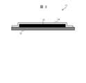
図1は、実施形態に係るウェアラブルセンサ1の外観を示す。Figure 1 shows the external appearance of a wearable sensor 1 according to an embodiment.
図1に示したように、ウェアラブルセンサ1は、センサグローブやセンサ組込手袋とも称される、薄手の作業手袋の指先にフィルム状の圧力センサ11が組み込まれた手袋型のウェアラブルセンサである。圧力センサ11は、ウェアラブルセンサ1の指先の腹側を中心とした領域に組み込まれており、ウェアラブルセンサ1が装着者の手に装着されると、装着者の指先の形状に沿ってその形状を変形させる。これにより、ウェアラブルセンサ1は、装着者の手先によくフィットする。その結果、ウェアラブルセンサ1の装着者は、実際の製造現場においても作業の支障にならない良好な装着感を得ることができる。As shown in FIG. 1, the wearable sensor 1 is a glove-type wearable sensor in which a film-
また、ウェアラブルセンサ1は、指先に組み込まれている圧力センサ11が後述する特徴を備えていることによって、ウェアラブルセンサ1の装着者の指先に印加される圧力を適切に検出することができる。In addition, the wearable sensor 1 can properly detect the pressure applied to the fingertips of the wearer of the wearable sensor 1 by having the
すなわち、ウェアラブルセンサ1は、上述の特徴を備えることにより、装着者の手先によくフィットし、かつ、装着者の指先への圧力印加を精度よく検出することができる。In other words, by having the above-mentioned characteristics, the wearable sensor 1 fits well on the wearer's hand and can accurately detect pressure applied to the wearer's fingertips.
なお、図1に例示したウェアラブルセンサ1は、理解を容易にするために、圧力センサ11が人差し指の指先に組み込まれているものとして図示しているが、無論、圧力センサ11は、他の指の指先に組み込まれていてもよいし、複数の指の指先に組み込まれていてもよい。また、ウェアラブルセンサ1の指先に組み込まれた圧力センサ11の具体的な位置や向きなどは、着用者が行う作業中の動作の内容や着用者の身体的特徴に合わせて適宜に決定されればよい。For ease of understanding, the wearable sensor 1 illustrated in FIG. 1 is shown with the
次に、ウェアラブルセンサ1に組み込まれている圧力センサについて説明する。Next, we will explain the pressure sensor built into the wearable sensor 1.
図2は、実施形態に係る圧力センサ11の構成例を示す。Figure 2 shows an example configuration of the
また、図3は、実施形態に係る圧力センサ11のフレキシブル基板12の構成例を示す。FIG. 3 also shows an example of the configuration of the
図2に示した圧力センサ11は、一つのフレキシブル基板12、一つの感圧素子13、および、一つの保護フィルム14を含む。フレキシブル基板12は、図3に示したように、高分子厚膜フィルム(Polymer Thick Film; PTF)の内部に銅箔などの導電性の金属箔からなるシート状の電極15が設けられたものである。フレキシブル基板12に設けられたこの電極15は、図3に示したように、上下方向から見ると、略くし状に形成されている。フレキシブル基板12の上面側には、シート状の感圧素子13が当該フレキシブル基板12に対して略平行に設けられている。この感圧素子13は、フレキシブル基板12の電極15と電気的に接続されている。そして、感圧素子13の上面側には絶縁樹脂からなる保護フィルム14が配置されており、圧力センサ11の周縁部において、フレキシブル基板12の上面と保護フィルム14の下面とが接着固定されている。The
すなわち、感圧素子13は、フレキシブル基板12の上面と保護フィルム14の下面とによって形成されている圧力センサ11の内部空間に、下面がフレキシブル基板12の上面と対面し、上面が保護フィルム14の下面と対面する体勢で封入されている。そして、感圧素子13の下面とフレキシブル基板12の上面との間、および、感圧素子13の上面と保護フィルム14の下面との間は、互いに接着固定されている。That is, the pressure-
圧力センサ11が組み込まれているウェアラブルセンサ1の指先に各種圧力が印加されると、圧力センサ11が変形し、圧力センサ11の内部の感圧素子13もそれに伴って変形する。感圧素子13の内部には、ウェアラブルセンサ1が未装着の状態、すなわち初期状態においては導電性を有する微粒子がおよそ等間隔を保って均一に存在している。しかしながら、感圧素子13が変形すると、内部に存在する微粒子間の距離が部分的に伸縮する。そのため、通電時に感圧素子13の内の電気抵抗値が変化する。これにより、ウェアラブルセンサ1は、当該指先に印加された各種圧力を検出することができる。When various pressures are applied to the fingertip of the wearable sensor 1 incorporating the
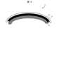
圧力センサ11は、上述したように、感圧素子13の下面とフレキシブル基板12の上面、および、感圧素子13の上面と保護フィルム14の下面が接着固定されている。そのため、図4に例示したように圧力センサ11は、長手方向における両端が下方に曲がるように変形すると、フレキシブル基板12、感圧素子13、および、保護フィルム14の物性や機械的特性の違いに起因して、(1)変形時に感圧素子13自身に作用する応力、の他に、(2)保護フィルム14から印加される応力や、(3)フレキシブル基板12から印加される応力が、感圧素子13に作用する。これにより、圧力センサ11が検出する圧力は、補正処理を加えていない素の状態では、上記(1)~(3)のいずれか、もしくは、上記(1)~(3)を組み合わせたものとなる。こうした課題の存在により、圧力センサ11は、ウェアラブルセンサ1の装着時や、装着後間もない時点では、真に検出すべき圧力のみを的確に反映したセンサ信号を発することができない。As described above, the
そこで、本実施形態のセンシングデータ補正システム100は、圧力センサ11が取得したセンサ値を表すデータ(以下、「センシングデータ」と称する)について補正処理を実行する。センシングデータ補正システム100が実行するこの処理を、センシングデータ補正処理と称する。これにより、ウェアラブルセンサ1の装着時に、圧力センサ11においてフレキシブル基板12や保護フィルム14との関係で感圧素子13に作用していた不要な応力の影響を取り除くことができる。The sensing
図5は、実施形態に係るセンシングデータ補正システム100の構成例を示す。Figure 5 shows an example configuration of a sensing
図5に示したシステム100の各構成要素は、CPU(Central Processing Unit)および各種コプロセッサ(Co-processor)などのプロセッサデバイス(以下、単に「プロセッサ」とも称する)、メモリやストレージといった記憶装置、それらを連結する有線または無線の通信線やインターフェース装置を含むハードウェアと、記憶装置に記憶され、演算器に処理命令を供給するソフトウェアによって実現される。Each component of the
記憶装置は、少なくともセンシングデータ補正プログラムを記憶する。センシングデータ補正プログラムは、センシングデータの補正のためのコンピュータプログラムである。センシングデータ補正プログラムがプロセッサにより実行されることで、後述するセンシングデータの補正のための各処理が行われる。The storage device stores at least a sensing data correction program. The sensing data correction program is a computer program for correcting sensing data. When the sensing data correction program is executed by the processor, each process for correcting the sensing data, which will be described later, is performed.
なお、センシングデータ補正プログラムは、デバイスドライバ、オペレーティングシステム、それらの上位層に位置する各種アプリケーションプログラム、また、これらのプログラムに共通機能を提供するライブラリによって構成されてもよい。以下に説明する各ブロックは、ハードウェア単位の構成ではなく、機能単位のブロックを示している。The sensing data correction program may be composed of a device driver, an operating system, various application programs located at higher layers, and libraries that provide common functions to these programs. Each block described below represents a functional block, not a hardware configuration.
センシングデータ補正システム100は、データ処理部110、データ記録部120、ユーザーインターフェース部130および通信部(不図示)の各機能ブロックを有する。The sensing
データ処理部110は、ユーザーインターフェース部130が検出したユーザーの操作入力、通信部により取得されたデータ、およびデータ記録部120が格納するプログラムやデータに基づいて各種データ処理を実行する。データ処理部110は、ユーザーインターフェース部130、通信部およびデータ記録部120のインターフェースとしても機能する。The
データ処理部110は、データ補正部140を機能ブロックとして有する。データ補正部140は、センシングデータの補正のための各種処理を実行する。データ補正部140が実行するこの処理を、センシングデータ補正処理と称する。センシングデータ補正処理の詳細は、図6に関連して後述する。The
また、データ処理部110は、ウェアラブルセンサ1の装着者、すなわち作業者の特徴抽出のための各種処理を実行する作業者特徴抽出部150を機能ブロックとして有していてもよい。これにより、センシングデータ補正システム100は、ウェアラブルセンサ1の装着者である各作業者の動作上の特徴や身体的特徴など(以下、「作業者特徴」と称する)を抽出してもよい。データ記録部120は、作業者特徴抽出部150が抽出した作業者毎の作業者特徴を表すデータ(以下、「作業者特徴データ」と称する)を記憶装置に記録してもよい。The
データ処理部110は、所定のプログラムを実行することによって、これらの機能ブロックを実現することができる。The
データ記録部120は、例えばRAMやフラッシュメモリなどの記憶装置を用いて構成されており、データ処理部110に各種処理命令を供給するプログラム、およびデータ処理部110が実行する処理において用いられる各種情報を表すデータを記憶装置に記憶させる。データ処理部110は、これらの情報を記憶装置に読み書きすることで、前述のデータ補正部140および作業者特徴抽出部150の各機能ブロックを実現することができる。The
ユーザーインターフェース部130は、ユーザーからの入力操作を受け付けるほか、画像表示や音声出力など、ユーザーインターフェースに関する処理を担当する。ユーザーインターフェース部130は、入力部(不図示)および出力部(不図示)の各機能ブロックを有する。入力部は、ユーザーからの各種操作を検出する。入力部は、例えばキーボードやポインティングデバイス、タッチパネルなどを用いて構成される。出力部は、センサデータが表すセンサ値を表示装置に表示させるほか、表示装置への各種画面の表示や音声出力などを実行する。表示装置は、例えば液晶ディスプレイやタッチスクリーンなどを用いて構成される。The
通信部(不図示)は、有線または無線で接続された受信機4からセンサデータを受信して、データ処理部110およびデータ記録部120に送信する。また、通信部は、インターネット(通信ネットワークの一例)を介して行われる、センシングデータ補正システム100のユーザーが保有するユーザー端末や、サーバ装置などの他の機器との通信処理を担当する。通信部は、例えばNIC(Network Interface Card)やHBA(Host Bus Adapter)などを用いて構成される。The communication unit (not shown) receives sensor data from the receiver 4 connected by wire or wirelessly, and transmits it to the
本実施形態では、センシングデータ補正システム100の各機能が一台のコンピュータ装置により一体的に実現されているものとして説明した。しかしながら、これらの各機能は相互に接続された複数台のコンピュータ装置またはサーバ装置によって実現されてもよい。また、センシングデータ補正システム100は、ラップトップPCなどの汎用コンピュータ装置と、これにインストールされたウェブブラウザとを含む構成であってもよいし、ウェブサーバや各種携帯機器を含む構成であってもよい。In this embodiment, the functions of the sensing
ウェアラブルセンサ1は送信機3と接続されており、ウェアラブルセンサ1は、取得したセンサ値を表すセンサ信号を送信機3に向けて発信する。送信機3は、センサ信号を受信すると、当該センサ信号を受信機4に対して送信する。受信機4は、センサ信号を受信すると、当該センサ信号からセンサデータを抽出して、前述したように、当該センサデータをセンシングデータ補正システム100の通信部に送信する。なお、センサ信号は、アナログ信号であってもよく、また、デジタル信号であってもよい。センサ信号がアナログ信号である場合、例えば受信機4がD/Aコンバータ(Digital-Analog Converter; DAC)を備えることによって、アナログ信号をデジタル信号へと適宜に変換してもよい。The wearable sensor 1 is connected to the
また、ウェアラブルセンサ1に加えて、例えば、作業対象物50を掴む、離すといった動作をはじめとする、作業者の作業中の動作を撮影する据付けカメラ2がセンサとして送信機3と接続されていてもよい。この場合、センシングデータ補正システム100は、据付けカメラ2が取得した映像データを扱うことができてもよい。In addition to the wearable sensor 1, a mounted camera 2 that captures the actions of the worker while working, such as grasping and releasing the
次に、センシングデータ補正システム100が実行するセンシングデータ補正処理の流れについて説明する。Next, we will explain the flow of the sensing data correction process performed by the sensing
図6は、センシングデータ補正処理の流れの一例を示すフローチャートである。Figure 6 is a flowchart showing an example of the flow of the sensing data correction process.
本実施形態で行われるセンシングデータ補正処理は、ウェアラブルセンサ1の設定時に行われる処理(ステップS601~S605)と、当該ウェアラブルセンサ1の実使用時に行われる処理(ステップS606~S610)とから構成されている。まず、ウェアラブルセンサ1の設定時の処理の流れは次の通りである。The sensing data correction process performed in this embodiment is composed of processes performed when setting up the wearable sensor 1 (steps S601 to S605) and processes performed when the wearable sensor 1 is actually used (steps S606 to S610). First, the process flow when setting up the wearable sensor 1 is as follows.
ステップS601において、データ処理部110は、センシングデータ補正システム100を起動させる入力操作をユーザーインターフェース部130が検出すると、センシングデータ補正システム100を起動させる。この段階のセンサ信号と時間の経過との関係は、図6においてグラフXに例示した通りである。なお、図6に例示したグラフX~Zにおいて、縦軸はセンサ信号が表す圧力値を示しており、横軸は時間を示している。データ処理部110は、ステップS601における処理が完了すると、ステップS602に進む。In step S601, when the
ステップS602において、ウェアラブルセンサ1が作業者に装着されたことにより、ウェアラブルセンサ1の指先に組み込まれた圧力センサ11が曲がることによる圧力反応によって当該ウェアラブルセンサ1が発するセンサ信号が図6においてグラフYのようにさらに持ち上がると、データ処理部110は、この持ち上がったセンサ信号を表すセンシングデータを取得する。データ処理部110は、ステップS602における処理が完了すると、ステップS603に進む。In step S602, when the wearable sensor 1 is worn by the worker, the
ステップS603において、データ処理部110は、図6においてグラフYのように持ち上がったセンサ信号を表すセンシングデータを取得すると、データ補正部140により、初期状態設定をオンにする。これにより、ウェアラブルセンサ1の初期状態設定がオンになる。なお、データ補正部140は、ウェアラブルセンサ1の初期状態設定を自動的にオンにせずに、ウェアラブルセンサ1の初期状態設定をオンにする入力操作をユーザーインターフェース部130が検出した場合に、ウェアラブルセンサ1の初期状態設定をオンにしてもよい。データ処理部110は、ステップS603における処理が完了すると、ステップS604に進む。In step S603, when the
ステップS604において、データ処理部110は、データ補正部140により、オフセットをキャンセルする処理を実行する。これにより、図6においてグラフYのように持ち上がっていたセンサ信号を表すセンシングデータについて、オフセットがキャンセルされて、図6にグラフZとして例示したように、当該センシングデータが表す圧力値が0に補正される。その結果、ウェアラブルセンサ1の装着時に当該ウェアラブルセンサ1に組み込まれた圧力センサ11が曲がることによる不要な圧力反応を表すセンシングデータが適切に補正される。データ処理部110は、ステップS604における処理が完了すると、ステップS605に進む。In step S604, the
ステップS605において、データ処理部110は、ウェアラブルセンサ1の装着時の入力オフセットがステップS604でキャンセルされると、データ補正部140により、初期状態設定をオフにする。これにより、ウェアラブルセンサ1の初期状態設定がオフになる。なお、データ補正部140は、ウェアラブルセンサ1の初期状態設定を自動的にオフにせずに、ウェアラブルセンサ1の初期状態設定をオフにする入力操作をユーザーインターフェース部130が検出した場合に、ウェアラブルセンサ1の初期状態設定をオフにしてもよい。データ処理部110は、ステップS605における処理が完了すると、設定時に係る処理を終了する。In step S605, when the input offset when the wearable sensor 1 is attached is canceled in step S604, the
設定時に係る処理はここまでであり、以降は実使用時に係る処理となる。データ処理部110は、ステップS605における処理が完了すると、次いで実使用時に係る処理を行うために、ステップS606に進む。This is the end of the processing related to the setup, and from here on, processing related to actual use will take place. When the processing in step S605 is completed, the
ステップS606において、データ処理部110は、ウェアラブルセンサ1の使用開始をユーザーインターフェース部130が検出すると、実使用時に係る処理に移行する。データ処理部110は、ステップS606における処理が完了すると、ステップS607に進む。In step S606, when the
ステップS607において、データ処理部110は、データ補正部140により、ウェアラブルセンサ1によって取得された圧力値が0よりも小さいか否かを判定する処理を実行する。当該圧力値が0よりも小さいと判定した場合(ステップS607:Y)は、当該圧力値を表すセンシングデータを補正するためにステップS608に進み、当該圧力値が0以上であると判定した場合(ステップS607:N)は、ステップS609に進む。In step S607, the
ステップS608において、データ処理部110は、データ補正部140により、ステップS607で0よりも小さいと判定された圧力値を表すセンシングデータを補正する。データ補正部140は、当該センシングデータが表す圧力値を0に補正する。これにより、ウェアラブルセンサ1の装着当初に当該ウェアラブルセンサ1の装着者である作業者が指で圧力センサ11を押さえつけることで生じる一時的な応力緩和による信号レベルの低下の影響を取り除くことができる。データ処理部110は、ステップS608における処理が完了すると、ステップS610に進む。データ処理部110は、ステップS608における処理が完了すると、ステップS610に進む。In step S608, the
ステップS609において、データ処理部110は、ステップS607で0以上であると判定された圧力値を表すセンシングデータについては、データ補正部140による補正処理を行わずに、そのままステップS610に進む。In step S609, the
ステップS610において、データ処理部110は、センシングデータ補正システム100を終了させるか否かを判定する処理を実行する。センシングデータ補正システム100を終了させると判定した場合(ステップS610:Y)は、図6のフローチャートに示すセンシングデータ補正処理を終了する。他方、未だセンシングデータ補正システム100を終了させないと判定した場合(ステップS610:N)は、再びステップS607に戻り、引き続きセンシングデータ補正処理を続行する。In step S610, the
本実施形態のセンシングデータ補正システム100は、上記のセンシングデータ補正処理を実行することにより、センシングデータから、(1)ウェアラブルセンサ1が作業者に装着されたことによってウェアラブルセンサ1の指先に組み込まれた圧力センサ11が曲がることによる圧力反応の影響と、(2)ウェアラブルセンサ1の装着当初に当該ウェアラブルセンサ1の装着者である作業者が指で圧力センサ11を押さえつけることで生じる一時的な応力緩和による信号レベルの低下の影響とを取り除くことができる。その結果、センシングデータ補正システム100は、薄手の作業手袋の指先にフィルム状の圧力センサが組み込まれた手袋型のウェアラブルセンサから取得したセンシングデータについて、真に検出すべき圧力のみを的確に反映したセンシングデータに補正することができる。By executing the above-mentioned sensing data correction process, the sensing
なお、本発明は上記実施形態に限定されるものではなく、その要旨を逸脱しない範囲内で、任意の構成要素を用いて実施可能である。The present invention is not limited to the above embodiment, and can be implemented using any components without departing from the spirit of the invention.
上記の実施形態や変形例はあくまで一例であり、発明の特徴が損なわれない限り、本発明はこれらの内容に限定されるものではない。また、上記では種々の実施形態や変形例を説明したが、本発明はこれらの内容に限定されるものではない。本発明の技術的思想の範囲内で考えられるその他の態様も本発明の範囲内に含まれる。The above embodiments and modifications are merely examples, and the present invention is not limited to these contents as long as the characteristics of the invention are not impaired. In addition, although various embodiments and modifications have been described above, the present invention is not limited to these contents. Other aspects that are conceivable within the scope of the technical ideas of the present invention are also included in the scope of the present invention.
1:ウェアラブルセンサ
11:圧力センサ
12:フレキシブル基板
13:感圧素材
14:保護フィルム
15:電極(配線パターン)
50:作業対象物
100:センシングデータ補正システム
110:データ処置部
120:データ記録部
130:ユーザーインターフェース部
140:データ補正部
150:作業者特徴抽出部
2:据付けカメラ
3:送信機
4:受信機 1: Wearable sensor 11: Pressure sensor 12: Flexible substrate 13: Pressure-sensitive material 14: Protective film 15: Electrode (wiring pattern)
50: Work object 100: Sensing data correction system 110: Data processing unit 120: Data recording unit 130: User interface unit 140: Data correction unit 150: Worker feature extraction unit 2: Installed camera 3: Transmitter 4: Receiver
Claims (4)
Translated fromJapanese前記センシングデータを補正するデータ補正部を備え、
三次元直交座標系における三つの座標軸方向をそれぞれ上下方向、前記圧力センサの長手方向、および前記圧力センサの幅方向として、
前記圧力センサは、
一つのフレキシブル基板と、一つのシート状の感圧素子と、一つの保護フィルムとが上下方向に積層されてなり、
前記フレキシブル基板の上面と前記感圧素子の下面との間、および、前記感圧素子の上面と前記保護フィルムの下面との間がそれぞれ接着固定されており、
前記データ補正部は、前記ウェアラブルセンサの装着当初に当該ウェアラブルセンサから取得したセンシングデータを補正するセンシングデータ補正処理を実行する、
センシングデータ補正システム。 A sensing data correction system for correcting sensing data acquired from a glove-type wearable sensor having a film-type pressure sensor incorporated in a fingertip, comprising:
a data correction unit that corrects the sensing data,
The three coordinate axis directions in the three-dimensional orthogonal coordinate system are defined as the up-down direction, the longitudinal direction of the pressure sensor, and the width direction of the pressure sensor,
The pressure sensor includes:
A flexible substrate, a sheet-like pressure-sensitive element, and a protective film are stacked in the vertical direction.
an upper surface of the flexible substrate and a lower surface of the pressure-sensitive element, and an upper surface of the pressure-sensitive element and a lower surface of the protective film are respectively adhesively fixed to each other;
The data correction unit executes a sensing data correction process to correct sensing data acquired from the wearable sensor at the beginning of wearing the wearable sensor.
Sensing data correction system.
前記センシングデータ補正処理は、前記ウェアラブルセンサの装着時に当該ウェアラブルセンサから取得したセンシングデータについて、オフセットをキャンセルする処理を含む、
センシングデータ補正システム。 2. The sensing data correction system according to claim 1,
The sensing data correction process includes a process of canceling an offset of sensing data acquired from the wearable sensor when the wearable sensor is worn.
Sensing data correction system.
前記センシングデータ補正処理は、
前記センシングデータが表す圧力値が0よりも小さい場合、当該センシングデータが表す圧力値を0に補正する処理を含む、
センシングデータ補正システム。 2. The sensing data correction system according to claim 1,
The sensing data correction process includes:
When the pressure value represented by the sensing data is smaller than 0, a process of correcting the pressure value represented by the sensing data to 0 is included.
Sensing data correction system.
前記コンピュータは、前記センシングデータを補正するデータ補正部を備え、
三次元直交座標系における三つの座標軸方向をそれぞれ上下方向、前記圧力センサの長手方向、および前記圧力センサの幅方向として、
前記圧力センサは、
一つのフレキシブル基板と、一つのシート状の感圧素子と、一つの保護フィルムとが上下方向に積層されてなり、
前記フレキシブル基板の上面と前記感圧素子の下面との間、および、前記感圧素子の上面と前記保護フィルムの下面との間がそれぞれ接着固定されており、
前記データ補正部は、前記ウェアラブルセンサの装着当初に当該ウェアラブルセンサから取得したセンシングデータを補正するセンシングデータ補正処理を実行する、
センシングデータ補正方法。 A sensing data correction method for correcting sensing data acquired from a glove-type wearable sensor having a film-type pressure sensor incorporated in a fingertip by a computer, comprising:
The computer includes a data correction unit that corrects the sensing data,
The three coordinate axis directions in the three-dimensional orthogonal coordinate system are defined as the up-down direction, the longitudinal direction of the pressure sensor, and the width direction of the pressure sensor,
The pressure sensor includes:
A flexible substrate, a sheet-like pressure-sensitive element, and a protective film are stacked in the vertical direction.
an upper surface of the flexible substrate and a lower surface of the pressure-sensitive element, and an upper surface of the pressure-sensitive element and a lower surface of the protective film are respectively adhesively fixed to each other;
The data correction unit executes a sensing data correction process to correct sensing data acquired from the wearable sensor at the beginning of wearing the wearable sensor.
Sensing data correction method.
Priority Applications (3)
| Application Number | Priority Date | Filing Date | Title |
|---|---|---|---|
| JP2022161783AJP2024055123A (en) | 2022-10-06 | 2022-10-06 | Sensing data correction system and sensing data correction method |
| CN202311272560.8ACN117848549A (en) | 2022-10-06 | 2023-09-28 | Sensing data correction system and sensing data correction method |
| US18/376,121US20240118151A1 (en) | 2022-10-06 | 2023-10-03 | Sensing data correction system and sensing data correction method |
Applications Claiming Priority (1)
| Application Number | Priority Date | Filing Date | Title |
|---|---|---|---|
| JP2022161783AJP2024055123A (en) | 2022-10-06 | 2022-10-06 | Sensing data correction system and sensing data correction method |
Publications (2)
| Publication Number | Publication Date |
|---|---|
| JP2024055123Atrue JP2024055123A (en) | 2024-04-18 |
| JP2024055123A5 JP2024055123A5 (en) | 2025-03-18 |
Family
ID=90540795
Family Applications (1)
| Application Number | Title | Priority Date | Filing Date |
|---|---|---|---|
| JP2022161783APendingJP2024055123A (en) | 2022-10-06 | 2022-10-06 | Sensing data correction system and sensing data correction method |
Country Status (3)
| Country | Link |
|---|---|
| US (1) | US20240118151A1 (en) |
| JP (1) | JP2024055123A (en) |
| CN (1) | CN117848549A (en) |
- 2022
- 2022-10-06JPJP2022161783Apatent/JP2024055123A/enactivePending
- 2023
- 2023-09-28CNCN202311272560.8Apatent/CN117848549A/enactivePending
- 2023-10-03USUS18/376,121patent/US20240118151A1/enactivePending
Also Published As
| Publication number | Publication date |
|---|---|
| CN117848549A (en) | 2024-04-09 |
| US20240118151A1 (en) | 2024-04-11 |
Similar Documents
| Publication | Publication Date | Title |
|---|---|---|
| CN107977110B (en) | Electronic device and method for obtaining fingerprint information | |
| US8686959B2 (en) | Touch screen multi-control emulator | |
| US11009949B1 (en) | Segmented force sensors for wearable devices | |
| CN105808009B (en) | A kind of pressure sensor, haptic feedback devices and relevant apparatus | |
| CN104866147A (en) | Capacitive Finger Navigation Module And Manufacturing Method Thereof | |
| JP2008203911A (en) | Pointing device and computer | |
| EP3657306B1 (en) | Handheld input apparatus | |
| CN107580134B (en) | Display method of mobile terminal and mobile terminal | |
| CN103605433A (en) | Multifunctional somatological input device | |
| JP7472262B2 (en) | Pen state detection circuit with configurable input/output model | |
| JP2024055123A (en) | Sensing data correction system and sensing data correction method | |
| CN108885556A (en) | control digital input | |
| KR101748570B1 (en) | Wearable data input device | |
| JP2024024440A (en) | Pen state detection circuit and method, and input system | |
| TWI728426B (en) | Emulate stylus pen | |
| CN114063824A (en) | Pressure sensing module, pressure sensing detection method and device and electronic equipment | |
| CN205540657U (en) | Pressure sensor, tactile feedback device and relevant device | |
| KR20160149403A (en) | Wearable data input device and method thereof | |
| JP7559969B2 (en) | Input device, input system and input method | |
| CN113805723B (en) | Touch processing method, device and touch system | |
| CN114327042B (en) | Detection glove, gesture tracking method, AR equipment and key pressing method | |
| CN113805722B (en) | Touch processing method, device and touch system | |
| US11874955B2 (en) | Electronic device | |
| CN116088374A (en) | Method, device, equipment, controller, and storage medium for collecting control instructions | |
| CN117251067A (en) | Touch system and touch method |
Legal Events
| Date | Code | Title | Description |
|---|---|---|---|
| A521 | Request for written amendment filed | Free format text:JAPANESE INTERMEDIATE CODE: A523 Effective date:20250310 | |
| A621 | Written request for application examination | Free format text:JAPANESE INTERMEDIATE CODE: A621 Effective date:20250310 |