JP2024044859A - POWER TRANSMISSION DEVICE, CONTROL METHOD FOR POWER TRANSMISSION DEVICE, AND PROGRAM - Google Patents
POWER TRANSMISSION DEVICE, CONTROL METHOD FOR POWER TRANSMISSION DEVICE, AND PROGRAMDownload PDFInfo
- Publication number
- JP2024044859A JP2024044859AJP2022150646AJP2022150646AJP2024044859AJP 2024044859 AJP2024044859 AJP 2024044859AJP 2022150646 AJP2022150646 AJP 2022150646AJP 2022150646 AJP2022150646 AJP 2022150646AJP 2024044859 AJP2024044859 AJP 2024044859A
- Authority
- JP
- Japan
- Prior art keywords
- power
- antenna
- state
- value
- control
- Prior art date
- Legal status (The legal status is an assumption and is not a legal conclusion. Google has not performed a legal analysis and makes no representation as to the accuracy of the status listed.)
- Pending
Links
Images


Classifications
- H—ELECTRICITY
- H02—GENERATION; CONVERSION OR DISTRIBUTION OF ELECTRIC POWER
- H02J—CIRCUIT ARRANGEMENTS OR SYSTEMS FOR SUPPLYING OR DISTRIBUTING ELECTRIC POWER; SYSTEMS FOR STORING ELECTRIC ENERGY
- H02J50/00—Circuit arrangements or systems for wireless supply or distribution of electric power
- H02J50/80—Circuit arrangements or systems for wireless supply or distribution of electric power involving the exchange of data, concerning supply or distribution of electric power, between transmitting devices and receiving devices
- H—ELECTRICITY
- H02—GENERATION; CONVERSION OR DISTRIBUTION OF ELECTRIC POWER
- H02J—CIRCUIT ARRANGEMENTS OR SYSTEMS FOR SUPPLYING OR DISTRIBUTING ELECTRIC POWER; SYSTEMS FOR STORING ELECTRIC ENERGY
- H02J50/00—Circuit arrangements or systems for wireless supply or distribution of electric power
- H02J50/10—Circuit arrangements or systems for wireless supply or distribution of electric power using inductive coupling
- H02J50/12—Circuit arrangements or systems for wireless supply or distribution of electric power using inductive coupling of the resonant type
- H—ELECTRICITY
- H02—GENERATION; CONVERSION OR DISTRIBUTION OF ELECTRIC POWER
- H02J—CIRCUIT ARRANGEMENTS OR SYSTEMS FOR SUPPLYING OR DISTRIBUTING ELECTRIC POWER; SYSTEMS FOR STORING ELECTRIC ENERGY
- H02J50/00—Circuit arrangements or systems for wireless supply or distribution of electric power
- H02J50/20—Circuit arrangements or systems for wireless supply or distribution of electric power using microwaves or radio frequency waves
- H—ELECTRICITY
- H02—GENERATION; CONVERSION OR DISTRIBUTION OF ELECTRIC POWER
- H02J—CIRCUIT ARRANGEMENTS OR SYSTEMS FOR SUPPLYING OR DISTRIBUTING ELECTRIC POWER; SYSTEMS FOR STORING ELECTRIC ENERGY
- H02J50/00—Circuit arrangements or systems for wireless supply or distribution of electric power
- H02J50/60—Circuit arrangements or systems for wireless supply or distribution of electric power responsive to the presence of foreign objects, e.g. detection of living beings
- H—ELECTRICITY
- H02—GENERATION; CONVERSION OR DISTRIBUTION OF ELECTRIC POWER
- H02J—CIRCUIT ARRANGEMENTS OR SYSTEMS FOR SUPPLYING OR DISTRIBUTING ELECTRIC POWER; SYSTEMS FOR STORING ELECTRIC ENERGY
- H02J50/00—Circuit arrangements or systems for wireless supply or distribution of electric power
- H02J50/90—Circuit arrangements or systems for wireless supply or distribution of electric power involving detection or optimisation of position, e.g. alignment
Landscapes
- Engineering & Computer Science (AREA)
- Computer Networks & Wireless Communication (AREA)
- Power Engineering (AREA)
- Charge And Discharge Circuits For Batteries Or The Like (AREA)
Abstract
Translated fromJapaneseDescription
Translated fromJapanese本開示は、無線電力伝送の技術に関する。This disclosure relates to wireless power transmission technology.
無線電力伝送システムにおいて送電装置は、充電台等に載置された受電装置に対して送電を行う。一般的に、送電装置が有する送電アンテナと、受電装置が有する受電アンテナとが正対した状態で無線電力伝送が行われる。特許文献1には、送電コイルと受電コイルとの間に侵入した異物の検出処理や、送電コイルと受電コイルとの間の位置ずれの検出処理について開示されている。 In a wireless power transmission system, a power transmitting device transmits power to a power receiving device placed on a charging stand or the like. Generally, wireless power transmission is performed with a power transmitting antenna of a power transmitting device and a power receiving antenna of a power receiving device directly facing each other. Patent Document 1 discloses a process for detecting a foreign object that has entered between a power transmitting coil and a power receiving coil, and a process for detecting a positional deviation between a power transmitting coil and a power receiving coil.
従来の技術では、送電装置から受電装置への無線電力伝送において送電アンテナと受電アンテナとの電磁的な結合が弱い場合、適切に制御を行う方法が確立されていない。送電アンテナと受電アンテナとの電磁的な結合(以下、単に結合ともいう)が弱い場合とは、受電アンテナと送電アンテナとが正対しない場合や、受電アンテナと送電アンテナとの距離が所定の距離以上である場合等である。
本開示は、無線電力伝送において送電アンテナと受電アンテナとの電磁的な結合状態に対応した制御を可能とする技術の提供を目的とする。 In the conventional technology, when the electromagnetic coupling between the power transmitting antenna and the power receiving antenna is weak in wireless power transmission from a power transmitting device to a power receiving device, a method for appropriately controlling the weak electromagnetic coupling between the power transmitting antenna and the power receiving antenna (hereinafter, simply referred to as coupling) is not established when the power receiving antenna and the power transmitting antenna are not directly facing each other, when the distance between the power receiving antenna and the power transmitting antenna is equal to or greater than a predetermined distance, etc.
An object of the present disclosure is to provide a technique that enables control corresponding to the electromagnetic coupling state between a power transmitting antenna and a power receiving antenna in wireless power transmission.
本開示の実施形態に係る送電装置は、送電アンテナを介して受電装置に無線で送電する送電手段と、前記送電手段により複数の異なる条件で信号を出力して物体を検知する検知手段と、前記送電手段を制御する制御手段と、を備え、前記制御手段は、前記検知手段により前記受電装置が検知され、かつ前記送電アンテナと前記受電装置の受電アンテナとの電磁的な結合が予め定めた状態での電磁的な結合より弱い状態である場合に前記送電手段の制御を変更する。 A power transmission device according to an embodiment of the present disclosure includes: a power transmission device that wirelessly transmits power to a power receiving device via a power transmission antenna; a detection device that outputs a signal under a plurality of different conditions by the power transmission device to detect an object; control means for controlling a power transmission means, wherein the control means is configured such that the power reception device is detected by the detection means and the electromagnetic coupling between the power transmission antenna and the power reception antenna of the power reception device is in a predetermined state. The control of the power transmission means is changed when the electromagnetic coupling is weaker than the electromagnetic coupling.
本開示によれば、無線電力伝送において送電アンテナと受電アンテナとの電磁的な結合状態に対応した制御を可能とする技術を提供することができる。 According to the present disclosure, it is possible to provide a technology that enables control corresponding to the electromagnetic coupling state between a power transmitting antenna and a power receiving antenna in wireless power transmission.
以下、本開示の実施形態について、添付図面を参照しつつ詳細に説明する。実施形態では無線電力伝送システムを適用した無線充電システムを示す。一例として、無線充電の標準化団体Wireless Power Consortiumが策定する規格(以下、WPC規格と記す)に基づく無線電力伝送について説明する。 Embodiments of the present disclosure will be described in detail below with reference to the accompanying drawings. In the embodiment, a wireless charging system to which a wireless power transmission system is applied is shown. As an example, wireless power transmission based on a standard (hereinafter referred to as WPC standard) established by Wireless Power Consortium, a standardization organization for wireless charging, will be described.
[第1実施形態]
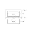
図1乃至図25を参照して、本実施形態について説明する。図1は無線充電システムの構成例を示す図である。本システムは、送電装置100、受電装置200、充電台300を備える。以下では、表記を簡潔にするため、受電装置200をRXと呼び、送電装置100をTXと呼ぶ場合がある。TXとRXの詳細な構成については図2および図3を用いて後述する。[First embodiment]
This embodiment will be described with reference to Fig. 1 to Fig. 25. Fig. 1 is a diagram showing a configuration example of a wireless charging system. This system includes a power transmitting
RXは、充電台300に載置された状態で、TXから受電して内蔵バッテリに充電を行う電子機器である。TXは、充電台300に載置されたRXに対して無線送電を行う電子機器である。充電台300はTXの一部を構成するので、以下ではRXが「充電台300に戴置された」ことを「TXに載置された」という場合がある。RXがTXから受電可能な空間的範囲を、図1にて点線枠400の範囲で模式的に示す。RXとTXは無線充電機能以外のアプリケーションを実行する機能を有しうる。例えば、RXはスマートフォンであり、TXはRXのバッテリを充電するためのアクセサリ機器である。ただし、この例に限定されることはない。 The RX is an electronic device that receives power from the TX and charges its built-in battery while being placed on the
次に図2を参照して、送電装置100の構成例について説明する。図2は送電装置100(TX)の構成例を示す機能ブロック図である。TXは、制御部101、電源部102、送電部103、第1通信部104、送電アンテナ(送電コイル)105、メモリ106、共振コンデンサ107、スイッチ部108、第2通信部109、ユーザインタフェース部110を有する。以下、ユーザインタフェースをUIと表記する。図2では各機能ブロック要素が別体として記載されているが、任意の複数の機能ブロック要素は同一チップ内に実装されてもよい。Next, referring to FIG. 2, an example of the configuration of the
制御部101は、メモリ106に記憶されている制御プログラムを実行することにより、TX全体を制御する。また、制御部101はTXにおける機器認証のための通信を含む送電制御を行う。さらに制御部101は、無線電力伝送以外のアプリケーションを実行するための制御を行うことが可能である。制御部101は、CPU(Central Processing Unit)またはMPU(MicroProcessor Unit)等の1つ以上のプロセッサーを含んで構成される。あるいは、制御部101は、特定用途向け集積回路(ASIC:Application Specific Integrated Circuit)等のハードウェアで構成されてもよい。また、制御部101は、所定の処理を実行するようにコンパイルされたFPGA(Field Programmable Gate Array)等のアレイ回路を含んで構成されてもよい。制御部101は、各種処理の実行中に記憶しておくべき情報をメモリ106に記憶させる処理や、タイマ(不図示)を用いた計時処理を実行することができる。The
電源部102は、各機能ブロック要素への電源供給を行う。電源部102は、例えば、商用電源への電源接続回路やバッテリを備える。バッテリは商用電源から供給される電力により蓄電される。The
送電部103は、電源部102から入力される直流電力または交流電力を、無線電力伝送に用いる周波数帯域の交流電力に変換し、交流電力を送電アンテナ105へ入力することによって、RXに受電させるための電磁波を発生させる。例えば、送電部103はインバータを備え、電源部102が供給する直流電圧を、ハーフブリッジ構成またはフルブリッジ構成のスイッチング回路で交流電圧に変換する。送電部103はブリッジを構成する複数のFET(Field Effect Transister)と、複数のFETのON/OFFを制御するゲートドライバを含む。 The
送電部103は、送電アンテナ105に入力する電圧(送電電圧)もしくは電流(送電電流)、またはその両方を調節することにより、出力させる電磁波の強度(送電電力)を制御する。送電電圧または送電電流の大小により電磁波の強弱(送電電力の強弱)が制御される。あるいは、送電部103は、送電部103が有するインバータに入力する電圧もしくは電流、またはその両方を調節することにより、出力させる電磁波の強度(送電電力)を制御する。このインバータに入力する電圧を、以下ではインバータ入力電圧と呼ぶ。また、このインバータに入力する電流を、以下ではインバータ入力電流と呼ぶ。インバータ入力電圧またはインバータ入力電流の大小により電磁波の強弱(送電電力の強弱)が制御される。あるいは、送電部103は、送電部103が有するインバータから出力される電圧もしくは電流、またはその両方を調節することにより、出力させる電磁波の強度(送電電力)を制御する。このインバータから出力される電圧を、以下ではインバータ出力電圧と呼ぶ。また、このインバータから出力される電流を、以下ではインバータ出力電流と呼ぶ。インバータ出力電圧またはインバータ出力電流の大小により電磁波の強弱(送電電力の強弱)が制御される。送電部103では、制御部101からの指示信号に基づいて、送電アンテナ105による送電の開始または停止、または出力させる電磁波の強度が制御されるように、交流周波数の電磁波の電力の出力制御が行われる。また、送電部103はWPC規格に対応した受電装置200の充電部(図3:206)に15ワット(W)の電力を出力するだけの電力供給能力があるものとする。The
第1通信部104は制御部101と送電部103に接続され、RXとの間でWPC規格に基づく送電制御のための通信を行う。第1通信部104は、送電アンテナ105から出力される電磁波の周波数偏移変調を行い、RXへ情報を伝送して通信を行う。また、第1通信部104は、RXが変調を行った送電アンテナ105から送電される電磁波を復調して、RXが送信した情報を取得する。第1通信部104による通信は、送電アンテナ105から送電される電磁波に通信用の信号が重畳されることにより行われる。 The
メモリ106は、制御プログラムの他に、TXおよびRXの状態に関する情報を記憶することができる。TXおよびRXの状態に関する情報とは送電電力値、受電電力値等である。TXの状態に関する情報は制御部101により取得される。RXの状態に関する情報はRXの制御部(図3:201)により取得され、第1通信部104、あるいは後述する第2通信部109が受信可能である。In addition to the control program, the
スイッチ部108は、共振コンデンサ107および送電アンテナ105の直列回路に対して並列に接続されている。制御部101は、スイッチ部108に制御信号を送信して、そのON/OFF制御を行う。送電アンテナ105は、共振コンデンサ107と接続されている。制御部101からの制御信号によりスイッチ部108がON状態になって短絡される場合、送電アンテナ105と共振コンデンサ107は直列共振回路を形成し、特定の周波数fAで共振する。このとき、送電アンテナ105と共振コンデンサ107、スイッチ部108が形成する閉回路に電流が流れる。一方、制御部101からの制御信号によってスイッチ部108はOFF状態になり、当該回路が開放されると、送電アンテナ105と共振コンデンサ107には送電部103から電力が供給される。The
第2通信部109は制御部101と接続され、RXとの間でWPC規格とは異なる規格による通信を行う。例えば第2通信部109は、送電アンテナ105とは異なるアンテナを用いてRX(図3の第2通信部212)と通信する。無線LAN(Local Area Network)、Bluetooth(登録商標) Low Energy(BLE)、NFC(Near Field Communication)が挙げられる。送電アンテナ105から送電する際に使用する周波数帯域と、第2通信部109が通信に使用する周波数帯域とは異なる。The
TXとRXとの通信に関し、TXは、複数の通信規格のうちの、いずれかを選択的に用いてRXとの通信を行ってもよい。下記に示す複数の通信を選択的に用いた通信形態が可能である。
・TXの第1通信部104とRXの第1通信部204(図3)との間で行われる、第1の規格(WPC規格)に基づく通信。
・TXの第2通信部109とRXの第2通信部212(図3)との間で行われる、第2の規格(WPC規格以外の規格)に基づく通信。 Regarding communication between TX and RX, TX may communicate with RX by selectively using any one of a plurality of communication standards. A communication form that selectively uses a plurality of communications described below is possible.
- Communication based on the first standard (WPC standard) performed between the
- Communication based on a second standard (standard other than the WPC standard) performed between the
UI部110は制御部101と接続され、ユーザに対する各種の出力を行う。各種の出力とは、画面表示、LED(Light Emitting Diode)の点滅や色の変化、スピーカーによる音声出力、TX本体の振動等の動作である。UI部110は液晶パネル、スピーカー、バイブレーションモータ等により実現される。The
次に図3を参照して、受電装置200の構成例について説明する。図3は、受電装置200(RX)の構成例を示すブロック図である。RXは、制御部201、UI部202、受電部203、第1通信部204、受電アンテナ205、充電部206、バッテリ207、メモリ208を有する。RXはさらに第1スイッチ部209、第2スイッチ部210、共振コンデンサ211、第2通信部212、第3スイッチ部213を有する。本実施形態では図3の機能ブロック要素を個別の要素とする例を示すが、複数の機能ブロック要素を1つのハードウェアモジュールとして実現してもよい。 Next, a configuration example of the
制御部201は、メモリ208に記憶されている制御プログラムを実行することによりRXの各機能ブロック要素を制御する。さらに、制御部201は、無線電力伝送以外のアプリケーションを実行するための制御を行うことができる。制御部201はCPUまたはMPU等の1つ以上のプロセッサーを含んで構成される。また、制御部201が実行しているOS(Operating System)との協働によりRX全体(例えばスマートフォン全体)を制御することができる。あるいは、制御部201は、ASIC等のハードウェアで構成されるか、または所定の処理を実行するようにコンパイルされたFPGA等のアレイ回路を含んで構成される。制御部201は、各種処理の実行中に記憶しておくべき情報をメモリ208に記憶させ、また、タイマ(不図示)を用いた計時処理の実行が可能である。 The
UI部202は制御部201と接続され、ユーザに対する各種の出力を行う。各種の出力とは、画面表示、LED(Light Emitting Diode)の点滅や色の変化、スピーカーによる音声出力、RX本体の振動等の動作である。UI部202は液晶パネル、スピーカー、バイブレーションモータ等により実現される。 The
受電部203は、受電アンテナ(受電コイル)205を介して、TXの送電アンテナ105から放射された電磁波に基づく電磁誘導により生じた交流電力(交流電圧および交流電流)を受電する。そして、受電部203は、交流電力を直流または所定周波数の交流電力に変換して充電部206に電力を供給する。充電部206はバッテリ207の充電を行う。受電部203は、RXにおける負荷に対して電力の供給に必要な整流部(整流器、整流回路)および電圧制御部を含む。整流部は、受電アンテナ205を介して受電した、送電アンテナからの交流電圧および交流電流を直流電圧および直流電流に変換する。この直流電圧を、以下では整流部出力電圧と呼ぶ。またこの直流電流を、以下では整流部出力電流と呼ぶ。電圧制御部は、整流部が出力する直流電圧(整流部出力電圧)のレベルを所定レベルに変換する。所定レベルとは、制御部201および充電部206等の動作が可能な直流電圧のレベルである。受電部203は、充電部206からバッテリ207への充電用の電力を供給する。受電部203は充電部206に15ワットの電力を出力するだけの電力供給能力があるものとする。 The
第1通信部204は、TXが有する第1通信部104との間で、WPC規格に基づく受電制御のための通信を行う。第1通信部204は受電アンテナ205と制御部201に接続されている。第1通信部204は、受電アンテナ205から入力された電磁波を復調してTXから送信された情報を取得する。第1通信部204は、入力された電磁波に対して負荷変調または振幅変調を行って、TXへ送信すべき情報に関する信号を電磁波に重畳することにより、TXとの間で通信を行う。The
メモリ208は、制御プログラムの他に、TXおよびRXの状態に関する情報等を記憶する。RXの状態に関する情報は制御部201により取得される。またTXの状態に関する情報はTXの制御部101により取得され、第1通信部204または後述する第2通信部212により受信することができる。In addition to the control program, the
第2通信部212は制御部201と接続され、TXとの間でWPC規格とは異なる規格による通信を行う。例えば第2通信部212は、受電アンテナ205とは異なるアンテナを用いてTX(図2の第2通信部109)と通信する。無線LAN(Local Area Network)、Bluetooth(登録商標) Low Energy(BLE)、NFC(Near Field Communication)が挙げられる。受電アンテナ205で受電する際に使用する周波数帯域と、第2通信部212が通信に使用する周波数帯域とは異なる。The
TXとRXとの通信に関し、RXは、複数の通信規格のうちの、いずれかを選択的に用いてTXとの通信を行ってもよい。下記に示す複数の通信を選択的に用いた通信形態が可能である。
・TXの第1通信部104とRXの第1通信部204との間で行われる、第1の規格(WPC規格)に基づく通信。
・TXの第2通信部109とRXの第2通信部212との間で行われる、第2の規格(WPC規格以外の規格)に基づく通信。 Regarding the communication between the TX and the RX, the RX may selectively use any one of a plurality of communication standards to communicate with the TX. The following communication forms selectively using a plurality of communications are possible.
Communication based on the first standard (WPC standard) between the
Communication based on a second standard (a standard other than the WPC standard) between the
第1スイッチ部209は充電部206とバッテリ207との間に設けられており、制御部201により制御される。第1スイッチ部209は、受電部203が受電した電力をバッテリ207に供給するか否かを制御する機能と、負荷の大きさを制御する機能を有する。制御部201によって第1スイッチ部209がOFF状態となって開放される場合、受電部203が受電した電力はバッテリ207に供給されない。制御部201により第1スイッチ部209がON状態となって短絡される場合、受電部203が受電した電力がバッテリ207に供給される。 The
図3の例では第1スイッチ部209が充電部206とバッテリ207との間に配置されているが、第1スイッチ部209は受電部203と充電部206との間に配置されてもよい。あるいは第1スイッチ部209は、受電アンテナ205と共振コンデンサ211、および第2スイッチ部210が形成する閉回路と、受電部203との間に配置されてもよい。この場合、第1スイッチ部209は、受電アンテナ205が受電した電力を受電部203に供給するか否かを制御する機能を有する。3, the
また、図3の例では第1スイッチ部209が1つの機能ブロック要素として記載されているが、第1スイッチ部209を充電部206または受電部203の一部として実現することが可能である。また、第1スイッチ部209が充電部206とバッテリ207との間に直列に挿入されている構成に限定されず、第1スイッチ部209は充電部206とバッテリ207との間に並列に挿入されてもよい。この場合、制御部201により第1スイッチ部209がOFF状態となって開放される場合、受電部203が受電した電力はバッテリ207に供給される。制御部201により第1スイッチ部209がON状態となって短絡される場合、受電部203が受電した電力はバッテリ207に供給されない。 Further, in the example of FIG. 3, the
受電部203の入力側にて第2スイッチ部210は共振コンデンサ211と並列に接続されている。共振コンデンサ211は第3スイッチ部213を介して受電アンテナ205に接続されている。第2スイッチ部210と第3スイッチ部213は、制御部201により制御される。第3スイッチ部213は、受電アンテナ205の端子を開放にするか否かを制御する機能を有する。制御部201により第3スイッチ部213がOFF状態となる場合、受電アンテナ205の端子は開放状態になる。制御部201により第3スイッチ部213がON状態となる場合、受電アンテナ205は共振コンデンサ211を介して受電部203と接続される。 On the input side of the
制御部201により第3スイッチ部213がON状態となり、第2スイッチ部210がON状態となって短絡される場合、受電アンテナ205と共振コンデンサ211は直列共振回路を形成し、特定の周波数fBで共振する。受電アンテナ205、共振コンデンサ211、第2スイッチ部210が形成する閉回路に電流が流れ、受電部203に電流は流れない。そして第2スイッチ部210がOFF状態となって当該回路が開放されると、受電アンテナ205と共振コンデンサ211により受電された電力は、受電部203へ供給される。なお、図3の例に限定されることなく、第2スイッチ部210は、受電アンテナ205と共振コンデンサ211との間に配置されてもよい。第3スイッチ部213がON状態であって、第2スイッチ部210がON状態である場合、受電アンテナ205の端子は短絡される。また、第3スイッチ部213は、共振コンデンサ211と受電部203との間に配置されてもよい。 When the
本システムにてTXとRXは、送電アンテナ105と受電アンテナ205との間でWPC規格に基づく無線電力伝送を行う。WPC規格では、受電装置200が送電装置100から受電する際に保証される電力の大きさが、Guaranteed Load Power(以下、「GP」と記す)と呼ばれる値によって規定される。例えばGPは、受電装置200と送電装置100との位置関係が変動したことにより受電アンテナ205と送電アンテナ105との結合が弱くなり、電力伝送効率が低下したとしても、受電装置200の負荷への出力が保証される電力値を示す。受電装置200の負荷は図3の充電部206、バッテリ207等であり、GPの値は、受電部203から出力されることが保証される電力量に相当する。あるいは、GPの値は、受電部203が有する整流部から出力されることが保証される電力量に相当する。例えばGPの値を5(ワット)として、受電アンテナ205と送電アンテナ105との位置関係が変動した場合を想定する。この場合、電力伝送効率が低下したとしても、送電装置100は、受電装置200の負荷へ5ワットを出力することができるように送電制御を行う。また、GPは送電装置100と受電装置200とが行う交渉により決定される。なお、GPに限らず、送電装置と受電装置とが互いに交渉を行うことにより決定される電力で送受電が行われる構成において、本実施形態を適用可能である。In this system, TX and RX perform wireless power transmission based on the WPC standard between the transmitting
また、送電装置100から受電装置200への送電を行う際、送電装置100の近傍に物体が存在する場合を想定する。この場合の物体は、送電装置100から受電装置200への送電に影響しうる物体であって、受電装置200とは異なる物体(異物)である。送電のための電磁波が異物に影響し、異物の温度上昇や破壊が発生する可能性がある。本開示における異物とは、例えばクリップやICカードである。受電装置および受電装置が組み込まれた製品または送電装置および送電装置が組み込まれた製品に不可欠な部分の物体のうち、送電アンテナが送電する無線電力にさらされたときに意図せずに熱を発生する可能性のある物体は異物には当たらない。Also, assume that an object is present near the
WPC規格では、異物が存在する場合に送電を停止することで異物の温度上昇や破壊の発生を抑制する方法が規定されている。具体的には、送電装置100は充電台300の上に異物が存在することを検出可能である。Power Loss(パワーロス)法は、送電装置100における送電電力と受電装置200における受電電力との差分により異物を検出する方法である。またQ値計測法は、送電装置100における送電アンテナ105(送電コイル)の品質係数(Q値)の変化により異物を検出する方法である。ただし、送電装置100が検出する異物については充電台300の上に存在する物体に限定されない。送電装置100は、送電装置100の近傍に位置する異物を検出可能である。例えば送電装置100は、送電可能な範囲に位置する異物を検出することができる。 The WPC standard stipulates a method for suppressing the temperature rise and destruction of foreign objects by stopping power transmission when foreign objects are present. Specifically,
図4を参照して、WPC規格で規定されているPower Loss法に基づく異物検出について説明する。図4にて横軸は送電装置100の送電電力を表し、縦軸は受電装置200の受電電力を表す。直線状の線分1002で示されるグラフ線上にて、点1000は第1送電電力値Pt1および第1受電電力値Pr1に対応し、点1001は第2送電電力値Pt2および第2受電電力値Pr2に対応する。当該グラフ線上にて、点1003は第3送電電力値Pt3および第3受電電力値Pr3に対応する。検出対象の異物は導電性を有する金属片等である。With reference to FIG. 4, foreign object detection based on the Power Loss method defined in the WPC standard will be described. In FIG. 4, the horizontal axis represents the transmission power of the
まず、送電装置100は第1送電電力値Pt1で受電装置200に対して送電を行い、受電装置200は第1受電電力値Pr1で受電する。以下、この状態をLight Load状態(軽負荷状態)という。そして、送電装置100は第1送電電力値Pt1を記憶する。このとき、受電装置200は受電する電力が最小の電力となるように負荷制御を行う。あるいは受電装置200は、受電する電力が予め定められた所定の範囲内の電力、または、所定の閾値以下の電力となるように負荷制御を行う。ここで、「予め定められた所定の範囲内の電力」または「所定の閾値以下の電力」において、「電力」とは、後述するReference Powerのおよそ10%の値の電力である。また、受電装置200は、受電した電力が負荷(図3の充電部206、バッテリ207等)に供給されないように、受電アンテナ205から負荷を切断してもよい。あるいは、受電装置200は所定の電力が負荷に供給されるように、負荷を制御してもよい。これらは、第1スイッチ部209を制御することによって実現できる。続いて、受電装置200は、第1受電電力値Pr1を送電装置100に通知する。受電装置200から第1受電電力値Pr1に関する信号を受信した送電装置100は、送電装置100と受電装置200との間の電力損失を算出する。このときの電力損失はPt1-Pr1(=Ploss1)である。Pt1とPr1との対応を示すキャリブレーションポイント(以下、CPと略記する)1000を生成することができる。 First, the
続いて、送電装置100は送電電力値を第2送電電力値Pt2に変更し、受電装置200に対して送電を行い、受電装置200は第2受電電力値Pr2で受電する。以下、この状態をConnected Load状態(負荷接続状態)という。そして送電装置100は第2送電電力値Pt2を記憶する。このとき、受電装置200は受電する電力が最大の電力となるように負荷制御を行う。ここで、「最大の電力」とは、後述するReference Powerに近い値の電力である。あるいは受電装置200は、受電する電力が予め定められた所定の範囲内の電力、または、所定の閾値以上の電力となるように負荷制御を行う。例えば、受電装置200は受電した電力が負荷に供給されるように、受電アンテナ205と負荷とを接続する。これらは、第1スイッチ部209を制御することによって実現できる。続いて、受電装置200は第2受電電力値Pr2を送電装置100に通知する。受電装置200から第2受電電力値Pr2に関する信号を受信した送電装置100は、送電装置100と受電装置200との間の電力損失を算出する。このときの電力損失はPt2-Pr2(=Ploss2)である。Pt2とPr2との対応を示すCP1001を生成することができる。Next, the
送電装置100はCP1000とCP1001との間の直線補間処理を実行し、線分1002を生成する。線分1002は、送電装置100と受電装置200の近傍に異物が存在しないとして検出される状態(以下、第1の検出状態という)における送電電力と受電電力との関係を示している。送電装置100は線分1002に基づき、第1の検出状態にて所定の送電電力で送電した場合に受電装置200が受電する電力値を推定することができる。例えば、送電装置100が第3送電電力値Pt3で送電した場合を想定する。この場合、送電装置100は線分1002上の、Pt3に対応する点1003から、受電装置200が受電する第3受電電力値Pr3を推定できる。The
以上のように、負荷を変えながら測定された送電装置100の送電電力値と受電装置200の受電電力値との複数の組み合わせに基づいて、負荷に応じた送電装置100と受電装置200との間の電力損失を求めることができる。また、送電電力値と受電電力値との複数の組み合わせからの補間処理により、すべての負荷に応じた送電装置100と受電装置200との間の電力損失を推定できる。このように、送電装置100が送電電力値と受電電力値との組み合わせを取得するために送電装置100および受電装置200が行うキャリブレーション処理を、「Power Loss法のCalibration処理」と呼ぶ。またCalibration処理を、CAL処理と略記する。 As described above, based on multiple combinations of the transmitted power value of the
Power Loss法のCAL処理後、実際に送電装置100が第3送電電力値Pt3で受電装置200に送電し、送電装置100が受電装置200から受電電力値Pr3*に関する信号を受信した場合を想定する。この受電電力値Pr3*に関する信号は、WPC規格で規定されるReceived Power Data packet(mode0)であるが、他のメッセージが用いられてもよい。以下、Received Power Data packet(mode0)をRP0と表記する。RP0には、例えば受電電力値Pr3*の値が含まれる。送電装置100は、第1の検出状態における受電電力値Pr3から実際に受電装置200から受信した受電電力値Pr3*を減算して、Pr3-Pr3*(=Ploss_FO)を算出する。Ploss_FOは、送電装置100と受電装置200の近傍に異物が存在する場合、その異物で消費される電力、つまり電力損失と推定することができる。以下、送電装置100と受電装置200の近傍に異物が存在すると検出される状態を、第2の検出状態という。 Assume that after the CAL process of the Power Loss method, the
第2の検出状態にて送電装置100は、異物で消費されたであろう電力損失Ploss_FOを、あらかじめ決められた閾値と比較する。電力損失Ploss_FOの値が閾値を超えた場合、送電装置100は異物が存在すると判定することができる。あるいは、送電装置100は、第1の検出状態における第3受電電力値Pr3を受電装置200から取得し、送電装置100と受電装置200との間の電力損失Pt3-Pr3(=Ploss3)を事前に求めておく。次に送電装置100は、第2の検出状態にて受電装置200から受電電力値Pr3*を取得し、第2の検出状態での送電装置100と受電装置200との間の電力損失Pt3-Pr3*(=Ploss3*)を算出する。そして送電装置100は、Ploss3*-Ploss3を用いて電力損失Ploss_FOを推定することができる。 In the second detection state, the
以上のように、第2の検出状態におけるPloss_FOの算出方法には2つの方法がある。
・Pr3-Pr3*からPloss_FOを算出する第1の方法。
・Ploss3*-Ploss3からPloss_FOを算出する第2の方法。
本実施形態では基本的に第2の方法について述べるが、第1の方法においても本実施形態の内容を適用可能である。 As described above, there are two methods for calculating Ploss_FO in the second detection state.
A first method of calculating Ploss_FO from Pr3-Pr3* .
A second method for calculating Plus_FO from Plus3* -Plus3.
In this embodiment, the second method will basically be described, but the contents of this embodiment can also be applied to the first method.
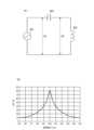
次に、図5を参照して、WPC規格で規定されているQ値計測法に基づく異物検出について説明する。図5(A)は、Q値計測法によるQuality Factor(Q-factor、品質係数、Q値)の測定方法を説明するための概略回路図である。交流電源901は、TXの送電部103が生成する交流電力を出力する電源である。送電アンテナ902は、送電アンテナ105に相当し、コンデンサ903は共振コンデンサ107に相当する。送電アンテナ902とコンデンサ903は直列に接続されている。電圧値V8は、送電部103が生成する、無線電力伝送システムを動作させるための所定周波数の電圧値である。電圧値V9は、送電アンテナ902にかかる電圧値である。ここでTXは、電圧値に関する周波数を変化させることができるものとする。また、電圧値V8およびV9は、TXがRXに対してAnalog Ping、あるいはDigital Pingを送信する際にTXが測定する電圧値である。なお、電圧値V8およびV9は交流電圧値であるので、それらの実効値(RMS)を用いてもよい。Next, referring to FIG. 5, foreign object detection based on the Q-factor measurement method defined in the WPC standard will be described. FIG. 5(A) is a schematic circuit diagram for explaining a method for measuring the Quality Factor (Q-factor, quality factor, Q-factor) by the Q-factor measurement method. The
図5(B)は周波数に対するV9/V8の測定結果の例として、100kHzにピークを有する特性を示す。横軸は周波数軸であり、縦軸は電圧比「V9/V8」を表す。V9/V8は、送電アンテナ902に係るQuality Factorを表すので、送電アンテナ902の近傍に物体が載置されると、その値は変化する。Quality Factorの変化は、TXに物体が載置されない場合と、TXにRXが載置された場合と、TXに異物(金属片等)が載置された場合と、TXにRXと異物が載置された場合とで、それぞれ異なる。 FIG. 5(B) shows a characteristic having a peak at 100 kHz as an example of measurement results of V9/V8 with respect to frequency. The horizontal axis is the frequency axis, and the vertical axis represents the voltage ratio "V9/V8". Since V9/V8 represents the Quality Factor related to the
NegotiationフェーズにてTXはRXから、FOD Status Data packetの信号を受信する。FOD Status Data packetは、Reference Quality Factor ValueおよびReference Resonance Frequency Valueを含む。Reference Quality Factor Valueは、試験用TXにRXが載置され、かつ、異物が近くに存在しない場合の、試験用TXの送電アンテナの端子で測定できるQuality Factorである。また、Reference Resonance Frequency Valueは、試験用TXにRXが載置され、かつ、異物が近くに存在しない場合の、試験用TXの送電アンテナの端子で測定できる共振周波数である。Q値計測法にて、Reference Quality Factor Valueを基準として閾値が設定される。この閾値と、実際に測定したV9/V8から求められるQuality Factorとを比較することで異物検出が行われる。あるいは、Reference Resonance Frequency Valueを基準として閾値が設定される。この閾値と、実際にV9/V8を測定して求められる共振周波数(Resonance Frequency)とを比較することで異物検出が行われる。During the Negotiation phase, the TX receives an FOD Status Data packet signal from the RX. The FOD Status Data packet includes a Reference Quality Factor Value and a Reference Resonance Frequency Value. The Reference Quality Factor Value is the Quality Factor that can be measured at the terminal of the transmitting antenna of the test TX when the RX is placed on the test TX and there is no foreign object nearby. In addition, the Reference Resonance Frequency Value is the resonant frequency that can be measured at the terminal of the power transmitting antenna of the test TX when the RX is placed on the test TX and no foreign object is present nearby. In the Q-value measurement method, a threshold is set based on the Reference Quality Factor Value. Foreign objects are detected by comparing this threshold with the Quality Factor obtained from the actually measured V9/V8. Alternatively, a threshold is set based on the Reference Resonance Frequency Value. Foreign objects are detected by comparing this threshold with the resonant frequency (Resonance Frequency) obtained by actually measuring V9/V8.
本実施形態のRXとTXは、WPC規格に基づく送受電制御のための通信を行う。WPC規格では、電力伝送が実行されるPower Transferフェーズと、実際の電力伝送前の1以上のフェーズとを含む複数のフェーズが規定されている。各フェーズにおいて必要な送受電制御のための通信が行われる。例えば、Power Loss法による異物検出は、Calibrationフェーズにより得られたデータ基に基づき、Power Transferフェーズに実施される。また、Q値計測法による異物検出は、電力伝送前(Digital Ping送信前と、NegotiationフェーズまたはRenegotiationフェーズ)に実施される。 The RX and TX of this embodiment perform communication for controlling power transmission and reception based on the WPC standard. The WPC standard defines a plurality of phases including a Power Transfer phase in which power transfer is performed and one or more phases before the actual power transfer. Communication for necessary power transmission and reception control is performed in each phase. For example, foreign object detection using the Power Loss method is performed in the Power Transfer phase based on the data base obtained in the Calibration phase. Further, foreign object detection using the Q-value measurement method is performed before power transmission (before Digital Ping transmission and during the Negotiation phase or Renegotiation phase).
WPC規格における電力伝送前のフェーズには、Selectionフェーズ、Pingフェーズ、Identification and Configurationフェーズ(Configurationフェーズ)がある。また、Negotiationフェーズ、Calibrationフェーズがある。以下では、Identification and ConfigurationフェーズをI&Cフェーズと呼ぶ。以下、各フェーズの処理について説明する。 The phases before power transmission in the WPC standard include a selection phase, a ping phase, and an identification and configuration phase. Additionally, there is a Negotiation phase and a Calibration phase. Hereinafter, the Identification and Configuration phase will be referred to as the I&C phase. The processing of each phase will be explained below.
SelectionフェーズにてTXは、Analog Pingを間欠的に送信し、物体がTXの充電台に載置されたことを検出する。例えば、充電台にRXや導体片等が載置されたことが検出される。TXは、Analog Pingを送信したときの送電アンテナ105の電圧値と電流値の一方または両方を検出する。TXは、当該電圧値が閾値を下回る場合、または当該電流値が閾値を超える場合に、物体が存在すると判断し、Pingフェーズに遷移する。あるいは、TXは、当該電圧値または当該電流値から求められるQuality Factorが所定の条件を満たす場合、物体が存在すると判断し、Pingフェーズに遷移する。 In the Selection phase, the TX intermittently transmits Analog Ping to detect that an object is placed on the charging stand of the TX. For example, it is detected that an RX, a conductor piece, etc. are placed on the charging stand. TX detects one or both of the voltage value and current value of
PingフェーズにてTXは、Analog Pingよりも電力が大きいDigital Pingを送信する。Digital Pingの電力の大きさは、TXの上に載置されたRXの制御部が起動するのに十分な電力である。RXは受電電圧値をTXへ通知する。このように、TXはDigital Pingを受信したRXからの応答を受信することにより、Selectionフェーズで検出された物体がRXであることを認識する。TXはRXから受電電圧値の通知を受けると、I&Cフェーズに遷移する。また、TXはDigital Pingの送信前に、例えばAnalog Pingを用いて、送電アンテナ105に係るQuality Factorを測定する。この測定結果は、Q値計測法を用いた異物検出処理を実行する際に使用される。なお、WPC規格のバージョンによっては、上述したSelectionフェーズが、上述したPingフェーズの一部として含まれ、Pingフェーズと呼ばれる場合もある。 In the Ping phase, the TX transmits Digital Ping, which has higher power than Analog Ping. The amount of power of Digital Ping is sufficient to activate the control unit of RX placed on top of TX. RX notifies TX of the received power voltage value. In this way, by receiving the response from the RX that has received the Digital Ping, the TX recognizes that the object detected in the Selection phase is the RX. When the TX receives notification of the power reception voltage value from the RX, it transitions to the I&C phase. Furthermore, before transmitting the Digital Ping, the TX measures the Quality Factor related to the
I&CフェーズにてTXはRXを識別し、RXから機器構成情報(能力情報)を取得する。RXは、ID Data packetおよびConfiguration Data packetの信号を送信する。ID Data packetはRXの識別子情報を含み、Configuration Data packetはRXの機器構成情報(能力情報)を含む。ID Data packetおよびConfiguration Data packetの信号を受信したTXは、アクノリッジ(肯定応答ACK)で応答する。そして、I&Cフェーズが終了する。なお、I&Cフェーズは、WPC規格のバージョンによっては、Configurationフェーズと呼ばれる場合もある。 In the I&C phase, the TX identifies the RX and acquires equipment configuration information (capability information) from the RX. RX transmits ID Data packet and Configuration Data packet signals. The ID Data packet includes RX identifier information, and the Configuration Data packet includes RX device configuration information (capability information). The TX that has received the ID Data packet and Configuration Data packet signals responds with an acknowledgement (ACK). Then, the I&C phase ends. Note that the I&C phase may be called the Configuration phase depending on the version of the WPC standard.
Negotiationフェーズでは、RXが要求するGPの値やTXの送電能力等に基づいてGPの値が決定される。またTXはRXから、上記Reference Quality Factor ValueおよびReference Resonance Frequency Valueを含むFOD Status Data packetを受信する。Q値計測法において、Reference Quality Factor ValueおよびReference Resonance Frequency Valueを基準とした閾値に基づいて、異物の有無の判定が行われる。TXは、RXからの要求に従って、Q値計測法を用いた異物検出処理を実行する。またWPC規格では、一旦Power Transferフェーズに移行した後、RXの要求によって再度Negotiationフェーズと同様の処理を行う方法が規定されている。Power Transferフェーズから移行してこれらの処理を行うフェーズのことをRenegotiationフェーズと呼ぶ。In the Negotiation phase, the GP value is determined based on the GP value requested by the RX and the power transmission capability of the TX. The TX also receives an FOD Status Data packet including the Reference Quality Factor Value and Reference Resonance Frequency Value from the RX. In the Q-value measurement method, the presence or absence of a foreign object is determined based on a threshold value based on the Reference Quality Factor Value and Reference Resonance Frequency Value. The TX performs foreign object detection processing using the Q-value measurement method in accordance with a request from the RX. The WPC standard also prescribes a method of transitioning to the Power Transfer phase, and then performing the same processing as the Negotiation phase again upon request from the RX. The phase in which this processing is performed after transitioning from the Power Transfer phase is called the Renegotiation phase.
Calibrationフェーズでは、WPC規格に基づいてPower Loss法のCAL処理が実施される。また、RXは所定の受電電力値をTXへ通知し、TXが効率よく送電するための調整を行う。所定の受電電力値とは、例えば軽負荷状態(Light Load状態)または最大負荷状態(Connected Load状態)における受電電力値である。TXへ通知された受電電力値は、Power Loss法による異物検出処理のために使用される。 In the Calibration phase, CAL processing using the Power Loss method is performed based on the WPC standard. Furthermore, the RX notifies the TX of a predetermined received power value, and makes adjustments for the TX to transmit power efficiently. The predetermined received power value is, for example, a received power value in a light load state (Light Load state) or a maximum load state (Connected Load state). The received power value notified to the TX is used for foreign object detection processing using the Power Loss method.
Power TransferフェーズではTXとRXにより、送電の開始、継続、およびエラー処理や満充電による送電停止等のための制御が行われる。TXとRXは、これらの送受電制御のための通信処理を行う。例えば、WPC規格に基づいて無線電力伝送を行う際に使用する送電アンテナ105および受電アンテナ205を用いて、送電アンテナ105または受電アンテナ205から送信される電磁波に信号を重畳して通信が行われる。なお、TXとRXとの間でWPC規格に基づく通信が可能な範囲は、TXの送電可能範囲と同様の範囲である。なお、WPC規格のバージョンによっては、上述したCalibrationフェーズも、上述したPower Transferフェーズの一部として、Power Transferフェーズと呼ばれる場合もある。In the Power Transfer phase, the TX and RX control the start and continuation of power transmission, error processing, and power transmission stop due to full charge. The TX and RX perform communication processing for these power transmission and reception control. For example, using the
次に図6を参照して、TXの制御部の機能について説明する。図6は、送電装置100(TX)の制御部101の機能構成例を示すブロック図である。制御部101は、通信制御部301、送電制御部302、測定部303、設定部304、状態検出部305を有する。通信制御部301は、第1通信部104を介してWPC規格に基づいたRXとの通信制御を行い、または、第2通信部109を介してRXとの通信制御を行う。 Next, with reference to FIG. 6, the functions of the TX control section will be explained. FIG. 6 is a block diagram showing an example of the functional configuration of the
送電制御部302は、送電部103を制御することで、RXへの送電を制御する。測定部303は、後述する波形減衰指標を測定する。また測定部303は、送電部103を介してRXに送電する電力を計測し、単位時間ごとに平均送電電力を測定する。また測定部303は、送電アンテナ105に係るQuality Factorの測定を行う。また測定部303は、送電装置100の複数個所に配置された温度センサにより温度の測定を行う。また測定部303は、送電アンテナ105と受電アンテナ205との電磁結合状態を表す量(例えば結合係数)を測定する。 The power
設定部304は、上述した方法で、Q値計測法における異物検出用の閾値や、Power Loss法における異物検出用の閾値を算出して設定する。また設定部304は、後述する方法で、波形減衰法における異物検出用の閾値を設定する。また設定部304は、例えば測定部303により測定された送電アンテナ105と受電アンテナ205との結合係数に基づき、異物検出用の閾値またはTXとRXとの位置ずれ検出用の閾値を算出して設定する。また設定部304は、例えば測定部303により測定された送電装置の温度に基づき、異物検出用の閾値またはTXとRXとの位置ずれ検出用の閾値を算出して設定する。 The
状態検出部305は、TXとRXの状態検出を行う。例えば状態検出部305は、TXとRXとの間に存在する異物の検出を行い、また、送電アンテナ105と受電アンテナ205との位置ずれを検出する。より具体的には、Power Loss法、Q値計測法、波形減衰法、送電装置100において測定された温度、送電アンテナ105と受電アンテナ205との電磁結合状態(例えば結合係数)に基づく状態検出処理が可能である。状態検出部305は、異物検出や、送電アンテナ105と受電アンテナ205との位置ずれの検出処理を、その他の方法で行うことが可能である。例えばNFC通信機能を備えるTXにおいて、状態検出部305は、NFC規格による対向機検出機能を用いて状態検出処理を行う。また、状態検出部305は、異物の有無の検出や送電アンテナと受電アンテナとの電磁結合状態の検出以外に、TX上の状態変化を検出可能である。例えば状態検出部305は、TX上の受電装置200の数の増減を検出可能である。 The
設定部304は、TXが状態検出を行う上で、異物の有無を判定するための基準となる閾値を設定する。状態検出とは、例えばPower Loss法、Q値計測法、波形減衰法に基づく状態検出、送電装置100において測定された温度に基づく状態検出、または送電アンテナ105と受電アンテナ205との結合係数等に基づく状態検出である。なお、設定部304は、その他の方法を用いた状態検出処理に必要となる判定用閾値を設定することができる。状態検出部305は、設定部304により設定された閾値と、測定部303による測定結果に基づいて、異物検出処理や送電アンテナ105と受電アンテナ205との位置ずれの検出処理を行うことができる。例えば状態検出部305は、測定部303の測定結果として、波形減衰指標、送電電力、Quality Factor、送電装置100において測定された温度、送電アンテナ105と受電アンテナ205との結合係数等のデータを取得可能である。The
図6に示す通信制御部301、送電制御部302、測定部303、設定部304、状態検出部305が実行する処理については、制御部101の備えるCPU等が実行するプログラムを用いて実現可能である。各処理は、それぞれが独立したプログラムにしたがい、イベント処理等によりプログラム間の同期をとりながら並行して実行される。ただし、これらの処理のうち、2つ以上が1つのプログラムによる処理に組み込まれていてもよい。 The processes executed by the
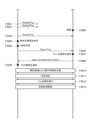
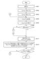
続いて、TXおよびRXが実行する送受電制御に係る処理の流れの例を説明する。図7は、TXが実行する送電制御処理例を示すフローチャートである。本処理は、例えばTXの制御部101がメモリ106から読み出したプログラムを実行することによって、実現される。また、本処理は、TXの電源がオンされたことに応じて、TXのユーザが無線電力伝送アプリケーションの開始指示を入力したことに応じて、または、TXが商用電源に接続され電力供給を受けていることに応じて、実行されうる。また、他の契機によって本処理が開始されてもよい。 Next, an example of the flow of processing related to power transmission and reception control executed by TX and RX will be described. FIG. 7 is a flowchart illustrating an example of power transmission control processing executed by the TX. This process is realized, for example, by the
図7のS1201でTXは、WPC規格のSelectionフェーズとPingフェーズとして規定されている処理を実行し、RXが載置されるのを待ち受ける。TXは、WPC規格のAnalog Pingを繰り返し間欠送信し、送電可能範囲内に存在する物体を検出する。例えばTXは、充電台300にRXや導体片等が載置されたことを検出可能である。TXは送電可能範囲内に物体が存在することを検出した場合、Digital Pingを送信する。Digital Pingの電力は、Analog Pingの電力より大きく、TXの上に載置されたRXの制御部201が起動するのに十分な電力である。 In S1201 of FIG. 7, the TX executes processing defined as the Selection phase and Ping phase of the WPC standard, and waits for the RX to be placed. The TX repeatedly and intermittently transmits Analog Ping according to the WPC standard, and detects objects existing within the range where power can be transmitted. For example, the TX can detect that an RX, a conductor piece, or the like is placed on the charging
TXは、Digital Pingに対する所定の応答があった場合、検出された物体がRXであり、RXが充電台300に載置されたと判定する。ここで、「所定の応答」とは、RXが送信する、Singnal Strength (SIG) data Packetである。このパケットは、RXが受信する信号の信号強度を表すSingnal Strength Valueを含む。Singnal Strength Valueは、RXが測定する受電部203の整流部(整流器)が出力する電圧(整流部出力電圧)、またはRXが測定する受電アンテナ205を含む開回路の電圧(開回路電圧)から算出される。またはSingnal Strength Valueは、RXが測定する受電電力値等から算出される。When there is a predetermined response to the Digital Ping, the TX determines that the detected object is the RX and that the RX has been placed on the charging
また、TXはDigital Pingの送信前に、送電アンテナ105のQuality Factorの測定を行う。この測定結果は、Q値測定法を用いた異物検出処理を実行する際に使用される。 Furthermore, the TX measures the Quality Factor of the
RXの載置が検出された後、S1202でTXは、WPC規格で規定されたI&Cフェーズの通信により、そのRXから識別情報を取得する。I&CフェーズにてRXは、Identification Packet(ID Packet)をTXへ送信する。ID Packetには、RXの個体ごとの識別情報であるManufacturer CodeとBasic Device IDの他に、対応しているWPC規格のバージョンを特定可能な情報要素が格納される。 After the placement of the RX is detected, in step S1202, the TX acquires identification information from the RX through I&C phase communication defined in the WPC standard. In the I&C phase, RX transmits an Identification Packet (ID Packet) to TX. In addition to the Manufacturer Code and Basic Device ID, which are identification information for each individual RX, the ID Packet stores information elements that can identify the version of the supported WPC standard.
さらに、RXは、Configuration Data PacketをTXへ送信する。Configuration Data Packetには、以下に示すRXの能力情報が含まれる。
・RXが対応しているWPC規格のバージョンを特定することが可能な情報。
・RXが負荷に供給できる最大電力を特定する値であるMaximum Power ValueあるいはReference Power。
・RXがWPC規格のNegotiation機能を有するか否かを示す情報。
・TXがRXに対して情報を送信する際に用いる通信の変調方式である周波数偏移変調において使用されるパラメータ。 Furthermore, the RX transmits a Configuration Data Packet to the TX. The Configuration Data Packet includes the following RX capability information:
- Information that makes it possible to identify the version of the WPC standard that the RX supports.
- Maximum Power Value or Reference Power, which is a value that specifies the maximum power the RX can supply to the load.
Information indicating whether the RX has a WPC standard Negotiation function.
A parameter used in frequency shift keying, which is a communication modulation method used when TX transmits information to RX.
TXは、上記パケットをRXから受信すると、肯定応答ACKをRXに送信し、I&Cフェーズが終了する。なお、TXは、WPC規格のI&Cフェーズの通信以外の方法でRXの識別情報を取得してもよい。また、RXの個体ごとの識別情報は、Wireless Power IDでもよい。あるいは、RXの第2通信部212に固有のBluetooth Address(以下、「BD_ADDR」と記す)等の、RXの個体を識別可能な任意の他の識別情報であってもよい。なお、BD_ADDRは、BLEで使用する8バイトのアドレスである。BD_ADDRは、例えば、RXの製造メーカや、BLEの通信機能(第2通信部212)の個体識別情報を示す、BLE規格で規定されたPublic Addressである。BD_ADDRは、Random Addressであってもよい。 When the TX receives the packet from the RX, it sends an acknowledgment ACK to the RX and the I&C phase ends. Note that the TX may acquire the identification information of the RX by a method other than communication in the I&C phase of the WPC standard. Further, the identification information for each individual RX may be a Wireless Power ID. Alternatively, it may be any other identification information that can identify the individual RX, such as a Bluetooth Address (hereinafter referred to as "BD_ADDR") specific to the
続いてS1203でTXは、RXからの要求と自装置の送電能力に基づいて、そのRXとの交渉によってGPを決定する。S1203では、WPC規格のNegotiationフェーズの通信が行われる。まず、RXは、TXに対してSpecific Requestを送信することで、要求するGPの値を通知する。TXは、自装置の送電能力やその他の条件に基づいて、要求を受け入れるか否かを判定する。TXは要求を受け入れる場合に肯定応答ACKをRXへ送信し、要求を受け入れない場合には否定応答であるNACKまたはNAKをRXへ送信する。決定されるGPの値は、TXがRXからの要求を受け入れた場合にRXが要求した値となる。TXがRXからの要求を受け入れない場合には、WPC規格で定められた所定の値(例えば5ワット)となる。あるいはTXは、RXがNegotiationフェーズに対応していないことを示す情報を取得した場合(例えば後述のS1302)、Negotiationフェーズの通信を行わず、GP値を所定値に決定する。所定値とは、例えばWPC規格で予め規定された値(例えば5ワット)である。Next, in S1203, the TX determines the GP by negotiation with the RX based on the request from the RX and the power transmission capacity of the device itself. In S1203, communication in the negotiation phase of the WPC standard is performed. First, the RX notifies the TX of the requested GP value by sending a Specific Request to the TX. The TX determines whether to accept the request based on the power transmission capacity of the device itself and other conditions. If the TX accepts the request, it sends a positive response ACK to the RX, and if the TX does not accept the request, it sends a negative response NACK or NAK to the RX. The determined GP value is the value requested by the RX when the TX accepts the request from the RX. If the TX does not accept the request from the RX, the value is a predetermined value (e.g., 5 watts) defined in the WPC standard. Alternatively, if the TX acquires information indicating that the RX does not support the negotiation phase (e.g., S1302 described below), it does not perform communication in the negotiation phase and sets the GP value to a predetermined value. The predetermined value is, for example, a value (e.g., 5 watts) that is predefined in the WPC standard.
またTXは、RXからの要求に従って、Q値測定法を用いた異物検出処理を実行する。TXはRXから、FOD Status Data packetを受信する。このパケットは上述したReference Quality Factor ValueおよびReference Resonance Frequency Valueを含む。そして、TXはQ値測定法による異物検出を実行する。この異物検出は、以下の情報に基づいて行われる。
・TXがDigital Pingの送信前に測定した、送電アンテナ105のQuality Factorおよび共振周波数。
・TXがRXから受信したReference Quality Factor ValueおよびReference Resonance Frequency Valueを基準とする閾値。 Furthermore, the TX executes foreign object detection processing using the Q value measurement method in accordance with a request from the RX. TX receives the FOD Status Data packet from RX. This packet includes the above-mentioned Reference Quality Factor Value and Reference Resonance Frequency Value. The TX then performs foreign object detection using the Q value measurement method. This foreign object detection is performed based on the following information.
- Quality Factor and resonance frequency of the
- A threshold value based on the Reference Quality Factor Value and Reference Resonance Frequency Value that the TX receives from the RX.
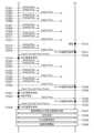
続いてS1204でTXとRXは、WPC規格のCalibrationフェーズの処理(CAL処理)を行う。TXは、Calibrationフェーズにおいて、決定したReference Powerの値またはGPの値に基づいてPower Loss法のCAL処理を実行する。まず、RXは、TXに対し、軽負荷状態における受電電力に関する情報(以下、第1の基準受電電力情報という)を有する信号を送信する。軽負荷状態は、例えば負荷切断状態や、RXの受電電力値が第1の閾値以下になる負荷状態、あるいはRXの受電電力値が予め定められた所定範囲(以下、「第1の範囲」という)内になる負荷状態である。本実施形態では、第1の基準受電電力情報は、500ミリワットであるとする。第1の基準受電電力情報は、WPC規格で規定されるReceived Power Data packet(mode1)に含まれる情報であるが、他のメッセージが用いられてもよい。以下、Received Power Data packet(mode1)をRP1と表記する。TXは、RXから受信するControl Error(CE) data Packetの中に含まれる、Control Error Valueに基づいて、第1の基準受電電力情報を受け入れるか否かを判定する。TXは第1の基準受電電力情報を受け入れる場合、肯定応答ACKをRXへ送信する。また、TXは第1の基準受電電力情報を受け入れない場合、否定応答NAKをRXへ送信する。 Next, in S1204, the TX and RX perform calibration phase processing (CAL processing) according to the WPC standard. In the Calibration phase, the TX executes CAL processing using the Power Loss method based on the determined Reference Power value or GP value. First, the RX transmits a signal having information regarding received power in a light load state (hereinafter referred to as first reference received power information) to the TX. The light load state is, for example, a load disconnection state, a load state in which the received power value of the RX is equal to or less than a first threshold value, or a state in which the received power value of the RX is within a predetermined range (hereinafter referred to as the "first range"). ) is the load state. In this embodiment, it is assumed that the first reference received power information is 500 milliwatts. The first reference received power information is information included in the Received Power Data packet (mode 1) defined by the WPC standard, but other messages may be used. Hereinafter, the received power data packet (mode 1) will be referred to as RP1. The TX determines whether to accept the first reference received power information based on the Control Error Value included in the Control Error (CE) data packet received from the RX. If the TX accepts the first reference received power information, it sends an acknowledgment ACK to the RX. Furthermore, if the TX does not accept the first reference received power information, it transmits a negative response NAK to the RX.
次に、RXは、TXに対し、負荷接続状態における受電電力に関する情報(以下、第2の基準受電電力情報という)を有する信号を送信するための処理を行う。負荷接続状態は、例えば最大負荷状態や、送電電力値が第2の閾値以上になる負荷状態、あるいは、RXが受電する電力が最大の電力となる負荷状態である。ここで、「最大の電力」とは、Reference Powerに近い値の電力である。あるいは負荷接続状態は、RXの受電電力値が予め定められた所定範囲(以下、「第2の範囲」という)内になる負荷状態である。ここで、第2の範囲は第1の範囲よりも高い電力値の範囲である。本実施形態では、第2の基準受電電力情報を15ワットとする。第2の基準受電電力情報は、WPC規格で規定されるReceived Power Data packet(mode2)に含まれる情報であるが、他のメッセージが用いられてもよい。以下、Received Power Data packet(mode2)をRP2と表記する。TXは、RXから受信するControl Error(CE) data Packetの中に含まれる、Control Error Valueに基づいて、第2の基準受電電力情報を受け入れるか否かを判定する。TXは第2の基準受電電力情報を受け入れる場合、肯定応答ACKをRXへ送信する。また、TXは第2の基準受電電力情報を受け入れない場合、否定応答NAKをRXへ送信する。TXは、RXからの第2の基準受電電力情報に対して肯定応答ACKを送信し、CAL処理を完了する。 Next, the RX performs processing for transmitting a signal having information regarding the received power in the load connected state (hereinafter referred to as second reference received power information) to the TX. The load connection state is, for example, a maximum load state, a load state in which the transmitted power value is equal to or greater than a second threshold value, or a load state in which the power received by the RX is the maximum power. Here, the "maximum power" is a power close to the Reference Power. Alternatively, the load connection state is a load state in which the received power value of the RX falls within a predetermined range (hereinafter referred to as "second range"). Here, the second range is a range of power values higher than the first range. In this embodiment, the second reference received power information is 15 watts. The second reference received power information is information included in the Received Power Data packet (mode 2) defined by the WPC standard, but other messages may be used. Hereinafter, the received power data packet (mode 2) will be referred to as RP2. The TX determines whether to accept the second reference received power information based on the Control Error Value included in the Control Error (CE) data packet received from the RX. If the TX accepts the second reference received power information, it sends an acknowledgment ACK to the RX. Furthermore, when the TX does not accept the second reference received power information, it transmits a negative response NAK to the RX. The TX sends an acknowledgment ACK to the second reference received power information from the RX and completes the CAL process.
以上のCAL処理により、TXは、TXの送電電力値、および、第1および第2の基準受電電力情報に含まれる受電電力値に基づいて、軽負荷状態と負荷接続状態におけるTXとRXとの間の電力損失量を算出することが可能となる。またTXは、複数の電力損失量の間の補間処理を行うことで、TXが取り得るすべての送電電力におけるTXとRXとの間の電力損失量を算出することができる。TXが取り得るすべての送電電力とは、例えば本実施形態にてRXが受電する受電電力が500ミリワットから15ワットになる範囲における、任意の電力である。 Through the above CAL processing, the TX can adjust the TX and RX in the light load state and the load connected state based on the TX transmitted power value and the received power value included in the first and second reference received power information. It becomes possible to calculate the amount of power loss between Furthermore, by performing interpolation processing between a plurality of power loss amounts, the TX can calculate the power loss amounts between the TX and RX in all the transmitted power that the TX can take. All the transmitted power that the TX can take is, for example, any power in the range in which the received power received by the RX in this embodiment is from 500 milliwatts to 15 watts.
その後、S1205でTXは、RXのバッテリ207が満充電となるまで送電を行う。S1205では、WPC規格のPower Transferフェーズの通信が行われる。RXは、TXに対してt_intervalの時間間隔で繰り返しControl Error(CE) data Packet(以下、「CEパケット」という)を送信する。t_intervalはWPC規格で定義される値であり、例えば250ミリ秒である。CEパケットには、送電電力をどのくらい上げ下げするかの要求が含まれる。TXは、受信したCEパケットに基づいて送電アンテナ105の電流または電圧を制御することで送電電力を調整する。つまり、CEパケットは、送電電力を調整するためのパラメータのデータを含む。この処理を繰り返すことで、RXの要求に応じた適切な電力での送電がほぼリアルタイムに行われる。After that, in S1205, the TX transmits power until the
RXは、バッテリ207が満充電となるとEnd Power Transfer data Packet(以下、「EPTパケット」という)を送信して、Power Transferフェーズを終了させる。RXは、満充電以外の理由でEPTパケットを送信することが可能である。また、TXはPower Transferフェーズが終了すると、RXに対する充電のための送電を停止する。When the
またTXは、最後にCEパケットを受信してからt_timeoutの時間が経過した後で、次のCEパケットが受信できなかった場合、RXが充電台300から取り去られたと判断する。この場合、Power Transferフェーズを終了する。t_timeoutはWPC規格で定義される値であり、例えば1500ミリ秒である。 Furthermore, if the next CE packet cannot be received after the time t_timeout has elapsed since the last CE packet was received, the TX determines that the RX has been removed from the charging
RXはPower Transferフェーズ中にCEパケット以外のパケットをTXに送信してもよい。例えば、RXのバッテリ207の状態をTXに通知するCharge Status Data Packetがある。このパケットには、バッテリ207が何パーセント充電されたかを表すCharge Status Valueが格納される。TXは、Charge Status Data Packetを受信すると、例えばUI部110により、Charge Status Valueに基づいて文字や図で表示を行うことでユーザに充電状態を通知する。Charge Status Data Packetに関してTXは、いつ受信してもよいし、任意のタイミングでユーザへの通知を行ってもよい。 The RX may send packets other than CE packets to the TX during the Power Transfer phase. For example, there is a Charge Status Data Packet that notifies the TX of the state of the
Power TransferフェーズにてTXはRXへの送電を行うとともに、Power Loss法による異物検出処理を行う。例えばCAL処理により、送電電力値と受電電力値との差分から、送電処理中の第1の検出状態におけるTXとRXとの間の電力損失量が算出される。算出された電力損失量は、異物が存在しない状態における、基準の電力損失量に相当する。そしてTXは、CAL処理後の送電中に測定された、TXとRXとの間の電力損失量と、基準の電力損失量との差分が閾値以上であると判定した場合、第2の検出状態と判断する。In the Power Transfer phase, the TX transmits power to the RX and performs foreign object detection processing using the Power Loss method. For example, the amount of power loss between the TX and RX in the first detection state during power transmission processing is calculated from the difference between the transmitted power value and the received power value by CAL processing. The calculated amount of power loss corresponds to a reference amount of power loss in a state in which no foreign object is present. Then, when the TX determines that the difference between the amount of power loss between the TX and RX measured during power transmission after CAL processing and the reference amount of power loss is equal to or greater than a threshold value, it determines that the second detection state is present.
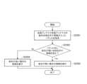
図8を参照して、RXが実行する受電制御に係る処理の流れの例を説明する。本処理は、例えばRXの制御部201がメモリ208から読み出したプログラムを実行することによって実現される。S1301でRXは、WPC規格のSelectionフェーズとPingフェーズとして規定される処理を実行し、自装置がTXに載置されるのを待つ。RXは、例えば、TXからのDigital Pingを検出することによって、TXに載置されたことを検出する。An example of the flow of processing related to power reception control executed by the RX will be described with reference to FIG. 8. This processing is realized, for example, by the
RXは自装置がTXに載置されたことを検知すると、S1302にてID PacketとConfiguration Data Packetにより、自装置の識別情報を含む信号をTXへ送信する。なお、RXの識別情報は、WPC規格のI&Cフェーズの通信以外の方法で送信されてもよい。また、RXの各個体を識別可能な情報であれば、BD_ADDR等の他の識別情報が用いられてもよい。また、RXは、S1302において、識別情報以外の情報をTXへ送信することが可能である。When the RX detects that its own device has been placed on the TX, in S1302 it transmits a signal including its own device's identification information to the TX using an ID Packet and a Configuration Data Packet. Note that the RX's identification information may be transmitted by a method other than communication in the I&C phase of the WPC standard. Also, other identification information such as BD_ADDR may be used as long as it is information that can identify each individual RX. Also, in S1302, the RX can transmit information other than the identification information to the TX.
続いてS1303でRXは、TXに対して要求するGP値の情報を含む信号を送信し、TXからの応答を待ってGPを決定する。S1303では、WPC規格のNegotiationフェーズの通信が行われる。RXは、TXに対してFOD Status Data packetを送信する。このパケットは、Reference Quality Factor ValueおよびReference Resonance Frequency Valueを含む。 Next, in S1303, the RX transmits a signal including information on the requested GP value to the TX, waits for a response from the TX, and determines the GP. In S1303, communication in the negotiation phase of the WPC standard is performed. RX transmits a FOD Status Data packet to TX. This packet includes Reference Quality Factor Value and Reference Resonance Frequency Value.
続いてS1304でRXとTXは、WPC規格のCalibrationフェーズの処理(CAL処理)を行う。当該フェーズでRXが実施する処理については上述の通りである。その後、S1305でRXは、バッテリ207が満充電となるまで受電する。当該フェーズでRXが実施する処理については上述の通りである。Power TransferフェーズにてRXとTXは、Power Loss法による異物検出処理を行う。S1305では、RXはt_intervalの間隔でCEパケットを繰り返し送信し、最後にEPTパケットをTXに送信して処理を終了する。Next, in S1304, the RX and TX perform processing of the Calibration phase of the WPC standard (CAL processing). The processing performed by the RX in this phase is as described above. After that, in S1305, the RX receives power until the
以上のように、Power Loss法は、TXからRXへの送電中に、電力損失量の測定結果に基づいて異物検出を行う方法である。この方法は、TXが大きな電力を送電しているときに異物検出の精度が低下するという短所がある反面で、送電を継続しつつ異物検出処理を行えるので、高い送電効率を保つことができるという長所がある。 As described above, the Power Loss method is a method of detecting foreign objects based on the measurement results of the amount of power loss during power transmission from TX to RX. Although this method has the disadvantage that the accuracy of foreign object detection decreases when the TX is transmitting large amounts of power, it is possible to maintain high power transmission efficiency because foreign object detection processing can be performed while power transmission continues. There are advantages.
ところで、Power Transferフェーズ中における、Power Loss法による異物検出のみでは、異物の誤検出が発生する可能性や、異物が存在するにも関わらず異物なしと判定される誤判定が発生する可能性がある。例えば、Power Transferフェーズでの送電中に、TXとRXの近傍に異物が存在する場合を想定する。この場合、異物からの発熱等が大きくなる可能性があるので、Power Transferフェーズにおける異物検出精度の向上が求められる。そこで、波形減衰法を用いた異物検出方法について説明する。この方法では、TXはRXに対して行う送電に係る送電波形(電圧波形または電流波形)の減衰状態に基づいて異物検出を行うことが可能である。すなわち新たに規定される異物検出用信号等を用いることなく、異物検出が可能となる。 By the way, if only the Power Loss method is used to detect foreign objects during the Power Transfer phase, there is a possibility that erroneous detection of foreign objects will occur, or there will be a possibility that there will be an erroneous determination that there is no foreign object even though there is a foreign object. be. For example, assume that a foreign object exists near TX and RX during power transmission in the Power Transfer phase. In this case, there is a possibility that heat generation from the foreign object will increase, so it is required to improve the accuracy of foreign object detection in the Power Transfer phase. Therefore, a foreign object detection method using the waveform attenuation method will be explained. In this method, the TX can detect foreign objects based on the attenuation state of the power transmission waveform (voltage waveform or current waveform) related to the power transmission performed to the RX. In other words, foreign matter can be detected without using a newly defined foreign matter detection signal or the like.
図9は、波形減衰法による異物検出原理を説明する図である。送電装置100(TX)から受電装置200(RX)への送電に係る送電波形を用いた異物検出の例を示す。図9にて横軸は時間軸であり、縦軸は電圧値または電流値を表す。図9に示す波形600は、例えばTXの送電アンテナ105に印加される高周波電圧の電圧値の時間経過に伴う変化を示している。送電アンテナ105を介してRXに送電を行っているTXは、時刻T0において送電を停止する。時刻T0では、電源部102からの送電用の電力供給が停止され、送電アンテナ105への送電用の電力供給が停止される。時刻T0において送電を停止するよりも前の送電波形の周波数f1は、例えばWPC規格で使用される87kHzから205kHzまでの間にある、固定された周波数である。波形600上の点601は、高周波電圧の包絡線上の点であり、時刻T1における電圧値A1に対応する。点601にて(T1,A1)は、時刻T1における電圧値がA1であることを示す。波形600上の点602は、高周波電圧の包絡線上の点であり、時刻T2における電圧値A2に対応する。点602にて(T2、A2)は、時刻T2における電圧値がA2であることを示す。 FIG. 9 is a diagram for explaining the principle of foreign object detection by the waveform attenuation method. An example of foreign object detection using a transmission waveform related to power transmission from a power transmitting device 100 (TX) to a power receiving device 200 (RX) is shown. In FIG. 9, the horizontal axis is the time axis, and the vertical axis is the voltage value or current value. A
送電アンテナ105の品質係数を表すQuality Factor(Q-factor、Q値)は、時刻T0以降の電圧値の時間変化に基づいて求めることが可能である。例えば、高周波電圧の包絡線上の点601および602における時刻、電圧値、および時刻T0において送電を停止した後の高周波電圧の周波数f2に基づいて、TXは式1によりQuality Factorを算出する。
Q=π・f2・(T2-T1)/ln(A1/A2) (式1)
式1中、lnは自然対数関数を表す。なお、TXがRXに送電している時の送電波形の周波数(f1)と、TXがRXへの送電を停止した時の送電波形の周波数(f2)は異なる場合がある。 A Quality Factor (Q-factor, Q value) representing the quality factor of the
Q = π f2 (T2 - T1 ) / ln (A1 / A2 ) (Equation 1)
In Equation 1, ln represents a natural logarithm function. Note that the frequency (f1 ) of the transmission wave when the TX is transmitting power to the RX may differ from the frequency (f2 ) of the transmission wave when the TX stops transmitting power to the RX.
Quality Factorの値は、TXとRXの近傍に異物が存在する場合に低下するが、その理由は異物によってエネルギー損失が発生するからである。よって、電圧値の減衰の傾きに着目すると、異物が存在しない場合よりも、異物が存在する場合の方が、点601と点602を結ぶ直線の傾きは大きくなる。異物によるエネルギー損失が発生する場合、波形600の振幅の減衰率が高くなる。例えば波形減衰法では、点601と点602との間の電圧値の減衰状態に基づいて異物の有無の判定を行うことができる。実際に異物の有無を判定する上では、減衰状態を表す何らかの数値の比較によって判定をすることが可能となる。例えば、Quality Factorを用いて判定を行う場合、Quality Factorの値が基準値よりも低くなることは、波形減衰率(単位時間当たりの波形の振幅の減少度合い)が高くなることを意味する。The value of the Quality Factor decreases when a foreign object is present near TX and RX, because the foreign object causes energy loss. Therefore, when focusing on the slope of the attenuation of the voltage value, the slope of the
別例として、(A1-A2)/(T2-T1)により算出される、点601と点602を結ぶ直線の傾きを用いて判定を行う方法がある。また、電圧値の減衰状態を測定する時刻(T1およびT2)が固定であるとした場合、電圧値の差(A1-A2)や、電圧値の比(A1/A2)を用いて、異物の有無の判定を行うことができる。あるいは、送電を停止した直後の電圧値A1が一定であるとした場合、所定の時間経過後の電圧値A2を用いて、異物の有無の判定を行うことができる。あるいは、電圧値A1が所定の電圧値A2となるまでの経過時間(T2-T1)を用いて、異物の有無の判定を行うことができる。 As another example, there is a method of making a judgment using the slope of the
波形減衰法では、送電停止期間中の波形の減衰状態によって異物の有無を判定することが可能である。減衰状態を表すQuality Factor等の指標を、本実施形態では「波形減衰指標」と総称する。また図9の縦軸を、TXの送電アンテナ105に印加される高周波電圧の電圧値の軸として説明したが、図9の縦軸を、送電アンテナ105を流れる電流値としてもよい。電圧値の場合と同様に、送電停止期間中の電流値の減衰状態が異物の有無によって変化する。異物が存在する場合には、異物が存在しない場合よりも波形減衰率が高くなる。よって、送電アンテナ105を流れる電流値の時間変化に関して、上述と同様の方法を適用して異物を検出することができる。すなわち、電流波形より算出されるQuality Factor、電流値の減衰の傾き、電流値の差、電流値の比、電流値の絶対値、または電流値が所定値になるまでの時間等を波形減衰指標として用いて異物の有無を判定し、異物検出を行うことができる。In the waveform attenuation method, the presence or absence of a foreign object can be determined based on the attenuation state of the waveform during the power transmission stop period. Indicators such as the Quality Factor that indicate the attenuation state are collectively referred to as "waveform attenuation indexes" in this embodiment. In addition, the vertical axis of FIG. 9 has been described as the axis of the voltage value of the high-frequency voltage applied to the TX
また、電圧値の減衰状態と電流値の減衰状態の両方に基づく方法がある。この方法では、電圧値の波形減衰指標と電流値の波形減衰指標とから算出される評価値を用いて異物の有無を判定することができる。なお、TXが送電を一時停止した期間の波形減衰指標を測定する例に限定されることはない。TXが電源部102から供給される電力を所定の電力レベルからそれより低い電力レベルまで一時的に下げた期間の波形減衰指標を測定してもよい。つまり、送電アンテナ105への送電用の電力供給を所定の電力レベルからそれより低い電力レベルまで一時的に下げた期間の波形減衰指標を測定してもよい。また、上述した送電アンテナ105への送電用の電力供給の制限あるいは停止は、制御部101の指示信号に基づいて送電部103が行ってもよい。また、上述の例では、TXが送電を制限する期間における2つの時点での電圧値または電流値が測定される構成としたが、3つ以上の時点での電圧値または電流値の測定を行ってもよい。 There is also a method based on both the attenuation state of the voltage value and the attenuation state of the current value. In this method, the presence or absence of a foreign object can be determined using the evaluation value calculated from the waveform attenuation index of the voltage value and the waveform attenuation index of the current value. Note that the present invention is not limited to the example in which the waveform attenuation index is measured during the period in which the TX temporarily suspends power transmission. The waveform attenuation index may be measured during a period in which the power supplied from the
図10を参照して、波形減衰法による送電波形に基づく異物検出方法について説明する。図10に示す送電波形は、波形減衰法による異物検出を行う際の送電波形であり、横軸は時間を表し、縦軸は送電アンテナ105の電圧値または電流値を表す。With reference to Figure 10, a foreign object detection method based on a transmission waveform using the waveform attenuation method will be described. The transmission waveform shown in Figure 10 is a transmission waveform when detecting a foreign object using the waveform attenuation method, with the horizontal axis representing time and the vertical axis representing the voltage value or current value of the
TXが送電を開始した直後の過渡応答期間には、送電波形が安定しない。よって、この過渡応答期間中にRXは、TXに対して通信(振幅変調または負荷変調による通信)を行わないように制御する。また、TXはRXに対して通信(周波数偏移変調による通信)を行わないように制御する。以降、この期間を通信禁止期間と呼ぶ。ただし、通信禁止期間中、TXはRXに対して送電を行う。そして通信禁止期間の経過後にTXはRXに対して送電を行う。以降、この期間を送電期間と呼ぶ。TXは、RXから異物検出実行要求(パケット、コマンド)を受信した場合、所定期間の経過後に送電を一時停止するか、または送電電力を一時的に低下させる。以降、この所定期間を準備期間と呼ぶ。During the transient response period immediately after the TX starts transmitting power, the transmission waveform is not stable. Therefore, during this transient response period, the RX controls the TX so that it does not communicate with the TX (communication by amplitude modulation or load modulation). The TX also controls the RX so that it does not communicate with the RX (communication by frequency shift keying). Hereinafter, this period is called the communication prohibited period. However, during the communication prohibited period, the TX transmits power to the RX. Then, after the communication prohibited period has elapsed, the TX transmits power to the RX. Hereinafter, this period is called the power transmission period. When the TX receives a request (packet, command) to execute foreign object detection from the RX, the TX suspends power transmission after a specified period has elapsed, or temporarily reduces the transmission power. Hereinafter, this specified period is called the preparation period.
上記異物検出実行要求(パケット、コマンド)はRP0、RP1、またはRP2であってもよい。異物検出実行要求を受信したTXの送電部103は、送電を一時停止するか、または送電電力が一時的に低下するので、送電波形の振幅は減衰する。送電を一時停止させる時点、または送電電力を一時的に低下させる時点から、送電の再開時点、または送電電力の復帰を開始する時点までの期間を、送電電力制御期間と呼ぶ。TXは減衰波形に基づく波形減衰指標を算出し、算出した波形減衰指標と所定の閾値を比較することにより、異物の有無、あるいは異物が存在する可能性(存在確率)を判定(以下、異物判定ともいう)する。異物判定は、送電電力制御期間中、通信禁止期間、または送電期間に実施することができる。The foreign object detection execution request (packet, command) may be RP0, RP1, or RP2. The
送電電力制御期間の経過後、異物が検出されない場合にTXは送電の再開または送電電力の復帰の制御を行う。当該制御が開始された直後の過渡応答期間には、送電波形が安定しないので、当該期間は通信禁止期間となる。その後、TXからRXに対して安定して送電を行う送電期間に移行する。If no foreign object is detected after the transmission power control period has elapsed, the TX will resume transmission or control the return of transmission power. During the transient response period immediately after this control begins, the transmission waveform is not stable, so this period becomes a communication prohibited period. After that, the TX transitions to a power transmission period in which stable power transmission is performed from the TX to the RX.
以上のように、TXは、送電開始、通信禁止期間、送電期間、準備期間、送電電力制御期間の制御を繰り返し行う。TXは、所定のタイミングで減衰波形に基づく波形減衰指標を算出し、算出した波形減衰指標と所定の閾値との比較結果から異物判定を行う。つまり、送電が制限(送電停止を含む)される所定期間にて2以上の時点における電圧値または電流値に基づいて異物判定を行うことができる。 As described above, the TX repeatedly controls the start of power transmission, the communication prohibition period, the power transmission period, the preparation period, and the transmission power control period. The TX calculates a waveform attenuation index based on the attenuation waveform at a predetermined timing, and performs foreign object determination based on a comparison result between the calculated waveform attenuation index and a predetermined threshold. In other words, foreign object determination can be performed based on voltage values or current values at two or more points in time during a predetermined period in which power transmission is restricted (including power transmission stoppage).
ところで、送電電力制御期間にて、受電装置200の受電アンテナ205と共振コンデンサ211に、受電部203、充電部206、およびバッテリ207等の要素が接続されていると、波形減衰指標は、これらの要素による負荷の影響を受ける。すなわち、受電部203、充電部206、およびバッテリ207の状態によって、波形減衰指標の値が変化することになる。その結果、例えば波形減衰指標の値が大きい場合でも、それが異物による影響であるのか、あるいは受電部203、充電部206、バッテリ207等の状態変化によるのかを区別することが困難になる。そこで、波形減衰指標を測定して異物検出を行う場合、RXの制御部201は準備期間中に第1スイッチ部209をOFFにする。これにより、バッテリ207による影響を抑制することが可能である。また、第1スイッチ部209を切断した状態の代わりに、Light Load状態(軽負荷状態)とすることによっても同様の効果が得られる。また、第1スイッチ部209を切断した状態の代わりに、RXは受電する電力が最小の電力となるように負荷制御を行うことによっても同様の効果が得られる。あるいは、第1スイッチ部209を切断した状態の代わりに、RXは受電する電力が予め定められた所定の範囲内の電力、または、所定の閾値以下の電力となるように負荷制御を行うことによっても同様の効果が得られる。ここで、「予め定められた所定の範囲内の電力」または「所定の閾値以下の電力」において、「電力」とは、Reference Powerのおよそ10%の値の電力である。あるいは、第1スイッチ部209を切断した状態の代わりに、RXは所定の電力が負荷に供給されるように、負荷を制御してもよい。これらは、第1スイッチ部209を制御することによって実現できる。あるいは、制御部201は第2スイッチ部210をONにして短絡し、受電アンテナ205、共振コンデンサ211、および第2スイッチ部210で形成される閉ループに電流が流れる状態とする。これにより、受電部203、充電部206、およびバッテリ207の影響を抑制することが可能になる。RXはTXに対して異物検出実行要求(コマンド)を送信し、準備期間に上記処理が実施される。第1スイッチ部209を切断した状態、または第2スイッチ部210をONにして短絡(接続)した状態で測定される送電波形に基づく波形減衰指標を取得することで、より精度の高い異物検出が可能となる。あるいは、第1スイッチ部209の切断、および第2スイッチ部210の短絡(接続)の両方を実施することで、さらに精度の高い異物検出が可能である。 By the way, if elements such as the
あるいは、RXは準備期間中に、第1スイッチ部209をONにして短絡し、第2スイッチ部210をOFFにして切断した状態において、低消費電力モードに移行させるか、または消費電力が一定になるように制御を行ってもよい。RXでの消費電力が一定でない場合や、大きな電力が消費される場合には、減衰波形に基づく波形減衰指標の値が消費電力の変動の影響を受ける。当該影響を抑制するために、RXで動作するソフトウェアアプリケーションの動作の制限もしくは停止、または、RXが有するハードウェア機能ブロックを低消費電力モードもしくは動作停止モードの設定が有効である。RXの消費電力を抑制した状態で測定される送電波形に基づく波形減衰指標を用いて異物検出を行うことで、より精度の高い異物検出が可能となる。Alternatively, during the preparation period, the RX may be controlled to enter a low power consumption mode or to maintain constant power consumption with the
またTXにおいても同様に、波形減衰指標の測定時に、送電装置100の送電アンテナ105と共振コンデンサ107に、送電部103、第1通信部104、および電源部102等の要素が接続されていると、波形減衰率は、これらの要素の影響を受ける。すなわち、送電部103、第1通信部104、および電源部102の状態によって、波形減衰指標の値が変化することになる。その結果、例えば波形減衰指標の値が大きい場合でも、それが異物による影響であるのか、あるいは送電部103、第1通信部104、および電源部102の影響であるのかを区別することが困難になる。Similarly, in the case of TX, when the waveform attenuation index is measured, if elements such as the
そこで、TXがRXから異物検出実行要求(コマンド)を受信した場合、準備期間中に制御部101はスイッチ部108をONにして、送電アンテナ105、共振コンデンサ107、およびスイッチ部108で形成される閉ループ回路に電流が流れる状態とする。これにより、TXにおける波形減衰指標の測定時に、送電部103、第1通信部104、および電源部102による影響を抑制することが可能になる。 Therefore, when the TX receives a foreign object detection execution request (command) from the RX, the
あるいは、送電アンテナ105と送電部103との間にスイッチ(不図示)を設け、準備期間中にスイッチを切断することで電源部102、送電部103、および第1通信部104による影響を抑制することが可能になる。あるいは、送電アンテナ105、共振コンデンサ107、スイッチ部108で形成される閉ループ回路と、送電部103との間にスイッチを設けてもよい。TXは波形減衰指標を測定して異物検出を行うときに当該スイッチの制御により閉ループ回路と送電部とを切断して、上記の影響を抑制することが可能である。Alternatively, a switch (not shown) may be provided between the
以上のように、スイッチ部108をONにした短絡(接続)状態、および、送電アンテナ105と送電部103に係るスイッチによる切断状態、および、閉ループ回路と送電部103に係るスイッチによる切断状態の、少なくとも1つ以上の状態が実現される。このことで、より精度の高い異物検出が可能である。 As described above, the short-circuit (connected) state in which the
次に、波形減衰法に基づくTXとRXの状態検出や異物判定のための、波形減衰指標に対する閾値の設定方法について説明する。波形減衰指標の測定値と所定の閾値を比較し、比較結果に基づいて異物判定が可能である。第1の閾値設定方法は、閾値を、送電対象となるRXに依存しない共通の値である、予め定められた値をTXが保持する方法である。この閾値は固定値、または、状況に応じてTXが決定する可変値である。送電電力制御期間中の送電波形は、異物が存在すると波形減衰率が高くなる。よって、異物が存在しない状態で取得される波形減衰指標の値を保持しておき、この値が閾値として設定される。波形減衰指標の測定値と閾値との比較により、「異物有り」あるいは「異物が存在する可能性が高い」と判定することができる。例えば、波形減衰指標としてQ値を採用する場合、TXはQ値の測定値と、予め定められた閾値とを比較する。閾値は第1の検出状態での測定値または当該測定値に対して測定誤差を加味した値に基づいて設定される。Q値の測定値が閾値よりも小さい場合、「異物有り」あるいは「異物が存在する可能性が高い」と判定される。Q値の測定値が閾値以上である場合、「異物無し」あるいは「異物が存在する可能性は低い」と判定される。Next, a method for setting a threshold value for the waveform attenuation index for detecting the state of the TX and RX and judging a foreign object based on the waveform attenuation method will be described. The measured value of the waveform attenuation index is compared with a predetermined threshold value, and a foreign object can be judged based on the comparison result. In the first threshold setting method, the TX holds a predetermined value, which is a common value that does not depend on the RX to which power is transmitted. This threshold value is a fixed value or a variable value determined by the TX depending on the situation. If a foreign object is present, the waveform attenuation rate of the transmission waveform during the transmission power control period increases. Therefore, the value of the waveform attenuation index obtained in a state where no foreign object is present is held, and this value is set as the threshold value. By comparing the measured value of the waveform attenuation index with the threshold value, it can be judged that "foreign object is present" or "there is a high possibility that a foreign object exists". For example, when a Q value is adopted as the waveform attenuation index, the TX compares the measured value of the Q value with a predetermined threshold value. The threshold value is set based on the measured value in the first detection state or a value that takes into account a measurement error for the measured value. If the measured value of the Q value is smaller than the threshold value, it is judged that "foreign object is present" or "there is a high possibility that a foreign object exists". If the measured Q value is equal to or greater than the threshold, it is determined that there is no foreign object or that there is a low possibility that a foreign object is present.
第2の閾値設定方法は、RXから送信される情報に基づいてTXが閾値を調整して決定する方法である。第1の閾値設定方法との相違点として留意すべきことは、波形減衰指標の値が、TXに載置される、送電対象のRXによって異なる可能性があるということである。その理由は、TXの送電アンテナを介して結合するRXの電気特性が、波形減衰指標の値に影響を与えるからである。例えば、波形減衰指標としてQ値を採用する場合、異物が存在しないときにTXが測定するQ値は、TXに載置されるRXによって異なる可能性がある。そこでRXは、異物が存在しない状態でTXに載置された際のQ値情報をTXごとに保持しておき、Q値情報をTXに通知する。TXはRXから受信したQ値情報に基づいてRXごとに閾値を調整して決定する。 The second threshold setting method is a method in which the TX adjusts and determines the threshold based on information transmitted from the RX. What should be noted as a difference from the first threshold setting method is that the value of the waveform attenuation index may differ depending on the RX to be transmitted, which is mounted on the TX. The reason is that the electrical characteristics of the RX coupled via the TX power transmission antenna affect the value of the waveform attenuation index. For example, when employing the Q value as a waveform attenuation index, the Q value measured by the TX when no foreign matter is present may differ depending on the RX placed on the TX. Therefore, the RX holds Q value information for each TX when it is placed on the TX with no foreign matter present, and notifies the TX of the Q value information. TX is determined by adjusting the threshold value for each RX based on the Q value information received from the RX.
より具体的には、TXは、Negotiationフェーズにおいて、Reference Quality Factor Valueの情報を有するFOD Status Packetを受信し、Q値計測法における閾値を調整して決定する。Reference Quality Factor Valueは、試験用TXにRXが載置され、かつ、異物が近くに存在しない場合の、試験用TXの送電アンテナの端子で測定できるQuality Factorである。TXは、このReference Quality Factor Valueが、「異物が存在しない状態でRXがTXに載置された際のQ値情報」に相当するとみなして、閾値の決定に用いる。つまりTXは、波形減衰法による異物判定用の閾値を、Reference Quality Factor Valueに基づいて調整して決定することができる。なお、NegotiationフェーズにてRXからTXに送信されるReference Quality Factor Valueは、本来周波数領域でQ値を計測する、Q値計測法における異物検出に用いる情報である。しかし、波形減衰指標としてQ値を用いる場合、Q値の導出方法は異なるが、時間領域でQ値を計測する波形減衰法によっても、例えば図9の波形から(式1)によってQ値を求めることができる。そのため、Reference Quality Factor Valueに基づいて、波形減衰法のQ値の閾値を設定することは可能である。なお、Reference Quality Factor Valueに対して所定値(測定誤差に対応する値)を加味した波形減衰指標の値を、異物判定用の閾値として設定してもよい。More specifically, in the Negotiation phase, the TX receives a FOD Status Packet containing information on the Reference Quality Factor Value, and adjusts and determines the threshold in the Q-factor measurement method. The Reference Quality Factor Value is the Quality Factor that can be measured at the terminal of the transmitting antenna of the test TX when the RX is placed on the test TX and there is no foreign object nearby. The TX considers this Reference Quality Factor Value to be equivalent to "Q-factor information when the RX is placed on the TX in the absence of a foreign object" and uses it to determine the threshold. That is, the TX can adjust and determine the threshold value for determining foreign objects using the waveform attenuation method based on the Reference Quality Factor Value. The Reference Quality Factor Value transmitted from the RX to the TX in the Negotiation phase is information used for foreign object detection in the Q-value measurement method, which originally measures the Q-value in the frequency domain. However, when the Q-value is used as the waveform attenuation index, the Q-value can be obtained, for example, from the waveform in FIG. 9 using (Equation 1) even by the waveform attenuation method that measures the Q-value in the time domain, although the method of deriving the Q-value is different. Therefore, it is possible to set the Q-value threshold value of the waveform attenuation method based on the Reference Quality Factor Value. In addition, the value of the waveform attenuation index, which is calculated by adding a predetermined value (a value corresponding to the measurement error) to the Reference Quality Factor Value, may be set as the threshold value for determining whether or not there is a foreign object.
このようにNegotiationフェーズにおいて既にRXからTXに送信された情報に基づき、TXが波形減衰法のQ値の閾値を設定することで、閾値設定のための新たな測定等の処理を行う必要がなくなる。この結果、より短時間で閾値の設定が可能となる。In this way, the TX sets the Q value threshold for the waveform attenuation method based on the information already sent from the RX to the TX during the negotiation phase, eliminating the need to perform new measurements or other processing to set the threshold. As a result, the threshold can be set in a shorter time.
第3の閾値設定方法は、異物が存在しない状態でTXが波形減衰指標を測定し、その測定結果の情報に基づいて、TXが閾値を調整して決定する方法である。以下、異物が無い状態での波形減衰率を予め測定するタイミングについて説明する。WPC規格でのNegotiationフェーズにおいて、Q値計測法による異物検出が行われた結果、異物が無いと判定された場合、Calibrationフェーズ、Power Transferフェーズと進む。つまり、フェーズがNegotiationフェーズ以降に進んだということは、Q値計測法による異物検出の結果として、異物が無いと判定されたことを意味している。Negotiationフェーズ、Calibrationフェーズ、Power Transferフェーズのいずれかにおいて、異物が無い状態での波形減衰指標を測定できる可能性が高い。よって、異物が無い状態での波形減衰指標を測定するタイミングとしては、Negotiationフェーズ、Calibrationフェーズ、Power Transferフェーズのいずれかでよい。The third threshold setting method is a method in which the TX measures the waveform attenuation index in the absence of a foreign object, and adjusts and determines the threshold based on the information of the measurement result. Below, the timing of measuring the waveform attenuation rate in advance in the absence of a foreign object will be described. In the Negotiation phase of the WPC standard, if it is determined that there is no foreign object as a result of foreign object detection by the Q-value measurement method, the phase proceeds to the Calibration phase and the Power Transfer phase. In other words, the fact that the phase has progressed to the Negotiation phase or later means that it has been determined that there is no foreign object as a result of foreign object detection by the Q-value measurement method. There is a high possibility that the waveform attenuation index in the absence of a foreign object can be measured in either the Negotiation phase, the Calibration phase, or the Power Transfer phase. Therefore, the timing for measuring the waveform attenuation index in the absence of foreign matter may be the Negotiation phase, the Calibration phase, or the Power Transfer phase.
例えばPower Transferフェーズにて波形減衰指標の測定を実施する場合を想定する。異物が無い状態での波形減衰指標を測定するタイミングは、Power Transferフェーズの最初の段階に設定される。その理由は、Q値計測法により異物が無いと判定された時点から時間が経過するほど、TXとRXの近傍に異物が入る確率が高くなるからである。当該タイミングはRXまたはTXが指定し、TXはそのときの波形減衰指標を測定し、当該波形減衰指標の値を閾値として設定する。当該タイミングをRXが指定する場合、RXはTXに対して所定のパケットを送信することでタイミングを通知する。また、当該タイミングをTXが指定する場合には、TXがRXに対して所定のパケットを送信することでタイミングを通知する。なお、当該波形減衰指標に対して所定値(測定誤差に対応する値)を加味した値を異物判定用の閾値として設定してもよい。 For example, assume that a waveform attenuation index is measured in the Power Transfer phase. The timing for measuring the waveform attenuation index in the absence of foreign matter is set at the beginning of the Power Transfer phase. The reason for this is that the longer time passes from the time when it is determined that there is no foreign object by the Q value measurement method, the higher the probability that a foreign object will enter the vicinity of TX and RX. The timing is specified by the RX or TX, the TX measures the waveform attenuation index at that time, and sets the value of the waveform attenuation index as a threshold value. When the RX specifies the timing, the RX notifies the TX of the timing by transmitting a predetermined packet. Further, when the TX specifies the timing, the TX notifies the RX of the timing by transmitting a predetermined packet. Note that a value obtained by adding a predetermined value (a value corresponding to a measurement error) to the waveform attenuation index may be set as the threshold for foreign object determination.
第4の閾値設定方法は、TXが送電電力に応じて閾値を調整して決定する方法である。波形減衰指標の値はTXの送電電力によって異なる可能性がある。その理由は、TXの送電電力の大小によって、発熱量、TXの電気回路の諸特性等が変化し、それらが波形減衰指標の値に影響を与えるからである。TXは送電電力ごとの波形減衰指標を測定し、測定結果に基づいて閾値を調整して決定することで、より高精度な異物判定を行うことができる。
図11は、波形減衰法におけるTXの送電電力ごとの異物判定用の閾値設定方法を説明するための図である。図11にて、横軸は送電装置100の送電電力を表し、縦軸は電圧波形または電流波形の波形減衰指標(波形減衰率)を表す。直線状の線分1102で示されるグラフ線上にて、点1100は送電電力値Pt1および波形減衰指標δ1に対応し、点1101は送電電力値Pt2および波形減衰指標δ2に対応する。当該グラフ線上にて、点1103は送電電力値Pt3および波形減衰指標δ3に対応する。 The fourth threshold value setting method is a method in which the TX adjusts and determines the threshold value according to the transmitted power. The value of the waveform attenuation index may vary depending on the TX transmission power. The reason for this is that the amount of heat generated, various characteristics of the electric circuit of the TX, etc. change depending on the magnitude of the transmitted power of the TX, and these affect the value of the waveform attenuation index. The TX measures the waveform attenuation index for each transmitted power and adjusts and determines the threshold value based on the measurement result, thereby making it possible to perform more accurate foreign object determination.
FIG. 11 is a diagram for explaining a method of setting a threshold value for foreign object determination for each TX transmitted power in the waveform attenuation method. In FIG. 11, the horizontal axis represents the transmitted power of the
まず、RXは、TXから送電があった場合にRXが軽負荷状態になるように制御する。軽負荷状態ではRXの負荷に電力が供給されないか、あるいは、閾値未満の電力しか供給されないか、あるいは所定範囲(以下、「第3の範囲」という)内の電力が供給される状態となる。この状態でのTXの送電電力値をPt1とする。そして、RXはTXに対して、波形減衰指標の測定の実行を要求することを示すパケットを送信する。TXは、当該パケットを受信すると、RXの負荷が軽負荷状態に制御されている状態で送電を停止させるか、または送電電力を低下させて、波形減衰指標δ1を測定する。このとき、TXは送電電力値Pt1を認識しており、送電電力値Pt1と波形減衰指標δ1とを関連づけるキャリブレーションポイントであるCP1100をメモリに記憶しておく。次にRXは負荷接続状態の制御を行う。負荷接続状態は、TXから送電があった場合にRXの負荷に最大電力が供給されるか、あるいは所定の閾値以上の電力が供給されるか、あるいは所定範囲(以下、「第4の範囲」という)内の電力が供給される状態である。ここで、「第4の範囲」は、「第3の範囲」よりも大きな電力の範囲である。この状態でのTXの送電電力値をPt2とする。そして、RXはTXに対して、波形減衰指標の測定の実行を要求することを示すパケットを送信する。TXは、当該パケットを受信すると、RXの負荷が負荷接続状態に制御されている状態で送電を停止させるか、または送電電力を低下させて、波形減衰指標δ2を測定する。このとき、TXは、送電電力値Pt2と波形減衰指標δ2とを関連づけるCP1101をメモリに記憶しておく。続いて、TXはCP1100とCP1101との間を直線補間して線分1102を生成する。線分1102は、TXとRXの周辺に異物が存在しない第1の検出状態における送電電力と送電アンテナ105で観測される波形の波形減衰指標との関係を示している。よって、TXは線分1102に基づき、第1の検出状態における、送電電力値ごとの送電アンテナ105で観測される波形の波形減衰指標を推定することができる。例えば、送電電力値Pt3の場合、Pt3に対応する線分1102上の点1103から、波形減衰指標がδ3と推定される。TXは推定結果に基づき、送電電力値ごとの、異物有無の判定に用いる閾値を算出することが可能である。例えば、ある送電電力値における、第1の検出状態での波形減衰指標の推定結果に対して、所定値(測定誤差に対応する値)だけ大きい波形減衰指標を、異物判定用の閾値として設定することができる。 First, the RX is controlled so that the RX is in a light load state when power is transmitted from the TX. In the light load state, no power is supplied to the RX load, or only power below a threshold is supplied, or power within a predetermined range (hereinafter referred to as "third range") is supplied. The transmitted power value of TX in this state is assumed to be Pt1. Then, the RX transmits to the TX a packet indicating a request to perform measurement of the waveform attenuation index. Upon receiving the packet, the TX stops power transmission while the load on the RX is controlled to a light load state, or reduces the transmitted power, and measures the waveform attenuation index δ1. At this time, the TX recognizes the transmitted power value Pt1 and stores in its memory CP1100, which is a calibration point that associates the transmitted power value Pt1 with the waveform attenuation index δ1. Next, RX controls the load connection state. The load connection state is defined as whether the maximum power is supplied to the RX load when power is transmitted from the TX, or whether the power is supplied above a predetermined threshold, or within a predetermined range (hereinafter referred to as the "fourth range"). ) is in a state where power is supplied. Here, the "fourth range" is a power range larger than the "third range". The transmitted power value of TX in this state is assumed to be Pt2. Then, the RX transmits to the TX a packet indicating a request to perform measurement of the waveform attenuation index. When the TX receives the packet, the TX stops power transmission while the RX load is controlled to the load connection state, or reduces the transmitted power, and measures the waveform attenuation index δ2. At this time, the TX stores in its memory a CP1101 that associates the transmitted power value Pt2 and the waveform attenuation index δ2. Subsequently, TX generates a
送電装置100が送電電力値と波形減衰指標との組み合わせを取得するために、送電装置100と受電装置200とが行うCAL処理を、以下では「波形減衰法のCAL処理」と呼ぶ。なお、上述の例では、送電電力値Pt1とPt2の2ポイントの測定を行ったが、より精度を高めるために、3以上の複数のポイントで測定を実施して各送電電力の波形減衰指標を算出してもよい。RXは、軽負荷状態の制御と、負荷接続状態の制御とを、TXに当該制御を実行することを所定のパケットで通知した後に行ってもよい。また、当該2つの制御はいずれが先に行われてもよい。The CAL processing performed by the
本実施形態で述べた、負荷ごと(または送電電力値ごと)の異物判定に用いる閾値の算出処理は、Calibrationフェーズにおいて行われてもよい。上述したように、TXはCalibrationフェーズにて、Power Loss法による異物検出を行う際に必要となるデータを取得する。その際、TXは、RXの負荷状態が軽負荷状態の場合と負荷接続状態の場合における、それぞれのRXの受電電力値および電力損失に関するデータを取得する。そこで、図11におけるCP1100とCP1101の測定は、Calibrationフェーズにおいて、RXが軽負荷状態になったときと負荷接続状態になったときに、電力損失の測定と一緒に行われてもよい。例えばTXは、RXから第1の基準受電電力情報を有する信号を受信した際に、Calibrationフェーズで行うべき所定の処理に加えて、CP1100の測定を行う。この第1の基準受電電力情報は、WPC規格で規定されるRP1の情報であるが、他のメッセージが用いられてもよい。またTXは、RXから第2の基準受電電力情報を有する信号を受信した際に、Calibrationフェーズで行うべき所定の処理に加えて、CP1101の測定を行う。この第2の基準受電電力情報は、WPC規格で規定されるRP2の情報であるが、他のメッセージが用いられてもよい。CP1100とCP1101の測定を行う期間を別途設ける必要はなくなるので、より短時間でCP1100とCP1101の測定を実行できる。 The calculation process of the threshold value used for foreign object determination for each load (or each transmitted power value) described in this embodiment may be performed in the Calibration phase. As described above, in the Calibration phase, the TX acquires data necessary for detecting foreign objects using the Power Loss method. At this time, the TX acquires data regarding the received power value and power loss of each RX when the load state of the RX is a light load state and when the load state of the RX is a load connected state. Therefore, the measurement of CP1100 and CP1101 in FIG. 11 may be performed together with the power loss measurement when the RX enters the light load state and the load connected state in the Calibration phase. For example, when the TX receives a signal having the first reference received power information from the RX, the TX measures the
このようにTXが各送電電力で測定した波形減衰指標の情報に基づき、TXが各送電電力の波形減衰指標の閾値を調整して設定する。例えば、波形減衰指標としてQ値を用いる場合、TXはQ値の測定値と、上記方法で決定した閾値とを比較する。Q値の測定値が閾値よりも小さい場合、「異物有り」または「異物が存在する可能性有り」と判定される。Q値の測定値が閾値以上である場合、「異物無し」または「異物が存在する可能性は低い」と判定される。以上により、TXの各送電電力における閾値が設定されて、より高精度な異物判定が可能となる。In this way, based on the information of the waveform attenuation index measured by the TX at each transmission power, the TX adjusts and sets the threshold value of the waveform attenuation index for each transmission power. For example, when using a Q value as the waveform attenuation index, the TX compares the measured Q value with the threshold value determined by the above method. If the measured Q value is smaller than the threshold value, it is determined that "foreign object is present" or "there is a possibility that a foreign object exists." If the measured Q value is equal to or greater than the threshold value, it is determined that "no foreign object exists" or "there is a low possibility that a foreign object exists." In this way, a threshold value for each transmission power of the TX is set, enabling more accurate foreign object determination.
以上の方法により設定される異物判定用の閾値は1つとは限らない。複数の閾値を段階的に設定することができる。例えば、第1の閾値は「状態異常有り」の判定用閾値、第2の閾値は「状態異常の可能性が高い」の判定用閾値、第3の閾値は「状態異常の可能性が低い」の判定用閾値、第4の閾値は「状態異常無し」の判定用閾値として設定される。 The number of threshold values for foreign object determination set by the above method is not limited to one. A plurality of threshold values can be set in stages. For example, the first threshold is the threshold for determining ``abnormal status exists'', the second threshold is the threshold for determining ``the possibility of abnormal status is high'', and the third threshold is the threshold for determining ``the possibility of abnormal status is low''. The fourth threshold is set as the threshold for determining "no abnormality".
また、異物検出処理を1回実行するだけでは正確性を期すことができない可能性がある。例えば、波形減衰法の異物検出の実行にて、1回の送電電力制御を行い、そのときの波形減衰指標から異物判定を行う場合、送電電力制御期間中の送電波形の振幅や位相に乱れが生じる可能性がある。送電電力制御期間におけるノイズの混入や、TXに載置されるRXの位置ずれ等が起こりうる。この場合、1回の送電電力制御期間中の送電波形から求められる波形減衰指標の値が正確でないときには、異物判定にて誤判定を招く可能性がある。そこで、TXは複数回の送電電力制御を行い、複数の送電電力制御期間中での送電波形から波形減衰指標を測定し、複数回の測定結果に基づいて、より高精度な異物判定を行うことが可能となる。 Furthermore, accuracy may not be ensured by executing the foreign object detection process only once. For example, when performing foreign object detection using the waveform attenuation method, when transmitting power is controlled once and a foreign object is determined from the waveform attenuation index at that time, there is a disturbance in the amplitude or phase of the transmitted waveform during the transmitting power control period. may occur. Mixing of noise during the transmission power control period, misalignment of the RX placed on the TX, etc. may occur. In this case, if the value of the waveform attenuation index determined from the power transmission waveform during one transmission power control period is not accurate, an erroneous foreign object determination may occur. Therefore, the TX performs transmission power control multiple times, measures the waveform attenuation index from the transmission waveform during multiple transmission power control periods, and performs more accurate foreign object determination based on the multiple measurement results. becomes possible.
次に、送電アンテナと受電アンテナの結合状態指標測定法として、第1の測定方法について説明する。第1の測定方法において実施する測定を、以下、第1の測定と呼ぶ。無線電力伝送では、送電アンテナ105と受電アンテナ205を電磁結合させて送電が行われる。送電アンテナ105に交流電流を流して、受電アンテナ205を貫く磁束を変化させることによって受電アンテナ205に電圧が誘起される。送電アンテナと受電アンテナとの結合状態を表す指標である結合係数(kと記し、その値をk値という)は、例えば送電アンテナで発生した磁束の全て(100%)が受電アンテナを貫くときに「k=1」となる。また送電アンテナで発生した磁束の70%が受電アンテナを貫くときに「k=0.7」となる。この場合、送電アンテナで発生した残り(30%)の磁束は漏れ磁束(漏洩磁束)となる。これは送電アンテナで発生した磁束のうち、受電アンテナを貫かなかった磁束である。したがって、送電アンテナと受電アンテナとの結合状態が良好であってk値が大きいとき、TXからRXに送電される電力の伝送効率は高い。逆に結合状態が良好でなく、k値が小さいとき、TXからRXに送電される電力の伝送効率は低い。 Next, a first measurement method will be described as a coupling state index measurement method for a power transmitting antenna and a power receiving antenna. The measurement performed in the first measurement method is hereinafter referred to as the first measurement. In wireless power transmission, power is transmitted by electromagnetically coupling the
結合係数の値が低下する要因としては、送電アンテナと受電アンテナとの間に異物(金属片等)が入ることや、送電アンテナと受電アンテナとの位置ずれがある。あるいは送電アンテナと受電アンテナの距離が大きくなることが挙げられる。送電アンテナと受電アンテナとの間に異物が入ると、異物に熱が発生する可能性がある。また、送電アンテナと受電アンテナとの位置ずれや離間が発生すると漏れ磁束(漏洩磁束)が多くなるので、周囲に大きなノイズを発生させる可能性がある。k値が小さい場合には、より安全で高品質な無線電力伝送を実現するための適切な制御が必要である。本実施形態では、異物の検出精度や前記位置ずれや前記距離が大きい場合の検知精度を向上させるために、送電アンテナと受電アンテナとの結合状態(結合係数を含む)を検出する処理を実行する。 Factors that reduce the value of the coupling coefficient include foreign objects (metal pieces, etc.) entering between the power transmitting antenna and the power receiving antenna, and misalignment between the power transmitting antenna and the power receiving antenna. Another possibility is that the distance between the power transmitting antenna and the power receiving antenna increases. If a foreign object gets between the power transmitting antenna and the power receiving antenna, heat may be generated in the foreign object. Furthermore, if the power transmitting antenna and the power receiving antenna are misaligned or separated from each other, leakage magnetic flux (leakage magnetic flux) increases, which may generate large noise in the surrounding area. When the k value is small, appropriate control is required to achieve safer and higher quality wireless power transmission. In this embodiment, in order to improve the detection accuracy of foreign objects and the detection accuracy when the positional shift or the distance is large, a process is performed to detect the coupling state (including the coupling coefficient) between the power transmitting antenna and the power receiving antenna. .
図12を参照して、送電アンテナと受電アンテナの結合状態指標測定法について説明する。図12(A)は、第1の測定方法を説明するための等価回路図である。1次側(TX)の送電アンテナ(送電コイル)に関する諸量の定義を下記に示す。
・r1:送電アンテナの巻き線抵抗。
・L1:送電アンテナの自己インダクタンス。
・V1:TXが測定した、送電アンテナにかかる送電電圧(入力電圧)。 With reference to FIG. 12, a method for measuring a coupling state index between a power transmitting antenna and a power receiving antenna will be described. FIG. 12(A) is an equivalent circuit diagram for explaining the first measurement method. Definitions of various quantities related to the power transmission antenna (power transmission coil) on the primary side (TX) are shown below.
・r1: Winding resistance of power transmission antenna.
・L1: Self-inductance of power transmission antenna.
・V1: Transmission voltage (input voltage) applied to the power transmission antenna measured by TX.
また、2次側(RX)の受電アンテナ(受電コイル)に関する諸量の定義を下記に示す。
・r2:受電アンテナの巻き線抵抗。
・L2:受電アンテナの自己インダクタンス。
・V2:RXが測定した、受電アンテナにかかる受電電圧(出力電圧)。 In addition, definitions of various quantities related to the power receiving antenna (power receiving coil) on the secondary side (RX) are shown below.
・r2: Winding resistance of power receiving antenna.
・L2: Self-inductance of power receiving antenna.
・V2: Power receiving voltage (output voltage) applied to the power receiving antenna measured by RX.
送電アンテナと受電アンテナとの結合係数kは、下記式2により算出できる。
k=(V2/V1)・√(L1/L2) (式2) The coupling coefficient k between the power transmitting antenna and the power receiving antenna can be calculated using Equation 2 below.
k=(V2/V1)・√(L1/L2) (Formula 2)
TXが結合係数kを算出する場合、RXは測定した受電電圧V2と、予めRXが保持している受電アンテナの自己インダクタンスL2の値をTXに通知する。TXは測定した送電電圧V1と、予め保持している送電アンテナの自己インダクタンスL1の値と、RXから受信した受電電圧V2と自己インダクタンスL2の値を用いてk値を算出する。あるいは、RXはL1,L2のすべて、またはいずれかを用いて算出される定数と、V2をTXに通知し、TXはRXから受信した当該定数とV2と、TXが測定した送電電圧V1とを用いてk値を算出することができる。When the TX calculates the coupling coefficient k, the RX notifies the TX of the measured receiving voltage V2 and the value of the self-inductance L2 of the receiving antenna that the RX holds in advance. The TX calculates the k value using the measured transmitting voltage V1, the value of the self-inductance L1 of the transmitting antenna that the TX holds in advance, and the receiving voltage V2 and self-inductance L2 values received from the RX. Alternatively, the RX can notify the TX of a constant calculated using either or all of L1 and L2, and V2, and the TX can calculate the k value using the constant received from the RX, V2, and the transmitting voltage V1 measured by the TX.
一方、RXが結合係数kを算出する場合、TXは測定した送電電圧V1と、予め保持している送電アンテナの自己インダクタンスL1の値をRXに通知する。RXは測定した受電電圧V2と、予め保持している受電アンテナの自己インダクタンスL2の値と、TXから受信した送電電圧V1と自己インダクタンスL1の値を用いてk値を算出する。あるいは、TXはL1,L2のすべて、またはいずれかを用いて算出される定数と、V1をRXに通知し、RXはTXから受信した当該定数とV1と、RXが測定した受電電圧V2とを用いてk値を算出することができる。 On the other hand, when RX calculates the coupling coefficient k, TX notifies RX of the measured power transmission voltage V1 and the value of self-inductance L1 of the power transmission antenna held in advance. The RX calculates the k value using the measured power reception voltage V2, the value of the self-inductance L2 of the power reception antenna held in advance, and the values of the power transmission voltage V1 and self-inductance L1 received from the TX. Alternatively, the TX notifies the RX of the constant calculated using all or one of L1 and L2 and V1, and the RX notifies the constant and V1 received from the TX and the power reception voltage V2 measured by the RX. can be used to calculate the k value.
送電電圧V1については、TXが送電アンテナにかかる電圧を実際に測定するか、またはTXが送電電力の設定値から算出する。あるいは送電電圧V1を送電時の送電電圧の設定値としてもよい。また、TXの送電部103が有する回路(例えばインバータ)にかかる送電電圧(V3と記す)と、共振コンデンサ107の両端にかかる電圧から送電アンテナにかかる送電電圧V1を求めることができる。ここで、TXの送電部103が有する回路にかかる送電電圧V3とは、例えばTXの送電部103が有するインバータに入力されるインバータ入力電圧、あるいはインバータが出力するインバータ出力電圧である。この場合、送電電圧V3についてもTXが送電電力の設定値から算出してもよい。あるいは、TXが、送電電圧V3と共振コンデンサ107の両端にかかる電圧を実際に測定して、それらを用いて送電電圧V1を求めてもよい。あるいは、TXは、測定した送電電圧V3と共振コンデンサ107の両端にかかる電圧の値をRXに送信し、RXが送電電圧V3を求めることで、k値を算出してもよい。The transmission voltage V1 is calculated by the TX from the set value of the transmission power, or the TX actually measures the voltage applied to the transmission antenna. Alternatively, the transmission voltage V1 may be set as the set value of the transmission voltage during transmission. In addition, the transmission voltage V1 applied to the transmission antenna can be calculated from the transmission voltage (denoted as V3) applied to a circuit (e.g., an inverter) of the
また、TXまたはRXが第1の測定を実施する際、RXは第3スイッチ部213をOFFにして、受電アンテナ205の端子が開放状態になるように制御してもよい。これにより、図12(A)で示すように受電アンテナの両端を開放状態にすることが可能となる。第1の測定にて共振コンデンサ211、受電部203、充電部206、バッテリ207による影響を受けることが無いので、より高精度に結合係数kの測定が可能となる。また、RXの受電部203が有する回路(例えば整流部)にかかる受電電圧(V4と記す)と、共振コンデンサ211の両端にかかる電圧から受電アンテナにかかる受電電圧V2を求めることができる。ここで、RXの受電部203が有する回路にかかる受電電圧V4とは、例えばRXの受電部203が有する整流部に入力される整流部入力電圧である。あるいはRXの受電部203が有する回路(例えば整流部)の受電電圧(V5と記す)と、共振コンデンサ211の両端にかかる電圧から受電アンテナにかかる受電電圧V2を求めることができる。ここで、RXの受電部203が有する回路にかかる受電電圧V5とは、例えばRXの受電部203が有する整流部から出力される整流部出力電圧である。この場合、RXが、受電電圧V4と共振コンデンサ211の両端にかかる電圧を実際に測定して、それらを用いて受電電圧V2を求めてもよい。あるいは、RXが、受電電圧V5と共振コンデンサ211の両端にかかる電圧を実際に測定して、それらを用いて受電電圧V2を求めてもよい。あるいは、RXは、測定した受電電圧V4と共振コンデンサ211の両端にかかる電圧の値をTXに送信し、TXが受電電圧V2を求めることで、k値を算出してもよい。あるいは、RXは、測定した受電電圧V5と共振コンデンサ211の両端にかかる電圧の値をTXに送信し、TXが受電電圧V2を求めることで、k値を算出してもよい。When the TX or RX performs the first measurement, the RX may control the
あるいは、TXまたはRXが第1の測定を実施する際、RXは軽負荷状態または負荷接続状態となるように制御してもよい。RXの負荷の状態を一定にすることで、より高精度に結合係数kの測定が可能となる。またあるいは、TXまたはRXは、RXが軽負荷状態のときと、負荷接続状態のときの両方の状態において、第1の測定を実施するように制御してもよい。あるいは、TXまたはRXは、RXが3つ以上のそれぞれの負荷状態において、第1の測定を実施するように制御してもよい。複数のRXの負荷状態における結合状態を測定し、それらに基づいて結合状態を判定することで、より高精度に結合状態の判定を行うことができる。Alternatively, when the TX or RX performs the first measurement, the RX may be controlled to be in a light load state or a loaded state. By keeping the load state of the RX constant, it becomes possible to measure the coupling coefficient k with higher accuracy. In addition, or alternatively, the TX or RX may be controlled to perform the first measurement in both states when the RX is in a light load state and in a loaded state. Alternatively, the TX or RX may be controlled to perform the first measurement in each of three or more load states of the RX. By measuring the coupling states in the load states of multiple RXs and determining the coupling state based on the measurements, it is possible to determine the coupling state with higher accuracy.
送電アンテナと受電アンテナとの電磁結合状態を表す指標としては、結合係数以外にも複数の量があり、本実施形態では、それらを総称して「結合状態指標」と呼ぶ。結合状態指標はいずれも、送電アンテナと受電アンテナとの電磁結合状態に対応する値を有する。結合係数以外の、その他の結合状態指標を用いる場合にも同様に本実施形態の内容を適用可能である。 There are a plurality of quantities other than the coupling coefficient as indicators representing the electromagnetic coupling state between the power transmitting antenna and the power receiving antenna, and in this embodiment, these are collectively referred to as "coupling state indicators." Each coupling state index has a value corresponding to the electromagnetic coupling state between the power transmitting antenna and the power receiving antenna. The contents of this embodiment can be similarly applied to cases where other coupling state indicators other than coupling coefficients are used.
例えば、結合状態指標の算出方法として、TXの送電部103が有する回路(例えばインバータ)にかかる送電電圧V3と、RXの受電部203が有する回路(例えば整流部)にかかる受電電圧(V4と記す)を用いる方法がある。ここで、TXの送電部103が有する回路にかかる送電電圧V3とは、例えばTXの送電部103が有するインバータに入力されるインバータ入力電圧、あるいはインバータが出力するインバータ出力電圧である。ここで、RXの受電部203が有する回路にかかる受電電圧V4とは、例えばRXの受電部203が有する整流部に入力される整流部入力電圧である。これらを用いて送電アンテナと受電アンテナとの結合状態指標の算出処理を行うことができる。あるいはTXの送電部103が有する回路(例えばインバータ)にかかる送電電圧V3と、RXの受電部203が有する回路(例えば整流部)の受電電圧(V5と記す)を用いて送電アンテナと受電アンテナとの結合状態指標の算出が可能である。ここで、RXの受電部203が有する回路にかかる受電電圧V5とは、たとえばRXの受電部203が有する整流部から出力される整流部出力電圧である。あるいは、負荷(充電部、バッテリ)に印加される電圧である。TXは送電電圧V3をRXに通知し、RXは通知されたV3と、V4あるいはV5を用いて結合状態指標を算出することが可能となる。このとき、TXは送電アンテナの電気特性(例えばL1)を用いて算出される定数をRXに通知し、RXは当該定数を用いて結合状態指標を算出することができる。 For example, as a method for calculating the coupling state index, the power transmission voltage V3 applied to a circuit (for example, an inverter) included in the
あるいは、RXは受電電圧V4または受電電圧V5をTXに通知し、TXは通知されたV4またはV5と、V3を用いて結合状態指標を算出する。このとき、RXは受電アンテナの電気特性(例えばL2)を用いて算出される定数をTXに通知し、TXは当該定数を用いて結合状態指標を算出することができる。 Alternatively, the RX notifies the power reception voltage V4 or the power reception voltage V5 to the TX, and the TX calculates the coupling state index using the notified V4 or V5 and V3. At this time, the RX notifies the TX of a constant calculated using the electrical characteristics (for example, L2) of the power receiving antenna, and the TX can use the constant to calculate the coupling state index.
TXとRXは、V1からV5の電圧値、自己インダクタンスL1,L2の値、あるいは送電アンテナや受電アンテナの電気特性を表す定数の情報を送受し合う。以下、電圧値の測定のタイミングと、各情報の送受のタイミングについて説明する。各電圧値の測定は、例えばPingフェーズに実行される。Pingフェーズでは、TXはRXに対してDigital Pingを送信する。よって、Digital Pingの送信時に発生するV1,V2,V3,V4,V5のいずれかの電圧値を用いることができる。PingフェーズにてTXおよびRXは、V1からV5のいずれかの値を測定してメモリ106またはメモリ208に記憶保持する。The TX and RX exchange information on the voltage values V1 to V5, the values of self-inductance L1 and L2, or constants that represent the electrical characteristics of the transmitting antenna and the receiving antenna. Below, the timing of measuring the voltage values and the timing of sending and receiving each piece of information will be explained. Measurement of each voltage value is performed, for example, in the Ping phase. In the Ping phase, the TX transmits a Digital Ping to the RX. Therefore, any one of the voltage values V1, V2, V3, V4, and V5 that are generated when transmitting the Digital Ping can be used. In the Ping phase, the TX and RX measure any one of the values V1 to V5 and store and hold it in
TXは、RXに対して、V2、V4、V5のいずれか、あるいはすべての電圧値の情報を含むパケットの送信を要求するための所定の送信要求パケットを送信する。RXは、当該送信要求パケットを受信したら、TXに対して、V2、V4、V5のいずれか、あるいはすべての電圧値の情報を有する所定パケットを送信する。TXは、RXから通知されたV2、V4、V5のいずれか、あるいはすべての電圧値の情報を有する所定パケットを受信し、当該情報をメモリ106に記憶する。所定パケットが有する情報には、RXの電圧だけでなく、受電電力や、要求する受電電力値、自己インダクタンスL2の値、受電アンテナの電気特性を用いて算出される定数等の情報が含まれてもよい。また、あるいはRXの温度に関する情報が含まれてもよい。TXは、RXから当該情報を受信し、当該情報と算出する結合状態指標とを用いて、より適切な制御を行うことができる。所定パケットとしては、Signal Strength Data packetを使用して、RXの情報をTXに通知することができる。あるいは所定パケットは、I&Cフェーズにおける、Identification Data packetまたはExtended Identification Data packetpacketであってもよい。またはConfiguration Data packetであってもよい。あるいは、CalibrationフェーズやPower TransferフェーズにおけるPacketであってもよい。つまりRP1、RP2、RP0でもよい。なお、TXがDigital Pingの送信時に発生する電圧値を用いる例に限定されることはない。SelectionフェーズにてTXがAnalog Pingの送信時に発生するV1からV5のいずれかの電圧値を用いてもよい。あるいは、Power TransferフェーズにてTXがRXに対して送電する時に発生するV1からV5のいずれかの電圧値を用いてもよい。 The TX transmits a predetermined transmission request packet to the RX to request transmission of a packet containing information on any or all voltage values of V2, V4, and V5. When the RX receives the transmission request packet, it transmits a predetermined packet having information on one or all of the voltage values of V2, V4, and V5 to the TX. The TX receives a predetermined packet containing information on any or all of the voltage values of V2, V4, and V5 notified from the RX, and stores the information in the
RXは、TXに対して、V1、V3のいずれか、あるいはすべての電圧値の情報を含むパケットの送信を要求するための所定の送信要求パケットを送信する。TXは、当該送信要求パケットを受信すると、RXに対して、V1、V3のいずれか、あるいはすべての電圧値の情報を有する所定パケットを送信する。The RX transmits a predetermined transmission request packet to the TX to request the TX to transmit a packet containing information on either V1 or V3, or all of the voltage values. When the TX receives the transmission request packet, it transmits a predetermined packet containing information on either V1 or V3, or all of the voltage values, to the RX.
RXは、TXから通知されたV1、V3のいずれか、あるいはすべての電圧値の情報を有する所定パケットを受信し、当該情報をメモリ208に記憶する。所定パケットが有する情報には、TXの電圧だけでなく、送電電力値や送電可能な電力値、自己インダクタンスL1の値、送電アンテナの電気特性を用いて算出される定数等の情報が含まれてもよい。また、あるいは上述した異物検出方法(Power Loss法、Q値計測法、波形減衰法)による異物検出結果や、TXの温度に関する情報が含まれてもよい。RXは、TXから当該情報を受信し、当該情報と算出する結合状態指標とを用いて、より適切な制御を行うことができる。また、所定パケットとしては、Power Transmitter Capabilities (CAP) Data Packetを使用して、TXの情報をRXに通知することができる。あるいは、Power Transmitter Identification (ID) data Packetを使用して、TXの情報をRXに通知することができる。なお、TXがDigital Pingの送信時に発生する電圧値を用いる例に限定されることはない。SelectionフェーズにてTXがAnalog Pingの送信時に発生するV1からV5のいずれかの電圧値を用いてもよい。あるいは、Power TransferフェーズにてTXがRXに対して送電する時に発生するV1からV5のいずれかの電圧値を用いてもよい。 The RX receives a predetermined packet having information on one or all of the voltage values of V1 and V3 notified from the TX, and stores the information in the
RXは第1の測定を実施する際、共振コンデンサ211と受電部203との間にある第3スイッチ部213をOFFにして、受電アンテナ205と共振コンデンサ211で構成される回路の端子が開放状態になるように制御してもよい。これにより、第1の測定方法の実施において受電部203、充電部206、バッテリ207による影響を受けることがないので、より高精度に結合状態指標の測定が可能となる。When performing the first measurement, the RX may control the
次に、送電アンテナと受電アンテナの結合状態指標測定法の別例として、第2の測定方法について説明する。第2の測定方法において実施する測定を、以下、第2の測定と呼ぶ。図12(B)は、第2の測定方法を説明するための等価回路図である。r1,r2とL1,L2については図12(A)と同じである。1次側(TX)の送電アンテナ(コイル)に関する諸量の定義を下記に示す。
・V6:受電アンテナ側がショート状態のときの送電アンテナの入力電圧(送電電圧)。
・V7:受電アンテナ側がオープン状態のときの送電アンテナの入力電圧(送電電圧)。
・I1:受電アンテナ側がショート状態のときの送電アンテナに流れる電流。
・I2:受電アンテナ側がオープン状態のときの送電アンテナに流れる電流。 Next, a second measurement method will be described as another example of a method for measuring the coupling state indicator of the power transmitting antenna and the power receiving antenna. The measurement performed in the second measurement method will be referred to as the second measurement hereinafter. Fig. 12(B) is an equivalent circuit diagram for explaining the second measurement method. r1, r2 and L1, L2 are the same as in Fig. 12(A). The definitions of various quantities related to the power transmitting antenna (coil) on the primary side (TX) are shown below.
V6: Input voltage (transmission voltage) of the transmission antenna when the receiving antenna side is shorted.
V7: Input voltage (transmission voltage) of the transmission antenna when the receiving antenna side is in an open state.
I1: The current flowing through the transmitting antenna when the receiving antenna is shorted.
I2: The current flowing through the transmitting antenna when the receiving antenna is in an open state.
結合係数kは、下記式3により算出することができる。
k=√(1-Lsc/Lopen) (式3)
式3中のLscは、受電アンテナの両端を短絡させた場合の、送電アンテナのインダンクタンスを表す。例えば制御部201は第3スイッチ部213および第2スイッチ部210をON状態(短絡状態)にする。この状態で送電アンテナのインダクタンス値を測定することでLsc値を取得できる。送電アンテナのインダクタンス値は、送電アンテナの入力電圧V6および電流I1から求めることができる。
式3中のLopenは、受電アンテナの両端を開放させた場合の、送電アンテナのインダンクタンスを表す。例えば制御部201は第3スイッチ部213をOFF状態(開放状態)にする。この状態で送電アンテナのインダクタンス値を測定することでLopen値を取得できる。送電アンテナのインダクタンス値は、送電アンテナの入力電圧V7および電流I2から求めることができる。第2の測定方法では、結合状態指標(結合係数)を、受電アンテナの両端を短絡にした場合と開放にした場合におけるそれぞれの、送電アンテナの入力電圧と電流から求めることが可能である。 The coupling coefficient k can be calculated by the following formula 3.
k = √(1-Lsc/Lopen) (Equation 3)
In Equation 3, Lsc represents the inductance of the power transmitting antenna when both ends of the power receiving antenna are short-circuited. For example, the
Lopen in Equation 3 represents the inductance of the power transmitting antenna when both ends of the power receiving antenna are open. For example, the
またTXは、送電部103が含む回路(例えばインバータ)にかかる送電電圧と電流に基づいて結合状態指標を算出することが可能である。この場合、入力電圧V6,V7は送電部103が含む回路(例えばインバータ)にかかる送電電圧を表し、例えばインバータ入力電圧、あるいはインバータ出力電圧である。また入力電圧V6,V7は送電アンテナと共振コンデンサから成る直列共振回路の両端子にかかる電圧であってもよい。あるいは、送電部103が含む回路(例えばインバータ)にかかる送電電圧と、共振コンデンサ107の両端にかかる電圧を測定し、その結果から送電アンテナにかかる電圧を算出してもよい。つまり、送電部103が含む回路(例えばインバータ)にかかる送電電圧と、共振コンデンサ107の両端にかかる電圧の測定結果から、結合状態指標を求めることが可能である。この場合の送電部103が含む回路(例えばインバータ)にかかる送電電圧は、TXが送電電力の設定値から算出してもよい。 Furthermore, the TX can calculate a coupling state index based on the power transmission voltage and current applied to a circuit (for example, an inverter) included in the
また、図12(B)にて電流I1またはI2は送電アンテナに流れる電流に限定されず、例えば送電部103が含む回路(例えばインバータ)に流れる電流であってもよい。ここで、TXの送電部103が含む回路に流れる電流とは、例えばインバータ入力電流、あるいはインバータ出力電流である。受電アンテナのオープン状態およびショート状態については、制御部201が第2スイッチ部210および第3スイッチ部213の制御により実現する例を説明した。これらの状態は受電部203で実現されてもよい。またショート状態に代えて、Light Load状態(軽負荷状態)としてもよい。またオープン状態に代えて、Connected Load状態(負荷接続状態)としてもよい。In addition, in FIG. 12(B), the current I1 or I2 is not limited to the current flowing through the power transmitting antenna, and may be, for example, a current flowing through a circuit (e.g., an inverter) included in the
第2の測定方法にてTXは、入力電圧V6,V7および電流I1,I2を測定することによって結合状態指標の算出が可能である。よってRXが測定する電圧値や受電アンテナのインダクタンス値等の情報は必要ないので、RXからTXに対する当該情報の通知は不要である。ただし、TXが入力電圧V6および電流I1を測定するときに、RXは受電アンテナが含まれる回路の両端子をSHORT(短絡)にする必要がある。また、TXが入力電圧V7および電流I2を測定するときに、RXは受電アンテナが含まれる回路の両端子をOPEN(開放)にする必要がある。つまり、TXが入力電圧および電流を測定するタイミングに応じて、RXは受電アンテナが含まれる回路の両端子をSHORT(短絡)またはOPEN(開放)の状態に制御することが必要である。当該制御が完了したら、TXは測定を実施する。測定のタイミングについては、TXが決定してRXに通知するか、または、RXが決定してTXに通知する。またRXは、受電アンテナが含まれる回路の両端子をSHORT(短絡)またはOPEN(開放)の状態に制御する制御が完了したら、TXに通知する。これらの通知は、TXの第1通信部104とRXの第1通信部204との間で行うWPC規格に基づく通信、または、TXの第2通信部109とRXの第2通信部212との間で行うWPC規格以外の規格による通信によって実施される。 In the second measurement method, the TX can calculate the coupling state index by measuring the input voltages V6 and V7 and the currents I1 and I2. Therefore, since information such as the voltage value measured by the RX and the inductance value of the power receiving antenna is not required, there is no need for the RX to notify the TX of this information. However, when the TX measures the input voltage V6 and the current I1, the RX needs to short-circuit both terminals of the circuit including the power receiving antenna. Further, when the TX measures the input voltage V7 and the current I2, the RX needs to open both terminals of the circuit including the power receiving antenna. That is, depending on the timing at which the TX measures the input voltage and current, the RX needs to control both terminals of the circuit including the power receiving antenna to the SHORT (short circuit) or OPEN (open) state. When the control is completed, the TX performs measurement. Regarding the measurement timing, either the TX determines it and notifies the RX, or the RX determines and notifies the TX. Further, the RX notifies the TX when the control for controlling both terminals of the circuit including the power receiving antenna to the SHORT (short circuit) or OPEN (open) state is completed. These notifications are based on communication based on the WPC standard between the
入力電圧V6,V7および電流I1,I2の測定は、例えばPingフェーズに実行される。Pingフェーズでは、TXはRXに対してDigital Pingを送信する。よって、Digital Pingの送信時に発生するV6,V7や電流I1,I2の値を用いることができる。Pingフェーズにおいて、TXはV6,V7,I1,I2の値を取得してメモリ106に保持し、結合状態指標を算出する。なお、TXがDigital Pingの送信時に発生する前記電圧値、電流値を用いる例に限定されることはない。例えばSelectionフェーズにてTXがAnalog Pingの送信時に発生するV6,V7,I1,I2の値を用いてもよい。あるいは、Power TransferフェーズにてTXがRXに対して送電する時に発生すV6,V7,I1,I2の電圧値を用いてもよい。 Measurement of input voltages V6, V7 and currents I1, I2 is performed, for example, during the Ping phase. In the Ping phase, the TX transmits a Digital Ping to the RX. Therefore, it is possible to use the values of V6, V7 and currents I1, I2 that occur when transmitting Digital Ping. In the Ping phase, the TX acquires the values of V6, V7, I1, and I2, stores them in the
本開示では、送電アンテナと受電アンテナの結合状態指標測定法に関し、第1の測定方法および第2の測定方法のいずれも適用可能である。以下では第1または第2の測定方法により取得される結合状態指標に対する状態判定用閾値の設定方法について説明する。状態判定とは、送電アンテナと受電アンテナとの間の異物検出に関する判定や、送電アンテナと受電アンテナとの位置ずれの検出に関する判定や、送電アンテナと受電アンテナとが離れていることの検出に関する判定等である。第1または第2の測定方法を実施して、状態判定用閾値を用いて状態異常の有無を判定することが可能である。以下、第1乃至第4の閾値設定方法について説明する。In this disclosure, both the first and second measurement methods can be applied to the method of measuring the coupling status indicator of the power transmitting antenna and the power receiving antenna. Below, a method of setting a status determination threshold for the coupling status indicator acquired by the first or second measurement method will be described. Status determination includes, for example, a determination regarding detection of a foreign object between the power transmitting antenna and the power receiving antenna, a determination regarding detection of a positional deviation between the power transmitting antenna and the power receiving antenna, and a determination regarding detection of separation between the power transmitting antenna and the power receiving antenna. By implementing the first or second measurement method, it is possible to determine the presence or absence of a status abnormality using the status determination threshold. Below, the first to fourth threshold setting methods will be described.
第1の閾値設定方法は、送電アンテナと受電アンテナとの間の状態検出のために用いられる結合状態指標に対し、状態異常が無い状態での結合状態指標の値を閾値として設定する方法である。状態検出では、例えば「状態異常有り」、「状態異常の可能性が高い」、「状態異常の可能性が低い」、「状態異常無し」等の判定結果が得られる。試験用TXにRXが載置され、かつ、送電アンテナと受電アンテナとの間の状態異常が無い場合を想定する。この場合、送電アンテナを含む試験用TXと受電アンテナを含むRXとの結合状態指標の値を閾値とすることができる。事前に測定された当該結合状態指標の値(閾値)はRXがメモリに保持しており、RXは閾値をTXに通知する。TXは当該閾値を用いて状態検出に関する判定処理を行う。この閾値については、RXがTXに対して、WPC規格で規定されるFOD Status Data packet内に含めて送信してもよい。あるいは、所定の電力伝送効率が得られる送電アンテナと受電アンテナとの結合状態指標の値を閾値として設定してもよい。状態検出では、例えば、以下の判定結果が得られる。
・「所定の電力伝送効率が得られない」、または、「送電アンテナと受電アンテナとの結合が弱い」。
・「所定の電力伝送効率が得られない可能性が高い」、または、「送電アンテナと受電アンテナとの結合が弱い可能性がある」。
・「所定の電力伝送効率が得られる可能性が高い」、または、「送電アンテナと受電アンテナとの結合状態が良好である可能性がある」。
・「所定の電力伝送効率が得られる」、または、「送電アンテナと受電アンテナとの結合状態が良好である」。 The first threshold setting method is a method of setting a value of a coupling state index in a state where there is no abnormality as a threshold value for a coupling state index used for detecting the state between a power transmitting antenna and a power receiving antenna. . In the state detection, determination results such as "abnormal state", "high possibility of abnormal state", "low possibility of abnormal state", and "no abnormal state" are obtained. Assume that the RX is mounted on the test TX and there is no abnormality between the power transmitting antenna and the power receiving antenna. In this case, the value of the coupling state index between the test TX including the power transmitting antenna and the RX including the power receiving antenna can be used as the threshold value. The value (threshold value) of the coupling state index measured in advance is held in the memory of the RX, and the RX notifies the threshold value to the TX. The TX performs determination processing regarding state detection using the threshold value. This threshold value may be included in the FOD Status Data packet defined by the WPC standard and transmitted from the RX to the TX. Alternatively, a value of a coupling state index between a power transmitting antenna and a power receiving antenna that provides a predetermined power transmission efficiency may be set as the threshold value. In the state detection, for example, the following determination results are obtained.
- "Predetermined power transmission efficiency cannot be obtained" or "the coupling between the power transmitting antenna and the power receiving antenna is weak".
- ``It is highly likely that the specified power transmission efficiency cannot be obtained'' or ``the coupling between the power transmitting antenna and the power receiving antenna may be weak.''
- "It is highly likely that a predetermined power transmission efficiency can be obtained" or "the coupling state between the power transmitting antenna and the power receiving antenna may be good".
- "A predetermined power transmission efficiency is obtained" or "the coupling state between the power transmitting antenna and the power receiving antenna is good".
ここで、RXが試験用TXに載置され、かつ、送電アンテナと受電アンテナとの間の状態異常が無く、所定の電力伝送効率が得られる場合を想定する。この場合、送電アンテナを含む試験用TXと受電アンテナを含むRXとの結合状態指標の値を閾値とすることができる。RXは事前に測定された当該結合状態指標の値を閾値としてメモリに保持しており、閾値をTXに通知する。TXは当該閾値を用いて状態検出に関する判定処理を行う。この閾値については、RXがTXに対して、WPC規格で規定されるFOD Status Data packet内に含めて送信してもよい。Here, we assume that the RX is placed on the test TX, there is no abnormality between the transmitting antenna and the receiving antenna, and a specified power transmission efficiency is obtained. In this case, the value of the coupling status index between the test TX including the transmitting antenna and the RX including the receiving antenna can be set as the threshold. The RX holds the value of the coupling status index measured in advance as a threshold in memory, and notifies the TX of the threshold. The TX uses the threshold to perform a determination process regarding status detection. The RX may transmit this threshold to the TX by including it in the FOD Status Data packet specified in the WPC standard.
第2の閾値設定方法は、所定の状態において、TXとRXが、第1または第2の測定方法で測定した結合状態指標を閾値として設定する方法である。所定の状態とは、「送電アンテナと受電アンテナとの間に状態異常が無い状態」である。当該状態を確認する方法においてPower Loss法による異物検出や、波形減衰法による異物検出や、Q値計測法による異物検出や、後述するTXまたはRXの温度に基づく異物検出等の、TXとRXの状態検出を利用することができる。その結果、状態異常が無いと判断された場合、高い確率で「送電アンテナと受電アンテナとの間に状態異常が無い状態」であることを確認できる。つまり、この確認は、第1または第2の測定方法以外の方法および手段により実行される。その結果、「状態異常無し」(または「異物無し」)と判定された場合には、第1または第2の測定方法を用いて結合状態指標が測定され、測定結果に基づいて適切な閾値が設定される。 The second threshold setting method is a method in which, in a predetermined state, a coupling state index measured by TX and RX using the first or second measurement method is set as a threshold. The predetermined state is "a state in which there is no abnormality between the power transmitting antenna and the power receiving antenna." Methods for checking this state include foreign object detection using the Power Loss method, foreign object detection using the waveform attenuation method, foreign object detection using the Q value measurement method, and foreign object detection based on the TX or RX temperature described later. State detection can be used. As a result, if it is determined that there is no state abnormality, it can be confirmed with a high probability that "there is no state abnormality between the power transmitting antenna and the power receiving antenna." That is, this confirmation is performed by a method and means other than the first or second measurement method. As a result, if it is determined that there is "no abnormality" (or "no foreign object"), the bonding state index is measured using the first or second measurement method, and an appropriate threshold value is determined based on the measurement result. Set.
例えばWPC規格では、NegotiationフェーズまたはRenegotiationフェーズにQ値計測法を用いた異物検出処理が実行される。異物検出処理の結果、「状態異常無し」(または「異物無し」)と判定された場合、NegotiationフェーズまたはRenegotiationフェーズ以降において第1または第2の測定方法を用いて結合状態指標が測定される。測定結果に基づいて、より適切な閾値を設定することが可能である。また、Power Loss法による異物検出処理は、Power Transferフェーズ中に実行される。当該異物検出処理の実行後に、第1または第2の測定方法を用いて結合状態指標が測定され、測定結果に基づいて、より適切な閾値を設定することが可能である。あるいは、SelectionフェーズやPingフェーズにてQuality Factor等を用いて異物検出処理を実行することができる。この場合、異物検出処理が実行されたフェーズ以降に第1または第2の測定方法を用いて結合状態指標が測定され、測定結果に基づいて適切な閾値を設定することが可能である。あるいは、上述した波形減衰法による異物検出処理は、Power Transferフェーズ中に実行される。当該異物検出処理の実行後に、第1または第2の測定方法を用いて結合状態指標が測定され、測定結果に基づいて、より適切な閾値を設定することが可能である。For example, in the WPC standard, a foreign object detection process using a Q-value measurement method is executed in the Negotiation phase or the Renegotiation phase. If the result of the foreign object detection process is determined to be "no abnormal condition" (or "no foreign object"), the binding state index is measured using the first or second measurement method after the Negotiation phase or the Renegotiation phase. Based on the measurement result, it is possible to set a more appropriate threshold value. Furthermore, a foreign object detection process using the Power Loss method is executed during the Power Transfer phase. After the execution of the foreign object detection process, the binding state index is measured using the first or second measurement method, and based on the measurement result, it is possible to set a more appropriate threshold value. Alternatively, a foreign object detection process can be executed using a Quality Factor or the like in the Selection phase or the Ping phase. In this case, the binding state index is measured using the first or second measurement method after the phase in which the foreign object detection process is performed, and an appropriate threshold value can be set based on the measurement results. Alternatively, the foreign object detection process using the waveform attenuation method described above is performed during the Power Transfer phase. After the foreign object detection process is performed, the binding state index is measured using the first or second measurement method, and a more appropriate threshold value can be set based on the measurement results.
次に、図13を参照して、第3の閾値設定方法について説明する。図13は、結合状態指標を用いた状態検出における閾値設定方法を説明するための図である。図13にて横軸は送電電力を表し、縦軸は結合状態指標を表す。直線状の線分1202で示されるグラフ線上にて、点1200は送電電力値Pt1および結合状態指標値k1に対応し、点1201は送電電力値Pt2および結合状態指標値k2に対応する。当該グラフ線上にて、点1203は送電電力値Pt3および結合状態指標値k3に対応する。各結合状態指標値の算出には、上述した第1の測定方法あるいは第2の測定方法を用いることが可能である。 Next, a third threshold value setting method will be described with reference to FIG. 13. FIG. 13 is a diagram for explaining a threshold setting method in state detection using a combination state index. In FIG. 13, the horizontal axis represents the transmitted power, and the vertical axis represents the coupling state index. On the graph line indicated by a
図3に示したように、RXの受電部203には充電部206、バッテリ207が負荷として接続されるので、負荷の状態によって、算出される結合状態指標値は変化する。負荷の状態によって状態異常の有無を判定するためには、結合状態指標に対する閾値を設定する必要がある。まずRXは、TXから送電があった場合、負荷が軽負荷状態となるように制御する。軽負荷状態はRXの負荷に電力が供給されない状態か、または閾値以下の電力しか供給されない状態である。あるいはRXの受電電力値が予め定められた所定範囲(以下、「第5の範囲」という)内になる負荷状態である。この状態でのTXの送電電力値をPt1とする。RXはTXに対して、結合状態指標の測定の実行を要求することを示すパケットを送信する。あるいは、TXはRXに対して、結合状態指標の測定の実行を要求することを示すパケットを送信する。TXとRXは、その状態でTX側の送電電圧およびRX側の受電電圧の測定を実施する。TXとRXは、上記V1からV7の値や、自己インダクタンスL1,L2の値、あるいは送電アンテナや受電アンテナの電気特性を用いて算出される定数等の情報のやり取りを行い、TXまたはRXは結合状態指標値k1を算出する。RXが結合状態指標値k1を算出した場合、その結果をTXに通知する。TXが結合状態指標値k1を算出した場合、その結果と、Pt1をRXに通知する。このときにTXは送電電力値Pt1を認識しており、Pt1とk1とを関連づけるCP1200をメモリに記憶しておく。またあるいは、RXはPt1とk1とを関連づけるCP1200をメモリに記憶しておく。As shown in FIG. 3, the charging
次にRXは、TXから送電があった場合にRXの負荷が負荷接続状態となるように制御する。負荷接続状態は、RXの負荷に最大の電力が供給されるか、または閾値以上の電力が供給される状態である。ここで、「最大の電力」とは、Reference Powerに近い値の電力である。あるいはRXの受電電力値が予め定められた所定範囲(以下、「第6の範囲」という)内になる負荷状態である。第6の範囲は第5の範囲よりも高い電力値の範囲である。この状態でのTXの送電電力値をPt2とする。RXはTXに対して、結合状態指標の測定の実行を要求することを示すパケットを送信する。あるいは、TXはRXに対して、結合状態指標の測定の実行を要求することを示すパケットを送信する。TXとRXは、その状態でTX側の送電電圧およびRX側の受電電圧の測定を実施する。TXとRXは、上記V1からV7の値や、自己インダクタンスL1,L2の値、あるいは送電アンテナや受電アンテナの電気特性を用いて算出される定数等の情報のやり取りを行い、TXまたはRXは結合状態指標値k2を算出する。RXが結合状態指標値k2を算出した場合、その結果をTXに通知する。TXが結合状態指標値k2を算出した場合、その結果と、Pt2をRXに通知する。TXは、Pt2とk2とを関連づけるCP1201をメモリに記憶しておく。またあるいは、RXはPt2とk2とを関連づけるCP1201をメモリに記憶しておく。続いて、TXは、CP1200とCP1201との間の直線補間を行い、線分1202を生成する。線分1202は、TXとRXの周辺に状態異常がない状態における送電電力と結合状態指標との関係を示している。TXは線分1202を用いて、TXとRXの周辺に状態異常がない状態における、送電電力値ごとの結合状態指標値を推定することができる。例えば、送電電力値がPt3の場合を想定する。この場合、送電電力値Pt3に対応する線分1202上の点1203から、結合状態指標値k3を推定できる。推定結果に基づいてTXは、送電電力値ごとに、状態異常の有無の判定に用いる閾値を算出することが可能となる。例えば、ある送電電力値における状態異常無しの場合の結合状態指標値の推定結果に対して所定値(測定誤差に対応する値)を加味した結合状態指標値を、判定用閾値として設定することができる。Next, the RX controls the load of the RX so that it is in a load connection state when power is transmitted from the TX. The load connection state is a state in which the maximum power is supplied to the load of the RX, or a power equal to or greater than a threshold is supplied. Here, "maximum power" is a power value close to the Reference Power. Alternatively, it is a load state in which the received power value of the RX is within a predetermined range (hereinafter referred to as the "sixth range"). The sixth range is a range of power values higher than the fifth range. The transmitted power value of the TX in this state is Pt2. The RX transmits a packet to the TX requesting the execution of a measurement of the coupling state indicator. Alternatively, the TX transmits a packet to the RX requesting the execution of a measurement of the coupling state indicator. In this state, the TX and the RX perform measurements of the transmitted voltage on the TX side and the received voltage on the RX side. The TX and the RX exchange information such as the values of V1 to V7, the values of self-inductance L1 and L2, or constants calculated using the electrical characteristics of the power transmitting antenna and the power receiving antenna, and the TX or the RX calculates the coupling state index value k2. When the RX calculates the coupling state index value k2, it notifies the TX of the result. When the TX calculates the coupling state index value k2, it notifies the RX of the result and Pt2. The TX stores in a memory a CP1201 that associates Pt2 and k2. Alternatively, the RX stores in a memory a CP1201 that associates Pt2 and k2. Next, the TX performs linear interpolation between the CP1200 and the CP1201 to generate a
このように、送電装置100が送電電力値と結合状態指標値との組み合わせを取得するために送電装置100と受電装置200とが行うCAL処理を、「結合状態指標測定法のCAL処理」と呼ぶ。なお、RXは、負荷に対して軽負荷状態となる制御と、負荷接続状態となる制御を、TXに対して制御を行うことを通知したあとに行ってもよい。また、これらの2つの制御はいずれが先に行われてもよい。The CAL process performed by the
本実施形態において、負荷ごと(または送電電力値ごと)の状態検出の判定用閾値を算出するための動作は、例えばCalibrationフェーズに行われる。CalibrationフェーズにてTXは、Power Loss法による異物検出を行う際に必要となるデータを取得する。その際、TXは、RXの負荷状態が軽負荷状態である場合と、RXの負荷状態が負荷接続状態である場合における、それぞれの電力損失量のデータを取得する。そこで、図13におけるCP1200とCP1201の測定は、CalibrationフェーズにてRXが軽負荷状態になった場合と負荷接続状態になった場合に、電力損失の測定と一緒に行うことができる。すなわち、TXは、RXから第1の基準受電電力情報を受信した際、Calibrationフェーズで行うべき所定の処理に加えて、CP1200の測定を行う。第1の基準受電電力情報は、WPC規格で規定されるRP1による情報であるが、他のメッセージが用いられてもよい。またTXは、RXから第2の基準受電電力情報を受信した際、Calibrationフェーズで行うべき所定の処理に加えて、CP1201の測定を行う。第2の基準受電電力情報は、WPC規格で規定されるRP2による情報であるが、他のメッセージが用いられてもよい。このように、CP1200とCP1201の測定を行う期間を別途設ける必要がないので、より短時間でCP1200とCP1201の測定が可能となる。In this embodiment, the operation for calculating the judgment threshold value for state detection for each load (or each transmission power value) is performed, for example, in the calibration phase. In the calibration phase, the TX acquires data required for foreign object detection by the Power Loss method. At that time, the TX acquires data on the amount of power loss when the load state of the RX is a light load state and when the load state of the RX is a load connected state. Therefore, the measurement of CP1200 and CP1201 in FIG. 13 can be performed together with the measurement of power loss when the RX is in a light load state and a load connected state in the calibration phase. That is, when the TX receives the first reference received power information from the RX, in addition to the predetermined processing to be performed in the calibration phase, it measures CP1200. The first reference received power information is information according to RP1 defined in the WPC standard, but other messages may be used. Furthermore, when the TX receives the second reference received power information from the RX, in addition to the predetermined processing to be performed in the calibration phase, the TX measures CP1201. The second reference received power information is information by RP2 defined in the WPC standard, but other messages may be used. In this way, there is no need to set aside a separate period for measuring CP1200 and CP1201, so that CP1200 and CP1201 can be measured in a shorter time.
第4の閾値設定方法は、TXまたはRXが、所定の範囲内の値を有する結合状態指標に対して予め閾値を設定する方法である。この閾値は、送電対象となるRXに依存しない共通の値として、予め定められた所定の値をTXあるいはRXが保持する。なお、閾値は状況に依らない固定値であってもよいし、状況に応じてTXあるいはRXが決定する可変値であってもよい。例えば、結合状態指標を結合係数kとすると、k値の範囲は「0≦k≦1」である。例えば、TXまたはRXは「0≦k<0.2」の場合に「状態異常有り」と判断し、「0.2≦k<0.5」の場合に「状態異常の可能性が高い」と判断する。TXまたはRXは「0.5≦k<0.8」の場合に「状態異常の可能性が低い」と判断し、「0.8≦k≦1」の場合に「状態異常無し」と判断する。k値に対する条件のデータは予めメモリに保持されており、当該データに基づいて判断処理が実行される。The fourth threshold setting method is a method in which the TX or RX sets a threshold in advance for a coupling state index having a value within a predetermined range. The TX or RX holds a predetermined value for this threshold as a common value that does not depend on the RX to which power is transmitted. The threshold may be a fixed value that does not depend on the situation, or a variable value that the TX or RX determines depending on the situation. For example, if the coupling state index is a coupling coefficient k, the range of the k value is "0≦k≦1". For example, the TX or RX judges that "there is a status abnormality" when "0≦k<0.2" and that "there is a high possibility of a status abnormality" when "0.2≦k<0.5". The TX or RX judges that "there is a low possibility of a status abnormality" when "0.5≦k<0.8" and that "there is no status abnormality" when "0.8≦k≦1". The condition data for the k value is held in memory in advance, and the judgment process is performed based on the data.
あるいは、TXまたはRXは、例えば、「0≦k<0.2」の場合に「所定の電力伝送効率が得られない」、または「送電アンテナと受電アンテナとの結合が弱い」と判断する。TXまたはRXは、「0.2≦k<0.5」の場合に「所定の電力伝送効率が得られない可能性が高い」、または「送電アンテナと受電アンテナとの結合が弱い可能性がある」と判断する。TXまたはRXは、「0.5≦k<0.8」の場合に「所定の電力伝送効率が得られる可能性が高い」、または「送電アンテナと受電アンテナとの結合状態が良好である可能性がある」と判断する。TXまたはRXは、「0.8≦k≦1」の場合に「所定の電力伝送効率が得られる」、または「送電アンテナと受電アンテナとの結合状態が良好である」と判断する。k値に対する条件のデータは予めメモリに保持されており、当該データに基づいて判断処理が実行される。 Alternatively, the TX or RX determines that ``predetermined power transmission efficiency cannot be obtained'' or ``the coupling between the power transmitting antenna and the power receiving antenna is weak'' when 0≦k<0.2, for example. When TX or RX is 0.2≦k<0.5, it is highly likely that the specified power transmission efficiency cannot be obtained, or that there is a possibility that the coupling between the power transmitting antenna and the power receiving antenna is weak. It is determined that there is. In TX or RX, if 0.5≦k<0.8, it is likely that the specified power transmission efficiency can be obtained, or that the coupling state between the power transmitting antenna and the power receiving antenna is good. It is determined that there is a gender. When 0.8≦k≦1, the TX or RX determines that ``a predetermined power transmission efficiency can be obtained'' or ``the coupling state between the power transmitting antenna and the power receiving antenna is good.'' Data on conditions for the k value is held in memory in advance, and judgment processing is executed based on this data.
また、結合状態指標を用いた状態検出に関する判定用閾値の設定においても、測定結果または受信情報に基づいて算出される結合状態指標値に対して所定値(測定誤差に対応する値)を加味した値を判定用閾値として設定することができる。なお、閾値は1つとは限らず、複数の閾値を段階的に設定可能であることは上述した通りである。 In addition, when setting the judgment threshold for state detection using a bonding state index, a predetermined value (a value corresponding to measurement error) is added to the bonding state index value calculated based on the measurement results or received information. A value can be set as a determination threshold. Note that, as described above, the number of threshold values is not limited to one, and a plurality of threshold values can be set in stages.
次に、第1または第2の測定方法を用いて送電アンテナと受電アンテナとの結合状態を算出するタイミングについて述べる。結合状態の算出(測定)は、RXがTXに所定のパケットを送信することで実行される。ここで、所定のパケットは、RXがTXに送信するSignal Strength Data packetである。あるいは、I&Cフェーズにおける、Identification Data packetまたはExtended Identification Data packetまたはConfiguration Data packetであってもよい。あるいは、CalibrationフェーズやPower TransferフェーズにおけるPacketであってもよい。つまりRP1、RP2、RP0でもよい。Next, the timing for calculating the coupling state between the transmitting antenna and the receiving antenna using the first or second measurement method will be described. The calculation (measurement) of the coupling state is performed by the RX transmitting a predetermined packet to the TX. Here, the predetermined packet is a Signal Strength Data packet transmitted by the RX to the TX. Alternatively, it may be an Identification Data packet, an Extended Identification Data packet, or a Configuration Data packet in the I&C phase. Alternatively, it may be a packet in the Calibration phase or the Power Transfer phase. In other words, it may be RP1, RP2, or RP0.
TXは、所定のパケットをRXから受信した場合、送電アンテナと受電アンテナとの結合状態指標を算出する。そして、TXは上記方法で設定した判定用閾値と、算出した結合状態指標とを比較することによって判定を行う。TXは、「状態異常無し」と判定した場合は、RXに対して肯定応答ACK、または「状態異常無し」を示す状態情報をRXに送信する。TXは「状態異常の可能性が低い」と判定した場合や、「状態異常の可能性が高い」と判定した場合、それぞれの判定結果を示す状態情報をRXに送信する。TXは、「状態異常有り」と判定した場合、RXに対して否定応答NAK、または「状態異常有り」を示す状態情報をRXに送信する。 When the TX receives a predetermined packet from the RX, the TX calculates a coupling state index between the power transmitting antenna and the power receiving antenna. Then, the TX makes a determination by comparing the determination threshold set in the above method with the calculated binding state index. When the TX determines that there is "no abnormality in the status", the TX sends an acknowledgment ACK to the RX or status information indicating "no abnormality in the status" to the RX. When the TX determines that the possibility of abnormality is low or that the possibility of abnormality is high, the TX transmits status information indicating the respective determination results to the RX. When the TX determines that there is an "abnormal state", the TX sends a negative response NAK to the RX or status information indicating that there is an "abnormal state" to the RX.
あるいは、TXは、「所定の電力伝送効率が得られる」、または「送電アンテナと受電アンテナとの結合状態が良好である」と判定した場合、RXに対して肯定応答ACK、または判定結果を示す状態情報をRXに送信する。TXは、「所定の電力伝送効率が得られる可能性が高い」、または「送電アンテナと受電アンテナとの結合状態が良好である可能性がある」と判定した場合、判定結果を示す状態情報をRXに送信する。TXは、「所定の電力伝送効率が得られない可能性が高い」、または「送電アンテナと受電アンテナとの結合が弱い可能性がある」と判定した場合、判定結果を示す状態情報をRXに送信する。TXは、「所定の電力伝送効率が得られない」、または「送電アンテナと受電アンテナとの結合が弱い」と判定した場合、RXに対して否定応答NAK、または、判定結果を示す状態情報をRXに送信する。
状態情報とは、例えば、状態に応じた数値情報であり、以下の通りである。
・「状態異常無し」、または、「所定の電力伝送効率が得られる」、または、「送電アンテナと受電アンテナとの結合状態が良好である」、の判定結果に対応する状態情報「0」。
・「状態異常の可能性が低い」、または、「所定の電力伝送効率が得られる可能性が高い」、または、「送電アンテナと受電アンテナとの結合状態が良好である可能性がある」、の判定結果に対応する状態情報「1」。
・「状態異常の可能性が高い」、または、「所定の電力伝送効率が得られない可能性が高い」、または、「送電アンテナと受電アンテナとの結合が弱い可能性がある」、の判定結果に対応する状態情報「2」。
・「状態異常有り」、または、「所定の電力伝送効率が得られない」、または、「送電アンテナと受電アンテナとの結合が弱い」、の判定結果に対応する状態情報「3」。 Alternatively, when the TX determines that "a predetermined power transmission efficiency can be obtained" or that "the coupling state between the power transmitting antenna and the power receiving antenna is good," the TX transmits an affirmative response ACK to the RX, or status information indicating the determination result to the RX. When the TX determines that "the predetermined power transmission efficiency is highly likely to be obtained" or that "the coupling state between the power transmitting antenna and the power receiving antenna is likely to be good," the TX transmits status information indicating the determination result to the RX. When the TX determines that "the predetermined power transmission efficiency is highly likely not to be obtained" or that "the coupling between the power transmitting antenna and the power receiving antenna is likely to be weak," the TX transmits status information indicating the determination result to the RX. When the TX determines that "the predetermined power transmission efficiency cannot be obtained" or that "the coupling between the power transmitting antenna and the power receiving antenna is weak," the TX transmits a negative response NAK to the RX, or status information indicating the determination result to the RX.
The state information is, for example, numerical information according to the state, as follows:
Status information "0" corresponds to the determination result that "there is no status abnormality", or "a predetermined power transmission efficiency is obtained", or "the coupling state between the power transmitting antenna and the power receiving antenna is good".
- Status information "1" corresponds to the determination result that "there is a low possibility of a status abnormality", or "there is a high possibility of obtaining a specified power transmission efficiency", or "there is a possibility that the coupling state between the transmitting antenna and the power receiving antenna is good".
Status information "2" corresponds to the judgment result that "there is a high possibility of a status abnormality", or "there is a high possibility that the specified power transmission efficiency cannot be obtained", or "there is a possibility that the coupling between the transmitting antenna and the power receiving antenna is weak".
Status information "3" corresponds to a determination result of "there is an abnormal status", or "the specified power transmission efficiency is not obtained", or "the coupling between the power transmitting antenna and the power receiving antenna is weak".
あるいは、結合状態の算出(測定)は、TXがRXに所定のパケットを送信することで実行される。ここで、所定のパケットは、TXがRXに送信するPower Transmitter Capabilities (CAP) Data Packetである。あるいは、Power Transmitter Identification (ID) data Packetである。RXは、所定のパケットをTXから受信した場合、送電アンテナと受電アンテナとの結合状態指標を算出する。そして、RXは上記方法で設定した判定用閾値と、算出した結合状態指標とを比較することによって判定を行う。RXは、「状態異常無し」と判定した場合は、TXに対して当該判定結果を示す状態情報を含む所定のパケットを送信する。RXは「状態異常の可能性が低い」と判定した場合や、「状態異常の可能性が高い」と判定した場合、それぞれの判定結果を示す状態情報を含む所定のパケットをTXに送信する。RXは、「状態異常有り」と判定した場合、当該判定結果を示す状態情報を含む所定のパケットをTXに送信する。Alternatively, the calculation (measurement) of the coupling state is performed by the TX transmitting a predetermined packet to the RX. Here, the predetermined packet is a Power Transmitter Capabilities (CAP) Data Packet transmitted by the TX to the RX. Alternatively, it is a Power Transmitter Identification (ID) data packet. When the RX receives the predetermined packet from the TX, it calculates a coupling state index between the transmitting antenna and the receiving antenna. Then, the RX makes a judgment by comparing the calculated coupling state index with the judgment threshold set by the above method. When the RX judges that there is no abnormal state, it transmits a predetermined packet including status information indicating the judgment result to the TX. When the RX judges that there is a low possibility of an abnormal state or that there is a high possibility of an abnormal state, it transmits a predetermined packet including status information indicating the respective judgment results to the TX. If the RX determines that there is an abnormal status, it transmits a specified packet containing status information indicating the determination result to the TX.
あるいは、RXは、「所定の電力伝送効率が得られる」、または「送電アンテナと受電アンテナとの結合状態が良好である」と判定した場合、TXに対して判定結果を示す状態情報を送信する。RXは、「所定の電力伝送効率が得られる可能性が高い」、または「送電アンテナと受電アンテナとの結合状態が良好である可能性がある」と判定した場合、判定結果を示す状態情報をTXに送信する。RXは、「所定の電力伝送効率が得られない可能性が高い」、または「送電アンテナと受電アンテナとの結合が弱い可能性がある」と判定した場合、判定結果を示す状態情報をTXに送信する。RXは、「所定の電力伝送効率が得られない」、または「送電アンテナと受電アンテナとの結合が弱い」と判定した場合、判定結果を示す状態情報をTXに送信する。状態情報の例は上述のとおりである。 Alternatively, when the RX determines that "a predetermined power transmission efficiency is obtained" or that "the coupling state between the power transmitting antenna and the power receiving antenna is good", the RX transmits status information indicating the determination result to the TX. . When the RX determines that it is "highly likely that a predetermined power transmission efficiency can be obtained" or that the coupling state between the power transmitting antenna and the power receiving antenna is good, the RX sends status information indicating the determination result. Send to TX. If the RX determines that there is a high possibility that the specified power transmission efficiency cannot be obtained, or that there is a possibility that the coupling between the power transmitting antenna and the power receiving antenna is weak, the RX sends status information indicating the determination result to the TX. Send. When the RX determines that "a predetermined power transmission efficiency cannot be obtained" or that "the coupling between the power transmitting antenna and the power receiving antenna is weak," the RX transmits status information indicating the determination result to the TX. Examples of status information are as described above.
次に、送電アンテナと受電アンテナとの結合が弱い場合に、TXがRXの載置を検知する第1の方法について説明する。WPC規格に基づく無線充電システムにてTXおよびRXは、送電アンテナおよび受電アンテナが正対しているのが一般的である。また、WPC規格には、受電アンテナからRXの筐体外装までの距離や、送電アンテナからTXの筐体外装までの距離について規定されている。送電アンテナと受電アンテナとの距離は、所定の範囲内に収まるように構成される。図14を用いて、具体的に説明する。Next, we will explain the first method in which the TX detects the placement of the RX when the coupling between the transmitting antenna and the receiving antenna is weak. In a wireless charging system based on the WPC standard, the TX and RX generally have the transmitting antenna and the receiving antenna facing each other directly. The WPC standard also specifies the distance from the receiving antenna to the exterior of the RX housing, and the distance from the transmitting antenna to the exterior of the TX housing. The distance between the transmitting antenna and the receiving antenna is configured to fall within a specified range. A specific explanation will be given using Figure 14.
図14(A)は、RXの受電アンテナ近傍の筐体外装形状が平面であり、かつ、TXの送電アンテナ近傍の筐体外装形状が平面である例を示す。この場合、送電アンテナと受電アンテナの距離を、所定の範囲内に収まるように構成することが可能である。Figure 14 (A) shows an example in which the exterior shape of the housing near the RX power receiving antenna is flat, and the exterior shape of the housing near the TX power transmitting antenna is flat. In this case, it is possible to configure the distance between the power transmitting antenna and the power receiving antenna to be within a specified range.
図14(B)は、RXの受電アンテナ近傍の筐体外装形状が曲面であり、かつ、TXの送電アンテナ近傍の筐体外装形状が平面である例を示す。TXに対して受電アンテナを筐体形状に沿わせるように配置した場合、受電アンテナの中央部と送電アンテナとの距離を所定の範囲内に収まるように構成することは可能である。しかし、受電アンテナの両端部と送電アンテナの一部とが離れているので、両部分の距離が所定の範囲内に収まらない可能性がある。Figure 14 (B) shows an example in which the exterior shape of the housing near the RX receiving antenna is curved, and the exterior shape of the housing near the TX transmitting antenna is flat. When the receiving antenna is arranged so that it conforms to the shape of the housing for the TX, it is possible to configure the distance between the center of the receiving antenna and the transmitting antenna to fall within a specified range. However, because both ends of the receiving antenna are separated from part of the transmitting antenna, there is a possibility that the distance between the two parts will not fall within the specified range.
図14(C)は、RXの受電アンテナ近傍の筐体外装形状が平面であり、かつ、TXの送電アンテナ近傍の筐体外装形状が平面であって、受電アンテナとRXの筐体外装までの距離が規定の距離以上である例を示す。例えばRXにて、受電アンテナの下側(TX側)に部材を配置する必要がある場合や、筐体外装の厚みを十分に大きくする必要がある場合等が挙げられる。受電アンテナとRXの筐体外装との間に所定の領域が必要である場合、受電アンテナと送電アンテナとの距離(以下、離間距離という)が大きくなる。また、無線充電システムとして、離間距離を、規定の距離以上に設定する場合もある。Figure 14 (C) shows an example where the exterior shape of the housing near the RX receiving antenna is flat, and the exterior shape of the housing near the TX transmitting antenna is flat, and the distance between the receiving antenna and the exterior of the RX housing is equal to or greater than a specified distance. For example, there are cases where it is necessary to place a member below the receiving antenna (on the TX side) in the RX, or where it is necessary to make the exterior of the housing sufficiently thick. If a specified area is required between the receiving antenna and the exterior of the RX housing, the distance between the receiving antenna and the transmitting antenna (hereinafter referred to as the separation distance) becomes large. Also, in the case of a wireless charging system, the separation distance may be set to equal to or greater than a specified distance.
図14(D)は、受電アンテナとRXの筐体外装との間、および、送電アンテナとTXの筐体外装との間にそれぞれ、所定の領域を有する例を示す。RXの受電アンテナ近傍の筐体外装形状は平面であり、かつ、TXの送電アンテナ近傍の筐体外装形状は平面である。図14(C)での離間距離に比較して、図14(D)での離間距離が大きいので、受電アンテナと送電アンテナとがさらに離れた状態となる。 FIG. 14(D) shows an example in which predetermined areas are provided between the power receiving antenna and the RX housing exterior, and between the power transmitting antenna and the TX housing exterior. The casing exterior shape near the RX power receiving antenna is flat, and the casing exterior shape near the TX power transmitting antenna is flat. Since the separation distance in FIG. 14(D) is larger than that in FIG. 14(C), the power receiving antenna and the power transmitting antenna are further separated from each other.
図14(B)は、送電アンテナと受電アンテナが正対しない例を示し、図14(C),(D)は、アンテナの離間距離が所定距離以上である例を示す。このような場合でも適切に無線充電を行うことが可能であれば、送電装置および受電装置の設計の自由度を高めることが可能となる。図14(B)の例の場合、送電アンテナと受電アンテナが正対する場合に比べて、送電アンテナと受電アンテナとの結合が弱い状態であるか、あるいは送電アンテナと受電アンテナの結合係数が小さい状態である。また、図14(C),(D)の例の場合、アンテナの離間距離が所定距離未満である場合に比べて、送電アンテナと受電アンテナとの結合が弱い状態であるか、あるいは送電アンテナと受電アンテナの結合係数が小さい状態である。本実施形態では、送電アンテナと受電アンテナとの結合が弱い状態において、送電装置が適切に受電装置の載置を検知することを可能にする方法について説明する。 FIG. 14(B) shows an example in which the power transmitting antenna and the power receiving antenna do not directly face each other, and FIGS. 14(C) and (D) show examples in which the distance between the antennas is a predetermined distance or more. Even in such a case, if wireless charging can be performed appropriately, it becomes possible to increase the degree of freedom in designing the power transmitting device and the power receiving device. In the case of the example in FIG. 14(B), the coupling between the power transmitting antenna and the power receiving antenna is weaker, or the coupling coefficient between the power transmitting antenna and the power receiving antenna is smaller than when the power transmitting antenna and the power receiving antenna face each other directly. It is. In addition, in the examples shown in FIGS. 14(C) and 14(D), the coupling between the power transmitting antenna and the power receiving antenna is weaker than when the distance between the antennas is less than a predetermined distance, or the power transmitting antenna The coupling coefficient of the power receiving antenna is small. In this embodiment, a method will be described in which the power transmitting device can appropriately detect placement of the power receiving device in a state where the coupling between the power transmitting antenna and the power receiving antenna is weak.
上述のSelectionフェーズ(S1201,S1301)にてTXは、Analog Pingを間欠的に送信する。TXはAnalog Pingを送信したときの送電アンテナ105の電圧値と電流値の一方または両方を検出して、物体がTXの充電台に載置されたことを検出する。Pingフェーズ(S1201,S1301)にてTXはDigital Pingを送信し、RXはDigital Pingへの応答として、受電電圧値をTXへ通知する。Digital Pingの電力は、TXに載置されたRXの制御部が起動するのに十分な電力である。In the above-mentioned Selection phase (S1201, S1301), the TX intermittently transmits Analog Pings. The TX detects one or both of the voltage and current values of the
TXはDigital Pingを受信したRXからの応答を受信することにより、Selectionフェーズで検出された物体がRXであることを認識する。なお、ここでTXがRXから受信する応答とは、Signal Strength Data Packetである。このパケットは、RXが受電したDigital Pingの電圧値をSignal Strength Valueとして有する。 By receiving a response from the RX that has received the Digital Ping, the TX recognizes that the object detected in the Selection phase is the RX. Note that the response that TX receives from RX here is a Signal Strength Data Packet. This packet has the voltage value of the Digital Ping received by the RX as the Signal Strength Value.
従来のAnalog PingやDigital Pingの仕様では、図14(A)のように、アンテナの離間距離が所定の範囲内である場合にTXがRXを検知するように、パラメータが最適化されている。図14(B),(C),(D)の例では、受電アンテナと送電アンテナとの結合が弱いので、TXがPingによってRXの載置を検知できない可能性がある。そこで、アンテナの結合が弱い場合でも、TXがRXの載置を検知できるようにするための構成について、図15を用いて説明する。 In the conventional specifications of Analog Ping and Digital Ping, parameters are optimized so that TX detects RX when the antenna separation distance is within a predetermined range, as shown in FIG. 14(A). In the examples of FIGS. 14(B), (C), and (D), the coupling between the power receiving antenna and the power transmitting antenna is weak, so there is a possibility that the TX cannot detect the placement of the RX by Ping. Therefore, a configuration for enabling the TX to detect the placement of the RX even when the antenna coupling is weak will be described using FIG. 15.
図15は、Analog PingやDigital Pingの説明図である。以下、Analog Ping(アナログピング)をAPと表記し、Digital Ping(デジタルピング)をDPと表記する。図15(A)は送電アンテナと受電アンテナとの電磁的な結合が所定の状態での結合より強い状態(以下、強結合状態ともいう)の例を示す。図15(B)は送電アンテナと受電アンテナとの電磁的な結合が所定の状態での結合より弱い状態(以下、弱結合状態ともいう)の例を示す。図15における横軸は時間軸であり、縦軸はAPおよびDPの電力を表す。また、図中のVinvは、TXの送電部103が有する回路(例えばインバータ)にかかる送電電圧を表す。これは、例えば、上述したインバータ出力電圧である。Figure 15 is an explanatory diagram of Analog Ping and Digital Ping. Hereinafter, Analog Ping will be abbreviated as AP, and Digital Ping will be abbreviated as DP. Figure 15(A) shows an example of a state in which the electromagnetic coupling between the transmitting antenna and the receiving antenna is stronger than the coupling in a specified state (hereinafter also referred to as a strong coupling state). Figure 15(B) shows an example of a state in which the electromagnetic coupling between the transmitting antenna and the receiving antenna is weaker than the coupling in a specified state (hereinafter also referred to as a weak coupling state). The horizontal axis in Figure 15 is the time axis, and the vertical axis represents the power of the AP and DP. Also, Vinv in the figure represents the transmission voltage applied to a circuit (e.g., an inverter) of the
図15(A),(B)に示すように、TXは周期的に電力を変化させたAPの送信を行う。例えば、電力値を小、中、大の3段階とする。「1」は最小の電力を表し、「3」は最大の電力を表し、「2」は「1」と「3」との間の電力を表すものとする。TXは「1」、「2」、「3」のAPを順番に、かつ周期的に送信する。以下では、「1」、「2」、「3」のAPをそれぞれAP1、AP2、AP3と表記する。As shown in Figures 15 (A) and (B), the TX periodically transmits APs with varying power. For example, the power value is set to three levels: low, medium, and high. "1" represents the minimum power, "3" represents the maximum power, and "2" represents a power between "1" and "3." The TX transmits APs "1," "2," and "3" in order and periodically. In the following, APs "1," "2," and "3" are referred to as AP1, AP2, and AP3, respectively.
図15(A)の例にて、黒矢印で示すように、AP2とAP3との間のタイミングで、TXにRXが載置されたとする。例えば、強結合状態にて、アンテナの離間距離は所定の範囲内である。この状態でTXは、所定の電力(第1の電力)以上のAPであればTX上のRXを検知することが可能である。第1の電力はAP1の電力よりも小さい電力である。すなわち、図15(A)にてTXは、小、中、大の全ての電力のAPにより、RXを検知可能である。 In the example of FIG. 15A, assume that RX is placed on TX at a timing between AP2 and AP3, as indicated by the black arrow. For example, in a strongly coupled state, the antenna separation distance is within a predetermined range. In this state, the TX can detect the RX on the TX if the AP has a predetermined power (first power) or higher. The first power is less than the power of AP1. That is, in FIG. 15(A), TX can detect RX by APs of all low, medium, and high power.
図15(A)に示すように、TXにRXが載置された後に、AP3でRXが検知される。続いてAP1、さらにAP2でRXが検知される。そして、再度AP3でRXが検知される。TXは、RXがいつ充電台300に載置されたかは分からない。よってTXは、同じ電力のAPで物体(RX)を2回検知できたか否かを判断する。この条件を満たす場合にTXは、RXが充電台300に載置された後に、「1」から「3」の全てのAPでRXの載置の検出を試みることが完了した、と認識することができる。図15(A)の例にてTXは、AP3で物体(RX)を2回検知している。よって、TXは物体(RX)が充電台300に載置された後に、全ての電力のAPで物体(RX)の載置の検出を試みることが完了した、と認識する。強結合状態にてTXは、全ての電力のAPによる検出を試行した上で、各APでRXが検知できることを認識する。つまり、TXは「1」以上のAPでRXを検出できると認識する。As shown in FIG. 15(A), after RX is placed on TX, RX is detected by AP3. Then, RX is detected by AP1 and then AP2. Then, RX is detected by AP3 again. TX does not know when RX was placed on the charging
次に図15(B)の例にて、黒矢印で示すように、AP2とAP3との間のタイミングで、TXにRXが載置されたとする。例えば、弱結合状態にて、図14(B),(C),(D)に示すように、アンテナの離間距離が所定の範囲内でないとする。この場合、強結合状態にてRXを検知することができたAPで、RXを検知できないことが起こりうる。TXは、送電アンテナからAPを送信し、取得した電気的な物理量の変化等を用いて充電台300上の変化を検知する。弱結合状態にて、APの電力が所定の閾値以下である場合には、TXが電気的な物理量の変化を十分に検出できない可能性がある。例えば、TXの送電アンテナから送信されるAPによってTX上のRXを検知する場合、送電アンテナと受電アンテナとの結合状態として第1の状態と第2の状態を想定する。第1の状態よりも送電アンテナと受電アンテナとの結合が強い状態を強結合状態とする。第2の状態を、第1の状態よりも、送電アンテナと受電アンテナとの結合が弱い状態とする。第2の状態よりも送電アンテナと受電アンテナとの結合が強い状態であるときには、所定の電力(第2の電力)以上のAPで物体(RX)の検知が可能である。具体的には、第2の電力は、AP2の電力よりも大きく、かつAP3の電力よりも小さい電力である。図15(B)の例では、最も電力が大きいAP3のみにより、TXはRXを検知可能である。Next, in the example of FIG. 15(B), as shown by the black arrow, assume that the RX is placed on the TX at the timing between AP2 and AP3. For example, in the weak coupling state, as shown in FIG. 14(B), (C), and (D), assume that the antenna separation distance is not within a predetermined range. In this case, it may happen that the AP that was able to detect the RX in the strong coupling state cannot detect the RX. The TX transmits the AP from the power transmitting antenna and detects changes on the charging
図15(B)に示すように、TXにRXが載置された後に、AP3でRXが検知される。AP1、AP2ではRXが検知されない。そして再度AP3でRXが検知される。TXは、同じ電力のAPで物体(RX)を2回検知した場合、RXが充電台300に載置された後に、全ての電力のAPでRXの載置の検出を試みることが完了した、と認識することができる。TXはAP3で物体(RX)を2回検知している。よって、TXは物体(RX)が充電台300に載置された後に、全ての電力のAPで物体(RX)の載置の検出を試みることが完了した、と認識する。弱結合状態にてTXは、全ての電力のAPによる検出を試行した上で、最も電力の大きいAP3でのみRXが検知できると認識する。 As shown in FIG. 15(B), after RX is placed on TX, RX is detected at AP3. RX is not detected at AP1 and AP2. Then, RX is detected again at AP3. If the TX detects the object (RX) twice with the same power AP, after the RX is placed on the charging
本実施形態では、複数の異なる電力のAPの送信を周期的に行う例を説明した。図15の例にて、最も電力が大きいAP3を常に送信する構成も考えられる。この構成では、常に最大の電力のAPの送信が行われるので、消費電力が大きくなってしまう。そこで、TXは適切な異なる電力を有するAPを複数送信する。このことにより、送電アンテナと受電アンテナとの結合が第1の状態よりも強い状態である場合や、送電アンテナと受電アンテナとの結合が第2の状態よりも強い状態である場合でも、TXはRXが載置されたことを検知することが可能である。しかも、この検知処理を、より省電力で実現することが可能である。In this embodiment, an example has been described in which transmissions from multiple APs of different powers are performed periodically. In the example of FIG. 15, a configuration in which AP3 with the highest power is always transmitted is also possible. In this configuration, the AP with the highest power is always transmitted, resulting in high power consumption. Therefore, the TX transmits multiple APs with appropriate different powers. This makes it possible for the TX to detect that the RX has been placed even when the coupling between the transmitting antenna and the receiving antenna is stronger than the first state, or when the coupling between the transmitting antenna and the receiving antenna is stronger than the second state. Moreover, this detection process can be achieved with less power consumption.
次に、APでの物体(RX)の検知後に送信されるDPについて説明する。図15(A)の例では、TXはRXの載置後にAP1からAP3により、物体の載置の検知を試みる。TXはAP1、AP2、AP3で物体(RX)を検知できることを認識する。強結合状態の場合にRXは、弱結合状態の場合よりも、TXから送信(送電)される信号を、より大きい電力で受信(受電)する。その理由は、送電アンテナと受電アンテナとの結合状態が良好であってk値が大きいときには、TXからRXへの電力伝送効率が高いからである。逆に送電アンテナと受電アンテナとの結合状態が良好でなく、k値が小さいときには、TXからRXへの電力伝送効率は低くなる。Next, we will explain the DP transmitted after the AP detects an object (RX). In the example of Figure 15 (A), after the TX is placed, the TX attempts to detect the placement of an object using AP1 to AP3. The TX recognizes that the object (RX) can be detected by AP1, AP2, and AP3. In a strong coupling state, the RX receives (receives) the signal transmitted (transmitted) from the TX with greater power than in a weak coupling state. This is because when the coupling state between the transmitting antenna and the receiving antenna is good and the k value is large, the efficiency of power transmission from the TX to the RX is high. Conversely, when the coupling state between the transmitting antenna and the receiving antenna is not good and the k value is small, the efficiency of power transmission from the TX to the RX is low.
図15(A)に示される強結合状態の場合、最小電力のAP1でRXの検知が可能であることから、TXは送電アンテナと受電アンテナとの結合が強い状態であることを認識できる。この場合、TXは送電アンテナから、相対的に小さい電力のDPを送信する。これにより、TXの上に載置されたRXの制御部を起動することが可能であり、またRXはTXに対してDPに対する応答(受電電圧値の通知)を送信することができる。In the case of the strong coupling state shown in FIG. 15(A), since the RX can be detected by AP1 with the lowest power, the TX can recognize that the coupling between the transmitting antenna and the receiving antenna is strong. In this case, the TX transmits a DP with a relatively low power from the transmitting antenna. This makes it possible to activate the control unit of the RX placed on the TX, and the RX can also transmit a response to the DP (notification of the receiving voltage value) to the TX.
このように、TXは、最小電力のAP1でRXを検出できた場合、送電アンテナと受電アンテナとの結合が所定の状態よりも強い状態であることを認識する。TXは、電力が相対的に小さい、DP(図中のA)を送信する。このDPを、DPAと表記する。DPAは、「Vinv=VA」の場合に相当する。TXに載置されたRXはDPAを受信し、RXの制御部を起動する。そしてRXは、DPAに対する応答であるSignal Strength Data PacketをTXに送信する。TXが当該パケットを受信すると、I&Cフェーズ(S1202、S1302)に移行する。I&CフェーズにおけるTXとRXの通信では、TXはDPAを送信する時と同等の電力で通信を行う。あるいは、I&CフェーズにおけるTXとRXの通信では、TXはDPAを送信する時と同等のVinv(VA)で通信を行う。 In this way, when the TX is able to detect the RX with the minimum power AP1, the TX recognizes that the coupling between the power transmitting antenna and the power receiving antenna is stronger than the predetermined state. TX transmits DP (A in the figure) with relatively low power. This DP is written as DPA. DPA corresponds to the case of "Vinv=VA". The RX mounted on the TX receives the DPA and activates the control section of the RX. The RX then transmits a Signal Strength Data Packet, which is a response to the DPA, to the TX. When the TX receives the packet, it moves to the I&C phase (S1202, S1302). During communication between TX and RX in the I&C phase, TX communicates with the same power as when transmitting DPA. Alternatively, in communication between TX and RX in the I&C phase, TX communicates at Vinv (VA), which is equivalent to when transmitting DPA.
一方、図15(B)に示される弱結合状態の場合、最大電力のAP3でのみRXを検知できることから、TXは送電アンテナと受電アンテナとの結合が弱い状態であることを認識する。TXは送電アンテナから、相対的に大きい電力のDPを送信する。これにより、TXに載置されたRXの制御部を起動することが可能であり、またRXはTXに対してDPに対する応答(受電電圧値の通知)を送信することができる。 On the other hand, in the case of the weak coupling state shown in FIG. 15(B), since RX can be detected only at AP3 with the maximum power, the TX recognizes that the coupling between the power transmitting antenna and the power receiving antenna is weak. TX transmits DP with relatively large power from a power transmission antenna. Thereby, it is possible to start the control unit of the RX mounted on the TX, and the RX is also able to transmit a response to the DP (notification of the received power voltage value) to the TX.
このように、TXは、最大電力のAP3でのみRXを検出できた場合、送電アンテナと受電アンテナの結合が所定の状態よりも弱い状態であることを認識する。TXは、電力が相対的に大きい、DP(図中のB)を送信する。このDPを、DPBと表記する。「DPBの電力>DPAの電力」の関係である。DPBは、「Vinv=VB」の場合に相当する。「VB>VA」の関係である。TXに載置されたRXはDPBを受信し、RXの制御部を起動する。そしてRXは、DPBに対する応答であるSignal Strength Data Packetを送信する。TXが当該パケットを受信すると、I&Cフェーズ(S1202、S1302)に移行する。I&CフェーズにおけるTXとRXの通信では、TXはDPBを送信する時と同等の電力で通信を行う。あるいは、I&CフェーズにおけるTXとRXの通信では、TXはDPBを送信する時と同等のVinv(VB)で通信を行う。 In this way, when the TX is able to detect the RX only at AP3 with the maximum power, the TX recognizes that the coupling between the power transmitting antenna and the power receiving antenna is weaker than a predetermined state. TX transmits DP (B in the figure) with relatively high power. This DP is written as DPB. The relationship is "DPB power>DPA power". DPB corresponds to the case of "Vinv=VB". The relationship is "VB>VA". The RX mounted on the TX receives the DPB and activates the control section of the RX. The RX then transmits a Signal Strength Data Packet that is a response to the DPB. When the TX receives the packet, it moves to the I&C phase (S1202, S1302). During communication between TX and RX in the I&C phase, TX communicates with the same power as when transmitting DPB. Alternatively, in communication between TX and RX in the I&C phase, TX communicates at Vinv (VB), which is equivalent to when transmitting DPB.
TXは、物体(RX)を検知可能な複数のAPのうち、最小の電力のAPに基づいて、送電アンテナと受電アンテナとの結合状態を認識する。図15(A)では物体を検知可能な最小の電力がAP1の電力であり、強結合状態と認識される。また図15(B)では検知可能な最小の電力がAP3の電力であり、弱結合状態と認識される。TXは認識した結合状態に応じてDPの電力を変更する。つまり、DPの電力は、物体を検知可能なAPの最小の電力に応じて決定されることになる。 The TX recognizes the coupling state between the power transmitting antenna and the power receiving antenna based on the AP with the lowest power among the multiple APs that can detect the object (RX). In FIG. 15A, the minimum power at which an object can be detected is the power of AP1, which is recognized as a strong coupling state. Further, in FIG. 15(B), the minimum detectable power is the power of AP3, and it is recognized as a weakly coupled state. The TX changes the power of the DP according to the recognized coupling state. In other words, the power of the DP is determined according to the minimum power of the AP that can detect an object.
図16は、TXとRXの動作を説明するシーケンス図である。左側にTXの動作を示し、右側にRXの動作を示す。F1601でTXはAPを送信する。F1602でRXは充電台300に載置される。F1603でTXはAPを送信し、F1604で物体が載置されたことを検知する。F1605でTXはAPを送信し、F1606で物体が載置されたことを検知する。 FIG. 16 is a sequence diagram illustrating the operations of TX and RX. The left side shows the TX operation, and the right side shows the RX operation. In F1601, TX transmits AP. The RX is placed on the charging
F1607でTXはQ値の測定を行い、F1608では、物体が検知されたAPに応じたDPを送信する。F1609でRXは、TXへの載置を検知する。F1610でRXはSignal Strength Data PacketをTXに送信する。At F1607, the TX measures the Q value, and at F1608, it transmits a DP corresponding to the AP where the object was detected. At F1609, the RX detects that the object has been placed on the TX. At F1610, the RX transmits a Signal Strength Data Packet to the TX.
F1611でTXは、RXの載置を検知する。F1612で識別情報および能力情報の交換が行われる。TXは、I&Cフェーズの通信により、RXから識別情報と能力情報を取得する。F1613でTXは、Negotiationフェーズの通信により、RXとの間でGP値を決定する。F1614でTXはCAL処理を実行した後、F1615で送電処理を開始する。 At F1611, the TX detects the placement of the RX. Identification information and capability information are exchanged at F1612. The TX acquires identification information and capability information from the RX through communication in the I&C phase. In F1613, the TX determines the GP value with the RX through communication in the negotiation phase. After executing CAL processing in F1614, the TX starts power transmission processing in F1615.
図17は、TXおよびRXの動作を説明するフローチャートである。S1701でTXの電源がONとなった後、S1702でTXは充電台300の上に物体が載置されたか否かを検知するための、初期条件を満たすAPを送信する。例えば初期条件とは、APの電力が最小であることである。TXはAPを送信した回数を計数するカウンタを有する。S1703でTXは、カウンタの変数Countの値に1を設定する。 FIG. 17 is a flowchart explaining the operation of TX and RX. After the power of the TX is turned on in S1701, the TX transmits an AP that satisfies the initial conditions for detecting whether an object is placed on the charging
S1704でTXは、送信したAPで物体を検出したか否かを判定する。物体が検出されなかった場合、S1705に進み、TXは所定時間待機し、S1706の処理に進む。また、物体が検出された場合には、S1709の処理に移行する。 In S1704, the TX determines whether the AP that sent the message has detected an object. If no object is detected, the process advances to S1705, the TX waits for a predetermined period of time, and then the process advances to S1706. Further, if an object is detected, the process moves to step S1709.
S1706でTXは、前回送信したAPとは異なる条件のAPを送信する。前回送信したAPとは異なる条件とは、今回送信するAPの電力が前回送信したAPの電力より大きいことである。例えば、前回に電力が最小のAP1が送信された場合、今回送信するAPの電力は中である(AP2)。次にS1707ではTXは、変数Countの値を1だけ増やした値に設定する。そしてS1708の処理に進む。 In S1706, the TX transmits an AP with different conditions from the previously transmitted AP. The condition that is different from the AP that transmitted last time is that the power of the AP that transmits this time is higher than the power of the AP that transmitted last time. For example, if AP1 with the lowest power transmitted last time, the power of the AP transmitting this time is medium (AP2). Next, in S1707, TX is set to a value obtained by increasing the value of the variable Count by 1. Then, the process advances to S1708.
S1708でTXは、送信したAPで物体を検出したか否かを判定する。物体が検出された場合、S1709の処理に進み、物体が検出されなかった場合にはS1710の処理に進む。S1710でTXは所定時間待機し、S1711でTXは変数Countの値が所定値に到達したか否かを判定する。例えば、所定値は3である。変数Countの値が所定値3に到達していない場合、S1706の処理に移行する。変数Countの値を2とすると、S1706の処理に移行し、TXは前回送信したAPとは異なる条件のAPを送信する。前回送信されたAP2とは異なるAP、つまり最大電力のAP3の送信が行われることになる。一方、変数Countの値が所定値3に到達した場合、S1702の処理に移行する。この場合、TXは再び初期条件を満たすAPを送信する。つまり、TXは最小電力のAP1を再度送信する。以上のように、TXは電力の異なる複数のAPを周期的に送信する制御を行う。In S1708, the TX judges whether an object has been detected by the transmitting AP. If an object has been detected, the process proceeds to S1709. If an object has not been detected, the process proceeds to S1710. In S1710, the TX waits for a predetermined time, and in S1711, the TX judges whether the value of the variable Count has reached a predetermined value. For example, the predetermined value is 3. If the value of the variable Count has not reached the predetermined value 3, the process proceeds to S1706. If the value of the variable Count is 2, the process proceeds to S1706, and the TX transmits an AP with different conditions from the AP transmitted last time. An AP different from the AP2 transmitted last time, that is, AP3 with maximum power, is transmitted. On the other hand, if the value of the variable Count reaches the predetermined value 3, the process proceeds to S1702. In this case, the TX transmits an AP that satisfies the initial conditions again. In other words, the TX transmits AP1 with minimum power again. As described above, the TX controls the periodic transmission of multiple APs with different power.
S1709でTXは、同条件のAPですでに物体を検出しているか否かを判定する。同条件とは、送信された複数のAPの電力が同じであることを意味する。S1709の判定条件を満たす場合、S1712の処理に進む。S1709の判定条件を満たさない場合にはS1710の処理に移行する。 In S1709, the TX determines whether an object has already been detected by an AP under the same conditions. The same condition means that the transmitted power of multiple APs is the same. If the determination condition in S1709 is satisfied, the process advances to S1712. If the determination condition in S1709 is not satisfied, the process moves to S1710.
S1712でTXは、Q値計測法により、Quality Factorを測定する。なお、TXは、Q値計測法によるQuality Factorの測定の前または後に、NFC CardやRFID tagの機能を有する物体であるか否かを検出してもよい。この場合、TXは、NFC CardやRFID tagの機能を有する物体を検出し、TXの送電電力で当該物体にダメージを与える可能性があると判断した場合にはDPを送信しない。次のS1713でTXは、APの送信を停止した後、S1714では、物体を検出したAPの送信の条件に応じてDPAまたはDPBを送信する。そしてS1715の処理に進む。 In S1712, the TX measures the Quality Factor using the Q value measurement method. Note that the TX may detect whether the object has the function of an NFC card or RFID tag before or after measuring the Quality Factor using the Q-factor measurement method. In this case, the TX detects an object that has the function of an NFC card or RFID tag, and does not transmit the DP if it is determined that there is a possibility that the transmitted power of the TX may damage the object. In the next step S1713, the TX stops AP transmission, and then in S1714 transmits DPA or DPB depending on the transmission condition of the AP that detected the object. Then, the process advances to S1715.
S1715でTXは、RXからSignal Strength Data Packetを受信したか否かを判定する。当該パケットが受信されたことが判定された場合、一連の処理を終了し、当該パケットが受信されていないことが判定された場合にはS1702の処理に移行する。 In S1715, the TX determines whether a Signal Strength Data Packet has been received from the RX. If it is determined that the packet has been received, the series of processes is ended, and if it is determined that the packet has not been received, the process moves to step S1702.
本実施形態では、以前に送信されたAPで物体が検出されていない場合、さらにAPが送信され、物体(RX)の載置が検知されると、S1709の処理に移行する。既に同条件のAPで物体が検出されている場合にTXは、APの送信を停止し、物体が検出されているAPの条件に応じたDPを送信する。その際、TXは物体が検出されているAPの電力に応じてDPの電力を決定する。RXは、TXからDPを受信し、TXの充電台300に載置されたことを検知する(F1609)。RXはDPに対する応答であるSignal Strength Data PacketをTXに送信する(F1610)。TXは当該パケットを受信し、RXが充電台300に載置されたことを認識する(F1611)。In this embodiment, if an object is not detected by the previously transmitted AP, another AP is transmitted, and when the placement of an object (RX) is detected, the process proceeds to S1709. If an object has already been detected by an AP with the same conditions, the TX stops transmitting the AP and transmits a DP according to the conditions of the AP in which the object is detected. At that time, the TX determines the power of the DP according to the power of the AP in which the object is detected. The RX receives the DP from the TX and detects that it has been placed on the TX's charging stand 300 (F1609). The RX transmits a Signal Strength Data Packet, which is a response to the DP, to the TX (F1610). The TX receives the packet and recognizes that the RX has been placed on the charging stand 300 (F1611).
本実施形態のTXは、物体の載置を検知するためのAPの電力を、小、中、大の順番で周期的に変化させて送信する。この例に限定されることなく、TXはAPで物体を検知した場合、その次に送信するAPとして、物体が検知されているAPよりも小さい電力のAPを送信してもよい。また、TXは4種類以上の異なる電力のAPを周期的に送信してもよい。The TX of this embodiment periodically changes the power of the AP for detecting the placement of an object in the order of low, medium, and high, and transmits. Without being limited to this example, when the TX detects an object with an AP, the TX may transmit an AP with a lower power than the AP with which the object is detected as the next AP to transmit. In addition, the TX may periodically transmit APs with four or more different power levels.
TXは、物体を検知することが可能なAPのうちで最小の電力に応じて、DPの電力を決定する。つまり、TXは、物体を検知することが可能な最小の電力のAPを探索する。より短時間に物体の載置を検知することが可能となる。最小の電力のAPで物体の載置が検知された場合には、その時点で探索を終了し、APの送信を停止して、すぐにDPの電力の決定および送信を行ってもよい。The TX determines the power of the DP according to the minimum power of the APs capable of detecting an object. In other words, the TX searches for the AP with the minimum power capable of detecting an object. This makes it possible to detect the placement of an object in a shorter time. If the placement of an object is detected by the AP with the minimum power, the search ends at that point, the transmission of the AP is stopped, and the DP power can be determined and transmission can be performed immediately.
また本実施形態では、同条件(同電力)のAPで2回、物体の載置が検知された場合、3種類の電力のAPによる物体の載置の検知を試みることが完了した、と判定される。この例に限定されることなく、TXは、3種類の電力のAPによって物体の載置の検知が完了したことを認識した場合、全てのAPによる物体の載置の検知を試みることが完了した、と判定してもよい。例えば、TXはAP3で物体の載置を1回検知し、その後、AP1とAP2での物体の載置の検知を試みる。TXはAP1、AP2、AP3の全てによって物体の載置の検知を試みた、と判定することが可能である。In addition, in this embodiment, if the placement of an object is detected twice by an AP with the same conditions (same power), it is determined that the attempt to detect the placement of an object by APs of three types of power has been completed. Without being limited to this example, when the TX recognizes that the detection of the placement of an object by APs of three types of power has been completed, it may determine that the attempt to detect the placement of an object by all APs has been completed. For example, the TX detects the placement of an object once by AP3, and then attempts to detect the placement of an object by AP1 and AP2. It is possible for the TX to determine that it has attempted to detect the placement of an object by all of AP1, AP2, and AP3.
以上のように第1の方法では、TXは電力を周期的に変化させた複数のAPを送信し、物体の検知が可能な最小の電力のAPの電力に応じてDPの電力を決定する。 As described above, in the first method, the TX transmits a plurality of APs whose power is changed periodically, and determines the power of the DP according to the power of the AP with the minimum power that can detect an object.
次に、送電アンテナと受電アンテナとの結合が弱い場合に、TXがRXの載置を検知する第2の方法について説明する。第2の方法では、TXはAPの電力を同一とし、APによって物体の載置を検知する際の判定に用いる閾値を周期的に変化させる。閾値とは、送電アンテナに印加される電圧の変化量、または送電アンテナに流れる電流の変化量に対する閾値である。あるいは、送電アンテナに印加される電圧の変化量、または送電アンテナに流れる電流値の変化量から算出が可能な、送電アンテナの共振周波数の変化量や、TXの充電台300の近傍の電極の静電容量の値の変化量に対する閾値である。あるいは、送電アンテナ、あるいは送電アンテナを含む回路のQuality Factorの値の変化量に対する閾値である。TXが測定または算出する電気的な物理量の変化は、送電アンテナ上に物体が載置されることによって生じる。そのため、物理量の変化量が所定の閾値以上である場合、TXは送電アンテナ上に物体が載置されたことを判定可能である。図18を用いて具体的に説明する。 Next, a second method in which the TX detects placement of the RX when the coupling between the power transmitting antenna and the power receiving antenna is weak will be described. In the second method, the TX keeps the power of the AP the same, and periodically changes the threshold value used for determination when detecting placement of an object by the AP. The threshold value is a threshold value for the amount of change in the voltage applied to the power transmission antenna or the amount of change in the current flowing through the power transmission antenna. Alternatively, the amount of change in the resonant frequency of the power transmitting antenna, which can be calculated from the amount of change in the voltage applied to the power transmitting antenna or the amount of change in the current value flowing through the power transmitting antenna, or the static This is a threshold value for the amount of change in capacitance value. Alternatively, it is a threshold value for the amount of change in the value of the Quality Factor of the power transmission antenna or the circuit including the power transmission antenna. Changes in electrical physical quantities measured or calculated by the TX occur when an object is placed on the power transmission antenna. Therefore, when the amount of change in the physical quantity is equal to or greater than a predetermined threshold, the TX can determine that an object is placed on the power transmission antenna. This will be explained in detail using FIG. 18.
図18(A)は強結合状態の場合を示し、図18(B)は弱結合状態の場合を示す。縦軸および横軸の設定については図15と同じである。TXは第1の閾値、第2の閾値、第3の閾値の順番で閾値を設定して同じ電力のAPを順次に、かつ周期的に送信する。第1の閾値が最大であり、第3の閾値が最小であり、第2の閾値は第1の閾値と第3の閾値との間の値である。Figure 18 (A) shows the case of a strong coupling state, and Figure 18 (B) shows the case of a weak coupling state. The vertical and horizontal axis settings are the same as in Figure 15. TX sets the thresholds in the order of the first threshold, the second threshold, and the third threshold, and transmits APs of the same power sequentially and periodically. The first threshold is the maximum, the third threshold is the minimum, and the second threshold is a value between the first and third thresholds.
図18(A)にて、黒矢印で示すように、第2のAPの送信後、TXにRXが載置される。この場合、図14(A)のように、アンテナの離間距離が所定の範囲内の状態である。よってTXは、RXが載置されることによる物理量の変化を検知しやすくなる。つまり、強結合状態の場合、弱結合状態の場合よりも、TXにRXが載置されることによって生じる電気的な物理量の変化量がより大きな値となる。 In FIG. 18(A), as indicated by the black arrow, after the second AP transmits, the RX is placed on the TX. In this case, as shown in FIG. 14(A), the distance between the antennas is within a predetermined range. Therefore, the TX can easily detect changes in physical quantities caused by the placement of the RX. That is, in the case of a strong coupling state, the amount of change in the electrical physical quantity caused by placing the RX on the TX becomes a larger value than in the weak coupling state.
APによってTXが物体を検知する場合に、送電アンテナと受電アンテナとの結合が第1の状態よりも強い状態を想定する。この場合、電気的な物理量の変化量が所定値(第1の閾値)以上であるときに、TXは物体(RX)が載置されたと認識する。このことを、「TXは第1の閾値でRXを検知した」と表現する。また、送電アンテナと受電アンテナとの結合が第1の状態よりも弱く、かつ第2の状態よりも強い状態を想定する。この場合、電気的な物理量の変化量が第1の閾値未満であって、かつ第2の閾値以上であるときに、TXは物体(RX)が載置されたと認識する。このことを、「TXは第2の閾値でRXを検知した」と表現する。また、送電アンテナと受電アンテナとの結合が第2の状態よりも弱く、かつ第3の状態よりも強い状態を想定する。この場合、電気的な物理量の変化量が第2の閾値未満であって、かつ第3の閾値以上であるときに、TXは物体(RX)が載置されたと認識する。このことを、「TXは第3の閾値でRXを検知した」と表現する。 When the TX detects an object using the AP, a state is assumed in which the coupling between the power transmitting antenna and the power receiving antenna is stronger than the first state. In this case, when the amount of change in the electrical physical quantity is equal to or greater than a predetermined value (first threshold), the TX recognizes that the object (RX) is placed. This is expressed as "TX detected RX at the first threshold." Further, assume a state in which the coupling between the power transmitting antenna and the power receiving antenna is weaker than the first state and stronger than the second state. In this case, when the amount of change in the electrical physical quantity is less than the first threshold and greater than or equal to the second threshold, the TX recognizes that the object (RX) is placed. This is expressed as "TX detected RX at the second threshold." Further, assume a state in which the coupling between the power transmitting antenna and the power receiving antenna is weaker than the second state and stronger than the third state. In this case, when the amount of change in the electrical physical quantity is less than the second threshold and greater than or equal to the third threshold, the TX recognizes that the object (RX) is placed. This is expressed as "TX detected RX at the third threshold."
図18では、第1の閾値、第2の閾値、第3の閾値の順番でそれぞれ物体の載置の如何を判定するために、周期的にAPが送信される。その後、判定結果に応じた電力のDPが送信される。図18(A)の例では、黒矢印で示すように第2のAPの送信後、TXにRXが載置された後、TXは第3の閾値で物体の載置の如何を判定する。次にTXは、第1の閾値でRXを検知する。その後、TXは再び、第1の閾値でRXを検知する。TXは、RXがいつ充電台300に載置されたかは分からない。同じ条件(同じ閾値)のAPで2回、物体(RX)をTXが検知することができた場合を想定する。この場合にTXは、RXが充電台300に載置された後に、第1から第3の閾値に対応する全てのAPでRXの載置の検出を試みることが完了した、と認識することができる。In FIG. 18, APs are periodically transmitted to determine whether an object is placed on the first threshold, the second threshold, and the third threshold, in that order. Then, a DP of power according to the determination result is transmitted. In the example of FIG. 18(A), after the second AP is transmitted as shown by the black arrow, the TX determines whether an object is placed on the TX using the third threshold after the RX is placed on the TX. Next, the TX detects the RX using the first threshold. After that, the TX detects the RX again using the first threshold. The TX does not know when the RX was placed on the charging
図18(A)の例にて、TXは第1の閾値で物体(RX)を2回検知している。よって、TXは、物体(RX)が充電台300に載置された後に全ての閾値(第1乃至第3の閾値)に対応するAPで物体(RX)の載置の検知を試みることが完了した、と認識することができる。つまり、TXは、測定または算出する電気的な物理量の変化が最も大きい場合の、最大の閾値(第1の閾値)に対応するAPでRXを検出できることを認識する。In the example of FIG. 18(A), the TX detects the object (RX) twice at the first threshold. Therefore, the TX can recognize that after the object (RX) is placed on the charging
図18(B)にて、黒矢印で示すように、第2のAPの送信後、TXにRXが載置される。この場合、図14(B),(C),(D)に示すように、アンテナの離間距離は所定の範囲内でない。そのため、強結合状態の場合にRXを検知できた閾値に対応するAPでは、RXを検知できないことが起こりうる。図18(B)の例では、TXにRXが載置された後、TXは、第3の閾値でRXを検知する。その後、TXは再び、第3の閾値でRXを検知する。TXは、同じ条件(同じ閾値)のAPで2回、物体(RX)を検知できたか否かを判断する。この条件を満たす場合、TXは、RXが充電台300に載置後に、全ての閾値(第1乃至第3の閾値)に対応するAPでRXの載置の検知を試みることが完了した、と認識することができる。TXは第3の閾値に対応するAPで2回、物体(RX)を検知している。よって、TXは、物体(RX)が充電台300に載置された後に、全ての閾値に対応するAPで物体(RX)の載置の検知を試みることが完了した、と認識することができる。つまり、TXは、測定または算出する電気的な物理量の変化が最も小さい場合の、第3の閾値に対応するAPでのみRXが検知可能であることを認識する。In FIG. 18B, as shown by the black arrow, after the second AP transmits, the RX is placed on the TX. In this case, as shown in FIG. 14B, C, and D, the antenna separation distance is not within a predetermined range. Therefore, it may happen that the AP corresponding to the threshold value that could detect the RX in the strong coupling state cannot detect the RX. In the example of FIG. 18B, after the RX is placed on the TX, the TX detects the RX with the third threshold value. After that, the TX detects the RX again with the third threshold value. The TX judges whether or not the object (RX) has been detected twice with the AP under the same condition (same threshold value). If this condition is met, the TX can recognize that the attempt to detect the placement of the RX with the APs corresponding to all threshold values (first to third threshold values) has been completed after the RX is placed on the charging
次に、APでの判定結果に応じた、DPについて説明する。図18(A)に示す強結合状態の場合、TXは、RXが載置されることによる上記物理量の変化を検知しやすくなるので、測定または算出される電気的な物理量の変化量はより大きな値となる。この場合、TXは最大の閾値(第1の閾値)に対応するAPでRXを検出できることを認識する。換言すると、TXは送電アンテナと受電アンテナとの結合が強い状態であることを認識できる。TXは送電アンテナから相対的に小さい電力のDPAを送信する。DPAによって、TXの上に載置されたRXの制御部を起動することが可能であり、またRXはTXに対してDPに対する応答(受電電圧値の通知)を送信することができる。 Next, a description will be given of the DP depending on the determination result at the AP. In the case of the strong coupling state shown in FIG. 18(A), the TX can more easily detect changes in the above-mentioned physical quantities due to the placement of the RX, so the amount of change in the measured or calculated electrical physical quantities is larger. value. In this case, the TX recognizes that the RX can be detected at the AP corresponding to the maximum threshold (first threshold). In other words, the TX can recognize that the coupling between the power transmitting antenna and the power receiving antenna is strong. TX transmits DPA with relatively low power from a power transmission antenna. The DPA can activate the control unit of the RX placed on the TX, and the RX can transmit a response to the DP (notification of the received power voltage value) to the TX.
このように、TXは、第1の閾値でRXを検知した場合、送電アンテナと受電アンテナとの結合が第1の状態よりも強い状態であることを認識し、電力の小さいDPAを送信する。RXはDPAを受信して、その制御部を起動する。そして、RXはSignal Strength Data PacketをTXに送信する。当該パケットをTXが受信すると、I&Cフェーズ(S1202、S1302)に移行する。I&CフェーズにおけるTXとRXの通信では、TXはDPAを送信する時と同等の電力で通信を行う。あるいは、I&CフェーズにおけるTXとRXの通信では、TXはDPAを送信する時と同等のVinv(VA)で通信を行う。In this way, when the TX detects the RX at the first threshold, it recognizes that the coupling between the transmitting antenna and the receiving antenna is stronger than in the first state, and transmits a DPA with low power. The RX receives the DPA and activates its control unit. The RX then transmits a Signal Strength Data Packet to the TX. When the TX receives the packet, it transitions to the I&C phase (S1202, S1302). In the communication between the TX and the RX in the I&C phase, the TX communicates with the same power as when transmitting the DPA. Alternatively, in the communication between the TX and the RX in the I&C phase, the TX communicates with the same Vinv (VA) as when transmitting the DPA.
次に、図18(B)の場合、TXは、第3の閾値でRXを検知できることから、送電アンテナと受電アンテナとの結合が弱い状態であることを認識できる。TXは送電アンテナから相対的に大きい電力のDPBを送信する。DPBによって、TXの上に載置されたRXの制御部を起動することが可能であり、またRXはTXに対してDPに対する応答(受電電圧値の通知)を送信することができる。 Next, in the case of FIG. 18(B), since the TX can detect the RX at the third threshold, it can recognize that the coupling between the power transmitting antenna and the power receiving antenna is weak. TX transmits DPB with relatively large power from a power transmission antenna. The DPB can activate the control unit of the RX placed on the TX, and the RX can also transmit a response to the DP (notification of the received power voltage value) to the TX.
このように、TXは、第3の閾値でRXを検知した場合、送電アンテナと受電アンテナとの結合状態が第2の状態よりも弱く、かつ第3の状態よりも強い状態であることを認識する。TXは電力の大きいDPBを送信する。RXはDPBを受信して、その制御部を起動する。そして、RXはSignal Strength Data PacketをTXに送信する。当該パケットをTXが受信すると、I&Cフェーズ(S1202、S1302)に移行する。I&CフェーズにおけるTXとRXの通信では、TXはDPBを送信する時と同等の電力で通信を行う。あるいは、I&CフェーズにおけるTXとRXの通信では、TXはDPBを送信する時と同等のVinv(VB)で通信を行う。
第2の方法では、TXは、物体(RX)を検知するためのAPに対して設定される閾値に基づいて、送電アンテナと受電アンテナとの結合状態を認識する。TXは、物体(RX)を検知できるAPの閾値に応じてDPの電力を決定する(前記結合状態に応じて、電力を決定する)。 In this way, when the TX detects the RX at the third threshold, it recognizes that the coupling state between the transmitting antenna and the receiving antenna is weaker than the second state and stronger than the third state. The TX transmits a DPB with high power. The RX receives the DPB and activates its control unit. Then, the RX transmits a Signal Strength Data Packet to the TX. When the TX receives the packet, it transitions to the I&C phase (S1202, S1302). In the communication between the TX and the RX in the I&C phase, the TX communicates with the same power as when transmitting the DPB. Alternatively, in the communication between the TX and the RX in the I&C phase, the TX communicates with the same Vinv (VB) as when transmitting the DPB.
In the second method, the TX recognizes the coupling state between the transmitting antenna and the receiving antenna based on the threshold set for the AP to detect the object (RX), and determines the power of the DP according to the threshold of the AP that can detect the object (RX) (determines the power according to the coupling state).
図16および図17を流用して、第2の方法におけるTXおよびRXの動作について説明する。なお、第1の方法との相違点のみ説明する。図16のF1601でTXは、第1の閾値に対応するAPを送信する。F1603でTXは、第2の閾値に対応するAPを送信し、F1605でTXは、第3の閾値に対応するAPを送信する。TXは送電アンテナと受電アンテナとの結合状態を認識し、結合状態に応じてDPの電力を決定する。 The operations of TX and RX in the second method will be described using FIGS. 16 and 17. Note that only the differences from the first method will be explained. In F1601 of FIG. 16, the TX transmits the AP corresponding to the first threshold. In F1603, the TX transmits the AP corresponding to the second threshold, and in F1605, the TX transmits the AP corresponding to the third threshold. The TX recognizes the coupling state between the power transmitting antenna and the power receiving antenna, and determines the power of the DP according to the coupling state.
図17において、S1702でTXは、初期条件を満たすAPを送信する。初期条件とは、判定用の閾値が第1の閾値であることである。S1706でTXは、前回送信したAPとは異なる条件のAPを送信する。当該条件は、判定用の閾値が第2の閾値であることである。あるいは前回送信したAPが第2の閾値に対応する場合、当該条件は、判定用の閾値が第3の閾値であることである。TXは第1から第3の閾値にそれぞれ対応する、同じ電力のAPを周期的に送信する。In FIG. 17, in S1702, the TX transmits an AP that satisfies an initial condition. The initial condition is that the threshold for judgment is the first threshold. In S1706, the TX transmits an AP with a different condition from the AP that transmitted last time. The condition is that the threshold for judgment is the second threshold. Alternatively, if the AP that transmitted last time corresponds to the second threshold, the condition is that the threshold for judgment is the third threshold. The TX periodically transmits APs of the same power that correspond to the first to third thresholds, respectively.
図17のS1704またはS1708で物体(RX)の載置が検知された場合、S1709でTXは、同条件のAPで物体を検出しているか否かを判定する。同条件とはAPに対応する閾値が同じ値であることである。TXは、すでに同条件のAPで物体を検出している場合、S1712~S1714の処理を実行する。S1714でTXは、物体が検出されているAPの条件に応じたDPを送信する。TXは、当該APに対して設定される判定用の閾値に応じてDPの電力を決定する。 If placement of an object (RX) is detected in S1704 or S1708 in FIG. 17, the TX determines in S1709 whether or not the object is detected by an AP under the same conditions. The same condition means that the threshold values corresponding to the APs are the same value. If the TX has already detected an object with an AP under the same conditions, it executes the processes of S1712 to S1714. In S1714, the TX transmits a DP according to the conditions of the AP where the object is detected. The TX determines the power of the DP according to the determination threshold set for the AP.
次に、送電アンテナと受電アンテナとの結合が弱い場合に、TXがRXの載置を検知する第3の方法について説明する。TXは、同一の電力を有する複数のAPを送信する。APの送信時にTXが測定または算出する電気的な物理量の変化を検出した場合、TXは検出された物理量の変化量に応じてDPの電力を決定する。図19を参照して具体的に説明する。Next, we will explain a third method in which the TX detects the placement of the RX when the coupling between the transmitting antenna and the receiving antenna is weak. The TX transmits multiple APs with the same power. If the TX detects a change in the electrical physical quantity measured or calculated during AP transmission, the TX determines the power of the DP according to the amount of change in the detected physical quantity. A specific explanation will be given with reference to Figure 19.
図19(A)を用いて強結合状態の場合を説明する。黒矢印に示すように、第2のAPの送信後、TXにRXが載置されたとする。図14(A)のように、アンテナの離間距離は所定の範囲内であるとする。強結合状態の場合、弱結合状態の場合よりも、TXにRXが載置されることによって生じる電気的な物理量の変化量はより大きな値となる。電気的な物理量の変化とは、送電アンテナに印加される電圧の変化量、または送電アンテナに流れる電流の変化量である。あるいは、送電アンテナに印加される電圧の変化量、または送電アンテナに流れる電流値の変化量から算出が可能な、送電アンテナの共振周波数の変化量や、TXの充電台300の近傍の電極の静電容量の値の変化量である。あるいは、送電アンテナ、あるいは送電アンテナを含む回路のQuality Factorの値の変化量である。TXが測定または算出する電気的な物理量の変化量に対して3種類の閾値が設定される。送電アンテナと受電アンテナとの結合が第1の状態よりも強い状態である場合、電気的な物理量の変化量が第1の閾値以上であるとする。このことを、「TXは第1の閾値でRXを検知した」と表現する。また、送電アンテナと受電アンテナとの結合が第1の状態よりも弱く、かつ第2の状態よりも強い状態である場合、電気的な物理量の変化量が第1の閾値未満であって、かつ第2の閾値以上であるとする。このことを、「TXは第2の閾値でRXを検知した」と表現する。また、送電アンテナと受電アンテナとの結合が第2の状態よりも弱く、かつ第3の状態よりも強い状態である場合、電気的な物理量の変化量が第2の閾値未満であって、かつ第3の閾値以上であるとする。このことを、「TXは第3の閾値でRXを検知した」と表現する。 The case of a strong coupling state will be explained using FIG. 19(A). As shown by the black arrow, it is assumed that the RX is placed on the TX after the second AP transmits. As shown in FIG. 14(A), it is assumed that the distance between the antennas is within a predetermined range. In the case of a strong coupling state, the amount of change in electrical physical quantity caused by placing the RX on the TX has a larger value than in the weak coupling state. The change in electrical physical quantity is the amount of change in the voltage applied to the power transmission antenna or the amount of change in the current flowing through the power transmission antenna. Alternatively, the amount of change in the resonant frequency of the power transmitting antenna, which can be calculated from the amount of change in the voltage applied to the power transmitting antenna or the amount of change in the current value flowing through the power transmitting antenna, or the static This is the amount of change in capacitance value. Alternatively, it is the amount of change in the value of the Quality Factor of the power transmission antenna or the circuit including the power transmission antenna. Three types of threshold values are set for the amount of change in the electrical physical quantity measured or calculated by the TX. When the coupling between the power transmitting antenna and the power receiving antenna is in a stronger state than in the first state, it is assumed that the amount of change in the electrical physical quantity is greater than or equal to the first threshold. This is expressed as "TX detected RX at the first threshold." Further, when the coupling between the power transmitting antenna and the power receiving antenna is weaker than the first state and stronger than the second state, the amount of change in the electrical physical quantity is less than the first threshold, and It is assumed that the second threshold value or more is greater than or equal to the second threshold value. This is expressed as "TX detected RX at the second threshold." Further, when the coupling between the power transmitting antenna and the power receiving antenna is weaker than the second state and stronger than the third state, the amount of change in the electrical physical quantity is less than the second threshold, and Suppose that it is greater than or equal to the third threshold. This is expressed as "TX detected RX at the third threshold."
図19(A)にて、黒矢印で示すように、TXに物体(RX)が載置された後、APに基づいてTXが測定または算出する電気的な物理量に変化があるか否かの判定処理が行われる。TXは、電気的な物理量の変化量が、第1の閾値に基づく範囲内であると判定する。TXは、送電アンテナと受電アンテナとの結合が第1の状態よりも強い状態であることを認識する。As shown by the black arrow in FIG. 19(A), after an object (RX) is placed on the TX, a process is performed to determine whether or not there is a change in the electrical physical quantity measured or calculated by the TX based on the AP. The TX determines that the change in the electrical physical quantity is within a range based on a first threshold value. The TX recognizes that the coupling between the transmitting antenna and the receiving antenna is stronger than in the first state.
図19(B)を用いて弱結合状態の場合を説明する。黒矢印に示すように、TXに物体(RX)が載置された後、APに基づいてTXが測定または算出する電気的な物理量に変化があるか否かの判定処理が行われる。この場合、図14(B),(C),(D)のように、アンテナの離間距離が所定の範囲内ではない。TXは、電気的な物理量の変化量が、第3の閾値に基づく範囲内であると判定する。TXは、送電アンテナと受電アンテナとの結合が第2の状態よりも弱く、かつ第3の状態よりも強い状態であると認識する。The case of a weak coupling state will be explained using FIG. 19(B). As indicated by the black arrow, after an object (RX) is placed on the TX, a process is performed to determine whether there is a change in the electrical physical quantity measured or calculated by the TX based on the AP. In this case, as shown in FIG. 14(B), (C), and (D), the antenna separation distance is not within a predetermined range. The TX determines that the change in the electrical physical quantity is within a range based on a third threshold. The TX recognizes that the coupling between the transmitting antenna and the receiving antenna is weaker than in the second state and stronger than in the third state.
第3の方法では、TXはAPを送信し、当該APに基づいて、測定または算出される電気的な物理量に変化があることを検知する。この場合、TXは充電台300に物体(RX)が載置されたか否かを判定する。TXはその時に測定または算出した電気的な物理量の変化量を閾値と比較する。当該変化量が、第1の閾値、第2の閾値、第3の閾値により決定される、どの範囲内であるかの判定処理が実行される。 In the third method, the TX transmits an AP and detects a change in the electrical physical quantity measured or calculated based on the AP. In this case, the TX determines whether an object (RX) is placed on the charging
次に、APでの物体(RX)の検知後にTXが送信するDPについて説明する。図19(A)の場合、TXは第1の閾値でRXを検知し、電気的な物理量の変化量が最も大きい場合であることを認識する。強結合状態の場合、TXは、送電アンテナから相対的に小さい電力のDPAを送信する。DPAにより、TXに載置されたRXの制御部を起動することが可能であり、またRXはTXに対してDPに対する応答(受電電圧値の通知)を送信することができる。Next, we will explain the DP that the TX transmits after the AP detects an object (RX). In the case of FIG. 19(A), the TX detects the RX at the first threshold and recognizes that this is the case where the change in the electrical physical quantity is the largest. In the case of a strong coupling state, the TX transmits a DPA with a relatively small power from the transmitting antenna. The DPA makes it possible to activate the control unit of the RX placed on the TX, and the RX can also transmit a response to the DP (notification of the received voltage value) to the TX.
このように、TXが測定または算出する電気的な物理量の変化量が第1の閾値に基づく範囲内である場合、TXは電力の小さいDPAを送信する。TXに載置されたRXは制御部を起動し、Signal Strength Data PacketをTXに送信する。当該パケットをTXがRXから受信すると、I&Cフェーズ(S1202、S1302)に移行する。I&CフェーズにおけるTXとRXの通信では、TXはDPAを送信する時と同等の電力で通信を行う。あるいは、I&CフェーズにおけるTXとRXの通信では、TXはDPAを送信する時と同等のVinv(VA)で通信を行う。In this way, when the amount of change in the electrical physical quantity measured or calculated by the TX is within a range based on the first threshold, the TX transmits a low-power DPA. The RX placed on the TX starts the control unit and transmits a Signal Strength Data Packet to the TX. When the TX receives the packet from the RX, it transitions to the I&C phase (S1202, S1302). In the I&C phase, in communication between the TX and RX, the TX communicates with the same power as when transmitting the DPA. Alternatively, in the I&C phase, in communication between the TX and RX, the TX communicates with the same Vinv (VA) as when transmitting the DPA.
図19(B)の場合、TXは第3の閾値でRXを検知する。弱結合状態の場合、TXは送電アンテナから相対的に大きい電力のDPBを送信する。DPBにより、TXに載置されたRXの制御部を起動することが可能であり、またRXはTXに対してDPに対する応答(受電電圧値の通知)を送信することができる。 In the case of FIG. 19(B), TX detects RX using the third threshold. In a weakly coupled state, the TX transmits a relatively large power DPB from the power transmitting antenna. The DPB can activate the control unit of the RX mounted on the TX, and the RX can also transmit a response to the DP (notification of the received power voltage value) to the TX.
このように、TXが測定または算出する電気的な物理量の変化量が第3の閾値に基づく範囲内である場合、TXは電力の大きいDPBを送信する。TXに載置されたRXは制御部を起動し、Signal Strength Data PacketをTXに送信する。当該パケットをTXがRXから受信すると、I&Cフェーズ(S1202、S1302)に移行する。I&CフェーズにおけるTXとRXの通信では、TXはDPBを送信する時と同等の電力で通信を行う。あるいは、I&CフェーズにおけるTXとRXの通信では、TXはDPBを送信する時と同等のVinv(VB)で通信を行う。In this way, when the amount of change in the electrical physical quantity measured or calculated by the TX is within the range based on the third threshold, the TX transmits a DPB with high power. The RX placed on the TX starts the control unit and transmits a Signal Strength Data Packet to the TX. When the TX receives the packet from the RX, it transitions to the I&C phase (S1202, S1302). In the communication between the TX and RX in the I&C phase, the TX communicates with the same power as when transmitting the DPB. Alternatively, in the communication between the TX and RX in the I&C phase, the TX communicates with the same Vinv (VB) as when transmitting the DPB.
第3の方法では、TXは測定または算出する電気的な物理量の変化量から、送電アンテナと受電アンテナとの結合状態を認識し、DPの電力を結合状態に応じて変化させる。つまり、DPの電力は、TXがAPを送信した時の電気的な物理量の変化量に応じて決定される。 In the third method, the TX recognizes the coupling state between the power transmitting antenna and the power receiving antenna from the amount of change in the electrical physical quantity measured or calculated, and changes the power of the DP according to the coupling state. That is, the power of the DP is determined according to the amount of change in the electrical physical quantity when the TX transmits the AP.
図20および図21を参照して、TXおよびRXの動作を説明する。図20においてF2001でTXはAPを送信する。F2002でTXにRXが載置される。F2003でTXはAPを送信し、F2004で物体の載置を検知する。F2005でTXはQ値の測定を行い、F2006では、TXがAPを送信した時の電気的な物理量の変化量に応じて決定される電力でDPの送信を行う。以降、F2007からF2013については図16のF1609からF1615の動作と同様であるので、それらの説明を省略する。 The operations of TX and RX will be described with reference to FIGS. 20 and 21. In FIG. 20, the TX transmits the AP at F2001. RX is placed on TX in F2002. The TX transmits an AP in F2003, and detects the placement of an object in F2004. In F2005, the TX measures the Q value, and in F2006, the TX transmits the DP with power determined according to the amount of change in the electrical physical quantity when transmitting the AP. Since the operations from F2007 to F2013 are the same as the operations from F1609 to F1615 in FIG. 16, the explanation thereof will be omitted.
図21においてS2101でTXの電源がONとなり、S2102でTXはAPを送信する。次にS2103でTXは、充電台300の上に物体が載置されたか否かを判定する。APに基づいてTXが測定または算出する電気的な物理量に所定の変化があるか否かによって判定処理が行われる。物体の載置が検知された場合、S2105の処理に進み、物体の載置が検知されない場合にはS2104の処理に進む。In FIG. 21, the power supply of the TX is turned ON in S2101, and the TX transmits an AP in S2102. Next, in S2103, the TX determines whether or not an object has been placed on the charging
S2104でTXは所定時間待機してから、S2102の処理に移行して、再度APを送信する。当該APで物体の載置が検知された場合、S2103からS2105の処理に移行する。In S2104, the TX waits for a predetermined time, then proceeds to S2102 and transmits the AP again. If the AP detects that an object has been placed on the AP, the process proceeds from S2103 to S2105.
S2105でTXは、測定または算出した電気的な物理量の変化量がどの閾値の範囲内に存在するかを特定する。本実施形態では、第1乃至第3の閾値に基づき、電気的な物理量の変化量がどの範囲に存在するかの判定処理が行われる。S2106からS2109については、図17のS1712からS1715の処理と同様である。ただし、S2108にてTXは、測定または算出する電気的な物理量の変化量が存在する閾値範囲(第1乃至第3の閾値に基づく範囲)に応じてDPの電力を決定する。送電アンテナと受電アンテナとの結合状態に応じて電力を変更したDPを送信する制御が行われる。 In S2105, the TX specifies within which threshold range the amount of change in the measured or calculated electrical physical quantity exists. In this embodiment, a process of determining in which range the amount of change in the electrical physical quantity exists is performed based on the first to third threshold values. Steps S2106 to S2109 are the same as steps S1712 to S1715 in FIG. 17. However, in S2108, the TX determines the power of the DP according to the threshold range (range based on the first to third thresholds) in which the amount of change in the electrical physical quantity to be measured or calculated exists. Control is performed to transmit a DP with changed power depending on the coupling state between the power transmitting antenna and the power receiving antenna.
次に、送電アンテナと受電アンテナとの結合が弱い場合に、TXがRXの載置を検知する第4の方法について説明する。第1、第2の方法では、APの電力の大きさや、物体の有無を検出するための閾値を周期的に変化させる制御の例を示した。第3の方法では、APの送信時に、TXが測定または算出する電気的な物理量の変化量に応じたDPの電力制御の例を示した。いずれの方法でもTXに物体(RX)が載置されたことを、最初にAPで検出する処理が行われる。Next, we will explain a fourth method in which the TX detects the placement of the RX when the coupling between the transmitting antenna and the receiving antenna is weak. The first and second methods show examples of control in which the magnitude of the AP's power and the threshold for detecting the presence or absence of an object are periodically changed. The third method shows an example of DP power control according to the amount of change in an electrical physical quantity measured or calculated by the TX when the AP transmits. In either method, the AP first performs a process to detect that an object (RX) has been placed on the TX.
これらの方法に対し、第4の方法では、TXに物体(RX)が載置されたことを、APによって検知できなかった場合に、DPで検出できるようにするための構成および制御について説明する。In contrast to these methods, the fourth method describes the configuration and control that enables the DP to detect when an object (RX) is placed on the TX when the AP is unable to detect this.
図22は、TXに物体(RX)が載置されたことを検出するための信号についての説明する図である。縦軸および横軸の設定については図15と同じである。図22(A)は、TXにRXが載置されていない場合を示し、図22(B)と(C)はTXにRXが載置された場合を示す。図22(B)は強結合状態の場合を示し、図22(C)は弱結合状態の場合を示す。Figure 22 is a diagram explaining the signal for detecting that an object (RX) has been placed on TX. The vertical and horizontal axes are set in the same way as in Figure 15. Figure 22(A) shows the case where RX is not placed on TX, and Figures 22(B) and (C) show the case where RX is placed on TX. Figure 22(B) shows the case of a strong coupling state, and Figure 22(C) shows the case of a weak coupling state.
図22(A)では、TXにRXが載置されておらず、APによる物体(RX)の載置の検出にかかわらず、DPが送信されている。RXは、TXからDPを受信した場合、その応答として、Signal Strength Data PacketをTXに送信する。TXは当該パケットを受信する。つまり、TXが送信するDPは、RXが載置されたことを検出できる機能を有する。物体(RX)が検出されていない場合、物体(RX)を検出するための信号として、APの送信とDPの送信を所定の周期で送信することで、TXにRXが載置されたことを検知可能である。APはTX上の物体の載置を検知するための信号であるため、電力は小さい。一方、DPは、RXの制御部を起動するのに十分な電力を有しており、APの電力よりも大きい。よって、送電アンテナと受電アンテナとの結合が弱い場合、TXにRXが載置されたことをAPで検出できない場合であっても、DPであれば検出できる可能性がある。TXにRXが載置され、送電アンテナと受電アンテナとの結合が弱い場合、TXはAPとDPを所定の周期で送信する。仮にAPではRXを検出できないとしても、DPでRXを検出できれば、RXを検出できる確率が高まる。In FIG. 22(A), the RX is not placed on the TX, and the DP is transmitted regardless of the detection of the placement of the object (RX) by the AP. When the RX receives the DP from the TX, it transmits a Signal Strength Data Packet to the TX in response. The TX receives the packet. In other words, the DP transmitted by the TX has a function that can detect that the RX has been placed. When the object (RX) is not detected, it is possible to detect that the RX has been placed on the TX by transmitting the AP and the DP at a predetermined period as a signal for detecting the object (RX). The AP has a small power because it is a signal for detecting the placement of an object on the TX. On the other hand, the DP has enough power to start the control unit of the RX and is greater than the power of the AP. Therefore, when the coupling between the transmitting antenna and the receiving antenna is weak, even if the AP cannot detect that the RX has been placed on the TX, the DP may be able to detect it. When an RX is placed on the TX and the coupling between the transmitting antenna and the receiving antenna is weak, the TX transmits the AP and DP at a specified interval. Even if the AP cannot detect the RX, if the DP can detect the RX, the probability of detecting the RX increases.
図22(A)の例にてTXは、APを2回送信した後、DPを1回送信する。この送信が周期的に実行される。その際、TXはDPの電力を周期的に変化させる。その理由は、第1の方法において、APの電力を変化させて送信した理由と同様である。つまり、APではTX上の物体(RX)の載置を検出できない場合、強結合状態でも弱結合状態でも、TXはRXが載置されたことをDPで検知可能にするためである。3種類のDPA,DPB,DPCの例を示す。
・DPA:電力が最小(図22のA参照)であり、「Vinv=VA」の場合に相当する。
・DPB:電力が中(図22のB参照)であり、「Vinv=VB」の場合に相当する。
・DPC:電力が最大(図22のC参照)であり、「Vinv=VC」の場合に相当する。
「DPCの電力>DPBの電力>DPAの電力」の関係である。また、「VC>VB>VA」の関係であり、TXはDPA,DPB,DPCの順番で周期的に送信する。 In the example of FIG. 22(A), the TX transmits the AP twice, and then transmits the DP once. This transmission is performed periodically. At that time, the TX periodically changes the power of the DP. The reason is the same as the reason why the power of the AP is changed and transmitted in the first method. In other words, when the AP cannot detect the placement of an object (RX) on the TX, the TX can detect the placement of the RX through the DP, regardless of whether the coupling is strong or weak. Three types of examples of DPA, DPB, and DPC are shown.
DPA: The power is minimum (see A in FIG. 22), which corresponds to the case where "Vinv=VA".
DPB: The power is medium (see B in FIG. 22), and corresponds to the case where "Vinv=VB".
DPC: The power is maximum (see C in FIG. 22), which corresponds to the case where "Vinv=VC".
The relationship is "DPC power>DPB power>DPA power." Also, the relationship is "VC>VB>VA," and TX periodically transmits in the order of DPA, DPB, and DPC.
次に図22(B)の例を説明する。強結合状態ではあるが、TXはAPではRXの載置を検知できないものとする。TXは、所定回数(2回)のAPの送信後、DPAを送信する。RXはDPAにより制御部を起動し、DPAを受信したことを認識する。そしてRXはDPAへの応答として、Signal Strength Data Packetを送信する。TXはRXから当該パケットを受信することにより、RXが載置されたことを認識する。つまり、TXは最小電力のDPAでRXの載置が検知できたことを認識する。TXは再度、所定回数のAPを送信してからDPBを送信する。RXはDPBにより制御部を起動し、DPBを受信したことを認識する。そしてRXはDPBへの応答として、Signal Strength Data Packetを送信する。TXはRXから当該パケットを受信することにより、RXが載置されたことを認識する。つまり、TXはDPBでRXの載置が検知できたことを認識する。その後、TXは同様の手順によりDPCでRXの載置が検知できたことを認識する。Next, an example of FIG. 22(B) will be described. Although it is in a strongly coupled state, it is assumed that the AP cannot detect the placement of the RX in the TX. The TX transmits the AP a predetermined number of times (twice), and then transmits the DPA. The RX activates the control unit by the DPA, and recognizes that it has received the DPA. Then, the RX transmits a Signal Strength Data Packet in response to the DPA. The TX recognizes that the RX has been placed by receiving the packet from the RX. In other words, the TX recognizes that the placement of the RX has been detected by the minimum power DPA. The TX transmits the AP a predetermined number of times again, and then transmits the DPB. The RX activates the control unit by the DPB, and recognizes that it has received the DPB. Then, the RX transmits a Signal Strength Data Packet in response to the DPB. The TX recognizes that the RX has been placed by receiving the packet from the RX. In other words, the TX recognizes that the DPB has detected the placement of the RX. After that, the TX uses the same procedure to recognize that the DPC has detected the placement of the RX.
図22(B)に示すように、TXはDPA、DPB、DPCでそれぞれRXを検出する。そしてTXは再度、DPAでRXを検知する。TXは、同じ条件のDPで2回、物体(RX)を検知できた場合、RXが充電台300に載置された後に、DPA、DPB、DPCの全てでRXの載置の検知を試みることが完了した、と認識することができる。例えば、TXはDPAで2回、物体(RX)を検知したことにより、物体(RX)が充電台300に載置された後に、全てのDPで物体(RX)の載置の検知を試みることが完了した、と認識する。DPの試行により、TXはRXが載置されてから全てのDPでRXが検知可能であることを認識する。つまり、TXは最小電力のDPAでRXの載置を検知できることを認識する。As shown in FIG. 22(B), TX detects RX with DPA, DPB, and DPC. Then, TX detects RX again with DPA. If TX can detect the object (RX) twice with DP under the same conditions, it can recognize that the attempt to detect the placement of RX with all DPA, DPB, and DPC has been completed after RX was placed on the charging
次に図22(C)の例を説明する。弱結合状態であって、かつTXはAPではRXの載置を検知できないものとする。TXは所定回数のAPの送信後、DPCを送信して物体(RX)を検知する。そしてTXはDPAとDPBで物体(RX)を検知しない。TXは再度、DPCを送信して物体(RX)を検知する。2回のDPCによって物体(RX)が検知されたことにより、TXは物体(RX)が充電台300に載置された後に、全てのDPで物体(RX)の載置の検知を試みることが完了した、と認識することができる。この場合、TXは最大電力のDPCのみでRXを検知可能であることを認識する。 Next, the example shown in FIG. 22(C) will be explained. It is assumed that the TX is in a weakly coupled state and the AP cannot detect the placement of the RX. After transmitting AP a predetermined number of times, TX transmits DPC to detect an object (RX). And TX does not detect an object (RX) with DPA and DPB. TX transmits DPC again and detects the object (RX). Since the object (RX) has been detected by the DPC twice, the TX can attempt to detect the placement of the object (RX) on all DPs after the object (RX) is placed on the charging
次に、DPによる物体(RX)の載置が検知された後にTXが送信するDPについて説明する。図22(B)の場合、TXは全てのDPで物体の載置の検知を試みて、DPA、DPB、DPCの全てでRXの載置が検知できることを認識する。最小電力のDPAでRXの載置を検知できることから、TXは送電アンテナと受電アンテナとの結合が強い状態であることを認識できる。よって、TXは送電アンテナから相対的に小さい電力のDPを送信する。つまりTXは以降、最小電力のDPAを送信する。DPAにより、TXに載置されたRXの制御部を起動することが可能であり、またRXはDPAに対する応答(受電電圧値の通知)をTXに送信することができる。RXはSignal Strength Data Packetを送信し、当該パケットをTXが受信すると、I&Cフェーズ(S1202、S1302)に移行する。I&CフェーズにおけるTXとRXの通信では、TXはDPAを送信する時と同等の電力で通信を行う。あるいは、I&CフェーズにおけるTXとRXの通信では、TXはDPAを送信する時と同等のVinv(VA)で通信を行う。 Next, the DP transmitted by the TX after the placement of the object (RX) by the DP is detected will be described. In the case of FIG. 22(B), the TX attempts to detect the placement of an object on all DPs and recognizes that the placement of the RX can be detected on all of the DPA, DPB, and DPC. Since the placement of the RX can be detected with the minimum power DPA, the TX can recognize that the coupling between the power transmitting antenna and the power receiving antenna is strong. Therefore, the TX transmits DP with relatively low power from the power transmission antenna. That is, the TX thereafter transmits the DPA with the minimum power. The DPA can activate the control unit of the RX mounted on the TX, and the RX can also send a response to the DPA (notification of the received power voltage value) to the TX. The RX transmits a Signal Strength Data Packet, and when the TX receives the packet, the process moves to the I&C phase (S1202, S1302). During communication between TX and RX in the I&C phase, TX communicates with the same power as when transmitting DPA. Alternatively, in communication between TX and RX in the I&C phase, TX communicates at Vinv (VA), which is equivalent to when transmitting DPA.
図22(C)の場合、TXはDPCでのみRXの載置を検知できることから、TXは送電アンテナと受電アンテナとの結合が弱い状態であることを認識できる。よって、TXは送電アンテナから相対的に大きい電力のDPを送信する。つまりTXは以降、最大電力のDPCを送信する。DPCにより、TXに載置されたRXの制御部を起動することが可能であり、またRXはDPCに対する応答(受電電圧値の通知)をTXに送信することができる。RXはSignal Strength Data Packetを送信し、当該パケットをTXが受信すると、I&Cフェーズ(S1202、S1302)に移行する。I&CフェーズにおけるTXとRXの通信では、TXはDPCを送信する時と同等の電力で通信を行う。あるいは、I&CフェーズにおけるTXとRXの通信では、TXはDPCを送信する時と同等のVinv(VC)で通信を行う。 In the case of FIG. 22C, since the TX can detect the placement of the RX only with the DPC, the TX can recognize that the coupling between the power transmitting antenna and the power receiving antenna is weak. Therefore, the TX transmits DP with relatively large power from the power transmission antenna. That is, the TX thereafter transmits the DPC with the maximum power. The DPC can activate the control unit of the RX mounted on the TX, and the RX can also send a response to the DPC (notification of the received power voltage value) to the TX. The RX transmits a Signal Strength Data Packet, and when the TX receives the packet, the process moves to the I&C phase (S1202, S1302). During communication between TX and RX in the I&C phase, TX communicates with the same power as when transmitting DPC. Alternatively, in communication between TX and RX in the I&C phase, TX communicates using Vinv (VC), which is equivalent to when transmitting DPC.
第4の方法では、TXは、物体(RX)の載置を検知可能な複数のDPのうち、最小の電力を有するDPの電力値から、送電アンテナと受電アンテナとの結合状態を認識する。TXは、TX上のRXの載置が検知された後に送信するDPの電力を、結合状態に応じて変更する。つまり、DPの電力は、RXの載置を検知可能な最小の電力に応じて決定されることになる。 In the fourth method, the TX recognizes the coupling state between the power transmitting antenna and the power receiving antenna from the power value of the DP having the minimum power among the plurality of DPs capable of detecting placement of an object (RX). The TX changes the power of the DP to be transmitted after the placement of the RX on the TX is detected, depending on the coupling state. In other words, the power of the DP is determined according to the minimum power that can detect the placement of the RX.
図22の例において、TXが最も電力の大きいDPCを常に送信する構成も考えられる。この構成では、TXは最大電力のDPを常に送信することになるので、消費電力が大きくなってしまう。また、送電アンテナと受電アンテナとの結合状態が第1の状態よりも強い状態においても、DPCでI&Cフェーズに移行することとなる。RXに対し、DPによる必要以上の電力が供給される結果、RXの損傷を招く可能性がある。 In the example of FIG. 22, a configuration may also be considered in which TX always transmits the DPC with the highest power. In this configuration, the TX always transmits DP with the maximum power, resulting in increased power consumption. Further, even in a state where the coupling state between the power transmitting antenna and the power receiving antenna is stronger than the first state, the DPC shifts to the I&C phase. As a result of the DP supplying more power than necessary to the RX, there is a possibility that the RX may be damaged.
TXは複数の異なる電力のDPを送信することにより、TXにRXが載置されたことを検知できる。送電アンテナと受電アンテナとの結合状態が第1の状態よりも強い状態の場合でも、結合状態が第2の状態よりも強い状態の場合でも、TXはRXが載置されたことを検知可能である。しかも、この検知処理を、より省電力で実現し、適切な電力のDPでI&Cフェーズに移行することが可能である。By transmitting multiple DPs of different power levels, the TX can detect that an RX has been placed on the TX. The TX can detect that an RX has been placed on the TX even when the coupling state between the transmitting antenna and the receiving antenna is stronger than the first state, or when the coupling state is stronger than the second state. Moreover, this detection process can be achieved with less power consumption, and it is possible to transition to the I&C phase with a DP of an appropriate power level.
図23乃至図25を参照して、TXおよびRXの詳細な動作を説明する。図23にてTXはF2301とF2302でAPを送信し、F2303では第1の電力でDPを送信する。TXはF2304とF2305でAPを送信し、F2306にて第2の電力でDPを送信する。TXはF2307とF2308でAPを送信し、F2309では第3の電力でDPを送信する。TXはF2310とF2311でAPを送信し、F2312では第1の電力でDPを送信する。The detailed operation of the TX and RX will be described with reference to Figures 23 to 25. In Figure 23, the TX transmits AP at F2301 and F2302, and transmits DP at F2303 at the first power. The TX transmits AP at F2304 and F2305, and transmits DP at F2306 at the second power. The TX transmits AP at F2307 and F2308, and transmits DP at F2309 at the third power. The TX transmits AP at F2310 and F2311, and transmits DP at F2312 at the first power.
F2313でTXにRXが載置される。TXはF2314とF2315でAPを送信し、F2316でDPを送信する。F2317でRXは、TXへの載置を検知し、F2318でSignal Strength Data PacketをTXに送信する。F2319でTXは当該パケットを受信したことから、RXの載置を検知する。F2320~F2328では上記同様に2回のAP送信と、1回のDP送信が周期的に行われる。 RX is placed on TX at F2313. TX transmits AP in F2314 and F2315, and DP in F2316. The RX detects placement on the TX in F2317, and transmits a Signal Strength Data Packet to the TX in F2318. Since the TX receives the packet in F2319, it detects the placement of the RX. In F2320 to F2328, two AP transmissions and one DP transmission are performed periodically as described above.
F2329でRXは、TXへの載置を検知し、F2330でSignal Strength Data PacketをTXに送信する。F2331でTXは当該パケットを受信したことから、RXの載置を検知した後、F2332でQ値を測定する。F2333でTXはDPを送信する。以降、F2334からF2340については図16のF1609からF1615の動作と同様であるので、それらの説明を省略する。 The RX detects placement on the TX in F2329, and transmits a Signal Strength Data Packet to the TX in F2330. Since the TX has received the packet in F2331, it detects the placement of the RX, and then measures the Q value in F2332. At F2333, TX transmits DP. Since the operations from F2334 to F2340 are the same as those from F1609 to F1615 in FIG. 16, the explanation thereof will be omitted.
図24において、S2401でTXの電源がONとなる。TXはAPの送信回数を計数する機能を有しており、第1のカウンタの変数をCounter_Aと表記する。S2402でTXは、Counter_Aの値をゼロに設定する。また、TXはDPの送信回数を計数する機能を有しており、第2のカウンタの変数をCounter_Bと表記する。S2403でTXは、Counter_Bの値をゼロに設定する。 In FIG. 24, the power of the TX is turned on in S2401. The TX has a function of counting the number of AP transmissions, and the variable of the first counter is expressed as Counter_A. In S2402, the TX sets the value of Counter_A to zero. Furthermore, the TX has a function of counting the number of DP transmissions, and the variable of the second counter is expressed as Counter_B. In S2403, the TX sets the value of Counter_B to zero.
S2404でTXは、充電台300の上に物体が載置されたことを検知するために、APを送信する。次にS2405でTXは、Counter_Aの値を1だけ増加させる(インクリメント)。そしてS2406でTXは、S2404で送信したAPにより、物体(RX)が検出されたか否かを判定する。物体(RX)が検出された場合、S2417の処理に進み、物体(RX)が検出されなかった場合には、図25のS2407の処理に進む。 In S2404, the TX transmits an AP to detect that an object is placed on the charging
S2407でTXは、APの送信間隔、またはAPとDPの送信間隔に相当する所定時間だけ待機する。S2408でTXは、Counter_Aの値が所定の回数(例えば2)に到達したか否かを判定する。Counter_Aの値が所定の回数に到達したことが判定された場合、S2409の処理に進み、Counter_Aの値が所定の回数に到達していないと判定された場合、S2404の処理に移行する。例えば、Counter_Aの値が1である場合(S2408でNo)、S2404でTXはAPを送信し、S2405でCounter_Aの値を1増加して2となる。S2406で物体が検出されない場合(S2406でNo)、S2407での待機後にS2408でCounter_Aが所定の回数2に到達したと判定される(S2408でYes)。S2409でTXは、Counter_Bの値が所定の回数(例えば3)に到達したか否かを判定する。Counter_Bの値が所定の回数に到達したことが判定された場合、S2414の処理に進み、Counter_Bの値が所定の回数に到達していないと判定された場合、S2410の処理に進む。 In S2407, the TX waits for a predetermined time period corresponding to the AP transmission interval or the AP and DP transmission interval. In S2408, the TX determines whether the value of Counter_A has reached a predetermined number of times (for example, 2). If it is determined that the value of Counter_A has reached the predetermined number of times, the process advances to S2409, and if it is determined that the value of Counter_A has not reached the predetermined number of times, the process advances to S2404. For example, if the value of Counter_A is 1 (No in S2408), the TX transmits the AP in S2404, and the value of Counter_A is increased by 1 to become 2 in S2405. If no object is detected in S2406 (No in S2406), it is determined in S2408 that Counter_A has reached the predetermined number of times 2 (Yes in S2408) after waiting in S2407. In S2409, the TX determines whether the value of Counter_B has reached a predetermined number of times (for example, 3). If it is determined that the value of Counter_B has reached the predetermined number of times, the process advances to S2414, and if it is determined that the value of Counter_B has not reached the predetermined number of times, the process advances to S2410.
S2410でTXは、前回のDigtal Pingの送信時の条件とは異なる条件に変更し、変更後のDPを送信する。ただし、TXの起動後に初めてDPを送信するときには、初期条件のDPが送信される。初期条件とは、DPの電力が最小電力(図22のDPA)である。次にS2411でTXは、Counter_Bの値を1だけ増加させてから、S2412の処理に進む。In S2410, the TX changes the conditions to those used when the previous Digital Ping was sent, and sends the changed DP. However, when sending a DP for the first time after starting the TX, the DP sent is of the initial conditions. The initial condition is that the DP power is the minimum power (DPA in FIG. 22). Next, in S2411, the TX increments the value of Counter_B by 1, and then proceeds to the processing of S2412.
S2412でTXは、送信したDPによってRXを検出したか否かを判定する。TXはRXにDPを送信し、RXからSignal Strength Data Packetを受信した場合、RXが検出されたと判定し、S2416の処理に進む。また、TXはRXからSignal Strength Data Packetを受信しない場合、RXが検出されなかったと判定し、S2413の処理に進む。S2413では所定の回数のAPが送信されているので、TXはCounter_Aの値をゼロに設定してから、S2404の処理に移行する。TXは再度S2404からS2408の処理を繰り返す。例えばAPが2回送信された場合(S2408でYes)、S2409でTXはCounter_Bの値が所定の回数に到達したか否かを判定する。Counter_Bの値が1である場合(S2409でNo)、S2410の処理に進み、TXは前回のDPの送信時の条件とは異なる条件のDPを送信する(F2305)。前回のDPの電力が最小電力である場合、S2410にて今回のDPとして、次に大きい電力のDPBが送信される。S2411でCounter_Bのインクリメントが行われ、Counter_Bの値に2が設定される。S2412でRXが検出されない場合には、S2413でCounter_Aの値がゼロに設定された後、再度S2404からS2408の処理が繰り返される。Counter_Bの値が所定の回数3に到達しない場合、S2410では前回のDPの送信時の条件とは異なる条件のDPが送信される。前回のDPがDPBである場合、今回のDPとしてDPCが送信される。S2411でCounter_Bの値が1だけ増加して3が設定される。S2412でRXが検出されない場合、S2413、S2404へと進み、再度S2404からS2408の処理が繰り返される。この場合、Counter_Bの値は所定の回数3であるので(S2409でYes)、S2414の処理に進む。S2414でTXは、初期条件のDPを送信する(F2312)。最小電力のDPAが送信される。次にS2415でTXはCounter_Bの値をゼロに設定する。そしてS2412の処理に進む。 In S2412, the TX determines whether or not the RX has been detected based on the transmitted DP. If the TX transmits the DP to the RX and receives a Signal Strength Data Packet from the RX, it determines that the RX has been detected and proceeds to the process of S2416. Furthermore, if the TX does not receive the Signal Strength Data Packet from the RX, it determines that the RX has not been detected, and proceeds to the process of S2413. In S2413, since the AP has been transmitted a predetermined number of times, the TX sets the value of Counter_A to zero, and then proceeds to the process in S2404. The TX repeats the processing from S2404 to S2408 again. For example, if the AP is transmitted twice (Yes in S2408), the TX determines in S2409 whether the value of Counter_B has reached a predetermined number of times. If the value of Counter_B is 1 (No in S2409), the process proceeds to S2410, and the TX transmits a DP with conditions different from the conditions when transmitting the previous DP (F2305). If the power of the previous DP is the minimum power, the DPB with the next highest power is transmitted as the current DP in S2410. In S2411, Counter_B is incremented, and the value of Counter_B is set to 2. If RX is not detected in S2412, the value of Counter_A is set to zero in S2413, and then the processes from S2404 to S2408 are repeated again. If the value of Counter_B does not reach the predetermined number of times 3, in S2410, a DP with conditions different from the conditions when transmitting the previous DP is transmitted. If the previous DP is DPB, DPC is transmitted as the current DP. In S2411, the value of Counter_B is increased by 1 and set to 3. If RX is not detected in S2412, the process advances to S2413 and S2404, and the processes from S2404 to S2408 are repeated again. In this case, since the value of Counter_B is the predetermined number of times 3 (Yes in S2409), the process advances to S2414. In S2414, the TX transmits the initial condition DP (F2312). The lowest power DPA is transmitted. Next, in S2415, the TX sets the value of Counter_B to zero. Then, the process advances to S2412.
以上の制御により、TXはAPとDPを周期的に送信する。TXにRXが載置された後、TXは上記の制御を行い、DPを送信してRXを検出した場合(S2412でYes)、S2416の処理に進む。S2416でTXは、同条件のDPですでにRXを検出したか否かを判定する。以前に同条件のDPでRXが検出されていない場合(S2416でNo)、S2413を経てS2404の処理に移行する。この場合、APとDPが周期的に送信される。また、以前に同条件のDPでRXが検出されている場合(S2416でYes)、S2417(図24)の処理に進む。なお、TXは同条件のDPで物体(RX)を2回検知できた場合、全てのDP(DPA,DPB,DPC)でRXの充電台300への載置の検出を試みることが完了した、と認識することができる。By the above control, the TX periodically transmits the AP and DP. After the RX is placed on the TX, the TX performs the above control, transmits the DP, and if the RX is detected (Yes in S2412), the process proceeds to S2416. In S2416, the TX determines whether the RX has already been detected by the DP with the same conditions. If the RX has not been detected by the DP with the same conditions before (No in S2416), the process proceeds to S2404 via S2413. In this case, the AP and DP are periodically transmitted. Also, if the RX has been detected by the DP with the same conditions before (Yes in S2416), the process proceeds to S2417 (FIG. 24). Note that if the TX detects an object (RX) twice by the DP with the same conditions, the TX can recognize that the attempt to detect the placement of the RX on the charging
S2417でTXは、Q値計測法により、Quality Factorを測定する。なお、TXは、この測定の前後において、NFC CardやRFID tagの機能を有する物体であるか否かを検出してもよい。TXは当該機能を有する物体を検出し、TXが送信する電力でそれらにダメージを与える可能性があると判断した場合、DPを送信しない。S2417の次にS2418の処理に進む。In S2417, the TX measures the Quality Factor using the Q-value measurement method. Before or after this measurement, the TX may detect whether the object has the functions of an NFC card or an RFID tag. If the TX detects an object with such functions and determines that the power transmitted by the TX may cause damage to the object, it does not transmit the DP. After S2417, the process proceeds to S2418.
S2418でTXは、物体を検出したときのPingの条件に応じたDPを送信する。具体的には、APで物体が検出された場合、初期条件(最小電力)のDPを送信する制御が行われる。また、DPで物体(RX)が検出された場合、当該DPの条件に応じた電力のDPを送信する制御が行われる。TXは、物体を検出した最小の電力のDPの電力に応じて、以後に送信するDPの電力を決定する。TXは決定した電力のDPを送信し、RXはTXからDPを受信し、充電台300に載置されたことを検知する(F2334)。RXはDPに対する応答であるSignal Strength Data PacketをTXに送信する(F2335)。S2418の次にS2419の処理に進む。In S2418, the TX transmits a DP according to the Ping conditions when the object was detected. Specifically, when an object is detected by the AP, control is performed to transmit a DP of the initial conditions (minimum power). Also, when an object (RX) is detected by the DP, control is performed to transmit a DP with power according to the conditions of the DP. The TX determines the power of the DP to be transmitted thereafter according to the power of the DP with the minimum power at which the object was detected. The TX transmits a DP with the determined power, and the RX receives the DP from the TX and detects that it has been placed on the charging stand 300 (F2334). The RX transmits a Signal Strength Data Packet, which is a response to the DP, to the TX (F2335). After S2418, the process proceeds to S2419.
S2419でTXは、RXからSignal Strength Data Packetを受信したか否かを判定する。この判定条件を満たす場合、TXはRXが載置されたことを認識する(F2336)。一連の処理を終了して、I&Cフェーズ(S1202、S1302)に移行する。I&CフェーズにおけるTXとRXの通信では、TXはS2418で送信されるDPと同等の電力で通信を行う。あるいは、I&CフェーズにおけるTXとRXの通信では、TXはS2418で送信されるDPと同等のVinvで通信を行う。TXがSignal Strength Data Packetを受信しない場合(S2419でNo)、S2413(あるいはS2402)の処理に移行する。In S2419, the TX judges whether or not it has received a Signal Strength Data Packet from the RX. If this judgment condition is met, the TX recognizes that the RX has been placed (F2336). A series of processes ends, and the TX proceeds to the I&C phase (S1202, S1302). In the I&C phase, the TX communicates with the same power as the DP transmitted in S2418. Alternatively, in the I&C phase, the TX communicates with the same Vinv as the DP transmitted in S2418. If the TX does not receive a Signal Strength Data Packet (No in S2419), the TX proceeds to the process of S2413 (or S2402).
上述の例では、電力の異なる3種類のDPを、小・中・大の電力の順番で送信する制御が行われるが、この例に限定されない。例えば、TXはDPでRXを検知した場合、その次に送信するDPとして、RXを検知したDPよりも小さい電力のDPを送信してもよい。上述のように、TXは、RXの検知が可能な最小の電力のDPの電力に応じて、I&CフェーズのDPの電力を決定する。つまり、RXの検知が可能な最小の電力のDPを探索することが目的であるので、上述の方法によって、TXはより短時間にRXの載置を検知することが可能となる。また、最小の電力のDPAでRXの載置が検知された時点ののち、TXはDPB、DPCを送信しない。つまりTXは直ちにDPの電力を決定し、I&CフェーズでのDPを送信してもよい。 In the above example, control is performed to transmit three types of DPs with different powers in the order of low, medium, and high powers, but the present invention is not limited to this example. For example, when the TX detects the RX using the DP, the TX may transmit a DP with lower power than the DP that detected the RX as the next DP. As described above, the TX determines the power of the DP in the I&C phase according to the power of the lowest power DP that allows detection of the RX. In other words, since the purpose is to search for a DP with the minimum power that allows detection of RX, the above-described method allows TX to detect placement of RX in a shorter time. Furthermore, after the placement of the RX is detected using the DPA with the minimum power, the TX does not transmit the DPB and DPC. That is, the TX may immediately determine the power of the DP and transmit the DP in the I&C phase.
また、上述の例では、TXは、同条件(同じ電力)のDPで2回、物体の載置が検知された場合、小・中・大の全ての電力のDPで物体の載置の検知を試みることが完了した、と判定する。この例に限定されない。TXは、小・中・大の全ての電力のDPで物体の載置の検知を試みることが完了したことを認識可能である。例えば、図22(B)において、TXはDPAで2回、物体の載置を検知したことをもって、全てのDPでの物体の載置の検知を試みた、と判定する。この判定に代えて、TXはDPAで1回物体の載置を検知し、そのあとにDPB、DPCで物体の載置の検知をそれぞれ行うことで、全てのDPによる物体の載置の検知を試みることが完了した、と判定することが可能である。 In addition, in the above example, if the placement of an object is detected twice at the DP under the same conditions (same power), the TX will detect the placement of the object at all DPs of small, medium, and large power. It is determined that the attempt has been completed. It is not limited to this example. The TX can recognize that attempts to detect the placement of an object have been completed at all DPs of small, medium, and large power. For example, in FIG. 22B, when the TX detects the placement of an object twice in the DPA, it determines that detection of the placement of an object in all DPs has been attempted. Instead of this determination, the TX detects the placement of an object once with the DPA, and then detects the placement of the object with the DPB and DPC, so that all DPs can detect the placement of the object. It is possible to determine that the attempt is complete.
次に、送電アンテナと受電アンテナとの結合が弱い場合に、TXがRXの載置を検知する、その他の方法について説明する。上述した第1乃至第4の方法では、I&Cフェーズへの移行前に、TXはRXに対してDPを送信する。DPを受信したRXは、TXに対してDPに対する応答であるSignal Strength Data Packetを送信する。Signal Strength Data Packetは、RXが受電したDPの電圧値をSignal Strength Valueとして格納している。TXはRXからSignal Strength Data Packetを受信した際、Signal Strength Valueに応じて、DPの電力あるいはVinvを変更してもよい。例えば、TXはSignal Strength Valueと所定の閾値とを比較する。Signal Strength Valueが所定の閾値より小さい場合、TXは両値の差分だけ電力あるいはVinvが大きくなるように制御してDPを送信する。また、Signal Strength Valueが所定の閾値より大きい場合、TXは両値の差分だけ電力あるいはVinvが小さくなるように制御してDPを送信する。I&CフェーズにおけるTXとRXの通信では、TXはSignal Strength Valueに応じて変更したDPの電力(またはVinv)と同等の電力(またはVinv)で通信を行う。 Next, another method in which the TX detects placement of the RX when the coupling between the power transmitting antenna and the power receiving antenna is weak will be described. In the first to fourth methods described above, the TX transmits the DP to the RX before transitioning to the I&C phase. The RX that has received the DP transmits a Signal Strength Data Packet, which is a response to the DP, to the TX. The Signal Strength Data Packet stores the voltage value of the DP received by the RX as the Signal Strength Value. When the TX receives the Signal Strength Data Packet from the RX, the TX may change the power or Vinv of the DP according to the Signal Strength Value. For example, the TX compares the Signal Strength Value with a predetermined threshold. When the Signal Strength Value is smaller than a predetermined threshold, the TX transmits the DP while controlling the power or Vinv to increase by the difference between the two values. Further, when the Signal Strength Value is larger than a predetermined threshold value, the TX transmits the DP while controlling the power or Vinv to be reduced by the difference between the two values. In communication between TX and RX in the I&C phase, TX communicates with power (or Vinv) equivalent to the power (or Vinv) of DP changed according to the Signal Strength Value.
上述の方法は、第4の方法にて説明した、RXの載置を検知するためのDPに対しても適用可能である。図22に示すように、TXはDPの電力を周期的に変更して送信するが、RXの制御部201が起動された場合、RXはTXに対してSignal Strength Data Packetを送信することができる。よって、TXは次に送信するDPの電力あるいはVinvを、Signal Strength Valueに応じて変更してもよい。 The above method is also applicable to the DP for detecting placement of the RX, which was explained in the fourth method. As shown in FIG. 22, the TX periodically changes the power of the DP and transmits, but when the
あるいは別の方法として、TXまたはRXは、送電アンテナと受電アンテナの結合状態指標を算出(測定)し、その結果に基づいて、DPの電力あるいはVinvを決定してもよい。TXまたはRXは、上述した第1の測定方法あるいは第2の測定方法に基づいて、結合状態指標を算出(測定)する。算出(測定)された結合状態指標に応じて、DPの電力あるいはVinvを変更することができる。例えば、TXは算出した結合状態指標と所定の閾値とを比較する。ここで所定の閾値の設定には、上述した、第1または第2の測定方法により取得される結合状態指標に対する状態判定用閾値の設定方法を適用可能である。結合状態指標の値が所定の閾値より小さい(または大きい)場合、TXは両値の差分に応じた分だけ電力あるいはVinvが大きく(または小さく)なるように制御してDPを送信する。I&CフェーズにおけるTXとRXの通信では、TXは結合状態指標に応じて変更したDPの電力と同等の電力で通信を行う。あるいは、I&CフェーズにおけるTXとRXの通信では、TXは結合状態指標に応じて変更したDPのVinvと同等のVinvで通信を行う。 Alternatively, the TX or RX may calculate (measure) a coupling state index between the power transmitting antenna and the power receiving antenna, and determine the power or Vinv of the DP based on the result. TX or RX calculates (measures) the binding state index based on the first measurement method or the second measurement method described above. The power of the DP or Vinv can be changed according to the calculated (measured) coupling state index. For example, the TX compares the calculated binding state index with a predetermined threshold. Here, to set the predetermined threshold, the above-described method for setting the state determination threshold for the bonding state index obtained by the first or second measurement method can be applied. When the value of the coupling state index is smaller (or larger) than a predetermined threshold, the TX transmits the DP while controlling the power or Vinv to become larger (or smaller) by an amount corresponding to the difference between the two values. During communication between the TX and RX in the I&C phase, the TX communicates with power equivalent to the power of the DP, which is changed according to the coupling state index. Alternatively, in the communication between the TX and RX in the I&C phase, the TX communicates with Vinv equivalent to the Vinv of the DP changed according to the coupling state index.
また、第1乃至第4の方法において、I&Cフェーズへの移行前に、TXがRXにDPを送信し、その際、RXがDPを受信できない(RXの制御部201を起動できない)場合を想定する。RXからTXに対してSignal Strength Data Packetが送信されない。あるいは、RXからTXにSignal Strength Data Packetが送信されたが、TXがSignal Strength Data Packetを受信できない場合がありうる。この場合、TXは所定時間の待機後に、RXに対して、先に送信したDPよりも大きな電力のDPを送信する制御を行う。あるいは、TXはRXに対して、先に送信したDPよりも大きなVinvのDPを送信する制御を行う。その後、RXがDPを受信できないか、あるいはTXがSignal Strength Data Packetを受信できない状態が続く場合がありうる。この場合、TXは、さらに大きな電力のDPを送信する制御を行う。あるいは、TXは、さらに大きなVinvのDPを送信する制御を行う。このようにして、I&Cフェーズへの移行前に、上述の状態が続く場合、TXはRXに送信するDPの電力あるいはVinvを適切に制御する。つまりTXは、最初に送信するDPの電力あるいはVinvを最小電力に設定して、段階的に電力あるいはVinvを大きくして複数回DPの送信を行う。電力あるいはVinvを変更する段階については2段階以上とする。TXがRXからSignal Strength Data Packetを受信した場合には、当該DPの電力あるいはVinvに基づいて決定された電力あるいはVinvのDPを用いて、I&Cフェーズに移行する。I&CフェーズにおけるTXとRXの通信では、TXは決定された当該DPと同等の電力で通信を行う。あるいは、I&CフェーズにおけるTXとRXの通信では、TXは決定された当該DPと同等のVinvで通信を行う。In addition, in the first to fourth methods, assume that the TX transmits a DP to the RX before transitioning to the I&C phase, and the RX is unable to receive the DP (cannot start the
上述の方法は、I&Cフェーズへの移行前にTXが送信するAPについて、TXがその電力を変更せず、判定用の閾値を変更しない場合でも、適用可能である。また、I&Cフェーズへの移行前にTXが送信するDPについて、TXがその電力を変更しない場合でも、適用可能である。つまり、I&Cフェーズへの移行前にTXが送信するAPまたはDPの条件に関係なく適用可能である。このようにすることで、I&Cフェーズに移行する際、TXからRXへの送電が可能になる確率が高まる。The above-mentioned method is applicable even when the TX does not change the power of the AP that the TX transmits before transitioning to the I&C phase, and does not change the judgment threshold. It is also applicable even when the TX does not change the power of the DP that the TX transmits before transitioning to the I&C phase. In other words, it is applicable regardless of the conditions of the AP or DP that the TX transmits before transitioning to the I&C phase. In this way, the probability that power transmission from the TX to the RX will be possible when transitioning to the I&C phase is increased.
以上のように本実施形態では、TX上の物体の載置を検知するために送信されるAPまたはDPの電力、あるいは載置の検知用の判定基準値(閾値)の制御が行われる。この制御により、送電アンテナと受電アンテナとの結合が弱い状態である場合でも、TXに物体が載置されたことが検出可能となる。また、TX上で物体の載置を検知するための判定基準値を制御することで、電気特性が異なる複数の物体(RX)の載置を検知することが可能となる。ここで、「電気特性」とは、例えばRXの制御部201を起動可能な電力(起動電力)、または、RXに供給可能な最大電力である。TX上に電気特性の異なる複数のRXが載置された場合に、TXは複数のRXを検知して識別することが可能である。また、本実施形態で述べた上述の方法は、適宜組み合わせて実行することが可能である。 As described above, in this embodiment, the power of the AP or DP transmitted to detect the placement of an object on the TX, or the determination reference value (threshold value) for detection of placement is controlled. With this control, even when the coupling between the power transmitting antenna and the power receiving antenna is weak, it is possible to detect that an object is placed on the TX. Furthermore, by controlling the determination reference value for detecting the placement of an object on the TX, it becomes possible to detect the placement of a plurality of objects (RX) having different electrical characteristics. Here, the "electrical characteristics" are, for example, the power that can start the
本実施形態によれば、送電アンテナと受電アンテナとの電磁的な結合が弱い場合でも、物体の載置の検知処理を、より適切に行うことができる。 According to this embodiment, even when the electromagnetic coupling between the power transmitting antenna and the power receiving antenna is weak, it is possible to more appropriately perform the object placement detection process.
[第2実施形態]
図26乃至図29を参照して、第2実施形態について説明する。本実施形態では、送電装置および受電装置が弱結合状態にあることを認識する方法について説明する。また、送電装置および受電装置が強結合状態にあることを認識する方法について説明する。例えば、図14(B)のように、送電アンテナと受電アンテナが正対しない場合、または図14(C),(D)のように、アンテナの離間距離が所定の距離以上である場合が挙げられる。あるいは、アンテナの離間距離は所定の距離未満であっても、送電アンテナまたは受電アンテナの近傍に導体、誘電体、磁性体等が存在する場合がある。それらが存在することによって、送電アンテナと受電アンテナとの結合が弱くなる可能性がある。[Second embodiment]
A second embodiment will be described with reference to FIGS. 26 to 29. In this embodiment, a method of recognizing that a power transmitting device and a power receiving device are in a weakly coupled state will be described. Furthermore, a method of recognizing that the power transmitting device and the power receiving device are in a strongly coupled state will be described. For example, as shown in Figure 14 (B), the power transmitting antenna and the power receiving antenna do not face each other directly, or as shown in Figures 14 (C) and (D), the distance between the antennas is a predetermined distance or more. It will be done. Alternatively, even if the distance between the antennas is less than a predetermined distance, a conductor, dielectric material, magnetic material, etc. may be present near the power transmitting antenna or the power receiving antenna. Their presence may weaken the coupling between the power transmitting antenna and the power receiving antenna.
弱結合状態の場合に行われる具体的な制御については、第3実施形態で説明することとし、本実施形態では弱結合状態の認識方法について説明する。弱結合状態の場合にTXとRXが所定の制御を行うためには、TXおよびRXが弱結合状態であることを正しく認識する必要がある。なお、本実施形態にて第1実施形態と同様の事項については説明を割愛し、相違点のみ説明する。このような説明の省略方法は、後述の実施形態でも同じである。Specific control performed in the case of a weakly coupled state will be explained in the third embodiment, and in this embodiment, a method for recognizing a weakly coupled state will be explained. In order for TX and RX to perform predetermined control in the case of a weakly coupled state, it is necessary to correctly recognize that TX and RX are in a weakly coupled state. Note that in this embodiment, explanations of matters similar to those in the first embodiment will be omitted, and only the differences will be explained. This method of omitting explanations will also be used in the embodiments described below.
まず、弱結合状態であることを送電装置および受電装置が認識するための第1の方法について説明する。図14(B),(C),(D)の例において、RXがTXに載置された場合、弱結合状態となる可能性があり、このことを受電装置はすでに認識しているものとする。あるいは、受電アンテナの近傍に、RXの筐体の一部を構成する導体、誘電体、磁性体等が存在する場合がある。導体、誘電体、磁性体等が存在することによって、弱結合状態となる可能性があり、このことを受電装置はすでに認識しているものとする。RXは、弱結合状態の可能性があることを示す所定の情報を、TXに対して通知することができる。あるいは、RXは、RXの受電アンテナの近傍の構造が所定の条件を満たすことを示す所定の情報を、TXに対して通知することができる。ここで、所定の条件とは、RXの筐体外装と受電アンテナの距離が所定の値以上である場合や、受電アンテナから所定の距離を有する範囲内に、RXの筐体の一部を構成する導体、誘電体、磁性体等が存在する場合である。TXは当該情報を受信することによって弱結合状態の可能性を認識することができる。所定の情報は、例えば、以下のとおりである。
・TXの第1通信部104とRXの第1通信部204との間で行われる、第1の規格(WPC規格)に基づく通信により取得される情報。
・TXの第2通信部109とRXの第2通信部212との間で行われる、第2の規格(WPC規格以外の規格)に基づく通信により取得される情報。 First, a first method for the power transmitting device and the power receiving device to recognize that the power transmitting device is in a weakly coupled state will be described. In the examples of Fig. 14 (B), (C), and (D), when the RX is placed on the TX, it is assumed that the weakly coupled state may occur, and the power receiving device has already recognized this. Alternatively, a conductor, a dielectric, a magnetic material, etc. constituting a part of the housing of the RX may exist in the vicinity of the power receiving antenna. It is assumed that the weakly coupled state may occur due to the presence of a conductor, a dielectric, a magnetic material, etc., and that the power receiving device has already recognized this. The RX can notify the TX of predetermined information indicating that the structure in the vicinity of the power receiving antenna of the RX satisfies a predetermined condition. Here, the predetermined condition is when the distance between the exterior of the housing of the RX and the power receiving antenna is equal to or greater than a predetermined value, or when a conductor, a dielectric, a magnetic material, etc. constituting a part of the housing of the RX exists within a range having a predetermined distance from the power receiving antenna. The TX can recognize the possibility of a weakly coupled state by receiving the information. The predetermined information is, for example, as follows.
- Information obtained through communication based on the first standard (WPC standard) between the
- Information acquired through communication based on a second standard (a standard other than the WPC standard) between the
また、所定の情報は、PingフェーズにおいてRXからTXに送信されるSignal Strength Data Packetに含めて通知される。あるいは、所定の情報は、I&CフェーズにてRXからTXに送信されるIdentification Data Packetに含めて通知される。あるいは、所定の情報は、I&CフェーズにてRXからTXに送信されるExtended Identification Data Packetに含めて通知される。あるいは、所定の情報は、I&CフェーズにてRXからTXに送信されるConfiguration Data Packetに含めて通知される。あるいは、所定の情報は、NegotiationフェーズにてRXからTXに送信されるFOD Status Data Packetに含めて通知される。あるいは、CalibrationフェーズやPower TransferフェーズにおけるPacket、つまりRP1、RP2、RP0でもよい。これらのパケットには、弱結合状態の可能性が有るか否かを示す、1ビットのフィールドが設けられる。RXは、弱結合状態の可能性が有ることをTXに通知する場合、当該フィールドに「1」(または「0」)を格納し、弱結合状態の可能性が無いことをTXに通知する場合、当該フィールドに「0」(または「1」)を格納する。あるいは、これらのパケットには、受電アンテナの近傍の構造が所定の条件を満たすか否かを示す、1ビットのフィールドが設けられる。RXは、受電アンテナの近傍の構造が所定の条件を満たす場合、当該フィールドに「1」(または「0」)を格納する。またRXは、受電アンテナの近傍の構造が所定の条件を満たさないことをTXに通知する場合、当該フィールドに「0」(または「1」)を格納する。あるいは、FOD Status data packetを利用することができる。当該パケットは、Reference Quality Factor ValueおよびReference Resonance Frequency Valueを含む。Reference Quality Factor Value、あるいはReference Resonance Frequency Valueを、所定の閾値より大きくするか、または小さくする処理が行われる。これらの値を用いて、弱結合状態の可能性が有るか否かを示す情報とすることができる。あるいは、これらの値を用いて、受電アンテナの近傍の構造が所定の条件を満たすか否かを示す情報とすることができる。以下、「弱結合状態の可能性が有るか否かを示す情報」に関する説明は、「受電アンテナの近傍の構造が所定の条件を満たすか否かを示す情報」に対しても同様に適用できるものとする。 Further, the predetermined information is included in the Signal Strength Data Packet transmitted from RX to TX in the Ping phase and notified. Alternatively, the predetermined information is notified by being included in the Identification Data Packet transmitted from RX to TX in the I&C phase. Alternatively, the predetermined information is notified by being included in the Extended Identification Data Packet transmitted from RX to TX in the I&C phase. Alternatively, the predetermined information is notified by being included in the Configuration Data Packet transmitted from RX to TX in the I&C phase. Alternatively, the predetermined information is notified by being included in the FOD Status Data Packet transmitted from RX to TX in the Negotiation phase. Alternatively, it may be Packet in the Calibration phase or Power Transfer phase, that is, RP1, RP2, and RP0. These packets are provided with a 1-bit field indicating whether there is a possibility of a weakly coupled state. When the RX notifies the TX that there is a possibility of a weakly coupled state, it stores "1" (or "0") in the relevant field, and when notifies the TX that there is no possibility of a weakly coupled state. , "0" (or "1") is stored in the field. Alternatively, these packets are provided with a 1-bit field indicating whether the structure near the power receiving antenna satisfies a predetermined condition. When the structure near the power receiving antenna satisfies a predetermined condition, the RX stores "1" (or "0") in the field. Further, when the RX notifies the TX that the structure near the power receiving antenna does not satisfy a predetermined condition, the RX stores "0" (or "1") in the field. Alternatively, FOD Status data packet can be used. The packet includes a Reference Quality Factor Value and a Reference Resonance Frequency Value. A process is performed to make the Reference Quality Factor Value or the Reference Resonance Frequency Value larger or smaller than a predetermined threshold value. These values can be used as information indicating whether there is a possibility of a weakly coupled state. Alternatively, these values can be used as information indicating whether the structure near the power receiving antenna satisfies a predetermined condition. Below, the explanation regarding "information indicating whether there is a possibility of a weak coupling state" can be similarly applied to "information indicating whether the structure near the power receiving antenna satisfies a predetermined condition". shall be taken as a thing.
また、上述したパケットは、弱結合状態の可能性が有るか否かを示す情報以外に、さらに受電装置のハードウェアの詳細情報を通知することが可能である。また、上述したパケットは、受電アンテナの近傍の構造が所定の条件を満たすか否かを示す情報以外に、さらに受電装置のハードウェアの詳細情報を通知することが可能である。例えば、受電アンテナ(受電コイル)のサイズや種類等の情報がある。TXはRXから当該情報を受信することによって、送電アンテナと受電アンテナとの結合が弱くなる可能性があることを認識することができる。The above-mentioned packet can provide detailed information about the hardware of the power receiving device in addition to the information indicating whether or not there is a possibility of a weak coupling state. The above-mentioned packet can provide detailed information about the hardware of the power receiving device in addition to the information indicating whether or not the structure near the power receiving antenna satisfies certain conditions. For example, this information includes the size and type of the power receiving antenna (power receiving coil). By receiving this information from the RX, the TX can recognize that there is a possibility that the coupling between the power transmitting antenna and the power receiving antenna may be weakened.
図26は、第1の方法における処理を説明するフローチャートである。S2501で、RXは、TXに対して送電アンテナと受電アンテナとの結合状態を表す情報を含むPacketを送信する。S2501で、TXは、RXから送電アンテナと受電アンテナとの結合状態を表す情報を含むPacketを受信する。S2502でTXは、受信したPacketが弱結合状態を示す情報を含むか否かを判定する。Packetが弱結合状態を示す情報を含むと判定された場合(S2502でYes)、S2503の処理に進み、TXはRXと連携して弱結合状態の場合の制御を実行する。具体的な制御については第3実施形態で説明する。一方、Packetが弱結合状態を示す情報を含まないと判定した場合(S2502でNo)、S2504の処理に進み、TXとRXは強結合状態の場合の制御を実行する。あるいは、Packetが弱結合状態の可能性が無いことを示す情報を含むと判定された場合においても、S2504の処理に進み、TXとRXは強結合状態の場合の制御を実行する。この制御の一例として、通常のWPC規格で規定されている制御がある。Figure 26 is a flowchart explaining the processing in the first method. In S2501, RX transmits a packet including information indicating the coupling state between the transmitting antenna and the receiving antenna to TX. In S2501, TX receives a packet including information indicating the coupling state between the transmitting antenna and the receiving antenna from RX. In S2502, TX determines whether the received packet includes information indicating a weak coupling state. If it is determined that the packet includes information indicating a weak coupling state (Yes in S2502), the process proceeds to S2503, and TX cooperates with RX to execute control in the case of a weak coupling state. Specific control will be described in the third embodiment. On the other hand, if it is determined that the packet does not include information indicating a weak coupling state (No in S2502), the process proceeds to S2504, and TX and RX execute control in the case of a strong coupling state. Alternatively, even if it is determined that the packet contains information indicating that there is no possibility of a weakly coupled state, the process proceeds to S2504, and the TX and RX execute control for a strongly coupled state. One example of this control is the control specified in the normal WPC standard.
別の例について、図26を流用して説明する。S2501でRXは、TXに対して受電アンテナの近傍の構造を表す情報を含むPacketを送信する。S2501で、TXは、RXから受電アンテナの近傍の構造を表す情報を含むPacketを受信する。S2502でTXは、受信したPacketが受電アンテナの近傍の構造が所定の条件を満たす情報を含むか否かを判定する。Packetが受電アンテナの近傍の構造が所定の条件を満たすことを示す情報を含むと判定された場合(S2502でYes)、S2503の処理に進み、TXはRXと連携して弱結合状態の場合の制御を実行する。具体的な制御については第3実施形態で説明する。一方、Packetが受電アンテナの近傍の構造が所定の条件を満たすことを示す情報を含まないと判定された場合(S2502でNo)、S2504の処理に進み、TXとRXは強結合状態の場合の制御を実行する。また、あるいは、Packetが受電アンテナの近傍の構造が所定の条件を満たさないことを示す情報を含むと判定された場合においても、S2504の処理に進み、TXとRXは強結合状態の場合の制御を実行する。この制御の一例として、WPC規格で規定されている制御がある。 Another example will be explained using FIG. 26. In S2501, the RX transmits a packet including information representing the structure near the power receiving antenna to the TX. In S2501, the TX receives a packet containing information representing the structure near the power receiving antenna from the RX. In S2502, the TX determines whether the received Packet includes information that the structure near the power receiving antenna satisfies a predetermined condition. If it is determined that the Packet includes information indicating that the structure near the power receiving antenna satisfies the predetermined condition (Yes in S2502), the process proceeds to S2503, and the TX cooperates with the RX to determine the weakly coupled state. Execute control. Specific control will be explained in the third embodiment. On the other hand, if it is determined that the Packet does not include information indicating that the structure near the power receiving antenna satisfies the predetermined condition (No in S2502), the process proceeds to S2504, and TX and RX are Execute control. Alternatively, even if it is determined that the Packet includes information indicating that the structure near the power receiving antenna does not satisfy the predetermined condition, the process proceeds to S2504, and the TX and RX are controlled in the case of a strong coupling state. Execute. An example of this control is control specified by the WPC standard.
弱結合状態であることを送電装置および受電装置が認識するための別の方法について説明する。TXとRXの結合状態は、RXの構造だけで決定されるものではなく、TXの構造も関係する場合がある。例えば、図14(D)の場合、RX内の必要な所定の領域の大きさと、TX内の必要な所定の領域の大きさとによって、TXとRXの結合状態が決まる。よって、TXあるいはRXは、TXが有する情報とRXが有する情報との双方に基づいて、TXとRXの結合状態を判定する。図26を流用して説明する。送電装置は、送電アンテナ近傍の筐体構造について、すでに認識しているものとする。また、受電装置は、受電アンテナ近傍の筐体構造について、すでに認識しているものとする。S2501で、TXは、RXから受電アンテナの近傍の筐体構造に関する情報を含むPacketを受信する。S2502でTXは、受信した受電アンテナの近傍の構造に関する情報と、送電アンテナの近傍の筐体構造に関する情報に基づいて、TXとRXの結合状態を判定する。TXとRXの結合状態が弱結合であると判定された場合(S2502でYes)、S2503の処理に進み、TXはRXと連携して弱結合状態の場合の制御を実行する。具体的な制御については第3実施形態で説明する。一方、TXとRXの結合状態が強結合であると判定された場合(S2502でNo)、S2504の処理に進み、TXとRXは強結合状態の場合の制御を実行する。この制御の一例として、WPC規格で規定されている制御がある。あるいは、S2501でRXは、TXから送電アンテナの近傍の筐体構造に関する情報を含むPacketを受信する。S2502でRXは、受信した送電アンテナの近傍の構造に関する情報と、受電装置の受電アンテナ近傍の筐体構造に関する情報に基づいて、TXとRXの結合状態を判定する。TXとRXの結合状態が弱結合であると判定された場合(S2502でYes)、S2503の処理に進み、TXはRXと連携して弱結合状態の場合の制御を実行する。具体的な制御については第3実施形態で説明する。一方、TXとRXの結合状態が強結合であると判定された場合(S2502でNo)、S2504の処理に進み、TXとRXは強結合状態の場合の制御を実行する。この制御の一例として、WPC規格で規定されている制御がある。ここで、送電アンテナの近傍の構造に関する情報の例を下記に示す。
・TXの筐体外装と送電アンテナの距離が所定の値以上であるか否かの情報。
・送電アンテナから所定の距離を有する範囲内に、TXの筐体の一部を構成する導体、誘電体、磁性体等が存在するか否かの情報。
また、受電アンテナの近傍の構造に関する情報の例を下記に示す。
・RXの筐体外装と受電アンテナの距離が所定の値以上であるか否かの情報。
・受電アンテナから所定の距離を有する範囲内に、RXの筐体の一部を構成する導体、誘電体、磁性体等が存在するか否かの情報。 Another method for the power transmitting device and the power receiving device to recognize that they are in a weakly coupled state will be described. The bonding state of TX and RX is not determined only by the structure of RX, but may also be related to the structure of TX. For example, in the case of FIG. 14(D), the coupling state of TX and RX is determined by the size of the required predetermined area in RX and the size of the required predetermined area in TX. Therefore, TX or RX determines the coupling state of TX and RX based on both the information possessed by TX and the information possessed by RX. This will be explained using FIG. 26. It is assumed that the power transmission device already recognizes the casing structure near the power transmission antenna. Further, it is assumed that the power receiving device already recognizes the casing structure near the power receiving antenna. In S2501, the TX receives from the RX a packet containing information regarding the housing structure near the power receiving antenna. In S2502, the TX determines the coupling state of the TX and RX based on the received information regarding the structure near the power receiving antenna and the information regarding the housing structure near the power transmitting antenna. If it is determined that the coupling state between TX and RX is weak coupling (Yes in S2502), the process proceeds to S2503, where TX cooperates with RX to execute control in the weak coupling state. Specific control will be explained in the third embodiment. On the other hand, if it is determined that the coupling state of TX and RX is strongly coupled (No in S2502), the process proceeds to S2504, and the control when TX and RX are in a strongly coupled state is executed. An example of this control is control specified by the WPC standard. Alternatively, in S2501, the RX receives from the TX a packet containing information regarding the housing structure near the power transmission antenna. In S2502, the RX determines the coupling state of the TX and RX based on the received information regarding the structure near the power transmitting antenna and the information regarding the housing structure near the power receiving antenna of the power receiving device. If it is determined that the coupling state between TX and RX is weak coupling (Yes in S2502), the process proceeds to S2503, where TX cooperates with RX to execute control in the weak coupling state. Specific control will be explained in the third embodiment. On the other hand, if it is determined that the coupling state of TX and RX is strongly coupled (No in S2502), the process proceeds to S2504, and the control when TX and RX are in a strongly coupled state is executed. An example of this control is control specified by the WPC standard. Here, an example of information regarding the structure near the power transmission antenna is shown below.
- Information on whether the distance between the TX housing exterior and the power transmission antenna is greater than or equal to a predetermined value.
・Information as to whether a conductor, dielectric material, magnetic material, etc. that constitutes a part of the TX housing exists within a range having a predetermined distance from the power transmission antenna.
Further, an example of information regarding the structure near the power receiving antenna is shown below.
- Information on whether the distance between the RX housing exterior and the power receiving antenna is greater than or equal to a predetermined value.
- Information on whether a conductor, dielectric material, magnetic material, etc. that constitutes a part of the RX casing exists within a range having a predetermined distance from the power receiving antenna.
次に、弱結合状態であることを送電装置および受電装置が認識するための第2の方法について説明する。弱結合状態の可能性がある場合、TXとRXは、送電アンテナと受電アンテナとの結合状態指標の測定を行い、測定結果と所定の閾値と比較して状態判定を行う。結合状態指標の測定結果が閾値の範囲外である場合、TXとRXは、弱結合状態にあることを認識することができる。状態判定用の閾値の設定方法については、結合状態指標の測定における閾値設定方法と同様である。例えば、第1または第4の閾値設定方法により、閾値の設定が行われる。TXとRXは結合状態指標の測定値を閾値とを比較する。例えば、測定値が閾値より小さい場合、弱結合状態であると判定し、測定値が閾値以上である場合、強結合状態であると判定することができる。Next, a second method for the power transmitting device and the power receiving device to recognize that they are in a weakly coupled state will be described. If there is a possibility of a weakly coupled state, the TX and the RX measure the coupling state index of the power transmitting antenna and the power receiving antenna, and compare the measurement result with a predetermined threshold to determine the state. If the measurement result of the coupling state index is outside the threshold range, the TX and the RX can recognize that they are in a weakly coupled state. The method of setting the threshold for state determination is the same as the threshold setting method for measuring the coupling state index. For example, the threshold is set by the first or fourth threshold setting method. The TX and the RX compare the measurement value of the coupling state index with the threshold. For example, if the measurement value is smaller than the threshold, it can be determined that they are in a weakly coupled state, and if the measurement value is equal to or greater than the threshold, it can be determined that they are in a strongly coupled state.
図27は、第2の方法における処理を説明するフローチャートである。S2601にてTXとRXは、結合状態指標の閾値を設定する。S2602でRXは、TXに対して結合状態指標を算出するための情報を含むPacketを送信する。S2602でTXは、RXから結合状態指標を算出するための情報を含むPacketを受信する。S2603でTXは、結合状態指標の算出に必要な値を測定し、S2604で結合状態指標を算出する。S2605でTXは算出した結合状態指標が閾値未満であるか否かを判定する。算出された結合状態指標が閾値未満であると判定された場合(S2605でYes)、S2606の処理に進む。また、算出された結合状態指標が閾値未満でないと判定された場合(S2605でNo)、S2607の処理に進む。S2606でTXは、否定応答NAKをRXに送信し、TXはRXと連携して弱結合状態の場合の制御を実行する。具体的な制御については第3実施形態で説明する。RXは、TXから否定応答NAKを受信することにより、弱結合状態であると認識する。また、S2607でTXは、肯定応答ACKをRXに送信し、TXとRXは強結合状態の場合の制御を実行する。この制御の一例として、WPC規格で規定されている制御がある。RXは、TXから肯定応答ACKを受信することにより、強結合状態であると認識する。Figure 27 is a flowchart explaining the processing in the second method. In S2601, TX and RX set a threshold value for the coupling state index. In S2602, RX transmits a packet including information for calculating the coupling state index to TX. In S2602, TX receives a packet including information for calculating the coupling state index from RX. In S2603, TX measures a value required for calculating the coupling state index, and in S2604, calculates the coupling state index. In S2605, TX determines whether the calculated coupling state index is less than the threshold value. If it is determined that the calculated coupling state index is less than the threshold value (Yes in S2605), the processing proceeds to S2606. Also, if it is determined that the calculated coupling state index is not less than the threshold value (No in S2605), the processing proceeds to S2607. In S2606, TX transmits a negative response NAK to RX, and TX cooperates with RX to execute control in the case of a weak coupling state. Specific control will be described in the third embodiment. RX recognizes that it is in a weakly coupled state by receiving a negative acknowledgement NAK from TX. In addition, in S2607, TX transmits an acknowledgement ACK to RX, and TX and RX execute control for a strongly coupled state. One example of this control is the control specified in the WPC standard. RX recognizes that it is in a strongly coupled state by receiving an acknowledgement ACK from TX.
上述した例では、結合状態指標の算出をTXが実施する場合について述べたが、結合状態指標の算出はRXが実施してもよい。図27のフローチャートを流用して、RXが結合状態指標の算出を実施する場合の動作について説明する。S2601にてTXとRXは、結合状態指標の閾値を設定する。S2602でTXは、RXに対して結合状態指標を算出するための情報を含むPacketを送信する。S2602でRXは、TXから結合状態指標を算出するための情報を含むPacketを受信する。S2603でRXは、結合状態指標の算出に必要な値を測定し、S2604で結合状態指標を算出する。S2605でRXは算出した結合状態指標の値が閾値未満であるか否かを判定する。算出された結合状態指標の値が閾値未満であると判定された場合(S2605でYes)、S2606の処理に進む。また、算出された結合状態指標の値が閾値未満でないと判定された場合(S2605でNo)、S2607の処理に進む。S2606でRXは、所定の第1パケットをTXに送信し、RXはTXと連携して弱結合状態の場合の制御を実行する。具体的な制御については第3実施形態で説明する。TXは、RXから所定の第1パケットを受信することにより、弱結合状態であると認識する。また、S2607でRXは、所定の第2パケットをTXに送信し、RXとTXは強結合状態の場合の制御を実行する。この制御の一例として、WPC規格で規定されている制御がある。TXは、RXから所定の第2パケットを受信することにより、強結合状態であると認識する。なお、TXとRXの結合状態は、位置ずれが生じる等により、時間的に変化する可能性がある。よって、TXとRXは、Power Transferフェーズ中に、S2601からS2607の処理を定期的に実行してもよい。 In the example described above, the case where the TX calculates the bonding state index is described, but the RX may also calculate the bonding state index. Using the flowchart of FIG. 27, the operation when the RX calculates the bonding state index will be described. In S2601, TX and RX set a threshold value for the coupling state index. In S2602, the TX transmits a packet containing information for calculating a coupling state index to the RX. In S2602, the RX receives a packet containing information for calculating a coupling state index from the TX. In S2603, the RX measures values necessary for calculating the bonding state index, and in S2604 calculates the bonding state index. In S2605, the RX determines whether the calculated value of the bonding state index is less than the threshold value. If it is determined that the value of the calculated bonding state index is less than the threshold (Yes in S2605), the process advances to S2606. Further, if it is determined that the value of the calculated bonding state index is not less than the threshold (No in S2605), the process advances to S2607. In S2606, the RX transmits a predetermined first packet to the TX, and the RX cooperates with the TX to execute control in the case of a weakly coupled state. Specific control will be explained in the third embodiment. TX recognizes that it is in a weakly coupled state by receiving a predetermined first packet from RX. Further, in S2607, RX transmits a predetermined second packet to TX, and RX and TX execute control when they are in a strongly coupled state. An example of this control is control specified by the WPC standard. TX recognizes that it is in a strongly coupled state by receiving a predetermined second packet from RX. Note that the coupling state of TX and RX may change over time due to positional deviation or the like. Therefore, the TX and RX may periodically execute the processes from S2601 to S2607 during the Power Transfer phase.
次に、弱結合状態であることを送電装置および受電装置が認識するための第3の方法について説明する。弱結合状態の可能性がある場合、RXがTXから受電する電力が所定の閾値よりも小さいか否かについて判定処理が実行される。RXの受電電力が所定の閾値未満である場合、TXとRXは弱結合状態であると認識することができる。 Next, a third method for the power transmitting device and the power receiving device to recognize that they are in a weakly coupled state will be described. If there is a possibility of a weak coupling state, a determination process is performed as to whether the power received by RX from TX is smaller than a predetermined threshold. When the received power of RX is less than a predetermined threshold, it can be recognized that TX and RX are in a weakly coupled state.
RXは受電電力値を測定し、測定結果をTXに通知する。例えば、PingフェーズにてTXはDPを送信し、RXは受信(受電)したDPの電圧値を測定する。RXは測定した電圧値をSignal Strength ValueとしてSignal Strength Data Packetに格納する。RXは当該パケットをTXに送信し、TXはRXから当該パケットを受信する。Signal Strength Valueは、TXが送電した電力に関してRXが電圧値として測定した値である。すなわち受電電圧値(測定値)の大小が、送電アンテナと受電アンテナとの結合の強弱を表す。TXは当該パケット内のSignal Strength Valueと閾値とを比較する。TXは、Signal Strength Valueが閾値以上である場合、TXは強結合状態であると判定し、Signal Strength Valueが閾値未満である場合、弱結合状態であると判定する。なお、Signal Strength ValueはTXが送電した電力をRXが電圧値として測定した値である。RXは、Signal Strength Valueの測定値と閾値との比較結果により、送電アンテナと受電アンテナとの結合の強弱を判定する。The RX measures the received power value and notifies the TX of the measurement result. For example, in the Ping phase, the TX transmits a DP, and the RX measures the voltage value of the received (received) DP. The RX stores the measured voltage value as a Signal Strength Value in the Signal Strength Data Packet. The RX transmits the packet to the TX, and the TX receives the packet from the RX. The Signal Strength Value is the value that the RX measures as a voltage value regarding the power transmitted by the TX. In other words, the magnitude of the received voltage value (measured value) represents the strength of the coupling between the transmitting antenna and the receiving antenna. The TX compares the Signal Strength Value in the packet with a threshold value. If the Signal Strength Value is equal to or greater than the threshold, the TX determines that the coupling is strong, and if the Signal Strength Value is less than the threshold, the TX determines that the coupling is weak. Note that the Signal Strength Value is the value measured by the RX as a voltage value of the power transmitted by the TX. The RX determines the strength of the coupling between the transmitting antenna and the receiving antenna based on the result of comparing the measured Signal Strength Value with the threshold.
上記の第3の方法における閾値設定については、結合状態指標の測定における閾値設定方法のうち、特に、第1または第4の閾値設定方法を実施して、TXが予め閾値を保持していてもよいし、RXがTXに対して閾値を通知してもよい。または、TXとRXが予め同じ閾値を保持していてもよい。または、CalibrationフェーズやPower Transferフェーズにて、RXがTXに対して受電電力値を通知するPacketを利用することで実現できる。RP1、RP2、RP0はRXが測定した受電電力値の情報を含む。これはTXによる送電電力をRXが測定した値である。すなわち、RXが測定した受電電力値の大小は、送電アンテナと受電アンテナとの結合の強弱を表す。TXはRP1、RP2、RP0内に格納される受電電力値と閾値とを比較する。TXは、受電電力値が閾値以上である場合、強結合状態であると判定し、受電電力値が閾値未満である場合、弱結合状態であると判定する。なお、RXがTXに送信するパケット内に格納される受電電力値は、TXによる送電電力をRXが測定した電力値である。RXは、測定した受電電力値と閾値との比較結果により、送電アンテナと受電アンテナの結合の強弱を判定することができる。 Regarding the threshold setting in the third method above, even if the TX holds the threshold in advance by implementing the first or fourth threshold setting method among the threshold setting methods in the measurement of the bonding state index, Alternatively, the RX may notify the TX of the threshold value. Alternatively, TX and RX may hold the same threshold value in advance. Alternatively, it can be realized by using a packet in which the RX notifies the received power value to the TX in the Calibration phase or the Power Transfer phase. RP1, RP2, and RP0 include information on the received power values measured by the RX. This is the value that the RX measures the power transmitted by the TX. That is, the magnitude of the received power value measured by the RX represents the strength of the coupling between the power transmitting antenna and the power receiving antenna. TX compares the received power values stored in RP1, RP2, and RP0 with a threshold value. The TX determines that it is in a strongly coupled state when the received power value is greater than or equal to the threshold value, and determines that it is in the weakly coupled state when the received power value is less than the threshold value. Note that the received power value stored in the packet that the RX transmits to the TX is the power value that the RX measures the transmitted power by the TX. The RX can determine the strength of the coupling between the power transmitting antenna and the power receiving antenna based on the comparison result between the measured received power value and the threshold value.
図28は、第3の方法における処理を説明するフローチャートである。S2701でTXはDPを送信する。S2702でTXは、RXが受電した受電電圧値の情報を含むSignal Strength Data PacketをRXから受信したか否かを判定する。TXが当該パケットを受信した場合(S2702でYes)、S2704の処理に進み、当該パケットを受信しない場合(S2702でNo)、S2703の処理に進む。S2703でTXは所定時間待機してから、S2701の処理に移行して再度DPを送信する。S2704でTXは、Signal Strength Data Packet内のSignal Strength Valueが所定の値(閾値)未満であるか否かを判定する。Signal Strength Valueが所定の値未満であると判定された場合(S2704でYes)、S2705の処理に進み、TXはRXと連携して弱結合状態の場合の制御を実行する。具体的な制御については第3実施形態で説明する。また、Signal Strength Valueが所定の値未満でないと判定された場合(S2704でNo)、S2706の処理に進み、TXは強結合状態の場合の制御を実行する。この制御の一例として、WPC規格で規定されている制御がある。Figure 28 is a flowchart explaining the processing in the third method. In S2701, the TX transmits a DP. In S2702, the TX determines whether or not it has received a Signal Strength Data Packet from the RX, the Signal Strength Data Packet including information on the received voltage value received by the RX. If the TX receives the packet (Yes in S2702), it proceeds to processing of S2704, and if the TX does not receive the packet (No in S2702), it proceeds to processing of S2703. In S2703, the TX waits for a predetermined time, and then proceeds to processing of S2701 to transmit the DP again. In S2704, the TX determines whether or not the Signal Strength Value in the Signal Strength Data Packet is less than a predetermined value (threshold value). If it is determined that the Signal Strength Value is less than a predetermined value (Yes in S2704), the process proceeds to S2705, where the TX cooperates with the RX to execute control for a weakly coupled state. Specific control will be described in the third embodiment. Also, if it is determined that the Signal Strength Value is not less than a predetermined value (No in S2704), the process proceeds to S2706, where the TX executes control for a strongly coupled state. One example of this control is the control specified in the WPC standard.
図29は、第3の方法における処理の別例を説明するTXのフローチャートである。S2801でTXは、RXに対して送電を開始する。S2802でTXは、RXが受電した受電電力値の情報を含むReceived power Data PacketをRXから受信したか否かを判定する。TXがReceived power Data Packetを受信した場合(S2802でYes)、S2804の処理に進む。また、TXが当該パケットを受信しない場合(S2802でNo)、S2803の処理に進み、所定時間の待機後、S2802の処理に移行する。S2804でTXは、Received power Data Packet内の受電電力値が所定の値(閾値)未満であるか否かを判定する。当該パケット内の受電電力値が所定の値未満であると判定された場合(S2804でYes)、S2805でTXはRXと連携して弱結合状態の場合の制御を実行する。具体的な制御については第3実施形態で説明する。また、当該パケット内の受電電力値が所定の値未満でないと判定された場合(S2804でNo)、S2806でTXは強結合状態の場合の制御を実行する。この制御の一例として、WPC規格で規定されている制御がある。なお、TXとRXの結合状態は、例えば位置ずれが生じる等により、時間的に変化する可能性がある。よって、TXとRXは、Power Transferフェーズ中に、S2801からS2806の処理を定期的に実行してもよい。Figure 29 is a flowchart of the TX explaining another example of processing in the third method. In S2801, the TX starts transmitting power to the RX. In S2802, the TX determines whether or not it has received a Received Power Data Packet from the RX, the TX including information on the received power value received by the RX. If the TX has received a Received Power Data Packet (Yes in S2802), the TX proceeds to processing of S2804. If the TX has not received the packet (No in S2802), the TX proceeds to processing of S2803, waits for a predetermined time, and then transitions to processing of S2802. In S2804, the TX determines whether or not the received power value in the Received Power Data Packet is less than a predetermined value (threshold value). If it is determined that the received power value in the packet is less than a predetermined value (Yes in S2804), the TX cooperates with the RX to execute control for a weakly coupled state in S2805. Specific control will be described in the third embodiment. Also, if it is determined that the received power value in the packet is not less than a predetermined value (No in S2804), the TX executes control for a strongly coupled state in S2806. An example of this control is the control specified in the WPC standard. Note that the coupling state of the TX and RX may change over time, for example, due to positional deviation. Therefore, the TX and RX may periodically execute the processes from S2801 to S2806 during the Power Transfer phase.
次に、弱結合状態であることを送電装置および受電装置が認識するための第4の方法について説明する。第1実施形態では弱結合状態の場合にTXがRXの載置を検知する方法として第1乃至第4の方法を挙げた。例えば、弱結合状態の場合でも物体を検知できるようにするために、I&Cフェーズ前に送信されるAPまたはDPの制御が行われる。TXは、物体を検知したAPまたはDPの条件に係る判定を行い、弱結合状態であることを認識可能である。第1実施形態の第1の方法では、APの電力を周期的に変化させる例を示した。図15(A)のように、TXは最小の電力のAPで物体を検知できた場合、強結合状態であると判定する。また図15(B)のように、TXは最大の電力のAPでのみ物体を検知できた場合、弱結合状態であると判定する。つまり、物体を検知可能なAPの電力に基づいて、送電アンテナと受電アンテナとの結合状態を認識することができる。 Next, a fourth method for the power transmitting device and the power receiving device to recognize that they are in a weakly coupled state will be described. In the first embodiment, the first to fourth methods have been described as methods for the TX to detect the placement of the RX in a weakly coupled state. For example, in order to be able to detect an object even in a weakly coupled state, the AP or DP is controlled to be transmitted before the I&C phase. The TX makes a determination based on the conditions of the AP or DP that detected the object, and can recognize that the AP or DP is in a weakly coupled state. In the first method of the first embodiment, an example is shown in which the power of the AP is changed periodically. As shown in FIG. 15(A), when the TX is able to detect an object using the AP with the minimum power, it determines that it is in a strong coupling state. Further, as shown in FIG. 15(B), when the TX is able to detect an object only with the AP with the maximum power, the TX determines that it is in a weakly coupled state. In other words, the coupling state between the power transmitting antenna and the power receiving antenna can be recognized based on the power of the AP that can detect objects.
また第1実施形態の第2の方法では、APによって物体の載置を検知する際に用いる閾値を変化させる例を示した。図18(A)のように、TXは物体の載置の判定に用いる閾値が第1の閾値のときにAPで物体を検知できた場合、強結合状態であると判定する。また図18(B)のように、TXは物体の載置の判定に用いる閾値が第3の閾値のときにAPで物体を検知できた場合、弱結合状態であると判定する。つまり、物体を検知可能な物体載置判定用の閾値に基づいて、送電アンテナと受電アンテナとの結合状態を認識することができる。 Furthermore, in the second method of the first embodiment, an example was shown in which the threshold value used when detecting the placement of an object by the AP is changed. As shown in FIG. 18A, when the threshold value used to determine whether the object is placed is the first threshold value and the AP is able to detect the object, the TX determines that a strong coupling state exists. Further, as shown in FIG. 18(B), when the threshold value used to determine whether the object is placed is the third threshold value and the AP is able to detect the object, the TX determines that the weak coupling state is present. In other words, the coupling state between the power transmitting antenna and the power receiving antenna can be recognized based on the threshold value for determining whether an object is placed on which the object can be detected.
また第1実施形態の第3の方法では、AP送信の際に検出される物理量の値に応じてDPの電力を変化させる例を示した。図19(A)のように、TXは検出された物理量の変化量が第1の閾値に基づく範囲内である場合、強結合状態であると判定する。また図19(B)のように、TXは検出された物理量の変化量が第3の閾値に基づく範囲内である場合、弱結合状態であると判定する。つまり、検出された物理量の変化量と閾値との比較結果に基づいて、送電アンテナと受電アンテナとの結合状態を認識することができる。In the third method of the first embodiment, an example was shown in which the power of the DP is changed according to the value of the physical quantity detected during AP transmission. As shown in FIG. 19(A), the TX determines that the state is strongly coupled when the amount of change in the detected physical quantity is within a range based on a first threshold. Also, as shown in FIG. 19(B), the TX determines that the state is weakly coupled when the amount of change in the detected physical quantity is within a range based on a third threshold. In other words, the coupling state between the transmitting antenna and the receiving antenna can be recognized based on the result of comparing the amount of change in the detected physical quantity with the threshold.
また第1実施形態の第4の方法では、DPの電力を周期的に変化させる例を示した。図22(B)のように、TXは最小の電力のDPでRXを検知できた場合、強結合状態であると判定する。また図22(C)のように、TXは最大の電力のDPでのみRXを検知できた場合、弱結合状態であると判定する。つまり、RXを検知可能なDPの電力に基づいて、送電アンテナと受電アンテナとの結合状態を認識することができる。 Furthermore, in the fourth method of the first embodiment, an example is shown in which the power of the DP is changed periodically. As shown in FIG. 22(B), when the TX can detect the RX with the minimum power DP, it is determined that the TX is in a strong coupling state. Further, as shown in FIG. 22C, when the TX can detect the RX only at the maximum power DP, it is determined that the weak coupling state is present. That is, the coupling state between the power transmitting antenna and the power receiving antenna can be recognized based on the power of the DP that can detect RX.
以上のように、物体(RX)の載置を検知可能なAPまたはDPの条件(電力、判定用閾値等)に基づいて弱結合状態であることを送電装置および受電装置がより正確に認識することができる。第1実施形態にて説明した第1乃至第4の方法を利用し、または、これらの方法を必要に応じて組み合わせることで、送電装置および受電装置は、弱結合状態であることをより正確に認識することが可能である。 As described above, the power transmitting device and the power receiving device more accurately recognize the weak coupling state based on the conditions (power, determination threshold, etc.) of the AP or DP that can detect the placement of the object (RX). be able to. By using the first to fourth methods described in the first embodiment, or by combining these methods as necessary, the power transmitting device and the power receiving device can more accurately determine that they are in a weakly coupled state. It is possible to recognize.
本実施形態によれば、送電アンテナと受電アンテナの電磁的な結合が弱い状態であることを、より正確に認識することができる。According to this embodiment, it is possible to more accurately recognize when the electromagnetic coupling between the power transmitting antenna and the power receiving antenna is weak.
[第3実施形態]
次に、本開示の第3実施形態を説明する。本実施形態では、弱結合状態の場合にTXとRXが行う制御の例を示す。弱結合状態の場合でも第1実施形態の方法でTXはRXの載置を検知することができ、第2実施形態の方法でTXおよびRXは送電アンテナと受電アンテナとの結合が弱い状態であることを認識できる。認識結果に基づいてTXはRXに対して送電を行うことになるが、弱結合状態で送電を行うにあたって、以下の課題がある。
・送電アンテナと受電アンテナから周囲に漏洩するノイズが大きくなること。
・TXの送電波形(電圧波形または電流波形)に信号を重畳させて行う通信が不安定になること。
・WPC規格で規定されている異物検出の精度が低下すること。[Third embodiment]
Next, a third embodiment of the present disclosure will be described. In this embodiment, an example of control performed by the TX and RX in a weakly coupled state is shown. Even in a weakly coupled state, the TX can detect the placement of the RX using the method of the first embodiment, and the TX and RX can recognize that the coupling between the power transmitting antenna and the power receiving antenna is weak using the method of the second embodiment. Based on the recognition result, the TX transmits power to the RX, but there are the following problems when transmitting power in a weakly coupled state.
- Noise leaking from the transmitting antenna and the receiving antenna to the surrounding area increases.
-Communications performed by superimposing a signal on the TX transmission waveform (voltage waveform or current waveform) become unstable.
- The accuracy of foreign object detection as stipulated in the WPC standard decreases.
上記課題を解決するために、TXがRXの載置を検知し、TXおよびRXが弱結合状態であると認識した場合、TXとRXは、以下の制御を行う。To solve the above problem, when the TX detects that the RX has been placed and recognizes that the TX and RX are in a weakly coupled state, the TX and RX perform the following controls.
まず、送電アンテナと受電アンテナから周囲に漏洩するノイズを抑制する第1の方法として、TXがRXへの送電電力を低下させる方法を説明する。TXとRXは弱結合状態であることを認識した場合、強結合状態の場合に比較して送電電力を低下させて電力を制限する制御を行う。TXから送電される電力の電力源はノイズ源ともなり得る。そのため、送電電力を低下させることによって、送電アンテナと受電アンテナから周囲に漏洩するノイズの抑制が可能である。TXの制御部101は送電部103を制御し、送電電力を所定の電力値以下に設定する。送電アンテナ105から送電される電力が所定の電力値以下に制限される。 First, as a first method for suppressing noise leaking into the surroundings from a power transmitting antenna and a power receiving antenna, a method in which the TX reduces the power transmitted to the RX will be described. When it is recognized that the TX and RX are in a weakly coupled state, control is performed to limit the power by lowering the transmitted power compared to a strongly coupled state. The power source of the power transmitted from the TX can also be a noise source. Therefore, by reducing the transmitted power, it is possible to suppress noise leaking into the surroundings from the power transmitting antenna and the power receiving antenna. The
TXの送電電力を低下させるための別の実現方法、あるいはRXの受電電力を低下させる方法として、NegotiationフェーズにてTXとRXとが交渉を行ってGPを決定する方法がある。RXはTXに対して、Requested Load Powerの情報を送信する。Requested Load Powerとは、RXがTXに要求する、負荷へ出力する電力の値である。この電力は負荷で消費される電力である。負荷とは、RXあるいはRXの受電部から電力が供給されるシステムのことであり、例えばRXの充電部206、バッテリ207が挙げられる。一方、TXは、Potential Load Powerの値、またはNegotiable Load Powerの値を予め有している。Potential Load Powerとは、TXが交渉可能であって、RXの負荷へ出力(供給)可能な最大負荷電力値(Highest Load Power Level)である。また、Negotiable Load Powerとは、所定の期間中あるいは所定の条件下にて、TXが交渉可能であって、RXの負荷へ出力(供給)可能な最大負荷電力値(Highest Load Power Level)である。Requested Load Powerの値が、Negotiable Load Powerの値よりも小さい場合に交渉が成立する。TXとRXはRequested Load Powerの値をGPの値として設定してメモリに保持する。つまり、TXは、RXからRequested Load Powerの値を受信し、その値がNegotiable Load Powerの値よりも小さい場合、肯定応答ACKをRXに送信する。TXとRXはRequested Load Powerの値をGPの値として設定してメモリに保持する。またTXは、RXからRequested Load Powerの値を受信し、その値がNegotiable Load Powerの値よりも大きい場合、否定応答NAKをRXに送信する。RXはRequested Load Powerの値を小さくして、再度TXに対してRequested Load Powerの値を示す情報を送信する。RXは、TXから肯定応答ACKを受信するまで、この処理を繰り返す。RXがTXから肯定応答ACKを受信すると、TXとRXはRequested Load Powerの値をGPの値として設定してメモリに保持する。 Another method for reducing the power transmitted by the TX or the power received by the RX is to determine the GP through negotiation between the TX and the RX in the negotiation phase. RX transmits Requested Load Power information to TX. Requested Load Power is the value of power that the RX requests the TX to output to the load. This power is the power consumed by the load. The load refers to a system to which power is supplied from the RX or the power receiving unit of the RX, and includes, for example, the charging
GPの値を所定の値以下に設定することで、TXの送電電力を低下させることができ、RXの受電電力を低下させることができる。そのためにTXは、Potential Load PowerあるいはNegotiable Load Powerを所定の値以下に設定する。あるいは、RXは、Requested Load Powerの値を所定の値以下に設定する。なお、上記の制御は、Renegotiationフェーズで実行されてもよい。また、TXは、送電部103が備えるインバータを、フルブリッジ構成のスイッチング回路から、ハーフブリッジ構成のスイッチング回路に切替えてもよい。By setting the value of GP to a predetermined value or less, the transmission power of the TX can be reduced, and the receiving power of the RX can be reduced. To this end, the TX sets the Potential Load Power or Negotiable Load Power to a predetermined value or less. Alternatively, the RX sets the value of the Requested Load Power to a predetermined value or less. The above control may be performed in the renegotiation phase. The TX may also switch the inverter provided in the
上述した例では、TXとRXが弱結合状態であることを認識した場合の、TXとRXの動作について説明した。一方、送電アンテナと受電アンテナとの間に存在していた異物(金属片等)が除去されることで、送電アンテナと受電アンテナの結合状態は弱結合状態から強結合状態になる。あるいは、送電アンテナと受電アンテナとの位置ずれが解消されて正対して配置されることで、送電アンテナと受電アンテナの結合状態は弱結合状態から強結合状態になる。あるいは送電アンテナと受電アンテナの距離が小さくなることで、送電アンテナと受電アンテナの結合状態は弱結合状態から強結合状態になる。送電アンテナと受電アンテナの結合状態が弱結合状態から強結合状態になった場合の動作について説明する。TXとRXは、結合状態指標測定法により結合状態指標を算出(測定)し、算出された結合状態指標と設定された閾値とを比較する。閾値の設定方法は、上述の通りである。そして、TXとRXは強結合状態であることを認識した場合、弱結合状態の場合に比較してTXの送電電力を増加させる(RXの受電電力を増加させる)制御を行う。この場合、GPの値を所定の値以上に設定することで、TXの送電電力を増加させる(RXの受電電力を増加させる)ことができる。そのためにTXは、Potential Load PowerあるいはNegotiable Load Powerを所定の値以上に設定する。あるいは、RXは、Requested Load Powerの値を所定の値以上に設定する。なお、上記の制御は、Renegotiationフェーズで実行されてもよい。また、TXは、送電部103が備えるインバータを、ハーフブリッジ構成のスイッチング回路から、フルブリッジ構成のスイッチング回路に切替えてもよい。あるいは、TXあるいはRXは、Power Transferフェーズにて所定のタイミングで、結合状態指標測定法により結合状態指標が算出(測定)され、算出された結合状態指標と設定された閾値との比較により、結合状態が判定される。所定のタイミングは、予め定められた所定の周期ごとに発生するか、または、TXがRXから所定のパケットを受信したときに発生する。あるいは、RXがTXから所定のパケットを受信したときに発生する。TXあるいはRXは、結合状態の判定結果に応じて、上述した方法で送電電力を制御するようにしてもよい。 In the above example, the operation of TX and RX when it is recognized that TX and RX are in a weakly coupled state has been described. On the other hand, by removing a foreign object (such as a metal piece) existing between the power transmitting antenna and the power receiving antenna, the coupling state between the power transmitting antenna and the power receiving antenna changes from a weak coupling state to a strong coupling state. Alternatively, the positional deviation between the power transmitting antenna and the power receiving antenna is eliminated and the power transmitting antenna and the power receiving antenna are disposed directly facing each other, so that the coupling state between the power transmitting antenna and the power receiving antenna changes from a weak coupling state to a strong coupling state. Alternatively, by reducing the distance between the power transmitting antenna and the power receiving antenna, the coupling state between the power transmitting antenna and the power receiving antenna changes from a weak coupling state to a strong coupling state. The operation when the coupling state between the power transmitting antenna and the power receiving antenna changes from a weak coupling state to a strong coupling state will be described. TX and RX calculate (measure) a bond state index using a bond state index measurement method, and compare the calculated bond state index with a set threshold value. The method for setting the threshold is as described above. When it is recognized that the TX and RX are in a strongly coupled state, control is performed to increase the transmitted power of the TX (increase the received power of the RX) compared to the case of a weakly coupled state. In this case, by setting the value of GP to a predetermined value or more, it is possible to increase the transmitted power of the TX (increase the received power of the RX). For this purpose, the TX sets Potential Load Power or Negotiable Load Power to a predetermined value or higher. Alternatively, the RX sets the value of Requested Load Power to a predetermined value or higher. Note that the above control may be executed in the Renegotiation phase. Further, the TX may switch the inverter included in the
次に、送電アンテナと受電アンテナから周囲に漏洩するノイズを抑制する第2の方法として、TXが送電波形の周波数帯域を変更する方法について説明する。送電アンテナから受電アンテナに対する送電に使用される周波数帯域(以下、使用周波数帯域という)にノイズが発生する。また、使用周波数帯域よりも高い周波数帯域において高調波ノイズが発生する。ノイズが発生する周波数帯域を、他のシステムが使用している場合、他のシステムに対して誤動作を引き起こす可能性がある。そこでTXおよびRXは、弱結合状態であることを認識した場合、使用周波数帯域を第1の周波数帯域から第2の周波数帯域へ変更する制御を行う。送電アンテナと受電アンテナから周囲に漏洩するノイズの周波数帯域を変更することで、他のシステムへの影響を抑制可能である。WPC規格で規定されている使用周波数帯域は87kHz~205kHzの範囲である。TXおよびRXは弱結合状態であることを認識した場合、使用周波数帯域を変更し、87kHzよりも低い周波数帯域、または、205kHzよりも高い周波数帯域とする。Next, as a second method for suppressing noise leaking from the power transmitting antenna and the power receiving antenna to the surroundings, a method in which the TX changes the frequency band of the transmitting wave will be described. Noise occurs in the frequency band used for transmitting power from the power transmitting antenna to the power receiving antenna (hereinafter referred to as the operating frequency band). In addition, harmonic noise occurs in a frequency band higher than the operating frequency band. If another system uses the frequency band in which noise occurs, there is a possibility that the other system may malfunction. Therefore, when the TX and RX recognize that they are in a weakly coupled state, they control to change the operating frequency band from the first frequency band to the second frequency band. By changing the frequency band of the noise leaking from the power transmitting antenna and the power receiving antenna to the surroundings, it is possible to suppress the influence on other systems. The operating frequency band specified in the WPC standard is in the range of 87 kHz to 205 kHz. When the TX and RX recognize that they are in a weakly coupled state, they change the operating frequency band to a frequency band lower than 87 kHz or a frequency band higher than 205 kHz.
上述した例では、TXとRXは弱結合状態であることを認識した場合の、TXとRXの動作について説明した。状態が変化し、送電アンテナと受電アンテナの結合状態が弱結合状態から強結合状態になった場合の動作について説明する。TXとRXは、結合状態指標測定法により結合状態指標を算出(測定)し、算出された結合状態指標と設定された閾値を比較する。そして、TXとRXは強結合状態であることを認識した場合、使用周波数帯域を第2の周波数帯域から第1の周波数帯域へ変更する制御を行う。あるいは、TXあるいはRXは、Power Transferフェーズにおいて、所定のタイミングで、結合状態指標測定法により結合状態指標を算出(測定)し、算出された結合状態指標と設定された閾値とを比較して結合状態を判定する。所定のタイミングは、予め定められた所定の周期ごとに発生するか、または、TXがRXから所定のパケットを受信したときに発生する。あるいは、RXがTXから所定のパケットを受信したときに発生する。TXあるいはRXは、判定結果に応じて、上述した方法で使用周波数帯域を制御してもよい。 In the above example, the operation of TX and RX was explained when it was recognized that TX and RX were in a weakly coupled state. The operation when the state changes and the coupling state between the power transmitting antenna and the power receiving antenna changes from a weak coupling state to a strong coupling state will be described. TX and RX calculate (measure) a bonding state index using a bonding state index measurement method, and compare the calculated bonding state index with a set threshold value. When it is recognized that TX and RX are in a strongly coupled state, control is performed to change the frequency band used from the second frequency band to the first frequency band. Alternatively, in the Power Transfer phase, the TX or RX calculates (measures) the binding state index using a binding state index measurement method at a predetermined timing, and performs the binding by comparing the calculated binding state index with a set threshold. Determine the condition. The predetermined timing occurs at every predetermined period or when the TX receives a predetermined packet from the RX. Alternatively, it occurs when RX receives a predetermined packet from TX. The TX or RX may control the frequency band to be used in accordance with the determination result using the method described above.
次に、送電アンテナと受電アンテナから周囲に漏洩するノイズを抑制する第3の方法として、ノイズ抑制回路を用いる方法について説明する。TXまたはRXは、ノイズ抑制回路を有する。例えば、ノイズ抑制回路はTXの回路基板上に実装され、送電アンテナ105、送電部103、第1通信部104に接続される、インダクタ、コンデンサ、抵抗、フィルタ、ノイズ対策用部品(フェライト等)によって構成される。また、ノイズ抑制回路はRXの回路基板上に実装され、受電アンテナ205、受電部203、第1通信部204に接続される、インダクタ、コンデンサ、抵抗、フィルタ、ノイズ対策用部品(フェライト等)によって構成される。ノイズ抑制回路は使用周波数帯域に応じて構成される。その理由は、ノイズ源がTXの送電電力に基づいており、使用周波数帯域に応じて、発生するノイズの周波数帯域が決まるからである。したがって、TXまたはRXは、使用周波数帯域ごとにノイズ抑制回路を有する。TXおよびRXは、弱結合状態であると認識した場合、使用周波数帯域を第1の周波数帯域から第2の周波数帯域へ変更するとともに、変更された使用周波数帯域に応じたノイズ抑制回路に切り替えることで、ノイズを抑制する制御を行う。Next, a method of using a noise suppression circuit will be described as a third method of suppressing noise leaking from the power transmitting antenna and the power receiving antenna to the surroundings. The TX or RX has a noise suppression circuit. For example, the noise suppression circuit is mounted on the circuit board of the TX and is composed of an inductor, a capacitor, a resistor, a filter, and noise countermeasure parts (ferrite, etc.) connected to the
上述した例では、TXとRXは弱結合状態であることを認識した場合の、TXとRXの動作について説明した。状態が変化し、送電アンテナと受電アンテナの結合状態が弱結合状態から強結合状態になった場合の動作について説明した。TXとRXは、結合状態指標測定法により結合状態指標を算出(測定)し、算出された結合状態指標と設定された閾値とを比較する。そして、TXとRXは強結合状態であることを認識する。強結合状態が認識された場合、使用周波数帯域を第2の周波数帯から第1の周波数帯へ変更するとともに、変更された使用周波数帯域に応じたノイズ抑制回路に切り替える制御が行われる。あるいは、TXまたはRXは、Power Transferフェーズにおいて所定のタイミングで、結合状態指標測定法により結合状態指標を算出(測定)し、算出された結合状態指標と設定された閾値とを比較して、結合状態を判定する。所定のタイミングは、予め定められた所定の周期ごとに発生するか、または、TXがRXから所定のパケットを受信したときに発生する。あるいは、RXがTXから所定のパケットを受信したときに発生する。TXあるいはRXは、判定結果に応じて、上述した方法で使用周波数帯域を制御し、変更された使用周波数帯域に応じたノイズ抑制回路に切り替える制御を行うIn the above example, the operation of the TX and RX when they recognize that the TX and RX are in a weakly coupled state has been described. The operation when the state changes and the coupling state of the power transmitting antenna and the power receiving antenna changes from a weakly coupled state to a strongly coupled state has been described. The TX and RX calculate (measure) a coupling state index by a coupling state index measurement method, and compare the calculated coupling state index with a set threshold. Then, the TX and RX recognize that they are in a strongly coupled state. When a strongly coupled state is recognized, the frequency band used is changed from the second frequency band to the first frequency band, and control is performed to switch to a noise suppression circuit corresponding to the changed frequency band used. Alternatively, the TX or RX calculates (measures) a coupling state index by a coupling state index measurement method at a predetermined timing in the Power Transfer phase, and compares the calculated coupling state index with a set threshold to determine the coupling state. The predetermined timing occurs at a predetermined period or occurs when the TX receives a predetermined packet from the RX. Alternatively, it occurs when the RX receives a predetermined packet from the TX. Depending on the result of the judgment, the TX or RX controls the frequency band used in the manner described above and controls switching to a noise suppression circuit according to the changed frequency band used.
次に、送電アンテナと受電アンテナから周囲に漏洩するノイズを抑制する第4の方法として、TXがRXとの通信に用いる周波数偏移変調のパラメータを変更する方法について説明する。また、RXがTXとの通信に用いる負荷変調または振幅変調のパラメータを変更する方法について説明する。 Next, as a fourth method for suppressing noise leaking into the surroundings from the power transmitting antenna and the power receiving antenna, a method of changing the parameters of frequency shift keying used for communication between the TX and the RX will be described. Furthermore, a method for changing parameters of load modulation or amplitude modulation used by RX in communication with TX will be described.
TXからRXへの情報伝送の通信において、TXの第1通信部104は、送電アンテナ105から出力される電磁波の周波数偏移変調を行う。その際にTXは、搬送波(送電波形)の周波数を変化させて情報を伝送する。2つの周波数を用いる場合、TXは、相対的に高い周波数の信号と第1の情報(例えば「1」)とを対応付け、相対的に低い周波数の信号と第2の情報(例えば「0」)とを対応付ける。TXは2つの周波数を切り替えながら送信(送電)を行い、RXに情報を伝送する。 In communication for transmitting information from TX to RX, the
またTXは、搬送波の周波数を、無変調状態に対応する第1の動作周波数(fopと記す)と変調状態に対応する第2の動作周波数(fmodと記す)に切り替えて、RXに情報を伝送する。fopとfmodは2つのパラメータによって定義される。第1のパラメータは極性(Polarity)であり、fmodとfopとの差(fmod―fop)が、プラス(Positive)であるか、またはマイナス(Negative)であるかを表す。極性の変更により、特定の周波数帯域のノイズを抑制することが可能である。通信に使用される周波数帯域のノイズ、あるいは当該周波数帯域よりも高い周波数帯域の高調波ノイズによって、他のシステムに対して誤動作を引き起こす可能性がある。極性を変更することで、通信に使用される周波数帯域を変更することができる。第2のパラメータは、変調指数(周波数偏移、変調度、Depth)であり、fmodとfopとの差の大きさ(絶対値)を表す。変調指数が大きいほど、fmodとfopとの差の大きさが大きくなる。そのため、送電アンテナと受電アンテナから周囲に漏洩する特定の周波数帯域のノイズの帯域幅が広くなる。弱結合状態の場合、送電時において、より広い帯域幅で強いノイズが発生する可能性がある。そこで、弱結合状態であることが認識された場合、TXとRXは、TXからRXへ情報を伝送する際の通信にて、第1および第2のパラメータの値を所定の値に制御する。The TX also switches the frequency of the carrier wave between a first operating frequency (denoted as fop) corresponding to an unmodulated state and a second operating frequency (denoted as fmod) corresponding to a modulated state, and transmits information to the RX. fop and fmod are defined by two parameters. The first parameter is polarity, which indicates whether the difference between fmod and fop (fmod-fop) is positive or negative. By changing the polarity, it is possible to suppress noise in a specific frequency band. Noise in the frequency band used for communication, or harmonic noise in a frequency band higher than the frequency band, may cause malfunctions in other systems. By changing the polarity, it is possible to change the frequency band used for communication. The second parameter is a modulation index (frequency shift, modulation degree, depth), which indicates the magnitude (absolute value) of the difference between fmod and fop. The larger the modulation index, the larger the difference between fmod and fop. Therefore, the bandwidth of noise in a specific frequency band leaking from the transmitting antenna and the receiving antenna to the surroundings becomes wider. In a weakly coupled state, strong noise may occur in a wider bandwidth during power transmission. Therefore, when a weakly coupled state is recognized, the TX and RX control the values of the first and second parameters to predetermined values in communication when transmitting information from the TX to the RX.
例えば、TXおよびRXは、弱結合状態であると認識した場合、極性がマイナス(またはプラス)になるように制御する。極性を変更することで、通信に使用される周波数帯域を制御することができる。よって、送電アンテナと受電アンテナから周囲に漏洩する特定の周波数帯域のノイズを抑制することが可能となる。For example, when TX and RX recognize that they are in a weakly coupled state, they control the polarity to be negative (or positive). By changing the polarity, the frequency band used for communication can be controlled. This makes it possible to suppress noise in a specific frequency band that leaks from the transmitting antenna and the receiving antenna to the surrounding area.
また、TXおよびRXは弱結合状態であると認識した場合、変調指数(周波数偏移、変調度、Depth)が小さくなるように制御する。fmodとfopとの差の大きさが小さくなるので、送電アンテナと受電アンテナから周囲に漏洩する特定の周波数帯域のノイズの帯域幅を狭くすることが可能となる。In addition, when it is recognized that the TX and RX are in a weakly coupled state, the modulation index (frequency shift, modulation degree, depth) is controlled to be small. Since the difference between fmod and fop becomes small, it becomes possible to narrow the bandwidth of noise in a specific frequency band that leaks from the transmitting antenna and the receiving antenna to the surroundings.
上述した例では、TXとRXは弱結合状態であることを認識した場合の、TXとRXの動作について説明した。状態が変化し、送電アンテナと受電アンテナの結合状態が弱結合状態から強結合状態になった場合の動作について説明する。TXとRXは、結合状態指標測定法により結合状態指標を算出(測定)し、算出された結合状態指標と設定された閾値とを比較する。そして、TXとRXは強結合状態であることを認識する。TXとRXは強結合状態と認識した場合、極性がプラス(またはマイナス)になるように制御するか、または、変調指数(周波数偏移、変調度、Depth)が大きくなるように制御する。あるいは、TXまたはRXは、Power Transferフェーズにおいて、所定のタイミングで、結合状態指標測定法により結合状態指標を算出(測定)し、算出された結合状態指標と設定された閾値とを比較して、結合状態を判定する。所定のタイミングは、予め定められた所定の周期ごとに発生するか、または、TXがRXから所定のパケットを受信したときに発生する。あるいは、RXがTXから所定のパケットを受信したときに発生する。TXまたはRXは、判定結果に応じて、上述した方法で極性および変調指数の少なくとも一方の制御を行う。 In the above example, the operation of TX and RX was explained when it was recognized that TX and RX were in a weakly coupled state. The operation when the state changes and the coupling state between the power transmitting antenna and the power receiving antenna changes from a weak coupling state to a strong coupling state will be described. TX and RX calculate (measure) a bond state index using a bond state index measurement method, and compare the calculated bond state index with a set threshold value. Then, it is recognized that TX and RX are in a strongly coupled state. When TX and RX are recognized to be in a strongly coupled state, the polarity is controlled to be positive (or negative) or the modulation index (frequency shift, modulation degree, depth) is controlled to be large. Alternatively, in the Power Transfer phase, the TX or RX calculates (measures) a binding state index using a binding state index measurement method at a predetermined timing, compares the calculated binding state index with a set threshold, Determine the binding state. The predetermined timing occurs at every predetermined period or when the TX receives a predetermined packet from the RX. Alternatively, it occurs when RX receives a predetermined packet from TX. TX or RX controls at least one of the polarity and modulation index using the method described above, depending on the determination result.
第1および第2のパラメータについては、RXがI&Cフェーズにて送信するConfiguration Data Packetに含めることができる。RXは、弱結合状態であると認識した場合、Configuration Data Packet内の、周波数偏移変調に係る2つのパラメータの値を所定の値に設定して、当該パケットをTXに送信する。TXは受信した当該パケット内の、2つのパラメータの値に基づいて周波数偏移変調を行い、RXへの情報の伝送を行う。 The first and second parameters can be included in the Configuration Data Packet that the RX transmits in the I&C phase. When the RX recognizes that it is in a weakly coupled state, it sets the values of two parameters related to frequency shift keying in the Configuration Data Packet to predetermined values, and transmits the packet to the TX. The TX performs frequency shift keying based on the values of the two parameters in the received packet, and transmits information to the RX.
RXがTXに対して、第1および第2のパラメータの値を送信するために用いるPacketは、Signal Strength Data packet、または、Identification Data packetである。あるいは、Extended Identification Data packetであってもよい。あるいは、CalibrationフェーズやPower TransferフェーズにおけるPacket、つまりRP1、RP2、RP0でもよい。以下、これらのパケットをまとめて「所定Packet」とも表記する。The packet used by RX to transmit the values of the first and second parameters to TX is a Signal Strength Data packet or an Identification Data packet. Alternatively, it may be an Extended Identification Data packet. Alternatively, it may be a packet in the Calibration phase or Power Transfer phase, that is, RP1, RP2, or RP0. Hereinafter, these packets are collectively referred to as "predetermined packets."
次に、RXがTXに対して情報を伝送する通信を行う際に用いる、負荷変調または振幅変調のパラメータを変更する方法について説明する。RXの第1通信部204は、TXの送電アンテナ105から出力される電磁波の負荷変調または振幅変調を行い、TXへ情報を伝送して通信を行う。その際にRXは、搬送波(送電波形)の振幅を変化させて情報を伝送する。2つの振幅の大きさを用いる場合、RXは、相対的に大きい振幅の信号と第1の情報(例えば「1」)とを対応付け、相対的に小さい振幅の信号と第2の情報(例えば「0」)とを対応付ける。RXは振幅の大きさを切り替えながら、送電波形に信号を重畳することにより、TXへの情報の伝送を行う。 Next, a method of changing parameters of load modulation or amplitude modulation used when RX performs communication for transmitting information to TX will be described. The
RXは、搬送波の振幅の大きさを、下記の2種類の振幅にて切り替えて、TXに対して情報を伝送する。
・Hi-State状態での振幅Amp_A(相対的に大きい振幅)。
・Low-State状態での振幅Amp_B(相対的に小さい振幅)。
Amp_AとAmp_Bとの差の大きさを、変調度(Modulation Depth)という。変調度が大きいほど、搬送波の周波数が大きく変化することになるので、送電アンテナと受電アンテナから周囲に漏洩する特定の周波数帯域のノイズの帯域幅は広がる。よって、弱結合状態の場合、送電時に、より広い帯域幅で、強いノイズが発生する可能性がある。そこで、TXとRXは、弱結合状態であると認識した場合、RXからTXへの通信において、変調度が所定の値になるように制御する。より具体的には、変調度が小さくなるように制御が行われ、振幅Amp_Aと振幅Amp_Bとの差の大きさが小さくなる。よって、送電アンテナと受電アンテナから周囲に漏洩する特定の周波数帯域のノイズの帯域幅を狭くすることが可能となる。 The RX transmits information to the TX by switching the amplitude of the carrier wave between the following two types of amplitude.
- Amplitude Amp_A in Hi-State (relatively large amplitude).
- Amplitude Amp_B in Low-State (relatively small amplitude).
The magnitude of the difference between Amp_A and Amp_B is called modulation depth. The greater the degree of modulation, the greater the change in the frequency of the carrier wave, which widens the bandwidth of noise in a specific frequency band that leaks from the power transmitting antenna and the power receiving antenna to the surroundings. Therefore, in a weakly coupled state, strong noise may occur over a wider bandwidth during power transmission. Therefore, when it is recognized that TX and RX are in a weakly coupled state, the degree of modulation is controlled to a predetermined value in communication from RX to TX. More specifically, control is performed so that the degree of modulation is reduced, and the magnitude of the difference between amplitude Amp_A and amplitude Amp_B is reduced. Therefore, it is possible to narrow the bandwidth of noise in a specific frequency band that leaks into the surroundings from the power transmitting antenna and the power receiving antenna.
上述した例では、TXとRXは弱結合状態であることを認識した場合の、TXとRXの動作について説明した。状態が変化し、送電アンテナと受電アンテナの結合状態が弱結合状態から強結合状態になった場合の動作について説明する。TXとRXは、結合状態指標測定法により結合状態指標を算出(測定)し、算出された結合状態指標と設定された閾値を比較する。そして、TXとRXは強結合状態であることを認識した場合、変調度が大きくなるように制御する。あるいは、TXまたはRXは、Power Transferフェーズにおいて、所定のタイミングで、結合状態指標測定法により結合状態指標を算出(測定)し、算出された結合状態指標と設定された閾値とを比較して、結合状態を判定する。所定のタイミングは、予め定められた所定の周期ごとに発生するか、または、TXがRXから所定のパケットを受信したときに発生する。あるいは、RXがTXから所定のパケットを受信したときに発生する。TXまたはRXは、判定結果に応じて、上述した方法で変調度の制御を行う。 In the above example, the operation of TX and RX was explained when it was recognized that TX and RX were in a weakly coupled state. The operation when the state changes and the coupling state between the power transmitting antenna and the power receiving antenna changes from a weak coupling state to a strong coupling state will be described. TX and RX calculate (measure) a bonding state index using a bonding state index measurement method, and compare the calculated bonding state index with a set threshold value. When it is recognized that TX and RX are in a strongly coupled state, the modulation degree is controlled to be increased. Alternatively, in the Power Transfer phase, the TX or RX calculates (measures) a binding state index using a binding state index measurement method at a predetermined timing, compares the calculated binding state index with a set threshold, Determine the binding state. The predetermined timing occurs at every predetermined period or when the TX receives a predetermined packet from the RX. Alternatively, it occurs when RX receives a predetermined packet from TX. The TX or RX controls the modulation degree using the method described above depending on the determination result.
RXは上記の処理を実行するにあたり、予め所定のパケットにより、TXに対して、使用する変調度を通知してもよい。例えば、RXがI&Cフェーズにて送信するConfiguration Data Packetに使用する変調度の情報を含めることができる。RXは、弱結合状態であると認識した場合、Configuration Data Packet内の、負荷変調または振幅変調に係るパラメータ(変調度)の値を所定の値に設定して、当該パケットをTXに送信する。TXは受信した当該パケット内に含まれる、負荷変調または振幅変調に係るパラメータ(変調度)の値に基づいて送電波形の制御を行う。なお、RXがTXに対して負荷変調または振幅変調に係るパラメータ(変調度)の情報を送信するために用いるPacketは、上記所定Packetでもよい。 When executing the above processing, the RX may notify the TX of the modulation degree to be used in advance using a predetermined packet. For example, information on the modulation degree used can be included in the Configuration Data Packet that the RX transmits in the I&C phase. When the RX recognizes that it is in a weakly coupled state, it sets the value of the parameter (modulation degree) related to load modulation or amplitude modulation in the Configuration Data Packet to a predetermined value, and transmits the packet to the TX. The TX controls the power transmission waveform based on the value of a parameter (modulation degree) related to load modulation or amplitude modulation included in the received packet. Note that the packet used by RX to transmit information on parameters (modulation degree) related to load modulation or amplitude modulation to TX may be the above-mentioned predetermined packet.
次に、送電アンテナと受電アンテナから周囲に漏洩するノイズを抑制する第5の方法として、TXからRXへの情報伝送に係る通信、およびRXからTXへの情報伝送に係る通信にて信号の変調方式を変更する方法について説明する。信号の変調方式の例としてスペクトラム拡散方式があり、情報伝送に必要な周波数帯域を上回る、広い周波数帯域を有する信号を用いて通信が行われる。具体的には、第1の方式として、直接拡散方式(DSSS:Direct Sequence Spread Spectrum)がある。Next, as a fifth method for suppressing noise leaking from the transmitting antenna and the receiving antenna to the surroundings, a method for changing the signal modulation method in communication related to information transmission from TX to RX and communication related to information transmission from RX to TX will be described. An example of a signal modulation method is the spread spectrum method, in which communication is performed using a signal having a wide frequency band that exceeds the frequency band required for information transmission. Specifically, the first method is the direct sequence spread spectrum method (DSSS: Direct Sequence Spread Spectrum).
例えば、TXからRXへの送信にて、弱結合状態であると認識された場合、TXの第1通信部104は、周波数偏移変調された元の信号に対して、拡散用の信号を用いて演算処理を行う。当該信号は拡散符号(PN:Pseudo Noise)または疑似ランダム雑音と呼ばれる。第1の方式は、元の信号の伝送に必要な周波数帯域よりも広い周波数帯域にエネルギーを直接拡散する方式である。TXは演算処理された信号をRXに送信する。RXは、TXが演算処理に使用した拡散用の信号のデータを予めメモリ208に保持している。RXは、受信した信号に対して拡散用の信号を用いて逆変換を行い、周波数偏移変調された元の信号を取得する。また、RXからTXへの送信にて、弱結合状態であると認識された場合、RXの第1通信部204は、負荷変調または振幅変調された元の信号に対して、拡散用の信号を用いて演算処理を行う。RXは演算処理された信号をTXに送信する。TXは、RXが演算処理に使用した拡散用の信号のデータを予めメモリ106に保持している。TXは、受信した信号に対して拡散用の信号を用いて逆変換を行い、負荷変調または振幅変調された元の信号を取得する。第1の方式を用いることで、送電アンテナと受電アンテナから周囲に漏洩する特定の周波数帯域のノイズの大きさ(レベル)を低減可能である。For example, when a weak coupling state is recognized in a transmission from the TX to the RX, the
上述した例では、TXとRXは弱結合状態であることを認識した場合の、TXとRXの動作について説明した。状態が変化し、送電アンテナと受電アンテナの結合状態が弱結合状態から強結合状態になった場合の動作について説明する。TXとRXは、結合状態指標測定法により結合状態指標を算出(測定)し、算出された結合状態指標と設定された閾値とを比較する。そして、TXとRXは強結合状態であることを認識した場合、所定の演算処理は行わずに、通信を行うように制御する。所定の演算処理とは、周波数偏移変調された元の信号、あるいは負荷変調または振幅変調された元の信号に対して、拡散符号(PN:Pseudo Noise)または疑似ランダム雑音と呼ばれる拡散用の信号を用いた演算処理である。あるいは、TXまたはRXは、Power Transferフェーズにおいて、所定のタイミングで、結合状態指標測定法により結合状態指標を算出(測定)し、算出された結合状態指標と設定された閾値とを比較して、結合状態を判定する。所定のタイミングは、予め定められた所定の周期ごとに発生するか、または、TXがRXから所定のパケットを受信したときに発生する。あるいは、RXがTXから所定のパケットを受信したときに発生する。TXまたはRXは、判定結果に応じて、上述した方法で周波数偏移変調された元の信号、あるいは負荷変調または振幅変調された元の信号に対する拡散用の信号を用いた演算処理の制御を行う。 In the above example, the operation of TX and RX was explained when it was recognized that TX and RX were in a weakly coupled state. The operation when the state changes and the coupling state between the power transmitting antenna and the power receiving antenna changes from a weak coupling state to a strong coupling state will be described. TX and RX calculate (measure) a bond state index using a bond state index measurement method, and compare the calculated bond state index with a set threshold value. When it is recognized that TX and RX are in a strongly coupled state, control is performed to perform communication without performing predetermined arithmetic processing. The predetermined arithmetic processing is to apply a spreading signal called a spreading code (PN: Pseudo Noise) or pseudorandom noise to the original signal subjected to frequency shift modulation, or the original signal subjected to load modulation or amplitude modulation. This is an arithmetic process using . Alternatively, in the Power Transfer phase, the TX or RX calculates (measures) a binding state index using a binding state index measurement method at a predetermined timing, compares the calculated binding state index with a set threshold, Determine the binding state. The predetermined timing occurs at every predetermined period or when the TX receives a predetermined packet from the RX. Alternatively, it occurs when RX receives a predetermined packet from TX. Depending on the determination result, TX or RX controls arithmetic processing using a spreading signal for the original signal that has been frequency shift modulated using the method described above, or for the original signal that has been load modulated or amplitude modulated. .
第2の方式は、周波数ホッピング方式(FHSS:Frequency Hopping Spread Spectrum)である。この方式は、通信に割り当てられた周波数帯域を複数の周波数スロットに分割し、通信に使用する周波数スロットを、周波数の切り替えのパターンに従い、短い時間で高速に切り替える方式である。つまり、広帯域な周波数帯域のうち、異なる帯域を短時間で切り替えながら使用して送信が行われる。周波数スロットは、「ホッピング・チャンネル」とも呼ばれる。周波数の切り替えのパターンを、ホッピング・シーケンスやホッピング・パターンと呼ぶ。TXとRXは、予め把握しているホッピング・シーケンスにしたがい、それぞれの周波数帯域の信号を受信して元の信号を取得することができる。The second method is the frequency hopping method (FHSS: Frequency Hopping Spread Spectrum). This method divides the frequency band allocated for communication into multiple frequency slots, and the frequency slots used for communication are switched quickly and in a short time according to a frequency switching pattern. In other words, transmission is performed by switching between different bands of a wide frequency band in a short time. The frequency slots are also called "hopping channels." The frequency switching pattern is called a hopping sequence or hopping pattern. The TX and RX can receive signals in their respective frequency bands according to a hopping sequence known in advance and obtain the original signal.
例えば、TXからRXへの送信にて、弱結合状態であると認識された場合、TXの第1通信部104は、周波数偏移変調された元の信号を、ホッピング・シーケンスにしたがう周波数スロットを用いて送信する処理を行う。TXは処理した信号をRXに送信する。RXは、TXが処理に使用したホッピング・シーケンスのデータを予めメモリ208に保持している。RXは、受信した信号に対して、ホッピング・シーケンスにしたがって逆変換を行い、周波数偏移変調された元の信号を取得する。また、RXからTXへの送信にて、弱結合状態であると認識された場合、RXの第1通信部204は、負荷変調または振幅変調された元の信号を、ホッピング・シーケンスにしたがう周波数スロットを用いて送信する処理を行う。RXは処理した信号をTXに送信する。TXは、RXが処理に使用したホッピング・シーケンスのデータを予めメモリ106に保持している。TXは、受信した信号に対して、ホッピング・シーケンスにしたがって逆変換を行い、負荷変調または振幅変調された元の信号を取得する。第2の方式を用いることで、送電アンテナと受電アンテナから周囲に漏洩する特定の周波数帯域のノイズの大きさ(レベル)を低減可能である。For example, when a weak coupling state is recognized in a transmission from the TX to the RX, the
上述した例では、TXとRXは弱結合状態であることを認識した場合の、TXとRXの動作について説明した。状態が変化し、送電アンテナと受電アンテナの結合状態が弱結合状態から強結合状態になった場合の動作について説明する。TXとRXは、上述した結合状態指標測定法により結合状態指標を算出(測定)し、算出された結合状態指標と設定された閾値とを比較する。そして、TXとRXは強結合状態であることを認識した場合、所定の処理を行わずに、通信を行うように制御する。所定の処理とは、周波数偏移変調された元の信号、あるいは負荷変調または振幅変調された元の信号に対して、ホッピング・シーケンスにしたがう周波数スロットを用いて送信する処理である。あるいは、TXまたはRXは、Power Transferフェーズにおいて、所定のタイミングで、結合状態指標測定法により結合状態指標を算出(測定)し、算出された結合状態指標と設定された閾値とを比較して結合状態を判定する。所定のタイミングは、予め定められた所定の周期ごとに発生するか、または、TXがRXから所定のパケットを受信したときに発生する。あるいは、RXがTXから所定のパケットを受信したときに発生する。TXまたはRXは、判定結果に応じて、上述した方法で周波数偏移変調された元の信号、あるいは負荷変調または振幅変調された元の信号に対するホッピング・シーケンスにしたがう周波数スロットを用いて送信する処理の制御を行う。 In the above example, the operation of TX and RX was explained when it was recognized that TX and RX were in a weakly coupled state. The operation when the state changes and the coupling state between the power transmitting antenna and the power receiving antenna changes from a weak coupling state to a strong coupling state will be described. TX and RX calculate (measure) a bonding state index using the bonding state index measuring method described above, and compare the calculated bonding state index with a set threshold value. When it is recognized that TX and RX are in a strongly coupled state, control is performed so that they communicate without performing any predetermined processing. The predetermined processing is processing for transmitting an original signal subjected to frequency shift keying, or an original signal subjected to load modulation or amplitude modulation, using frequency slots according to a hopping sequence. Alternatively, in the Power Transfer phase, TX or RX calculates (measures) a binding state index using a binding state index measurement method at a predetermined timing, and performs binding by comparing the calculated binding state index with a set threshold. Determine the condition. The predetermined timing occurs at every predetermined period or when the TX receives a predetermined packet from the RX. Alternatively, it occurs when RX receives a predetermined packet from TX. Depending on the determination result, TX or RX is a process of transmitting using a frequency slot according to a hopping sequence for the original signal that has been frequency shift keyed by the method described above, or for the original signal that has been load modulated or amplitude modulated. control.
第3の方式は、直接拡散方式の処理を行い、さらに周波数ホッピング方式の処理を行う方式である。2つの方式を組み合わせることで、送電アンテナと受電アンテナから周囲に漏洩する特定の周波数帯域のノイズの大きさ(レベル)をさらに低減することが可能となる。The third method is a method that performs direct spread spectrum processing and then frequency hopping processing. By combining the two methods, it is possible to further reduce the noise level in a specific frequency band that leaks from the transmitting antenna and the receiving antenna to the surrounding area.
第1乃至第3の方式のうち、どの方式を用いるか、あるいはどの方式に対応しているか否かを示す情報については、RXがI&Cフェーズにて送信するConfiguration Data Packetに含めることができる。RXは、弱結合状態であると認識した場合、Configuration Data Packet内の所定のフィールドに、第1乃至第3の方式のいずれかを使用することを示すデータ(例えば「1」)を格納する。あるいは第1の方式を使用する場合に対応するデータとして「1」、第2の方式を使用する場合に対応するデータとして「2」、第3の方式を使用する場合に対応するデータとして「3」が当該フィールドに格納される。RXは弱結合状態でないと認識した場合、第1乃至第3の方式のいずれも使用しないので、当該フィールドに「0」を格納する。あるいは、第1乃至第3の方式それぞれの方式について、RXが対応しているか否かを示す情報が所定のフィールドに格納される。例えば、方式に対応している場合にはデータとして「1」、方式に対応していない場合にはデータとして「0」が当該フィールドに格納される。RXからConfiguration Data Packetを受信したTXは、当該パケット内の変調方式の情報に基づいて、RXへの情報の送信およびRXからの情報の受信を行う。なお、RXがTXに対して、第1乃至第3の方式のうち、どの方式を用いるか、あるいはどの方式に対応しているかを示す情報を送信するために用いるPacketは、上記所定Packetでもよい。 Information indicating which of the first to third methods is used or which method is supported can be included in the Configuration Data Packet that the RX transmits in the I&C phase. When the RX recognizes that it is in a weakly coupled state, it stores data (for example, "1") indicating that one of the first to third methods is used in a predetermined field in the Configuration Data Packet. Alternatively, "1" is the data corresponding to the first method, "2" is the data corresponding to the second method, and "3" is the data corresponding to the third method. " is stored in the field. If the RX recognizes that it is not in a weakly coupled state, it stores "0" in the field because it does not use any of the first to third methods. Alternatively, information indicating whether the RX is compatible with each of the first to third methods is stored in a predetermined field. For example, if the system is compatible, "1" is stored as data, and if the system is not compatible, "0" is stored in the field. The TX that has received the Configuration Data Packet from the RX transmits information to the RX and receives information from the RX based on the modulation method information in the packet. Note that the packet used by the RX to transmit to the TX information indicating which of the first to third methods is used or which method is supported may be the above-mentioned predetermined packet. .
第1乃至第3の方式のうち、どの方式を用いるか、あるいはどの方式に対応しているか否かを示す情報については下記のパケットに含めることができる。
・TXが送信するPower Transmitter Capabilities (CAP) Data Packet。
・Power Transmitter Identification (ID) data Packet。
TXは、弱結合状態であると認識した場合、上記パケット内の所定のフィールドに、第1乃至第3の方式のいずれかを使用することを示すデータ(例えば「1」)を格納する。あるいは第1の方式を使用する場合に対応するデータとして「1」、第2の方式を使用する場合に対応するデータとして「2」、第3の方式を使用する場合に対応するデータとして「3」が当該フィールドに格納される。RXは弱結合状態でないと認識した場合、第1乃至第3の方式のいずれも使用しないので、当該フィールドに「0」を格納する。あるいは、第1乃至第3の方式それぞれの方式について、TXが対応しているか否かを示す情報が、所定のフィールドに格納される。方式に対応している場合にはデータとして「1」、方式に対応していない場合にはデータとして「0」が当該フィールドに格納される。TXから当該パケットを受信したRXは、当該パケット内の変調方式の情報に基づいて、TXへの情報の送信およびTXからの情報の受信を行う。 Information indicating which of the first to third methods is used or which method is supported can be included in the following packet.
- Power Transmitter Capabilities (CAP) Data Packet transmitted by TX.
・Power Transmitter Identification (ID) data Packet.
When the TX recognizes that it is in a weakly coupled state, it stores data (for example, "1") indicating that one of the first to third methods is used in a predetermined field in the packet. Alternatively, "1" is the data corresponding to the first method, "2" is the data corresponding to the second method, and "3" is the data corresponding to the third method. " is stored in the field. If the RX recognizes that it is not in a weakly coupled state, it stores "0" in the field because it does not use any of the first to third methods. Alternatively, information indicating whether the TX is compatible with each of the first to third methods is stored in a predetermined field. If the system is compatible, "1" is stored as data, and if the system is not compatible, "0" is stored in the field. The RX that has received the packet from the TX transmits information to the TX and receives information from the TX based on the modulation method information in the packet.
RXは上記処理を実行するにあたり、予め所定のパケットにより、TXに対して、使用する変調方式を通知してもよい。例えば、RXがI&Cフェーズにて送信するConfiguration Data Packetに使用する変調方式の情報を含めることができる。RXは、弱結合状態であると認識した場合、当該パケット内の、RXが使用する変調方式を示すフィールドに所定の値を設定して、当該パケットをTXに送信する。TXは受信した当該パケットに含まれる、RXが使用する変調方式の情報に基づいて、RXへの情報の送信およびRXからの情報の受信を行う。 When executing the above process, the RX may notify the TX of the modulation method to be used in advance using a predetermined packet. For example, information on the modulation method used can be included in the Configuration Data Packet that the RX transmits in the I&C phase. When the RX recognizes that it is in a weakly coupled state, it sets a predetermined value in the field indicating the modulation method used by the RX in the packet, and transmits the packet to the TX. The TX transmits information to the RX and receives information from the RX based on information about the modulation method used by the RX, which is included in the received packet.
TXは上記処理を実行するにあたり、予め所定のパケットにより、RXに対して、使用する変調方式を通知してもよい。例えば、TXが送信するPower Transmitter Capabilities (CAP) Data Packet、またはPower Transmitter Identification (ID) data Packetが使用される。当該パケットに、使用する変調方式の情報を含めることができる。TXは、弱結合状態であると認識した場合、当該パケット内の、TXが使用する変調方式を示すフィールドに所定の値を設定して、当該パケットをRXに送信する。RXは受信した当該パケットに含まれる、TXが使用する変調方式の情報に基づいて、TXへの情報の送信およびTXからの情報の受信を行う。 In executing the above process, the TX may notify the RX of the modulation method to be used in advance using a predetermined packet. For example, a Power Transmitter Capabilities (CAP) Data Packet or a Power Transmitter Identification (ID) data Packet transmitted by TX is used. The packet can include information on the modulation method to be used. When the TX recognizes that it is in a weakly coupled state, it sets a predetermined value in the field indicating the modulation method used by the TX in the packet, and transmits the packet to the RX. The RX transmits information to the TX and receives information from the TX based on information about the modulation method used by the TX, which is included in the received packet.
TXとRXとの結合状態に関わらず、TXとRXが第1乃至第3の方式に対応している場合には、第1乃至第3の方式を用いて通信を行うようにしてもよい。例えば、RXは、予め所定のパケットにより、TXに対して、使用する変調方式を通知してもよい。例えば、RXがI&Cフェーズにて送信するConfiguration Data Packetに、使用する変調方式の情報を含めることができる。ここで、使用する変調方式の情報とは、例えば直接拡散方式を使用する、あるいは使用することが可能であることを示す情報である。あるいは、使用する変調方式の情報とは、周波数ホッピング方式を使用する、あるいは使用することが可能であることを示す情報である。Configuration Data Packetの所定のフィールドには、直接拡散方式、あるいは周波数ホッピング方式を使用することが可能であるか否かを示す情報が格納される。直接拡散方式を使用することが可能である場合に対応するデータとして「1」、直接拡散方式を使用できない場合に対応するデータとして「0」が当該フィールドに格納される。あるいは、周波数ホッピング方式を使用することが可能である場合に対応するデータとして「1」、周波数ホッピング方式を使用できない場合に対応するデータとして「0」が当該フィールドに格納される。RXは、当該パケット内の、RXが使用する変調方式を示すフィールドに所定の値を設定して、当該パケットをTXに送信する。TXは受信した当該パケットに含まれる、RXが使用する変調方式の情報に基づいて、RXへの情報の送信およびRXからの情報の受信を行う。例えば、TXはRXから受信した当該パケットに含まれる情報から、RXが直接拡散方式を使用する、あるいは使用することが可能であることを認識する。そして、TXは、TXが直接拡散方式の通信を行うことに対応している場合、直接拡散方式の通信によってRXへの情報の送信およびRXからの情報の受信を行う。TXは、TXが直接拡散方式の通信を行うことに対応していない場合、RXとの情報の送受信において、直接拡散方式は使用しない。また、例えば、TXはRXから受信した当該パケットに含まれる情報から、RXが周波数ホッピング方式を使用する、あるいは使用することが可能であることを認識する。TXは、TXが周波数ホッピング方式の通信を行うことに対応している場合、周波数ホッピング方式の通信によってRXへの情報の送信およびRXからの情報の受信を行う。TXは、TXが周波数ホッピング方式の通信を行うことに対応していない場合、RXとの情報の送受信において、周波数ホッピング方式は使用しない。Regardless of the coupling state between the TX and the RX, if the TX and the RX are compatible with the first to third methods, the TX may communicate using the first to third methods. For example, the RX may notify the TX of the modulation method to be used in advance by a predetermined packet. For example, the Configuration Data Packet transmitted by the RX in the I&C phase may include information on the modulation method to be used. Here, the information on the modulation method to be used is, for example, information indicating that the direct spreading method is used or can be used. Alternatively, the information on the modulation method to be used is information indicating that the frequency hopping method is used or can be used. A predetermined field of the Configuration Data Packet stores information indicating whether the direct spreading method or the frequency hopping method can be used. When the direct spreading method can be used, "1" is stored in the field, and when the direct spreading method cannot be used, "0" is stored in the field. Alternatively, "1" is stored in the field as data corresponding to the case where the frequency hopping method can be used, and "0" is stored in the field as data corresponding to the case where the frequency hopping method cannot be used. The RX sets a predetermined value in a field in the packet indicating the modulation method used by the RX, and transmits the packet to the TX. The TX transmits information to the RX and receives information from the RX based on information on the modulation method used by the RX, which is included in the received packet. For example, the TX recognizes from the information included in the packet received from the RX that the RX uses or is able to use the direct spread spectrum method. Then, when the TX is compatible with communication using the direct spread spectrum method, the TX transmits information to the RX and receives information from the RX by communication using the direct spread spectrum method. When the TX is not compatible with communication using the direct spread spectrum method, the TX does not use the direct spread spectrum method in transmitting and receiving information to and from the RX. Also, for example, the TX recognizes from the information included in the packet received from the RX that the RX uses or is able to use the frequency hopping method. If the TX is capable of performing frequency hopping communication, the TX transmits information to the RX and receives information from the RX by frequency hopping communication. If the TX is not capable of performing frequency hopping communication, the TX does not use the frequency hopping method when transmitting and receiving information to and from the RX.
また、TXは、予め所定のパケットにより、RXに対して、使用する変調方式を通知してもよい。所定のパケットは、TXが送信するPower Transmitter Capabilities (CAP) Data Packetである。またはPower Transmitter Identification (ID) data Packetである。当該パケットに、使用する変調方式の情報を含めることができる。ここで、使用する変調方式の情報とは、例えば直接拡散方式を使用する、あるいは使用することが可能であることを示す情報である。あるいは、使用する変調方式の情報とは、周波数ホッピング方式を使用する、あるいは使用することが可能であることを示す情報である。当該パケットの所定のフィールドには、直接拡散方式、あるいは周波数ホッピング方式を使用することが可能であるか否かを示す情報が格納される。直接拡散方式を使用することが可能である場合に対応するデータとして「1」、直接拡散方式を使用できない場合に対応するデータとして「0」が当該フィールドに格納される。あるいは、周波数ホッピング方式を使用することが可能である場合に対応するデータとして「1」、周波数ホッピング方式を使用できない場合に対応するデータとして「0」が当該フィールドに格納される。TXは、当該パケット内の、TXが使用する変調方式を示すフィールドに所定の値を設定して、当該パケットをRXに送信する。RXは受信した当該パケットに含まれる、TXが使用する変調方式の情報に基づいて、TXへの情報の送信およびTXからの情報の受信を行う。例えば、RXはTXから受信した当該パケットに含まれる情報から、TXが直接拡散方式を使用する、あるいは使用することが可能であることを認識する。そして、RXは、RXが直接拡散方式の通信を行うことに対応している場合、直接拡散方式の通信によってTXへの情報の送信およびTXからの情報の受信を行う。RXは、RXが直接拡散方式の通信を行うことに対応していない場合、TXとの情報の送受信において、直接拡散方式は使用しない。また、例えば、RXはTXから受信した当該パケットに含まれる情報から、TXが周波数ホッピング方式を使用する、あるいは使用することが可能であることを認識する。RXは、RXが周波数ホッピング方式の通信を行うことに対応している場合、周波数ホッピング方式の通信によってTXへの情報の送信およびTXからの情報の受信を行う。RXは、RXが周波数ホッピング方式の通信を行うことに対応していない場合、TXとの情報の送受信において、周波数ホッピング方式は使用しない。なお、上述した方法で、RX(またはTX)は、予め所定のパケットにより、TX(またはRX)に対して、使用する変調方式の情報を通知する。TXとRXはそれらの情報に基づいて、互い通信により交渉を行い、通信に使用する変調方式を決定してもよい。The TX may also notify the RX of the modulation method to be used in advance by a predetermined packet. The predetermined packet is a Power Transmitter Capabilities (CAP) Data Packet transmitted by the TX. Or, it is a Power Transmitter Identification (ID) data packet. The packet may contain information on the modulation method to be used. Here, the information on the modulation method to be used is, for example, information indicating that a direct spreading method is used or is possible to be used. Alternatively, the information on the modulation method to be used is information indicating that a frequency hopping method is used or is possible to be used. A predetermined field of the packet stores information indicating whether or not the direct spreading method or the frequency hopping method can be used. When the direct spreading method can be used, "1" is stored in the field, and when the direct spreading method cannot be used, "0" is stored in the field. Alternatively, "1" is stored in the field as data corresponding to the case where the frequency hopping method can be used, and "0" is stored in the field as data corresponding to the case where the frequency hopping method cannot be used. The TX sets a predetermined value in a field in the packet indicating the modulation method used by the TX, and transmits the packet to the RX. The RX transmits information to the TX and receives information from the TX based on information on the modulation method used by the TX, which is included in the received packet. For example, the RX recognizes from the information included in the packet received from the TX that the TX uses or is able to use the direct spread spectrum method. Then, when the RX is compatible with communication using the direct spread spectrum method, the RX transmits information to the TX and receives information from the TX by communication using the direct spread spectrum method. When the RX is not compatible with communication using the direct spread spectrum method, the RX does not use the direct spread spectrum method in transmitting and receiving information to and from the TX. Also, for example, the RX recognizes from the information included in the packet received from the TX that the TX uses or is able to use the frequency hopping method. If the RX is capable of performing frequency hopping communication, the RX transmits information to the TX and receives information from the TX by frequency hopping communication. If the RX is not capable of performing frequency hopping communication, the RX does not use the frequency hopping method when transmitting and receiving information to the TX. Note that, in the above-mentioned method, the RX (or the TX) notifies the TX (or the RX) of information on the modulation method to be used in advance by a predetermined packet. The TX and the RX may negotiate with each other based on that information and determine the modulation method to be used for communication.
次に、送電アンテナと受電アンテナから周囲に漏洩するノイズを抑制する第6の方法として、TXが送電アンテナ(送電コイル)を切り替える方法について説明する。結合状態指標測定法で説明したように、TXからRXへの送電を行う場合に漏れ磁束が多くなると、周囲に漏洩するノイズが多くなる。漏れ磁束が多くなる原因として、送電アンテナと受電アンテナとのサイズの差が大きいことが挙げられる。例えば受電アンテナよりも送電アンテナが大きい場合を想定する。この場合、受電アンテナのサイズが相対的に小さいので、TXからRXへの送電時に、送電アンテナから発生する磁束の一部は、受電アンテナの内部を貫かない。送電アンテナと受電アンテナとのサイズの差が大きいほど、漏れ磁束は多くなる。これを解決するために、TXは2つ以上の送電アンテナを有する。例えば、2つの送電アンテナのうち、サイズが大きい送電アンテナを「送電アンテナ(大)」と表記し、サイズが小さい送電アンテナを「送電アンテナ(小)」と表記する。Next, as a sixth method for suppressing noise leaking from the power transmitting antenna and the power receiving antenna to the surroundings, a method in which the TX switches the power transmitting antenna (power transmitting coil) will be described. As explained in the coupling state index measurement method, if there is a lot of leakage flux when transmitting power from the TX to the RX, there will be more noise leaking to the surroundings. One cause of increased leakage flux is a large difference in size between the power transmitting antenna and the power receiving antenna. For example, assume that the power transmitting antenna is larger than the power receiving antenna. In this case, since the size of the power receiving antenna is relatively small, part of the magnetic flux generated from the power transmitting antenna does not penetrate the inside of the power receiving antenna when transmitting power from the TX to the RX. The larger the difference in size between the power transmitting antenna and the power receiving antenna, the more leakage flux there will be. To solve this, the TX has two or more power transmitting antennas. For example, of the two power transmitting antennas, the larger power transmitting antenna is referred to as the "power transmitting antenna (large)" and the smaller power transmitting antenna is referred to as the "power transmitting antenna (small)".
TXは送電アンテナ(大)を選択し、第1実施形態の方法により、TX上の物体(RX)の載置を検知し、第2実施形態の方法により、弱結合状態であると認識したとする。この場合、TXは送電アンテナ(小)を選択する。そして、第2実施形態の方法により、TXは再度、弱結合状態であるか否かを判定する。例えば、第2実施形態で説明した第2の方法、あるいは、第3の方法を用いて、結合状態の判定処理が実行される。判定の結果、送電アンテナと受電アンテナとの結合が、送電アンテナ(大)を選択した時よりも強くなったとする。この場合、TXは以降の各フェーズにおいて、送電アンテナ(小)を用いるように制御する。The TX selects the transmitting antenna (large), detects the placement of an object (RX) on the TX using the method of the first embodiment, and recognizes the weak coupling state using the method of the second embodiment. In this case, the TX selects the transmitting antenna (small). Then, using the method of the second embodiment, the TX again determines whether the coupling state is weak or not. For example, the coupling state determination process is executed using the second method or the third method described in the second embodiment. As a result of the determination, it is assumed that the coupling between the transmitting antenna and the receiving antenna has become stronger than when the transmitting antenna (large) was selected. In this case, the TX is controlled to use the transmitting antenna (small) in each of the subsequent phases.
また、TXは最初に、送電アンテナ(小)を選択し、第1実施形態の方法により、TX上の物体(RX)の載置を検知し、第2実施形態の方法により、弱結合状態であると認識したとする。この場合、TXは送電アンテナ(大)を選択する。そして、第2実施形態の方法により、TXは再度、弱結合状態であるか否かを判定する。例えば、第2実施形態で説明した第2の方法、あるいは、第3の方法を用いて、結合状態の判定処理が実行される。判定の結果、送電アンテナと受電アンテナとの結合が、送電アンテナ(小)を選択した時よりも強くなったとする。この場合、TXは以降の各フェーズにおいて、送電アンテナ(大)を用いるように制御する。あるいは、TXまたはRXは、Power Transferフェーズにおいて、所定のタイミングで結合状態指標測定法により結合状態指標を算出(測定)し、算出された結合状態指標と設定された閾値とを比較して、結合状態を判定する。所定のタイミングは、予め定められた所定の周期ごとに発生するか、または、TXがRXから所定のパケットを受信したときに発生する。あるいは、RXがTXから所定のパケットを受信したときに発生する。TXあるいはRXは、判定結果に応じて、上述した方法で送電アンテナ選択の制御を行うようにしてもよい。なお、TXはサイズの異なる3つ以上の送電アンテナを有してもよい。TXはそれぞれの送電アンテナを使用した場合の、送電アンテナと受電アンテナとの結合状態を測定して判定を行う。以降の各フェーズにてTXは、結合状態が最も良好な送電アンテナを用いるように制御する。Also, suppose that the TX first selects the transmitting antenna (small), detects the placement of an object (RX) on the TX using the method of the first embodiment, and recognizes the weak coupling state using the method of the second embodiment. In this case, the TX selects the transmitting antenna (large). Then, using the method of the second embodiment, the TX again judges whether the coupling state is weak or not. For example, the coupling state judgment process is executed using the second method or the third method described in the second embodiment. As a result of the judgment, it is assumed that the coupling between the transmitting antenna and the receiving antenna becomes stronger than when the transmitting antenna (small) was selected. In this case, the TX controls to use the transmitting antenna (large) in each subsequent phase. Alternatively, the TX or RX calculates (measures) the coupling state index using the coupling state index measurement method at a predetermined timing in the Power Transfer phase, and compares the calculated coupling state index with a set threshold value to judge the coupling state. The specified timing occurs at a predetermined cycle, or when the TX receives a specified packet from the RX. Alternatively, it occurs when the RX receives a specified packet from the TX. The TX or RX may control the selection of the transmitting antenna in the above-mentioned manner depending on the judgment result. The TX may have three or more transmitting antennas of different sizes. The TX measures the coupling state between the transmitting antenna and the receiving antenna when each transmitting antenna is used, and makes a judgment. In each of the subsequent phases, the TX controls to use the transmitting antenna with the best coupling state.
あるいは、第2実施形態の第1の方法で示したように、RXは、予め定めたパケットで、受電装置のハードウェアの詳細情報をTXに通知する。より詳細には、RXはTXに対して、受電アンテナ(受電コイル)のサイズや種類等を通知する。TXはRXから所定のパケットを受信し、受電アンテナ(受電コイル)のサイズや種類等の情報に基づいて、対象となる受電アンテナに最適と判断される送電アンテナを選択する。TXあるいはRXは当該送電アンテナと受電アンテナとの結合状態を測定し、結合状態を示す値(例えばk値)が閾値以上であるか否かを判定する。以降の各フェーズにて、TXは判定結果に応じて選択した、結合状態が良好な送電アンテナを用いるように制御する。Alternatively, as shown in the first method of the second embodiment, the RX notifies the TX of detailed information about the hardware of the power receiving device in a predetermined packet. More specifically, the RX notifies the TX of the size, type, etc. of the power receiving antenna (power receiving coil). The TX receives a predetermined packet from the RX, and selects a power transmitting antenna that is determined to be optimal for the target power receiving antenna based on information such as the size and type of the power receiving antenna (power receiving coil). The TX or RX measures the coupling state between the power transmitting antenna and the power receiving antenna, and determines whether a value indicating the coupling state (e.g., k value) is equal to or greater than a threshold value. In each of the subsequent phases, the TX controls to use the power transmitting antenna with the best coupling state selected according to the determination result.
次に、送電アンテナと受電アンテナから周囲に漏洩するノイズを抑制する第7の方法として、送電アンテナを含む送電に係る回路のQuality Factorをより高くするように回路を変更する方法について説明する。TXからRXへの電力伝送効率は、結合係数kとQuality Factor(Q-factor、品質係数、Q値)との積で表される。弱結合状態の場合(結合係数kが小さい)、Quality Factorの値が高くなるように制御することで、伝送効率の低下を抑制することができる。TX(またはRX)は、弱結合状態であると認識した場合、送電アンテナ(または受電アンテナ)を含む送電に係る回路のQuality Factorを高くするように回路を変更する。具体的には、送電アンテナ105(または受電アンテナ205)を、別のサイズ、あるいは別のインダクタンス値を有する送電アンテナ(または受電アンテナ)に切り替える第1の制御が行われる。または、共振コンデンサ107(または共振コンデンサ211)を別の定数の共振コンデンサに切り替える第2の制御が行われる。または、送電アンテナ105(または受電アンテナ205)、または、共振コンデンサ107(または共振コンデンサ211)に、新たな別のコンデンサやインダクタを接続する第3の制御が行われる。第1および第2および第3の制御は、全てが実行されてもよいし、少なくとも一つが実行されてもよい。第1および第2および第3の制御は、弱結合状態であると認識したRXが、TXに対して、パケットを用いて通知したタイミングで実行してもよい。あるいは、弱結合状態であると認識したTXが、RXに対して、所定のパケットを用いて通知したタイミングで実行してもよい。 Next, as a seventh method for suppressing noise leaking into the surroundings from the power transmitting antenna and the power receiving antenna, a method of changing the circuit so as to increase the quality factor of the circuit related to power transmission including the power transmitting antenna will be described. The power transmission efficiency from TX to RX is expressed as the product of coupling coefficient k and Quality Factor (Q-factor, Q value). In the case of a weak coupling state (coupling coefficient k is small), by controlling the quality factor to be high, it is possible to suppress a decrease in transmission efficiency. When the TX (or RX) recognizes that it is in a weakly coupled state, it changes the circuit so as to increase the Quality Factor of the circuit related to power transmission including the power transmission antenna (or power reception antenna). Specifically, first control is performed to switch the power transmitting antenna 105 (or power receiving antenna 205) to a power transmitting antenna (or power receiving antenna) having a different size or a different inductance value. Alternatively, a second control is performed in which the resonant capacitor 107 (or the resonant capacitor 211) is switched to a resonant capacitor having a different constant. Alternatively, a third control is performed in which another new capacitor or inductor is connected to the power transmitting antenna 105 (or the power receiving antenna 205) or the resonant capacitor 107 (or the resonant capacitor 211). All of the first, second, and third controls may be executed, or at least one of them may be executed. The first, second, and third controls may be performed at the timing when the RX, which has recognized that it is in a weakly coupled state, notifies the TX using a packet. Alternatively, the process may be performed at the timing when the TX, which has recognized that it is in a weakly coupled state, notifies the RX using a predetermined packet.
上述した例では、TXとRXは弱結合状態であることを認識した場合の、TXとRXの動作について説明した。状態が変化し、送電アンテナと受電アンテナの結合状態が弱結合状態から強結合状態になった場合の動作について説明する。TXとRXは、結合状態指標測定法により結合状態指標を算出(測定)し、算出された結合状態指標と設定された閾値を比較する。そして、TXとRXは強結合状態であることを認識した場合、Quality Factorをより低くするように回路を変更する(第1の制御、第2の制御、第3の制御を行う前の状態に切り替える)ように制御する。あるいは、TXまたはRXは、Power Transferフェーズにおいて、所定のタイミングで、結合状態指標測定法により結合状態指標を算出(測定)し、算出された結合状態指標と設定された閾値とを比較して、結合状態を判定する。所定のタイミングは、予め定められた所定の周期ごとに発生するか、または、TXがRXから所定のパケットを受信したときに発生する。あるいは、RXがTXから所定のパケットを受信したときに発生する。TXあるいはRXは、判定結果に応じて、上述した方法で、第1および第2の制御を行う。In the above example, the operation of the TX and RX when it is recognized that the TX and RX are in a weakly coupled state has been described. The operation when the state changes and the coupling state of the power transmitting antenna and the power receiving antenna changes from a weakly coupled state to a strongly coupled state will be described. The TX and RX calculate (measure) the coupling state index by the coupling state index measurement method, and compare the calculated coupling state index with a set threshold. Then, when it is recognized that the TX and RX are in a strongly coupled state, the circuit is changed so as to lower the Quality Factor (switching to the state before the first control, the second control, and the third control). Alternatively, the TX or RX calculates (measures) the coupling state index by the coupling state index measurement method at a predetermined timing in the Power Transfer phase, and compares the calculated coupling state index with a set threshold to determine the coupling state. The predetermined timing occurs at a predetermined period or occurs when the TX receives a predetermined packet from the RX. Alternatively, it occurs when the RX receives a predetermined packet from the TX. Depending on the result of the determination, the TX or RX performs the first or second control in the manner described above.
次に、TXとRXとの通信が不安定になることを抑制する第1の方法について説明する。弱結合状態の場合、送電波形(電圧波形または電流波形)に信号を重畳させて行う通信が不安定になる可能性がある。その理由は、弱結合状態では、TXとRXとの間で信号を伝送するために用いる送電波形の振幅や位相に乱れ等が生じるためである。そこで、TXからRXに信号を伝送する通信に用いる周波数偏移変調のパラメータを変更する第1の変更方法と、RXからTXに信号を伝送する通信に用いる負荷変調または振幅変調のパラメータを変更する第2の変更方法について説明する。Next, a first method for preventing communication between the TX and RX from becoming unstable will be described. In a weakly coupled state, communication performed by superimposing a signal on a transmission waveform (voltage waveform or current waveform) may become unstable. This is because, in a weakly coupled state, disturbances occur in the amplitude and phase of the transmission waveform used to transmit signals between the TX and RX. Therefore, a first modification method for modifying the parameters of the frequency shift keying used in communication for transmitting signals from the TX to the RX, and a second modification method for modifying the parameters of the load modulation or amplitude modulation used in communication for transmitting signals from the RX to the TX will be described.
まず、第1の変更方法にて、周波数偏移変調のパラメータは、変調指数(周波数偏移、変調度、Depth)であり、fmodとfopとの差の大きさを表す。変調指数が大きいほど、fmodとfopとの差の大きさが大きくなるので、RXは、TXから受信した信号を復調しやすくなる。よって、弱結合状態であると認識された場合、TXとRXは、TXからRXに情報を伝送する際の通信にて、変調指数が所定の値になるように制御する。より具体的には、弱結合状態であると認識された場合、強結合状態であると認識された場合に比べて、変調指数が大きくなるように制御が行われ、RXはTXから受信した信号を復調しやすくなる。 First, in the first modification method, the frequency shift keying parameter is a modulation index (frequency shift, modulation degree, depth), which represents the magnitude of the difference between fmod and fop. The larger the modulation index, the larger the difference between fmod and fop, which makes it easier for the RX to demodulate the signal received from the TX. Therefore, when a weak coupling state is recognized, TX and RX control the modulation index to a predetermined value during communication when transmitting information from TX to RX. More specifically, when the weak coupling state is recognized, the modulation index is controlled to be larger than when the strong coupling state is recognized, and the RX receives the signal from the TX. becomes easier to demodulate.
変調指数については、RXがI&Cフェーズにて送信するConfiguration Data Packetに含めることができる。RXは、弱結合状態であると認識した場合、Configuration Data Packet内の変調指数を所定の値に設定して当該パケットをTXに送信する。TXは受信した当該パケットに含まれる変調指数に基づいて、TXからRXへの情報伝送を行う。RXがTXに対して、変調指数の情報を送信するために用いるPacketは、上記所定Packetでもよい。The modulation index can be included in the Configuration Data Packet that the RX transmits in the I&C phase. When the RX recognizes that it is in a weakly coupled state, it sets the modulation index in the Configuration Data Packet to a specified value and transmits the packet to the TX. The TX transmits information to the RX based on the modulation index included in the received packet. The packet that the RX uses to transmit modulation index information to the TX may be the specified packet.
次に、第2の変更方法について説明する。上述したように、例えばRXは、搬送波の振幅の大きさに関し、相対的に大きい振幅Amp_Aと相対的に小さい振幅Amp_Bとを切り替えて、TXへの情報伝送を行う。Amp_AとAmp_Bとの差の大きさに相当する変調度(Modulation Depth)が大きいほど、TXはRXが送信した信号を復調しやすくなる。よって、弱結合状態であると認識した場合、TXとRXは、RXからTXに情報を伝送する通信にて、振幅変調または負荷変調の変調度が所定の値になるように制御する。より具体的には、弱結合状態であると認識された場合、強結合状態であると認識された場合に比べて、変調度が大きくなるように制御が行われる。これにより、Hi-State状態での振幅Amp_AとLow-State状態での振幅Amp_Bとの差が大きくなるので、TXはRXが送信した信号を復調しやすくなる。 Next, the second changing method will be explained. As described above, for example, the RX transmits information to the TX by switching between the relatively large amplitude Amp_A and the relatively small amplitude Amp_B regarding the amplitude of the carrier wave. The larger the modulation depth corresponding to the difference between Amp_A and Amp_B, the easier it is for the TX to demodulate the signal transmitted by the RX. Therefore, when a weak coupling state is recognized, TX and RX are controlled so that the modulation degree of amplitude modulation or load modulation becomes a predetermined value in communication for transmitting information from RX to TX. More specifically, when a weak coupling state is recognized, control is performed so that the degree of modulation becomes larger than when a strong coupling state is recognized. This increases the difference between the amplitude Amp_A in the Hi-State state and the amplitude Amp_B in the Low-State state, making it easier for the TX to demodulate the signal transmitted by the RX.
RXは上記の処理を実行するにあたり、予め所定のパケットでTXに対して、使用する変調度を通知してもよい。これについては、既述の通りであり、また、変調度を送信するために用いる所定Packetについても同様であるので、それらの説明を割愛する。 When executing the above process, the RX may notify the TX of the modulation degree to be used in advance using a predetermined packet. This is as described above, and the same applies to the predetermined packet used to transmit the modulation degree, so a description thereof will be omitted.
上述した例では、TXとRXは弱結合状態であることを認識した場合の、TXとRXの動作について説明した。状態が変化し、送電アンテナと受電アンテナの結合状態が弱結合状態から強結合状態になった場合の動作について説明する。TXとRXは、結合状態指標測定法により結合状態指標を算出(測定)し、算出された結合状態指標と設定された閾値を比較する。そして、TXとRXは強結合状態であることを認識した場合、TXからRXに信号を伝送する通信に用いる周波数偏移変調のパラメータを変更する第1の変更方法を行う前の状態に切り替えるように制御する。また、RXからTXに信号を伝送する通信に用いる負荷変調または振幅変調のパラメータを変更する第2の変更方法を行う前の状態に切り替えるように制御する。あるいは、TXまたはRXは、Power Transferフェーズにおいて、所定のタイミングで、結合状態指標測定法により結合状態指標を算出(測定)し、算出された結合状態指標と設定された閾値とを比較して、結合状態を判定する。所定のタイミングは、予め定められた所定の周期ごとに発生するか、または、TXがRXから所定のパケットを受信したときに発生する。あるいは、RXがTXから所定のパケットを受信したときに発生する。TXあるいはRXは、判定結果に応じて、上述した方法で、通信のパラメータの制御を行う。 In the above example, the operation of TX and RX was explained when it was recognized that TX and RX were in a weakly coupled state. The operation when the state changes and the coupling state between the power transmitting antenna and the power receiving antenna changes from a weak coupling state to a strong coupling state will be described. TX and RX calculate (measure) a bonding state index using a bonding state index measurement method, and compare the calculated bonding state index with a set threshold value. When it is recognized that TX and RX are in a strongly coupled state, the system switches to the state before performing the first change method of changing the frequency shift keying parameters used for communication to transmit signals from TX to RX. control. Further, control is performed to switch to the state before performing the second changing method of changing parameters of load modulation or amplitude modulation used in communication for transmitting signals from RX to TX. Alternatively, in the Power Transfer phase, the TX or RX calculates (measures) a binding state index using a binding state index measurement method at a predetermined timing, compares the calculated binding state index with a set threshold, Determine the binding state. The predetermined timing occurs at every predetermined period or when the TX receives a predetermined packet from the RX. Alternatively, it occurs when RX receives a predetermined packet from TX. The TX or RX controls communication parameters using the method described above depending on the determination result.
次に、TXとRXとの通信が不安定になることを抑制する第2の方法として、TXとRXとの間で行われる通信に係る通信方式を変更する方法について説明する。弱結合状態の場合に、送電波形(電圧波形または電流波形)に信号を重畳させて行われる通信が不安定になる可能性がある。そこでTXおよびRXは、弱結合状態の場合に通信方式を変更する制御を行う。TXの第2通信部109とRXの第2通信部212との間で行われる、WPC規格以外の規格に基づく通信方式に変更する制御が行われる。この通信方式として、無線LAN(Local Area Network)、Bluetooth(登録商標) Low Energy(BLE)、NFC(Near Field Communication)が挙げられる。TXの第2通信部109は、送電アンテナ105とは異なるアンテナを用いてRXと通信する。RXの第2通信部212は、受電アンテナ205とは異なるアンテナを用いてTXと通信する。第2通信部109や第2通信部212が通信に使用する周波数帯域は、送電の使用周波数帯域とは異なる。このように、弱結合状態の場合、TXとRXは、送電アンテナ105と受電アンテナ205を用いた通信方式とは異なる通信方式で安定した通信を行うことが可能である。 Next, as a second method for suppressing communication between TX and RX from becoming unstable, a method of changing the communication method related to communication performed between TX and RX will be described. In the case of a weak coupling state, communication performed by superimposing a signal on a power transmission waveform (voltage waveform or current waveform) may become unstable. Therefore, TX and RX perform control to change the communication method in the case of a weak coupling state. Control is performed between the
RXは、WPC規格以外の規格に基づく通信方式に対応しているか否かの情報を、I&Cフェーズにて送信するConfiguration Data Packetに含めることができる。あるいは、RXは、WPC規格以外の規格に基づく通信方式のうち、どの通信方式を用いるかを示すデータを、Configuration Data Packetに含めることができる。例えば、RXは、弱結合状態であると認識した場合、Configuration Data Packet内の所定のフィールドに、WPC規格以外の規格に基づく通信方式を使用することを示すデータ(例えば「1」)を格納する。あるいは、無線LAN(Local Area Network)を使用する場合に対応する「1」、Bluetooth(登録商標) Low Energy(BLE)を使用する場合に対応する「2」が当該フィールドに格納される。また、NFC(Near Field Communication)を使用する場合に対応する「3」が当該フィールドに格納される。また、弱結合状態でない場合には、WPC規格以外の規格に基づく通信方式を使用しない場合に対応する「0」が当該フィールドに格納される。あるいは、それぞれの通信方式について、RXが対応しているか否かを示す情報が、所定のフィールドに格納される。通信方式に対応している場合にはデータとして「1」、方式に対応していない場合にはデータとして「0」が当該フィールドに格納される。RXは当該パケットをTXに送信する。TXは受信したConfiguration Data Packetに含まれる、通信方式の情報に基づいて、TXからRXへの情報伝送を行う。なお、RXがTXに対して、WPC規格以外の規格に基づく通信方式に対応しているか否かの情報を送信するために用いるPacketは、上記所定Packetでもよい。 The RX can include information on whether the RX is compatible with a communication method based on a standard other than the WPC standard in the Configuration Data Packet transmitted in the I&C phase. Alternatively, the RX can include in the Configuration Data Packet data indicating which communication method to use among communication methods based on standards other than the WPC standard. For example, when the RX recognizes that it is in a weakly coupled state, it stores data (for example, "1") indicating that a communication method based on a standard other than the WPC standard is used in a predetermined field in the Configuration Data Packet. . Alternatively, "1" corresponding to the case of using a wireless LAN (Local Area Network) and "2" corresponding to the case of using Bluetooth (registered trademark) Low Energy (BLE) are stored in the field. Further, "3" corresponding to the case where NFC (Near Field Communication) is used is stored in the field. Furthermore, if the weak coupling state is not present, "0" corresponding to the case where a communication method based on a standard other than the WPC standard is not used is stored in the field. Alternatively, information indicating whether the RX is compatible with each communication method is stored in a predetermined field. If the communication system is compatible, "1" is stored as data, and if the system is not compatible, "0" is stored in the field. RX sends the packet to TX. The TX transmits information from the TX to the RX based on the communication method information included in the received Configuration Data Packet. Note that the packet used for transmitting information from the RX to the TX regarding whether or not the communication method is compatible with a communication method based on a standard other than the WPC standard may be the above-mentioned predetermined packet.
RXは上記処理を実行するにあたり、予め所定のパケットにより、TXに対して、使用する通信方式を通知してもよい。例えば、RXがI&Cフェーズにて送信するConfiguration Data Packetに使用する通信方式の情報を含めることができる。RXは、弱結合状態であると認識した場合、当該パケット内の、RXが使用する通信方式を示すフィールドを所定の値に設定し、当該パケットをTXに送信する。TXは受信した当該パケットに含まれる、RXが使用する通信方式の情報に基づいて通信方式を決定する。なお、RXがTXに対して、使用する通信方式の情報を送信するために用いるPacketは、上記所定Packetでもよい。When executing the above process, the RX may notify the TX of the communication method to be used in advance by a specified packet. For example, information on the communication method to be used may be included in the Configuration Data Packet sent by the RX in the I&C phase. When the RX recognizes that the connection is weakly coupled, it sets a field in the packet indicating the communication method to be used by the RX to a specified value and sends the packet to the TX. The TX determines the communication method based on information on the communication method to be used by the RX, which is included in the received packet. The packet used by the RX to send information on the communication method to be used to the TX may be the specified packet.
TXは、WPC規格以外の規格に基づく通信方式に対応しているか否かの情報、または、WPC規格以外の規格に基づく通信方式のうち、どの通信方式を用いるかを示すデータを、所定のパケットに含めることができる。例えば、TXは、弱結合状態であると認識した場合、所定のパケットのフィールドに、WPC規格以外の規格に基づく通信方式を使用することを示すデータ(例えば「1」)を格納する。あるいは、無線LAN(Local Area Network)を使用する場合に対応する「1」、Bluetooth(登録商標) Low Energy(BLE)を使用する場合に対応する「2」が当該フィールドに格納される。また、NFC(Near Field Communication)を使用する場合に対応する「3」が当該フィールドに格納される。また、弱結合状態でない場合には、WPC規格以外の規格に基づく通信方式を使用しない場合に対応する「0」が当該フィールドに格納される。TXは当該パケットをRXに送信する。あるいは、それぞれの通信方式について、TXが対応しているか否かを示す情報を、所定のフィールドに格納する。通信方式に対応している場合にはデータとして「1」、方式に対応していない場合にはデータとして「0」が当該フィールドに格納される。RXは受信した所定のパケットに含まれる、通信方式の情報に基づいて、RXからTXへの情報伝送を行う。The TX can include in a specified packet information on whether or not it supports a communication method based on a standard other than the WPC standard, or data indicating which communication method is to be used among the communication methods based on a standard other than the WPC standard. For example, when the TX recognizes that it is in a weakly coupled state, it stores data (for example, "1") indicating that it uses a communication method based on a standard other than the WPC standard in a field of a specified packet. Alternatively, "1" corresponding to the use of a wireless LAN (Local Area Network) and "2" corresponding to the use of Bluetooth (registered trademark) Low Energy (BLE) are stored in the field. Also, "3" corresponding to the use of NFC (Near Field Communication) is stored in the field. Also, when it is not in a weakly coupled state, "0" corresponding to the use of a communication method based on a standard other than the WPC standard is stored in the field. The TX transmits the packet to the RX. Alternatively, information indicating whether or not the TX supports each communication method is stored in a specified field. If the communication method is supported, the data "1" is stored in the field, and if the method is not supported, the data "0" is stored in the field. The RX transmits information from the RX to the TX based on the communication method information contained in the received packet.
TXは上記処理を実行するにあたり、予め所定のパケットにより、RXに対して、使用する通信方式を通知してもよい。TXは、弱結合状態であると認識した場合、当該パケット内の、TXが使用する通信方式を示すフィールドを所定の値に設定し、当該パケットをRXに送信する。RXは受信した当該パケットに含まれる、TXが使用する通信方式の情報に基づいて通信方式を決定する。When executing the above process, the TX may notify the RX of the communication method to be used in advance by a specified packet. When the TX recognizes that the connection is weak, it sets a field in the packet indicating the communication method to be used by the TX to a specified value and transmits the packet to the RX. The RX determines the communication method based on the information on the communication method to be used by the TX, which is included in the received packet.
上述した例では、TXとRXは弱結合状態であることを認識した場合の、TXとRXの動作について説明した。状態が変化し、送電アンテナと受電アンテナの結合状態が弱結合状態から強結合状態になった場合の動作について説明する。TXとRXは、結合状態指標測定法により結合状態指標を算出(測定)し、算出された結合状態指標と設定された閾値とを比較する。そして、TXとRXは強結合状態であることを認識した場合、送電波形(電圧波形または電流波形)に信号を重畳させて行われる通信を行うように制御する。あるいは、TXまたはRXは、Power Transferフェーズにおいて、所定のタイミングで、結合状態指標測定法により結合状態指標を算出(測定)し、算出された結合状態指標と設定された閾値とを比較して、結合状態を判定する。所定のタイミングは、予め定められた所定の周期ごとに発生するか、または、TXがRXから所定のパケットを受信したときに発生する。あるいは、RXがTXから所定のパケットを受信したときに発生する。TXまたはRXは、判定結果に応じて、上述した方法で通信方式の制御を行う。In the above example, the operation of the TX and RX when it is recognized that the TX and RX are in a weakly coupled state has been described. The operation when the state changes and the coupling state of the power transmitting antenna and the power receiving antenna changes from a weakly coupled state to a strongly coupled state will be described. The TX and RX calculate (measure) a coupling state index by a coupling state index measurement method, and compare the calculated coupling state index with a set threshold. Then, when it is recognized that the TX and RX are in a strongly coupled state, the TX and RX control to perform communication by superimposing a signal on the transmission waveform (voltage waveform or current waveform). Alternatively, the TX or RX calculates (measures) a coupling state index by a coupling state index measurement method at a predetermined timing in the Power Transfer phase, and compares the calculated coupling state index with a set threshold to determine the coupling state. The predetermined timing occurs at a predetermined period or occurs when the TX receives a predetermined packet from the RX. Alternatively, it occurs when the RX receives a predetermined packet from the TX. Depending on the result of the determination, the TX or RX controls the communication method in the manner described above.
次に、TXとRXとの間に存在する異物の検出精度が低下することを抑制する第1の方法について説明する。弱結合状態の場合、WPC規格で規定されているQ値計測法やPower Loss法による異物検出の検出精度が低下する可能性がある。そこで、TXおよびRXは、弱結合状態の場合、WPC規格で規定されている以外の異物検出方法を用いる。Next, we will explain the first method for suppressing a decrease in the detection accuracy of foreign objects present between the TX and RX. In the case of a weakly coupled state, there is a possibility that the detection accuracy of foreign object detection using the Q-factor measurement method and the Power Loss method specified in the WPC standard may decrease. Therefore, in the case of a weakly coupled state, the TX and RX use a foreign object detection method other than that specified in the WPC standard.
WPC規格で規定されている以外の第1の異物検出方法として、送電アンテナと受電アンテナとの結合状態に基づいて異物を検出する方法について説明する。弱結合状態であることが認識された場合、送電アンテナと受電アンテナとの結合状態から異物の有無の検出を行うことができる。結合状態指標測定法で説明したように、TXとRXは、送電アンテナと受電アンテナとの結合状態指標の測定を行い、測定値に基づいて異物検出処理を実行する。また、異物の有無の可能性に係る判定用の閾値の設定方法については説明済みである。弱結合状態の場合に送電アンテナと受電アンテナとの結合状態指標の測定結果に基づいて異物の有無の可能性をより高精度に判定することが可能である。送電アンテナと受電アンテナとの結合状態指標の測定を行い、その結果に基づいて異物の有無の可能性を判定することは、定期的に行われてもよい。なお、結合状態指標の測定結果に基づく異物検出処理の実行にあたり、TXとRXは、Q値計測法、Power Loss法、波形減衰法を組み合わせてもよい。各方法での判定用の閾値の設定方法については、上述した通りである。As a first foreign object detection method other than that specified by the WPC standard, a method of detecting a foreign object based on the coupling state between the power transmitting antenna and the power receiving antenna will be described. When a weak coupling state is recognized, the presence or absence of a foreign object can be detected from the coupling state between the power transmitting antenna and the power receiving antenna. As described in the coupling state index measurement method, the TX and RX measure the coupling state index between the power transmitting antenna and the power receiving antenna, and execute the foreign object detection process based on the measurement value. In addition, the method of setting the threshold value for determining the possibility of the presence or absence of a foreign object has already been described. In the case of a weak coupling state, it is possible to more accurately determine the possibility of the presence or absence of a foreign object based on the measurement result of the coupling state index between the power transmitting antenna and the power receiving antenna. The measurement of the coupling state index between the power transmitting antenna and the power receiving antenna and the determination of the possibility of the presence or absence of a foreign object based on the result may be performed periodically. In addition, when executing the foreign object detection process based on the measurement result of the coupling state index, the TX and RX may combine the Q value measurement method, the Power Loss method, and the waveform attenuation method. The method of setting the threshold value for determination in each method is as described above.
例えば、送電アンテナと受電アンテナとの結合状態指標の測定結果に基づいて異物検出処理を実行する主体がTXであるとする。その場合、TXは送電アンテナと受電アンテナとの結合状態指標の測定結果に基づいて異物検出処理を実行し、判定結果を取得する。判定結果は、「異物が存在する可能性が高い」、「異物が存在する」、「異物が存在する可能性が低い」、または「異物無し」等であり、TXはRXに対して判定結果を通知する。判定結果が、「異物が存在する可能性が高い」または「異物が存在する」である場合、RXはTXに対して、所定の異物検出処理の実行を要求するパケットを送信する。あるいは、判定結果が、「異物が存在する可能性が高い」または「異物が存在する」である場合、TXがRXに対して、所定の異物検出処理の実行を要求するパケットを送信することを要求するパケットを送信してもよい。RXは当該パケットを受信すると、TXに対して、所定の異物検出処理の実行を要求するパケットを送信する。所定の異物検出処理とは、Q値計測法、Power Loss法、波形減衰法に基づく異物検出処理の全て、または、1つ以上の異物検出処理である。TXはRXからの要求にしたがって、所定の異物検出処理を実行し、判定結果をRXに通知する。RXは、判定結果が、「異物が存在する可能性が高い」または「異物が存在する」である場合、送電を制限することを要求するパケットをTXに送信する。例えば、当該パケットはGP値を低い値に設定することを要求するパケットや、Power Loss法のCAL処理を再度要求するRP1、RP2である。あるいは、当該パケットは波形減衰法または結合状態指標測定法のCAL処理を再度要求するパケットである。あるいは、当該パケットは送電の停止を要求するEPTパケットである。For example, the subject that executes the foreign object detection process based on the measurement result of the coupling state index between the power transmitting antenna and the power receiving antenna is the TX. In that case, the TX executes the foreign object detection process based on the measurement result of the coupling state index between the power transmitting antenna and the power receiving antenna, and obtains the judgment result. The judgment result is "high possibility that a foreign object exists", "foreign object exists", "low possibility that a foreign object exists", or "no foreign object", and the TX notifies the RX of the judgment result. If the judgment result is "high possibility that a foreign object exists" or "foreign object exists", the RX transmits a packet to the TX requesting the execution of a predetermined foreign object detection process. Alternatively, if the judgment result is "high possibility that a foreign object exists" or "foreign object exists", the TX may transmit a packet to the RX requesting the RX to transmit a packet requesting the execution of a predetermined foreign object detection process. When the RX receives the packet, it transmits a packet to the TX requesting the execution of a predetermined foreign object detection process. The predetermined foreign object detection process is all of the foreign object detection processes based on the Q-value measurement method, the Power Loss method, and the waveform attenuation method, or one or more of the foreign object detection processes. The TX executes a predetermined foreign object detection process in response to a request from the RX, and notifies the RX of the judgment result. If the judgment result is "high possibility of foreign object presence" or "foreign object presence", the RX transmits a packet to the TX requesting that power transmission be restricted. For example, the packet is a packet requesting that the GP value be set to a low value, or RP1 or RP2 requesting re-execution of CAL processing using the Power Loss method. Alternatively, the packet is a packet requesting re-execution of CAL processing using the waveform decay method or the coupling status index measurement method. Alternatively, the packet is an EPT packet requesting the stop of power transmission.
また、上述した所定の異物検出処理が実行され、TXは判定結果をRXに通知する。RXは、判定結果が、「異物が存在する可能性が高い」または「異物が存在する」である場合、TXに対して、送電アンテナと受電アンテナとの結合状態に基づく異物検出処理を実行するように要求するパケットを送信する。当該パケットを受信したTXは、送電アンテナと受電アンテナとの結合状態に基づく異物検出処理を実行し、その判定結果をRXに通知する。RXは、判定結果が、「異物が存在する可能性が高い」または「異物が存在する」である場合、送電を制限することを要求するパケットをTXに送信する。例えば、当該パケットはGP値を低い値に設定することを要求するパケットや、Power Loss法のCAL処理を再度要求するRP1、RP2である。あるいは、当該パケットは波形減衰法のCAL処理を再度要求するパケットである。あるいは、当該パケットは送電の停止を要求するEPTパケットである。The above-mentioned predetermined foreign object detection process is also executed, and the TX notifies the RX of the judgment result. If the judgment result is "high possibility that a foreign object exists" or "foreign object exists", the RX transmits a packet to the TX requesting that the TX execute a foreign object detection process based on the coupling state between the power transmitting antenna and the power receiving antenna. The TX, which has received the packet, executes a foreign object detection process based on the coupling state between the power transmitting antenna and the power receiving antenna, and notifies the RX of the judgment result. If the judgment result is "high possibility that a foreign object exists" or "foreign object exists", the RX transmits a packet to the TX requesting that the power transmission be restricted. For example, the packet is a packet requesting that the GP value be set to a low value, or RP1 or RP2 requesting the CAL process of the Power Loss method to be performed again. Alternatively, the packet is a packet requesting the CAL process of the waveform attenuation method to be performed again. Alternatively, the packet is an EPT packet requesting that the power transmission be stopped.
あるいは、送電アンテナと受電アンテナとの結合状態指標の測定結果に基づいて異物検出処理を実行する主体がRXの場合、RXが異物検出処理を実行し、判定結果を取得する。判定結果は、「異物が存在する可能性が高い」、「異物が存在する」、「異物が存在する可能性が低い」、または「異物無し」等であり、RXはTXに対して判定結果を通知する。判定結果が、「異物が存在する可能性が高い」または「異物が存在する」である場合、RXは所定の異物検出処理を実行することを要求するパケットをTXに送信する。所定の異物検出処理とは、Q値計測法、Power Loss法、波形減衰法に基づく異物検出処理の全て、または、1つ以上の異物検出処理である。TXは、RXからの要求にしたがって、所定の異物検出処理を実行し、判定結果をRXに通知する。判定結果が、「異物が存在する可能性が高い」または「異物が存在する」である場合、RXは送電を制限することを要求するパケットをTXに送信する。例えば、当該パケットはGP値を低い値に設定することを要求するパケットや、Power Loss法のCAL処理を再度要求するRP1、RP2である。あるいは、当該パケットは波形減衰法または結合状態指標測定法のCAL処理を再度要求するパケットである。あるいは、当該パケットは送電の停止を要求するEPTパケットである。 Alternatively, when the entity that executes the foreign object detection process based on the measurement result of the coupling state index between the power transmitting antenna and the power receiving antenna is the RX, the RX executes the foreign object detection process and obtains the determination result. The judgment result is "there is a high possibility that a foreign object is present", "a foreign object is present", "there is a low possibility that a foreign object is present", or "no foreign object", etc., and RX is the judgment result for TX. Notify. If the determination result is "there is a high possibility that a foreign object exists" or "a foreign object exists", the RX transmits a packet to the TX requesting to execute a predetermined foreign object detection process. The predetermined foreign object detection processing is all or one or more of the foreign object detection processing based on the Q value measurement method, the Power Loss method, and the waveform attenuation method. The TX executes a predetermined foreign object detection process according to a request from the RX, and notifies the RX of the determination result. If the determination result is "there is a high possibility that a foreign object exists" or "a foreign object exists", the RX sends a packet to the TX requesting to limit power transmission. For example, the packet is a packet requesting that the GP value be set to a low value, or RP1 and RP2 requesting CAL processing using the Power Loss method again. Alternatively, the packet is a packet that requests CAL processing of the waveform attenuation method or the joint state index measurement method again. Alternatively, the packet is an EPT packet requesting to stop power transmission.
また、上述した所定の異物検出処理が実行され、TXは判定結果をRXに通知する。RXは、判定結果が、「異物が存在する可能性が高い」または「異物が存在する」である場合、TXに対して、送電アンテナと受電アンテナとの結合状態に基づく異物検出処理を実行することを通知するパケットを送信する。当該パケットを送信した後、RXは、送電アンテナと受電アンテナとの結合状態に基づく異物検出処理を実行し、その判定結果をTXに通知する。RXは、判定結果が、「異物が存在する可能性が高い」または「異物が存在する」である場合、送電を制限することを要求するパケットをTXに送信する。例えば、当該パケットはGP値を低い値に設定することを要求するパケットや、Power Loss法のCAL処理を再度要求するRP1、RP2である。あるいは、当該パケットは波形減衰法のCAL処理を再度要求するパケットである。あるいは、当該パケットは送電の停止を要求するEPTパケットである。The above-mentioned predetermined foreign object detection process is also executed, and the TX notifies the RX of the judgment result. If the judgment result is "high possibility that a foreign object exists" or "foreign object exists", the RX transmits a packet to the TX notifying the TX that it will execute a foreign object detection process based on the coupling state between the power transmitting antenna and the power receiving antenna. After transmitting the packet, the RX executes a foreign object detection process based on the coupling state between the power transmitting antenna and the power receiving antenna, and notifies the TX of the judgment result. If the judgment result is "high possibility that a foreign object exists" or "foreign object exists", the RX transmits a packet to the TX requesting that the power transmission be limited. For example, the packet is a packet requesting that the GP value be set to a low value, or RP1 or RP2 requesting the CAL process of the Power Loss method to be performed again. Alternatively, the packet is a packet requesting the CAL process of the waveform attenuation method to be performed again. Alternatively, the packet is an EPT packet requesting the power transmission to be stopped.
上述した例では、TXあるいはRXは、送電アンテナと受電アンテナとの結合状態指標の測定結果に基づく異物検出処理と、所定の異物検出処理を異なるタイミングで実施する動作について説明した。TXあるいはRXは、送電アンテナと受電アンテナとの結合状態指標の測定結果に基づく異物検出処理と、所定の異物検出処理のうち1つ以上の異物検出処理を同じタイミングで実施してもよい。当該タイミングをRXが指定する場合は、RXがTXに対して所定のパケットを送信することでタイミングを通知する。当該タイミングをTXが指定する場合は、TXがRXに対して所定のパケットを送信することでタイミングを通知する。例えば、TXまたはRXは、上記所定のパケットを受信した場合、送電アンテナと受電アンテナとの結合状態指標の測定結果に基づく異物検出処理と、Power Loss法による異物検出処理を実行する。あるいは、TXまたはRXは、上記所定のパケットを受信した場合、送電アンテナと受電アンテナとの結合状態指標の測定結果に基づく異物検出処理と、波形減衰法による異物検出処理を実行する。あるいは、TXまたはRXは、上記所定のパケットを受信した場合、送電アンテナと受電アンテナとの結合状態指標の測定結果に基づく異物検出処理と、Power Loss法による異物検出処理と、波形減衰法による異物検出処理を実行する。In the above example, the TX or RX performs a foreign object detection process based on the measurement result of the coupling state index between the power transmitting antenna and the power receiving antenna, and a predetermined foreign object detection process at different timings. The TX or RX may perform a foreign object detection process based on the measurement result of the coupling state index between the power transmitting antenna and the power receiving antenna, and one or more of the predetermined foreign object detection processes at the same timing. When the RX specifies the timing, the RX notifies the TX of the timing by transmitting a predetermined packet. When the TX specifies the timing, the TX notifies the RX of the timing by transmitting a predetermined packet. For example, when the TX or RX receives the predetermined packet, the TX or RX performs a foreign object detection process based on the measurement result of the coupling state index between the power transmitting antenna and the power receiving antenna, and a foreign object detection process using the Power Loss method. Alternatively, when the TX or RX receives the predetermined packet, the TX or RX performs a foreign object detection process based on the measurement result of the coupling state index between the power transmitting antenna and the power receiving antenna, and a foreign object detection process using the waveform attenuation method. Alternatively, when the TX or RX receives the above-mentioned specified packet, it performs foreign object detection processing based on the measurement results of the coupling state index between the power transmitting antenna and the power receiving antenna, foreign object detection processing using the power loss method, and foreign object detection processing using the waveform attenuation method.
上述した例では、TXとRXは弱結合状態であることを認識した場合の、TXとRXの動作について説明した。状態が変化し、送電アンテナと受電アンテナの結合状態が弱結合状態から強結合状態になった場合の動作について説明する。TXとRXは、結合状態指標測定法により結合状態指標を算出(測定)し、算出された結合状態指標と設定された閾値とを比較する。そして、TXとRXは強結合状態であることを認識した場合、WPC規格で規定されているQ値計測法、または、Power Loss法による異物検出処理を行うように制御する。あるいは、TXまたはRXは、Power Transferフェーズにおいて、所定のタイミングで、結合状態指標測定法により結合状態指標を算出(測定)し、算出された結合状態指標と設定された閾値とを比較して、結合状態を判定する。所定のタイミングは、予め定められた所定の周期ごとに発生するか、または、TXがRXから所定のパケットを受信したときに発生する。あるいは、RXがTXから所定のパケットを受信したときに発生する。TXまたはRXは、判定結果に応じて、上述した方法で異物検出処理の制御を行う。In the above example, the operation of the TX and RX when it is recognized that the TX and RX are in a weakly coupled state has been described. The operation when the state changes and the coupling state of the power transmitting antenna and the power receiving antenna changes from a weakly coupled state to a strongly coupled state will be described. The TX and RX calculate (measure) a coupling state index by a coupling state index measurement method, and compare the calculated coupling state index with a set threshold. Then, when it is recognized that the TX and RX are in a strongly coupled state, control is performed so that a foreign object detection process is performed by a Q value measurement method or a Power Loss method specified in the WPC standard. Alternatively, the TX or RX calculates (measures) a coupling state index by a coupling state index measurement method at a predetermined timing in the Power Transfer phase, and compares the calculated coupling state index with a set threshold to determine the coupling state. The predetermined timing occurs at a predetermined period or occurs when the TX receives a predetermined packet from the RX. Alternatively, it occurs when the RX receives a predetermined packet from the TX. Depending on the judgment result, the TX or RX controls the foreign object detection process in the manner described above.
次に、TXとRXとの間に存在する異物の検出精度が低下することを抑制する第2の方法として、TXまたはRXの温度に基づいて異物を検出する方法について説明する。TXとRXはそれぞれ、複数の個所に温度センサを有するものとする。特に送電アンテナ105および充電台300や、受電アンテナ205には、その他の箇所に比べてより高い密度で温度センサが配置される。TXとRXとの間に存在する異物を、より高精度に検出することが可能となる。Next, as a second method for preventing a decrease in the accuracy of detecting a foreign object present between TX and RX, a method of detecting a foreign object based on the temperature of TX or RX will be described. Each of TX and RX has temperature sensors at multiple locations. In particular, temperature sensors are arranged at a higher density on the transmitting
弱結合状態であると認識された場合、TXまたはRXは検出温度に基づいた異物検出処理を実行する。TXは、所定のタイミングで、温度センサの検出値を取得する。所定のタイミングは、予め定められた所定の周期ごとに発生するか、または、RXから所定のパケットを受信したときに発生する。温度センサの検出値が所定の閾値より大きい場合、TXは異物が存在する可能性が高いと判定する。またTXは、所定のタイミングで取得した複数の温度検出値に基づいて温度上昇率を算出する。TXは温度上昇率が所定の閾値より大きい場合、異物が存在する可能性が高いと判定する。当該判定結果は所定のパケットでRXに通知される。あるいは、当該判定結果が取得された場合、TXは上述した送電電力を制限する制御(電力の低下)、または、送電を停止する制御を行う。これらの制御については説明済みであるので割愛する。If it is recognized that the coupling state is weak, the TX or RX executes a foreign object detection process based on the detected temperature. The TX acquires the detection value of the temperature sensor at a specified timing. The specified timing occurs at a predetermined cycle or when a specified packet is received from the RX. If the detection value of the temperature sensor is greater than a specified threshold, the TX determines that there is a high possibility that a foreign object is present. The TX also calculates the temperature rise rate based on the multiple temperature detection values acquired at the specified timing. If the temperature rise rate is greater than the specified threshold, the TX determines that there is a high possibility that a foreign object is present. The determination result is notified to the RX in a specified packet. Alternatively, when the determination result is acquired, the TX performs the control to limit the transmission power (reduce power) or to stop power transmission as described above. These controls have already been explained, so they will not be described here.
次に、RXの温度に基づく異物検出処理について説明する。RXは、所定のタイミングで温度センサの検出値を取得する。所定のタイミングは、予め定められた所定の周期ごとに発生するか、または、TXから所定のパケットを受信したときに発生する。温度センサの検出値が所定の閾値より大きい場合、RXは異物が存在する可能性が高いと判定する。またRXは、所定のタイミングで取得した複数の温度検出値に基づいて温度上昇率を算出する。RXは温度上昇率が所定の閾値より大きい場合、異物が存在する可能性が高いと判定する。当該判定結果は所定のパケットでTXに通知される。あるいは、当該判定結果が取得された場合、RXはTXに対して所定のパケットを送信して、上述した送電電力の制限(電力の低下)、または、送電の停止を要求する処理を行う。 Next, foreign object detection processing based on the temperature of RX will be explained. RX acquires the detected value of the temperature sensor at a predetermined timing. The predetermined timing occurs at every predetermined period or when a predetermined packet is received from the TX. If the detected value of the temperature sensor is larger than a predetermined threshold value, the RX determines that there is a high possibility that a foreign object exists. The RX also calculates the temperature increase rate based on a plurality of temperature detection values acquired at predetermined timing. If the temperature increase rate is greater than a predetermined threshold, the RX determines that there is a high possibility that foreign matter exists. The determination result is notified to the TX in a predetermined packet. Alternatively, when the determination result is obtained, the RX transmits a predetermined packet to the TX and performs the process of requesting the above-mentioned limit on the transmitted power (power reduction) or stop the power transmission.
このように第2の方法では、弱結合状態の場合、TXまたはRXの温度を測定し、測定結果に基づいて、より高精度の異物検出が可能である。なお、当該異物検出を行うにあたり、TXとRXはQ値計測法、Power Loss法、波形減衰法を組み合わせてもよい。例えば、温度に基づく異物検出処理を実行する主体がTXである場合は、TXは温度に基づく異物検出処理を実行し、異物の判定結果をRXに通知する。判定結果が、「異物が存在する可能性が高い」または「異物が存在する」である場合、RXはTXに対して、Q値計測法、Power Loss法、波形減衰法のうち、1つ以上の方法に基づく異物検出処理の実行を要求するパケットを通知する。TXは、RXからの要求にしたがって、所定の異物検出処理を実行し、判定結果をRXに通知する。RXは、異物検出処理の判定結果が、「異物が存在する可能性が高い」または「異物が存在する」である場合、送電を制限することを要求するパケットをTXに送信する。当該パケットは、例えば、GP値を低い値に設定することを要求するパケット、または、Power Loss法のCAL処理を再度要求するRP1,RP2である。あるいは、波形減衰法のCAL処理または結合状態指標測定法のCAL処理を再度要求するためのパケットである。あるいは、送電の停止を要求するEPTパケットである。 In this way, in the second method, the temperature of TX or RX is measured in the case of a weakly coupled state, and based on the measurement results, foreign matter can be detected with higher accuracy. In addition, in performing the foreign object detection, TX and RX may combine the Q value measurement method, the Power Loss method, and the waveform attenuation method. For example, if the entity that executes the temperature-based foreign object detection process is the TX, the TX executes the temperature-based foreign object detection process and notifies the foreign object determination result to the RX. If the judgment result is "there is a high possibility that a foreign object exists" or "a foreign object exists", the RX uses one or more of the Q value measurement method, the Power Loss method, and the waveform attenuation method for the TX. Notifies a packet requesting execution of foreign object detection processing based on the method. The TX executes a predetermined foreign object detection process according to a request from the RX, and notifies the RX of the determination result. If the determination result of the foreign object detection process is "there is a high possibility that a foreign object exists" or "a foreign object exists", the RX transmits a packet requesting to limit power transmission to the TX. The packet is, for example, a packet requesting to set the GP value to a low value, or RP1 and RP2 requesting CAL processing of the Power Loss method again. Alternatively, it is a packet for requesting again the CAL processing of the waveform attenuation method or the CAL processing of the joint state index measurement method. Alternatively, it is an EPT packet requesting to stop power transmission.
あるいは、TXは、Q値計測法、Power Loss法、波形減衰法のうち、1つ以上の方法に基づく異物検出処理を実行し、判定結果をRXに通知する。RXは、判定結果が、「異物が存在する可能性が高い」または「異物が存在する」である場合、TXに対してTXの温度に基づく異物検出を実行するように要求するパケットを送信する。TXは当該パケットにしたがってTXの温度検出値を取得して異物検出処理を実行し、判定結果をRXに通知する。RXは、判定結果が、「異物が存在する可能性が高い」または「異物が存在する」である場合、送電を制限することを要求するパケットをTXに送信する。当該パケットは、例えば、GP値を低い値に設定することを要求するパケット、または、Power Loss法のCAL処理を再度要求するRP1,RP2である。あるいは、波形減衰法のCAL処理または結合状態指標測定法のCAL処理を再度要求するためのパケットである。あるいは、送電の停止を要求するEPTパケットである。 Alternatively, the TX executes foreign object detection processing based on one or more of the Q-factor measurement method, the Power Loss method, and the waveform attenuation method, and notifies the RX of the determination result. If the determination result is "there is a high possibility that a foreign object exists" or "a foreign object exists", the RX sends a packet requesting the TX to perform foreign object detection based on the temperature of the TX. . The TX acquires the temperature detection value of the TX according to the packet, executes foreign object detection processing, and notifies the determination result to the RX. If the determination result is "there is a high possibility that a foreign object exists" or "a foreign object exists", the RX sends a packet to the TX requesting to limit power transmission. The packet is, for example, a packet requesting to set the GP value to a low value, or RP1 and RP2 requesting CAL processing of the Power Loss method again. Alternatively, it is a packet for requesting again the CAL processing of the waveform attenuation method or the CAL processing of the joint state index measurement method. Alternatively, it is an EPT packet requesting to stop power transmission.
あるいは、例えば、温度に基づく異物検出処理を実行する主体をRXであるとする。その場合、RXは温度に基づく異物検出処理を実行し、異物の判定結果をTXに通知する。判定結果が、「異物が存在する可能性が高い」または「異物が存在する」である場合、RXはTXに対して、Q値計測法、Power Loss法、波形減衰法のうち、1つ以上の方法に基づく異物検出処理の実行を要求するパケットを通知する。TXは、RXからの要求にしたがって、所定の異物検出処理を実行し、判定結果をRXに通知する。RXは、異物検出処理の判定結果が、「異物が存在する可能性が高い」または「異物が存在する」である場合、送電を制限することを要求するパケットをTXに送信する。当該パケットは、例えば、GP値を低い値に設定することを要求するパケット、または、Power Loss法のCAL処理を再度要求するRP1,RP2である。あるいは、波形減衰法のCAL処理または結合状態指標測定法のCAL処理を再度要求するためのパケットである。あるいは、送電の停止を要求するEPTパケットである。Alternatively, for example, the subject that executes the foreign object detection process based on temperature is assumed to be RX. In that case, RX executes the foreign object detection process based on temperature and notifies TX of the foreign object judgment result. If the judgment result is "high possibility that a foreign object exists" or "foreign object exists", RX notifies TX of a packet requesting execution of foreign object detection process based on one or more of the Q-value measurement method, the Power Loss method, and the waveform attenuation method. TX executes a predetermined foreign object detection process according to the request from RX and notifies RX of the judgment result. If the judgment result of the foreign object detection process is "high possibility that a foreign object exists" or "foreign object exists", RX transmits a packet requesting that the power transmission be limited to TX. The packet is, for example, a packet requesting that the GP value be set to a low value, or RP1 or RP2 requesting re-execution of the CAL process of the Power Loss method. Alternatively, it is a packet for requesting re-execution of the CAL process of the waveform attenuation method or the CAL process of the binding state index measurement method. Or it is an EPT packet requesting that power transmission be stopped.
あるいは、TXは、Q値計測法、Power Loss法、波形減衰法のうち、1つ以上の方法に基づく異物検出処理を実行し、判定結果をRXに通知する。RXは、判定結果が、「異物が存在する可能性が高い」または「異物が存在する」である場合、RXの温度検出値を取得して異物検出処理を実行し、判定結果をTXに通知する。RXは、判定結果が、「異物が存在する可能性が高い」または「異物が存在する」である場合、送電を制限することを要求するパケットをTXに送信する。当該パケットは、例えば、GP値を低い値に設定することを要求するパケット、または、Power Loss法のCAL処理を再度要求するRP1,RP2である。あるいは、波形減衰法のCAL処理または結合状態指標測定法のCAL処理を再度要求するためのパケットである。あるいは、送電の停止を要求するEPTパケットである。Alternatively, the TX executes a foreign object detection process based on one or more of the Q-value measurement method, the Power Loss method, and the waveform attenuation method, and notifies the RX of the judgment result. If the judgment result is "high possibility that a foreign object exists" or "foreign object exists", the RX acquires the temperature detection value of the RX, executes a foreign object detection process, and notifies the TX of the judgment result. If the judgment result is "high possibility that a foreign object exists" or "foreign object exists", the RX transmits a packet to the TX requesting that power transmission be restricted. The packet is, for example, a packet requesting that the GP value be set to a low value, or RP1 or RP2 requesting CAL processing of the Power Loss method again. Alternatively, it is a packet for requesting CAL processing of the waveform attenuation method or CAL processing of the coupling state index measurement method again. Alternatively, it is an EPT packet requesting that power transmission be stopped.
上述した例にてTXあるいはRXが、温度に基づく異物検出処理と、Q値計測法、Power Loss法、波形減衰法のうち、1つ以上の方法に基づく異物検出処理を異なるタイミングで実施する動作について説明した。TXあるいはRXは、温度に基づく異物検出処理と、Q値計測法、Power Loss法、波形減衰法のうち、1つ以上の方法に基づく異物検出処理を同じタイミングで実施してもよい。当該タイミングをRXが指定する場合、RXがTXに対して所定のパケットを送信することでタイミングを通知する。当該タイミングをTXが指定する場合、TXがRXに対して所定のパケットを送信することでタイミングを通知する。例えば、TXあるいはRXは、上記所定のパケットを受信した場合、温度に基づく異物検出処理と、Power Loss法による異物検出処理を実行する。あるいは、TXあるいはRXは、上記所定のパケットを受信した場合、温度に基づく異物検出処理と、波形減衰法による異物検出処理を実行する。あるいは、TXあるいはRXは、上記所定のパケットを受信した場合、温度に基づく異物検出処理と、Power Loss法による異物検出処理と、波形減衰法による異物検出処理を実行する。In the above example, the TX or RX performs the foreign object detection process based on temperature and the foreign object detection process based on one or more of the Q-value measurement method, the Power Loss method, and the waveform attenuation method at different timings. The TX or RX may perform the foreign object detection process based on temperature and the foreign object detection process based on one or more of the Q-value measurement method, the Power Loss method, and the waveform attenuation method at the same timing. When the RX specifies the timing, the RX notifies the TX of the timing by transmitting a specified packet. When the TX specifies the timing, the TX notifies the RX of the timing by transmitting a specified packet. For example, when the TX or RX receives the specified packet, it performs the foreign object detection process based on temperature and the foreign object detection process based on the Power Loss method. Alternatively, when the TX or RX receives the specified packet, it performs the foreign object detection process based on temperature and the foreign object detection process based on the waveform attenuation method. Alternatively, when the TX or RX receives the above-mentioned specified packet, it performs foreign object detection processing based on temperature, foreign object detection processing using the power loss method, and foreign object detection processing using the waveform attenuation method.
上述した例では、TXとRXは弱結合状態であることを認識した場合の、TXとRXの動作について説明した。状態が変化し、送電アンテナと受電アンテナの結合状態が弱結合状態から強結合状態になった場合の動作について説明する。TXとRXは、結合状態指標測定法により結合状態指標を算出(測定)し、算出された結合状態指標と設定された閾値とを比較する。そして、TXとRXは強結合状態であることを認識した場合、TXまたはRXの温度に基づく異物検出処理を実行しないように制御する。あるいは、TXまたはRXは、Power Transferフェーズにおいて、所定のタイミングで、結合状態指標測定法により結合状態指標を算出(測定)し、算出された結合状態指標と設定された閾値とを比較して、結合状態を判定する。所定のタイミングは、予め定められた所定の周期ごとに発生するか、または、TXがRXから所定のパケットを受信したときに発生する。あるいは、RXがTXから所定のパケットを受信したときに発生する。TXまたはRXは、判定結果に応じて、上述した方法で、TXまたはRXの温度に基づく異物検出処理の制御を行う。 In the above example, the operation of TX and RX was explained when it was recognized that TX and RX were in a weakly coupled state. The operation when the state changes and the coupling state between the power transmitting antenna and the power receiving antenna changes from a weak coupling state to a strong coupling state will be described. TX and RX calculate (measure) a bonding state index using a bonding state index measurement method, and compare the calculated bonding state index with a set threshold value. Then, when it is recognized that TX and RX are in a strongly coupled state, control is performed so that foreign object detection processing based on the temperature of TX or RX is not executed. Alternatively, in the Power Transfer phase, the TX or RX calculates (measures) a binding state index using a binding state index measurement method at a predetermined timing, compares the calculated binding state index with a set threshold, Determine the binding state. The predetermined timing occurs at every predetermined period or when the TX receives a predetermined packet from the RX. Alternatively, it occurs when RX receives a predetermined packet from TX. Depending on the determination result, the TX or RX controls foreign object detection processing based on the temperature of the TX or RX using the method described above.
次に、TXとRXとの間に存在する異物の検出精度が低下することを抑制する第3の方法について説明する。上述したようにQ値計測法、Power Loss法、波形減衰法、送電アンテナと受電アンテナとの結合状態に基づく異物検出方法と、TXまたはRXの温度に基づく異物検出方法がある。いずれの方法を用いる場合でも、異物判定は所定の閾値を設定して行われる。Next, we will explain the third method for preventing a decrease in the accuracy of detecting foreign objects between the TX and RX. As mentioned above, there are the Q-value measurement method, the power loss method, the waveform attenuation method, and a foreign object detection method based on the coupling state between the transmitting antenna and the receiving antenna, as well as a foreign object detection method based on the temperature of the TX or RX. Regardless of which method is used, foreign object detection is performed by setting a predetermined threshold value.
例えば、TXとRXとの間に異物が存在せず、送電アンテナと受電アンテナに位置ずれが無い状態を想定する。この状態にて、弱結合状態の場合と強結合状態の場合とでは、各異物検出方法を実行するために測定される、Q値、電力損失、波形減衰指標、結合状態指標、温度が異なる可能性がある。つまり、弱結合状態の場合と強結合状態の場合とで、異物検出における判定用の閾値が異なるように制御する必要がある。TXおよびRXは、弱結合状態であると認識した場合、判定用の閾値を第1の閾値に設定し、強結合状態であると認識した場合、判定用の閾値を第2の閾値に設定する。つまり、TXおよびRXは、弱結合状態であると認識した場合、その状態において、Power Loss法のCAL処理を行う。あるいは、波形減衰指標に対する閾値の設定方法により、閾値が設定される。あるいは、結合状態指標の測定における閾値設定方法により、閾値が設定される。また、TXおよびRXは、強結合状態であると認識した場合、その状態において、Power Loss法のCAL処理を行う。あるいは、波形減衰指標に対する閾値の設定方法により、閾値が設定される。あるいは、結合状態指標の測定における閾値設定方法により、閾値が設定される。また、Power Loss法のCAL処理を実行する時に、温度に基づく異物検出処理、波形減衰法による異物検出処理、結合状態に基づく異物検出処理のうち1つ以上の方法に基づく異物検出処理を同じタイミングで実施してもよい。また、波形減衰指標に対する閾値の設定を行う時に、Power Loss法による異物検出処理、温度に基づく異物検出処理、結合状態に基づく異物検出処理のうち1つ以上の方法に基づく異物検出処理を同じタイミングで実施してもよい。また、結合状態指標の測定における閾値設定を行う時に、Power Loss法による異物検出処理、温度に基づく異物検出処理、波形減衰法による異物検出処理のうち1つ以上の方法に基づく異物検出処理を同じタイミングで実施してもよい。閾値の設定時に、異物検出処理を行うことで、設定する閾値の精度が向上する。当該タイミングをRXが指定する場合、RXはTXに対して所定のパケットを送信することでタイミングを通知する。当該タイミングをTXが指定する場合、TXはRXに対して所定のパケットを送信することでタイミングを通知する。 For example, assume that there is no foreign object between TX and RX, and there is no positional shift between the power transmitting antenna and the power receiving antenna. In this state, the Q value, power loss, waveform attenuation index, coupling state index, and temperature measured to execute each foreign object detection method may differ between the weak coupling state and the strong coupling state. There is sex. In other words, it is necessary to control the determination threshold in foreign object detection to be different between the weakly coupled state and the strongly coupled state. When TX and RX recognize that they are in a weakly coupled state, they set the determination threshold to the first threshold, and when they recognize that they are in a strongly coupled state, they set the determination threshold to the second threshold. . That is, when TX and RX are recognized to be in a weakly coupled state, the CAL process using the Power Loss method is performed in that state. Alternatively, the threshold value is set using a threshold value setting method for the waveform attenuation index. Alternatively, the threshold value is set using a threshold value setting method in measuring the bonding state index. Further, when TX and RX are recognized as being in a strongly coupled state, CAL processing using the Power Loss method is performed in that state. Alternatively, the threshold value is set using a threshold value setting method for the waveform attenuation index. Alternatively, the threshold value is set using a threshold value setting method in measuring the bonding state index. In addition, when executing CAL processing using the Power Loss method, foreign object detection processing based on one or more of the following: foreign object detection processing based on temperature, foreign object detection processing using waveform attenuation method, and foreign object detection processing based on bonding state may be performed at the same timing. It may also be carried out. In addition, when setting the threshold for the waveform attenuation index, it is possible to perform foreign object detection processing based on one or more of the following: foreign object detection processing using the Power Loss method, foreign object detection processing based on temperature, and foreign object detection processing based on the bonding state at the same timing. It may also be carried out. In addition, when setting thresholds for bonding state index measurements, foreign object detection processing based on one or more of the following: foreign object detection processing using the Power Loss method, foreign object detection processing based on temperature, and foreign object detection processing using the waveform attenuation method may be performed in the same way. It may be done at any time. By performing foreign object detection processing when setting the threshold value, the accuracy of the threshold value to be set is improved. When the RX specifies the timing, the RX notifies the TX of the timing by transmitting a predetermined packet. When the TX specifies the timing, the TX notifies the RX of the timing by transmitting a predetermined packet.
TXあるいはRXは、Power Transferフェーズにおいて、所定のタイミングで結合状態指標測定法により結合状態指標を算出(測定)する。所定のタイミングは、予め定められた所定の周期ごとに発生するか、または、TXがRXから所定のパケットを受信したときに発生する。あるいは、RXがTXから所定のパケットを受信したときに発生する。TXあるいはRXは、算出された結合状態指標と設定された閾値とを比較し、結合状態を判定する。TXあるいはRXは、判定結果に応じて、上述した方法で、判定用の閾値の設定を行う。結合状態に応じて判定用の閾値を設定することで、より適切に異物の有無の可能性についての判定を行うことが可能である。 TX or RX calculates (measures) a coupling state index using a coupling state index measurement method at a predetermined timing in the Power Transfer phase. The predetermined timing occurs at every predetermined period or when the TX receives a predetermined packet from the RX. Alternatively, it occurs when RX receives a predetermined packet from TX. TX or RX compares the calculated bonding state index with a set threshold value and determines the bonding state. The TX or RX sets a threshold value for determination according to the determination result using the method described above. By setting a threshold for determination according to the bonding state, it is possible to more appropriately determine the possibility of the presence or absence of a foreign object.
実施された異物検出方法によって、異物の存在の可能性が検出された場合、TXまたはRXはユーザに対して第1の通知処理を行う。第1の通知処理は、ユーザに対して、送電アンテナと送電アンテナとの間、または送電アンテナ上に存在する異物の除去を促す通知処理である。これは、例えばRXのUI部202を用いて、ユーザに対する各種の出力を行うことで実現できる。各種の出力とは、液晶パネルの画面表示、LEDの点滅や色の変化、スピーカーによる音声出力、バイブレーションモータによるRX本体の振動等の動作である。ユーザに対する通知により、異物が除去された場合、TXからRXに対して、より適切に送電が行われる可能性が高まる。あるいは、TXは、RXのUI部202と同様の構成要素(UI部110)を有しており、ユーザに対してTX上の異物の除去を促す通知を行う。 When the possibility of the presence of a foreign object is detected by the implemented foreign object detection method, the TX or RX performs a first notification process to the user. The first notification process is a notification process that prompts the user to remove a foreign object existing between the power transmission antennas or on the power transmission antennas. This can be achieved, for example, by using the
また、送電アンテナと受電アンテナとの結合が弱くなる要因の1つに、送電アンテナと受電アンテナとの位置ずれがある。例えば、送電アンテナと受電アンテナとの結合状態指標の測定が行われ、測定値が所定の閾値未満である場合、RXは、ユーザに対して第2の通知処理を行う。第2の通知処理は、ユーザに対して、TX上のRXの再配置を促す通知処理である。これは、RX(またはTX)が有するUI部を用いて、ユーザに対する各種の出力を行うことで実現できる。各種の出力については上述の通りである。ユーザへの通知により、TX上のRXが最適な位置になった場合、TXからRXに対して適切に送電が行われる可能性が高まる。あるいは、TXは、RXのUI部と同様の構成要素を有しており、ユーザに対してTX上のRXの再配置を促す通知を行う。なお、第1の通知処理と第2の通知処理については、ユーザが識別できるように実行される。例えば各通知処理にて、LEDの点滅や色の変化が異なるか、スピーカーによる音声出力が異なるか、バイブレーションモータ等によるRX本体の振動パターンを異なるように制御が行われる。 Further, one of the factors that weakens the coupling between the power transmitting antenna and the power receiving antenna is a positional shift between the power transmitting antenna and the power receiving antenna. For example, when a coupling state index between a power transmitting antenna and a power receiving antenna is measured, and the measured value is less than a predetermined threshold, the RX performs a second notification process to the user. The second notification process is a notification process that prompts the user to relocate the RX on the TX. This can be achieved by using the UI section of the RX (or TX) to provide various outputs to the user. The various outputs are as described above. By notifying the user, when RX on TX is in the optimal position, the possibility that power will be appropriately transmitted from TX to RX increases. Alternatively, the TX has components similar to the UI section of the RX, and notifies the user to relocate the RX on the TX. Note that the first notification process and the second notification process are executed so that the user can identify them. For example, in each notification process, control is performed so that the blinking or color change of an LED is different, the audio output from a speaker is different, or the vibration pattern of the RX main body by a vibration motor or the like is different.
また、TXおよびRXには、TXおよびRXが有する各回路を保護するための保護機能が備わっている。保護機能は、各回路における物理量が制限値以上となった場合、送電を制限することを要求するパケットをTXに送信する。当該パケットは、例えば、GP値を低い値に設定することを要求するパケット、または、Power Loss法のCAL処理を再度要求するRP1,RP2である。あるいは、波形減衰法のCAL処理または結合状態指標測定法のCAL処理を再度要求するためのパケットである。あるいは、送電の停止を要求するEPTパケットである。あるいは、保護機能は、各回路における物理量が制限値以上となった場合、TXあるいはRXの動作を停止(シャットダウン)する。弱結合状態の場合と強結合状態の場合とでは、各回路において許容される物理量の制限値が異なる可能性がある。つまり、弱結合状態の場合と強結合状態の場合とで、各回路の物理量の制限値が異なるように制御する必要がある。ここで、各回路の物理量の例を下記に示す。
・インバータ入力電圧
・インバータ入力電流
・インバータに供給される電力
・インバータ出力電圧
・インバータ出力電流
・インバータから出力される電力
・整流部出力電圧
・整流部出力電流
・整流部に供給される電力
・整流部から出力される電力
・送電アンテナに印加される電圧
・送電アンテナを流れる電流
・送電アンテナに供給される電力
・受電アンテナに印加される電圧
・受電アンテナを流れる電流
・受電アンテナが受電する電力
・負荷(充電部、バッテリ)に印加される電圧
・負荷(充電部、バッテリ)に流れる電流
・負荷(充電部、バッテリ)に供給される電力
TXおよびRXは、弱結合状態であると認識した場合、制限値を第3の制限値に設定し、強結合状態であると認識した場合、制限値を第4の制限値に設定する。TXまたはRXは、Power Transferフェーズにおいて、所定のタイミングで、結合状態指標測定法により結合状態指標を算出(測定)する。所定のタイミングは、予め定められた所定の周期ごとに発生するか、または、TXがRXから所定のパケットを受信したときに発生する。あるいは、RXがTXから所定のパケットを受信したときに発生する。TXまたはRXは、算出された結合状態指標と設定された閾値とを比較し、結合状態を判定する。TXまたはRXは、判定結果に応じて、上述した方法で、制限値の設定を行う。結合状態に応じて、各回路における物理量の制限値を設定することで、より適切にTXおよびRXの回路の保護を行うことが可能である。 In addition, the TX and RX are provided with a protection function for protecting each circuit of the TX and RX. When the physical quantity in each circuit becomes equal to or greater than the limit value, the protection function transmits a packet to the TX requesting that power transmission be limited. The packet is, for example, a packet requesting that the GP value be set to a low value, or RP1 or RP2 requesting a CAL process of the Power Loss method again. Alternatively, the packet is a packet for requesting a CAL process of the waveform attenuation method or a CAL process of the coupling state index measurement method again. Alternatively, the protection function is an EPT packet requesting the stop of power transmission. Alternatively, when the physical quantity in each circuit becomes equal to or greater than the limit value, the protection function stops (shuts down) the operation of the TX or RX. In the case of a weak coupling state and a strong coupling state, the limit value of the physical quantity allowed in each circuit may be different. In other words, it is necessary to control the limit value of the physical quantity of each circuit to be different in the case of a weak coupling state and a strong coupling state. Here, examples of the physical quantities of each circuit are shown below.
Inverter input voltage, inverter input current, power supplied to the inverter, inverter output voltage, inverter output current, power output from the inverter, rectifier output voltage, rectifier output current, power supplied to the rectifier, power output from the rectifier, voltage applied to the power transmitting antenna, current flowing through the power transmitting antenna, power supplied to the power transmitting antenna, voltage applied to the power receiving antenna, current flowing through the power receiving antenna, power received by the power receiving antenna, voltage applied to the load (charging unit, battery), current flowing through the load (charging unit, battery), power supplied to the load (charging unit, battery) When the TX and RX recognize a weakly coupled state, they set the limit value to a third limit value, and when they recognize a strongly coupled state, they set the limit value to a fourth limit value. In the Power Transfer phase, the TX or RX calculates (measures) a coupling state index by a coupling state index measurement method at a predetermined timing. The predetermined timing occurs at a predetermined period or when the TX receives a predetermined packet from the RX. Alternatively, it occurs when the RX receives a predetermined packet from the TX. The TX or RX compares the calculated coupling state index with a set threshold to determine the coupling state. The TX or RX sets the limit value in the above-mentioned manner according to the determination result. By setting the limit value of the physical quantity in each circuit according to the coupling state, it is possible to more appropriately protect the TX and RX circuits.
本実施形態によれば、送電アンテナと受電アンテナとの電磁的な結合が弱い場合、より適切な制御を行い、送電装置から受電装置への無線電力伝送を実現することができる。本実施形態で説明した方法に基づく制御は、弱結合状態であると認識された場合にTXとRXによって行われる。また、本実施形態では、状態が変化し、送電アンテナと受電アンテナの結合状態が弱結合状態から強結合状態になった場合の動作についても述べた。本実施形態における当該動作は、第2実施形態における、S2504,S2607,S2706,S2806等で実施される強結合状態の場合の制御として適用することも可能である。本実施形態に示した各方法については、単独で実施してもよいし、複数の方法を実施してもよい。 According to the present embodiment, when the electromagnetic coupling between the power transmitting antenna and the power receiving antenna is weak, more appropriate control can be performed and wireless power transmission from the power transmitting device to the power receiving device can be realized. Control based on the method described in this embodiment is performed by TX and RX when a weak coupling state is recognized. Further, in the present embodiment, the operation when the state changes and the coupling state between the power transmitting antenna and the power receiving antenna changes from the weak coupling state to the strong coupling state has also been described. The operation in this embodiment can also be applied as control in the case of a strong coupling state performed in S2504, S2607, S2706, S2806, etc. in the second embodiment. Each method shown in this embodiment may be implemented alone, or a plurality of methods may be implemented.
[本開示の適用分野]
前記実施形態における構成の一部(場合によっては全部)を、他の同様の機能を果たす他の構成と置き換え、または省略してもよく、別の構成を追加してもよい。またWPC規格に限定されることなく、各種規格への適用が可能である。
また、送電装置および受電装置は、例えば、撮像装置(スチルカメラやビデオカメラ等)やスキャナ等の画像入力装置であってもよいし、プリンタやコピー機、プロジェクタ等の画像出力装置であってもよい。また、ハードディスク装置やメモリ装置等の記憶装置であってもよいし、パーソナルコンピュータ(PC)やスマートフォン、タブレット機器等の情報処理装置であってもよい。
また、本開示の受電装置は、情報端末機器でもよい。例えば、情報端末機器は、受電アンテナから受けた電力が供給される、情報をユーザに表示する表示部(ディスプレイ)を有している。なお、受電アンテナから受けた電力は蓄電部(バッテリ)に蓄積され、そのバッテリから表示部に電力が供給される。この場合、受電装置は、送電装置とは異なる他の装置と通信する通信部を有していてもよい。通信部は、NFC通信や、第5世代移動通信システム(5G)等の通信規格に対応していてもよい。
また、本開示の受電装置が自動車等の車両であってもよい。例えば、受電装置である自動車は、駐車場に設置された送電アンテナを介して充電器(送電装置)から電力を受けとってもよい。また、受電装置である自動車は、道路に埋め込まれた送電アンテナを介して充電器(送電装置)から電力を受けとってもよい。このような自動車は、受電した電力をバッテリに供給する。バッテリの電力は、車輪を駆動する発動部(モータ、電動部)に供給されてもよいし、運転補助に用いられるセンサの駆動や外部装置との通信を行う通信部の駆動に用いられてもよい。つまり、この場合、受電装置は、車輪の他、バッテリや、受電した電力を用いて駆動するモータやセンサ、さらには送電装置以外の装置と通信を行う通信部を有してもよい。さらに、受電装置は、人を収容する収容部を有してもよい。例えば、センサとしては、車間距離や他の障害物との距離を測るために使用されるセンサ等がある。通信部は、例えば、全地球測位システム(Global Positioning System、Global Positioning Satellite、GPS)に対応していてもよい。また、通信部は、第5世代移動通信システム(5G)等の通信規格に対応していてもよい。また、車両としては、自転車や自動二輪車であってもよい。
また、本開示の受電装置は、電動工具、家電製品等でもよい。受電装置であるこれらの機器は、バッテリの他、バッテリに蓄積された受電電力によって駆動するモータを有してもよい。また、これらの機器は、バッテリの残量等を通知する通知手段を有してもよい。また、これらの機器は、送電装置とは異なる他の装置と通信する通信部を有してもよい。通信部は、NFCや、第5世代移動通信システム(5G)等の通信規格に対応していてもよい。
また、本開示の送電装置は、自動車の車両内で、無線電力伝送に対応するスマートフォンやタブレット等の携帯情報端末機器に対して送電を行う車載用充電器であってもよい。このような車載用充電器は、自動車内の何所に設けられていてもよい。例えば、車載用充電器は、自動車のコンソールに設置されてもよいし、インストルメントパネル(インパネ、ダッシュボード)や、乗客の座席間の位置や天井、ドアに設置されてもよい。ただし、運転に支障をきたすような場所に設置されないほうがよい。また、送電装置が車載用充電器の例で説明したが、このような充電器が、車両に配置されるものに限らず、電車や航空機、船舶等の輸送機に設置されてもよい。この場合の充電器も、乗客の座席間の位置や天井、ドアに設置されてもよい。
また、車載用充電器を備えた自動車等の車両が、送電装置であってもよい。この場合、送電装置は、車輪と、バッテリとを有し、バッテリの電力を用いて、送電回路部や送電アンテナにより受電装置に電力を供給する。[Application field of this disclosure]
Some (in some cases, all) of the configurations in the embodiments described above may be replaced with other configurations that perform similar functions, or may be omitted, and other configurations may be added. Furthermore, the present invention is not limited to the WPC standard, and can be applied to various standards.
Further, the power transmitting device and the power receiving device may be, for example, an image input device such as an imaging device (a still camera or a video camera) or a scanner, or an image output device such as a printer, a copier, or a projector. good. Further, it may be a storage device such as a hard disk device or a memory device, or an information processing device such as a personal computer (PC), a smartphone, or a tablet device.
Further, the power receiving device of the present disclosure may be an information terminal device. For example, an information terminal device has a display section (display) that is supplied with power received from a power receiving antenna and that displays information to a user. Note that the power received from the power receiving antenna is stored in a power storage unit (battery), and power is supplied from the battery to the display unit. In this case, the power receiving device may include a communication unit that communicates with another device different from the power transmitting device. The communication unit may be compatible with communication standards such as NFC communication and the fifth generation mobile communication system (5G).
Further, the power receiving device of the present disclosure may be a vehicle such as an automobile. For example, a car serving as a power receiving device may receive power from a charger (power transmitting device) via a power transmitting antenna installed in a parking lot. Further, the automobile serving as the power receiving device may receive power from a charger (power transmitting device) via a power transmitting antenna embedded in the road. Such a vehicle supplies received power to a battery. The battery power may be supplied to a driving part (motor, electric part) that drives the wheels, or may be used to drive a sensor used for driving assistance or a communication part that communicates with an external device. good. That is, in this case, the power receiving device may include, in addition to the wheels, a battery, a motor or sensor that is driven using the received power, and a communication unit that communicates with a device other than the power transmitting device. Furthermore, the power receiving device may include a housing section that accommodates a person. For example, the sensor includes a sensor used to measure the distance between vehicles and the distance to other obstacles. The communication unit may be compatible with, for example, a global positioning system (Global Positioning Satellite, GPS). Further, the communication unit may be compatible with a communication standard such as a fifth generation mobile communication system (5G). Further, the vehicle may be a bicycle or a motorcycle.
Further, the power receiving device of the present disclosure may be a power tool, a home appliance, or the like. In addition to a battery, these devices that are power receiving devices may include a motor driven by received power stored in the battery. Further, these devices may include notification means for notifying the remaining battery level and the like. Further, these devices may have a communication unit that communicates with another device different from the power transmission device. The communication unit may be compatible with communication standards such as NFC and the fifth generation mobile communication system (5G).
Further, the power transmission device of the present disclosure may be an in-vehicle charger that transmits power to a mobile information terminal device such as a smartphone or a tablet that supports wireless power transmission in a vehicle. Such an on-vehicle charger may be installed anywhere within the vehicle. For example, an in-vehicle charger may be installed in the console of a car, an instrument panel (instrument panel, dashboard), a position between passenger seats, a ceiling, or a door. However, it is best not to install it in a place where it will interfere with driving. Furthermore, although the power transmission device has been described as an example of an on-vehicle charger, such a charger is not limited to being placed in a vehicle, and may be installed in a transport aircraft such as a train, an airplane, or a ship. The charger in this case may also be installed at a position between passenger seats, on the ceiling, or on the door.
Further, a vehicle such as an automobile equipped with an on-vehicle charger may be the power transmission device. In this case, the power transmitting device includes wheels and a battery, and uses the power of the battery to supply power to the power receiving device through a power transmitting circuit unit or a power transmitting antenna.
[その他の実施形態]
本開示は、上述の実施形態の1以上の機能を実現するプログラムを、ネットワーク又は記憶媒体を介してシステム又は装置に供給し、そのシステム又は装置のコンピュータにおける1つ以上のプロセッサーがプログラムを読出し実行する処理でも実現可能である。また、1以上の機能を実現する回路(例えば、ASIC)によっても実現可能である。
また、本開示にてフローチャートを参照して説明した処理の一部をハードウェアにより実現してもよい。例えば、所定のコンパイラを用いることで、各ステップを実現するためのプログラムからFPGA上に自動的に専用回路を生成すればよい。また、FPGAと同様にしてGate Array回路を形成し、ハードウェアとして実現してもよい。[Other embodiments]
The present disclosure can also be realized by a process in which a program for implementing one or more of the functions of the above-described embodiments is supplied to a system or device via a network or a storage medium, and one or more processors in a computer of the system or device read and execute the program. The present disclosure can also be realized by a circuit (e.g., ASIC) that implements one or more of the functions.
In addition, a part of the process described with reference to the flowchart in this disclosure may be realized by hardware. For example, a specific compiler may be used to automatically generate a dedicated circuit on an FPGA from a program for realizing each step. Also, a gate array circuit may be formed in the same manner as an FPGA and realized as hardware.
本開示の実施形態は、以下の構成、方法、プログラムを含む。
(構成1)
送電アンテナを介して受電装置に無線で送電する送電手段と、
前記送電手段により複数の異なる条件で信号を出力して物体を検知する検知手段と、
前記送電手段を制御する制御手段と、を備え、
前記制御手段は、前記検知手段により前記受電装置が検知され、かつ前記送電アンテナと前記受電装置の受電アンテナとの電磁的な結合が予め定めた状態での電磁的な結合より弱い状態である場合に前記送電手段の制御を変更する
ことを特徴とする送電装置。
(構成2)
前記制御手段は、前記検知手段により、前記送電アンテナから出力される複数の異なる条件の第1の信号を用いて物体を検知し、前記送電アンテナから出力される第2の信号によって前記受電装置を起動させる制御を行う
ことを特徴とする構成1に記載の送電装置。
(構成3)
前記制御手段は、前記送電アンテナから電力の異なる複数の前記第1の信号を出力し、物体の検知が可能な前記第1の信号の電力に対応する前記送電アンテナと前記受電アンテナとの電磁的な結合状態を認識して前記第2の信号の電力を決定する
ことを特徴とする構成2に記載の送電装置。
(構成4)
前記制御手段は、前記第1の信号によって物体が検知できなかった場合、前記送電アンテナから電力の異なる複数の前記第2の信号を出力し、前記受電装置の検知が可能な前記第2の信号の電力に対応する前記送電アンテナと前記受電アンテナとの電磁的な結合状態を認識する
ことを特徴とする構成2に記載の送電装置。
(構成5)
前記制御手段は、前記送電アンテナと前記受電アンテナとの電磁的な結合が予め定めた状態での電磁的な結合より弱い状態である第1の状態であるか、または当該第1の状態でない第2の状態であるかを認識し、前記第1の状態と認識した場合における前記第2の信号の電力を、前記第2の状態と認識した場合における前記第2の信号の電力よりも大きい電力に決定する
ことを特徴とする構成4に記載の送電装置。
(構成6)
前記制御手段は、前記第2の信号に対する応答の信号を前記受電装置から受信した場合、前記受電装置が受電した前記第2の信号の電圧値に応じて前記第2の信号の電力を変更する制御を行う
ことを特徴とする構成2に記載の送電装置。
(構成7)
送電アンテナを介して受電装置に無線で送電する送電手段と、
前記送電手段により信号を出力して物体を検知する検知手段と、
前記検知手段により前記受電装置が検知され、かつ前記送電アンテナと前記受電装置の受電アンテナとの電磁的な結合が予め定めた状態での電磁的な結合より弱い第1の状態であるか、または当該第1の状態でない第2の状態であるかを認識する認識手段と、
前記送電手段を制御する制御手段と、を備え、
前記制御手段は、前記認識手段により認識された状態に応じて前記送電手段の制御を変更する
ことを特徴とする送電装置。
(構成8)
前記制御手段は、前記認識手段により前記第1の状態であると認識された場合に、前記送電アンテナを介して出力される電力を、前記認識手段により前記第2の状態であると認識された場合よりも大きい電力となるように前記送電手段を制御する
ことを特徴とする構成7に記載の送電装置。
(構成9)
前記受電装置と通信する通信手段を備え、
前記認識手段は、前記通信手段により前記受電装置から前記第1の状態の可能性があることを示す情報を取得する
ことを特徴とする構成7に記載の送電装置。
(構成10)
前記認識手段は、前記送電アンテナと前記受電アンテナとの電磁的な結合状態を表す結合状態指標の測定結果と閾値とを比較して状態判定を行い、前記結合状態指標の測定結果が前記閾値の範囲外である場合、前記第1の状態であることを認識する
ことを特徴とする構成7に記載の送電装置。
(構成11)
前記認識手段は、前記受電装置が受電する電力の値または受電電圧値が閾値未満である場合、前記第1の状態であることを認識する
ことを特徴とする構成7に記載の送電装置。
(構成12)
前記制御手段は、前記検知手段により、前記送電アンテナから出力される第1の信号を用いて物体を検知し、前記送電アンテナから出力される第2の信号によって検知される前記受電装置を起動させる制御を行う
ことを特徴とする構成7乃至12のいずれか1項に記載の送電装置。
(構成13)
前記制御手段は、前記第1または第2の信号の電力を周期的に変化させる制御を行い、前記認識手段は、最大の電力の前記第1または第2の信号でのみ物体を検知できた場合、前記第1の状態であると認識する
ことを特徴とする構成12に記載の送電装置。
(構成14)
前記制御手段は、前記第1の信号に対応する、物体の検知の判定に用いる閾値を変化させる制御を行い、前記認識手段は、最小の閾値に対応する前記第1の信号で物体を検知できた場合、前記第1の状態であると認識する
ことを特徴とする構成12に記載の送電装置。
(構成15)
前記制御手段は、前記送電アンテナから同一の電力である前記第1の信号を出力するときに電気的な物理量の測定または算出を行い、前記認識手段は、前記物理量の変化量が閾値に基づく範囲内である場合、前記第1の状態であると認識する
ことを特徴とする構成12に記載の送電装置。
(構成16)
送電アンテナを介して受電装置に無線で送電する送電手段と、
前記送電手段により信号を出力して物体を検知する検知手段と、
前記送電アンテナと前記受電装置の受電アンテナとの電磁的な結合状態に対応する前記送電手段の制御を行う制御手段と、を備え、
前記制御手段は、前記送電アンテナと前記受電アンテナとの電磁的な結合が予め定めた状態での電磁的な結合より弱い状態である場合、前記送電アンテナと前記受電アンテナから周囲に漏洩するノイズを抑制する第1の制御、送電装置と前記受電装置との通信が不安定になることを抑制する第2の制御、および、前記受電装置とは異なる物体の検出精度が低下することを抑制する第3の制御のうち、1つ以上の制御を行う
ことを特徴とする送電装置。
(構成17)
前記制御手段は、前記第1の制御にて、前記送電アンテナと前記受電アンテナとの電磁的な結合が予め定めた状態での電磁的な結合より強い状態である場合に比較して送電電力を低下させる制御を行う
ことを特徴とする構成16に記載の送電装置。
(構成18)
前記制御手段は、前記第1の制御にて、送電に使用される周波数帯域を変更する制御を行い、または当該周波数帯域に応じたノイズ抑制回路に切り替える制御を行う
ことを特徴とする構成16に記載の送電装置。
(構成19)
前記制御手段は、前記第1の制御にて、前記受電装置との通信に用いる変調のパラメータまたは変調方式を変更する制御を行う
ことを特徴とする構成16に記載の送電装置。
(構成20)
前記制御手段は、前記第1の制御にて、複数の送電アンテナのうち、第1の送電アンテナからサイズの異なる第2の送電アンテナに切り替える制御を行う
ことを特徴とする構成16に記載の送電装置。
(構成21)
前記制御手段は、前記第1の制御にて、前記送電アンテナを含む送電に係る回路の品質係数をより高くするように回路を変更する制御を行う
ことを特徴とする構成16に記載の送電装置。
(構成22)
前記制御手段は、前記第2の制御にて、前記受電装置との通信に用いる変調のパラメータを変更する制御、または、前記受電装置との通信に係る通信方式を変更する制御を行う
ことを特徴とする構成16に記載の送電装置。
(構成23)
前記制御手段は、前記第3の制御にて、前記送電アンテナと前記受電アンテナとの電磁的な結合状態を表す結合状態指標の測定結果と閾値とを比較することにより、前記受電装置とは異なる物体を検出する制御を行う
ことを特徴とする構成16に記載の送電装置。
(構成24)
前記制御手段は、前記第3の制御にて、前記送電装置または受電装置の温度の検出値または温度上昇率と閾値とを比較することにより、前記受電装置とは異なる物体を検出する制御を行う
ことを特徴とする構成16に記載の送電装置。
(構成25)
前記制御手段は、前記送電アンテナと前記受電アンテナとの電磁的な結合が予め定めた状態での電磁的な結合より弱い第1の状態である場合、前記閾値を第1の閾値に設定し、前記送電アンテナと前記受電アンテナとの電磁的な結合が予め定めた状態での電磁的な結合より強い第2の状態である場合、前記閾値を第2の閾値に設定して前記物体の存在に関わる判定を行う
ことを特徴とする構成23または構成24に記載の送電装置。
(方法1)
無線電力伝送により受電装置に送電することが可能な送電装置にて実行される制御方法であって、
送電手段により送電アンテナを介して前記受電装置への送電を行う送電工程と、
前記送電手段により複数の異なる条件で信号を出力して物体を検知する検知工程と、
制御手段により前記送電手段を制御する制御工程と、を有し、
前記制御工程にて前記制御手段は、前記検知工程にて前記受電装置が検知され、かつ前記送電アンテナと前記受電装置の受電アンテナとの電磁的な結合が予め定めた状態での電磁的な結合より弱い状態である場合に前記送電手段の制御を変更する
ことを特徴とする送電装置の制御方法。
(方法2)
無線電力伝送により受電装置に送電することが可能な送電装置にて実行される制御方法であって、
送電手段により送電アンテナを介して前記受電装置への送電を行う送電工程と、
前記送電手段により信号を出力して物体を検知する検知工程と、
前記検知工程により前記受電装置が検知され、かつ前記送電アンテナと前記受電装置の受電アンテナとの電磁的な結合が予め定めた状態での電磁的な結合より弱い第1の状態であるか、または当該第1の状態でない第2の状態であるかを認識手段が認識する認識工程と、
制御手段が前記送電手段を制御する制御工程と、を有し、
前記制御工程にて前記制御手段は、前記認識手段により認識された状態に応じて前記送電手段の制御を変更する
ことを特徴とする送電装置の制御方法。
(方法3)
無線電力伝送により受電装置に送電する送電装置にて実行される制御方法であって、
送電手段により送電アンテナを介して前記受電装置への送電を行う送電工程と、
前記送電手段により信号を出力して物体を検知する検知工程と、
前記送電アンテナと前記受電装置の受電アンテナとの電磁的な結合状態に対応する前記送電手段の制御を制御手段が行う制御工程と、を有し、
前記制御工程にて前記制御手段は、前記送電アンテナと前記受電アンテナとの電磁的な結合が予め定めた状態での電磁的な結合より弱い状態である場合、前記送電アンテナと前記受電アンテナから周囲に漏洩するノイズを抑制する第1の制御、前記送電装置と前記受電装置との通信が不安定になることを抑制する第2の制御、および、前記受電装置とは異なる物体の検出精度が低下することを抑制する第3の制御のうち、1つ以上の制御を行う
ことを特徴とする送電装置の制御方法。
(プログラム)
方法1乃至3のいずれか1つに記載の各工程をコンピュータに実行させる
ことを特徴とするプログラム。 Embodiments of the present disclosure include the following configurations, methods, and programs.
(Configuration 1)
A power transmitting means for wirelessly transmitting power to a power receiving device via a power transmitting antenna;
a detection means for detecting an object by outputting a signal under a plurality of different conditions by the power transmission means;
A control means for controlling the power transmitting means,
The control means changes control of the power transmitting means when the power receiving device is detected by the detection means and the electromagnetic coupling between the power transmitting antenna and the power receiving antenna of the power receiving device is weaker than the electromagnetic coupling in a predetermined state.
(Configuration 2)
The power transmitting device described in configuration 1, characterized in that the control means detects an object using a first signal of a plurality of different conditions output from the power transmitting antenna by the detection means, and controls the power receiving device to be started up by a second signal output from the power transmitting antenna.
(Configuration 3)
The power transmitting device according to configuration 2, characterized in that the control means outputs a plurality of the first signals having different powers from the power transmitting antenna, recognizes an electromagnetic coupling state between the power transmitting antenna and the power receiving antenna corresponding to the power of the first signal capable of detecting an object, and determines the power of the second signal.
(Configuration 4)
The power transmitting device described in configuration 2, characterized in that when an object cannot be detected by the first signal, the control means outputs a plurality of second signals of different power from the power transmitting antenna, and recognizes the electromagnetic coupling state between the power transmitting antenna and the power receiving antenna corresponding to the power of the second signal that can be detected by the power receiving device.
(Configuration 5)
The power transmitting device described in configuration 4, characterized in that the control means recognizes whether the power transmitting device is in a first state in which the electromagnetic coupling between the power transmitting antenna and the power receiving antenna is weaker than the electromagnetic coupling in a predetermined state, or a second state which is not the first state, and determines the power of the second signal when the power transmitting device recognizes the first state to be greater than the power of the second signal when the power receiving device recognizes the second state.
(Configuration 6)
The power transmitting device according to configuration 2, characterized in that, when the control means receives a response signal to the second signal from the power receiving device, the control means performs control to change the power of the second signal depending on a voltage value of the second signal received by the power receiving device.
(Configuration 7)
A power transmitting means for wirelessly transmitting power to a power receiving device via a power transmitting antenna;
a detection means for detecting an object by outputting a signal from the power transmission means;
a recognition means for detecting the power receiving device by the detection means and recognizing whether an electromagnetic coupling between the power transmitting antenna and the power receiving antenna of the power receiving device is in a first state in which the electromagnetic coupling is weaker than an electromagnetic coupling in a predetermined state, or in a second state which is not in the first state;
A control means for controlling the power transmitting means,
The power transmitting device according to claim 1, wherein the control means changes control of the power transmitting means in accordance with the state recognized by the recognition means.
(Configuration 8)
The power transmitting device according to configuration 7, characterized in that, when the recognition means recognizes that the device is in the first state, the control means controls the power transmitting means so that the power output through the power transmitting antenna is greater than the power output when the recognition means recognizes that the device is in the second state.
(Configuration 9)
A communication means for communicating with the power receiving device,
8. The power transmitting device according to configuration 7, wherein the recognition means acquires information indicating a possibility of the first state from the power receiving device through the communication means.
(Configuration 10)
The power transmitting device described in configuration 7, characterized in that the recognition means performs a state determination by comparing a measurement result of a coupling state index representing an electromagnetic coupling state between the power transmitting antenna and the power receiving antenna with a threshold value, and recognizes that the first state is present when the measurement result of the coupling state index is outside the range of the threshold value.
(Configuration 11)
The power transmitting device according to configuration 7, wherein the recognition means recognizes that the power receiving device is in the first state when a value of the power received by the power receiving device or a value of a received power voltage is less than a threshold value.
(Configuration 12)
The power transmitting device according to any one of configurations 7 to 12, characterized in that the control means detects an object using a first signal output from the power transmitting antenna by the detection means, and controls the activation of the power receiving device detected by a second signal output from the power transmitting antenna.
(Configuration 13)
The power transmitting device according to
(Configuration 14)
The power transmitting device according to
(Configuration 15)
The power transmitting device according to
(Configuration 16)
A power transmitting means for wirelessly transmitting power to a power receiving device via a power transmitting antenna;
a detection means for detecting an object by outputting a signal from the power transmission means;
a control unit that controls the power transmitting unit in response to an electromagnetic coupling state between the power transmitting antenna and a power receiving antenna of the power receiving device,
The control means performs one or more of the following controls when the electromagnetic coupling between the power transmitting antenna and the power receiving antenna is weaker than the electromagnetic coupling in a predetermined state: a first control to suppress noise leaking from the power transmitting antenna and the power receiving antenna to the surroundings; a second control to suppress instability of communication between the power transmitting device and the power receiving device; and a third control to suppress a decrease in detection accuracy of objects other than the power receiving device.
(Configuration 17)
The power transmitting device according to configuration 16, characterized in that the control means performs control in the first control to reduce the transmitted power compared to a case in which the electromagnetic coupling between the power transmitting antenna and the power receiving antenna is stronger than the electromagnetic coupling in a predetermined state.
(Configuration 18)
The power transmitting device according to configuration 16, wherein the control means performs control to change a frequency band used for power transmission, or performs control to switch to a noise suppression circuit corresponding to the frequency band, in the first control.
(Configuration 19)
17. The power transmitting device according to configuration 16, wherein the control means performs control to change a modulation parameter or a modulation method used in communication with the power receiving device in the first control.
(Configuration 20)
17. The power transmitting device according to configuration 16, wherein the control means performs control for switching from a first power transmitting antenna to a second power transmitting antenna having a different size among a plurality of power transmitting antennas in the first control.
(Configuration 21)
17. The power transmitting device according to configuration 16, wherein the control means performs control to change a circuit related to power transmission including the power transmitting antenna so as to increase a quality factor of the circuit in the first control.
(Configuration 22)
The power transmitting device according to configuration 16, characterized in that the control means performs control to change a modulation parameter used for communication with the power receiving device, or control to change a communication method related to communication with the power receiving device, in the second control.
(Configuration 23)
The power transmitting device described in configuration 16, characterized in that the control means performs control to detect an object other than the power receiving device by comparing a measurement result of a coupling state index representing an electromagnetic coupling state between the power transmitting antenna and the power receiving antenna with a threshold value in the third control.
(Configuration 24)
The power transmitting device according to configuration 16, characterized in that the control means performs control to detect an object other than the power receiving device by comparing a detected temperature value or a temperature rise rate of the power transmitting device or the power receiving device with a threshold value in the third control.
(Configuration 25)
The power transmitting device according to configuration 23 or 24, characterized in that the control means sets the threshold to a first threshold when the electromagnetic coupling between the power transmitting antenna and the power receiving antenna is in a first state in which the electromagnetic coupling is weaker than the electromagnetic coupling in a predetermined state, and sets the threshold to a second threshold when the electromagnetic coupling between the power transmitting antenna and the power receiving antenna is in a second state in which the electromagnetic coupling is stronger than the electromagnetic coupling in a predetermined state, and makes a determination regarding the presence of the object.
(Method 1)
A control method executed by a power transmitting device capable of transmitting power to a power receiving device by wireless power transmission, comprising:
a power transmitting step of transmitting power to the power receiving device via a power transmitting antenna by a power transmitting means;
a detection step of detecting an object by outputting signals under a plurality of different conditions by the power transmitting means;
A control step of controlling the power transmitting means by a control means,
The control method for a power transmitting device, characterized in that in the control process, the control means changes control of the power transmitting means when the power receiving device is detected in the detection process and electromagnetic coupling between the power transmitting antenna and the power receiving antenna of the power receiving device is weaker than electromagnetic coupling in a predetermined state.
(Method 2)
A control method executed by a power transmitting device capable of transmitting power to a power receiving device by wireless power transmission, comprising:
a power transmitting step of transmitting power to the power receiving device via a power transmitting antenna by a power transmitting means;
a detection step of detecting an object by outputting a signal from the power transmitting means;
a recognition step in which the power receiving device is detected by the detection step, and a recognition means recognizes whether an electromagnetic coupling between the power transmitting antenna and the power receiving antenna of the power receiving device is in a first state in which the electromagnetic coupling is weaker than an electromagnetic coupling in a predetermined state, or in a second state which is not in the first state;
A control step in which a control means controls the power transmitting means,
The control method for a power transmitting device, wherein in the control step, the control means changes control of the power transmitting means in accordance with the state recognized by the recognition means.
(Method 3)
A control method executed by a power transmitting device that transmits power to a power receiving device by wireless power transmission, comprising:
a power transmitting step of transmitting power to the power receiving device via a power transmitting antenna by a power transmitting means;
a detection step of detecting an object by outputting a signal from the power transmitting means;
a control step of controlling the power transmitting means in response to an electromagnetic coupling state between the power transmitting antenna and a power receiving antenna of the power receiving device,
A control method for a power transmitting device, characterized in that in the control step, when the electromagnetic coupling between the power transmitting antenna and the power receiving antenna is weaker than the electromagnetic coupling in a predetermined state, the control means performs one or more of the following controls: a first control for suppressing noise leaking from the power transmitting antenna and the power receiving antenna to the surroundings; a second control for suppressing communication between the power transmitting device and the power receiving device from becoming unstable; and a third control for suppressing a decrease in detection accuracy of objects other than the power receiving device.
(program)
A program for causing a computer to execute each of the steps according to any one of methods 1 to 3.
100 送電装置
200 受電装置
100
Claims (29)
Translated fromJapanese前記送電手段により複数の異なる条件で信号を出力して物体を検知する検知手段と、
前記送電手段を制御する制御手段と、を備え、
前記制御手段は、前記検知手段により前記受電装置が検知され、かつ前記送電アンテナと前記受電装置の受電アンテナとの電磁的な結合が予め定めた状態での電磁的な結合より弱い状態である場合に前記送電手段の制御を変更する
ことを特徴とする送電装置。 a power transmission means for wirelessly transmitting power to a power receiving device via a power transmission antenna;
a detection means for detecting an object by outputting a signal under a plurality of different conditions using the power transmission means;
A control means for controlling the power transmission means,
When the control means detects the power receiving device by the detection means and the electromagnetic coupling between the power transmitting antenna and the power receiving antenna of the power receiving device is weaker than the electromagnetic coupling in a predetermined state; A power transmission device characterized by changing control of the power transmission means.
ことを特徴とする請求項1に記載の送電装置。 The control means causes the detection means to detect an object using a first signal under a plurality of different conditions output from the power transmission antenna, and detects an object using a second signal output from the power transmission antenna. The power transmission device according to claim 1, wherein the power transmission device performs activation control.
ことを特徴とする請求項2に記載の送電装置。 The power transmitting device according to claim 2, characterized in that the control means outputs a plurality of the first signals having different powers from the power transmitting antenna, and determines the power of the second signal by recognizing the electromagnetic coupling state between the power transmitting antenna and the power receiving antenna that corresponds to the power of the first signal capable of detecting an object.
ことを特徴とする請求項2に記載の送電装置。 The power transmitting device according to claim 2, characterized in that, when an object cannot be detected by the first signal, the control means outputs a plurality of the second signals of different power from the power transmitting antenna, and recognizes the electromagnetic coupling state between the power transmitting antenna and the power receiving antenna corresponding to the power of the second signal that can be detected by the power receiving device.
ことを特徴とする請求項4に記載の送電装置。 The power transmitting device according to claim 4, characterized in that the control means recognizes whether the power transmitting device is in a first state in which electromagnetic coupling between the power transmitting antenna and the power receiving antenna is weaker than the electromagnetic coupling in a predetermined state, or a second state which is not the first state, and determines the power of the second signal when the power transmitting device recognizes the first state to be greater than the power of the second signal when the power receiving device recognizes the second state.
ことを特徴とする請求項2に記載の送電装置。 The power transmitting device according to claim 2, characterized in that, when the control means receives a response signal to the second signal from the power receiving device, the control means performs control to change the power of the second signal depending on the voltage value of the second signal received by the power receiving device.
前記送電手段により信号を出力して物体を検知する検知手段と、
前記検知手段により前記受電装置が検知され、かつ前記送電アンテナと前記受電装置の受電アンテナとの電磁的な結合が予め定めた状態での電磁的な結合より弱い第1の状態であるか、または当該第1の状態でない第2の状態であるかを認識する認識手段と、
前記送電手段を制御する制御手段と、を備え、
前記制御手段は、前記認識手段により認識された状態に応じて前記送電手段の制御を変更する
ことを特徴とする送電装置。 A power transmitting means for wirelessly transmitting power to a power receiving device via a power transmitting antenna;
a detection means for detecting an object by outputting a signal from the power transmission means;
a recognition means for detecting the power receiving device by the detection means and recognizing whether an electromagnetic coupling between the power transmitting antenna and the power receiving antenna of the power receiving device is in a first state in which the electromagnetic coupling is weaker than an electromagnetic coupling in a predetermined state, or in a second state which is not in the first state;
A control means for controlling the power transmitting means,
The power transmitting device according to claim 1, wherein the control means changes control of the power transmitting means in accordance with the state recognized by the recognition means.
ことを特徴とする請求項7に記載の送電装置。 The power transmitting device according to claim 7, characterized in that the control means controls the power transmitting means so that, when the recognition means recognizes that the device is in the first state, the power output through the power transmitting antenna is greater than the power output when the recognition means recognizes that the device is in the second state.
前記認識手段は、前記通信手段により前記受電装置から前記第1の状態の可能性があることを示す情報を取得する
ことを特徴とする請求項7に記載の送電装置。 comprising a communication means for communicating with the power receiving device,
The power transmitting device according to claim 7, wherein the recognition unit acquires information indicating that there is a possibility of the first state from the power receiving device through the communication unit.
ことを特徴とする請求項7に記載の送電装置。 The power transmitting device according to claim 7, characterized in that the recognition means performs a state determination by comparing a measurement result of a coupling state index representing an electromagnetic coupling state between the power transmitting antenna and the power receiving antenna with a threshold value, and recognizes that the first state is present when the measurement result of the coupling state index is outside the range of the threshold value.
ことを特徴とする請求項7に記載の送電装置。 The power transmitting device according to claim 7, wherein the recognition unit recognizes that the first state is present when a value of power or a received voltage value received by the power receiving device is less than a threshold value.
ことを特徴とする請求項7に記載の送電装置。 The control means causes the detection means to detect an object using a first signal output from the power transmission antenna, and activate the power reception device detected by a second signal output from the power transmission antenna. The power transmission device according to claim 7, wherein the power transmission device performs control.
ことを特徴とする請求項12に記載の送電装置。 The control means performs control to periodically change the power of the first or second signal, and the recognition means can detect the object only with the first or second signal having the maximum power. 13. The power transmission device according to claim 12, wherein the power transmission device recognizes that the power transmission device is in the first state.
ことを特徴とする請求項12に記載の送電装置。 The power transmission device according to claim 12, characterized in that the control means performs control to change a threshold value used to determine the detection of an object corresponding to the first signal, and the recognition means recognizes that the device is in the first state when an object is detected by the first signal corresponding to a minimum threshold value.
ことを特徴とする請求項12に記載の送電装置。 The power transmitting device according to claim 12, characterized in that the control means measures or calculates an electrical physical quantity when outputting the first signal of the same power from the power transmitting antenna, and the recognition means recognizes that the device is in the first state when a change in the physical quantity is within a range based on a threshold value.
前記送電手段により信号を出力して物体を検知する検知手段と、
前記送電アンテナと前記受電装置の受電アンテナとの電磁的な結合状態に対応する前記送電手段の制御を行う制御手段と、を備え、
前記制御手段は、前記送電アンテナと前記受電アンテナとの電磁的な結合が予め定めた状態での電磁的な結合より弱い状態である場合、前記送電アンテナと前記受電アンテナから周囲に漏洩するノイズを抑制する第1の制御、送電装置と前記受電装置との通信が不安定になることを抑制する第2の制御、および、前記受電装置とは異なる物体の検出精度が低下することを抑制する第3の制御のうち、1つ以上の制御を行う
ことを特徴とする送電装置。 A power transmitting means for wirelessly transmitting power to a power receiving device via a power transmitting antenna;
a detection means for detecting an object by outputting a signal from the power transmission means;
a control unit that controls the power transmitting unit in response to an electromagnetic coupling state between the power transmitting antenna and a power receiving antenna of the power receiving device,
The control means performs one or more of the following controls when the electromagnetic coupling between the power transmitting antenna and the power receiving antenna is weaker than the electromagnetic coupling in a predetermined state: a first control to suppress noise leaking from the power transmitting antenna and the power receiving antenna to the surroundings; a second control to suppress instability of communication between the power transmitting device and the power receiving device; and a third control to suppress a decrease in detection accuracy of objects other than the power receiving device.
ことを特徴とする請求項16に記載の送電装置。 The control means, in the first control, reduces the transmitted power compared to a case where the electromagnetic coupling between the power transmitting antenna and the power receiving antenna is stronger than the electromagnetic coupling in a predetermined state. The power transmission device according to claim 16, wherein the power transmission device performs control to lower the power.
ことを特徴とする請求項16に記載の送電装置。 16. The control means, in the first control, performs control to change a frequency band used for power transmission, or performs control to switch to a noise suppression circuit according to the frequency band. The power transmission device described in .
ことを特徴とする請求項16に記載の送電装置。 The power transmitting device according to claim 16, wherein the control unit performs control to change a modulation parameter or a modulation method used for communication with the power receiving device in the first control.
ことを特徴とする請求項16に記載の送電装置。 The power transmitting device according to claim 16 , wherein the control means performs control for switching from a first power transmitting antenna to a second power transmitting antenna having a different size among a plurality of power transmitting antennas in the first control.
ことを特徴とする請求項16に記載の送電装置。 The power transmitting device according to claim 16 , wherein the control means performs control in the first control to change a circuit related to power transmission including the power transmitting antenna so as to increase a quality factor of the circuit.
ことを特徴とする請求項16に記載の送電装置。 The control means is characterized in that, in the second control, the control unit performs control to change modulation parameters used for communication with the power receiving device, or control to change a communication method related to communication with the power receiving device. The power transmission device according to claim 16.
ことを特徴とする請求項16に記載の送電装置。 The power transmitting device according to claim 16, characterized in that the control means, in the third control, performs control to detect an object other than the power receiving device by comparing a measurement result of a coupling state index representing an electromagnetic coupling state between the power transmitting antenna and the power receiving antenna with a threshold value.
ことを特徴とする請求項16に記載の送電装置。 The power transmitting device according to claim 16, characterized in that the control means, in the third control, performs control to detect an object other than the power receiving device by comparing a detected value of the temperature or a rate of temperature rise of the power transmitting device or the power receiving device with a threshold value.
ことを特徴とする請求項23または請求項24に記載の送電装置。 The control means sets the threshold to a first threshold when the electromagnetic coupling between the power transmitting antenna and the power receiving antenna is in a first state weaker than the electromagnetic coupling in a predetermined state; If the electromagnetic coupling between the power transmitting antenna and the power receiving antenna is in a second state that is stronger than the electromagnetic coupling in a predetermined state, the threshold value is set to a second threshold value and the presence of the object is detected. The power transmission device according to claim 23 or 24, wherein the power transmission device makes a related determination.
送電手段により送電アンテナを介して前記受電装置への送電を行う送電工程と、
前記送電手段により複数の異なる条件で信号を出力して物体を検知する検知工程と、
制御手段により前記送電手段を制御する制御工程と、を有し、
前記制御工程にて前記制御手段は、前記検知工程にて前記受電装置が検知され、かつ前記送電アンテナと前記受電装置の受電アンテナとの電磁的な結合が予め定めた状態での電磁的な結合より弱い状態である場合に前記送電手段の制御を変更する
ことを特徴とする送電装置の制御方法。 A control method executed by a power transmitting device capable of transmitting power to a power receiving device by wireless power transmission, the method comprising:
a power transmission step of transmitting power to the power receiving device via a power transmission antenna by a power transmission means;
a detection step of detecting an object by outputting a signal under a plurality of different conditions by the power transmission means;
a control step of controlling the power transmission means by a control means,
In the control step, the control means performs electromagnetic coupling in a state in which the power receiving device is detected in the detecting step and the electromagnetic coupling between the power transmitting antenna and the power receiving antenna of the power receiving device is predetermined. A method for controlling a power transmission device, characterized in that control of the power transmission means is changed when the power transmission means is in a weaker state.
送電手段により送電アンテナを介して前記受電装置への送電を行う送電工程と、
前記送電手段により信号を出力して物体を検知する検知工程と、
前記検知工程により前記受電装置が検知され、かつ前記送電アンテナと前記受電装置の受電アンテナとの電磁的な結合が予め定めた状態での電磁的な結合より弱い第1の状態であるか、または当該第1の状態でない第2の状態であるかを認識手段が認識する認識工程と、
制御手段が前記送電手段を制御する制御工程と、を有し、
前記制御工程にて前記制御手段は、前記認識手段により認識された状態に応じて前記送電手段の制御を変更する
ことを特徴とする送電装置の制御方法。 A control method executed by a power transmitting device capable of transmitting power to a power receiving device by wireless power transmission, the method comprising:
a power transmission step of transmitting power to the power receiving device via a power transmission antenna by a power transmission means;
a detection step of outputting a signal by the power transmission means to detect an object;
The power receiving device is detected in the detection step, and the electromagnetic coupling between the power transmitting antenna and the power receiving antenna of the power receiving device is in a first state where it is weaker than the electromagnetic coupling in a predetermined state, or a recognition step in which the recognition means recognizes whether the second state is not the first state;
a control step in which the control means controls the power transmission means,
A method for controlling a power transmission device, wherein in the control step, the control means changes control of the power transmission means according to a state recognized by the recognition means.
送電手段により送電アンテナを介して前記受電装置への送電を行う送電工程と、
前記送電手段により信号を出力して物体を検知する検知工程と、
前記送電アンテナと前記受電装置の受電アンテナとの電磁的な結合状態に対応する前記送電手段の制御を制御手段が行う制御工程と、を有し、
前記制御工程にて前記制御手段は、前記送電アンテナと前記受電アンテナとの電磁的な結合が予め定めた状態での電磁的な結合より弱い状態である場合、前記送電アンテナと前記受電アンテナから周囲に漏洩するノイズを抑制する第1の制御、前記送電装置と前記受電装置との通信が不安定になることを抑制する第2の制御、および、前記受電装置とは異なる物体の検出精度が低下することを抑制する第3の制御のうち、1つ以上の制御を行う
ことを特徴とする送電装置の制御方法。 A control method executed by a power transmitting device that transmits power to a power receiving device by wireless power transmission, the method comprising:
a power transmission step of transmitting power to the power receiving device via a power transmission antenna by a power transmission means;
a detection step of outputting a signal by the power transmission means to detect an object;
a control step in which a control means controls the power transmission means corresponding to an electromagnetic coupling state between the power transmission antenna and the power reception antenna of the power reception device;
In the control step, when the electromagnetic coupling between the power transmitting antenna and the power receiving antenna is weaker than the electromagnetic coupling in a predetermined state, the control means controls the power transmission from the power transmitting antenna and the power receiving antenna to surrounding areas. a first control that suppresses noise leaking to the power source; a second control that suppresses communication between the power transmitting device and the power receiving device from becoming unstable; and a decrease in detection accuracy of an object different from the power receiving device. A method for controlling a power transmission device, the method comprising: performing one or more of the third controls for suppressing
ことを特徴とするプログラム。
A program causing a computer to execute the steps according to any one of claims 26 to 28.
Priority Applications (5)
| Application Number | Priority Date | Filing Date | Title |
|---|---|---|---|
| JP2022150646AJP2024044859A (en) | 2022-09-21 | 2022-09-21 | POWER TRANSMISSION DEVICE, CONTROL METHOD FOR POWER TRANSMISSION DEVICE, AND PROGRAM |
| CN202380067341.8ACN119895695A (en) | 2022-09-21 | 2023-07-28 | Power transmission device, control method for power transmission device, and storage medium |
| EP23867896.5AEP4593248A1 (en) | 2022-09-21 | 2023-07-28 | Power transmission device, control method for power transmission device, and storage medium |
| PCT/JP2023/027832WO2024062770A1 (en) | 2022-09-21 | 2023-07-28 | Power transmission device, control method for power transmission device, and storage medium |
| US19/084,498US20250219452A1 (en) | 2022-09-21 | 2025-03-19 | Power transmission device, and method for power transmission device |
Applications Claiming Priority (1)
| Application Number | Priority Date | Filing Date | Title |
|---|---|---|---|
| JP2022150646AJP2024044859A (en) | 2022-09-21 | 2022-09-21 | POWER TRANSMISSION DEVICE, CONTROL METHOD FOR POWER TRANSMISSION DEVICE, AND PROGRAM |
Publications (1)
| Publication Number | Publication Date |
|---|---|
| JP2024044859Atrue JP2024044859A (en) | 2024-04-02 |
Family
ID=90454462
Family Applications (1)
| Application Number | Title | Priority Date | Filing Date |
|---|---|---|---|
| JP2022150646APendingJP2024044859A (en) | 2022-09-21 | 2022-09-21 | POWER TRANSMISSION DEVICE, CONTROL METHOD FOR POWER TRANSMISSION DEVICE, AND PROGRAM |
Country Status (5)
| Country | Link |
|---|---|
| US (1) | US20250219452A1 (en) |
| EP (1) | EP4593248A1 (en) |
| JP (1) | JP2024044859A (en) |
| CN (1) | CN119895695A (en) |
| WO (1) | WO2024062770A1 (en) |
Families Citing this family (1)
| Publication number | Priority date | Publication date | Assignee | Title |
|---|---|---|---|---|
| KR20160051497A (en)* | 2014-11-03 | 2016-05-11 | 주식회사 한림포스텍 | Method and apparutus for controlling a power transmission coverage of wireless power transmission network |
Family Cites Families (7)
| Publication number | Priority date | Publication date | Assignee | Title |
|---|---|---|---|---|
| JP4544338B2 (en)* | 2008-04-28 | 2010-09-15 | ソニー株式会社 | Power transmission device, power reception device, power transmission method, program, and power transmission system |
| JP6264843B2 (en)* | 2013-10-31 | 2018-01-24 | 船井電機株式会社 | Non-contact power supply device and non-contact power supply system |
| KR102329582B1 (en)* | 2015-03-24 | 2021-11-23 | 지이 하이브리드 테크놀로지스, 엘엘씨 | Wireless power transmission and charging system |
| CN106451815B (en) | 2015-08-06 | 2021-06-11 | 松下知识产权经营株式会社 | Power transmission device and wireless power transmission system |
| JP6913450B2 (en)* | 2016-11-08 | 2021-08-04 | ローム株式会社 | Wireless power transmission device and its control method |
| JP7503923B2 (en)* | 2020-03-19 | 2024-06-21 | キヤノン株式会社 | Power receiving device, method and program for controlling power receiving device |
| JP7387670B2 (en) | 2021-03-26 | 2023-11-28 | 株式会社豊田中央研究所 | Soft magnetic powder, dust core containing the same, and method for producing soft magnetic powder |
- 2022
- 2022-09-21JPJP2022150646Apatent/JP2024044859A/enactivePending
- 2023
- 2023-07-28CNCN202380067341.8Apatent/CN119895695A/enactivePending
- 2023-07-28EPEP23867896.5Apatent/EP4593248A1/enactivePending
- 2023-07-28WOPCT/JP2023/027832patent/WO2024062770A1/ennot_activeCeased
- 2025
- 2025-03-19USUS19/084,498patent/US20250219452A1/enactivePending
Also Published As
| Publication number | Publication date |
|---|---|
| WO2024062770A1 (en) | 2024-03-28 |
| US20250219452A1 (en) | 2025-07-03 |
| CN119895695A (en) | 2025-04-25 |
| EP4593248A1 (en) | 2025-07-30 |
Similar Documents
| Publication | Publication Date | Title |
|---|---|---|
| US20250055326A1 (en) | Power receiving device, power transmitting device, method for the same, and storage medium | |
| US20250219452A1 (en) | Power transmission device, and method for power transmission device | |
| US12362605B2 (en) | Power transmission apparatus, power receiving apparatus, control method, and storage medium | |
| JP7705543B2 (en) | Power receiving device and method | |
| JP2025083463A (en) | Power receiving device, power transmitting device, wireless power transmission method, and program | |
| KR101983750B1 (en) | Wireless power transfer method and apparatus | |
| CN117501583A (en) | Power transmitting device, power receiving device, control method, and program | |
| US20250286410A1 (en) | Power transmitting apparatus, method for controlling power transmitting apparatus, and non-transitory computer-readable storage medium | |
| JP2024151874A (en) | Power transmitting device and control method thereof, power receiving device and control method thereof, and program | |
| WO2024166725A1 (en) | Power receiving device, power transmitting device, communication method, and program | |
| JP7746612B2 (en) | Power transmission device and method performed by the power transmission device | |
| JP2022191155A (en) | Power transmitting device, power receiving device, control method, and program | |
| JP2022191156A (en) | Power transmitting device, power receiving device, control method, and program | |
| WO2024095593A1 (en) | Power-transmitting device, power-receiving device, wireless power transfer system, method for controlling wireless power transmission, and storage medium | |
| JP2024125625A (en) | POWER TRANSMITTING APPARATUS, POWER RECEIVING APPARATUS, CONTROL METHOD FOR POWER TRANSMITTING APPARATUS, CONTROL METHOD FOR POWER RECEIVING APPARATUS, AND PROGRAM | |
| US12142951B2 (en) | Power transmission apparatus, control method for power transmission apparatus, and storage medium | |
| US20240364144A1 (en) | Power receiving apparatus, and method for power receiving apparatus | |
| WO2025177947A1 (en) | Power reception device, method performed by power reception device, and program | |
| JP2023144646A (en) | Power transmission device, power reception device, control method for wireless power transmission, and program | |
| JP2023087891A (en) | POWER RECEIVING DEVICE, CONTROL METHOD AND PROGRAM FOR POWER RECEIVING DEVICE | |
| JP2024005357A (en) | Power transmission device, power receiving device, control method, and program |
Legal Events
| Date | Code | Title | Description |
|---|---|---|---|
| A621 | Written request for application examination | Free format text:JAPANESE INTERMEDIATE CODE: A621 Effective date:20250918 |