JP2024040823A - display device - Google Patents
display deviceDownload PDFInfo
- Publication number
- JP2024040823A JP2024040823AJP2022145425AJP2022145425AJP2024040823AJP 2024040823 AJP2024040823 AJP 2024040823AJP 2022145425 AJP2022145425 AJP 2022145425AJP 2022145425 AJP2022145425 AJP 2022145425AJP 2024040823 AJP2024040823 AJP 2024040823A
- Authority
- JP
- Japan
- Prior art keywords
- display device
- stand
- housing
- side direction
- cable
- Prior art date
- Legal status (The legal status is an assumption and is not a legal conclusion. Google has not performed a legal analysis and makes no representation as to the accuracy of the status listed.)
- Pending
Links
Images


Classifications
- G—PHYSICS
- G06—COMPUTING OR CALCULATING; COUNTING
- G06F—ELECTRIC DIGITAL DATA PROCESSING
- G06F1/00—Details not covered by groups G06F3/00 - G06F13/00 and G06F21/00
- G06F1/16—Constructional details or arrangements
- G06F1/1613—Constructional details or arrangements for portable computers
- G06F1/1633—Constructional details or arrangements of portable computers not specific to the type of enclosures covered by groups G06F1/1615 - G06F1/1626
- G06F1/1656—Details related to functional adaptations of the enclosure, e.g. to provide protection against EMI, shock, water, or to host detachable peripherals like a mouse or removable expansions units like PCMCIA cards, or to provide access to internal components for maintenance or to removable storage supports like CDs or DVDs, or to mechanically mount accessories
- G06F1/166—Details related to functional adaptations of the enclosure, e.g. to provide protection against EMI, shock, water, or to host detachable peripherals like a mouse or removable expansions units like PCMCIA cards, or to provide access to internal components for maintenance or to removable storage supports like CDs or DVDs, or to mechanically mount accessories related to integrated arrangements for adjusting the position of the main body with respect to the supporting surface, e.g. legs for adjusting the tilt angle
- G—PHYSICS
- G06—COMPUTING OR CALCULATING; COUNTING
- G06F—ELECTRIC DIGITAL DATA PROCESSING
- G06F1/00—Details not covered by groups G06F3/00 - G06F13/00 and G06F21/00
- G06F1/16—Constructional details or arrangements
- G06F1/1601—Constructional details related to the housing of computer displays, e.g. of CRT monitors, of flat displays
- F—MECHANICAL ENGINEERING; LIGHTING; HEATING; WEAPONS; BLASTING
- F16—ENGINEERING ELEMENTS AND UNITS; GENERAL MEASURES FOR PRODUCING AND MAINTAINING EFFECTIVE FUNCTIONING OF MACHINES OR INSTALLATIONS; THERMAL INSULATION IN GENERAL
- F16M—FRAMES, CASINGS OR BEDS OF ENGINES, MACHINES OR APPARATUS, NOT SPECIFIC TO ENGINES, MACHINES OR APPARATUS PROVIDED FOR ELSEWHERE; STANDS; SUPPORTS
- F16M11/00—Stands or trestles as supports for apparatus or articles placed thereon ; Stands for scientific apparatus such as gravitational force meters
- F16M11/02—Heads
- F16M11/04—Means for attachment of apparatus; Means allowing adjustment of the apparatus relatively to the stand
- F16M11/06—Means for attachment of apparatus; Means allowing adjustment of the apparatus relatively to the stand allowing pivoting
- F16M11/10—Means for attachment of apparatus; Means allowing adjustment of the apparatus relatively to the stand allowing pivoting around a horizontal axis
- F16M11/105—Means for attachment of apparatus; Means allowing adjustment of the apparatus relatively to the stand allowing pivoting around a horizontal axis the horizontal axis being the roll axis, e.g. for creating a landscape-portrait rotation
- F—MECHANICAL ENGINEERING; LIGHTING; HEATING; WEAPONS; BLASTING
- F16—ENGINEERING ELEMENTS AND UNITS; GENERAL MEASURES FOR PRODUCING AND MAINTAINING EFFECTIVE FUNCTIONING OF MACHINES OR INSTALLATIONS; THERMAL INSULATION IN GENERAL
- F16M—FRAMES, CASINGS OR BEDS OF ENGINES, MACHINES OR APPARATUS, NOT SPECIFIC TO ENGINES, MACHINES OR APPARATUS PROVIDED FOR ELSEWHERE; STANDS; SUPPORTS
- F16M13/00—Other supports for positioning apparatus or articles; Means for steadying hand-held apparatus or articles
- F16M13/005—Other supports for positioning apparatus or articles; Means for steadying hand-held apparatus or articles integral with the apparatus or articles to be supported
- G—PHYSICS
- G06—COMPUTING OR CALCULATING; COUNTING
- G06F—ELECTRIC DIGITAL DATA PROCESSING
- G06F1/00—Details not covered by groups G06F3/00 - G06F13/00 and G06F21/00
- G06F1/16—Constructional details or arrangements
- G06F1/1613—Constructional details or arrangements for portable computers
- G06F1/1626—Constructional details or arrangements for portable computers with a single-body enclosure integrating a flat display, e.g. Personal Digital Assistants [PDAs]
- G—PHYSICS
- G06—COMPUTING OR CALCULATING; COUNTING
- G06F—ELECTRIC DIGITAL DATA PROCESSING
- G06F1/00—Details not covered by groups G06F3/00 - G06F13/00 and G06F21/00
- G06F1/16—Constructional details or arrangements
- G06F1/1613—Constructional details or arrangements for portable computers
- G06F1/1633—Constructional details or arrangements of portable computers not specific to the type of enclosures covered by groups G06F1/1615 - G06F1/1626
- G06F1/1675—Miscellaneous details related to the relative movement between the different enclosures or enclosure parts
- G06F1/1683—Miscellaneous details related to the relative movement between the different enclosures or enclosure parts for the transmission of signal or power between the different housings, e.g. details of wired or wireless communication, passage of cabling
- G—PHYSICS
- G06—COMPUTING OR CALCULATING; COUNTING
- G06F—ELECTRIC DIGITAL DATA PROCESSING
- G06F1/00—Details not covered by groups G06F3/00 - G06F13/00 and G06F21/00
- G06F1/16—Constructional details or arrangements
- G06F1/18—Packaging or power distribution
- G06F1/181—Enclosures
- G—PHYSICS
- G06—COMPUTING OR CALCULATING; COUNTING
- G06F—ELECTRIC DIGITAL DATA PROCESSING
- G06F2200/00—Indexing scheme relating to G06F1/04 - G06F1/32
- G06F2200/16—Indexing scheme relating to G06F1/16 - G06F1/18
- G06F2200/161—Indexing scheme relating to constructional details of the monitor
- G06F2200/1612—Flat panel monitor
Landscapes
- Engineering & Computer Science (AREA)
- General Engineering & Computer Science (AREA)
- Theoretical Computer Science (AREA)
- Computer Hardware Design (AREA)
- Human Computer Interaction (AREA)
- Physics & Mathematics (AREA)
- General Physics & Mathematics (AREA)
- Mechanical Engineering (AREA)
- Computer Networks & Wireless Communication (AREA)
- Power Engineering (AREA)
- Devices For Indicating Variable Information By Combining Individual Elements (AREA)
- Casings For Electric Apparatus (AREA)
Abstract
Translated fromJapanese
Description
Translated fromJapanese本発明は、表示装置に関する。 The present invention relates to a display device.
特許文献1には、ディスプレイの設置自由度を向上する目的で、ディスプレイにキックスタンドを内蔵することで、ディスプレイを横向きおよび縦向きに設置可能にする技術が開示されている。 Patent Document 1 discloses a technique that allows the display to be installed horizontally or vertically by incorporating a kickstand into the display in order to improve the degree of freedom in installing the display.
しかしながら、特許文献1の技術は、縦向き設置時と横向き設置時との双方において、ユーザが使用し易い設置角度による安定的な設置を実現することができない。 However, the technique of Patent Document 1 cannot realize stable installation at an installation angle that is easy for the user to use, both when installed vertically and when installed horizontally.
本発明は、上述した従来技術の課題を解決するため、縦向き設置時と横向き設置時とのいずれにおいても、ユーザが使用し易い設置角度による安定的な設置を実現することが可能な表示装置を提供することを目的とする。 In order to solve the problems of the prior art described above, the present invention provides a display device that can be installed stably at an installation angle that is easy for the user to use, both when installed vertically and when installed horizontally. The purpose is to provide
上述した課題を解決するために、一実施形態に係る表示装置は、平面視にて矩形状を有する筐体と、筐体の前面から露出する表示面を有するディスプレイと、筐体の背面に設けられ、開閉角度が可変なスタンドとを備え、スタンドは、筐体の短辺方向における中央に回転軸を有し、筐体の長辺方向における当該スタンドの幅が、長辺方向における筐体の幅よりも狭い。 In order to solve the above-mentioned problems, a display device according to one embodiment includes a casing having a rectangular shape in plan view, a display having a display surface exposed from the front of the casing, and a display provided on the back of the casing. and a stand whose opening/closing angle is variable, the stand has a rotation axis at the center in the short side direction of the housing, and the width of the stand in the long side direction of the housing is equal to the width of the housing in the long side direction. Narrower than wide.
一実施形態に係る表示装置によれば、縦向き設置時と横向き設置時とのいずれにおいても、ユーザが使用し易い設置角度による安定的な設置を実現することができる。 According to the display device according to one embodiment, stable installation can be achieved at an installation angle that is easy for the user to use, both when installed vertically and when installed horizontally.
以下、図面を参照して、本発明の一実施形態について説明する。 Hereinafter, one embodiment of the present invention will be described with reference to the drawings.
〔第1実施形態〕
(表示装置100の構成)
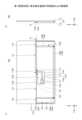
図1は、第1実施形態に係る表示装置100の前面側(横向き設置時)を示す外観斜視図である。図2は、第1実施形態に係る表示装置100(横向き設置時)の背面側を示す外観斜視図である。 [First embodiment]
(Configuration of display device 100)
FIG. 1 is an external perspective view showing the front side (when installed horizontally) of the
なお、以降の説明では、ディスプレイ121の縦方向(すなわち、短辺)に対応する方向を、上下方向(Z軸方向)とする。また、ディスプレイ121の横方向(すなわち、長辺)に対応する方向を、横幅方向および左右方向(Y軸方向)とする。また、ディスプレイ121の奥行き方向に対応する方向を、前後方向(X軸方向)とする。 In the following description, the direction corresponding to the vertical direction (that is, the short side) of the
但し、ディスプレイの背面側(X軸負側)から視て左側となる方向(Y軸正方向)を左方向とし、ディスプレイの背面側(X軸負側)から視て右側となる方向(Y軸負方向)を右方向とする。 However, the left direction (Y-axis positive direction) when viewed from the back side of the display (X-axis negative side) is the left direction, and the right direction (Y-axis (negative direction) is the right direction.
図1および図2に示す表示装置100は、前面(X軸正側の面)にディスプレイ121の表示面121Aを有し、ケーブル10を介して外部機器(例えば、ノートパソコン、スマートフォン、ACアダプタをはじめとする電源等)に接続され、外部機器からケーブル10を介して送信された各種画像(動画、静止画等)を、ディスプレイ121の表示面121Aによって表示することが可能である。すなわち、表示装置100は、バッテリ内蔵且つ可搬性を有する薄型の表示装置であり、外部機器とともに持ち運ばれて、使用時に外部機器と接続されることにより、外部機器の拡張ディスプレイとして利用可能である。 The
図1および図2に示すように、表示装置100は、当該表示装置100の外形状をなす、樹脂製且つ中空構造の筐体110を備える。筐体110は、薄部111および厚部112を有する。 As shown in FIGS. 1 and 2, the
薄部111は、筐体110の前面側(Z軸正側)を構成する薄板状の部分である。薄部111は、前方(X軸正方向)または後方(X軸負方向)からの平面視において横長の長方形状を有する。薄部111は、奥行き方向(X軸方向)の厚さが比較的薄い部分である。薄部111には、ディスプレイ121が設けられている。薄部111の前面(X軸正側の面)には、矩形状の開口部111Aが形成されており、当該開口部111Aから、ディスプレイ121の表示面121Aが露出している。なお、ディスプレイ121としては、例えば、有機EL(Electro Luminescence)ディスプレイ、液晶ディスプレイ等が用いられる。 The
なお、薄部111において、ディスプレイ121の表示面121Aには、タッチセンサ122が重ねて設けられている。タッチセンサ122は、各種入力操作(例えば、選択操作、手書き入力操作等)を受け付ける。タッチセンサ122としては、例えば、静電容量方式のタッチパネル等を用いることができる。 Note that in the
厚部112は、筐体110の背面側(X軸負側)を構成する板状の部分であり、薄部111の背面の下部から後方に突出して設けられている。厚部112は、奥行き方向(X軸方向)の厚さが比較的厚い部分である。厚部112は、後方(X軸負方向)からの平面視において横長の長方形状を有する。但し、厚部112は、後方(X軸負方向)からの平面視において、薄部111からはみ出さないように、薄部111の領域内に収まる上下幅および左右幅を有する。厚部112には、メイン基板131、操作基板132、バッテリ133(いずれも図9参照)等が収容されている。また、厚部112の背面には、ケーブル10のコネクタ11が接続されるインタフェース部123(図3参照)が設けられている。また、厚部112の背面には、スタンド136が設けられている。 The
(表示装置100の背面の構成)
図3は、第1実施形態に係る表示装置100の背面図および側面図である。図3(a)は、第1実施形態に係る表示装置100の背面図である。図3(b)は、第1実施形態に係る表示装置100の側面図である。 (Configuration of the back side of the display device 100)
FIG. 3 is a rear view and a side view of the
図3に示すように、筐体110の厚部112の背面には、凹部113が形成されている。凹部113は、前方(X軸正方向)に向かって一定の深さを有して凹んだ部分である。図3に示す例では、凹部113は、後方からの平面視において矩形状を有するが、凹部113の形状はこれに限らない。凹部113は、厚部112の厚み方向に伸びた複数の壁部113Aと、壁部113Aと交差する方向と平行な底部113Cと、を有する。 As shown in FIG. 3, a
そして、図3に示すように、インタフェース部123は、厚部112の凹部113内に露出して設けられている。特に、図3に示す例では、インタフェース部123は、厚部112の凹部113のY軸正側の壁部113Aから、凹部113内に露出して設けられている。 As shown in FIG. 3, the
これにより、第1実施形態に係る表示装置100は、図3に示すように、ケーブル10の一端部に設けられているコネクタ11を、凹部113内に配置された状態で、インタフェース部123に接続することができる。 As a result, the
すなわち、第1実施形態に係る表示装置100は、ケーブル10のコネクタ11を、筐体110の側面から突出することなく、インタフェース部123に接続することができる。 That is, the
このため、第1実施形態に係る表示装置100によれば、当該表示装置100と外部機器とを真横に並べて配置することができる。 Therefore, according to the
また、第1実施形態に係る表示装置100によれば、ケーブル10のコネクタ11への突発的な負荷を防ぐことができるため、インタフェース部123が破損するリスクを低減することができる。 Further, according to the
なお、ケーブル10としては、例えば、USB(Universal Serial Bus)ケーブル、HDMI(High-Definition Multimedia Interface)(登録商標)ケーブル等が挙げられる。インタフェース部123には、ケーブル10のコネクタ11に適合する形状を有するものが用いられる。 Note that examples of the
なお、凹部113の深さ(X軸方向の深さ)は、コネクタ11の厚さおよびケーブル10の外径よりも大きくなっている。これにより、第1実施形態に係る表示装置100は、図3(b)に示すように、インタフェース部123が、凹部113内のケーブル10(コネクタ11を含む)を、厚部112の背面よりも外側(X軸負側)にはみ出さずに接続可能である。 Note that the depth of the recess 113 (depth in the X-axis direction) is greater than the thickness of the
これにより、第1実施形態に係る表示装置100によれば、厚部112の背面側からの、ケーブル10のコネクタ11への突発的な負荷を防ぐことができる。 Thereby, according to the
また、図3に示すように、厚部112は、ケーブル10を凹部113から厚部112の上側に引き出し可能な引き出し口113Bを有する。具体的には、引き出し口113Bは、凹部113の右上側(Z軸正側かつY軸負側)の角部から、上方(Z軸正方向)に延びて厚部112の上側の空間に繋がる溝状を有する。引き出し口113Bの深さ(X軸方向の深さ)は、凹部113の深さ(X軸方向の深さ)と同じである。 Further, as shown in FIG. 3, the
これにより、第1実施形態に係る表示装置100によれば、ケーブル10を厚部112の背面よりも外側(X軸負側)にはみ出すことなく、ケーブル10を凹部113から厚部112の上側に引き出すことができる。 As a result, according to the
さらに、図3に示すように、厚部112は、引き出し口113Bにケーブル10を留める留め具114を有する。具体的には、留め具114は、引き出し口113Bを左右方向(Y軸方向)に跨いだ状態で、当該留め具114の左右方向(Y軸方向)の両端部を、嵌め込み方式によって厚部112に固定できるようになっている。 Further, as shown in FIG. 3, the
留め具114は、両端部のうちの少なくとも一方が、厚部112に形成されている嵌合孔(図示省略)に対して着脱可能に構成されている。これにより、表示装置100は、留め具114の両端部のうちの少なくとも一方が、厚部112に形成されている嵌合孔から引き抜かれることにより、引き出し口113Bを開放して、当該引き出し口113Bにケーブル10を配線することができる。そして、表示装置100は、留め具114の両端部のうちの少なくとも一方が、厚部112に形成されている嵌合孔に嵌め込まれることにより、引き出し口113Bを閉塞して、当該引き出し口113Bにケーブル10を留めることができる。 At least one of both ends of the
このように、第1実施形態に係る表示装置100によれば、ケーブル10が引き出し口113Bから抜け落ちないように、留め具114によって引き出し口113Bにケーブル10を留めることができる。また、第1実施形態に係る表示装置100によれば、ケーブル10に引っ張られる等の負荷が生じた場合であっても、当該負荷を留め具114によって受け止めることができるため、インタフェース部123が破損するリスクを低減することができる。 In this way, according to the
また、図3に示すように、厚部112は、当該厚部112の上端面112Aにより、引き出し口113Bから引き出されたケーブル10の配設経路を、当該上端面112Aに沿ってガイド可能である。 Further, as shown in FIG. 3, the
これにより、第1実施形態に係る表示装置100は、引き出し口113Bから引き出されたケーブル10を、所定の配設経路上に容易に配設することができる。 Thereby, the
また、図3に示すように、厚部112は、当該厚部112の上端面112Aによって配設経路がガイドされたケーブル10を保持可能なクランプ115を有する。 Further, as shown in FIG. 3, the
これにより、第1実施形態に係る表示装置100は、引き出し口113Bから引き出されたケーブル10を、所定の配設経路上で、確実に保持することができる。 Thereby, the
なお、図3に示す例では、厚部112は、引き出し口113Bよりも右側(Y軸負側)のケーブル10の配設経路と、引き出し口113Bよりも左側(Y軸正側)のケーブル10の配設経路とに、それぞれ2つのクランプ115を有する。 In the example shown in FIG. 3, the
これにより、第1実施形態に係る表示装置100は、引き出し口113Bからのケーブル10の引き出し方向を、左方(Y軸正方向)にした場合と、右方(Y軸負方向)にした場合とのいずれにおいても、2つのクランプ115によって、ケーブル10を配設経路上で確実に保持することができる。 As a result, the
なお、図3に示す例では、厚部112の背面において、インタフェース部123は、左右方向(Y軸方向)における中央部よりも左側(Y軸正側)に設けられており、一方、引き出し口113Bは、左右方向(Y軸方向)における中央部に設けられている。 In the example shown in FIG. 3, on the back surface of the
これにより、第1実施形態に係る表示装置100は、インタフェース部123に接続されたケーブル10を、無理なく折り曲げて、引き出し口113B(すなわち、左右方向(Y軸方向)における中央部)から厚部112の上側に引き出すことができる。 As a result, the
また、第1実施形態に係る表示装置100は、引き出し口113Bからのケーブル10の引き出し方向を、左方(Y軸正方向)および右方(Y軸負方向)のいずれとすることもできる。 Further, in the
ここで、第1実施形態に係る表示装置100は、左右方向(Y軸方向)における中央部に引き出し口113Bを設けたために、引き出し口113Bからのケーブル10の引き出し方向を、左方(Y軸正方向)にした場合と、右方(Y軸負方向)にした場合とで、ケーブル10の厚部112の上端面112Aに沿ってガイドされる部分の長さを、等しくすることができ、すなわち、ケーブル10の筐体110から外側に引き出される部分の長さを、等しくすることができる。このため、第1実施形態に係る表示装置100は、接続対象の外部機器を左方および右方のいずれに配置した場合であっても、必要となるケーブル10の長さを一定の長さとすることができる。 Here, in the
また、図3に示す例では、厚部112の凹部113のY軸正側の壁部113Aには、2つのインタフェース部123が上下方向(Z軸方向)に並べて設けられている。これにより、第1実施形態に係る表示装置100は、凹部113内で、2本のケーブル10を接続することができ、2本のケーブル10を介して、2つの外部機器を接続できるようになっている。さらに、図3に示す例では、引き出し口113Bは、2本のケーブル10を並べて引き出すことができるように、(ケーブル10の外径×2)よりも大きい左右幅を有する。 Further, in the example shown in FIG. 3, two
また、図3(a)に示すように、厚部112の左側(Y軸正側)の側面には、スイッチ134およびスイッチ135が設けられている。スイッチ134およびスイッチ135は、例えば、電源ボタン、選択ボタン、確定ボタン、戻るボタン等である。 Further, as shown in FIG. 3A, a
また、図3に示すように、第1実施形態に係る表示装置100は、厚部112にスタンド136が収納可能に設けられている。図3に示すように、スタンド136は、上端部に回転軸136Xを有しており、回転軸136Xを中心として回動可能に設けられている。 Further, as shown in FIG. 3, in the
また、スタンド136は、矩形枠状を有している。具体的には、スタンド136は、左右一対の短枠部136Aと、左右一対の短枠部136Aの下端部同士を連結する長枠部136Bとを有し、上部(左右一対の短枠部136Aの上端部の間の部分)が開口した矩形枠状(いわゆるU字状)を有する。 Further, the
一方、厚部112には、スタンド136と同形状の収納溝112Bが形成されている。このため、第1実施形態に係る表示装置100は、スタンド136を厚部112の背面から突出することなく収納溝112Bに収納することができる。 On the other hand, a
(表示装置100の設置例)
図4は、第1実施形態に係る表示装置100が備えるスタンド136の開閉動作を示す図である。図5は、第1実施形態に係る表示装置100の縦向きの設置例を示す図である。 (Example of installation of display device 100)
FIG. 4 is a diagram showing the opening/closing operation of the
図4に示すように、スタンド136は、上端部に設けられた回転軸136Xを中心として回動することにより、開閉動作することができる。スタンド136は、開閉動作することにより、開き角度を任意の角度とすることができる。図4では、一例として、開き角度が90°である状態のスタンド136を示している。 As shown in FIG. 4, the
但し、スタンド136は、開き角度を90°以上の任意の角度とすることができ、開き角度を最大で180°とすることができる。 However, the
また、スタンド136は、開き角度を0°とすることにより、厚部112に形成されている収納溝112Bに収納することができる。 Further, the
また、第1実施形態に係る表示装置100は、設置面に対して、横向き設置と縦向き設置とのいずれも可能であり、横向き設置時と縦向き設置時とのいずれにおいても、スタンド136が、当該表示装置100を支持可能である。 Further, the
例えば、図1および図2に示すように、第1実施形態に係る表示装置100は、スタンド136を収納状態から回動させて開いた状態とすることにより、横向き状態(筐体110の長辺部分が重力方向における下向きの状態)で、筐体110を設置面に自立させることができる。この場合、第1実施形態に係る表示装置100は、スタンド136の開き角度を調整することで、設置面に対する筐体110の傾きを調整することができる。 For example, as shown in FIGS. 1 and 2, the
特に、第1実施形態に係る表示装置100は、スタンド136の開き角度が無段階に調整可能となっているため、設置面に対する筐体110の傾きを無段階に調整することができ、よって、表示装置100の横向き設置時の自由度を向上させることができる。 In particular, in the
なお、第1実施形態に係る表示装置100は、公知の負荷付与手段(図示省略)によって、開閉動作に対して一定の負荷が付与されている。これにより、第1実施形態に係る表示装置100は、スタンド136の開き角度が手動によって無段階に調整可能でありながら、スタンド136によって支持されているときには、スタンド136が意図せずに開閉動作してしまうこと(すなわち、表示装置100の設置角度が変化してしまうこと)を抑制することができる。 Note that in the
また、図5に示すように、第1実施形態に係る表示装置100は、スタンド136を収納状態から回動させて開いた状態とすることにより、縦向き状態(筐体110の短辺部分が重力方向における下向きの状態)で、筐体110を設置面に自立させることができる。この場合、第1実施形態に係る表示装置100は、スタンド136の開き角度を90°とすることで、筐体110の短辺方向における中央で、筐体110をスタンド136によって安定的に支持することができる。 Further, as shown in FIG. 5, the
なお、第1実施形態に係る表示装置100は、筐体110の向きをセンサによって検知し、ディスプレイ121に表示される表示画面の向きを、筐体110の向きに合わせて自動的に回転させるようにしてもよい。または、第1実施形態に係る表示装置100は、ディスプレイ121に表示される表示画面の向きを、ユーザが手動で設定することにより、回転させるようにしてもよい。 Note that the
なお、図3に示すように、スタンド136の回転軸136Xは、厚部112の上端面112Aよりも下側に設けられている。このため、第1実施形態に係る表示装置100は、スタンド136の開閉動作が、厚部112の上端面112Aに沿って配設されたケーブル10に干渉しないようになっている。 Note that, as shown in FIG. 3, the
ここで、第1実施形態に係る表示装置100は、ケーブル10のコネクタ11を、厚部112の背面に形成されている凹部113内でインタフェース部123に接続することができ、さらに、コネクタ11およびケーブル10の一部を、凹部113内に収納できるようになっている。 Here, in the
これにより、第1実施形態に係る表示装置100は、横向き設置時および縦向き設置時のいずれにおいても、当該表示装置100を正面側から視たときに、コネクタ11を筐体110の外側に突出しないようにすることができ、すなわち、コネクタ11が視認されないようにすることができる。 As a result, the
また、第1実施形態に係る表示装置100は、図2に示すように、横向き設置時には、ケーブル10を、引き出し口113Bから厚部112の外側(Z軸正側)に引き出して、厚部112の上端面112Aに沿って配線することができる。 Further, as shown in FIG. 2, when the
また、第1実施形態に係る表示装置100は、図5に示すように、縦向き設置時には、ケーブル10を、引き出し口113Bから厚部112の外側(Z軸正側)に引き出して、厚部112の上端面112Aに沿って垂れ下がるように配線することができ、さらに、スタンド136の短枠部136Aと設置面との間の三角形状の隙間A(図5参照)内を通り抜けるように配線することができる。 Further, as shown in FIG. 5, when the
このように、第1実施形態に係る表示装置100は、横向き設置時および縦向き設置時のいずれにおいても、ケーブル10を装置外装に沿わせるように配線ができるため、ケーブル10の取り回しを容易に行うことができる。 In this way, the
また、第1実施形態に係る表示装置100は、スタンド136が、凹部113を取り囲む矩形枠状を有するため、コネクタ11を凹部113内のインタフェース部123に接続して配線する作業の妨げにならず、ユーザがケーブル10の接続および配線作業を容易に行うことができる。 Furthermore, in the
また、第1実施形態に係る表示装置100は、スタンド136が、下側の左右両方の角部(「設置面との接地部」の一例)に、弾性部材137を有する。弾性部材137としては、例えば、ゴム、シリコン等が用いられる。これにより、第1実施形態に係る表示装置100は、横向き設置時および縦向き設置時のいずれにおいても、設置面に対するスタンド136のグリップ力を高めることができ、よって、設置安定性を高めることができる。 In addition, in the
なお、スタンド136に対する弾性部材137の設置方法は、スタンド136を被覆する方法、スタンド136の表面に固定する方法、スタンド136の切り欠き部に嵌め込む方法等、如何なる方法であってもよい。また、弾性部材137の形状は、チューブ状、ブロック状(例えば、キューブ状、ボール状等)、板状等、如何なる形状であってもよい。 Note that the
(表示装置100の横向き設置時に関する設計要件)
図6は、第1実施形態に係る表示装置100の横向き設置時に関する設計要件を示す図である。 (Design requirements regarding horizontal installation of display device 100)
FIG. 6 is a diagram illustrating design requirements regarding horizontal installation of the
図6に示すように、第1実施形態に係る表示装置100は、スタンド136が、筐体110の短辺方向(Z軸方向)における中央に回転軸136Xを有する。 As shown in FIG. 6, in the
これにより、第1実施形態に係る表示装置100は、図1および図2に示すように横向き設置する場合の設置安定性を向上させることができる。 Thereby, the
また、これにより、第1実施形態に係る表示装置100は、図5に示すように縦向き設置する場合においても、スタンド136を筐体110の短辺方向における中央に位置させることができるため、スタンド136によって筐体110をバランス良く安定的に支持することができる。 Further, as a result, even when the
また、第1実施形態に係る表示装置100は、スタンド136の短辺方向(Z軸方向)の幅hが、筐体110の短辺方向(Z軸方向)の幅Hの0.5倍となっている。 Furthermore, in the
これにより、第1実施形態に係る表示装置100は、スタンド136の長枠部136Bを可能な限り筐体110から後方(X軸負方向)に離れて接地させることができ、よって、図1および図2に示すように横向き設置する場合の設置安定性を、さらに向上させることができる。 Thereby, the
但し、第1実施形態に係る表示装置100は、他部品との干渉等により、スタンド136の短辺方向(Z軸方向)の幅hを、筐体110の短辺方向(Z軸方向)の幅Hの0.5倍とすることができない場合、少なくとも、スタンド136の短辺方向(Z軸方向)の幅hを、筐体110の短辺方向(Z軸方向)の幅Hの0.4倍とすれば、横向き設置する場合の十分な設置安定性を確保することができる。 However, in the
したがって、第1実施形態に係る表示装置100は、スタンド136の短辺方向(Z軸方向)の幅hは、筐体110の短辺方向(Z軸方向)の幅Hの0.4倍以上且つ0.5倍以下であることが好ましい。 Therefore, in the
(表示装置100の縦向き設置時に関する設計要件)
図7および図8は、第1実施形態に係る表示装置100の縦向き設置時に関する設計要件を示す図である。 (Design requirements regarding vertical installation of display device 100)
FIGS. 7 and 8 are diagrams showing design requirements regarding the vertical installation of the
図8に示すように、スタンド136の左右幅W2は、筐体110の左右幅W1よりも狭められている。これにより、図8に示すように、第1実施形態に係る表示装置100は、スタンド136の左右両外側において、筐体110の端部と、スタンド136の端部との間に、距離Xを有するものとなっている。 As shown in FIG. 8, the horizontal width W2 of the
ここで、一般的に、ノートパソコン等のディスプレイの設置面に対する設置角度は、60°~75°の範囲内であることが好ましいとされている。 Here, it is generally said that the installation angle of the display of a notebook computer or the like with respect to the installation surface is preferably within the range of 60° to 75°.
図7に示すように、第1実施形態に係る表示装置100は、縦置き設置時において、設置面20に対する設置角度をθBとし、筐体110の長辺方向(Y軸方向)における、筐体110の端部から、スタンド136の端部までの距離をXとし、スタンド136の短辺方向の幅をhとした場合、以下の式(1),(2)が成り立つ。 As shown in FIG. 7, when the


ここで、スタンド136の短辺方向の幅をhは、下記式(3)で表される。 Here, the width h of the

よって、第1実施形態に係る表示装置100は、縦置き設置時において、設置面20に対する設置角度θBを、60°~75°の範囲内とするためには、図8に示すように、筐体110の長辺方向(Y軸方向)における、筐体110の端部から、スタンド136の端部までの距離Xを、下記式(4)を満たすように設定すればよい。 Therefore, when the

すなわち、第1実施形態に係る表示装置100は、筐体110の長辺方向(Y軸方向)において、筐体110の端部から、スタンド136の端部までの距離Xは、筐体110の短辺方向(Z軸方向)における幅Hの0.1072倍以上且つ0.2887倍以下であることが好ましい。 That is, in the
これにより、第1実施形態に係る表示装置100は、横置き設置時および縦置き設置時のいずれにおいても、設置面20に対する設置角度を、ユーザが使用し易い設置角度である60°~75°の範囲内とすることができる。 As a result, the
したがって、第1実施形態に係る表示装置100によれば、ユーザの設置性およびユーザビリティ性を向上させることができる。さらに、第1実施形態に係る表示装置100によれば、スタンド136が筐体110に内蔵されており、筐体110とは別にスタンドを持ち運ぶことが不要になるため、ユーザの可搬性を向上させることができる。 Therefore, according to the
(表示装置100の内部構成の一例)
図9は、第1実施形態に係る表示装置100の内部構成の一例を示す図である。 (Example of internal configuration of display device 100)
FIG. 9 is a diagram showing an example of the internal configuration of the
図9に示すように、第1実施形態に係る表示装置100は、左右方向(Y軸方向)における中央部に引き出し口113Bを設けている。これにより、第1実施形態に係る表示装置100は、引き出し口113Bからのケーブル10の引き出し方向を、左方(Y軸正方向)にした場合と、右方(Y軸負方向)にした場合とで、ケーブル10の厚部112の上端面112Aに沿ってガイドされる部分の長さを、いずれもW1/2(但し、W1は筐体110の左右幅)とすることができる。 As shown in FIG. 9, the
また、図9に示すように、第1実施形態に係る表示装置100は、厚部112の内部に、メイン基板131、操作基板132、およびバッテリ133を有する。 Further, as shown in FIG. 9, the
メイン基板131は、インタフェース部123と接続されており、各種電子部品が実装されることにより、表示装置100の全体の制御を行う制御回路が構築される。 The
操作基板132は、厚部112の左側(Y軸正側)の側面に設けられているスイッチ134およびスイッチ135と接続されており、各種電子部品が実装されることにより、スイッチ134およびスイッチ135の操作を制御する制御回路が構築される。 The
バッテリ133は、表示装置100の駆動用の電力を蓄電する。バッテリ133には、充電可能な各種二次電池(例えば、リチウムイオン電池、リチウムポリマー電池等)が用いられる。なお、表示装置100は、外部機器からケーブル10およびインタフェース部123を介して給電されることにより、バッテリ133を充電できるようになっている。 The
ここで、図9に示すように、第1実施形態に係る表示装置100は、厚部112にスタンド136および収納溝112Bを設けたことにより、厚部112の内部に、互いに分断された3つの内部領域116A,116B,116Cが形成されている。 Here, as shown in FIG. 9, in the
内部領域116Aは、スタンド136よりも左側(Y軸正側)の内部領域である。内部領域116Aには、操作基板132が配置されていることで、当該内部領域116Aが有効利用されている。 The
内部領域116Bは、スタンド136の左右一対の短枠部136Aの間の内部領域である。内部領域116Bには、凹部113を間に挟んで、メイン基板131およびバッテリ133が配置されていることで、当該内部領域116Bが有効利用されている。 The
内部領域116Cは、スタンド136よりも右側(Y軸負側)の内部領域である。内部領域116Cには、構成部品が配置されていないが、何らかの構成部品を配置することで、当該内部領域116Cが有効利用されてもよい。 The internal area 116C is an internal area on the right side (Y-axis negative side) of the
〔第2実施形態〕
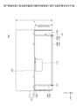
図10は、第2実施形態に係る表示装置100-2(横向き設置時)の背面側を示す外観斜視図である。図11は、第2実施形態に係る表示装置100-2の縦向きの設置例を示す図である。 [Second embodiment]
FIG. 10 is an external perspective view showing the rear side of a display device 100-2 (when installed horizontally) according to the second embodiment. FIG. 11 is a diagram showing an example of vertical installation of the display device 100-2 according to the second embodiment.
第2実施形態に係る表示装置100-2は、スタンド136の代わりに、スタンド136-2を備える点で、第1実施形態に係る表示装置100と異なる。 The display device 100-2 according to the second embodiment differs from the
スタンド136-2は、いわゆるキックスタンドであり、平板状を有し、且つ、平面視にて矩形状を有する点で、スタンド136と異なる。 The stand 136-2 is a so-called kickstand, and differs from the
但し、スタンド136-2の外形状のサイズは、スタンド136の外形状のサイズと同一である。また、スタンド136-2は、スタンド136と同様に、上端部に回転軸136Xを有しており、回転軸136Xを中心として回動可能に設けられている。 However, the external size of the stand 136-2 is the same as the external size of the
これにより、スタンド136-2は、スタンド136と同様に、表示装置100の横置き設置時および縦置き設置時のいずれにおいても、表示装置100を支持することができる。 Thus, like the
さらに、スタンド136-2は、平板状を有するため、収納時に、厚部112の背面と重なり、且つ、凹部113を覆い隠すことができ、厚部112の背面のデザイン性向上等に寄与することができる。 Furthermore, since the stand 136-2 has a flat plate shape, it can overlap the back surface of the
(表示装置100-2の設置に関する設計要件)
図12は、第2実施形態に係る表示装置100-2の設置に関する設計要件を示す図である。 (Design requirements for installation of display device 100-2)
FIG. 12 is a diagram showing design requirements regarding installation of the display device 100-2 according to the second embodiment.
第2実施形態に係る表示装置100-2における、横向き設置時に関する設計要件、および、縦向き設置時に関する設計要件は、第1実施形態に係る表示装置100と同じである。 The design requirements regarding the horizontal installation and the design requirements regarding the vertical installation of the display device 100-2 according to the second embodiment are the same as those of the
例えば、図12に示すように、第2実施形態に係る表示装置100-2は、スタンド136-2が、筐体110の短辺方向(Z軸方向)における中央に回転軸136Xを有する。 For example, as shown in FIG. 12, in the display device 100-2 according to the second embodiment, the stand 136-2 has a
これにより、第2実施形態に係る表示装置100-2は、図10に示すように横向き設置する場合の設置安定性を向上させることができる。 Thereby, the display device 100-2 according to the second embodiment can improve installation stability when installed horizontally as shown in FIG.
また、第2実施形態に係る表示装置100-2は、スタンド136-2の短辺方向(Z軸方向)の幅hが、筐体110の短辺方向(Z軸方向)の幅Hの0.5倍となっている。 Further, in the display device 100-2 according to the second embodiment, the width h of the stand 136-2 in the short side direction (Z-axis direction) is 0 of the width H of the
好ましくは、第2実施形態に係る表示装置100-2は、スタンド136-2の短辺方向(Z軸方向)の幅hが、筐体110の短辺方向(Z軸方向)の幅Hの0.4倍以上且つ0.5倍以下となっていることである。 Preferably, in the display device 100-2 according to the second embodiment, the width h of the stand 136-2 in the short side direction (Z-axis direction) is equal to the width H of the
これにより、第2実施形態に係る表示装置100-2は、スタンド136の下側(Z軸負側)の長辺部分(設置面との接地部)を可能な限り筐体110から後方(X軸負方向)に離れて接地させることができ、よって、図10に示すように横向き設置する場合の設置安定性を、さらに向上させることができる。 As a result, the display device 100-2 according to the second embodiment moves the long side portion (grounding portion with the installation surface) of the lower side (Z-axis negative side) of the
また、図12に示すように、第2実施形態に係る表示装置100-2は、筐体110の長辺方向(Y軸方向)における、筐体110の端部から、スタンド136-2の端部までの距離Xを、上記式(4)を満たすように設定すればよい。 In addition, as shown in FIG. 12, the display device 100-2 according to the second embodiment is arranged from the end of the
すなわち、第2実施形態に係る表示装置100-2は、筐体110の長辺方向(Y軸方向)において、筐体110の端部から、スタンド136-2の端部までの距離Xは、筐体110の短辺方向(Z軸方向)における幅Hの0.1072倍以上且つ0.2887倍以下であることが好ましい。 That is, in the display device 100-2 according to the second embodiment, the distance X from the end of the
これにより、第2実施形態に係る表示装置100-2は、横置き設置時および縦置き設置時のいずれにおいても、設置面20に対する設置角度を、ユーザが使用し易い設置角度である60°~75°の範囲内とすることができる。 As a result, the display device 100-2 according to the second embodiment can change the installation angle with respect to the
したがって、第2実施形態に係る表示装置100-2によれば、ユーザの設置性およびユーザビリティ性を向上させることができる。さらに、第2実施形態に係る表示装置100-2によれば、スタンド136-2が筐体110に内蔵されており、筐体110とは別にスタンドを持ち運ぶことが不要になるため、ユーザの可搬性を向上させることができる。 Therefore, according to the display device 100-2 according to the second embodiment, ease of installation and usability for the user can be improved. Furthermore, according to the display device 100-2 according to the second embodiment, the stand 136-2 is built into the
また、第2実施形態に係る表示装置100-2は、スタンド136-2が、下側の左右両方の角部(「設置面との接地部」の一例)に、弾性部材137を有する。弾性部材137としては、例えば、ゴム、シリコン等が用いられる。これにより、第2実施形態に係る表示装置100-2は、横向き設置時および縦向き設置時のいずれにおいても、設置面に対するスタンド136-2のグリップ力を高めることができ、よって、設置安定性を高めることができる。 In addition, in the display device 100-2 according to the second embodiment, the stand 136-2 includes
以上、本発明の好ましい実施形態について詳述したが、本発明はこれらの実施形態に限定されるものではなく、特許請求の範囲に記載された本発明の要旨の範囲内において、種々の変形又は変更が可能である。 Although the preferred embodiments of the present invention have been described in detail above, the present invention is not limited to these embodiments, and various modifications and variations can be made within the scope of the gist of the present invention as described in the claims. Changes are possible.
例えば、本発明は、実施形態で説明したように、筐体が薄部と厚部とを有する表示装置に好適に適用可能であるが、これに限らず、筐体が薄部と厚部とを有しない(すなわち、全体的に一定の厚さを有する)表示装置にも適用可能である。 For example, as described in the embodiments, the present invention is suitably applicable to a display device in which the casing has a thin part and a thick part, but is not limited thereto. It is also applicable to display devices that do not have a thickness (that is, have an overall constant thickness).
また、例えば、本発明は、実施形態で説明したように、筐体の厚部に凹部およびインタフェース部を有する表示装置に好適に適用可能であるが、これに限らず、筐体の厚部に凹部およびインタフェース部を有しない表示装置にも適用可能である。 Further, for example, as described in the embodiments, the present invention is suitably applicable to a display device having a recess and an interface portion in the thick part of the housing, but is not limited to this. It is also applicable to a display device that does not have a recessed portion or an interface portion.
10 ケーブル
11 コネクタ
20 設置面
100,100-2 表示装置
110 筐体
111 薄部
111A 開口部
112 厚部
112A 上端面
112B 収納溝
113 凹部
113A 壁部
113B 引き出し口
113C 底部
114 留め具
115 クランプ
116A,116B,116C 内部領域
121 ディスプレイ
121A 表示面
122 タッチセンサ
123 インタフェース部
131 メイン基板
132 操作基板
133 バッテリ
134,135 スイッチ
136,136-2 スタンド
136A 短枠部
136B 長枠部
136X 回転軸
137 弾性部材 10
Claims (11)
Translated fromJapanese前記筐体の前面から露出する表示面を有するディスプレイと、
前記筐体の背面に設けられ、開閉角度が可変なスタンドと
を備え、
前記スタンドは、
前記筐体の短辺方向における中央に回転軸を有し、
前記筐体の長辺方向における当該スタンドの幅が、前記長辺方向における前記筐体の幅よりも狭い
ことを特徴とする表示装置。 a casing having a rectangular shape in plan view;
a display having a display surface exposed from the front of the casing;
a stand provided on the back of the casing and having a variable opening/closing angle;
The stand is
having a rotation axis at the center of the housing in the short side direction;
A display device characterized in that the width of the stand in the long side direction of the housing is narrower than the width of the housing in the long side direction.
前記ディスプレイが設けられた薄部と、
前記薄部の背面から後方に突出して設けられた厚部と
を有し、
前記スタンドは、前記厚部の背面に設けられている
ことを特徴とする請求項1に記載の表示装置。 The casing is
a thin portion provided with the display;
and a thick part provided to protrude rearward from the back surface of the thin part,
The display device according to claim 1, wherein the stand is provided on a back surface of the thick portion.
前記インタフェース部は、前記厚部の凹部内に設けられている
ことを特徴とする請求項2に記載の表示装置。 Equipped with an interface section to which a cable connector is connected for connecting to external equipment,
The display device according to claim 2, wherein the interface portion is provided within a recessed portion of the thick portion.
設置面に対して前記表示装置が横向き設置時と、前記設置面に対して前記表示装置が縦向き設置時とのいずれにおいても、前記表示装置を支持可能である
ことを特徴とする請求項3に記載の表示装置。 The stand is
Claim 3, wherein the display device can be supported both when the display device is installed horizontally with respect to the installation surface and when the display device is installed vertically with respect to the installation surface. The display device described in .
ことを特徴とする請求項3に記載の表示装置。 The display device according to claim 3, wherein the width of the stand in the short side direction is 0.4 times or more and 0.5 times or less the width of the housing in the short side direction.
ことを特徴とする請求項4または5に記載の表示装置。 In the long side direction of the housing, the distance from the end of the housing to the end of the stand is at least 0.1072 times and no more than 0.2887 times the width of the housing in the short side direction. The display device according to claim 4 or 5, characterized in that:
一対の短枠部と一つの長枠部とからなる矩形枠状を有する
ことを特徴とする請求項6に記載の表示装置。 The stand is
The display device according to claim 6, having a rectangular frame shape consisting of a pair of short frame portions and one long frame portion.
平板状を有し、収納時に前記厚部の前記背面と重なり、且つ、前記凹部を覆う
ことを特徴とする請求項6に記載の表示装置。 The stand is
The display device according to claim 6, having a flat plate shape, overlapping the back surface of the thick portion and covering the recessed portion when stored.
設置面との接地部に、弾性部材を有する
ことを特徴とする請求項4または5に記載の表示装置。 The stand is
The display device according to claim 4 or 5, further comprising an elastic member at a ground contact portion with the installation surface.
前記コネクタが、前記厚部の前記凹部内に収まるとともに、
前記ケーブルが、前記厚部の前記凹部内から、前記厚部の外部に沿うように配線される
ことを特徴とする請求項3に記載の表示装置。 When the connector of the cable is connected to the interface section,
The connector fits within the recess of the thick portion, and
The display device according to claim 3, wherein the cable is routed from inside the recess of the thick portion to along the outside of the thick portion.
枠状を有し、前記厚部において、前記インタフェース部を備える前記凹部よりも外側に配置される
ことを特徴とする請求項3または10に記載の表示装置。 The stand is
The display device according to claim 3 or 10, wherein the display device has a frame shape and is arranged in the thick portion outside the recessed portion including the interface portion.
Priority Applications (3)
| Application Number | Priority Date | Filing Date | Title |
|---|---|---|---|
| JP2022145425AJP2024040823A (en) | 2022-09-13 | 2022-09-13 | display device |
| US18/228,676US20240094780A1 (en) | 2022-09-13 | 2023-08-01 | Display device |
| EP23195784.6AEP4339735A1 (en) | 2022-09-13 | 2023-09-06 | Display device |
Applications Claiming Priority (1)
| Application Number | Priority Date | Filing Date | Title |
|---|---|---|---|
| JP2022145425AJP2024040823A (en) | 2022-09-13 | 2022-09-13 | display device |
Publications (1)
| Publication Number | Publication Date |
|---|---|
| JP2024040823Atrue JP2024040823A (en) | 2024-03-26 |
Family
ID=87933615
Family Applications (1)
| Application Number | Title | Priority Date | Filing Date |
|---|---|---|---|
| JP2022145425APendingJP2024040823A (en) | 2022-09-13 | 2022-09-13 | display device |
Country Status (3)
| Country | Link |
|---|---|
| US (1) | US20240094780A1 (en) |
| EP (1) | EP4339735A1 (en) |
| JP (1) | JP2024040823A (en) |
Cited By (1)
| Publication number | Priority date | Publication date | Assignee | Title |
|---|---|---|---|---|
| EP4617425A1 (en) | 2024-03-15 | 2025-09-17 | Seiko Epson Corporation | Recycled sheet generation system, method for generating recycled sheet, and program |
Families Citing this family (2)
| Publication number | Priority date | Publication date | Assignee | Title |
|---|---|---|---|---|
| USD1052578S1 (en)* | 2023-10-19 | 2024-11-26 | Juanzhi Chen | Portable display |
| USD1090538S1 (en)* | 2024-10-31 | 2025-08-26 | Shenzhen Renmei Plastic Electronics Co., Ltd. | Portable monitor |
Family Cites Families (14)
| Publication number | Priority date | Publication date | Assignee | Title |
|---|---|---|---|---|
| DE4028645A1 (en)* | 1990-09-09 | 1992-03-12 | Licinvest Ag | FRAME FOR THE EXPOSURE OF IMAGES |
| US6713678B2 (en)* | 2002-03-11 | 2004-03-30 | Sun Microsystems, Inc. | Cable management system for electronic devices such as flat panel monitors |
| US7459634B2 (en)* | 2005-10-17 | 2008-12-02 | Hewlett-Packard Development Company, L.P. | System and method for managing cables |
| US7299580B2 (en)* | 2005-11-22 | 2007-11-27 | Inventec C'orporation | Mounting structure for a display |
| JP5681894B2 (en)* | 2010-08-31 | 2015-03-11 | パナソニックIpマネジメント株式会社 | Electronic equipment |
| WO2013062920A1 (en)* | 2011-10-24 | 2013-05-02 | Clo Systems, Llc. | Cable management system |
| US9460029B2 (en) | 2012-03-02 | 2016-10-04 | Microsoft Technology Licensing, Llc | Pressure sensitive keys |
| CN107906328B (en)* | 2014-09-24 | 2019-06-25 | 苏州佳世达电通有限公司 | Display module |
| US10690285B2 (en)* | 2015-05-12 | 2020-06-23 | Asustek Computer Inc. | Portable electronic device |
| US10835106B1 (en)* | 2020-02-21 | 2020-11-17 | Ambu A/S | Portable monitor |
| KR20210127402A (en)* | 2020-04-14 | 2021-10-22 | 삼성전자주식회사 | Display apparatus |
| CN116508313A (en)* | 2021-09-30 | 2023-07-28 | 京东方科技集团股份有限公司 | Complete machine structure and display device |
| JP2023128391A (en)* | 2022-03-03 | 2023-09-14 | 株式会社リコー | display device |
| US12242311B2 (en)* | 2022-03-03 | 2025-03-04 | Ricoh Company, Ltd. | Display device |
- 2022
- 2022-09-13JPJP2022145425Apatent/JP2024040823A/enactivePending
- 2023
- 2023-08-01USUS18/228,676patent/US20240094780A1/enactivePending
- 2023-09-06EPEP23195784.6Apatent/EP4339735A1/enactivePending
Cited By (1)
| Publication number | Priority date | Publication date | Assignee | Title |
|---|---|---|---|---|
| EP4617425A1 (en) | 2024-03-15 | 2025-09-17 | Seiko Epson Corporation | Recycled sheet generation system, method for generating recycled sheet, and program |
Also Published As
| Publication number | Publication date |
|---|---|
| US20240094780A1 (en) | 2024-03-21 |
| EP4339735A1 (en) | 2024-03-20 |
Similar Documents
| Publication | Publication Date | Title |
|---|---|---|
| JP2024040823A (en) | display device | |
| US10948948B2 (en) | Mobile apparatus | |
| US7277275B2 (en) | Portable computer having adjustable display | |
| US12242311B2 (en) | Display device | |
| US6032918A (en) | Multi-functional device for a display device | |
| JP4973311B2 (en) | Electronics | |
| US8964377B2 (en) | Electronic device having slide-tilt operation | |
| US20120162949A1 (en) | Display apparatus | |
| JP2012173878A (en) | Electronic apparatus | |
| EP3940284A1 (en) | Device holder and device holding system | |
| JP2020135744A (en) | Electronics | |
| CN115756098A (en) | Notebook computer with separated camera | |
| EP2472348A2 (en) | Information processing apparatus | |
| JP2022519891A (en) | Electronics | |
| EP4242789A1 (en) | Display device | |
| CN110657338B (en) | Tripod head camera | |
| JP5677402B2 (en) | Electronics | |
| JP2023128397A (en) | display device | |
| JP2023129185A (en) | display device | |
| JP6064775B2 (en) | Connector device and electronic device | |
| JP4594483B2 (en) | Electronics | |
| CN110786082A (en) | Remote controller and remote control system | |
| JP3229910U (en) | External monitor for laptop | |
| KR19990004441A (en) | Portable computer | |
| JP4940337B2 (en) | Electronics |
Legal Events
| Date | Code | Title | Description |
|---|---|---|---|
| A621 | Written request for application examination | Free format text:JAPANESE INTERMEDIATE CODE: A621 Effective date:20250724 |