JP2024034572A - Exercise index derivation device, exercise index derivation method, and exercise index derivation program - Google Patents
Exercise index derivation device, exercise index derivation method, and exercise index derivation programDownload PDFInfo
- Publication number
- JP2024034572A JP2024034572AJP2022138909AJP2022138909AJP2024034572AJP 2024034572 AJP2024034572 AJP 2024034572AJP 2022138909 AJP2022138909 AJP 2022138909AJP 2022138909 AJP2022138909 AJP 2022138909AJP 2024034572 AJP2024034572 AJP 2024034572A
- Authority
- JP
- Japan
- Prior art keywords
- impact
- index
- angular velocity
- series data
- deriving
- Prior art date
- Legal status (The legal status is an assumption and is not a legal conclusion. Google has not performed a legal analysis and makes no representation as to the accuracy of the status listed.)
- Pending
Links
Images


Landscapes
- Measurement Of The Respiration, Hearing Ability, Form, And Blood Characteristics Of Living Organisms (AREA)
Abstract
Translated fromJapaneseDescription
Translated fromJapanese本発明は、運動指標導出装置、運動指標導出方法及び運動指標導出プログラムに関する。 The present invention relates to an exercise index deriving device, an exercise index deriving method, and an exercise index deriving program.
従来、足部に加わる圧力、加速度、角速度、衝撃などの力を検出し、これらの力について指標データを算出し、この指標データを基に、足部に連なる身体部位(ひざ、下腿部、大腿部、腰部など)に加わる力の状態を表す物理量を算出する身体特性検出方法が開示されている(例えば、特許文献1参照)。 Conventionally, forces such as pressure, acceleration, angular velocity, and impact applied to the foot are detected, index data is calculated for these forces, and based on this index data, body parts connected to the foot (knees, lower legs, A physical characteristic detection method has been disclosed that calculates a physical quantity representing the state of force applied to the thigh, lower back, etc. (see, for example, Patent Document 1).
しかしながら、上記特許文献1に開示されている身体特性検出方法では、上記の物理量を算出するにあたり、足部による運動と身体部位の状態との関係を推定することにより、当該物理量を算出するため、十分な精度を得難いという問題がある。特に、足部に連なる身体部位として腰部に加わる力の状態を表す物理量を算出する場合、ひざや下腿部などに比べて、足部との相関関係が複雑になるため、上記の問題が顕著となる。 However, in the physical characteristic detection method disclosed in
本発明は、このような問題に鑑みてなされたものであり、被測定者に作用する衝撃力を示す衝撃指標を精度良く導出できるようにすることを目的とする。 The present invention has been made in view of such problems, and an object of the present invention is to enable accurate derivation of an impact index indicating the impact force acting on a person to be measured.
上記課題を解決するため、本発明に係る運動指標導出装置は、
被測定者の運動に係る指標を導出する運動指標導出装置であって、
運動期間中に角速度センサで検出された角速度に係る角速度情報に基づいて導出される衝撃に対応する時系列データを取得する取得手段と、
前記取得手段により取得された前記衝撃に対応する時系列データから前記被測定者の着地タイミングの直後に現れるピークを検出する検出手段と、
前記被測定者の着地タイミングから前記ピークに到達するタイミングまでの前記衝撃に対応する時系列データに基づいて、前記被測定者に作用する衝撃力を示す衝撃指標を導出する衝撃指標導出手段と、
を備えることを特徴とする。 In order to solve the above problems, the exercise index deriving device according to the present invention includes:
A movement index deriving device for deriving an index related to the movement of a person to be measured,
acquisition means for acquiring time-series data corresponding to an impact derived based on angular velocity information related to the angular velocity detected by the angular velocity sensor during the exercise period;
detection means for detecting a peak that appears immediately after the landing timing of the subject from the time series data corresponding to the impact acquired by the acquisition means;
Impact index deriving means for deriving an impact index indicating an impact force acting on the subject based on time series data corresponding to the impact from the timing at which the subject lands to the timing at which the peak is reached;
It is characterized by having the following.
また、上記課題を解決するため、本発明に係る運動指標導出方法は、
被測定者の運動に係る指標を導出する運動指標導出方法であって、
運動期間中に角速度センサで検出された角速度に係る角速度情報に基づいて導出される衝撃に対応する時系列データを取得する取得工程と、
前記取得工程により取得された前記衝撃に対応する時系列データから前記被測定者の着地タイミングの直後に現れるピークを検出する検出工程と、
前記被測定者の着地タイミングから前記ピークに到達するタイミングまでの前記衝撃に対応する時系列データに基づいて、前記被測定者に作用する衝撃力を示す衝撃指標を導出する衝撃指標導出工程と、
を含むことを特徴とする。 Furthermore, in order to solve the above problems, the exercise index deriving method according to the present invention includes:
A movement index derivation method for deriving an index related to the movement of a subject, the method comprising:
an acquisition step of acquiring time series data corresponding to an impact derived based on angular velocity information related to the angular velocity detected by the angular velocity sensor during the exercise period;
a detection step of detecting a peak that appears immediately after the landing timing of the subject from the time series data corresponding to the impact acquired in the acquisition step;
an impact index deriving step of deriving an impact index indicating an impact force acting on the subject based on time-series data corresponding to the impact from the timing when the subject lands to the timing when the peak is reached;
It is characterized by including.
また、上記課題を解決するため、本発明に係る運動指標導出プログラムは、
被測定者の運動に係る指標を導出する運動指標導出装置のコンピュータを、
運動期間中に角速度センサで検出された角速度に係る角速度情報に基づいて導出される衝撃に対応する時系列データを取得する取得手段、
前記取得手段により取得された前記衝撃に対応する時系列データから前記被測定者の着地タイミングの直後に現れるピークを検出する検出手段、
前記被測定者の着地タイミングから前記ピークに到達するタイミングまでの前記衝撃に対応する時系列データに基づいて、前記被測定者に作用する衝撃力を示す衝撃指標を導出する衝撃指標導出手段、
として機能させることを特徴とする。 Furthermore, in order to solve the above problems, the exercise index derivation program according to the present invention includes:
The computer of the movement index derivation device that derives the index related to the movement of the subject,
acquisition means for acquiring time-series data corresponding to an impact derived based on angular velocity information related to angular velocity detected by an angular velocity sensor during an exercise period;
detection means for detecting a peak that appears immediately after the landing timing of the subject from the time series data corresponding to the impact acquired by the acquisition means;
Impact index deriving means for deriving an impact index indicating an impact force acting on the subject based on time series data corresponding to the impact from the timing when the subject lands to the timing when the peak is reached;
It is characterized by functioning as
本発明によれば、被測定者に作用する衝撃力を示す衝撃指標を精度良く導出できる。 According to the present invention, it is possible to accurately derive an impact index indicating an impact force acting on a person to be measured.
以下、添付図面を参照して本発明に係る実施の形態を詳細に説明する。なお、本発明は、図示例に限定されるものではない。 Hereinafter, embodiments of the present invention will be described in detail with reference to the accompanying drawings. Note that the present invention is not limited to the illustrated example.
≪ランニング解析システム≫
図1及び図2を参照して、本実施の形態の構成を説明する。まず、図1を参照して、本実施の形態のランニング解析システム1を説明する。≪Running analysis system≫
The configuration of this embodiment will be described with reference to FIGS. 1 and 2. First, with reference to FIG. 1, a
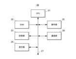
図1は、本実施の形態のランニング解析システム1を示すブロック図である。
図1に示すように、ランニング解析システム1は、測定装置10と、端末装置20と、を備えて構成される。 FIG. 1 is a block diagram showing a
As shown in FIG. 1, the
測定装置10は、ランニングのトレーニング時やレース時にユーザ(被測定者)に装着され当該トレーニング時や当該レース時の運動データ(例えば、加速度データ、角速度データ等)を採取し、当該運動データから導出されるランニング指標を記録する装置である。 The
測定装置10は、例えば、図2に示すように、付属のベルトBを有しており、ベルトBによって、ユーザの腰(仙骨)の位置で測定装置10が固定されるようになっている。なお、測定装置10は、ベルトBの代わりにクリップを有し、当該クリップによって、ユーザのランニングウェアを挟むことによって、ユーザの腰の位置で測定装置10が固定されるようにしてもよい。また、測定装置10の固定位置は、ユーザの腰の回転を測定可能な位置であればよく、上述の仙骨の位置のように筋肉や皮下脂肪等による振動の影響の少ない位置であることが好ましい。 For example, as shown in FIG. 2, the
端末装置20は、測定装置10から取得したユーザのランニング指標を表示する装置である。端末装置20としては、例えば、スマートフォンや、スマートウォッチ、スマートグラス、タブレットPC等が挙げられる。以下では、端末装置20がスマートフォンであるものとして説明を行う。 The
≪測定装置≫
次に、図3を参照して、測定装置10の機能構成を説明する。図3は、測定装置10の機能構成を示すブロック図である。≪Measuring device≫
Next, the functional configuration of the
図3に示すように、測定装置10は、CPU(Central Processing Unit)11と、RAM(Random Access Memory)12と、記憶部13と、表示部14と、操作部15と、センサ部16と、通信部17と、を備えて構成される。測定装置10の各部は、バス18を介して接続されている。 As shown in FIG. 3, the
CPU(取得手段、検出手段、衝撃指標導出手段、ノルム導出手段)11は、測定装置10の各部を制御する。CPU11は、記憶部13に記憶されているシステムプログラム及びアプリケーションプログラムのうち、指定されたプログラムを読み出してRAM12に展開し、当該プログラムとの協働で各種処理を実行する。 A CPU (acquisition means, detection means, impact index derivation means, norm derivation means) 11 controls each part of the
RAM12は、揮発性のメモリであり、各種のデータやプログラムを一時的に格納するワークエリアを形成する。 The
記憶部13は、フラッシュメモリ、EEPROM(Electrically Erasable Programmable ROM)等により構成される。記憶部13には、CPU11で実行されるシステムプログラムやアプリケーションプログラム、これらのプログラムの実行に必要なデータ等が記憶されている。また、記憶部13には、ランニングのトレーニング時やレース時に採取された運動データ及び当該運動データから導出されたランニング指標が記憶されるようになっている。 The
表示部14は、複数のLEDランプにより構成され、電源のON/OFFの状態、データの取得状態(例えばデータを取得中であるか否か)、データの送信状態(例えば、データを送信中であるか否か)や、GPS受信機163のON/OFF状態等を表示可能な表示部である。 The
操作部15は、電源のON/OFFを切り替える電源ボタン(図示省略)、データ取得の開始/終了を指示する開始/終了ボタン(図示省略)等を備えており、この操作部15からの指示に基づいて、CPU11は各部を制御するようになっている。 The
センサ部16は、加速度センサ161、角速度センサ162、GPS受信機163などを備え、測定結果をCPU11に出力する。なお、センサ部16は、図3に示されていないセンサを更に有していてもよい。 The
加速度センサ161は、互いに直交する3軸方向の加速度を検出する。そして、加速度センサ161は、検出された各軸の加速度に対応する加速度データをCPU11に出力する。 The
角速度センサ162は、互いに直交する3軸方向の角速度を検出する。そして、角速度センサ162は、検出された各軸を中心とする角速度に対応する角速度データをCPU11に出力する。 The
GPS受信機163は、測定装置10の位置情報を取得し、当該位置情報をCPU11に出力する。 The
通信部17は、ランニングのトレーニング時やレース時の運動データ及び/又は運動データから導出されたランニング指標を、CPU11による制御に基づいて端末装置20に送信するものであり、例えば、Bluetooth(登録商標)などの無線規格を採用した通信部や、USB端子などの有線式の通信部である。 The
≪端末装置≫
次に、図4を参照して、端末装置20の機能構成を説明する。図4は、端末装置20の機能構成を示すブロック図である。≪Terminal device≫
Next, the functional configuration of the
端末装置20は、CPU21と、RAM22と、記憶部23と、表示部24と、操作部25と、通信部26と、を備えて構成される。端末装置20の各部は、バス27を介して接続されている。 The
CPU21は、端末装置20の各部を制御する。CPU21は、記憶部23に記憶されているシステムプログラム及びアプリケーションプログラムのうち、指定されたプログラムを読み出してRAM22に展開し、当該プログラムとの協働で各種処理を実行する。 The
RAM22は、揮発性のメモリであり、各種のデータやプログラムを一時的に格納するワークエリアを形成する。 The
記憶部23は、例えば、フラッシュメモリ、EEPROM、HDD(Hard Disk Drive
)などにより構成される。記憶部23には、CPU21で実行されるシステムプログラムやアプリケーションプログラム、これらのプログラムの実行に必要なデータ等が記憶されている。 The
) etc. The
表示部24は、LCD(Liquid Crystal Display)、有機EL(Electro Luminescence)ディスプレイ等で構成され、CPU21から指示された表示情報に従い各種表示を行う。 The
操作部25は、端末装置20の本体部に設けられる各種の操作ボタン(図示省略)や、表示部24上に設けられるタッチセンサ(図示省略)等を有して構成され、ユーザの入力操作を受け付けて、その操作情報をCPU21に出力する。 The
通信部26は、運動データ及び/又はランニング指標を測定装置10から受信するものであり、例えば、Bluetooth(登録商標)などの無線規格を採用した通信部や、USB端子などの有線式の通信部である。 The
≪測定装置の動作≫
次に、測定装置10の動作の一環である衝撃指標導出処理について説明する。この衝撃指標導出処理は、測定装置10を装着したユーザの腰に作用する衝撃力(ストレス)を示す衝撃指標を導出する処理である。≪Operation of measuring device≫
Next, the impact index deriving process, which is part of the operation of the measuring
ここで、上記の衝撃力は、ユーザの足が地面に着いたときの衝撃(着地衝撃)に起因して発生する。具体的には、図5に示すように、ユーザの足が地面に着いたとき、足と地面との衝突が発生するために大きな衝撃が足に発生する(矢印AR1参照)。この衝撃が足首、下肢、膝、股関節と伝わり、腰への衝撃となる(矢印AR2参照)。 Here, the above-mentioned impact force is generated due to the impact when the user's foot touches the ground (landing impact). Specifically, as shown in FIG. 5, when the user's feet touch the ground, a collision between the feet and the ground causes a large impact on the feet (see arrow AR1). This impact is transmitted to the ankles, lower legs, knees, and hip joints, resulting in an impact to the lower back (see arrow AR2).
一方、ランニング動作は、腰を回転させることで足を運び、結果として体の重心を前へ進める動作である。図6は、ランニング動作時のユーザの腰の回転角度を測定した結果の一部を示すグラフである。図中の実線で示されている波形は、X軸(図2参照)を中心とする回転角度を示している。また、図中の一点鎖線で示されている波形は、Y軸(図2参照)を中心とする回転角度を示している。また、図中の二点鎖線で示されている波形は、Z軸(図2参照)を中心とする回転角度を示している。また、図中の横軸上の山型の印は、ユーザの各足の着地タイミングを示している。ユーザの腰の回転(図5の矢印AR3参照)は、本来、滑らかな連続した動きであるが、図6の丸で囲まれた箇所が示すように、各着地タイミングの直後、すなわち上記の衝撃によって、その滑らかな連続した動きが歪められてしまう。そこで、本発明は、本来の腰の回転(滑らかな連続した動き)が上記の衝撃によって歪められる成分に着目して、ユーザの腰に作用する衝撃力(ストレス)を示す衝撃指標を導出する。 On the other hand, running is a movement in which the body rotates the hips to move the feet, thereby moving the center of gravity of the body forward. FIG. 6 is a graph showing part of the results of measuring the rotation angle of the user's waist during running motion. The waveform shown by the solid line in the figure shows the rotation angle around the X-axis (see FIG. 2). Moreover, the waveform shown by the dashed line in the figure shows the rotation angle around the Y axis (see FIG. 2). Moreover, the waveform shown by the two-dot chain line in the figure shows the rotation angle around the Z axis (see FIG. 2). Further, the chevron-shaped marks on the horizontal axis in the figure indicate the landing timing of each foot of the user. The rotation of the user's hips (see arrow AR3 in Figure 5) is originally a smooth continuous movement, but as the circled area in Figure 6 shows, the rotation of the user's hips (see arrow AR3 in Figure 5) This distorts the smooth, continuous movement. Therefore, the present invention focuses on the component in which the original hip rotation (smooth continuous movement) is distorted by the above-mentioned impact, and derives an impact index indicating the impact force (stress) acting on the user's lower back.
<衝撃指標導出処理>
図7は、衝撃指標導出処理の制御手順を示すフローチャートである。なお、衝撃指標導出処理は、例えば、ランニングのトレーニングが開始される際に、上述の開始/終了ボタン(操作部15)を介して、データ取得の開始を指示する押下操作がユーザによってなされたことを契機として開始される処理である。<Impact index derivation processing>
FIG. 7 is a flowchart showing the control procedure of the impact index derivation process. Note that the impact index derivation process is performed, for example, when a user performs a press operation to instruct the start of data acquisition via the above-mentioned start/end button (operation unit 15) when running training is started. This is a process that is triggered by this.
図7に示すように、衝撃指標導出処理が開始されると、測定装置10のCPU11は、まず、加速度センサ161で検出された加速度に対応する加速度データと、角速度センサ162で検出された角速度に対応する角速度データと、を逐次取得する(ステップS1)。ここで、加速度データは、加速度センサ161で検出された加速度の値と、当該加速度が検出された検出時刻と、が対応付けられたデータとなっている。角速度データは、角速度センサ162で検出された角速度の値と、当該角速度が検出された検出時刻と、が対応付けられたデータとなっている。 As shown in FIG. 7, when the impact index derivation process is started, the
次いで、CPU11は、ステップS1で取得された加速度データ及び角速度データをセンサ座標系からワールド座標系へ変換する座標変換処理を行う(ステップS2)。ここで、ワールド座標系の座標は、図2に示すように、X軸をランニング中のユーザの左右方向、Y軸を当該ユーザの前後方向、Z軸を当該ユーザの上下方向であるものとする。また、X軸においては左手方向を正、右手方向を負とする。Y軸においては進行方向逆向きを正、進行方向を負とする。Z軸においては上方向を正、下方向を負とする。つまり、センサ座標系からワールド座標系への座標変換処理を行うことによって、地軸を基準とした座標系において加速度データ及び角速度データを扱うことが可能となる。
なお、センサ座標系からワールド座標系へのデータ変換方法は公知であるため、その説明は省略する。 Next, the
Note that the method for converting data from the sensor coordinate system to the world coordinate system is well known, so a description thereof will be omitted.
次いで、CPU11は、ステップS2で座標変換処理がなされた加速度データ及び角速度データに基づいて、ユーザの足が地面に着く着地タイミングを検出する(ステップS3)。なお、着地タイミングの検出方法については、例えば、特開2018-8015号公報において開示されており、ここではその説明は省略する。 Next, the
次いで、CPU11は、ステップS2で座標変換処理がなされた角速度データに基づいて、X軸、Y軸、Z軸の各角速度のノルムを導出する(ステップS4)。ここで、X軸、Y軸、Z軸の各角速度のノルムは、当該各角速度の二乗平均平方根により導出される。 Next, the
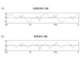
次いで、CPU11は、ステップS2で座標変換処理がなされた角速度データを時系列に並べた時系列データ、並びに、ステップS4で導出されたノルムを時系列に並べた時系列データから衝撃に対応する時系列データ(衝撃波形)をそれぞれ抽出する(ステップS5)。具体的には、CPU11は、ステップS2で座標変換処理がなされた角速度データを時系列に並べた時系列データ、並びに、ステップS4で導出されたノルムを時系列に並べた時系列データを、ランニング時の足の回転周波数を遮断するハイパスフィルタ(例えば、4Hzのハイパスフィルタ)にかけることで、衝撃に対応する時系列データ(衝撃波形(図8(b)、図9(b)、図10(b)、図11(b)参照))をそれぞれ抽出する。図8(a)は、X軸の角速度データを時系列に並べた時系列データが示す角速度波形であり、同図(b)は、X軸の衝撃に対応する時系列データが示す衝撃波形である。図9(a)は、Y軸の角速度データを時系列に並べた時系列データが示す角速度波形であり、同図(b)は、Y軸の衝撃に対応する時系列データが示す衝撃波形である。図10(a)は、Z軸の角速度データを時系列に並べた時系列データが示す角速度波形であり、同図(b)は、Z軸の衝撃に対応する時系列データが示す衝撃波形である。図11(a)は、ノルムの角速度データを時系列に並べた時系列データが示す角速度波形であり、同図(b)は、ノルムの衝撃に対応する時系列データが示す衝撃波形である。図8~図11に示す各グラフの横軸上の山型の印は、ユーザの各足の着地タイミングを示している。 Next, the
ここで、上記の衝撃に対応する時系列データ(衝撃波形)の物理的意味について説明する。
角運動方程式は、下記式で表される。
M=I・α
M:モーメント、I:慣性モーメント、α:角加速度
したがって、上記の衝撃に対応する時系列データから導出される角加速度は、ユーザの足が地面に着いたときの衝撃(着地衝撃)の伝達により腰関節で発生するモーメントに比例することとなる。つまり、腰の回転動作を妨げる外力は、腰の回転を生み出している腰関節へのストレス(衝撃力)ということができる。そこで、本実施形態では、腰関節へのストレスを分かり易くするために、平均ストレス(後述)、最大ストレス(後述)、ストレス積(後述)といった衝撃指標を、上記の衝撃に対応する時系列データから導出するようにしている。 Here, the physical meaning of the time series data (impact waveform) corresponding to the above impact will be explained.
The angular motion equation is expressed by the following formula.
M=I・α
M: moment, I: moment of inertia, α: angular acceleration Therefore, the angular acceleration derived from the time series data corresponding to the above impact is due to the transmission of the impact when the user's foot touches the ground (landing impact). It is proportional to the moment generated at the hip joint. In other words, the external force that prevents the rotation of the hips can be said to be stress (impact force) on the hip joints that cause the rotation of the hips. Therefore, in this embodiment, in order to make it easier to understand the stress on the lower back joints, impact indicators such as average stress (described later), maximum stress (described later), and stress product (described later) are used as time-series data corresponding to the above-mentioned impact. I am trying to derive it from
衝撃指標導出処理の説明に戻り、次いで、CPU11は、ステップS5で抽出された衝撃に対応する時系列データが示す各衝撃波形から着地タイミングを含む所定期間の波形を切り出す(ステップS6)。図11(b)のノルムに係る衝撃に対応する時系列データ(衝撃波形)を例に挙げて説明すると、図中の破線で囲まれた部分の波形を切り出す場合、例えば、図12に示すように、着地タイミングTの0.05s前から当該着地タイミングTの0.1s後までの期間を上記の所定期間として当該期間の波形を切り出す。 Returning to the explanation of the impact index derivation process, the
次いで、CPU11は、ステップS6で切り出された各波形においてピークを検出する(ステップS7)。上述したノルムの衝撃に対応する時系列データ(衝撃波形)から切り出された波形を例に挙げて説明すると、CPU11は、図12に示すように、ステップS6で切り出された波形において、着地タイミングTの直後に現れる極大点又は極小点をピークPとして検出する。 Next, the
次いで、CPU11は、ステップS6で切り出された各波形を対象として、図13に示すように、着地タイミングTから上記のピークPに到達するタイミングTpまでの経過時間(変化時間)t、及び、当該経過時間tにおける衝撃波形の振幅hを取得する(ステップS8)。 Next, for each waveform cut out in step S6, the
次いで、CPU11は、ステップS6で切り出された各波形を対象として、衝撃指標(平均ストレス、最大ストレス、ストレス積)を導出する(ステップS9)。 Next, the
具体的には、上述したノルムの衝撃に対応する時系列データ(衝撃波形)から切り出された波形(図13参照)を例に挙げて説明すると、CPU11は、着地タイミングTからピークPに到達するタイミングTpまでの経過時間tにおける波形の振幅hを当該経過時間tで除した値を、平均ストレスとして導出する。また、CPU11は、着地タイミングTからピークPに到達するタイミングTpまでの経過時間tにおける波形の接線の傾きが最大となる点での当該接線の傾きを示す最大斜度を、最大ストレスとして導出する。また、CPU11は、着地タイミングTからピークPに到達するタイミングTpまでの経過時間tにおける波形の振幅hを、ストレス積として導出する。 Specifically, to explain the waveform extracted from the time series data (impact waveform) corresponding to the norm impact mentioned above (see FIG. 13) as an example, the
次いで、CPU11は、ステップS9で導出された衝撃指標(平均ストレス、最大ストレス、ストレス積)を、通信部17を介して端末装置20に送信する(ステップS10)。これにより、端末装置20では、測定装置10より受信した衝撃指標を、表示部24に表示可能となる。 Next, the
次いで、CPU11は、上述の開始/終了ボタン(操作部15)を介して、データ取得の終了を指示する押下操作がユーザによってなされたか否かを判定する(ステップS11)。 Next, the
ステップS11において、開始/終了ボタン(操作部15)を介して、データ取得の終了を指示する押下操作がユーザによってなされていないと判定された場合(ステップS11;NO)、CPU11は、処理をステップS1へ戻し、それ以降の処理を繰り返し行う。 In step S11, if it is determined that the user has not pressed the start/end button (operation unit 15) to instruct the end of data acquisition (step S11; NO), the
また、ステップS11において、開始/終了ボタン(操作部15)を介して、データ取得の終了を指示する押下操作がユーザによってなされたと判定された場合(ステップS11;YES)、CPU11は、ステップS9で導出された衝撃指標に係る衝撃指標データを記憶部13に記憶する(ステップS12)。そして、CPU11は、衝撃指標導出処理を終了する。なお、ステップS12では、衝撃指標データに加えて、ステップS1で逐次取得された加速度データ及び角速度データを記憶部13に記憶するようにしてもよい。 Further, in step S11, if it is determined that the user has performed a press operation to instruct the end of data acquisition via the start/end button (operation unit 15) (step S11; YES), the
以上のように、本実施形態の測定装置10は、ランニング期間中(運動期間中)に角速度センサ162で検出された角速度に係る角速度データ(角速度情報)に基づいて導出される衝撃に対応する時系列データ(衝撃波形)を取得し、取得された衝撃に対応する時系列データからユーザ(被測定者)の着地タイミングの直後に現れるピークPを検出し、ユーザの着地タイミングTからピークPに到達するタイミングTpまでの衝撃に対応する時系列データに基づいて、ユーザに作用する衝撃力を示す衝撃指標を導出する。
したがって、測定装置10によれば、ユーザの着地タイミングTからピークPに到達するタイミングTpまでの衝撃に対応する時系列データに基づいて、ユーザに作用する衝撃力を示す衝撃指標を導出するので、当該衝撃指標を精度良く導出することができる。
この結果、測定装置10により導出される衝撃指標を、ユーザの身体の故障の可能性を判断する際や、ランニングフォーム改善の方向性を検討する際に活用することができる。また、ランニングフォーム改善の結果を検証する際にも活用することができる。 As described above, the measuring
Therefore, according to the measuring
As a result, the impact index derived by the measuring
また、本実施形態の測定装置10は、互いに直交する3軸方向(X軸、Y軸、Z軸)のそれぞれを対象として衝撃に対応する時系列データを取得する。 したがって、測定装置10によれば、角速度センサ162によって角速度が検出される3軸方向のそれぞれについて衝撃指標を導出することができるので、当該衝撃指標によって、ユーザのどの方向にどれ位のストレスが加わっているのかを当該ユーザに把握させることができる。 Furthermore, the measuring
また、本実施形態の測定装置10は、角速度センサ162で検出された3軸方向の角速度に係る角速度情報に基づいて、当該3軸方向の角速度のノルムを導出し、導出されたノルムに基づいて導出される衝撃に対応する時系列データを取得する。
したがって、測定装置10によれば、3軸方向の角速度のノルムについても衝撃指標を導出することができるので、ランニング時のようにユーザの身体の回転軸が変化し易い場合であっても、当該身体の回転方向に対する衝撃指標を適切に導出することができる。 Furthermore, the measuring
Therefore, according to the measuring
また、本実施形態の測定装置10は、衝撃指標として、平均ストレス、最大ストレス、ストレス積のそれぞれを導出するので、ユーザの身体の故障の可能性を判断する際や、ランニングフォーム改善の方向性を検討する際、ランニングフォーム改善の結果を検証する際に、これらの衝撃指標を有効に活用することができる。 Furthermore, since the measuring
また、本実施形態の測定装置10は、角速度センサ162がユーザの腰部に装着されるようになっており、当該ユーザの腰部に作用する衝撃力を示す衝撃指標を導出する。
したがって、測定装置10によれば、ユーザの腰部に作用する衝撃力を示す衝撃指標を精度良く導出することができる。 Furthermore, in the measuring
Therefore, according to the measuring
以上、本発明を実施形態に基づいて具体的に説明してきたが、本発明は上記実施形態に限定されるものではなく、その要旨を逸脱しない範囲で変更可能である。
例えば、上記実施形態では、測定装置10の表示部14は、複数のLEDランプにより構成されているが、LCDディスプレイ等で構成し、自装置で検出した運動データ及び導出されたランニング指標や衝撃指標を当該表示部14に表示させるようにしてもよい。 Although the present invention has been specifically explained based on the embodiments above, the present invention is not limited to the above embodiments, and can be modified without departing from the gist thereof.
For example, in the above embodiment, the
また、上記実施形態では、測定装置10が衝撃指標を導出し、導出された衝撃指標を端末装置20に送信するようにしているが、例えば、測定装置10によって逐次取得される加速度データ及び角速度データを、当該測定装置10が端末装置20に送信し、端末装置20が、当該加速度データ及び当該角速度データに基づいて、衝撃指標を導出するようにしてもよい。 Further, in the above embodiment, the measuring
また、上記実施形態では、X軸、Y軸、Z軸の角速度データを時系列に並べた時系列データから抽出される衝撃に対応する時系列データ(衝撃波形)に基づいて、各軸の衝撃指標を導出するとともに、X軸、Y軸、Z軸の各角速度のノルムの角速度データを時系列に並べた時系列データから抽出される衝撃に対応する時系列データ(衝撃波形)に基づいて、当該ノルムの衝撃指標を導出しているが、例えば、X軸、Y軸、Z軸の各角速度をクォータニオンに変換することで衝撃指標を導出するようにしてもよい。 In addition, in the above embodiment, the impact of each axis is calculated based on the time series data (shock waveform) corresponding to the impact extracted from the time series data in which the angular velocity data of the X, Y, and Z axes are arranged in time series. In addition to deriving the index, based on the time series data (shock waveform) corresponding to the shock extracted from the time series data in which the angular velocity data of the norm of each angular velocity of the X axis, Y axis, and Z axis is arranged in time series, Although the impact index of the norm is derived, for example, the impact index may be derived by converting the angular velocities of the X, Y, and Z axes into quaternions.
また、上記実施形態では、例えば、ユーザの腰の形状、質量、腰関節の位置等の情報を入力できるユーザインタフェースを測定装置10が備え、当該情報に基づいて、測定装置10が当該ユーザの腰関節周りの慣性モーメントを導出できるようにしてもよい。これにより、導出された慣性モーメントと、X軸、Y軸、Z軸の角速度データを時系列に並べた時系列データから抽出される衝撃に対応する時系列データ(衝撃波形)等より導出される角加速度と、に基づいて、実際のモーメントを導出することが可能となる。更に、上記のユーザインタフェースを介して、ユーザの股関節の位置に係る情報が入力された場合、当該股関節で発生するモーメントも導出することが可能となる。
なお、腰の形状、質量、腰関節の位置等が正確に分からない場合には、上記のユーザインタフェースを介して、ユーザの身長と体重の情報を入力させ、当該情報を所定の身体モデルに当てはめることで、ユーザの腰関節の位置や、当該腰関節周りの慣性モーメント等を推定し、実際のモーメントを導出できるようにしてもよい。 Further, in the above embodiment, the measuring
In addition, if the shape, mass, position of the hip joints, etc. of the waist are not accurately known, the user can input information on the user's height and weight via the above user interface, and apply the information to a predetermined body model. In this way, the position of the user's waist joint, the moment of inertia around the waist joint, etc. may be estimated, and the actual moment may be derived.
また、上記実施形態では、運動の一例としてランニングを挙げているが、当該運動は、歩行や走行を伴うものであればよく、例えば、ウォーキングや競歩などでもよい。 Further, in the above embodiment, running is cited as an example of exercise, but the exercise may be any exercise that involves walking or running, such as walking or race walking.
また、上記実施形態では、測定装置10をユーザの腰(仙骨)の位置に固定することで、当該ユーザの腰に作用する衝撃力を示す衝撃指標を導出するようにしているが、当該測定装置10をユーザの他の部位(例えば、腹部、胸部、脚部(大腿部)など)に固定し、当該他の部位に作用する衝撃力を示す衝撃指標を導出するようにしてもよい。 Furthermore, in the above embodiment, the measuring
また、上記実施形態では、測定装置10は、その本体内にセンサ部16を有しているが、センサ部16を、当該本体から分離した別装置として設けるようにしてもよい。かかる場合、衝撃指標を導出する対象の部位にセンサ部16を有する上記の別装置を固定するようにする。 Further, in the above embodiment, the measuring
以上、本発明の実施形態を説明したが、本発明の範囲は、上述の実施の形態に限定するものではなく、特許請求の範囲に記載された発明の範囲をその均等の範囲を含む。
以下に、この出願の願書に最初に添付した特許請求の範囲に記載した発明を付記する。付記に記載した請求項の項番は、この出願の願書に最初に添付した特許請求の範囲のとおりである。 Although the embodiments of the present invention have been described above, the scope of the present invention is not limited to the above-described embodiments, and includes the scope of the invention described in the claims and its equivalent range.
Below, the invention described in the claims first attached to the application of this application will be added. The claim numbers stated in the supplementary notes are as in the claims originally attached to the request for this application.
〔付記〕
<請求項1>
被測定者の運動に係る指標を導出する運動指標導出装置であって、
運動期間中に角速度センサで検出された角速度に係る角速度情報に基づいて導出される衝撃に対応する時系列データを取得する取得手段と、
前記取得手段により取得された前記衝撃に対応する時系列データから前記被測定者の着地タイミングの直後に現れるピークを検出する検出手段と、
前記被測定者の着地タイミングから前記ピークに到達するタイミングまでの前記衝撃に対応する時系列データに基づいて、前記被測定者に作用する衝撃力を示す衝撃指標を導出する衝撃指標導出手段と、
を備えることを特徴とする運動指標導出装置。
<請求項2>
前記角速度センサは、互いに直交する3軸方向の角速度を検出する3軸角速度センサであり、
前記取得手段は、前記3軸方向のそれぞれを対象として前記衝撃に対応する時系列データを取得する、
ことを特徴とする請求項1に記載の運動指標導出装置。
<請求項3>
前記3軸角速度センサで検出された前記3軸方向の角速度に係る角速度情報に基づいて、前記3軸方向の角速度のノルムを導出するノルム導出手段を備え、
前記取得手段は、更に、前記ノルム導出手段により導出された前記ノルムに基づいて導出される前記衝撃に対応する時系列データを取得する、
ことを特徴とする請求項2に記載の運動指標導出装置。
<請求項4>
前記衝撃指標導出手段により導出された前記衝撃指標を表示部に表示させる表示制御手段を備える、
ことを特徴とする請求項1に記載の運動指標導出装置。
<請求項5>
前記取得手段は、前記衝撃に対応する時系列データとして、前記角速度情報が示す角速度波形から抽出される衝撃波形を取得する、
ことを特徴とする請求項1に記載の運動指標導出装置。
<請求項6>
前記角速度センサは、前記被測定者の腰部に装着され、
前記衝撃指標導出手段は、前記被測定者の腰部に作用する衝撃力を示す衝撃指標を導出する、
ことを特徴とする請求項1に記載の運動指標導出装置。
<請求項7>
前記衝撃指標は、平均ストレスに係る指標を含み、
前記衝撃指標導出手段は、前記衝撃に対応する時系列データに基づいて、当該衝撃に対応する時系列データが示す衝撃波形の振幅を、前記被測定者の着地タイミングから前記ピークに到達するタイミングまでの経過時間で除した値を、前記平均ストレスとして導出する、
ことを特徴とする請求項1~6のいずれか一項に記載の運動指標導出装置。
<請求項8>
前記衝撃指標は、最大ストレスに係る指標を含み、
前記衝撃指標導出手段は、前記衝撃に対応する時系列データに基づいて、前記被測定者の着地タイミングから前記ピークに到達するタイミングまでの経過時間における当該衝撃に対応する時系列データが示す衝撃波形の接線の傾きが最大となる点での当該接線の傾きを示す最大斜度を、前記最大ストレスとして導出する、
ことを特徴とする請求項1~6のいずれか一項に記載の運動指標導出装置。
<請求項9>
前記衝撃指標は、ストレス積に係る指標を含み、
前記衝撃指標導出手段は、前記衝撃に対応する時系列データに基づいて、前記被測定者の着地タイミングから前記ピークに到達するタイミングまでの経過時間における当該衝撃に対応する時系列データが示す衝撃波形の振幅を、前記ストレス積として導出する、
ことを特徴とする請求項1~6のいずれか一項に記載の運動指標導出装置。
<請求項10>
被測定者の運動に係る指標を導出する運動指標導出方法であって、
運動期間中に角速度センサで検出された角速度に係る角速度情報に基づいて導出される衝撃に対応する時系列データを取得する取得工程と、
前記取得工程により取得された前記衝撃に対応する時系列データから前記被測定者の着地タイミングの直後に現れるピークを検出する検出工程と、
前記被測定者の着地タイミングから前記ピークに到達するタイミングまでの前記衝撃に対応する時系列データに基づいて、前記被測定者に作用する衝撃力を示す衝撃指標を導出する衝撃指標導出工程と、
を含むことを特徴とする運動指標導出方法。
<請求項11>
被測定者の運動に係る指標を導出する運動指標導出装置のコンピュータを、
運動期間中に角速度センサで検出された角速度に係る角速度情報に基づいて導出される衝撃に対応する時系列データを取得する取得手段、
前記取得手段により取得された前記衝撃に対応する時系列データから前記被測定者の着地タイミングの直後に現れるピークを検出する検出手段、
前記被測定者の着地タイミングから前記ピークに到達するタイミングまでの前記衝撃に対応する時系列データに基づいて、前記被測定者に作用する衝撃力を示す衝撃指標を導出する衝撃指標導出手段、
として機能させることを特徴とする運動指標導出プログラム。[Additional notes]
<Claim 1>
A movement index deriving device for deriving an index related to the movement of a person to be measured,
acquisition means for acquiring time-series data corresponding to an impact derived based on angular velocity information related to the angular velocity detected by the angular velocity sensor during the exercise period;
detection means for detecting a peak that appears immediately after the landing timing of the subject from the time series data corresponding to the impact acquired by the acquisition means;
Impact index deriving means for deriving an impact index indicating an impact force acting on the subject based on time series data corresponding to the impact from the timing at which the subject lands to the timing at which the peak is reached;
An exercise index deriving device comprising:
<Claim 2>
The angular velocity sensor is a three-axis angular velocity sensor that detects angular velocity in three axes directions orthogonal to each other,
The acquisition means acquires time series data corresponding to the impact in each of the three axial directions.
The exercise index deriving device according to
<Claim 3>
Norm deriving means for deriving a norm of the angular velocity in the three-axis directions based on angular velocity information related to the angular velocity in the three-axis directions detected by the three-axis angular velocity sensor,
The acquisition means further acquires time series data corresponding to the shock derived based on the norm derived by the norm derivation means.
The exercise index deriving device according to
<Claim 4>
comprising display control means for displaying the impact index derived by the impact index deriving means on a display section;
The exercise index deriving device according to
<Claim 5>
The acquisition means acquires an impact waveform extracted from an angular velocity waveform indicated by the angular velocity information as time series data corresponding to the impact.
The exercise index deriving device according to
<Claim 6>
The angular velocity sensor is attached to the waist of the subject,
The impact index deriving means derives an impact index indicating an impact force acting on the waist of the subject.
The exercise index deriving device according to
<Claim 7>
The impact index includes an index related to average stress,
The impact index deriving means calculates, based on the time-series data corresponding to the impact, the amplitude of the impact waveform indicated by the time-series data corresponding to the impact, from the time when the subject lands to the time when the peak is reached. Derive the value divided by the elapsed time as the average stress,
The movement index deriving device according to any one of
<Claim 8>
The impact index includes an index related to maximum stress,
The impact index deriving means is configured to calculate, based on the time series data corresponding to the impact, a shock waveform indicated by the time series data corresponding to the impact in the elapsed time from the landing timing of the subject to the timing of reaching the peak. Deriving the maximum slope indicating the slope of the tangent line at the point where the slope of the tangent line is the maximum as the maximum stress,
The movement index deriving device according to any one of
<Claim 9>
The impact index includes an index related to stress product,
The impact index deriving means is configured to calculate, based on the time series data corresponding to the impact, a shock waveform indicated by the time series data corresponding to the impact in the elapsed time from the landing timing of the subject to the timing of reaching the peak. Deriving the amplitude of as the stress product,
The movement index deriving device according to any one of
<Claim 10>
A movement index derivation method for deriving an index related to the movement of a subject, the method comprising:
an acquisition step of acquiring time series data corresponding to an impact derived based on angular velocity information related to the angular velocity detected by the angular velocity sensor during the exercise period;
a detection step of detecting a peak that appears immediately after the landing timing of the subject from the time series data corresponding to the impact acquired in the acquisition step;
an impact index deriving step of deriving an impact index indicating an impact force acting on the subject based on time-series data corresponding to the impact from the timing of landing of the subject to the timing of reaching the peak;
A method for deriving an exercise index, the method comprising:
<Claim 11>
The computer of the movement index derivation device that derives the index related to the movement of the subject,
acquisition means for acquiring time-series data corresponding to an impact derived based on angular velocity information related to angular velocity detected by an angular velocity sensor during an exercise period;
detection means for detecting a peak that appears immediately after the landing timing of the subject from the time series data corresponding to the impact acquired by the acquisition means;
Impact index deriving means for deriving an impact index indicating an impact force acting on the subject based on time series data corresponding to the impact from the timing when the subject lands to the timing when the peak is reached;
An exercise index derivation program characterized by functioning as a.
1 ランニング解析システム
10 測定装置
11 CPU
12 RAM
13 記憶部
14 表示部
15 操作部
16 センサ部
161 加速度センサ
162 角速度センサ
163 GPS受信機
17 通信部
20 端末装置
21 CPU
22 RAM
23 記憶部
24 表示部
25 操作部
26 通信部1 Running
12 RAM
13
22 RAM
23
Claims (11)
Translated fromJapanese運動期間中に角速度センサで検出された角速度に係る角速度情報に基づいて導出される衝撃に対応する時系列データを取得する取得手段と、
前記取得手段により取得された前記衝撃に対応する時系列データから前記被測定者の着地タイミングの直後に現れるピークを検出する検出手段と、
前記被測定者の着地タイミングから前記ピークに到達するタイミングまでの前記衝撃に対応する時系列データに基づいて、前記被測定者に作用する衝撃力を示す衝撃指標を導出する衝撃指標導出手段と、
を備えることを特徴とする運動指標導出装置。 A movement index deriving device for deriving an index related to the movement of a person to be measured,
acquisition means for acquiring time-series data corresponding to an impact derived based on angular velocity information related to the angular velocity detected by the angular velocity sensor during the exercise period;
detection means for detecting a peak that appears immediately after the landing timing of the subject from the time series data corresponding to the impact acquired by the acquisition means;
Impact index deriving means for deriving an impact index indicating an impact force acting on the subject based on time series data corresponding to the impact from the timing at which the subject lands to the timing at which the peak is reached;
An exercise index deriving device comprising:
前記取得手段は、前記3軸方向のそれぞれを対象として前記衝撃に対応する時系列データを取得する、
ことを特徴とする請求項1に記載の運動指標導出装置。 The angular velocity sensor is a three-axis angular velocity sensor that detects angular velocity in three axes directions orthogonal to each other,
The acquisition means acquires time series data corresponding to the impact in each of the three axial directions.
The exercise index deriving device according to claim 1, characterized in that:
前記取得手段は、更に、前記ノルム導出手段により導出された前記ノルムに基づいて導出される前記衝撃に対応する時系列データを取得する、
ことを特徴とする請求項2に記載の運動指標導出装置。 Norm deriving means for deriving a norm of the angular velocity in the three-axis directions based on angular velocity information related to the angular velocity in the three-axis directions detected by the three-axis angular velocity sensor,
The acquisition means further acquires time series data corresponding to the shock derived based on the norm derived by the norm derivation means.
The exercise index deriving device according to claim 2, characterized in that:
ことを特徴とする請求項1に記載の運動指標導出装置。 comprising display control means for displaying the impact index derived by the impact index deriving means on a display section;
The exercise index deriving device according to claim 1, characterized in that:
ことを特徴とする請求項1に記載の運動指標導出装置。 The acquisition means acquires an impact waveform extracted from an angular velocity waveform indicated by the angular velocity information as time series data corresponding to the impact.
The exercise index deriving device according to claim 1, characterized in that:
前記衝撃指標導出手段は、前記被測定者の腰部に作用する衝撃力を示す衝撃指標を導出する、
ことを特徴とする請求項1に記載の運動指標導出装置。 The angular velocity sensor is attached to the waist of the subject,
The impact index deriving means derives an impact index indicating an impact force acting on the waist of the subject.
The exercise index deriving device according to claim 1, characterized in that:
前記衝撃指標導出手段は、前記衝撃に対応する時系列データに基づいて、当該衝撃に対応する時系列データが示す衝撃波形の振幅を、前記被測定者の着地タイミングから前記ピークに到達するタイミングまでの経過時間で除した値を、前記平均ストレスとして導出する、
ことを特徴とする請求項1~6のいずれか一項に記載の運動指標導出装置。 The impact index includes an index related to average stress,
The impact index deriving means calculates, based on the time-series data corresponding to the impact, the amplitude of the impact waveform indicated by the time-series data corresponding to the impact, from the time when the subject lands to the time when the peak is reached. Derive the value divided by the elapsed time as the average stress,
The movement index deriving device according to any one of claims 1 to 6.
前記衝撃指標導出手段は、前記衝撃に対応する時系列データに基づいて、前記被測定者の着地タイミングから前記ピークに到達するタイミングまでの経過時間における当該衝撃に対応する時系列データが示す衝撃波形の接線の傾きが最大となる点での当該接線の傾きを示す最大斜度を、前記最大ストレスとして導出する、
ことを特徴とする請求項1~6のいずれか一項に記載の運動指標導出装置。 The impact index includes an index related to maximum stress,
The impact index deriving means is configured to calculate, based on the time series data corresponding to the impact, a shock waveform indicated by the time series data corresponding to the impact in the elapsed time from the landing timing of the subject to the timing of reaching the peak. Deriving the maximum slope indicating the slope of the tangent line at the point where the slope of the tangent line is the maximum as the maximum stress,
The movement index deriving device according to any one of claims 1 to 6.
前記衝撃指標導出手段は、前記衝撃に対応する時系列データに基づいて、前記被測定者の着地タイミングから前記ピークに到達するタイミングまでの経過時間における当該衝撃に対応する時系列データが示す衝撃波形の振幅を、前記ストレス積として導出する、
ことを特徴とする請求項1~6のいずれか一項に記載の運動指標導出装置。 The impact index includes an index related to stress product,
The impact index deriving means is configured to calculate, based on the time series data corresponding to the impact, a shock waveform indicated by the time series data corresponding to the impact in the elapsed time from the landing timing of the subject to the timing of reaching the peak. Deriving the amplitude of as the stress product,
The movement index deriving device according to any one of claims 1 to 6.
運動期間中に角速度センサで検出された角速度に係る角速度情報に基づいて導出される衝撃に対応する時系列データを取得する取得工程と、
前記取得工程により取得された前記衝撃に対応する時系列データから前記被測定者の着地タイミングの直後に現れるピークを検出する検出工程と、
前記被測定者の着地タイミングから前記ピークに到達するタイミングまでの前記衝撃に対応する時系列データに基づいて、前記被測定者に作用する衝撃力を示す衝撃指標を導出する衝撃指標導出工程と、
を含むことを特徴とする運動指標導出方法。 A movement index derivation method for deriving an index related to the movement of a subject, the method comprising:
an acquisition step of acquiring time series data corresponding to an impact derived based on angular velocity information related to the angular velocity detected by the angular velocity sensor during the exercise period;
a detection step of detecting a peak that appears immediately after the landing timing of the subject from the time series data corresponding to the impact acquired in the acquisition step;
an impact index deriving step of deriving an impact index indicating an impact force acting on the subject based on time-series data corresponding to the impact from the timing when the subject lands to the timing when the peak is reached;
A method for deriving an exercise index, the method comprising:
運動期間中に角速度センサで検出された角速度に係る角速度情報に基づいて導出される衝撃に対応する時系列データを取得する取得手段、
前記取得手段により取得された前記衝撃に対応する時系列データから前記被測定者の着地タイミングの直後に現れるピークを検出する検出手段、
前記被測定者の着地タイミングから前記ピークに到達するタイミングまでの前記衝撃に対応する時系列データに基づいて、前記被測定者に作用する衝撃力を示す衝撃指標を導出する衝撃指標導出手段、
として機能させることを特徴とする運動指標導出プログラム。 The computer of the movement index derivation device that derives the index related to the movement of the subject,
acquisition means for acquiring time-series data corresponding to an impact derived based on angular velocity information related to angular velocity detected by an angular velocity sensor during an exercise period;
detection means for detecting a peak that appears immediately after the landing timing of the subject from the time series data corresponding to the impact acquired by the acquisition means;
Impact index deriving means for deriving an impact index indicating an impact force acting on the subject based on time series data corresponding to the impact from the timing when the subject lands to the timing when the peak is reached;
An exercise index derivation program characterized by functioning as a.
Priority Applications (1)
| Application Number | Priority Date | Filing Date | Title |
|---|---|---|---|
| JP2022138909AJP2024034572A (en) | 2022-09-01 | 2022-09-01 | Exercise index derivation device, exercise index derivation method, and exercise index derivation program |
Applications Claiming Priority (1)
| Application Number | Priority Date | Filing Date | Title |
|---|---|---|---|
| JP2022138909AJP2024034572A (en) | 2022-09-01 | 2022-09-01 | Exercise index derivation device, exercise index derivation method, and exercise index derivation program |
Publications (1)
| Publication Number | Publication Date |
|---|---|
| JP2024034572Atrue JP2024034572A (en) | 2024-03-13 |
Family
ID=90194453
Family Applications (1)
| Application Number | Title | Priority Date | Filing Date |
|---|---|---|---|
| JP2022138909APendingJP2024034572A (en) | 2022-09-01 | 2022-09-01 | Exercise index derivation device, exercise index derivation method, and exercise index derivation program |
Country Status (1)
| Country | Link |
|---|---|
| JP (1) | JP2024034572A (en) |
- 2022
- 2022-09-01JPJP2022138909Apatent/JP2024034572A/enactivePending
Similar Documents
| Publication | Publication Date | Title |
|---|---|---|
| JP4962765B2 (en) | Walking analysis device and walking analysis method | |
| JP4915263B2 (en) | Motor function improvement menu proposal system from walking ability and motor function improvement menu proposal method from walking ability | |
| JP5756230B2 (en) | Training equipment | |
| EP3057505B1 (en) | Method and apparatus for assessing the performances of an athlete that performs a gymnastic exercise | |
| JP2009261595A (en) | System for analyzing walking and proposing exercise menu | |
| Varela et al. | A kinematic characterization of human walking by using CaTraSys | |
| JP2008173365A (en) | Gait analysis system | |
| US20170151463A1 (en) | Method and apparatus for optimizing running performance of an individual | |
| CN108338790A (en) | Gait analysis and tumble assessment system | |
| JP6259301B2 (en) | Moving motion analysis apparatus, method and system, and program | |
| JP2017148287A (en) | Stumble risk assessment method | |
| JP2019195633A (en) | Ivlr prediction method and risk quantification device for injury during running exercise using the same | |
| JP2024034572A (en) | Exercise index derivation device, exercise index derivation method, and exercise index derivation program | |
| JP2017176244A (en) | Dynamic balance evaluation device | |
| JP6378492B2 (en) | Moving motion analysis apparatus and program | |
| JP2006087735A (en) | Gait analyzer | |
| EP4302627A1 (en) | Body condition estimation system and shoe | |
| CN113303764B (en) | System for detecting muscle health state of object of interest | |
| EP2889853A1 (en) | A method for optimizing running performance for an individual | |
| CN113303765B (en) | System for detecting specific kind muscle problem of interested object | |
| JP6552875B2 (en) | Moving motion analysis apparatus, method and program | |
| JP6378491B2 (en) | Moving motion analysis apparatus, method and system, and program | |
| JP2016032525A (en) | Exercise ability evaluation method, exercise ability evaluation apparatus, exercise ability evaluation system, and program | |
| JP6486200B2 (en) | Mobile motion analysis apparatus, system, and program | |
| JP7521562B2 (en) | Information processing device, running index derivation method and program |
Legal Events
| Date | Code | Title | Description |
|---|---|---|---|
| A621 | Written request for application examination | Free format text:JAPANESE INTERMEDIATE CODE: A621 Effective date:20250716 |