Movatterモバイル変換


[0]ホーム

URL:


JP2024034493A - Moisture absorption cartridge and automobile air conditioner using the same - Google Patents

Moisture absorption cartridge and automobile air conditioner using the same
Download PDF

Info

Publication number
JP2024034493A
JP2024034493AJP2022138751AJP2022138751AJP2024034493AJP 2024034493 AJP2024034493 AJP 2024034493AJP 2022138751 AJP2022138751 AJP 2022138751AJP 2022138751 AJP2022138751 AJP 2022138751AJP 2024034493 AJP2024034493 AJP 2024034493A
Authority
JP
Japan
Prior art keywords
air
moisture absorption
path
desiccant
heat exchange
Prior art date
Legal status (The legal status is an assumption and is not a legal conclusion. Google has not performed a legal analysis and makes no representation as to the accuracy of the status listed.)
Pending
Application number
JP2022138751A
Other languages
Japanese (ja)
Inventor
悠太 菊地
Yuta Kikuchi
Current Assignee (The listed assignees may be inaccurate. Google has not performed a legal analysis and makes no representation or warranty as to the accuracy of the list.)
Sumitomo Chemical Co Ltd
Original Assignee
Sumitomo Chemical Co Ltd
Priority date (The priority date is an assumption and is not a legal conclusion. Google has not performed a legal analysis and makes no representation as to the accuracy of the date listed.)
Filing date
Publication date
Application filed by Sumitomo Chemical Co LtdfiledCriticalSumitomo Chemical Co Ltd
Priority to JP2022138751ApriorityCriticalpatent/JP2024034493A/en
Publication of JP2024034493ApublicationCriticalpatent/JP2024034493A/en
Pendinglegal-statusCriticalCurrent

Links

Images

Landscapes

Abstract

Translated fromJapanese

【課題】自動車の空調装置におけるエバポレーターの消費電力を低減できる小型の吸湿部材を提供することを目的とする。【解決手段】デシカント収容容器と、吸湿域と、吸湿した水分の脱着域とを備え、かつ前記容器に収容されたデシカントと、容器内に取り込まれた空気を、前記吸湿域を通って容器外に排出する除湿経路と、前記脱着域を通り、かつ容器内で循環する空気循環路と、ヒーターとを有し、前記空気循環路が、前記ヒーターと、前記除湿経路との熱交換部と、この熱交換によって生じる水の排出口とを空気循環路に沿ってこの順で備える吸湿カートリッジ。【選択図】図2An object of the present invention is to provide a compact moisture absorbing member that can reduce the power consumption of an evaporator in an automobile air conditioner. [Solution] A desiccant storage container, a moisture absorption region, and a desorption region for absorbing moisture are provided, and the desiccant contained in the container and the air taken into the container are passed through the moisture absorption region to the outside of the container. an air circulation path that passes through the desorption area and circulates within the container; and a heater, the air circulation path having a heat exchange section between the heater and the dehumidification path; The moisture absorption cartridge is provided with a discharge port for water produced by this heat exchange in this order along an air circulation path. [Selection diagram] Figure 2

Description

Translated fromJapanese

本発明は、吸湿カートリッジ及びこれを用いた自動車の空調装置に関する。 TECHNICAL FIELD The present invention relates to a moisture absorption cartridge and an automobile air conditioner using the same.

車室内では、雨天時の湿気や車内の人の呼気による湿気などによって、湿度が高くなることがあり、快適な車内環境の維持や、窓ガラスの曇り発生防止のため、空調装置による車室内の除湿が必要な場合がある。 Humidity inside a vehicle can become high due to humidity during rainy weather or moisture from the breath of people inside the vehicle.In order to maintain a comfortable interior environment and prevent the windows from fogging up, the air conditioner must be Dehumidification may be required.

図1にエバポレーターを用いた従来の空調装置1を示す。空調装置1は、空気の流入口11A及び11Bと、流入した空気を冷却して飽和水蒸気量を低下させることにより除湿するためのエバポレーター13と、冷却された空気を必要に応じて暖めるためのヒーター14と、除湿されかつ必要に応じて暖められた気体を車内に供給するための車内側吹出口16を備えている。前記空気流入口11Aまたは11Bでは、内外気切替ドア11により車外空気流入口11Aからの外気または車内空気流入口11Bからの内気を切り替えて取り込み、取り込まれた外気または内気が送風機12によってエバポレーター13に運ばれる。ヒーター14はエバポレーター13の下流側に備えられており、エアミックスドア15の切替位置に応じて、エバポレーター13を通過した空気が、ヒーター14を通過することなく(冷房時)、又はヒーター14を通過して(暖房時)、車内側吹出口16を通して車内に導入される。車内側吹出口16は、より具体的には、フロントガラス17側から順に、デフロスタ(DEF)吹出口16A、フェイス(FACE)吹出口16B、フット(FOOT)吹出口16Cが形成されており、吹出口は適宜選択できる。 FIG. 1 shows aconventional air conditioner 1 using an evaporator. Theair conditioner 1 includesair inlets 11A and 11B, anevaporator 13 for cooling the incoming air and dehumidifying it by lowering the amount of saturated water vapor, and a heater for warming the cooled air as necessary. 14, and a vehicleinterior air outlet 16 for supplying dehumidified and, if necessary, warmed gas into the vehicle interior. At theair inlet 11A or 11B, the outside air from theoutside air inlet 11A or the inside air from theinside air inlet 11B is switched and taken in by the inside/outsideair switching door 11, and the taken outside air or inside air is sent to theevaporator 13 by theblower 12. carried. Theheater 14 is provided downstream of theevaporator 13, and depending on the switching position of theair mix door 15, the air that has passed through theevaporator 13 either does not pass through the heater 14 (during cooling) or passes through theheater 14. (during heating), and is introduced into the vehicle through theinterior air outlet 16. More specifically, the vehicleinterior air outlet 16 includes, in order from thewindshield 17 side, a defroster (DEF)air outlet 16A, a face (FACE)air outlet 16B, and a foot (FOOT)air outlet 16C. The exit can be selected as appropriate.

しかし、エバポレーター13を用いて湿度を低下させるためには、大きなエネルギーを要する。自動車空調システムの稼働に大きなエネルギーが消費されると、燃費が悪化するため望ましくなく、エバポレーターの消費電力量を抑えることが重要である。 However, reducing the humidity using theevaporator 13 requires a large amount of energy. If a large amount of energy is consumed to operate an automobile air conditioning system, it is undesirable because fuel efficiency deteriorates, so it is important to reduce the amount of power consumed by the evaporator.

例えば、特許文献1では、自動車空調システムにおけるエバポレーターの上流側に、回転可能に配置された吸湿ローターと、吸湿ローターの再生用ヒーターが配置され、吸湿ローターで湿度を低下させた空気がエバポレーターへと運ばれている。 For example, inPatent Document 1, a moisture absorption rotor rotatably arranged and a heater for regenerating the moisture absorption rotor are arranged upstream of an evaporator in an automobile air conditioning system, and air whose humidity has been lowered by the moisture absorption rotor is sent to the evaporator. being carried.

特開2006-248359号公報Japanese Patent Application Publication No. 2006-248359

上記した特許文献1の技術では、吸湿ローターによって湿度を低減した空気がエバポレーターに運ばれるため、エバポレーターでの除湿量を低減することができる。しかし、特許文献1では、吸湿ローターを加熱して再生した後の湿気を多く含んだ空気は車外に排出されており、この車外排出用のダクトが必要であるため、小型化することが難しい。 In the technique ofPatent Document 1 described above, since air with reduced humidity is conveyed to the evaporator by the moisture absorption rotor, the amount of dehumidification in the evaporator can be reduced. However, inPatent Document 1, air containing a large amount of moisture after heating and regenerating the moisture absorption rotor is discharged to the outside of the vehicle, and a duct for discharging this to the outside of the vehicle is required, making it difficult to downsize.

そこで、本発明は、自動車の空調装置におけるエバポレーターの消費電力を低減できる小型の吸湿部材を提供することを目的とする。 SUMMARY OF THE INVENTION Therefore, an object of the present invention is to provide a small-sized moisture absorbing member that can reduce power consumption of an evaporator in an automobile air conditioner.

上記課題を達成した本発明は以下の通りである。
[1]デシカント収容容器を備える吸湿カートリッジであって、
前記容器は、除湿経路と、容器内で循環し水の排出口を有する空気循環路と、前記除湿経路の空気と前記空気循環路の空気の熱のやり取りを可能にする熱交換部と、デシカントと、ヒーターとを有し、
前記デシカントは、吸湿域と、吸湿した水分の脱着域とを備え、
前記熱交換部は、前記除湿経路の一部と、前記空気循環路の一部とが接触してなり、
前記除湿経路は、空気を前記容器に取り込むための空気流入口と、前記熱交換部と、前記吸湿域と、前記吸湿域を通って除湿された空気を前記容器外に排出する空気排出口とを前記除湿経路に沿ってこの順で備え、
前記空気循環路は、ヒーターと、前記脱着域と、前記熱交換部と、前記熱交換部における前記除湿経路との熱交換によって生じる水の排出口とを前記空気循環路に沿ってこの順で備える吸湿カートリッジ。
[2]前記デシカントに回転モーターが取り付けられ、除湿経路に存在する吸湿域と空気循環路に存在する脱着域がデシカントの回転によって交換される[1]に記載の吸湿カートリッジ。
[3]前記除湿経路で、自動車の車室内の内気を容器内に取り入れ、除湿された気体を車室内に排気する[1]または[2]に記載の吸湿カートリッジ。
[4]前記デシカントが、二酸化炭素吸着性の金属有機構造体である[1]~[3]のいずれかに記載の吸湿カートリッジ。
[5]更に、前記除湿経路の空気の流れの上流側に、前記デシカントと所定の距離を隔てて、又は所定の距離を隔てることなく顕熱交換ローターを有する[1]~[4]のいずれかに記載の吸湿カートリッジ。
[6]切り替えて吸気可能な車内空気流入口及び車外空気流入口と、送風機と、エバポレーターと、ヒーターと、車内側吹出口とを備えた自動車の空調装置であって、
さらに前記車内空気流入口に設けられた[1]~[5]のいずれかに記載の吸湿カートリッジと、
前記吸湿カートリッジを冷却するためのクーラント方式の冷却器と、
前記吸湿カートリッジ及び/又は前記エバポレーターからのドレン水と前記冷却器からのクーラントが導かれ、ドレン水の蒸発でクーラントを冷却する熱交換器とを有する自動車の空調装置。
[7]切り替えて吸気可能な車内空気流入口及び車外空気流入口と、送風機と、エバポレーターと、ヒーターと、車内側吹出口とを備えた自動車の空調装置であって、
さらにエバポレーター上流側と車内側吹出口とを結ぶバイパス経路を有し、前記バイパス経路に[1]~[5]のいずれかに記載の吸湿カートリッジが設けられている自動車の空調装置。
[8]前記バイパス経路の吸湿カートリッジよりも下流に、吸湿カートリッジからの除湿された空気を前記エバポレーターとヒーターの間に戻す分岐経路が設けられている[7]に記載の自動車の空調装置。
[9]前記車内側吹出口が自動車のフロントガラスに向けられたものである[7]または[8]に記載の自動車の空調装置。
The present invention that achieves the above object is as follows.
[1] A moisture absorption cartridge including a desiccant storage container,
The container includes a dehumidification path, an air circulation path that circulates within the container and has a water outlet, a heat exchange section that enables exchange of heat between the air in the dehumidification path and the air in the air circulation path, and a desiccant. and a heater,
The desiccant includes a moisture absorption area and a desorption area for absorbed moisture,
The heat exchange part is formed by a part of the dehumidification path and a part of the air circulation path being in contact with each other,
The dehumidification path includes an air inlet for taking air into the container, the heat exchange section, the moisture absorption area, and an air outlet for exhausting the dehumidified air through the moisture absorption area to the outside of the container. are provided in this order along the dehumidification path,
The air circulation path connects the heater, the desorption region, the heat exchange section, and a discharge port for water generated by heat exchange with the dehumidification path in the heat exchange section in this order along the air circulation path. Equipped with a moisture absorption cartridge.
[2] The moisture absorption cartridge according to [1], wherein a rotary motor is attached to the desiccant, and the moisture absorption area in the dehumidification path and the desorption area in the air circulation path are exchanged by rotation of the desiccant.
[3] The moisture absorbing cartridge according to [1] or [2], wherein the dehumidification path takes inside air from the interior of the vehicle into the container and exhausts the dehumidified gas into the interior of the vehicle.
[4] The moisture absorption cartridge according to any one of [1] to [3], wherein the desiccant is a metal organic structure capable of adsorbing carbon dioxide.
[5] Further, any of [1] to [4], further comprising a sensible heat exchange rotor on the upstream side of the air flow of the dehumidification path, separated from the desiccant by a predetermined distance, or without being separated by a predetermined distance. Moisture absorbing cartridge described in Crab.
[6] An air conditioner for an automobile, comprising an interior air inlet and an exterior air inlet that can be switched to intake air, a blower, an evaporator, a heater, and an interior outlet,
Further, the moisture absorption cartridge according to any one of [1] to [5] provided at the in-vehicle air inlet;
a coolant-type cooler for cooling the moisture absorption cartridge;
An air conditioner for an automobile, comprising a heat exchanger to which drain water from the moisture absorption cartridge and/or the evaporator and coolant from the cooler are introduced, and which cools the coolant by evaporation of the drain water.
[7] An air conditioner for an automobile comprising an interior air inlet and an exterior air inlet that can be switched to intake air, a blower, an evaporator, a heater, and an interior outlet,
An air conditioner for an automobile, further comprising a bypass path connecting the upstream side of the evaporator and an inside air outlet, and the moisture absorption cartridge according to any one of [1] to [5] is provided in the bypass path.
[8] The air conditioner for an automobile according to [7], wherein a branch path is provided downstream of the moisture absorption cartridge in the bypass path for returning dehumidified air from the moisture absorption cartridge between the evaporator and the heater.
[9] The air conditioner for an automobile according to [7] or [8], wherein the inside air outlet is directed toward the windshield of the automobile.

本発明の吸湿カートリッジによれば、デシカントによる除湿によってエバポレーターでの除湿量を低減し、エバポレーターの消費電力を低減できる上に、デシカントの脱着域を通る空気は、空気循環路で循環しており、車外排出用の排気用ダクトが不要なため、小型化することができる。 According to the moisture absorption cartridge of the present invention, the amount of dehumidification in the evaporator can be reduced by dehumidifying with the desiccant, and the power consumption of the evaporator can be reduced, and the air passing through the desorption area of the desiccant is circulated in the air circulation path. Since there is no need for an exhaust duct for exhausting air outside the vehicle, it can be made smaller.

従来の空調装置を示す図である。It is a diagram showing a conventional air conditioner.本発明の吸湿カートリッジの一例を、上面から見た図である。FIG. 1 is a top view of an example of a moisture absorption cartridge of the present invention.図2に示した吸湿カートリッジの側面図である。3 is a side view of the moisture absorption cartridge shown in FIG. 2. FIG.顕熱交換ローターの概略斜視図である。FIG. 2 is a schematic perspective view of a sensible heat exchange rotor.本発明の吸湿カートリッジを冷房運転に用いる際の空調装置の一例を示す図である。FIG. 2 is a diagram showing an example of an air conditioner when the moisture absorption cartridge of the present invention is used for cooling operation.本発明の吸湿カートリッジを暖房運転に用いる際の空調装置の一例を示す図である。It is a figure showing an example of the air conditioner at the time of using the moisture absorption cartridge of the present invention for heating operation.

本発明の吸湿カートリッジについて、図面を参照して説明する。なお、本発明は、図面に示された態様に限定されるものではない。 The moisture absorption cartridge of the present invention will be explained with reference to the drawings. Note that the present invention is not limited to the embodiments shown in the drawings.

図2及び図3に、本発明の吸湿カートリッジの一例を示す。図2は、吸湿カートリッジの一例を上面から見た図であり、図3は図2に示した吸湿カートリッジの側面図である。図2の除湿経路21A及び空気循環路21Bで示している矢印32、33は、空気の流れる方向を意味している。吸湿カートリッジ2は、図2に示すように、デシカント収容容器20と、デシカント容器20に収容されたデシカント30とを備え、空気を容器20に取り込むための空気流入口27からデシカント収容容器20内に取り込まれた空気が除湿経路21Aを通ってデシカント30の吸湿域30Aで除湿され、この除湿された空気を前記容器外に排出する空気排出口28から排気されることで乾燥気体を供給可能になっている。除湿経路21Aでは、更に、除湿経路の空気と前記空気循環経路の空気の熱のやり取りを可能にする熱交換部22を有しており、除湿経路21Aにおいて、空気流入口27、熱交換部22と、吸湿域30Aと、前空気排出口28とを除湿経路21Aに沿ってこの順で備えている。 An example of the moisture absorption cartridge of the present invention is shown in FIGS. 2 and 3. FIG. 2 is a top view of an example of the moisture absorption cartridge, and FIG. 3 is a side view of the moisture absorption cartridge shown in FIG. 2.Arrows 32 and 33 shown in thedehumidification path 21A and theair circulation path 21B in FIG. 2 indicate the direction in which air flows. As shown in FIG. 2, themoisture absorption cartridge 2 includes adesiccant storage container 20 and a desiccant 30 accommodated in thedesiccant container 20, and includes anair inlet 27 for introducing air into thecontainer 20 into thedesiccant storage container 20. The taken air passes through thedehumidification path 21A and is dehumidified in themoisture absorption area 30A of the desiccant 30, and is exhausted from theair outlet 28 that discharges this dehumidified air to the outside of the container, making it possible to supply dry gas. ing. Thedehumidification path 21A further includes aheat exchange section 22 that enables exchange of heat between the air in the dehumidification path and the air in the air circulation path. , amoisture absorption area 30A, and afront air outlet 28 are provided in this order along thedehumidification path 21A.

また、容器内で循環し水の排出口を有する空気循環路21Bを前記容器20内に備え、ヒーター24で空気循環路21B内の空気を暖めてからデシカント30に供給することで、水を吸着したデシカント30の再生が可能になっている。なお前記デシカント30は、除湿経路21Aからの空気が流通して水分を吸着する吸湿域30Aと、空気循環路21Bを流れる空気が流通して水分が脱着される脱着域30Bとを有し、デシカント30が回転することで、デシカント中の任意の場所を吸湿域30A及び脱着域30Bにすることが可能になっている。 In addition, anair circulation path 21B that circulates within the container and has a water outlet is provided in thecontainer 20, and the air in theair circulation path 21B is heated by theheater 24 and then supplied to the desiccant 30 to adsorb water. It is now possible to regenerate the desiccant 30. Thedesiccant 30 has amoisture absorption area 30A where air from thedehumidification path 21A flows and adsorbs moisture, and adesorption area 30B where air flows through theair circulation path 21B and moisture is desorbed. 30 rotates, it is possible to make arbitrary locations in the desiccant amoisture absorption region 30A and adesorption region 30B.

本発明の吸湿カートリッジにおいて、除湿経路21Aを流れる空気の流れ32、例えば、空気流入口27から空気排出口28への空気の流れは、空気流入口27と空気排出口28との間の適当な場所(図示例では、空気排出口28とデシカント30との間)に備えられた送風ファン26Aの作動により実現することができる。空気排出口28は、通常、車内側に向けられており、デシカント30により湿度が低下した空気が車内に送られる。 In the moisture absorption cartridge of the present invention, theair flow 32 flowing through thedehumidification path 21A, for example, the air flow from theair inlet 27 to theair outlet 28, is arranged at an appropriate point between theair inlet 27 and theair outlet 28. This can be achieved by operating ablower fan 26A provided at a location (in the illustrated example, between theair outlet 28 and the desiccant 30). Theair outlet 28 is normally directed toward the inside of the vehicle, and air whose humidity has been reduced by thedesiccant 30 is sent into the vehicle interior.

空気循環路21Bでは、デシカント30の脱着域30Bを通って容器内(具体的には、空気循環路21B内)で流れ33の方向に空気が循環している。空気循環路21B内の空気は、空気循環路21Bの流路中に必要に応じて備えられた送風ファン26Bを作動させることによって循環させることができる。また空気循環路21Bでは、ヒーター24と、除湿経路21Aとの熱交換部22と、この熱交換によって生じる水の排出口23が空気循環路21Bに沿ってこの順で備えられており、図示例の空気循環路21Bは、ヒーター24と、デシカント30の脱着域30Bと、前記熱交換部22と、前記排出口23を、空気循環路21Bに沿ってこの順で備えている。ヒーター24で暖められ、脱着域30Bで吸湿した空気は、熱交換部22で冷やされることで凝縮水を生成して除湿され、再びヒーター24で暖められることで脱着域30Bでの水の脱着に再利用される。なお熱交換部22で生成した水は、排出口23からデシカント収容容器20外に排出される。 In theair circulation path 21B, air is circulating in the direction of theflow 33 inside the container (specifically, within theair circulation path 21B) through thedesorption area 30B of thedesiccant 30. The air in theair circulation path 21B can be circulated by operating ablower fan 26B provided in theair circulation path 21B as necessary. Further, in theair circulation path 21B, aheater 24, aheat exchange section 22 with thedehumidification path 21A, and adischarge port 23 for water generated by this heat exchange are provided in this order along theair circulation path 21B. Theair circulation path 21B includes aheater 24, adesorption area 30B for thedesiccant 30, theheat exchange section 22, and thedischarge port 23 in this order along theair circulation path 21B. The air that has been warmed by theheater 24 and absorbed moisture in thedesorption zone 30B is cooled in theheat exchanger 22 to generate condensed water and dehumidified, and then heated again by theheater 24 to desorb water in thedesorption zone 30B. Reused. Note that the water generated in theheat exchange section 22 is discharged to the outside of thedesiccant storage container 20 from thedischarge port 23.

本発明の吸湿カートリッジは、脱着域30Bを通ったデシカント30再生のための空気が、空気循環路21B内で循環しており、排気ダクトを必要としないため、小型化に適している。また、本発明の吸湿カートリッジ2は、デシカントが吸湿していた水分を排出口23から液体として回収できる。液体は潜熱による冷却に利用でき、後記する通り、吸湿カートリッジを空調装置の冷房運転に用いる際に、冷却用媒体(具体的には、デシカント30を通過した後に、吸着熱により温められた空気を冷却するための媒体)として有効に用いることができる。 The moisture absorbing cartridge of the present invention is suitable for downsizing because the air for regenerating thedesiccant 30 that has passed through thedesorption area 30B circulates within theair circulation path 21B and does not require an exhaust duct. Further, themoisture absorbing cartridge 2 of the present invention can recover moisture absorbed by the desiccant as a liquid from thedischarge port 23. Liquid can be used for cooling by latent heat, and as described later, when using a moisture absorption cartridge for cooling operation of an air conditioner, a cooling medium (specifically, after passing through thedesiccant 30, the air warmed by the heat of adsorption is used as a cooling medium). It can be effectively used as a cooling medium).

空気循環路21Bと除湿経路21Aの熱交換部22では、除湿経路21Aの一部と、空気循環路21Bの一部が流れ方向に沿って接触していればよく、図示例のように両流路が複数回折れ曲がりつつ接する形状であってもよく、両流路が螺旋状になって接する形状でもよく、一方が直線状で他方がこの直線の周囲を螺旋状に取り囲む形状であってもよい。 In theheat exchange section 22 between theair circulation path 21B and thedehumidification path 21A, it is sufficient that a part of thedehumidification path 21A and a part of theair circulation path 21B are in contact with each other along the flow direction. The channel may be in a shape where the channels are bent multiple times and touch each other, the channels may be in a spiral shape and touch each other, or one channel may be a straight line and the other may be in a spiral shape surrounding this straight line. .

デシカント30には、回転モーター25が取り付けられていることが好ましく、回転モーター25によりデシカント30を回転させることで、除湿経路21Aに存在する吸湿域30Aと、空気循環路21Bに存在する脱着域30Bとが交換される。デシカント30を回転させると、水分を放出して再生した脱着域30Bの部分で、再び除湿経路21Aで空気中の水分を吸湿することができ、湿度の低減した空気を継続的にデシカント収容容器20の外へ排出することができる。 It is preferable that arotary motor 25 is attached to thedesiccant 30, and by rotating thedesiccant 30 by therotary motor 25, amoisture absorption region 30A existing in thedehumidification path 21A and adesorption region 30B existing in theair circulation path 21B are created. are exchanged. When thedesiccant 30 is rotated, thedesorption area 30B, which has been regenerated by releasing moisture, can absorb moisture in the air again through thedehumidification path 21A, and the air with reduced humidity is continuously transferred to thedesiccant storage container 20. can be discharged outside.

また吸湿カートリッジ2では、空気流入口27から車室内の内気を取り入れ、デシカント30により除湿された空気を空気排出口28から車室内に排気することが好ましい(以下、この態様を「内気循環」と呼ぶ場合がある)。内気循環の場合に空気流入口27から取り入れる空気は、その少なくとも一部が車室内の内気であればよく、このようにすることで、空気流入口27から外気のみを取り入れる場合と比べて、車内との温度差が大きい空気を空気排出口28から排出することができる。 Further, in themoisture absorption cartridge 2, it is preferable that the inside air from the vehicle interior is taken in through theair inlet 27 and the air dehumidified by thedesiccant 30 is exhausted into the vehicle interior from the air outlet 28 (hereinafter, this aspect is referred to as "inside air circulation"). (may be called). In the case of inside air circulation, at least a part of the air taken in from theair inlet 27 needs to be the inside air inside the vehicle. Air having a large temperature difference between the air and the air can be discharged from theair outlet 28.

吸湿カートリッジ2は、図3に示すように、デシカント30の吸湿域30Aと脱着域30Bとを隔てる隔壁29Aを更に有していてもよい。隔壁29Aを設けることによって、ヒーター24で加熱された脱着用の空気が吸湿域30Aへ逃げたり、吸湿域30Aで除湿された空気が空気循環路21B側に流入するのを防ぐことができ、吸湿及び脱着をいずれも効率的に行うことができる。デシカント30を、回転軸方向から見た面において、吸湿域30Aの面積が、脱着域30Bの面積よりも大きいことが好ましい。 Themoisture absorption cartridge 2 may further include apartition wall 29A that separates themoisture absorption area 30A and thedesorption area 30B of thedesiccant 30, as shown in FIG. By providing thepartition wall 29A, it is possible to prevent the air for desorption heated by theheater 24 from escaping to themoisture absorption area 30A, and to prevent the air dehumidified in themoisture absorption area 30A from flowing into theair circulation path 21B side. Both the attachment and detachment can be carried out efficiently. Whendesiccant 30 is viewed from the rotational axis direction, it is preferable that the area ofmoisture absorption area 30A is larger than the area ofdesorption area 30B.

吸湿カートリッジ2は、顕熱交換ローターを更に有していてもよい。図4は、顕熱交換ローターの一例をデシカント30と共に示す概略斜視図である。図示例では、デシカント30と顕熱交換ローター31とが所定の空間を空けて平行に設けられており、顕熱交換ローター31は前記除湿経路の空気の流れ32で上流側になる。なお顕熱交換ローター31とデシカント30とは接していてもよい。顕熱交換ローター31にも、前記回転モーター25が取付けられていることが好ましい。特に、吸湿カートリッジ2が顕熱交換ローター31を有している場合、デシカントの回転軸(すなわち、顕熱交換ローターの回転軸)が鉛直方向と略一致していることが好ましい。また、デシカントおよび顕熱ローターを同軸とする場合、1台の回転モーター25で駆動されることが好ましい。 Themoisture absorption cartridge 2 may further include a sensible heat exchange rotor. FIG. 4 is a schematic perspective view showing an example of a sensible heat exchange rotor together with adesiccant 30. In the illustrated example, thedesiccant 30 and the sensibleheat exchange rotor 31 are provided in parallel with a predetermined space between them, and the sensibleheat exchange rotor 31 is on the upstream side of theair flow 32 of the dehumidification path. Note that the sensibleheat exchange rotor 31 and thedesiccant 30 may be in contact with each other. Preferably, therotary motor 25 is also attached to the sensibleheat exchange rotor 31. In particular, when themoisture absorption cartridge 2 has the sensibleheat exchange rotor 31, it is preferable that the rotation axis of the desiccant (that is, the rotation axis of the sensible heat exchange rotor) substantially coincides with the vertical direction. Moreover, when the desiccant and the sensible heat rotor are coaxial, it is preferable that they be driven by onerotary motor 25.

デシカント30の吸湿域30Aを、デシカント30の回転軸方向から顕熱交換ローター31上に投影したとき、吸湿域30Aの投影領域と、顕熱交換ローターの熱回収域31Aが略一致することが好ましいが、一致していなくてもよい。デシカント30の脱着域30Bについても、デシカント30の回転軸方向から顕熱交換ローター31上に脱着域30Bを投影したときの投影領域が顕熱交換ローターの熱放出域31Bと略一致することが好ましいが、一致していなくてもよい。なお、熱放出域31Bでは通過する空気が冷却され水分が結露し、この水は吸湿カートリッジの外へ排出される。 When themoisture absorption area 30A of thedesiccant 30 is projected onto the sensibleheat exchange rotor 31 from the direction of the rotation axis of thedesiccant 30, it is preferable that the projected area of themoisture absorption area 30A and theheat recovery area 31A of the sensible heat exchange rotor substantially coincide with each other. However, they do not have to match. Regarding thedesorption area 30B of thedesiccant 30, it is preferable that the projected area when thedesorption area 30B is projected onto the sensibleheat exchange rotor 31 from the direction of the rotation axis of thedesiccant 30 substantially coincides with theheat release area 31B of the sensible heat exchange rotor. However, they do not have to match. Note that in theheat release area 31B, the air passing through is cooled and moisture condenses, and this water is discharged to the outside of the moisture absorption cartridge.

デシカント30は、水分を吸着でき、加熱によって水分を脱離できる材料であれば特に限定されず、例えば活性炭、ゼオライト、シリカゲル、メソポーラスシリカ、活性アルミナ、酸化カルシウム、酸化マグネシウムなどの無機材料、高分子ポリマー、金属有機構造体などを挙げることができる。デシカント30として、金属有機構造体が特に好ましく、例えばAl、Ga、In、Ti、Zr、Hf、V、Cr、Mn、Fe、Co、Ni、及びCu、よりなる群から選ばれる少なくとも1種の金属のイオンと、シュウ酸イオン(COO及びR(COO(Rはn価の基であり、nは2以上の整数)で表されるカルボキシレート(カルボキシラト)よりなる群から選択される少なくとも1種である有機配位子から構成される金属有機構造体が挙げられる。金属有機構造体は、低温にて、吸着した水分を脱離して再び水分を吸着できる状態に再生することが可能であり、デシカントの再生に必要なエネルギーを低減できる。デシカント30として金属有機構造体を用いることで、ヒーター14での加熱温度(ヒーターの表面温度であってもよい)を、例えば80℃以下、好ましくは70℃以下、より好ましくは60℃以下とでき、加熱温度の下限は例えば45℃程度であってもよい。 Thedesiccant 30 is not particularly limited as long as it is a material that can absorb moisture and desorb moisture by heating, such as activated carbon, zeolite, silica gel, mesoporous silica, activated alumina, calcium oxide, magnesium oxide, and other inorganic materials, polymers, etc. Polymers, metal-organic structures, etc. can be mentioned. Thedesiccant 30 is particularly preferably a metal-organic structure, for example, at least one member selected from the group consisting of Al, Ga, In, Ti, Zr, Hf, V, Cr, Mn, Fe, Co, Ni, and Cu. A group consisting of metal ions and carboxylates represented by oxalate ions (COO )2 and R(COO )n (R is an n-valent group, and n is an integer of 2 or more) Examples include metal-organic structures composed of at least one organic ligand selected from the following. The metal-organic structure can desorb adsorbed water and regenerate into a state capable of adsorbing water again at low temperatures, and the energy required for regenerating the desiccant can be reduced. By using a metal-organic structure as thedesiccant 30, the heating temperature in the heater 14 (which may be the surface temperature of the heater) can be set to, for example, 80°C or lower, preferably 70°C or lower, and more preferably 60°C or lower. The lower limit of the heating temperature may be, for example, about 45°C.

更に、デシカント30として特に、二酸化炭素吸着性の金属有機構造体を用いることが好ましい。前記した内気循環の態様では、人の呼気に含まれる二酸化炭素の影響で車内の二酸化炭素濃度が上昇するが、デシカント30として二酸化炭素吸着性の金属有機構造体を用いることで、車内の二酸化炭素濃度の上昇を防ぐことができ、乗車している人の眠気や疲労感の発生を抑制できる。二酸化炭素吸着性の金属有機構造体としては、SIFSIX-3-Ni、SIFSIX-3-Cu、MOF-74、CALF-20などが挙げられる。 Furthermore, it is particularly preferable to use a carbon dioxide adsorbing metal organic structure as thedesiccant 30. In the above-described internal air circulation mode, the carbon dioxide concentration inside the car increases due to the influence of carbon dioxide contained in human exhalation, but by using a carbon dioxide adsorbing metal organic structure as thedesiccant 30, the carbon dioxide inside the car It is possible to prevent the concentration from increasing and suppress the occurrence of drowsiness and fatigue among passengers. Examples of carbon dioxide adsorbing metal-organic structures include SIFSIX-3-Ni, SIFSIX-3-Cu, MOF-74, and CALF-20.

デシカント30の回転軸方向から見た形状は、回転可能な限り限定されず、円形、楕円形、四角形などが挙げられる。デシカント30の回転軸方向から見た形状が円形である場合、その直径は例えば50~500mmである。また、デシカント30は、ハニカム構造体などの、軸方向に貫通する貫通孔を複数有する構造であることも好ましい。 The shape of thedesiccant 30 when viewed from the rotational axis direction is not limited as long as it is rotatable, and examples include circular, elliptical, and quadrangular shapes. When thedesiccant 30 has a circular shape when viewed from the rotation axis direction, its diameter is, for example, 50 to 500 mm. Moreover, it is also preferable that thedesiccant 30 has a structure having a plurality of through holes penetrating in the axial direction, such as a honeycomb structure.

顕熱交換ローター31は、熱伝導率の高い材料であることが好ましく、アルミニウム、銅などが挙げられる。また、顕熱交換ローター31を軸方向から見た面において、熱回収域31Aの面積が、熱放出域31Bの面積より大きいことが好ましい。顕熱交換ローター31を、回転軸方向からみた形状及びサイズは、デシカント30と同様であり、デシカント30と同一の形状及びサイズとすることが好ましい。 The sensibleheat exchange rotor 31 is preferably made of a material with high thermal conductivity, such as aluminum and copper. Further, when the sensibleheat exchange rotor 31 is viewed from the axial direction, it is preferable that the area of theheat recovery area 31A is larger than the area of theheat release area 31B. The shape and size of the sensibleheat exchange rotor 31 when viewed from the rotation axis direction are similar to thedesiccant 30, and preferably the same shape and size as thedesiccant 30.

隔壁29Aの材質は例えばポリプロピレン、ポリアセタールであることが好ましい。隔壁の形状は特に限定されないが、例えば平板状であり、隔壁29Aの回転軸(デシカント30の回転軸)方向の長さは、例えば1~100mmであり、回転軸に垂直な方向の長さは、例えば25~250mmであり、ローター半径より長くすることも好ましい。複数の隔壁29Aが備えられる場合には、全ての隔壁が同じ寸法であることが好ましい。 The material of thepartition wall 29A is preferably polypropylene or polyacetal, for example. Although the shape of the partition wall is not particularly limited, it is, for example, flat, and the length of thepartition wall 29A in the direction of the rotation axis (the rotation axis of the desiccant 30) is, for example, 1 to 100 mm, and the length in the direction perpendicular to the rotation axis is , for example, from 25 to 250 mm, and preferably longer than the rotor radius. When a plurality ofpartition walls 29A are provided, it is preferable that all partition walls have the same dimensions.

デシカント収容容器20の大きさは、例えば幅100~400mm×奥行き60~520mm×高さ60~520mmである。 The size of thedesiccant storage container 20 is, for example, 100 to 400 mm in width x 60 to 520 mm in depth x 60 to 520 mm in height.

ヒーター14としては、例えばPTCヒーター、ニクロム線ヒーター、カーボン繊維ヒーターなどを用いることができ、PTCヒーターがより好ましい。 As theheater 14, for example, a PTC heater, a nichrome wire heater, a carbon fiber heater, etc. can be used, and a PTC heater is more preferable.

次に、本発明の吸湿カートリッジを備えた空調装置について、図5、6を用いて説明するが、空調装置についても、図面に示された態様に限定されるものではない。 Next, an air conditioner equipped with the moisture absorption cartridge of the present invention will be described using FIGS. 5 and 6, but the air conditioner is not limited to the embodiment shown in the drawings.

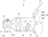
図5は、本発明の吸湿カートリッジを冷房運転に用いる際の空調装置の一例を示す図である。図5に示す空調装置は、図1で示した空調装置、すなわち、切り替えて吸気可能な車内空気流入口11B及び車外空気流入口11Aと、送風機12と、エバポレーター13と、ヒーター14と、車内側吹出口16とを備えた自動車の空調装置を基本構成とする。そして図5の例は、更に車内空気流入口11Bに上記吸湿カートリッジ2が設けられている。冷房運転が必要な夏期は、車内の冷気を循環利用することが多く、車内空気流入口11Bに吸湿カートリッジ2を設けることで、乗員の呼気などに含まれる湿気を吸湿除去できる。また図5の例では、吸湿カートリッジ2と、この吸湿カートリッジの吸湿で生じる熱を冷却するためのクーラント方式の冷却器41と、この冷却器41で使用するクーラントを冷却するための熱交換器45とを備えており、該熱交換器には吸湿カートリッジ2及び/又はエバポレーター13からのドレン水が導かれ、ドレン水が蒸発することでクーラントを冷却可能になっている。冷却器41は、通常、この吸湿カートリッジ2に隣接して(図示例では、吸湿カートリッジ2より下流側に)配置される。吸湿カートリッジ2の吸湿及び/またはエバポレーター13で必然的に発生するドレン水の潜熱を利用し、熱交換器、クーラント、冷却器41を経て吸湿カートリッジ2で発生する吸湿熱を冷却でき、外部からの冷却エネルギーを抑制できるためにエネルギー効率に優れている。なお図5で示している矢印は、空気の流れる方向を意味している。 FIG. 5 is a diagram showing an example of an air conditioner in which the moisture absorption cartridge of the present invention is used for cooling operation. The air conditioner shown in FIG. 5 is the air conditioner shown in FIG. The basic configuration is an air conditioner for an automobile equipped with anair outlet 16. In the example shown in FIG. 5, themoisture absorption cartridge 2 is further provided at the in-vehicle air inlet 11B. During the summer when cooling operation is required, the cold air inside the vehicle is often circulated and used, and by providing themoisture absorption cartridge 2 in theinterior air inlet 11B, it is possible to absorb and remove moisture contained in the exhaled air of the occupants. Further, in the example shown in FIG. 5, amoisture absorption cartridge 2, a coolant type cooler 41 for cooling the heat generated by moisture absorption in the moisture absorption cartridge, and aheat exchanger 45 for cooling the coolant used in this cooler 41 are shown. Drain water from themoisture absorption cartridge 2 and/or theevaporator 13 is led to the heat exchanger, and the coolant can be cooled by evaporating the drain water. The cooler 41 is usually arranged adjacent to the moisture absorption cartridge 2 (in the illustrated example, downstream of the moisture absorption cartridge 2). By using the moisture absorption of themoisture absorption cartridge 2 and/or the latent heat of the drain water inevitably generated in theevaporator 13, the heat of moisture absorption generated in themoisture absorption cartridge 2 can be cooled through the heat exchanger, coolant, and cooler 41. It has excellent energy efficiency because it can suppress cooling energy. Note that the arrows shown in FIG. 5 indicate the direction in which air flows.

冷却器41には、熱交換器45によって冷却されたクーラントが、導かれている。熱交換器45では、具体的には、吸湿カートリッジ2からのドレン水タンク42Aに溜められたドレン水及び/又はエバポレーター13からのドレン水タンク42Bに溜められたドレン水を、ドレン水ポンプ44によってドレン水配管43に供給して熱交換器45に運ぶことができ、このドレン水の蒸発によってクーラントを冷却する。熱交換器45で冷却されたクーラントは、例えば、リザーブタンク47に溜められ、クーラントポンプ48でクーラント配管46により冷却器41に導くことができる。 Coolant cooled by aheat exchanger 45 is guided to the cooler 41 . Specifically, in theheat exchanger 45, the drain water stored in thedrain water tank 42A from themoisture absorption cartridge 2 and/or the drain water stored in thedrain water tank 42B from theevaporator 13 is transferred by thedrain water pump 44. The drain water can be supplied to thedrain water piping 43 and transported to theheat exchanger 45, and the coolant is cooled by evaporation of the drain water. The coolant cooled by theheat exchanger 45 is stored in areserve tank 47, for example, and can be guided to the cooler 41 through acoolant pipe 46 using acoolant pump 48.

送風機12に送られた除湿後の空気は、エバポレーター13で更に冷却され(その際、前記したドレン水が排出される)、エアミックスドア15がヒーター14側に切り替えられることで、ヒーター14を通過しない経路で車内側吹出口16へと流れる。 The dehumidified air sent to theblower 12 is further cooled by the evaporator 13 (at this time, the above-mentioned drain water is discharged), and theair mix door 15 is switched to theheater 14 side, so that the air passes through theheater 14. It flows to theinside air outlet 16 through a route that does not occur.

冷房運転に用いる空調装置では、空調装置稼働時に、車内空気のみを車内空気流入口11Bより取り込んでもよいし、車内空気に加えて、取り込み空気の一部を車外空気流入口11Aより取り込んだ車外空気としてもよい。夏場の空調装置稼働時には、車内温度が車外より一時的に著しく高くなっている場合があり、取り込み空気の一部を車外空気とすることで、車内を冷却するためのエバポレーター13の負荷を下げることができる。 In the air conditioner used for cooling operation, when the air conditioner is operating, only the air inside the vehicle may be taken in through theinside air inlet 11B, or in addition to the inside air, a part of the intake air may be taken in outside air taken in through theoutside air inlet 11A. You can also use it as When the air conditioner is operating in the summer, the temperature inside the car may be temporarily significantly higher than outside the car, so by using some of the air taken in as outside air, the load on theevaporator 13 that cools the inside of the car can be reduced. Can be done.

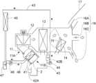
図6は、本発明の吸湿カートリッジを暖房運転に用いた空調装置の一例を示す図である。図6に示す空調装置は、図1で示した空調装置、すなわち、切り替えて吸気可能な車内空気流入口11B及び車外空気流入口11Aと、送風機12と、エバポレーター13と、ヒーター14と、車内側吹出口16とを備えた自動車の空調装置を基本構成とする。そして図6の例は、更にエバポレーター13上流側(図示例では送風機12近傍)とエバポレーター13下流側(図示例では、車内側吹出口16、特にデフロスタ(DEF)吹出口16A)とを結ぶバイパス経路51と、バイパス経路51に設けられた吸湿カートリッジ2を有している。図6の例では、車外空気流入口11A又は車内空気流入口11Bから取り込まれた空気は、送風機12によって、エバポレーター13側とバイパス経路51側に流れる。エバポレーター13側に流れた空気は、エバポレーター13を通過後、エアミックスドア15の切り替えによってヒーター14を通過して車内側吹出口16(図示例では、デフロスタ(DEF)吹出口16A及びフット(FOOT)吹出口16C)へと流れる。
バイパス経路51側に流れた空気は、吸湿カートリッジ2で除湿され、エバポレーター13での冷却なしに除湿でき、また吸着熱によって除湿後の空気が温められるため、暖房効率を高めることができる。なお図6で示している矢印は、空気の流れる方向を意味している。
FIG. 6 is a diagram showing an example of an air conditioner using the moisture absorption cartridge of the present invention for heating operation. The air conditioner shown in FIG. 6 is the air conditioner shown in FIG. The basic configuration is an air conditioner for an automobile equipped with anair outlet 16. In the example of FIG. 6, a bypass path further connects the upstream side of the evaporator 13 (near theblower 12 in the illustrated example) and the downstream side of the evaporator 13 (in the illustrated example, theinside air outlet 16, particularly the defroster (DEF)outlet 16A). 51, and amoisture absorption cartridge 2 provided in thebypass path 51. In the example of FIG. 6, air taken in from theoutside air inlet 11A or theinside air inlet 11B flows to theevaporator 13 side and thebypass path 51 side by theblower 12. After passing through theevaporator 13, the air flowing to theevaporator 13 side passes through theheater 14 by switching theair mix door 15, and then passes through the inside air outlet 16 (in the illustrated example, the defroster (DEF)air outlet 16A and the foot (FOOT)). It flows to theair outlet 16C).
The air flowing to thebypass path 51 side is dehumidified by themoisture absorption cartridge 2 and can be dehumidified without cooling by theevaporator 13, and the air after dehumidification is warmed by the heat of adsorption, so heating efficiency can be increased. Note that the arrows shown in FIG. 6 indicate the direction in which air flows.

吸湿カートリッジ2を通過した後の空気は、車内側空気吹出口16に直接繋がる経路51Aに導かれてもよいし、バイパス経路のエバポレーター13よりも下流に、吸湿カートリッジ2からの除湿された空気をエバポレーター13ーとヒーター14の間に戻す分岐経路51Bを設けて、エバポレーター13ーとヒーター14の間に導いてもよい。経路51Aと51Bへの空気の流れは、空気切替弁53によって切り替えることができる。また、経路51Aは、ヒーター14と車内側吹出口16の間に接続して、デフロスタ(DEF)吹出口16A、フェイス(FACE)吹出口16B、フット(FOOT)吹出口16Cの少なくともいずれかから吸湿カートリッジ2からの除湿された空気を吹き出してもよいし、経路51Aをデフロスタ(DEF)吹出口16A、フェイス(FACE)吹出口16B、フット(FOOT)吹出口16Cに直接に接続して吹出口16A、16B及び16Cのいずれかから吸湿カートリッジ2からの除湿された空気を吹き出してもよく、特に図6に示すように、経路51Aをデフロスタ(DEF)吹出口16Aに接続して、吸湿カートリッジ2からの除湿された空気をフロントガラス17に向けることが好ましい。吸湿カートリッジ2からの除湿された空気をフロントガラス17に向けることで、フロントガラス17の曇りを効率的に除去することができる。 The air after passing through themoisture absorption cartridge 2 may be guided to apath 51A that directly connects to theinside air outlet 16, or the dehumidified air from themoisture absorption cartridge 2 may be introduced downstream of theevaporator 13 in the bypass path. Abranch path 51B may be provided between the evaporator 13 and theheater 14 to lead the water back between the evaporator 13 and theheater 14. Air flow topaths 51A and 51B can be switched byair switching valve 53. Thepath 51A is connected between theheater 14 and theinside air outlet 16, and absorbs moisture from at least one of the defroster (DEF)outlet 16A, the face (FACE)outlet 16B, and the foot (FOOT)outlet 16C. The dehumidified air from thecartridge 2 may be blown out, or thepath 51A may be directly connected to the defroster (DEF)outlet 16A, the face (FACE)outlet 16B, and the foot (FOOT)outlet 16C. , 16B and 16C, the dehumidified air from themoisture absorption cartridge 2 may be blown out from themoisture absorption cartridge 2. In particular, as shown in FIG. It is preferable to direct the dehumidified air towards thewindshield 17. By directing the dehumidified air from themoisture absorption cartridge 2 toward thewindshield 17, fogging on thewindshield 17 can be efficiently removed.

2 吸湿カートリッジ
11A 車外空気流入口
11B 車内空気流入口
12 送風機
13 エバポレーター
14 ヒーター
16 車内側吹出口
20 デシカント収容容器
21A 除湿経路
21B 空気循環路
22 熱交換部
23 水の排出口
24 ヒーター
25 回転モーター
27 空気流入口
28 空気排出口
30 デシカント
30A 吸湿域
30B 脱着域
29A 隔壁
31 顕熱交換ローター
32 除湿経路の空気の流れ
41 冷却器
45 熱交換器
51 バイパス経路
2Moisture absorption cartridge 11AExternal air inlet 11B In-vehicle air inlet 12Blower 13Evaporator 14Heater 16 In-vehicle outlet 20Desiccant container21A Dehumidification path 21BAir circulation path 22Heat exchange section 23Water outlet 24Heater 25Rotating motor 27Air inlet 28Air outlet 30Desiccant 30AMoisture absorption area30B Desorption area29A Partition wall 31 Sensibleheat exchange rotor 32 Air flow indehumidification route 41Cooler 45Heat exchanger 51 Bypass route

Claims (9)

Translated fromJapanese
デシカント収容容器を備える吸湿カートリッジであって、
前記容器は、除湿経路と、容器内で循環し水の排出口を有する空気循環路と、前記除湿経路の空気と前記空気循環路の空気の熱のやり取りを可能にする熱交換部と、デシカントと、ヒーターとを有し、
前記デシカントは、吸湿域と、吸湿した水分の脱着域とを備え、
前記熱交換部は、前記除湿経路の一部と、前記空気循環路の一部とが接触してなり、
前記除湿経路は、空気を前記容器に取り込むための空気流入口と、前記熱交換部と、前記吸湿域と、前記吸湿域を通って除湿された空気を前記容器外に排出する空気排出口とを前記除湿経路に沿ってこの順で備え、
前記空気循環路は、ヒーターと、前記脱着域と、前記熱交換部と、前記熱交換部における前記除湿経路との熱交換によって生じる水の排出口とを前記空気循環路に沿ってこの順で備える吸湿カートリッジ。
A moisture absorption cartridge comprising a desiccant storage container,
The container includes a dehumidification path, an air circulation path that circulates within the container and has a water outlet, a heat exchange section that enables exchange of heat between the air in the dehumidification path and the air in the air circulation path, and a desiccant. and a heater,
The desiccant includes a moisture absorption area and a desorption area for absorbed moisture,
The heat exchange part is formed by a part of the dehumidification path and a part of the air circulation path being in contact with each other,
The dehumidification path includes an air inlet for taking air into the container, the heat exchange section, the moisture absorption area, and an air outlet for exhausting the dehumidified air through the moisture absorption area to the outside of the container. are provided in this order along the dehumidification path,
The air circulation path connects the heater, the desorption region, the heat exchange section, and a discharge port for water generated by heat exchange with the dehumidification path in the heat exchange section in this order along the air circulation path. Equipped with a moisture absorption cartridge.
前記デシカントに回転モーターが取り付けられ、除湿経路に存在する吸湿域と空気循環路に存在する脱着域がデシカントの回転によって交換される請求項1に記載の吸湿カートリッジ。 2. The moisture absorbing cartridge according to claim 1, wherein a rotation motor is attached to the desiccant, and a moisture absorption area existing in the dehumidification path and a desorption area existing in the air circulation path are exchanged by rotation of the desiccant. 前記除湿経路で、自動車の車室内の内気を容器内に取り入れ、除湿された気体を車室内に排気する請求項1または2に記載の吸湿カートリッジ。 The moisture absorbing cartridge according to claim 1 or 2, wherein the dehumidification path takes inside air from inside the vehicle interior into the container and exhausts the dehumidified gas into the interior of the vehicle. 前記デシカントが、二酸化炭素吸着性の金属有機構造体である請求項1または2に記載の吸湿カートリッジ。 The moisture absorption cartridge according to claim 1 or 2, wherein the desiccant is a metal organic structure capable of adsorbing carbon dioxide. 更に、前記除湿経路の空気の流れの上流側に、前記デシカントと所定の距離を隔てて、又は所定の距離を隔てることなく顕熱交換ローターを有する請求項1または2に記載の吸湿カートリッジ。 The moisture absorption cartridge according to claim 1 or 2, further comprising a sensible heat exchange rotor on the upstream side of the air flow of the dehumidification path, separated from the desiccant by a predetermined distance, or without being separated by a predetermined distance. 切り替えて吸気可能な車内空気流入口及び車外空気流入口と、送風機と、エバポレーターと、ヒーターと、車内側吹出口とを備えた自動車の空調装置であって、
さらに前記車内空気流入口に設けられた請求項1または2に記載の吸湿カートリッジと、
前記吸湿カートリッジを冷却するためのクーラント方式の冷却器と、
前記吸湿カートリッジ及び/又は前記エバポレーターからのドレン水と前記冷却器からのクーラントが導かれ、ドレン水の蒸発でクーラントを冷却する熱交換器とを有する自動車の空調装置。
An air conditioner for an automobile comprising an interior air inlet and an exterior air inlet that can be switched to intake air, a blower, an evaporator, a heater, and an interior air outlet,
The moisture absorption cartridge according to claim 1 or 2, further provided at the in-vehicle air inlet;
a coolant-type cooler for cooling the moisture absorption cartridge;
An air conditioner for an automobile, comprising a heat exchanger to which drain water from the moisture absorption cartridge and/or the evaporator and coolant from the cooler are introduced, and which cools the coolant by evaporation of the drain water.
切り替えて吸気可能な車内空気流入口及び車外空気流入口と、送風機と、エバポレーターと、ヒーターと、車内側吹出口とを備えた自動車の空調装置であって、
さらにエバポレーター上流側と車内側吹出口とを結ぶバイパス経路を有し、前記バイパス経路に請求項1または2に記載の吸湿カートリッジが設けられている自動車の空調装置。
An air conditioner for an automobile, comprising an inside air inlet and an outside air inlet that can be switched to intake air, a blower, an evaporator, a heater, and an inside air outlet,
An air conditioner for an automobile, further comprising a bypass path connecting the upstream side of the evaporator and a vehicle interior air outlet, and the moisture absorption cartridge according to claim 1 or 2 is provided in the bypass path.
前記バイパス経路の吸湿カートリッジよりも下流に、吸湿カートリッジからの除湿された空気を前記エバポレーターとヒーターの間に戻す分岐経路が設けられている請求項7に記載の自動車の空調装置。 8. The air conditioner for an automobile according to claim 7, further comprising a branch path downstream of the moisture absorption cartridge in the bypass path for returning dehumidified air from the moisture absorption cartridge between the evaporator and the heater. 前記車内側吹出口が自動車のフロントガラスに向けられたものである請求項7に記載の自動車の空調装置。 The air conditioner for an automobile according to claim 7, wherein the inside air outlet is directed toward a windshield of the automobile.
JP2022138751A2022-08-312022-08-31 Moisture absorption cartridge and automobile air conditioner using the samePendingJP2024034493A (en)

Priority Applications (1)

Application NumberPriority DateFiling DateTitle
JP2022138751AJP2024034493A (en)2022-08-312022-08-31 Moisture absorption cartridge and automobile air conditioner using the same

Applications Claiming Priority (1)

Application NumberPriority DateFiling DateTitle
JP2022138751AJP2024034493A (en)2022-08-312022-08-31 Moisture absorption cartridge and automobile air conditioner using the same

Publications (1)

Publication NumberPublication Date
JP2024034493Atrue JP2024034493A (en)2024-03-13

Family

ID=90194535

Family Applications (1)

Application NumberTitlePriority DateFiling Date
JP2022138751APendingJP2024034493A (en)2022-08-312022-08-31 Moisture absorption cartridge and automobile air conditioner using the same

Country Status (1)

CountryLink
JP (1)JP2024034493A (en)

Similar Documents

PublicationPublication DateTitle
US6205805B1 (en)Motor vehicle dehumidifier with drying agent and drying agent regenerative control
JP4337402B2 (en) Air conditioner, operation method of air conditioner
US5509275A (en)Dehumidifying mechanism for auto air conditioner
ES2798125T3 (en) Device for the purification of air charged with CO2 in the passenger compartment of a motor vehicle in the recirculation mode of an adsorption device
TW200307111A (en)Dehumidifier
JP3050810B2 (en) Air drying equipment
CN111439092A (en)Air cleaning device for vehicle
WO2011071192A1 (en)Antifogging air conditioning system for electric vehicle
JP2009274587A (en)Dehumidifying and humidifying device for vehicle
WO2015019577A1 (en)Vehicle heating device
JP2010260472A (en)Dehumidifier system for vehicle
JP2016064695A (en) Air conditioner for vehicles
JP3837339B2 (en) Dehumidification cooling unit
JP2009154862A (en) Electric vehicle air conditioning system
JP5089254B2 (en) Humidity conditioning air conditioning system for automobiles
JP2024034493A (en) Moisture absorption cartridge and automobile air conditioner using the same
JP2010121921A (en)Air conditioning system equipped with static dehumidifier
JP6304164B2 (en) Humidifier
JP3774963B2 (en) Heating system
JP2011110951A (en)Air conditioner for vehicle
JP2001047844A (en)Vehicular air conditioner
JP6289881B2 (en) Air conditioner for vehicles
JP2008201199A (en)Air conditioner for vehicle
JP2013014307A (en)Vehicle air conditioning apparatus
WO2024227804A1 (en)Plug-in vehicle with air heating and dehumidification module

[8]ページ先頭

©2009-2025 Movatter.jp