JP2024033183A - Auxiliary grip for impact tools - Google Patents
Auxiliary grip for impact toolsDownload PDFInfo
- Publication number
- JP2024033183A JP2024033183AJP2022136620AJP2022136620AJP2024033183AJP 2024033183 AJP2024033183 AJP 2024033183AJP 2022136620 AJP2022136620 AJP 2022136620AJP 2022136620 AJP2022136620 AJP 2022136620AJP 2024033183 AJP2024033183 AJP 2024033183A
- Authority
- JP
- Japan
- Prior art keywords
- grip
- striking
- shaft
- auxiliary
- impact
- Prior art date
- Legal status (The legal status is an assumption and is not a legal conclusion. Google has not performed a legal analysis and makes no representation as to the accuracy of the status listed.)
- Pending
Links
Images


Classifications
- B—PERFORMING OPERATIONS; TRANSPORTING
- B25—HAND TOOLS; PORTABLE POWER-DRIVEN TOOLS; MANIPULATORS
- B25F—COMBINATION OR MULTI-PURPOSE TOOLS NOT OTHERWISE PROVIDED FOR; DETAILS OR COMPONENTS OF PORTABLE POWER-DRIVEN TOOLS NOT PARTICULARLY RELATED TO THE OPERATIONS PERFORMED AND NOT OTHERWISE PROVIDED FOR
- B25F5/00—Details or components of portable power-driven tools not particularly related to the operations performed and not otherwise provided for
- B25F5/02—Construction of casings, bodies or handles
- B25F5/025—Construction of casings, bodies or handles with torque reaction bars for rotary tools
- B25F5/026—Construction of casings, bodies or handles with torque reaction bars for rotary tools in the form of an auxiliary handle
- B—PERFORMING OPERATIONS; TRANSPORTING
- B25—HAND TOOLS; PORTABLE POWER-DRIVEN TOOLS; MANIPULATORS
- B25D—PERCUSSIVE TOOLS
- B25D17/00—Details of, or accessories for, portable power-driven percussive tools
- B25D17/04—Handles; Handle mountings
- B—PERFORMING OPERATIONS; TRANSPORTING
- B25—HAND TOOLS; PORTABLE POWER-DRIVEN TOOLS; MANIPULATORS
- B25D—PERCUSSIVE TOOLS
- B25D17/00—Details of, or accessories for, portable power-driven percussive tools
- B25D17/24—Damping the reaction force
Landscapes
- Engineering & Computer Science (AREA)
- Mechanical Engineering (AREA)
- Percussive Tools And Related Accessories (AREA)
- Portable Power Tools In General (AREA)
Abstract
Description
Translated fromJapanese本開示は、例えばハンマードリルと称される打撃工具用の補助グリップに関する。 The present disclosure relates to an auxiliary grip for a striking tool, for example a hammer drill.
特許文献1,2に開示されているようにハンマードリルと称される打撃工具は、使用者が一方の手で把持するメインハンドルと他方の手で把持する補助グリップを備える。使用者は両手で打撃工具を把持して、例えばコンクリート壁の穴明け作業やコンクリート床のハツリ作業を行う。使用者は作業中打撃方向に大きな衝撃を受けるため、例えば補助グリップには衝撃吸収のための工夫がなされている。 As disclosed in
従来、補助グリップは、工具本体に結合されるグリップベースとの間にスポンジ等の弾性体を介在させてグリップ本体を支持することで、使用者の手に付加される衝撃を吸収する構成となっている。しかしながら、従来の衝撃吸収構造では、グリップ本体に対して打撃方向へ大きな押し荷重を加えると、弾性体による衝撃吸収機能(防振機能)が低下して使用者の負担が大きくなる問題があった。この点で従来の補助グリップは衝撃吸収機能をより高める必要があった。本開示では、補助グリップの衝撃吸収機能をより高めることを目的とする。 Conventionally, auxiliary grips have a structure in which an elastic body such as a sponge is interposed between the grip base connected to the tool body to support the grip body, thereby absorbing shocks applied to the user's hand. ing. However, with conventional shock-absorbing structures, when a large pushing load is applied to the grip body in the direction of impact, the shock-absorbing function (vibration-proofing function) of the elastic body decreases, which increases the burden on the user. . In this respect, conventional auxiliary grips needed to have a higher impact absorption function. The present disclosure aims to further enhance the shock absorption function of the auxiliary grip.
本開示の1つの局面によれば、打撃工具用補助グリップは、例えば先端工具を打撃方向に往復動する工具本体から打撃方向に交差して延出するグリップ軸と、グリップ軸を覆う筒状のグリップ本体を有する。打撃工具用補助グリップは、例えばグリップ本体をグリップ軸の先端部において打撃方向にスライド可能に連結する連結機構を有する。 According to one aspect of the present disclosure, the auxiliary grip for an impact tool includes, for example, a grip shaft that extends from a tool body that reciprocates the tip tool in the impact direction, and a cylindrical grip that covers the grip shaft. It has a grip body. The auxiliary grip for an impact tool has, for example, a connection mechanism that connects the grip main body slidably in the impact direction at the tip of the grip shaft.
従って、グリップ本体がグリップ軸に対して打撃方向にスライドすることで打撃方向の衝撃が吸収される。これにより、グリップ本体を把持した使用者に対する打撃方向の衝撃吸収機能がより高められる。これにより打撃工具の使用者の負担が低減される。 Therefore, the impact in the striking direction is absorbed by the grip body sliding in the striking direction with respect to the grip shaft. This further enhances the shock absorption function in the direction of impact for the user who grips the grip body. This reduces the burden on the user of the impact tool.
本開示の他の局面によれば、例えば打撃工具は、打撃工具用補助グリップを有する。従って補助グリップを把持して打撃工具を使用する使用者に対する打撃方向の衝撃吸収機能がより高められる。これにより打撃工具の使用者の負担が低減される。 According to another aspect of the present disclosure, for example, the impact tool has an auxiliary grip for the impact tool. Therefore, the impact absorption function in the direction of impact for the user who uses the impact tool while holding the auxiliary grip is further enhanced. This reduces the burden on the user of the impact tool.
1つ又はそれ以上の実施態様において、打撃工具用補助グリップは、例えばグリップ軸の先端部とグリップ本体の間に設けられてグリップ本体のグリップ軸に対する打撃方向の衝撃を吸収する第1クッションを有する。 In one or more embodiments, the auxiliary grip for a striking tool includes a first cushion that is provided, for example, between the tip of the grip shaft and the grip body and absorbs the impact of the grip body in the striking direction with respect to the grip shaft. .
従って、グリップ本体の打撃方向の衝撃が第1クッションにより吸収されることで、補助グリップの衝撃吸収機能がより高められる。 Therefore, the impact of the grip body in the direction of impact is absorbed by the first cushion, thereby further enhancing the impact absorption function of the auxiliary grip.
1つ又はそれ以上の実施態様において、打撃工具用補助グリップは、例えばグリップ軸の工具本体側の基部とグリップ本体の間に設けられてグリップ本体のグリップ軸に対する打撃方向の衝撃を吸収する第2クッションを有する。 In one or more embodiments, the auxiliary grip for a striking tool is provided with a second grip provided between the base of the grip shaft on the side of the tool body and the grip body to absorb the impact of the grip body against the grip shaft in the striking direction. Has a cushion.
従って、グリップ本体の打撃方向の衝撃が第2クッションにより吸収されることで、補助グリップの衝撃吸収機能がより高められる。 Therefore, the second cushion absorbs the impact of the grip body in the direction of impact, thereby further enhancing the impact absorption function of the auxiliary grip.
1つ又はそれ以上の実施態様において、例えば第2クッションは、グリップ軸に対して打撃方向に直交する方向に隣接する横側部と、横側部より肉厚でかつグリップ軸の打撃方向に隣接する縦側部を有する。 In one or more embodiments, the second cushion, for example, has a lateral portion adjacent to the grip axis in a direction perpendicular to the striking direction, and a lateral portion that is thicker than the lateral portion and adjacent to the grip axis in the striking direction. It has vertical sides.
従って、第2クッションの縦側部により打撃方向の衝撃がより確実に吸収される。 Therefore, the impact in the direction of impact is more reliably absorbed by the vertical side portions of the second cushion.
1つ又はそれ以上の実施態様において、例えばグリップ軸には、第2クッションよりも硬く第2クッションが弾性変形した後にグリップ本体と当接する第3クッションが設けられている。 In one or more embodiments, for example, the grip shaft is provided with a third cushion that is harder than the second cushion and comes into contact with the grip body after the second cushion is elastically deformed.
従って、第2クッションの衝撃吸収機能を超える衝撃がグリップ本体に付加された場合に、第3クッションによりグリップ本体がグリップ軸に直接当接することが回避される。これにより補助グリップの衝撃吸収機能が高められる。 Therefore, when an impact exceeding the impact absorption function of the second cushion is applied to the grip body, the third cushion prevents the grip body from directly contacting the grip shaft. This enhances the shock absorption function of the auxiliary grip.
1つ又はそれ以上の実施態様において、例えば連結機構は、グリップ軸とグリップ本体の少なくとも一方に、打撃方向に延在して設けられて他方が当接される当接面を有する。 In one or more embodiments, for example, the coupling mechanism has an abutment surface on at least one of the grip shaft and the grip body that extends in the striking direction and abuts the other.
従って、当接面にグリップ軸又はグリップ本体の他方が当接されることで、グリップ本体がグリップ軸に対して打撃方向にスライド支持される。 Therefore, by bringing the other of the grip shaft or the grip main body into contact with the contact surface, the grip main body is slidably supported in the striking direction with respect to the grip shaft.
1つ又はそれ以上の実施態様において、例えば連結機構は、打撃方向と直交する方向にグリップ軸を貫通する貫通孔と、貫通孔を貫通しかつグリップ本体に連結された連結部材を有する。例えば連結部材は、当接面として打撃方向と平行な平坦面を有し、グリップ軸の貫通孔は、当接面として連結部材の平坦面に対向する受け面を有する。 In one or more embodiments, for example, the coupling mechanism has a through hole that passes through the grip shaft in a direction perpendicular to the striking direction, and a coupling member that passes through the through hole and is coupled to the grip body. For example, the connecting member has a flat surface parallel to the hitting direction as the abutting surface, and the through hole of the grip shaft has a receiving surface opposite to the flat surface of the connecting member as the abutting surface.
従って、連結部材が軸回りに回転することなく打撃方向(連結部材の径方向)に平行移動して受け面に摺接されることで、グリップ本体が打撃方向にスライドされる。これにより打撃方向の衝撃が吸収される。 Therefore, the connecting member moves parallel in the striking direction (radial direction of the connecting member) without rotating around the axis and slides into sliding contact with the receiving surface, thereby causing the grip body to slide in the striking direction. This absorbs the impact in the direction of impact.
1つ又はそれ以上の実施態様において、例えばグリップ軸の貫通孔は、打撃方向に長い長溝孔形状を有し、貫通孔の内面に受け面を有する。 In one or more embodiments, for example, the through hole of the grip shaft has a slot shape that is elongated in the direction of impact, and has a receiving surface on the inner surface of the through hole.
従って、簡易な構成の連結機構によりグリップ本体のグリップ軸に対するスライド動作が確実になされる。 Therefore, the sliding movement of the grip body with respect to the grip shaft can be reliably performed by the simple connecting mechanism.
1つ又はそれ以上の実施態様において、例えば連結機構は、打撃方向にグリップ軸を貫通する貫通孔と、貫通孔を貫通しグリップ本体に連結される連結部材を有する。 In one or more embodiments, for example, the coupling mechanism has a through hole that passes through the grip shaft in the striking direction and a coupling member that passes through the through hole and is coupled to the grip body.
従って、連結部材がグリップ軸の貫通孔内を打撃方向(連結部材の軸方向)に移動することで、グリップ本体がグリップ軸に対して打撃方向にスライドされる。これにより打撃方向の衝撃が吸収される。 Therefore, when the connecting member moves in the through hole of the grip shaft in the striking direction (the axial direction of the connecting member), the grip body is slid in the striking direction with respect to the grip shaft. This absorbs the impact in the direction of impact.
1つ又はそれ以上の実施態様において、グリップ本体の少なくとも打撃方向の外面にエラストマ層を有し、エラストマ層がエラストマ層より硬質の樹脂層に一体成形されている。 In one or more embodiments, the grip body has an elastomer layer on at least the outer surface in the direction of impact, and the elastomer layer is integrally molded with a resin layer that is harder than the elastomer layer.
従って、打撃方向の衝撃がエラストマ層によっても吸収される。これにより使用者の負担が低減される。 Therefore, the impact in the direction of impact is also absorbed by the elastomer layer. This reduces the burden on the user.
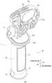
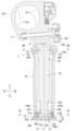
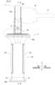
図1に示すように第1実施例に係る補助グリップ1は、ハンマードリルと称される打撃工具50に取り付けて用いられる。打撃工具50は、比較的大型の手持ち工具で、打撃機構60を内装した工具本体51と、使用者が把持するループ形のハンドル部52を備えている。工具本体51とハンドル部52との間には、複数組の防振機構53が介在されており、両者間は剛体結合ではなく相互に弾性支持された防振構造を備えている。防振機構53は、圧縮コイルばねを主体とするもので、工具本体51の打撃機構60側で発生する衝撃を吸収してハンドル部52側への衝撃伝達を抑制する機能を有している。 As shown in FIG. 1, the
工具本体51は、本体ハウジング54を有する。本体ハウジング54に打撃機構60が内装されている。打撃機構60は、駆動源として電動モータ61を有する。電動モータ61はモータ軸線Mを上下に平行に位置させた縦向き姿勢に支持されている。電動モータ61の回転出力は、ベベルギア62を経て中間軸63に伝達される。中間軸63は、軸線Jを前後に平行に位置させた横向き姿勢で軸線J回りに回転可能に支持されている。 The
中間軸63の回転により動力変換部材64が前後に傾動する。動力変換部材64はピストン65に連結されている。従って中間軸63の回転によりピストン65が前後に往復動する。ピストン65の往復動により発生する空気圧により打撃子66が前方へ移動して中間子68に当接する。中間子68によりドリルビットBの後端が打撃される。中間子68の打撃力によりドリルビットBが被加工体Wに向けて打撃される。本実施例の場合、ドリルビットBの軸線が出力軸線Pに相当する。ドリルビットBは出力軸線Pに沿って前方(打撃方向)に打撃される。 The rotation of the
中間軸63の回転によりツールホルダ67が出力軸線P回りに回転する。ツールホルダ67の後部側は円筒形を有している。ツールホルダ67の内周側にピストン65及び打撃子66が往復動可能に収容されている。ツールホルダ67の前部側にドリルビットBが着脱可能に装着される。ドリルビットBは、本体ハウジング54の前部に設けたチャック55から前方へ突き出される。電動モータ61の回転出力により、ツールホルダ67に取り付けたドリルビットBに対して出力軸線P回りの回転動作と出力軸線P方向の打撃動作が与えられる。 The rotation of the
ハンドル部52は、工具本体51の後部側上部と後部側下部との間に跨るループ形を有している。ハンドル部52は、使用者が実際に把持するグリップ部56と、台座部57を備えている。台座部57の後部からグリップ部56が上方へ延びる状態に設けられている。グリップ部56の上部は、防振機構53を介して工具本体51の後部側上部に連結されている。 The
グリップ部56の前面(ループ内側)にスイッチレバー58が設けられている。スイッチレバー58の後側には、スイッチ本体59が内装されている。グリップ部56を把持した手(例えば右手)の指先でスイッチレバー58を後方側へ引き操作するとスイッチ本体59がオンして電動モータ61が起動する。 A
台座部57の下面側に、1つのバッテリパック70を取り付けるためのバッテリ取付部71が設けられている。バッテリパック70は直方体形を有するスライド取り付け形式のリチウムイオンバッテリで、バッテリ取付部71に対して前方へスライドさせて取り付けられる。取り付けたバッテリパック70の電力を電源として電動モータ61が起動する。台座部57には矩形平板形のコントローラ72が内装されている。コントローラ72により主として電動モータ61の動作制御がなされる。 A
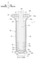
打撃工具50は、使用者が一方の手(例えば右手)でハンドル部52のグリップ部56は把持し、他方の手(例えば左手)で補助グリップ1を把持して用いられる。補助グリップ1は、本体ハウジング54の前部に設けた円筒形のグリップ取付部54aに取り付けられる。グリップ取付部54aに取り付けられた補助グリップ1は、打撃方向(出力軸線P)に交差する方向に延出される。図2~4にはグリップ取付部54aから取り外した補助グリップ1が示されている。補助グリップ1は、グリップ軸10とグリップ本体20を有する。グリップ軸10は、グリップ取付部54aから打撃方向にほぼ直交する方向に延在される。 The
グリップ軸10の上部には、長円形のフランジ部10bが一体に設けられている。フランジ部10bの上面側に円環形の締付部10aが一体に設けられている。締付部10aは固定ねじ11の締め込みにより縮径方向に変位する。締付部10aの内周側にグリップ取付部54aを位置させて、固定ねじ11を締め込むことによりグリップ軸10がグリップ取付部54aに結合される。 An
締付部10aの内周側には、複数の係合凹部10cが設けられている。何れかの係合凹部10cにグリップ取付部54a側の係合凸部54b(図1参照)に嵌まり込むことで、グリップ軸10の出力軸線P回りの位置が固定される。 A plurality of
固定ねじ11を緩めることで締付部10aが拡径方向へ弾性変形する。これによりグリップ取付部54aに対する締付部10aの結合状態が緩められて、補助グリップ1をグリップ取付部54aから取り外すことができる。また、グリップ取付部54aに対する締付部10aの結合状態を緩めることで、グリップ軸10を出力軸線P回りの位置を変更することができる。位置を変更した状態で固定ねじ11を締め込んでグリップ取付部54aの係合凸部54bが別の係合凹部10cに嵌まり込むことでグリップ軸10の位置が固定される。これにより補助グリップ1がグリップ取付部54aから下方へ延びる縦姿勢(図1に示す姿勢)、あるいは左方又は右方へ延びる横姿勢に任意に変更することができる。 By loosening the fixing
図4,5に示すようにグリップ本体20は、グリップ軸10の周囲を覆う筒状を有する。グリップ本体20は、フランジ部10bの下方側においてグリップ軸10に支持される。グリップ本体20の上部には側方へ湾曲形に開口する開口部20aが設けられている。開口部20aはグリップ軸10のフランジ部10bによりほぼ塞がれた状態となる。側方へ拡径される開口部20aにより把持部位の上端部が規制されて補助グリップ1の把持性が高められる。 As shown in FIGS. 4 and 5, the
グリップ本体20は、グリップ軸10の下端部において連結機構12を介して連結されている。グリップ軸10の下端部には、左右の平坦面10da,10dbを有する二面幅部10dが設けられている。グリップ本体20の下端部には、左右の連結台座部20b,20cが一体に設けられている。左右の連結台座部20b,20c間にグリップ軸10の二面幅部10dが進入している。 The grip
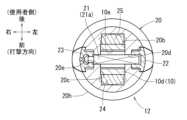
左右の連結台座部20b,20cには、支持孔20d,20eが相互に同軸に設けられている。左右の支持孔20d,20eは、連結部材21を挿通可能な円形孔に形成されている。グリップ軸10の二面幅部10dに、1つの貫通孔10eが設けられている。図4~6に示すように貫通孔10eは、二面幅部10dを左右に貫通している。図5,6に示すように貫通孔10eは、前後に長い長溝孔形状を有する。図4,5に示すように貫通孔10eの上下には平坦な受け面10f,10gが相互に平行に設けられている。
左右の支持孔20d,20eと貫通孔10e間に跨って1本の連結部材21が挿通されている。連結部材21には相互に平行な上下の平坦面21a,21bが設けられている。このため連結部材21は軸回りの回転が規制された状態で貫通孔10e内を前後に平行移動可能となっている。このように構成した連結機構12によりグリップ本体20の下部がグリップ軸10の下部に対して前後にスライド可能に連結されている。 One connecting
連結部材21の左右端部は、グリップ本体20に設けた凹部20f,20g内に突き出されている。凹部20f,20gはそれぞれキャップ22,23により塞がれている。キャップ22,23により連結部材21の左右端部が覆われている。グリップ本体20の下部には、湾曲形に拡径する拡径部20hが設けられている。左右のキャップ22,23は、拡径部20hの湾曲形状に沿ってはみ出さないように凹部20f,20gに嵌め付けられる。拡径部20hによりグリップ本体20の把持部位の下端部が規制されて補助グリップ1の把持性が高められる。 The left and right end portions of the connecting
図5,6に示すようにグリップ軸10の二面幅部10dの前面とグリップ本体20との間と、二面幅部10dの後面とグリップ本体20との間にそれぞれ第1クッション24,25が介装されている。第1クッション24,25によりグリップ本体20に対する打撃方向の衝撃が吸収される。 As shown in FIGS. 5 and 6,
図4,5に示すようにグリップ本体20の開口部20aとグリップ軸10の工具本体51側の基部10hとの間に第2クッション28が介装されている。第2クッション28は、グリップ軸10に対して前後方向(打撃方向)に隣接する縦側部28aと、グリップ軸10に対して左右方向に隣接する横側部28bを有する長円形を有している。縦側部28aの肉厚d1は、横側部28bの肉厚d2よりも大きくなっている(d1>d2)。第2クッション28によりグリップ本体20の主として上部側の衝撃が吸収される。第2クッション28は縦側部28aの肉厚d1が横側部28bの肉厚d2よりも肉厚に形成されることで、特に前後方向(打撃方向)の衝撃吸収能力が高められている。 As shown in FIGS. 4 and 5, a
第2クッション28の下方においてグリップ軸10に第3クッション29が取り付けられている。第3クッション29はグリップ軸10の全周にわたって取り付けられている。第3クッション29には例えばO形のゴムリングが用いられる。第2クッション28の衝撃吸収能力を超える衝撃がグリップ本体20に付加された場合に、グリップ本体20が第3クッション29に当接する。これによりグリップ本体20がグリップ軸10に直接当接することが回避される。これにより補助グリップ1の衝撃吸収能力が高められる。 A
図1,2,3,5に示すようにグリップ本体20の前面及び後面にはそれぞれエラストマ層26,27が被覆されている。エラストマ層26,27により使用者の手の滑り止めがなされるとともに、打撃方向の衝撃が吸収される。エラストマ層26,27はグリップ本体20の前面及び後面にのみ被覆されており、左右の側面についてはエラストマ層は省略されている。エラストマ層26,27は、より硬質の樹脂層であるグリップ本体20に一体成形されている。 As shown in FIGS. 1, 2, 3, and 5, the front and rear surfaces of the
以上のように構成した第1実施例によれば、補助グリップ1の連結機構12において、グリップ本体20がグリップ軸10に対して打撃方向にスライドすることで打撃方向の衝撃が吸収される。これにより、グリップ本体20を把持した使用者に対する打撃方向の衝撃吸収機能がより高められる。これにより打撃工具50の使用者の負担が低減される。 According to the first embodiment configured as described above, in the
第1実施例によれば、補助グリップ1は、グリップ軸10の先端部とグリップ本体20の間に設けられてグリップ本体20のグリップ軸10に対する打撃方向の衝撃を吸収する第1クッション24,25を有する。グリップ本体20の打撃方向の衝撃が第1クッション24,25により吸収されることで、補助グリップ1の衝撃吸収機能がより高められる。 According to the first embodiment, the
第1実施例によれば、補助グリップ1は、グリップ軸10の工具本体51側の基部10hとグリップ本体20の間に第2クッション28が介装されている。第2クッション28によりグリップ本体20のグリップ軸10に対する打撃方向の衝撃が吸収される。第2クッション28の縦側部28aの肉厚d1は横側部28bの肉厚d2よりも肉厚(d1>d2)に形成されている。これにより打撃方向の衝撃吸収能がより高められている。 According to the first embodiment, in the
第1実施例によれば、グリップ軸10には、第2クッション28よりも硬く第2クッション28が弾性変形した後にグリップ本体20と当接する第3クッション29が設けられている。第2クッション28の衝撃吸収機能を超える衝撃がグリップ本体20に付加された場合に、第3クッション29によりグリップ本体20がグリップ軸10に直接当接することが回避される。これにより補助グリップ1の衝撃吸収機能が高められる。 According to the first embodiment, the
第1実施例によれば、連結機構12は、打撃方向と直交する方向にグリップ軸10を貫通する貫通孔10eと、貫通孔10eを貫通しかつグリップ本体20に連結された連結部材21を有する。連結部材21には、打撃方向と平行な平坦面21a,21bが設けられている。平坦面21a,21bには、貫通孔10eの受け面10f,10gが摺接されている。このため連結部材21は軸回りの回転が規制された状態で貫通孔10e内を前後に平行移動可能となっている。これによりグリップ本体20の下部がグリップ軸10の下部に対して前後にスライド可能に連結されている。 According to the first embodiment, the
従って、連結部材21が軸回りに回転することなく打撃方向(連結部材21の径方向)に平行移動することでグリップ本体20が打撃方向にスライドされる。これにより打撃方向の衝撃が吸収される。 Therefore, the
第1実施例によれば、グリップ軸10の貫通孔10eは、打撃方向に長い長溝孔形状を有する。貫通孔10eの内面に受け面10f,10gが設けられている。従って、簡易な構成の連結機構12によりグリップ本体20のグリップ軸10に対するスライド動作が確実になされる。 According to the first embodiment, the through
第1実施例によれば、グリップ本体20の前面と後面(打撃方向の外面)にエラストマ層26,27を有する。従って、打撃方向の衝撃がエラストマ層26,27によっても吸収される。これにより使用者の負担がより一層低減される。 According to the first embodiment, the
図8~11には第2実施例に係る補助グリップ2が示されている。第2実施例の補助グリップ2は、第1実施例と同様に本体ハウジング54の前部に設けた円筒形のグリップ取付部54aに取り付けられる。第2実施例の補助グリップ2は、グリップ軸30とグリップ本体40を有する。グリップ軸30は、グリップ取付部54aから打撃方向にほぼ直交する方向に延在される。 8 to 11 show an
第1実施例と同様に、グリップ軸30の上部には、長円形のフランジ部30bと円環形の締付部30aが一体に設けられている。締付部30aは固定ねじ31の締め込みにより縮径方向に変位する。締付部30aの内周側にグリップ取付部54aを位置させて、固定ねじ31を締め込むことによりグリップ軸30がグリップ取付部54aに結合される。 Similar to the first embodiment, an
第1実施例と同様に、締付部30aの内周側には、複数の係合凹部30cが設けられている。何れかの係合凹部30cにグリップ取付部54a側の係合凸部54b(図1参照)に嵌まり込むことで、グリップ軸30の出力軸線P回りの位置が固定される。 Similar to the first embodiment, a plurality of
固定ねじ31を緩めることでグリップ取付部54aに対する締付部30aの結合状態が緩められて、補助グリップ2をグリップ取付部54aから取り外すことができる。また、グリップ取付部54aに対する締付部30aの結合状態を緩めることで、グリップ軸30を出力軸線P回りの位置を変更することができる。 By loosening the fixing
図10,11に示すようにグリップ本体40は、グリップ軸30の周囲を覆う筒状を有する。グリップ本体40は、フランジ部30bの下方側においてグリップ軸30に支持される。グリップ本体40の上部には側方へ湾曲形に開口する開口部40aが設けられている。開口部40aはグリップ軸30のフランジ部30bによりほぼ塞がれた状態となる。側方へ拡径する開口部40aによりグリップ本体40の把持部位の上端部が規制されて補助グリップ2の把持性が高められる。 As shown in FIGS. 10 and 11, the
グリップ本体40は、グリップ軸30の下端部において連結機構32を介して連結されている。図10に示すようにグリップ軸30の下端部には、左右の平坦面30da,30dbを有する二面幅部30dが設けられている。グリップ本体40の下端部には、左右の連結台座部40b,40cが一体に設けられている。左右の連結台座部40b,40c間にグリップ軸30の二面幅部30dが前後方向に相対変位可能に進入している。 The grip
グリップ軸30の二面幅部30dには1つの貫通孔30eが設けられている。貫通孔30eは、その軸線を二面幅部30dの平坦面30da,30dbに平行に位置させて取り付けられている。貫通孔30eに1つの連結部材33が挿入されている。連結部材33は、貫通孔30eに対して軸方向に移動可能な状態で挿入されている。 One through
図11に示すようにグリップ軸30の下部には前後に幅が小さくなる幅狭部30fが設けられている。幅狭部30fは、二面幅部30dの下部が前後方向に幅狭に形成されて設けられている。連結部材33は幅狭部30fから前方及び後方へ突き出されている。 As shown in FIG. 11, the lower portion of the
グリップ本体40の下部内周の前後には支持台座部40d,40eが設けられている。支持台座部40d,40e間にグリップ軸30の幅狭部30fが進入している。前後の支持台座部40d,40e間の間隔は、幅狭部30fが十分な距離だけ前後に変位可能とする大きさに設定されている。 Support pedestals 40d and 40e are provided at the front and rear of the lower inner periphery of the
連結部材33の前後部が前後の支持台座部40d,40eに支持されている。連結部材33は、支持台座部40d,40eに軸方向に移動不能に支持されている。連結部材33の前後両端部は、グリップ本体40に設けた凹部40f,40g内に突き出されている。凹部40f,40gはそれぞれキャップ41,42により塞がれている。キャップ41,42により連結部材33の左右端部が覆われている。グリップ本体40の下部には、湾曲形に拡径する拡径部40hが設けられている。左右のキャップ41,42は、拡径部40hの湾曲形状に沿ってはみ出さないように凹部40f,40gに嵌め付けられている。 The front and rear portions of the connecting
図11に示すようにグリップ軸30の二面幅部30dの前面とグリップ本体40との間と、二面幅部30dの後面とグリップ本体40との間にそれぞれ第1クッション43,44が介装されている。第1クッション43,44によりグリップ本体40の打撃方向の衝撃が吸収される。 As shown in FIG. 11, first cushions 43 and 44 are interposed between the front surface of the width across
グリップ本体40の開口部40aとグリップ軸30の工具本体51側の基部30gとの間に第2クッション45,46が介装されている。第2クッション45,46は、グリップ軸30の基部30gに対して打撃方向の前面側と後面側に介装されている。前後の第2クッション45,46によりグリップ本体40の主として上部側の衝撃が吸収される。
第1実施例と同様、第2クッション45,46の下方においてグリップ軸30に第3クッション47が取り付けられている。第3クッション47はグリップ軸30の全周にわたって取り付けられている。第3クッション47には例えばO形のゴムリングが用いられる。第2クッション45,46の衝撃吸収能力を超える衝撃がグリップ本体40に付加された場合に、グリップ本体40が第3クッション47に当接する。これによりグリップ本体40がグリップ軸30に直接当接することが回避される。これにより補助グリップ2の衝撃吸収能力が高められる。 As in the first embodiment, a
図8,9,11に示すようにグリップ本体40の前面及び後面にはそれぞれエラストマ層48,49が被覆されている。エラストマ層48,49により使用者の手の滑り止めがなされるとともに、打撃方向の衝撃が吸収される。第1実施例と同様、エラストマ層48,49はグリップ本体40の前面及び後面にのみ被覆されており、左右の側面についてはエラストマ層は省略されている。エラストマ層48,49は、より硬質の樹脂層であるグリップ本体40に一体成形されている。 As shown in FIGS. 8, 9, and 11, the front and rear surfaces of the
以上のように構成した第2実施例によれば、補助グリップ2の連結機構32において、グリップ本体40がグリップ軸30に対して打撃方向にスライドすることで打撃方向の衝撃が吸収される。これにより、グリップ本体40を把持した使用者に対する打撃方向の衝撃吸収機能がより高められる。これにより打撃工具50の使用者の負担が低減される。 According to the second embodiment configured as described above, in the
第2実施例によれば、連結機構32は、打撃方向にグリップ軸30を貫通する貫通孔30eと、貫通孔30eに軸方向に変位可能に挿通された連結部材33を有する。連結部材33がグリップ軸30の貫通孔30e内を打撃方向(連結部材33の軸方向)に移動することで、グリップ本体40がグリップ軸30に対して打撃方向にスライドされる。これによりグリップ本体40に対する衝撃が吸収される。 According to the second embodiment, the connecting
第2実施例の連結機構32では、グリップ軸30に対して連結部材33が前後方向に延在されて軸方向(前後方向)に移動することでグリップ本体40が打撃方向にスライドされる。第1実施例の連結機構12では、グリップ軸10に対して連結部材21が左右方向に延在されて径方向(前後方向)に移動することでグリップ本体20が打撃方向にスライドされる。第1実施例と第2実施例では、連結部材21,33の延在方向が異なっている。 In the
第1、第2実施例にはさらに変更を加えることができる。打撃工具として、ドリルビットBを回転させつつ打撃するハンマードリルを例示したが、例えばハツリ作業に用いるハンマ工具等であって先端工具に対して打撃動作のみする打撃工具に例示した補助グリップ1,2を適用することができる。 Further modifications can be made to the first and second embodiments. As an example of the impact tool, a hammer drill that hits the drill bit B while rotating is shown as an example, but the
第1、第2実施例では着脱可能な補助グリップ1,2を例示したが、工具本体に着脱不能に設けた補助グリップに例示した連結機構12,32を適用することができる。 In the first and second embodiments, detachable
打撃工具は充電式のバッテリパック70を電源とするDC機の他、商用電源を用いるAC機であってもよい。 The impact tool may be a DC machine using the
第1実施例の補助グリップ1、第2実施例の補助グリップ2が、本開示の1つの局面における打撃工具用補助グリップの一例である。第1、第2実施例のドリルビットBが本開示の1つの局面における先端工具の一例である。第1、第2実施例の工具本体51が本開示の1つの局面における工具本体の一例である。 The
第1、第2実施例の前方が本開示の1つの局面における打撃方向の一例である。第1実施例のグリップ軸10、第2実施例のグリップ軸30が本開示の1つの局面におけるグリップ軸の一例である。第1実施例のグリップ本体20、第2実施例のグリップ本体40が本開示の1つの局面におけるグリップ本体の一例である。第1実施例の連結機構12、第2実施例の連結機構32が本開示の1つの局面における連結機構の一例である。 The front direction in the first and second embodiments is an example of the hitting direction in one aspect of the present disclosure. The
1…補助グリップ(第1実施例)
2…補助グリップ(第2実施例)
10…グリップ軸
10a…締付部、10b…フランジ部、10c…係合凹部
10d…二面幅部、10da,10db…平坦面
10e…貫通孔、10f,10g…受け面
11…固定ねじ
12…連結機構
20…グリップ本体
20a…開口部、20b,20c…連結台座部、20d,20e…支持孔
20f,20g…凹部、20h…拡径部
21…連結部材
21a,21b…平坦面
22,23…キャップ
24,25…第1クッション
26,27…エラストマ層
28…第2クッション
28a…縦側部、28b…横側部
d1…縦側部28aの肉厚、d2…横側部28bの肉厚
29…第3クッション
30…グリップ軸(第2実施例)
30a…締付部、30b…フランジ部、30c…係合凹部
30d…二面幅部、30da,30db…平坦面
30e…貫通孔、30f…幅狭部
31…固定ねじ
32…連結機構
33…連結部材
40…グリップ本体(第2実施例)
40a…開口部、40b,40c…連結台座部、40d,40e…支持台座部
40f,40g…凹部
41,42…キャップ
43,44…第1クッション
45,46…第2クッション
47…第3クッション
48,49…エラストマ層
50…打撃工具(ハンマードリル)
51…工具本体
52…ハンドル部
53…防振機構
54…本体ハウジング
54a…グリップ取付部、54b…係合凸部
55…チャック
56…グリップ部
57…台座部
58…スイッチレバー
59…スイッチ本体
60…打撃機構
61…電動モータ
M…モータ軸線
62…ベベルギア
63…中間軸
J…中間軸63の軸線
64…動力変換部材
65…ピストン
66…打撃子
B…ドリルビット
P…出力軸線
W…被加工体
67…ツールホルダ
68…中間子
70…バッテリパック
71…バッテリ取付部
72…コントローラ1...Auxiliary grip (first embodiment)
2...Auxiliary grip (second embodiment)
10...
30a...Tightening part, 30b...Flange part, 30c...Engagement recessed
40a...Opening part, 40b, 40c...Connection pedestal part, 40d, 40e...
51...
Claims (11)
Translated fromJapanese先端工具を打撃方向に往復動する工具本体から前記打撃方向に交差して延出するグリップ軸と、
前記グリップ軸を覆う筒状のグリップ本体と、
前記グリップ本体を前記グリップ軸の先端部において前記打撃方向にスライド可能に連結する連結機構を有する打撃工具用補助グリップ。 An auxiliary grip for a striking tool,
a grip shaft extending from a tool body that reciprocates the tip tool in the striking direction, intersecting the striking direction;
a cylindrical grip body that covers the grip shaft;
An auxiliary grip for a striking tool, comprising a connection mechanism that connects the grip main body slidably in the striking direction at the tip of the grip shaft.
前記グリップ軸の前記先端部と前記グリップ本体の間に設けられて前記グリップ本体の前記グリップ軸に対する前記打撃方向の衝撃を吸収する第1クッションを有する打撃工具用補助グリップ。 The auxiliary grip for a striking tool according to claim 1,
An auxiliary grip for a striking tool, comprising a first cushion provided between the tip end of the grip shaft and the grip main body, and absorbing an impact of the grip main body against the grip shaft in the impact direction.
前記グリップ軸の前記工具本体側の基部と前記グリップ本体の間に設けられて前記グリップ本体の前記グリップ軸に対する前記打撃方向の衝撃を吸収する第2クッションを有する打撃工具用補助グリップ。 The auxiliary grip for a striking tool according to claim 2,
An auxiliary grip for a striking tool, the second cushion being provided between the base of the grip shaft on the tool body side and the grip body and absorbing the impact of the grip body against the grip shaft in the impact direction.
前記第2クッションは、前記グリップ軸に対して前記打撃方向に直交する方向に隣接する横側部と、前記横側部より肉厚でかつ前記グリップ軸の前記打撃方向に隣接する縦側部を有する打撃工具用補助グリップ。 The auxiliary grip for a striking tool according to claim 3,
The second cushion has a horizontal side portion adjacent to the grip shaft in a direction perpendicular to the hitting direction, and a vertical side portion that is thicker than the horizontal side portion and adjacent to the grip shaft in the hitting direction. Auxiliary grip for impact tools.
前記グリップ軸には、前記第2クッションよりも硬く前記第2クッションが弾性変形した後に前記グリップ本体と当接する第3クッションが設けられている打撃工具用補助グリップ。 The auxiliary grip for a striking tool according to claim 2 or 3,
The auxiliary grip for a striking tool is provided with a third cushion on the grip shaft that is harder than the second cushion and comes into contact with the grip body after the second cushion is elastically deformed.
前記連結機構は、前記グリップ軸又は前記グリップ本体の少なくとも一方に、前記打撃方向に延在して設けられて他方が当接される当接面を有する打撃工具用補助グリップ。 The auxiliary grip for a striking tool according to any one of claims 1 to 5,
The connecting mechanism is an auxiliary grip for a striking tool, wherein the connecting mechanism has a contact surface provided on at least one of the grip shaft or the grip main body so as to extend in the striking direction, and the other is brought into contact with the contact surface.
前記連結機構は、前記打撃方向と直交する方向に前記グリップ軸を貫通する貫通孔と、前記貫通孔を貫通しかつ前記グリップ本体に連結された連結部材を有し、
前記連結部材は、前記当接面として前記打撃方向と平行な平坦面を有し、
前記グリップ軸の前記貫通孔は、前記当接面として前記連結部材の前記平坦面に対向する受け面を有する打撃工具用補助グリップ。 The auxiliary grip for a striking tool according to claim 6,
The connection mechanism has a through hole that passes through the grip shaft in a direction perpendicular to the striking direction, and a connection member that passes through the through hole and is connected to the grip main body,
The connecting member has a flat surface parallel to the striking direction as the contact surface,
The through hole of the grip shaft has a receiving surface that faces the flat surface of the connecting member as the abutting surface.
前記グリップ軸の前記貫通孔は、前記打撃方向に長い長溝孔形状を有し、
前記貫通孔の内面に前記受け面を有する打撃工具用補助グリップ。 The auxiliary grip for a striking tool according to claim 7,
The through hole of the grip shaft has a long slot shape that is long in the hitting direction,
An auxiliary grip for a striking tool having the receiving surface on the inner surface of the through hole.
前記連結機構は、前記打撃方向に前記グリップ軸を貫通する貫通孔と、前記貫通孔を貫通し前記グリップ本体に連結される連結部材を有する打撃工具用補助グリップ。 The auxiliary grip for a striking tool according to any one of claims 1 to 5,
The connecting mechanism includes a through hole that penetrates the grip shaft in the striking direction, and a connecting member that passes through the through hole and is connected to the grip main body.
前記グリップ本体の少なくとも前記打撃方向の外面にエラストマ層を有し、前記エラストマ層が前記エラストマ層より硬質の樹脂層に一体成形されている打撃工具用補助グリップ。 The auxiliary grip for a striking tool according to any one of claims 1 to 9,
The auxiliary grip for a striking tool has an elastomer layer on at least the outer surface of the grip body in the striking direction, and the elastomer layer is integrally molded with a resin layer harder than the elastomer layer.
Priority Applications (4)
| Application Number | Priority Date | Filing Date | Title |
|---|---|---|---|
| JP2022136620AJP2024033183A (en) | 2022-08-30 | 2022-08-30 | Auxiliary grip for impact tools |
| CN202310675788.5ACN117620978A (en) | 2022-08-30 | 2023-06-08 | Auxiliary handles and impact tools for impact tools |
| US18/215,984US12370667B2 (en) | 2022-08-30 | 2023-06-29 | Auxiliary grip for impact tool |
| DE102023118481.4ADE102023118481A1 (en) | 2022-08-30 | 2023-07-12 | AUXILIARY HANDLE FOR IMPACT TOOL |
Applications Claiming Priority (1)
| Application Number | Priority Date | Filing Date | Title |
|---|---|---|---|
| JP2022136620AJP2024033183A (en) | 2022-08-30 | 2022-08-30 | Auxiliary grip for impact tools |
Publications (1)
| Publication Number | Publication Date |
|---|---|
| JP2024033183Atrue JP2024033183A (en) | 2024-03-13 |
Family
ID=89844684
Family Applications (1)
| Application Number | Title | Priority Date | Filing Date |
|---|---|---|---|
| JP2022136620APendingJP2024033183A (en) | 2022-08-30 | 2022-08-30 | Auxiliary grip for impact tools |
Country Status (4)
| Country | Link |
|---|---|
| US (1) | US12370667B2 (en) |
| JP (1) | JP2024033183A (en) |
| CN (1) | CN117620978A (en) |
| DE (1) | DE102023118481A1 (en) |
Families Citing this family (1)
| Publication number | Priority date | Publication date | Assignee | Title |
|---|---|---|---|---|
| JP2024033183A (en)* | 2022-08-30 | 2024-03-13 | 株式会社マキタ | Auxiliary grip for impact tools |
Family Cites Families (82)
| Publication number | Priority date | Publication date | Assignee | Title |
|---|---|---|---|---|
| US4276675A (en)* | 1980-02-07 | 1981-07-07 | Black & Decker Inc. | Auxiliary handle for a power tool |
| DE3506695A1 (en)* | 1985-02-26 | 1986-08-28 | Robert Bosch Gmbh, 7000 Stuttgart | DRILLING HAMMER |
| US4977966A (en)* | 1990-03-30 | 1990-12-18 | The United States Of America As Represented By The Secretary Of The Navy | Seawater hydraulic rotary impact tool |
| DE4011124A1 (en)* | 1990-04-06 | 1991-10-10 | Metabowerke Kg | VIBRATION DAMPED HANDLE |
| SE467690B (en)* | 1990-12-11 | 1992-08-31 | Atlas Copco Tools Ab | VIBRATION INSULATED TOOL HANDLE |
| US5049012A (en)* | 1991-03-11 | 1991-09-17 | Ryobi Motor Products Corp. | Auxiliary handle for hand-held drill |
| USD343345S (en)* | 1992-03-25 | 1994-01-18 | Hitachi Koki Company Limited | Portable electric hammer |
| US5893295A (en)* | 1997-07-24 | 1999-04-13 | Bronnert; Hervex. | Motorcycle cruise control |
| US6317930B1 (en)* | 1999-06-24 | 2001-11-20 | Mvp (H.K.) Industries Limited | Pivotal device of a handle |
| US6553627B1 (en)* | 2000-09-28 | 2003-04-29 | Clifford J. Horler | Handle assembly for a tool |
| DE10117952B4 (en)* | 2001-04-10 | 2004-07-08 | Hilti Ag | Hand tool with electronic depth stop |
| US6595300B2 (en)* | 2001-12-20 | 2003-07-22 | Black & Decker Inc. | Side handles on drill/drivers |
| EP2281665B1 (en)* | 2003-09-10 | 2017-04-12 | Makita Corporation | Vibration isolating handle |
| US7252156B2 (en)* | 2005-03-31 | 2007-08-07 | Makita Corporation | Vibration isolation handle |
| US7676890B2 (en)* | 2005-10-25 | 2010-03-16 | Black And Decker, Inc. | Vibration dampening handle for a powered apparatus |
| US8756766B2 (en)* | 2005-10-25 | 2014-06-24 | Black & Decker Inc. | Vibration dampening handle for a powered apparatus |
| US20070209162A1 (en)* | 2006-03-09 | 2007-09-13 | Mcroberts Jason | Auxiliary handle for reciprocating saw |
| USD591130S1 (en)* | 2006-04-18 | 2009-04-28 | Ingersoll-Rand Company | Air tool |
| DE102006041069A1 (en)* | 2006-09-01 | 2008-03-06 | Robert Bosch Gmbh | Auxiliary handle device |
| US20080078067A1 (en)* | 2006-09-01 | 2008-04-03 | Nicolantonio Aldo D | Handle |
| DE102006055014A1 (en)* | 2006-11-22 | 2008-05-29 | Robert Bosch Gmbh | Additional handle with eccentric clamping lever for a hand tool |
| DE102006060345A1 (en)* | 2006-12-20 | 2008-06-26 | Gustav Magenwirth Gmbh & Co. Kg | handle tube |
| DE102006061247A1 (en)* | 2006-12-22 | 2008-06-26 | Robert Bosch Gmbh | handle |
| JP5000353B2 (en)* | 2007-03-29 | 2012-08-15 | 株式会社マキタ | Hand tool handle |
| DE102007037046A1 (en)* | 2007-08-06 | 2009-02-12 | Robert Bosch Gmbh | Auxiliary handle device |
| DE102007037048A1 (en)* | 2007-08-06 | 2009-02-12 | Robert Bosch Gmbh | Auxiliary handle device |
| USD606377S1 (en)* | 2008-01-03 | 2009-12-22 | Yueh-Chi Enterprise Co., Ltd. | Air hammer |
| DE102008000516A1 (en)* | 2008-03-05 | 2009-09-10 | Robert Bosch Gmbh | Additional handle and hand tool |
| JP5047853B2 (en)* | 2008-03-26 | 2012-10-10 | 株式会社マキタ | Electric tool |
| GB2471643B (en)* | 2008-05-09 | 2013-04-17 | Milwaukee Electric Tool Corp | Auxiliary handle for use with a power tool |
| JP5184223B2 (en)* | 2008-06-17 | 2013-04-17 | 株式会社マキタ | Auxiliary handle |
| DE102008042113A1 (en)* | 2008-09-15 | 2010-03-18 | Hilti Aktiengesellschaft | Additional handle for a hand tool |
| DE102008042111A1 (en)* | 2008-09-15 | 2010-03-18 | Hilti Aktiengesellschaft | Additional handle for a hand tool |
| DE102008042114A1 (en)* | 2008-09-15 | 2010-03-18 | Hilti Aktiengesellschaft | Additional handle for a hand tool |
| JP5277017B2 (en)* | 2009-02-13 | 2013-08-28 | 株式会社マキタ | Auxiliary handle |
| DE102009002463A1 (en)* | 2009-04-17 | 2010-10-21 | Hilti Aktiengesellschaft | Side handle |
| JP5297392B2 (en)* | 2009-07-06 | 2013-09-25 | 株式会社マキタ | Thunder |
| DE102009027570A1 (en)* | 2009-07-09 | 2011-01-13 | Robert Bosch Gmbh | Device for positioning and fixing a device, in particular a handle on a power tool |
| DE202010002296U1 (en)* | 2010-02-11 | 2011-08-26 | Illinois Tool Works Inc. | Handle assembly |
| JP5584030B2 (en)* | 2010-07-08 | 2014-09-03 | 株式会社マキタ | Dust collector |
| JP5584029B2 (en)* | 2010-07-08 | 2014-09-03 | 株式会社マキタ | Dust collector |
| US9393711B2 (en)* | 2011-04-11 | 2016-07-19 | Milwaukee Electric Tool Corporation | Hand-held knockout punch driver |
| US20120312572A1 (en)* | 2011-06-07 | 2012-12-13 | Black & Decker Inc. | Handle assembly for power tool |
| DE102011078376A1 (en)* | 2011-06-30 | 2013-01-03 | Robert Bosch Gmbh | Handle device, in particular for hand tools |
| DE102011078628A1 (en)* | 2011-07-05 | 2013-01-10 | Robert Bosch Gmbh | chlagwerkvorrichtung |
| JP2013151055A (en)* | 2012-01-26 | 2013-08-08 | Makita Corp | Striking tool |
| US9849577B2 (en)* | 2012-02-03 | 2017-12-26 | Milwaukee Electric Tool Corporation | Rotary hammer |
| US9956659B2 (en)* | 2012-11-19 | 2018-05-01 | Makita Corporation | Dust collecting device and power tool having the same |
| US9308638B2 (en)* | 2013-01-17 | 2016-04-12 | Seiko Epson Corporation | Power tool and auxiliary handle member |
| DE102013202832A1 (en)* | 2013-02-21 | 2014-08-21 | Robert Bosch Gmbh | Hand tool and method for operating the hand tool |
| US20140251650A1 (en)* | 2013-03-11 | 2014-09-11 | Makita Corporation | Power tool and power tool accessory member |
| US20140251649A1 (en)* | 2013-03-11 | 2014-09-11 | Makita Corporation | Power tool assembly, power tool, and auxiliary handle member |
| JP6095460B2 (en)* | 2013-04-17 | 2017-03-15 | 株式会社マキタ | Handle and power tool |
| JP5997660B2 (en)* | 2013-05-29 | 2016-09-28 | 株式会社マキタ | Auxiliary handle and reciprocating work tool with auxiliary handle |
| JP6334144B2 (en)* | 2013-11-26 | 2018-05-30 | 株式会社マキタ | Reciprocating work tool |
| JP6702870B2 (en)* | 2013-12-17 | 2020-06-03 | ハイトーク ディビジョン ユネックス コーポレイション | Device for tightening threaded fasteners |
| JP6158698B2 (en)* | 2013-12-25 | 2017-07-05 | 株式会社マキタ | Additional tool and work tool with additional handle |
| JP2015139864A (en)* | 2014-01-30 | 2015-08-03 | パナソニックIpマネジメント株式会社 | Auxiliary handle and electric power tool with auxiliary handle |
| JP6258093B2 (en)* | 2014-03-24 | 2018-01-10 | 株式会社マキタ | Impact tool |
| JP6278830B2 (en)* | 2014-05-16 | 2018-02-14 | 株式会社マキタ | Impact tool |
| JP6325360B2 (en)* | 2014-06-12 | 2018-05-16 | 株式会社マキタ | Impact tool |
| JP6309881B2 (en)* | 2014-11-14 | 2018-04-11 | 株式会社マキタ | Work tools |
| DE102015205172A1 (en)* | 2015-03-23 | 2016-09-29 | Robert Bosch Gmbh | Machine tool, in particular hand tool, with a motor drive unit and with at least one sensor device |
| DE102015205689A1 (en)* | 2015-03-30 | 2016-10-06 | Robert Bosch Gmbh | Protection device at least to a protection of an operator in an uncontrolled blocking case of a power tool |
| US20160311102A1 (en)* | 2015-04-22 | 2016-10-27 | Milwaukee Electric Tool Corporation | Rotary hammer |
| EP3127658A1 (en)* | 2015-08-06 | 2017-02-08 | HILTI Aktiengesellschaft | Side grip |
| JP6612157B2 (en) | 2016-03-14 | 2019-11-27 | 株式会社マキタ | Auxiliary handle and work tool |
| EP3266567A1 (en)* | 2016-07-06 | 2018-01-10 | HILTI Aktiengesellschaft | Handheld machine tool |
| AU2018102160A4 (en)* | 2017-07-31 | 2020-03-05 | Milwaukee Electric Tool Corporation | Rotary power tool |
| USD853815S1 (en)* | 2017-11-06 | 2019-07-16 | Ingersoll-Rand Company | D-handle impact tool |
| USD835959S1 (en)* | 2017-12-08 | 2018-12-18 | Ingersoll-Rand Company | Pistol grip impact tool |
| US11318589B2 (en)* | 2018-02-19 | 2022-05-03 | Milwaukee Electric Tool Corporation | Impact tool |
| WO2020172180A1 (en)* | 2019-02-18 | 2020-08-27 | Milwaukee Electric Tool Corporation | Impact tool |
| EP3756833A1 (en)* | 2019-06-26 | 2020-12-30 | Hilti Aktiengesellschaft | Side handle for an electric hand tool |
| JP7278169B2 (en)* | 2019-08-07 | 2023-05-19 | 株式会社マキタ | impact tool |
| JP7337938B2 (en)* | 2019-09-06 | 2023-09-04 | 株式会社マキタ | Electric tool |
| DE102020005909A1 (en)* | 2019-10-07 | 2021-04-08 | Makita Corporation | HEDGE SHEARS |
| US12157208B2 (en)* | 2020-02-24 | 2024-12-03 | Milwaukee Electric Tool Corporation | Impact tool |
| CN220348268U (en)* | 2020-02-24 | 2024-01-16 | 米沃奇电动工具公司 | Impact tool and rotary power tool |
| WO2022192243A1 (en)* | 2021-03-08 | 2022-09-15 | Milwaukee Electric Tool Corporation | Side handle assembly for power tool |
| JP7434199B2 (en) | 2021-03-08 | 2024-02-20 | 株式会社東芝 | turbine rotor blade |
| JP2024033183A (en)* | 2022-08-30 | 2024-03-13 | 株式会社マキタ | Auxiliary grip for impact tools |
- 2022
- 2022-08-30JPJP2022136620Apatent/JP2024033183A/enactivePending
- 2023
- 2023-06-08CNCN202310675788.5Apatent/CN117620978A/enactivePending
- 2023-06-29USUS18/215,984patent/US12370667B2/enactiveActive
- 2023-07-12DEDE102023118481.4Apatent/DE102023118481A1/enactivePending
Also Published As
| Publication number | Publication date |
|---|---|
| US20240066680A1 (en) | 2024-02-29 |
| CN117620978A (en) | 2024-03-01 |
| US12370667B2 (en) | 2025-07-29 |
| DE102023118481A1 (en) | 2024-02-29 |
Similar Documents
| Publication | Publication Date | Title |
|---|---|---|
| JP6325360B2 (en) | Impact tool | |
| JP5496812B2 (en) | Work tools | |
| EP2415561B1 (en) | Rear handle | |
| JP6096593B2 (en) | Reciprocating work tool | |
| JP5479023B2 (en) | Rechargeable power tool | |
| JP7007901B2 (en) | Dust collector and work tools | |
| WO2015145583A1 (en) | Striking tool | |
| JP5294726B2 (en) | Hand-held work tool | |
| CN107107322B (en) | Impact tool | |
| JP5635945B2 (en) | Electric tool | |
| JP5356097B2 (en) | Impact tool | |
| JP2024033183A (en) | Auxiliary grip for impact tools | |
| US11642769B2 (en) | Power tool having a hammer mechanism | |
| JP4290582B2 (en) | Reciprocating work tool | |
| JP4815119B2 (en) | Reciprocating work tool | |
| US12246427B2 (en) | Power tool having a hammer mechanism | |
| JP7465647B2 (en) | Hammer Drill | |
| JP2008155370A (en) | Vibration control handle | |
| JP2008062338A (en) | Power tools | |
| JP7365197B2 (en) | reciprocating tool | |
| JP6612496B2 (en) | Impact tool | |
| JP2024007801A (en) | Reciprocation tool | |
| JP2025112682A (en) | Impact tools | |
| CN114248236A (en) | electric hammer |
Legal Events
| Date | Code | Title | Description |
|---|---|---|---|
| A621 | Written request for application examination | Free format text:JAPANESE INTERMEDIATE CODE: A621 Effective date:20250520 |