JP2024032785A - surgical clip - Google Patents
surgical clipDownload PDFInfo
- Publication number
- JP2024032785A JP2024032785AJP2024004367AJP2024004367AJP2024032785AJP 2024032785 AJP2024032785 AJP 2024032785AJP 2024004367 AJP2024004367 AJP 2024004367AJP 2024004367 AJP2024004367 AJP 2024004367AJP 2024032785 AJP2024032785 AJP 2024032785A
- Authority
- JP
- Japan
- Prior art keywords
- leg member
- surgical clip
- teeth
- curvature
- tooth
- Prior art date
- Legal status (The legal status is an assumption and is not a legal conclusion. Google has not performed a legal analysis and makes no representation as to the accuracy of the status listed.)
- Pending
Links
Images


Classifications
- A—HUMAN NECESSITIES
- A61—MEDICAL OR VETERINARY SCIENCE; HYGIENE
- A61B—DIAGNOSIS; SURGERY; IDENTIFICATION
- A61B17/00—Surgical instruments, devices or methods
- A61B17/12—Surgical instruments, devices or methods for ligaturing or otherwise compressing tubular parts of the body, e.g. blood vessels or umbilical cord
- A61B17/122—Clamps or clips, e.g. for the umbilical cord
- A—HUMAN NECESSITIES
- A61—MEDICAL OR VETERINARY SCIENCE; HYGIENE
- A61B—DIAGNOSIS; SURGERY; IDENTIFICATION
- A61B17/00—Surgical instruments, devices or methods
- A61B17/04—Surgical instruments, devices or methods for suturing wounds; Holders or packages for needles or suture materials
- A61B17/0487—Suture clamps, clips or locks, e.g. for replacing suture knots; Instruments for applying or removing suture clamps, clips or locks
- A—HUMAN NECESSITIES
- A61—MEDICAL OR VETERINARY SCIENCE; HYGIENE
- A61B—DIAGNOSIS; SURGERY; IDENTIFICATION
- A61B17/00—Surgical instruments, devices or methods
- A61B17/04—Surgical instruments, devices or methods for suturing wounds; Holders or packages for needles or suture materials
- A61B17/0482—Needle or suture guides
- A—HUMAN NECESSITIES
- A61—MEDICAL OR VETERINARY SCIENCE; HYGIENE
- A61B—DIAGNOSIS; SURGERY; IDENTIFICATION
- A61B17/00—Surgical instruments, devices or methods
- A61B2017/00743—Type of operation; Specification of treatment sites
- A61B2017/00778—Operations on blood vessels
- A—HUMAN NECESSITIES
- A61—MEDICAL OR VETERINARY SCIENCE; HYGIENE
- A61B—DIAGNOSIS; SURGERY; IDENTIFICATION
- A61B17/00—Surgical instruments, devices or methods
- A61B2017/00831—Material properties
- A61B2017/00955—Material properties thermoplastic
Landscapes
- Health & Medical Sciences (AREA)
- Life Sciences & Earth Sciences (AREA)
- Surgery (AREA)
- Molecular Biology (AREA)
- General Health & Medical Sciences (AREA)
- Biomedical Technology (AREA)
- Heart & Thoracic Surgery (AREA)
- Medical Informatics (AREA)
- Nuclear Medicine, Radiotherapy & Molecular Imaging (AREA)
- Animal Behavior & Ethology (AREA)
- Engineering & Computer Science (AREA)
- Public Health (AREA)
- Veterinary Medicine (AREA)
- Reproductive Health (AREA)
- Vascular Medicine (AREA)
- Surgical Instruments (AREA)
- Materials For Medical Uses (AREA)
Abstract
Description
Translated fromJapanese(関連出願の相互参照)
この米国特許本出願は、2017年6月22日出願の米国特許仮出願第62/523562号及び2018年5月23日出願の米国特許仮出願第62/675383号に対する優先権を主張するものであり、これらの開示内容全体が本明細書に組み込まれる。(Cross reference to related applications)
This U.S. patent application claims priority to U.S. Provisional Patent Application No. 62/523,562, filed June 22, 2017, and U.S. Provisional Patent Application No. 62/675,383, filed May 23, 2018. , the entire disclosures of which are incorporated herein.
(技術分野)
本発明は、一般に医療デバイスに関し、より詳細には組織を結紮するための外科用クリップに関する。(Technical field)
TECHNICAL FIELD This invention relates generally to medical devices and more particularly to surgical clips for ligating tissue.
組織(例えば、血管、リンパ節、神経、胆嚢管、及び心臓組織)の結紮は、多くの外科的処置に対する一般的な方法である。これは、外科用クリップで血管を閉じることによって、又は外科用糸で血管を縫合することによって実行することができる。外科用糸の使用には、血管を固定するために必要な結び目を形成するために針及び外科用糸の複雑な操作が必要とされる。このような複雑な操作は、特に限られたスペース及び/又は視認性によって特徴付けられる内視鏡外科手術において時間が掛かり、実行するのが難しい。対照的に、外科用クリップは、適用するのが比較的迅速且つ容易である。従って、内視鏡及び切開外科手術における外科用クリップの利用は劇的に増加している。 Ligation of tissue (eg, blood vessels, lymph nodes, nerves, cystic duct, and heart tissue) is a common method for many surgical procedures. This can be performed by closing the blood vessel with surgical clips or by suturing the blood vessel with surgical threads. The use of surgical thread requires complex manipulation of the needle and surgical thread to form the necessary knots to secure the blood vessel. Such complex operations are time-consuming and difficult to perform, especially in endoscopic surgery, which is characterized by limited space and/or visibility. In contrast, surgical clips are relatively quick and easy to apply. Accordingly, the use of surgical clips in endoscopic and open surgical procedures has increased dramatically.
本発明者は、小血管の閉鎖など、外科用クリップの1又は2以上の特徴を改善する必要があることを認識している。現在の外科用クリップには、小血管を十分に係合すること、及び/又は圧迫することができない、組織係合面の間に延びる歯部が設けられていることが多い。歯部は多くの場合、クランプ面の近接又は接触を妨げ、外科用クリップの完全な閉鎖を阻止する。更に、現在の外科用クリップは、圧迫された組織に不均一な圧力分布を与ることが多い。例えば、現在の外科用クリップには多くの場合、異なるサイズの組織に十分に適合せず、応力の局在化を引き起こす実質的に剛性の脚部材が設けられる。不均一な圧力分布は、特に過剰応力の組織、線維化組織、及び/又は梗塞組織の場合、組織の損傷及び/又は断裂をもたらす可能性がある。開示されるデバイス及び方法は、上述の問題及び/又は従来技術における他の問題のうちの1又は2以上を軽減又は克服することに関する。 The inventors have recognized a need to improve one or more characteristics of surgical clips, such as small vessel closure. Current surgical clips are often provided with teeth extending between tissue-engaging surfaces that are unable to adequately engage and/or compress small blood vessels. Teeth often impede proximity or contact of the clamping surfaces and prevent complete closure of the surgical clip. Furthermore, current surgical clips often apply uneven pressure distribution to the compressed tissue. For example, current surgical clips are often provided with substantially rigid leg members that do not adequately accommodate different sized tissues and cause stress localization. Non-uniform pressure distribution can result in tissue damage and/or rupture, especially in the case of overstressed, fibrotic, and/or infarcted tissue. The disclosed devices and methods are directed to reducing or overcoming one or more of the problems discussed above and/or other problems in the prior art.
本発明の第1の態様は、外科用クリップに関する。外科用クリップは、第1の内面、第1の外面、及び第1の側面を有する第1の脚部材を含むことができる。第1の内面は、凹状の湾曲を有することができる。外科用クリップはまた、第2の内面、第2の外面、及び第2の側面を有する第2の脚部材を含むことができる。第2の内面は、凸状の湾曲を有することができる。外科用クリップは、第1の脚部材上に位置決めされた少なくとも1つの第1の歯部と、第2の脚部材上に位置決めされた少なくとも1つの第2の歯部と、を更に含むことができる。少なくとも1つの第1の歯部は、第1の側面に第1の内面の横方向へ取り付けることができ、少なくとも1つの第2の歯部は、第2の側面に第2の内面の横方向へ取り付けることができる。第1及び第2の脚部材は、開放形態と閉鎖形態との間を移動するように構成することができる。閉鎖形態では、少なくとも1つの第1の歯部は、第2の側面に沿って第2の内面の横方向へ延びるように構成することができ、少なくとも1つの第2の歯部は、第1の側面に沿って第1の内面の横方向へ延びるように構成することができる。 A first aspect of the invention relates to a surgical clip. The surgical clip can include a first leg member having a first inner surface, a first outer surface, and a first side surface. The first inner surface can have a concave curvature. The surgical clip can also include a second leg member having a second inner surface, a second outer surface, and a second side surface. The second inner surface can have a convex curvature. The surgical clip may further include at least one first tooth positioned on the first leg member and at least one second tooth positioned on the second leg member. can. At least one first tooth can be attached to the first side laterally of the first inner surface, and at least one second tooth can be attached to the second side laterally of the second inner surface. It can be attached to. The first and second leg members can be configured to move between an open configuration and a closed configuration. In the closed configuration, the at least one first tooth can be configured to extend laterally of the second inner surface along the second side, and the at least one second tooth can extend laterally of the second inner surface along the second side. The first inner surface may be configured to extend laterally along a side surface of the first inner surface.
本発明の第2の態様は、外科用クリップに関する。外科用クリップは、第1の内面と第1の外面とを有する第1の脚部材を含むことができる。外科用クリップはまた、第2の内面、第2の外面、内側部分及び外側部分を有する第2の脚部材を含むことができる。内側部分は、少なくとも部分的に第2の内面を形成し、第1の曲率半径を有することができる。外側部分は、少なくとも部分的に第2の外面を形成し、第1の曲率半径とは異なる第2の曲率半径を有することができる。 A second aspect of the invention relates to a surgical clip. The surgical clip can include a first leg member having a first inner surface and a first outer surface. The surgical clip can also include a second leg member having a second inner surface, a second outer surface, an inner portion and an outer portion. The inner portion can at least partially form a second interior surface and have a first radius of curvature. The outer portion at least partially forms a second outer surface and can have a second radius of curvature different from the first radius of curvature.
本発明の第3の態様は、外科用クリップに関する。外科用クリップは、第1の内面、第1の外面、及び第1の側面を有する第1の脚部材を含み、第1の内面は凹状の湾曲を有することができる。外科用クリップはまた、第2の内面、第2の外面、及び第2の側面を有する第2の脚部材を含み、第2の内面は凸状の湾曲を有することができる。第2の脚部材は、横断チャネルによって分離された内側部分と外側部分とを更に含むことができる。内側部分は少なくとも部分的に第2の内面を形成し且つ第1の曲率を有することができ、外側部分は第2の曲率半径を有することができ、第2の曲率半径は、内側部分及び外側部分の実質的に長さ全体について、第1の曲率半径と異なる。外科用クリップはまた、第1の脚部材上に位置決めされた少なくとも1つの第1の歯部と、第2の脚部材上に位置決めされた少なくとも1つの第2の歯部とを更に含むことができる。第1及び第2の脚部材は、開放形態と閉鎖形態との間を移動するように構成することができる。閉鎖形態では、少なくとも1つの第1の歯部は、第2の側面に沿って第2の内面の横方向へ延びるように構成することができ、少なくとも1つの第2の歯部は、第1の側面に沿って第1の内面の横方向へ延びるように構成することができる。 A third aspect of the invention relates to a surgical clip. The surgical clip includes a first leg member having a first inner surface, a first outer surface, and a first side surface, where the first inner surface can have a concave curvature. The surgical clip also includes a second leg member having a second inner surface, a second outer surface, and a second side surface, where the second inner surface can have a convex curvature. The second leg member can further include an inner portion and an outer portion separated by a transverse channel. The inner portion can at least partially form a second inner surface and have a first curvature, and the outer portion can have a second radius of curvature, the second radius of curvature being the inner portion and the outer portion. The first radius of curvature differs over substantially the entire length of the portion. The surgical clip can also further include at least one first tooth positioned on the first leg member and at least one second tooth positioned on the second leg member. can. The first and second leg members can be configured to move between an open configuration and a closed configuration. In the closed configuration, the at least one first tooth can be configured to extend laterally of the second inner surface along the second side, and the at least one second tooth can extend laterally of the second inner surface along the second side. The first inner surface may be configured to extend laterally along a side surface of the first inner surface.
本発明の第4の態様は、外科用クリップに関する。外科用クリップは、第1の内面、第1の外面、及び第1及び第2の側面を有する第1の脚部材を含み、第1の脚部材の内面が凹状の湾曲を有することができる。外科用クリップはまた、内面、外面、及び第1及び第2の側面を有する第2の脚部材を含み、第2の脚部材の内面が凸状の湾曲を有することができる。外科用クリップは、第2の脚部材の内面の第1の側辺から延びる少なくとも1つの歯部と、第1の脚部材の第1の側面内のチャネルとを更に含むことができる。第1及び第2の脚部材は、開放形態と閉鎖形態との間を移動するように構成することができ、閉鎖形態では、少なくとも1つの歯部をそのチャネル内に受け入れることができる。 A fourth aspect of the invention relates to a surgical clip. The surgical clip can include a first leg member having a first inner surface, a first outer surface, and first and second side surfaces, where the inner surface of the first leg member can have a concave curvature. The surgical clip also includes a second leg member having an inner surface, an outer surface, and first and second sides, the inner surface of the second leg member can have a convex curvature. The surgical clip can further include at least one tooth extending from the first side of the inner surface of the second leg member and a channel in the first side of the first leg member. The first and second leg members can be configured to move between an open configuration and a closed configuration, with the at least one tooth being received within the channel in the closed configuration.
本発明の第5の態様は、外科用クリップに関する。外科用クリップは、内面と外面とを有する第1の脚部材を含み、第1の脚部材の内面は凹状の湾曲を有し、第1の脚部材の外面は凸状の湾曲を有することができる。外科用クリップはまた、内面、外面、内側部分、及び外側部分を有する第2の脚部材を含み、第2の脚部材の内面は凸状の湾曲を有し、第2の脚部材の外面は凹状の湾曲を有する。内側部分と外側部分は、第2の脚部材を貫く横断チャネルによって分離することができる。内側部分は、第2の脚部材の内面の凸状湾曲を少なくとも部分的に形成することができ、外側部分は、第2の脚部材の外面の凸状湾曲を少なくとも部分的に形成することができる。 A fifth aspect of the invention relates to a surgical clip. The surgical clip may include a first leg member having an inner surface and an outer surface, the inner surface of the first leg member having a concave curvature, and the outer surface of the first leg member having a convex curvature. can. The surgical clip also includes a second leg member having an inner surface, an outer surface, an inner portion, and an outer portion, the inner surface of the second leg member having a convex curvature, and the outer surface of the second leg member having a convex curvature. It has a concave curvature. The inner and outer portions may be separated by a transverse channel through the second leg member. The inner portion may at least partially define a convex curvature of the inner surface of the second leg member, and the outer portion may at least partially define a convex curvature of the outer surface of the second leg member. can.
本発明の第6の態様は、外科用クリップに関する。外科用クリップは、第1の内面、第1の外面、及び第1及び第2の側面を有する第1の脚部材であって、第1の脚部材の内面が凹状の湾曲を有する第1の脚部材と、内面、外面、及び第1及び第2の側面を有する第2の脚部材であって、第2の脚部材の内面が凸状の湾曲を有する第2の脚部材と、第2の脚部材の内面の第1の側辺から延びる少なくとも1つの第1の歯部と、第1の脚部材の第1の側面と内面との間に定められた第1のチャネルと、を含むことができる。第1及び第2の脚部材は、開放形態と閉鎖形態との間を移動するように構成することができ、閉鎖形態では、少なくとも1つの歯部がそのチャネル内に受け入れられる。 A sixth aspect of the invention relates to a surgical clip. The surgical clip includes a first leg member having a first inner surface, a first outer surface, and first and second side surfaces, the first leg member having an inner surface having a concave curvature. a second leg member having an inner surface, an outer surface, and first and second side surfaces, the second leg member having an inner surface having a convex curvature; at least one first tooth extending from a first side of an inner surface of the leg member; and a first channel defined between the first side and the inner surface of the first leg member. be able to. The first and second leg members can be configured to move between an open configuration and a closed configuration, with at least one tooth being received within the channel in the closed configuration.
本発明の第7の態様は、外科用クリップに関する。外科用クリップは、内面と外面とを有する第1の脚部材を含み、第1の脚部材の内面は凹状の湾曲を有し、第1の脚部材の外面は凸状の湾曲を有することができる。外科用クリップは、内面、外面、内側部分、及び外側部分を有する第2の脚部材を含み、第2の脚部材の内面は凸状の湾曲を有し、第2の脚部材の外面は凹状の湾曲を有することができる。外科用クリップは、第2の脚部材の内面の第1の側辺から延びる少なくとも1つの歯部と、第1の脚部材の第1の側面内のチャネルとを更に含むことができる。内側部分と外側部分は、第2の脚部材を貫く横断チャネルによって分離することができる。内側部分は、第2の脚部材の内面の凸状湾曲を少なくとも部分的に形成することができ、外側部分は、第2の脚部材の外面の凸状湾曲を少なくとも部分的に形成することができる。第1及び第2の脚部材は、開放形態と閉鎖形態との間を移動するように構成することができ、閉鎖形態では、少なくとも1つの歯部をそのチャネル内に受け入れることができる。 A seventh aspect of the invention relates to a surgical clip. The surgical clip may include a first leg member having an inner surface and an outer surface, the inner surface of the first leg member having a concave curvature, and the outer surface of the first leg member having a convex curvature. can. The surgical clip includes a second leg member having an inner surface, an outer surface, an inner portion, and an outer portion, the inner surface of the second leg member having a convex curvature and the outer surface of the second leg member having a concave curvature. can have a curvature of The surgical clip can further include at least one tooth extending from the first side of the inner surface of the second leg member and a channel in the first side of the first leg member. The inner and outer portions may be separated by a transverse channel through the second leg member. The inner portion may at least partially define a convex curvature of the inner surface of the second leg member, and the outer portion may at least partially define a convex curvature of the outer surface of the second leg member. can. The first and second leg members can be configured to move between an open configuration and a closed configuration, with the at least one tooth being received within the channel in the closed configuration.
本開示を容易に理解できるようにするために、本発明の態様を添付図面において例として示す。 To facilitate understanding of the disclosure, aspects of the invention are illustrated by way of example in the accompanying drawings.
図面及び以下の詳細な説明では、同じ部分又は類似の部分に言及するために同じ又は類似の参照番号を使用する。 The drawings and the following detailed description use the same or similar reference numbers to refer to the same or similar parts.
ここで、全体を通して同様の参照番号が同様の部分を指す図面を参照しながら本発明を説明する。本発明は一般に、組織(例えば、血管、リンパ節、神経、嚢胞管、又は心臓組織)を圧迫及び/又は結紮するように構成された外科用クリップに関する。外科用クリップは、その完全な閉鎖を妨げない外側寄り歯部を備えることができ、より小血管のより効果的な閉塞を提供する。その意味で、クランプ面は実質的に平滑とすることができ、歯部は離間して配置することができる。外側寄り歯部はまた、その歯部をより大きく、組織との相互作用においてより効果的にすることができる。外側寄り歯部は、成型が容易で、クリップアプライヤと干渉しないようにすることができる。一部の実施形態では、歯部はまた、実質的に非外傷性とすることができるので、外科用クリップが隣接する歯部の間に組織を挟むことはない。例えば、歯部は鋭利な縁を最小限にし、実質的に平坦又は凸状の内面と、実質的に平坦な側面とを有することができる。一部の実施形態では、歯部は、凸状の遠位部分と凹状の近位部分とを含むことができる。凹状近位部分は、組織保持を改善し、外科用クリップが閉じる時に組織が「ウォーターメロン・シーディング」効果で外科用クリップから遠位方向に滑るのを防ぐように構成することができる。 The invention will now be described with reference to the drawings, in which like reference numbers refer to like parts throughout. The present invention generally relates to surgical clips configured to compress and/or ligate tissue (eg, blood vessels, lymph nodes, nerves, cystic ducts, or heart tissue). The surgical clip can include external teeth that do not interfere with its complete closure, providing more effective occlusion of small blood vessels. In that sense, the clamping surface can be substantially smooth and the teeth can be spaced apart. The lateral teeth also allow the teeth to be larger and more effective in interacting with tissue. The outer toothed portion is easy to mold and can be prevented from interfering with the clip applier. In some embodiments, the teeth can also be substantially atraumatic so that the surgical clip does not pinch tissue between adjacent teeth. For example, the teeth can minimize sharp edges, have substantially flat or convex inner surfaces, and substantially flat sides. In some embodiments, the tooth can include a convex distal portion and a concave proximal portion. The concave proximal portion can be configured to improve tissue retention and prevent tissue from sliding distally from the surgical clip in a "watermelon seeding" effect when the surgical clip is closed.
外科用クリップはまた、凹状内面を有する第1の脚部材と、凸状内面を有する第2の脚部材とを含むことができる。凸状内面は、外科用クリップが組織と噛み合う時に弾性的に圧縮されるように構成された可撓性内側部分によって提供することができる。内側部分の可撓性は、異なる形状、サイズ、及び/又は剛性の組織、及び/又は外科用クリップの長さに沿う異なる位置で圧迫される組織に対して好適な圧力分布を可能にすることができる。内側部分は、例えば分割脚部構成において、横断チャネルによって外側部分から離間することができる。内側部分と外側部分はまた、異なる曲率半径を有することができる。一部の実施形態では、内側部分と外側部分は、内側部分及び外側部分の長さの少なくとも半分に沿って異なる曲率半径を有することができる。一部の実施形態では、内側部分と外側部分は、内側部分及び外側部分の長さ全体に沿って異なる曲率半径を有することができる。例えば、外側部分は、凸状外面を有する凸状部分と、凹状外面を有する凹状部分とを含むことができる。一部の実施形態では、凸状部分は、第2の脚部材の近位部分に位置決めされ、第2の脚部材に、遠位部分よりも大きな高さを有する近位部分を提供することができる。近位部分の高さは、外科用クリップがクリップアプライヤのチャネルを通して供給され、及び/又はクリップアプライヤの顎部に受け入れられる時に、外科用クリップの整列を改善するための接触点を提供することができる。一部の実施形態では、外科用クリップは、内側部分と外側部分との間に延びて、外科用クリップが圧縮される時に内側部分と外側部分との間の圧縮荷重分布を改善する一方で、可撓性を維持し、外科用クリップが閉鎖及び/又はロックするために経る複雑な変形に適応するように構成された圧縮部材を更に含むことができる。 The surgical clip can also include a first leg member having a concave inner surface and a second leg member having a convex inner surface. The convex inner surface can be provided by a flexible inner portion configured to be elastically compressed when the surgical clip engages tissue. The flexibility of the inner portion may allow suitable pressure distribution for tissues of different shapes, sizes, and/or stiffnesses and/or compressed at different locations along the length of the surgical clip. Can be done. The inner portion may be separated from the outer portion by a transverse channel, for example in a split leg configuration. The inner and outer portions can also have different radii of curvature. In some embodiments, the inner and outer portions can have different radii of curvature along at least half the length of the inner and outer portions. In some embodiments, the inner and outer portions can have different radii of curvature along the length of the inner and outer portions. For example, the outer portion can include a convex portion having a convex outer surface and a concave portion having a concave outer surface. In some embodiments, the convex portion can be positioned on the proximal portion of the second leg member to provide the second leg member with a proximal portion having a greater height than the distal portion. can. The height of the proximal portion provides a contact point to improve alignment of the surgical clip as it is fed through the channels of the clip applier and/or received in the jaws of the clip applier. be able to. In some embodiments, the surgical clip extends between the inner and outer portions to improve compressive load distribution between the inner and outer portions when the surgical clip is compressed; A compression member configured to maintain flexibility and accommodate complex deformations that the surgical clip undergoes in order to close and/or lock can be further included.
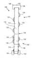
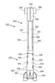
図1~6は、本発明の外科用クリップ100の第1の実施形態を示している。図示のように、外科用クリップ100は、近位端部100Aと遠位端部100Bとを有することができる。外科用クリップ100は、近位端部102A及び遠位端部102Bを有する第1の脚部材102と、近位端部104A及び遠位端部104Bを有する第2の脚部材104とを更に含むことができる。第1及び第2の脚部材102、104は、ヒンジ部分106により近位端部102A、104Aで一体的に連結することができる。 1-6 illustrate a first embodiment of a
従来の慣例に従って、本明細書で用いる場合、本明細書で特に明記しない限り、用語「近位部分」は、使用することが意図された時にデバイスを扱う又は操作する医療関係者に一般的により近いデバイス又はその構成要素の特定の部分を指し、用語「遠位部分」は、近位部分とは反対側のデバイス又はその構成要素の特定の部分を指す。用語「長手方向の」は、外科用クリップ100及び/又は脚部材102、104の長さに沿って、それぞれの近位端部100A、102A、104Aからそれぞれの遠位端部100B、102B、104Bまで延びる寸法を指す。更に本明細書で用いる場合、「横断」方向は、外科用クリップ100又は脚部材102、104の長手方向の長さに直交するあらゆる軸又は方向に関する。従って、用語「長さ」は、外科用クリップ100及び/又は1又は2以上の構成要素の、その長手方向に沿う寸法を指す。「高さ」又は「垂直」という用語は、外科用クリップ100及び/又は1又は2以上の構成要素の、脚部材102、104の圧縮軸に沿う寸法を指す。用語「厚さ」は、外科用クリップ100及び/又は1又は2以上の構成要素の対向する縁部間の、圧縮軸又は垂直軸に沿う寸法を指す。用語「幅」は、外科用クリップ100及び/又は1又は2以上の構成要素の、長さ及び高さに対して実質的に横断する横方向での寸法を指す。用語「凹状の」及び「凸状の」は、表面又は構成要素の外側を眺めた時に見える表面又は構成要素の湾曲を指す。書面の開示全体を通して、同様の用語を使用する。 In accordance with conventional practice, as used herein, unless otherwise specified herein, the term "proximal portion" generally refers to The term "distal portion" refers to a particular portion of the device or its components that is proximal, and the term "distal portion" refers to a particular portion of the device or its components that is opposite the proximal portion. The term "longitudinal" means along the length of
第1及び第2の脚部材102、104は、湾曲部分を有する表面を含むことができる。例えば、第1の脚部材102は、第1の内面108と第1の外面110とを含むことができ、第2の脚部材104は、第2の内面112と第2の外面114とを含むことができる。図1に示すように、第1の内面108は凹状の湾曲を有することができ、第1の外面110は凸状の湾曲を有することができる。第2の内面112は凸状の湾曲を有することができ、第2の外面114は、少なくとも1つの凸状の湾曲及び/又は少なくとも1つの凹状の湾曲のうちの1又は2以上を有することができる。第1の内面108の凹状湾曲及び/又は第1の外面110の凸状湾曲は、第1の脚部材102の実質的に長さ全体に亘って延びることができる。第2の内面112の凸状湾曲は、実質的に第2の脚部材104の長さ全体に亘って延びることができる。第1及び第2の内面108、112は、閉鎖形態において近接する又は接触することができる。第1及び第2の内面108、112はまた、実質的に平滑とすることができる。また、第1の脚部材102は対向する側面138、140を含むことができ、第2の脚部材104は対向する側面142、144を含むことができる。 The first and
第2の脚部材104は、第1の部分166及び第2の部分168で一体的に連結された内側部分162(例えば、内側リブ)と外側部分164(例えば、外側リブ)とを含むことができる。内側部分162は、凸状内面170と凹状外面172とを有することができる。内側部分162及び外側部分164のうちの少なくとも一方は、第1の脚部材102の厚さよりも小さな厚さを有することができる。内側部分162及び/又は外側部分164のより小さな厚さは、第2の脚部材104に関して、第1の脚部材102よりも高い可撓性を提供することができる。一部の実施形態では、内側部分162は外側部分164よりも大きな厚さを有することができ、及び/又は外側部分164は内側部分162よりも大きな長さを有することができる。内側部分162の内面170は、第2の内面112の少なくとも一部分を形成することができ、外側部分164の外面は、外科用クリップ100の第1の外面114の少なくとも一部分を形成することができる。 The
内側部分162は、様々な形状、サイズ、位置、及び/又は剛性の組織に圧力を適切に分散させるために、その長さの少なくとも一部に沿って垂直な圧縮方向に弾性的に撓むように構成することができる。内側部分162は、付加的に又は代替的に、組織の位置決めに基づいてその長さの何れかの部分に沿って撓むことができる。例えば、組織がヒンジ部分106に近接して位置決めされる場合、内側部分162の近位部分は、組織を収容するために撓むことができる。しかしながら、組織が係止機構に近接して位置決めされる場合、内側部分162の遠位部分が撓むことができる。その意味で、外科用クリップ100は、係止機構及び/又はヒンジ部分106の何れかへの組織の近接に起因する応力局在化を低減することができる。内側部分162の弾性圧縮はまた、組織が壊死し収縮しても、閉鎖及び/又は係止形態で組織に連続的な結紮圧力を提供することができる。
内側部分162と外側部分164は、第2の脚部材104の圧縮を可能にするために、第2の脚部材104の側面142、144間に延びる少なくとも1つの横断開口又はチャネル178によって分離することができる。例えば、チャネル178は、内側部分162を外側部分164に向かって弾性的に押し付けることを可能にして組織の長さに沿って荷重を分散させ、一方で外科用クリップ100内に組織をより効果的に把持及び保持することができる。チャネル178はまた、内側部分162の撓みに関する制約を軽減するために、外側部分164がより長い長さを有することを可能にする。例えば、外側部分164の長さの増加により、内側部分162が閉鎖及び/又は係止中に屈曲して平らになる時の、内側部分162の可撓性に関する制約を軽減することができる。一部の実施形態では、内側部分162、外側部分164、及び/又はチャネル178は、第2の脚部材104の長さの8分の1を超えて延びることができる。一部の実施形態では、内側部分162、外側部分164、及び/又はチャネル178は、第2の脚部材104の長さの4分の1を超えて延びることができる。一部の実施形態では、内側部分162、外側部分164、及び/又はチャネル178は、実質的に第1の脚部材102の長さ全体に亘って延びることができる。 The
内側部分162と外側部分164は、内側部分162及び外側部分164の長さに沿って、隣接する対応点の間で異なる曲率半径を有することができる。一部の実施形態では、隣接する対応点の間での内側部分162の第1の曲率半径と外側部分164の第2の曲率半径は、内側部分162及び外側部分164の長さの少なくとも半分について異なるとすることができる。一部の実施形態では、第1の曲率半径と第2の曲率半径は、内側部分162及び外側部分164の実質的に長さ全体について異なるとすることができる。内側部分162は、変曲点のない実質的に連続した曲率半径を有することができ、外側部分164は、少なくとも1つの変曲点を伴う可変な曲率半径を有することができる。外側部分の可変な曲率半径は、図5に示すように外科用クリップアプライヤ10の供給チャネル12内に位置決めされた場合に、可変な高さと垂直方向の安定性とを提供することができる。例えば、外側部分164の近位部分174は、外側部分164の遠位部分176よりも大きな高さを有することができる。一部の実施形態では、近位部分174は、凸状外面及び凹状内面を含むことができ、遠位部176は、凹状外面及び凸状内面を含むことができる。遠位部分176の凹状外面は、不規則な応力集中を軽減するために遠位部分104Bとの滑らかな移行部を提供することができる。近位部分174の凸状外面は、供給チャネル12の壁14、16との接触点を提供して、クリップアプライヤ10に対する外科用クリップ100の近位端の垂直移動を低減するために、垂直方向に突出することができる。付加的な接触点には、第1の脚部材102の外面110、第1の脚部材102のボス146、148、及び150、及び/又は第2の脚部材104のボス152、154を含めることができる。外科用クリップ100の垂直方向安定性の向上により、クリップアプライヤ10のプッシャ部材上の安定性フィンガ及び/又はクリップアプライヤ10の顎部内への外科用クリップ100の適正な装填を不要にすることができる。
チャネル178はまた、縫合糸などの細長い部材の固定点を提供することができる。例えば、外科医は、外科用クリップ100を組織(例えば、血管)に適用し、縫合糸をチャネル178に通過又はループさせ、同じ又は異なる組織内の別の箇所にその縫合糸を通して、クリップを定位置に固定することができる。チャネル178を通された縫合糸は、付加的に又は代替的に、組織を別の位置近くに固定する、及び/又は2つの組織を互いに近接させることができる。
ヒンジ部分106は、弾性的に撓むことができ、第1及び第2の脚部材102、104と一体化することができる。ヒンジ部分106は、凹状内面116と凸状外面118とを有することができる。ヒンジ部分106の凹状内面116は、第1の脚部材102の第1の内面108と、第2の脚部材104の第2の内面112とを連結することができる。ヒンジ部分106の凸状外面118は、第1の脚部材102の第1の外面110と、第2の脚部材104の第2の外面114とを連結することができる。ヒンジ部分106はまた、ヒンジ表面116、118間に位置する湾曲スロット120を含むことができ、凸状外面118よりも凹状内面116の近くに位置決めすることができる。湾曲スロット120は、ヒンジ部分106を左右に完全に貫通することができ、その両端は、それぞれ第1及び第2の脚部材102、104の近位端部102A、102B内に延びることができる。湾曲スロット120は、ヒンジ部分106に可撓性と弾力性とを付加することができるが、凹状内面116は、締め付けられた血管のあらゆる部分が湾曲スロット120内に閉じ込められるのを防ぐことができる。 The
外科用クリップ100はまた、1又は2以上の係止要素を有する係止機構を含むことができる。例えば、第1の脚部材102は、その遠位端部102Bでフック部分126に移行することができ、第2の脚部材104は、その遠位端部104Bで相補的な溝付きで尖った先端部128に移行することができる。フック部分126の遠位端部は、内方に湾曲し、ほぼヒンジ部分材106の凹状内面の方に向いているとすることができる。フック部分126は、1又は2つ以上の横断傾斜面130と、内面108と合わさって係止凹部132を定める凹状内面とを有することができる。先端部128はV字形であって、フック部分126が先端部128の周りで撓む時に傾斜面130を受け入れるように構成されたスロットを定めることができる。フック部分126と先端部128は、係合して係止機構を形成することができる。例えば、係止凹部132は、血管又は他の組織の周りに固定された状態とすることのできる閉鎖形態(例えば、図6)に外科用クリップ100を圧縮する過程で先端部材128と係合することができる。
脚部材102、104は、クリップアプライヤ10の顎部と係合するために、その長さに沿って1又は2以上のボスを含むことができる。例えば、第1の脚部材102は、その遠位端部102Bに隣接してフック部分126のすぐ内方にある対向側面138、140の各々に対して垂直に突出するボス146、148を含むことができる。外科用クリップ100の図示する例では、ボス146、148は円柱形であって、第1の脚部材102の第1の外面110を越えて外方に突出することができる。ボス146、148はまた、ブリッジ区画150で互いに連結させることができる。第2の脚部材104も、その遠位端部104Bにボス152、154を含むことができる。ボス152、154は円柱状であり、第2の脚部材104の対向側面142、144の各々に対して垂直に突き出て、先端部128の尖端を越えて長手方向前方に延びることができる。クリップアプライヤ10の顎部は、ボス146、148、150、152、154と係合し、脚部材102、104をヒンジ部分106の周りに枢動させ、外科用クリップ100を圧縮して血管周りの閉鎖及び/又は係止形態にすることができる。 The
更に図1~6の実施形態に示すように、外科用クリップ100は、第1の脚部材102上に位置決めされた少なくとも1つの第1の歯部134と、第2の脚部材104上に位置決めされた少なくとも1つの第2の歯部136とを含むことができる。歯部134、136は、組織と係合する時に歯部134、136が実質的に撓まないように、実質的に剛性とすることができる。歯部134、136は、外科用クリップ100に対して外側寄りに位置決めすることができる。本明細書で使用する場合、用語「外側寄りの」は、外科用クリップ100の1又は2以上の外部側面上の歯部134、136の位置決めを指すものとする。例えば、歯部134、136は、側面138~144のうちの1つに取り付けられ、そこから内面108、112のうちの1又は2以上の横方向に延びることができる。例えば、歯部134、136は、側面138~144の少なくとも1つに対して実質的に平行に、及び/又は内面108、112の少なくとも1つに対して実質的に垂直に延びることができる。従って、歯部134、136を、対向する内面108、112との衝突を避けるように、且つ対向する脚部材102、104の側面138~144に沿って位置決めして、外科用クリップ100が最小限の隙間で又は隙間なしで閉じることを可能にし、小血管の効果的な閉鎖を確実にすることができる。内面108、112は、歯部を持たず、脚部材102、104の近位端部102A、104Bから遠位端部102B、104Bまで延びる実質的に平滑な表面を備えることができる。歯部134、136は、脚部材102、104の内面108、112の少なくとも一方の片側又は両側に位置決めすることができる。外側寄り歯部134、136は、より大きく、組織との相互作用においてより効果的にすることができる。例えば、歯部134、136のより大きなサイズによって、組織保持を改善し、組織が外科用クリップから滑り出るのを防ぐことができる。歯部134、136は、十分に離間して配置され、隣接する歯134、136の間に組織を挟まないとすることができる。歯部134、136は更に、成型が容易で、クリップアプライヤと干渉しないようにすることができる。歯部134、136は、本明細書で述べるように、様々な構成を有することができる。 As further shown in the embodiments of FIGS. 1-6,
図1~図6に示すように、歯部134、136は、凸状の遠位部分180と凹状の近位部分182(例えば、切欠き)とを含むことができる。凹状部分182は、歯部134、136の近位表面の約90°に広がることができる。凹状部分182は、組織を受け入れて組織が外科用クリップ100から遠位方向に滑るのを防ぐように構成することができる。凸状部分180及び凹状部分182は、外科用クリップ100で圧迫された組織への外傷を減らすことができる。歯部134、136の凸状部分は、丸形、円盤状、円形、球形、卵形、楕円形、球根状、環状、及び/又は円環を含めて、多くの形状を有することができることが企図される。また、凹状部分は、丸形、円形、球形、卵形、楕円形、U字形、L字形、及び/又はV字形を含めて、幾つもの形状にできると考えられる。歯部134、136は更に、その片側又は両側に実質的に平坦な側面を含むことができる。実質的に平坦な側面184は、内面108、112の近接又は接触を容易にして隣接組織への外傷を減らすことができる。 As shown in FIGS. 1-6, the
図6に示すように、外科用クリップ100は、第1の内面108と第2の内面112との間に最小限の隙間で又は隙間なしで閉じるように構成することができる。例えば、外科用クリップ100が閉じる時に、第1の歯部134は、第2の内面112を越えて側面142、144の少なくとも一方に沿って延びることができ、第2の歯部134は、第1の内面108を越えて側面138、140の少なくとも一方沿って延びることができる。従って、歯部134、136は、それぞれの内面108、112との衝突を避けることができるので、歯134、136に遮られることなく、組織を内面108、112で直接圧迫することができる。歯部134、136が外科用クリップ100の同じ側に位置決めされる場合には、歯部134、136を交互配置にして、干渉を減らすことができる。この閉鎖形態及び/又は係止形態は、より小さな血管のより小さな組織の圧迫を強化することができ、一方で第2の脚部材104の内面112は、血管組織を収容するために弾性的に撓むことができる。 As shown in FIG. 6, the
外科用クリップ100は更に、例えば腎部分切除中に、縫合糸を留めるように構成することができる。外科医は、組織の一部、例えば腎臓の上半分/下半分を切り離すために腎臓の一部に針で縫合糸を通す場合がある。外科医は、縫合糸の上で外科用クリップ100を閉じ、組織に対して外科用クリップ100を滑らせることができる。その後で、外科医は、縫合糸が組織を貫いて引っ張ることなく、或いは保持用結び目を作らずに、組織の縫合を続けることができる。歯部134、136は、締付圧力が低下する場合のある近位端部100A又は遠位端部100Bに向かって縫合糸を長手方向に滑らすことなく、縫合糸を外科用クリップ100の中央に保持するように構成することができる。歯部134、136のサイズを大きくすることで、縫合糸の保持力を増加させることができる。
図1~6は、第1及び第2の脚部材102、104の両側に位置決めされた歯部134、136を示している。例えば、外科用クリップ100は、図1~6に示すように、第1及び第2の脚部材の各側に2つの大きな歯134、136を含むことができる。しかしながら、歯部134、136の別の数及び構成が考えられる。歯部134、136は、脚部材102、104の少なくとも一方の片側にだけ位置決めすることができる。例えば、歯部134、136は、各脚部材102、104の同じ側にだけ(例えば、図7~10に示すように)、或いは脚部材102、104の反対側にだけ(例えば、図11に示すように)位置決めすることができる。一部の実施形態では、歯部は、脚部材102、104の一方にだけ位置決めすることができる。例えば、第1の脚部材102は、(図1~6に示すように)第1の歯部134を含むことができ、第2の脚部材104は歯部を持たなくてもよい。別の例では、第1の脚部材102は歯部を持たなくてもよく、第2の脚部材は、(図1~図6に示すように)第2の歯部136を含むことができる。上記の例の各々において、歯部134、136は、図1~6に更に示すように、それぞれの脚部材102、104の側面間を交互に繰り返すことができる。更に、歯部134、136は、図12~20の1又は2以上に示すような、異なる構成を有することができると考えられる。 1-6
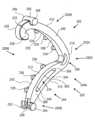
図7~10は、本発明の外科用クリップの第2の実施形態200を示す。外科用クリップ200は、外科用クリップ100と同様の特徴を有することができ、図7~10に同様に表すことができる。簡潔にするため、外科用クリップ100と同様の特徴は、外科用クリップ300に関して説明しない場合がある。 7-10 illustrate a
図示するように、外科用クリップ200は、ヒンジ部分206によって接続された第1の脚部材202と第2の脚部材204とを含むことができる。第1及び第2の脚部材202、204は、湾曲部分を有する表面を含むことができる。例えば、第1の脚部材202は、第1の内面208と第1の外面210とを含むことができ、第2の脚部材204は、第2の内面212と第2の外面214とを含むことができる。図7に示すように、第1の内面208は凹状の湾曲を有することができ、第1の外面210は凸状の湾曲を有することができる。第2の内面212は凸状の湾曲を有することができ、第2の外面214は凹状の湾曲を有することができる。第1の内面208の凹状湾曲及び/又は第1の外面210の凸状湾曲は、第1の脚部材202の実質的に長さ全体に亘って延びることができる。第2の内面212の凸状湾曲及び/又は第2の外面214の凹状湾曲は、実質的に第2の脚部材204の全長に亘って延びることができる。第1及び第2の内面208、212は、閉鎖形態において近接する又は接触することができる。第1及び第2の内面208、212は、実質的に平滑とすることができる。また、第1の脚部材202は対向する側面238、240を含むことができ、第2の脚部材204は対向する側面242、244を含むことができる。 As shown,
図7~10に図示するように、第2の脚部材204は、第1の部分266及び第2の部分268で一体的に連結された内側部分262(例えば、内側リブ)と外側部分264(例えば、外側リブ)とを含むことができる。内側部分262は、凸状内面270と凹状外面272とを有することができる。外側部分264は、凸状内面274と凹状外面276とを有することができる。内側部分262と外側部分264は、内側部分262及び外側部分264の隣接した対応点の間で異なる曲率半径を有することができる。一部の実施形態では、内側部分262の第1の曲率半径と外側部分264の第2の曲率半径は、内側部分262及び外側部分264の長さの少なくとも半分について異なるとすることができる。一部の実施形態では、第1の曲率半径と第2の曲率半径は、内側部分262及び外側部分264の実質的に長さ全体について異なるとすることができる。内側部分262は外側部分よりも小さな曲率半径を有することができ、内側部分262をより凸状にする。一部の実施形態では、内側部分262は、第1の脚部材202よりも小さな曲率半径を有することができるので、組織がない場合でも閉鎖形態及び/又は係止形態に圧縮することができる。内側部分262及び/又は外側部分264は、第1の脚部材202の厚さよりも小さな厚さを有することができ、第2の脚部材204の可撓性及び/又は可圧縮性を増大させる。内側部分262と外側部分264は、本明細書で説明するように、少なくとも1つの横断開口又はチャネル278によって分離することができる。外科用クリップ200は、上記で更に説明したように、縫合糸を固定する及び/又は留めるように構成することができる。 As illustrated in FIGS. 7-10, the
第1及び第2の脚部材202、204は、ヒンジ部分206によって近位端部202A、202Bで一体的に連結することができる。外科用クリップ200はまた、1又は2以上の係止要素を有する係止機構を含むことができる。例えば、第1の脚部材202は、その遠位端部202Bでフック部分226に移行することができ、第2の脚部材204は、その遠位端部204Bで相補的な溝付きで尖った先端部228に移行することができる。脚部材202、204は更に、クリップアプライヤ10の顎部と係合するために、その長さに沿って1又は2以上のボスを含むことができる。例えば、第1の脚部材202は、対向側面238、240の各々に対して垂直に突き出るボス246、248を含むことができ、第2の脚部材204は、対向側面242、244の各々に対して垂直に突き出るボス252、254を含むことができる。ボス246、248はまた、ブリッジ区画250で互いに連結させることができる。 The first and
更に図7~10に示すように、外科用クリップ200はまた、第1の脚部材202の側面に取り付けられた少なくとも1つの第1の歯部234と、第2の脚部材204の同じ側に取り付けられた少なくとも1つの第2の歯部236とを含むことができる。例えば、第1の歯部234は、側面238に取り付けられてそこから延びることができ、第2の歯部236は、側面238と実質的に平行な側面242に取り付けられてそこから延びることができる。従って、第1の歯部234と第2の歯部236は、外科用クリップ200の同じ側(例えば、側面238、242)に位置決めすることができ、外科用クリップ200の反対側(例えば、側面240、244)には歯がないとすることができる。外科用クリップ200の同じ側に歯部234、236を位置決めすることにより、より傷付きやすい組織に誘発される外傷を減らすことができる。歯部234、236は、前述のように、外科用クリップ100と同様に外側寄りに位置決めされる、及び/又は内面208、212の間に最小限の隙間で又は隙間なしで閉じられるとすることができる。歯部234、236はまた、更に前述したように幾つもの形状を有することができる。 As further shown in FIGS. 7-10, the
一部の実施形態では、歯部は、脚部材202、204の一方にだけ位置決めすることができる。例えば、第1の脚部材202は、第1の歯部234を含むことができ(図7~10に示すように)、第2の脚部材204は歯部を持たないとすることができる。別の例では、第1の脚部材202は歯部を持たなくてもよく、第2の脚部材は第2の歯部236を含むことができる(図7~10に示すように)。上記の例の各々において、歯部234、236は、それぞれの脚部材202、204の側面間を交互に繰り返すことができる。 In some embodiments, the teeth can be positioned on only one of the
図11は、本発明の外科用クリップの第3の実施形態300を示す。外科用クリップ300は、外科用クリップ100、200の少なくとも一方と同様の特徴を有することができ、図11に同様に表すことができる。簡潔にするため、外科用クリップ100、200の少なくとも一方と同様の特徴は、外科用クリップ300に関して説明しない場合がある。 FIG. 11 shows a
図示するように、外科用クリップ300は、ヒンジ部分306によって接続された第1の脚部材302と第2の脚部材304とを含むことができる。第1及び第2の脚部材302、304は、湾曲部分を有する表面を含むことができる。例えば、第1の脚部材302は、第1の内面308と第1の外面310とを含むことができ、第2の脚部材304は、第2の内面312と第2の外面314とを含むことができる。第1の内面308は凹状の湾曲を有することができ、第1の外面310は凸状の湾曲を有することができる。第2の内面312は凸状の湾曲を有することができ、第2の外面314は凹状の湾曲を有することができる。第1の内面308の凹状湾曲及び/又は第1の外面310の凸状湾曲は、第1の脚部材302の実質的に長さ全体に亘って延びることができる。第2の内面312の凸状湾曲及び/又は第2の外面314の凹状湾曲は、実質的に第2の脚部材304の長さ全体に亘って延びることができる。第1及び第2の内面308、312は、閉鎖形態において近接する又は接触することができる。第1及び第2の内面308、312は、実質的に平滑とすることができる。また、第1の脚部材302は対向する側面338、340を含むことができ、第2の脚部材304は対向する側面342、344を含むことができる。 As shown,
第2の脚部材304は、第1の部分366及び第2の部分368で一体的に連結された内側部分362(例えば、内側リブ)と外側部分364(例えば、外側リブ)とを含むことができる。内側部分362は、凸状内面370と凹状外面372とを有することができる。外側部分364は、凸状内面と凹状外面とを有することができる。内側部分362と外側部分364は、内側部分362及び外側部分364の長さに沿って、隣接した対応点の間で異なる曲率半径を有することができる。一部の実施形態では、内側部分362の第1の曲率半径と外側部分364の第2の曲率半径は、内側部分362及び外側部分364の長さの少なくとも半分について異なるとすることができる。一部の実施形態では、第1の曲率半径と第2の曲率半径は、内側部分362及び外側部分364の実質的に長さ全体について異なるとすることができる。内側部分362は外側部分よりも小さな曲率半径を有することができ、内側部分362をより凸状にする。一部の実施形態では、内側部分362は、第1の脚部材302よりも小さな曲率半径を有することができるので、組織がない場合でも閉鎖形態及び/又は係止形態に圧縮することができる。内側部分362及び/又は外側部分364は、第1の脚部材302の厚さよりも小さな厚さを有することができ、第2の脚部材304の可撓性及び/又は可圧縮性を増大させる。内側部分362と外側部分364は、前述のように、少なくとも1つの横断開口又はチャネル378によって分離することができる。外科用クリップ300は、更に前述したように、縫合糸を固定する及び/又は留めるように構成することができる。 The
外科用クリップ300はまた、1又は2以上の係止要素を有する係止機構を含むことができる。例えば、第1の脚部材302は、その遠位端部302Bでフック部分326に移行することができ、第2の脚部材304は、その遠位端部304Bで相補的な溝付きで尖った先端部328に移行することができる。脚部材302、304は更に、クリップアプライヤ10の顎部と係合するために、その長さに沿って1又は2以上のボスを含むことができる。例えば、第1の脚部材302は、対向側面338、340の各々に対して垂直に突き出るボス346、348を含むことができ、第2の脚部材304は、対向側面342、344の各々に対して垂直に突き出るボス352、354を含むことができる。ボス346、348はまた、ブリッジ区画350で互いに連結させることができる。
更に図11に示すように、外科用クリップ300は、第1の脚部材302の第1の側に位置決めされた少なくとも1つの第1の歯部334と、第2の脚部材304の、第1の側とは反対の第2の側に位置決めされた少なくとも1つの第2の歯部336とを含むことができる。例えば、第1の歯部334は、側面338から延びることができ、第2の歯部336は、側面344から延びることができる。従って、歯部334、336は、外科用クリップ300の反対側に位置決めすることができ、第1の脚部材302の側面340と第2の脚部材304の側面342には歯部がないとすることができる。外科用クリップ300の反対側に歯部334、336を位置決めすることにより、組織との噛み合わせを強化し、一方で歯部の数と組織の外傷とを減らすことができる。歯部234、236は、前述のように、外科用クリップ100と同様に外側寄りに位置決めすることができる。歯部234、236はまた、更に前述したように幾つもの形状を有することができる。 As further shown in FIG. 11, the
図12は、本発明の外科用クリップの第4の実施形態400を示す。外科用クリップ400は、外科用クリップ100~300の少なくとも1つと同様の1又は2以上の特徴を含むことができ、図12に同様に表すことができる。簡潔にするため、外科用クリップ100~300の少なくとも1つに関する特徴と同様の特徴は、外科用クリップ400に関して説明しない場合がある。 FIG. 12 shows a
外科用クリップ400は、ヒンジ部分406によって接続された第1の脚部材402と第2の脚部材404とを含むことができる。第1及び第2の脚部材402、404は、湾曲部分を有する表面を含むことができる。例えば、第1の脚部材402は、第1の内面408と第1の外面410とを含むことができ、第2の脚部材404は、第2の内面412と第2の外面414とを含むことができる。第1の内面408は凹状の湾曲を有することができ、第1の外面410は凸状の湾曲を有することができる。第2の内面412は凸状の湾曲を有することができ、第2の外面414は凹状の湾曲を有することができる。第1の内面408の凹状湾曲及び/又は第1の外面410の凸状湾曲は、第1の脚部材402の実質的に長さ全体に亘って延びることができる。第2の内面412の凸状湾曲及び/又は第2の外面414の凹状湾曲は、実質的に第2の脚部材404の長さ全体に亘って延びることができる。第1及び第2の内面408、412は、閉鎖形態において近接する又は接触することができる。第1及び第2の内面408、412は、実質的に平滑とすることができる。また、第1の脚部材402は対向する側面438、440を含むことができ、第2の脚部材404は対向する側面442、444を含むことができる。
第2の脚部材404は、第1の部分466及び第2の部分468で一体的に連結された内側部分462(例えば、内側リブ)と外側部分464(例えば、外側リブ)とを含むことができる。内側部分462は、凸状内面470と凹状外面472とを有することができる。外側部分464は、凸状内面と凹状外面とを有することができる。内側部分462と外側部分464は、内側部分462及び外側部分464の長さに沿って、隣接した対応点の間で異なる曲率半径を有することができる。一部の実施形態では、内側部分462の第1の曲率半径と外側部分464の第2の曲率半径は、内側部分462及び外側部分464の長さの少なくとも半分について異なるとすることができる。一部の実施形態では、第1の曲率半径と第2の曲率半径は、内側部分462及び外側部分464の実質的に長さ全体について異なるとすることができる。内側部分462は外側部分464よりも小さな曲率半径を有することができ、内側部分462をより凸状にする。一部の実施形態では、内側部分462は、第1の脚部材402よりも小さな曲率半径を有することができるので、組織がない場合でも閉鎖形態及び/又は係止形態に圧縮することができる。内側部分462及び/又は外側部分464は、第1の脚部材402の厚さよりも小さな厚さを有することができ、第2の脚部材404の可撓性及び/又は可圧縮性を増大させる。内側部分462と外側部分464は、前述のように、少なくとも1つの横断開口又はチャネル478によって分離することができる。外科用クリップ400は、更に前述したように、縫合糸を固定する及び/又は留めるように構成することができる。 The
外科用クリップ400はまた、1又は2以上の係止要素を有する係止機構を含むことができる。例えば、第1の脚部材402は、その遠位端部402Bでフック部分426に移行することができ、第2の脚部材404は、その遠位端部404Bで相補的な溝付きで尖った先端部428に移行することができる。脚部材402、404は更に、クリップアプライヤ10の顎部と係合するために、その長さに沿って1又は2以上のボスを含むことができる。例えば、第1の脚部材402は、対向側面438、440の各々に対して垂直に突き出るボス446、448を含むことができ、第2の脚部材404は、対向側面442、444の各々に対して垂直に突き出るボス452、454を含むことができる。第1の脚部材402のボス446、448は、ブリッジ区画450で互いに連結させることができる。
更に図12に示すように、外科用クリップ400は、非外傷性の組織クランプ面を提供する凸状部材を備えた、少なくとも1つの第1の歯部434及び/又は少なくとも1つの第2の歯部436を含むことができる。一部の実施形態では、凸状部材は、約180°よりも大きい凸状区分を含むことができる。一部の実施形態では、凸状部材は、約270°よりも大きい凸状区分を含むことができる。一部の実施形態では、凸状部材は、約360°の凸状区分を含むことができる。 1又は2以上の凸状部材は、丸形、円盤形状、円形、球形、卵形、楕円形、球根状、環状、及び/又は円環を含めて、幾つもの形状にできると考えられる。 As further shown in FIG. 12, the
更に図12に示すように、第1の歯部434は、第1の脚部材402の第1の側面438から第1の内面408の横方向に延びることができ、1又は2以上の第2の歯部435は、第2の脚部材404の第2の側面442から第2の内面512の横方向に延びることができる。側面438、442は、脚部材402、404の同じ側にあるとすることができる。代わりに一部の実施形態では、歯部434、436は、例えば図1~6に示すように、脚部材402、404の少なくとも一方の両側に位置決めすることができる。一部の実施形態では、歯部434、436は、例えば図11に示すように、脚部材402、404の反対側にだけ位置決めすることができる。歯部434、436の円形形態は、組織への外傷を更に一層減らすことができる。歯部434、436は、前述のように、外科用クリップ100と同様に外側寄りに位置決めすることができる。 As further shown in FIG. 12, the
一部の実施形態では、歯部は、脚部材402、404の一方にだけ位置決めすることができる。例えば、第1の脚部材402は、第1の歯部434を含むことができ、第2の脚部材404は歯部を持たないとすることができる。別の例では、第1の脚部材402は歯部を持たなくてもよく、第2の脚部材は第2の歯部436を含むことができる。上記の例の各々において、歯部434、436は、前述のようにそれぞれの脚部材402、404の側面間を交互に繰り返すことができる。 In some embodiments, the teeth can be positioned on only one of the
図13は、本発明の外科用クリップの第5の実施形態500を示す。外科用クリップ500は、外科用クリップ100~400の少なくとも1つと同様の1又は2以上の特徴を含むことができ、図13に同様に表すことができる。簡潔にするため、外科用クリップ100~400の少なくとも1つに関する特徴と同様の特徴は、外科用クリップ500に関して説明しない場合がある。 FIG. 13 shows a
外科用クリップ500は、ヒンジ部分506によって接続された第1の脚部材502と第2の脚部材504とを含むことができる。第1及び第2の脚部材502、504は、湾曲部分を有する表面を含むことができる。例えば、第1の脚部材502は、第1の内面508と第1の外面510とを含むことができ、第2の脚部材504は、第2の内面512と第2の外面514とを含むことができる。第1の内面508は凹状の湾曲を有することができ、第1の外面510は凸状の湾曲を有することができる。第2の内面512は凸状の湾曲を有することができ、第2の外面514は凹状の湾曲を有することができる。第1の内面508の凹状湾曲及び/又は第1の外面210の凸状湾曲は、第1の脚部材502の実質的に長さ全体に亘って延びることができる。第2の内面512の凸状湾曲及び/又は第2の外面514の凹状湾曲は、実質的に第2の脚部材504の長さ全体に亘って延びることができる。第1及び第2の内面508、512は、閉鎖形態において近接する又は接触することができる。第1及び第2の内面508、512は、実質的に平滑とすることができる。また、第1の脚部材502は対向する側面538、540を含むことができ、第2の脚部材504は対向する側面542、544を含むことができる。
第2の脚部材504は、第1の部分566及び第2の部分568で一体的に連結された内側部分562(例えば、内側リブ)と外側部分564(例えば、外側リブ)とを含むことができる。内側部分562は、凸状内面570と凹状外面572とを有することができる。外側部分564は、凸状内面と凹状外面とを有することができる。内側部分562と外側部分564は、内側部分562及び外側部分564の長さに沿って、隣接した対応点の間で異なる曲率半径を有することができる。一部の実施形態では、内側部分562の第1の曲率半径と外側部分564の第2の曲率半径は、内側部分562及び外側部分564の長さの少なくとも半分について異なるとすることができる。一部の実施形態では、第1の曲率半径と第2の曲率半径は、内側部分562及び外側部分564の実質的に長さ全体について異なるとすることができる。内側部分562は外側部分よりも小さな曲率半径を有することができ、内側部分562をより凸状にする。一部の実施形態では、内側部分562は、第1の脚部材502よりも小さな曲率半径を有することができるので、組織がない場合でも閉鎖形態及び/又は係止形態に圧縮することができる。内側部分562及び/又は外側部分564は、第1の脚部材502の厚さよりも小さな厚さを有することができ、第2の脚部材504の可撓性及び/又は可圧縮性を増大させる。内側部分562と外側部分564は、前述のように、少なくとも1つの横断開口又はチャネル578によって分離することができる。外科用クリップ500は、更に前述したように、縫合糸を固定する及び/又は留めるように構成することができる。 The
外科用クリップ500はまた、1又は2以上の係止要素を有する係止機構を含むことができる。例えば、第1の脚部材502は、その遠位端部502Bでフック部分526に移行することができ、第2の脚部材504は、その遠位端部504Bで相補的な溝付きで尖った先端部528に移行することができる。脚部材502、504は更に、クリップアプライヤ10の顎部と係合するために、その長さに沿って1又は2以上のボスを含むことができる。例えば、第1の脚部材502は、対向側面538、540の各々に対して垂直に突き出るボス546、548を含むことができ、第2の脚部材504は、対向側面542、544の各々に対して垂直に突き出るボス552、554を含むことができる。第1の脚部材502のボス546、548は、ブリッジ区画550で互いに連結させることができる。
更に示すように、外科用クリップ500は、少なくとも1つの第1の歯部534及び/又は少なくとも1つの第2の歯部536を含むことができる。歯部534、536のうちの1又は2以上は、近位側に角度付けされた突出部を備えることができる。近位側に角度付けされた突出部は、組織保持を改善し、外科用クリップ500を閉じる時に組織がクリップ500から遠位側に滑り出る(例えば、「ウォーターメロン・シーディング」効果)のを防ぐことができる。突出部の先端は比較的鋭利である、或いは組織への外傷を軽減するために丸くすることができる。 As further shown,
更に前述したように、第1の歯部534は、第1の脚部材502の第1の側面538から第1の内面508の横方向に延びることができ、1又は2以上の第2の歯部535は、第2の脚部材504の第2の側面544から第2の内面512の横方向に延びることができる。一部の実施形態では、歯部534、536は、例えば図1~6に示すように、脚部材502、504の少なくとも一方の両側に位置決めすることができる。一部の実施形態では、歯部534、536は、例えば図7~10に示すように、脚部材502、504の同じ側にだけ位置決めすることができる。一部の実施形態では、歯部534、536は、図11に示すように、脚部材502、504の反対側にだけ位置決めすることができる。歯部534、536は、前述のように、外科用クリップ100と同様に外側寄りに位置決めすることができる。 Further, as described above, the
一部の実施形態では、歯部は、脚部材502、504の一方にだけ位置決めすることができる。例えば、第1の脚部材502は、第1の歯部534を含むことができ、第2の脚部材504は歯部を持たないとすることができる。別の例では、第1の脚部材502は歯部を持たなくてもよく、第2の脚部材504は第2の歯部536を含むことができる。上記の例の各々において、歯部534、536は、前述のようにそれぞれの脚部材502、504の側面間を交互に繰り返すことができる。 In some embodiments, the teeth can be positioned on only one of the
図14は、本発明の外科用クリップの第6の実施形態600を示す。外科用クリップ600は、外科用クリップ100~500のうちの少なくとも1つと同様の1又は2以上の特徴を含むことができ、図13に同様に表すことができる。簡潔にするため、外科用クリップ100~500の少なくとも1つに関する特徴と同様の特徴は、外科用クリップ600に関して説明しない場合がある。 FIG. 14 shows a
外科用クリップ600は、ヒンジ部分606によって接続された第1の脚部材602と第2の脚部材604とを含むことができる。第1及び第2の脚部材602、604は、湾曲部分を有する表面を含むことができる。例えば、第1の脚部材602は、第1の内面608と第1の外面610とを含むことができ、第2の脚部材604は、第2の内面612と第2の外面614とを含むことができる。第1の内面608は凹状の湾曲を有することができ、第1の外面610は凸状の湾曲を有することができる。第2の内面612は凸状の湾曲を有することができ、第2の外面614は凹状の湾曲を有することができる。第1の内面608の凹状湾曲及び/又は第1の外面610の凸状湾曲は、第1の脚部材602の実質的に長さ全体に亘って延びることができる。第2の内面612の凸状湾曲及び/又は第2の外面614の凹状湾曲は、実質的に第2の脚部材604の長さ全体に亘って延びることができる。第1及び第2の内面608、612は、閉鎖形態において近接する又は接触することができる。第1及び第2の内面608、612は、実質的に平滑とすることができる。また、第1の脚部材602は対向する側面638、640を含むことができ、第2の脚部材604は対向する側面642、644を含むことができる。
第2の脚部材604は、第1の部分666及び第2の部分668で一体的に連結された内側部分662(例えば、内側リブ)と外側部分664(例えば、外側リブ)とを含むことができる。内側部分662は、凸状内面670と凹状外面672とを有することができる。外側部分664は、凸状内面と凹状外面とを有することができる。内側部分662と外側部分664は、内側部分662及び外側部分664の長さに沿って、隣接した対応点の間で異なる曲率半径を有することができる。一部の実施形態では、内側部分662の第1の曲率半径と外側部分664の第2の曲率半径は、内側部分662及び外側部分664の長さの少なくとも半分について異なるとすることができる。一部の実施形態では、第1の曲率半径と第2の曲率半径は、内側部分662及び外側部分664の実質的に長さ全体について異なるとすることができる。内側部分662は外側部分よりも小さな曲率半径を有することができ、内側部分662をより凸状にする。一部の実施形態では、内側部分662は、第1の脚部材602よりも小さな曲率半径を有することができるので、組織がない場合でも閉鎖形態及び/又は係止形態に圧縮することができる。内側部分662及び/又は外側部分664は、第1の脚部材602の厚さよりも小さな厚さを有することができ、第2の脚部材604の可撓性及び/又は可圧縮性を増大させる。内側部分662と外側部分664は、前述のように、少なくとも1つの横断開口又はチャネル678によって分離することができる。外科用クリップ600は、更に前述したように、縫合糸を固定する及び/又は留めるように構成することができる。 The
外科用クリップ600はまた、1又は2以上の係止要素を有する係止機構を含むことができる。例えば、第1の脚部材602は、その遠位端部602Bでフック部分626に移行することができ、第2の脚部材604は、その遠位端部604Bで相補的な溝付きで尖った先端部628に移行することができる。脚部材602、604は更に、クリップアプライヤ10の顎部と係合するために、その長さに沿って1又は2以上のボスを含むことができる。例えば、第1の脚部材602は、対向側面638、640の各々に対して垂直に突き出るボス646、648を含むことができ、第2の脚部材604は、対向側面642、644の各々に対して垂直に突き出るボス652、654を含むことができる。第1の脚部材602のボス646、648は、ブリッジ区画650で互いに連結させることができる。
更に図14示すように、外科用クリップ600は、1又は2以上の第1の歯部634、及び/又は複数の突起を有する1又は2以上の第2の歯部636を含むことができる。更に前述したように、第1の歯部634は、第1の脚部材602の第1の側面638から第1の内面608の横方向に延びることができ、1又は2以上の第2の歯部635は、第2の脚部材604の第2の側面644から第2の内面612の横方向に延びることができる。一部の実施形態では、歯部634、636は、例えば図1~6に示すように、脚部材602、604の少なくとも一方の両側に位置決めすることができる。一部の実施形態では、歯部634、636は、例えば図7~10に示すように、脚部材602、604の同じ側にだけ位置決めすることができる。一部の実施形態では、歯部634、636は、図11に示すように、脚部材602、604の反対側にだけ位置決めすることができる。歯部634、636は、前述のように、外科用クリップ100と同様に外側寄りに位置決めすることができる。 As further shown in FIG. 14, the
一部の実施形態では、歯部は、脚部材602、604の一方にだけ位置決めすることができる。例えば、第1の脚部材602は、第1の歯部634を含むことができ、第2の脚部材604は歯部を持たないとすることができる。別の例では、第1の脚部材602は歯部を持たなくてもよく、第2の脚部材604は第2の歯部636を含むことができる。上記の例の各々において、歯部634、636は、前述のようにそれぞれの脚部材602、604の側面間を交互に繰り返すことができる。 In some embodiments, the teeth can be positioned on only one of the
図15及び16は、本発明の外科用クリップの第7の実施形態700を示す。外科用クリップ700は、外科用クリップ100~600のうちの少なくとも1つと同様の1又は2以上の特徴を含むことができ、図15及び16に同様に表すことができる。簡潔にするため、外科用クリップ100~600の少なくとも1つに関する特徴と同様の特徴は、外科用クリップ700に関して説明しない場合がある。 15 and 16 illustrate a
外科用クリップ700は、ヒンジ部分706によって接続された第1の脚部材702と第2の脚部材704とを含むことができる。第1及び第2の脚部材702、704は、湾曲部分を有する表面を含むことができる。例えば、第1の脚部材702は、第1の内面608と第1の外面710とを含むことができ、第2の脚部材704は、第2の内面712と第2の外面714とを含むことができる。第1の内面708は凹状の湾曲を有することができ、第1の外面710は凸状の湾曲を有することができる。第2の内面712は凸状の湾曲を有することができ、第2の外面714は凹状の湾曲を有することができる。第1の内面708の凹状湾曲及び/又は第1の外面710の凸状湾曲は、第1の脚部材702の実質的に長さ全体に亘って延びることができる。第2の内面712の凸状湾曲及び/又は第2の外面714の凹状湾曲は、実質的に第2の脚部材704の長さ全体に亘って延びることができる。第1及び第2の内面708、712は、閉鎖形態において近接する又は接触することができる。第1及び第2の内面708、712は、実質的に平滑とすることができる。また、第1の脚部材702は対向する側面738、740を含むことができ、第2の脚部材704は対向する側面742、744を含むことができる。
第2の脚部材704は、第1の部分766及び第2の部分768で一体的に連結された内側部分762(例えば、内側リブ)と外側部分764(例えば、外側リブ)とを含むことができる。内側部分762は、凸状内面770と凹状外面772とを有することができる。外側部分764は、凸状内面と凹状外面とを有することができる。内側部分762と外側部分764は、内側部分762及び外側部分764の長さに沿って、隣接した対応点の間で異なる曲率半径を有することができる。一部の実施形態では、内側部分762の第1の曲率半径と外側部分764の第2の曲率半径は、内側部分762及び外側部分764の長さの少なくとも半分について異なるとすることができる。一部の実施形態では、第1の曲率半径と第2の曲率半径は、内側部分762及び外側部分764の実質的に長さ全体について異なるとすることができる。内側部分762は外側部分よりも小さな曲率半径を有することができ、内側部分762をより凸状にする。一部の実施形態では、内側部分762は、第1の脚部材602よりも小さな曲率半径を有することができるので、組織がない場合でも閉鎖形態及び/又は係止形態に圧縮することができる。内側部分762及び/又は外側部分764は、第1の脚部材702の厚さよりも小さな厚さを有することができ、第2の脚部材704の可撓性及び/又は可圧縮性を増大させる。内側部分762と外側部分764は、前述のように、少なくとも1つの横断開口又はチャネル778によって分離することができる。外科用クリップ700は、更に前述したように、縫合糸を固定する及び/又は留めるように構成することができる。 The
外科用クリップ700はまた、1又は2以上の係止要素を有する係止機構を含むことができる。例えば、第1の脚部材702は、その遠位端部702Bでフック部分726に移行することができ、第2の脚部材704は、その遠位端部704Bで相補的な溝付きで尖った先端部728に移行することができる。脚部材702、704は更に、クリップアプライヤ10の顎部と係合するために、その長さに沿って1又は2以上のボスを含むことができる。例えば、第1の脚部材702は、対向側面738、740の各々に対して垂直に突き出るボス746、748を含むことができ、第2の脚部材704は、対向側面742、744の各々に対して垂直に突き出るボス752、754を含むことができる。第1の脚部材702のボス746、748は、ブリッジ区画750で互いに連結させることができる。
更に図15及び16に示すように、第1の歯部734は、第1の脚部材702上の単一の細長い歯部又は隆起とすることができ、一部の実施形態では、第1の歯部734は、近位端部702Aと遠位端部702Bの間に延びることができる。第2の歯部736は、第2の脚部材704上の単一の細長い歯部又は隆起とすることができ、一部の実施形態では、第2の歯部736は、近位端部704Aと遠位端部704Bの間に延びることができる。第1の歯部734は、第1及び第2の平坦な側面と、組織保持を改善するための1又は2以上の溝738を有する内面とを含むことができる。歯部734、736は、前述のように、外科用クリップ100と同様に外側寄りに位置決めすることができる。一部の実施形態では、脚部材702、704の一方だけが歯部を有する。例えば、第1の脚部材702は、側面上に1又は2以上の歯部734を含むことができ、第2の脚部材704は歯部を持たない。別の例では、第1の脚部材702は歯部を持たず、第2の脚部材704は、側面上に1又は2以上の第2の歯部736を含むことができる。 As further shown in FIGS. 15 and 16, the
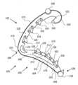
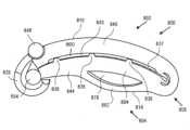
図17~20は、本発明の外科用クリップの第8の実施形態800を示している。外科用クリップ800は、外科用クリップ100~700のうちの少なくとも1つと同様の1又は2以上の特徴を含むことができ、図17~20に同様に表すことができる。簡潔にするため、外科用クリップ100~700の少なくとも1つに関する特徴と同様の特徴は、外科用クリップ800に関して説明しない場合がある。 17-20 illustrate an
図示するように、外科用クリップ800は、ヒンジ部分806によって接続された第1の脚部材802と第2の脚部材804とを含むことができる。第1及び第2の脚部材802、804は、湾曲部分を有する表面を含むことができる。例えば、第1の脚部材802は、第1の内面808と第1の外面810とを含むことができ、第2の脚部材804は、第2の内面812と第2の外面814とを含むことができる。第1の内面808は凹状の湾曲を有することができ、第1の外面810は凸状の湾曲を有することができる。第2の内面812は凸状の湾曲を有することができ、第2の外面814は、少なくとも1つの凸状湾曲及び/又は少なくとも1つの凹状湾曲のうちの1又は2以上を有することができる。第1の内面808の凹状湾曲及び/又は第1の外面810の凸状湾曲は、第1の脚部材202の実質的に長さ全体に亘って延びることができる。第2の内面812の凸状湾曲は、実質的に第2の脚部材804の長さ全体に亘って延びることができる。第1及び第2の内面808、812は、閉鎖形態において近接する又は接触することができる。第1及び第2の内面808、812は、実質的に平滑とすることができる。また、第1の脚部材802は対向する側面838、840を含むことができ、第2の脚部材804は対向する側面842、844を含むことができる。 As shown,
第2の脚部材804は、第1の部分866及び第2の部分868で一体的に連結された内側部分862(例えば、内側リブ)と外側部分864(例えば、外側リブ)とを含むことができる。内側部分862は、凸状内面870と凹状外面872とを有することができる。外側部分864は、凹状内面と凸状外面とを有することができる。内側部分862と外側部分864は、内側部分862及び外側部分864の長さに沿って、隣接した対応点の間で異なる曲率半径を有することができる。一部の実施形態では、内側部分862の第1の曲率半径と外側部分864の第2の曲率半径は、内側部分862及び外側部分864の長さの少なくとも半分について異なるとすることができる。一部の実施形態では、第1の曲率半径と第2の曲率半径は、内側部分862及び外側部分864の実質的に長さ全体について異なるとすることができる。内側部分862は外側部分864よりも大きな曲率半径を有することができ、内側部分862を外側部分864よりも少なく湾曲させる。外側部分864のより大きな湾曲により、外科用クリップ800の閉鎖/係止中の内側部分864の撓みに対する制約を軽減することができる。外面814は、内側部分862と外側部分864が繋がる第1及び第2の部分866、868で凹状の湾曲を有することができる。内側部分862及び/又は外側部分864は、第1の脚部材802の厚さよりも小さな厚さを有することができ、第2の脚部材804の可撓性及び/又は可圧縮性を増大させる。内側部分862と外側部分864は、前述のように、少なくとも1つの横断開口又はチャネル878によって分離することができる。外科用クリップ800は、更に前述したように、縫合糸を固定する及び/又は留めるように構成することができる。 The
外科用クリップ800はまた、1又は2以上の係止要素を有する係止機構を含むことができる。例えば、第1の脚部材802は、その遠位端部802Bでフック部分826に移行することができ、第2の脚部材804は、その遠位端部804Bで相補的な溝付きで尖った先端部828に移行することができる。脚部材802、804は更に、クリップアプライヤ10の顎部と係合するために、その長さに沿って1又は2以上のボスを含むことができる。例えば、第1の脚部材702は、対向側面838、840の各々に対して垂直に突き出るボス846、848を含むことができ、第2の脚部材804は、対向側面842、844の各々に対して垂直に突き出るボス852、854を含むことができる。第1の脚部材802のボス846、848は、ブリッジ区画850で互いに連結させることができる。
更に図17~20に示すように、外科用クリップ800は、第1の脚部材802及び第2の脚部材804の少なくとも一方に位置決めされた少なくとも1つの歯部836を含むことができる。例えば、第2の脚部材804は、第2の内面812上に位置決めされた少なくとも1つの歯部836を有することができ、第1の脚部材は歯部を持たないとすることができる。少なくとも1つの歯部836は、間隔を空けて、第2の内面812の少なくとも1つの側辺に位置決めすることができる。例えば、1又は2以上の歯部836は、側面842、844のうちの一方から連続的に、或いはそれと同一平面上を延びる側面を有することができる。第2の脚部材804は、第2の内面812の第1の側辺に少なくとも1つの第1の歯部836の第1列と、第2の内面812の第2の側辺に少なくとも1つの第2の歯部836の第2列とを有することができる。例えば、複数の第1の歯部836と複数の第2の歯部836は、第2の脚部材804の内面812の長さに沿って横方向に交互に繰り返すことができる。少なくとも1つの歯部836は、第2の第2の内面812に実質的に平行な、及び/又は実質的に平坦な内面を含むことができる。図20に示すように、歯部836の長さに沿う内面812の僅かな湾曲のため、歯部836は実質的に平坦であり、第1の脚部材802の長さの少なくとも一部に沿って内面812と実質的に平行であるとすることができる。少なくとも1つの歯部836は、第2の脚部材の内面から実質的に垂直に延びる第1及び第2の実質的に平坦な側面を更に有することができ、例えば、その側面の一方は側面842、844の一方と同一平面にある。少なくとも1つの歯部836はまた、第2の内面812から或る角度で延びる実質的に平坦な近位面及び遠位面を含むことができる。歯部836の近位面及び遠位面は、第2の内面812から鈍角で延びることができる。例えば、図17~20に示すような一部の実施形態では、歯部836の近位面及び遠位面は、実質的に同じ鈍角で延びて歯部836の長手方向に対称な形状を成すことができる。従って、歯部836は、鋭角を持たずに実質的に非外傷性で、十分に離間させることができるので、外科用クリップ800は、組織に不必要な外傷を引き起こす及び/又は隣接する歯部836間に組織を挟むということがない。 As further shown in FIGS. 17-20,
歯部836は、前述の「外側寄り」の歯部と同様の利点を有することができる。歯部836は外科用クリップの完全な閉鎖を妨げることがなく、より小さな血管のより効果的な閉塞を提供する。その意味で、内面808、812は実質的に平滑とすることができ、歯部836は離間して配置することができる。歯部836はまた、その歯部836をより大きく、組織との相互作用においてより効果的にすることができる。より多数の歯部836は更に、歯部836の数の削減を可能にすることができる。図17~20に示すように、外科用クリップ800は、3本の歯部836を2列有することができる。従って、歯部836は成型が容易で、クリップアプライヤと干渉しないようにすることができる。外科用クリップ800は、図20に示すように、閉鎖形態にある場合に垂直方向及び横方向に有利な低プロファイルを更に提供することができる。
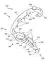
第1の脚部材802は、側面838、840のうちの1又は2以上に、第1の内面808から凹んでそれと隣接する少なくとも1つの長手方向チャネル837を有することができるので、長手方向チャネル837は、側面838、840の一方と第1の内面808との間に定められる。更に図20に示すように、少なくとも1つの長手方向チャネル837は、1又は2以上の歯部836を受け入れて、最小限の隙間で又は隙間なしで内面808、812に近接する又は接触するように構成することができる。その意味で、第1の内面808は実質的に平滑とすることができ、歯部836の間に延びる第2の内面812は実質的に平滑とすることができる。例えば、側面838を貫く第1の長手方向チャネル837は、複数の第1の歯部を受け入れることができ、側面840を貫く第2の長手方向チャネル837は、複数の第2の歯部を受け入れることができる。例えば、図示のように、長手方向チャネル837の各々は、第1の脚部材802の両側に位置決めされ、第2の脚部材804に沿って一列に離間して配置された歯部836を受け入れるように構成することができる。従って、第1の内面808は、隣接する長手方向チャネル837によって定められる内側リブ860の内面に配置することができる。リブ860の内面は、ヒンジ部材806の内面816及び/又はフック部分826の内面と連続することができる。第1の脚部材802は、内側リブ860を含む長さに沿って、内面808と外面810の間に実質的に一定の厚さを有することができる。内側リブ860は、このような小部品の製造(例えば、成型)を容易にするために、貫通するチャネル又は開口部を持たず、中実であって第1の脚部材802上に連続的に形成することができる。内側リブ860は、第1の脚部材802の実質的に長さ全体に延びることができる。従って、第1及び第2の長手方向チャネル837は個別であって、互いに接続されないとすることができる。図20に示すように、内側リブ860は、閉鎖形態では歯部836の列間に受け入れられるとすることができる。 The
一部の代替実施形態では、1又は2以上の歯部836を第1の脚部材802上に位置決めすることができ、少なくとも1つの長手方向チャネル837を第1の脚部材804上に位置決めすることができる。一部の更なる実施形態では、第1及び第2の脚部材802、804の各々は、1又は2以上の歯部836と少なくとも1つの長手方向チャネル837とを含むことができる。例えば、第1の内面808は、第1の側辺に1又は2以上の歯部836の列と、第2の側辺に長手方向チャネル837とを有することができ、第2の内面812は、第1の側辺に長手方向チャネル837と、第2の側辺に1又は2以上の歯部836の列とを備えることができる。従って、長手方向チャネル837の各々は、対向する脚部材上の1又は2以上の歯部836を受け入れることができる。 In some alternative embodiments, one or
図21~23は、本発明の外科用クリップの付加的な実施形態900~1100の側面図を示す。外科用クリップ900~1100は、内側部分と外側部分との間に延びる1又は2以上の圧縮部材990、1092、1194を含むことができる。圧縮部材990、1092、1194は、外科用クリップの全体的な圧縮強度を実質的に低下させることなく、外科用クリップに付加的な可撓性を与えることができる。一部の用途では、外科用クリップの強度は、どれだけの材料に亘って外科用クリップを閉じるかに応じて変わる可能性がある。例えば、内側部分と外側部分の隙間が十分に押し縮められなかった場合、外科用クリップは、圧縮強度が低下する可能性がある。圧縮部材990、1092、1194は、内側部分と外側部分との間の圧縮荷重分布を改善する一方で、可撓性を維持し、外科用クリップが閉じる及び/又はロックするために経る複雑な変形に適応するように構成することができる。圧縮部材990、1092、1194は、弾力性があって内側部分を支持し、外科用クリップの長さに亘って十分な圧縮を確保することができる。図1~6の第1の実施形態については示したが、圧縮部材900、1092、1194の実施形態のうちの何れか1又は2以上を本発明の外科用クリップ100~1100の実施形態の何れにも適用することができる。 21-23 illustrate side views of additional embodiments 900-1100 of surgical clips of the present invention. Surgical clips 900-1100 can include one or
図21は、本発明の外科用クリップの第9の実施形態900を示す。外科用クリップ900は、外科用クリップ100~800のうちの少なくとも1つと同様の1又は2以上の特徴を含むことができ、図21に同様に表すことができる。簡潔にするため、外科手術用クリップ100~800の少なくとも1つに関する特徴と同様の特徴は、外科手術用クリップ900に関して説明しない場合がある。 FIG. 21 shows a
図示するように、外科用クリップ900は、ヒンジ部分906によって接続された第1の脚部材902と第2の脚部材904とを含むことができる。第1及び第2の脚部材902、904は、湾曲部分を有する表面を含むことができる。例えば、第1の脚部材902は、第1の内面908と第1の外面910とを含むことができ、第2の脚部材904は、第2の内面912と第2の外面914とを含むことができる。第1の内面908は凹状の湾曲を有することができ、第1の外面910は凸状の湾曲を有することができる。第2の内面912は凸状の湾曲を有することができ、第2の外面914は、少なくとも1つの凸状湾曲及び/又は少なくとも1つの凹状湾曲のうちの1又は2以上を有することができる。第1及び第2の内面908、912は、閉鎖形態において近接する又は接触することができる。第1及び第2の内面908、912は、実質的に平滑とすることができる。 As shown,
第2の脚部材904は、第1の部分966及び第2の部分968で一体的に連結された内側部分962(例えば、内側リブ)と外側部分964(例えば、外側リブ)とを含むことができる。内側部分962と外側部分964は、内側部分962及び外側部分964の長さに沿って、隣接した対応点の間で異なる曲率半径を有することができる。一部の実施形態では、内側部分962の第1の曲率半径と外側部分964の第2の曲率半径は、内側部分962及び外側部分964の長さの少なくとも半分について異なるとすることができる。一部の実施形態では、第1の曲率半径と第2の曲率半径は、内側部分962及び外側部分964の実質的に長さ全体について異なるとすることができる。内側部分962は、変曲点のない実質的に連続した曲率半径を有することができ、外側部分964は、少なくとも1つの変曲点を伴う可変な曲率半径を有することができる。外側部分の可変な曲率半径は、図5に示すように外科用クリップアプライヤ10の供給チャネル12内に位置決めされた場合に、可変な高さと垂直方向の安定性とを提供することができる。例えば、外側部分964の近位部分974は、外側部分964の遠位部分976よりも大きな高さを有することができる。一部の実施形態では、近位部分974は、凸状外面及び凹状内面を含むことができ、遠位部976は、凹状外面及び凸状内面を含むことができる。遠位部分976の凹状外面は、不規則な応力集中を軽減するために遠位部分との滑らかな移行部を提供することができる。近位部分974の凸状外面は、供給チャネル12の壁14、16との接触点を提供して、クリップアプライヤ10に対する外科用クリップ900の近位端の垂直移動を低減するために、垂直方向に突出することができる。付加的な接触点には、第1の脚部材902の外面910、第1の脚部材902のボス946、948、及び950、及び/又は第2の脚部材904のボス952、954を含めることができる。外科用クリップ900の垂直方向安定性の向上により、クリップアプライヤ10のプッシャ部材上の安定性フィンガ及び/又はクリップアプライヤ10の顎部内への外科用クリップ900の適正な装填を、確実に不要にすることができる。 The
外科用クリップは、内側部分962と外側部分964との間に延びる1又は2以上の圧縮部材990を更に含むことができる。図示するように、圧縮部材990は、内側部分962の外面及び外側部分964の内面と一体的に形成された単一の湾曲部材を備えることができる。しかしながら、圧縮部材990は、内側部分962及び外側部分964の一方だけと一体的に形成され、内側部分962及び外側部分964の他方とは取り外し可能に接触することができる。圧縮部材990は、内側部分962の遠位部分と外側部分964の近位部分との間で、チャネル978を通って延びることができる。例えば、圧縮部材990は、外側部分964の近位部分974の凸状内面に連結される又は接触することができる。外科用クリップ900が圧縮されると、圧縮部材990は真っ直ぐになり、内側部分962及び/又は外側部分964の増大する表面積と係合し、圧縮荷重を分散させることができる。 The surgical clip can further include one or
外科用クリップ900はまた、1又は2以上の係止要素を有する係止機構を含むことができる。例えば、第1の脚部材902は、その遠位端部でフック部分926に移行することができ、第2の脚部材904は、その遠位端部で相補的な溝付きで尖った先端部928に移行することができる。脚部材902、904は更に、クリップアプライヤ10と係合するために、その長さに沿って1又は2以上のボスを含むことができる。例えば、第1の脚部材902は、対向側面938、940の各々に対して垂直に突き出るボス946、948を含むことができ、第2の脚部材904は、対向側面942、944の各々に対して垂直に突き出るボス952、954を含むことができる。第1の脚部材902のボス946、948は、ブリッジ区画950で互いに連結させることができる。更に図21の実施形態に示すように、外科用クリップ900は、第1の脚部材902上に位置決めされた少なくとも1つの第1の歯部934と、第2の脚部材904上に位置決めされた少なくとも1つの第2の歯部936とを含むことができる。歯部934、936は、実質的に剛性とすることができるので、組織と係合する時に実質的に撓まない。歯部934、936は、本明細書で述べるように、外科用クリップ900に対して外側寄りに位置決めすることができる。
図22は、本発明の外科用クリップの第10の実施形態1000を示す。外科用クリップ1000は、外科用クリップ100~900のうちの少なくとも1つと同様の1又は2以上の特徴を含むことができ、図22に同様に表すことができる。簡潔にするため、外科手術用クリップ100~900の少なくとも1つに関する特徴と同様の特徴は、外科手術用クリップ1000に関して説明しない場合がある。 FIG. 22 shows a
図示するように、外科用クリップ1000は、ヒンジ部分1006によって接続された第1の脚部材1002と第2の脚部材1004とを含むことができる。第1及び第2の脚部材1002、1004は、湾曲部分を有する表面を含むことができる。例えば、第1の脚部材1002は、第1の内面1008と第1の外面1010とを含むことができ、第2の脚部材1004は、第2の内面1012と第2の外面1014とを含むことができる。第1の内面1008は凹状の湾曲を有することができ、第1の外面1010は凸状の湾曲を有することができる。第2の内面1012は凸状の湾曲を有することができ、第2の外面1014は、少なくとも1つの凸状湾曲及び/又は少なくとも1つの凹状湾曲のうちの1又は2以上を有することができる。第1及び第2の内面1008、1012は、閉鎖形態において近接する又は接触することができる。第1及び第2の内面1008、1012は、実質的に平滑とすることができる。 As shown,
第2の脚部材1004は、少なくとも1つの横断開口又はチャネル1078によって分離され、第1の部分1066及び第2の部分1068で一体的に連結された内側部分1062(例えば、内側リブ)と外側部分1064(例えば、外側リブ)とを含むことができる。内側部分1062と外側部分1064は、内側部分1062及び外側部分1064の長さに沿って、隣接した対応点の間で異なる曲率半径を有することができる。一部の実施形態では、内側部分1062の第1の曲率半径と外側部分1064の第2の曲率半径は、内側部分1062及び外側部分1064の長さの少なくとも半分について異なるとすることができる。一部の実施形態では、第1の曲率半径と第2の曲率半径は、内側部分1062及び外側部分1064の実質的に長さ全体について異なるとすることができる。内側部分1062は、変曲点のない実質的に連続した曲率半径を有することができ、外側部分1064は、少なくとも1つの変曲点を伴う可変な曲率半径を有することができる。外側部分の可変な曲率半径は、図5に示すように外科用クリップアプライヤ10の供給チャネル12内に位置決めされた場合に、可変な高さと垂直方向の安定性とを提供することができる。例えば、外側部分1064の近位部分1074は、外側部分1064の遠位部分1076よりも大きな高さを有することができる。一部の実施形態では、近位部分1074は、凸状外面及び凹状内面を含むことができ、遠位部1076は、凹状外面及び凸状内面を含むことができる。遠位部分1076の凹状外面は、不規則な応力集中を軽減するために遠位部分との滑らかな移行部を提供することができる。近位部分1074の凸状外面は、供給チャネル12の壁14、16との接触点を提供して、クリップアプライヤ10に対する外科用クリップ1000の近位端の垂直移動を低減するために、垂直方向に突出することができる。付加的な接触点には、第1の脚部材1002の外面1010、第1の脚部材1002のボス1046、1048、及び1050、及び/又は第2の脚部材1004のボス1052、1054を含めることができる。外科用クリップ1000の垂直方向安定性の向上により、クリップアプライヤ10のプッシャ部材上の安定性フィンガ及び/又はクリップアプライヤ10の顎部内への外科用クリップ1000の適正な装填を、確実に不要にすることができる。 The
外科用クリップは、内側部分1062と外側部分1064との間に延びる1又は2以上の圧縮部材1092を更に含むことができる。図示するように、圧縮部材1092は、内側部分1062の外面及び外側部分1064の内面のうちの少なくとも一方と一体的に形成された複数の湾曲部材を備えることができる。圧縮部材1092は、内側部分1062の外面の複数の位置からチャネル978を通って遠位方向に延びることができる。外科用クリップ1000が圧縮されると、圧縮部材1092は真っ直ぐになり、内側部分1062及び/又は外側部分1064の増大する表面積と係合し、内側部分1062の長さに沿って圧縮荷重を分散させることができる。 The surgical clip can further include one or
外科用クリップ1000はまた、1又は2以上の係止要素を有する係止機構を含むことができる。例えば、第1の脚部材1002は、その遠位端部でフック部分1026に移行することができ、第2の脚部材1004は、その遠位端部で相補的な溝付きで尖った先端部1028に移行することができる。脚部材1002、1004は更に、クリップアプライヤ10と係合するために、その長さに沿って1又は2以上のボスを含むことができる。例えば、第1の脚部材902は、対向側面1038、1040の各々に対して垂直に突き出るボス1046、1048を含むことができ、第2の脚部材1004は、対向側面1042、1044の各々に対して垂直に突き出るボス1052、1054を含むことができる。第1の脚部材1002のボス1046、1048は、ブリッジ区画1050で互いに連結させることができる。更に図22の実施形態に示すように、外科用クリップ1000は、第1の脚部材1002上に位置決めされた少なくとも1つの第1の歯部1034と、第2の脚部材1004上に位置決めされた少なくとも1つの第2の歯部1036とを含むことができる。歯部1034、1036は、実質的に剛性とすることができるので、組織と係合する時に実質的に撓まない。歯部1034、1036は、本明細書で述べるように、外科用クリップ1000に対して外側寄りに位置決めすることができる。
図23は、本発明の外科用クリップの第11の実施形態1100を示す。外科用クリップ1100は、外科用クリップ100~1000のうちの少なくとも1つと同様の1又は2以上の特徴を含むことができ、図23に同様に表すことができる。簡潔にするため、外科手術用クリップ100~1000の少なくとも1つに関する特徴と同様の特徴は、外科手術用クリップ1100に関して説明しない場合がある。 FIG. 23 shows an
図示するように、外科用クリップ1100は、ヒンジ部分1106によって接続された第1の脚部材1102と第2の脚部材1104とを含むことができる。第1及び第2の脚部材1102、1104は、湾曲部分を有する表面を含むことができる。例えば、第1の脚部材1102は、第1の内面1108と第1の外面1110とを含むことができ、第2の脚部材1104は、第2の内面1112と第2の外面1114とを含むことができる。第1の内面1108は凹状の湾曲を有することができ、第1の外面1110は凸状の湾曲を有することができる。第2の内面1112は凸状の湾曲を有することができ、第2の外面1114は、少なくとも1つの凸状湾曲及び/又は少なくとも1つの凹状湾曲のうちの1又は2以上を有することができる。第1及び第2の内面1108、1112は、閉鎖形態において近接する又は接触することができる。第1及び第2の内面1108、1112は、実質的に平滑とすることができる。 As shown,
第2の脚部材1104は、少なくとも1つの横断開口又はチャネル1178によって分離され、第1の部分1166及び第2の部分1168で一体的に連結された内側部分1162(例えば、内側リブ)と外側部分1164(例えば、外側リブ)とを含むことができる。内側部分1162と外側部分1164は、内側部分1162及び外側部分1164の長さに沿って、隣接した対応点の間で異なる曲率半径を有することができる。一部の実施形態では、内側部分962の第1の曲率半径と外側部分964の第2の曲率半径は、内側部分962及び外側部分964の長さの少なくとも半分について異なるとすることができる。一部の実施形態では、第1の曲率半径と第2の曲率半径は、内側部分962及び外側部分964の実質的に長さ全体について異なるとすることができる。内側部分1162は、変曲点のない実質的に連続した曲率半径を有することができ、外側部分1164は、少なくとも1つの変曲点を伴う可変な曲率半径を有することができる。外側部分の可変な曲率半径は、図5に示すように外科用クリップアプライヤ10の供給チャネル12内に位置決めされた場合に、可変な高さと垂直方向の安定性とを提供することができる。例えば、外側部分1164の近位部分1174は、外側部分1164の遠位部分1176よりも大きな高さを有することができる。一部の実施形態では、近位部分1174は、凸状外面及び凹状内面を含むことができ、遠位部1176は、凹状外面及び凸状内面を含むことができる。遠位部分1176の凹状外面は、不規則な応力集中を軽減するために遠位部分との滑らかな移行部を提供することができる。近位部分1174の凸状外面は、供給チャネル12の壁14、16との接触点を提供して、クリップアプライヤ10に対する外科用クリップ1100の近位端の垂直移動を低減するために、垂直方向に突出することができる。付加的な接触点には、第1の脚部材1102の外面1110、第1の脚部材1102のボス1146、1148、及び1150、及び/又は第2の脚部材1104のボス1152、1154を含めることができる。外科用クリップ1100の垂直方向安定性の向上により、クリップアプライヤ10のプッシャ部材上の安定性フィンガ及び/又はクリップアプライヤ10の顎部内への外科用クリップ1100の適正な装填を、確実に不要にすることができる。 The
外科用クリップは、内側部分1162と外側部分1164との間に延びる1又は2以上の圧縮部材1192を更に含むことができる。図示するように、圧縮部材1194は、内側部分1162の外面及び外側部分1164の内面のうちの少なくとも一方と一体的に形成された複数のフック部材を備えることができる。圧縮部材1194は、内側部分962の外面の複数の位置からチャネル1178を通って遠位方向に延びることができる。外科用クリップ1100が圧縮されると、圧縮部材1194は平らになり、内側部分1162及び/又は外側部分1164の増大する表面積と係合し、内側部分1162の長さに沿って圧縮荷重を分散させることができる。 The surgical clip can further include one or more compression members 1192 extending between the
外科用クリップ1100はまた、1又は2以上の係止要素を有する係止機構を含むことができる。例えば、第1の脚部材1102は、その遠位端部でフック部分1126に移行することができ、第2の脚部材1104は、その遠位端部で相補的な溝付きで尖った先端部1128に移行することができる。脚部材1102、1104は更に、クリップアプライヤ10と係合するために、その長さに沿って1又は2以上のボスを含むことができる。例えば、第1の脚部材1102は、対向側面1138、1140の各々に対して垂直に突き出るボス1146、1148を含むことができ、第2の脚部材1104は、対向側面1142、1144の各々に対して垂直に突き出るボス1152、1154を含むことができる。第1の脚部材1102のボス1146、1148は、ブリッジ区画1150で互いに連結させることができる。更に図23の実施形態に示すように、外科用クリップ1100は、第1の脚部材1102上に位置決めされた少なくとも1つの第1の歯部1134と、第2の脚部材1104上に位置決めされた少なくとも1つの第2の歯部1136とを含むことができる。歯部1134、1136は、実質的に剛性とすることができるので、組織と係合する時に実質的に撓まない。歯部1134、1136は、本明細書で述べるように、外科用クリップ1100に対して外側寄りに位置決めすることができる。
本発明の外科用クリップの様々な実施形態は、何れかの適切なサイズで製造することができ、血管、リンパ節、神経、胆嚢管、又は心臓組織など、幾つもの組織にも適用することができる。外科用クリップの様々な実施形態は、特定の金属及びポリマなど、何れかの適切な生体適合性材料から構成することができる。しかしながら、本発明は、ポリマクリップでの実行に特に適している。従って、外科用クリップの様々な実施形態は、外科用インプラントに一般に使用されるタイプなど、適切な強度の生体適合性エンジニアリングプラスチックから形成された一体型のポリマ本体を備えることが好ましい。例示的な材料には、ホモポリマ又はコポリマポリアセタール、ポリエチレンテレフタレート(PET)、ポリブチレンテレフタレート(PBT)、ポリオキシメチレン、或いは、射出成形、押出し成形、又は別な方法で加工して同様の物品にできる同様の特性を持つ他の熱可塑性材料が含まれる。 Various embodiments of the surgical clip of the present invention can be manufactured in any suitable size and can be applied to any number of tissues, such as blood vessels, lymph nodes, nerves, cystic duct, or heart tissue. can. Various embodiments of surgical clips may be constructed from any suitable biocompatible material, including certain metals and polymers. However, the invention is particularly suited for implementation with polymeric clips. Accordingly, various embodiments of the surgical clip preferably include an integral polymer body formed from a biocompatible engineering plastic of suitable strength, such as the type commonly used in surgical implants. Exemplary materials include homopolymer or copolymer polyacetals, polyethylene terephthalate (PET), polybutylene terephthalate (PBT), polyoxymethylene, or those that can be injection molded, extruded, or otherwise processed into similar articles. Other thermoplastic materials with similar properties are included.
本発明の多くの特徴及び利点は、詳細な説明から明らかであり、従って、添付の特許請求の範囲は、本発明の真の精神及び範囲内にあるこのような本発明の特徴及び利点を全て包含するものとする。更に、数多くの変更形態及び変形形態が当業者には容易に想起されることになるので、本発明を図示し説明した正確な構造及び動作に限定することは望ましくなく、従って、全ての適切な変更形態及び等価物は、本発明に用いることができ、本発明の範囲内にある。
本発明のその他の実施態様を以下に記載する。
[実施態様1]
内面と、外面と、第1及び第2の側面とを有する第1の脚部材であって、前記第1の脚部材の内面が凹状の湾曲を有する第1の脚部材と、
内面と、外面と、第1及び第2の側面とを有する第2の脚部材であって、前記第2の脚部材の内面が凸状の湾曲を有する第2の脚部材と、
前記第2の脚部材の内面の第1の側辺から延びる少なくとも1つの第1の歯部と、
前記第1の脚部材の前記第1の側面と前記内面との間に定められた第1のチャネルと、を備え、
前記第1及び第2の脚部材は、開放形態と閉鎖形態との間を移動するように構成され、前記閉鎖形態では、前記少なくとも1つの第1の歯部が前記第1のチャネル内に受け入れられる、外科用クリップ。
[実施態様2]
前記第2の脚部材の内面の第2の側辺から延びる少なくとも1つの第2の歯部と、
前記第1の脚部材の前記第2の側面と前記内面との間に定められた第2のチャネルと、を更に備え、
前記閉鎖形態では、前記少なくとも1つの第2の歯部が前記第2のチャネル内に受け入れられる、実施態様1に記載の外科用クリップ。
[実施態様3]
前記第1のチャネルと第2のチャネルとの間に延びる中実のリブを更に備え、前記中実のリブは、前記閉鎖形態において前記少なくとも1つの第1の歯部と前記少なくとも1つの第2の歯部との間に受け入れられる、実施態様2に記載の外科用クリップ。
[実施態様4]
前記中実のリブは、貫通するチャネル又は開口部なしで、前記第1の脚部材と連続的に形成される、実施態様3に記載の外科用クリップ。
[実施態様5]
前記少なくとも1つの第1の歯部は、
実質的に平坦な内面と、
第1及び第2の実質的に平坦な側面と、
実質的に平坦な近位面と、
実質的に平坦な遠位面と、
を備える、実施態様1に記載の外科用クリップ。
[実施態様6]
前記少なくとも1つの第1の歯部の前記第1の側面は、前記第2の脚部材の前記第1の側面と同一平面にある、実施態様5に記載の外科用クリップ。
[実施態様7]
前記少なくとも1つの第1の歯部の前記近位面及び遠位面は、前記第2の脚部材の内面から鈍角で延びる、実施態様5に記載の外科用クリップ。
[実施態様8]
前記少なくとも1つの第1の歯部は、前記第2の脚部材の内面に沿って一列に離間して配置された複数の歯部を備える、実施態様1に記載の外科用クリップ。
[実施態様9]
前記第1の脚部材は歯部を有していない、実施態様1に記載の外科用クリップ。
[実施態様10]
前記第1の脚部材の遠位端部から延びるフック部材と、
前記第2の脚部材の遠位端部から延びる先端部材と、
を更に備え、
前記フック部材は、前記閉鎖形態において前記先端部材の周りに撓んで前記外科用クリップを固定するように構成される、実施態様1に記載の外科用クリップ。
[実施態様11]
前記第1の脚部材の前記第1の側面から延びる少なくとも1つのボス部材と、
前記第2の脚部材の前記第1の側面から延びる少なくとも1つのボス部材と、
を更に備える、実施態様1に記載の外科用クリップ。
[実施態様12]
前記外科用クリップは、ポリマ材料から一体的に成型される、実施態様1に記載の外科用クリップ。
[実施態様13]
前記第2の脚部材は、横断チャネルによって分離された内側部分と外側部分とを有し、前記内側部分は、前記第2の脚部材の内面を少なくとも部分的に形成し且つ第1の曲率を有し、前記外側部分は第2の曲率半径を有し、前記第2の曲率半径が前記第1の曲率半径と異なる、実施態様1に記載の外科用クリップ。
[実施態様14]
内面と、外面と、第1及び第2の側面とを有する第1の脚部材であって、前記第1の脚部材の内面が凹状の湾曲を有する第1の脚部材と、
内面と、外面と、第1及び第2の側面とを有する第2の脚部材であって、前記第2の脚部材の内面が凸状の湾曲を有する第2の脚部材と、
前記第2の脚部材の内面の第1の側辺から延びる少なくとも1つの第1の歯部と、
前記第2の脚部材の内面の第2の側辺から延びる少なくとも1つの第2の歯部と、
前記第1の脚部材の前記第1の側面と前記内面との間に定められた第1のチャネルと、
前記第1の脚部材の前記第2の側面と前記内面との間に定められた第2のチャネルと、
前記第1のチャネルと第2のチャネルとの間に延びる中実のリブと、
を備え、
前記第1及び第2の脚部材は、開放形態と閉鎖形態との間を移動するように構成され、前記閉鎖形態では、前記少なくとも1つの第1の歯部が前記第1のチャネル内に受け入れられ、前記少なくとも1つの前記第2の歯部が前記第2のチャネル内に受け入れられ、前記中実のリブが、前記少なくとも1つの第1の歯部と前記少なくとも1つの第2の歯部との間に受け入れられる、外科用クリップ。
[実施態様15]
前記中実のリブは、貫通するチャネル又は開口部なしで、前記第1の脚部材と連続的に形成される、実施態様14に記載の外科用クリップ。
[実施態様16]
前記少なくとも1つの第1の歯部と前記少なくとも1つの第2の歯部は各々、
実質的に平坦な内面と、
第1及び第2の実質的に平坦な側面と、
実質的に平坦な近位面と、
実質的に平坦な遠位面と、
を備える、実施態様14に記載の外科用クリップ。
[実施態様17]
前記第1の脚部材の遠位端部から延びるフック部材と、
前記第2の脚部材の遠位端部から延びる先端部材と、
を更に備え、
前記フック部材は、前記閉鎖形態において前記先端部材の周りに撓んで前記外科用クリップを固定するように構成される、実施態様14に記載の外科用クリップ。
[実施態様18]
前記第1の脚部材の前記第1の側面から延びる少なくとも1つのボス部材と、
前記第2の脚部材の前記第1の側面から延びる少なくとも1つのボス部材と、
を更に備える、実施態様14に記載の外科用クリップ。
[実施態様19]
前記外科用クリップは、ポリマ材料から一体的に成型される、実施態様14に記載の外科用クリップ。
[実施態様20]
前記少なくとも1つの第1の歯部は、前記第2の脚部材の内面に沿って第1の列にて離間して配置された複数の第1歯部を備え、前記少なくとも1つの第2の歯部は、前記第2の脚部材の内面に沿って第2の列にて離間して配置された複数の第2歯部を備える、実施態様14に記載の外科用クリップ。 The many features and advantages of the invention are apparent from the detailed description, and it is therefore intended that the appended claims reflect all such features and advantages of the invention as fall within the true spirit and scope of the invention. shall be included. Furthermore, since numerous modifications and variations will readily occur to those skilled in the art, it is not desirable to limit the invention to the precise structure and operation shown and described, and therefore all suitable Modifications and equivalents may be used with the invention and are within the scope of the invention.
Other embodiments of the invention are described below.
[Embodiment 1]
a first leg member having an inner surface, an outer surface, and first and second side surfaces, the first leg member having an inner surface having a concave curvature;
a second leg member having an inner surface, an outer surface, and first and second side surfaces, the inner surface of the second leg member having a convex curvature;
at least one first tooth extending from a first side of an inner surface of the second leg member;
a first channel defined between the first side and the inner surface of the first leg member;
The first and second leg members are configured to move between an open configuration and a closed configuration, wherein the at least one first tooth is received within the first channel. surgical clip.
[Embodiment 2]
at least one second tooth extending from a second side of the inner surface of the second leg member;
further comprising a second channel defined between the second side and the inner surface of the first leg member;
The surgical clip of
[Embodiment 3]
further comprising a solid rib extending between the first channel and the second channel, the solid rib including the at least one first tooth and the at least one second tooth in the closed configuration. The surgical clip of embodiment 2, wherein the surgical clip is received between the teeth of the surgical clip.
[Embodiment 4]
4. The surgical clip of embodiment 3, wherein the solid rib is formed continuously with the first leg member without a channel or opening therethrough.
[Embodiment 5]
The at least one first tooth portion is
a substantially flat inner surface;
first and second substantially flat sides;
a substantially flat proximal surface;
a substantially flat distal surface;
The surgical clip of
[Embodiment 6]
6. The surgical clip of embodiment 5, wherein the first side of the at least one first tooth is coplanar with the first side of the second leg member.
[Embodiment 7]
6. The surgical clip of embodiment 5, wherein the proximal and distal surfaces of the at least one first tooth extend at an obtuse angle from an interior surface of the second leg member.
[Embodiment 8]
The surgical clip of
[Embodiment 9]
The surgical clip of
[Embodiment 10]
a hook member extending from the distal end of the first leg member;
a tip member extending from the distal end of the second leg member;
further comprising;
The surgical clip of
[Embodiment 11]
at least one boss member extending from the first side of the first leg member;
at least one boss member extending from the first side of the second leg member;
The surgical clip of
[Embodiment 12]
The surgical clip of
[Embodiment 13]
The second leg member has an inner portion and an outer portion separated by a transverse channel, the inner portion at least partially forming an inner surface of the second leg member and having a first curvature. The surgical clip of
[Embodiment 14]
a first leg member having an inner surface, an outer surface, and first and second side surfaces, the first leg member having an inner surface having a concave curvature;
a second leg member having an inner surface, an outer surface, and first and second side surfaces, the inner surface of the second leg member having a convex curvature;
at least one first tooth extending from a first side of an inner surface of the second leg member;
at least one second tooth extending from a second side of the inner surface of the second leg member;
a first channel defined between the first side and the inner surface of the first leg member;
a second channel defined between the second side and the inner surface of the first leg member;
a solid rib extending between the first channel and the second channel;
Equipped with
The first and second leg members are configured to move between an open configuration and a closed configuration, wherein the at least one first tooth is received within the first channel. the at least one second tooth is received within the second channel, and the solid rib is arranged between the at least one first tooth and the at least one second tooth. Surgical clips accepted during.
[Embodiment 15]
15. The surgical clip of
[Embodiment 16]
The at least one first tooth portion and the at least one second tooth portion each include:
a substantially flat inner surface;
first and second substantially flat sides;
a substantially flat proximal surface;
a substantially flat distal surface;
15. The surgical clip of
[Embodiment 17]
a hook member extending from the distal end of the first leg member;
a tip member extending from the distal end of the second leg member;
further comprising;
15. The surgical clip of
[Embodiment 18]
at least one boss member extending from the first side of the first leg member;
at least one boss member extending from the first side of the second leg member;
15. The surgical clip of
[Embodiment 19]
15. The surgical clip of
[Embodiment 20]
The at least one first tooth comprises a plurality of first teeth spaced apart in a first row along the inner surface of the second leg member; 15. The surgical clip of
800 外科用クリップ
800A 近位端部
802 第1の脚部材
802B 遠位端部
804 第2の脚部材
804A 近位端部
804B 遠位端部
806 ヒンジ部分
808 第1の内面
810 第1の外面
812 第2の内面
814 第2の外面
816 ヒンジ部分の内面
818 ヒンジ部分の外面
820 湾曲スロット
826 フック部分
828 相補的な溝付きで尖った先端部
830 横断傾斜面
832 係止凹部
836 歯部
837 長手方向チャネル
838 側面
840 側面
842 側面
844 側面
846 ボス
850 ブリッジ区画
852 ボス
854 ボス
860 内側リブ
862 内側部分
864 外側部分
866 第1の部分
868 第2の部分
870 凸状内面
872 凹状外面
878 横断開口又はチャネル800
Claims (20)
Translated fromJapanese内面と、外面と、第1の側面及び第2の側面と、を有する第2の脚部材であって、前記第2の脚部材の内面が湾曲を有する第2の脚部材と、
前記第2の脚部材上の少なくとも1つの歯部であって、閉鎖形態で、前記第1の脚部材の内側部分と重なるように、前記第1の脚部材の前記内面を越えて、前記第1の脚部材の前記第1の側面及び前記第2の側面の少なくとも1つに沿って延びるように構成されている少なくとも1つの歯部と、を備え、前記第1の脚部材の重なった内側部分は、中実であって前記第1の脚部材上に連続的に形成されている、
外科用クリップ。 a first leg member having an inner surface, an outer surface, a first side surface and a second side surface, the first leg member having a curved inner surface;
a second leg member having an inner surface, an outer surface, a first side surface and a second side surface, the second leg member having a curved inner surface;
at least one tooth on said second leg member, said first leg member extending beyond said inner surface of said first leg member so as to overlap an inner portion of said first leg member in a closed configuration; at least one tooth configured to extend along at least one of the first side surface and the second side surface of the first leg member; a portion is solid and continuously formed on the first leg member;
surgical clip.
前記フック部分は、係止形態で、前記先端部材と係合して前記外科用クリップを固定するように構成されている、請求項1から請求項13の何れか1項に記載の外科用クリップ。 further comprising a hook portion at the distal end of the first leg member and a tip member at the distal end of the second leg member,
The surgical clip of any one of claims 1 to 13, wherein the hook portion is configured to engage the tip member in a locking configuration to secure the surgical clip. .
前記複数の第1の歯部と前記複数の第2の歯部は、これらの間に前記第1の脚部材の前記内面を受け入れるように構成されている、請求項1から請求項15の何れか1項に記載の外科用クリップ。 The at least one tooth portion includes a plurality of first tooth portions spaced apart along the first side surface of the second leg member, and a plurality of first tooth portions spaced apart along the first side surface of the second leg member. a plurality of second teeth spaced apart along the
16. The plurality of first teeth and the plurality of second teeth are configured to receive the inner surface of the first leg member therebetween. The surgical clip according to item 1.
前記第2の脚部材の前記第1の側面及び前記第2の側面の少なくとも1つから延びるボスと、を更に備えている、
請求項1から請求項17の何れか1項に記載の外科用クリップ。 a boss extending from at least one of the first side surface and the second side surface of the first leg member;
further comprising a boss extending from at least one of the first side surface and the second side surface of the second leg member;
A surgical clip according to any one of claims 1 to 17.
内面と、外面と、第1の側面及び第2の側面と、を有する第2の脚部材であって、前記第2の脚部材の内面が湾曲を有する第2の脚部材と、
前記第2の脚部材上の複数の第1の歯部と、
前記第2の脚部材上の複数の第2の歯部と、を備え、
前記複数の第1の歯部は、閉鎖形態で、前記第1の脚部材の内側部分と重なるように、前記第1の脚部材の前記内面を越えて、前記第1の脚部材の前記第1の側面に沿って延びるように構成され、前記複数の第2の歯部は、閉鎖形態で、前記第1の脚部材の内側部分と重なるように、前記第1の脚部材の前記内面を越えて、前記第1の脚部材の前記第2の側面に沿って延びるように構成され、前記第1の脚部材の重なった内側部分は、中実であって前記第1の脚部材上に連続的に形成され、
一体的に成形されたポリマ本体である、外科用クリップ。 a first leg member having an inner surface, an outer surface, a first side surface and a second side surface, the first leg member having a curved inner surface;
a second leg member having an inner surface, an outer surface, a first side surface and a second side surface, the second leg member having a curved inner surface;
a plurality of first teeth on the second leg member;
a plurality of second teeth on the second leg member,
The plurality of first teeth extend beyond the inner surface of the first leg member so as to overlap an inner portion of the first leg member in a closed configuration. 1 , the plurality of second teeth extending along the inner surface of the first leg member in a closed configuration so as to overlap an inner portion of the first leg member. over the second side of the first leg member, the overlapping inner portion of the first leg member being solid and extending over the first leg member. formed continuously,
A surgical clip that is an integrally molded polymer body.
内面と、外面と、第1の側面及び第2の側面と、を有する第2の脚部材であって、前記第2の脚部材の内面が湾曲を有する第2の脚部材と、
前記第2の脚部材上の複数の第1の歯部であって、実質的に剛性であり、前記第2の脚部材の前記内面と実質的に平行である実質的に平坦な内面を有する複数の第1の歯部と、
前記第2の脚部材上の複数の第2の歯部であって、実質的に剛性であり、前記第2の脚部材の前記内面と実質的に平行である実質的に平坦な内面を有する複数の第2の歯部と、を備え、
前記複数の第1の歯部は、閉鎖形態で、前記第1の脚部材の前記内面を越えて、前記第1の脚部材の前記第1の側面と実質的に平行に延びるように構成され、前記複数の第2の歯部は、閉鎖形態で、前記第1の脚部材の内側部分と重なるように、前記第1の脚部材の前記内面を越えて、前記第1の脚部材の前記第2の側面に沿って延びるように構成され、前記第1の脚部材の重なった内側部分は、中実であって前記第1の脚部材上に連続的に形成され、
一体的に成形されたポリマ本体である、外科用クリップ。 a first leg member having an inner surface, an outer surface, a first side surface and a second side surface, the first leg member having a curved inner surface;
a second leg member having an inner surface, an outer surface, a first side surface and a second side surface, the second leg member having a curved inner surface;
a plurality of first teeth on the second leg member, the plurality of first teeth having a substantially planar inner surface that is substantially rigid and substantially parallel to the inner surface of the second leg member; a plurality of first teeth;
a plurality of second teeth on the second leg member, the plurality of second teeth having a substantially planar inner surface that is substantially rigid and substantially parallel to the inner surface of the second leg member; A plurality of second teeth,
The plurality of first teeth are configured to extend in a closed configuration beyond the inner surface of the first leg member and substantially parallel to the first side surface of the first leg member. , the plurality of second teeth extend beyond the inner surface of the first leg member so as to overlap an inner portion of the first leg member in a closed configuration. configured to extend along a second side, the overlapping inner portion of the first leg member being solid and continuously formed on the first leg member;
A surgical clip that is an integrally molded polymer body.
Applications Claiming Priority (7)
| Application Number | Priority Date | Filing Date | Title |
|---|---|---|---|
| US201762523562P | 2017-06-22 | 2017-06-22 | |
| US62/523,562 | 2017-06-22 | ||
| US201862675383P | 2018-05-23 | 2018-05-23 | |
| US62/675,383 | 2018-05-23 | ||
| PCT/US2018/039016WO2018237277A1 (en) | 2017-06-22 | 2018-06-22 | SURGICAL FORCEPS |
| JP2019571273AJP7068355B2 (en) | 2017-06-22 | 2018-06-22 | Surgical clip |
| JP2022074686AJP7422804B2 (en) | 2017-06-22 | 2022-04-28 | surgical clip |
Related Parent Applications (1)
| Application Number | Title | Priority Date | Filing Date |
|---|---|---|---|
| JP2022074686ADivisionJP7422804B2 (en) | 2017-06-22 | 2022-04-28 | surgical clip |
Publications (1)
| Publication Number | Publication Date |
|---|---|
| JP2024032785Atrue JP2024032785A (en) | 2024-03-12 |
Family
ID=64691660
Family Applications (3)
| Application Number | Title | Priority Date | Filing Date |
|---|---|---|---|
| JP2019571273AActiveJP7068355B2 (en) | 2017-06-22 | 2018-06-22 | Surgical clip |
| JP2022074686AActiveJP7422804B2 (en) | 2017-06-22 | 2022-04-28 | surgical clip |
| JP2024004367APendingJP2024032785A (en) | 2017-06-22 | 2024-01-16 | surgical clip |
Family Applications Before (2)
| Application Number | Title | Priority Date | Filing Date |
|---|---|---|---|
| JP2019571273AActiveJP7068355B2 (en) | 2017-06-22 | 2018-06-22 | Surgical clip |
| JP2022074686AActiveJP7422804B2 (en) | 2017-06-22 | 2022-04-28 | surgical clip |
Country Status (7)
| Country | Link |
|---|---|
| US (3) | US10945740B2 (en) |
| EP (1) | EP3641667A4 (en) |
| JP (3) | JP7068355B2 (en) |
| CN (2) | CN116407202A (en) |
| AU (3) | AU2018290343B2 (en) |
| CA (1) | CA3068282C (en) |
| WO (1) | WO2018237277A1 (en) |
Families Citing this family (15)
| Publication number | Priority date | Publication date | Assignee | Title |
|---|---|---|---|---|
| US20220401180A1 (en)* | 2021-06-21 | 2022-12-22 | Marginview, Llc | Specimen Marking Clip |
| US10548609B2 (en) | 2016-08-03 | 2020-02-04 | Teleflex Medical Incorporated | Surgical ligation clip |
| CA3068282C (en)* | 2017-06-22 | 2022-06-28 | Teleflex Medical Incorporated | Surgical clip |
| US20190133590A1 (en)* | 2017-11-03 | 2019-05-09 | Covidien Lp | Ligation clip with controlled tissue compression |
| ES2981210T3 (en)* | 2017-11-14 | 2024-10-07 | Teleflex Medical Inc | Surgical clip |
| US11317923B2 (en)* | 2018-08-13 | 2022-05-03 | Covidien Lp | Ligation clip with improved hinge |
| KR102852635B1 (en)* | 2018-11-16 | 2025-08-29 | 텔리플렉스 메디컬 인코포레이티드 | Surgical clip |
| US11395660B2 (en) | 2019-08-05 | 2022-07-26 | Covidien Lp | Stackable ligation clip |
| EP4076216A1 (en)* | 2019-12-19 | 2022-10-26 | Teleflex Medical Incorporated | Surgical clip |
| CN115768362A (en)* | 2020-05-11 | 2023-03-07 | 格雷美国责任公司 | polymer ligation clip |
| WO2022010464A1 (en)* | 2020-07-08 | 2022-01-13 | A2 Medical Systems LLC | Ligation clips with anti-migration features |
| US11246600B1 (en)* | 2020-08-13 | 2022-02-15 | Geoff Brown | Surgical ligation clip with advanced incising means and bifurcated guide track |
| CN112006748B (en)* | 2020-08-29 | 2022-05-06 | 江苏省肿瘤医院 | Curved forceps for minimally invasive surgery vagina |
| FR3118573A1 (en)* | 2021-01-07 | 2022-07-08 | Peters Surgical | surgical staple for pinching biological tissue |
| US20240415515A1 (en)* | 2023-03-22 | 2024-12-19 | Lsi Solutions, Inc. | Atrial clip assembly and delivery device |
Citations (4)
| Publication number | Priority date | Publication date | Assignee | Title |
|---|---|---|---|---|
| JPS5841541A (en)* | 1981-08-27 | 1983-03-10 | エチコン・インコ−ポレ−テツド | hemostatic clip |
| US5474572A (en)* | 1993-01-07 | 1995-12-12 | Hayhurst; John O. | Clip for suture |
| US20090171380A1 (en)* | 2007-12-31 | 2009-07-02 | Whiting Paul E | Ligation clip with flexible clamping feature |
| WO2016205343A1 (en)* | 2015-06-16 | 2016-12-22 | Nanova Biomaterials, Inc. | Anti-migration surgical ligation clip |
Family Cites Families (246)
| Publication number | Priority date | Publication date | Assignee | Title |
|---|---|---|---|---|
| US1728322A (en) | 1928-02-22 | 1929-09-17 | Badrian Max | Device for elastically clamping off the male urethra |
| US2384697A (en) | 1944-10-18 | 1945-09-11 | Riccardi Peter | Umbilical clip |
| US2498372A (en) | 1946-10-04 | 1950-02-21 | Jr Frederick F Kortlucke | Clamping device |
| US2635238A (en) | 1949-07-11 | 1953-04-21 | Garland Mather | Apparatus for clamping umbilical cords and the like |
| US2626608A (en) | 1949-12-08 | 1953-01-27 | Garland Mather | Clamp for umbilical cords and the like |
| US2598901A (en) | 1950-03-10 | 1952-06-03 | Garland Mather | Clamp for constricting flexible tubular elements and the like |
| US3171184A (en) | 1962-10-30 | 1965-03-02 | Posse Nils Lage Wilhelm | Clamp |
| US3503397A (en) | 1967-09-21 | 1970-03-31 | American Hospital Supply Corp | Atraumatic surgical clamp |
| US3766925A (en) | 1971-05-25 | 1973-10-23 | Eljay Hospital Prod Corp | Surgical clamp with cam-action lever |
| US3867944A (en) | 1972-10-27 | 1975-02-25 | Wood Ernest C | Hemostatic clip and applicator therefor |
| US3924629A (en) | 1973-01-20 | 1975-12-09 | Taichiro Akiyama | Method for closing a cut end of a blood vessel |
| US3874042A (en) | 1973-01-22 | 1975-04-01 | Biospectrum Inc | Clamp for thin walled tubing |
| US3825012A (en) | 1973-04-13 | 1974-07-23 | H Nicoll | Reusable umbilical cord clamp for veterinary use |
| US4340061A (en) | 1977-10-25 | 1982-07-20 | Mayfield Education And Research Fund | Aneurysm clip |
| US4337774A (en) | 1978-06-14 | 1982-07-06 | Metatech Corporation | Micro surgical clip |
| US4212303A (en) | 1978-07-17 | 1980-07-15 | Hollister Incorporated | Umbilical cord clamp |
| US4390019A (en) | 1979-02-28 | 1983-06-28 | Leveen Harry H | Blood vessel clamp |
| US4227730A (en) | 1979-05-29 | 1980-10-14 | Baxter Travenol Laboratories, Inc. | Gripper member for retention of a plastic tube |
| CA1157335A (en) | 1979-06-18 | 1983-11-22 | Namassivaya Doddi | Plastic ligating clips |
| US4434795A (en) | 1979-06-18 | 1984-03-06 | Ethicon, Inc. | Instrument for applying ligating clips |
| US4418694A (en) | 1979-06-18 | 1983-12-06 | Ethicon, Inc. | Non-metallic, bio-compatible hemostatic clips |
| US4527562A (en) | 1979-06-18 | 1985-07-09 | Ethicon, Inc. | Non-metallic, bio-compatible hemostatic clips |
| MX151148A (en) | 1980-02-25 | 1984-10-04 | Johnson & Johnson | IMPROVEMENTS IN HEMOSTATIC FORCEPS |
| US4638804A (en) | 1980-02-25 | 1987-01-27 | Ethicon, Inc. | Double-latched non-metallic, bio-compatible hemostatic clip |
| US4345600A (en) | 1980-08-04 | 1982-08-24 | Senco Products, Inc. | Purse-stringer |
| US4346869A (en) | 1981-03-12 | 1982-08-31 | Macneill Robert L | Tube clamp |
| US4550729A (en) | 1981-08-27 | 1985-11-05 | Ethicon, Inc. | Non-metallic, bio-compatible hemostatic clips with interlocking latch means |
| US4476865A (en) | 1982-02-12 | 1984-10-16 | Ethicon, Inc. | Non-metallic, bio-compatible hemostatic clips |
| US4450840A (en) | 1982-02-26 | 1984-05-29 | Ethicon, Inc. | Ligating clip with flanged base having a recessed engaging face |
| US4487205A (en) | 1982-04-26 | 1984-12-11 | Ethicon, Inc. | Non-metallic, bio-compatible hemostatic clips |
| US4458682A (en) | 1982-08-02 | 1984-07-10 | Ethicon, Inc. | Non-metallic, bio-compatible hemostatic clips (ring lock clips) |
| US4519392A (en) | 1982-10-12 | 1985-05-28 | Lingua Robert W | Hemostasing muscle clips for needleless surgery |
| US4558699A (en) | 1983-01-03 | 1985-12-17 | Bashour Samuel B | Method of and apparatus for restricting the passage of food through the stomach |
| JPS59168848A (en) | 1983-03-11 | 1984-09-22 | エチコン・インコ−ポレ−テツド | Antiseptic surgical apparatus made of nonmetal having affinity to organism |
| US4579118A (en) | 1983-06-01 | 1986-04-01 | Ethicon, Inc. | Hemostatic clip with penetration means |
| US5127915A (en) | 1984-10-29 | 1992-07-07 | Mattson Philip D | Surgical instrument for severing and clamping an umbilical cord |
| US4589626A (en) | 1985-03-13 | 1986-05-20 | Bioresearch Inc. | Hose clamp |
| US4673161A (en) | 1985-03-27 | 1987-06-16 | Sherwood Medical Company | Tube clamping device |
| US4588160A (en) | 1985-03-27 | 1986-05-13 | Sherwood Medical Company | Tube clamping device |
| JPH0657218B2 (en) | 1985-05-10 | 1994-08-03 | エチコン・インコ−ポレ−テツド | Ligation clip and clip application device |
| US4712549A (en) | 1985-07-01 | 1987-12-15 | Edward Weck & Co. | Automatic hemostatic clip applier |
| US5047038A (en) | 1985-07-01 | 1991-09-10 | Edward Weck Incorporated | Automatic hemostatic clip applier |
| US4807622A (en) | 1985-09-20 | 1989-02-28 | Kato Hatsujo Kaisha, Ltd. | Tube cutting and separating implement for conduit of blood or the like |
| US4667671A (en) | 1985-11-15 | 1987-05-26 | Danzig Fred G | Apparatus for ligating blood vessels, nerves and other anatomical structures |
| US4716886A (en) | 1986-05-01 | 1988-01-05 | Norman Schulman | Umbilical cord clamp and cutters |
| US4938215A (en) | 1986-05-01 | 1990-07-03 | Norman M. Schulman | Umbilical cord clamp and cutters |
| US4726372A (en) | 1986-09-19 | 1988-02-23 | Metatech Corporation | Hemostatic clip |
| US4844066A (en) | 1987-04-06 | 1989-07-04 | Richard-Allan Medical Industries, Inc. | Surgical clip |
| US4822348A (en) | 1987-05-13 | 1989-04-18 | Donn Casey | Surgical clips |
| US5366459A (en) | 1987-05-14 | 1994-11-22 | Inbae Yoon | Surgical clip and clip application procedures |
| US4834096A (en) | 1987-10-26 | 1989-05-30 | Edward Weck Incorporated | Plastic ligating clips |
| GB2212201B (en) | 1987-11-10 | 1992-06-03 | Donn Casey | Surgical clip |
| US4870965A (en) | 1988-03-04 | 1989-10-03 | Jahanger Mohammed S | Umbilical cord cutting and clamping device |
| US4955897A (en) | 1988-08-22 | 1990-09-11 | Ship Arthur G | Tissue forceps |
| US4942886A (en) | 1989-02-22 | 1990-07-24 | Timmons John W | External incontinency device |
| US5062846A (en) | 1989-03-28 | 1991-11-05 | Edward Weck Incorporated | Penetrating plastic ligating clip |
| US4976722A (en)* | 1989-05-22 | 1990-12-11 | Ethicon, Inc. | Surgical hemostatic clips |
| US4938765A (en) | 1989-06-22 | 1990-07-03 | Life Centers, Inc. | Surgical silicon loops |
| US5104395A (en) | 1989-07-03 | 1992-04-14 | Edward Weck Incorporated | Automatic hemostatic clip applicator |
| US4950275A (en) | 1989-07-19 | 1990-08-21 | Cyanamid Italia S.P.A. | Bowel-anastomosis-ring holder pincers |
| US4936447A (en) | 1989-09-26 | 1990-06-26 | Horizon Surgical Inc. | Hemostatic clip holder |
| US4972949A (en) | 1989-09-26 | 1990-11-27 | Horizon Surgical, Inc. | Hemostatic clip holder for small clips |
| US5100416A (en) | 1989-10-17 | 1992-03-31 | Edward Weck Incorporated | Ligating clip applying instrument |
| US5009657A (en) | 1989-12-14 | 1991-04-23 | Mohammed S. Jahanger | Umbilical cord cutting and clamping device |
| US5222961A (en) | 1989-12-26 | 1993-06-29 | Naomi Nakao | Endoscopic stapling device and related staple |
| US4961499A (en) | 1990-01-04 | 1990-10-09 | Pilling Co. | Hemostatic clip cartridge |
| US5078731A (en) | 1990-06-05 | 1992-01-07 | Hayhurst John O | Suture clip |
| US5026382A (en) | 1990-08-27 | 1991-06-25 | Horizon Surgical, Inc. | Hemostatic clip |
| US5201416A (en) | 1990-10-22 | 1993-04-13 | Edward Weck Incorporated | Hemostatic clip cartridge |
| US5046611A (en) | 1990-10-22 | 1991-09-10 | Edward Weck Incorporated | Hemostatic clip cartridge |
| US5366458A (en) | 1990-12-13 | 1994-11-22 | United States Surgical Corporation | Latchless surgical clip |
| USRE36720E (en) | 1990-12-13 | 2000-05-30 | United States Surgical Corporation | Apparatus and method for applying latchless surgical clips |
| US5171252A (en) | 1991-02-05 | 1992-12-15 | Friedland Thomas W | Surgical fastening clip formed of a shape memory alloy, a method of making such a clip and a method of using such a clip |
| US5171253A (en) | 1991-03-22 | 1992-12-15 | Klieman Charles H | Velcro-like closure system with absorbable suture materials for absorbable hemostatic clips and surgical strips |
| US5112343A (en) | 1991-04-05 | 1992-05-12 | Edward Weck Incorporated | Endoscopic clip appliers |
| US5160339A (en) | 1991-06-18 | 1992-11-03 | Ethicon, Inc. | Endoscopic suture clip |
| US5242456A (en) | 1991-11-21 | 1993-09-07 | Kensey Nash Corporation | Apparatus and methods for clamping tissue and reflecting the same |
| US5259405A (en) | 1992-01-29 | 1993-11-09 | Hua Chou Kuo | Structure of a barette |
| US5171251A (en) | 1992-03-02 | 1992-12-15 | Ethicon, Inc. | Surgical clip having hole therein and method of anchoring suture |
| CA2094463A1 (en) | 1992-04-28 | 1993-10-29 | Claude Vidal | Vessel clips |
| US5279416A (en) | 1992-06-05 | 1994-01-18 | Edward Weck Incorporated | Ligating device cartridge with separable retainer |
| US5234449A (en) | 1992-07-16 | 1993-08-10 | Ethicon, Inc. | Suture clip with reduced hinge mass |
| US5330442A (en) | 1992-10-09 | 1994-07-19 | United States Surgical Corporation | Suture retaining clip |
| US5330487A (en) | 1992-12-17 | 1994-07-19 | Tfi Acquistion Corp. | Drive mechanism for surgical instruments |
| CA2120828C (en) | 1993-04-16 | 1999-11-02 | Paul J. Phillips | Surgical hemostatic clip |
| US5549621A (en) | 1993-05-14 | 1996-08-27 | Byron C. Sutherland | Apparatus and method for performing vertical banded gastroplasty |
| DK110193A (en) | 1993-09-30 | 1995-03-31 | Per Baunsgaard | Terminal device |
| US5462555A (en) | 1993-12-30 | 1995-10-31 | United States Surgical Corporation | Umbilical cord clip and applicator |
| GB9400739D0 (en) | 1994-01-15 | 1994-03-16 | Femcare Ltd | Medical clip |
| US5501693A (en) | 1994-07-06 | 1996-03-26 | United States Surgical Corporation | Surgical hemostatic clip |
| US5487746A (en) | 1994-11-23 | 1996-01-30 | Yu; George W. | Surgical clip having a longitudinal opening through which clamped tissue protrudes |
| US5695505A (en) | 1995-03-09 | 1997-12-09 | Yoon; Inbae | Multifunctional spring clips and cartridges and applicators therefor |
| US5667516A (en) | 1995-05-01 | 1997-09-16 | Allen; Sean A. | Mechanism for cutting an umbilical cord |
| US5908430A (en) | 1995-06-07 | 1999-06-01 | Appleby; Timothy | Easy loading hemostatic clip and cartridge |
| US5713912A (en) | 1995-08-30 | 1998-02-03 | Stress Management, Inc. | Ligating clip having ramp-shaped vessel clamping members and tool for applying same |
| US5676676A (en) | 1995-08-30 | 1997-10-14 | Porter; Wayne | Ligating clip having ramp-shaped vessel-clamping members |
| US5810853A (en) | 1996-01-16 | 1998-09-22 | Yoon; Inbae | Knotting element for use in suturing anatomical tissue and methods therefor |
| US6015417A (en) | 1996-01-25 | 2000-01-18 | Reynolds, Jr.; Walker | Surgical fastener |
| US5846255A (en) | 1996-01-31 | 1998-12-08 | Casey Medical Products Limited | Surgical clip |
| US5925052A (en) | 1996-06-26 | 1999-07-20 | Simmons; Paul L. | Umbilical surgical scissors |
| US5722982A (en) | 1996-09-26 | 1998-03-03 | University Technology Corporation | Strabismus surgery apparatus and method |
| US5713911A (en) | 1996-10-03 | 1998-02-03 | United States Surgical Corporation | Surgical clip |
| US20030236537A1 (en) | 1999-08-09 | 2003-12-25 | Applied Medical Resources Corporation | Surgical instruments with improved traction |
| US5921991A (en) | 1997-10-23 | 1999-07-13 | Biomax Technologies Inc. | Multi-colored umbilical cord clamp |
| US6007552A (en) | 1997-12-18 | 1999-12-28 | Minumys | Vascular clamps and surgical retractors with directional filaments for tissue engagement |
| US6131576A (en) | 1998-03-23 | 2000-10-17 | Davis; Paul K. | Male incontinence clamp, kit and method of use |
| US5997548A (en) | 1998-07-22 | 1999-12-07 | Jahanger; Mohammed S. | Umbilical cord cutting and clamping device |
| US6099539A (en) | 1998-07-27 | 2000-08-08 | Thomas J. Fogarty | Surgical clamp pad with interdigitating teeth |
| US6210419B1 (en) | 1998-12-18 | 2001-04-03 | Aesculap Ag & Co. Kg | Surgical clip |
| DE19858581C2 (en) | 1998-12-18 | 2001-03-08 | Aesculap Ag & Co Kg | Vascular clip |
| US6217590B1 (en) | 1999-01-22 | 2001-04-17 | Scion International, Inc. | Surgical instrument for applying multiple staples and cutting blood vessels and organic structures and method therefor |
| GB2353710A (en) | 1999-08-06 | 2001-03-07 | Henleys Medical Supplies Ltd | Umbilical cord clamp |
| US6273903B1 (en) | 1999-11-08 | 2001-08-14 | Peter J. Wilk | Endoscopic stapling device and related staple |
| IL132913A (en) | 1999-11-14 | 2004-09-27 | Porat Michael | Device and method for clamping and cutting a flexible deformable tube |
| GB9927040D0 (en) | 1999-11-17 | 2000-01-12 | Femcare Ltd | Medical clips |
| US6695854B1 (en) | 1999-11-29 | 2004-02-24 | General Surgical Innovations, Inc. | Blood vessel clip and applicator |
| US6610074B2 (en) | 2000-02-10 | 2003-08-26 | Albert N. Santilli | Aorta cross clamp assembly |
| US7963964B2 (en) | 2000-02-10 | 2011-06-21 | Santilli Albert N | Surgical clamp assembly with electrodes |
| US6305387B1 (en) | 2000-03-14 | 2001-10-23 | Becky K. Atchison | Hair styling tool |
| US6419682B1 (en) | 2000-03-24 | 2002-07-16 | Timothy Appleby | Hemostatic clip cartridge |
| US6391035B1 (en) | 2000-03-24 | 2002-05-21 | Timothy Appleby | Hemostatic clip removal instrument |
| US6485503B2 (en) | 2000-05-19 | 2002-11-26 | Coapt Systems, Inc. | Multi-point tissue tension distribution device, a brow and face lift variation, and a method of tissue approximation using the device |
| US6349727B1 (en) | 2000-05-25 | 2002-02-26 | Pos-T-Vac, Inc. | Penile clamp for inhibiting incontinence |
| US6348057B1 (en) | 2000-08-18 | 2002-02-19 | Kencap Ltd. | Umbilical cord clamp and cutter |
| US6719766B1 (en) | 2000-08-24 | 2004-04-13 | Novare Surgical Systems, Inc. | Surgical clamp pads having surface overlay |
| US7232445B2 (en) | 2000-12-06 | 2007-06-19 | Id, Llc | Apparatus for the endoluminal treatment of gastroesophageal reflux disease (GERD) |
| US6981505B2 (en) | 2001-02-13 | 2006-01-03 | Krause William R | Urological device for the incontinent male |
| JP2002345828A (en) | 2001-05-23 | 2002-12-03 | Asahi Optical Co Ltd | Endoscope clip device |
| US7402164B2 (en) | 2001-06-05 | 2008-07-22 | Watson Jr Richard L | Umbilical cord clamp and cutter |
| US6824547B2 (en) | 2001-07-13 | 2004-11-30 | Pilling Weck Incorporated | Endoscopic clip applier and method |
| AUPR668901A0 (en) | 2001-07-31 | 2001-08-23 | Research Surgical Pty Ltd | Surgical clamps |
| US7338503B2 (en) | 2002-08-08 | 2008-03-04 | Interrad Medical, Inc. | Non-invasive surgical ligation clip system and method of using |
| US6638282B2 (en) | 2001-10-16 | 2003-10-28 | Cetus, Lc | Umbilical cord cutting and clamping device |
| US20050149069A1 (en) | 2001-12-04 | 2005-07-07 | Bertolero Arthur A. | Left atrial appendage devices and methods |
| ATE480293T1 (en) | 2002-01-31 | 2010-09-15 | Fenwal Inc | IRREVERSIBLY CLOSABLE CURRENT CONTROL TERMINAL |
| US8262639B2 (en) | 2002-01-31 | 2012-09-11 | Fenwal, Inc. | Irreversible flow control clamp |
| US7131977B2 (en) | 2002-08-27 | 2006-11-07 | Pilling Weck Incorporated | Apparatus and method for removing a clip |
| US7211091B2 (en) | 2002-08-27 | 2007-05-01 | Pilling Weck Incorporated | Fingertip-actuated surgical clip applier and related methods |
| US6880699B2 (en) | 2002-08-27 | 2005-04-19 | Pilling Weck Incorporated | Cartridge for holding asymmetric surgical clips |
| US6863675B2 (en) | 2002-09-20 | 2005-03-08 | Pilling Weck Incorporated | Ligating clip with integral penetrating hook |
| US7052504B2 (en) | 2002-11-19 | 2006-05-30 | Teleflex Incorporated | Automated-feed surgical clip applier and related methods |
| US7211092B2 (en) | 2002-11-19 | 2007-05-01 | Pilling Weck Incorporated | Automated-feed surgical clip applier and related methods |
| US7107995B2 (en) | 2002-12-11 | 2006-09-19 | C&L Medical Supply Corporation | Urinary-control device |
| US6843253B2 (en) | 2002-12-11 | 2005-01-18 | C&L Medical Supply Corporation | Urinary-control device |
| EP1572009A2 (en) | 2002-12-17 | 2005-09-14 | Applied Medical Resources Corporation | Surgical staple-clip and applier |
| GB0302098D0 (en) | 2003-01-29 | 2003-02-26 | Univ London | Improvements in and relating to surgical clips |
| GB0305976D0 (en) | 2003-03-14 | 2003-04-23 | Wild Andrew M | Surgical clip |
| US7326223B2 (en) | 2004-01-22 | 2008-02-05 | Teleflex Medical Incorporated | Ligating clip with integral cutting guide |
| US7316696B2 (en) | 2004-01-22 | 2008-01-08 | Teleflex Medical Incorporated | Ligating clip with integral interlocking latch mechanism |
| US20050165423A1 (en) | 2004-01-23 | 2005-07-28 | Pilling Weck Incorporated | Ligating clip with integral tissue-securing mechanism |
| US20050165429A1 (en) | 2004-01-23 | 2005-07-28 | Peter Douglas | Surgical clamp possessing a combined parallel and scissor style clamp head |
| US7001412B2 (en) | 2004-01-28 | 2006-02-21 | Pilling Weck Incorporated | Surgical clip with integral suture-securing mechanism |
| US7585304B2 (en) | 2004-02-02 | 2009-09-08 | Teleflex Medical Incorporated | Endoscopic clip applying apparatus with improved aperture for clip release and related method |
| US7645285B2 (en) | 2004-05-26 | 2010-01-12 | Idx Medical, Ltd | Apparatus and methods for occluding a hollow anatomical structure |
| US20050273122A1 (en) | 2004-06-02 | 2005-12-08 | Microline, Inc. | Clip with enhanced gripping arrangement |
| BRMU8401529U (en) | 2004-07-02 | 2006-02-21 | Milton Tatsuo Tanaka | laparoscopic curved surgical clip |
| US20060217749A1 (en) | 2005-03-24 | 2006-09-28 | Pilling Weck Incorporated | Reduced closure force ligating clip |
| EP1876971A1 (en) | 2005-03-24 | 2008-01-16 | Pilling Weck Incorporated | Reduced closure force ligating clip |
| US20080045981A1 (en) | 2005-04-22 | 2008-02-21 | Ilya Margolin | Ligating clip and ligating clip applicator |
| US8945151B2 (en) | 2005-07-13 | 2015-02-03 | Atricure, Inc. | Surgical clip applicator and apparatus including the same |
| JP2009501570A (en) | 2005-07-14 | 2009-01-22 | アイディエックス・メディカル・エルティーディー | Apparatus and method for occluding a hollow anatomical structure |
| US20070083218A1 (en) | 2005-10-12 | 2007-04-12 | A Morris Steven | Coated ligating clip |
| US20070118161A1 (en) | 2005-11-22 | 2007-05-24 | Kennedy Daniel L | Non-snag polymer ligating clip |
| US9486225B2 (en) | 2005-12-22 | 2016-11-08 | Robert E. Michler | Exclusion of the left atrial appendage |
| US9480480B2 (en) | 2005-12-22 | 2016-11-01 | Albert N. Santilli | Vascular and intestinal occlusion |
| DE202006000329U1 (en) | 2006-01-11 | 2006-03-02 | Aesculap Ag & Co. Kg | Surgical ligature clip |
| US20070173866A1 (en) | 2006-01-23 | 2007-07-26 | Tyco Healthcare Group, Lp | Surgical hemostatic clip |
| US7635374B2 (en) | 2006-03-09 | 2009-12-22 | Niti Surgical Solutions Ltd. | Endoscopic full thickness resection using surgical compression clips |
| US7892244B2 (en) | 2006-03-09 | 2011-02-22 | Niti Surgical Solutions Ltd. | Surgical compression clips |
| EP2015681B1 (en) | 2006-05-03 | 2018-03-28 | Datascope Corp. | Tissue closure device |
| US20080039879A1 (en) | 2006-08-09 | 2008-02-14 | Chin Albert K | Devices and methods for atrial appendage exclusion |
| US20080103512A1 (en) | 2006-10-23 | 2008-05-01 | G&L Consulting, Llc | Clamping system and method for fusing vertebral elements in a spine |
| US20080208324A1 (en) | 2007-02-23 | 2008-08-28 | Glithero Jason I | Method and apparatus for occluding an anatomical structure |
| US20080287976A1 (en) | 2007-05-14 | 2008-11-20 | Weaner Lauren S | Gastric band with engagement member |
| US8118826B2 (en) | 2007-09-27 | 2012-02-21 | Swan Valley Medical, Incorporated | Method of performing a suprapubic transurethral cystostomy and associated procedures and apparatus therefor |
| US8366726B2 (en) | 2008-03-21 | 2013-02-05 | Gyrx Llc | Vessel occlusion clip and application thereof |
| US20100114131A1 (en) | 2008-11-05 | 2010-05-06 | Adam Rotunda | Skin tag removal system |
| DE102008057213A1 (en) | 2008-11-06 | 2010-05-12 | Aesculap Ag | Medical device product, a surgical kit and a manufacturing process for the medical device product |
| GB2465560A (en) | 2008-11-19 | 2010-05-26 | Frank Vinzenz Benedikt | Absorbable veterinary sterilisation clamp |
| WO2010081039A1 (en) | 2009-01-08 | 2010-07-15 | Coherex Medical, Inc. | Medical device for modification of left atrial appendage and related systems and methods |
| US20100211080A1 (en) | 2009-02-13 | 2010-08-19 | Dean Trivisani | Umbiliguard |
| CN101507646B (en) | 2009-03-26 | 2012-08-22 | 杭州康基医疗器械有限公司 | Vascular clamp die |
| US20100274268A1 (en) | 2009-04-24 | 2010-10-28 | Singh Errol O | Squeeze-to-set medical clamp |
| CN101543418B (en) | 2009-04-30 | 2011-01-05 | 何定甫 | Single-side umbilical clamp |
| BRMU8901448U2 (en) | 2009-07-23 | 2010-10-05 | Fernando Cesar Tomazzi Lissa | constructive arrangement applied to surgical clip |
| ES2592173T3 (en) | 2009-09-25 | 2016-11-28 | Boston Scientific Scimed, Inc. | Tissue approach devices |
| US10136898B2 (en) | 2010-03-09 | 2018-11-27 | Teleflex Medical Incorporated | Narrow profile surgical ligation clip |
| US8858577B2 (en) | 2010-05-19 | 2014-10-14 | University Of Utah Research Foundation | Tissue stabilization system |
| US20110295291A1 (en) | 2010-05-28 | 2011-12-01 | Dean Trivisani | Novel Vascular Clamp |
| US10335157B2 (en) | 2010-10-02 | 2019-07-02 | Covidien Lp | Asymmetrical surgical clip with penetrating lock, non-slip clamping surface, severable hinge, hinge boss and pivoting applicator tip |
| RU2485908C2 (en) | 2010-12-07 | 2013-06-27 | Компания с ограниченной ответственностью Глобитек 2000 | Method of creating hemostasis with possibility of blood flow recovery in tubular elastic structures of organism and devices for its realisation |
| CN201939414U (en)* | 2011-01-21 | 2011-08-24 | 常州市三联星海医疗器械制造有限公司 | Tissue clamp |
| CN102028517A (en)* | 2011-01-21 | 2011-04-27 | 常州市三联星海医疗器械制造有限公司 | Tissue clamp |
| CA2830073A1 (en)* | 2011-03-21 | 2012-09-27 | The Administrators Of The Tulane Educational Fund | Multi-component detachable jaw tools and methods of using and making same |
| WO2012135530A1 (en) | 2011-03-29 | 2012-10-04 | Ocunetics, Inc. | Fasteners, deployment systems, and methods for ophthalmic tissue closure and fixation of ophthalmic prostheses and other uses |
| US9451959B2 (en) | 2011-06-09 | 2016-09-27 | Covidien Lp | Surgical fastener applying apparatus |
| CN104039247A (en) | 2011-09-14 | 2014-09-10 | 泰利福医疗公司 | Narrow profile surgical ligation clip |
| EP2755578A2 (en) | 2011-09-15 | 2014-07-23 | Teleflex Medical Incorporated | Manual surgical ligation clip applier |
| EP2755576B1 (en) | 2011-09-15 | 2019-05-22 | Teleflex Medical Incorporated | Automatic surgical ligation clip applier |
| EP3305217A1 (en) | 2011-10-20 | 2018-04-11 | Teleflex Life Sciences Unlimited Company | Ligation clip |
| US9084596B2 (en) | 2012-02-27 | 2015-07-21 | Cook Medical Technologies Llc | Suture clamp and gastrointestinal suture anchor set device using same |
| US20130226200A1 (en)* | 2012-02-28 | 2013-08-29 | Boston Scientific Scimed, Inc. | Clip applier |
| WO2013142443A1 (en) | 2012-03-19 | 2013-09-26 | Litherland Craig Michael | Zero artifact vascular clip method and apparatus |
| US9220507B1 (en) | 2012-10-14 | 2015-12-29 | Manoj B. Patel | Tissue spreading vascular clips with locking mechanism and non-slip clamping surfaces |
| US9282972B1 (en) | 2012-10-14 | 2016-03-15 | Innovative Urololy, Llc | Surgical clips with penetrating locking mechanism and non-slip clamping surfaces |
| US20140018832A1 (en) | 2013-09-13 | 2014-01-16 | Ethicon Endo-Surgery, Inc. | Method For Applying A Surgical Clip Having A Compliant Portion |
| JP2016534794A (en) | 2013-11-04 | 2016-11-10 | コヴィディエン リミテッド パートナーシップ | Surgical fastener application device |
| US9433493B2 (en) | 2013-11-04 | 2016-09-06 | Biomet Sports Medicine, Llc | Tissue contacting member |
| CN103919589A (en) | 2014-03-10 | 2014-07-16 | 浙江微度医疗器械有限公司 | Anti-shedding hemostatic clamp |
| US10125906B2 (en) | 2014-08-21 | 2018-11-13 | Nordson Corporation | Reusable clamp with latch release arm for connecting conduit sections and associated methods |
| US9901352B2 (en) | 2014-12-12 | 2018-02-27 | Atricure, Inc. | Occlusion clip |
| KR102365594B1 (en) | 2015-03-26 | 2022-02-22 | 주식회사 메타바이오메드 | Surgical Clip |
| CN105054989B (en) | 2015-07-03 | 2017-03-22 | 桐庐洲济医疗器械有限公司 | Disposable vascular clamp |
| US10384049B2 (en) | 2015-07-07 | 2019-08-20 | Halkey-Roberts Corporation | Tubing clamp |
| US10327762B2 (en) | 2015-07-17 | 2019-06-25 | Suturegard Medical, Inc. | Suture locks |
| WO2017017587A2 (en) | 2015-07-24 | 2017-02-02 | Cliptip Medical Ltd | Thickness-adjustable hemostatic clips, clip appliers, and applications thereof |
| US10383637B2 (en) | 2015-07-30 | 2019-08-20 | Teleflex Medical Incorporated | Snap-on surgical clip cartridge |
| CN105534558A (en) | 2016-02-04 | 2016-05-04 | 徐斌 | Vascular clamp |
| US10265079B2 (en) | 2016-04-28 | 2019-04-23 | Grena Usa Llc | Polymeric ligating clip |
| US10258345B2 (en) | 2016-05-25 | 2019-04-16 | Geoff Brown | Surgical ligation clip |
| US10548609B2 (en) | 2016-08-03 | 2020-02-04 | Teleflex Medical Incorporated | Surgical ligation clip |
| CN106264646A (en) | 2016-08-29 | 2017-01-04 | 张大宏 | Strongly run-resistant hemostatic clamp |
| US10201353B2 (en) | 2017-02-03 | 2019-02-12 | Pavel Menn | Ligation clip |
| JP7159189B2 (en) | 2017-03-21 | 2022-10-24 | テレフレックス メディカル インコーポレイテッド | Flexible stabilizing member for clip applier |
| CN110740694B (en) | 2017-03-21 | 2023-03-28 | 泰利福医疗公司 | Clip applier with replaceable tip |
| WO2018175610A1 (en) | 2017-03-21 | 2018-09-27 | Teleflex Medical Incorporated | Surgical clip and clip applier |
| CN116784923A (en) | 2017-03-21 | 2023-09-22 | 泰利福医疗公司 | Clip applier with stabilizing member |
| WO2018196935A1 (en) | 2017-04-27 | 2018-11-01 | Price Invena Aps | A clamp and cutting device |
| US10722235B2 (en) | 2017-05-11 | 2020-07-28 | Covidien Lp | Spring-release surgical clip |
| CA3068282C (en) | 2017-06-22 | 2022-06-28 | Teleflex Medical Incorporated | Surgical clip |
| WO2019089440A1 (en) | 2017-10-30 | 2019-05-09 | Teleflex Medical Incorporated | Latching wire clip |
| ES2981210T3 (en) | 2017-11-14 | 2024-10-07 | Teleflex Medical Inc | Surgical clip |
| WO2019169580A1 (en) | 2018-03-07 | 2019-09-12 | Covidien Lp | Ligation clip with retention features |
| US10932788B2 (en)* | 2018-04-11 | 2021-03-02 | Covidien Lp | Ligation clip with latching and retention features |
| US10932789B2 (en) | 2018-04-11 | 2021-03-02 | Covidien Lp | Ligation clip with latching and retention features |
| KR102647625B1 (en) | 2018-07-18 | 2024-03-14 | 텔리플렉스 메디컬 인코포레이티드 | Clip Appliers and Cartridges |
| US11317923B2 (en) | 2018-08-13 | 2022-05-03 | Covidien Lp | Ligation clip with improved hinge |
| US11304704B2 (en) | 2018-08-22 | 2022-04-19 | Covidien Lp | Surgical clip applier and ligation clips |
| KR102852635B1 (en) | 2018-11-16 | 2025-08-29 | 텔리플렉스 메디컬 인코포레이티드 | Surgical clip |
| WO2020102697A1 (en) | 2018-11-16 | 2020-05-22 | Teleflex Medical Incorporated | Clip cartridge |
| WO2021062170A1 (en) | 2019-09-26 | 2021-04-01 | Teleflex Medical Incorporated | Clip applier |
| EP4076216A1 (en) | 2019-12-19 | 2022-10-26 | Teleflex Medical Incorporated | Surgical clip |
| US12114866B2 (en) | 2020-03-26 | 2024-10-15 | Covidien Lp | Interoperative clip loading device |
| CN115768362A (en) | 2020-05-11 | 2023-03-07 | 格雷美国责任公司 | polymer ligation clip |
| WO2022010464A1 (en) | 2020-07-08 | 2022-01-13 | A2 Medical Systems LLC | Ligation clips with anti-migration features |
| US11246600B1 (en) | 2020-08-13 | 2022-02-15 | Geoff Brown | Surgical ligation clip with advanced incising means and bifurcated guide track |
- 2018
- 2018-06-22CACA3068282Apatent/CA3068282C/enactiveActive
- 2018-06-22CNCN202310240058.2Apatent/CN116407202A/enactivePending
- 2018-06-22USUS16/016,022patent/US10945740B2/enactiveActive
- 2018-06-22AUAU2018290343Apatent/AU2018290343B2/enactiveActive
- 2018-06-22CNCN201880044284.0Apatent/CN110831521B/enactiveActive
- 2018-06-22JPJP2019571273Apatent/JP7068355B2/enactiveActive
- 2018-06-22WOPCT/US2018/039016patent/WO2018237277A1/ennot_activeCeased
- 2018-06-22EPEP18820201.4Apatent/EP3641667A4/enactivePending
- 2021
- 2021-02-23AUAU2021201164Apatent/AU2021201164B2/enactiveActive
- 2021-03-15USUS17/202,166patent/US11911043B2/enactiveActive
- 2022
- 2022-04-28JPJP2022074686Apatent/JP7422804B2/enactiveActive
- 2023
- 2023-07-20AUAU2023206161Apatent/AU2023206161A1/enactivePending
- 2024
- 2024-01-16JPJP2024004367Apatent/JP2024032785A/enactivePending
- 2024-02-26USUS18/587,650patent/US20240188962A1/enactivePending
Patent Citations (4)
| Publication number | Priority date | Publication date | Assignee | Title |
|---|---|---|---|---|
| JPS5841541A (en)* | 1981-08-27 | 1983-03-10 | エチコン・インコ−ポレ−テツド | hemostatic clip |
| US5474572A (en)* | 1993-01-07 | 1995-12-12 | Hayhurst; John O. | Clip for suture |
| US20090171380A1 (en)* | 2007-12-31 | 2009-07-02 | Whiting Paul E | Ligation clip with flexible clamping feature |
| WO2016205343A1 (en)* | 2015-06-16 | 2016-12-22 | Nanova Biomaterials, Inc. | Anti-migration surgical ligation clip |
Also Published As
| Publication number | Publication date |
|---|---|
| CA3068282A1 (en) | 2018-12-27 |
| EP3641667A4 (en) | 2021-03-10 |
| JP2022093568A (en) | 2022-06-23 |
| AU2023206161A1 (en) | 2023-08-24 |
| AU2018290343A1 (en) | 2020-01-16 |
| US20240188962A1 (en) | 2024-06-13 |
| AU2021201164A1 (en) | 2021-03-11 |
| US11911043B2 (en) | 2024-02-27 |
| US10945740B2 (en) | 2021-03-16 |
| EP3641667A1 (en) | 2020-04-29 |
| CN116407202A (en) | 2023-07-11 |
| US20210196279A1 (en) | 2021-07-01 |
| JP2020525109A (en) | 2020-08-27 |
| AU2018290343B2 (en) | 2020-11-26 |
| AU2021201164B2 (en) | 2023-04-27 |
| JP7422804B2 (en) | 2024-01-26 |
| CN110831521B (en) | 2023-03-31 |
| CN110831521A (en) | 2020-02-21 |
| WO2018237277A1 (en) | 2018-12-27 |
| JP7068355B2 (en) | 2022-05-16 |
| US20180368852A1 (en) | 2018-12-27 |
| CA3068282C (en) | 2022-06-28 |
Similar Documents
| Publication | Publication Date | Title |
|---|---|---|
| JP7422804B2 (en) | surgical clip | |
| JP7416624B2 (en) | surgical clips and clip appliers | |
| US11576680B2 (en) | Surgical ligation clip | |
| US12426889B2 (en) | Surgical clip | |
| WO2018175605A1 (en) | Clip applier with replaceable tips | |
| JP2024056082A (en) | Surgical clip | |
| JP7728819B2 (en) | surgical clips |
Legal Events
| Date | Code | Title | Description |
|---|---|---|---|
| A521 | Request for written amendment filed | Free format text:JAPANESE INTERMEDIATE CODE: A523 Effective date:20240215 | |
| A621 | Written request for application examination | Free format text:JAPANESE INTERMEDIATE CODE: A621 Effective date:20240215 | |
| A131 | Notification of reasons for refusal | Free format text:JAPANESE INTERMEDIATE CODE: A131 Effective date:20250107 | |
| A601 | Written request for extension of time | Free format text:JAPANESE INTERMEDIATE CODE: A601 Effective date:20250324 | |
| A521 | Request for written amendment filed | Free format text:JAPANESE INTERMEDIATE CODE: A523 Effective date:20250703 |