Movatterモバイル変換


[0]ホーム

URL:


JP2024017991A - foamer dispenser - Google Patents

foamer dispenser
Download PDF

Info

Publication number
JP2024017991A
JP2024017991AJP2022121008AJP2022121008AJP2024017991AJP 2024017991 AJP2024017991 AJP 2024017991AJP 2022121008 AJP2022121008 AJP 2022121008AJP 2022121008 AJP2022121008 AJP 2022121008AJP 2024017991 AJP2024017991 AJP 2024017991A
Authority
JP
Japan
Prior art keywords
liquid
stem
air
cylindrical
mixing chamber
Prior art date
Legal status (The legal status is an assumption and is not a legal conclusion. Google has not performed a legal analysis and makes no representation as to the accuracy of the status listed.)
Pending
Application number
JP2022121008A
Other languages
Japanese (ja)
Inventor
洋一 先曽
Yoichi Sakiso
Current Assignee (The listed assignees may be inaccurate. Google has not performed a legal analysis and makes no representation or warranty as to the accuracy of the list.)
Yoshino Kogyosho Co Ltd
Original Assignee
Yoshino Kogyosho Co Ltd
Priority date (The priority date is an assumption and is not a legal conclusion. Google has not performed a legal analysis and makes no representation as to the accuracy of the date listed.)
Filing date
Publication date
Application filed by Yoshino Kogyosho Co LtdfiledCriticalYoshino Kogyosho Co Ltd
Priority to JP2022121008ApriorityCriticalpatent/JP2024017991A/en
Publication of JP2024017991ApublicationCriticalpatent/JP2024017991A/en
Pendinglegal-statusCriticalCurrent

Links

Images

Landscapes

Abstract

To provide a foamer dispenser capable of discharging uniform foam even when a head part is pressed down at high speed.SOLUTION: A foamer dispenser 1 of the present invention has: a mounting cap 10; a stem 20 having a cylindrical connection part 22; a head part 30 attached to the upper end of the stem 20; a cylindrical body 40 having a partition wall 41 having a liquid inflow hole 42 and forming a mixing chamber 43 between the cylindrical connection part 22 and the partition wall 41; a liquid pump 50; an air pump 60; and a foaming member 80, wherein three air channels 70 are provided in a circumferential direction in a row at equal intervals, the cross-sectional area of the smallest portion of the liquid channel 42 is 2.0 mm2 or more and 14.5 mm2 or less, and the ratio of the total cross-sectional area of the three air channels 70 to the cross-sectional area of the smallest portion of the liquid channel 42 is 1.0:1.4 to 1.0:2.8.SELECTED DRAWING: Figure 2

Description

Translated fromJapanese

本発明は、容器本体の内部の液体を空気と混合してノズルから泡状に吐出させるフォーマーディスペンサーに関する。 The present invention relates to a foamer dispenser that mixes liquid inside a container body with air and discharges the mixture from a nozzle in the form of foam.

シャンプー、ボディソープ、ハンドソープ、洗顔料等の液体を内容液として収容する容器として、内容液の泡立て動作を省略して簡便な使用を図る観点から、内容液を空気と混合して泡状に吐出させるようにしたフォーマーディスペンサーが装備された構成のものが多用されている。 As a container for storing liquids such as shampoo, body soap, hand soap, facial cleanser, etc., from the viewpoint of simplifying use by omitting the foaming operation of the liquid contents, the liquid contents are mixed with air to form a foam. Those equipped with a foamer dispenser for dispensing are often used.

従来、このようなフォーマーディスペンサーとして、容器の口部に装着される装着キャップと、それぞれ装着キャップに支持された液体用ポンプ及び空気用ポンプと、装着キャップに対して上下方向に移動自在に支持されたステムの上端に取り付けられたヘッド部と、を有し、ヘッド部が押し下げ操作されて液体用ポンプ及び空気用ポンプが作動すると、液体及び空気が圧送されて混合室で混合されるとともに発泡部材を通して発泡されてノズルから泡状に吐出されるように構成されたものが知られている(例えば、特許文献1参照)。 Conventionally, such a foamer dispenser has a mounting cap attached to the mouth of a container, a liquid pump and an air pump each supported by the mounting cap, and supported movably in the vertical direction with respect to the mounting cap. and a head attached to the upper end of the stem, and when the head is pushed down and the liquid pump and air pump are activated, the liquid and air are pumped, mixed in the mixing chamber, and foamed. There is known a foam that is configured to foam through a member and be discharged from a nozzle in the form of foam (for example, see Patent Document 1).

特開2014-28620号公報JP2014-28620A

しかし、従来のフォーマーディスペンサーでは、ヘッド部が高速(例えば70mm/s)で押し下げ操作されると、ノズルから吐出される泡が部分的に大きな気泡を含んだ不均一なものとなってしまう、という問題点があった。 However, in conventional foamer dispensers, when the head is pressed down at a high speed (for example, 70 mm/s), the foam discharged from the nozzle becomes uneven and partially contains large bubbles. There was a problem.

本発明は、このような問題点を解決することを課題とするものであり、その目的は、ヘッド部を高速で押下げ操作しても均一な泡を吐出することが可能なフォーマーディスペンサーを提供することにある。 The present invention aims to solve these problems, and its purpose is to create a foamer dispenser that can discharge uniform foam even when the head is pressed down at high speed. It is about providing.

本発明のフォーマーディスペンサーは、容器本体の口部に装着された装着キャップと、流出孔を備えた筒状接続部を有し、前記装着キャップから突出するステムと、ノズルを備え、前記ステムの上端に取り付けられたヘッド部と、液体流入孔を備えた隔壁を有し、前記筒状接続部に外側から嵌合して前記筒状接続部と前記隔壁との間に混合室を区画形成する筒体と、前記装着キャップに支持され、前記ヘッド部の押し下げ操作により前記ステムに駆動されて前記容器本体の内部の液体を前記液体流入孔から前記混合室の内部に向けて圧送する液体用ポンプと、前記装着キャップに支持され、前記ヘッド部の押し下げ操作により前記ステムに駆動されて外部から取り込んだ空気を前記筒状接続部の外周面と前記筒体の内周面との間に設けられた空気流路から前記混合室に向けて圧送する空気用ポンプと、前記ステム及び前記ノズルの少なくとも何れか一方に配置され、前記混合室で空気と混合された液体を発泡させる発泡部材と、を有し、前記筒状接続部の外周面と前記筒体の内周面との間に、周方向に等間隔に並べて3本の前記空気流路が設けられ、前記液体用ポンプと前記混合室との間の液体流路の最小部分の断面積が、2.0mm以上、14.5mm以下であり、3本の前記空気流路の断面積の合計と前記液体流路の最小部分の断面積との比が、1.0:1.4~1.0:2.8である、ことを特徴とする。 The foamer dispenser of the present invention has a mounting cap attached to the mouth of a container body, a cylindrical connection part provided with an outflow hole, a stem protruding from the mounting cap, and a nozzle, and the stem has a nozzle. It has a head part attached to the upper end and a partition wall having a liquid inflow hole, and is fitted into the cylindrical connection part from the outside to form a mixing chamber between the cylindrical connection part and the partition wall. a liquid pump that is supported by a cylindrical body and the mounting cap, is driven by the stem when the head section is pushed down, and pumps the liquid inside the container body from the liquid inflow hole toward the inside of the mixing chamber; and is supported by the mounting cap and is provided between the outer circumferential surface of the cylindrical connecting portion and the inner circumferential surface of the cylindrical body, and is driven by the stem by the downward operation of the head portion and allows air to be taken in from the outside. a foaming member disposed on at least one of the stem and the nozzle and foaming a liquid mixed with air in the mixing chamber; The three air channels are arranged at equal intervals in the circumferential direction between the outer circumferential surface of the cylindrical connection part and the inner circumferential surface of the cylindrical body, and the three air channels are arranged at equal intervals in the circumferential direction, and the liquid pump and the mixing chamber are connected to each other. The cross-sectional area of the minimum part of the liquid flow path between the air flow paths is 2.0 mm2 or more and 14.5 mm2 or less, and the total cross-sectional area of the three air flow paths and the minimum portion of the liquid flow path are It is characterized in that the ratio to the cross-sectional area is 1.0:1.4 to 1.0:2.8.

本発明のフォーマーディスペンサーは、上記構成において、3本の前記空気流路が、前記筒状接続部の外周面に周方向に等間隔に並べて設けられた溝で構成されているのが好ましい。 In the foamer dispenser of the present invention, in the above configuration, it is preferable that the three air flow paths are constituted by grooves arranged on the outer circumferential surface of the cylindrical connecting portion at equal intervals in the circumferential direction.

本発明のフォーマーディスペンサーは、上記構成において、前記液体流路の最小部分が前記液体流入孔であるのが好ましい。 In the foamer dispenser of the present invention having the above configuration, it is preferable that the smallest portion of the liquid flow path is the liquid inflow hole.

本発明によれば、ヘッド部を高速で押下げ操作しても均一な泡を吐出することが可能なフォーマーディスペンサーを提供することができる。 According to the present invention, it is possible to provide a foamer dispenser that can discharge uniform foam even when the head portion is pressed down at high speed.

本発明の一実施形態に係るフォーマーディスペンサーを容器本体の口部に装着した状態で示す一部切欠き断面図である。FIG. 2 is a partially cutaway sectional view showing a former dispenser according to an embodiment of the present invention attached to the mouth of a container body.図1に示すフォーマーディスペンサーの要部を拡大して示す断面図である。FIG. 2 is a cross-sectional view showing an enlarged main part of the former dispenser shown in FIG. 1. FIG.図2におけるA-A線に沿う断面図である。3 is a sectional view taken along line AA in FIG. 2. FIG.

以下、図面を参照しつつ、本発明の一実施形態に係るフォーマーディスペンサー1を詳細に例示説明する。 Hereinafter, afoamer dispenser 1 according to an embodiment of the present invention will be illustrated in detail with reference to the drawings.

なお、本願明細書、特許請求の範囲及び要約書において、上下方向は、図1に示すようにフォーマーディスペンサー1を装着した容器本体2を正立姿勢とした状態における上下方向を意味するものとする。 Note that in the specification, claims, and abstract of the present application, the vertical direction refers to the vertical direction when thecontainer body 2 with theformer dispenser 1 attached is in an upright posture as shown in FIG. do.

図1に示すように、フォーマーディスペンサー1は、容器本体2の口部2aに装着される装着キャップ10を有している。 As shown in FIG. 1, theformer dispenser 1 has amounting cap 10 that is mounted on themouth portion 2a of thecontainer body 2. As shown in FIG.

装着キャップ10は、天壁10aと、天壁10aの外周縁に一体に連なる装着筒壁10bとを有し、装着筒壁10bの内周面に設けた雌ねじ10cが容器本体2の口部2aの外周面に設けられた雄ねじ2bにねじ結合することで、当該口部2aに着脱自在に装着される。口部2aに装着された装着キャップ10は口部2aの開口を覆っている。装着キャップ10の天壁10aには、上方へ向けて突出する支持筒部10dが一体に設けられている。 Themounting cap 10 has atop wall 10a and a mountingcylindrical wall 10b that is integrally connected to the outer peripheral edge of thetop wall 10a. By screwing to amale thread 2b provided on the outer circumferential surface of the opening 2a, the opening 2a is removably attached. Amounting cap 10 attached to themouth portion 2a covers the opening of themouth portion 2a. Thetop wall 10a of themounting cap 10 is integrally provided with asupport cylinder portion 10d that projects upward.

なお、装着キャップ10を容器本体2の口部2aに装着する構成としては、上記したねじ結合に替えて、例えばアンダーカット係合等の他の構成を用いてもよい。 In addition, as a configuration for attaching themounting cap 10 to themouth portion 2a of thecontainer body 2, other configurations such as undercut engagement may be used instead of the above-mentioned screw connection.

装着キャップ10にはステム20が支持されている。ステム20は軸線Oを中心とした円筒状の上側部分20aと上側部分20aよりも僅かに大径の円筒状となって上側部分20aの下端に同軸且つ一体に連なる下側部分20bとを有し、上側部分20aは装着キャップ10から上方に向けて突出している。また、上側部分20aと下側部分20bとの境界部分の外側には、フランジ状部分20cを介して下側部分20bよりも大径の円筒状の案内筒部21が同軸且つ一体に設けられている。ステム20は、案内筒部21が支持筒部10dの内周面に回り止めされた状態で案内されることで、支持筒部10dに沿って上下方向に移動自在となっている。 Astem 20 is supported on themounting cap 10. Thestem 20 has a cylindricalupper part 20a centered on the axis O, and a cylindricallower part 20b having a slightly larger diameter than theupper part 20a and coaxially and integrally connected to the lower end of theupper part 20a. , theupper portion 20a projects upward from themounting cap 10. Further, a cylindricalguide tube portion 21 having a larger diameter than thelower portion 20b is coaxially and integrally provided on the outside of the boundary portion between theupper portion 20a and thelower portion 20b via a flange-like portion 20c. There is. Thestem 20 is guided by the inner peripheral surface of thesupport cylinder part 10d in a state in which theguide cylinder part 21 is prevented from rotating, so that thestem 20 can freely move in the vertical direction along thesupport cylinder part 10d.

図2に示すように、ステム20は、その内部に筒状接続部22を備えている。筒状接続部22は、軸心に流出孔23を備えた略円筒状となっており、ステム20の上側部分20aと下側部分20bとの境界部分の内側にテーパー形状の連接部分20dを介して同軸且つ一体に設けられている。 As shown in FIG. 2, thestem 20 includes acylindrical connection portion 22 therein. Thecylindrical connection part 22 has a substantially cylindrical shape with anoutflow hole 23 at its axis, and is connected to the inside of the boundary between theupper part 20a and thelower part 20b of thestem 20 through a tapered connectingpart 20d. They are coaxially and integrally provided.

図1に示すように、ステム20の上端にはヘッド部30が取り付けられている。ヘッド部30は、ステム20の内部流路に連通するノズル31を備えている。ノズル31はステム20からステム20の軸線Oに対して略直交する方向に向けて延びており、その先端は吐出口32となっている。なお、ノズル31は、ステム20の軸線Oに対して略直交する方向に向けて延びるものに限らず、例えば、ヘッド部30の天面に吐出口32が上方に向けて開口するように設けられて内容物を上方に向けて吐出する形状のものなど、その形状は種々変更可能である。ヘッド部30はステム20に対して上下方向について固定されている。これにより、ヘッド部30を下方に向けて押下げ操作すると、ヘッド部30とともにステム20が下方に向けて押し下げられる。 As shown in FIG. 1, ahead portion 30 is attached to the upper end of thestem 20. Thehead portion 30 includes anozzle 31 that communicates with the internal flow path of thestem 20. Thenozzle 31 extends from thestem 20 in a direction substantially perpendicular to the axis O of thestem 20, and has adischarge port 32 at its tip. Note that thenozzle 31 is not limited to one that extends in a direction substantially perpendicular to the axis O of thestem 20, and may be provided, for example, on the top surface of thehead portion 30 so that thedischarge port 32 opens upward. Its shape can be changed in various ways, such as one in which the contents are discharged upward. Thehead portion 30 is fixed to thestem 20 in the vertical direction. As a result, when thehead section 30 is pressed down, thestem 20 is pushed down together with thehead section 30.

ステム20の下端には筒体40が取り付けられている。図2に示すように、筒体40はステム20の下側部分20bよりも小径且つ筒状接続部22よりも大径の円筒状となっており、その上端側部分が筒状接続部22に外側から嵌合してステム20に固定されている。本実施形態では、筒体40はステム20の下側部分20bにも内側から嵌合して、下側部分20bと筒状接続部22との間の溝状部分に嵌合固定されている。 Acylindrical body 40 is attached to the lower end of thestem 20. As shown in FIG. 2, thecylindrical body 40 has a cylindrical shape with a smaller diameter than thelower part 20b of thestem 20 and a larger diameter than the cylindrical connectingpart 22, and the upper end part thereof is connected to the cylindrical connectingpart 22. It is fitted and fixed to thestem 20 from the outside. In this embodiment, thecylindrical body 40 also fits into thelower part 20b of thestem 20 from the inside, and is fitted and fixed in a groove-shaped part between thelower part 20b and the cylindrical connectingpart 22.

筒体40は、その内部に隔壁41を一体に有している。隔壁41の中央には隔壁41を上下方向に貫通する液体流入孔42が設けられている。 Thecylindrical body 40 integrally has apartition wall 41 inside thereof. Aliquid inlet hole 42 is provided at the center of thepartition wall 41, passing through thepartition wall 41 in the vertical direction.

筒体40の内部には、筒状接続部22と隔壁41とに区画形成された混合室43が設けられている。混合室43は、筒状接続部22に設けられた流出孔23を介してステム20に連通するとともに、隔壁41に設けられた液体流入孔42を介して後述する液体用ポンプ50に連通している。 Amixing chamber 43 partitioned into the cylindrical connectingportion 22 and thepartition wall 41 is provided inside thecylindrical body 40 . Themixing chamber 43 communicates with thestem 20 via anoutflow hole 23 provided in thecylindrical connection portion 22, and also communicates with aliquid pump 50, which will be described later, via aliquid inflow hole 42 provided in thepartition wall 41. There is.

フォーマーディスペンサー1は、液体用ポンプ50と空気用ポンプ60とを有している。 Thefoamer dispenser 1 includes aliquid pump 50 and anair pump 60.

液体用ポンプ50は装着キャップ10に支持されて容器本体2の内部に配置されており、ヘッド部30が押し下げ操作されると、ヘッド部30とともに下方に移動するステム20により駆動されて作動し、容器本体2の内部の液体を液体流入孔42から混合室43の内部に向けて圧送する。なお、本実施形態では、液体用ポンプ50は、後述するように、これを構成する小径シリンダ51aが装着キャップ10に支持されるシリンダ部材51に一体に設けられることで、大径シリンダ51bを介して装着キャップ10に間接的に支持された構成となっているが、液体用ポンプ50を直接装着キャップ10に支持させる構成としてもよい。 Theliquid pump 50 is supported by themounting cap 10 and disposed inside thecontainer body 2, and is driven and operated by thestem 20 which moves downward together with thehead part 30 when thehead part 30 is pushed down. The liquid inside thecontainer body 2 is pumped into themixing chamber 43 from theliquid inlet hole 42 . In this embodiment, as will be described later, theliquid pump 50 has asmall diameter cylinder 51a constituting it integrated with thecylinder member 51 supported by themounting cap 10, so that theliquid pump 50 can be connected to theliquid pump 50 through thelarge diameter cylinder 51b. Although theliquid pump 50 is indirectly supported by themounting cap 10, theliquid pump 50 may be directly supported by themounting cap 10.

空気用ポンプ60は装着キャップ10に支持されて容器本体2の内部に配置されており、ヘッド部30が押し下げ操作されると、ヘッド部30とともに下方に移動するステム20により駆動されて作動し、外部から取り込んだ空気を、筒状接続部22の外周面と筒体40の内周面との間に設けられた空気流路70から混合室43に向けて圧送する。 Theair pump 60 is supported by themounting cap 10 and arranged inside thecontainer body 2, and when thehead part 30 is pushed down, it is driven and operated by thestem 20 which moves downward together with thehead part 30. Air taken in from the outside is pumped toward themixing chamber 43 through anair flow path 70 provided between the outer circumferential surface of the cylindrical connectingportion 22 and the inner circumferential surface of thecylindrical body 40 .

ステム20及びノズル31の少なくとも何れか一方には、発泡部材(メッシュリング)80が配置される。本実施形態では、ステム20の上側部分20aの上端及び下端に、それぞれ発泡部材80が配置されている。発泡部材80としては、例えば、リング状となる本体部の一端部にメッシュが取り付けられた構成のものを用いることができる。 A foam member (mesh ring) 80 is disposed on at least one of thestem 20 and thenozzle 31. In this embodiment,foam members 80 are arranged at the upper and lower ends of theupper portion 20a of thestem 20, respectively. As the foamedmember 80, for example, one having a structure in which a mesh is attached to one end of a ring-shaped main body can be used.

したがって、ヘッド部30が押し下げ操作されると、液体用ポンプ50と空気用ポンプ60とが作動して混合室43に液体と空気が流入する。そして、混合室43で空気と混合された液体は、流出孔23からステム20の内部流路に圧送され、2つの発泡部材80により発泡されてノズル31の吐出口32から外部に泡状となって吐出される。 Therefore, when thehead portion 30 is pressed down, theliquid pump 50 and theair pump 60 are activated, and liquid and air flow into the mixingchamber 43. Then, the liquid mixed with air in the mixingchamber 43 is forced into the internal channel of thestem 20 from theoutflow hole 23, is foamed by the two foamingmembers 80, and is bubbled outward from thedischarge port 32 of thenozzle 31. is discharged.

本実施形態では、液体用ポンプ50及び空気用ポンプ60として、以下の構成を有するものを用いるようにしている。なお、液体用ポンプ50及び空気用ポンプ60は、装着キャップ10に支持され、ヘッド部30の押し下げ操作によりステム20に駆動されて作動するものであれば、以下の構成に限らず、種々の構成のものを用いることができる。 In this embodiment, theliquid pump 50 and theair pump 60 have the following configurations. Note that theliquid pump 50 and theair pump 60 are not limited to the following configurations, but may have various configurations as long as they are supported by the mountingcap 10 and are driven by thestem 20 by pressing down on thehead portion 30. can be used.

容器本体2の内部には、容器本体2の口部2aとの間に挟持されることで装着キャップ10に支持されたシリンダ部材51が配置されている。シリンダ部材51は、小径シリンダ51aと、小径シリンダ51aの上部に一体に連なる小径シリンダ51aより大径の大径シリンダ51bとが同軸に直列状に配置された構成を有している。 Acylinder member 51 is disposed inside thecontainer body 2 and is supported by the mountingcap 10 by being held between thecylinder member 51 and theopening 2 a of thecontainer body 2 . Thecylinder member 51 has a configuration in which a small-diameter cylinder 51a and a large-diameter cylinder 51b, which is integrally connected to the upper part of the small-diameter cylinder 51a and has a larger diameter than the small-diameter cylinder 51a, are coaxially arranged in series.

小径シリンダ51aは液体用ポンプ50を構成するものである。詳細は図示しないが、小径シリンダ51aの底部には、容器本体2の内部の液体を小径シリンダ51aの内部に吸引するための吸引口が設けられ、吸引口には容器本体2の底部にまで延びる吸引パイプが接続されている。また、小径シリンダ51aの内部には、小径シリンダ51aの内周面に当接するとともに軸線Oに沿って摺動可能に液体用シール体52が配置されている。筒状の形態を有する液体用シール体52は筒体40の下端に係止されており、筒体40とともに液体用ポンプ50のピストンを構成している。 Thesmall diameter cylinder 51a constitutes theliquid pump 50. Although details are not shown, a suction port is provided at the bottom of the small-diameter cylinder 51a for sucking the liquid inside thecontainer body 2 into the small-diameter cylinder 51a, and the suction port extends to the bottom of thecontainer body 2. Suction pipe is connected. Further, aliquid seal body 52 is disposed inside thesmall diameter cylinder 51a so as to be in contact with the inner circumferential surface of thesmall diameter cylinder 51a and to be slidable along the axis O. Theliquid seal body 52 having a cylindrical shape is locked to the lower end of thecylinder 40, and together with thecylinder 40 constitutes a piston of theliquid pump 50.

液体用シール体52と小径シリンダ51aの底壁(不図示)との間には、液体用シール体52を上方に向けて付勢するバネ部材53が配置されている。 Aspring member 53 that urges theliquid seal 52 upward is arranged between theliquid seal 52 and the bottom wall (not shown) of thesmall diameter cylinder 51a.

液体用シール体52の内側にはポペット54が配置されている。詳細は図示しないが、ポペット54の下端には吸引口の開閉を行う弁部が設けられ、上端には液体用シール体52の内側の内部通路の出口を開閉する弁部54aが設けられている。 Apoppet 54 is arranged inside theliquid seal body 52. Although details are not shown, a valve part for opening and closing the suction port is provided at the lower end of thepoppet 54, and avalve part 54a for opening and closing the outlet of the internal passage inside theliquid sealing body 52 is provided at the upper end. .

ヘッド部30が押し下げ操作され、ヘッド部30とともにステム20が下方に移動すると、筒体40と液体用シール体52が一体的に下方に移動して、小径シリンダ51aの内部の液体が加圧される。小径シリンダ51aの内部の液体が加圧されると、ポペット54が液体用シール体52に対して相対的に上方に移動して弁部54aが開かれ、小径シリンダ51aの内部の液体が筒体40の内部を通って液体流路である液体流入孔42に圧送され、混合室43に流入する。ヘッド部30の押下げ操作が解除されると、バネ部材53の弾性力により液体用シール体52、筒体40、ステム20及びヘッド部30は元の位置にまで上昇し、その際、ポペット54の下端の弁部により吸引口が開かれて小径シリンダ51aの内部に次の吐出のための液体が充填される。 When thehead section 30 is pressed down and thestem 20 moves downward together with thehead section 30, thecylinder body 40 and theliquid seal body 52 move downward together, and the liquid inside thesmall diameter cylinder 51a is pressurized. Ru. When the liquid inside the small-diameter cylinder 51a is pressurized, thepoppet 54 moves upward relative to theliquid seal body 52 to open thevalve portion 54a, and the liquid inside the small-diameter cylinder 51a flows into the cylinder. The liquid is fed under pressure through the inside of theliquid inlet 40 to theliquid inlet hole 42, which is a liquid flow path, and flows into the mixingchamber 43. When the push-down operation of thehead section 30 is released, theliquid seal body 52, thecylinder body 40, thestem 20, and thehead section 30 rise to their original positions due to the elastic force of thespring member 53, and at this time, the poppet 54 A suction port is opened by the valve portion at the lower end of thesmall diameter cylinder 51a, and the inside of thesmall diameter cylinder 51a is filled with liquid for the next discharge.

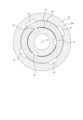
大径シリンダ51bは空気用ポンプ60を構成するものである。空気用ポンプ60は大径シリンダ51bにおいて装着キャップ10に支持されて容器本体2の内部に配置されている。ステム20の下側部分20bの内周面と筒体40の外周面との間には、空気の導入流路61が設けられている。本実施形態では、図3に示すように、4本の導入流路61がステム20の軸線Oを中心とした周方向に等間隔に並べて設けられている。図2に示すように、導入流路61は、筒体40の上端と連接部分20dとの間の円環状の空間を介して空気流路70に連通している。 Thelarge diameter cylinder 51b constitutes anair pump 60. Theair pump 60 is supported by the mountingcap 10 in the large-diameter cylinder 51b and is disposed inside thecontainer body 2. Anair introduction passage 61 is provided between the inner circumferential surface of thelower portion 20b of thestem 20 and the outer circumferential surface of thecylindrical body 40. In this embodiment, as shown in FIG. 3, fourintroduction channels 61 are arranged at equal intervals in the circumferential direction around the axis O of thestem 20. As shown in FIG. 2, theintroduction channel 61 communicates with theair channel 70 via an annular space between the upper end of thecylinder 40 and the connectingportion 20d.

図3に示すように、筒状接続部22の外周面と筒体40の内周面との間には、3本の空気流路70が、軸線Oを中心とした周方向に等間隔に並べて設けられている。本実施形態では、これらの空気流路70は、筒状接続部22の外周面に軸線Oを中心とした周方向に等間隔に並べて設けられた溝で構成されている。それぞれの空気流路70を構成する溝は、何れも断面が略矩形状であり、その断面積ないし断面形状は互いに同一である。なお、空気流路70は、筒体40の内周面に軸線Oを中心とした周方向に等間隔に並べて設けた溝で構成するようにしてもよい。 As shown in FIG. 3, between the outer circumferential surface of thecylindrical connection part 22 and the inner circumferential surface of thecylindrical body 40, threeair flow paths 70 are arranged at equal intervals in the circumferential direction around the axis O. They are arranged side by side. In this embodiment, theseair flow paths 70 are constituted by grooves provided on the outer peripheral surface of the cylindrical connectingportion 22 at equal intervals in a circumferential direction centered on the axis O. The grooves constituting eachair flow path 70 all have a substantially rectangular cross-section, and their cross-sectional area or cross-sectional shape is the same. Note that theair flow path 70 may be constituted by grooves provided on the inner circumferential surface of thecylindrical body 40 at equal intervals in the circumferential direction around the axis O.

図1に示すように、大径シリンダ51bの内部には、大径シリンダ51bの内周面に当接するとともに軸線Oに沿って摺動可能に空気用シール体62が配置されている。円環状の形態を有する空気用シール体62は、ステム20の案内筒部21の下端に係止されており、案内筒部21、フランジ状部分20c及び下側部分20bとともに空気用ポンプ60のピストンを構成している。 As shown in FIG. 1, anair seal 62 is disposed inside the large-diameter cylinder 51b so as to be in contact with the inner circumferential surface of the large-diameter cylinder 51b and to be slidable along the axis O. Theair seal body 62 having an annular shape is locked to the lower end of theguide cylinder part 21 of thestem 20, and is attached to the piston of theair pump 60 together with theguide cylinder part 21, the flange-shapedpart 20c, and thelower part 20b. It consists of

空気用シール体62の内側には筒体40を取り囲む筒状ガイド63が設けられている。筒体40の外周面と筒状ガイド63の内周面との相互間には上下方向に延びるスリット状の隙間が形成されており、当該隙間は大径シリンダ51bの内部の空気を混合室43に向けて流す空気の導入流路64を構成している。筒状ガイド63は、その下端において筒体40に設けられたフランジ44に当接しており、筒体40に対して相対的に僅かに上下方向にスライド可能となっている。筒状ガイド63が筒体40に対して相対的に上方にスライドすると、筒状ガイド63の下端がフランジ44から離間して導入流路64が開かれる。反対に、筒状ガイド63が筒体40に対して相対的に下方にスライドして筒状ガイド63の下端がフランジ44に当接すると導入流路64が閉じられる。 Acylindrical guide 63 surrounding thecylinder 40 is provided inside theair seal 62 . A slit-shaped gap extending in the vertical direction is formed between the outer circumferential surface of thecylinder 40 and the inner circumferential surface of thecylindrical guide 63. It constitutes anintroduction flow path 64 for air flowing toward the air. Thecylindrical guide 63 is in contact with aflange 44 provided on thecylindrical body 40 at its lower end, and is able to slightly slide vertically relative to thecylindrical body 40 . When thecylindrical guide 63 slides upward relative to thecylindrical body 40, the lower end of thecylindrical guide 63 separates from theflange 44, and theintroduction channel 64 is opened. Conversely, when thecylindrical guide 63 slides downward relative to thecylindrical body 40 and the lower end of thecylindrical guide 63 comes into contact with theflange 44, theintroduction channel 64 is closed.

ヘッド部30が押し下げ操作され、ヘッド部30とともにステム20が下方に移動すると、案内筒部21に押されて空気用シール体62が下方に移動して、大径シリンダ51bの内部の空気が加圧されるとともに、筒状ガイド63が筒体40に対して相対的に上方にスライドして導入流路64が開かれる。これにより、大径シリンダ51bの内部の加圧された空気が、導入流路64、4本の導入流路61及び3本の空気流路70を通って混合室43に圧送されて混合室43に流入する。 When thehead section 30 is pressed down and thestem 20 moves downward together with thehead section 30, theair seal body 62 is pushed downward by theguide tube section 21, and the air inside thelarge diameter cylinder 51b is heated. As the pressure is applied, thecylindrical guide 63 slides upward relative to thecylindrical body 40, and theintroduction channel 64 is opened. As a result, the pressurized air inside the large-diameter cylinder 51b is forced into the mixingchamber 43 through theintroduction channel 64, the fourintroduction channels 61, and the threeair channels 70. flows into.

このように、上記構成の液体用ポンプ50及び空気用ポンプ60によれば、ヘッド部30を下方に向けて押下げ操作することで、ステム20により駆動して液体用ポンプ50及び空気用ポンプ60を作動させ、混合室43に液体と空気とを流入させ、これらを混合室43の内部で混合させることができる。 In this way, according to theliquid pump 50 and theair pump 60 configured as described above, by pressing thehead portion 30 downward, theliquid pump 50 and theair pump 60 are driven by thestem 20. can be operated to flow the liquid and air into the mixingchamber 43 and mix them inside the mixingchamber 43.

図2に示すように、混合室43の内部にはボール弁Bが配置されている。ボール弁Bは、隔壁41の上面に設けられた弁座41aと筒状接続部22の下端に設けられた弁押さえ22aとの間に配置されている。ボール弁Bは、弁座41aに接触することで液体流入孔42を閉塞する。また、ボール弁Bは、液体用ポンプ50から混合室43に液体が圧送されると、その圧力により押されて弁座41aから離れ、液体流入孔42を開放する。 As shown in FIG. 2, a ball valve B is arranged inside the mixingchamber 43. The ball valve B is disposed between avalve seat 41a provided on the upper surface of thepartition wall 41 and avalve retainer 22a provided at the lower end of thecylindrical connection portion 22. The ball valve B closes theliquid inflow hole 42 by contacting thevalve seat 41a. Furthermore, when the liquid is pumped from theliquid pump 50 to the mixingchamber 43, the ball valve B is pushed by the pressure and moves away from thevalve seat 41a, opening theliquid inflow hole 42.

本実施形態のフォーマーディスペンサー1は、上記の通り、筒状接続部22の外周面と筒体40の内周面との間に、軸線Oを中心として周方向に等間隔に並べて3本の空気流路70が設けられた構成とされている。 As described above, thefoamer dispenser 1 of this embodiment has three tubes arranged at equal intervals in the circumferential direction centering on the axis O between the outer circumferential surface of thecylindrical connection part 22 and the inner circumferential surface of thecylindrical body 40. It has a configuration in which anair flow path 70 is provided.

また、本実施形態のフォーマーディスペンサー1は、液体用ポンプ50と混合室43との間の液体流路の最小部分である液体流入孔42の断面積が、2.0mm以上、14.5mm以下となる構成とされている。 Further, in thefoamer dispenser 1 of this embodiment, the cross-sectional area of theliquid inflow hole 42, which is the smallest part of the liquid flow path between theliquid pump 50 and the mixingchamber 43, is 2.0 mm2 or more and 14.5 mm. The configuration is such that the number is2 or less.

さらに、本実施形態のフォーマーディスペンサー1では、3本の空気流路70の断面積の合計と液体流路の最小部分である液体流入孔42の断面積との比が、1.0:1.4~1.0:2.8となる構成とされている。すなわち、液体流路の最小部分である液体流入孔42の断面積を、3本の空気流路70の断面積の合計の1.4倍から2.8倍の範囲に設定するようにしている。なお、本実施形態では、3本の空気流路70は、それぞれ一定の断面積で上下方向に延びた構成とされているが、上下方向で断面積が変化する構成とすることもでき、この場合、3本の空気流路70の断面積の合計は、それぞれの空気流路70の最小部分における断面積の合計とする。 Furthermore, in thefoamer dispenser 1 of this embodiment, the ratio of the total cross-sectional area of the threeair channels 70 to the cross-sectional area of theliquid inflow hole 42, which is the smallest part of the liquid channel, is 1.0:1. The configuration is such that the ratio is .4 to 1.0:2.8. That is, the cross-sectional area of theliquid inflow hole 42, which is the smallest part of the liquid flow path, is set to be in the range of 1.4 to 2.8 times the total cross-sectional area of the threeair flow paths 70. . In this embodiment, each of the threeair flow paths 70 has a constant cross-sectional area and extends in the vertical direction, but it is also possible to have a configuration in which the cross-sectional area changes in the vertical direction. In this case, the total cross-sectional area of the threeair flow paths 70 is the sum of the cross-sectional areas of the respectiveair flow paths 70 at their smallest portions.

本実施形態のフォーマーディスペンサー1は、このような構成を有することで、ヘッド部30が高速(例えば70mm/s)で押し下げ操作されても、ノズル31から大きな気泡を含まない均一な泡を吐出することができる。 With such a configuration, thefoamer dispenser 1 of the present embodiment can discharge uniform foam without large bubbles from thenozzle 31 even when thehead portion 30 is pressed down at high speed (for example, 70 mm/s). can do.

ここで、筒状接続部22の外周面と筒体40の内周面との間に設ける空気流路70の本数を2本以下とすると、空気流路70から混合室43への空気の導入バランスが悪く、混合室43の内部において液体と空気とを均一に混合することができず、ノズル31から吐出される泡が部分的に大きな気泡を含んだ不均一なものとなってしまう、という問題が生じることになる。一方、筒状接続部22の外周面と筒体40の内周面との間に設ける空気流路70の本数を4本以上とすると、合計の断面積が同じである場合、それぞれの空気流路70の断面形状における外郭の全周の長さ(周長)の合計が3本の場合に比べて長くなるため、空気流路70を通過する際の空気の抵抗が大きくなって空気の流速が落ち、液の流速に対する空気の遅れにより大きな気泡を生じやすくなる、という問題が生じることになる。 Here, if the number ofair channels 70 provided between the outer circumferential surface of thecylindrical connection part 22 and the inner circumferential surface of thecylindrical body 40 is set to two or less, air is introduced from theair channels 70 into the mixingchamber 43. Due to the poor balance, the liquid and air cannot be mixed uniformly inside the mixingchamber 43, and the foam discharged from thenozzle 31 becomes non-uniform with some large bubbles. Problems will arise. On the other hand, if the number ofair flow paths 70 provided between the outer peripheral surface of thecylindrical connection part 22 and the inner peripheral surface of thecylindrical body 40 is four or more, and the total cross-sectional area is the same, each air flow Since the total circumference length (perimeter) of the outer shell in the cross-sectional shape of thechannel 70 is longer than in the case of three, the resistance of the air when passing through theair channel 70 increases, and the flow rate of the air increases. This causes a problem in that large air bubbles are likely to be generated due to the delay of the air relative to the flow rate of the liquid.

また、液体用ポンプ50と混合室43との間の液体流路の最小部分である液体流入孔42の断面積を2.0mm未満とすると、ヘッド部30の押し下げ操作をする際に必要な押下げ荷重が大きくなって、その操作がさらにし難くなる、という問題が生じることになる。一方、液体用ポンプ50と混合室43との間の液体流路の最小部分である液体流入孔42の断面積を14.5mmより大きくすると、小径シリンダ51aの外径を大きくする必要が生じるため、フォーマーディスペンサー1が大型化し、フォーマーディスペンサー1が装着される容器本体2の設計の制約が厳しくなるなどの問題が生じることになる。 Furthermore, if the cross-sectional area of theliquid inlet hole 42, which is the smallest part of the liquid flow path between theliquid pump 50 and the mixingchamber 43, is less than 2.0 mm2, the cross-sectional area of the liquid inlet hole42 , which is the smallest part of the liquid flow path between theliquid pump 50 and the mixingchamber 43, is less than 2.0 mm2. A problem arises in that the push-down load increases, making the operation even more difficult. On the other hand, if the cross-sectional area of theliquid inlet hole 42, which is the smallest part of the liquid flow path between theliquid pump 50 and the mixingchamber 43, is made larger than 14.5mm2 , it becomes necessary to increase the outer diameter of thesmall diameter cylinder 51a. Therefore, problems arise such as theformer dispenser 1 becomes larger and the design of thecontainer body 2 to which theformer dispenser 1 is attached becomes more severely restricted.

これに対し、本実施形態のフォーマーディスペンサー1はで、上記の通り、筒状接続部22の外周面と筒体40の内周面との間に、軸線Oを中心として周方向に等間隔に並べて3本の空気流路70を設け、液体流路の最小部分である液体流入孔42の断面積を2.0mm以上、14.5mm以下とし、3本の空気流路70の断面積の合計と液体流路の最小部分である液体流入孔42の断面積との比を1.0:1.4~1.0:2.8とするようにしたので、フォーマーディスペンサー1を小型化し、ヘッド部30の押下げ操作を容易に行い得るようにしつつノズル31から均一な泡を吐出させることができる。 On the other hand, in theformer dispenser 1 of the present embodiment, as described above, the outer circumferential surface of thecylindrical connection part 22 and the inner circumferential surface of thecylindrical body 40 are arranged at equal intervals in the circumferential direction centering on the axis O.Three air channels 70 are arranged in parallel, and the cross-sectional area of theliquid inflow hole 42, which is the smallest part of the liquid channel, is set to 2.0 mm2 or more and 14.5 mm2 or less, and the cross-sectional area of the threeair channels 70 is Since the ratio between the total area and the cross-sectional area of theliquid inflow hole 42, which is the smallest part of the liquid flow path, is set to 1.0:1.4 to 1.0:2.8, thefoamer dispenser 1 It is possible to reduce the size of thehead part 30, and to easily perform the depressing operation of thehead part 30, while uniformly discharging bubbles from thenozzle 31.

本発明は前記実施の形態に限定されるものではなく、その要旨を逸脱しない範囲で種々変更可能であることはいうまでもない。 It goes without saying that the present invention is not limited to the embodiments described above, and can be modified in various ways without departing from the spirit thereof.

例えば、前記実施形態では、それぞれの空気流路70の断面形状を略矩形としているが、その形状は種々変更可能である。 For example, in the embodiment described above, eachair flow path 70 has a substantially rectangular cross-sectional shape, but the shape can be changed in various ways.

1 フォーマーディスペンサー
2 容器本体
2a 口部
2b 雄ねじ
10 装着キャップ
10a 天壁
10b 装着筒壁
10c 雌ねじ
10d 支持筒部
20 ステム
20a 上側部分
20b 下側部分
20c フランジ状部分
20d 連接部分
21 案内筒部
22 筒状接続部
22a 弁押さえ
23 流出孔
30 ヘッド部
31 ノズル
32 吐出口
40 筒体
41 隔壁
41a 弁座
42 液体流入孔
43 混合室
44 フランジ
50 液体用ポンプ
51 シリンダ部材
51a 小径シリンダ
51b 大径シリンダ
52 液体用シール体
53 バネ部材
54 ポペット
54a 弁部
60 空気用ポンプ
61 導入流路
62 空気用シール体
63 筒状ガイド
64 導入流路
70 空気流路
80 発泡部材
O 軸線
B ボール弁
1Former dispenser 2 Containermain body2a Mouth part2b Male thread 10Mounting cap10a Top wall 10b Mountingcylinder wall10c Female thread 10dSupport cylinder part 20Stem 20aUpper part 20bLower part 20c Flange-like part20d Connecting part 21Guide cylinder part 22Cylinder Connecting part22a Valve holder 23Outflow hole 30Head part 31Nozzle 32Discharge port 40Cylindrical body 41Partition wall41a Valve seat 42Liquid inflow hole 43Mixing chamber 44Flange 50Liquid pump 51Cylinder member 51aSmall diameter cylinder 51bLarge diameter cylinder 52Liquid Seal body 53Spring member 54Poppet54a Valve part 60Air pump 61Introduction channel 62Air seal body 63Cylindrical guide 64Introduction channel 70Air channel 80 Foaming member O Axis line B Ball valve

Claims (3)

Translated fromJapanese
容器本体の口部に装着された装着キャップと、
流出孔を備えた筒状接続部を有し、前記装着キャップから突出するステムと、
ノズルを備え、前記ステムの上端に取り付けられたヘッド部と、
液体流入孔を備えた隔壁を有し、前記筒状接続部に外側から嵌合して前記筒状接続部と前記隔壁との間に混合室を区画形成する筒体と、
前記装着キャップに支持され、前記ヘッド部の押し下げ操作により前記ステムに駆動されて前記容器本体の内部の液体を前記液体流入孔から前記混合室の内部に向けて圧送する液体用ポンプと、
前記装着キャップに支持され、前記ヘッド部の押し下げ操作により前記ステムに駆動されて外部から取り込んだ空気を前記筒状接続部の外周面と前記筒体の内周面との間に設けられた空気流路から前記混合室に向けて圧送する空気用ポンプと、
前記ステム及び前記ノズルの少なくとも何れか一方に配置され、前記混合室で空気と混合された液体を発泡させる発泡部材と、を有し、
前記筒状接続部の外周面と前記筒体の内周面との間に、周方向に等間隔に並べて3本の前記空気流路が設けられ、
前記液体用ポンプと前記混合室との間の液体流路の最小部分の断面積が、2.0mm以上、14.5mm以下であり、
3本の前記空気流路の断面積の合計と前記液体流路の最小部分の断面積との比が、1.0:1.4~1.0:2.8である、ことを特徴とするフォーマーディスペンサー。
an attachment cap attached to the mouth of the container body;
a stem protruding from the mounting cap and having a cylindrical connection portion with an outflow hole;
a head portion including a nozzle and attached to the upper end of the stem;
a cylindrical body having a partition wall with a liquid inflow hole and fitting into the cylindrical connection part from the outside to define a mixing chamber between the cylindrical connection part and the partition wall;
a liquid pump that is supported by the mounting cap and is driven by the stem when the head portion is pushed down to pump the liquid inside the container body from the liquid inflow hole toward the inside of the mixing chamber;
An air provided between the outer circumferential surface of the cylindrical connection part and the inner circumferential surface of the cylindrical body, which is supported by the mounting cap and is driven by the stem when the head section is pushed down and is taken in from the outside. an air pump that pumps air from the flow path toward the mixing chamber;
a foaming member disposed on at least one of the stem and the nozzle and foaming the liquid mixed with air in the mixing chamber;
The three air flow paths are arranged at equal intervals in the circumferential direction between the outer peripheral surface of the cylindrical connection part and the inner peripheral surface of the cylindrical body,
The cross-sectional area of the smallest portion of the liquid flow path between the liquid pump and the mixing chamber is 2.0 mm2 or more and 14.5 mm2 or less,
The ratio of the total cross-sectional area of the three air flow paths to the cross-sectional area of the smallest portion of the liquid flow path is 1.0:1.4 to 1.0:2.8. foamer dispenser.
3本の前記空気流路が、前記筒状接続部の外周面に周方向に等間隔に並べて設けられた溝で構成されている、請求項1に記載のフォーマーディスペンサー。 The former dispenser according to claim 1, wherein the three air flow paths are constituted by grooves arranged at equal intervals in the circumferential direction on the outer peripheral surface of the cylindrical connecting portion. 前記液体流路の最小部分が前記液体流入孔である、請求項1または2に記載のフォーマーディスペンサー。 The former dispenser according to claim 1 or 2, wherein the smallest part of the liquid flow path is the liquid inlet hole.
JP2022121008A2022-07-282022-07-28 foamer dispenserPendingJP2024017991A (en)

Priority Applications (1)

Application NumberPriority DateFiling DateTitle
JP2022121008AJP2024017991A (en)2022-07-282022-07-28 foamer dispenser

Applications Claiming Priority (1)

Application NumberPriority DateFiling DateTitle
JP2022121008AJP2024017991A (en)2022-07-282022-07-28 foamer dispenser

Publications (1)

Publication NumberPublication Date
JP2024017991Atrue JP2024017991A (en)2024-02-08

Family

ID=89806779

Family Applications (1)

Application NumberTitlePriority DateFiling Date
JP2022121008APendingJP2024017991A (en)2022-07-282022-07-28 foamer dispenser

Country Status (1)

CountryLink
JP (1)JP2024017991A (en)

Similar Documents

PublicationPublication DateTitle
US9868128B2 (en)Foam dispensing assembly
US20050115988A1 (en)Multiple liquid foamer
CN107187723B (en) Three-piece pump
JP6301528B2 (en) Foam forming assembly and squeeze former
JP2006524766A (en) Foaming liquid dispenser
JP2002542124A (en) Two-phase dispenser device
JP7493201B2 (en) Pump dispenser
TW201801798A (en)Foam discharge container
KR100858366B1 (en) Foam Blow Pumps
JP2018083637A (en)Foam discharge container
JP6793058B2 (en) Foam ejection container
TWI786299B (en) Foam dispenser and foam spray container
JP6389770B2 (en) Nozzle member
JP2024017991A (en) foamer dispenser
JP2014046938A (en)Bubble jet container
JP6893745B2 (en) Former dispenser
WO2023082041A1 (en)Bottom-mounted large-capacity single-air pump foam generating device
JP6945408B2 (en) Former pump
KR102840308B1 (en)Trigger-type dispensing device equipped with replaceable spray nozzles
JP7283986B2 (en) foam dispenser
JP2020104930A (en)Foam dispenser
WO2023153503A1 (en)Pump dispenser
JP7076304B2 (en) Foam ejector
JP2018016404A (en)Foamer dispenser
JP2024122452A (en) Foam dispenser

Legal Events

DateCodeTitleDescription
A621Written request for application examination

Free format text:JAPANESE INTERMEDIATE CODE: A621

Effective date:20250206


[8]ページ先頭

©2009-2025 Movatter.jp