JP2024001343A - System and method for docking medical device - Google Patents
System and method for docking medical deviceDownload PDFInfo
- Publication number
- JP2024001343A JP2024001343AJP2023188487AJP2023188487AJP2024001343AJP 2024001343 AJP2024001343 AJP 2024001343AJP 2023188487 AJP2023188487 AJP 2023188487AJP 2023188487 AJP2023188487 AJP 2023188487AJP 2024001343 AJP2024001343 AJP 2024001343A
- Authority
- JP
- Japan
- Prior art keywords
- drive
- instrument
- drive output
- torque
- output
- Prior art date
- Legal status (The legal status is an assumption and is not a legal conclusion. Google has not performed a legal analysis and makes no representation as to the accuracy of the status listed.)
- Pending
Links
- 238000000034methodMethods0.000titleclaimsabstractdescription158
- 238000003032molecular dockingMethods0.000titleclaimsabstractdescription40
- 230000004044responseEffects0.000claimsabstractdescription35
- 230000007246mechanismEffects0.000claimsdescription171
- 230000033001locomotionEffects0.000claimsdescription26
- 238000004891communicationMethods0.000claimsdescription15
- 230000003213activating effectEffects0.000claimsdescription13
- 238000010586diagramMethods0.000abstractdescription9
- 230000008569processEffects0.000description21
- 210000002435tendonAnatomy0.000description16
- 238000003780insertionMethods0.000description15
- 230000037431insertionEffects0.000description15
- 238000013519translationMethods0.000description14
- 230000014616translationEffects0.000description14
- 210000003484anatomyAnatomy0.000description11
- 238000013276bronchoscopyMethods0.000description10
- 239000012636effectorSubstances0.000description9
- 230000004438eyesightEffects0.000description8
- 230000003287optical effectEffects0.000description8
- 238000003860storageMethods0.000description8
- 210000001015abdomenAnatomy0.000description7
- 230000006870functionEffects0.000description7
- 238000003384imaging methodMethods0.000description6
- 230000004807localizationEffects0.000description6
- 230000010355oscillationEffects0.000description6
- 230000001225therapeutic effectEffects0.000description6
- 210000003708urethraAnatomy0.000description6
- 210000001503jointAnatomy0.000description5
- 210000002414legAnatomy0.000description5
- 238000012545processingMethods0.000description5
- 210000000707wristAnatomy0.000description5
- 230000002457bidirectional effectEffects0.000description4
- 238000013461designMethods0.000description4
- 238000001839endoscopyMethods0.000description4
- 230000002262irrigationEffects0.000description4
- 238000003973irrigationMethods0.000description4
- 238000013507mappingMethods0.000description4
- 230000005855radiationEffects0.000description4
- 230000001954sterilising effectEffects0.000description4
- 238000004659sterilization and disinfectionMethods0.000description4
- 238000001356surgical procedureMethods0.000description4
- 230000002792vascularEffects0.000description4
- 230000000007visual effectEffects0.000description4
- 210000000683abdominal cavityAnatomy0.000description3
- 230000003187abdominal effectEffects0.000description3
- 238000005452bendingMethods0.000description3
- 230000008901benefitEffects0.000description3
- 230000008859changeEffects0.000description3
- 230000006835compressionEffects0.000description3
- 238000007906compressionMethods0.000description3
- 238000002591computed tomographyMethods0.000description3
- 238000004590computer programMethods0.000description3
- 230000008878couplingEffects0.000description3
- 238000010168coupling processMethods0.000description3
- 238000005859coupling reactionMethods0.000description3
- 238000006073displacement reactionMethods0.000description3
- 210000001105femoral arteryAnatomy0.000description3
- 239000012530fluidSubstances0.000description3
- 230000002496gastric effectEffects0.000description3
- 210000000626ureterAnatomy0.000description3
- 238000001574biopsyMethods0.000description2
- 238000004364calculation methodMethods0.000description2
- 230000007423decreaseEffects0.000description2
- 238000001514detection methodMethods0.000description2
- 230000001747exhibiting effectEffects0.000description2
- 210000004013groinAnatomy0.000description2
- 210000003734kidneyAnatomy0.000description2
- 238000002357laparoscopic surgeryMethods0.000description2
- 210000004072lungAnatomy0.000description2
- 238000005259measurementMethods0.000description2
- 239000013307optical fiberSubstances0.000description2
- 230000005693optoelectronicsEffects0.000description2
- 230000002685pulmonary effectEffects0.000description2
- 230000035945sensitivityEffects0.000description2
- 238000012546transferMethods0.000description2
- 230000001960triggered effectEffects0.000description2
- 206010073306Exposure to radiationDiseases0.000description1
- 208000000913Kidney CalculiDiseases0.000description1
- 206010029148NephrolithiasisDiseases0.000description1
- 241001464870[Ruminococcus] torquesSpecies0.000description1
- 238000012084abdominal surgeryMethods0.000description1
- 210000003815abdominal wallAnatomy0.000description1
- 230000004308accommodationEffects0.000description1
- 230000009471actionEffects0.000description1
- 230000004913activationEffects0.000description1
- 239000000853adhesiveSubstances0.000description1
- 230000001070adhesive effectEffects0.000description1
- 238000004458analytical methodMethods0.000description1
- 238000013459approachMethods0.000description1
- 210000001367arteryAnatomy0.000description1
- 230000000712assemblyEffects0.000description1
- 238000000429assemblyMethods0.000description1
- 210000002302brachial arteryAnatomy0.000description1
- 210000001715carotid arteryAnatomy0.000description1
- 230000009849deactivationEffects0.000description1
- 230000003247decreasing effectEffects0.000description1
- 238000003745diagnosisMethods0.000description1
- 230000009977dual effectEffects0.000description1
- 210000002310elbow jointAnatomy0.000description1
- 239000000835fiberSubstances0.000description1
- 238000002594fluoroscopyMethods0.000description1
- 239000012634fragmentSubstances0.000description1
- 238000002575gastroscopyMethods0.000description1
- 230000005484gravityEffects0.000description1
- 230000036541healthEffects0.000description1
- 210000001624hipAnatomy0.000description1
- 238000010348incorporationMethods0.000description1
- 238000007373indentationMethods0.000description1
- 230000036512infertilityEffects0.000description1
- 230000003993interactionEffects0.000description1
- 230000003902lesionEffects0.000description1
- 230000003211malignant effectEffects0.000description1
- 239000000463materialSubstances0.000description1
- 230000013011matingEffects0.000description1
- 239000012528membraneSubstances0.000description1
- 238000012986modificationMethods0.000description1
- 230000004048modificationEffects0.000description1
- 238000012544monitoring processMethods0.000description1
- 230000007170pathologyEffects0.000description1
- 238000011471prostatectomyMethods0.000description1
- 230000001012protectorEffects0.000description1
- 230000029058respiratory gaseous exchangeEffects0.000description1
- 238000005096rolling processMethods0.000description1
- 230000011218segmentationEffects0.000description1
- 238000000926separation methodMethods0.000description1
- 238000001228spectrumMethods0.000description1
- 230000000087stabilizing effectEffects0.000description1
- 230000003068static effectEffects0.000description1
- 239000004575stoneSubstances0.000description1
- 238000010415tidyingMethods0.000description1
- 238000003325tomographyMethods0.000description1
- 210000003437tracheaAnatomy0.000description1
- 230000009466transformationEffects0.000description1
- 238000009211ultrasonic lithotripsyMethods0.000description1
- 210000000689upper legAnatomy0.000description1
- 210000001835visceraAnatomy0.000description1
Images


Classifications
- A—HUMAN NECESSITIES
- A61—MEDICAL OR VETERINARY SCIENCE; HYGIENE
- A61B—DIAGNOSIS; SURGERY; IDENTIFICATION
- A61B34/00—Computer-aided surgery; Manipulators or robots specially adapted for use in surgery
- A61B34/70—Manipulators specially adapted for use in surgery
- A61B34/71—Manipulators operated by drive cable mechanisms
- A—HUMAN NECESSITIES
- A61—MEDICAL OR VETERINARY SCIENCE; HYGIENE
- A61B—DIAGNOSIS; SURGERY; IDENTIFICATION
- A61B34/00—Computer-aided surgery; Manipulators or robots specially adapted for use in surgery
- A61B34/30—Surgical robots
- A—HUMAN NECESSITIES
- A61—MEDICAL OR VETERINARY SCIENCE; HYGIENE
- A61B—DIAGNOSIS; SURGERY; IDENTIFICATION
- A61B17/00—Surgical instruments, devices or methods
- A61B17/00234—Surgical instruments, devices or methods for minimally invasive surgery
- A—HUMAN NECESSITIES
- A61—MEDICAL OR VETERINARY SCIENCE; HYGIENE
- A61B—DIAGNOSIS; SURGERY; IDENTIFICATION
- A61B34/00—Computer-aided surgery; Manipulators or robots specially adapted for use in surgery
- A61B34/20—Surgical navigation systems; Devices for tracking or guiding surgical instruments, e.g. for frameless stereotaxis
- A—HUMAN NECESSITIES
- A61—MEDICAL OR VETERINARY SCIENCE; HYGIENE
- A61B—DIAGNOSIS; SURGERY; IDENTIFICATION
- A61B17/00—Surgical instruments, devices or methods
- A61B17/00234—Surgical instruments, devices or methods for minimally invasive surgery
- A61B2017/00292—Surgical instruments, devices or methods for minimally invasive surgery mounted on or guided by flexible, e.g. catheter-like, means
- A61B2017/003—Steerable
- A61B2017/00318—Steering mechanisms
- A61B2017/00323—Cables or rods
- A—HUMAN NECESSITIES
- A61—MEDICAL OR VETERINARY SCIENCE; HYGIENE
- A61B—DIAGNOSIS; SURGERY; IDENTIFICATION
- A61B17/00—Surgical instruments, devices or methods
- A61B2017/00477—Coupling
- A—HUMAN NECESSITIES
- A61—MEDICAL OR VETERINARY SCIENCE; HYGIENE
- A61B—DIAGNOSIS; SURGERY; IDENTIFICATION
- A61B34/00—Computer-aided surgery; Manipulators or robots specially adapted for use in surgery
- A61B34/20—Surgical navigation systems; Devices for tracking or guiding surgical instruments, e.g. for frameless stereotaxis
- A61B2034/2046—Tracking techniques
- A61B2034/2051—Electromagnetic tracking systems
- A—HUMAN NECESSITIES
- A61—MEDICAL OR VETERINARY SCIENCE; HYGIENE
- A61B—DIAGNOSIS; SURGERY; IDENTIFICATION
- A61B34/00—Computer-aided surgery; Manipulators or robots specially adapted for use in surgery
- A61B34/20—Surgical navigation systems; Devices for tracking or guiding surgical instruments, e.g. for frameless stereotaxis
- A61B2034/2074—Interface software
- A—HUMAN NECESSITIES
- A61—MEDICAL OR VETERINARY SCIENCE; HYGIENE
- A61B—DIAGNOSIS; SURGERY; IDENTIFICATION
- A61B34/00—Computer-aided surgery; Manipulators or robots specially adapted for use in surgery
- A61B34/30—Surgical robots
- A61B2034/301—Surgical robots for introducing or steering flexible instruments inserted into the body, e.g. catheters or endoscopes
- A—HUMAN NECESSITIES
- A61—MEDICAL OR VETERINARY SCIENCE; HYGIENE
- A61B—DIAGNOSIS; SURGERY; IDENTIFICATION
- A61B34/00—Computer-aided surgery; Manipulators or robots specially adapted for use in surgery
- A61B34/30—Surgical robots
- A61B2034/302—Surgical robots specifically adapted for manipulations within body cavities, e.g. within abdominal or thoracic cavities
- A—HUMAN NECESSITIES
- A61—MEDICAL OR VETERINARY SCIENCE; HYGIENE
- A61B—DIAGNOSIS; SURGERY; IDENTIFICATION
- A61B34/00—Computer-aided surgery; Manipulators or robots specially adapted for use in surgery
- A61B34/30—Surgical robots
- A61B2034/303—Surgical robots specifically adapted for manipulations within body lumens, e.g. within lumen of gut, spine, or blood vessels
- A—HUMAN NECESSITIES
- A61—MEDICAL OR VETERINARY SCIENCE; HYGIENE
- A61B—DIAGNOSIS; SURGERY; IDENTIFICATION
- A61B90/00—Instruments, implements or accessories specially adapted for surgery or diagnosis and not covered by any of the groups A61B1/00 - A61B50/00, e.g. for luxation treatment or for protecting wound edges
- A61B90/06—Measuring instruments not otherwise provided for
- A61B2090/064—Measuring instruments not otherwise provided for for measuring force, pressure or mechanical tension
- A61B2090/066—Measuring instruments not otherwise provided for for measuring force, pressure or mechanical tension for measuring torque
- A—HUMAN NECESSITIES
- A61—MEDICAL OR VETERINARY SCIENCE; HYGIENE
- A61B—DIAGNOSIS; SURGERY; IDENTIFICATION
- A61B2562/00—Details of sensors; Constructional details of sensor housings or probes; Accessories for sensors
- A61B2562/02—Details of sensors specially adapted for in-vivo measurements
- A61B2562/0261—Strain gauges
- A—HUMAN NECESSITIES
- A61—MEDICAL OR VETERINARY SCIENCE; HYGIENE
- A61B—DIAGNOSIS; SURGERY; IDENTIFICATION
- A61B2562/00—Details of sensors; Constructional details of sensor housings or probes; Accessories for sensors
- A61B2562/08—Sensors provided with means for identification, e.g. barcodes or memory chips
- A—HUMAN NECESSITIES
- A61—MEDICAL OR VETERINARY SCIENCE; HYGIENE
- A61B—DIAGNOSIS; SURGERY; IDENTIFICATION
- A61B90/00—Instruments, implements or accessories specially adapted for surgery or diagnosis and not covered by any of the groups A61B1/00 - A61B50/00, e.g. for luxation treatment or for protecting wound edges
- A61B90/90—Identification means for patients or instruments, e.g. tags
- A61B90/98—Identification means for patients or instruments, e.g. tags using electromagnetic means, e.g. transponders
Landscapes
- Health & Medical Sciences (AREA)
- Surgery (AREA)
- Life Sciences & Earth Sciences (AREA)
- Engineering & Computer Science (AREA)
- Medical Informatics (AREA)
- General Health & Medical Sciences (AREA)
- Biomedical Technology (AREA)
- Heart & Thoracic Surgery (AREA)
- Nuclear Medicine, Radiotherapy & Molecular Imaging (AREA)
- Molecular Biology (AREA)
- Animal Behavior & Ethology (AREA)
- Veterinary Medicine (AREA)
- Public Health (AREA)
- Robotics (AREA)
- Physics & Mathematics (AREA)
- Electromagnetism (AREA)
- Oral & Maxillofacial Surgery (AREA)
- Pathology (AREA)
- Manipulator (AREA)
Abstract
Translated fromJapaneseDescription
Translated fromJapanese (優先出願)
本出願は、2018年9月28日出願の米国特許仮出願第62/738,483号の優先権を主張し、参照によりその開示の全体が本書に組み込まれる。(Priority application)
This application claims priority to U.S. Provisional Application No. 62/738,483, filed September 28, 2018, the entire disclosure of which is incorporated herein by reference.
(発明の分野)
本明細書に開示されるシステム及び方法は、医療器具をドッキングすることを目的とし、より具体的には、予め張力をかけられたプルワイヤを含むことができるロボット医療器具を対応する器具駆動機構にドッキングするためのシステム及び方法に関する。(Field of invention)
The systems and methods disclosed herein are for docking medical instruments, and more specifically, for docking a robotic medical instrument, which may include a pre-tensioned pull wire, into a corresponding instrument drive mechanism. SYSTEMS AND METHODS FOR DOCKING.
ロボット制御可能な医療システムは、内視鏡法、腹腔鏡法、及びその他を含む、多種多様な医療処置において使用することができる。これらの処置のいくつかでは、ロボット制御式医療器具をロボットアームなどの器具位置付け装置にドッキングさせることができる。一旦ドッキングされると、器具位置付け装置は、医療器具を操作して処置を行うことができる。 Robotically controllable medical systems can be used in a wide variety of medical procedures, including endoscopic procedures, laparoscopic procedures, and others. For some of these procedures, a robotically controlled medical instrument may be docked to an instrument positioning device, such as a robotic arm. Once docked, the instrument positioning device can manipulate medical instruments to perform procedures.
本開示のシステム、方法及び装置はそれぞれ、いくつかの革新的な態様を有し、そのうちの1つも、本明細書に開示される望ましい属性を単独で司るものではない。 The systems, methods, and apparatus of the present disclosure each have several innovative aspects, no single one of which is solely responsible for the desirable attributes disclosed herein.
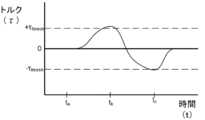
第1の態様では、ロボット医療システムは、ロボット医療器具のハンドル上の対応する駆動入力を回転させこれに係合するように構成された駆動出力であって、ロボット医療器具が、駆動入力によって作動される予め張力をかけられたプルワイヤを含む、駆動出力と、駆動出力と関連付けられ、駆動出力を回転させるように構成されたモータと、駆動出力に関連付けられ、駆動出力に付与されたトルクを測定するように構成されたトルクセンサと、を含む、器具駆動機構と、少なくとも1つのプロセッサと通信する少なくとも1つのコンピュータ可読メモリであって、少なくとも1つのプロセッサに、駆動出力に関連付けられたモータを起動させて、駆動出力に関連付けられたトルクセンサからのトルク信号に応答して駆動出力を回転させる、そこに記憶されたコンピュータ実行可能命令を有する、コンピュータ可読メモリと、を含む。 In a first aspect, a robotic medical system includes a drive output configured to rotate and engage a corresponding drive input on a handle of a robotic medical instrument, the robotic medical instrument being actuated by the drive input. a drive output including a pre-tensioned pull wire that is connected to the drive output; a motor associated with the drive output and configured to rotate the drive output; and a motor associated with the drive output that measures torque imparted to the drive output; a torque sensor configured to activate a motor associated with a drive output; and at least one computer readable memory in communication with the at least one processor. a computer-readable memory having computer-executable instructions stored therein for rotating the drive output in response to a torque signal from a torque sensor associated with the drive output.
いくつかの実施形態では、ロボット医療システムは、次の機能の1つ以上を任意の組み合わせで含めることができ、(a)命令が駆動出力を回転させて、駆動出力を対応する駆動出力と整合させ、(b)命令が、トルク信号が閾値を超えたことに応答して、プロセッサにモータを起動させ、(c)命令が、閾値を下回るトルク信号に応答して、プロセッサにモータを停止させ、(d)トルク信号が、駆動出力上に付与されたトルクの方向を示し、命令が、プロセッサに、モータを起動させて、付与されたトルクの方向と同じ方向にモータを回転させ、(e)モータの回転速度が、トルク信号に基づいて決定された測定トルクに比例し、(f)モータの回転速度が一定であり、(g)駆動出力がギヤであり、駆動入力がソケットであり、(h)駆動出力がソケットであり、駆動入力がギヤであり、(i)命令は、プロセッサに、システムが負荷器具状態にあるとき、駆動出力に関連付けられたモータを起動させて、トルク信号に応答して駆動出力を回転させ、(j)トルクセンサはひずみゲージを含み、(k)ひずみゲージが、器具駆動機構のハウジングとモータとの間に位置付けられ、及び/又は(l)トルクセンサが双方向である。 In some embodiments, a robotic medical system can include one or more of the following features in any combination, including: (a) instructions for rotating a drive output to align the drive output with a corresponding drive output; (b) the instructions cause the processor to start the motor in response to the torque signal exceeding the threshold; and (c) the instructions cause the processor to stop the motor in response to the torque signal below the threshold. , (d) the torque signal indicates the direction of the applied torque on the drive output, and the instructions cause the processor to start the motor to rotate the motor in the same direction as the applied torque; (f) the rotational speed of the motor is constant; (g) the drive output is a gear and the drive input is a socket; (h) the drive output is a socket and the drive input is a gear; (i) the instructions cause the processor to start the motor associated with the drive output and respond to the torque signal when the system is in a load appliance state; responsively rotating the drive output; (j) the torque sensor includes a strain gauge; (k) the strain gauge is positioned between the instrument drive mechanism housing and the motor; and/or (l) the torque sensor includes a strain gauge; It goes both ways.
別の態様では、コンピュータ可読媒体は、少なくとも1つのプロセッサに、器具駆動機構の駆動出力に関連付けられたトルクセンサからトルク信号を受信させ、トルクセンサからのトルク信号が閾値を超えることに応答して、駆動出力を回転させるために、駆動出力に関連付けられたモータを起動させ、モータを停止させて、トルクセンサからのトルク信号が閾値を下回ったことに応答して、モータを停止させるように構成された命令を含むことができる。 In another aspect, the computer-readable medium causes the at least one processor to receive a torque signal from a torque sensor associated with a drive output of the instrument drive mechanism, and in response to the torque signal from the torque sensor exceeding a threshold. , configured to start a motor associated with the drive output to rotate the drive output, stop the motor, and stop the motor in response to the torque signal from the torque sensor falling below a threshold. can contain instructions that have been executed.
いくつかの実施形態では、コンピュータ可読媒体は、以下の特徴のうちの1つ以上を任意の組み合わせで更に含んでもよく、(a)命令が、少なくとも1つのプロセッサに、駆動出力を回転させて、駆動出力を駆動入力又はロボット医療器具と整合させるように構成され、ロボット医療器具が、駆動入力に関連付けられた少なくとも1つの予め張力をかけられたプルワイヤを含み、(b)トルク信号が、駆動出力上に付与されたトルクの方向を示し、命令が、少なくとも1つのプロセッサに、モータを起動させて、付与されたトルクの方向と同じ方向にモータを回転させ、(c)命令は、モータに、トルク信号に基づいて決定された測定トルクに比例する回転速度で駆動出力を回転させるように構成され、(d)命令は、モータに、一定の回転速度で駆動出力を回転させるように構成されており、及び/又は(e)命令は、システムが負荷器具状態にあるときに、トルク信号に応答して、少なくとも1つのプロセッサに駆動出力に関連付けられたモータを起動させて、駆動出力を回転させる。 In some embodiments, the computer-readable medium may further include one or more of the following features in any combination, wherein (a) instructions cause the at least one processor to rotate a drive output; (b) the torque signal is configured to align the drive output with the drive input or the robotic medical device, the robotic medical device including at least one pre-tensioned pull wire associated with the drive input; (c) the instructions cause the at least one processor to activate the motor to rotate the motor in the same direction as the direction of the applied torque; (d) the instructions are configured to cause the motor to rotate the drive output at a constant rotational speed; and (d) the instructions are configured to cause the motor to rotate the drive output at a constant rotational speed. and/or (e) the instructions, in response to the torque signal, cause the at least one processor to activate a motor associated with the drive output to rotate the drive output when the system is in a load equipment state. .
別の態様では、ロボット医療器具の駆動入力と器具駆動機構の駆動出力とを整合させるための方法は、器具駆動機構の駆動出力に関連付けられたトルクセンサからトルク信号を受信することを含み、トルク信号は、駆動出力に付与されたトルクを示し、トルク信号を閾値と比較することと、駆動出力に関連付けられた器具駆動機構のモータを起動させて、閾値を超えるトルク信号に応答して駆動出力を回転させることと、モータを停止させて、トルクセンサからのトルク信号が閾値を下回ったことに応答して、モータを停止させることと、を含む。 In another aspect, a method for aligning a drive input of a robotic medical instrument with a drive output of an instrument drive mechanism includes receiving a torque signal from a torque sensor associated with a drive output of the instrument drive mechanism; The signal is indicative of torque imparted to the drive output, and includes comparing the torque signal to a threshold value and activating a motor of an instrument drive mechanism associated with the drive output to reduce the drive output in response to the torque signal exceeding the threshold value. and stopping the motor in response to the torque signal from the torque sensor falling below a threshold.
いくつかの実施形態では、方法は、任意の組み合わせにおける以下の特徴のうちの1つ以上を含むことができ(a)駆動出力が、駆動出力をロボット医療器具の駆動入力と整合させるために回転され、(b)ロボット医療器具が、駆動入力に関連付けられた少なくとも1つの予め張力をかけられたプルワイヤを含み、(c)トルク信号が、駆動出力上に付与されたトルクの方向を示し、方法が、モータを起動させて、付与されたトルクの方向と同じ方向にモータを回転させることを含み、(d)モータの回転速度が、トルク信号に基づいて決定された測定トルクに比例し、(e)モータの回転速度が一定であり、(f)駆動出力がギヤであり、駆動入力がソケットであり、(g)駆動出力がソケットであり、駆動入力がギヤである、及び/又は(h)起動工程及び停止工程が、負荷器具状態にあるときに発生する。 In some embodiments, the method can include one or more of the following features in any combination: (a) the drive output rotates to align the drive output with the drive input of the robotic medical instrument; (b) the robotic medical device includes at least one pre-tensioned pull wire associated with the drive input; (c) the torque signal indicates a direction of the torque imparted on the drive output; (d) the rotational speed of the motor is proportional to the measured torque determined based on the torque signal; e) the rotational speed of the motor is constant, (f) the drive output is a gear and the drive input is a socket, (g) the drive output is a socket and the drive input is a gear, and/or (h ) The startup and shutdown steps occur when the device is in a loaded appliance state.
別の態様では、ロボット医療システムは、ロボット医療器具のハンドル上の駆動入力を回転させこれに係合するように構成された駆動出力であって、ロボット医療器具は、駆動入力に関連付けられたプルワイヤを含む、駆動出力と、駆動出力に関連付けられ、駆動出力を回転させるように構成されたモータと、駆動出力に関連付けられ、駆動出力に付与されたトルクを測定するように構成されたトルクセンサと、を備える、器具駆動機構と、少なくとも1つのプロセッサと通信する少なくとも1つのコンピュータ可読メモリであって、メモリは、少なくとも1つのコンピュータ可読メモリに記憶されたコンピュータ実行可能命令を有し、少なくとも1つのプロセッサに、駆動出力に関連付けられたモータを起動させて、駆動出力に関連付けられたトルクセンサによって測定されたトルク信号が閾値を超える第1の回転位置まで、駆動出力を第1の方向に回転させ、トルクセンサによって測定されたトルク信号が閾値を超える、第2の回転位置が閾値を超えるまで、モータに駆動出力を第2の方向に回転させ、第1の回転位置と第2の回転位置との間の回転距離を決定させる、メモリと、を備える。 In another aspect, a robotic medical system includes a drive output configured to rotate and engage a drive input on a handle of a robotic medical instrument, the robotic medical instrument having a pull wire associated with the drive input. a drive output, a motor associated with the drive output and configured to rotate the drive output, and a torque sensor associated with the drive output and configured to measure torque applied to the drive output. at least one computer-readable memory in communication with the at least one processor, the memory having computer-executable instructions stored in the at least one computer-readable memory, the at least one causing the processor to activate a motor associated with the drive output to rotate the drive output in a first direction to a first rotational position where a torque signal measured by a torque sensor associated with the drive output exceeds a threshold; , causing the motor to rotate the drive output in the second direction until the torque signal measured by the torque sensor exceeds the threshold and the second rotational position exceeds the threshold, and the drive output is rotated between the first rotational position and the second rotational position. and a memory for determining a rotational distance between.
いくつかの実施形態では、システムは、任意の組み合わせにおける以下の特徴のうちの1つ以上を含んでもよく、(a)回転距離が、駆動出力と駆動入力との間の間隙を示し、(b)閾値を超えるトルク信号が、駆動入力に接触する駆動出力を示し、(c)命令は、少なくとも1つのプロセッサに、駆動出力を回転させて医療器具の細長いシャフトを関節運動させ、回転が、決定された回転距離の少なくとも一部に基づいており、(d)駆動出力がギヤであり、駆動入力がソケットであり、(e)駆動出力がソケットであり、駆動入力がギヤであり、(f)命令は、プロセッサに、システムがホーミング状態にあるときにトルク信号に応答して駆動出力を駆動入力と整合させるために、駆動出力に関連付けられたモータを起動させ駆動出力を回転させ、(g)医療器具が器具駆動機構にドッキングされた後、システムがホーミング状態に入り、(h)トルクセンサがひずみゲージを含み、(i)ひずみゲージが、器具駆動機構のハウジングとモータとの間に位置付けられ、及び/又は(j)トルクセンサが双方向である。 In some embodiments, the system may include one or more of the following features in any combination, (a) the rotational distance is indicative of the gap between the drive output and the drive input, and (b ) a torque signal above a threshold is indicative of the drive output contacting the drive input; (c) instructions direct the at least one processor to rotate the drive output to articulate the elongated shaft of the medical device, the rotation being determined; (d) the drive output is a gear and the drive input is a socket; (e) the drive output is a socket and the drive input is a gear; (f) The instructions cause the processor to activate a motor associated with the drive output and rotate the drive output to align the drive output with the drive input in response to the torque signal when the system is in a homing state; (g) After the medical instrument is docked to the instrument drive mechanism, the system enters a homing state, (h) the torque sensor includes a strain gauge, and (i) the strain gauge is positioned between the housing of the instrument drive mechanism and the motor. , and/or (j) the torque sensor is bidirectional.
別の態様では、コンピュータ可読媒体は、少なくとも1つのプロセッサに、器具駆動機構の駆動出力に関連付けられたトルクセンサによって測定されたトルク信号が閾値を超える第1の回転位置まで、駆動出力を第1の方向に回転させるために、駆動出力に関連付けられたモータを起動させ、トルクセンサによって測定されたトルク信号が閾値を超える第2の回転位置が閾値を超えるまで、モータに駆動出力を第2の方向に回転させ、第1の回転位置と第2の回転位置との間の回転距離を決定するように構成される命令を含む方法。 In another aspect, the computer-readable medium causes the at least one processor to increase the drive output to a first rotational position where a torque signal measured by a torque sensor associated with the drive output of the instrument drive mechanism exceeds a threshold. starts the motor associated with the drive output in order to rotate the motor in the direction of , and applies the drive output to the motor until the second rotational position at which the torque signal measured by the torque sensor exceeds the threshold exceeds the threshold. A method comprising instructions configured to rotate in a direction and determine a rotational distance between a first rotational position and a second rotational position.
いくつかの実施形態では、コンピュータ可読命令は、任意の組み合わせにおける以下の特徴のうちの1つ以上を更に含んでもよく、(a)回転距離が、駆動出力と器具駆動機構にドッキングされたロボット医療器具の駆動入力との間の間隙を示し、(b)閾値を超えるトルク信号が、駆動入力に接触する駆動出力を示し、(c)命令は、少なくとも1つのプロセッサに、駆動出力を回転させて医療器具の細長いシャフトを関節運動させ、回転が、決定された回転距離の少なくとも一部に基づいており、(d)命令は、少なくとも1つのプロセッサに、駆動出力に関連付けられたモータを起動させて、システムがホーミング状態にあるとき、トルク信号に応答して駆動出力を駆動入力と整合させるように駆動出力を回転させ、及び/又は(e)医療器具が機器駆動機構にドッキングされた後、システムはホーミング状態になる。 In some embodiments, the computer readable instructions may further include one or more of the following features in any combination, wherein: (a) the rotational distance is such that the robot medical device docked to the drive output and the instrument drive mechanism; (b) a torque signal above a threshold indicates a drive output contacting the drive input; (c) instructions direct the at least one processor to rotate the drive output; articulating the elongate shaft of the medical instrument, the rotation being based at least in part on the determined rotational distance; (d) the instructions cause the at least one processor to activate a motor associated with the drive output; (e) rotating the drive output to align the drive output with the drive input in response to the torque signal when the system is in a homing state; and/or (e) after the medical instrument is docked to the device drive mechanism, the system enters homing state.
別の態様では、方法は、器具駆動機構の駆動出力に関連付けられたトルクセンサによって測定されたトルク信号が閾値を超える第1の回転位置まで、駆動出力を第1の方向に回転させるために、駆動出力に関連付けられたモータを起動させることと、トルクセンサによって測定されたトルク信号が閾値を超える第2の回転位置まで、モータに駆動出力を第2の方向に回転させることと、第1の回転位置と第2の回転位置との間の回転距離を決定することと、を含む。 In another aspect, a method includes: rotating a drive output in a first direction to a first rotational position where a torque signal measured by a torque sensor associated with the drive output of the instrument drive mechanism exceeds a threshold value. activating a motor associated with the drive output; causing the motor to rotate the drive output in a second direction to a second rotational position where the torque signal measured by the torque sensor exceeds a threshold; determining a rotational distance between the rotational position and the second rotational position.
この方法は、任意の組み合わせにおける以下の特徴のうちの1つ以上を含んでもよく、(a)回転距離が、駆動出力と器具駆動機構にドッキングされたロボット医療器具の駆動入力との間の間隙を示し、(b)閾値を超えるトルク信号は、駆動入力に接触する駆動出力を示す、及び/又は(c)駆動出力を回転させて医療器具の細長いシャフトを関節運動させ、回転が、決定された回転距離の少なくとも一部に基づく。 The method may include one or more of the following features in any combination: (a) the rotational distance is within a gap between the drive output and the drive input of a robotic medical instrument docked to the instrument drive mechanism; (b) the torque signal above the threshold is indicative of the drive output contacting the drive input, and/or (c) rotating the drive output to articulate the elongate shaft of the medical device, the rotation being determined. based on at least a portion of the rotational distance.
別の態様では、ロボット医療システムは、ロボット医療器具のハンドル上の対応する駆動入力を回転させこれに係合するように構成された駆動出力であって、ロボット医療器具は、駆動入力によって作動される予め張力をかけられたプルワイヤを備える駆動出力と、駆動出力に関連付けられ、駆動出力を回転させるように構成されたモータと、ロボット医療器具のハンドルが器具駆動機構からの閾値負荷距離内にあるときを検出するように構成されたセンサと、を備える、器具駆動機構を含む。システムはまた、少なくとも1つのプロセッサと通信する少なくとも1つのコンピュータ可読メモリを含み、メモリは、少なくとも1つのプロセッサに、センサの出力に基づいて、ロボット医療器具が、器具駆動機構の閾値負荷距離内にあると判定させるコンピュータ実行可能命令を記憶し、駆動出力に関連付けられたモータを起動させて、駆動出力を振動させて、駆動出力及び対応する駆動入力の整合を容易にする。 In another aspect, a robotic medical system includes a drive output configured to rotate and engage a corresponding drive input on a handle of a robotic medical instrument, the robotic medical instrument being actuated by the drive input. a drive output comprising a pre-tensioned pull wire, a motor associated with the drive output and configured to rotate the drive output, the handle of the robotic medical instrument being within a threshold load distance from the instrument drive mechanism; and a sensor configured to detect when. The system also includes at least one computer readable memory in communication with the at least one processor, the memory communicating with the at least one processor to cause the robotic medical instrument to be within a threshold load distance of the instrument drive mechanism based on the output of the sensor. Computer-executable instructions are stored that cause the drive output to oscillate by activating a motor associated with the drive output to facilitate alignment of the drive output and the corresponding drive input.
システムは、任意の組み合わせで以下の特徴のうちの1つ以上を含むことができ、(a)命令は、モータをアドミッタンスモードにするようにプロセッサを更に構成し、ロボット医療器具は器具駆動機構の閾値負荷距離内にあり、(b)センサが近接センサであり、(c)センサが磁気センサであり、(d)センサは、RFID読み取り機であり、(e)駆動出力の振動が、少なくとも30度、少なくとも20度、少なくとも15度、少なくとも10度、少なくとも5度、少なくとも3度、又は少なくとも1度の回転範囲にわたって、時計回り及び反時計回りの方向の前後の駆動出力の回転を含み、(f)駆動出力の振動が、30度以下、20度以下、15度以下、10度以下、5度以下、3度以下、又は1度以下の回転範囲にわたって、時計回り及び反時計回りの方向の前後の駆動出力の回転を含み、(g)命令は、センサの出力に基づいて、ロボット医療器具が、器具駆動機構にドッキングされたと判定し、ロボット医療器具がドッキングされたときに、駆動出力の振動を引き起こさせることを停止するように、プロセッサを更に構成し、(h)閾値負荷距離は、少なくとも20cm、少なくとも15cm、少なくとも10cm、少なくとも5cm、又は少なくとも1cmであり、及び/又は(i)閾値負荷距離は、20cm以下、15cm以下、10cm以下、5cm以下、又は1cm以下である。 The system can include one or more of the following features in any combination, wherein the instructions further configure the processor to place the motor in an admittance mode, and the robotic medical instrument is configured to control the instrument drive mechanism. (b) the sensor is a proximity sensor; (c) the sensor is a magnetic sensor; (d) the sensor is an RFID reader; and (e) the oscillation of the drive output is within a threshold load distance of at least 30 ( f) The vibration of the drive output is within a rotation range of 30 degrees or less, 20 degrees or less, 15 degrees or less, 10 degrees or less, 5 degrees or less, 3 degrees or less, or 1 degree or less in the clockwise and counterclockwise directions. (g) the instructions determine, based on the output of the sensor, that the robotic medical instrument is docked to the instrument drive mechanism, and when the robotic medical instrument is docked, the instructions include rotating the drive output back and forth; the processor is further configured to stop causing vibration, (h) the threshold load distance is at least 20 cm, at least 15 cm, at least 10 cm, at least 5 cm, or at least 1 cm, and/or (i) the threshold load distance The load distance is 20 cm or less, 15 cm or less, 10 cm or less, 5 cm or less, or 1 cm or less.
別の態様では、方法は、器具駆動機構上のセンサの出力に基づいて、ロボット医療器具が、器具駆動機構の閾値負荷距離内にあると判定することと、ロボット医療器具が器具駆動機構の閾値負荷距離内にあるときに駆動出力及び対応する駆動入力の整合を容易にするために、駆動出力を振動させるために、器具駆動機構の駆動出力に関連付けられたモータを起動させることと、を含む。 In another aspect, a method includes determining, based on an output of a sensor on the instrument drive, that the robotic medical instrument is within a threshold load distance of the instrument drive; activating a motor associated with the drive output of the instrument drive mechanism to oscillate the drive output to facilitate alignment of the drive output and the corresponding drive input when within a load distance; .
本方法は、任意の組み合わせで以下の特徴のうちの1つ以上を含むことができ、(a)モータを、ロボット医療器具が器具駆動機構の閾値負荷距離内にあるアドミッタンスモードに置くことと、(b)センサが近接センサであり、(c)センサが磁気センサであり、(d)センサは、RFID読み取り機であり、(e)駆動出力の振動が、少なくとも30度、少なくとも20度、少なくとも15度、少なくとも10度、少なくとも5度、少なくとも3度、又は少なくとも1度の回転範囲にわたって、時計回り及び反時計回りの方向の前後の駆動出力の回転を含み、(f)駆動出力の振動が、70度以下、20度以下、15度以下、10度以下、5度以下、3度以下、又は1度以下の回転範囲にわたって、時計回り及び反時計回りの方向の前後の駆動出力の回転を含み、(g)センサの出力に基づいて、ロボット医療器具が、器具駆動機構にドッキングされたと判定し、ロボット医療器具がドッキングされたときに、駆動出力の振動を停止することと、を含み、(h)閾値負荷距離は、少なくとも20cm、少なくとも15cm、少なくとも10cm、少なくとも5cm、又は少なくとも1cmであり、及び/又は(i)閾値負荷距離は、20cm以下、15cm以下、10cm以下、5cm以下、又は1cm以下である。 The method may include one or more of the following features in any combination: (a) placing the motor in an admittance mode in which the robotic medical instrument is within a threshold load distance of the instrument drive mechanism; (b) the sensor is a proximity sensor, (c) the sensor is a magnetic sensor, (d) the sensor is an RFID reader, and (e) the drive output oscillates by at least 30 degrees, at least 20 degrees, at least (f) includes rotation of the drive output back and forth in clockwise and counterclockwise directions over a rotation range of 15 degrees, at least 10 degrees, at least 5 degrees, at least 3 degrees, or at least 1 degree; , rotation of the forward and backward drive output in clockwise and counterclockwise directions over a rotation range of 70 degrees or less, 20 degrees or less, 15 degrees or less, 10 degrees or less, 5 degrees or less, 3 degrees or less, or 1 degree or less. (g) determining that the robotic medical instrument is docked to the instrument drive mechanism based on the output of the sensor, and ceasing oscillation of the drive output when the robotic medical instrument is docked; (h) the threshold load distance is at least 20 cm, at least 15 cm, at least 10 cm, at least 5 cm, or at least 1 cm; and/or (i) the threshold load distance is no more than 20 cm, no more than 15 cm, no more than 10 cm, no more than 5 cm; It is 1 cm or less.
開示される態様は、以下、添付の図面と併せて説明され、開示された態様を例示するが、限定するものではなく、同様の指定は同様の要素を示す。
1.概論。
本開示の態様は、腹腔鏡などの低侵襲性、及び内視鏡などの非侵襲性の両方の処置を含む、様々な医療処置を行うことができるロボットで使用可能な医療用システムに統合され得る。内視鏡処置のうち、システムは、気管支鏡検査、尿管鏡検査、胃鏡検査などを行うことができる。1. Overview.
Aspects of the present disclosure can be integrated into a robot-enabled medical system capable of performing a variety of medical procedures, including both minimally invasive, such as laparoscopic, and non-invasive, such as endoscopic procedures. obtain. Among endoscopic procedures, the system can perform bronchoscopy, ureteroscopy, gastroscopy, etc.
幅広い処置を実行することに加えて、システムは、医師を支援するための強調された撮像及び誘導などの追加の利益を提供することができる。加えて、システムは、厄介なアーム運動及び位置を必要とせずに、人間工学的位置から処置を行う能力を医師に提供することができる。また更に、システムは、システムの器具のうちの1つ以上が単一のユーザによって制御され得るように、改善された使いやすさで処置を行う能力を医師に提供することができる。 In addition to performing a wide range of procedures, the system can provide additional benefits such as enhanced imaging and guidance to assist physicians. Additionally, the system can provide the physician with the ability to perform the procedure from an ergonomic position without requiring awkward arm movements and positions. Still further, the system can provide physicians with the ability to perform procedures with improved ease of use, such that one or more of the system's instruments can be controlled by a single user.
以下、説明を目的として、図面と併せて、様々な実施形態が説明される。開示された概念の多くの他の実施態様が可能であり、開示された実施態様で様々な利点が達成され得ることを理解されたい。見出しが、参照のために本明細書に含まれ、様々なセクションの位置を特定する支援となる。これらの見出しは、それに関して説明される概念の範囲を限定することを意図するものではない。そのような概念は、本明細書全体にわたって適用可能性を有し得る。 For purposes of explanation, various embodiments are described below in conjunction with the drawings. It should be understood that many other implementations of the disclosed concepts are possible and that various advantages may be achieved with the disclosed implementations. Headings are included herein for reference and to assist in locating the various sections. These headings are not intended to limit the scope of the concepts described in relation thereto. Such concepts may have applicability throughout this specification.
A.ロボットシステム-カート
ロボットで使用可能な医療用システムは、特定の処置に応じて様々な方法で構成され得る。図1は、診断及び/又は治療用気管支鏡検査処置のために配置されたカートベースのロボットで使用可能なシステム10の実施形態を示す。気管支鏡検査の間、システム10は、気管支鏡検査のための処置特有の気管支鏡であり得る操縦可能な内視鏡13などの医療器具を、診断及び/又は治療用具を送達するための自然開口部アクセスポイント(すなわち、本実施例ではテーブル上に位置付けられている患者の口)に送達するための1つ以上のロボットアーム12を有するカート11を備えることができる。示されるように、カート11は、アクセスポイントへのアクセスを提供するために、患者の上部胴体に近接して位置付けすることができる。同様に、ロボットアーム12は、アクセスポイントに対して気管支鏡を位置付けするために作動させることができる。図1の配置はまた、胃腸管(gastro-intestinal、GI)処置を、GI処置のための特殊な内視鏡である胃鏡を用いて実行するときに利用することができる。図2は、カートの例示的な実施形態をより詳細に描画する。A. Robotic Systems - Carts Robot-enabled medical systems can be configured in a variety of ways depending on the particular procedure. FIG. 1 illustrates an embodiment of a
図1を引き続き参照すると、一旦カート11が適切に位置付けられると、ロボットアーム12は、操縦可能な内視鏡13をロボットで、手動で、又はそれらの組み合わせで患者内に挿入することができる。示されるように、操縦可能な内視鏡13は、内側リーダ部分及び外側シース部分などの少なくとも2つの入れ子式部品を備えてもよく、各部分は、器具ドライバのセット28から別個の器具ドライバに結合され、各器具ドライバは、個々のロボットアームの遠位端に結合されている。リーダ部分をシース部分と同軸上に整合させるのを容易にする器具ドライバ28のこの直線配置は、1つ以上のロボットアーム12を異なる角度及び/又は位置に操作することによって空間内に再位置付けされ得る「仮想レール」29を作成する。本明細書に記載される仮想レールは、破線を使用して図に示されており、したがって破線は、システムの物理的構造を示さない。仮想レール29に沿った器具ドライバ28の並進は、外側シース部分に対して内側リーダ部分を入れ子にするか、又は内視鏡13を患者から前進又は後退させる。仮想レール29の角度は、臨床用途又は医師の好みに基づいて調整、並進、及び旋回させられてもよい。例えば、気管支鏡検査では、示されるような仮想レール29の角度及び位置は、内視鏡13を患者の口内に曲げ入れることによる摩擦を最小限に抑えながら内視鏡13への医師のアクセスを提供する妥協を表す。 With continued reference to FIG. 1, once the
内視鏡13は、対象の目的地又は手術部位に到達するまで、ロボットシステムからの正確なコマンドを使用して挿入後に患者の気管及び肺の下方に指向されてもよい。患者の肺網を通したナビゲーションを高め、及び/又は所望の標的に到達するために、内視鏡13を操作して、内側リーダ部分を外側シース部分から入れ子状に延ばし、高められた関節運動及びより大きな曲げ半径を得てもよい。別個の器具ドライバ28の使用により、リーダ部分及びシース部分が互いに独立して駆動されることも可能にする。 The endoscope 13 may be directed down the patient's trachea and lungs after insertion using precise commands from the robotic system until the target destination or surgical site is reached. To enhance navigation through the patient's pulmonary meshwork and/or reach a desired target, the endoscope 13 may be manipulated to extend the inner leader portion telescopically from the outer sheath portion for enhanced articulation. and larger bending radii may be obtained. The use of
例えば、内視鏡13は、例えば、患者の肺内の病変又は小結節などの標的に生検針を送達するように指向されてもよい。針は、内視鏡の長さにわたる作業チャネルの下方に展開されて、病理医によって分析される組織試料を得てもよい。病理の結果に応じて、追加の生検のために追加のツールが内視鏡の作業チャネルの下方に展開されてもよい。小結節を悪性と識別した後、内視鏡13は、潜在的な癌組織を切除するために器具を内視鏡的に送達してもよい。場合によっては、診断及び治療的処置は、別々の手順で提供することができる。これらの状況において、内視鏡13はまた、標的小結節の場所を「マーク」するために基準を送達するために使用されてもよい。他の例では、診断及び治療的処置は、同じ処置中に送達されてもよい。 For example, endoscope 13 may be directed to deliver a biopsy needle to a target, such as a lesion or nodule within a patient's lung. The needle may be deployed down the working channel over the length of the endoscope to obtain a tissue sample for analysis by a pathologist. Depending on the pathology results, additional tools may be deployed down the working channel of the endoscope for additional biopsies. After identifying the nodule as malignant, endoscope 13 may endoscopically deliver instruments to ablate the potential cancerous tissue. In some cases, diagnostic and therapeutic treatment can be provided in separate procedures. In these situations, endoscope 13 may also be used to deliver fiducials to "mark" the location of the target nodule. In other examples, diagnostic and therapeutic treatment may be delivered during the same treatment.
システム10はまた、カート11に支持ケーブルを介して接続されて、カート11への制御、電子機器、流体工学、光学系、センサ、及び/又は電力のための支持を提供し得る移動可能なタワー30を含んでもよい。タワー30内にこのような機能を置くことにより、動作を行う医師及びそのスタッフがより容易に調整及び/又は再位置付けすることができるより小さいフォームファクタのカート11が可能となる。追加的に、カート/テーブルと支持タワー30との間の機能の分割は、手術室の乱雑さを低減し、臨床ワークフローの改善を促進する。カート11は患者に近接して位置付けされてもよいが、タワー30は、処置中に邪魔にならないように遠隔位置に格納されてもよい。
上述のロボットシステムの支持において、タワー30は、例えば、永続的な磁気記憶ドライブ、ソリッドステートドライブなどの非一時的コンピュータ可読記憶媒体内にコンピュータプログラム命令を記憶するコンピュータベースの制御システムの構成要素(複数可)を含んでもよい。これらの命令の実行は、実行がタワー30内で行われるのか又はカート11で行われるのかにかかわらず、そのシステム又はサブシステム(複数可)全体を制御してもよい。例えば、コンピュータシステムのプロセッサによって実行されるときに、命令は、ロボットシステムの構成要素に、関連するキャリッジ及びアームマウントを作動させ、ロボットアームを作動させ、医療器具を制御させてもよい。例えば、制御信号を受信したことに応答して、ロボットアームの関節内のモータは、アームをある特定の姿勢に位置付けしてもよい。 In support of the robotic system described above, the
タワー30は、内視鏡13を通して配置することができるシステムに、制御された灌注及び吸引機能を提供するために、ポンプ、流量計、弁制御、及び/又は流体アクセスも含むことができる。これらの構成要素は、タワー30のコンピュータシステムも使用して制御されてもよい。いくつかの実施形態では、灌注及び吸引能力は、別個のケーブル(複数可)を通して内視鏡13に直接送達されてもよい。
タワー30は、フィルタリングされ、保護された電力をカート11に提供するように設計された電圧及びサージ保護具を含んでもよく、それによって、カート11内に電力変圧器及び他の補助電力構成要素を配置することが回避され、カート11はより小さく、より移動可能になる。
タワー30は、ロボットシステム10全体に配置されたセンサのための支持機器も含んでもよい。例えば、タワー30は、ロボットシステム10を通して光センサ又はカメラから受信したデータを検出、受信、及び処理するためのオプトエレクトロニクス機器を含んでもよい。制御システムと組み合わせて、このようなオプトエレクトロニクス機器は、タワー30内を含むシステム全体に展開された任意の数のコンソール内に表示するためのリアルタイム画像を生成するために使用されてもよい。同様に、タワー30は、展開された電磁(EM)センサから受信した信号を受信及び処理するための電子サブシステムも含んでもよい。タワー30は、医療器具内又は医療器具上のEMセンサによる検出のためにEM場発生器を収容し、位置付けするためにも使用されてもよい。
タワー30は、システムの残りの部分で利用可能な他のコンソール、例えば、カートの上部上に取り付けられされたコンソールに追加して、コンソール31も含んでもよい。コンソール31は、医師操作者のためのユーザインターフェース及びタッチスクリーンなどの表示画面を含んでもよい。システム10内のコンソールは、一般に、ロボット制御、並びに内視鏡13のナビゲーション情報及び位置特定情報などの処置の術前及びリアルタイム情報の両方を提供するように設計される。コンソール31が医師に利用可能な唯一のコンソールではない場合、コンソール31は、看護師などの第2の操作者によって使用されて、患者の健康又は生命及びシステム10の動作を監視し、並びにナビゲーション及び位置特定情報などの処置固有のデータを提供してもよい。その他の実施形態では、コンソール30は、タワー30とは別個の本体内に収容される。
タワー30は、1つ以上のケーブル又は接続(図示せず)を介してカート11及び内視鏡13に結合されてもよい。いくつかの実施形態では、タワー30からの支持機能は、単一ケーブルを通してカート11に提供されることにより、手術室を簡略化し、整理整頓することができる。他の実施形態では、特定の機能は、別個の配線及び接続で結合されてもよい。例えば、単一の電力ケーブルを通してカート11に電力が供給されてもよい一方、制御、光学、流体工学、及び/又はナビゲーションのための支持は、別個のケーブルを通して提供されてもよい。
図2は、図1に示されるカートベースのロボットで使用可能なシステムからのカート11の実施形態の詳細な図を提供する。カート11は、一般に、細長い支持構造14(「カラム」と呼ばれることが多い)、カート基部15、及びカラム14の頂部にあるコンソール16を含む。カラム14は、1つ以上のロボットアーム12(図2には3つ示されている)の展開を支持するためのキャリッジ17(代替的に「アーム支持体」)などの1つ以上のキャリッジを含んでもよい。キャリッジ17は、患者に対してより良好に位置付けするために垂直軸に沿って回転してロボットアーム12の基部を調整する、個別に構成可能なアームマウントを含んでもよい。キャリッジ17はまた、キャリッジ17がカラム14に沿って垂直方向に並進することを可能にするキャリッジインターフェース19を含む。 FIG. 2 provides a detailed view of an embodiment of a
キャリッジインターフェース19は、キャリッジ17の垂直方向の並進を案内するためにカラム14の両側に位置付けられているスロット20などのスロットを通してカラム14に接続されている。スロット20は、カート基部15に対して様々な垂直方向の高さでキャリッジ17を位置付けし、保持するための垂直方向の並進インターフェースを含む。キャリッジ17の垂直方向の並進により、カート11は、様々なテーブルの高さ、患者のサイズ、及び医師の好みを満たすようにロボットアーム12のリーチを調整することが可能となる。同様に、キャリッジ17上の個別に構成可能なアームマウントにより、ロボットアーム12のロボットアーム基部21を様々な構成で角度付けすることが可能となる。 Carriage interface 19 is connected to column 14 through slots, such as
いくつかの実施形態では、キャリッジ17が垂直方向に並進する際にカラム14の内部チャンバ及び垂直方向の並進インターフェース内に汚れ及び流体が侵入するのを防止するために、スロット20には、スロット表面と同一平面及び平行であるスロットカバーが追加されてもよい。スロットカバーは、スロット20の垂直方向の頂部及び底部付近に位置付けられているばねスプールの対を通じて展開されてもよい。カバーは、キャリッジ17が上下方向に垂直方向に並進するのにつれてコイル状から伸縮するように展開されるまで、スプール内でコイル巻きされている。スプールのバネ荷重は、キャリッジ17がスプールに向かって並進するときにカバーをスプールに後退する力を提供し、一方、キャリッジ17がスプールから離れて並進するときにはタイトなシールも維持する。カバーは、キャリッジ17が並進する際にカバーが適切に伸縮するのを確実にするために、例えば、キャリッジインターフェース19内のブラケットを使用してキャリッジ17に接続されてもよい。 In some embodiments,
カラム14は、例えば、コンソール16からの入力などのユーザ入力に応答して生成された制御信号に応答してキャリッジ17を機械的に並進させるために垂直方向に整合された主ねじを使用するように設計された、ギヤ及びモータなどの機構を内部に備えてもよい。 Column 14 is configured to use vertically aligned leadscrews to mechanically translate carriage 17 in response to control signals generated in response to user input, such as input from console 16, for example. A mechanism such as a gear and a motor may be provided internally.
ロボットアーム12は、一般に、一連の関節24によって接続されている一連のリンク23によって分離されたロボットアーム基部21及びエンドエフェクタ22を備えてもよく、各関節は独立したアクチュエータを備え、各アクチュエータは、独立して制御可能なモータを備える。それぞれ独立して制御可能な関節は、ロボットアーム12が利用可能な独立した自由度を表す。ロボットアーム12の各々は、7つの関節を有してもよく、したがって、7つの自由度を提供することが可能である。多数の関節は、多数の自由度をもたらし、「冗長」自由度を可能にする。冗長自由度を有することにより、ロボットアーム12は、異なるリンク位置及び関節角度を使用して空間内の特定の位置、向き、及び軌道で、それらのそれぞれのエンドエフェクタ22を位置付けすることが可能となる。これにより、システムが空間内の所望のポイントから医療器具を位置付けし、指向させることが可能になると同時に、医師がアーム関節を患者から離れる臨床的に有利な位置へと移動させて、アームの衝突を回避しながらよりよいアクセスを生み出すことを可能にする。 The
カート基部15は、床の上のカラム14、キャリッジ17、及びロボットアーム12の重量の釣り合いをとる。したがって、カート基部15は、電子機器、モータ、電源、並びにカート11の移動及び/又は固定化のいずれかを可能にする構成要素などの、より重い部品を収容する。例えば、カート基部15は、処置前にカート11が部屋中をあちこちに容易に移動することを可能にする、転動可能なホイール形状のキャスタ25を含む。適切な位置に到達した後、キャスタ25は、処置中にカート11を所定の場所に保持するためのホイールロックを使用して静止させられてもよい。
カラム14の垂直方向の端部に位置付けされたコンソール16は、ユーザ入力を受信するためのユーザインターフェース及び表示画面(又は、例えば、タッチスクリーン26などの二重目的デバイス)の両方を、術前データ及び術中データの両方を医師であるユーザに提供することを可能にする。タッチスクリーン26上の潜在的な術前データは、術前計画、術前コンピュータ断層撮影(computerized tomography、CT)スキャンから導出されたナビゲーション及びマッピングデータ、及び/又は術前の患者への問診からのメモを含んでもよい。ディスプレイ上の術中データは、ツールから提供される光学情報、センサからのセンサ及び座標情報、及び呼吸、心拍数、及び/又はパルスなどの不可欠な患者統計を含んでもよい。コンソール16は、医師が、キャリッジ17の反対側のカラム14側からコンソール16にアクセスすることを可能にするように位置付けされ、傾斜が付けられてもよい。この位置から、医師は、コンソール16をカート11の背後から操作しながら、コンソール16、ロボットアーム12、及び患者を見ることができる。示されるように、コンソール16はまた、カート11の操作及び安定化を支援するハンドル27を含む。 A console 16 located at the vertical end of the column 14 provides both a user interface and a display screen (or dual purpose device, such as a touch screen 26) for receiving user input, for pre-operative data. This makes it possible to provide both intraoperative data and intraoperative data to a user who is a doctor. Potential preoperative data on touch screen 26 may include preoperative planning, navigation and mapping data derived from preoperative computerized tomography (CT) scans, and/or from preoperative patient interviews. May include notes. Intraoperative data on the display may include optical information provided from tools, sensor and coordinate information from sensors, and essential patient statistics such as respirations, heart rate, and/or pulses. Console 16 may be positioned and sloped to allow a physician to access console 16 from the opposite side of column 14 of carriage 17. From this position, the physician can view console 16,
図3は、尿管鏡検査のために配置されたロボットで使用可能なシステム10の実施形態を示す。尿管鏡検査処置では、カート11は、患者の尿道及び尿管を横断するように設計された処置専用内視鏡である尿管鏡32を患者の下腹部領域に送達するように位置付けられてもよい。尿管鏡検査では、尿管鏡32が患者の尿道と直接整合して、領域内の敏感な解剖学的構造に対する摩擦及び力を低減することが望ましいことがある。示されるように、カート11は、ロボットアーム12が尿管鏡32を、患者の尿道に直接直線状にアクセスするために位置付けすることを可能にするように、テーブルの脚部に整合されてもよい。テーブルの脚部から、ロボットアーム12は、尿道を通して患者の下腹部に直接、仮想レール33に沿って尿管鏡32を挿入してもよい。 FIG. 3 shows an embodiment of a robotically
気管支鏡検査におけるのと同様の制御技術を使用して尿道に挿入した後、尿管鏡32は、診断及び/又は治療用途のために、膀胱、尿管、及び/又は腎臓にナビゲートされてもよい。例えば、尿管鏡32を尿管や腎臓に向けて、尿管鏡32の作動チャネルの下方に配置されたレーザ又は超音波結石破砕デバイスを用いて、腎臓結石の蓄積を破砕することができる。砕石術が完了した後、得られた結石片は、尿管鏡32の下方に展開されたバスケットを使用して除去されてもよい。 After insertion into the urethra using control techniques similar to those in bronchoscopy, the
図4は、血管処置のために同様に配置されたロボットで使用可能なシステム10の一実施形態を示す。血管処置において、システム10は、カート11が、操縦可能なカテーテルなどの医療器具34を、患者の脚内の大腿動脈内のアクセスポイントに送達することができるように構成され得る。大腿動脈は、ナビゲーションのためのより大きな直径と、ナビゲーションを簡素化する、患者の心臓への、遠回り曲がりくねりが比較的少ない経路の両方を示す。尿管鏡処置のように、カート11は、患者の脚及び下腹部に向かって位置付けられて、ロボットアーム12が患者の大腿/腰領域内の大腿動脈アクセスポイントへの直接的な線形アクセスで仮想レール35を提供することを可能にしてもよい。動脈内への挿入後、器具ドライバ28を並進させることによって医療器具34が指向され、挿入されてもよい。代替的には、カートは、例えば、肩及び手首付近の頸動脈及び腕動脈などの代替的な血管アクセスポイントに到達するために、患者の上腹部の周囲に位置付けられてもよい。 FIG. 4 depicts one embodiment of a
B.ロボットシステム-テーブル
ロボットで使用可能な医療用システムの実施形態は、患者テーブルも組み込んでもよい。テーブルの組み込みは、カートを除去することによって手術室内の資本設備の量を低減し、患者へのより大きなアクセスを可能にする。図5は、気管支鏡検査処置のために配置されたそのようなロボットで使用可能なシステムの実施形態を示す。システム36は、床の上にプラットフォーム38(「テーブル」又は「ベッド」として図示)を支持するための支持構造体又はカラム37を含む。カートベースのシステムと同様に、システム36のロボットアーム39のエンドエフェクタは、器具ドライバ42の線形整合から形成された仮想レール41を通して、又はそれに沿って、図5の気管支鏡40などの細長い医療器具を操作するように設計された器具ドライバ42を備える。実際には、蛍光透視撮像を提供するためのCアームは、放射器及び検出器をテーブル38の周囲に置くことによって、患者の上部腹部領域の上方に位置付けられてもよい。B. Robotic System - Table Embodiments of the robot-enabled medical system may also incorporate a patient table. Incorporation of the table reduces the amount of capital equipment within the operating room by eliminating the cart and allows greater access to the patient. FIG. 5 shows an embodiment of a system usable with such a robot deployed for bronchoscopy procedures.
図6は、説明を目的として、患者及び医療器具なしのシステム36の代替的な図を提供する。示されるように、カラム37は、1つ以上のロボットアーム39のベースとなり得る、システム36内でリング形状として図示される1つ以上のキャリッジ43を含んでもよい。キャリッジ43は、カラム37の長さにわたる垂直方向のカラムインターフェース44に沿って並進して、ロボットアーム39が患者に到達するように位置付けられ得る異なるバンテージポイントを提供してもよい。キャリッジ(複数可)43は、カラム37内に位置付けられている機械的モータを使用してカラム37の周りを回転して、ロボットアーム39が、例えば、患者の両側などのテーブル38の多数の側面へのアクセスを有することを可能にしてもよい。複数のキャリッジを有する実施形態では、キャリッジはカラム上に個別に位置付けられてもよく、他のキャリッジとは独立して並進及び/又は回転してもよい。キャリッジ43はカラム37を取り囲む必要はなく、又は更には円形である必要はないが、図示されるようなリング形状は、構造的バランスを維持しながらカラム37の周りでのキャリッジ43の回転を容易にする。キャリッジ43の回転及び並進により、システム36は、内視鏡及び腹腔鏡などの医療器具を患者の異なるアクセスポイントに整合させることができる。その他の実施形態(図示せず)では、システム36は、並行して延びるバー又はレールの形態の調整可能なアーム支持体を有する患者テーブル又はベッドを含むことができる。1つ以上のロボットアーム39を、(例えば、肘関節を有する肩部を介して)垂直方向に調整することができる調整可能なアーム支持体に取り付けることができる。垂直方向の調整を提供することによって、ロボットアーム39は、有利には、患者テーブル又はベッドの下にコンパクトに収容されることが可能であり、その後、処置中に引き上げられることが可能である。 FIG. 6 provides an alternative view of the
ロボットアーム39は、ロボットアーム39に追加の構成可能性を提供するために個別に回転及び/又は入れ子式に延び得る一連の関節を含むアームマウント45のセットを介してキャリッジ43に取り付けられてもよい。加えて、アームマウント45は、キャリッジ43が適切に回転されると、アームマウント45がテーブル38の同じ側(図6に示すように)、テーブル38の両側(図9に示すように)、又はテーブル38の隣接する側部(図示せず)のいずれかに位置付けられ得るように、キャリッジ43上に位置付けられ得る。
カラム37は、テーブル38の支持及びキャリッジ43の垂直方向の並進のための経路を構造的に提供する。内部に、カラム37は、キャリッジの垂直方向の並進を案内するための主ねじ、及び主ねじに基づくキャリッジ43の並進を機械化するためのモータを備えていてもよい。カラム37はまた、キャリッジ43及びその上に取り付けられたロボットアーム39に電力及び制御信号を伝達してもよい。
テーブル基部46は、図2に示すカート11のカート基部15と同様の機能を果たし、テーブル/ベッド38、カラム37、キャリッジ43、及びロボットアーム39の釣り合いをとるためにより重い構成要素を収容する。テーブル基部46はまた、処置中に安定性を提供するために剛性キャスタを組み込んでもよい。テーブル基部46の底部から展開されるキャスタは、基部46の両側で反対方向に延ばし、システム36を移動させる必要があるときに後退してもよい。
引き続き図6を参照すると、システム36はまた、テーブルとタワーとの間でシステム36の機能を分割して、テーブルのフォームファクタ及びバルクを低減するタワー(図示せず)を含んでもよい。先に開示された実施形態と同様に、タワーは、処理、計算、及び制御能力、電力、流体工学、並びに/又は光学及びセンサ処理などの様々な支持機能をテーブルに提供してもよい。タワーは、医師のアクセスを改善し、手術室を整理整頓するために、患者から離れて位置付けられるように移動可能でもあってもよい。加えて、タワー内に構成要素を配置することにより、ロボットアーム39の潜在的な収容のために、テーブル基部46内により多くの保管空間を可能にする。タワーは、キーボード及び/又はペンダントなどのユーザ入力のためのユーザインターフェース、並びにリアルタイム撮像、ナビゲーション、及び追跡情報などの術前及び術中情報のための表示画面(又はタッチスクリーン)の両方を提供するマスターコントローラ又はコンソールも含んでもよい。いくつかの実施形態では、タワーはまた、送気のために使用されるガスタンク用のホルダを含んでもよい。 With continued reference to FIG. 6,
いくつかの実施形態では、テーブル基部は、使用されていないときにロボットアームを収容して格納してもよい。図7は、テーブルベースのシステムの実施形態におけるロボットアームを収容するシステム47を示す。システム47では、キャリッジ48は、ロボットアーム50、アームマウント51、及びキャリッジ48を基部49内に収容するために、基部49内へと垂直方向に並進させられてもよい。基部カバー52は、並進及び後退して、キャリッジ48、アームマウント51、及びロボットアーム50をカラム53の周りに展開させるように開き、使用されていないときにそれらを収容して保護するように閉じられてもよい。基部カバー52は、閉じたときに汚れ及び流体の侵入を防止するために、その開口部の縁部に沿って膜54で封止されてもよい。 In some embodiments, the table base may house and store the robotic arm when not in use. FIG. 7 shows a
図8は、尿管鏡処置のために構成されたロボットで使用可能なテーブルベースシステムの実施形態を示す。尿管鏡検査では、テーブル38は、患者をカラム37及びテーブル基部46からオフアングルに位置付けするためのスイベル部分55を含んでもよい。スイベル部分55は、スイベル部分55の底部をカラム37から離すように位置付けするために、旋回点(例えば、患者の頭部の下方に配置)を中心に回転又は旋回してもよい。例えば、スイベル部分55の旋回により、Cアーム(図示せず)が、テーブル38の下のカラム(図示せず)と空間を奪い合うことなく、患者の下部腹部の上方に位置付けられることを可能にする。カラム37の周りにキャリッジ35(図示せず)を回転させることにより、ロボットアーム39は、尿道に到達するように、仮想レール57に沿って、患者の鼠径部領域に直接尿管鏡56を挿入してもよい。尿管鏡検査では、処置中に患者の脚の位置を支持し、患者の鼠径部領域への明確なアクセスを可能にするために、テーブル38のスイベル部分55にあぶみ58が固定されてもよい。 FIG. 8 depicts an embodiment of a robotically usable table-based system configured for ureteroscopic procedures. For ureteroscopy, table 38 may include a
腹腔鏡処置では、患者の腹壁内の小さな切開部(複数可)を通して、低侵襲性器具を患者の解剖学的構造に挿入してもよい。いくつかの実施形態では、低侵襲性器具は、患者内の解剖学的構造にアクセスするために使用されるシャフトなどの細長い剛性部材を含む。患者の腹腔の膨張後、器具は、把持、切断、アブレーション、縫合などの外科的又は医療的タスクを実施するように方向付けられてもよい。いくつかの実施形態では、器具は、腹腔鏡などのスコープを備えることができる。図9は、腹腔鏡検査処置のために構成されたロボットで使用可能なテーブルベースのシステムの実施形態を示す。図9に図示されるように、システム36のキャリッジ43は回転し、垂直方向に調整されて、器具59が患者の両側の最小切開部を通過して患者の腹腔に到達するようにアームマウント45を使用して位置付けられ得るように、ロボットアーム39の対をテーブル38の両側に位置付けしてもよい。 In a laparoscopic procedure, minimally invasive instruments may be inserted into a patient's anatomy through small incision(s) in the patient's abdominal wall. In some embodiments, a minimally invasive instrument includes an elongated rigid member, such as a shaft, that is used to access anatomical structures within a patient. After inflation of the patient's abdominal cavity, the instrument may be oriented to perform a surgical or medical task such as grasping, cutting, ablating, suturing, etc. In some embodiments, the instrument can include a scope, such as a laparoscope. FIG. 9 illustrates an embodiment of a table-based system that can be used with a robot configured for laparoscopic procedures. As illustrated in FIG. 9, the
腹腔鏡処置に対応するために、ロボットで使用可能なテーブルシステムは、プラットフォームを所望の角度に傾斜もさせてもよい。図10は、ピッチ又は傾斜調整を有するロボットで使用可能な医療用システムの実施形態を示す。図10に示されるように、システム36は、テーブル38の傾斜に適応して、テーブルの一方の部分を他方の部分より床から離れた距離に位置付けすることができる。加えて、アームマウント45は、ロボットアーム39がテーブル38と同じ平面関係を維持するように、傾斜に一致するように回転してもよい。急角度に適応するために、カラム37はまた、テーブル38が床に接触するか又はテーブル基部46と衝突するのを防ぐためにカラム37が垂直方向に延びるのを可能にする入れ子部分60を含んでもよい。 To accommodate laparoscopic procedures, the robot-enabled table system may also tilt the platform to a desired angle. FIG. 10 shows an embodiment of a medical system usable with a robot having pitch or tilt adjustment. As shown in FIG. 10, the
図11は、テーブル38とカラム37との間のインターフェースの詳細な図示を提供する。ピッチ回転機構61は、カラム37に対するテーブル38のピッチ角を多数の自由度で変更するように構成されてもよい。ピッチ回転機構61は、カラム-テーブルインターフェースでの直交軸1、2の位置付けによって可能にされてもよく、各軸は、電気ピッチ角コマンドに応答して別個のモータ3、4によって作動させられる。一方のネジ5に沿った回転は、一方の軸1における傾斜調整を可能にし、一方、他方のネジ6に沿った回転は、他方の軸2に沿った傾斜調整を可能にする。いくつかの実施形態では、カラム37に対するテーブル38のピッチ角を複数の自由度で変更するために、玉継ぎ手が用いられてもよい。 FIG. 11 provides a detailed illustration of the interface between table 38 and
例えば、ピッチ調整は、テーブルをトレンデレンブルグ位置に位置付けしようとするときに、すなわち下腹部手術のために患者の上腹部よりも床からより高い位置に患者の下腹部を位置付けしようとするときに、特に有用である。トレンデレンブルグ位置は、重力によって患者の内臓を患者の上腹部に向かってスライドさせ、低侵襲性ツールが入って腹腔鏡前立腺切除術などの下腹部の外科又は医療処置を実施するために、腹腔を空にする。 For example, pitch adjustment is useful when trying to position the table in a Trendelenburg position, i.e. when trying to position the patient's lower abdomen higher off the floor than the patient's upper abdomen for lower abdominal surgery. , is particularly useful. The Trendelenburg position allows gravity to slide the patient's internal organs toward the patient's upper abdomen, allowing minimally invasive tools to enter the abdominal cavity to perform lower abdominal surgical or medical procedures such as laparoscopic prostatectomy. empty.
図12及び図13は、テーブルベースの外科用ロボットシステム100の別の実施形態の等角図及び端面図を示す。外科用ロボットシステム100は、テーブル101に対して1つ以上のロボットアームを支持するように構成され得る1つ以上の調整可能なアーム支持体105(例えば、図14参照)を含む。図示される実施形態では、単一の調整可能なアーム支持体105が示されているが、テーブル101の反対側に追加のアーム支持体を設けることができる。調整可能アーム支持体105は、テーブル101に対して移動して、調整可能アーム支持体105及び/又はテーブル101に対してそれに取り付けられた任意のロボットアームの位置を調整及び/又は変更できるように構成され得る。例えば、調整可能なアーム支持体105は、テーブル101に対して1つ以上の自由度で調整することができる。調整可能なアーム支持体105は、1つ以上の調整可能なアーム支持体105及びそれに取り付けられた任意のロボットアームをテーブル101の下に容易に収容する能力を含む、システム100への高い汎用性を提供する。調整可能なアーム支持体105は、収容位置からテーブル101の上面の下の位置まで上昇させることができる。他の実施形態では、調整可能なアーム支持体105は、収容位置からテーブル101の上面の上方の位置まで上昇させることができる。 12 and 13 illustrate isometric and end views of another embodiment of a table-based surgical
調整可能なアーム支持体105は、リフト、横方向並進、傾斜などを含む、いくつかの自由度を提供することができる。図12及び図13の図示の実施形態では、アーム支持体105は、第4の自由度で構成され、図12に矢印で示されている。第1の自由度は、z方向(「Zリフト」)における調整可能なアーム支持体105の調整を可能にする。例えば、調整可能なアーム支持体105は、テーブル101を支持するカラム102に沿って、又はそれに対して上下に動くことができるように構成されたキャリッジ109を含むことができる。第2の自由度は、調整可能なアーム支持体105が傾くことを可能にできる。例えば、調整可能なアーム支持体105は、回転接合部を含むことができ、それは、例えば、調整可能なアーム支持体105を、トレンデレンブルグ位置のベッドと整合することを可能にする。第3の自由度は、調整可能なアーム支持体105は「上方旋回する」ことを可能にでき、それを使用して、テーブル101の側面と調整可能なアーム支持体105との間の距離を調整することができる。第4の自由度は、テーブルの長手方向の長さに沿って調整可能なアーム支持体105の並進を可能にできる。
図12及び図13の外科用ロボットシステム100は、ベース103に取り付けられたカラム102によって支持されるテーブルを備えることができる。したがって、基部103及びカラム102は、支持面に対してテーブル101を支持する。床軸131及び支持軸133は、図13に示される。 The surgical
調整可能なアーム支持体105は、カラム102に取り付けることができる。他の実施形態では、調整可能なアーム支持体105は、テーブル101又は基部103に取り付けることができる。調整可能なアーム支持体105は、キャリッジ109、バー又はレールコネクタ111、及びバー又はレール107を含むことができる。いくつかの実施形態では、レール107に取り付けられた1つ以上のロボットアームは、互いに対して並進及び運動することができる。 An
キャリッジ109は、第1の接合部113によってカラム102に取り付けられてもよく、それにより、キャリッジ109がカラム102に対して運動することが可能になる(例えば、第1又は垂直軸123の上下など)。第1の接合部113は、調整可能なアーム支持体105に第1の自由度(「Zリフト」)を提供することができる。調整可能なアーム支持体105は、調整可能なアーム支持体105の第2の自由度(傾斜)を提供する第2の接合部115を含むことができる。調整可能なアーム支持体105は、第3の自由度(「上方旋回」)を調整可能なアーム支持体105に提供することができる第3の接合部117を含むことができる。レールコネクタ111が第3の軸127を中心にして回転させられるときにレール107の方向を維持するように第3の接合部117を機械的に拘束する、追加の接合部119(図13に示す)を設けることができる。調整可能なアーム支持体105は、第4の軸129に沿って調整可能なアーム支持体105に対して第4の自由度(並進)を提供することができる第4の接合部121を含むことができる。
図14は、テーブル101の両側に取り付けられた2つの調整可能なアーム支持体105A、105Bを有する、外科用ロボットシステム140Aの端面図を示す。第1のロボットアーム142Aは、第1の調整可能なアーム支持体105Bのバー又はレール107Aに取り付けられる。第1のロボットアーム142Aは、レール107Aに取り付けられた基部144Aを含む。第1のロボットアーム142Aの遠位端は、1つ以上のロボット医療器具又はツールに取り付けることができる器具駆動機構146Aを含む。同様に、第2のロボットアーム142Bは、レール107Bに取り付けられた基部144Bを含む。第2のロボットアーム142Bの遠位端は、器具駆動機構146Bを含む。器具駆動機構146Bは、1つ以上のロボット医療器具又はツールに取り付けるように構成され得る。 FIG. 14 shows an end view of a surgical
いくつかの実施形態では、ロボットアーム142A、142Bのうちの1つ以上は、7つ以上の自由度を有するアームを備える。いくつかの実施形態では、ロボットアーム142A、142Bのうちの1つ以上は、挿入軸(挿入を含む1自由度)、リスト(リストピッチ、ヨー及びロールを含む3自由度)、エルボ(エルボピッチを含む1自由度)、ショルダ(ショルダピッチ及びヨーを含む2自由度)、及び基部144A、144B(並進を含む1自由度)、を含む8自由度を含むことができる。いくつかの実施形態では、挿入自由度は、ロボットアーム142A、142Bによって提供することができるが、他の実施形態では、器具自体は、器具ベースの挿入アーキテクチャを介して挿入を提供する。 In some embodiments, one or more of the
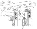
C.器具ドライバ及びインターフェース
システムのロボットアームのエンドエフェクタは、(i)医療器具を作動させるための電気機械的手段を組み込む器具ドライバ(代替的には、「器具駆動機構」又は「器具デバイスマニピュレータ」と呼ばれる)と、(ii)モータなどの任意の電気機械的構成要素を欠いていてもよい除去可能な又は取り外し可能な医療器具と、を含み得る。この二分法は、医療処置に使用される医療器具を滅菌する必要性、それらの複雑な機械的アセンブリ及び敏感な電子機器により、高価な資本設備を十分に滅菌することができないことに推進される可能性がある。したがって、医療器具は、医師又は医師のスタッフによる個々の滅菌又は廃棄のために、器具ドライバ(したがってそのシステム)から取り外し、除去、及び交換されるように設計することができる。対照的に、器具ドライバは交換又は滅菌される必要がなく、保護のために掛け布をすることができる。C. Instrument Driver and Interface The end effector of the robotic arm of the system includes (i) an instrument driver that incorporates electromechanical means for actuating a medical instrument (alternatively referred to as an "instrument drive mechanism" or "instrument device manipulator");); and (ii) removable or removable medical devices that may lack any electromechanical components such as motors. This dichotomy is driven by the need to sterilize medical instruments used in medical procedures, their complex mechanical assemblies and sensitive electronics, and the inability to adequately sterilize expensive capital equipment. there is a possibility. Accordingly, medical instruments can be designed to be removed, removed, and replaced from the instrument driver (and thus the system) for individual sterilization or disposal by the physician or physician's staff. In contrast, instrument drivers do not need to be replaced or sterilized and can be draped for protection.
図15は、例示的な器具ドライバを示す。ロボットアームの遠位端に配置される器具ドライバ62は、駆動シャフト64を介して医療器具に制御トルクを提供するために平行軸を伴って配置された1つ以上の駆動ユニット63を含む。各駆動ユニット63は、器具と相互作用するための個々の駆動シャフト64と、モータシャフトの回転を所望のトルクに変換するためのギヤヘッド65と、駆動トルクを生成するためのモータ66と、モータシャフトの速度を測定し、制御回路にフィードバックを提供するエンコーダ67と、制御信号を受信し、駆動ユニットを作動させるための制御回路68と、を備える。各駆動ユニット63は、独立して制御され電動化され、器具ドライバ62は、複数(図15に示すように4つ)の独立した駆動出力を医療器具に提供することができる。動作中、制御回路68は、制御信号を受信し、モータ66にモータ信号を送信し、エンコーダ67によって測定された得られたモータ速度を所望の速度と比較し、モータ信号を変調して所望のトルクを生成する。 FIG. 15 shows an exemplary instrument driver. An
無菌環境を必要とする処置のために、ロボットシステムは、器具ドライバと医療器具との間に位置する、滅菌ドレープに接続された滅菌アダプタなどの駆動インターフェースを組み込んでもよい。滅菌アダプタの主な目的は、器具ドライバの駆動シャフトから器具の駆動入力に角度運動を伝達する一方で、駆動シャフトと駆動入力との間の物理的分離、したがって無菌性を維持することである。したがって、例示的な滅菌アダプタは、器具ドライバの駆動シャフトと嵌合されることが意図された一連の回転入力及び出力と、器具に対する駆動入力とを含み得る。滅菌アダプタに接続される滅菌ドレープは、透明又は半透明プラスチックなどの薄い可撓性材料で構成され、器具ドライバ、ロボットアーム、及び(カートベースのシステムにおける)カート又は(テーブルベースのシステムにおける)テーブルなどの資本設備を覆うように設計される。ドレープの使用により、滅菌を必要としない領域(すなわち、非滅菌野)に依然として位置付けられている間に、資本設備を患者に近接して配置することが可能となる。滅菌ドレープの反対側では、医療器具は、滅菌(すなわち、滅菌野)を必要とする領域において患者とインターフェースしてもよい。 For procedures requiring a sterile environment, the robotic system may incorporate a drive interface, such as a sterile adapter connected to a sterile drape, located between the instrument driver and the medical instrument. The primary purpose of the sterile adapter is to transfer angular motion from the drive shaft of the instrument driver to the drive input of the instrument, while maintaining physical separation between the drive shaft and the drive input, and thus sterility. Accordingly, an exemplary sterilization adapter may include a series of rotational inputs and outputs intended to be mated with the drive shaft of the instrument driver and a drive input to the instrument. The sterile drape, which is connected to the sterile adapter, is constructed of a thin flexible material such as clear or translucent plastic and is connected to the instrument driver, the robotic arm, and the cart (in cart-based systems) or the table (in table-based systems). Designed to cover capital equipment such as The use of drapes allows capital equipment to be placed in close proximity to the patient while still being located in areas that do not require sterilization (ie, non-sterile fields). On the other side of the sterile drape, medical instruments may interface with the patient in the area requiring sterilization (ie, the sterile field).
D.医療器具
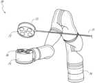
図16は、ペアの器具ドライバを備えた例示的な医療器具を示す。ロボットシステムと共に使用するために設計された他の器具と同様に、医療器具70は、細長いシャフト71(又は細長い本体)及び器具基部72を備える。医師による手動相互作用が意図されているその設計により「器具ハンドル」とも呼ばれる器具基部72は、一般に、ロボットアーム76の遠位端において器具ドライバ75上の駆動インターフェースを通って延びる駆動出力74と嵌合するように設計された、回転可能な駆動入力73、例えば、レセプタクル、プーリー、又はスプールを備えてもよい。物理的に接続、ラッチ、及び/又は結合されるときに、器具基部72の嵌合された駆動入力73は、器具ドライバ75における駆動出力74と回転軸線を共有して、駆動出力74から駆動入力73へのトルクの伝達を可能とすることができる。いくつかの実施形態では、駆動出力74は、駆動入力73上のレセプタクルと嵌合するように設計されたスプラインを備えてもよい。D. Medical Instrument FIG. 16 illustrates an exemplary medical instrument with a paired instrument driver. Like other instruments designed for use with robotic systems,
細長いシャフト71は、例えば、内視鏡におけるような解剖学的開口部若しくは管腔、又は、例えば、腹腔鏡検査におけるような低侵襲性切開部のいずれかを通して送達されるように設計される。細長いシャフト71は、可撓性(例えば、内視鏡と同様の特性を有する)若しくは剛性(例えば、腹腔鏡と同様の特性を有する)のいずれかであってもよく、又は可撓性部分及び剛性部分の両方のカスタマイズされた組み合わせを含んでもよい。腹腔鏡のために設計される場合、剛性の細長いシャフトの遠位端は、少なくとも1つの自由度を有するクレビスから形成された接合されたリストから延びるエンドエフェクタ、及び駆動入力が器具ドライバ75の駆動出力74から受け取ったトルクに応答して回転する際に、腱からの力に基づいて作動され得る、例えば、把持具又ははさみである、手術用ツール又は医療器具に接続することができる。内視鏡検査のために設計される場合、可撓性の細長いシャフトの遠位端は、器具ドライバ75の駆動出力74から受信したトルクに基づいて関節運動及び屈曲され得る操縦可能又は制御可能な屈曲部を含んでもよい。
器具ドライバ75からのトルクは、細長いシャフト71に沿った腱を使用して細長いシャフト71の下流に伝達される。プルワイヤなどのこれらの個々の腱は、器具ハンドル72内の個々の駆動入力73に個別に固定されてもよい。ハンドル72から、腱は、細長いシャフト71に沿って1つ以上のプルルーメン(pull lumen)に向けられ、細長いシャフト71の遠位部分、又は細長いシャフトの遠位部分のリストに固定される。腹腔鏡、内視鏡、又はハイブリッド処置などの外科処置中、これらの腱は、リスト、把持具、又ははさみなどの遠位に取り付けられたエンドエフェクタに連結されてもよい。このような構成の下で、駆動入力73に及ぼされるトルクは、腱に張力を伝達し、それによってエンドエフェクタを何らかの方法で作動させる。いくつかの実施形態では、外科処置中に、腱は、関節を軸の周りで回転させることができ、それによってエンドエフェクタを一方向又は別の方向に移動させる。代替的には、腱は、細長いシャフト71の遠位端で把持具の1つ以上のジョーに接続されてもよく、腱からの張力によって把持具は閉鎖される。 Torque from
内視鏡検査では、腱は、接着剤、制御リング、又は他の機械的固定を介して、細長いシャフト71に沿って(例えば、遠位端に)位置付けられている屈曲部又は関節運動部に結合されてもよい。屈曲部の遠位端に固定的に取り付けられる場合、駆動入力73に及ぼされるトルクは、腱の下流に伝達され、より軟質の屈曲部(関節運動可能部又は領域と呼ばれることがある)を屈曲又は関節運動させる。非屈曲部分に沿って、個々の腱を内視鏡シャフトの壁に沿って(又は内側に)指向する個々のプルルーメンを螺旋状又は渦巻状にして、プルワイヤにおける張力からもたらされる半径方向の力の釣り合いをとることが有利であり得る。螺旋の角度及び/又はそれらの間の間隔は、特定の目的のために変更又は設計することができ、よりきつい螺旋は負荷力の下でより少ないシャフト圧縮を示し、一方、より少ない量の螺旋は負荷力の下でより大きなシャフト圧縮をもたらすが、屈曲を制限する。スペクトルのもう一方の端部では、プルルーメンは、細長いシャフト71の長手方向軸に平行に指向されて、所望の屈曲部又は関節運動可能部における制御された関節運動を可能にしてもよい。 In endoscopy, the tendon is attached to a flexure or articulation section located along the elongate shaft 71 (e.g., at the distal end) via adhesive, control rings, or other mechanical fixation. May be combined. When fixedly attached to the distal end of the flexure, the torque exerted on
内視鏡検査では、細長いシャフト71は、ロボット処置を支援するいくつかの構成要素を収容する。シャフト71は、シャフト71の遠位端における手術領域に対して手術ツール(又は医療器具)を展開する、灌注する、及び/又は吸引するための作業チャネルを含んでもよい。シャフト71は、遠位先端部の光学アセンブリに/光学アセンブリから信号を伝送するためのワイヤ及び/又は光ファイバも収容してもよく、これは光学カメラを含んでもよい。シャフト71はまた、発光ダイオードなどの近位に位置する光源からシャフト71の遠位端に光を搬送するための光ファイバを収容してもよい。 In endoscopy, the
器具70の遠位端では、遠位先端部は、診断及び/又は治療、灌注、及び吸引のためにツールを手術部位に送達するための作業チャネルの開口部を備えてもよい。遠位先端部はまた、内部解剖学的空間の画像を捕捉するために、繊維スコープ又はデジタルカメラなどのカメラのためのポートを含んでもよい。関連して、遠位先端部はまた、カメラを使用するときに解剖学的空間を照明するための光源用のポートを含んでもよい。 At the distal end of
図16の例では、駆動シャフト軸、したがって駆動入力軸は、細長いシャフト71の軸に直交する。しかしながら、この配置は、細長いシャフト71のロール能力を複雑にする。駆動入力73を静止させながら、細長いシャフト71をその軸に沿ってロールさせることにより、腱が駆動入力73から延び、細長いシャフト71内のプルルーメンに入る際に、腱の望ましくない絡まりをもたらす。そのような腱の結果としての絡まりは、内視鏡処置中の可撓性の細長いシャフト71の動きを予測することを意図した制御アルゴリズムを混乱させる可能性がある。 In the example of FIG. 16, the drive shaft axis, and thus the drive input axis, is orthogonal to the axis of the
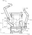
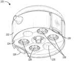
図17は、駆動ユニットの軸が器具の細長いシャフトの軸に平行である、器具ドライバ及び器具の代替的な設計を示す。示されるように、円形の器具ドライバ80は、ロボットアーム82の端部において平行に整合された駆動出力81を備える4つの駆動ユニットを含む。駆動ユニット及びそれらのそれぞれの駆動出力81は、アセンブリ83内の駆動ユニットのうちの1つによって駆動される器具ドライバ80の回転アセンブリ83内に収容される。回転駆動ユニットによって提供されるトルクに応答して、回転アセンブリ83は、回転アセンブリ83を器具ドライバ80の非回転部分84に接続する円形ベアリングに沿って回転する。電力及び制御信号は、ブラシ付きスリップリング接続(図示せず)による回転を通して維持され得る電気接点を介して、器具ドライバ80の非回転部分84から回転アセンブリ83に伝達されてもよい。他の実施形態では、回転アセンブリ83は、非回転可能部分84に一体化され、したがって他の駆動ユニットと平行ではない別個の駆動ユニットに応答してもよい。回転機構83は、器具ドライバ80が、器具ドライバ軸85周りの単一ユニットとして、駆動ユニット及びそれらのそれぞれの駆動出力81を回転させることを可能にする。 FIG. 17 shows an alternative design of the instrument driver and instrument in which the axis of the drive unit is parallel to the axis of the elongated shaft of the instrument. As shown, circular instrument driver 80 includes four drive units with
先に開示した実施形態と同様に、器具86は、細長いシャフト部分88と、器具ドライバ80内の駆動出力81を受容するように構成された複数の駆動入力89(レセプタクル、プーリー、及びスプールなど)を備えた器具基部87(説明目的のために透明な外部スキンで示される)と、を備えてもよい。先の開示された実施形態とは異なり、器具シャフト88は、器具基部87の中心から延び、軸は、図16の設計にあるように直交するのではなく、駆動入力89の軸に実質的に平行である。 Similar to previously disclosed embodiments,
器具ドライバ80の回転アセンブリ83に結合されると、器具基部87及び器具シャフト88を備える医療器具86は、器具ドライバ軸85を中心にして回転アセンブリ83と一緒に回転する。器具シャフト88は器具基部87の中心に位置付けられているため、器具シャフト88は、取り付けられたときに器具ドライバ軸85と同軸である。したがって、回転アセンブリ83の回転により、器具シャフト88は、それ自体の長手方向軸を中心に回転する。更に、器具基部87が器具シャフト88と共に回転すると、器具基部87内の駆動入力89に接続された任意の腱は、回転中に絡まらない。したがって、駆動出力81、駆動入力89、及び器具シャフト88の軸の平行性は、制御腱を絡めることなくシャフト回転を可能にする。 When coupled to
図18は、いくつかの実施形態による、器具ベースの挿入アーキテクチャを有する器具を示す。器具150は、上述の器具ドライバのいずれかに連結することができる。器具150は、細長いシャフト152と、シャフト152に接続されたエンドエフェクタ162と、シャフト152に連結されたハンドル170とを備える。細長いシャフト152は、近位部分154及び遠位部分156を有する管状部材を備える。細長いシャフト152は、その外側表面に沿った1つ以上のチャネル又は溝158を備える。溝158は、1つ以上のワイヤ又はケーブル180をそれを通して受容するように構成されている。したがって、1つ以上のケーブル180は、細長いシャフト152の外側表面に沿って延びる。他の実施形態では、ケーブル180は、細長いシャフト152を通って延びることもできる。いくつかの実施形態では、これらのケーブル180のうちの1つ以上の操作(例えば、器具ドライバを介して)により、エンドエフェクタ162の作動がもたらされる。 FIG. 18 illustrates an instrument having an instrument-based insertion architecture, according to some embodiments.
器具基部とも称され得る器具ハンドル170は、一般に、器具ドライバの取り付け面上で1つ以上のトルカプラと往復嵌合するように設計された1つ以上の機械的入力174、例えばレセプタクル、プーリー又はスプールを有する取り付けインターフェース172を備えることができる。いくつかの実施形態では、器具150は、細長いシャフト152がハンドル170に対して並進することを可能にする一連のプーリー又はケーブルを備える。換言すれば、器具150自体は器具の挿入を収容する器具ベースの挿入アーキテクチャを備え、それによって器具150の挿入を提供するためにロボットアームへの依存を最小化する。他の実施形態では、ロボットアームは、器具の挿入に大きく関与することができる。 The instrument handle 170, which may also be referred to as an instrument base, generally includes one or more
E.コントローラ
本明細書に記載の任意のロボットシステムは、ロボットアームに取り付けられた器具を操作するための入力デバイス又はコントローラを含むことができる。いくつかの実施形態では、コントローラは、器具と連結(例えば、通信的に、電子的に、電気的に、無線的に、及び/又は機械的に)することができ、それによりコントローラの操作は、例えば、マスタースレーブ制御を介して、器具の対応する操作を引き起こす。E. Controller Any robotic system described herein can include an input device or controller for operating instruments attached to a robotic arm. In some embodiments, the controller can be coupled (e.g., communicatively, electronically, electrically, wirelessly, and/or mechanically) with the instrument such that operation of the controller , for example via a master-slave control, triggering a corresponding operation of the instrument.
図19は、コントローラ182の実施形態の斜視図である。本実施形態では、コントローラ182は、インピーダンス制御及びアドミタンス制御の両方を有することができるハイブリッドコントローラを備える。他の実施形態では、コントローラ182は、インピーダンス又は受動的制御だけ利用することができる。他の実施形態では、コントローラ182は、アドミタンス制御だけ利用することができる。ハイブリッドコントローラであることにより、コントローラ182は、有利には、使用中、より低い知覚慣性を有することができる。 FIG. 19 is a perspective view of an embodiment of
図示される実施形態では、コントローラ182は、2つの医療器具の操作を可能にするように構成され、2つのハンドル184を含む。ハンドル184の各々は、ジンバル186に接続されている。各ジンバル186は位置付けプラットフォーム188に接続されている。 In the illustrated embodiment,
図19に示されるように、各位置付けプラットフォーム188は、プリズム接合部196によってカラム194に連結されたSCARAアーム(selective compliance assembly robot arm)198を含む。プリズム接合部196は、(例えば、レール197に沿って)カラム194に沿って並進するように構成され、ハンドル184のそれぞれがz方向に並進され、第1の自由度を提供するように構成されている。SCARAアーム198は、x-y平面におけるハンドル184の運動を可能にし、2つの更なる自由度を提供するように構成されている。 As shown in FIG. 19, each
いくつかの実施形態では、1つ以上のロードセルがコントローラ内に位置付けられる。例えば、いくつかの実施形態では、ロードセル(図示せず)は、ジンバル186の各々の本体内に位置付けられる。ロードセルを設けることによって、コントローラ182の一部分は、アドミタンス制御下で動作することができ、それによって、使用中にコントローラの知覚慣性を有利に低減する。いくつかの実施形態では、位置付けプラットフォーム188はアドミタンス制御用に構成され、一方、ジンバル186はインピーダンス制御用に構成されている。他の実施形態では、ジンバル186はアドミタンス制御用に構成され、位置付けプラットフォーム188はインピーダンス制御用に構成されている。したがって、いくつかの実施形態では、位置付けプラットフォーム188の並進又は位置自由度は、アドミタンス制御に依存することができ、一方、ジンバル186の回転自由度はインピーダンス制御に依存する。 In some embodiments, one or more load cells are positioned within the controller. For example, in some embodiments, a load cell (not shown) is positioned within the body of each
F.ナビゲーション及び制御
従来の内視鏡検査は、操作者である医師に腔内誘導を提供するために、蛍光透視法(例えば、Cアームを通して送達され得るような)、及び他の形態の放射線ベースの撮像モダリティの使用を伴うことがある。対照的に、本開示によって企図されるロボットシステムは、放射線への医師の暴露を低減し、手術室内の機器の量を低減するために、非放射線ベースのナビゲーション及び位置特定手段を提供することができる。本明細書で使用するとき、用語「位置特定」は、基準座標系内のオブジェクトの位置を判定及び/又は監視することを指すことがある。術前マッピング、コンピュータビジョン、リアルタイムEM追跡、及びロボットコマンドデータなどの技術は、放射線を含まない動作環境を達成するために個別に又は組み合わせて使用されてもよい。放射線ベースの撮像モダリティが依然として使用されるその他の場合、術前マッピング、コンピュータビジョン、リアルタイムEM追跡、及びロボットコマンドデータは、放射線ベースの撮像モダリティによってのみ取得される情報を改善するために、個別に又は組み合わせて使用されてもよい。F. Navigation and Control Traditional endoscopy uses fluoroscopy (such as can be delivered through a C-arm), and other forms of radiation-based May involve the use of imaging modalities. In contrast, robotic systems contemplated by the present disclosure may provide non-radiation-based navigation and localization means to reduce physician exposure to radiation and reduce the amount of equipment within the operating room. can. As used herein, the term "localization" may refer to determining and/or monitoring the position of an object within a reference coordinate system. Techniques such as preoperative mapping, computer vision, real-time EM tracking, and robot command data may be used individually or in combination to achieve a radiation-free operating environment. In other cases where radiation-based imaging modalities are still used, pre-operative mapping, computer vision, real-time EM tracking, and robotic command data can be used individually to improve the information obtained only by radiation-based imaging modalities. Or they may be used in combination.
図20は、例示的な実施形態にかかる、器具の位置など、ロボットシステムの1つ以上の要素の位置を推定する位置特定システム90を示すブロック図である。位置特定システム90は、1つ以上の命令を実行するように構成されている1つ以上のコンピュータデバイスのセットであってもよい。コンピュータデバイスは、上で考察された1つ以上の構成要素内のプロセッサ(又は複数のプロセッサ)及びコンピュータ可読メモリによって具現化されてもよい。例として、限定するものではないが、コンピュータデバイスは、図1に示されるタワー30、図1~図4に示されるカート11、図5~図14に示されるベッドなどの形態であってよい。 FIG. 20 is a block diagram illustrating a
図20に示されるように、位置特定システム90は、入力データ91~94を処理して医療器具の遠位先端部の位置データ96を生成する位置特定モジュール95を含んでもよい。位置データ96は、基準系に対する器具の遠位端の場所及び/又は配向を表すデータ又は論理であってもよい。基準系は、患者の解剖学的構造、又はEM場発生器(EM場発生器についての以下の考察を参照)などの既知の物体に対する基準系とすることができる。 As shown in FIG. 20,
ここで、様々な入力データ91~94についてより詳細に説明する。術前マッピングは、低用量CTスキャンの収集を利用して達成することができる。術前CTスキャンは、例えば、患者の内部解剖学的構造の断面図の「スライス」として可視化される3次元画像へと再構成される。全体として分析される場合、患者の肺網などの患者の解剖学的構造の解剖学的空腔、空間、及び構造のための画像ベースのモデルが生成され得る。中心線形状(center-line geometry)などの手法をCT画像から決定及び近似して、モデルデータ91(術前CTスキャンのみを使用して生成された場合は「術前モデルデータ」とも称される)と称される患者の解剖学的構造の3次元ボリュームを作成することができる。中心線形状の使用は、米国特許出願第14/523,760号で考察されており、その内容はその全体が本明細書に組み込まれる。ネットワーク位相モデルもまた、CT画像から導出されてもよく、気管支鏡検査に特に適している。 Here, various input data 91-94 will be explained in more detail. Preoperative mapping can be accomplished using acquisition of low-dose CT scans. Preoperative CT scans, for example, are reconstructed into three-dimensional images that are visualized as cross-sectional "slices" of the patient's internal anatomy. When analyzed as a whole, an image-based model may be generated for the anatomical cavities, spaces, and structures of the patient's anatomy, such as the patient's pulmonary meshwork. Methods such as center-line geometry are determined and approximated from CT images to generate model data 91 (also referred to as "preoperative model data" when generated using only preoperative CT scans). ) can create a three-dimensional volume of the patient's anatomy. The use of centerline shapes is discussed in US patent application Ser. No. 14/523,760, the contents of which are incorporated herein in their entirety. Network phase models may also be derived from CT images and are particularly suitable for bronchoscopy.
いくつかの実施形態では、器具はカメラを装備して、視覚データ(又は画像データ)92を提供してもよい。位置特定モジュール95は、視覚データ92を処理して、1つ以上の視覚ベースの(又は画像ベースの)位置追跡モジュール又は機能を有効にしてもよい。例えば、術前モデルデータ91は、医療器具(例えば、内視鏡又は内視鏡の作業チャネルを通って前進する器具)のコンピュータビジョンベースの追跡を可能にするために、視覚データ92と共に使用されてもよい。例えば、術前モデルデータ91を使用して、ロボットシステムは、内視鏡の予想される移動経路に基づいて、モデルから、予測される内視鏡画像のライブラリを生成することができ、各画像はモデル内の位置にリンクされる。手術中に、このライブラリは、カメラ(例えば、内視鏡の遠位端でのカメラ)で捕捉されたリアルタイム画像を画像ライブラリ内のものと比較して、位置特定を支援するために、ロボットシステムによって参照することができる。 In some embodiments, the instrument may be equipped with a camera to provide visual data (or image data) 92.
他のコンピュータビジョンベースの追跡技術は、カメラの動き、したがって内視鏡を判定するための特徴追跡を使用する。位置特定モジュール95のいくつかの特徴は、解剖学的管腔に対応する術前モデルデータ91内の円形幾何学形状を特定し、どの解剖学的管腔が選択されたか、並びにカメラの相対的な回転及び/又は並進運動を判定するために、それらの幾何学的形状の変化を追跡してもよい。位相マップの使用は、視覚ベースのアルゴリズム又は技術を更に向上させることがある。 Other computer vision-based tracking techniques use feature tracking to determine camera movement and, therefore, the endoscope. Several features of the
光学フロー、別のコンピュータビジョンベースの技術は、カメラの動きを推測するために、視覚データ92内のビデオシーケンス内の画像ピクセルの変位及び並進を分析してもよい。光学フロー技術の例としては、動き検出、オブジェクトセグメンテーション計算、輝度、動き補償符号化、立体視差測定などを挙げることができる。複数の反復にわたり多数のフレームを比較することにより、カメラ(及びしたがって内視鏡)の移動及び位置を判定することができる。 Optical flow, another computer vision-based technique, may analyze displacements and translations of image pixels within a video sequence within
位置特定モジュール95は、リアルタイムEM追跡を使用して、術前モデルによって表される患者の解剖学的構造に整合され得るグローバル座標系内に、内視鏡のリアルタイム位置を生成することができる。EM追跡では、医療器具(例えば、内視鏡器具)内の1つ以上の位置及び向きに埋め込まれた1つ以上のセンサコイルを含むEMセンサ(又はトラッカー)は、既知の位置に位置付けされた1つ以上の静的EM場発生器によって生成されるEM場の変動を測定する。EMセンサによって検出された位置情報は、EMデータ93として記憶される。EM場発生器(又は送信機)は、埋め込まれたセンサが検出し得る低強度磁場を生成するために、患者に近接して配置することができる。磁場はEMセンサのセンサコイル内に小さな電流を誘導し、EMセンサとEM場発生器との間の距離及び角度を判定するためにこの電流が分析され得る。これらの距離及び向きは、患者の解剖学的構造の術前モデル内の位置と座標系内の単一の位置を整合する幾何学的変換を判定するために、患者の解剖学的構造(例えば、術前モデル)に術中「登録」され得る。一旦登録されると、医療器具の1つ以上の位置(例えば、内視鏡の遠位先端部)に埋め込まれたEMトラッカは、患者の解剖学的構造を通る医療器具の進行のリアルタイム表示を提供することができる。 The
ロボットコマンド及び運動学データ94はまた、ロボットシステムのための位置特定データ96を提供するために、位置特定モジュール95によって使用されてもよい。関節運動コマンドから生じるデバイスピッチ及びヨーは、術前較正中に判定され得る。術中、これらの較正測定値は、既知の挿入深度情報と組み合わせて使用されて、器具の位置を推定し得る。あるいは、これらの計算は、ネットワーク内の医療器具の位置を推定するために、EM、視覚、及び/又は位相モデリングと組み合わせて分析することができる。 Robot commands and
図20が示すように、いくつかの他の入力データは、位置特定モジュール95によって使用することができる。例えば、図20には示されていないが、形状検知繊維を利用する器具は、位置特定モジュール95が器具の位置及び形状を判定するために使用することができる形状データを提供することができる。 As FIG. 20 shows, several other input data may be used by
位置特定モジュール95は、入力データ91~94を組み合わせて(複数可)使用することができる。場合によっては、このような組み合わせは、位置特定モジュール95が入力データ91~94の各々から判定された位置に信頼重みを割り当てる確率的アプローチを使用し得る。したがって、EMデータが信頼でき得ない場合(EM干渉が存在する場合など)、EMデータ93によって判定された位置の信頼性を低下させることができ、位置特定モジュール95は、視覚データ92並びに/又はロボットコマンド及び運動学データ94により重く依存してもよい。
上で考察されるように、本明細書で考察されるロボットシステムは、上記の技術のうちの1つ以上の組み合わせを組み込むように設計することができる。タワー、ベッド、及び/又はカートに基づいているロボットシステムのコンピュータベースの制御システムは、例えば、永続的な磁気記憶ドライブ、ソリッドステートドライブなどの非一時的コンピュータ可読記憶媒体内に、コンピュータプログラム命令を記憶してもよく、コンピュータプログラム命令は、実行されると、システムに、センサデータ及びユーザコマンドを受信及び分析させ、システム全体の制御信号を生成させ、グローバル座標系内の器具の位置、解剖学的マップなどのナビゲーション及び位置特定データを表示させる。 As discussed above, the robotic systems discussed herein can be designed to incorporate a combination of one or more of the above techniques. Computer-based control systems for tower, bed, and/or cart-based robotic systems store computer program instructions in non-transitory computer-readable storage media, such as, for example, permanent magnetic storage drives, solid-state drives, etc. The computer program instructions, which may be stored and, when executed, cause the system to receive and analyze sensor data and user commands, generate system-wide control signals, determine the position of the instrument in a global coordinate system, and the anatomy. Display navigation and location data such as target maps.
2.医療器具のドッキング
本開示の実施形態は、医療器具をドッキングするための装置、システム、及び技術に関する。いくつかのロボット制御可能な医療器具は、ロボット医療システムの追加の構成要素とドッキングすることができる基部又はハンドルを含む。一例として、ロボット制御可能な内視鏡は、ロボットアーム上の器具駆動機構(IDM)とドッキングされるように構成された基部又はハンドルを含み得る。器具駆動機構は、医療器具の対応する駆動入力と係合して、医療器具の制御を容易にかつ有効にする駆動出力を含むことができる。いくつかの実施形態では、本明細書に開示されるシステム及び技術は、器具駆動機構の駆動出力と医療器具の駆動入力との間の整合を容易にするように構成される。駆動出力を駆動入力と整合させることにより、医療器具を器具駆動機構にドッキングすることを容易にすることができる。例えば、駆動出力及び駆動入力を整合させることにより、医療器具を器具駆動機構にすばやく容易にドッキングすることができる。本明細書に記載されるシステム及び技術は、例えば、図1~図20を参照して上述したもの並びに以下に記載されるもの及び他のロボットシステムなどのロボット制御可能な医療システムと共に使用することができる。例示的な医療器具及び器具駆動機構は、例えば、図15~図18を参照して上述及び以下に記載されている。2. Docking Medical Devices Embodiments of the present disclosure relate to devices, systems, and techniques for docking medical devices. Some robotically controllable medical instruments include a base or handle that can be docked with additional components of a robotic medical system. As an example, a robotically controllable endoscope may include a base or handle configured to dock with an instrument drive mechanism (IDM) on a robotic arm. The instrument drive mechanism can include a drive output that engages a corresponding drive input of the medical instrument to facilitate and enable control of the medical instrument. In some embodiments, the systems and techniques disclosed herein are configured to facilitate alignment between a drive output of an instrument drive mechanism and a drive input of a medical instrument. By matching the drive output with the drive input, docking of the medical instrument to the instrument drive mechanism can be facilitated. For example, by matching the drive output and drive input, a medical instrument can be quickly and easily docked to the instrument drive mechanism. The systems and techniques described herein may be used with robotically controllable medical systems, such as those described above with reference to FIGS. 1-20 and those described below, and other robotic systems. I can do it. Exemplary medical instruments and instrument drive mechanisms are described above and below with reference to, for example, FIGS. 15-18.
ロボット医療処置中に図16に示されるように、医療器具70は、ロボットアーム76上に位置付けられ得る器具駆動機構75にドッキングされ得る。医療器具70は、器具駆動機構75と係合するように構成された器具ベース又はハンドル72を含み得る。図示のように、器具ハンドル72は、器具駆動機構75上の対応する駆動出力74と係合するように構成された複数の駆動入力73を含むことができる。駆動入力及び駆動出力の詳細な例示的実施形態を以下に記載される図21A~図23に示す。上述したように、駆動出力74は、器具駆動機構75内のモータによって駆動され得る(図15を参照)。駆動出力74は、モータの回転(又は他の運動)を駆動入力75に伝達して、医療器具70の細長いシャフト71の関節運動、又は細長いシャフト71の遠位端に位置付けられたツールの作動など、医療器具70の様々な機能を制御することができる。器具ハンドル72は、処置中に使用するために医療器具70を保持するために器具駆動機構75にラッチすることができる。 As shown in FIG. 16 during a robotic medical procedure, a
医療器具70を器具駆動機構75にドッキングしようとするとき、器具ハンドル72の駆動入力73及び器具駆動機構75の駆動出力74は整合されなくてもよい。駆動入力73及び駆動出力74の位置ずれは、医療器具70を器具駆動機構75にドッキングすることが困難又は不可能であり得る。医療器具70が器具駆動機構75にドッキングするために、駆動出力74又は駆動入力73は、適切に整合されるまで回転される必要があり得る。 When attempting to dock the
駆動出力74及び駆動入力73を整合させることができるいくつかの方法がある。例えば、いくつかの実施形態では、器具駆動機構75は、モータが駆動可能に戻るように構成されてもよい。このような実施形態では、医療器具70を器具駆動機構75にドッキングする力は、駆動出力74が駆動入力73と適切に整合するまで駆動出力74を回転させるのに十分であり得る。しかしながら、いくつかの実施形態では、これは、モータのいずれの抵抗も、それらが後方駆動されるときに克服されなければならないため、著しい力を必要とする場合がある。同様に、いくつかの実施形態では、器具駆動機構75内のモータは、駆動出力74が駆動入力73と整合するまで回転することを可能にするために、ドッキング中にオフにされてもよい。これらの実施形態によって提供される性能は、調整可能であってもよい。例えば、駆動出力74を回転させるのに必要なトルクは、調整可能であってもよい。 There are several ways in which drive
別の例として、いくつかの実施形態では、ドッキング中に印加される力は、器具駆動機構75の駆動出力74と適切に整合するまで、医療器具70上の駆動入力73を回転させることができる。医療器具70のいくつかの実施形態は、予め張力をかけられていない駆動入力73によって作動されるプルワイヤを含んでもよい。予め張力をかけられたプルワイヤを含まない医療器具70では、駆動入力73は、自由運動に対するいくらかの許容差を有し得る。すなわち、予め張力をかけられたプルワイヤを含まない医療器具70では、プルワイヤを作動させることなく、駆動入力73(少なくともある程度の回転)を回転させることが可能であり得る。したがって、いくつかの実施形態では、駆動入力73が駆動出力74とずれているとき、駆動入力73は、ドッキング中にこの許容範囲内でそれ自体を調整するように回転し得る。 As another example, in some embodiments, the force applied during docking may rotate the
医療器具70の他の実施形態は、予め張力をかけられたプルワイヤを含んでもよい。これらの器具のいくつかの実施形態(予め張力をかけられたプルワイヤを含む)では、駆動入力73の任意の回転は、プルワイヤの対応する作動を引き起こすことができる。例えば、張力をかけられたプルワイヤが器具70の細長いシャフト71の関節運動を引き起こすように構成されている場合、駆動入力73の任意の回転は、細長いシャフト71の関節運動を引き起こすことになる。これらの実施形態では、駆動入力73を自由に回転させて、ドッキング中の整合を容易にすることが望ましくない場合がある。例えば、この回転によって細長いシャフト71を関節運動させ得るため、駆動入力73がドッキング中に自由に回転することを可能にすることは望ましくない場合があり、これは、医療器具70の細長いシャフト71がドッキング中に真っ直ぐに維持されることが望ましい場合があるため許容できない。したがって、駆動出力74を自動的に調整して駆動入力75と整合させる方法が望ましい場合がある。そのような方法の実施例が、以下でより詳しく述べられる。 Other embodiments of
いくつかの実施形態では、器具駆動機構75は、駆動出力74に印加されるトルク又は力を感知するように構成されたセンサを含むことができる。駆動出力74及び駆動入力73がずれている場合、医療器具70のドッキング中、駆動入力73は、医療器具70及び器具駆動機構75が一緒になったときに、駆動出力74に接触して押し当ててもよい。ずれ中に経験される駆動出力74と駆動入力73との間のこの接触は、センサの出力に基づいて決定することができる。例えば、ずれは、センサによって測定され得る駆動入力73によって駆動出力74にトルクを付与させることができる。測定されたトルクは、駆動出力74及び駆動入力73がずれているという指示を提供することができる。いくつかの実施形態では、システムは、駆動出力74に関連付けられたモータを起動させて、駆動出力74を回転させることができる。駆動出力74は、駆動入力73と整合するまで回転することができる。いくつかの実施形態では、システムは、駆動出力74に付与された測定されたトルクがゼロに減少又は低下するときに、駆動出力74が駆動入力73と整合されると判定する。これが発生すると、システムは駆動出力74の回転を停止することができる。 In some embodiments,
したがって、いくつかの実施形態では、システムは、駆動出力74に関連付けられたセンサによって測定されたトルク又は力に応答して、駆動出力74を駆動入力73と自動的に整合させるように構成されてもよく、トルクは、駆動出力74と駆動入力73との位置ずれによって引き起こされる。これは、医療器具70の器具駆動機構75へのドッキングを有利に促進することができる。いくつかの実施形態では、これは、駆動出力74に関連付けられたモータを後方駆動する必要なく、駆動入力73との駆動出力74の整合を有利に可能にする。更に、いくつかの実施形態では、駆動入力73の回転を必要とせずに、駆動出力74と駆動入力73との整合を有利に可能にする。したがって、いくつかの実施形態では、本明細書に記載される自動整合システムは、予め張力をかけられたプルワイヤを含む医療器具と共に有利に使用され得る。 Accordingly, in some embodiments, the system is configured to automatically align
開示されるシステム及び方法のこれら及び他の特徴及び利点は、図21A~図29に示される実施例及び実施形態を参照して以下でより詳細に説明する。これらの実施例及び実施形態は、例示として提供され、本開示を限定することを意図するものではない。 These and other features and advantages of the disclosed systems and methods are described in more detail below with reference to the examples and embodiments shown in FIGS. 21A-29. These examples and embodiments are provided by way of illustration and are not intended to limit the disclosure.
図21A及び図21Bは、医療器具の対応する複数の駆動入力に係合するように構成された複数の駆動出力208を含む器具駆動機構200の実施形態の等角図及び端面図をそれぞれ示す。図示されるように、器具駆動機構200は、ハウジング202を含むことができる。ハウジング202は、医療器具にドッキングするように構成された取り付け面204を含むことができる。器具駆動機構200は、ドッキングされたときに医療器具を器具駆動機構200に固定するラッチ機構206を含むことができる。 21A and 21B illustrate isometric and end views, respectively, of an embodiment of an
図21A~図21Bに示されるように、器具駆動機構200は、駆動出力208を含むことができる。駆動出力208は、例えば、ハウジング内に位置付けされたモータによって駆動されるように構成された回転可能な要素であってもよい。図示した実施形態では、駆動出力208は、取り付け面204から突出するスプライン又はギヤとして構成されているが、駆動出力208の他の構成も可能である。例えば、駆動出力208は、取り付け面204内に凹部として形成されたレセプタクル又はソケットを備えることができる。駆動出力208は、医療器具上の対応する駆動入力と結合し、これに係合するように構成されている。駆動出力208は、器具駆動機構208内のモータから医療器具の駆動入力に回転運動(又は実施形態に応じた他の運動)を伝達することにより、処置中にモータを使用して医療器具を制御することができる。 As shown in FIGS. 21A-21B,
いくつかの実施形態では、器具駆動機構200は、通信モジュール210などの追加の機構を含み得る。通信モジュール210は、器具駆動機構200にドッキングされた医療器具から情報を読み取るように構成され得る。いくつかの実施形態では、通信モジュール210(又は器具駆動機構200のいくつかの他の部分)は、1つ以上の近接センサを備える。近接センサは、医療器具が器具駆動機構であるか、又は器具駆動機構にドッキングされているかを判定するように構成されてもよい。近接センサは、例えば、1つ以上の磁気近接センサを備えてもよい。 In some embodiments,
図22A及び図22Bは、器具駆動機構200の対応する複数の駆動出力208に係合するように構成された複数の駆動入力228を含む医療器具の器具ハンドル220の実施形態の等角図及び端面図をそれぞれ示す。示されるように、器具ハンドル220はハウジング222を含むことができる。ハウジング222は、器具駆動機構200の取り付け面204にドッキングするように構成された取り付け面224を含むことができる。器具ハンドル220は、ドッキングされたときに器具ハンドル220を器具駆動機構200に固定するラッチ機構226を含むことができる。 22A and 22B show isometric and end views of an embodiment of an
図22A~図22Bに示されるように、器具ハンドル220は駆動入力228を含むことができる。駆動入力228は、器具駆動機構200の駆動出力208によって駆動されるように構成された回転可能要素であってもよい。図示した実施形態では、駆動入力228は、取り付け面224内に凹んでいるレセプタクル又はソケットとして構成されているが、駆動入力228のための他の構成も可能である。例えば、駆動入力228は、取り付け面224から延びる突出スプライン又はギヤを備えることができる。 As shown in FIGS. 22A-22B, the instrument handle 220 can include a
いくつかの実施形態では、器具ハンドル220は、器具駆動機構200の通信モジュール210に情報を送信するように構成され得る通信モジュール230などの追加の機構を含むことができる。いくつかの実施形態では、通信モジュール230(又は器具ハンドル220のいくつかの他の部分)は、1つ以上の近接センサを備える。近接センサは、医療器具が器具駆動機構200であるか又は器具駆動機構200にドッキングされているかどうかを判定するように構成されてもよい。近接センサは、1つ以上の磁気近接センサを備えてもよい。 In some embodiments, the instrument handle 220 may include additional mechanisms, such as a
図23は、器具ハンドル220の器具駆動機構200へのドッキング中に駆動入力228に係合する器具駆動出力208の実施形態の斜視図を示す。図示のように、駆動出力208は、駆動入力229の対応する溝229内に受容されるように構成された歯209(例えば、隆起部、突出部、切欠き部、窪みなど)を備えてもよい。図示された例では、歯209及び溝229は相互作用して回転運動を伝達する。 FIG. 23 shows a perspective view of an embodiment of
以下に説明する実施例の多くでは、駆動出力208は歯209を含むギヤとして示され、駆動入力228は、溝229を含むソケットとして構成される。しかしながら、これは、全ての実施形態に当てはまる必要はなく、駆動出力208と駆動入力228との間で回転運動を伝達するための多くの他の構造的構成が可能である。例えば、いくつかの実施形態では、駆動出力208はソケットを備えてもよく、駆動入力228は、ソケット内に受容されるように構成されたギヤを備えることができる。別の例として、いくつかの実施形態では、駆動出力208及び駆動入力228の両方は、互いに噛み合うように構成されたギヤとして構成され得る。説明を容易にするために、以下の実施例は、ギヤとしての駆動出力208及び駆動入力228をソケットとして説明及び例示し続けるが、これは例示として行われ、特定の例示された構造的配置に本開示を限定することを意図するものではないことを理解する。他の実施形態では、駆動出力208及び駆動入力228は、直線運動などの他の種類の運動を伝達するように構成され得る。 In many of the embodiments described below,
図24は、駆動出力208が駆動入力228と整合されている例の図を示す。図示のように、整合されると、駆動出力208の歯209は、駆動入力228の溝229内に受容されてもよい。いくつかの実施形態では、歯209が溝229内で整合されるため、駆動入力228は、駆動出力208にいかなるトルク又は力も付与しないか、又はその逆である。これは、駆動入力228と駆動出力208との間の所望の整合を表すことができる。図示された整合はまた、整合されると、駆動出力208が駆動入力228内に容易に受容され得るため、器具駆動機構への医療器具のドッキングを容易にし得る。 FIG. 24 shows a diagram of an example in which drive
図25A~図25Dは、医療器具の器具駆動機構へのドッキング中に駆動出力208を駆動入力228と整合させるために使用され得る例示的な整合プロセスを示す。図25A~図25Cは、プロセス中の様々な段階における駆動出力208及び駆動入力228の例示的な図を示し、図25Dは、プロセス中の駆動出力208に関連付けられたトルクセンサの出力を示す例示的なグラフを示す。 25A-25D illustrate an example alignment process that may be used to align
図25Aに示されるように、多くの場合、医療器具を器具駆動機構にドッキングしようとするとき、器具駆動機構の1つ以上の駆動出力208、及び医療器具の1つ以上の駆動入力228は、適切に整合されない。例えば、駆動出力208の歯209は、図25Aに示すように、駆動入力228の溝229とずれてもよい。これが発生すると、医療器具及び器具駆動機構が完全に合体されるのを防ぐことができるため、医療器具を器具駆動機構に完全にドッキングすることは困難であり得る。したがって、駆動出力208及び駆動入力228を整合させることが望ましい場合がある。 As shown in FIG. 25A, often when attempting to dock a medical instrument to an instrument drive mechanism, one or
ずれているとき、駆動入力228は、図示のようにトルクτを作り出す力を駆動出力208に付与することができる。トルクτは、医療器具が器具駆動機構に向かってもたらされる際に、溝229の壁が歯209の壁に接触して押圧されることによって引き起こされてもよい。このことは、医療器具が予め張力をかけられたプルワイヤを含む実施形態において、特に当てはまる可能性があり、そのような医療器具では、駆動入力228は自由に回転することができない場合があるためである。また、いくつかの実施形態では、駆動出力208に関連付けられたモータは、駆動出力208が自由に回転することを可能にしなくてもよく、したがって、ずれた駆動出力208と駆動入力228との間の接触は、示されるようにトルクτを発生させることができる。トルクτを示す信号は、駆動出力208に関連付けられたセンサ(トルク又は力センサなど)によって感知又は測定することができる。図25Aでは、トルクτは時計回りの方向を有するように示されているが、これは全ての実施形態ではケースである必要はない。例えば、トルクτは、駆動出力208及び駆動入力228がどのようにずれているかに応じて反時計回り方向を有し得る。 When misaligned, drive
トルクτに基づいて図25Bに示すように、駆動出力208は、駆動出力208を駆動入力228と整合させるように、トルクτの方向と同じ回転方向Rに回転され得る。図25Bに示す段階では、駆動出力208は時計回り方向に回転されている。図25Bに示すように、駆動出力208は依然として駆動入力228とずれている。しかしながら、回転Rにより、(図25Aと比較して)ずれが減少する。回転Rは、本出願全体を通して論じられるように、測定されたトルクτに応答して、駆動出力208に関連付けられたモータによって駆動され得る。 As shown in FIG. 25B based on torque τ, drive
図25Cに示すように、駆動出力208の回転Rは、駆動出力208が駆動入力228と整合するまで継続することができる。この段階では、図25Cに示すように、駆動出力208と駆動入力228とが整合されるため、トルクτは駆動出力208に付与されなくなる。図示のように、整合されると、駆動出力208の歯209は、駆動入力228の溝229と整合され得る。駆動出力208の歯209は、駆動入力228の溝229と整合されているため、駆動入力228はトルクτを付与しなくてもよい。これは、駆動出力208の回転を停止するようにモータをトリガすることができる。駆動出力208及び駆動入力228が整合されると、医療器具の器具駆動機構へのドッキングが促進され得る。 As shown in FIG. 25C, rotation R of
図25Dは、図25A~図25Cに示されるドッキング及び整合プロセス中の、駆動出力208に関連付けられたトルク又は力センサの出力の例示的なグラフを示す。図示した実施形態では、グラフは、測定されたトルクを示しているが、これは全ての実施形態ではそうである必要はない。例えば、グラフは、測定された力若しくはトルク、又はトルク若しくは力を示すセンサの出力を表すことができる。 FIG. 25D shows an example graph of the output of a torque or force sensor associated with
図25Dに示すように、最初に、測定されたトルクτは実質的にゼロである。これは、医療器具が器具駆動機構に接触していない状態を表すことができる。この状態では、駆動出力208に関連付けられたトルクセンサがトルクを測定しないように、駆動出力208に接触していない。図示されるように、測定されたトルクは、ずれた駆動出力208が駆動入力228に接触し始めることができるため、測定トルクは、ドッキング中に器具駆動機構と接触すると、上昇し始めることができる。 Initially, the measured torque τ is substantially zero, as shown in FIG. 25D. This may represent a condition in which the medical instrument is not in contact with the instrument drive mechanism. In this state, the torque sensor associated with
図25Aに示す状態を表すことができる図25Dに示す時間taでは、トルクτは上昇しているが、閾値τthresh未満である。いくつかの実施形態では、測定されたトルクτは閾値τthresh未満のままであるが、駆動出力208の回転はトリガされない。閾値τthreshは、ノイズを考慮し、システムの感度を調整するように選択されてもよい。At timet a shown in FIG. 25D, which can represent the situation shown in FIG. 25A, the torque τ is increasing but below the threshold τthresh . In some embodiments, the measured torque τ remains below the threshold τthresh but rotation of the
時間taから、測定されたトルクτは閾値τthreshを超えて増加し続けることができる。測定されたトルクτが閾値τthreshを超えると、駆動出力208の回転Rがトリガされ得る。例えば、時間tbは、図25Bに示される段階を示し得、上述のように、駆動出力208が依然として駆動入力228とずれており、測定されたトルクτが依然として存在し、駆動出力208が駆動出力208を駆動入力228と整合させるように回転Rを受けている。From timeta , the measured torque τ may continue to increase beyond the threshold τthresh . When the measured torque τ exceeds a threshold τthresh , rotation R of the
図25Dに時間tbから示されるように、測定されたトルクτは、測定されたトルクτが閾値τthreshを下回るまで減少し続ける。測定されたトルクτが閾値τthreshを下回るとき、駆動出力208及び駆動入力228は、ここで、時間tcを示すことができる図25Cに示されるように整合されるので、回転Rは停止し得る。時間tcは、例えば、図25Cに示すような適切な整合に対応することができる。As shown in FIG. 25D from timetb , the measured torque τ continues to decrease until the measured torque τ falls below the threshold τthresh . When the measured torque τ is below the threshold τthresh , the rotation R stops because the
図26は、医療器具314の駆動入力318と器具駆動機構306の駆動出力312を整合させるように構成された医療システム300の実施形態を示すブロック図である。いくつかの実施形態では、整合は、図25A~図25Dを参照して説明され、図27を参照して以下でより詳細に説明したものと同様の方法で、駆動出力312に関連付けられたトルク又は力センサ308の出力に基づいて自動的に発生してもよい。 FIG. 26 is a block diagram illustrating an embodiment of a
図26に示すように、システム300は、プロセッサ302と通信する1つ以上のプロセッサ302及び1つ以上のコンピュータ可読媒体又はメモリ304を含み得る。メモリ304は、様々な特徴を実行するようにプロセッサ302を構成される命令を備えて構成されてもよい。例えば、メモリ304は、プロセッサ302に、出願全体にわたって記載された自動整合及びドッキング機構を実行させる命令で構成することができる。 As shown in FIG. 26,
システム300はまた、器具駆動機構306を含む。例示的な器具駆動機構は、例えば、図15、図16、図21A及び図21Bを参照して上述されている。いくつかの実施形態では、器具駆動機構306は、ロボットアーム又は他の器具位置付け装置の遠位端上に位置付けられる。器具駆動機構306は、医療器具314とドッキングするように構成され得る。図示した実施形態では、器具駆動機構306は、トルクセンサ308、モータ310及び駆動出力312を含む。器具駆動機構306はまた、図26に図示されていない追加の機構(例えば、近接センサ、通信モジュールなど)を含んでもよい。
前述したように、駆動出力312は、医療器具314上の対応する駆動入力318と係合するように構成され得る。駆動出力312は、モータ310によって駆動され得る。モータ310は、駆動出力312を、例えば、時計回り及び反時計回りの方向に回転させるように構成され得る。駆動出力312は、モータ310の回転運動を医療器具314の駆動入力318に伝達するように構成され得る。そのため、駆動出力312は、例えばギヤ及びソケットなどの回転運動を伝達するのに好適な任意の構造を含むことができる。 As previously discussed, drive output 312 may be configured to engage a corresponding drive input 318 on medical instrument 314. Drive output 312 may be driven by motor 310 . Motor 310 may be configured to rotate drive output 312 in, for example, clockwise and counterclockwise directions. Drive output 312 may be configured to transmit rotational motion of motor 310 to drive input 318 of medical instrument 314. As such, drive output 312 may include any structure suitable for transmitting rotational motion, such as gears and sockets.
図26に示すように、器具駆動機構306はまた、図示されたトルクセンサ308などのセンサ308を含むことができる。前述したように、力センサなどの他の種類のセンサも使用されてもよい。トルクセンサ308は、駆動出力312と関連付けることができる。例えば、トルクセンサ308は、駆動出力312に付与されたトルク又は力を示す出力信号を提供してもよい。いくつかの実施形態では、トルクセンサ308は、1つ以上のひずみゲージを含み得る。トルクセンサは、器具駆動機構306のハウジングとモータ310との間に位置付けするがでこときる。いくつかの実施形態では、トルクセンサ308は双方向である。つまり、いくつかの実施形態では、トルクセンサ308は、時計回り及び反時計方向の両方でトルクを測定するように構成されてもよい。トルクセンサ308の出力信号は、駆動出力312に付与されたトルクの方向を示すことができる。 As shown in FIG. 26, the instrument drive mechanism 306 can also include a sensor 308, such as the illustrated torque sensor 308. As previously mentioned, other types of sensors may also be used, such as force sensors. Torque sensor 308 can be associated with drive output 312. For example, torque sensor 308 may provide an output signal indicative of torque or force applied to drive output 312. In some embodiments, torque sensor 308 may include one or more strain gauges. A torque sensor may be located between the housing of instrument drive mechanism 306 and motor 310. In some embodiments, torque sensor 308 is bidirectional. That is, in some embodiments, torque sensor 308 may be configured to measure torque in both clockwise and counterclockwise directions. The output signal of torque sensor 308 can indicate the direction of torque applied to drive output 312.
図示のように、トルクセンサ308及びモータ310は、プロセッサ302に通信可能に連結され得る。これにより、例えば、トルクセンサ308の出力信号がプロセッサ302によって使用されることを可能にし、プロセッサ302がモータ310を制御することを更に可能にしてもよい。いくつかの実施形態では、プロセッサ302は、トルクセンサ308の出力信号に基づいてモータ310を制御して、本明細書に記載される自動整合及びドッキング機構を実装する。 As shown, torque sensor 308 and motor 310 may be communicatively coupled to processor 302. This may, for example, allow the output signal of torque sensor 308 to be used by processor 302 and further allow processor 302 to control motor 310. In some embodiments, processor 302 controls motor 310 based on the output signal of torque sensor 308 to implement the automatic alignment and docking mechanisms described herein.
図26は、システム300が医療器具314も含み得ることを示す。例示的な医療器具314は、例えば、図1、図3~図5、図8、図9、図16~図18、図22A及び図22Bを参照して上述されている。医療器具314は、器具基部又はハンドル316、及び細長いシャフト320を含み得る。器具ハンドル316は、器具駆動機構306にドッキングするように構成され得る。細長いシャフト320は、器具ハンドル316から延びることができる。いくつかの実施形態では、細長いシャフト320は、医療処置中に患者の身体(例えば腹腔鏡下又は内視鏡)に挿入するように構成され得る。 FIG. 26 shows that
器具ハンドル316は、器具駆動機構306の駆動出力312と係合するように構成された駆動入力318を含むことができる。いくつかの実施形態では、駆動入力318は、医療器具314と様々な機能を実行することができる1つ以上のプルワイヤ322と関連付けられる。例えば、いくつかの実施形態では、プルワイヤ322を作動させることは、細長いシャフト320を関節運動させるか、又は細長いシャフト320の遠位端に位置付けられたツールを動作させる。いくつかの実施形態では、プルワイヤ322は、駆動入力318を回転させることによって作動される。上述したように、駆動入力318は、駆動出力312と係合するように構成されてもよく、それにより、モータ310からの回転運動が駆動出力312を通って駆動入力318に伝達され、プルワイヤ322を作動させ得る。いくつかの実施形態では、プルワイヤ322は予め張力をかけられてもよい。 Instrument handle 316 can include a drive input 318 configured to engage drive output 312 of instrument drive mechanism 306 . In some embodiments, drive input 318 is associated with one or more pull wires 322 that can perform various functions with medical device 314. For example, in some embodiments, actuating pull wire 322 articulates elongate shaft 320 or operates a tool positioned at a distal end of elongate shaft 320. In some embodiments, pull wire 322 is actuated by rotating drive input 318. As mentioned above, the drive input 318 may be configured to engage the drive output 312 such that rotational motion from the motor 310 is transmitted through the drive output 312 to the drive input 318 and the pull wire 322 can be activated. In some embodiments, pull wire 322 may be pre-tensioned.
いくつかの実施形態では、医療器具314は、予め張力をかけられたプルワイヤを備える。すなわち、いくつかの実施形態では、駆動入力318の任意の回転は、プルワイヤの作動を引き起こす。このような実施形態では、そのような回転が医療器具の不注意な又は意図しない関節運動を引き起こし得るため、駆動入力318の不注意な又は意図しない回転は望ましくない場合がある。 In some embodiments, medical device 314 comprises a pre-tensioned pull wire. That is, in some embodiments, any rotation of drive input 318 causes actuation of the pull wire. In such embodiments, inadvertent or unintended rotation of the drive input 318 may be undesirable because such rotation may cause inadvertent or unintended articulation of the medical device.
いくつかの実施形態では、システム300は、ドッキングを容易にするために駆動出力312及び駆動入力318を自動的に整合させるための整合プロセスを実施するように構成される。 In some embodiments,
図27は、医療器具の駆動入力を伴う器具駆動機構の駆動出力の整合の例示的な方法400を示すフローチャートである。いくつかの実施形態では、方法400は、図26のシステム300、並びに本明細書に記載される他の医療システム上に実装することができる。 FIG. 27 is a flowchart illustrating an
方法400は、ブロック402において開始し、トルク信号は、器具駆動機構の駆動出力に関連付けられたトルクセンサから受信される。いくつかの実施形態では、トルク信号は、駆動出力に付与されるトルクの方向を示すことができる。トルクは、いくつかの実施形態では、上述のように、駆動出力と駆動入力との間のずれによって引き起こされてもよい。いくつかの実施形態では、方法400は、トルクではなく、力を示す信号を使用してもよい。
次に、方法400は、駆動出力に関連付けられたモータが起動されて、閾値を超えるトルク信号(ブロック402で受信される)に応答して駆動出力を回転させるブロック404に移動する。閾値は、システムの感度及び/又は信号内のノイズのアカウントを調整するように構成されてもよい。いくつかの実施形態では、閾値は、医療器具に基づいて構成されてもよい。例えば、より硬い医療器具は、より可撓性の医療器具よりも高い閾値を含んでもよい。いくつかの実施形態では、閾値情報は、各器具(いくつかの実施形態では、器具自体に)記憶され、方法400で使用するために読み取られる。 The
いくつかの実施形態では、回転は、駆動出力を駆動入力と整合させるように構成される。いくつかの実施形態では、駆動出力は、駆動出力に付与されたトルクと同じ方向に回転される。例えば、トルクが時計回り方向にある場合、駆動入力は時計回り方向に回転されてもよい。いくつかの実施形態では、駆動出力は、トルクの方向と反対の方向に回転するように構成される。 In some embodiments, the rotation is configured to align the drive output with the drive input. In some embodiments, the drive output is rotated in the same direction as the torque applied to the drive output. For example, if the torque is in a clockwise direction, the drive input may be rotated in a clockwise direction. In some embodiments, the drive output is configured to rotate in a direction opposite to the direction of the torque.
いくつかの実施形態では、回転速度は、ブロック402で測定されたトルクの大きさに比例し得る。例えば、トルクが大きいほど、回転速度が大きくなる。トルクは位置ずれの程度に関連し得るため、駆動出力及び駆動入力が著しくずれているとき、回転はより速くなり得、駆動出力及び駆動入力が整合するように回転するにつれて回転が遅くなり得る。他の実施形態では、回転速度は一定であってもよい。 In some embodiments, the rotational speed may be proportional to the magnitude of the torque measured at
次いで、方法400は、ブロック406に移動し、モータが停止されて、モータが閾値を下回るトルク信号に応答して駆動出力の回転を停止させる。閾値を下回るトルク信号は、駆動出力と駆動入力との間の適切な整合を示し得る。 The
いくつかの実施形態では、方法400は、器具ドッキング又は器具負荷状態の間に実行される。例えば、方法400は、いくつかの実施形態では、医療器具を器具駆動機構にドッキングしている間に実行されてもよい。いくつかの実施形態では、システムが、例えば、器具駆動機構及び医療器具内の近接センサに基づいて自動であるか、又はユーザ入力に基づいて手動であり得るかを判定する。いくつかの実施形態では、ドッキングが完了すると、システムは器具負荷状態を出て、方法400をもはや実行しない。 In some embodiments,
いくつかの実施形態では、方法400は、器具駆動機構の各駆動出力に対して実行されてもよく、したがって、複数の駆動出力を複数の駆動入力と整合させるために使用されてもよい。 In some embodiments,
図28A~図28Dは、上述の駆動出力208及び駆動入力228を使用する例示的なホーミングプロセスを示す。いくつかの実施形態では、ホーミングプロセスは、医療器具が器具駆動機構にドッキングされた後に完了する。ホーミング処理は、駆動出力208の歯209と駆動入力228の溝229との間の間隙gの大きさを推定又は決定するために使用されてもよい。間隙gは、駆動出力208と駆動入力228との間のクリアランス又は許容差を表し得る。以下に記載されるように、ロボット医療器具を制御しながら、間隙gを考慮することができるように、間隙gのサイズを計算することが望ましい場合がある。 28A-28D illustrate an exemplary homing process using the
図28Aは、駆動入力228と係合された駆動出力208を示す。図示のように、駆動出力208の歯209は、駆動入力228の溝229内に受容される。許容差及びクリアランスの理由のために、歯209と溝229との間に間隙gが存在してもよい。間隙gは、駆動出力208と駆動入力228との間のドッキング及び嵌合を容易にし得る。図示のように、間隙gは、歯209の片側又は両側に存在し得る。例えば、間隙g全体が第1の側面上に存在してもよく、間隙g全体が第2の側面に存在してもよく、又は間隙gの一部が第1の側面に存在してもよく、間隙gの別の部分が歯209の第2の側面に存在し得る。間隙gのため、駆動出力208の対応する回転を引き起こすことなく駆動出力208を回転させることが可能であり得る。例えば、駆動出力208は、駆動出力208が回転し始める前に、歯209の壁が溝229の壁に接触するまで回転しなければならない。したがって、この距離を考慮することができるように、間隙gのサイズを決定又は推定することが望ましい場合がある。間隙は、バックラッシュと称されてもよい。回転方向を切り替える際のバックラッシュを考慮することが望ましい場合がある。例えば、時計回り方向に回転させた後、反時計回りの回転が医療器具の作動を引き起こす前に、間隙gの距離を通って反時計回りに回転する必要がある。 FIG. 28A shows
図28Bは、間隙gのサイズを決定するホーミングプロセスの一部として、駆動出力208を第1の方向に第1の回転位置に回転させることができることを示す。図示の例では、駆動出力208は、回転Rと同じ方向にトルクτが測定されるまで反時計回り方向に回転Rで回転される。トルクτは、歯209が溝229に接触することによって引き起こされ得る。このようにして、プロセスは、第1の方向に回転させたときに歯209が溝229に接触する回転位置を決定することができる。 FIG. 28B shows that
図28Cに示すように、駆動出力208はその後、第2の方向に第2の回転位置に回転され得る。図示の例では、駆動出力208は、次いで、トルクτが、回転Rと同じ方向にトルクτが測定されるまで、回転Rを時計回り方向に回転させる。再び、トルクτは、歯209が溝229に接触することによって引き起こされ得る。このようにして、プロセスは、第2の方向に回転させたときに歯209が溝229に接触する回転位置を決定することができる。 As shown in FIG. 28C,
次に、第1の回転位置(図28Bに示す)と第2の回転位置(図28Cに示す)との間の回転距離を決定し、間隙gとして使用することができる。これは、駆動出力208が駆動入力228の溝229の各側壁を位置付けすることによってホーミングされているためである。回転距離は、次いで、回転方向を変えるときにシステム内のバックラッシュを考慮するために使用することができる。 The rotational distance between the first rotational position (shown in FIG. 28B) and the second rotational position (shown in FIG. 28C) can then be determined and used as the gap g. This is because the
図28Dは、図28A~図28Cに示されるホーミング処理中の駆動出力に関連付けられたトルクセンサの出力の例示的なグラフを示す。前述のように、グラフは、力又は力又はトルクを示す出力信号を表し得る。図示のように、時間ta(図28Aの状態を表す)では、駆動出力208及び駆動入力228が整合されるため、トルクτは実質的にゼロである。時間tb(図28Bの状態を表す)では、トルクτは、駆動出力208との接触を示すトルク閾値+τthreshを上回って増加している。時間tc(図28Cの状態を表す)において、トルクτは、駆動入力228との反対方向の接触を示す閾値-τthreshまで減少している。グラフでは、正及び負のトルク閾値τthreshは、反対の回転方向の限界を示す。FIG. 28D shows an example graph of torque sensor output associated with drive power during the homing process shown in FIGS. 28A-28C. As mentioned above, a graph may represent a force or an output signal indicative of force or torque. As shown, at time ta (representing the condition of FIG. 28A), torque τ is substantially zero because
図29は、医療システムのための例示的なホーミング方法500を示すフローチャートである。医療システムは、例えば、図26の医療システム300、並びに本明細書に記載される他の医療システムであり得る。ホーミング方法500は、図28Aを参照して説明したように、駆動入力と駆動出力との間の間隙を決定又は推定するために使用することができ、これにより、医療システムの更なる使用中に間隙を考慮することができる。 FIG. 29 is a flowchart illustrating an
方法500は、ブロック502において開始し、このブロック502において、器具駆動機構の駆動出力に関連付けられたモータが起動されて、駆動出力に関連付けられたトルクセンサによって測定されたトルク信号が閾値を超えるまで、駆動出力を第1の方向に回転させる。いくつかの実施形態では、閾値を超えるトルク信号は、例えば、図28Bに示すように、駆動入力に接触する駆動出力を示すことができる。 The
次に、方法500は、トルクセンサによって測定されたトルク信号が閾値を超える第2の回転位置まで、モータが駆動出力を第2の方向に回転させるブロック504に移動する。いくつかの実施形態では、閾値を超えるトルク信号は、例えば、図28Cに示すように、駆動入力と反対方向に接触する駆動出力を示すことができる。 Next, the
最後に、ブロック506において、方法500は、第1の回転位置(図28B)と第2の回転位置(図28C)との間の回転距離を決定する。回転距離は、駆動出力と駆動入力との間の間隙又はクリアランスを表すことができる。 Finally, at
いくつかの実施形態では、方法500が間隙を決定すると、間隙は、今後の命令された運動のために考慮される。例えば、駆動出力の回転は、医療器具を制御するために使用される。しかしながら、駆動出力の回転が方向を変化させると、駆動出力は、駆動入力と反対方向に接触する前に、間隙距離を通って回転して戻さなければならない。 In some embodiments, once
図30は、器具駆動機構への医療器具のドッキング中のロボット医療システム600の例を示す。図示した実施形態では、システム600は、器具駆動機構602及びロボット医療器具610を含む。ロボット医療器具610は、器具基部又はハンドル612と、細長いシャフト614と、を含む。細長いシャフト614は、関節運動するように構成され得る。いくつかの実施形態では、細長いシャフトは、細長いシャフト614の関節運動を引き起こすように作動可能な1つ以上のプルワイヤを含む。いくつかの実施形態では、プルワイヤは、予め張力をかけられたプルワイヤである。 FIG. 30 shows an example of a robotic
ロボット医療器具610は、器具駆動機構602がロボット医療器具610を駆動することができるように器具駆動機構602にドッキングするように構成され得る。図示されるように、器具駆動機構602は器具駆動出力604を含む。器具駆動出力604は、ロボット医療器具610の基部又はハンドル612上の対応する器具駆動入力616と係合するように構成され得る。上述のように、駆動出力604と駆動入力610との間の整合は、ドッキングを容易にすることができる。 Robotic
図30の例示的な実施例では、器具駆動機構600はセンサ606を含む。センサ606は、ロボット医療器具610が器具駆動機構602の閾値負荷距離D内にあるときを判定するように構成され得る。いくつかの実施形態では、センサ606は、近接センサ、磁気センサ、RFID読み取り機、又はロボット医療器具が器具駆動機構602の距離D内にあるときを判定するための任意の他の種類の好適なセンサである。いくつかの実施形態では、器具駆動機構は、器具駆動機構602のセンサ606によって読み取ることができる対応するセンサ618を含む。例えば、センサ618は、距離D内にあるときにセンサ606によって読み取ることができる磁石又はRFIDタグであってもよい。いくつかの実施形態では、距離Dは、少なくとも20cm、少なくとも15cm、少なくとも10cm、少なくとも5cm、又は少なくとも1cmである。いくつかの実施形態では、距離Dは、20cm以下、15cm以下、10cm以下、5cm以下、又は1cm以下である。 In the exemplary embodiment of FIG. 30,
図示した実施形態では、ロボット医療器具610が、器具駆動機構602の距離D内にもたらされるとき、器具駆動機構602のモータは、駆動出力604の振動を駆動し始めることができる。例えば、駆動出力の振動は、少なくとも30度、少なくとも20度、少なくとも15度、少なくとも10度、少なくとも5度、少なくとも3度、又は少なくとも1度の回転範囲を介して、(矢印で図30に例示されるように)時計回り及び反時計回りの方向の前後の駆動出力の回転を含むことができる。いくつかの実施形態では、振動は、30度以下、20度以下、15度以下、10度以下、5度以下、3度以下、又は1度以下の回転範囲である。 In the illustrated embodiment, when the robotic
いくつかの実施形態では、器具駆動機構602がロボット医療器具の閾値ドッキング距離D内にあるとき、駆動出力を駆動するモータをアドミッタンスモードに置くことができる。例えば、モータは、駆動出力604が振動している間、アドミッタンスモードにあってもよい。 In some embodiments, the motor driving the drive output can be placed in admittance mode when the
駆動出力604の振動は、駆動出力と駆動入力616との間の整合を容易にすることができ、これにより、医療器具610が器具駆動機構602にドッキングすることを可能にすることができる。いくつかの実施形態では、システムは、センサの出力に基づいて、ロボット医療器具が、器具駆動機構にドッキングされたことを判定し、ロボット医療器具がドッキングされたときに、駆動出力の振動を引き起こさせることを停止することができる。 Oscillation of
図31は、ロボット医療システムのための例示的な整合方法700を示すフローチャートである。方法700は、ブロック702で開始してもよい。ブロック702において、方法700は、器具駆動機構上のセンサの出力に基づいて、ロボット医療器具が、器具駆動機構の閾値負荷距離内にあると判定することを含む。これは、上記のようなセンサで行うことができる。ブロック704において、方法700は、駆動入力に関連付けられたモータをアドミッタンスモードに置くことを含む。ブロック706において、方法700は、器具駆動機構の駆動出力に関連付けられたモータを起動させて、ロボット医療器具が器具駆動機構の閾値負荷距離内にあるときに駆動出力及び対応する駆動入力の整合を容易にするように駆動出力を振動させることを含む。 FIG. 31 is a flowchart illustrating an
いくつかの実施形態では、上述の医療器具ドッキングのためのシステム及び技術は、駆動ギヤとソケットとの間の位置ずれから生じる入力力/トルクを有する器具駆動機構の接合部のアドミッタンス制御と見なすことができる。 In some embodiments, the systems and techniques for medical instrument docking described above may be considered as admittance control of the interface of an instrument drive mechanism with an input force/torque resulting from misalignment between the drive gear and the socket. I can do it.
3.実施システム及び用語。
本明細書に開示される実施態様は、医療器具をドッキングするためのシステム、方法、及び装置を提供し、いくつかの実施形態では、1つ以上の予め張力をかけられたプルワイヤ含むことができるロボット医療器具を器具駆動機構にドッキングする。システム、方法、及び装置は、医療器具上の駆動入力を有する器具駆動機構上の駆動出力の整合を容易にし得る。3. Implementation systems and terminology.
Embodiments disclosed herein provide systems, methods, and apparatus for docking medical devices, which in some embodiments can include one or more pre-tensioned pull wires. Dock the robotic medical instrument to the instrument drive mechanism. Systems, methods, and apparatus may facilitate matching a drive output on an instrument drive mechanism with a drive input on a medical instrument.
本明細書で使用するとき、用語「連結する」、「連結している」、「連結された」、又は単語結合の他の変形は、間接的接続又は直接的接続のいずれかを示し得ることに留意されたい。例えば、第1の構成要素が第2の構成要素に「連結される」場合、第1の構成要素は、別の構成要素を介して第2の構成要素に間接的に接続される、又は第2の構成要素に直接的に接続される、のいずれかであってもよい。 As used herein, the terms "coupling," "coupling," "coupled," or other variations of the word conjunction may indicate either an indirect or a direct connection. Please note that. For example, when a first component is "coupled" to a second component, the first component is indirectly connected to the second component through another component, or It may be directly connected to the second component.
本明細書に記載される特定のコンピュータ実装プロセス及び機能を指す語句は、プロセッサ可読媒体又はコンピュータ可読媒体上の1つ以上の命令として記憶されてもよい。用語「コンピュータ可読媒体」は、コンピュータ又はプロセッサによってアクセスすることができる任意の利用可能な媒体を指す。一例として、限定するものではないが、このような媒体は、ランダムアクセスメモリ(RAM)、読み出し専用メモリ(ROM)、電気的消去可能プログラム可能読み出し専用メモリ(EEPROM)、フラッシュメモリ、コンパクトディスク読み出し専用メモリ(CD-ROM)、又は他の光ディスク記憶装置、磁気ディスク記憶装置、若しくは他の磁気記憶デバイス、又は命令若しくはデータ構造の形態で所望のプログラムコードを記憶するために使用することができ、コンピュータによってアクセスされることができる任意の他の媒体を含んでもよい。コンピュータ可読媒体は、有形であり、非一時的であってもよいことに留意されたい。本明細書で使用するとき、用語「コード」は、コンピューティング装置又はプロセッサによって実行可能であるソフトウェア、命令、コード、又はデータを指してもよい。 Terms referring to particular computer-implemented processes and functions described herein may be stored on a processor-readable medium or as one or more instructions on a computer-readable medium. The term "computer-readable media" refers to any available media that can be accessed by a computer or processor. By way of example and without limitation, such media may include random access memory (RAM), read only memory (ROM), electrically erasable programmable read only memory (EEPROM), flash memory, compact disk read only memory, etc. A memory (CD-ROM) or other optical disk storage, magnetic disk storage, or other magnetic storage device that can be used to store desired program code in the form of instructions or data structures, may include any other media that can be accessed by. Note that computer-readable media can be tangible and non-transitory. As used herein, the term "code" may refer to software, instructions, code, or data executable by a computing device or processor.
本明細書に開示される方法は、記載される方法を達成するための1つ以上のステップ又は行為を含む。方法ステップ及び/又は行為は、特許請求の範囲から逸脱することなく互いに交換されてもよい。換言すれば、記載されている方法の適切な動作のために特定の順序のステップ又は行為が必要とされない限り、特許請求の範囲から逸脱することなく、特定のステップ及び/又は行為の順序及び/又は使用を修正してもよい。 The methods disclosed herein include one or more steps or acts to accomplish the described method. The method steps and/or acts may be interchanged with each other without departing from the scope of the claims. In other words, unless a particular order of steps or acts is required for proper operation of the described method, the particular order and/or order of steps and/or acts may be used without departing from the scope of the claims. Or you may modify the use.
本明細書で使用するとき、用語「複数」は、2つ以上を示す。例えば、複数の構成要素は、2つ以上の構成要素を示す。用語「判定する」は、多種多様な行為を包含し、したがって、「判定する」は、計算する、演算する、処理する、算出する、調査する、見る(例えば、テーブル、データベース又は別のデータ構造を見ること)、確認することなどを含むことができる。また、「判定する」は、受信する(例えば、情報を受信すること)、アクセスする(例えば、メモリ内のデータにアクセスすること)などを含むことができる。また、「判定する」は、解決する、選択する、選出する、確立するなどを含むことができる。 As used herein, the term "plurality" refers to two or more. For example, a plurality of components indicates two or more components. The term "determining" encompasses a wide variety of actions; therefore, "determining" includes calculating, computing, processing, computing, examining, looking at (e.g. This can include things such as seeing (seeing), confirming, etc. Also, "determining" can include receiving (eg, receiving information), accessing (eg, accessing data in memory), and the like. Moreover, "determining" can include resolving, selecting, selecting, establishing, and the like.
語句「基づく」は、別途明示的に指定されない限り、「のみに基づく」ことを意味しない。換言すれば、語句「基づく」は、「のみに基づく」及び「少なくとも基づく」の両方を記載する。 The phrase "based on" does not mean "based solely on" unless expressly specified otherwise. In other words, the phrase "based on" describes both "based only on" and "based on at least."
開示される実装形態の前述の説明は、任意の当業者が本発明を製造すること、又は使用することを可能にするために提供される。これらの実装形態に対する種々の修正は、当業者には容易に明らかになり、かつ、本明細書で規定される一般的な原理は、本発明の範囲から逸脱することなく、他の実装形様に適用され得る。例えば、当業者であれば、締結、取り付け、連結、又は係合ツール構成要素の均等の方法、特定の作動運動を生み出すための均等の機構、及び電気エネルギを送達するための均等の機構など、多くの対応する代替的かつ均等の構造的詳細を使用することができると理解されるであろう。したがって、本発明は、本明細書に示される実装形態に限定されることを意図するものではなく、本明細書に開示される原則及び新規な特徴と一致する最も広い範囲が与えられるものである。 The previous description of the disclosed implementations is provided to enable any person skilled in the art to make or use the present invention. Various modifications to these implementations will be readily apparent to those skilled in the art, and the general principles defined herein may be applied to other implementations without departing from the scope of the invention. can be applied to For example, those skilled in the art will be able to understand, for example, equivalent methods of fastening, attaching, coupling, or engaging tool components, equivalent mechanisms for producing particular actuation motions, and equivalent mechanisms for delivering electrical energy. It will be understood that many corresponding alternative and equivalent structural details may be used. Accordingly, this invention is not intended to be limited to the implementations shown herein, but is to be accorded the widest scope consistent with the principles and novel features disclosed herein. .
〔実施の態様〕
(1) ロボット医療用システムであって、
器具駆動機構であって、
ロボット医療器具のハンドル上の対応する駆動入力を回転させこれに係合するように構成された駆動出力であって、前記ロボット医療器具が、前記駆動入力によって作動された予め張力をかけられたプルワイヤを備える、駆動出力と、
前記駆動出力に関連付けられ、前記駆動出力を回転させるように構成されたモータと、
前記駆動出力に関連付けられ、前記駆動出力に付与されたトルクを測定するように構成されたトルクセンサと、を備える、器具駆動機構と、
少なくとも1つのプロセッサと通信する少なくとも1つのコンピュータ可読メモリであって、前記少なくとも1つのプロセッサに、前記駆動出力に関連付けられた前記モータを起動させて、前記駆動出力に関連付けられた前記トルクセンサからのトルク信号に応答して前記駆動出力を回転させる、コンピュータ実行可能命令を記憶している、少なくとも1つのコンピュータ可読メモリと、を含む、システム。
(2) 前記命令が、前記駆動出力を前記対応する駆動出力と整合させるために、前記プロセッサに前記駆動出力を回転させる、実施態様1に記載のシステム。
(3) 前記命令が、前記プロセッサに、前記トルク信号が閾値を超えることに応答して前記モータを起動させる、実施態様1に記載のシステム。
(4) 前記命令が、前記プロセッサに、前記閾値を下回る前記トルク信号に応答して前記モータを停止させる、実施態様3に記載のシステム。
(5) 前記トルク信号が、前記駆動出力上に付与されたトルクの方向を示し、前記命令が、前記プロセッサに、前記モータを起動させて、付与された前記トルクの前記方向と同じ方向に前記モータを回転させる、実施態様1に記載のシステム。
[Mode of implementation]
(1) A robotic medical system,
An instrument drive mechanism,
a drive output configured to rotate and engage a corresponding drive input on a handle of a robotic medical instrument, the robotic medical instrument having a pre-tensioned pull wire actuated by the drive input; a drive output,
a motor associated with the drive output and configured to rotate the drive output;
a torque sensor associated with the drive output and configured to measure torque imparted to the drive output;
at least one computer readable memory in communication with at least one processor for causing the at least one processor to activate the motor associated with the drive output and to cause the torque sensor associated with the drive output to be activated; at least one computer-readable memory storing computer-executable instructions for rotating the drive output in response to a torque signal.
2. The system of embodiment 1, wherein the instructions cause the processor to rotate the drive output to align the drive output with the corresponding drive output.
3. The system of embodiment 1, wherein the instructions cause the processor to activate the motor in response to the torque signal exceeding a threshold.
4. The system of embodiment 3, wherein the instructions cause the processor to stop the motor in response to the torque signal being below the threshold.
(5) the torque signal is indicative of a direction of torque applied on the drive output, and the instruction causes the processor to actuate the motor in the same direction as the direction of the applied torque; The system of embodiment 1 for rotating a motor.
(6) 前記モータの回転速度が、前記トルク信号に基づいて決定された測定トルクに比例する、実施態様1に記載のシステム。
(7) 前記モータの回転速度が一定である、実施態様1に記載のシステム。
(8) 前記駆動出力がギヤであり、前記駆動入力がソケットである、実施態様1に記載のシステム。
(9) 前記駆動出力がソケットであり、前記駆動入力がギヤである、実施態様1に記載のシステム。
(10) 前記命令が、前記システムが負荷器具状態にあるとき、前記トルク信号に応答して前記駆動出力を回転させるために、前記プロセッサに、前記駆動出力に関連付けられた前記モータを起動させる、実施態様1に記載のシステム。(6) The system of embodiment 1, wherein the rotational speed of the motor is proportional to a measured torque determined based on the torque signal.
(7) The system according to embodiment 1, wherein the rotational speed of the motor is constant.
(8) The system according to embodiment 1, wherein the drive output is a gear and the drive input is a socket.
(9) The system according to embodiment 1, wherein the drive output is a socket and the drive input is a gear.
(10) the instructions cause the processor to activate the motor associated with the drive output to rotate the drive output in response to the torque signal when the system is in a load appliance state; The system according to embodiment 1.
(11) 前記トルクセンサは、ひずみゲージを含む、実施態様1に記載のシステム。
(12) 前記ひずみゲージが、前記器具駆動機構のハウジングと前記モータとの間に位置付けられている、実施態様11に記載のシステム。
(13) 前記トルクセンサは、双方向である、実施態様1に記載のシステム。
(14) コンピュータ可読媒体であって、
少なくとも1つのプロセッサに、
器具駆動機構の駆動出力に関連付けられたトルクセンサからトルク信号を受信させ、
前記トルクセンサからの前記トルク信号が閾値を超えたことに応答して、前記駆動出力を回転させるために、前記駆動出力に関連付けられたモータを起動させ、
前記トルクセンサからの前記トルク信号が前記閾値を下回ったことに応じて、前記モータに前記駆動出力を回転させることを停止させるように、前記モータを停止させるように構成される命令を含む、コンピュータ可読媒体。
(15) 前記命令は、少なくとも1つのプロセッサに、前記駆動出力を回転させて、前記駆動出力を駆動入力又はロボット医療器具と整合させるように構成され、前記ロボット医療器具が、前記駆動入力に関連付けられた少なくとも1つの予め張力をかけられたプルワイヤを含む、実施態様14に記載のコンピュータ可読媒体。(11) The system according to embodiment 1, wherein the torque sensor includes a strain gauge.
12. The system of
(13) The system according to embodiment 1, wherein the torque sensor is bidirectional.
(14) A computer readable medium,
at least one processor,
receiving a torque signal from a torque sensor associated with a drive output of the instrument drive mechanism;
activating a motor associated with the drive output to rotate the drive output in response to the torque signal from the torque sensor exceeding a threshold;
a computer comprising instructions configured to cause the motor to stop rotating the drive output in response to the torque signal from the torque sensor falling below the threshold; readable medium.
(15) The instructions are configured to cause the at least one processor to rotate the drive output to align the drive output with a drive input or a robotic medical instrument, the robotic medical instrument being configured to cause the robotic medical instrument to associate with the drive input. 15. The computer-readable medium of embodiment 14, comprising at least one pre-tensioned pull wire.
(16) 前記トルク信号が、前記駆動出力上に付与されたトルクの方向を示し、前記命令が、前記少なくとも1つのプロセッサに前記モータを起動させて、付与された前記トルクの前記方向と同じ方向に前記モータを回転させる、実施態様14に記載のコンピュータ可読媒体。
(17) 前記命令が、前記モータに、前記トルク信号に基づいて決定された測定トルクに比例する回転速度で前記駆動出力を回転させるように構成されている、実施態様14に記載のコンピュータ可読媒体。
(18) 前記命令が、前記モータに、一定の回転速度で前記駆動出力を回転させるように構成されている、実施態様14に記載のコンピュータ可読媒体。
(19) 前記命令が、前記システムが負荷器具状態にあるとき、前記トルク信号に応答して前記駆動出力を回転させるために、前記少なくとも1つのプロセッサに、前記駆動出力に関連付けられた前記モータを起動させる、実施態様14に記載のコンピュータ可読媒体。
(20) ロボット医療器具の駆動入力と器具駆動機構の駆動出力を整合させるための方法であって、
前記器具駆動機構の前記駆動出力に関連付けられたトルクセンサからトルク信号を受信することであって、前記トルク信号が、前記駆動出力に付与されたトルクを示す、トルク信号を受信することと、
前記トルク信号を閾値と比較することと、
前記駆動出力に関連付けられた前記器具駆動機構のモータを起動させて、前記閾値を超える前記トルク信号に応答して前記駆動出力を回転させることと、
前記トルクセンサからの前記トルク信号が前記閾値を下回ったことに応答して、前記モータに前記駆動出力を回転させることを停止させるように、前記モータを停止させることと、を含む、方法。(16) the torque signal indicates a direction of torque applied on the drive output, and the instruction causes the at least one processor to activate the motor in the same direction as the direction of the applied torque; 15. The computer-readable medium of embodiment 14, causing the motor to rotate.
17. The computer-readable medium of embodiment 14, wherein the instructions are configured to cause the motor to rotate the drive output at a rotational speed proportional to a measured torque determined based on the torque signal. .
18. The computer-readable medium of embodiment 14, wherein the instructions are configured to cause the motor to rotate the drive output at a constant rotational speed.
(19) The instructions cause the at least one processor to rotate the motor associated with the drive output in response to the torque signal when the system is in a load appliance state. 15. The computer-readable medium of embodiment 14 for activation.
(20) A method for matching the drive input of a robotic medical instrument and the drive output of an instrument drive mechanism, the method comprising:
receiving a torque signal from a torque sensor associated with the drive output of the instrument drive mechanism, the torque signal being indicative of torque applied to the drive output;
comparing the torque signal to a threshold;
activating a motor of the instrument drive mechanism associated with the drive output to rotate the drive output in response to the torque signal exceeding the threshold;
and, in response to the torque signal from the torque sensor falling below the threshold, stopping the motor to cause the motor to stop rotating the drive output.
(21) 前記駆動出力が回転されて、前記駆動出力を前記ロボット医療器具の前記駆動入力と整合させる、実施態様20に記載の方法。
(22) 前記ロボット医療器具が、前記駆動入力に関連付けられた少なくとも1つの予め張力をかけられたプルワイヤを含む、実施態様21に記載の方法。
(23) 前記トルク信号が、前記駆動出力上に付与されたトルクの方向を示し、前記方法が、前記モータを起動させて、付与された前記トルクの前記方向と同じ方向に前記モータを回転させることを含む、実施態様20に記載の方法。
(24) 前記モータの回転速度が、前記トルク信号に基づいて決定された測定トルクに比例する、実施態様20に記載の方法。
(25) 前記モータの回転速度が一定である、実施態様20に記載の方法。21. The method of
22. The method of embodiment 21, wherein the robotic medical device includes at least one pre-tensioned pull wire associated with the drive input.
(23) the torque signal indicates a direction of torque applied on the drive output, and the method activates the motor to rotate the motor in the same direction as the direction of the applied torque; 21. The method of
24. The method of
(25) The method according to
(26) 前記駆動出力がギヤであり、前記駆動入力がソケットである、実施態様20に記載の方法。
(27) 前記駆動出力がソケットであり、前記駆動入力がギヤである、実施態様20に記載の方法。
(28) 前記起動工程及び前記停止工程が、負荷器具状態にあるときに生じる、実施態様20に記載の方法。
(29) ロボット医療用システムであって、
器具駆動機構であって、
ロボット医療器具のハンドル上の駆動入力を回転させこれに係合するように構成された駆動出力であって、前記ロボット医療器具が、前記駆動入力に関連付けられたプルワイヤを備える、駆動出力と、
前記駆動出力に関連付けられ、前記駆動出力を回転させるように構成されたモータと、
前記駆動出力に関連付けられ、前記駆動出力に付与されたトルクを測定するように構成されたトルクセンサと、を備える、器具駆動機構と、
少なくとも1つのプロセッサと通信する少なくとも1つのコンピュータ可読メモリであって、前記メモリは、前記少なくとも1つのコンピュータ可読メモリに記憶されたコンピュータ実行可能命令を有し、前記コンピュータ実行可能命令が、前記少なくとも1つのプロセッサに、
前記駆動出力に関連付けられた前記モータを起動させて、前記駆動出力に関連付けられた前記トルクセンサによって測定されたトルク信号が閾値を超える第1の回転位置まで、前記駆動出力を第1の方向に回転させ、
前記トルクセンサによって測定された前記トルク信号が前記閾値を超える第2の回転位置まで、前記モータに前記駆動出力を第2の方向に回転させ、
前記第1の回転位置と前記第2の回転位置との間の回転距離を決定させる、少なくとも1つのコンピュータ可読メモリと、を含む、システム。
(30) 前記回転距離が、前記駆動出力と前記駆動入力との間の間隙を示す、実施態様29に記載のシステム。(26) The method of
(27) The method of
(28) The method of
(29) A robotic medical system,
An instrument drive mechanism,
a drive output configured to rotate and engage a drive input on a handle of a robotic medical instrument, the robotic medical instrument comprising a pull wire associated with the drive input;
a motor associated with the drive output and configured to rotate the drive output;
a torque sensor associated with the drive output and configured to measure torque imparted to the drive output;
at least one computer-readable memory in communication with the at least one processor, the memory having computer-executable instructions stored in the at least one computer-readable memory, the computer-executable instructions one processor,
activating the motor associated with the drive output to direct the drive output in a first direction to a first rotational position at which a torque signal measured by the torque sensor associated with the drive output exceeds a threshold; rotate it,
causing the motor to rotate the drive output in a second direction to a second rotational position where the torque signal measured by the torque sensor exceeds the threshold;
at least one computer readable memory for determining a rotational distance between the first rotational position and the second rotational position.
30. The system of embodiment 29, wherein the rotational distance is indicative of a gap between the drive output and the drive input.
(31) 前記閾値を超える前記トルク信号が、前記駆動入力に接触する前記駆動出力を示す、実施態様29に記載のシステム。
(32) 前記命令は、前記少なくとも1つのプロセッサに、前記駆動出力を回転させて前記医療器具の細長いシャフトを関節運動させ、前記回転が、決定された前記回転距離の少なくとも一部に基づく、実施態様29に記載のシステム。
(33) 前記駆動出力がギヤであり、前記駆動入力がソケットである、実施態様29に記載のシステム。
(34) 前記駆動出力がソケットであり、前記駆動入力がギヤである、実施態様29に記載のシステム。
(35) 前記命令は、前記プロセッサに、前記システムがホーミング状態にあるとき、前記トルク信号に応答して前記駆動出力を前記駆動入力と整合させるために、前記駆動出力に関連付けられた前記モータを起動させ、前記駆動出力を回転させる、実施態様29に記載のシステム。31. The system of embodiment 29, wherein the torque signal above the threshold is indicative of the drive output contacting the drive input.
(32) The instructions cause the at least one processor to rotate the drive output to articulate the elongated shaft of the medical device, the rotation being based at least in part on the determined rotational distance. The system according to aspect 29.
(33) The system of embodiment 29, wherein the drive output is a gear and the drive input is a socket.
(34) The system of embodiment 29, wherein the drive output is a socket and the drive input is a gear.
(35) The instructions cause the processor to cause the motor associated with the drive output to align the drive output with the drive input in response to the torque signal when the system is in a homing state. 30. The system of embodiment 29, activating and rotating the drive output.
(36) 前記システムが、前記医療器具が前記器具駆動機構にドッキングされた後、前記ホーミング状態に入る、実施態様35に記載のシステム。
(37) 前記トルクセンサは、ひずみゲージを含む、実施態様29に記載のシステム。
(38) 前記ひずみゲージが、前記器具駆動機構のハウジングと前記モータとの間に位置付けられている、実施態様37に記載のシステム。
(39) 前記トルクセンサは、双方向である、実施態様29に記載のシステム。
(40) コンピュータ可読媒体であって、
少なくとも1つのプロセッサに、
器具駆動機構の駆動出力に関連付けられたトルクセンサによって測定されたトルク信号が閾値を超える第1の回転位置まで、前記駆動出力を第1の方向に回転させるために、前記駆動出力に関連付けられたモータを起動させ、
前記トルクセンサによって測定された前記トルク信号が前記閾値を超える第2の回転位置まで、前記モータに前記駆動出力を第2の方向に回転させ、
前記第1の回転位置と前記第2の回転位置との間の回転距離を決定させるように構成される命令を含む、コンピュータ可読媒体。36. The system of
(37) The system according to embodiment 29, wherein the torque sensor includes a strain gauge.
38. The system of
(39) The system of embodiment 29, wherein the torque sensor is bidirectional.
(40) A computer readable medium,
at least one processor,
associated with the drive output of the instrument drive mechanism for rotating the drive output in a first direction to a first rotational position at which a torque signal measured by a torque sensor associated with the drive output of the instrument drive mechanism exceeds a threshold value. start the motor,
causing the motor to rotate the drive output in a second direction to a second rotational position where the torque signal measured by the torque sensor exceeds the threshold;
A computer-readable medium comprising instructions configured to cause a rotational distance between the first rotational position and the second rotational position to be determined.
(41) 前記回転距離が、前記駆動出力と前記器具駆動機構にドッキングされたロボット医療器具の駆動入力との間の間隙を示す、実施態様40に記載のコンピュータ可読媒体。
(42) 前記閾値を超える前記トルク信号が、前記駆動入力に接触する前記駆動出力を示す、実施態様40に記載のコンピュータ可読媒体。
(43) 前記命令が、前記少なくとも1つのプロセッサに、前記駆動出力を回転させて前記医療器具の細長いシャフトを関節運動させ、前記回転が、決定された前記回転距離の少なくとも一部に基づく、実施態様40に記載のコンピュータ可読媒体。
(44) 前記命令は、前記少なくとも1つのプロセッサに、前記システムがホーミング状態にあるとき、前記トルク信号に応答して前記駆動出力に関連付けられた前記モータを起動させて、前記駆動出力を前記駆動入力と整合させるために前記駆動出力を回転させる、実施態様40に記載のコンピュータ可読媒体。
(45) 前記医療器具が前記器具駆動機構にドッキングされた後、前記システムが前記ホーミング状態に入る、実施態様44に記載のコンピュータ可読媒体。41. The computer-readable medium of
42. The computer-readable medium of
(43) The instructions cause the at least one processor to rotate the drive output to articulate the elongate shaft of the medical device, the rotation being based at least in part on the determined rotational distance. A computer readable medium according to
(44) The instructions cause the at least one processor to activate the motor associated with the drive output in response to the torque signal to cause the drive output to drive the drive output when the system is in a homing state. 41. The computer-readable medium of
45. The computer-readable medium of
(46) 方法であって、
器具駆動機構の駆動出力に関連付けられたトルクセンサによって測定されたトルク信号が閾値を超える第1の回転位置まで、前記駆動出力を第1の方向に回転させるために、前記駆動出力に関連付けられたモータを起動させることと、
前記トルクセンサによって測定された前記トルク信号が前記閾値を超える第2の回転位置まで、前記モータに前記駆動出力を第2の方向に回転させることと、
前記第1の回転位置と前記第2の回転位置との間の回転距離を決定することと、を含む、方法。
(47) 前記回転距離が、前記駆動出力と前記器具駆動機構にドッキングされたロボット医療器具の駆動入力との間の間隙を示す、実施態様46に記載の方法。
(48) 前記閾値を超える前記トルク信号が、前記駆動入力に接触する前記駆動出力を示す、実施態様47に記載の方法。
(49) 前記駆動出力を回転させて前記医療器具の細長いシャフトを関節運動させることを更に含み、前記回転が、決定された前記回転距離の少なくとも一部に基づく、実施態様48に記載の方法。
(50) ロボット医療用システムであって、
器具駆動機構であって、
ロボット医療器具のハンドル上の対応する駆動入力を回転させこれに係合するように構成された駆動出力であって、前記ロボット医療器具が、前記駆動入力によって作動された予め張力をかけられたプルワイヤを備える、駆動出力と、
前記駆動出力に関連付けられ、前記駆動出力を回転させるように構成されたモータと、
前記ロボット医療器具の前記ハンドルが前記器具駆動機構からの閾値負荷距離内にあるときを検出するように構成されたセンサと、を備える、器具駆動機構と、
少なくとも1つのプロセッサと通信する少なくとも1つのコンピュータ可読メモリであって、前記メモリは、前記少なくとも1つのコンピュータ可読メモリに記憶されたコンピュータ実行可能命令を有し、前記コンピュータ実行可能命令が、前記少なくとも1つのプロセッサに、
前記センサの出力に基づいて、前記ロボット医療器具が、前記器具駆動機構の前記閾値負荷距離内にあると判定させ、
前記駆動出力に関連付けられた前記モータを起動させて、前記駆動出力を振動させて、前記駆動出力及び前記対応する駆動入力の整合を促進させる、コンピュータ可読メモリと、を含む、システム。(46) A method,
associated with the drive output of the instrument drive mechanism for rotating the drive output in a first direction to a first rotational position at which a torque signal measured by a torque sensor associated with the drive output of the instrument drive mechanism exceeds a threshold value. starting the motor;
causing the motor to rotate the drive output in a second direction to a second rotational position where the torque signal measured by the torque sensor exceeds the threshold;
determining a rotational distance between the first rotational position and the second rotational position.
47. The method of
48. The method of
49. The method of
(50) A robotic medical system,
An instrument drive mechanism,
a drive output configured to rotate and engage a corresponding drive input on a handle of a robotic medical instrument, the robotic medical instrument having a pre-tensioned pull wire actuated by the drive input; a drive output,
a motor associated with the drive output and configured to rotate the drive output;
an instrument drive mechanism comprising: a sensor configured to detect when the handle of the robotic medical instrument is within a threshold load distance from the instrument drive mechanism;
at least one computer-readable memory in communication with the at least one processor, the memory having computer-executable instructions stored in the at least one computer-readable memory, the computer-executable instructions one processor,
determining that the robotic medical instrument is within the threshold load distance of the instrument drive mechanism based on the output of the sensor;
a computer readable memory for activating the motor associated with the drive output to oscillate the drive output to facilitate alignment of the drive output and the corresponding drive input.
(51) 前記命令が、前記モータを、前記ロボット医療器具が前記器具駆動機構の前記閾値負荷距離内にあるアドミッタンスモードに置くように前記プロセッサを更に構成する、実施態様50に記載のシステム。
(52) 前記センサは、近接センサである、実施態様50に記載のシステム。
(53) 前記センサは、磁気センサである、実施態様50に記載のシステム。
(54) 前記センサは、RFID読み取り機である、実施態様50に記載のシステム。
(55) 前記駆動出力の振動が、少なくとも30度、少なくとも20度、少なくとも15度、少なくとも10度、少なくとも5度、少なくとも3度、又は少なくとも1度の回転範囲にわたって、時計回り及び反時計回りの方向の前後の前記駆動出力の回転を含む、実施態様50に記載のシステム。51. The system of
(52) The system according to
(53) The system according to
(54) The system of
(55) The vibration of the drive output is clockwise and counterclockwise over a rotational range of at least 30 degrees, at least 20 degrees, at least 15 degrees, at least 10 degrees, at least 5 degrees, at least 3 degrees, or at least 1 degree. 51. The system of
(56) 前記駆動出力の振動が、30度以下、20度以下、15度以下、10度以下、5度以下、3度以下、又は1度以下の回転範囲にわたって、時計回り及び反時計回りの方向の前後の前記駆動出力の回転を含む、実施態様50に記載のシステム。
(57) 前記命令は、
前記センサの出力に基づいて、前記ロボット医療器具が、前記器具駆動機構にドッキングされたと判定し、
前記ロボット医療器具がドッキングされたときに、前記駆動出力の振動を引き起こさせることを停止するように、前記プロセッサを更に構成する、実施態様50に記載のシステム。
(58) 前記閾値負荷距離が、少なくとも20cm、少なくとも15cm、少なくとも10cm、少なくとも5cm、又は少なくとも1cmである、実施態様50に記載のシステム。
(59) 前記閾値負荷距離が、20cm以下、15cm以下、10cm以下、5cm以下、又は1cm以下である、実施態様50に記載のシステム。
(60) 方法であって、
器具駆動機構上のセンサの出力に基づいて、ロボット医療器具が、前記器具駆動機構の閾値負荷距離内にあると判定することと、
前記器具駆動機構の駆動出力に関連付けられたモータを起動させて、前記ロボット医療器具が前記器具駆動機構の前記閾値負荷距離内にあるときに、前記駆動出力及び前記対応する駆動入力の整合を容易にするよう前記駆動出力を振動させることと、を含む、方法。(56) The vibration of the drive output is clockwise and counterclockwise over a rotation range of 30 degrees or less, 20 degrees or less, 15 degrees or less, 10 degrees or less, 5 degrees or less, 3 degrees or less, or 1 degree or less. 51. The system of
(57) The said order:
determining that the robotic medical instrument is docked to the instrument drive mechanism based on the output of the sensor;
51. The system of
58. The system of
(59) The system according to
(60) A method, comprising:
determining that the robotic medical instrument is within a threshold load distance of the instrument drive mechanism based on the output of a sensor on the instrument drive mechanism;
activating a motor associated with a drive output of the instrument drive mechanism to facilitate alignment of the drive output and the corresponding drive input when the robotic medical instrument is within the threshold load distance of the instrument drive mechanism; oscillating the drive output to make the drive output oscillate.
(61) 前記モータを、前記ロボット医療器具が前記器具駆動機構の前記閾値負荷距離内にあるアドミッタンスモードに置くことを更に含む、実施態様60に記載の方法。
(62) 前記センサは、近接センサである、実施態様60に記載の方法。
(63) 前記センサは、磁気センサである、実施態様60に記載の方法。
(64) 前記センサが、RFID読み取り機である、実施態様60に記載の方法。
(65) 前記駆動出力の振動が、少なくとも30度、少なくとも20度、少なくとも15度、少なくとも10度、少なくとも5度、少なくとも3度、又は少なくとも1度の回転範囲にわたって、時計回り及び反時計回りの方向の前後の前記駆動出力の回転を含む、実施態様60に記載の方法。61. The method of
(62) The method according to
(63) The method according to
(64) The method of
(65) The vibration of the drive output is clockwise and counterclockwise over a rotational range of at least 30 degrees, at least 20 degrees, at least 15 degrees, at least 10 degrees, at least 5 degrees, at least 3 degrees, or at least 1 degree. 61. The method of
(66) 前記駆動出力の振動が、60度以下、20度以下、15度以下、10度以下、5度以下、3度以下、又は1度以下の回転範囲にわたって、時計回り及び反時計回りの方向の前後の前記駆動出力の回転を含む、実施態様60に記載の方法。
(67) 前記センサの出力に基づいて、前記ロボット医療器具が、前記器具駆動機構にドッキングしていると判定することと、
前記ロボット医療器具がドッキングされたときに前記駆動出力の振動を停止することと、を更に含む、実施態様60に記載の方法。
(68) 前記閾値負荷距離が、少なくとも20cm、少なくとも15cm、少なくとも10cm、少なくとも5cm、又は少なくとも1cmである、実施態様60に記載の方法。
(69) 前記閾値負荷距離が、20cm以下、15cm以下、10cm以下、5cm以下、又は1cm以下である、実施態様60に記載の方法。(66) The vibration of the drive output is clockwise and counterclockwise over a rotation range of 60 degrees or less, 20 degrees or less, 15 degrees or less, 10 degrees or less, 5 degrees or less, 3 degrees or less, or 1 degree or less. 61. The method of
(67) determining that the robotic medical instrument is docked with the instrument drive mechanism based on the output of the sensor;
61. The method of
(68) The method of
(69) The method of
Claims (7)
Translated fromJapanese器具駆動機構であって、
ロボット医療器具のハンドル上の対応する駆動入力を回転させこれに係合するように構成された駆動出力であって、前記ロボット医療器具が、前記駆動入力によって固定された予め張力をかけられたプルワイヤを備える、駆動出力と、
前記駆動出力に関連付けられ、前記駆動出力を回転させるように構成されたモータと、
前記駆動出力に関連付けられ、前記駆動出力に付与されたトルクを測定するように構成されたトルクセンサと、を備える、器具駆動機構と、
少なくとも1つのプロセッサと、
前記少なくとも1つのプロセッサと通信する少なくとも1つのコンピュータ可読メモリであって、前記少なくとも1つのプロセッサに、前記器具駆動機構への前記ロボット医療器具の前記ハンドルのドッキング中に、前記駆動出力に関連付けられた前記モータを起動させて、前記駆動出力に関連付けられた前記トルクセンサからの、前記駆動出力に付与された前記トルクの大きさを示すトルク信号に応答して前記駆動出力を回転させる、コンピュータ実行可能命令を記憶している、少なくとも1つのコンピュータ可読メモリと、を含み、
前記器具駆動機構は、器具ドライバ軸と回転アセンブリとを備え、
前記駆動出力は、前記回転アセンブリに収容され、
前記ロボット医療器具の前記ハンドルは前記回転アセンブリと結合すると、前記器具ドライバ軸を中心に前記回転アセンブリと一緒に回転する、システム。A robotic medical system,
An instrument drive mechanism,
a drive output configured to rotate and engage a corresponding drive input on a handle of a robotic medical instrument, the robotic medical instrument having a pre-tensioned pull wire secured by the drive input; a drive output,
a motor associated with the drive output and configured to rotate the drive output;
a torque sensor associated with the drive output and configured to measure torque imparted to the drive output;
at least one processor;
at least one computer readable memory in communication with the at least one processor, the at least one computer readable memory being associated with the drive output during docking of the handle of the robotic medical instrument to the instrument drive mechanism; computer-executable, activating the motor to rotate the drive output in response to a torque signal from the torque sensor associated with the drive output indicative of the magnitude of the torque imparted to the drive output; at least one computer readable memory storing instructions;
The instrument drive mechanism includes an instrument driver shaft and a rotation assembly;
the drive output is housed in the rotating assembly;
The system wherein the handle of the robotic medical instrument rotates with the rotating assembly about the instrument driver axis when coupled to the rotating assembly.
前記トルク信号が、前記駆動出力上に付与された前記トルクの方向をさらに示し、前記コンピュータ実行可能命令が、前記少なくとも1つのプロセッサに、前記モータを起動させて、付与された前記トルクの前記方向と同じ方向に前記駆動出力を回転させる、請求項1に記載のシステム。the drive output is configured to transmit rotational motion of the motor to the drive input;
The torque signal further indicates the direction of the torque applied on the drive output, and the computer-executable instructions cause the at least one processor to activate the motor to determine the direction of the applied torque. 2. The system of claim 1, wherein the drive output is rotated in the same direction as .
前記器具駆動機構への前記ロボット医療器具のハンドルのドッキング中において、前記方法は、
前記器具駆動機構の前記駆動出力に関連付けられたトルクセンサからトルク信号を受信することであって、前記トルク信号が、前記駆動出力に付与されたトルクの大きさを示す、トルク信号を受信することと、
前記トルク信号を閾値と比較することと、
前記駆動出力に関連付けられた前記器具駆動機構のモータを起動させて、前記閾値を超える前記トルク信号に応答して前記駆動出力を回転させることと、を含み、
前記器具駆動機構は、器具ドライバ軸と回転アセンブリとを備え、
前記駆動出力は、前記回転アセンブリに収容され、
前記ロボット医療器具の前記ハンドルは前記回転アセンブリと結合すると、前記器具ドライバ軸を中心に前記回転アセンブリと一緒に回転する、方法。A method for aligning a drive output of an instrument drive mechanism with a drive input of a robotic medical instrument, the method comprising:
During docking of the handle of the robotic medical instrument to the instrument drive mechanism, the method includes:
receiving a torque signal from a torque sensor associated with the drive output of the instrument drive mechanism, the torque signal being indicative of a magnitude of torque imparted to the drive output; and,
comparing the torque signal to a threshold;
activating a motor of the instrument drive mechanism associated with the drive output to rotate the drive output in response to the torque signal exceeding the threshold;
The instrument drive mechanism includes an instrument driver shaft and a rotation assembly;
the drive output is housed in the rotating assembly;
The method wherein the handle of the robotic medical instrument rotates with the rotating assembly about the instrument driver axis when coupled to the rotating assembly.
Applications Claiming Priority (4)
| Application Number | Priority Date | Filing Date | Title |
|---|---|---|---|
| US201862738483P | 2018-09-28 | 2018-09-28 | |
| US62/738,483 | 2018-09-28 | ||
| JP2021517183AJP7661665B2 (en) | 2018-09-28 | 2019-09-27 | Systems and methods for docking medical instruments - Patents.com |
| PCT/US2019/053639WO2020069430A1 (en) | 2018-09-28 | 2019-09-27 | Systems and methods for docking medical instruments |
Related Parent Applications (1)
| Application Number | Title | Priority Date | Filing Date |
|---|---|---|---|
| JP2021517183ADivisionJP7661665B2 (en) | 2018-09-28 | 2019-09-27 | Systems and methods for docking medical instruments - Patents.com |
Publications (2)
| Publication Number | Publication Date |
|---|---|
| JP2024001343Atrue JP2024001343A (en) | 2024-01-09 |
| JP2024001343A5 JP2024001343A5 (en) | 2024-04-16 |
Family
ID=69947983
Family Applications (2)
| Application Number | Title | Priority Date | Filing Date |
|---|---|---|---|
| JP2021517183AActiveJP7661665B2 (en) | 2018-09-28 | 2019-09-27 | Systems and methods for docking medical instruments - Patents.com |
| JP2023188487APendingJP2024001343A (en) | 2018-09-28 | 2023-11-02 | System and method for docking medical device |
Family Applications Before (1)
| Application Number | Title | Priority Date | Filing Date |
|---|---|---|---|
| JP2021517183AActiveJP7661665B2 (en) | 2018-09-28 | 2019-09-27 | Systems and methods for docking medical instruments - Patents.com |
Country Status (7)
| Country | Link |
|---|---|
| US (3) | US10765487B2 (en) |
| EP (1) | EP3856064B1 (en) |
| JP (2) | JP7661665B2 (en) |
| KR (2) | KR102852843B1 (en) |
| CN (1) | CN112770690A (en) |
| AU (1) | AU2019347767B2 (en) |
| WO (1) | WO2020069430A1 (en) |
Families Citing this family (174)
| Publication number | Priority date | Publication date | Assignee | Title |
|---|---|---|---|---|
| WO2005087128A1 (en) | 2004-03-05 | 2005-09-22 | Hansen Medical, Inc. | Robotic catheter system |
| JP2009500086A (en) | 2005-07-01 | 2009-01-08 | ハンセン メディカル,インク. | Robotic guide catheter system |
| US12290277B2 (en) | 2007-01-02 | 2025-05-06 | Aquabeam, Llc | Tissue resection with pressure sensing |
| US9232959B2 (en) | 2007-01-02 | 2016-01-12 | Aquabeam, Llc | Multi fluid tissue resection methods and devices |
| ES2769535T3 (en) | 2008-03-06 | 2020-06-26 | Aquabeam Llc | Tissue ablation and cauterization with optical energy carried in a fluid stream |
| US9254123B2 (en) | 2009-04-29 | 2016-02-09 | Hansen Medical, Inc. | Flexible and steerable elongate instruments with shape control and support elements |
| US8672837B2 (en) | 2010-06-24 | 2014-03-18 | Hansen Medical, Inc. | Methods and devices for controlling a shapeable medical device |
| US20120071752A1 (en) | 2010-09-17 | 2012-03-22 | Sewell Christopher M | User interface and method for operating a robotic medical system |
| US20130030363A1 (en) | 2011-07-29 | 2013-01-31 | Hansen Medical, Inc. | Systems and methods utilizing shape sensing fibers |
| EP3351196A1 (en) | 2012-02-29 | 2018-07-25 | Procept Biorobotics Corporation | Automated image-guided tissue resection and treatment |
| US10383765B2 (en) | 2012-04-24 | 2019-08-20 | Auris Health, Inc. | Apparatus and method for a global coordinate system for use in robotic surgery |
| US20130317519A1 (en) | 2012-05-25 | 2013-11-28 | Hansen Medical, Inc. | Low friction instrument driver interface for robotic systems |
| US10231867B2 (en) | 2013-01-18 | 2019-03-19 | Auris Health, Inc. | Method, apparatus and system for a water jet |
| US10149720B2 (en) | 2013-03-08 | 2018-12-11 | Auris Health, Inc. | Method, apparatus, and a system for facilitating bending of an instrument in a surgical or medical robotic environment |
| US9566414B2 (en) | 2013-03-13 | 2017-02-14 | Hansen Medical, Inc. | Integrated catheter and guide wire controller |
| US9057600B2 (en) | 2013-03-13 | 2015-06-16 | Hansen Medical, Inc. | Reducing incremental measurement sensor error |
| US20140277334A1 (en) | 2013-03-14 | 2014-09-18 | Hansen Medical, Inc. | Active drives for robotic catheter manipulators |
| US9173713B2 (en) | 2013-03-14 | 2015-11-03 | Hansen Medical, Inc. | Torque-based catheter articulation |
| US11213363B2 (en) | 2013-03-14 | 2022-01-04 | Auris Health, Inc. | Catheter tension sensing |
| US9326822B2 (en) | 2013-03-14 | 2016-05-03 | Hansen Medical, Inc. | Active drives for robotic catheter manipulators |
| US20140276936A1 (en) | 2013-03-15 | 2014-09-18 | Hansen Medical, Inc. | Active drive mechanism for simultaneous rotation and translation |
| US9014851B2 (en) | 2013-03-15 | 2015-04-21 | Hansen Medical, Inc. | Systems and methods for tracking robotically controlled medical instruments |
| US9271663B2 (en) | 2013-03-15 | 2016-03-01 | Hansen Medical, Inc. | Flexible instrument localization from both remote and elongation sensors |
| US10849702B2 (en) | 2013-03-15 | 2020-12-01 | Auris Health, Inc. | User input devices for controlling manipulation of guidewires and catheters |
| US10376672B2 (en) | 2013-03-15 | 2019-08-13 | Auris Health, Inc. | Catheter insertion system and method of fabrication |
| US20140276647A1 (en) | 2013-03-15 | 2014-09-18 | Hansen Medical, Inc. | Vascular remote catheter manipulator |
| US9283046B2 (en) | 2013-03-15 | 2016-03-15 | Hansen Medical, Inc. | User interface for active drive apparatus with finite range of motion |
| US9629595B2 (en) | 2013-03-15 | 2017-04-25 | Hansen Medical, Inc. | Systems and methods for localizing, tracking and/or controlling medical instruments |
| US9408669B2 (en) | 2013-03-15 | 2016-08-09 | Hansen Medical, Inc. | Active drive mechanism with finite range of motion |
| US11020016B2 (en) | 2013-05-30 | 2021-06-01 | Auris Health, Inc. | System and method for displaying anatomy and devices on a movable display |
| WO2014201165A1 (en) | 2013-06-11 | 2014-12-18 | Auris Surgical Robotics, Inc. | System for robotic assisted cataract surgery |
| US10426661B2 (en) | 2013-08-13 | 2019-10-01 | Auris Health, Inc. | Method and apparatus for laser assisted cataract surgery |
| EP3243476B1 (en) | 2014-03-24 | 2019-11-06 | Auris Health, Inc. | Systems and devices for catheter driving instinctiveness |
| US10046140B2 (en) | 2014-04-21 | 2018-08-14 | Hansen Medical, Inc. | Devices, systems, and methods for controlling active drive systems |
| US10569052B2 (en) | 2014-05-15 | 2020-02-25 | Auris Health, Inc. | Anti-buckling mechanisms for catheters |
| US10792464B2 (en) | 2014-07-01 | 2020-10-06 | Auris Health, Inc. | Tool and method for using surgical endoscope with spiral lumens |
| US9561083B2 (en) | 2014-07-01 | 2017-02-07 | Auris Surgical Robotics, Inc. | Articulating flexible endoscopic tool with roll capabilities |
| US9744335B2 (en) | 2014-07-01 | 2017-08-29 | Auris Surgical Robotics, Inc. | Apparatuses and methods for monitoring tendons of steerable catheters |
| EP3200718A4 (en) | 2014-09-30 | 2018-04-25 | Auris Surgical Robotics, Inc | Configurable robotic surgical system with virtual rail and flexible endoscope |
| US10499999B2 (en) | 2014-10-09 | 2019-12-10 | Auris Health, Inc. | Systems and methods for aligning an elongate member with an access site |
| US10314463B2 (en) | 2014-10-24 | 2019-06-11 | Auris Health, Inc. | Automated endoscope calibration |
| US11819636B2 (en) | 2015-03-30 | 2023-11-21 | Auris Health, Inc. | Endoscope pull wire electrical circuit |
| US20160287279A1 (en) | 2015-04-01 | 2016-10-06 | Auris Surgical Robotics, Inc. | Microsurgical tool for robotic applications |
| WO2016164824A1 (en) | 2015-04-09 | 2016-10-13 | Auris Surgical Robotics, Inc. | Surgical system with configurable rail-mounted mechanical arms |
| CN108348133B (en) | 2015-09-09 | 2020-11-13 | 奥瑞斯健康公司 | Instrument Manipulators for Surgical Robotic Systems |
| JP6824967B2 (en) | 2015-09-18 | 2021-02-03 | オーリス ヘルス インコーポレイテッド | Tubular net navigation |
| US10231793B2 (en) | 2015-10-30 | 2019-03-19 | Auris Health, Inc. | Object removal through a percutaneous suction tube |
| US9955986B2 (en) | 2015-10-30 | 2018-05-01 | Auris Surgical Robotics, Inc. | Basket apparatus |
| US9949749B2 (en) | 2015-10-30 | 2018-04-24 | Auris Surgical Robotics, Inc. | Object capture with a basket |
| US10143526B2 (en) | 2015-11-30 | 2018-12-04 | Auris Health, Inc. | Robot-assisted driving systems and methods |
| US10932861B2 (en) | 2016-01-14 | 2021-03-02 | Auris Health, Inc. | Electromagnetic tracking surgical system and method of controlling the same |
| US10932691B2 (en) | 2016-01-26 | 2021-03-02 | Auris Health, Inc. | Surgical tools having electromagnetic tracking components |
| US11324554B2 (en) | 2016-04-08 | 2022-05-10 | Auris Health, Inc. | Floating electromagnetic field generator system and method of controlling the same |
| US10454347B2 (en) | 2016-04-29 | 2019-10-22 | Auris Health, Inc. | Compact height torque sensing articulation axis assembly |
| US11037464B2 (en) | 2016-07-21 | 2021-06-15 | Auris Health, Inc. | System with emulator movement tracking for controlling medical devices |
| US10463439B2 (en) | 2016-08-26 | 2019-11-05 | Auris Health, Inc. | Steerable catheter with shaft load distributions |
| US11241559B2 (en) | 2016-08-29 | 2022-02-08 | Auris Health, Inc. | Active drive for guidewire manipulation |
| KR20230096148A (en) | 2016-08-31 | 2023-06-29 | 아우리스 헬스, 인코포레이티드 | Length conservative surgical instrument |
| US9931025B1 (en)* | 2016-09-30 | 2018-04-03 | Auris Surgical Robotics, Inc. | Automated calibration of endoscopes with pull wires |
| US10136959B2 (en) | 2016-12-28 | 2018-11-27 | Auris Health, Inc. | Endolumenal object sizing |
| US10244926B2 (en) | 2016-12-28 | 2019-04-02 | Auris Health, Inc. | Detecting endolumenal buckling of flexible instruments |
| WO2018183727A1 (en) | 2017-03-31 | 2018-10-04 | Auris Health, Inc. | Robotic systems for navigation of luminal networks that compensate for physiological noise |
| EP3606400B1 (en) | 2017-04-07 | 2022-03-09 | Auris Health, Inc. | Patient introducer alignment |
| KR102643758B1 (en) | 2017-05-12 | 2024-03-08 | 아우리스 헬스, 인코포레이티드 | Biopsy devices and systems |
| KR102576296B1 (en) | 2017-05-17 | 2023-09-08 | 아우리스 헬스, 인코포레이티드 | Interchangeable working channels |
| US10022192B1 (en) | 2017-06-23 | 2018-07-17 | Auris Health, Inc. | Automatically-initialized robotic systems for navigation of luminal networks |
| US11026758B2 (en) | 2017-06-28 | 2021-06-08 | Auris Health, Inc. | Medical robotics systems implementing axis constraints during actuation of one or more motorized joints |
| US10299870B2 (en) | 2017-06-28 | 2019-05-28 | Auris Health, Inc. | Instrument insertion compensation |
| WO2019005696A1 (en) | 2017-06-28 | 2019-01-03 | Auris Health, Inc. | Electromagnetic distortion detection |
| CN116725667A (en) | 2017-06-28 | 2023-09-12 | 奥瑞斯健康公司 | System for providing positioning information and method for positioning an instrument within an anatomical structure |
| US10426559B2 (en) | 2017-06-30 | 2019-10-01 | Auris Health, Inc. | Systems and methods for medical instrument compression compensation |
| US10464209B2 (en) | 2017-10-05 | 2019-11-05 | Auris Health, Inc. | Robotic system with indication of boundary for robotic arm |
| US10016900B1 (en) | 2017-10-10 | 2018-07-10 | Auris Health, Inc. | Surgical robotic arm admittance control |
| US10145747B1 (en) | 2017-10-10 | 2018-12-04 | Auris Health, Inc. | Detection of undesirable forces on a surgical robotic arm |
| US11058493B2 (en) | 2017-10-13 | 2021-07-13 | Auris Health, Inc. | Robotic system configured for navigation path tracing |
| US10555778B2 (en) | 2017-10-13 | 2020-02-11 | Auris Health, Inc. | Image-based branch detection and mapping for navigation |
| EP3684282B1 (en) | 2017-12-06 | 2024-02-21 | Auris Health, Inc. | Systems to correct for uncommanded instrument roll |
| WO2019113391A1 (en) | 2017-12-08 | 2019-06-13 | Auris Health, Inc. | System and method for medical instrument navigation and targeting |
| CN111770736A (en) | 2017-12-11 | 2020-10-13 | 奥瑞斯健康公司 | Systems and methods for instrument-based insertion architectures |
| US11510736B2 (en) | 2017-12-14 | 2022-11-29 | Auris Health, Inc. | System and method for estimating instrument location |
| WO2019125964A1 (en) | 2017-12-18 | 2019-06-27 | Auris Health, Inc. | Methods and systems for instrument tracking and navigation within luminal networks |
| EP3740150A4 (en) | 2018-01-17 | 2021-11-03 | Auris Health, Inc. | SURGICAL ROBOTIC SYSTEMS WITH IMPROVED ROBOTIC ARMS |
| USD873878S1 (en) | 2018-01-17 | 2020-01-28 | Auris Health, Inc. | Robotic arm |
| USD924410S1 (en) | 2018-01-17 | 2021-07-06 | Auris Health, Inc. | Instrument tower |
| USD932628S1 (en) | 2018-01-17 | 2021-10-05 | Auris Health, Inc. | Instrument cart |
| USD901694S1 (en) | 2018-01-17 | 2020-11-10 | Auris Health, Inc. | Instrument handle |
| USD901018S1 (en) | 2018-01-17 | 2020-11-03 | Auris Health, Inc. | Controller |
| KR102264368B1 (en) | 2018-01-17 | 2021-06-17 | 아우리스 헬스, 인코포레이티드 | Surgical platform with adjustable arm support |
| KR20240118200A (en) | 2018-02-13 | 2024-08-02 | 아우리스 헬스, 인코포레이티드 | System and method for driving medical instrument |
| CN117017505A (en) | 2018-03-28 | 2023-11-10 | 奥瑞斯健康公司 | Composite instrument and robotic system |
| WO2019191144A1 (en) | 2018-03-28 | 2019-10-03 | Auris Health, Inc. | Systems and methods for registration of location sensors |
| JP7225259B2 (en) | 2018-03-28 | 2023-02-20 | オーリス ヘルス インコーポレイテッド | Systems and methods for indicating probable location of instruments |
| US10872449B2 (en) | 2018-05-02 | 2020-12-22 | Covidien Lp | System and method for constructing virtual radial ultrasound images from CT data and performing a surgical navigation procedure using virtual ultrasound images |
| EP4595919A3 (en) | 2018-05-15 | 2025-08-13 | The Regents of the University of California | System for automated image-guided robotic intraocular surgery |
| US11179213B2 (en) | 2018-05-18 | 2021-11-23 | Auris Health, Inc. | Controllers for robotically-enabled teleoperated systems |
| US10905499B2 (en) | 2018-05-30 | 2021-02-02 | Auris Health, Inc. | Systems and methods for location sensor-based branch prediction |
| JP7371026B2 (en) | 2018-05-31 | 2023-10-30 | オーリス ヘルス インコーポレイテッド | Path-based navigation of tubular networks |
| MX2020012904A (en) | 2018-05-31 | 2021-02-26 | Auris Health Inc | Image-based airway analysis and mapping. |
| KR102567087B1 (en) | 2018-05-31 | 2023-08-17 | 아우리스 헬스, 인코포레이티드 | Robotic systems and methods for navigation of luminal networks detecting physiological noise |
| JP7267309B2 (en) | 2018-06-07 | 2023-05-01 | オーリス ヘルス インコーポレイテッド | Robotic medical system with high-strength instruments |
| WO2020005370A1 (en) | 2018-06-27 | 2020-01-02 | Auris Health, Inc. | Systems and techniques for providing multiple perspectives during medical procedures |
| KR102712920B1 (en) | 2018-06-27 | 2024-10-07 | 아우리스 헬스, 인코포레이티드 | Alignment and attachment systems for medical devices |
| JP7391886B2 (en) | 2018-06-28 | 2023-12-05 | オーリス ヘルス インコーポレイテッド | Medical system incorporating pulley sharing |
| WO2020033318A1 (en) | 2018-08-07 | 2020-02-13 | Auris Health, Inc. | Combining strain-based shape sensing with catheter control |
| WO2020036685A1 (en) | 2018-08-15 | 2020-02-20 | Auris Health, Inc. | Medical instruments for tissue cauterization |
| WO2020036686A1 (en) | 2018-08-17 | 2020-02-20 | Auris Health, Inc. | Bipolar medical instrument |
| CN113164184B (en) | 2018-08-24 | 2024-06-14 | 奥瑞斯健康公司 | Medical instrument capable of being controlled manually and robotically |
| JP7427654B2 (en) | 2018-09-17 | 2024-02-05 | オーリス ヘルス インコーポレイテッド | Systems and methods for performing associated medical procedures |
| CN112804933B (en) | 2018-09-26 | 2024-10-18 | 奥瑞斯健康公司 | Articulating medical device |
| CN112770689B (en) | 2018-09-26 | 2024-07-19 | 奥瑞斯健康公司 | Systems and instruments for suction and irrigation |
| WO2020069080A1 (en) | 2018-09-28 | 2020-04-02 | Auris Health, Inc. | Devices, systems, and methods for manually and robotically driving medical instruments |
| CN112804959B (en) | 2018-09-28 | 2025-01-28 | 奥瑞斯健康公司 | Robotic systems and methods for accompanying endoscopic and percutaneous medical procedures |
| KR102852843B1 (en) | 2018-09-28 | 2025-09-03 | 아우리스 헬스, 인코포레이티드 | System and method for docking medical devices |
| US11576738B2 (en) | 2018-10-08 | 2023-02-14 | Auris Health, Inc. | Systems and instruments for tissue sealing |
| US11254009B2 (en)* | 2018-12-20 | 2022-02-22 | Auris Health, Inc. | Systems and methods for robotic arm alignment and docking |
| WO2020131529A1 (en) | 2018-12-20 | 2020-06-25 | Auris Health, Inc. | Shielding for wristed instruments |
| CN113226202B (en) | 2018-12-28 | 2024-12-03 | 奥瑞斯健康公司 | Percutaneous sheath and method for robotic medical system |
| WO2020139973A1 (en) | 2018-12-28 | 2020-07-02 | Auris Health, Inc. | Medical instrument with articulable segment |
| EP3883492B1 (en) | 2019-01-25 | 2025-05-21 | Auris Health, Inc. | Vessel sealer with heating capabilities |
| US11857277B2 (en) | 2019-02-08 | 2024-01-02 | Auris Health, Inc. | Robotically controlled clot manipulation and removal |
| CN113453642B (en) | 2019-02-22 | 2025-06-03 | 奥瑞斯健康公司 | Surgical platform with motorized arm for adjustable arm support |
| US10945904B2 (en) | 2019-03-08 | 2021-03-16 | Auris Health, Inc. | Tilt mechanisms for medical systems and applications |
| WO2020197671A1 (en) | 2019-03-22 | 2020-10-01 | Auris Health, Inc. | Systems and methods for aligning inputs on medical instruments |
| EP3908201B1 (en) | 2019-03-25 | 2024-04-24 | Auris Health, Inc. | Instruments for medical stapling |
| US11617627B2 (en) | 2019-03-29 | 2023-04-04 | Auris Health, Inc. | Systems and methods for optical strain sensing in medical instruments |
| EP3952779A4 (en) | 2019-04-08 | 2023-01-18 | Auris Health, Inc. | SYSTEMS, PROCESSES AND WORKFLOW FOR CONCURRENT PROCEEDINGS |
| CN114126529A (en) | 2019-06-25 | 2022-03-01 | 奥瑞斯健康公司 | Medical instrument including a wrist with hybrid redirecting surfaces |
| US12023119B2 (en) | 2019-06-26 | 2024-07-02 | Auris Health, Inc. | Systems and methods for robotic arm alignment and docking |
| WO2020263629A1 (en) | 2019-06-27 | 2020-12-30 | Auris Health, Inc. | Systems and methods for a medical clip applier |
| WO2020263949A1 (en) | 2019-06-28 | 2020-12-30 | Auris Health, Inc. | Medical instruments including wrists with hybrid redirect surfaces |
| WO2020264418A1 (en) | 2019-06-28 | 2020-12-30 | Auris Health, Inc. | Console overlay and methods of using same |
| US11272995B2 (en) | 2019-08-15 | 2022-03-15 | Auris Health, Inc. | Axial motion drive devices, systems, and methods for a robotic medical system |
| WO2021028883A1 (en) | 2019-08-15 | 2021-02-18 | Auris Health, Inc. | Medical device having multiple bending sections |
| US11896330B2 (en) | 2019-08-15 | 2024-02-13 | Auris Health, Inc. | Robotic medical system having multiple medical instruments |
| US11147633B2 (en) | 2019-08-30 | 2021-10-19 | Auris Health, Inc. | Instrument image reliability systems and methods |
| US11207141B2 (en) | 2019-08-30 | 2021-12-28 | Auris Health, Inc. | Systems and methods for weight-based registration of location sensors |
| EP4025921A4 (en) | 2019-09-03 | 2023-09-06 | Auris Health, Inc. | DETECTION AND COMPENSATION OF ELECTROMAGNETIC DISTORTION |
| CN114375182A (en) | 2019-09-10 | 2022-04-19 | 奥瑞斯健康公司 | System and method for kinematic optimization using shared robot degrees of freedom |
| US10959792B1 (en) | 2019-09-26 | 2021-03-30 | Auris Health, Inc. | Systems and methods for collision detection and avoidance |
| WO2021059100A1 (en) | 2019-09-26 | 2021-04-01 | Auris Health, Inc. | Systems and methods for collision avoidance using object models |
| US11737845B2 (en) | 2019-09-30 | 2023-08-29 | Auris Inc. | Medical instrument with a capstan |
| US11737835B2 (en) | 2019-10-29 | 2023-08-29 | Auris Health, Inc. | Braid-reinforced insulation sheath |
| CN114727850A (en) | 2019-11-21 | 2022-07-08 | 奥瑞斯健康公司 | Systems and methods for draping surgical systems |
| WO2021137109A1 (en) | 2019-12-31 | 2021-07-08 | Auris Health, Inc. | Alignment techniques for percutaneous access |
| WO2021137108A1 (en) | 2019-12-31 | 2021-07-08 | Auris Health, Inc. | Alignment interfaces for percutaneous access |
| EP4084724A4 (en) | 2019-12-31 | 2023-12-27 | Auris Health, Inc. | ADVANCED BASKET DRIVE MODE |
| EP4084721B1 (en) | 2019-12-31 | 2025-10-01 | Auris Health, Inc. | Anatomical feature identification and targeting |
| CN114901188A (en) | 2019-12-31 | 2022-08-12 | 奥瑞斯健康公司 | Dynamic pulley system |
| US12370002B2 (en) | 2020-03-30 | 2025-07-29 | Auris Health, Inc. | Workspace optimization for robotic surgery |
| US11737663B2 (en) | 2020-03-30 | 2023-08-29 | Auris Health, Inc. | Target anatomical feature localization |
| US11701492B2 (en) | 2020-06-04 | 2023-07-18 | Covidien Lp | Active distal tip drive |
| CN115802975A (en) | 2020-06-29 | 2023-03-14 | 奥瑞斯健康公司 | System and method for detecting contact between a connecting rod and an external object |
| US11357586B2 (en) | 2020-06-30 | 2022-06-14 | Auris Health, Inc. | Systems and methods for saturated robotic movement |
| CN115734765A (en) | 2020-06-30 | 2023-03-03 | 奥瑞斯健康公司 | Robotic medical system with crash proximity indicator |
| US20230310108A1 (en)* | 2020-07-27 | 2023-10-05 | Covidien Lp | Methods and applications for flipping an instrument in a teleoperated surgical robotic system |
| US12383352B2 (en) | 2020-08-13 | 2025-08-12 | Covidien Lp | Endoluminal robotic (ELR) systems and methods |
| US12256923B2 (en) | 2020-08-13 | 2025-03-25 | Covidien Lp | Endoluminal robotic systems and methods for suturing |
| US12239293B2 (en)* | 2020-10-02 | 2025-03-04 | Verb Surgical Inc. | Endoscope for sensing trocars, compatible cannulas, instruments and accessories |
| US20230346538A1 (en) | 2020-10-07 | 2023-11-02 | Canary Medical Switzerland Ag | Providing medical devices with sensing functionality |
| US11957422B2 (en) | 2020-10-15 | 2024-04-16 | Covidien Lp | Surgical instruments for use in robotic surgical systems and methods relating to the same |
| JP7555637B2 (en)* | 2020-11-18 | 2024-09-25 | エルエヌ ロボティクス インコーポレイテッド | Treatment tool control device |
| WO2022200877A1 (en)* | 2021-03-26 | 2022-09-29 | Auris Health, Inc. | Systems and methods for establishing procedural setup of robotic medical systems |
| WO2022235625A1 (en) | 2021-05-03 | 2022-11-10 | Covidien Lp | Motor position control and methods for robotic assisted sealing instrument |
| CN113349937B (en)* | 2021-07-14 | 2025-08-01 | 深圳康诺思腾科技有限公司 | Instrument driving transmission mechanism and assembly mechanism of surgical robot |
| CN113349935A (en)* | 2021-07-14 | 2021-09-07 | 深圳康诺思腾科技有限公司 | Transmission connection structure of instrument driver and sterile adapter and surgical robot |
| US20230052862A1 (en) | 2021-08-12 | 2023-02-16 | Imperative Care, Inc. | Sterile packaging assembly for robotic interventional device |
| US12419703B2 (en) | 2022-08-01 | 2025-09-23 | Imperative Care, Inc. | Robotic drive system for achieving supra-aortic access |
| US12303220B2 (en) | 2022-01-26 | 2025-05-20 | Covidien Lp | Autonomous endobronchial access with an EM guided catheter |
| US12384023B2 (en)* | 2022-04-20 | 2025-08-12 | The Board Of Trustees Of The University Of Alabama | Reconfigurable modular soft robots and methods of designing the same |
| CN114948030B (en)* | 2022-05-23 | 2024-11-19 | 苏州法兰克曼医疗器械有限公司 | A multi-directional controlled electric stapler |
| US20240041480A1 (en) | 2022-08-02 | 2024-02-08 | Imperative Care, Inc. | Multi catheter system with integrated fluidics management |
| JP2024036816A (en)* | 2022-09-06 | 2024-03-18 | 川崎重工業株式会社 | Control method for surgical support system and operating device |
| US20240181213A1 (en) | 2022-12-01 | 2024-06-06 | Imperative Care, Inc. | Drive table with shuttle |
| US12377206B2 (en) | 2023-05-17 | 2025-08-05 | Imperative Care, Inc. | Fluidics control system for multi catheter stack |
Family Cites Families (388)
| Publication number | Priority date | Publication date | Assignee | Title |
|---|---|---|---|---|
| JPS5773644A (en)* | 1980-10-24 | 1982-05-08 | Katsuyuki Totsu | Torque detector |
| US4644237A (en) | 1985-10-17 | 1987-02-17 | International Business Machines Corp. | Collision avoidance system |
| US4748969A (en) | 1987-05-07 | 1988-06-07 | Circon Corporation | Multi-lumen core deflecting endoscope |
| US4745908A (en) | 1987-05-08 | 1988-05-24 | Circon Corporation | Inspection instrument fexible shaft having deflection compensation means |
| US5194791A (en) | 1990-07-19 | 1993-03-16 | Mcdonnell Douglas Corporation | Compliant stereo vision target |
| US5251611A (en) | 1991-05-07 | 1993-10-12 | Zehel Wendell E | Method and apparatus for conducting exploratory procedures |
| JP3067346B2 (en) | 1991-10-30 | 2000-07-17 | 株式会社町田製作所 | Gravity direction indicator for endoscopes |
| US5408263A (en) | 1992-06-16 | 1995-04-18 | Olympus Optical Co., Ltd. | Electronic endoscope apparatus |
| US5762458A (en) | 1996-02-20 | 1998-06-09 | Computer Motion, Inc. | Method and apparatus for performing minimally invasive cardiac procedures |
| US5403276A (en) | 1993-02-16 | 1995-04-04 | Danek Medical, Inc. | Apparatus for minimally invasive tissue removal |
| NL9301210A (en) | 1993-07-09 | 1995-02-01 | Robert Philippe Koninckx | Image display system with image position correction. |
| US6690963B2 (en) | 1995-01-24 | 2004-02-10 | Biosense, Inc. | System for determining the location and orientation of an invasive medical instrument |
| US5769086A (en) | 1995-12-06 | 1998-06-23 | Biopsys Medical, Inc. | Control system and method for automated biopsy device |
| US5855583A (en) | 1996-02-20 | 1999-01-05 | Computer Motion, Inc. | Method and apparatus for performing minimally invasive cardiac procedures |
| US5672877A (en) | 1996-03-27 | 1997-09-30 | Adac Laboratories | Coregistration of multi-modality data in a medical imaging system |
| US6004016A (en) | 1996-08-06 | 1999-12-21 | Trw Inc. | Motion planning and control for systems with multiple mobile objects |
| US8182469B2 (en) | 1997-11-21 | 2012-05-22 | Intuitive Surgical Operations, Inc. | Surgical accessory clamp and method |
| US8206406B2 (en) | 1996-12-12 | 2012-06-26 | Intuitive Surgical Operations, Inc. | Disposable sterile surgical adaptor |
| EP2362286B1 (en) | 1997-09-19 | 2015-09-02 | Massachusetts Institute Of Technology | Robotic apparatus |
| WO2000007503A1 (en) | 1998-08-04 | 2000-02-17 | Intuitive Surgical, Inc. | Manipulator positioning linkage for robotic surgery |
| US6198974B1 (en) | 1998-08-14 | 2001-03-06 | Cordis Webster, Inc. | Bi-directional steerable catheter |
| US8527094B2 (en) | 1998-11-20 | 2013-09-03 | Intuitive Surgical Operations, Inc. | Multi-user medical robotic system for collaboration or training in minimally invasive surgical procedures |
| US6459926B1 (en) | 1998-11-20 | 2002-10-01 | Intuitive Surgical, Inc. | Repositioning and reorientation of master/slave relationship in minimally invasive telesurgery |
| US6179776B1 (en) | 1999-03-12 | 2001-01-30 | Scimed Life Systems, Inc. | Controllable endoscopic sheath apparatus and related method of use |
| US10820949B2 (en) | 1999-04-07 | 2020-11-03 | Intuitive Surgical Operations, Inc. | Medical robotic system with dynamically adjustable slave manipulator characteristics |
| US8442618B2 (en) | 1999-05-18 | 2013-05-14 | Mediguide Ltd. | Method and system for delivering a medical device to a selected position within a lumen |
| US8271130B2 (en) | 2009-03-09 | 2012-09-18 | Intuitive Surgical Operations, Inc. | Master controller having redundant degrees of freedom and added forces to create internal motion |
| US8004229B2 (en) | 2005-05-19 | 2011-08-23 | Intuitive Surgical Operations, Inc. | Software center and highly configurable robotic systems for surgery and other uses |
| US7037258B2 (en) | 1999-09-24 | 2006-05-02 | Karl Storz Imaging, Inc. | Image orientation for endoscopic video displays |
| US7366562B2 (en) | 2003-10-17 | 2008-04-29 | Medtronic Navigation, Inc. | Method and apparatus for surgical navigation |
| US6458076B1 (en) | 2000-02-01 | 2002-10-01 | 5 Star Medical | Multi-lumen medical device |
| WO2001059643A1 (en) | 2000-02-10 | 2001-08-16 | Sony Corporation | Automatic device, information providing device, robot device, and transaction method |
| DE10011790B4 (en) | 2000-03-13 | 2005-07-14 | Siemens Ag | Medical instrument for insertion into an examination subject, and medical examination or treatment device |
| US6837846B2 (en) | 2000-04-03 | 2005-01-04 | Neo Guide Systems, Inc. | Endoscope having a guide tube |
| US6858005B2 (en) | 2000-04-03 | 2005-02-22 | Neo Guide Systems, Inc. | Tendon-driven endoscope and methods of insertion |
| DE10033723C1 (en) | 2000-07-12 | 2002-02-21 | Siemens Ag | Surgical instrument position and orientation visualization device for surgical operation has data representing instrument position and orientation projected onto surface of patient's body |
| EP1731087A3 (en) | 2000-07-14 | 2008-08-06 | Novadaq Technologies Inc. | Compact fluorescent endoscopy video system |
| EP1364183B1 (en) | 2001-01-30 | 2013-11-06 | Mako Surgical Corp. | Tool calibrator and tracker system |
| JP3808321B2 (en) | 2001-04-16 | 2006-08-09 | ファナック株式会社 | Robot controller |
| US7607440B2 (en) | 2001-06-07 | 2009-10-27 | Intuitive Surgical, Inc. | Methods and apparatus for surgical planning |
| US6835173B2 (en) | 2001-10-05 | 2004-12-28 | Scimed Life Systems, Inc. | Robotic endoscope |
| US7277833B2 (en) | 2002-02-06 | 2007-10-02 | Siemens Corporate Research, Inc. | Modeling of the workspace and active pending behavior of an endscope using filter functions |
| DE10210646A1 (en) | 2002-03-11 | 2003-10-09 | Siemens Ag | Method for displaying a medical instrument brought into an examination area of a patient |
| US20050256398A1 (en) | 2004-05-12 | 2005-11-17 | Hastings Roger N | Systems and methods for interventional medicine |
| JP3680050B2 (en)* | 2002-09-18 | 2005-08-10 | 株式会社東芝 | Medical manipulator and control method thereof |
| EP1581100A4 (en) | 2002-09-30 | 2009-01-21 | Stereotaxis Inc | A method and apparatus for improved surgical navigation employing electronic identification with automatically actuated flexible medical devices |
| KR100449765B1 (en) | 2002-10-12 | 2004-09-22 | 삼성에스디아이 주식회사 | Lithium metal anode for lithium battery |
| US7697972B2 (en) | 2002-11-19 | 2010-04-13 | Medtronic Navigation, Inc. | Navigation system for cardiac therapies |
| JP2007523757A (en) | 2003-06-20 | 2007-08-23 | ファナック ロボティクス アメリカ,インコーポレイティド | Tracking and mirroring of multiple robot arms |
| US9002518B2 (en) | 2003-06-30 | 2015-04-07 | Intuitive Surgical Operations, Inc. | Maximum torque driving of robotic surgical tools in robotic surgical systems |
| US7280863B2 (en) | 2003-10-20 | 2007-10-09 | Magnetecs, Inc. | System and method for radar-assisted catheter guidance and control |
| US20050107917A1 (en) | 2003-11-14 | 2005-05-19 | Smith Paul E. | Robotic system for sequencing multiple specimens between a holding tray and a microscope |
| KR20070003811A (en) | 2003-12-01 | 2007-01-05 | 뉴사우스 이노베이션즈 피티와이 리미티드 | Method for controlling a system formed of interdependent units |
| US7901348B2 (en) | 2003-12-12 | 2011-03-08 | University Of Washington | Catheterscope 3D guidance and interface system |
| US8046049B2 (en) | 2004-02-23 | 2011-10-25 | Biosense Webster, Inc. | Robotically guided catheter |
| WO2005087128A1 (en) | 2004-03-05 | 2005-09-22 | Hansen Medical, Inc. | Robotic catheter system |
| ES2552252T3 (en) | 2004-03-23 | 2015-11-26 | Boston Scientific Limited | Live View System |
| US9345456B2 (en) | 2004-03-24 | 2016-05-24 | Devicor Medical Products, Inc. | Biopsy device |
| JP3922284B2 (en) | 2004-03-31 | 2007-05-30 | 有限会社エスアールジェイ | Holding device |
| US7303528B2 (en) | 2004-05-18 | 2007-12-04 | Scimed Life Systems, Inc. | Serialization of single use endoscopes |
| US7632265B2 (en) | 2004-05-28 | 2009-12-15 | St. Jude Medical, Atrial Fibrillation Division, Inc. | Radio frequency ablation servo catheter and method |
| US7197354B2 (en) | 2004-06-21 | 2007-03-27 | Mediguide Ltd. | System for determining the position and orientation of a catheter |
| US7772541B2 (en) | 2004-07-16 | 2010-08-10 | Luna Innnovations Incorporated | Fiber optic position and/or shape sensing based on rayleigh scatter |
| US7395116B2 (en) | 2004-08-19 | 2008-07-01 | Medtronic, Inc. | Lead body-to-connector transition zone |
| JP4709513B2 (en) | 2004-08-19 | 2011-06-22 | オリンパス株式会社 | Electric bending control device |
| JP4695420B2 (en) | 2004-09-27 | 2011-06-08 | オリンパス株式会社 | Bending control device |
| US7831294B2 (en) | 2004-10-07 | 2010-11-09 | Stereotaxis, Inc. | System and method of surgical imagining with anatomical overlay for navigation of surgical devices |
| WO2006059722A1 (en) | 2004-12-03 | 2006-06-08 | Olympus Corporation | Bendable endoscope of type where insertion section is removable and electrically bendable endoscope device of type where insertion section is removable |
| US20060200026A1 (en) | 2005-01-13 | 2006-09-07 | Hansen Medical, Inc. | Robotic catheter system |
| US7763015B2 (en) | 2005-01-24 | 2010-07-27 | Intuitive Surgical Operations, Inc. | Modular manipulator support for robotic surgery |
| US8182433B2 (en) | 2005-03-04 | 2012-05-22 | Endosense Sa | Medical apparatus system having optical fiber load sensing capability |
| US8945095B2 (en) | 2005-03-30 | 2015-02-03 | Intuitive Surgical Operations, Inc. | Force and torque sensing for surgical instruments |
| US7963288B2 (en) | 2005-05-03 | 2011-06-21 | Hansen Medical, Inc. | Robotic catheter system |
| US20070016130A1 (en) | 2005-05-06 | 2007-01-18 | Leeflang Stephen A | Complex Shaped Steerable Catheters and Methods for Making and Using Them |
| US7860609B2 (en) | 2005-05-06 | 2010-12-28 | Fanuc Robotics America, Inc. | Robot multi-arm control system |
| US10555775B2 (en) | 2005-05-16 | 2020-02-11 | Intuitive Surgical Operations, Inc. | Methods and system for performing 3-D tool tracking by fusion of sensor and/or camera derived data during minimally invasive robotic surgery |
| US9789608B2 (en) | 2006-06-29 | 2017-10-17 | Intuitive Surgical Operations, Inc. | Synthetic representation of a surgical robot |
| US20070043455A1 (en) | 2005-07-26 | 2007-02-22 | Viswanathan Raju R | Apparatus and methods for automated sequential movement control for operation of a remote navigation system |
| US8079950B2 (en) | 2005-09-29 | 2011-12-20 | Intuitive Surgical Operations, Inc. | Autofocus and/or autoscaling in telesurgery |
| US7835785B2 (en) | 2005-10-04 | 2010-11-16 | Ascension Technology Corporation | DC magnetic-based position and orientation monitoring system for tracking medical instruments |
| US8498691B2 (en) | 2005-12-09 | 2013-07-30 | Hansen Medical, Inc. | Robotic catheter system and methods |
| DE102005059271B4 (en) | 2005-12-12 | 2019-02-21 | Siemens Healthcare Gmbh | catheter device |
| US8672922B2 (en) | 2005-12-20 | 2014-03-18 | Intuitive Surgical Operations, Inc. | Wireless communication in a robotic surgical system |
| US7819859B2 (en) | 2005-12-20 | 2010-10-26 | Intuitive Surgical Operations, Inc. | Control system for reducing internally generated frictional and inertial resistance to manual positioning of a surgical manipulator |
| US9586327B2 (en) | 2005-12-20 | 2017-03-07 | Intuitive Surgical Operations, Inc. | Hook and pivot electro-mechanical interface for robotic medical arms |
| US9266239B2 (en) | 2005-12-27 | 2016-02-23 | Intuitive Surgical Operations, Inc. | Constraint based control in a minimally invasive surgical apparatus |
| US7930065B2 (en) | 2005-12-30 | 2011-04-19 | Intuitive Surgical Operations, Inc. | Robotic surgery system including position sensors using fiber bragg gratings |
| US8469945B2 (en) | 2006-01-25 | 2013-06-25 | Intuitive Surgical Operations, Inc. | Center robotic arm with five-bar spherical linkage for endoscopic camera |
| US8161977B2 (en) | 2006-01-31 | 2012-04-24 | Ethicon Endo-Surgery, Inc. | Accessing data stored in a memory of a surgical instrument |
| EP1815949A1 (en) | 2006-02-03 | 2007-08-08 | The European Atomic Energy Community (EURATOM), represented by the European Commission | Medical robotic system with manipulator arm of the cylindrical coordinate type |
| EP1815950A1 (en) | 2006-02-03 | 2007-08-08 | The European Atomic Energy Community (EURATOM), represented by the European Commission | Robotic surgical system for performing minimally invasive medical procedures |
| US8191359B2 (en) | 2006-04-13 | 2012-06-05 | The Regents Of The University Of California | Motion estimation using hidden markov model processing in MRI and other applications |
| US8112292B2 (en) | 2006-04-21 | 2012-02-07 | Medtronic Navigation, Inc. | Method and apparatus for optimizing a therapy |
| US8628520B2 (en) | 2006-05-02 | 2014-01-14 | Biosense Webster, Inc. | Catheter with omni-directional optical lesion evaluation |
| ATE472980T1 (en)* | 2006-05-17 | 2010-07-15 | Hansen Medical Inc | ROBOTIC INSTRUMENT SYSTEM |
| WO2007146984A2 (en) | 2006-06-13 | 2007-12-21 | Intuitive Surgical, Inc. | Control system configured to compensate for non-ideal actuator-to-joint linkage characteristics in a medical robotic system |
| US7505810B2 (en) | 2006-06-13 | 2009-03-17 | Rhythmia Medical, Inc. | Non-contact cardiac mapping, including preprocessing |
| KR101477133B1 (en) | 2006-06-13 | 2014-12-29 | 인튜어티브 서지컬 인코포레이티드 | Minimally invasive surgical system |
| JP4878526B2 (en) | 2006-09-05 | 2012-02-15 | 国立大学法人 名古屋工業大学 | Apparatus for measuring compressive force of flexible linear body |
| US8150498B2 (en) | 2006-09-08 | 2012-04-03 | Medtronic, Inc. | System for identification of anatomical landmarks |
| US20080108870A1 (en) | 2006-11-06 | 2008-05-08 | Wiita Bruce E | Apparatus and method for stabilizing an image from an endoscopic camera |
| US20140163664A1 (en) | 2006-11-21 | 2014-06-12 | David S. Goldsmith | Integrated system for the ballistic and nonballistic infixion and retrieval of implants with or without drug targeting |
| DE102006061178A1 (en) | 2006-12-22 | 2008-06-26 | Siemens Ag | Medical system for carrying out and monitoring a minimal invasive intrusion, especially for treating electro-physiological diseases, has X-ray equipment and a control/evaluation unit |
| US7783133B2 (en) | 2006-12-28 | 2010-08-24 | Microvision, Inc. | Rotation compensation and image stabilization system |
| EP3533410B1 (en) | 2007-01-30 | 2022-04-13 | Auris Health, Inc. | Robotic instrument systems controlled using kinematics and mechanics models |
| JP4550849B2 (en) | 2007-03-22 | 2010-09-22 | 株式会社東芝 | Mobile robot with arm |
| EP1972416B1 (en) | 2007-03-23 | 2018-04-25 | Honda Research Institute Europe GmbH | Robots with occlusion avoidance functionality |
| WO2008118481A2 (en) | 2007-03-26 | 2008-10-02 | Hansen Medical, Inc. | Robotic catheter systems and methods |
| EP2148629B1 (en) | 2007-04-16 | 2012-06-06 | NeuroArm Surgical, Ltd. | Frame mapping and force feedback methods, devices and systems |
| WO2009044287A2 (en) | 2007-04-16 | 2009-04-09 | The Governors Of The University Of Calgary | Methods, devices, and systems for automated movements involving medical robots |
| US9089256B2 (en) | 2008-06-27 | 2015-07-28 | Intuitive Surgical Operations, Inc. | Medical robotic system providing an auxiliary view including range of motion limitations for articulatable instruments extending out of a distal end of an entry guide |
| EP2158834A4 (en) | 2007-06-20 | 2012-12-05 | Olympus Medical Systems Corp | ENDOSCOPY SYSTEM, IMAGING SYSTEM AND IMAGE PROCESSING DEVICE |
| US8613735B2 (en) | 2007-07-26 | 2013-12-24 | Kyoto University | Suction device, suction system, and suction method |
| EP2626030A3 (en) | 2007-08-14 | 2017-03-08 | Koninklijke Philips N.V. | Robotic instrument systems and methods utilizing optical fiber sensors |
| US20130165945A9 (en) | 2007-08-14 | 2013-06-27 | Hansen Medical, Inc. | Methods and devices for controlling a shapeable instrument |
| EP2190530B1 (en) | 2007-09-13 | 2017-11-08 | Toby D. Henderson | Patient positioner system |
| US8180428B2 (en) | 2007-10-03 | 2012-05-15 | Medtronic, Inc. | Methods and systems for use in selecting cardiac pacing sites |
| US10498269B2 (en)* | 2007-10-05 | 2019-12-03 | Covidien Lp | Powered surgical stapling device |
| JP5261495B2 (en) | 2007-11-01 | 2013-08-14 | 本田技研工業株式会社 | Real-time self-collision and obstacle avoidance using weight matrix |
| US20090184825A1 (en) | 2008-01-23 | 2009-07-23 | General Electric Company | RFID Transponder Used for Instrument Identification in an Electromagnetic Tracking System |
| US8343096B2 (en) | 2008-03-27 | 2013-01-01 | St. Jude Medical, Atrial Fibrillation Division, Inc. | Robotic catheter system |
| US8155479B2 (en) | 2008-03-28 | 2012-04-10 | Intuitive Surgical Operations Inc. | Automated panning and digital zooming for robotic surgical systems |
| JP5424570B2 (en) | 2008-04-10 | 2014-02-26 | Hoya株式会社 | Electronic endoscope processor, videoscope, and electronic endoscope apparatus |
| US20090259099A1 (en) | 2008-04-10 | 2009-10-15 | Georgia Tech Research Corporation | Image-based control systems |
| US9125562B2 (en) | 2009-07-01 | 2015-09-08 | Avinger, Inc. | Catheter-based off-axis optical coherence tomography imaging system |
| KR101479233B1 (en) | 2008-05-13 | 2015-01-05 | 삼성전자 주식회사 | How to control robot and its cooperative work |
| US7720322B2 (en) | 2008-06-30 | 2010-05-18 | Intuitive Surgical, Inc. | Fiber optic shape sensor |
| US20100030061A1 (en) | 2008-07-31 | 2010-02-04 | Canfield Monte R | Navigation system for cardiac therapies using gating |
| CN102046059A (en) | 2008-08-08 | 2011-05-04 | 松下电器产业株式会社 | Control device and control method for cleaner, cleaner, control program for cleaner, and integrated electronic circuit |
| US8126114B2 (en) | 2008-09-12 | 2012-02-28 | Accuray Incorporated | Seven or more degrees of freedom robotic manipulator having at least one redundant joint |
| US9259274B2 (en) | 2008-09-30 | 2016-02-16 | Intuitive Surgical Operations, Inc. | Passive preload and capstan drive for surgical instruments |
| US9610131B2 (en) | 2008-11-05 | 2017-04-04 | The Johns Hopkins University | Rotating needle driver and apparatuses and methods related thereto |
| US8720448B2 (en) | 2008-11-07 | 2014-05-13 | Hansen Medical, Inc. | Sterile interface apparatus |
| US8083691B2 (en) | 2008-11-12 | 2011-12-27 | Hansen Medical, Inc. | Apparatus and method for sensing force |
| US8374723B2 (en) | 2008-12-31 | 2013-02-12 | Intuitive Surgical Operations, Inc. | Obtaining force information in a minimally invasive surgical procedure |
| KR100961661B1 (en) | 2009-02-12 | 2010-06-09 | 주식회사 래보 | Apparatus and method of operating a medical navigation system |
| US8120301B2 (en) | 2009-03-09 | 2012-02-21 | Intuitive Surgical Operations, Inc. | Ergonomic surgeon control console in robotic surgical systems |
| EP2241179B1 (en) | 2009-04-16 | 2017-05-17 | DeLaval Holding AB | A milking parlour and method for operating the same |
| US20100280320A1 (en) | 2009-04-29 | 2010-11-04 | Hansen Medical, Inc. | Flexible and steerable elongate instruments with shape control and support elements |
| BRPI1007726A2 (en) | 2009-05-18 | 2017-01-31 | Koninl Philips Electronics Nv | Image-to-image registration method, Image-to-image registration system, Guided endoscopy camera position calibration method and Guided endoscopy camera calibration system |
| ES2388029B1 (en) | 2009-05-22 | 2013-08-13 | Universitat Politècnica De Catalunya | ROBOTIC SYSTEM FOR LAPAROSCOPIC SURGERY. |
| EP2441375A4 (en) | 2009-06-11 | 2015-03-11 | Olympus Medical Systems Corp | MEDICAL CONTROL DEVICE |
| JP4768086B2 (en) | 2009-07-02 | 2011-09-07 | パナソニック株式会社 | Robot, robot arm control device, and robot arm control program |
| KR101180665B1 (en) | 2009-07-03 | 2012-09-07 | 주식회사 이턴 | Hybrid surgical robot system and control method thereof |
| US20110015484A1 (en) | 2009-07-16 | 2011-01-20 | Alvarez Jeffrey B | Endoscopic robotic catheter system |
| US9492927B2 (en) | 2009-08-15 | 2016-11-15 | Intuitive Surgical Operations, Inc. | Application of force feedback on an input device to urge its operator to command an articulated instrument to a preferred pose |
| CN104706426A (en) | 2009-09-23 | 2015-06-17 | 伊顿株式会社 | Sterile adapter, connection structure of wheel and connection structure of surgical instrument |
| KR101680132B1 (en) | 2009-10-01 | 2016-11-28 | 마코 서지컬 코포레이션 | Tool, kit-of-parts for multi-functional tool, and robotic system for same |
| JP5077323B2 (en) | 2009-10-26 | 2012-11-21 | 株式会社安川電機 | Robot control system |
| CN102341057B (en) | 2009-11-10 | 2014-03-05 | 奥林巴斯医疗株式会社 | Multi-joint manipulator device and endoscope system with the device |
| KR101948703B1 (en) | 2009-11-13 | 2019-02-15 | 인튜어티브 서지컬 오퍼레이션즈 인코포레이티드 | Curved cannula and robotic manipulator |
| WO2012044334A2 (en) | 2009-11-13 | 2012-04-05 | Intuitive Surgical Operations, Inc. | Method and apparatus for hand gesture control in a minimally invasive surgical system |
| US8374819B2 (en) | 2009-12-23 | 2013-02-12 | Biosense Webster (Israel), Ltd. | Actuator-based calibration system for a pressure-sensitive catheter |
| US9675302B2 (en) | 2009-12-31 | 2017-06-13 | Mediguide Ltd. | Prolapse detection and tool dislodgement detection |
| CN102711586B (en) | 2010-02-11 | 2015-06-17 | 直观外科手术操作公司 | Method and system for automatically maintaining an operator selected roll orientation at a distal tip of a robotic endoscope |
| CN102770060B (en) | 2010-03-17 | 2015-03-25 | 奥林巴斯医疗株式会社 | Endoscope system |
| DE102010012621A1 (en) | 2010-03-24 | 2011-09-29 | Siemens Aktiengesellschaft | Method and device for automatically adapting a reference image |
| IT1401669B1 (en) | 2010-04-07 | 2013-08-02 | Sofar Spa | ROBOTIC SURGERY SYSTEM WITH PERFECT CONTROL. |
| JP4679668B1 (en) | 2010-04-21 | 2011-04-27 | 日本ライフライン株式会社 | catheter |
| DE102010029745A1 (en) | 2010-06-07 | 2011-12-08 | Kuka Laboratories Gmbh | Workpiece handling system and method for manipulating workpieces by means of cooperating manipulators |
| US20120130217A1 (en) | 2010-11-23 | 2012-05-24 | Kauphusman James V | Medical devices having electrodes mounted thereon and methods of manufacturing therefor |
| US10737398B2 (en) | 2010-07-08 | 2020-08-11 | Vanderbilt University | Continuum devices and control methods thereof |
| US20120071752A1 (en) | 2010-09-17 | 2012-03-22 | Sewell Christopher M | User interface and method for operating a robotic medical system |
| US9101379B2 (en) | 2010-11-12 | 2015-08-11 | Intuitive Surgical Operations, Inc. | Tension control in actuation of multi-joint medical instruments |
| US9186219B2 (en) | 2010-12-17 | 2015-11-17 | Ethicon Endo-Surgery, Inc. | Surgical system and methods for mimicked motion |
| CN103501713A (en) | 2010-12-20 | 2014-01-08 | 脊柱诊察公司 | Articulating tissue removal systems and methods |
| EP2476455A1 (en) | 2011-01-13 | 2012-07-18 | BIOTRONIK SE & Co. KG | Implantable electrode lead |
| US10391277B2 (en) | 2011-02-18 | 2019-08-27 | Voxel Rad, Ltd. | Systems and methods for 3D stereoscopic angiovision, angionavigation and angiotherapeutics |
| FR2972915B1 (en) | 2011-03-24 | 2013-04-19 | Gen Electric | MULTIPLAN MEDICAL IMAGING SYSTEM |
| US10362963B2 (en) | 2011-04-14 | 2019-07-30 | St. Jude Medical, Atrial Fibrillation Division, Inc. | Correction of shift and drift in impedance-based medical device navigation using magnetic field information |
| US8900131B2 (en) | 2011-05-13 | 2014-12-02 | Intuitive Surgical Operations, Inc. | Medical system providing dynamic registration of a model of an anatomical structure for image-guided surgery |
| US9675304B2 (en) | 2011-06-27 | 2017-06-13 | Koninklijke Philips N.V. | Live 3D angiogram using registration of a surgical tool curve to an X-ray image |
| US20130018306A1 (en) | 2011-07-13 | 2013-01-17 | Doron Moshe Ludwin | System for indicating catheter deflection |
| CN102973317A (en) | 2011-09-05 | 2013-03-20 | 周宁新 | Arrangement structure for mechanical arm of minimally invasive surgery robot |
| WO2013036909A1 (en) | 2011-09-09 | 2013-03-14 | Children's National Medical Center | Enhanced control of flexible endoscopes through human-machine interface |
| EP2745267B1 (en) | 2011-09-13 | 2016-12-28 | Koninklijke Philips N.V. | Vascular outlining with ostia visualization |
| EP2755591B1 (en) | 2011-09-16 | 2020-11-18 | Auris Health, Inc. | System for displaying an image of a patient anatomy on a movable display |
| TW201315577A (en)* | 2011-10-03 | 2013-04-16 | Hon Hai Prec Ind Co Ltd | System and method for controlling motions of mechanical art |
| US9452276B2 (en) | 2011-10-14 | 2016-09-27 | Intuitive Surgical Operations, Inc. | Catheter with removable vision probe |
| EP3372143B1 (en) | 2011-10-21 | 2020-09-02 | Viking Systems, Inc. | Steerable electronic stereoscopic endoscope |
| CA2856519C (en) | 2011-11-22 | 2020-11-03 | Ascension Technology Corporation | Tracking a guidewire |
| US9504604B2 (en) | 2011-12-16 | 2016-11-29 | Auris Surgical Robotics, Inc. | Lithotripsy eye treatment |
| US8920368B2 (en) | 2011-12-22 | 2014-12-30 | St. Jude Medical, Atrial Fibrillation Division, Inc. | Multi-user touch-based control of a remote catheter guidance system (RCGS) |
| WO2013108776A1 (en) | 2012-01-16 | 2013-07-25 | オリンパスメディカルシステムズ株式会社 | Insertion device |
| JP6290099B2 (en) | 2012-02-03 | 2018-03-07 | インテュイティブ サージカル オペレーションズ, インコーポレイテッド | Steerable flexible needle with implantable shape sensing function |
| US20130218005A1 (en) | 2012-02-08 | 2013-08-22 | University Of Maryland, Baltimore | Minimally invasive neurosurgical intracranial robot system and method |
| US9314926B2 (en) | 2012-02-15 | 2016-04-19 | Intuitive Surgical Operations, Inc. | Compact needle manipulator for targeted interventions |
| US9129417B2 (en) | 2012-02-21 | 2015-09-08 | Siemens Aktiengesellschaft | Method and system for coronary artery centerline extraction |
| US10383765B2 (en) | 2012-04-24 | 2019-08-20 | Auris Health, Inc. | Apparatus and method for a global coordinate system for use in robotic surgery |
| US20140142591A1 (en) | 2012-04-24 | 2014-05-22 | Auris Surgical Robotics, Inc. | Method, apparatus and a system for robotic assisted surgery |
| DE102012207707A1 (en) | 2012-05-09 | 2013-11-28 | Deutsches Zentrum für Luft- und Raumfahrt e.V. | Minimally invasive instrument for robotic surgery |
| US10376178B2 (en) | 2012-05-14 | 2019-08-13 | Intuitive Surgical Operations, Inc. | Systems and methods for registration of a medical device using rapid pose search |
| US10039473B2 (en) | 2012-05-14 | 2018-08-07 | Intuitive Surgical Operations, Inc. | Systems and methods for navigation based on ordered sensor records |
| WO2013171615A1 (en) | 2012-05-15 | 2013-11-21 | Koninklijke Philips N.V. | Brachytherapy apparatus |
| EP2854687B1 (en) | 2012-06-01 | 2022-08-24 | Intuitive Surgical Operations, Inc. | Systems for avoiding collisions between manipulator arms using a null-space |
| US9408606B2 (en) | 2012-06-28 | 2016-08-09 | Ethicon Endo-Surgery, Llc | Robotically powered surgical device with manually-actuatable reversing system |
| EP2879609B2 (en) | 2012-08-02 | 2022-12-21 | Koninklijke Philips N.V. | Controller definition of a robotic remote center of motion |
| US9226796B2 (en) | 2012-08-03 | 2016-01-05 | Stryker Corporation | Method for detecting a disturbance as an energy applicator of a surgical instrument traverses a cutting path |
| US9008757B2 (en) | 2012-09-26 | 2015-04-14 | Stryker Corporation | Navigation system including optical and non-optical sensors |
| GB201220688D0 (en)* | 2012-11-16 | 2013-01-02 | Trw Ltd | Improvements relating to electrical power assisted steering systems |
| US8894610B2 (en) | 2012-11-28 | 2014-11-25 | Hansen Medical, Inc. | Catheter having unirail pullwire architecture |
| US20140148673A1 (en) | 2012-11-28 | 2014-05-29 | Hansen Medical, Inc. | Method of anchoring pullwire directly articulatable region in catheter |
| US10231867B2 (en) | 2013-01-18 | 2019-03-19 | Auris Health, Inc. | Method, apparatus and system for a water jet |
| DE102013100605A1 (en) | 2013-01-22 | 2014-07-24 | Rg Mechatronics Gmbh | Robotic system and method for controlling a robotic system for minimally invasive surgery |
| US11172809B2 (en) | 2013-02-15 | 2021-11-16 | Intuitive Surgical Operations, Inc. | Vision probe with access port |
| WO2014136702A1 (en) | 2013-03-06 | 2014-09-12 | Jx日鉱日石金属株式会社 | Titanium target for sputtering and manufacturing method thereof |
| US9839481B2 (en) | 2013-03-07 | 2017-12-12 | Intuitive Surgical Operations, Inc. | Hybrid manual and robotic interventional instruments and methods of use |
| US10149720B2 (en) | 2013-03-08 | 2018-12-11 | Auris Health, Inc. | Method, apparatus, and a system for facilitating bending of an instrument in a surgical or medical robotic environment |
| US9867635B2 (en) | 2013-03-08 | 2018-01-16 | Auris Surgical Robotics, Inc. | Method, apparatus and system for a water jet |
| US10080576B2 (en) | 2013-03-08 | 2018-09-25 | Auris Health, Inc. | Method, apparatus, and a system for facilitating bending of an instrument in a surgical or medical robotic environment |
| US9057600B2 (en) | 2013-03-13 | 2015-06-16 | Hansen Medical, Inc. | Reducing incremental measurement sensor error |
| US9498601B2 (en)* | 2013-03-14 | 2016-11-22 | Hansen Medical, Inc. | Catheter tension sensing |
| EP2967623B1 (en) | 2013-03-14 | 2021-07-21 | SRI International | Compact robotic wrist |
| US9326822B2 (en) | 2013-03-14 | 2016-05-03 | Hansen Medical, Inc. | Active drives for robotic catheter manipulators |
| US9173713B2 (en)* | 2013-03-14 | 2015-11-03 | Hansen Medical, Inc. | Torque-based catheter articulation |
| US9629595B2 (en) | 2013-03-15 | 2017-04-25 | Hansen Medical, Inc. | Systems and methods for localizing, tracking and/or controlling medical instruments |
| US9174024B1 (en) | 2013-03-15 | 2015-11-03 | St. Jude Medical Luxembourg Holdings S.À.R.L. | Steering control mechanisms for catheters |
| US9014851B2 (en) | 2013-03-15 | 2015-04-21 | Hansen Medical, Inc. | Systems and methods for tracking robotically controlled medical instruments |
| US9271663B2 (en) | 2013-03-15 | 2016-03-01 | Hansen Medical, Inc. | Flexible instrument localization from both remote and elongation sensors |
| US9782198B2 (en) | 2013-03-28 | 2017-10-10 | Koninklijke Philips N.V. | Localization of robotic remote center of motion point using custom trocar |
| WO2014167511A1 (en) | 2013-04-12 | 2014-10-16 | Koninklijke Philips N.V. | Shape sensed ultrasound probe for fractional flow reserve simulation |
| US9414859B2 (en) | 2013-04-19 | 2016-08-16 | Warsaw Orthopedic, Inc. | Surgical rod measuring system and method |
| US9387045B2 (en) | 2013-05-14 | 2016-07-12 | Intuitive Surgical Operations, Inc. | Grip force normalization for surgical instrument |
| US9592095B2 (en) | 2013-05-16 | 2017-03-14 | Intuitive Surgical Operations, Inc. | Systems and methods for robotic medical system integration with external imaging |
| US11020016B2 (en) | 2013-05-30 | 2021-06-01 | Auris Health, Inc. | System and method for displaying anatomy and devices on a movable display |
| WO2014201165A1 (en) | 2013-06-11 | 2014-12-18 | Auris Surgical Robotics, Inc. | System for robotic assisted cataract surgery |
| WO2015002097A1 (en) | 2013-07-02 | 2015-01-08 | オリンパスメディカルシステムズ株式会社 | Medical instrument |
| JP6037964B2 (en) | 2013-07-26 | 2016-12-07 | オリンパス株式会社 | Manipulator system |
| US10426661B2 (en) | 2013-08-13 | 2019-10-01 | Auris Health, Inc. | Method and apparatus for laser assisted cataract surgery |
| CN105451802B (en) | 2013-08-15 | 2019-04-19 | 直观外科手术操作公司 | Graphical user interface for catheter positioning and insertion |
| US10098566B2 (en) | 2013-09-06 | 2018-10-16 | Covidien Lp | System and method for lung visualization using ultrasound |
| WO2015042453A1 (en) | 2013-09-20 | 2015-03-26 | Canon U.S.A., Inc. | Control apparatus for tendon-driven device |
| DE102013220798A1 (en) | 2013-10-15 | 2015-04-16 | Kuka Laboratories Gmbh | Method for handling objects by means of at least two industrial robots, and associated industrial robots |
| US9737373B2 (en) | 2013-10-24 | 2017-08-22 | Auris Surgical Robotics, Inc. | Instrument device manipulator and surgical drape |
| EP3060157B1 (en) | 2013-10-24 | 2019-12-11 | Auris Health, Inc. | System for robotic-assisted endolumenal surgery |
| CN103565529B (en) | 2013-11-11 | 2015-06-17 | 哈尔滨工程大学 | Robot-assisted multifunctional instrument arm for minimally invasive surgery |
| CN103735313B (en) | 2013-12-11 | 2016-08-17 | 中国科学院深圳先进技术研究院 | A kind of operating robot and state monitoring method thereof |
| WO2015093602A1 (en) | 2013-12-20 | 2015-06-25 | オリンパス株式会社 | Guide member for flexible manipulator, and flexible manipulator |
| CN103767659B (en) | 2014-01-02 | 2015-06-03 | 中国人民解放军总医院 | Digestion endoscope robot |
| US10258417B2 (en) | 2014-01-24 | 2019-04-16 | Koninklijke Philips N.V. | Sensorless force control for transeopagel echocardiography probe |
| WO2015110928A1 (en) | 2014-01-24 | 2015-07-30 | Koninklijke Philips N.V. | Virtual image with optical shape sensing device perspective |
| US10314656B2 (en) | 2014-02-04 | 2019-06-11 | Intuitive Surgical Operations, Inc. | Systems and methods for non-rigid deformation of tissue for virtual navigation of interventional tools |
| EP3492035B1 (en) | 2014-02-06 | 2022-10-05 | St. Jude Medical, Cardiology Division, Inc. | Elongate medical device including chamfered ring electrode and variable shaft |
| US20150223902A1 (en) | 2014-02-07 | 2015-08-13 | Hansen Medical, Inc. | Navigation with 3d localization using 2d images |
| WO2015126815A1 (en) | 2014-02-18 | 2015-08-27 | Siemens Aktiengesellschaft | System and method for real-time simulation of patient-specific cardiac electrophysiology including the effect of the electrical conduction system of the heart |
| JP6353665B2 (en) | 2014-02-21 | 2018-07-04 | オリンパス株式会社 | Manipulator initialization method, manipulator, and manipulator system |
| JP6138071B2 (en) | 2014-02-26 | 2017-05-31 | オリンパス株式会社 | Loosening correction mechanism, manipulator and manipulator system |
| EP3110360B1 (en) | 2014-02-27 | 2019-04-10 | Koninklijke Philips N.V. | System for performing a therapeutic procedure |
| JP6270537B2 (en) | 2014-02-27 | 2018-01-31 | オリンパス株式会社 | Medical system |
| KR20150103938A (en) | 2014-03-04 | 2015-09-14 | 현대자동차주식회사 | A separation membrane for lithium sulfur batteries |
| US10595836B2 (en)* | 2014-03-17 | 2020-03-24 | Intuitive Surgical Operations, Inc. | Systems and methods for confirming disc engagement |
| EP3119325B2 (en) | 2014-03-17 | 2022-04-13 | Intuitive Surgical Operations, Inc. | Systems and methods for control of imaging instrument orientation |
| CN104931059B (en) | 2014-03-21 | 2018-09-11 | 比亚迪股份有限公司 | Vehicle-mounted rescue navigation system and method |
| EP3243476B1 (en) | 2014-03-24 | 2019-11-06 | Auris Health, Inc. | Systems and devices for catheter driving instinctiveness |
| US10046140B2 (en) | 2014-04-21 | 2018-08-14 | Hansen Medical, Inc. | Devices, systems, and methods for controlling active drive systems |
| US20150305650A1 (en) | 2014-04-23 | 2015-10-29 | Mark Hunter | Apparatuses and methods for endobronchial navigation to and confirmation of the location of a target tissue and percutaneous interception of the target tissue |
| WO2015176074A2 (en) | 2014-05-16 | 2015-11-19 | Applied Medical Resources Corporation | Electrosurgical system |
| US9549781B2 (en) | 2014-05-30 | 2017-01-24 | The Johns Hopkins University | Multi-force sensing surgical instrument and method of use for robotic surgical systems |
| CA2966131A1 (en) | 2014-06-05 | 2015-12-10 | Medrobotics Corporation | Articulating robotic probes, systems and methods incorporating the same, and methods for performing surgical procedures |
| US9561083B2 (en) | 2014-07-01 | 2017-02-07 | Auris Surgical Robotics, Inc. | Articulating flexible endoscopic tool with roll capabilities |
| US9788910B2 (en) | 2014-07-01 | 2017-10-17 | Auris Surgical Robotics, Inc. | Instrument-mounted tension sensing mechanism for robotically-driven medical instruments |
| US10159533B2 (en) | 2014-07-01 | 2018-12-25 | Auris Health, Inc. | Surgical system with configurable rail-mounted mechanical arms |
| US20160270865A1 (en) | 2014-07-01 | 2016-09-22 | Auris Surgical Robotics, Inc. | Reusable catheter with disposable balloon attachment and tapered tip |
| US10792464B2 (en) | 2014-07-01 | 2020-10-06 | Auris Health, Inc. | Tool and method for using surgical endoscope with spiral lumens |
| US9744335B2 (en) | 2014-07-01 | 2017-08-29 | Auris Surgical Robotics, Inc. | Apparatuses and methods for monitoring tendons of steerable catheters |
| US20170007337A1 (en)* | 2014-07-01 | 2017-01-12 | Auris Surgical Robotics, Inc. | Driver-mounted torque sensing mechanism |
| US9603668B2 (en) | 2014-07-02 | 2017-03-28 | Covidien Lp | Dynamic 3D lung map view for tool navigation inside the lung |
| US9633431B2 (en) | 2014-07-02 | 2017-04-25 | Covidien Lp | Fluoroscopic pose estimation |
| US20160000414A1 (en) | 2014-07-02 | 2016-01-07 | Covidien Lp | Methods for marking biopsy location |
| ES2727963T3 (en) | 2014-07-22 | 2019-10-21 | Eximis Surgical Llc | Large volume tissue reduction and extraction system |
| US20160051221A1 (en) | 2014-08-25 | 2016-02-25 | Covidien Lp | System and Method for Planning, Monitoring, and Confirming Treatment |
| US9931651B2 (en) | 2014-08-28 | 2018-04-03 | Nebia Inc. | Immersive showerhead |
| JP6460690B2 (en) | 2014-09-16 | 2019-01-30 | キヤノン株式会社 | Robot apparatus, robot control method, program, and recording medium |
| WO2016041855A1 (en) | 2014-09-18 | 2016-03-24 | Koninklijke Philips N.V. | Ultrasound imaging apparatus |
| CN106604687B (en) | 2014-09-30 | 2019-08-16 | 莎·卡西玛尔·瓦拉巴达斯 | Sheath assembly and porous catheter for endoscopic surgery in different fields including suction, irrigation and material removal |
| EP3200718A4 (en) | 2014-09-30 | 2018-04-25 | Auris Surgical Robotics, Inc | Configurable robotic surgical system with virtual rail and flexible endoscope |
| WO2016057778A1 (en) | 2014-10-08 | 2016-04-14 | SALMELA, Amy, M. | System for catheter manipulation |
| GB201418368D0 (en) | 2014-10-16 | 2014-12-03 | Creo Medical Ltd | Surgical snare |
| US10314463B2 (en) | 2014-10-24 | 2019-06-11 | Auris Health, Inc. | Automated endoscope calibration |
| DE102014222293A1 (en) | 2014-10-31 | 2016-05-19 | Siemens Aktiengesellschaft | Method for automatically monitoring the penetration behavior of a trocar held by a robot arm and monitoring system |
| JP2017537149A (en) | 2014-11-11 | 2017-12-14 | ヴァンダービルト ユニバーシティー | Methods for limiting acute kidney injury |
| US10966629B2 (en) | 2014-12-01 | 2021-04-06 | Koninklijke Philips N.V. | Virtually-oriented electromagnetic tracking coil for catheter based navigation |
| US20160166320A1 (en) | 2014-12-11 | 2016-06-16 | Boston Scientific Scimed, Inc. | Medical device and methods of use |
| CN106998993B (en) | 2014-12-19 | 2019-01-08 | 奥林巴斯株式会社 | Plugging auxiliary apparatus and plug householder method |
| CN107105967B (en) | 2014-12-19 | 2019-06-25 | 奥林巴斯株式会社 | Plugging auxiliary apparatus and plug householder method |
| WO2016144937A1 (en) | 2015-03-10 | 2016-09-15 | Covidien Lp | Measuring health of a connector member of a robotic surgical system |
| US10413377B2 (en) | 2015-03-19 | 2019-09-17 | Medtronic Navigation, Inc. | Flexible skin based patient tracker for optical navigation |
| US9302702B1 (en)* | 2015-03-27 | 2016-04-05 | Proterra Inc. | Steering control mechanisms for an electric vehicle |
| JP6360455B2 (en) | 2015-03-30 | 2018-07-18 | 富士フイルム株式会社 | Inspection image browsing support device, operating method thereof and operating program |
| US10226193B2 (en) | 2015-03-31 | 2019-03-12 | Medtronic Ps Medical, Inc. | Wireless pressure measurement and monitoring for shunts |
| US20160287279A1 (en) | 2015-04-01 | 2016-10-06 | Auris Surgical Robotics, Inc. | Microsurgical tool for robotic applications |
| WO2016164824A1 (en) | 2015-04-09 | 2016-10-13 | Auris Surgical Robotics, Inc. | Surgical system with configurable rail-mounted mechanical arms |
| CN105030331A (en) | 2015-04-24 | 2015-11-11 | 长春理工大学 | Position sensor and three-dimensional laparoscope camera calibration device and method |
| US9622827B2 (en) | 2015-05-15 | 2017-04-18 | Auris Surgical Robotics, Inc. | Surgical robotics system |
| JP6141569B2 (en)* | 2015-06-01 | 2017-06-07 | オリンパス株式会社 | Medical manipulator |
| US20160354057A1 (en) | 2015-06-08 | 2016-12-08 | General Electric Company | Ultrasound imaging system and ultrasound-based method for guiding a catheter |
| US10912544B2 (en) | 2015-06-11 | 2021-02-09 | Intuitive Surgical Operations, Inc | Systems and methods for instrument engagement |
| US10347904B2 (en) | 2015-06-19 | 2019-07-09 | Solidenergy Systems, Llc | Multi-layer polymer coated Li anode for high density Li metal battery |
| CN108025445A (en) | 2015-07-23 | 2018-05-11 | 斯里国际 | Robots arm and robotic surgical system |
| US20170056215A1 (en) | 2015-09-01 | 2017-03-02 | Medtronic, Inc. | Stent assemblies including passages to provide blood flow to coronary arteries and methods of delivering and deploying such stent assemblies |
| CN108348133B (en)* | 2015-09-09 | 2020-11-13 | 奥瑞斯健康公司 | Instrument Manipulators for Surgical Robotic Systems |
| WO2017048194A1 (en) | 2015-09-17 | 2017-03-23 | Endomaster Pte Ltd | Improved flexible robotic endoscopy system |
| JP6824967B2 (en) | 2015-09-18 | 2021-02-03 | オーリス ヘルス インコーポレイテッド | Tubular net navigation |
| CN108289713B (en) | 2015-09-25 | 2021-07-27 | 柯惠Lp公司 | Robotic surgical components and their electromechanical instruments |
| ITUB20154977A1 (en) | 2015-10-16 | 2017-04-16 | Medical Microinstruments S R L | Medical instrument and method of manufacture of said medical instrument |
| US20170106904A1 (en)* | 2015-10-16 | 2017-04-20 | Ford Global Technologies, Llc | Control Method For Vehicle With Electronic Steering Column Lock |
| US9955986B2 (en) | 2015-10-30 | 2018-05-01 | Auris Surgical Robotics, Inc. | Basket apparatus |
| US9949749B2 (en) | 2015-10-30 | 2018-04-24 | Auris Surgical Robotics, Inc. | Object capture with a basket |
| US10231793B2 (en) | 2015-10-30 | 2019-03-19 | Auris Health, Inc. | Object removal through a percutaneous suction tube |
| US10413316B2 (en) | 2015-11-17 | 2019-09-17 | Covidien Lp | Articulating ultrasonic surgical instruments and systems |
| US10143526B2 (en) | 2015-11-30 | 2018-12-04 | Auris Health, Inc. | Robot-assisted driving systems and methods |
| CN105559850B (en) | 2015-12-17 | 2017-08-25 | 天津工业大学 | It is a kind of to be used for the surgical drill apparatus that robot assisted surgery has power sensing function |
| US10932861B2 (en) | 2016-01-14 | 2021-03-02 | Auris Health, Inc. | Electromagnetic tracking surgical system and method of controlling the same |
| US10932691B2 (en) | 2016-01-26 | 2021-03-02 | Auris Health, Inc. | Surgical tools having electromagnetic tracking components |
| JP5959776B1 (en) | 2016-02-08 | 2016-08-02 | 武夫 渡部 | Ladder fall prevention device |
| US10485579B2 (en) | 2016-02-25 | 2019-11-26 | Indian Wells Medical, Inc. | Steerable endoluminal punch |
| US11324554B2 (en) | 2016-04-08 | 2022-05-10 | Auris Health, Inc. | Floating electromagnetic field generator system and method of controlling the same |
| US10786224B2 (en) | 2016-04-21 | 2020-09-29 | Covidien Lp | Biopsy devices and methods of use thereof |
| US10454347B2 (en) | 2016-04-29 | 2019-10-22 | Auris Health, Inc. | Compact height torque sensing articulation axis assembly |
| US11037464B2 (en) | 2016-07-21 | 2021-06-15 | Auris Health, Inc. | System with emulator movement tracking for controlling medical devices |
| US9943377B2 (en) | 2016-08-16 | 2018-04-17 | Ethicon Endo-Surgery, Llc | Methods, systems, and devices for causing end effector motion with a robotic surgical system |
| KR20230096148A (en) | 2016-08-31 | 2023-06-29 | 아우리스 헬스, 인코포레이티드 | Length conservative surgical instrument |
| US9931025B1 (en) | 2016-09-30 | 2018-04-03 | Auris Surgical Robotics, Inc. | Automated calibration of endoscopes with pull wires |
| US10543048B2 (en) | 2016-12-28 | 2020-01-28 | Auris Health, Inc. | Flexible instrument insertion using an adaptive insertion force threshold |
| US10136959B2 (en) | 2016-12-28 | 2018-11-27 | Auris Health, Inc. | Endolumenal object sizing |
| US10244926B2 (en) | 2016-12-28 | 2019-04-02 | Auris Health, Inc. | Detecting endolumenal buckling of flexible instruments |
| CN107028659B (en) | 2017-01-23 | 2023-11-28 | 新博医疗技术有限公司 | Surgical navigation system and navigation method under guidance of CT image |
| GB2552855B (en) | 2017-01-31 | 2019-02-13 | Cmr Surgical Ltd | Surgical instrument engagement detection |
| US11633249B2 (en)* | 2017-02-10 | 2023-04-25 | Intuitive Surgical Operations, Inc. | Assembly process for tensioning elements and related systems |
| EP3600112A4 (en) | 2017-03-22 | 2020-10-28 | Intuitive Surgical Operations Inc. | Systems and methods for intelligently seeding registration |
| US11078945B2 (en) | 2017-03-26 | 2021-08-03 | Verb Surgical Inc. | Coupler to attach robotic arm to surgical table |
| CN108934160B (en) | 2017-03-28 | 2021-08-31 | 奥瑞斯健康公司 | Shaft actuating handle |
| WO2018183727A1 (en) | 2017-03-31 | 2018-10-04 | Auris Health, Inc. | Robotic systems for navigation of luminal networks that compensate for physiological noise |
| EP3606400B1 (en) | 2017-04-07 | 2022-03-09 | Auris Health, Inc. | Patient introducer alignment |
| US10285574B2 (en) | 2017-04-07 | 2019-05-14 | Auris Health, Inc. | Superelastic medical instrument |
| KR102643758B1 (en) | 2017-05-12 | 2024-03-08 | 아우리스 헬스, 인코포레이티드 | Biopsy devices and systems |
| KR102576296B1 (en) | 2017-05-17 | 2023-09-08 | 아우리스 헬스, 인코포레이티드 | Interchangeable working channels |
| US10022192B1 (en) | 2017-06-23 | 2018-07-17 | Auris Health, Inc. | Automatically-initialized robotic systems for navigation of luminal networks |
| WO2019005696A1 (en) | 2017-06-28 | 2019-01-03 | Auris Health, Inc. | Electromagnetic distortion detection |
| US11026758B2 (en) | 2017-06-28 | 2021-06-08 | Auris Health, Inc. | Medical robotics systems implementing axis constraints during actuation of one or more motorized joints |
| US10299870B2 (en) | 2017-06-28 | 2019-05-28 | Auris Health, Inc. | Instrument insertion compensation |
| CN116725667A (en) | 2017-06-28 | 2023-09-12 | 奥瑞斯健康公司 | System for providing positioning information and method for positioning an instrument within an anatomical structure |
| US10426559B2 (en) | 2017-06-30 | 2019-10-01 | Auris Health, Inc. | Systems and methods for medical instrument compression compensation |
| US10772677B2 (en) | 2017-08-29 | 2020-09-15 | Ethicon Llc | Electrically-powered surgical systems |
| US10464209B2 (en) | 2017-10-05 | 2019-11-05 | Auris Health, Inc. | Robotic system with indication of boundary for robotic arm |
| US10016900B1 (en) | 2017-10-10 | 2018-07-10 | Auris Health, Inc. | Surgical robotic arm admittance control |
| US10145747B1 (en) | 2017-10-10 | 2018-12-04 | Auris Health, Inc. | Detection of undesirable forces on a surgical robotic arm |
| US10555778B2 (en) | 2017-10-13 | 2020-02-11 | Auris Health, Inc. | Image-based branch detection and mapping for navigation |
| US11058493B2 (en) | 2017-10-13 | 2021-07-13 | Auris Health, Inc. | Robotic system configured for navigation path tracing |
| EP3684282B1 (en) | 2017-12-06 | 2024-02-21 | Auris Health, Inc. | Systems to correct for uncommanded instrument roll |
| JP7208237B2 (en) | 2017-12-08 | 2023-01-18 | オーリス ヘルス インコーポレイテッド | Systems and medical devices for performing medical procedures |
| WO2019113391A1 (en) | 2017-12-08 | 2019-06-13 | Auris Health, Inc. | System and method for medical instrument navigation and targeting |
| CN111770736A (en) | 2017-12-11 | 2020-10-13 | 奥瑞斯健康公司 | Systems and methods for instrument-based insertion architectures |
| US11510736B2 (en) | 2017-12-14 | 2022-11-29 | Auris Health, Inc. | System and method for estimating instrument location |
| WO2019125964A1 (en) | 2017-12-18 | 2019-06-27 | Auris Health, Inc. | Methods and systems for instrument tracking and navigation within luminal networks |
| KR102264368B1 (en) | 2018-01-17 | 2021-06-17 | 아우리스 헬스, 인코포레이티드 | Surgical platform with adjustable arm support |
| EP3740150A4 (en) | 2018-01-17 | 2021-11-03 | Auris Health, Inc. | SURGICAL ROBOTIC SYSTEMS WITH IMPROVED ROBOTIC ARMS |
| KR20240118200A (en) | 2018-02-13 | 2024-08-02 | 아우리스 헬스, 인코포레이티드 | System and method for driving medical instrument |
| JP2021514761A (en) | 2018-03-01 | 2021-06-17 | オーリス ヘルス インコーポレイテッド | Methods and systems for mapping and navigation |
| FR3078710B1 (en) | 2018-03-07 | 2020-10-30 | Total Marketing Services | COMPOSITION INCLUDING THERMOASSOCIATIVE AND EXCHANGEABLE COPOLYMERS |
| CN117017505A (en) | 2018-03-28 | 2023-11-10 | 奥瑞斯健康公司 | Composite instrument and robotic system |
| WO2019191144A1 (en) | 2018-03-28 | 2019-10-03 | Auris Health, Inc. | Systems and methods for registration of location sensors |
| JP7225259B2 (en) | 2018-03-28 | 2023-02-20 | オーリス ヘルス インコーポレイテッド | Systems and methods for indicating probable location of instruments |
| MX2020010220A (en) | 2018-03-29 | 2021-01-15 | Auris Health Inc | Robotically-enabled medical systems with multifunction end effectors having rotational offsets. |
| US11071441B2 (en) | 2018-04-20 | 2021-07-27 | Verb Surgical Inc. | Surgical robotic tool multi-motor actuator and controller |
| US10905499B2 (en) | 2018-05-30 | 2021-02-02 | Auris Health, Inc. | Systems and methods for location sensor-based branch prediction |
| JP7371026B2 (en) | 2018-05-31 | 2023-10-30 | オーリス ヘルス インコーポレイテッド | Path-based navigation of tubular networks |
| KR102567087B1 (en) | 2018-05-31 | 2023-08-17 | 아우리스 헬스, 인코포레이티드 | Robotic systems and methods for navigation of luminal networks detecting physiological noise |
| MX2020012904A (en) | 2018-05-31 | 2021-02-26 | Auris Health Inc | Image-based airway analysis and mapping. |
| US10744981B2 (en) | 2018-06-06 | 2020-08-18 | Sensata Technologies, Inc. | Electromechanical braking connector |
| JP7267309B2 (en) | 2018-06-07 | 2023-05-01 | オーリス ヘルス インコーポレイテッド | Robotic medical system with high-strength instruments |
| WO2020005370A1 (en) | 2018-06-27 | 2020-01-02 | Auris Health, Inc. | Systems and techniques for providing multiple perspectives during medical procedures |
| JP7391886B2 (en) | 2018-06-28 | 2023-12-05 | オーリス ヘルス インコーポレイテッド | Medical system incorporating pulley sharing |
| WO2020033318A1 (en) | 2018-08-07 | 2020-02-13 | Auris Health, Inc. | Combining strain-based shape sensing with catheter control |
| WO2020036685A1 (en) | 2018-08-15 | 2020-02-20 | Auris Health, Inc. | Medical instruments for tissue cauterization |
| WO2020036686A1 (en) | 2018-08-17 | 2020-02-20 | Auris Health, Inc. | Bipolar medical instrument |
| US11759269B2 (en) | 2018-08-20 | 2023-09-19 | Verb Surgical Inc. | Engagement and/or homing of a surgical tool in a surgical robotic system |
| US11406457B2 (en) | 2018-08-20 | 2022-08-09 | Verb Surgical Inc. | Method and system for engagement of a surgical tool with actuators of a tool drive in a surgical robotic system |
| CN113164184B (en) | 2018-08-24 | 2024-06-14 | 奥瑞斯健康公司 | Medical instrument capable of being controlled manually and robotically |
| CN112804933B (en) | 2018-09-26 | 2024-10-18 | 奥瑞斯健康公司 | Articulating medical device |
| CN112770689B (en) | 2018-09-26 | 2024-07-19 | 奥瑞斯健康公司 | Systems and instruments for suction and irrigation |
| KR102852843B1 (en) | 2018-09-28 | 2025-09-03 | 아우리스 헬스, 인코포레이티드 | System and method for docking medical devices |
| CN112804959B (en) | 2018-09-28 | 2025-01-28 | 奥瑞斯健康公司 | Robotic systems and methods for accompanying endoscopic and percutaneous medical procedures |
| WO2020069080A1 (en) | 2018-09-28 | 2020-04-02 | Auris Health, Inc. | Devices, systems, and methods for manually and robotically driving medical instruments |
| US11576738B2 (en) | 2018-10-08 | 2023-02-14 | Auris Health, Inc. | Systems and instruments for tissue sealing |
| WO2020131529A1 (en) | 2018-12-20 | 2020-06-25 | Auris Health, Inc. | Shielding for wristed instruments |
| CN113226202B (en) | 2018-12-28 | 2024-12-03 | 奥瑞斯健康公司 | Percutaneous sheath and method for robotic medical system |
| CN113453642B (en) | 2019-02-22 | 2025-06-03 | 奥瑞斯健康公司 | Surgical platform with motorized arm for adjustable arm support |
- 2019
- 2019-09-27KRKR1020217012644Apatent/KR102852843B1/enactiveActive
- 2019-09-27WOPCT/US2019/053639patent/WO2020069430A1/ennot_activeCeased
- 2019-09-27JPJP2021517183Apatent/JP7661665B2/enactiveActive
- 2019-09-27USUS16/586,527patent/US10765487B2/enactiveActive
- 2019-09-27CNCN201980063826.3Apatent/CN112770690A/enactivePending
- 2019-09-27AUAU2019347767Apatent/AU2019347767B2/enactiveActive
- 2019-09-27KRKR1020257028244Apatent/KR20250130720A/enactivePending
- 2019-09-27EPEP19864649.9Apatent/EP3856064B1/enactiveActive
- 2020
- 2020-08-11USUS16/990,193patent/US11497568B2/enactiveActive
- 2022
- 2022-11-14USUS18/055,387patent/US12226175B2/enactiveActive
- 2023
- 2023-11-02JPJP2023188487Apatent/JP2024001343A/enactivePending
Also Published As
| Publication number | Publication date |
|---|---|
| AU2019347767A1 (en) | 2021-04-08 |
| AU2019347767B2 (en) | 2025-04-24 |
| JP7661665B2 (en) | 2025-04-15 |
| US10765487B2 (en) | 2020-09-08 |
| KR102852843B1 (en) | 2025-09-03 |
| US11497568B2 (en) | 2022-11-15 |
| US12226175B2 (en) | 2025-02-18 |
| CN112770690A (en) | 2021-05-07 |
| KR20250130720A (en) | 2025-09-02 |
| US20200100853A1 (en) | 2020-04-02 |
| KR20210073542A (en) | 2021-06-18 |
| US20230146311A1 (en) | 2023-05-11 |
| US20200367981A1 (en) | 2020-11-26 |
| EP3856064B1 (en) | 2025-10-01 |
| JP2022502171A (en) | 2022-01-11 |
| WO2020069430A1 (en) | 2020-04-02 |
| EP3856064A4 (en) | 2022-06-29 |
| EP3856064A1 (en) | 2021-08-04 |
Similar Documents
| Publication | Publication Date | Title |
|---|---|---|
| JP7661665B2 (en) | Systems and methods for docking medical instruments - Patents.com | |
| JP7483741B2 (en) | Tilt mechanism for medical systems and applications | |
| US12285229B2 (en) | Medical systems incorporating pulley sharing | |
| US11638618B2 (en) | Systems and methods for aligning inputs on medical instruments | |
| US12268460B2 (en) | Systems and methods for saturated robotic movement | |
| KR102690164B1 (en) | Systems and methods for operating medical devices | |
| US11925424B2 (en) | Systems and methods for dynamic adjustments based on load inputs for robotic systems | |
| KR20210024472A (en) | Alignment and attachment system for medical devices | |
| CN113286543A (en) | Medical instrument with articulatable segments | |
| JP2020536754A (en) | Detection of improper force on surgical robot arm | |
| US20210030501A1 (en) | Systems and methods for adjusting remote center distances in medical procedures | |
| EP4034349A1 (en) | Systems and methods for collision detection and avoidance | |
| EP4084717A1 (en) | Dynamic pulley system | |
| WO2024184749A1 (en) | Tool driver axial displacement sensing |
Legal Events
| Date | Code | Title | Description |
|---|---|---|---|
| A621 | Written request for application examination | Free format text:JAPANESE INTERMEDIATE CODE: A621 Effective date:20231102 | |
| A521 | Request for written amendment filed | Free format text:JAPANESE INTERMEDIATE CODE: A523 Effective date:20240408 | |
| RD04 | Notification of resignation of power of attorney | Free format text:JAPANESE INTERMEDIATE CODE: A7424 Effective date:20250228 |