JP2023554058A - Heater assembly for use in aerosol generation systems - Google Patents
Heater assembly for use in aerosol generation systemsDownload PDFInfo
- Publication number
- JP2023554058A JP2023554058AJP2023536375AJP2023536375AJP2023554058AJP 2023554058 AJP2023554058 AJP 2023554058AJP 2023536375 AJP2023536375 AJP 2023536375AJP 2023536375 AJP2023536375 AJP 2023536375AJP 2023554058 AJP2023554058 AJP 2023554058A
- Authority
- JP
- Japan
- Prior art keywords
- heating element
- central region
- heater assembly
- aerosol
- compound
- Prior art date
- Legal status (The legal status is an assumption and is not a legal conclusion. Google has not performed a legal analysis and makes no representation as to the accuracy of the status listed.)
- Pending
Links
Images


Classifications
- A—HUMAN NECESSITIES
- A24—TOBACCO; CIGARS; CIGARETTES; SIMULATED SMOKING DEVICES; SMOKERS' REQUISITES
- A24F—SMOKERS' REQUISITES; MATCH BOXES; SIMULATED SMOKING DEVICES
- A24F40/00—Electrically operated smoking devices; Component parts thereof; Manufacture thereof; Maintenance or testing thereof; Charging means specially adapted therefor
- A24F40/40—Constructional details, e.g. connection of cartridges and battery parts
- A24F40/46—Shape or structure of electric heating means
- A24F40/465—Shape or structure of electric heating means specially adapted for induction heating
- A—HUMAN NECESSITIES
- A24—TOBACCO; CIGARS; CIGARETTES; SIMULATED SMOKING DEVICES; SMOKERS' REQUISITES
- A24F—SMOKERS' REQUISITES; MATCH BOXES; SIMULATED SMOKING DEVICES
- A24F40/00—Electrically operated smoking devices; Component parts thereof; Manufacture thereof; Maintenance or testing thereof; Charging means specially adapted therefor
- A24F40/40—Constructional details, e.g. connection of cartridges and battery parts
- A24F40/44—Wicks
- A—HUMAN NECESSITIES
- A24—TOBACCO; CIGARS; CIGARETTES; SIMULATED SMOKING DEVICES; SMOKERS' REQUISITES
- A24F—SMOKERS' REQUISITES; MATCH BOXES; SIMULATED SMOKING DEVICES
- A24F40/00—Electrically operated smoking devices; Component parts thereof; Manufacture thereof; Maintenance or testing thereof; Charging means specially adapted therefor
- A24F40/40—Constructional details, e.g. connection of cartridges and battery parts
- A24F40/42—Cartridges or containers for inhalable precursors
- A—HUMAN NECESSITIES
- A24—TOBACCO; CIGARS; CIGARETTES; SIMULATED SMOKING DEVICES; SMOKERS' REQUISITES
- A24F—SMOKERS' REQUISITES; MATCH BOXES; SIMULATED SMOKING DEVICES
- A24F40/00—Electrically operated smoking devices; Component parts thereof; Manufacture thereof; Maintenance or testing thereof; Charging means specially adapted therefor
- A24F40/40—Constructional details, e.g. connection of cartridges and battery parts
- A24F40/46—Shape or structure of electric heating means
- H—ELECTRICITY
- H05—ELECTRIC TECHNIQUES NOT OTHERWISE PROVIDED FOR
- H05B—ELECTRIC HEATING; ELECTRIC LIGHT SOURCES NOT OTHERWISE PROVIDED FOR; CIRCUIT ARRANGEMENTS FOR ELECTRIC LIGHT SOURCES, IN GENERAL
- H05B6/00—Heating by electric, magnetic or electromagnetic fields
- H05B6/02—Induction heating
- H05B6/06—Control, e.g. of temperature, of power
- H—ELECTRICITY
- H05—ELECTRIC TECHNIQUES NOT OTHERWISE PROVIDED FOR
- H05B—ELECTRIC HEATING; ELECTRIC LIGHT SOURCES NOT OTHERWISE PROVIDED FOR; CIRCUIT ARRANGEMENTS FOR ELECTRIC LIGHT SOURCES, IN GENERAL
- H05B6/00—Heating by electric, magnetic or electromagnetic fields
- H05B6/02—Induction heating
- H05B6/36—Coil arrangements
- H05B6/365—Coil arrangements using supplementary conductive or ferromagnetic pieces
- A—HUMAN NECESSITIES
- A24—TOBACCO; CIGARS; CIGARETTES; SIMULATED SMOKING DEVICES; SMOKERS' REQUISITES
- A24F—SMOKERS' REQUISITES; MATCH BOXES; SIMULATED SMOKING DEVICES
- A24F40/00—Electrically operated smoking devices; Component parts thereof; Manufacture thereof; Maintenance or testing thereof; Charging means specially adapted therefor
- A24F40/10—Devices using liquid inhalable precursors
Landscapes
- Physics & Mathematics (AREA)
- Electromagnetism (AREA)
- Resistance Heating (AREA)
Abstract
Translated fromJapanese
Description
Translated fromJapanese本開示は、エアロゾル発生システムで使用するためのヒーター組立品、ヒーター組立品を含むエアロゾル発生システム、ヒーター組立品を含むエアロゾル発生システムで使用するためのカートリッジ、およびヒーター組立品を含むエアロゾル発生システムを使用する方法に関する。 The present disclosure provides a heater assembly for use in an aerosol generation system, an aerosol generation system including a heater assembly, a cartridge for use in an aerosol generation system including a heater assembly, and an aerosol generation system including a heater assembly. Regarding how to use it.
多くの周知のエアロゾル発生システムでは、液体エアロゾル形成基体が加熱および気化されて蒸気を形成する。蒸気は、冷却されてエアロゾルを形成する。電気加熱式喫煙システムなどの一部のエアロゾル発生システムでは、このエアロゾルはその後、ユーザーによって吸入される。 In many known aerosol generation systems, a liquid aerosol-forming substrate is heated and vaporized to form a vapor. The vapor is cooled to form an aerosol. In some aerosol generating systems, such as electrically heated smoking systems, this aerosol is then inhaled by the user.
典型的には、液体エアロゾル形成基体は、加熱されたときに気化されるいくつかの化合物を含む。これらの化合物は、異なる沸点を有しうる。例えば、液体エアロゾル形成基体は、ニコチン(大気圧で約247℃の沸点を有する)およびグリセロール(大気圧で約290℃の沸点を有する)を含んでもよい。 Typically, liquid aerosol-forming substrates contain some compound that vaporizes when heated. These compounds may have different boiling points. For example, a liquid aerosol-forming substrate may include nicotine (having a boiling point of about 247°C at atmospheric pressure) and glycerol (having a boiling point of about 290°C at atmospheric pressure).
異なる沸点を有する化合物を有する液体エアロゾル形成基体が加熱される場合、より低い沸点を有する化合物は、より高い沸点を有する化合物より前に気化されうる。別の方法として、または追加的に、より低い沸点を有する化合物は、より高い沸点を有する化合物よりも高い速度で気化されうる。 When a liquid aerosol-forming substrate having compounds with different boiling points is heated, the compounds with lower boiling points may be vaporized before the compounds with higher boiling points. Alternatively or additionally, compounds with lower boiling points may be vaporized at a higher rate than compounds with higher boiling points.
これは、異なる化合物間の相互作用および組み合わせが制限されうるため、望ましくない場合がある。例えば、液体エアロゾル形成基体は、ニコチン化合物および有機酸化合物を含んでもよく、これらの化合物は異なる沸点を有する。これらの化合物の両方が、気化されうる。液体エアロゾル形成基体中のニコチンは、気化されると遊離塩基ニコチンを形成しうる。しかしながら、遊離塩基ニコチンではなく、ニコチン塩を有するエアロゾルを発生することが望ましい場合がある。このニコチン塩を形成するために、遊離塩基ニコチンが、気化有機酸によってプロトン化されてもよい。しかしながら、有機酸が、ニコチンが気化した後まで、まだ気化していない場合、または遊離塩基ニコチンの適切な割合をプロトン化するために必要とされるよりもゆっくりと気化される場合、このプロトン化は制限されうる。 This may be undesirable because interactions and combinations between different compounds may be limited. For example, a liquid aerosol-forming substrate may include a nicotine compound and an organic acid compound, which compounds have different boiling points. Both of these compounds can be vaporized. Nicotine in the liquid aerosol-forming substrate can form free base nicotine when vaporized. However, it may be desirable to generate an aerosol with a nicotine salt rather than free base nicotine. To form the nicotine salt, free base nicotine may be protonated with a vaporized organic acid. However, if the organic acid is not yet vaporized until after the nicotine has vaporized, or if it is vaporized more slowly than needed to protonate an appropriate proportion of the free base nicotine, this protonation can be limited.
さらに、エアロゾル形成基体の一部の化合物を他の化合物よりも迅速に気化させることは、望ましくないことに、発生したエアロゾルの特性を、例えば、エアロゾル発生システムでの吸煙の過程で、経時的に変化させうる。これは、吸煙の始まりに向かって、発熱体が起動され、温度が上昇するとき、発熱体に近い液体エアロゾル形成基体は、より低い沸点を有する第一の化合物が気化されるが、より高い沸点を有する第二の化合物は気化されない第一の温度に達しうるためである。次に、吸煙の後半で、発熱体に近い液体エアロゾル形成基体は、より高い沸点を有する第二の化合物が気化される第二の温度に達しうる。しかしながら、この時までに、発熱体に近い液体エアロゾル形成基体中の第一の化合物の大部分は、すでに気化している可能性がある。したがって、吸煙の開始に向かって、発生するエアロゾルは、より大きな割合の第一の化合物を含む場合があり、吸煙の後半では、発生したエアロゾルは、より大きな割合の第二の化合物を含みうる。 Furthermore, vaporizing some compounds of the aerosol-forming substrate more rapidly than others may undesirably affect the properties of the generated aerosol over time, e.g. during the process of smoking in an aerosol-generating system. It can be changed. This means that, towards the beginning of the smoke, when the heating element is activated and the temperature rises, the liquid aerosol-forming substrate close to the heating element will vaporize the first compound with a lower boiling point, but with a higher boiling point. This is because the second compound having the temperature can reach the first temperature at which it is not vaporized. Then, later in the puff, the liquid aerosol-forming substrate near the heating element may reach a second temperature at which a second compound having a higher boiling point is vaporized. However, by this time, most of the first compound in the liquid aerosol-forming substrate close to the heating element may have already vaporized. Thus, towards the beginning of the puff, the aerosol generated may contain a greater proportion of the first compound, and later in the puff, the aerosol produced may contain a greater proportion of the second compound.
別の方法として、または追加的に、発生したエアロゾルの特性は、数回の吸煙の過程で変化しうる。これは、液体エアロゾル形成基体の化合物が適切な速度で気化されない場合に発生しうる。例えば、液体エアロゾル形成基体は、第一の化合物のX質量パーセント、および第二の化合物のY質量パーセントを含んでもよい。液体エアロゾル形成基体が、第一の化合物と第二の化合物の質量比X:Yを含むベイパーを生成するように気化されない場合、液体エアロゾル形成基体の組成は、ベイパーが発生するにつれて変化しうる。これは、今度は、液体エアロゾル形成基体によって発生するエアロゾルの特性の変化をもたらしうる。 Alternatively or additionally, the properties of the generated aerosol may change over the course of several puffs. This can occur if the compounds of the liquid aerosol-forming substrate are not vaporized at an appropriate rate. For example, a liquid aerosol-forming substrate may include X weight percent of a first compound and Y weight percent of a second compound. If the liquid aerosol-forming substrate is not vaporized to produce a vapor comprising a mass ratio of the first compound to the second compound X:Y, the composition of the liquid aerosol-forming substrate may change as the vapor is generated. This, in turn, can result in changes in the properties of the aerosol generated by the liquid aerosol-forming substrate.
本発明の目的は、液体エアロゾル形成基体の様々な化合物の気化を制御することであり、これらの化合物は異なる沸点を有する。 The purpose of the present invention is to control the vaporization of various compounds of a liquid aerosol-forming substrate, these compounds having different boiling points.
本開示によると、エアロゾル発生システムで使用するヒーター組立品が提供される。ヒーター組立品は、保持材料を含んでもよい。保持材料は、エアロゾル形成基体を含有してもよい。保持材料は、凝縮形態のエアロゾル形成基体を含有してもよい。エアロゾル形成基体は、第一の化合物および第二の化合物を含んでもよい。第二の化合物は、第一の化合物よりも高い沸点を有してもよい。ヒーター組立品は、保持材料を通して画定された少なくとも一つの気流経路を備えてもよい。ヒーター組立品は少なくとも一つの発熱体を備えてもよい。少なくとも一つの発熱体は、内部体積を画定するように形作られてもよい。内部体積は、保持材料で充填されてもよい。内部体積は、長軸方向軸に沿って減少する断面積を有してもよい。少なくとも一つの気流経路は、内部体積の第一の中央領域を通過してもよい。少なくとも一つの気流経路は、内部体積の第二の中央領域を通過してもよい。第一の中央領域および第二の中央領域は、長軸方向軸に沿って間隙を介していてもよい。 According to the present disclosure, a heater assembly for use in an aerosol generation system is provided. The heater assembly may include a retaining material. The retention material may contain an aerosol-forming substrate. The retention material may contain an aerosol-forming substrate in condensed form. The aerosol-forming substrate may include a first compound and a second compound. The second compound may have a higher boiling point than the first compound. The heater assembly may include at least one airflow path defined through the retaining material. The heater assembly may include at least one heating element. The at least one heating element may be shaped to define an interior volume. The interior volume may be filled with a retention material. The internal volume may have a cross-sectional area that decreases along the longitudinal axis. At least one airflow path may pass through the first central region of the interior volume. At least one airflow path may pass through the second central region of the interior volume. The first central region and the second central region may be spaced apart along the longitudinal axis.
エアロゾル発生システムで使用されるとき、ヒーター組立品は、エアロゾル形成基体を加熱することによってベイパーまたはエアロゾルを発生するように構成されてもよい。特に、ヒーター組立品は、電力が発熱体に供給されうるように、エアロゾル発生システムの電源に接続可能であってもよい。一部の実施形態では、発熱体によって、反抗的にまたは誘導的に熱が発生されてもよい。熱は、伝導によって内部体積を満たす保持材料に伝達されうる。別の方法として、または追加的に、発熱体は、交番磁界を発生してもよく、保持材料は、サセプタ素子を含むか、またはサセプタ素子から構成されてもよく、保持材料のサセプタは、発熱体によって誘導加熱されてもよい。次に、発熱体はコイルであってもよい。発熱体はインダクタコイルであってもよい。いずれにしても、保持材料は加熱されうる。したがって、保持材料に含有されるエアロゾル形成基体も加熱されうる。これは、保持材料によって含有されるエアロゾル形成基体を気化しうる。保持材料の第一の中央領域および第二の中央領域の両方で発生するベイパーは、少なくとも一つの気流経路に入りうる。このベイパーは冷却してエアロゾルを形成してもよく、これがエアロゾル発生システムのマウスピースを通してユーザーによって吸入されうる。 When used in an aerosol generation system, the heater assembly may be configured to generate vapor or aerosol by heating an aerosol-forming substrate. In particular, the heater assembly may be connectable to a power source of the aerosol generation system so that electrical power can be supplied to the heating element. In some embodiments, heat may be generated repulsively or inductively by a heating element. Heat may be transferred to the retaining material filling the interior volume by conduction. Alternatively or additionally, the heating element may generate an alternating magnetic field, and the holding material may include or consist of a susceptor element, and the susceptor of the holding material may generate an alternating magnetic field. May be inductively heated by the body. Next, the heating element may be a coil. The heating element may be an inductor coil. In either case, the holding material can be heated. Therefore, the aerosol-forming substrate contained in the holding material can also be heated. This may vaporize the aerosol-forming substrate contained by the retention material. Vapor generated in both the first central region and the second central region of the retention material may enter at least one airflow path. This vapor may be cooled to form an aerosol, which may be inhaled by a user through the mouthpiece of the aerosol generating system.
ヒーター組立品、特に、ヒーター組立品の発熱体によって画定される内部体積の幾何学的形状は、保持材料中に、より高温の領域およびより低温の領域を提供しうる。保持材料の内部体積の第一の中央領域は、第二の中央領域とは異なる温度に加熱されてもよい。例えば、第一の中央領域は、第二の中央領域よりも低い温度に加熱されてもよい。 The geometry of the heater assembly, and particularly the internal volume defined by the heating element of the heater assembly, may provide hotter and cooler regions within the retaining material. The first central region of the internal volume of the retention material may be heated to a different temperature than the second central region. For example, the first central region may be heated to a lower temperature than the second central region.
別の方法として、または追加的に、ヒーター組立品は、液体エアロゾル形成基体の貯蔵構成要素に、より大きな速度で温度が上昇する領域、およびより低い速度で温度が上昇する領域を提供してもよい。 Alternatively, or additionally, the heater assembly may provide a storage component of the liquid aerosol-forming substrate with a region where the temperature increases at a greater rate and a region where the temperature increases at a slower rate. good.
有利なことに、ヒーター組立品は、液体エアロゾル形成基体の異なる化合物の気化の制御を改善しうる。ヒーター組立品は、エアロゾル形成基体の第一の化合物および第二の化合物が所望の速度で同時に気化されるという結果をもたらしうる。第一の化合物は、第一の中央領域または第二の中央領域のうちの一つで主に気化されてもよい。第二の化合物は、第一の中央領域または第二の中央領域のうちのもう一方で主に気化されてもよい。ヒーター組立品は、液体エアロゾル形成基体の第一の化合物および第二の化合物がより好ましい割合で気化するという結果をもたらしうる。ヒーター組立品は、より望ましい組成を有するエアロゾルの発生を提供しうる。ヒーター組立品は、より望ましい組成を有するエアロゾルのより一貫した発生を提供しうる。 Advantageously, the heater assembly may improve control of vaporization of different compounds of the liquid aerosol-forming substrate. The heater assembly may result in the first compound and second compound of the aerosol-forming substrate being vaporized simultaneously at a desired rate. The first compound may be primarily vaporized in one of the first central region or the second central region. The second compound may be primarily vaporized in the other of the first central region or the second central region. The heater assembly may result in vaporization of the first compound and the second compound of the liquid aerosol-forming substrate at a more favorable rate. The heater assembly may provide for the generation of an aerosol having a more desirable composition. The heater assembly may provide more consistent generation of aerosol with a more desirable composition.
内部体積の第一の中央領域および第二の中央領域の温度差は、発熱体によって画定される内部体積の断面積の減少に起因して生じうる。第一の中央領域および第二の中央領域は長軸方向軸に沿って間隙を介しているので、第一の中央領域における保持材料の体積の断面積は、第二の中央領域における保持材料の体積の断面積とは異なる場合がある。したがって、保持材料の内部体積の断面積がより小さい場合、発熱体は、保持材料の中央領域により近くてもよい。例えば、第一の中央領域における保持材料の体積の断面積が、第二の中央領域における体積の断面積よりも小さい場合、発熱体は、第二の中央領域よりも第一の中央領域に近い場合がある。 The temperature difference between the first central region and the second central region of the internal volume may arise due to a reduction in the cross-sectional area of the internal volume defined by the heating element. Since the first central region and the second central region are spaced apart along the longitudinal axis, the cross-sectional area of the volume of retention material in the first central region is equal to that of the retention material in the second central region. It may be different from the cross-sectional area of volume. Therefore, if the cross-sectional area of the internal volume of the retaining material is smaller, the heating element may be closer to the central region of the retaining material. For example, if the cross-sectional area of the volume of the retaining material in the first central region is smaller than the cross-sectional area of the volume in the second central region, the heating element is closer to the first central region than to the second central region. There are cases.
熱は、伝導によって発熱体から保持要素に伝達されてもよい。第一の中央領域および第二の中央領域の温度は、発熱体と保持材料のそれぞれの中央領域との間の最短距離に依存しうる。保持材料のそれぞれの中央領域の温度は、発熱体への最短距離が長軸方向軸に沿って減少するにつれて増加しうる。温度差は、例えば、吸煙の開始時に初めに発熱体の作動を行った後など、ヒーター組立品が熱平衡状態にないときに特に顕著でありうる。これは、保持材料を加熱するための初めの発熱体の作動と、保持要素の中央領域が最大温度に達することとの間に、ずれまたは遅延が生じうるためである。ずれまたは遅延の程度は、保持材料の熱伝導率に依存しうる。発熱体とそれぞれの中央領域との間の距離が大きいほど、最大温度に到達するまでのずれまたは遅延が長くなる。 Heat may be transferred from the heating element to the holding element by conduction. The temperature of the first central region and the second central region may depend on the shortest distance between the heating element and the respective central region of the retaining material. The temperature of each central region of the retaining material may increase as the shortest distance to the heating element decreases along the longitudinal axis. Temperature differences may be particularly noticeable when the heater assembly is not in thermal equilibrium, such as after initial activation of the heating element at the beginning of a puff. This is because there may be a lag or delay between the initial actuation of the heating element to heat the holding material and the reaching of the maximum temperature in the central area of the holding element. The degree of shift or retardation may depend on the thermal conductivity of the retaining material. The greater the distance between the heating elements and their respective central regions, the longer the lag or delay in reaching the maximum temperature.
別の方法として、発熱体は、交番磁界を発生するように構成されてもよく、保持材料は、サセプタを含んでもよく、またはサセプタから構成されてもよい。第一の中央領域および第二の中央領域の温度は、交番磁界の密度または強度に依存しうる。交番磁界の磁束密度または磁界強度は、内部体積の断面積が減少するにつれて増加しうる。交番磁界の磁束密度または磁界強度は、発熱体が保持材料のそれぞれの中央領域に近いほど増加しうる。 Alternatively, the heating element may be configured to generate an alternating magnetic field and the retaining material may include or consist of a susceptor. The temperature of the first central region and the second central region may depend on the density or strength of the alternating magnetic field. The magnetic flux density or field strength of the alternating magnetic field may increase as the cross-sectional area of the internal volume decreases. The magnetic flux density or field strength of the alternating magnetic field may increase the closer the heating elements are to the respective central region of the holding material.
エアロゾル形成基体の気化化合物は、第一の中央領域および第二の中央領域を通過する少なくとも一つの気流経路に入りうる。これは、有利なことには、気化化合物が、異なる温度でありうる保持要素の他の領域を通過するのではなく、気流経路の中に直接入ることを確実にしうる。少なくとも一つの気流経路中の気化化合物は、混合されて、またはそうでなければ、組み合わされてエアロゾルを形成してもよい。 Vaporized compounds of the aerosol-forming substrate may enter at least one airflow path through the first central region and the second central region. This may advantageously ensure that the vaporized compound enters directly into the airflow path rather than passing through other areas of the holding element which may be at a different temperature. The vaporized compounds in at least one airflow path may be mixed or otherwise combined to form an aerosol.
発熱体は保持材料と接触していてもよい。保持材料は繊維状または海綿体状の構造を有してもよい。保持材料は毛細管材料を含んでもよい。保持材料は毛細管の束を含んでもよい。例えば、保持材料は繊維、糸、および細孔管のうちの一つ以上を含んでもよい。 The heating element may be in contact with the retaining material. The retention material may have a fibrous or cavernous structure. The retention material may include capillary material. The retaining material may include a capillary bundle. For example, the retention material may include one or more of fibers, threads, and pore tubes.
保持材料は、海綿体様または発泡体様の材料を含んでもよい。保持材料の構造は複数の小さい穴または管を形成してもよく、それを通して液体を毛細管作用によって移動させることができる。 The retention material may include a cavernous or foam-like material. The structure of the retaining material may form a plurality of small holes or tubes through which liquid can be moved by capillary action.
保持材料は、任意の適切な材料または材料の組み合わせを含んでもよい。適切な材料には、海綿体材料もしくは発泡体材料、繊維もしくは焼結粉末の形態のセラミック系またはグラファイト系の材料、発泡性の金属材料もしくはプラスチック材料、繊維状材料、例えば紡糸繊維または押出成形繊維(セルロースアセテート、ポリエステル、または結合されたポリオレフィン、ポリエチレン、テリレンもしくはポリプロピレン繊維、ナイロン繊維またはセラミックなど)で作製された繊維状材料が含まれるが、これらに限定されない。保持材料は、セラミックを含みうることが好ましい。保持材料は、異なる物理特性を有する液体エアロゾル形成基体とともに使用されるように、任意の適切な毛細管作用および空隙率を有してもよい。 The retention material may include any suitable material or combination of materials. Suitable materials include cavernous or foam materials, ceramic or graphitic materials in the form of fibers or sintered powders, foamed metal or plastic materials, fibrous materials such as spun or extruded fibers. including, but not limited to, fibrous materials made of (cellulose acetate, polyester, or bonded polyolefins, polyethylene, terylene or polypropylene fibers, nylon fibers or ceramics, etc.). Preferably, the retaining material may include ceramic. The retention material may have any suitable capillarity and porosity for use with liquid aerosol-forming substrates having different physical properties.
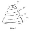
発熱体は螺旋形状を有してもよい。長軸方向軸は、螺旋形状の中心軸に沿って画定されてもよい。螺旋形状の発熱体によって画定される内部体積の断面積は、内部体積の第一の端から内部体積の第二の端へと減少しうる。保持材料の第一の中央領域は、内部体積の第一の端に向かって位置してもよい。保持材料の第二の中央領域は、内部体積の第二の端に向かって位置してもよい。したがって、動作中、第一の中央領域の温度は、第二の中央領域の温度よりも低い場合がある。これは、上述の利点を有しうる。 The heating element may have a helical shape. The longitudinal axis may be defined along the central axis of the helical shape. The cross-sectional area of the interior volume defined by the helically shaped heating element may decrease from a first end of the interior volume to a second end of the interior volume. The first central region of retention material may be located towards the first end of the interior volume. The second central region of retention material may be located towards the second end of the interior volume. Thus, during operation, the temperature of the first central region may be lower than the temperature of the second central region. This may have the advantages mentioned above.
好ましい実施形態では、発熱体の螺旋形状は、先端を切断した螺旋である。発熱体の曲率半径は、内部体積の断面積が減少するのと同じ方向に長軸方向軸に沿って減少してもよい。 In a preferred embodiment, the helical shape of the heating element is a truncated helix. The radius of curvature of the heating element may decrease along the longitudinal axis in the same direction as the cross-sectional area of the internal volume decreases.
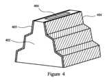
ヒーター組立品は、第一の発熱体および第二の発熱体を含んでもよい。保持材料の内部体積は、第一の発熱体と第二の発熱体との間に画定されてもよい。 The heater assembly may include a first heating element and a second heating element. An internal volume of the retaining material may be defined between the first heating element and the second heating element.
第一の発熱体と第二の発熱体との間の分離は、内部体積の断面積が減少するのと同じ方向に長軸方向軸に沿って減少してもよい。第一の発熱体および第二の発熱体のそれぞれは、一連の接続された表面を含んでもよい。表面は、次に、長軸方向軸に対して実質的に平行であり、長軸方向軸に対して実質的に直角を成してもよい。第一の発熱体および第二の発熱体は、第一の発熱体および第二の発熱体の実質的に平行な表面間の分離が長軸方向軸に沿って減少するように配設されてもよい。隣接した表面は、段を形成してもよい。言い換えれば、段は、長軸方向軸に実質的に平行な表面と、長軸方向軸に実質的に直角を成す表面とによって形成されうる。第一の発熱体および第二の発熱体はそれぞれ、第一の段および第二の段を含んでもよい。第一の段における発熱体間の分離は、第二の段における分離よりも大きくてもよい。保持材料の第一の中央部分は、第一の発熱体と第二の発熱体の第一の段の間に位置しうる。保持材料の第二の中央部分は、第一の発熱体と第二の発熱体の第二の段の間に位置しうる。第一の発熱体および第二の発熱体はさらなる段を含んでもよく、例えば、第一の発熱体および第二の発熱体は、第三の段を含んでもよい。 The separation between the first heating element and the second heating element may decrease along the longitudinal axis in the same direction as the cross-sectional area of the internal volume decreases. Each of the first heating element and the second heating element may include a series of connected surfaces. The surface, in turn, may be substantially parallel to the longitudinal axis and substantially perpendicular to the longitudinal axis. The first heating element and the second heating element are arranged such that the separation between the substantially parallel surfaces of the first heating element and the second heating element decreases along the longitudinal axis. Good too. Adjacent surfaces may form steps. In other words, a step may be formed by a surface substantially parallel to the longitudinal axis and a surface substantially perpendicular to the longitudinal axis. The first heating element and the second heating element may each include a first stage and a second stage. The separation between the heating elements in the first stage may be greater than the separation in the second stage. The first central portion of the retaining material may be located between the first stage of the first heating element and the second heating element. The second central portion of the retaining material may be located between the first heating element and the second stage of the second heating element. The first heating element and the second heating element may include further stages, for example the first heating element and the second heating element may include a third stage.
第一の中央領域から発熱体までの最小距離は、第二の中央領域から発熱体までの最小距離よりも大きくてもよい。 The minimum distance from the first central region to the heating element may be greater than the minimum distance from the second central region to the heating element.
第一の化合物の沸点は、160度~280度であってもよい。第一の化合物の沸点は、約247℃であってもよい。第一の化合物は、ニコチンであってもよい。 The boiling point of the first compound may be from 160 degrees to 280 degrees. The boiling point of the first compound may be about 247°C. The first compound may be nicotine.
第二の化合物の沸点は、210度~330度であってもよい。第二の化合物の沸点は、約290℃であってもよい。第二の化合物は、グリセロールであってもよい。 The second compound may have a boiling point of 210 degrees to 330 degrees. The second compound may have a boiling point of about 290°C. The second compound may be glycerol.
内部体積は、長軸方向軸に沿って第一の中央領域および第二の中央領域から間隙を介した第三の中央領域を含んでもよい。第三の中央部分は、第二の中央領域と比較して、第一の中央領域の反対側に位置してもよい。動作中、第三の中央領域は、第一の中央部分および第二の中央部分の温度よりも低い温度に達してもよい。第三の中央領域から発熱体までの最小距離は、第一の中央領域から発熱体までの最小距離よりも大きく、第二の中央領域から発熱体までの最小距離よりも大きくてもよい。異なる温度を有する内部体積の領域を提供することが、液体エアロゾル形成基体の様々な化合物の気化の制御をどのように改善するかは既に説明されており、これらの化合物は異なる沸点を有する。第一の領域よりもさらに低い温度を有する第三の中央領域を提供することによって、気化の制御は有利なことにさらに改善されうる。 The interior volume may include a third central region spaced from the first central region and the second central region along the longitudinal axis. The third central portion may be located on the opposite side of the first central region compared to the second central region. During operation, the third central region may reach a temperature that is lower than the temperature of the first central portion and the second central portion. The minimum distance from the third central region to the heating element may be greater than the minimum distance from the first central region to the heating element, and may be greater than the minimum distance from the second central region to the heating element. It has already been explained how providing regions of internal volume with different temperatures improves the control of vaporization of various compounds of the liquid aerosol-forming substrate, these compounds having different boiling points. By providing a third central region having an even lower temperature than the first region, control of vaporization may advantageously be further improved.
さらに、エアロゾル形成基体は、第三の化合物を含んでもよい。第三の化合物の沸点は、第一の化合物の沸点よりも低くてもよい。第三の化合物の沸点は、第二の化合物の沸点よりも低くてもよい。第三の化合物の沸点は、100~240℃、好ましくは120~220℃でありうる。第三の化合物の沸点は、188℃であることが好ましい。第三の化合物は、プロピレングリコールであってもよい。第三の中央領域の低い温度では、有利なことに、第三の化合物が主に気化されうる。こうした第三の中央領域を提供することによって、第一の化合物、第二の化合物、および第三の化合物のそれぞれの同時の気化が確実となりうる。 Additionally, the aerosol-forming substrate may include a third compound. The boiling point of the third compound may be lower than the boiling point of the first compound. The boiling point of the third compound may be lower than the boiling point of the second compound. The boiling point of the third compound may be 100-240°C, preferably 120-220°C. The boiling point of the third compound is preferably 188°C. The third compound may be propylene glycol. At the lower temperature of the third central region, advantageously, the third compound can be predominantly vaporized. By providing such a third central region, simultaneous vaporization of each of the first compound, the second compound, and the third compound may be ensured.
少なくとも一つの気流経路は、長軸方向軸に沿って第一の中央領域および第二の中央領域から間隙を介した、内部体積の第三の中央領域を通過してもよい。エアロゾル形成基体が第三の化合物を含むとき、これは、三つの化合物すべてのベイパーが、ユーザーによって吸入されるために少なくとも一つの気流経路に入ることを確実にしうる。 At least one airflow path may pass through a third central region of the interior volume spaced from the first central region and the second central region along the longitudinal axis. When the aerosol-forming substrate includes a third compound, this may ensure that vapor of all three compounds enters at least one airflow path for inhalation by the user.
ヒーター組立品は、抵抗加熱配設を使用してもよい。少なくとも一つの発熱体は抵抗発熱体であってもよい。ヒーター組立品、特に発熱体は、電流の供給源に電気的に接続されるか、または接続可能であるように構成されてもよい。発熱体は、適切な電気特性および機械特性を有する任意の材料を含むか、またはそれから形成されてもよい。好適な材料としては、ドープされたセラミックなどの半導体、「導電性」のセラミック(例えば、二ケイ化モリブデンなど)、炭素、黒鉛、金属、合金、およびセラミック材料と金属材料とで作製された複合材料が挙げられるが、これらに限定されない。こうした複合材料は、ドープされたセラミックまたはドープされていないセラミックを含んでもよい。適切なドープされたセラミックの例としては、ドープ炭化ケイ素が挙げられる。適切な金属の例としては、チタン、ジルコニウム、タンタル、および白金族の金属が含まれる。適切な合金の例には、ステンレス鋼、コンスタンタン、ニッケル含有、コバルト含有、クロム含有、アルミニウム含有、チタン含有、ジルコニウム含有、ハフニウム含有、ニオビウム含有、モリブデン含有、タンタル含有、タングステン含有、スズ含有、ガリウム含有、マンガン含有、および鉄含有の合金、およびニッケル、鉄、コバルト、ステンレス鋼系の超合金、Timetal(登録商標)、鉄-アルミニウム系合金および鉄-マンガン-アルミニウム系合金が含まれる。Timetal(登録商標)は、Titanium Metals Corporationの登録商標である。ワイヤーは、一つ以上の電気絶縁体で被覆されてもよい。好ましい材料は、304、316、304L、316Lステンレス鋼、および黒鉛であってもよい。 The heater assembly may use a resistive heating arrangement. The at least one heating element may be a resistive heating element. The heater assembly, particularly the heating element, may be electrically connected or configured to be connectable to a source of electrical current. The heating element may include or be formed from any material with suitable electrical and mechanical properties. Suitable materials include semiconductors such as doped ceramics, "conductive" ceramics (such as molybdenum disilicide), carbon, graphite, metals, alloys, and composites made of ceramic and metallic materials. Materials include, but are not limited to: Such composite materials may include doped or undoped ceramics. An example of a suitable doped ceramic is doped silicon carbide. Examples of suitable metals include titanium, zirconium, tantalum, and platinum group metals. Examples of suitable alloys include stainless steel, constantan, nickel-containing, cobalt-containing, chromium-containing, aluminum-containing, titanium-containing, zirconium-containing, hafnium-containing, niobium-containing, molybdenum-containing, tantalum-containing, tungsten-containing, tin-containing, gallium-containing nickel, iron, cobalt, stainless steel based superalloys, Timetal®, iron-aluminum based alloys and iron-manganese-aluminum based alloys. Timetal® is a registered trademark of Titanium Metals Corporation. The wire may be coated with one or more electrical insulators. Preferred materials may be 304, 316, 304L, 316L stainless steel, and graphite.
加えて、上記材料の組み合わせを使用してもよい。例えば、高い比抵抗を有する材料を、低い比抵抗を有する材料と組み合わせてもよい。これは、材料のうちの一つが他の観点、例えば価格、機械加工性、またはその他の物理的および化学的パラメータの観点から、より有益である場合に、有利である場合がある。 Additionally, combinations of the above materials may be used. For example, a material with high resistivity may be combined with a material with low resistivity. This may be advantageous if one of the materials is more beneficial from other points of view, such as from the point of view of price, machinability, or other physical and chemical parameters.
少なくとも一つの発熱体の抵抗は、内部体積の断面積が減少するのと同じ方向に長軸方向軸に沿って増加してもよい。動作中、これは有利なことに、発熱体の長さに沿った温度勾配を提供しうる。発熱体の温度は、内部体積の断面積が減少するのと同じ方向に長軸方向軸に沿って増加してもよい。上述のように、保持材料の第一の中央領域および第二の中央領域は、発熱体によって画定される内部体積の幾何学的形状の結果として、一般的に異なる温度に加熱される。発熱体に沿った温度勾配は、保持材料の第一の中央領域と第二の中央領域との間の温度差を増加させうる。したがって、こうした温度勾配を有する発熱体を提供することは、第一の化合物および第二の化合物の気化の制御の増大を可能にしうる。 The resistance of the at least one heating element may increase along the longitudinal axis in the same direction as the cross-sectional area of the internal volume decreases. During operation, this may advantageously provide a temperature gradient along the length of the heating element. The temperature of the heating element may increase along the longitudinal axis in the same direction as the cross-sectional area of the internal volume decreases. As mentioned above, the first central region and the second central region of the retaining material are generally heated to different temperatures as a result of the geometry of the internal volume defined by the heating element. A temperature gradient along the heating element can increase the temperature difference between the first central region and the second central region of the retaining material. Therefore, providing a heating element with such a temperature gradient may allow for increased control of the vaporization of the first compound and the second compound.
発熱体の抵抗は、発熱体の断面積の減少の結果として増加しうる。発熱体の断面、または断面積を変化させることは、結果として発熱体の異なるセクションが異なる温度に達することとなりうる。例えば、抵抗発熱体では、より小さな断面積を有する発熱体のセクションはより大きな抵抗を有する場合があり、したがって、より高い温度に抵抗加熱されうる。 The resistance of the heating element may increase as a result of the reduction in the cross-sectional area of the heating element. Varying the cross-section, or cross-sectional area, of the heating element can result in different sections of the heating element reaching different temperatures. For example, in a resistive heating element, sections of the heating element that have a smaller cross-sectional area may have a greater resistance and therefore can be resistively heated to a higher temperature.
別の方法として、または追加的に、これは、液体エアロゾル形成基体の貯蔵構成要素に、より大きな速度で温度が上昇する領域、およびより低い速度で温度が上昇する領域を提供しうる。上述のように、これは、より高い沸点およびより低い沸点を有する液体エアロゾル形成基体化合物が所望の速度で同時に気化することにつながりうる。 Alternatively or additionally, this may provide the storage component of the liquid aerosol-forming substrate with regions of increasing temperature at a greater rate and regions of increasing temperature at a lower rate. As mentioned above, this can lead to liquid aerosol-forming substrate compounds with higher and lower boiling points vaporizing simultaneously at the desired rate.
発熱体は、第一の端と第二の端との間に延びてもよい。例えば、発熱体の長さは、第一の端と第二の端との間に延びてもよい。発熱体は、第一の端と第二の端との間の第一の点に第一の断面積を有してもよい。発熱体は、第一の点と第二の端との間の第二の点に第一の断面積を有してもよい。例えば、第一の断面積は、第二の断面積よりも少なくとも10、20、30、40、50、60、70、または80パーセント未満であってもよい。 A heating element may extend between the first end and the second end. For example, the length of the heating element may extend between the first end and the second end. The heating element may have a first cross-sectional area at a first point between the first end and the second end. The heating element may have a first cross-sectional area at a second point between the first point and the second end. For example, the first cross-sectional area may be at least 10, 20, 30, 40, 50, 60, 70, or 80 percent less than the second cross-sectional area.
発熱体の長さに沿った最小断面積は、発熱体の長さに沿った最大断面積よりも少なくとも10パーセント未満であってもよい。発熱体の長さに沿った最小断面積は、発熱体の長さに沿った最大断面積よりも少なくとも20、40、60、または80パーセント未満であってもよい。 The minimum cross-sectional area along the length of the heating element may be at least 10 percent less than the maximum cross-sectional area along the length of the heating element. The minimum cross-sectional area along the length of the heating element may be at least 20, 40, 60, or 80 percent less than the maximum cross-sectional area along the length of the heating element.
発熱体の幅または厚さまたは幅および厚さの両方は、発熱体の長さに沿って変化してもよい。 The width or thickness or both width and thickness of the heating element may vary along the length of the heating element.
ヒーター組立品は誘導加熱配設を使用してもよい。抵抗ヒーターに関連付けられた電力損失、特に抵抗ヒーターと電力送達システムとの間の接続部における接触抵抗に起因する損失を理由に、抵抗配設ではなく誘導加熱の使用はエネルギー変換の改善を提供する。機能するために、抵抗ヒーターは恒久的または交換可能のいずれかで装置またはヒーター組立品内に提供されるリードを通して電源に接続される。改善した自動製造技法を用いてさえ、抵抗ヒーターシステムは、寄生損失を生成するリードにおいて一般に接触抵抗を有する。交換可能な抵抗ヒーター装置はまた、交換可能なカートリッジとリードとの間の接触抵抗を増加させるフィルムまたはその他の材料の堆積に悩まされうる。対照的に、誘導加熱システムは、発熱体とリードとの間の接触を必要とせず、したがって抵抗ヒーター装置に存在する接触抵抗の問題に悩まされることはない。 The heater assembly may use an induction heating arrangement. Because of the power losses associated with resistive heaters, particularly losses due to contact resistance at the connections between the resistive heater and the power delivery system, the use of induction heating rather than resistive arrangements provides improved energy conversion. . To function, resistive heaters are connected to a power source through leads provided within the device or heater assembly, either permanently or replaceably. Even with improved automated manufacturing techniques, resistive heater systems commonly have contact resistance in the leads that creates parasitic losses. Replaceable resistive heater devices can also suffer from build-up of films or other materials that increase contact resistance between the replaceable cartridge and the leads. In contrast, induction heating systems do not require contact between the heating element and the leads and therefore do not suffer from the contact resistance problems present in resistive heater devices.
少なくとも一つの発熱体はサセプタであってもよい。サセプタとしての発熱体は、交番磁界によって加熱可能であるように構成されてもよい。交番磁界は、エアロゾル発生システムによって発生されてもよい。交番磁界は、エアロゾル発生システムのインダクタコイルを通して交流電流を流すことによって発生されてもよく、インダクタコイルは使用時にヒーター組立品を囲んでいる。交流電流は、任意の好適な周波数を有しうる。交流電流は、高周波の交流電流としうる。交流電流は、100キロヘルツ(kHz)~30メガヘルツ(MHz)の周波数を有してもよい。 The at least one heating element may be a susceptor. The heating element as a susceptor may be configured to be heated by an alternating magnetic field. The alternating magnetic field may be generated by an aerosol generation system. The alternating magnetic field may be generated by passing an alternating current through an inductor coil of the aerosol generation system, which surrounds the heater assembly in use. The alternating current may have any suitable frequency. The alternating current may be a high frequency alternating current. The alternating current may have a frequency of 100 kilohertz (kHz) to 30 megahertz (MHz).
発熱体によって発生される熱は、保持材料に伝達されてもよい。こうした場合、誘導加熱配設は、ヒーター組立品の発熱体と、例えば、エアロゾル発生システムの電源への別の構成要素との間に電気接点を形成する必要がないという利点を有しうる。さらに、ヒーター組立品は、より安価に製造されうる。例えば、ヒーター組立品は、カートリッジの一部として製造されてもよい。カートリッジは作動に用いる装置よりもずっと大量に製造される一般に使い捨ての物品である。従って、より高価な装置を必要とする場合でも、カートリッジのコストが低減されることで、製造者および消費者の両者にとって著しいコスト節約につながりうる。 Heat generated by the heating element may be transferred to the retaining material. In such cases, the induction heating arrangement may have the advantage of not requiring electrical contact to be made between the heating element of the heater assembly and another component, for example, to the power supply of the aerosol generation system. Additionally, the heater assembly can be manufactured less expensively. For example, the heater assembly may be manufactured as part of a cartridge. Cartridges are generally disposable items that are manufactured in much larger quantities than the devices used to operate them. Thus, even if more expensive equipment is required, the reduced cost of the cartridge can result in significant cost savings for both manufacturers and consumers.
別の方法として、保持材料は、サセプタ素子を含んでもよい。保持材料は、サセプタ素子から成ってもよい。少なくとも一つの発熱体は、保持材料のサセプタ素子を加熱するように構成されたインダクタコイルを形成してもよく、またはこれを含んでもよい。少なくとも一つの発熱体は、電源に電気的に接続されてもよく、または接続可能であってもよい。電源は、交流電流を発生するように構成されてもよい。発熱体は、交番磁界を発生するように構成されてもよい。第一の中央領域および第二の中央領域の温度は、交番磁界の磁束密度または磁界強度に依存しうる。交番磁界の密度または強度は、インダクタコイルを含むか、またはインダクタコイルを形成する発熱体によって画定される内部体積の断面積が減少するにつれて増大しうる。交番磁界の磁束密度または磁界強度は、発熱体が保持材料のそれぞれの中央領域に近いほど増加しうる。こうした配設は、ヒーター組立品が熱平衡または最大温度に達した時であっても内部体積中に大きな温度勾配が維持される、という利点を有しうる。 Alternatively, the holding material may include a susceptor element. The holding material may consist of a susceptor element. The at least one heating element may form or include an inductor coil configured to heat the susceptor element of the holding material. The at least one heating element may be electrically connected or connectable to a power source. The power source may be configured to generate alternating current. The heating element may be configured to generate an alternating magnetic field. The temperature of the first central region and the second central region may depend on the magnetic flux density or field strength of the alternating magnetic field. The density or strength of the alternating magnetic field may increase as the cross-sectional area of the internal volume defined by the heating element containing or forming the inductor coil decreases. The magnetic flux density or field strength of the alternating magnetic field may increase the closer the heating elements are to the respective central region of the holding material. Such an arrangement may have the advantage that a large temperature gradient is maintained in the internal volume even when the heater assembly reaches thermal equilibrium or maximum temperature.
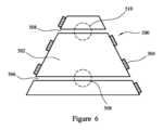
ヒーター組立品は、第一の発熱体および第二の発熱体を備えてもよく、第一の発熱体および第二の発熱体のそれぞれは、インダクタコイルを含むか、または形成する。例えば、第一の発熱体および第二の発熱体は、上述のように段付けされてもよい。保持材料の内部体積は、第一の発熱体と第二の発熱体との間に画定されてもよい。第一の発熱体は、第二の発熱体と反対側に位置付けられてもよい。第一の発熱体および第二の発熱体のそれぞれは、平坦なインダクタコイルを含んでもよい。インダクタコイルを含む二つの発熱体を提供することは、有利なことに、磁界強度または磁束密度を増加させうる。インダクタコイルは、内部体積内で互いに追加する磁界を提供するように配設されてもよい。同様に、第一の発熱体および第二の発熱体を通過する交流電流は、内部体積内で互いに追加する磁界を提供するように構成されてもよい。同じ周波数の交流電流が、第一の発熱体および第二の発熱体のそれぞれを通過してもよい。交流電流は、同じ電源によって供給されてもよい。 The heater assembly may include a first heating element and a second heating element, each of the first heating element and second heating element including or forming an inductor coil. For example, the first heating element and the second heating element may be stepped as described above. An internal volume of the retaining material may be defined between the first heating element and the second heating element. The first heating element may be positioned opposite the second heating element. Each of the first heating element and the second heating element may include a flat inductor coil. Providing two heating elements including inductor coils may advantageously increase the magnetic field strength or flux density. The inductor coils may be arranged to provide mutually additive magnetic fields within the interior volume. Similarly, alternating current passing through the first heating element and the second heating element may be configured to provide mutually additive magnetic fields within the interior volume. An alternating current of the same frequency may pass through each of the first heating element and the second heating element. The alternating current may be supplied by the same power source.
少なくとも一つの気流経路は、保持材料を通して画定され、かつ長軸方向軸に平行な方向に第一の中央領域および第二の中央領域を通過する気流経路を含んでもよい。気流経路は、使用時、空気が最大の断面積を有する端から保持材料に入るように配設されてもよい。言い換えれば、空気は、第一の中央領域または第二の中央領域のうちのより低温の方をまず通過しうる。ヒーター組立品が動作しているとき、入ってくる空気は保持材料よりもかなり低温でありうる。したがって、保持材料に入る空気は、有利なことに、それぞれの中央領域を冷却しうる。空気が第一の中央領域または第二の中央領域のうち別の方に到達したとき、空気はヒーター組立品によって加熱されている場合があり、そのため空気の冷却効果は減少している場合がある。したがって、気流経路のこうした配設は、有利なことに、第一の中央領域と第二の中央領域との間の温度差を増大させうる。 The at least one airflow path may be defined through the retention material and include an airflow path passing through the first central region and the second central region in a direction parallel to the longitudinal axis. The airflow path may be arranged such that, in use, air enters the retaining material from the end with the largest cross-sectional area. In other words, the air may first pass through the cooler of the first central region or the second central region. When the heater assembly is operating, the incoming air may be significantly cooler than the holding material. Air entering the holding material may thus advantageously cool the respective central region. When the air reaches the other of the first central region or the second central region, the air may have been heated by the heater assembly, and thus the cooling effectiveness of the air may be reduced. . Accordingly, such an arrangement of airflow paths may advantageously increase the temperature difference between the first central region and the second central region.
別の方法として、少なくとも一つの気流経路は、長軸方向軸に直角を成す方向に第一の中央領域を通過する保持材料を通して画定された第一の気流経路を含んでもよい。少なくとも一つの気流経路は、長軸方向軸に直角を成す方向に第二の中央領域を通過する保持材料を通して画定された第二の気流経路を含んでもよい。 Alternatively, the at least one airflow path may include a first airflow path defined through the retention material passing through the first central region in a direction perpendicular to the longitudinal axis. The at least one airflow path may include a second airflow path defined through the retention material passing through the second central region in a direction perpendicular to the longitudinal axis.
ヒーター組立品は、エアロゾル形成基体を保存するための貯蔵部を備えてもよい。ヒーター組立品は、エアロゾル形成基体の貯蔵部を備えてもよい。貯蔵部は、エアロゾル形成基体を保持材料に供給するように構成されてもよい。貯蔵部は、保持材料によって充填された内部体積が最大の断面積を有する場所の保持材料にエアロゾル形成基体を供給するように構成されてもよい。使用時、これは、貯蔵部のエアロゾル形成基体は保持材料中のエアロゾル形成基体よりも低温でありうるため、内部体積の第一の中央領域と第二の中央領域との間の温度差を有利なことに増大させうる。 The heater assembly may include a reservoir for storing the aerosol-forming substrate. The heater assembly may include a reservoir of aerosol-forming substrate. The reservoir may be configured to supply the aerosol-forming substrate to the retention material. The reservoir may be configured to supply the aerosol-forming substrate to the retention material at a location where the internal volume filled by the retention material has a maximum cross-sectional area. In use, this favors the temperature difference between the first central region and the second central region of the internal volume, since the aerosol-forming substrate in the reservoir may be cooler than the aerosol-forming substrate in the holding material. In fact, it can be increased.
保持材料は、エアロゾル形成基体を保存してもよく、または保存するように構成されてもよい。保持材料は、貯蔵部と流体連通していてもよい。 The retention material may preserve or be configured to preserve the aerosol-forming substrate. The retention material may be in fluid communication with the reservoir.
貯蔵部は、エアロゾル形成基体を含有する貯蔵部ハウジングを備えてもよい。チャネルは、ハウジングを通して画定されてもよい。少なくとも一つの気流チャネルは、このチャネルを通過してもよい。 The reservoir may include a reservoir housing containing an aerosol-forming substrate. A channel may be defined through the housing. At least one airflow channel may pass through this channel.
本開示によると、上述のヒーター組立品を備えるエアロゾル発生システムも提供される。エアロゾル発生システムは、ヒーター組立品に接続可能な電源をさらに備えてもよい。エアロゾル発生システムは、電源からヒーター組立品に供給される電力を制御するためのコントローラをさらに備えてもよい。よって、コントローラは、発熱体の加熱を制御しうる。 According to the present disclosure, an aerosol generation system comprising the heater assembly described above is also provided. The aerosol generation system may further include a power source connectable to the heater assembly. The aerosol generation system may further include a controller for controlling power provided to the heater assembly from the power source. Thus, the controller can control the heating of the heating element.
電源は電池であってもよい。電源は、発熱体に電力を供給するように構成されてもよい。これは発熱体を加熱するためでありうる。 The power source may be a battery. The power source may be configured to power the heating element. This may be to heat the heating element.
電源は、発熱体を抵抗加熱するために、発熱体に電力を供給するように構成されてもよい。エアロゾル発生システムは、インダクタコイルを備えてもよい。 The power source may be configured to provide power to the heating element to resistively heat the heating element. The aerosol generation system may include an inductor coil.
エアロゾル発生システムの電源は、ヒーター組立品の少なくとも一つの発熱体がインダクタコイルを形成するか、または含むときに、交流電流をインダクタコイルに提供するように構成されてもよい。エアロゾル発生システムの電源は、ヒーター組立品の少なくとも一つの発熱体がインダクタコイルを形成するか、または含むときに、振動電流をインダクタコイルに提供するように構成されてもよい。振動電流は、高周波振動電流であってもよい。本明細書で使用される高周波振動電流は、100kHz~10MHzの周波数を有する振動電流を意味する。 The power source of the aerosol generation system may be configured to provide alternating current to the inductor coil when at least one heating element of the heater assembly forms or includes an inductor coil. The power source of the aerosol generation system may be configured to provide an oscillating current to the inductor coil when at least one heating element of the heater assembly forms or includes an inductor coil. The oscillating current may be a high frequency oscillating current. High frequency oscillating current as used herein refers to oscillating current having a frequency of 100 kHz to 10 MHz.
エアロゾル発生システムは、カートリッジを備えてもよく、カートリッジは、ヒーター組立品を含むカートリッジハウジングを備える。カートリッジは、エアロゾル発生装置と係合するように構成されてもよい。電源は、カートリッジがエアロゾル発生装置と係合したときのみ、電力を発熱体に供給するように構成されてもよい。 The aerosol generation system may include a cartridge that includes a cartridge housing that includes a heater assembly. The cartridge may be configured to engage an aerosol generating device. The power source may be configured to provide power to the heating element only when the cartridge is engaged with the aerosol generating device.
カートリッジは、空気吸込み口を備えてもよい。カートリッジは、空気出口を備えてもよい。空気吸込み口は、空気出口と流体連通してもよい。発熱体は、空気吸込み口の下流に配置されてもよい。発熱体は、空気出口の上流に配置されてもよい。 The cartridge may include an air intake. The cartridge may be equipped with an air outlet. The air inlet may be in fluid communication with the air outlet. The heating element may be placed downstream of the air inlet. A heating element may be placed upstream of the air outlet.
カートリッジは、発熱体に電気的に接続された第一の電気接点および第二の電気接点を備えてもよい。電気接点は、スズ、銀、金、銅、アルミニウム、ステンレス鋼などの鋼、リン青銅、アンチモンで合金化されたスズ、ジルコニウムで合金化されたスズ、ビスマスで合金化されたスズ、または有機酸に対する耐性を向上させる他の構成成分で合金化されたスズのうちの一つ以上を含みうる。 The cartridge may include a first electrical contact and a second electrical contact electrically connected to the heating element. Electrical contacts can be made of tin, silver, gold, copper, aluminum, steel such as stainless steel, phosphor bronze, tin alloyed with antimony, tin alloyed with zirconium, tin alloyed with bismuth, or organic acids. may include one or more of the tin alloyed with other components to improve resistance to.
電気接点は、カートリッジがエアロゾル発生装置と係合したときに、エアロゾル発生装置上の対応する電気接点と電気的接続を形成するように構成されてもよい。 The electrical contacts may be configured to form electrical connections with corresponding electrical contacts on the aerosol generator when the cartridge is engaged with the aerosol generator.
ヒーター組立品に関連して随意に説明される貯蔵部は、代わりにカートリッジの一部を形成してもよい。ヒーター組立品、および特に、ヒーター組立品の保持材料は、貯蔵部と流体連通していてもよい。 A reservoir optionally described in connection with a heater assembly may alternatively form part of a cartridge. The heater assembly, and particularly the retaining material of the heater assembly, may be in fluid communication with the reservoir.
エアロゾル発生システムは、エアロゾル発生装置をさらに備えてもよい。カートリッジは、エアロゾル発生装置に取り外し可能に受容可能であってもよい。 The aerosol generation system may further include an aerosol generation device. The cartridge may be removably receivable in the aerosol generating device.
エアロゾル発生装置は、電源およびコントローラを含む装置ハウジングを備えてもよい。 The aerosol generating device may include a device housing that includes a power source and a controller.
エアロゾル発生システムは、少なくとも一つの気流経路と流体連通するマウスピースをさらに含み、ユーザーが少なくとも一つの気流経路を通して空気を引き出すことを可能にしてもよい。カートリッジはマウスピースを備えてもよい。使用時、カートリッジがエアロゾル発生装置と係合すると、ユーザーは、カートリッジのマウスピースで吸煙しうる。これにより、空気は、空気吸込み口を通って流れ、次いで、ヒーター組立品または発熱体を横切って、それにわたって、それを通過して、またはそれを通った後、空気出口を通って流れうる。 The aerosol generation system may further include a mouthpiece in fluid communication with the at least one airflow path to allow a user to draw air through the at least one airflow path. The cartridge may include a mouthpiece. In use, when the cartridge is engaged with the aerosol generating device, a user may inhale with the mouthpiece of the cartridge. This allows air to flow through the air inlet and then across, over, through, or through the heater assembly or heating element and then through the air outlet.
エアロゾル発生システムは、手持ち式エアロゾル発生システムであってもよい。エアロゾル発生システムは、電気加熱式の喫煙システムとしうる。 The aerosol generation system may be a handheld aerosol generation system. The aerosol generation system may be an electrically heated smoking system.
本開示によると、上述のエアロゾル発生システムで使用するためのカートリッジも提供され、カートリッジは上述のヒーター組立品を含む。 According to the present disclosure, there is also provided a cartridge for use in the aerosol generation system described above, the cartridge including the heater assembly described above.
本開示によれば、エアロゾル発生システムを使用する方法も提供され、エアロゾル発生システムは、凝縮形態のエアロゾル形成基体を含有する保持材料であって、エアロゾル形成基体が第一の化合物および第二の化合物を含み、第二の化合物は第一の化合物よりも高い沸点を有する、保持材料と、保持材料を通して画定された少なくとも一つの気流経路と、内部体積を画定するように形作られた少なくとも一つの発熱体を含むヒーター組立品であって、内部体積が保持材料で充填されている、ヒーター組立品と、電源と、電源からヒーター組立品に供給される電力を制御するためのコントローラと、を備え、内部体積が長軸方向軸に沿って減少する断面積を有し、少なくとも一つの空気流通路が、内部体積の第一の中央領域および内部体積の第二の中央領域を通過し、第一の中央領域および第二の中央領域が、長軸方向軸に沿って間隙を介していて、方法が、第一の中央領域が第二の中央領域とは異なる温度に加熱されるように、少なくとも一つの発熱体を起動して保持材料を加熱することを含む。 According to the present disclosure, there is also provided a method of using an aerosol generation system, the aerosol generation system comprising a carrier material containing an aerosol-forming substrate in condensed form, the aerosol-forming substrate containing a first compound and a second compound. a retaining material, the second compound having a higher boiling point than the first compound; at least one air flow path defined through the retaining material; and at least one exothermic body shaped to define an interior volume. a heater assembly comprising: a heater assembly, the interior volume of which is filled with a retaining material; a power supply; and a controller for controlling power supplied to the heater assembly from the power supply; the interior volume has a cross-sectional area that decreases along the longitudinal axis, at least one air flow passage passing through the first central region of the interior volume and the second central region of the interior volume; the central region and the second central region are spaced apart along the longitudinal axis, and the method includes at least one step such that the first central region is heated to a different temperature than the second central region. activating two heating elements to heat the holding material.
少なくとも一つの発熱体を起動する工程は、第一の中央領域を、第二の中央領域の温度よりも低い温度に加熱することを含みうる。 Activating the at least one heating element may include heating the first central region to a temperature that is lower than the temperature of the second central region.
少なくとも一つの発熱体を起動する工程は、第一の中央領域を、第二の中央領域の温度よりも少なくとも20℃低い温度に加熱することを含みうる。 Activating the at least one heating element may include heating the first central region to a temperature that is at least 20° C. lower than the temperature of the second central region.
少なくとも一つの発熱体を起動する工程は、内部体積の第一の中央領域を160~280℃の温度に加熱することを含みうる。 Activating the at least one heating element may include heating the first central region of the interior volume to a temperature of 160-280°C.
少なくとも一つの発熱体を起動する工程は、内部体積の第二の中央領域を210~330℃の温度に加熱することを含みうる。 Activating the at least one heating element may include heating the second central region of the interior volume to a temperature of 210-330°C.
少なくとも一つの発熱体を起動する工程は、少なくとも一つの気流経路に入るベイパーが発生するように、エアロゾル形成基体を加熱することを含みうる。 Activating the at least one heating element may include heating the aerosol-forming substrate to generate vapor that enters the at least one airflow path.
内部体積の第一の中央領域を通過する少なくとも一つの気流経路の部分に入るベイパーは、第二の化合物よりも高い重量で第一の化合物を含む。 The vapor entering the portion of the at least one airflow path passing through the first central region of the interior volume contains a higher weight of the first compound than the second compound.
内部体積の第二の中央領域を通過する少なくとも一つの気流経路の部分に入るベイパーは、第一の化合物よりも高い重量で第二の化合物を含む。 The vapor entering the portion of the at least one airflow path passing through the second central region of the interior volume contains a higher weight of the second compound than the first compound.
本明細書で使用される「エアロゾル」という用語は、気体中の固体微粒子、または液滴、または固体微粒子と液滴の組み合わせの分散を指す。エアロゾルは、可視であってもよく、または不可視であってもよい。エアロゾルは、室温において通常は液体または固体である物質の蒸気だけでなく、固体粒子もしくは液体の液滴、または固体粒子および液体の液滴の組み合わせも含んでもよい。 The term "aerosol" as used herein refers to a dispersion of solid particulates, or liquid droplets, or a combination of solid particulates and liquid droplets in a gas. Aerosols may be visible or invisible. Aerosols may contain not only vapors of substances that are normally liquid or solid at room temperature, but also solid particles or liquid droplets, or a combination of solid particles and liquid droplets.
本明細書で使用される「エアロゾル形成基体」という用語は、エアロゾルを形成することができる揮発性化合物を放出する能力を有する基体を指す。揮発性化合物はエアロゾル形成基体を加熱する、または燃焼することによって放出されてもよい。 As used herein, the term "aerosol-forming substrate" refers to a substrate that has the ability to emit volatile compounds that can form an aerosol. Volatile compounds may be released by heating or burning the aerosol-forming substrate.
エアロゾル形成基体は、複数の化合物を含んでもよい。複数の化合物は、異なる沸点を有してもよい。例えば、エアロゾル形成基体は、大気圧で第一の沸点を有する第一の化合物、および大気圧で第二の沸点を有する第二の化合物を含んでもよく、第一の沸点は第二の沸点よりも高い。エアロゾル形成基体は、大気圧で第三の沸点を有する第三の化合物を含んでもよい。 The aerosol-forming substrate may include multiple compounds. Multiple compounds may have different boiling points. For example, an aerosol-forming substrate may include a first compound having a first boiling point at atmospheric pressure and a second compound having a second boiling point at atmospheric pressure, the first boiling point being lower than the second boiling point. It's also expensive. The aerosol-forming substrate may include a third compound having a third boiling point at atmospheric pressure.
エアロゾル形成基体はエアロゾル形成体を含んでもよい。本明細書で使用される「エアロゾル形成体」は、使用時に、例えば、システムの動作温度にて熱分解に対して実質的に抵抗性である安定したエアロゾルの形成を容易にする、任意の適切な化合物または化合物の混合物を指す。適切なエアロゾル形成体は当業界で周知であり、これには多価アルコール(トリエチレングリコール、1,3-ブタンジオール、グリセリンなど)、多価アルコールのエステル(グリセロールモノアセテート、ジアセテート、またはトリアセテートなど)、およびモノカルボン酸、ジカルボン酸、またはポリカルボン酸の脂肪族エステル(ドデカン二酸ジメチル、テトラデカン二酸ジメチルなど)が挙げられるが、これらに限定されない。 The aerosol-forming substrate may include an aerosol former. As used herein, "aerosol former" refers to any suitable aerosol that, in use, facilitates the formation of a stable aerosol that is substantially resistant to thermal decomposition at, for example, the operating temperature of the system. refers to a compound or a mixture of compounds. Suitable aerosol formers are well known in the art and include polyhydric alcohols (such as triethylene glycol, 1,3-butanediol, glycerin, etc.), esters of polyhydric alcohols (glycerol monoacetate, diacetate, or triacetate). ), and aliphatic esters of monocarboxylic, dicarboxylic, or polycarboxylic acids (such as dimethyl dodecanedioate, dimethyl tetradecanedioate, etc.).
エアロゾル形成基体は、ニコチンを含んでもよい。エアロゾル形成基体は、水を含んでもよい。エアロゾル形成基体は、グリセリンとも呼ばれ、ニコチンよりも高い沸点を有するグリセロールを含んでもよい。エアロゾル形成基体は、プロピレングリコールを含んでもよい。エアロゾル形成基体は、植物由来材料を含んでもよい。エアロゾル形成基体は、均質化した植物由来材料を含んでもよい。エアロゾル形成基体は、たばこを含んでもよい。エアロゾル形成基体は、たばこ含有材料を含んでもよい。たばこ含有材料は、揮発性たばこ風味化合物を含有してもよい。これらの化合物は、加熱に伴いエアロゾル形成基体から放出され得る。エアロゾル形成基体は、均質化したたばこ材料を含んでもよい。エアロゾル形成基体は、その他の添加物および、風味剤などの成分を含んでもよい。 The aerosol-forming substrate may include nicotine. The aerosol-forming substrate may include water. The aerosol-forming substrate may include glycerol, also called glycerin, which has a higher boiling point than nicotine. The aerosol-forming substrate may include propylene glycol. The aerosol-forming substrate may include plant-derived materials. The aerosol-forming substrate may include homogenized plant-derived material. The aerosol-forming substrate may include tobacco. The aerosol-forming substrate may include a tobacco-containing material. The tobacco-containing material may contain volatile tobacco flavor compounds. These compounds can be released from the aerosol-forming substrate upon heating. The aerosol-forming substrate may include homogenized tobacco material. The aerosol-forming substrate may also include other additives and ingredients such as flavoring agents.
本明細書で使用される「液体エアロゾル形成基体」という用語は、凝縮形態のエアロゾル形成基体を指す。よって、「液体エアロゾル形成基体」は、液体、ゲル、またはペーストのうちの一つ以上であってもよく、またはこれらのうちの一つ以上を含んでもよい。液体エアロゾル形成基体がゲルもしくはペーストであるか、またはゲルもしくはペーストを含む場合、ゲルもしくはペーストは加熱時に液体化してもよい。例えば、ゲルまたはペーストは、50、75、100、150、または200℃未満の温度に加熱すると、液体化しうる。 The term "liquid aerosol-forming substrate" as used herein refers to an aerosol-forming substrate in condensed form. Thus, a "liquid aerosol-forming substrate" may be or include one or more of a liquid, a gel, or a paste. If the liquid aerosol-forming substrate is or includes a gel or paste, the gel or paste may liquefy upon heating. For example, a gel or paste may liquefy when heated to a temperature below 50, 75, 100, 150, or 200°C.
本明細書で使用される「発熱体」という用語は、電力が供給されるとそれ自体が温度上昇するように構成された素子と、サセプタ素子に結合されたインダクタコイルなど、電力が供給されると結合された構成要素の温度上昇を生じさせるように構成された素子の両方を包含する。 As used herein, the term "heating element" refers to an element configured to increase its temperature when energized, such as an inductor coil coupled to a susceptor element, when energized. and an element configured to cause an increase in temperature of a component coupled thereto.
本明細書で使用される「サセプタ素子」は、変動磁界に供された時に加熱する導電性素子を意味する。これはサセプタ素子に誘起された渦電流および/またはヒステリシス損失の結果でありうる。サセプタ素子のための可能性がある材料としては、黒鉛、モリブデン、炭化ケイ素、ステンレス鋼、ニオブ、アルミニウム、および事実上あらゆる他の導電性元素が挙げられる。有利なことに、サセプタ素子はフェライト素子である。サセプタ素子のための材料および幾何学的形状は、所望の電気抵抗および発熱を提供するように選ぶことができる。 As used herein, "susceptor element" refers to an electrically conductive element that heats up when subjected to a varying magnetic field. This may be the result of eddy currents and/or hysteresis losses induced in the susceptor element. Possible materials for the susceptor element include graphite, molybdenum, silicon carbide, stainless steel, niobium, aluminum, and virtually any other conductive element. Advantageously, the susceptor element is a ferrite element. The materials and geometry for the susceptor element can be chosen to provide the desired electrical resistance and heat generation.
以下に非限定的な実施例の非網羅的なリストを提供している。これらの実施例の特徴のうちのいずれか一つ以上は、本明細書に記載の別の実施例、実施形態、または態様の任意の一つ以上の特徴と組み合わされてもよい。 A non-exhaustive list of non-limiting examples is provided below. Any one or more of the features of these examples may be combined with any one or more features of other examples, embodiments, or aspects described herein.
[実施例1]
エアロゾル発生システムで使用するためのヒーター組立品であって、ヒーター組立品が、
凝縮形態のエアロゾル形成基体を含有する保持材料であって、エアロゾル形成基体が第一の化合物および第二の化合物を含み、第二の化合物が第一の化合物よりも高い沸点を有する、保持材料と、
保持材料を通して画定された少なくとも一つの気流経路と、
内部体積を画定するように形作られた少なくとも一つの発熱体であって、内部体積が保持材料で充填されている、少なくとも一つの発熱体と、を備え、
内部体積が、長軸方向軸に沿って減少する断面積を有し、
少なくとも一つの気流経路は、内部体積の第一の中央領域および内部体積の第二の中央領域を通過し、第一の中央領域および第二の中央領域は長軸方向軸に沿って間隙を介している、ヒーター組立品。[Example 1]
A heater assembly for use in an aerosol generation system, the heater assembly comprising:
a retention material containing an aerosol-forming substrate in condensed form, the aerosol-forming substrate comprising a first compound and a second compound, the second compound having a higher boiling point than the first compound; ,
at least one airflow path defined through the retention material;
at least one heating element shaped to define an interior volume, the interior volume being filled with a retaining material;
the internal volume has a cross-sectional area that decreases along the longitudinal axis;
The at least one airflow path passes through a first central region of the interior volume and a second central region of the interior volume, the first central region and the second central region being spaced apart along a longitudinal axis. Includes heater assembly.
[実施例2]
螺旋形状を有する発熱体を備える、実施例1に記載のヒーター組立品。[Example 2]
The heater assembly according to Example 1, comprising a heating element having a helical shape.
[実施例3]
発熱体の螺旋形状が先端を切断した螺旋である、実施例2に記載のヒーター組立品。[Example 3]
The heater assembly according to Example 2, wherein the helical shape of the heating element is a truncated helix.
[実施例4]
発熱体の曲率半径が、内部体積の断面積が減少するのと同じ方向に長軸方向軸に沿って減少する、実施例2または実施例3に記載のヒーター組立品。[Example 4]
The heater assembly of Example 2 or Example 3, wherein the radius of curvature of the heating element decreases along the longitudinal axis in the same direction as the cross-sectional area of the internal volume decreases.
[実施例5]
第一の発熱体および第二の発熱体を備える、実施例1に記載のヒーター組立品。[Example 5]
The heater assembly of Example 1, comprising a first heating element and a second heating element.
[実施例6]
保持材料の内部体積が、第一の発熱体と第二の発熱体との間に画定される、実施例5に記載のヒーター組立品。[Example 6]
The heater assembly of Example 5, wherein the internal volume of retaining material is defined between the first heating element and the second heating element.
[実施例7]
第一の発熱体と第二の発熱体との間の分離が、内部体積の断面積が減少するのと同じ方向に長軸方向軸に沿って減少する、実施例5または実施例6に記載のヒーター組立品。[Example 7]
As described in Example 5 or Example 6, wherein the separation between the first heating element and the second heating element decreases along the longitudinal axis in the same direction as the cross-sectional area of the internal volume decreases. heater assembly.
[実施例8]
第一の中央領域から発熱体までの最小距離が、第二の中央領域から発熱体までの最小距離よりも大きい、実施例1~実施例7のいずれか一つに記載のヒーター組立品。[Example 8]
The heater assembly according to any one of Examples 1 to 7, wherein the minimum distance from the first central region to the heating element is greater than the minimum distance from the second central region to the heating element.
[実施例9]
第一の化合物の沸点が160~280度である、実施例1~実施例8のいずれか一つに記載のヒーター組立品。[Example 9]
The heater assembly according to any one of Examples 1 to 8, wherein the first compound has a boiling point of 160 to 280 degrees.
[実施例10]
第二の化合物の沸点が210~330度である、実施例1~実施例9のいずれかに記載のヒーター組立品。[Example 10]
The heater assembly according to any of Examples 1 to 9, wherein the second compound has a boiling point of 210 to 330 degrees.
[実施例11]
エアロゾル形成基体が第三の化合物を含む、実施例1~実施例10のいずれか一つに記載のヒーター組立品。[Example 11]
The heater assembly according to any one of Examples 1 to 10, wherein the aerosol-forming substrate includes a third compound.
[実施例12]
第三の化合物の沸点が120~220度である、実施例11に記載のヒーター組立品。[Example 12]
The heater assembly according to Example 11, wherein the boiling point of the third compound is between 120 and 220 degrees.
[実施例13]
少なくとも一つの気流経路が、長軸方向軸に沿って第一の中央領域および第二の中央領域から間隙を介した、内部体積の第三の中央領域を通過する、実施例11または実施例12に記載のヒーター組立品。[Example 13]
Example 11 or Example 12, wherein at least one airflow path passes through a third central region of the interior volume spaced from the first central region and the second central region along the longitudinal axis. Heater assembly as described in .
[実施例14]
第三の中央領域が、第二の中央領域と比較して、第一の中央領域の反対側に位置する、実施例13に記載のヒーター組立品。[Example 14]
14. The heater assembly of example 13, wherein the third central region is located opposite the first central region compared to the second central region.
[実施例15]
第三の中央領域から発熱体までの最小距離が、第一の中央領域から発熱体までの最小距離よりも大きく、第二の中央領域から発熱体までの最小距離よりも大きい、実施例13または実施例14に記載のヒーター組立品。[Example 15]
Example 13 or Heater assembly as described in Example 14.
[実施例16]
少なくとも一つの発熱体が抵抗発熱体である、実施例1~実施例15のいずれか一つに記載のヒーター組立品。[Example 16]
The heater assembly according to any one of Examples 1 to 15, wherein the at least one heating element is a resistive heating element.
[実施例17]
少なくとも一つの発熱体の抵抗が、内部体積の断面積が減少するのと同じ方向に長軸方向軸に沿って増加する、実施例1~実施例16のいずれか一つに記載のヒーター組立品。[Example 17]
The heater assembly according to any one of Examples 1 to 16, wherein the resistance of the at least one heating element increases along the longitudinal axis in the same direction as the cross-sectional area of the internal volume decreases. .
[実施例18]
発熱体の抵抗が、発熱体の断面積の減少の結果として増加する、実施例17に記載のヒーター組立品。[Example 18]
18. The heater assembly of Example 17, wherein the resistance of the heating element is increased as a result of a reduction in the cross-sectional area of the heating element.
[実施例19]
少なくとも一つの発熱体がサセプタである、実施例1~実施例17のいずれか一つに記載のヒーター組立品。[Example 19]
The heater assembly according to any one of Examples 1 to 17, wherein the at least one heating element is a susceptor.
[実施例20]
保持材料がサセプタ素子を含み、少なくとも一つの発熱体が、保持材料のサセプタ素子を加熱するように構成されたインダクタコイルを形成するか、または含む、実施例1~実施例17のいずれか一つに記載のヒーター組立品。[Example 20]
Any one of Examples 1 to 17, wherein the holding material includes a susceptor element, and the at least one heating element forms or includes an inductor coil configured to heat the susceptor element of the holding material. Heater assembly as described in .
[実施例21]
第一の発熱体および第二の発熱体を備え、第一の発熱体および第二の発熱体のそれぞれが、インダクタコイルを含むか、または形成する、実施例20に記載のヒーター組立品。[Example 21]
21. The heater assembly of Example 20, comprising a first heating element and a second heating element, each of the first heating element and the second heating element comprising or forming an inductor coil.
[実施例22]
少なくとも一つの気流経路が、保持材料を通して画定され、かつ長軸方向軸に平行な方向に第一の中央領域および第二の中央領域を通過する気流経路を含む、実施例1~実施例21のいずれか一つに記載のヒーター組立品。[Example 22]
Examples 1 to 21, wherein at least one airflow path is defined through the retention material and includes an airflow path passing through the first central region and the second central region in a direction parallel to the longitudinal axis. Any one of the heater assemblies listed.
[実施例23]
少なくとも一つの気流経路が、長軸方向軸に直角を成す方向に第一の中央領域を通過する、保持材料を通して画定された第一の気流経路を含む、実施例1~実施例21のいずれか一つに記載のヒーター組立品。[Example 23]
Any of Examples 1 to 21, wherein the at least one airflow path includes a first airflow path defined through the retention material passing through the first central region in a direction perpendicular to the longitudinal axis. One heater assembly listed.
[実施例24]
少なくとも一つの気流経路が、長軸方向軸に直角を成す方向に第二の中央領域を通過する、保持材料を通して画定された第二の気流経路を含む、実施例23に記載のヒーター組立品。[Example 24]
24. The heater assembly of Example 23, wherein the at least one airflow path includes a second airflow path defined through the retention material passing through the second central region in a direction perpendicular to the longitudinal axis.
[実施例25]
保持材料がセラミックで形成されている、実施例1~実施例24のいずれかに記載のヒーター組立品。[Example 25]
The heater assembly according to any of Examples 1 to 24, wherein the retaining material is formed of ceramic.
[実施例26]
実施例1~実施例25のいずれか一つに記載のヒーター組立品を備えるエアロゾル発生システム。[Example 26]
An aerosol generation system comprising the heater assembly according to any one of Examples 1 to 25.
[実施例27]
ヒーター組立品に接続可能な電源と、
電源からヒーター組立品に供給される電力を制御するためのコントローラと、をさらに備える、実施例26に記載のエアロゾル発生システム。[Example 27]
a power source connectable to the heater assembly;
27. The aerosol generation system of Example 26, further comprising a controller for controlling power provided to the heater assembly from the power source.
[実施例28]
エアロゾル発生システムの電源は、ヒーター組立品の少なくとも一つの発熱体がインダクタコイルを形成するかまたは含むときに、高周波振動電流をインダクタコイルに提供するように構成されている、実施例27に記載のエアロゾル発生システム。[Example 28]
The power source of the aerosol generation system is configured to provide a high frequency oscillating current to the inductor coil when at least one heating element of the heater assembly forms or includes an inductor coil. Aerosol generation system.
[実施例29]
エアロゾル発生システムがカートリッジを備え、カートリッジが、ヒーター組立品を含むカートリッジハウジングを備える、実施例26~実施例28のいずれか一つに記載のエアロゾル発生システム。[Example 29]
29. The aerosol generation system of any one of Examples 26-28, wherein the aerosol generation system comprises a cartridge, and the cartridge comprises a cartridge housing that includes a heater assembly.
[実施例30]
エアロゾル発生システムがエアロゾル発生装置をさらに備え、カートリッジがエアロゾル発生装置に取り外し可能に受容可能である、実施例29に記載のエアロゾル発生システム。[Example 30]
30. The aerosol generation system of Example 29, wherein the aerosol generation system further comprises an aerosol generation device, and the cartridge is removably receivable in the aerosol generation device.
[実施例31]
エアロゾル発生装置が、電源およびコントローラを含む装置ハウジングを備える、実施例30に記載のエアロゾル発生システム。[Example 31]
31. The aerosol generation system of Example 30, wherein the aerosol generation device comprises a device housing that includes a power source and a controller.
[実施例32]
少なくとも一つの気流経路と流体連通するマウスピースをさらに含み、ユーザーが少なくとも一つの気流経路を通して空気を引き出すことを可能にする、実施例26~実施例31のいずれか一つに記載のエアロゾル発生システム。[Example 32]
The aerosol generation system of any one of Examples 26 to 31, further comprising a mouthpiece in fluid communication with the at least one airflow pathway, allowing a user to draw air through the at least one airflow pathway. .
[実施例33]
エアロゾル発生システムが手持ち式エアロゾル発生システムである、実施例26~実施例32のいずれか一つに記載のエアロゾル発生システム。[Example 33]
The aerosol generation system according to any one of Examples 26 to 32, wherein the aerosol generation system is a hand-held aerosol generation system.
[実施例34]
エアロゾル発生システムが電気加熱式の喫煙システムである、実施例26~実施例33のいずれか一つに記載のエアロゾル発生システム。[Example 34]
The aerosol generation system according to any one of Examples 26 to 33, wherein the aerosol generation system is an electrically heated smoking system.
[実施例35]
実施例1~実施例25のいずれか一つに定義されるヒーター組立品を備える、エアロゾル発生システムで使用するためのカートリッジ。[Example 35]
A cartridge for use in an aerosol generation system comprising a heater assembly as defined in any one of Examples 1 to 25.
[実施例36]
エアロゾル発生システムを使用する方法であって、エアロゾル発生システムが、
凝縮形態のエアロゾル形成基体を含有する保持材料であって、エアロゾル形成基体が第一の化合物および第二の化合物を含み、第二の化合物は第一の化合物よりも高い沸点を有する、保持材料と、
保持材料を通して画定された少なくとも一つの気流経路と、
内部体積を画定するように形作られた少なくとも一つの発熱体を含むヒーター組立品であって、内部体積が保持材料で充填されている、ヒーター組立品と、
電源と、
電源からヒーター組立品に供給される電力を制御するためのコントローラと、を備え、
内部体積が、長軸方向軸に沿って減少する断面積を有し、
少なくとも一つの気流経路が、内部体積の第一の中央領域および内部体積の第二の中央領域を通過し、第一の中央領域および第二の中央領域は長軸方向軸に沿って間隙を介していて、
方法が、第一の中央領域が第二の中央領域とは異なる温度に加熱されるように、少なくとも一つの発熱体を起動して保持材料を加熱することを含む、方法。[Example 36]
A method of using an aerosol generation system, the aerosol generation system comprising:
a retention material containing an aerosol-forming substrate in condensed form, the aerosol-forming substrate comprising a first compound and a second compound, the second compound having a higher boiling point than the first compound; ,
at least one airflow path defined through the retention material;
a heater assembly including at least one heating element shaped to define an interior volume, the interior volume being filled with a retaining material;
power supply and
a controller for controlling power supplied to the heater assembly from the power supply;
the internal volume has a cross-sectional area that decreases along the longitudinal axis;
At least one airflow path passes through the first central region of the interior volume and the second central region of the interior volume, the first central region and the second central region being spaced apart along a longitudinal axis. and
The method includes activating at least one heating element to heat the holding material such that the first central region is heated to a different temperature than the second central region.
[実施例37]
少なくとも一つの発熱体を起動する工程が、第一の中央領域を、第二の中央領域の温度よりも低い温度に加熱することを含む、実施例36に記載のエアロゾル発生システムを使用する方法。[Example 37]
37. A method of using the aerosol generation system of Example 36, wherein activating the at least one heating element includes heating the first central region to a temperature that is lower than the temperature of the second central region.
[実施例38]
少なくとも一つの発熱体を起動する工程が、第一の中央領域を、第二の中央領域の温度よりも少なくとも20℃低い温度に加熱することを含む、実施例36または実施例37に記載のエアロゾル発生システムを使用する方法。[Example 38]
The aerosol of Example 36 or Example 37, wherein activating the at least one heating element comprises heating the first central region to a temperature at least 20° C. lower than the temperature of the second central region. How to use the occurrence system.
[実施例39]
少なくとも一つの発熱体を起動する工程が、内部体積の第一の中央領域を、160~280℃の温度に加熱することを含む、実施例38に記載のエアロゾル発生システムを使用する方法。[Example 39]
A method of using the aerosol generation system of Example 38, wherein activating the at least one heating element comprises heating the first central region of the interior volume to a temperature of 160 to 280°C.
[実施例40]
少なくとも一つの発熱体を起動する工程が、内部体積の第二の中央領域を、2410~330℃の温度に加熱することを含む、実施例36~実施例39のいずれか一つに記載のエアロゾル発生システムを使用する方法。[Example 40]
The aerosol according to any one of Examples 36 to 39, wherein the step of activating the at least one heating element comprises heating the second central region of the interior volume to a temperature of 2410 to 330°C. How to use the occurrence system.
[実施例41]
少なくとも一つの発熱体を起動する工程が、少なくとも一つの気流経路に入るベイパーが発生するようにエアロゾル形成基体を加熱することを含む、実施例36~実施例40のいずれか一つに記載のエアロゾル発生システムを使用する方法。[Example 41]
The aerosol of any one of Examples 36 to 40, wherein activating the at least one heating element comprises heating the aerosol-forming substrate to generate vapor entering the at least one airflow path. How to use the occurrence system.
[実施例42]
内部体積の第一の中央領域を通過する少なくとも一つの気流経路の部分に入るベイパーが、第二の化合物よりも高い重量で第一の化合物を含む、実施例41に記載のエアロゾル発生システムを使用する方法。[Example 42]
Using the aerosol generation system of Example 41, wherein the vapor entering the portion of the at least one airflow path passing through the first central region of the interior volume comprises a first compound at a higher weight than the second compound. how to.
[実施例43]
内部体積の第二の中央領域を通過する少なくとも一つの気流経路の部分に入るベイパーが、第一の化合物よりも高い重量で第二の化合物を含む、実施例41または実施例42に記載のエアロゾル発生システムを使用する方法。[Example 43]
The aerosol of Example 41 or Example 42, wherein the vapor entering the portion of the at least one airflow path passing through the second central region of the interior volume comprises a higher weight of the second compound than the first compound. How to use the occurrence system.
一実施例または一実施形態に関して説明される特徴はまた、その他の実施例および実施形態にも適用可能であり得る。 Features described with respect to one example or embodiment may also be applicable to other examples and embodiments.
ここで、図を参照しながら実施例を更に説明する。 Examples will now be further described with reference to the figures.
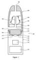
図1は、第一のエアロゾル発生システム100の断面図を示す。エアロゾル発生システム100は、エアロゾル発生装置150およびカートリッジ200を備える。この実施例では、エアロゾル発生システム100は電気的に作動する喫煙システムである。 FIG. 1 shows a cross-sectional view of a first
エアロゾル発生装置150は携帯可能であり、従来の葉巻たばこまたは紙巻たばこに匹敵するサイズを有する。装置150は、リン酸リチウム鉄電池などの電池152、および電池152に電気的に接続されたコントローラ154を備える。装置150はまた、電池152に電気的に接続された二つの電気接点156、158を備える。この電気的接続は有線接続であり、図1には示されていない。図1では、エアロゾル発生装置150は、カートリッジ200と係合している。この実施例では、カートリッジ200は、エアロゾル発生装置150の対応するねじ山162と嵌合したカートリッジ200のねじ山206を介して、エアロゾル発生装置150と係合している。
カートリッジ200は、第一の電気接点214および第二の電気接点216、空気吸込み口202、空気出口204、および第一のヒーター組立品300を備える。空気吸込み口202は、空気出口204と流体連通する。ヒーター組立品300は、空気吸込み口202の下流かつ空気出口204の上流に位置付けられる。ヒーター組立品300は、液体エアロゾル形成基体の貯蔵部303と流体連通する保持材料302を含む。貯蔵部303は、ヒーター組立品300とは別個の構成要素として本明細書に記載されている。しかしながら、一部の実施形態では、貯蔵部300は、ヒーター組立品の一部を形成する。ヒーター組立品300はまた、螺旋形状の発熱体304を備える。第一の電気接点214および第二の電気接点216は、発熱体304に電気的に接続されている。気流経路306は、保持材料302の中心を通して画定される。
このシステム100では、液体エアロゾル形成基体は、約74重量%のグリセリン、24重量%のプロピレングリコール、および2重量%のニコチンを含むが、任意の適切な基体が使用されうる。大気圧において、ニコチンは約247℃の沸点を有し、グリセリンは約290℃の沸点を有し、プロピレングリコールは約188℃の沸点を有する。よって、エアロゾルを形成するためにこの液体エアロゾル形成基体を最初に加熱するとき、一部のシステムは、不相応に大量のプロピレングリコール(基体を形成する化合物の最も低い沸点を有する)を望ましくないほど蒸発させうる。これは、所望の割合よりも少ないニコチンを含むエアロゾルなど、望ましくないエアロゾルがユーザーに送達されるという結果につながりうる。これはまた、より長い時間にわたって、基体中の化合物の相対的割合を望ましくないほど変化させうる。本発明は、これらの望ましくない効果を排除するか、または少なくとも低減しうる。 In this
使用時、ユーザーは、カートリッジ200の空気出口204を吸煙する。同時に、ユーザーは、エアロゾル発生装置150上のボタン(図示せず)を押す。このボタンを押すと、コントローラ154に信号が送られ、その結果、電池152から、装置の電気接点156、158およびカートリッジの電気接点214、216を介して発熱体304に電力が供給される。これにより、発熱体304を通して電流が流れ、それによって発熱体304を抵抗加熱する。他の実施例では、空気流センサー、または圧力センサーは、カートリッジ200内に位置し、コントローラ154に電気的に接続される。空気流センサーまたは圧力センサーは、ユーザーがカートリッジ200の空気出口204を吸煙していることを検出し、コントローラ154に信号を送信して、発熱体304に電力を供給する。したがって、これらの実施例では、発熱体304を加熱するためにユーザーがボタンを押す必要はない。 In use, the user inhales through the
ユーザーがカートリッジ200の空気出口204を吸煙するにつれて、空気は空気吸込み口202の中に引き出される。次に、この空気は、貯蔵部303を通して画定されたチャネル313を通り、次いで保持材料306を通して画定された気流経路306を通って空気出口204に向かって移動する。この空気の流れは、発熱体304が、液体エアロゾル形成基体の貯蔵構成要素302中の液体エアロゾル形成基体を加熱することによって形成されるベイパーを同伴する。この同伴されたベイパーはその後冷却され、凝縮してエアロゾルを形成する。次いで、このエアロゾルは、空気出口204を介してユーザーに送達される。保持材料302中の液体エアロゾル形成基体が加熱され、気化され、気流に同伴されると、貯蔵部303からの液体エアロゾル形成基体が保持材料302の中に移動する。貯蔵部303からのこの液体エアロゾル形成基体は、気化された液体エアロゾル形成基体を効果的に置き換える。貯蔵部303からの液体エアロゾル形成基体は、少なくとも部分的に毛細管作用によって保持材料302の中に引き込まれうる。これは、液体エアロゾル形成基体の貯蔵構成要素302が、繊維構造を有する毛細管材料であるためである。この実施例の保持材料302は、繊維構造を有する毛細管材料である。図1に示す実施例では、毛細管材料は、ポリエステルから形成されるが、任意の適切な材料が使用されうる。 As the user smokes the
ヒーター組立品は、エアロゾル発生システムの残りの部分とは別個にヒーター組立品300を示す、図2および図3にさらに明確に示されている。 The heater assembly is shown more clearly in FIGS. 2 and 3, which show
図2は、ヒーター組立品300の斜視図を示し、これは発熱体304がどのように螺旋形状であり、先端を切断した螺旋の形態を有するかを示す。発熱体304の螺旋形状は、保持材料302で充填された内部体積を画定する。内部体積の断面積は、螺旋形状の中心を通して画定された長軸方向軸に沿って減少する。内部体積を満たす保持材料302は、先端を切断した円錐形状を有する。発熱体304は、材料の細片である。この実施例では、材料はステンレス鋼であるが、任意の適切な材料が使用されうる。 FIG. 2 shows a perspective view of the
発熱体304は、その長さに沿って均一な断面積、ならびにその長さに沿って均一な厚さおよび幅を有する。発熱体304は、その長さに沿って均一な抵抗を有する。したがって、使用時および電力が発熱体304に供給されるとき、発熱体304の加熱力は、発熱体304の長さに沿って実質的に一定である。しかしながら、発熱体304によって画定される内部体積の幾何学的形状のために、保持材料の中央は、より高い温度の領域およびより低い温度の領域を含む。これは、図3により明確に示されている。
図3は、ヒーター組立品300の断面図を示す。保持材料302で充填された内部体積の三つの中央領域は、点線で示されている。三つの中央領域は、長軸方向軸に沿って間隙を介している。第一の中央領域312は、第二の中央領域310と第三の中央領域308との間に位置する。第二の中央領域310は、内部体積の断面積が最小である長軸方向軸の第一の端に向かって位置する。第三の中央領域308は、内部体積の断面積が最大である長軸方向軸の第二の端に向かって位置する。使用時、気流経路306を通過する空気は、第三の中央領域308、第一の中央領域312および第二の中央領域310を順次通過する。 FIG. 3 shows a cross-sectional view of
上述のように、保持材料302の内部体積の断面積は、長軸方向軸に沿って減少する。熱は発熱体から保持要素へと伝導によって伝達されるので、第一の中央領域および第二の中央領域の温度は、発熱体と保持材料のそれぞれの中央領域との間の最短距離に依存する。保持材料の体積の断面積がより小さい場合、発熱体304は、保持材料の中央により近い。図3に示すように、第一の中央領域312よりも発熱体304に近い第二の中央領域310は、同様に、第三の中央領域308よりも発熱体304に近い。これは、内部体積を充填する保持材料の不均一な加熱をもたらし、第三の中央領域308は、第一の中央領域312よりも低い温度に加熱され、同様に、第二の中央領域310よりも低い温度に加熱される。 As discussed above, the cross-sectional area of the internal volume of
第一の中央領域312、第二の中央領域310および第三の中央領域308の間の温度差は、第一の中央領域312で発生したベイパーが、第二の中央領域310および第三の中央領域308で発生したベイパーと比較して、異なる重量比のニコチンを含むという結果をもたらす。同様に、第一の中央領域で発生したベイパーは、第二の中央領域および第三の中央領域と比較して、異なる重量比のグリセロールおよびプロピレングリコールを含む。特に、最も低い沸点を有するプロピレングリコールは、最も低温の第三の中央領域で気化され、プロピレングリコールよりも高い沸点を有するニコチンは、主に中間の第一の中央領域312で気化され、最も高い沸点を有するグリセロールは、最も高温の第二の中央領域310で気化される。 The temperature difference between the first
保持材料302の中央領域間の温度差は、例えば、最初の発熱体の作動の後など、ヒーター組立品が熱平衡状態にないときに特に顕著である。これは、保持材料を加熱するための初めの発熱体の作動と、保持要素の中央領域が最大温度に達することとの間に、ずれまたは遅延が生じるためである。ずれまたは遅延の程度は、保持材料の熱伝導率に依存する。発熱体とそれぞれの中央領域との間の距離が大きいほど、最大温度に到達するまでのずれまたは遅延が長くなる。 The temperature difference between the central regions of the retaining
気流経路306は、第一の中央領域312、第二の中央領域310、および第三の中央領域308を、長軸方向軸に平行な方向に通過する。気流経路306は、使用時、空気が、最大の断面積を有する保持材料302の端から気流経路に入るように配設されてもよい。言い換えれば、第三の中央領域308を最初に通過する。動作中、第三の中央領域308は、最も低温である。ヒーター組立品が動作しているとき、入ってくる空気は保持材料302よりもかなり低温である。したがって、気流経路に入る空気は有利なことに、第三の中央領域を冷却するように作用してもよい。空気が第一の中央領域312そして第二の中央領域310に到達するとき、空気はヒーター組立品によって加熱されており、そのため空気の冷却効果は減少する。したがって、気流経路306のこうした配設は、第三の中央領域、第一の中央領域および第二の中央領域との間の温度差を増大させる。
図4および図5は、第一の発熱体404および第二の発熱体405を含む第二のヒーター組立品400を示す。図4は、第二のヒーター組立品400の斜視図を示し、図5は、断面図を示す。第一の発熱体404および第二の発熱体405の両方が段付けされ、発熱体が共に漸進的により近くなるように構成された三つの段を含む。これは、図5に最も明確に示されている。第一の発熱体404と第二の発熱体405との間に、保持材料402で充填された内部体積が画定される。内部体積の断面積は、段付き発熱体の結果として長軸方向軸に沿って減少する。長軸方向軸は、内部体積の中央を通して画定される。第一の発熱体404および第二の発熱体405は、両方とも形作られた材料の細片である。この実施例では、材料はステンレス鋼であるが、任意の適切な材料が使用されうる。 4 and 5 illustrate a
図5は、発熱体404、405によって画定される内部体積の三つの中央領域を示す。三つの中央領域は、破線で示されている。三つの中央領域は、長軸方向軸に沿って間隙を介している。第一の中央領域412は、第二の中央領域410と第三の中央領域408との間に位置する。第二の中央領域410は、内部体積の断面積が最小である長軸方向軸の第一の端に向かって位置する。第三の中央領域408は、内部体積の断面積が最大である長軸方向軸の第二の端に向かって位置する。使用時、気流経路406を通過する空気は、第三の中央領域408、第一の中央領域412および第二の中央領域410を順次通過する。使用時、気流経路306を通過する空気は、第三の中央領域408、第一の中央領域412および第二の中央領域410を順次通過する。 FIG. 5 shows three central regions of the internal volume defined by
したがって、第一のヒーター組立品と同様に、第二のヒーター組立品は、第一の中央部分、第二の中央部分、および第三の中央部分が異なる方向である配設を提供する。 Thus, like the first heater assembly, the second heater assembly provides an arrangement in which the first central portion, the second central portion, and the third central portion are in different orientations.
図6は、第三のヒーター組立品500を示す。第三のヒーター組立品500は、第一のヒーター組立品および第二のヒーター組立品で示すような単一の気流経路ではなく、二つの気流経路506、507を備える。発熱体304によって画定される内部体積は、保持材料502で充填されている。第一の気流経路506は、内部体積の第一の中央領域508を通して画定される。第二の気流経路507は、内部体積の第二の中央領域510を通して画定される。当然ながら、内部体積は、第一の領域508と中央領域510との間および両側の他の中央領域を含む。しかしながら、図6は、これらの中央領域を通して画定される気流経路を示していない。一部の実施形態では、ヒーター組立品500は、保持材料の異なる中央領域を通過する追加の気流経路を含むことができる。 FIG. 6 shows a
その他すべての点において、第三のヒーター組立品500は、第一のヒーター組立品300と同一である。 In all other respects,
図7は、第四のヒーター組立品を示す。第四のヒーター組立品600は、螺旋形状の発熱体604を備える。螺旋形状の発熱体は、発熱体の幅が、内部体積の断面積が減少するのと同じ方向に長軸方向軸に沿って減少するという点で、第一のヒーター組立品の発熱体304とは異なる。その他すべての点において、第四のヒーター組立品600は、第一のヒーター組立品300と同一である。 Figure 7 shows a fourth heater assembly. The
発熱体604の抵抗は、幅が減少するにつれて増加する。したがって、使用時に、発熱体は、その長さに沿ってより高温になる。これにより、第一の中央領域および第二の中央領域の温度差が増加する。したがって、こうした温度勾配を有する発熱体を提供することは、第一の化合物および第二の化合物の気化の制御の増大を可能にする。 The resistance of
図8は、第二のエアロゾル発生システム800の概略断面図を示す。エアロゾル発生システム800は、エアロゾル発生装置850と、第二のヒーター組立品700を組み込んだカートリッジ900とを備える。この実施例では、エアロゾル発生システム800は電気的に作動する喫煙システムである。 FIG. 8 shows a schematic cross-sectional view of a second
エアロゾル発生装置850は携帯可能であり、従来の葉巻たばこまたは紙巻たばこに匹敵するサイズを有する。装置850は、リン酸リチウム鉄電池などの電池852、および電池852に電気的に接続されたコントローラ854を備える。装置850はまた、電池852に電気的に接続された誘導コイル856を備える。装置850はまた、空気吸込み口858および空気吸込み口858と流体連通する空気出口860を備える。
カートリッジ900は、空気吸込み口902、空気出口904、および第二のヒーター組立品700を備える。空気吸込み口902は、空気出口904と流体連通している。ヒーター組立品700は、空気吸込み口902の下流かつ空気出口904の上流に位置付けられる。図8に示すように、カートリッジ500がエアロゾル発生装置850と係合するとき、装置850の空気出口860は、カートリッジ900の空気吸込み口802に隣接している。よって、使用時、ユーザーがカートリッジ900の空気出口904を吸煙すると、空気は装置850の空気吸込み口858を通り、次いで装置850の空気出口860を通り、次いでカートリッジ900の空気吸込み口902を通り、次いでヒーター組立品700を通り、次いでカートリッジ900の空気出口904から出る。
このシステム800では、液体エアロゾル形成基体は、約98重量%のグリセリン、および2重量%のニコチンを含むが、任意の適切な基体が使用されうる。大気圧において、ニコチンは約247℃の沸点を有し、グリセリンは約290℃の沸点を有する。よって、エアロゾルを形成するためにこの液体エアロゾル形成基体を最初に加熱するとき、一部のシステムは、不相応に大量のニコチン(基体を形成する化合物の最も低い沸点を有する)を望ましくないほど蒸発させうる。これは、望ましくないエアロゾルがユーザーに送達されることにつながりうる。これはまた、より長い時間にわたって、基体中の化合物の相対的割合を望ましくないほど変化させうる。本発明は、これらの望ましくない効果を排除するか、または少なくとも低減しうる。 In this
図8では、エアロゾル発生装置900は、カートリッジ850と係合している。この実施例では、カートリッジ900は、エアロゾル発生装置850上の対応する突出部862、864とスナップ嵌合接続を形成する開口部906、908を介して、エアロゾル発生装置850と係合する。 In FIG. 8,
ヒーター組立品700は、螺旋形状の発熱体704と、螺旋形状の発熱体によって画定される内部体積を満たす保持材料702とを含む。これは、図1に関連して記載される第一のヒーター組立品300と類似の配設である。発熱体704は、サセプタ材料の細片を含む。この実施例では、サセプタ材料はアルミニウムであるが、任意の適切なサセプタ材料が使用されうる。
この実施例の保持材料702は、繊維構造を有する毛細管材料である。毛細管材料は、ポリエステルから形成されるが、任意の適切な材料が使用されてもよい。 The
使用時、ユーザーは、カートリッジ900の空気出口704を吸煙する。同時に、ユーザーは、エアロゾル発生装置850上のボタン(図示せず)を押す。このボタンを押すことによりコントローラ854に信号が送られ、その結果、電池852が高周波電流を誘導コイル856に供給する。これにより、誘導コイル856が変動電磁場を生成する。発熱体704は、この磁場内に位置付けられる。よって、この変動電磁場は、発熱体704内に渦電流およびヒステリシス損失を発生させる。したがって、発熱体704は誘導加熱される。他の実施例では、空気流センサー、または圧力センサーは、装置850内に位置し、コントローラ854に電気的に接続される。気流センサーまたは圧力センサーは、ユーザーがカートリッジ900の空気出口904を吸煙していることを検出し、コントローラ854に信号を送信して、高周波電流を誘導コイル856に供給し、それによって発熱体904を加熱する。したがって、これらの実施例では、発熱体704を加熱するためにユーザーがボタンを押す必要はない。 In use, a user inhales through
発熱体704が加熱されると、保持材料702に、より高い温度の領域およびより低い温度の領域が生成される。より高い温度の領域およびより低い温度の領域の生成により、保持材料602中のより高い沸点および低い沸点を有する液体エアロゾル形成基体の化合物が同時に気化する。この効果は、図1に示すエアロゾル発生システムに関連して上述した。 As
ユーザーがカートリッジ900の空気出口904を吸煙すると、空気が空気吸込み口858の中に引き出される。次に、この空気は、貯蔵部803を通して画定されたチャネル813を通り、次いで保持材料702を通して画定された気流経路806を通って空気出口904に向かって移動する。この空気の流れは、保持材料703中の液体エアロゾル形成基体の加熱によって形成されるベイパーを同伴する。この同伴されたベイパーはその後冷却され、凝縮してエアロゾルを形成する。次に、この空気は、空気出口904に向かって移動する。この空気の流れは、発熱体704による液体エアロゾル形成基体の加熱によって形成されるベイパーを同伴する。この同伴されたベイパーはその後冷却され、凝縮してエアロゾルを形成する。次いで、このエアロゾルは、空気出口904を介してユーザーに送達される。 When a user smokes
図9は、代替的な誘導加熱機構を使用する第六のヒーター組立品1000を示す。第六のヒーター組立品1000は、第一の発熱体1004および第二の発熱体1005を含む。第一の発熱体1004および第二の発熱体1005の両方は、ポリアミドで作られた電気的に絶縁された基体を含む。電気的に絶縁された基体は、三つの段を含む段付き形状を有する。段は、発熱体が共に漸進的により近くなるように構成されている。各発熱体1004、1005は、段のそれぞれの上の平坦な螺旋の形態の誘導コイル1008を含む。誘導コイル1008は、電気的に絶縁された基体に取り付けられるか、または埋め込まれている。 FIG. 9 shows a
第一の発熱体1004と第二の発熱体1005との間に、保持材料1002で充填された内部体積が画定される。内部体積の断面積は、段付き発熱体の結果として長軸方向軸に沿って減少する。長軸方向軸は、内部体積の中央を通して画定される。気流経路1006は、長軸方向軸に平行に、保持材料の中心を通して画定される。これは、図4および図5に示すものと類似した配設である。しかしながら、この実施形態では、平坦な螺旋コイルの形状のインダクタコイル1008は、発熱体のそれぞれの上に形成される。 An interior volume filled with retaining
さらに、保持材料1006は、サセプタ材料から成る。この実施形態では、サセプタ材料は発泡金属から成るが、任意の適切な材料を使用することができる。誘導コイルを含む発熱体は、エアロゾル発生システムの電池に接続される。これは図9には示されていない。 Furthermore, the retaining
使用時に、エアロゾル発生システムのコントローラに信号が送られ、その結果、発熱体1004、1005の誘導コイル1008に高周波電流が電池から供給される。これにより、誘導コイル1008が変動電磁場を生成する。サセプタ材料から成る保持材料1006は、この磁場内に位置付けられる。よって、この変動電磁場は、保持材料1002内に渦電流およびヒステリシス損失を発生させる。したがって、保持材料1002は誘導加熱される。 In use, a signal is sent to the controller of the aerosol generation system so that the
保持材料1002の温度は、交番磁界の磁束密度または磁界強度に依存する。誘導コイル間の磁束密度は、誘導コイルが共に近づくにつれて増加する。したがって、以前の実施形態に関連して記載したように、保持材料は、発熱体1004、1005の異なる段に対応して、異なるゾーンでは異なる温度に加熱される。保持材料1006の第一の中央領域は、第二の中央領域または第三の中央領域とは異なる温度に加熱される。これは図9には示されていない。 The temperature of the holding
図10は、第七のヒーター組立品1100の断面概略図を示す。第七のヒーター組立品1100は、第一の発熱体1104および第二の発熱体1105を含む。図9のヒーター組立品1000と同様に、第一の発熱体1004および第二の発熱体1005の両方は、ポリアミドで作られた電気的に絶縁された基体を含む。第一の発熱体1104および第二の発熱体1105の両方の電気的に絶縁された基体が段付けされ、発熱体が共に漸進的により近くなるように構成された三つの段を含む。各発熱体1104、1105は、段のそれぞれの上の平坦な螺旋の形態の誘導コイル(図10には図示せず)を含む。 FIG. 10 shows a cross-sectional schematic view of a
第一の発熱体1004と第二の発熱体1005との間に、保持材料1102で充填された内部体積が画定される。内部体積の断面積は、段付き発熱体の結果として長軸方向軸に沿って減少する。長軸方向軸は、内部体積の中央を通して画定される。気流経路1006は、長軸方向軸に平行に、保持材料1102の中心を通して画定される。これは、図9に示すものと類似した配設である。しかしながら、図10に示す実施形態では、保持材料はサセプタ材料から成ってはいない。代わりに、サセプタ材料は、気流経路1106を囲む円筒形メッシュ1103の形態で提供される。 An interior volume filled with retaining
使用時に、エアロゾル発生システム(図10には図示せず)のコントローラに信号が送られ、その結果、発熱体1004、1005の誘導コイルに高周波電流が電池から供給される。これにより、誘導コイル1008が変動電磁場を生成する。サセプタ材料から成る保持材料1002は、この磁場内に位置付けられる。よって、この変動電磁場は、円筒形メッシュ1103内に渦電流およびヒステリシス損失を発生させる。したがって、円筒形メッシュ1103は誘導加熱され、その熱が保持材料1102に伝導され、その保持材料1102に含有されるエアロゾル形成基体を加熱する。 In use, a signal is sent to the controller of the aerosol generation system (not shown in FIG. 10), which causes the induction coils of the
保持材料1106の温度は、交番磁界の磁束密度または磁界強度に依存する。インダクタコイル間の磁束密度は、インダクタコイルが共に近づくにつれて増加する。したがって、以前の実施形態に関連して記載したように、保持材料は、発熱体1104、1105の異なる段に対応して、異なる中央領域1108、1110、1112では異なる温度に加熱される。 The temperature of the retaining
Claims (15)
Translated fromJapanese凝縮形態のエアロゾル形成基体を含有する保持材料であって、前記エアロゾル形成基体が第一の化合物および第二の化合物を含み、前記第二の化合物が前記第一の化合物よりも高い沸点を有する、保持材料と、
前記保持材料を通して画定された少なくとも一つの気流経路と、
内部体積を画定するように形作られた少なくとも一つの発熱体であって、前記内部体積が前記保持材料で充填されている、少なくとも一つの発熱体と、を備え、
前記内部体積は、長軸方向軸に沿って減少する断面積を有し、
前記少なくとも一つの気流経路が、前記内部体積の第一の中央領域および前記内部体積の第二の中央領域を通過し、前記第一の中央領域および前記第二の中央領域は前記長軸方向軸に沿って間隙を介している、ヒーター組立品。A heater assembly for use in an aerosol generation system, the heater assembly comprising:
a retention material containing an aerosol-forming substrate in condensed form, the aerosol-forming substrate comprising a first compound and a second compound, the second compound having a higher boiling point than the first compound; a retaining material;
at least one airflow path defined through the retention material;
at least one heating element shaped to define an interior volume, the interior volume being filled with the retaining material;
the internal volume has a cross-sectional area that decreases along a longitudinal axis;
the at least one airflow path passing through a first central region of the internal volume and a second central region of the internal volume, the first central region and the second central region being aligned with the longitudinal axis; The heater assembly has a gap along it.
前記電源から前記ヒーター組立品に供給される電力を制御するためのコントローラと、をさらに備える、請求項11に記載のエアロゾル発生システム。a power source connectable to the heater assembly;
12. The aerosol generation system of claim 11, further comprising a controller for controlling power provided to the heater assembly from the power source.
凝縮形態のエアロゾル形成基体を含有する保持材料であって、前記エアロゾル形成基体が第一の化合物および第二の化合物を含み、前記第二の化合物は前記第一の化合物よりも高い沸点を有する、保持材料と、
前記保持材料を通して画定された少なくとも一つの気流経路と、
内部体積を画定するように形作られた少なくとも一つの発熱体を含むヒーター組立品であって、前記内部体積が前記保持材料で充填されている、ヒーター組立品と、
電源と、
前記電源から前記ヒーター組立品に供給される前記電力を制御するためのコントローラと、を備え、
前記内部体積が、長軸方向軸に沿って減少する断面積を有し、
前記少なくとも一つの気流経路が、前記内部体積の第一の中央領域および前記内部体積の第二の中央領域を通過し、前記第一の中央領域および前記第二の中央領域が前記長軸方向軸に沿って間隙を介しており、
前記方法が、前記第一の中央領域が前記第二の中央領域とは異なる温度に加熱されるように、前記少なくとも一つの発熱体を起動して前記保持材料を加熱することを含む、方法。A method of using an aerosol generation system, the aerosol generation system comprising:
a retention material containing an aerosol-forming substrate in condensed form, the aerosol-forming substrate comprising a first compound and a second compound, the second compound having a higher boiling point than the first compound; a retaining material;
at least one airflow path defined through the retention material;
a heater assembly including at least one heating element shaped to define an interior volume, the interior volume being filled with the retention material;
power supply and
a controller for controlling the power supplied to the heater assembly from the power source;
the internal volume has a cross-sectional area that decreases along a longitudinal axis;
The at least one airflow path passes through a first central region of the internal volume and a second central region of the internal volume, the first central region and the second central region being aligned with the longitudinal axis. with a gap along the
The method comprises activating the at least one heating element to heat the retention material such that the first central region is heated to a different temperature than the second central region.
Applications Claiming Priority (3)
| Application Number | Priority Date | Filing Date | Title |
|---|---|---|---|
| EP20216453 | 2020-12-22 | ||
| EP20216453.9 | 2020-12-22 | ||
| PCT/EP2021/085511WO2022136002A1 (en) | 2020-12-22 | 2021-12-13 | Heater assembly for use in an aerosol-generating system |
Publications (2)
| Publication Number | Publication Date |
|---|---|
| JP2023554058Atrue JP2023554058A (en) | 2023-12-26 |
| JPWO2022136002A5 JPWO2022136002A5 (en) | 2024-12-18 |
Family
ID=73856790
Family Applications (1)
| Application Number | Title | Priority Date | Filing Date |
|---|---|---|---|
| JP2023536375APendingJP2023554058A (en) | 2020-12-22 | 2021-12-13 | Heater assembly for use in aerosol generation systems |
Country Status (6)
| Country | Link |
|---|---|
| US (1) | US20240032599A1 (en) |
| EP (1) | EP4266921B1 (en) |
| JP (1) | JP2023554058A (en) |
| KR (1) | KR20230124626A (en) |
| CN (1) | CN116583198A (en) |
| WO (1) | WO2022136002A1 (en) |
Families Citing this family (2)
| Publication number | Priority date | Publication date | Assignee | Title |
|---|---|---|---|---|
| WO2024200753A1 (en)* | 2023-03-29 | 2024-10-03 | Philip Morris Products S.A. | Heater assembly with shaped porous body |
| WO2025021619A1 (en)* | 2023-07-25 | 2025-01-30 | Jt International Sa | Consumable article with a heating arrangement for an aerosol-generating system |
Family Cites Families (6)
| Publication number | Priority date | Publication date | Assignee | Title |
|---|---|---|---|---|
| US10058123B2 (en)* | 2014-07-11 | 2018-08-28 | R. J. Reynolds Tobacco Company | Heater for an aerosol delivery device and methods of formation thereof |
| CN204070562U (en)* | 2014-08-12 | 2015-01-07 | 深圳市合元科技有限公司 | Atomizers for electronic cigarettes and electronic cigarettes |
| US11129413B2 (en)* | 2017-03-13 | 2021-09-28 | Altria Client Services Llc | Three-piece electronic vaping device with planar heater |
| US10674765B2 (en)* | 2017-03-29 | 2020-06-09 | Rai Strategic Holdings, Inc. | Aerosol delivery device with improved atomizer |
| US11785677B2 (en)* | 2017-06-08 | 2023-10-10 | Altria Client Services Llc | Cartridge having a susceptor material |
| CN110279162B (en)* | 2019-07-30 | 2024-11-08 | 深圳雾芯科技有限公司 | Atomization device and method thereof |
- 2021
- 2021-12-13JPJP2023536375Apatent/JP2023554058A/enactivePending
- 2021-12-13USUS18/257,790patent/US20240032599A1/enactivePending
- 2021-12-13KRKR1020237024093Apatent/KR20230124626A/enactivePending
- 2021-12-13EPEP21839407.0Apatent/EP4266921B1/enactiveActive
- 2021-12-13WOPCT/EP2021/085511patent/WO2022136002A1/ennot_activeCeased
- 2021-12-13CNCN202180081685.5Apatent/CN116583198A/enactivePending
Also Published As
| Publication number | Publication date |
|---|---|
| EP4266921B1 (en) | 2025-02-05 |
| EP4266921A1 (en) | 2023-11-01 |
| US20240032599A1 (en) | 2024-02-01 |
| EP4266921C0 (en) | 2025-02-05 |
| KR20230124626A (en) | 2023-08-25 |
| CN116583198A (en) | 2023-08-11 |
| WO2022136002A1 (en) | 2022-06-30 |
Similar Documents
| Publication | Publication Date | Title |
|---|---|---|
| JP7399711B2 (en) | Aerosol generation system with variable airflow | |
| JP7698023B2 (en) | Aerosol generation system providing preferential evaporation of nicotine | |
| JP7171887B2 (en) | heater having at least two adjacent metal meshes | |
| CN110169600B (en) | Aerosol-generating system and method of manufacture | |
| CN113015448B (en) | Aerosol generating system and cartridge with leakage protection | |
| JP2020501555A (en) | Aerosol generation system with cartridge with side opening | |
| CN113749311A (en) | Cartridge for an aerosol-generating system | |
| JP2024500706A (en) | heater assembly | |
| CN113286527A (en) | Nebulizer and aerosol-generating system comprising a nebulizer | |
| CN111936000A (en) | Heater assembly having a heater element isolated from a liquid supply | |
| JP2024500099A (en) | heater assembly | |
| JP2023554058A (en) | Heater assembly for use in aerosol generation systems | |
| JP2023511996A (en) | Cartridge for use in an aerosol-generating system and aerosol-generating system comprising the cartridge | |
| JP2022538972A (en) | Aerosol generating system and cartridge for aerosol generating system with improved heating assembly | |
| JP2024543643A (en) | Hybrid aerosol generation system with modular consumables | |
| JP2024525645A (en) | Aerosol generating system having a sliding mechanism for mechanical sealing and cartridge for the aerosol generating system | |
| EP4266922B1 (en) | Cartridge for use in an aerosol-generating system |
Legal Events
| Date | Code | Title | Description |
|---|---|---|---|
| A521 | Request for written amendment filed | Free format text:JAPANESE INTERMEDIATE CODE: A523 Effective date:20241210 | |
| A621 | Written request for application examination | Free format text:JAPANESE INTERMEDIATE CODE: A621 Effective date:20241210 |