JP2023551688A - battery pack - Google Patents
battery packDownload PDFInfo
- Publication number
- JP2023551688A JP2023551688AJP2023532593AJP2023532593AJP2023551688AJP 2023551688 AJP2023551688 AJP 2023551688AJP 2023532593 AJP2023532593 AJP 2023532593AJP 2023532593 AJP2023532593 AJP 2023532593AJP 2023551688 AJP2023551688 AJP 2023551688A
- Authority
- JP
- Japan
- Prior art keywords
- battery
- battery pack
- pack assembly
- housing
- assembly
- Prior art date
- Legal status (The legal status is an assumption and is not a legal conclusion. Google has not performed a legal analysis and makes no representation as to the accuracy of the status listed.)
- Pending
Links
Images


Classifications
- H—ELECTRICITY
- H01—ELECTRIC ELEMENTS
- H01M—PROCESSES OR MEANS, e.g. BATTERIES, FOR THE DIRECT CONVERSION OF CHEMICAL ENERGY INTO ELECTRICAL ENERGY
- H01M50/00—Constructional details or processes of manufacture of the non-active parts of electrochemical cells other than fuel cells, e.g. hybrid cells
- H01M50/20—Mountings; Secondary casings or frames; Racks, modules or packs; Suspension devices; Shock absorbers; Transport or carrying devices; Holders
- H01M50/204—Racks, modules or packs for multiple batteries or multiple cells
- H01M50/207—Racks, modules or packs for multiple batteries or multiple cells characterised by their shape
- H01M50/213—Racks, modules or packs for multiple batteries or multiple cells characterised by their shape adapted for cells having curved cross-section, e.g. round or elliptic
- H—ELECTRICITY
- H01—ELECTRIC ELEMENTS
- H01M—PROCESSES OR MEANS, e.g. BATTERIES, FOR THE DIRECT CONVERSION OF CHEMICAL ENERGY INTO ELECTRICAL ENERGY
- H01M10/00—Secondary cells; Manufacture thereof
- H01M10/42—Methods or arrangements for servicing or maintenance of secondary cells or secondary half-cells
- H01M10/425—Structural combination with electronic components, e.g. electronic circuits integrated to the outside of the casing
- H—ELECTRICITY
- H01—ELECTRIC ELEMENTS
- H01M—PROCESSES OR MEANS, e.g. BATTERIES, FOR THE DIRECT CONVERSION OF CHEMICAL ENERGY INTO ELECTRICAL ENERGY
- H01M10/00—Secondary cells; Manufacture thereof
- H01M10/60—Heating or cooling; Temperature control
- H01M10/61—Types of temperature control
- H01M10/613—Cooling or keeping cold
- H—ELECTRICITY
- H01—ELECTRIC ELEMENTS
- H01M—PROCESSES OR MEANS, e.g. BATTERIES, FOR THE DIRECT CONVERSION OF CHEMICAL ENERGY INTO ELECTRICAL ENERGY
- H01M10/00—Secondary cells; Manufacture thereof
- H01M10/60—Heating or cooling; Temperature control
- H01M10/61—Types of temperature control
- H01M10/615—Heating or keeping warm
- H—ELECTRICITY
- H01—ELECTRIC ELEMENTS
- H01M—PROCESSES OR MEANS, e.g. BATTERIES, FOR THE DIRECT CONVERSION OF CHEMICAL ENERGY INTO ELECTRICAL ENERGY
- H01M10/00—Secondary cells; Manufacture thereof
- H01M10/60—Heating or cooling; Temperature control
- H01M10/62—Heating or cooling; Temperature control specially adapted for specific applications
- H01M10/623—Portable devices, e.g. mobile telephones, cameras or pacemakers
- H01M10/6235—Power tools
- H—ELECTRICITY
- H01—ELECTRIC ELEMENTS
- H01M—PROCESSES OR MEANS, e.g. BATTERIES, FOR THE DIRECT CONVERSION OF CHEMICAL ENERGY INTO ELECTRICAL ENERGY
- H01M10/00—Secondary cells; Manufacture thereof
- H01M10/60—Heating or cooling; Temperature control
- H01M10/64—Heating or cooling; Temperature control characterised by the shape of the cells
- H01M10/643—Cylindrical cells
- H—ELECTRICITY
- H01—ELECTRIC ELEMENTS
- H01M—PROCESSES OR MEANS, e.g. BATTERIES, FOR THE DIRECT CONVERSION OF CHEMICAL ENERGY INTO ELECTRICAL ENERGY
- H01M10/00—Secondary cells; Manufacture thereof
- H01M10/60—Heating or cooling; Temperature control
- H01M10/65—Means for temperature control structurally associated with the cells
- H01M10/653—Means for temperature control structurally associated with the cells characterised by electrically insulating or thermally conductive materials
- H—ELECTRICITY
- H01—ELECTRIC ELEMENTS
- H01M—PROCESSES OR MEANS, e.g. BATTERIES, FOR THE DIRECT CONVERSION OF CHEMICAL ENERGY INTO ELECTRICAL ENERGY
- H01M10/00—Secondary cells; Manufacture thereof
- H01M10/60—Heating or cooling; Temperature control
- H01M10/65—Means for temperature control structurally associated with the cells
- H01M10/655—Solid structures for heat exchange or heat conduction
- H01M10/6551—Surfaces specially adapted for heat dissipation or radiation, e.g. fins or coatings
- H—ELECTRICITY
- H01—ELECTRIC ELEMENTS
- H01M—PROCESSES OR MEANS, e.g. BATTERIES, FOR THE DIRECT CONVERSION OF CHEMICAL ENERGY INTO ELECTRICAL ENERGY
- H01M10/00—Secondary cells; Manufacture thereof
- H01M10/60—Heating or cooling; Temperature control
- H01M10/65—Means for temperature control structurally associated with the cells
- H01M10/655—Solid structures for heat exchange or heat conduction
- H01M10/6554—Rods or plates
- H01M10/6555—Rods or plates arranged between the cells
- H—ELECTRICITY
- H01—ELECTRIC ELEMENTS
- H01M—PROCESSES OR MEANS, e.g. BATTERIES, FOR THE DIRECT CONVERSION OF CHEMICAL ENERGY INTO ELECTRICAL ENERGY
- H01M10/00—Secondary cells; Manufacture thereof
- H01M10/60—Heating or cooling; Temperature control
- H01M10/65—Means for temperature control structurally associated with the cells
- H01M10/656—Means for temperature control structurally associated with the cells characterised by the type of heat-exchange fluid
- H01M10/6561—Gases
- H01M10/6563—Gases with forced flow, e.g. by blowers
- H01M10/6565—Gases with forced flow, e.g. by blowers with recirculation or U-turn in the flow path, i.e. back and forth
- H—ELECTRICITY
- H01—ELECTRIC ELEMENTS
- H01M—PROCESSES OR MEANS, e.g. BATTERIES, FOR THE DIRECT CONVERSION OF CHEMICAL ENERGY INTO ELECTRICAL ENERGY
- H01M10/00—Secondary cells; Manufacture thereof
- H01M10/60—Heating or cooling; Temperature control
- H01M10/65—Means for temperature control structurally associated with the cells
- H01M10/656—Means for temperature control structurally associated with the cells characterised by the type of heat-exchange fluid
- H01M10/6561—Gases
- H01M10/6566—Means within the gas flow to guide the flow around one or more cells, e.g. manifolds, baffles or other barriers
- H—ELECTRICITY
- H01—ELECTRIC ELEMENTS
- H01M—PROCESSES OR MEANS, e.g. BATTERIES, FOR THE DIRECT CONVERSION OF CHEMICAL ENERGY INTO ELECTRICAL ENERGY
- H01M10/00—Secondary cells; Manufacture thereof
- H01M10/60—Heating or cooling; Temperature control
- H01M10/65—Means for temperature control structurally associated with the cells
- H01M10/657—Means for temperature control structurally associated with the cells by electric or electromagnetic means
- H01M10/6571—Resistive heaters
- H—ELECTRICITY
- H01—ELECTRIC ELEMENTS
- H01M—PROCESSES OR MEANS, e.g. BATTERIES, FOR THE DIRECT CONVERSION OF CHEMICAL ENERGY INTO ELECTRICAL ENERGY
- H01M50/00—Constructional details or processes of manufacture of the non-active parts of electrochemical cells other than fuel cells, e.g. hybrid cells
- H01M50/20—Mountings; Secondary casings or frames; Racks, modules or packs; Suspension devices; Shock absorbers; Transport or carrying devices; Holders
- H01M50/233—Mountings; Secondary casings or frames; Racks, modules or packs; Suspension devices; Shock absorbers; Transport or carrying devices; Holders characterised by physical properties of casings or racks, e.g. dimensions
- H01M50/24—Mountings; Secondary casings or frames; Racks, modules or packs; Suspension devices; Shock absorbers; Transport or carrying devices; Holders characterised by physical properties of casings or racks, e.g. dimensions adapted for protecting batteries from their environment, e.g. from corrosion
- H—ELECTRICITY
- H01—ELECTRIC ELEMENTS
- H01M—PROCESSES OR MEANS, e.g. BATTERIES, FOR THE DIRECT CONVERSION OF CHEMICAL ENERGY INTO ELECTRICAL ENERGY
- H01M50/00—Constructional details or processes of manufacture of the non-active parts of electrochemical cells other than fuel cells, e.g. hybrid cells
- H01M50/20—Mountings; Secondary casings or frames; Racks, modules or packs; Suspension devices; Shock absorbers; Transport or carrying devices; Holders
- H01M50/247—Mountings; Secondary casings or frames; Racks, modules or packs; Suspension devices; Shock absorbers; Transport or carrying devices; Holders specially adapted for portable devices, e.g. mobile phones, computers, hand tools or pacemakers
- H—ELECTRICITY
- H01—ELECTRIC ELEMENTS
- H01M—PROCESSES OR MEANS, e.g. BATTERIES, FOR THE DIRECT CONVERSION OF CHEMICAL ENERGY INTO ELECTRICAL ENERGY
- H01M50/00—Constructional details or processes of manufacture of the non-active parts of electrochemical cells other than fuel cells, e.g. hybrid cells
- H01M50/20—Mountings; Secondary casings or frames; Racks, modules or packs; Suspension devices; Shock absorbers; Transport or carrying devices; Holders
- H01M50/262—Mountings; Secondary casings or frames; Racks, modules or packs; Suspension devices; Shock absorbers; Transport or carrying devices; Holders with fastening means, e.g. locks
- H01M50/264—Mountings; Secondary casings or frames; Racks, modules or packs; Suspension devices; Shock absorbers; Transport or carrying devices; Holders with fastening means, e.g. locks for cells or batteries, e.g. straps, tie rods or peripheral frames
- H—ELECTRICITY
- H01—ELECTRIC ELEMENTS
- H01M—PROCESSES OR MEANS, e.g. BATTERIES, FOR THE DIRECT CONVERSION OF CHEMICAL ENERGY INTO ELECTRICAL ENERGY
- H01M50/00—Constructional details or processes of manufacture of the non-active parts of electrochemical cells other than fuel cells, e.g. hybrid cells
- H01M50/20—Mountings; Secondary casings or frames; Racks, modules or packs; Suspension devices; Shock absorbers; Transport or carrying devices; Holders
- H01M50/284—Mountings; Secondary casings or frames; Racks, modules or packs; Suspension devices; Shock absorbers; Transport or carrying devices; Holders with incorporated circuit boards, e.g. printed circuit boards [PCB]
- H—ELECTRICITY
- H01—ELECTRIC ELEMENTS
- H01M—PROCESSES OR MEANS, e.g. BATTERIES, FOR THE DIRECT CONVERSION OF CHEMICAL ENERGY INTO ELECTRICAL ENERGY
- H01M50/00—Constructional details or processes of manufacture of the non-active parts of electrochemical cells other than fuel cells, e.g. hybrid cells
- H01M50/20—Mountings; Secondary casings or frames; Racks, modules or packs; Suspension devices; Shock absorbers; Transport or carrying devices; Holders
- H01M50/296—Mountings; Secondary casings or frames; Racks, modules or packs; Suspension devices; Shock absorbers; Transport or carrying devices; Holders characterised by terminals of battery packs
- H—ELECTRICITY
- H01—ELECTRIC ELEMENTS
- H01M—PROCESSES OR MEANS, e.g. BATTERIES, FOR THE DIRECT CONVERSION OF CHEMICAL ENERGY INTO ELECTRICAL ENERGY
- H01M50/00—Constructional details or processes of manufacture of the non-active parts of electrochemical cells other than fuel cells, e.g. hybrid cells
- H01M50/50—Current conducting connections for cells or batteries
- H01M50/502—Interconnectors for connecting terminals of adjacent batteries; Interconnectors for connecting cells outside a battery casing
- H01M50/507—Interconnectors for connecting terminals of adjacent batteries; Interconnectors for connecting cells outside a battery casing comprising an arrangement of two or more busbars within a container structure, e.g. busbar modules
- H—ELECTRICITY
- H01—ELECTRIC ELEMENTS
- H01M—PROCESSES OR MEANS, e.g. BATTERIES, FOR THE DIRECT CONVERSION OF CHEMICAL ENERGY INTO ELECTRICAL ENERGY
- H01M50/00—Constructional details or processes of manufacture of the non-active parts of electrochemical cells other than fuel cells, e.g. hybrid cells
- H01M50/50—Current conducting connections for cells or batteries
- H01M50/502—Interconnectors for connecting terminals of adjacent batteries; Interconnectors for connecting cells outside a battery casing
- H01M50/509—Interconnectors for connecting terminals of adjacent batteries; Interconnectors for connecting cells outside a battery casing characterised by the type of connection, e.g. mixed connections
- H—ELECTRICITY
- H01—ELECTRIC ELEMENTS
- H01M—PROCESSES OR MEANS, e.g. BATTERIES, FOR THE DIRECT CONVERSION OF CHEMICAL ENERGY INTO ELECTRICAL ENERGY
- H01M50/00—Constructional details or processes of manufacture of the non-active parts of electrochemical cells other than fuel cells, e.g. hybrid cells
- H01M50/50—Current conducting connections for cells or batteries
- H01M50/502—Interconnectors for connecting terminals of adjacent batteries; Interconnectors for connecting cells outside a battery casing
- H01M50/514—Methods for interconnecting adjacent batteries or cells
- H01M50/516—Methods for interconnecting adjacent batteries or cells by welding, soldering or brazing
- H—ELECTRICITY
- H01—ELECTRIC ELEMENTS
- H01M—PROCESSES OR MEANS, e.g. BATTERIES, FOR THE DIRECT CONVERSION OF CHEMICAL ENERGY INTO ELECTRICAL ENERGY
- H01M2220/00—Batteries for particular applications
- H01M2220/30—Batteries in portable systems, e.g. mobile phone, laptop
- Y—GENERAL TAGGING OF NEW TECHNOLOGICAL DEVELOPMENTS; GENERAL TAGGING OF CROSS-SECTIONAL TECHNOLOGIES SPANNING OVER SEVERAL SECTIONS OF THE IPC; TECHNICAL SUBJECTS COVERED BY FORMER USPC CROSS-REFERENCE ART COLLECTIONS [XRACs] AND DIGESTS
- Y02—TECHNOLOGIES OR APPLICATIONS FOR MITIGATION OR ADAPTATION AGAINST CLIMATE CHANGE
- Y02E—REDUCTION OF GREENHOUSE GAS [GHG] EMISSIONS, RELATED TO ENERGY GENERATION, TRANSMISSION OR DISTRIBUTION
- Y02E60/00—Enabling technologies; Technologies with a potential or indirect contribution to GHG emissions mitigation
- Y02E60/10—Energy storage using batteries
Landscapes
- Chemical & Material Sciences (AREA)
- Chemical Kinetics & Catalysis (AREA)
- Electrochemistry (AREA)
- General Chemical & Material Sciences (AREA)
- Engineering & Computer Science (AREA)
- Manufacturing & Machinery (AREA)
- Life Sciences & Earth Sciences (AREA)
- Biophysics (AREA)
- Computer Hardware Design (AREA)
- Microelectronics & Electronic Packaging (AREA)
- Physics & Mathematics (AREA)
- Electromagnetism (AREA)
- Battery Mounting, Suspending (AREA)
- Secondary Cells (AREA)
- Connection Of Batteries Or Terminals (AREA)
Abstract
Translated fromJapanese
Description
Translated fromJapanese 関連出願の相互参照
本出願は、2021年5月28日に出願された、同時係属中の米国仮特許出願第63/194,614号明細書の優先権を主張するものであり、また2021年3月8日に出願された、同時係属中の中国特許出願第202110252873.1号明細書及び2020年12月4日に出願された、同時係属中の中国特許出願第202011411151.8号明細書の外国優先権を主張するものであり、これらのすべての内容全体が、参照により本明細書に組み込まれる。CROSS-REFERENCE TO RELATED APPLICATIONS This application claims priority to co-pending U.S. Provisional Patent Application No. 63/194,614, filed May 28, 2021, and Co-pending Chinese Patent Application No. 202110252873.1 filed on March 8th and co-pending Chinese Patent Application No. 202011411151.8 filed on December 4th, 2020. Foreign priority is claimed, all of the contents of which are incorporated herein by reference in their entirety.
本発明は、密閉型バッテリパックに関し、より詳細には、密閉されたハウジング内の熱冷却を促進するように構成されたバッテリパックの内部構造に関する。 TECHNICAL FIELD The present invention relates to sealed battery packs, and more particularly to internal structures of battery packs configured to promote thermal cooling within a sealed housing.
一般に、動力工具などの電気機器は、充電式バッテリパックによって電力供給され得る。バッテリパックは、対応するバッテリ充電器において充電され得る。 Generally, electrical equipment, such as power tools, may be powered by a rechargeable battery pack. The battery pack can be charged in a corresponding battery charger.
本明細書で開示される一態様では、ハウジングと、バッテリセルアセンブリと、ファンとを備えるバッテリパックアセンブリが提供される。ハウジングは、複数の側面を有し、内部空洞を画定する。バッテリセルアセンブリは、内部空洞に配置される。バッテリセルアセンブリは、複数のバッテリセルとバッテリセルを支持するフレームとを備える。フレームは、第1の支持部材と、第2の支持部材と、第1の支持部材及び第2の支持部材を接続する複数の脚部材とを備える。第1の支持部材及び第2の支持部材はそれぞれ、第1の縁部と、第1の縁部とは反対側にある第2の縁部との間に延びる本体を有する。本体は、バッテリセルのうちの1つと整列するように構成された複数の開口部を画定する。ファンは、ハウジング内、及びバッテリセルアセンブリを通して空気を循環させるように構成される。 In one aspect disclosed herein, a battery pack assembly is provided that includes a housing, a battery cell assembly, and a fan. The housing has multiple sides and defines an interior cavity. A battery cell assembly is disposed within the interior cavity. The battery cell assembly includes a plurality of battery cells and a frame that supports the battery cells. The frame includes a first support member, a second support member, and a plurality of leg members connecting the first support member and the second support member. The first support member and the second support member each have a body extending between a first edge and a second edge opposite the first edge. The body defines a plurality of openings configured to align with one of the battery cells. The fan is configured to circulate air within the housing and through the battery cell assembly.
いくつかの実施形態では、バッテリパックアセンブリが、ハウジングと一体化されたヒートシンクを更に備える。 In some embodiments, the battery pack assembly further includes a heat sink integrated with the housing.
いくつかの実施形態では、バッテリパックアセンブリが、内部空洞内に配置された複数のバッフルを更に備える。 In some embodiments, the battery pack assembly further comprises a plurality of baffles disposed within the interior cavity.
いくつかの実施形態では、バッフルのそれぞれが、バッテリセルアセンブリに向かって空気流を導くように配置される。 In some embodiments, each of the baffles is positioned to direct airflow toward the battery cell assembly.
いくつかの実施形態では、バッテリパックアセンブリが、高出力バッテリパックとして構成され、様々な原動機付き動力工具に接続可能であり、電力供給するように動作可能である。 In some embodiments, the battery pack assembly is configured as a high power battery pack and is connectable and operable to power various motorized power tools.
いくつかの実施形態では、バッテリセルアセンブリが、バッテリセルのそれぞれがハウジングの縦軸に対して向けられるように内部空洞内に配置される。 In some embodiments, a battery cell assembly is positioned within the interior cavity such that each of the battery cells is oriented relative to a longitudinal axis of the housing.
いくつかの実施形態では、バッテリセルのそれぞれが、対応するバッテリセルに隣接して配置されたコネクタにワイヤによって接続される。 In some embodiments, each of the battery cells is connected by a wire to a connector located adjacent to the corresponding battery cell.
いくつかの実施形態では、コネクタが、導電性プレートであり、バッテリセルのうちの少なくとも2つに直接結合される。 In some embodiments, the connector is a conductive plate and is coupled directly to at least two of the battery cells.
いくつかの実施形態では、コネクタが、第2の支持部材の側面に配置される。 In some embodiments, a connector is placed on a side of the second support member.
いくつかの実施形態では、バッテリパックアセンブリが、バッテリ端子接点を更に備える。 In some embodiments, the battery pack assembly further includes battery terminal contacts.
いくつかの実施形態では、バッテリセルアセンブリが、バッテリパックアセンブリ内でバッテリ端子接点に電気的に接続される。 In some embodiments, a battery cell assembly is electrically connected to battery terminal contacts within a battery pack assembly.
いくつかの実施形態では、第1の支持部材及び第2の支持部材が、内部空洞内でバッテリセルの位置を維持するように構成される。 In some embodiments, the first support member and the second support member are configured to maintain the position of the battery cell within the interior cavity.
いくつかの実施形態では、第1の支持部材が、ハウジングの内面に隣接して配置される。 In some embodiments, a first support member is positioned adjacent an interior surface of the housing.
いくつかの実施形態では、第1の支持部材が、ハウジングの内面に結合される。 In some embodiments, a first support member is coupled to an interior surface of the housing.
いくつかの実施形態では、バッテリパックアセンブリが、バッテリエレクトロニクスを更に備える。 In some embodiments, the battery pack assembly further includes battery electronics.
いくつかの実施形態では、内部空洞内でバッテリセルアセンブリ又はバッテリエレクトロニクスが占有しない空間が、バッテリセルアセンブリを囲むように配置される1つ又は複数の空気流チャネルに分割される。 In some embodiments, the space within the interior cavity not occupied by the battery cell assembly or battery electronics is divided into one or more airflow channels disposed around the battery cell assembly.
いくつかの実施形態では、バッテリパックアセンブリが、ハウジングの上面に配置された空気流トンネルを更に備える。 In some embodiments, the battery pack assembly further includes an airflow tunnel located on the top surface of the housing.
いくつかの実施形態では、空気流トンネルが、ハウジングの内部空洞と流体連通する。 In some embodiments, an airflow tunnel is in fluid communication with the interior cavity of the housing.
いくつかの実施形態では、空気流トンネルが、空気流を受け入れ、空気流をバッテリセルに向かって戻るように案内するための曲線形状を有する。 In some embodiments, the airflow tunnel has a curved shape to receive the airflow and guide the airflow back toward the battery cells.
いくつかの実施形態では、空気流トンネルが、バッテリセルアセンブリの周囲及びバッテリセルアセンブリ内に配置された隣接するバッテリセル間の間隙に、ファンによって循環される空気の一部を導くように構成されたデフレクタを備える。 In some embodiments, the airflow tunnel is configured to direct a portion of the air circulated by the fan around the battery cell assembly and into gaps between adjacent battery cells disposed within the battery cell assembly. equipped with a deflector.
いくつかの実施形態では、デフレクタが端部部分と2つの案内部材とを有する。 In some embodiments, the deflector has an end portion and two guide members.
いくつかの実施形態では、バッテリセルが、熱伝導性ギャップフィラー、接着剤、ポッティング、又は封止剤によって、空気流トンネル、デフレクタ、又は端部部分に熱的に結合されて、ハウジング又はハウジングの部分を密閉する。 In some embodiments, the battery cell is thermally coupled to the airflow tunnel, deflector, or end portion of the housing or the housing by a thermally conductive gap filler, adhesive, potting, or sealant. Seal the part.
いくつかの実施形態では、ファンが、バッテリセルアセンブリに隣接して配置される。 In some embodiments, a fan is positioned adjacent the battery cell assembly.
いくつかの実施形態では、バッテリセルが、金属スリーブ又はプラスチックスリーブに配置される。 In some embodiments, the battery cells are placed in a metal or plastic sleeve.
いくつかの実施形態では、ハウジング又はハウジングのうちのバッテリセルを囲む部分が、ファンがバッテリパックアセンブリの外部からの空気を交換し得るようにするために密閉されない。 In some embodiments, the housing or a portion of the housing surrounding the battery cell is not sealed to allow a fan to exchange air from outside the battery pack assembly.
いくつかの実施形態では、バッテリセルのそれぞれが等間隔に配置される。 In some embodiments, each of the battery cells is equally spaced.
いくつかの実施形態では、バッテリセルの隣接する列が、縦方向、鉛直方向、及び横方向に整列される。 In some embodiments, adjacent columns of battery cells are longitudinally, vertically, and laterally aligned.
いくつかの実施形態では、バッテリセルの隣接する列が、千鳥状に配置され、互いに対してオフセットされる。 In some embodiments, adjacent rows of battery cells are staggered and offset with respect to each other.
本明細書で開示される別の態様では、ハウジングと、バッテリセルアセンブリと、ファンと、空気流トンネルとを備えるバッテリパックアセンブリが提供される。ハウジングは、内部空洞を画定する。バッテリセルアセンブリは、内部空洞に配置される。バッテリセルアセンブリは、複数のバッテリセルとバッテリセルを支持するフレームとを備える。ファンは、ハウジング内、及びバッテリセルアセンブリを通して空気を循環させるように構成される。空気流トンネルは、ハウジングの上面に配置され、ハウジングの内部空洞と流体連通する。空気流トンネルは、バッテリセルアセンブリの周囲及びバッテリセルアセンブリ内に配置された隣接するバッテリセル間の間隙に、ファンによって循環される空気の一部を導くように構成されたデフレクタを備える。 In another aspect disclosed herein, a battery pack assembly is provided that includes a housing, a battery cell assembly, a fan, and an airflow tunnel. The housing defines an interior cavity. A battery cell assembly is disposed within the interior cavity. The battery cell assembly includes a plurality of battery cells and a frame that supports the battery cells. The fan is configured to circulate air within the housing and through the battery cell assembly. An airflow tunnel is disposed on the top surface of the housing and is in fluid communication with the interior cavity of the housing. The airflow tunnel includes a deflector configured to direct a portion of the air circulated by the fan around the battery cell assembly and into gaps between adjacent battery cells disposed within the battery cell assembly.
いくつかの実施形態では、ハウジングが、空気が内部空洞に存在しないように密閉される。 In some embodiments, the housing is sealed so that no air is present in the internal cavity.
いくつかの実施形態では、バッテリパックアセンブリが、ハウジングと一体化されたヒートシンクを更に備える。 In some embodiments, the battery pack assembly further includes a heat sink integrated with the housing.
いくつかの実施形態では、バッテリパックアセンブリが、内部空洞内に配置された複数のバッフルを更に備える。 In some embodiments, the battery pack assembly further comprises a plurality of baffles disposed within the interior cavity.
いくつかの実施形態では、バッフルのそれぞれが、バッテリセルアセンブリに向かって空気流を導くように配置される。 In some embodiments, each of the baffles is positioned to direct airflow toward the battery cell assembly.
いくつかの実施形態では、バッテリパックアセンブリが、高出力バッテリパックとして構成され、様々な原動機付き動力工具に接続可能であり、電力供給するように動作可能である。 In some embodiments, the battery pack assembly is configured as a high power battery pack and is connectable and operable to power various motorized power tools.
いくつかの実施形態では、バッテリセルアセンブリが、バッテリセルのそれぞれがハウジングの縦軸に対して向けられるように内部空洞内に配置される。 In some embodiments, a battery cell assembly is positioned within the interior cavity such that each of the battery cells is oriented relative to a longitudinal axis of the housing.
いくつかの実施形態では、フレームが、第1の支持部材と、第2の支持部材と、第1の支持部材及び第2の支持部材を接続する複数の脚部材とを備える。 In some embodiments, the frame includes a first support member, a second support member, and a plurality of leg members connecting the first support member and the second support member.
いくつかの実施形態では、第1の支持部材及び第2の支持部材がそれぞれ、第1の縁部と、第1の縁部とは反対側にある第2の縁部との間に延びる本体を有する。 In some embodiments, the first support member and the second support member each extend between a first edge and a second edge opposite the first edge. has.
いくつかの実施形態では、本体が、バッテリセルのうちの1つと整列するように構成された複数の開口部を画定する。 In some embodiments, the body defines a plurality of openings configured to align with one of the battery cells.
いくつかの実施形態では、第1の支持部材及び第2の支持部材が、内部空洞内でバッテリセルの位置を維持するように構成される。 In some embodiments, the first support member and the second support member are configured to maintain the position of the battery cell within the interior cavity.
いくつかの実施形態では、第1の支持部材が、ハウジングの内面に隣接して配置される。 In some embodiments, a first support member is positioned adjacent an interior surface of the housing.
いくつかの実施形態では、第1の支持部材が、ハウジングの内面に結合される。 In some embodiments, a first support member is coupled to an interior surface of the housing.
いくつかの実施形態では、バッテリセルのそれぞれが、対応するバッテリセルに隣接して配置されたコネクタにワイヤによって接続される。 In some embodiments, each of the battery cells is connected by a wire to a connector located adjacent to the corresponding battery cell.
いくつかの実施形態では、コネクタが、導電性プレートであり、バッテリセルのうちの少なくとも2つに直接結合される。 In some embodiments, the connector is a conductive plate and is coupled directly to at least two of the battery cells.
いくつかの実施形態では、コネクタが、第2の支持部材の側面に配置される。 In some embodiments, a connector is placed on a side of the second support member.
いくつかの実施形態では、バッテリパックアセンブリが、バッテリ端子接点を更に備える。 In some embodiments, the battery pack assembly further includes battery terminal contacts.
いくつかの実施形態では、バッテリセルアセンブリが、バッテリパックアセンブリ内でバッテリ端子接点に電気的に接続される。 In some embodiments, a battery cell assembly is electrically connected to battery terminal contacts within a battery pack assembly.
いくつかの実施形態では、バッテリパックアセンブリが、バッテリエレクトロニクスを更に備える。 In some embodiments, the battery pack assembly further includes battery electronics.
いくつかの実施形態では、内部空洞内でバッテリセルアセンブリ又はバッテリエレクトロニクスが占有しない空間が、バッテリセルアセンブリを囲むように配置される1つ又は複数の空気流チャネルに分割される。 In some embodiments, the space within the interior cavity not occupied by the battery cell assembly or battery electronics is divided into one or more airflow channels disposed around the battery cell assembly.
いくつかの実施形態では、空気流トンネルが、空気流を受け入れ、空気流をバッテリセルに向かって戻るように案内するための曲線形状を有する。 In some embodiments, the airflow tunnel has a curved shape to receive the airflow and guide the airflow back toward the battery cells.
いくつかの実施形態では、デフレクタが端部部分と2つの案内部材とを有する。 In some embodiments, the deflector has an end portion and two guide members.
いくつかの実施形態では、バッテリセルが、熱伝導性ギャップフィラー、接着剤、ポッティング、又は封止剤によって、空気流トンネル、デフレクタ、又は端部部分に熱的に結合されて、ハウジング又はハウジングの部分を密閉する。 In some embodiments, the battery cell is thermally coupled to the airflow tunnel, deflector, or end portion of the housing or the housing by a thermally conductive gap filler, adhesive, potting, or sealant. Seal the part.
いくつかの実施形態では、ファンが、バッテリセルアセンブリに隣接して配置される。 In some embodiments, a fan is positioned adjacent the battery cell assembly.
いくつかの実施形態では、バッテリセルが、金属スリーブ又はプラスチックスリーブに配置される。 In some embodiments, the battery cells are placed in a metal or plastic sleeve.
いくつかの実施形態では、ハウジング又はハウジングのうちのバッテリセルを囲む部分が、ファンがバッテリパックアセンブリの外部からの空気を交換し得るようにするために密閉されない。 In some embodiments, the housing or a portion of the housing surrounding the battery cell is not sealed to allow a fan to exchange air from outside the battery pack assembly.
いくつかの実施形態では、バッテリセルのそれぞれが等間隔に配置される。 In some embodiments, each of the battery cells is equally spaced.
いくつかの実施形態では、バッテリセルの隣接する列が、縦方向、鉛直方向、及び横方向に整列される。 In some embodiments, adjacent columns of battery cells are longitudinally, vertically, and laterally aligned.
いくつかの実施形態では、バッテリセルの隣接する列が、千鳥状に配置され、互いに対してオフセットされる。 In some embodiments, adjacent rows of battery cells are staggered and offset with respect to each other.
本明細書で開示される更に別の態様では、ハウジングと、ハウジングに受け入れられた1つ又は複数のバッテリセルアセンブリとを備えるバッテリパックアセンブリが提供される。1つ又は複数のバッテリセルアセンブリのそれぞれが、内部に内部空洞を少なくとも部分的に画定するフレームと、内部空洞に配置された複数のバッテリセルと、ヒートシンクとを備える。ヒートシンクは、第1の面と、第1の面とは反対側にある第2の面とを有する本体を備える。ヒートシンクは、第1の面から延びる複数のフィンと、第2の面から延びる複数の突起とを更に備える。フィンは内部空洞の外部にあり、複数の突起は内部空洞内に配置される。突起は、バッテリセルと突起とが内部空洞内で少なくとも一方向に順に配置されるようにバッテリセル間に配置される。 In yet another aspect disclosed herein, a battery pack assembly is provided that includes a housing and one or more battery cell assemblies received within the housing. Each of the one or more battery cell assemblies includes a frame at least partially defining an interior cavity therein, a plurality of battery cells disposed within the interior cavity, and a heat sink. The heat sink includes a body having a first surface and a second surface opposite the first surface. The heat sink further includes a plurality of fins extending from the first surface and a plurality of protrusions extending from the second surface. The fins are external to the internal cavity and the plurality of protrusions are disposed within the internal cavity. The protrusions are disposed between the battery cells such that the battery cells and the protrusions are sequentially disposed in at least one direction within the interior cavity.
いくつかの実施形態では、突起のうちの1つ又は複数が、部分的に内部に延びるチャネルを備え、1つ又は複数のバッテリセルアセンブリのそれぞれが、チャネルのそれぞれに受け入れられた加熱ロッドを更に備える。 In some embodiments, one or more of the protrusions includes a partially extending channel, and each of the one or more battery cell assemblies further includes a heating rod received in each of the channels. Be prepared.
いくつかの実施形態では、ヒートシンクの本体が複数の開口部を備え、各開口部がチャネルのうちの1つに接続され、加熱ロッドが対応する開口部を通ってチャネルに挿入される。 In some embodiments, the body of the heat sink includes a plurality of openings, each opening connected to one of the channels, and a heating rod inserted into the channel through the corresponding opening.
いくつかの実施形態では、開口部のそれぞれが、ヒートシンクの本体の第1の面にある複数のフィンのうちのいくつかの間に配置される。 In some embodiments, each of the openings is disposed between some of the plurality of fins on the first side of the body of the heat sink.
いくつかの実施形態では、各加熱ロッドの端部が、対応する整列したチャネル及び開口部の外部に配置される。 In some embodiments, the end of each heating rod is positioned outside a corresponding aligned channel and opening.
いくつかの実施形態では、1つ又は複数のバッテリセルアセンブリのそれぞれが、内部空洞に配置された接着材料を備える。接着材料は、突起及びバッテリセルに接触する。接着材料は、バッテリセルと突起との間における熱伝達を促進するために熱伝導性である。 In some embodiments, each of the one or more battery cell assemblies includes an adhesive material disposed within the interior cavity. An adhesive material contacts the protrusion and the battery cell. The adhesive material is thermally conductive to facilitate heat transfer between the battery cell and the protrusion.
いくつかの実施形態では、複数の突起のそれぞれが本体の第2の面から端部まで延び、複数の突起のそれぞれがバッテリセルのそれぞれに平行に延び、突起のそれぞれの端部がバッテリセルのうちの1つの端部に隣接して配置される。 In some embodiments, each of the plurality of protrusions extends from the second surface of the body to the end, each of the plurality of protrusions extends parallel to a respective one of the battery cells, and each end of the plurality of protrusions extends parallel to a respective one of the battery cells. located adjacent to one end of the.
いくつかの実施形態では、フレームが複数の支持部材を備える。各支持部材は、バッテリセルと複数の突起のうちの隣接する1つの突起との間に配置され得る。支持部材のそれぞれが、バッテリセルのうちの1つと内部空洞の突起のうちの1つとを位置決めするように構成され得る。 In some embodiments, the frame includes multiple support members. Each support member may be disposed between the battery cell and one adjacent protrusion of the plurality of protrusions. Each of the support members may be configured to position one of the battery cells and one of the protrusions of the internal cavity.
いくつかの実施形態では、バッテリパックアセンブリが、ハウジング内に、1つ又は複数のバッテリセルアセンブリに近接して配置されたファンアセンブリを備える。ファンアセンブリは、1つ又は複数のバッテリセルアセンブリのフィンを通過するように空気流を導くように動作可能である。 In some embodiments, the battery pack assembly includes a fan assembly disposed within the housing and proximate the one or more battery cell assemblies. The fan assembly is operable to direct airflow past the fins of the one or more battery cell assemblies.
いくつかの実施形態では、バッテリパックアセンブリが、フレームに結合されたカバーを更に備える。フレーム、カバー、及びヒートシンクの本体の第2の面が、協働して内部空洞を画定し得る。 In some embodiments, the battery pack assembly further includes a cover coupled to the frame. The frame, cover, and second surface of the heat sink body may cooperate to define an interior cavity.
いくつかの実施形態では、バッテリパックアセンブリが、フレームによって支持された複数のコネクタを更に備え、コネクタのそれぞれがバッテリセルのうちの2つ以上に接続される。 In some embodiments, the battery pack assembly further comprises a plurality of connectors supported by the frame, each connector connected to two or more of the battery cells.
本明細書で開示される更に別の態様では、ハウジングと、ハウジングに受け入れられた1つ又は複数のバッテリセルアセンブリとを備えるバッテリパックアセンブリが提供される。1つ又は複数のバッテリセルアセンブリのそれぞれが、内部に内部空洞を少なくとも部分的に画定するフレームと、内部空洞に配置された複数のバッテリセルと、ヒートシンクとを備える。ヒートシンクは、第1の面と、第1の面とは反対側にある第2の面とを有する本体を備える。ヒートシンクは、第2の面から延びる複数の突起を更に備える。第1の面は内部空洞の外部にあり、複数の突起は内部空洞内に配置される。突起のうちの1つ又は複数が、内部に部分的に延びるチャネルを備える。バッテリセルアセンブリのうちの1つ又は複数が、複数の加熱ロッドを更に備える。各加熱ロッドが、チャネルのうちの1つに受け入れられる。突起は、バッテリセルと突起とが内部空洞内で順に配置されるようにバッテリセル間に配置される。 In yet another aspect disclosed herein, a battery pack assembly is provided that includes a housing and one or more battery cell assemblies received within the housing. Each of the one or more battery cell assemblies includes a frame at least partially defining an interior cavity therein, a plurality of battery cells disposed within the interior cavity, and a heat sink. The heat sink includes a body having a first surface and a second surface opposite the first surface. The heat sink further includes a plurality of protrusions extending from the second surface. The first surface is external to the interior cavity and the plurality of projections are disposed within the interior cavity. One or more of the protrusions includes a channel that partially extends therein. One or more of the battery cell assemblies further include a plurality of heating rods. Each heating rod is received in one of the channels. The protrusions are disposed between the battery cells such that the battery cells and the protrusions are sequentially disposed within the interior cavity.
いくつかの実施形態では、突起のうちの1つ又は複数が、部分的に内部に延びるチャネルを備え、1つ又は複数のバッテリセルアセンブリのそれぞれが、チャネルのそれぞれに受け入れられた加熱ロッドを更に備える。 In some embodiments, one or more of the protrusions includes a partially extending channel, and each of the one or more battery cell assemblies further includes a heating rod received in each of the channels. Be prepared.
いくつかの実施形態では、ヒートシンクの本体が複数の開口部を備え、各開口部がチャネルのうちの1つに接続され、加熱ロッドが対応する開口部を通ってチャネルに挿入される。 In some embodiments, the body of the heat sink includes a plurality of openings, each opening connected to one of the channels, and a heating rod inserted into the channel through the corresponding opening.
いくつかの実施形態では、1つ又は複数のバッテリセルアセンブリのそれぞれが、内部空洞に配置された接着材料を備え、接着材料が、突起及びバッテリセルに接触し、接着材料が、バッテリセルと突起との間における熱伝達を促進するために熱伝導性である。 In some embodiments, each of the one or more battery cell assemblies includes an adhesive material disposed in the interior cavity, the adhesive material contacting the protrusion and the battery cell, and the adhesive material contacting the battery cell and the protrusion. It is thermally conductive to facilitate heat transfer between the
いくつかの実施形態では、複数の突起のそれぞれが本体の第2の面から端部まで延び、複数の突起のそれぞれがバッテリセルのそれぞれに平行に延び、突起のそれぞれの端部がバッテリセルのうちの1つの端部に隣接して配置される。 In some embodiments, each of the plurality of protrusions extends from the second surface of the body to the end, each of the plurality of protrusions extends parallel to a respective one of the battery cells, and each end of the plurality of protrusions extends parallel to a respective one of the battery cells. located adjacent to one end of the.
いくつかの実施形態では、バッテリパックアセンブリが、フレームに結合されたカバーを更に備える。フレーム、カバー、及びヒートシンクの本体の第2の面が、協働して内部空洞を画定し得る。 In some embodiments, the battery pack assembly further includes a cover coupled to the frame. The frame, cover, and second surface of the heat sink body may cooperate to define an interior cavity.
本明細書で開示される別の態様では、内部に内部空洞を少なくとも部分的に画定するフレームと、内部空洞に配置された複数のバッテリセルと、ヒートシンクとを備える、バッテリパックのためのバッテリセルアセンブリが提供される。ヒートシンクは、第1の面と、第1の面とは反対側にある第2の面とを有する本体を備える。ヒートシンクは、第1の面から延びる複数のフィンと、第2の面から延びる複数の突起とを更に備える。フィンは内部空洞の外部にあり、複数の突起は内部空洞内に配置される。突起のうちの1つ又は複数が、内部に部分的に延びるチャネルを備える。突起は、バッテリセルと突起とが内部空洞内で順に配置されるようにバッテリセル間に配置される。 In another aspect disclosed herein, a battery cell for a battery pack includes a frame at least partially defining an interior cavity therein, a plurality of battery cells disposed in the interior cavity, and a heat sink. Assembly provided. The heat sink includes a body having a first surface and a second surface opposite the first surface. The heat sink further includes a plurality of fins extending from the first surface and a plurality of protrusions extending from the second surface. The fins are external to the internal cavity and the plurality of protrusions are disposed within the internal cavity. One or more of the protrusions includes a channel that partially extends therein. The protrusions are disposed between the battery cells such that the battery cells and the protrusions are sequentially disposed within the interior cavity.
いくつかの実施形態では、バッテリセルアセンブリが、1つ又は複数の加熱ロッドを更に備え、1つ又は複数の加熱ロッドのそれぞれがチャネルのうちの1つに受け入れられる。 In some embodiments, the battery cell assembly further comprises one or more heating rods, each of the one or more heating rods being received in one of the channels.
いくつかの実施形態では、バッテリセルアセンブリが、内部空洞に配置された接着材料を更に備え、接着材料が、突起及びバッテリセルに接触し、接着材料が、バッテリセルと突起との間における熱伝達を促進するために熱伝導性である。 In some embodiments, the battery cell assembly further comprises an adhesive material disposed in the interior cavity, the adhesive material contacting the protrusion and the battery cell, and the adhesive material facilitating heat transfer between the battery cell and the protrusion. It is thermally conductive to promote.
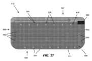
本明細書で開示される更に別の態様では、バッテリパックアセンブリが提供される。バッテリパックアセンブリは、複数の側面を有し、内部空洞を画定するハウジングと、内部空洞に受け入れられた複数のバッテリセルと、内部空洞に受け入れられたバッテリエレクトロニクスとを備える。バッテリパックインターフェースが、ハウジングによって支持され、デバイスに接続可能である。注入ポートがハウジングによって支持される。注入ポートは、ハウジングの側面のうちの1つ又は複数に配置された1つ又は複数のチャネルを備える。各チャネルが、内部空洞をバッテリパックの外部に接続する。注入ポートは、バッテリパックの外部から内部空洞内に、接着材料を含む流体を導くように構成される。流体は、バッテリセルの部分及びバッテリエレクトロニクスの部分の少なくとも一方を覆うように構成される。 In yet another aspect disclosed herein, a battery pack assembly is provided. The battery pack assembly includes a housing having multiple sides and defining an interior cavity, a plurality of battery cells received within the interior cavity, and battery electronics received within the interior cavity. A battery pack interface is supported by the housing and connectable to the device. An injection port is supported by the housing. The injection port comprises one or more channels located on one or more of the sides of the housing. Each channel connects the interior cavity to the exterior of the battery pack. The injection port is configured to direct fluid containing adhesive material from the exterior of the battery pack into the interior cavity. The fluid is configured to cover at least one of the battery cell portion and the battery electronics portion.
いくつかの実施形態では、ハウジングが上部ハウジング部分と底部ハウジング部分とを備え、上部ハウジング部分が注入ポートを備える。 In some embodiments, the housing includes a top housing portion and a bottom housing portion, and the top housing portion includes an injection port.
いくつかの実施形態では、底部ハウジング部分が、内部空洞内で複数のバッテリセルを保持するように構成されたバッテリセルホルダを備え、バッテリセルホルダが、上部ハウジング部分と対向する関係にある表面を備え、表面が、バッテリエレクトロニクスを支持するように構成され、流体が、表面の部分を覆うように構成される。 In some embodiments, the bottom housing portion comprises a battery cell holder configured to hold a plurality of battery cells within the interior cavity, the battery cell holder comprising a surface in opposing relationship with the top housing portion; A surface is configured to support battery electronics, and a fluid is configured to cover a portion of the surface.
いくつかの実施形態では、バッテリエレクトロニクスが、プリント回路基板と、プリント回路基板から延びるバッテリ接点とを備え、バッテリパックインターフェースがバッテリ接点を囲む端子ブロックを備え、流体がプリント回路基板の表面を覆うように構成される。 In some embodiments, the battery electronics includes a printed circuit board and battery contacts extending from the printed circuit board, the battery pack interface includes a terminal block surrounding the battery contacts, and the fluid covers a surface of the printed circuit board. It is composed of
いくつかの実施形態では、ハウジングが、内部に延びる縦軸を備え、注入ポートの1つ又は複数のチャネルのそれぞれが注入軸に沿って延び、注入軸が縦軸に対して角度をなして延びる。 In some embodiments, the housing includes a longitudinal axis extending therein, each of the one or more channels of the injection port extending along the injection axis, and the injection axis extending at an angle to the longitudinal axis. .
いくつかの実施形態では、バッテリエレクトロニクスがプリント回路基板を備え、注入ポートの1つ又は複数のチャネルの端部がプリント回路基板の表面に近接して配置される。 In some embodiments, the battery electronics comprises a printed circuit board, and an end of the channel or channels of the injection port is disposed proximate a surface of the printed circuit board.
いくつかの実施形態では、流体が熱伝導性シリコーン封止材を含む。 In some embodiments, the fluid includes a thermally conductive silicone encapsulant.
本明細書で開示される更に別の態様では、バッテリパックアセンブリの製造方法が提供される。本方法は、バッテリパックアセンブリのハウジングの少なくとも部分を組み立てることと、ハウジングの内部空洞内に複数のバッテリセル及びバッテリエレクトロニクスを配置することと、流体がバッテリセルの部分及びバッテリエレクトロニクスの部分の少なくとも一方を覆うように、ハウジングの注入ポートによって接着材料を含む流体を内部空洞内に注入することとを含む。 In yet another aspect disclosed herein, a method of manufacturing a battery pack assembly is provided. The method includes assembling at least a portion of a housing of a battery pack assembly, disposing a plurality of battery cells and battery electronics within an interior cavity of the housing, and disposing a fluid in at least one of the battery cell portion and the battery electronics portion. injecting a fluid containing adhesive material into the internal cavity through an injection port in the housing so as to cover the adhesive material.
いくつかの実施形態では、ハウジングの少なくとも部分を組み立てることが、バッテリセルホルダを提供することを含み、複数のバッテリセル及びバッテリエレクトロニクスを内部空洞内に配置することが、バッテリセルホルダによって、複数のバッテリセルを受け入れることと、バッテリエレクトロニクスのプリント回路基板をバッテリセルホルダに固定することとを含む。 In some embodiments, assembling at least a portion of the housing includes providing a battery cell holder, and positioning the plurality of battery cells and battery electronics within the internal cavity, the battery cell holder includes providing a plurality of battery cells. and securing the battery electronics printed circuit board to the battery cell holder.
いくつかの実施形態では、流体を注入することが、プリント回路基板の表面を覆うことを含む。 In some embodiments, injecting the fluid includes coating a surface of the printed circuit board.
いくつかの実施形態では、ハウジングの少なくとも部分を組み立てることが、底部ハウジング部分を上部ハウジング部分に結合して内部空洞を形成することを含み、流体を注入することが、注入ポートを使用して上部ハウジング部分を通して流体を注入することを含む。 In some embodiments, assembling at least the portions of the housing includes coupling the bottom housing portion to the top housing portion to form an internal cavity, and injecting the fluid includes connecting the bottom housing portion to the top housing portion using the injection port. including injecting fluid through the housing portion.
いくつかの実施形態では、ハウジングの少なくとも部分を組み立てることが、底部ハウジング部分を組み立てることを含み、本方法が、上部ハウジング部分を底部ハウジング部分に結合する前に、底部ハウジング部分に流体を注入することを更に含む。 In some embodiments, assembling at least a portion of the housing includes assembling a bottom housing portion, and the method includes injecting a fluid into the bottom housing portion before coupling the top housing portion to the bottom housing portion. It further includes:
いくつかの実施形態では、流体が熱伝導性シリコーン封止材を含む。 In some embodiments, the fluid includes a thermally conductive silicone encapsulant.
本明細書で開示される更に別の態様では、バッテリパックアセンブリが提供される。バッテリパックアセンブリは、複数の側面を有し、内部空洞を画定するハウジングと、内部空洞に受け入れられた複数のバッテリセルと、内部空洞に受け入れられたバッテリエレクトロニクスとを備える。バッテリパックインターフェースが、ハウジングによって支持され、デバイスに接続可能である。接着材料を含む層が、内部空洞内でバッテリセルの部分及びバッテリエレクトロニクスの部分とハウジングの複数の内面との間に配置される。層は、バッテリセルの部分及びバッテリエレクトロニクスの部分を覆う連続した表面を有する。層は、層を形成するために硬化されるように構成される流体として、内部空洞に注入可能である。 In yet another aspect disclosed herein, a battery pack assembly is provided. The battery pack assembly includes a housing having multiple sides and defining an interior cavity, a plurality of battery cells received within the interior cavity, and battery electronics received within the interior cavity. A battery pack interface is supported by the housing and connectable to the device. A layer comprising an adhesive material is disposed within the interior cavity between portions of the battery cells and battery electronics and the plurality of interior surfaces of the housing. The layer has a continuous surface covering portions of the battery cells and portions of the battery electronics. The layer is injectable into the internal cavity as a fluid configured to harden to form the layer.
いくつかの実施形態では、バッテリパックアセンブリは、バッテリパックの外部から内部空洞に流体を導くように構成された注入ポートを更に備える。 In some embodiments, the battery pack assembly further comprises an injection port configured to direct fluid from the exterior of the battery pack into the interior cavity.
いくつかの実施形態では、ハウジングが上部ハウジング部分と底部ハウジング部分とを備え、上部ハウジング部分が注入ポートを備える。 In some embodiments, the housing includes a top housing portion and a bottom housing portion, and the top housing portion includes an injection port.
いくつかの実施形態では、底部ハウジング部分が、内部空洞内で複数のバッテリセルを保持するように構成されたバッテリセルホルダを備え、バッテリセルホルダが、上部ハウジング部分と対向する関係にある表面を備え、表面が、バッテリエレクトロニクスを支持するように構成され、層が、表面の部分を覆うように構成される。 In some embodiments, the bottom housing portion comprises a battery cell holder configured to hold a plurality of battery cells within the interior cavity, the battery cell holder comprising a surface in opposing relationship with the top housing portion; A surface is configured to support battery electronics, and a layer is configured to cover a portion of the surface.
いくつかの実施形態では、バッテリエレクトロニクスが、プリント回路基板と、プリント回路基板から延びるバッテリ接点とを備え、バッテリパックインターフェースがバッテリ接点を囲む端子ブロックを備え、層がプリント回路基板の表面を覆うように構成される。 In some embodiments, the battery electronics includes a printed circuit board and battery contacts extending from the printed circuit board, the battery pack interface includes a terminal block surrounding the battery contacts, and the layer covers a surface of the printed circuit board. It is composed of
いくつかの実施形態では、バッテリエレクトロニクスがプリント回路基板を備え、流体が注入ポートによって内部空洞に受け入れられ、注入ポートの端部がプリント回路基板の表面に近接して配置される。 In some embodiments, the battery electronics comprises a printed circuit board, and fluid is received into the interior cavity by an injection port, with an end of the injection port disposed proximate a surface of the printed circuit board.
いくつかの実施形態では、層が熱伝導性シリコーン封止材を含む。 In some embodiments, the layer includes a thermally conductive silicone encapsulant.
本発明の他の独立態様は、詳細な説明及び添付の図面を検討すれば明らかになるはずである。必要に応じて、また適用可能な場合は、1つの態様又は実施形態に関連して本明細書で説明される任意の特徴は、任意の他の態様又は実施形態に関連して本明細書で説明される任意の他の特徴と組み合わされてもよい。 Other independent aspects of the invention will become apparent from consideration of the detailed description and accompanying drawings. Where appropriate and applicable, any feature described herein in connection with one aspect or embodiment may be described herein in connection with any other aspect or embodiment. May be combined with any other features described.
本発明の独立実施形態を詳細に説明する前に、本発明は、以下の説明に記載されているか、又は以下の図面に図示されている構造の細部及び構成要素の配置に本発明の適用を限定されないことを理解されたい。本発明は、他の独立実施形態が可能であり、様々な仕方で実践又は実施することが可能である。 Before describing the independent embodiments of the invention in detail, the invention will be explained in more detail. It should be understood that there is no limitation. The invention is capable of other independent embodiments and of being practiced or carried out in various ways.
「~を含む(including、comprising)」及びそれらの変化形の使用は、本明細書で使用される場合、それに続いて列挙された項目及びその均等物並びに追加の項目を包含することを意味する。本明細書で使用される場合、「からなる(consisting of)」及びその変化形の使用は、その後に列挙される項目及びその均等物のみを包含することを意味する。 The use of "including, comprising" and variations thereof, as used herein, is meant to include the items subsequently listed and their equivalents as well as additional items. . As used herein, the use of "consisting of" and variations thereof is meant to include only the items listed thereafter and their equivalents.
数量又は状態との関連で用いる相対用語、例えば「約」、「略」、「実質的に」などが記載された値を含み、状況によって決まる意味を有する(例えば、この用語は少なくとも測定に関連付けられた誤差の程度、又は公差[例えば、製造、組み立て、使用など]を含む)ことが当業者には理解されよう。このような用語はまた、2個の端点の絶対値により定義される範囲を示すものと見なされたい。例えば、「約2から約4まで」という表現は「2から4まで」の範囲を示す。相対用語は、示された値のある百分率(例えば、1%、5%、10%以上)の増減を指す場合がある。 Relative terms used in connection with quantities or conditions, such as "about," "approximately," "substantially," etc., include the stated value and have the meaning determined by the context (e.g., the term at least Those skilled in the art will appreciate the degree of error or tolerances (including, for example, manufacturing, assembly, use, etc.) that may occur. Such terms should also be considered to indicate a range defined by the absolute values of the two endpoints. For example, the phrase "from about 2 to about 4" indicates a range from "2 to 4." Relative terms may refer to a percentage increase or decrease (eg, 1%, 5%, 10% or more) of the indicated value.
また、本明細書において1つのコンポーネントにより実行されると説明されている機能は、複数のコンポーネントによって分散的に実行されてもよい。同様に、複数のコンポーネントによって実行される機能は、単一のコンポーネントによって統合及び実行されてもよい。同様に、特定の機能を実行するものと説明されている要素は本明細書に記述しない追加的な機能も実行することができる。例えば、特定の仕方で「構成」されたデバイス又は構造は、少なくともその仕方で構成されるが、記載されていない仕方でも構成されてもよい。 Additionally, functions described herein as being performed by one component may be performed in a distributed manner by multiple components. Similarly, functions performed by multiple components may be integrated and performed by a single component. Similarly, elements described as performing a particular function may also perform additional functions not described herein. For example, a device or structure "configured" in a particular way is configured at least that way, but may also be configured in ways not described.
更に、本明細書に記載のいくつかの実施形態は、非一時的コンピュータ可読媒体に記憶された命令を実行することにより、本明細書に記載された機能を実行するように構成された1つ又は複数の電子プロセッサを含み得る。同様に、本明細書に記載の実施形態は、本明細書に記載の機能を実行するために1つ又は複数の電子プロセッサによって実行可能な命令を記憶した非一時的コンピュータ可読媒体として実装され得る。本願で使用されるかぎり、「非一時的コンピュータ可読媒体」はあらゆるコンピュータ可読媒体を含むが、一時的伝播信号からなるものではない。したがって、非一時的コンピュータ可読媒体には、例えばハードディスク、CD-ROM、光記憶装置、磁気記憶装置、読み取り専用メモリ(ROM)、ランダムアクセスメモリ(RAM)、レジスタメモリ、プロセッサキャッシュ、又はこれらの任意の組み合わせが含まれ得る。 Additionally, some embodiments described herein provide a method for performing the functions described herein by executing instructions stored on a non-transitory computer-readable medium. or may include multiple electronic processors. Similarly, embodiments described herein may be implemented as a non-transitory computer-readable medium storing instructions executable by one or more electronic processors to perform the functions described herein. . As used herein, "non-transitory computer-readable media" includes any computer-readable media that does not consist of transitory propagating signals. Thus, non-transitory computer-readable media may include, for example, a hard disk, CD-ROM, optical storage, magnetic storage, read-only memory (ROM), random access memory (RAM), register memory, processor cache, or any of the foregoing. may include combinations of.
本明細書に記載のモジュール及び論理構造の多くは、マイクロプロセッサ又は同様のデバイスにより実行されるソフトウェアで実装可能である、又は例えば特定用途向け集積回路(ASIC)を含む様々なコンポーネントを使用するハードウェアで実装可能である。「コントローラ」及び「モジュール」のような用語は、ハードウェア及び/又はソフトウェアの両方を含み、又はそれらを指し得る。大文字の用語は一般的な慣行に準拠しており、説明をコーディング例、数式、及び/又は図面と関連付けるのに役立つ。ただし、大文字を使用しているという理由だけで、特定の意味が暗示されたり、推測されるべきであったりということはない。したがって、特許請求の範囲は、特定の実施例又は用語、或いは特定のハードウェア若しくはソフトウェアの実装又はソフトウェア若しくはハードウェアの組み合わせに限定されるべきではない。 Many of the modules and logical structures described herein can be implemented in software executed by a microprocessor or similar device, or in hardware using various components, including, for example, application specific integrated circuits (ASICs). It can be implemented using hardware. Terms such as "controller" and "module" may include or refer to both hardware and/or software. Capitalized terms conform to common practice and serve to relate the description to coding examples, formulas, and/or drawings. However, no particular meaning is implied or should be inferred simply by the use of capital letters. Therefore, the claims should not be limited to particular embodiments or terminology, or to particular hardware or software implementations or combinations of software or hardware.
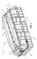
図1~図4Aは、ハウジング14と、ハウジング14内に受け入れられた複数のバッテリセルアセンブリ18とを備えるバッテリパックアセンブリ10を示している。図示の実施形態では、バッテリパックアセンブリ10は2つのバッテリセルアセンブリ18を備える。他の実施形態では、バッテリパックアセンブリ10は、1つ又は複数のバッテリセルアセンブリ18(例えば、3つ、4つなど)を備え得る。バッテリパックアセンブリ10は、様々な原動機付き動力工具(例えば、カットオフソー、マイターソー、テーブルソー、コアドリル、オーガ、破砕機、解体ハンマー、圧縮機、振動器、圧縮器、ドレンクリーナ、溶接機、ケーブルタガー、ポンプなど)、屋外工具(例えば、チェーンソー、ストリングトリマー、ヘッジトリマー、ブロワ、芝刈り機など)、他の原動機付きデバイス(例えば、車両、ユーティリティカート、マテリアルハンドリングカートなど)、及び非原動機付き電気デバイス(例えば、電源、照明、交流/直流アダプタ、発電機、パーソナル電子機器など)(以下、本明細書では、これらのうちのいずれであっても「デバイス」と呼ぶ)に接続可能であり、電力供給するように動作可能である高出力バッテリパック(例えば、少なくとも約80ボルト(V)の公称電圧を有するバッテリパック)となるように構成される。 1-4A illustrate a
ハウジング14は、上面22と、底面26と、第1の側面30と、第1の側面30とは反対側にある第2の側面34と、第1の端部38と、第1の端部38とは反対側にある第2の端部42とを備える。加えて、ハウジング14は、第1の端部38及び第2の端部42を通って延びる縦軸46を備える。ハウジング14の横軸50は、第1の側面30及び第2の側面34を通って延びる。横軸50は縦軸46に直交する。 The
図2~図4を参照すると、ハウジング14は、内部に画定された内部空洞58を更に備える。各バッテリセルアセンブリ18は、内部空洞58内に配置される。加えて、ハウジング14は、内部空洞58がバッテリパックアセンブリ10の外部と流体連通しないように密閉される。 Referring to FIGS. 2-4,
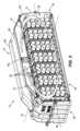
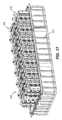
図3~図4Aを参照すると、各バッテリセルアセンブリ18は、複数のバッテリセル62と、複数のコネクタ66と、内部空洞58内で複数のバッテリセル62を支持するハウジング又はフレーム70とを備える。各バッテリセル62は、第1の端部78と第2の端部82との間に延びる本体74を有する。加えて、各本体74は、本体74の対応する第1の側面30及び第2の側面34をそれぞれ通って延びるバッテリセル軸86(図4)に沿って延びる。 Referring to FIGS. 3-4A, each
各バッテリセルアセンブリ18は、バッテリセル62のそれぞれがハウジング14の縦軸46に対して向けられるように内部空洞58内に配置される。図示の実施形態では、対応する各バッテリセル62のバッテリセル軸86は、内部空洞58内で縦軸46に直交して(すなわち、横軸50に平行に)延びる。他の実施形態では、バッテリセル軸86は縦軸46に平行に向けられてもよく、及び/又はバッテリセル軸86のいくつかが同じ方向又は異なる方向に向けられてもよい。加えて、図示の各バッテリセルアセンブリ18は、70個のバッテリセル62を備える。他の実施形態では、バッテリセルアセンブリ18は、2つ以上のバッテリセル62を備え得る。ハウジング14は、各バッテリセルアセンブリ18が所定の数のバッテリセル62の部分を有する状態で、所定の数のバッテリセルアセンブリ18を受け入れるように形状及びサイズを定められる。 Each
各バッテリセル62は、約3V~約5Vの公称電圧を有してもよく、約2Ah~約6Ah(場合によっては、約3Ah~約5Ah)の公称容量を有してもよい。バッテリセル62は、任意の種類の充電式バッテリセル化合物タイプであってよく、例えば、リチウム(Li)、リチウムイオン(Liイオン)、他のリチウム系化合物、ニッケル-カドミウム(NiCd)、ニッケル金属水素化物(NiMH)などであってよい。 Each
図4Aを参照すると、バッテリセル62は、バッテリパックアセンブリ10の所望の電気特性(例えば、公称電圧、電流出力、電流容量、電力容量など)を提供するために、直列、並列、又は直列及び並列の組み合わせで接続され得る。バッテリセル62は、コネクタ66(例えば、バスバー)によって一緒に接続される。各バッテリセル62は、1本又は複数本のワイヤ90によって、コネクタ66のうちの1つに接続される。図示の実施形態では、各バッテリセル62は、対応するバッテリセル62に隣接するコネクタ66に1本のワイヤ90によって接続される。ワイヤ90は、バッテリセル62の第2の端部82に結合される(例えば、溶接などのワイヤボンディングプロセスによって)。各コネクタ66は、少なくとも2つ以上のバッテリセル62に直接結合される。図示の実施形態では、各コネクタ66が、10個のバッテリセル62に直接結合される。 Referring to FIG. 4A,
図示の各コネクタ66は、導電性プレートである。更に、コネクタ66は、バッテリパックアセンブリ10内の他のバッテリセルアセンブリ18及び/又はバッテリパックアセンブリ10のバッテリ端子接点(図示せず)に電気的に接続するように構成される。図5に示すように、2つのバッテリセルアセンブリ18は、ハウジング14の底面26に隣接する各バッテリセルアセンブリ18の端部を圧着ボンディングすることによって電気的に結合される。バッテリパックアセンブリ10のバッテリ端子接点は、デバイスとバッテリパックアセンブリ10との間の電力の伝達を容易にするために、デバイスのデバイス接点と電気的且つ機械的に係合するように構成される。そのため、バッテリセルアセンブリ18のそれぞれが、バッテリパックアセンブリ10内でバッテリ端子接点に電気的に接続され得る。バッテリパックアセンブリ10は、各バッテリパックアセンブリ10が1つ又は複数のバッテリセルアセンブリ18を備え、且つ各バッテリセルアセンブリ18が2つ以上のバッテリセル62を備え得るようにモジュール化されるように構成される。バッテリパックアセンブリ10は、ハウジング14内に配置されたバッテリパックエレクトロニクスを更に備え得る。バッテリパックエレクトロニクスは、とりわけ、プリント回路基板(図5AのPCB94)、1つ又は複数の電気コンポーネント(例えば、CPU、変圧器、FETなど)、及びバッテリ端子接点を含み得る。 Each
図5A及び図5Bのそれぞれは、バッテリパックアセンブリ10’、10’’の別の例を概略的に示している。図1~図4Aに示したバッテリパックアセンブリ10の実施形態と同様の構成要素及び特徴は、同様の参照符号にそれぞれプライム記号(「’」)、二重プライム記号(「’’」)を加えた参照符号を付与されている。したがって、先にバッテリパックアセンブリ10に関して論じたことは、バッテリパックアセンブリ10’、10’’にも同様に適用され、繰り返して記載しない。特に、図5A及び図5Bは、バッテリパックエレクトロニクスのPCB94の場所を示している。PCB94は、バッテリセルアセンブリ18’、18’’に対して配置可能である。一例では、図5Aに示すように、PCB94は、バッテリセルアセンブリ18’のそれぞれの最上縁部とハウジング14’の上面22’との間に配置される。図5Bに示す別の例では、PCB94は、バッテリセルアセンブリ18’’の対向する側面の間に配置される。 5A and 5B each schematically illustrate another example of a battery pack assembly 10', 10''. Components and features similar to the embodiments of
再び図2~図4Aを参照すると、各バッテリセルアセンブリ18のフレーム70は、複数の支持部材102、104と、複数の支持部材102、104を接続する複数の脚部材106とを備える。各支持部材102、104は、第1の縁部114と第1の縁部114とは反対側にある第2の縁部118との間に延びる本体110を有する(図4A)。加えて、本体110は、複数の開口部122を画定する。各開口部122は、内部空洞58内でバッテリセル62のうちの1つと整列するように構成される。そのため、各支持部材102、104は、バッテリセル62の数と同じ数の開口部122を有する。対応するバッテリセル62の各端部78、82は、開口部122のうちの1つに受け入れられる。図示の開口部122は列状に配置され、列のうちのいくつかは、更に後述するように、互いに間隔を空けて配置されて、バッテリセル62の列のいくつかの間に間隙126(図4)を形成する。したがって、支持部材102、104は、内部空洞58内でバッテリセル62の位置を決定し、維持するように構成され得る。バッテリセルアセンブリ18における、間隙126を形成しない残りの空間は密閉され得る。 Referring again to FIGS. 2-4A, the
図示の実施形態では、各バッテリセルアセンブリ18が、バッテリセルの両端部78、82に配置された2つの支持部材102、104を備える。第1の支持部材102が、ハウジング14の内面に隣接して配置される。各バッテリセルアセンブリ18の第1の支持部材102は、ハウジング14の内面に結合される。そのため、フレーム70は、ハウジング14の内部空洞58内でバッテリセル62を少なくとも部分的に支持するように構成される。 In the illustrated embodiment, each
第2の支持部材104が第1の支持部材102とは反対側に配置される。2つのバッテリセルアセンブリ18の各第2の支持部材104は、側面130(図4A)を備える。第2の支持部材104の側面130どうしは、内部空洞58内で互いに対向する関係に配置される。各バッテリセルアセンブリ18のコネクタ66は、第2の支持部材104の対応する側面130に配置される。 A
図4Aを参照すると、フレーム70の脚部材106は、第1の支持部材102と第2の支持部材104との間にそれぞれ延びる。脚部材106のそれぞれが、支持部材102、104の第1の縁部114又は第2の縁部118にそれぞれ配置される。各脚部材106が、対応するバッテリセル62のバッテリセル軸86に平行に延びる。脚部材106は、1つ又は複数のセクション134、136、138によって形成され得る。例えば、図示の実施形態では、各脚部材106が3つのセクション134、136、138によって形成され、第1のセクション134が第1の支持部材102に結合され、第2のセクション136が第2の支持部材104に結合され、中間の第3のセクション138が第1のセクション134と第2のセクション136との間に延びる。更に、脚部材106及び/又はその部分は、支持部材102、104のうちの1つ又は複数と一体であってもよい。或いは、脚部材106は、別体に形成され、支持部材102、104に固定されてもよい。 Referring to FIG. 4A,
図2~図4を参照すると、内部空洞58内でバッテリセルアセンブリ18やバッテリエレクトロニクスが占有しない空間が、1つ又は複数の空気流チャネル142に分割される。空気流チャネル142は、密閉されたハウジング14内で各バッテリセルアセンブリ18を囲むように配置される。図示の実施形態では、バッテリパックアセンブリ10は、ハウジング14の上面22に配置された複数の空気流トンネル150を更に備える。空気流トンネル150は、ハウジング14の内部空洞58と流体連通する。図示のハウジング14は、4つの孔154と2つの空気流トンネル150とを備える。各空気流トンネル150は、孔154のうちの1つを覆うように配置される。残りの2つの孔154は、プレート部材158(図3)によって覆われる。他の実施形態では、図示のバッテリパックアセンブリ10は、4つ以下の空気流トンネル150を備え得る。 2-4, the space within
図2を参照すると、バッテリパックアセンブリ10は、複数のファン162を更に備え得る。各ファン162は、複数のバッテリセルアセンブリ18のうちの1つ又は複数に隣接して配置される。図示の実施形態では、バッテリパックアセンブリ10は2つのファン162を備え、各ファン162が空気流トンネル150のうちの1つの中に配置される。そのため、空気流トンネル150のうちの1つ、いくつか、又はすべてが、ファン162を備える。他の実施形態では、ファン162のうちの1つ、いくつか、又はすべてが、バッテリパックアセンブリ10のハウジング14内に配置可能である。例えば、図5A~図5Bに示すように、バッテリパックアセンブリ10は、ハウジング14の内部空洞58内に配置された2つのファン162を備える。より具体的には、ファン162は、PCB94の両側に、ハウジング14の上面22に近接して配置される。 Referring to FIG. 2,
複数のファン162は、バッテリパックアセンブリ10の密閉されたハウジング14内で空気流を循環させるように動作可能である。より具体的には、空気は、密閉型バッテリパックアセンブリ10の内部空洞58中を循環されるが、バッテリパックアセンブリ10の内部空洞58から抜け出ることはない(又は、抜け出すとしても、少なくとも無視できる量の空気しか抜け出さない)。図示の実施形態では、空気流は、ハウジング14の上面22と底面26との間に導かれる。他の実施形態では、バッテリパックアセンブリ10は、密閉されたハウジング14内で同じ方向又は異なる方向に空気流を循環させるための1つ又は複数のファン162(3つ、4つなど)を備え得る。図23は、ハウジング14内で循環される空気流の一例を示している。 The plurality of
図6~図7は、バッテリパックアセンブリ10’’’の更に別の例を示している。図1~図4Aに示したバッテリパックアセンブリ10の実施形態と同様の構成要素及び特徴は、同様の参照符号に三重プライム記号(「’’’」)を加えた参照符号を付与されている。したがって、先にバッテリパックアセンブリ10に関して論じたことは、バッテリパックアセンブリ10’’’にも同様に適用され、繰り返して記載しない。特に、図6~図7は、複数のファン162’’’の代替的な場所を示している。複数のファン162’’’は、内部空洞58’’’内でバッテリセルアセンブリ18’’’に対して配置可能である。加えて、各ファン162は、ハウジング14’’’の第1の端部38’’’及び第2の端部42’’’のそれぞれに近接して配置される。更に、各ファン162’’’は、ハウジング14’’’の対応する端部38’’’、42’’’とバッテリセルアセンブリ18’’’との間に配置される。1つ又は複数の空気流トンネル150’’’が、図1~図4Aに示す空気流トンネル150’’’と同様に、ハウジング14’’’内の空気流を導くために、ファン162’’’ごとに(図1~図4Aに示す上面22ではなく)バッテリパックアセンブリ10’’’のハウジング14’’’の第1の端部38’’’及び第2の端部42’’’に近接して設けられ得る。図示の実施形態では、空気流は、ハウジング14’’’の第1の側面30’’’と第2の側面34’’’との間に導かれる。より具体的には、空気流は、複数のバッテリセル62’’’を通る電圧が上昇する方向に導かれ得る。 6-7 illustrate yet another example of a battery pack assembly 10'''. Components and features that are similar to the embodiments of
図8~図13を参照すると、他の実施形態では、空気流トンネル150のうちの1つ若しくは複数及び/又はハウジング14は、内部に複数のデフレクタ170A、170B、170Cを備えて、空気の一部が1つ又は複数のファン162によってバッテリセルアセンブリ18の周囲に導かれ、空気の一部がバッテリセルアセンブリ18の隣接するバッテリセル列の間の間隙126を通して導かれ得るようにし得る。 8-13, in other embodiments, one or more of the
デフレクタ170A、170B、170Cは、バッテリパックアセンブリ10のハウジング14、バッテリセルアセンブリ18のうちの1つ若しくは複数のフレーム70、又はそれらの組み合わせに結合され得る。デフレクタ170A、170B、170Cは、ハウジング14/フレーム70と一体化されても、又は別体に形成されてもよい。デフレクタ170A、170B、170Cのうちの1つ又は複数が、互いに流体連通してもよい。
図8~図9は、2つのデフレクタ170Aを互いに隣接して配置させた一例を示している。各デフレクタ170Aは、バッテリセル62の列の一端に配置され、バッテリセル62の列のうちの2つの列の間にある対応する間隙126を通って延びる。各デフレクタ170Aは、端部部分174と、端部部分174に流体接続された複数の案内部材178とを備える。図示のデフレクタ170Aは2つの案内部材178を備え、各案内部材178が間隙126のうちの1つを通って延びる。更に、端部部分174は、対応するデフレクタ170Aを通して空気流を導くためのファン162(図9)のうちの1つに隣接して配置可能である。いくつかの実施形態では、端部部分174は、ファン162のうちの1つを少なくとも部分的に受け入れる、又はファン162のうちの1つに隣接して配置されるように構成され得る。 8 and 9 show an example in which two
別の例では、図10~図11を参照すると、デフレクタ170Bは、バッテリセル62の列の一端に配置され、バッテリセル62の第1の端部78及び第2の端部82のうちの一方のそばを通り過ぎて延び得る。上記と同様に、デフレクタ170Bは、端部部分174と、端部部分174に流体接続された複数の案内部材178とを備える。図8~図9に示すように隣接するバッテリ列の間の間隙126を通って延びるのではなく、各案内部材178は、バッテリセル62の第1の端部78及び第2の端部82のうちの一方のそばを通り過ぎて延びる。端部部分174は、対応するデフレクタ170Bを通して空気流を導くためのファン162(図11)のうちの1つに隣接して配置可能である。更に、図示の例では、第1のデフレクタ170Bの案内部材178のうちの1つが、第2のデフレクタ170Bの隣接する案内部材178と流体連通する。したがって、複数のファン162が、組み合わされた空気流を2つ以上のデフレクタ170Bを通して導くように構成され得る。 In another example, referring to FIGS. 10-11, the
図12A~図12Cは、デフレクタ170Bを通して空気流を導くことの複数の例を示している。図12Aは、単一のファン162を有する一例を示しており、単一のファン162によって、空気流が第1の方向に第1のデフレクタ170Bを通り、その後、空気流は第1の方向とは反対の第2の方向に第2のデフレクタ170Bを通して導かれる。図12Bは、2つのファン162を有する別の例を示しており、各ファン162によって、対応するデフレクタ170Bを空気流が通る。図12Cは、これもまた2つのファン162を有する更に別の例を示しており、空気流が接続されたデフレクタ170Bを通して往復する流れで導かれ得る。 12A-12C illustrate multiple examples of directing airflow through
図13は、互いに隣接して配置された4つのデフレクタ170Cを備える更にまた別の例を示しており、各デフレクタ170Cが、端部部分174と2つの案内部材178とを有する。上で論じた各例と同様に、案内部材178は、バッテリセル62の第1の端部78及び第2の端部82のうちの一方のそばを通り過ぎて延びる。いくつかの実施形態では、ファン162が、対応するデフレクタ170Cのそれぞれの端部部分174に隣接して配置可能であり得る。他の実施形態では、端部部分174のいくつかのみが対応するファン162に隣接し、残りのデフレクタ170Cは、空気流をファン162から受け入れるデフレクタ170Cに流体連通する。更に他の実施形態では、案内部材178のいくつかは、バッテリセル62の第1の端部78及び第2の端部82のうちの1つのそばを通り過ぎて延びるように配置されてもよく、残りの案内部材178は、バッテリセル62の隣接する列の間の間隙126を通って延び得る。 FIG. 13 shows yet another example with four
他の実施形態では、空気流トンネル150及びデフレクタ170A、170B、170Cの構成では、バッテリセル62は、ハウジング14又はその部分を密閉するための熱伝導性ギャップフィラー、接着剤、ポッティング、又は/及び封止剤によって、空気流トンネル150、デフレクタ170A、170B、170C、及び/又は端部部分174に熱的に結合され得る。PCB94、電源配線、及びバッテリセル62は、ハウジング14の密閉された部分に配置される。密閉されたハウジング14又はその部分において、空気流トンネル150、デフレクタ170A~C、及び/又は端部部分174は、熱伝導性ギャップフィラー、接着剤、ポッティング、又は/及び封止材を介してバッテリセル62に熱的に結合される。したがって、ファン162は、密閉型バッテリパックアセンブリ10又はその部分の外側からの空気を空気流トンネル150を通して導くように構成される。 In other embodiments, in the
図14~図16は、バッテリパックアセンブリ210の部分の更にまた別の例を示している。図1~図4Aに示したバッテリパックアセンブリ10の実施形態と同様の構成要素及び特徴は、同様の参照符号に「200」を加えた参照符号を付与されている。したがって、先にバッテリパックアセンブリ10に関して論じたことは、バッテリパックアセンブリ210にも同様に適用され、繰り返して記載しない。特に、図14~図16は、バッテリパックアセンブリ210の空気流トンネル350及び複数のファン362の代替的な構成を示している。空気流トンネル350は、バッテリセルアセンブリ218の一方の側に配置され、ファン362は、反対側にある他方の側に配置される。空気流トンネル350のそれぞれが、空気流を受け入れ、空気流をバッテリパックアセンブリ210のバッテリセル262に向かって戻るように案内するための曲線形状を有する。ファン362は、バッテリセルアセンブリ218を通して、空気流トンネル350に向かって空気流を導くように向けられる。クロスフロー空気流が、バッテリパックアセンブリ210のハウジング214内に形成される。換言すれば、各ファン362は、対応するバッテリセルアセンブリ218で第1の方向に空気を流すように構成される。その後、空気流は、第1の方向とは反対の第2の方向に対応するバッテリセルアセンブリ218を流れるように対応する空気流トンネル350によって再び導かれる。 14-16 illustrate yet another example of a portion of battery pack assembly 210. FIG. Components and features that are similar to the embodiments of
更に、図16を参照すると、(図4のように隣接する列のうちのいくつかの間に間隙126が設けられるのではなく)各バッテリセル列が互いに等距離に配置される。バッテリセル262のそれぞれがスリーブ部材382に配置される。リブ386がスリーブ部材382の間に延び、スリーブ部材382を結合する。より具体的には、列状のバッテリセルのそれぞれがリブ386によって結合される。他の実施形態では、バッテリセルアセンブリ218のバッテリセル362のすべてがリブ386によって接続される。スリーブ部材382及びリブ386は、ある材料によって形成される。図示の実施形態では、材料はプラスチックである。 Further, referring to FIG. 16, each row of battery cells is placed equidistant from each other (rather than having
バッテリセル262は、バッテリセル262を外部環境から密閉するために金属又はプラスチックスリーブ382に配置される。この構成では、ハウジング14又はハウジング14のうちのバッテリセル262を囲む部分が、ファン362がバッテリパックアセンブリ310の外部からの空気を用いて換気し得るように密閉されなくてもよい。加えて、空気流トンネル350及び電源配線(例えば、バスバー、セルヘッダなど)もまた、フレーム270の空気流トンネルに密閉されるが熱的に結合され得る。このことは、外部環境から流入する空気によるバッテリセル262の破損を抑制又は防止し得る。
他の実施形態では、バッテリセル262は、金属又はプラスチックスリーブにはなく、図1~図4Aに開示されるように、密閉されたハウジング14に配置される。そして、クロスフローファン362は、図1~図4Aの密閉されたハウジング14の内部で空気を循環させるように構成される。 In other embodiments, the
図17~図18は、バッテリパックアセンブリ410の部分の更にまた別の例を示している。図1~図4Aに示したバッテリパックアセンブリ10の実施形態と同様の構成要素及び特徴は、同様の参照符号に「400」を加えた参照符号を付与されている。したがって、先にバッテリパックアセンブリ10に関して論じたことは、バッテリパックアセンブリ410にも同様に適用され、繰り返して記載しない。特に、図17~図18は、ハウジング414の内面416と結合される空気流トンネル550の代替的な構成を示している(図18)。図示の空気流トンネル550は、ハウジング414の上面422と一体化され、空気流チャネル542のうちの1つ又は複数を少なくとも部分的に画定するバッフルである。空気流トンネル550は曲面を有する。空気流トンネル550は、内部空洞458内に配置される。バッテリパックアセンブリ410は、ハウジング414の空気流トンネル550とは反対側の側面(例えば、底面426)に配置される、図1~図4Aの空気流トンネル150と同様の追加の空気流トンネル(図示せず)を更に備え得る。更に、1つ又は複数のファン(例えば、図1~図4Aのファン162)が、内部空洞458及び/又は追加の空気流トンネルのうちの1つ若しくは複数に配置され得る。 17-18 illustrate yet another example of a portion of
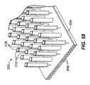
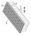
図19~図22は、複数のバッテリセルアセンブリ618を備えるバッテリパックアセンブリ610の別の例を示している。図1~図4Aに示したバッテリパックアセンブリ10の実施形態と同様の構成要素及び特徴は、同様の参照符号に「600」を加えた参照符号を付与されている。したがって、先にバッテリパックアセンブリ10に関して論じたことは、バッテリパックアセンブリ610にも同様に適用され、繰り返して記載しない。特に、ここでは、ハウジング及びフレームにおける違いについて論じる。 19-22 illustrate another example of a
各バッテリセルアセンブリ618は、複数のバッテリセル662と、複数のコネクタ666と、複数のバッテリセル662を支持するハウジング又はフレーム670とを備える。フレーム670は、ベース部分672と、ベース部分672に結合されたカバー部分676とを備える。ベース部分672とカバー部分676とは、バッテリパックアセンブリ610の内部空洞658の部分を協働して画定する。内部空洞658の部分は、複数のセクション680に分割される。 Each
図示の実施形態では、ベース部分672は、複数の外壁684、685、687と、複数の内壁688とを備える(図21)。複数の外壁684、685、687は、バッテリセルアセンブリ618の第1の縁部714及び第2の縁部718をそれぞれ画定する第1の外壁及び第2の外壁684を含む。複数の外壁684、685、687は、側壁685と、第1の端壁及び第2の端壁687とを更に含む。複数の内壁688は、第1の外壁及び第2の外壁684の間に延びる。内壁688はまた、側壁685からカバー部分676に向かって延びる。内壁688は、内部空洞658を複数のセクション680に分割する。 In the illustrated embodiment,
ベース部分672は、側壁685からカバー部分676に向かって延びる複数の突起692を更に備える。突起692は、複数のセクション680のそれぞれに配置可能である。加えて、突起692は、内部空洞658内で複数のバッテリセル662の間に配置可能である。図示の各突起692は、略菱形の断面形状を有する。他の実施形態では、突起692は、矩形、円形などの他の断面形状を有していてもよく、突起692のうちのいくつか又はすべてが同じ形状を有しても、又は異なる形状を有してもよい。突起692のそれぞれが、バッテリセル662のそれぞれに平行に延びる。
カバー部分676は、本体696と、本体696によって画定される複数の開口部722とを備える。各開口部722は、内部空洞658内でバッテリセル662のうちの1つと整列するように構成される。そのため、カバー部分676は、バッテリセル662の数と同じ数の開口部722を有する。バッテリセル662のそれぞれの第1の端部678は、開口部722のうちの対応する1つの開口部に受け入れられる。加えて、本体696は表面698を有し、コネクタ666は表面698によって支持される。
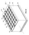
図19及び図20を特に参照すると、バッテリパックアセンブリ10は2つのバッテリセルアセンブリ618を備える。バッテリセルアセンブリ618は、カバー部分676が互いに対向する関係にあるように配置される。バッテリセルアセンブリ618は、カバー部分676が所定の距離Aだけ間隔を空けるように配置され得る。所定の距離Aは、バッテリセルアセンブリ618の間に空間699を形成するように選択される。 With particular reference to FIGS. 19 and 20,
各バッテリセルアセンブリ618は、(図1~図4Aのバッテリパックアセンブリ10に開示されているように、ハウジングに配置されるのではなく)バッテリパックアセンブリ610のハウジング614の部分を形成する。より具体的には、各バッテリセルアセンブリ618のベース部分672は、ハウジング614の1つ又は複数の面を画定する。図示の実施形態では、各バッテリセルアセンブリ618が、バッテリパックアセンブリ610の2分の1を形成する。加えて、空間699が密閉されて、バッテリセルアセンブリ618の間に密閉領域が形成される。空間699は、エレクトロニクス(例えば、PCB694、バッテリセル662を接続するコネクタ666など)を受け入れるように構成される。したがって、バッテリセルアセンブリ618及びその間にある密閉された間隙699によって、密閉された筐体が形成される。 Each
PCB694は、バッテリセルアセンブリ618に対して配置可能である。一例では、図20に示すように、PCB694は、空間699に、バッテリセルアセンブリ618のそれぞれの第1の縁部714に近接して配置される。本実施形態では、PCB694は、バッテリセルアセンブリ618に対して横に延びる。図19に示すような別の例では、PCB694は、空間699でバッテリセルアセンブリ618のカバー部分676の間に配置され、カバー部分676の表面に平行に延びる。
図24及び図25は、バッテリセルアセンブリ18のためのバッテリセル62の代替的な構成を概略的に示している。バッテリセル62のそれぞれが等間隔に配置される。図24に示すように、隣接する列のそれぞれが、バッテリセル62が縦方向(縦軸46に平行)、鉛直方向、及び横方向(横軸50に平行)のうちの1つ又は複数で整列されるように整列される。対照的に、図25に示すように、隣接する列のそれぞれが、バッテリセル62が互いにオフセットされるように千鳥状に配置される。このことは、ハウジング14を通る空気流の方向に影響を与え得る。 24 and 25 schematically illustrate alternative configurations of
図26~図28は、バッテリパックアセンブリ810の別の例を示している。図1~図4Aに示したバッテリパックアセンブリ10の実施形態と同様の構成要素及び特徴は、同様の参照符号に「800」を加えた参照符号を付与されている。したがって、先にバッテリパックアセンブリ10に関して論じたことは、バッテリパックアセンブリ810にも同様に適用され、繰り返して記載しない。特に、図26~図28は、図25に示すバッテリセル862の列の千鳥状の配置を示している。加えて、図26~図28は、ファン962の代替的な位置を示しており、ファン962は、ハウジング814内で一方の端部(第2の端部842)及び上面822に近接する。更に、図26~図28は、それぞれがハウジング814を通る流路に沿って空気流を導くための曲線形状を有する空気流トンネル950(すなわち、バッフル)の代替的な構成を示している。加えて、空気流トンネル950は、ハウジング814内の各端部838、842に近接して配置される。ファン962は、空気流をバッテリセルアセンブリ818を通して導くために、一方の端部842に近接した空気流トンネル950に向かって空気流を導くように向けられる。空気流トンネル950は、ハウジング814に結合され得る、又は他の仕方で一体化され得る。空気流トンネル950は、内部空洞858内に配置される。 26-28 illustrate another example of a
図28を特に参照すると、ハウジング814は、バッテリセル862の外周に配置されたねじボス928を備え得る。PCB894は、バッテリセルアセンブリ818のそれぞれの最上縁部とハウジング814の上面822との間に配置される。ファン962は、PCB894の縁部とハウジング814の端部842との間に配置される。 With particular reference to FIG. 28, the
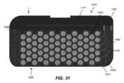
図29~図32は、バッテリパックアセンブリ1010の別の例を示している。図1~図4Aに示したバッテリパックアセンブリ10の実施形態と同様の構成要素及び特徴は、同様の参照符号に「1000」を加えた参照符号を付与されている。したがって、先にバッテリパックアセンブリ10に関して論じたことは、バッテリパックアセンブリ1010にも同様に適用され、繰り返して記載しない。図26~図28の実施形態と同様に、図29~図32の実施形態もまた、図25に示すようなバッテリセル1062の列の千鳥状の配置と、ハウジング1014内で一方の端部(第2の端部1042)及び上面1022に近接するファン1162の代替的な配置と、空気流トンネル1150(すなわち、バッフル)とを示している。ファン1162は、空気流をバッテリセルアセンブリ1018を通して導くために、一方の端部1042に近接した空気流トンネル1150に向かって空気流を導くように向けられる。空気流トンネル1150は、ハウジング1014に結合され得る、又は他の仕方で一体化され得る。空気流トンネル1150は、内部空洞1058内に配置される。更に、PCB1194(図31)は、バッテリセルアセンブリ1018のそれぞれの最上縁部とハウジング1014の上面1022との間に配置される。ファン1162(そのうちの1つだけ示す)は、PCB1094の縁部とハウジング1014の端部1042との間に配置される。 29-32 illustrate another example of a
バッテリパックアセンブリ1010は、複数のポート1152、1156を更に備える。図示の実施形態では、バッテリパックアセンブリ1010は、第1の複数のポート1152と第2の複数のポート1156とを備える。ポート1152、1156のそれぞれがハウジング1014によって画定される。第1の複数のポート1152は静圧ポートであり、第2の複数のポート1156は動ポートである。ファン1162は、ハウジング1014内で第2の複数のポート1156から間隔を空けて配置される。ポート1152、1156のそれぞれが、バッテリパックアセンブリ1010の外部と内部空洞1058を選択的に流体連通させるように調節可能である。
図32は、定常状態の空気流を通して、空気の乱流エネルギーの強さを空間的に示している。 FIG. 32 spatially illustrates the strength of air turbulence energy through steady-state airflow.
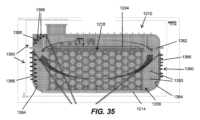
図33~図36は、バッテリパックアセンブリ1210の別の例を示している。図1~図4Aに示したバッテリパックアセンブリ10の実施形態と同様の構成要素及び特徴は、同様の参照符号に「1200」を加えた参照符号を付与されている。したがって、先にバッテリパックアセンブリ10に関して論じたことは、バッテリパックアセンブリ1210にも同様に適用され、繰り返して記載しない。図26~図28の実施形態及び図29~図32の実施形態と同様に、図33~図36の実施形態もまた、図25に示すようなバッテリセル1262の列の千鳥状の配置と、ハウジング1214内で一方の端部(第2の端部1242)及び上面1222に近接するファン1362の代替的な配置と、空気流トンネル1350(すなわち、バッフル)とを示している。バッテリパックアセンブリ1210は、ハウジング1214内に追加の空気流案内部材1353を備え、バッテリセルアセンブリ1218の端部とハウジング1214の対応する端部1238、1242との間に配置され得る。バッフル1350は、案内部材1353に配置され得る。更に、図26~28の実施形態及び図29~32の実施形態と同様に、図33~36の実施形態は、PCB1394(図34)が、バッテリセルアセンブリ1218のそれぞれの最上縁部とハウジング1214の上面1222との間に配置されることを更に示している。ファン1362(そのうちの1つだけ示す)は、PCB1294の縁部とハウジング1214の端部1242との間に配置される。 33-36 illustrate another example of a
バッテリパックアセンブリ1210は、ハウジング1214の内部に結合されるか、又は他の仕方で一体化される複数のヒートシンク1360(図35~図36)を更に備える。図示の実施形態では、ハウジング1214の壁のうちの1つ又は複数の内面1364が、ヒートシンク1360を備える。図示のヒートシンク1360のそれぞれが、そこから延びる複数のフィン1368を有するプレート部材1366を備える。加えて、図示のヒートシンク1360のそれぞれが、インサート成形されたアルミニウムのスタンピングによって作られる。ヒートシンク1360のそれぞれが、内部空洞1258からハウジング1214へ熱を熱伝導するように構成される。
図37~図39は、バッテリパックアセンブリ1410の別の例を示している。図1~図4Aに示したバッテリパックアセンブリ10の実施形態と同様の構成要素及び特徴は、同様の参照符号に「1400」を加えた参照符号を付与されている。したがって、先にバッテリパックアセンブリ10に関して論じたことは、バッテリパックアセンブリ1410にも同様に適用され、繰り返して記載しない。図37~図39の実施形態は、対応する各バッテリセル1462のバッテリセル軸1486が、内部空洞1458内で縦軸1446に直交し、且つ横軸1450に直交して延びるようにハウジング1414内に配置されたバッテリセルアセンブリ1418のそれぞれを示している。換言すれば、バッテリセル1462は、ハウジング1414内で鉛直方向に延びる。 37-39 illustrate another example of a
図40は、図26~図28のバッテリパックアセンブリ810の別の例を示している。図26~図28に示したバッテリパックアセンブリ810の実施形態と同様の構成要素及び特徴は、同様の参照符号に「A」を加えた参照符号を付与されている。したがって、先にバッテリパックアセンブリ810に関して論じたことは、バッテリパックアセンブリ810Aにも同様に適用され、繰り返して記載しない。図40の実施形態は、バッテリセル862Aに対して中間又は中央にあるファン962Aの代替的な位置を示している。加えて、バッフル950は、バッテリセル862Aの間の中央に配置されて、ファン962Aからの空気流を、ハウジング814内の両側に配置された2つの別個のバッテリセルアセンブリ818Aに向かって反対方向に分割する。 FIG. 40 shows another example of the
バッテリパックアセンブリ10、210、410、610、810、1010、1210、1410のそれぞれが密閉された筐体であり、バッテリセル62、262、462、662、862、1062、1262、1462によって発生された熱が、バッテリパックアセンブリ10、210、410、610、810、1010、1210、1410の内部空洞58、258、458、658、858、1058、1258、1458内からハウジング14、214、414、614、814、1014、1214、1414に伝達されるように構成される。いくつかの実施形態では、ハウジング14、214、414、614、814、1014、1214、1414はプラスチックで作られ、熱はプラスチックハウジング14、214、414、614、814、1014、1214、1414に伝達される。 Each of the
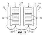
図41を参照すると、密閉型バッテリパックアセンブリ10、210、410、610、810、1010、1210、1410は、システム192に配置され得る。システム192は密閉されても、又は密閉されなくてもよい。システム192のファン196は、ハウジング14、214、414、614、814、1014、1214、1414からの熱をハウジング14、214、414、614、814、1014、1214、1414の外部に伝達するため、密閉型バッテリパックアセンブリ10、210、410、610、810、1010、1210、1410(例えば、側面及び上面)にわたって空気流を導くために、密閉型バッテリパックアセンブリ10、210、410、610、810、1010、1210、1410の外部に配置され得る。 Referring to FIG. 41, sealed
更に、図9、図16、図18、及び図22を参照すると、バッテリパックアセンブリ10、10’、10’’、10’’’、210、410、610は、バッテリセルアセンブリ18の組み立て中などに流体190を受け入れるように構成される。流体190は、ギャップフィラー、ポッティング、封止剤などの接着特性を有する熱伝導性材料、又は熱伝導性である接着材料(例えば、接着剤)を含む。図示の実施形態では、流体190は熱伝導性シリコーンである。図9及び図18を参照すると、バッテリセルアセンブリ18、418の各バッテリセル列が、流体190を受け入れるように構成される(1列のみが流体190を受け入れるように示されている)。流体190は、対応するバッテリセル62、462によって占有されていない、バッテリセルアセンブリ18、418のバッテリセル列によって画定された空間を満たすように構成される。列は、バッテリセルアセンブリ18、418内に設けられた間隙126、526によって分離される。図16を参照すると、流体190は、対応するバッテリセル262の各スリーブ部材382に受け入れられるように構成される。そのため、流体190は、バッテリセル262と対応するスリーブ部材382の内面との間に配置される。図22を参照すると、流体190は、内部空洞658のセクション680のうちの1つ又は複数に受け入れられるように構成される。より具体的には、流体190は、フレーム670のベース部分672の隣接する内壁688の間に配置されるように構成される。 Further, with reference to FIGS. 9, 16, 18, and 22,
流体190は、バッテリセル列内でバッテリセル62、262、462、662のそれぞれに接触するように配置される。硬化後、接着材料は、バッテリセル62、262、462、662から離れる熱伝達を促進するように構成される。特に、図示の実施形態のいくつかでは、接着材料は、バッテリセル62、262、462、662によって生成された熱を、間隙126、526並びに/又はバッテリセル62、262、462、662の第1の端部78及び第2の端部82に向かって導くように配置される。そのため、主な放熱は、対応するバッテリセル62、262、462、662のバッテリセル軸86に沿った軸方向である。
動作中、複数のファン162、362、962、1162、1362によって生成される空気流と接着材料190との一方又は組み合わせは、バッテリセル62、262、462、662、862、1062、1262、1462から離れる熱の伝達を促進するように構成される。より具体的には、バッテリパックアセンブリ10が放電されているとき、バッテリセル62、262、462、662、862、1062、1262、1462によって発生された熱は、(いくつかの実施形態に関して)接着材料190を介して、空気流チャネル142と、いくつかの実施形態では、空気流チャネル142と流体連通するハウジング14の内部空洞58、58’、58’’、58’’’、258、458、658、858、1058、1258における隣接する列のいくつかの間の間隙126、526とに向かって導かれる。したがって、接着材料190は、バッテリセルアセンブリ18、18’、18’’、18’’’、218、418、618内の熱の熱伝導を促進する。バッテリセルアセンブリ18、18’、18’’、18’’’、218、418、618は、ハウジング14、14’、14’’、14’’’、214、414に配置されて、接着材料190から、空気流チャネル142及び/又は間隙126、526を流れ、複数のファン162によって生じた空気流への熱伝達を促進する。更に、ハウジング14、214、414、614、814、1014、1214、1414内にある、又はこれに他の仕方で一体化された空気流トンネル/バッフル150、350、550、950、1150、1350は、バッテリセルアセンブリ18、218、418、618、818、1018、1218、1418を通して空気流を導くように更に構成される。 During operation, the airflow generated by the plurality of
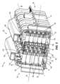
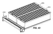
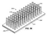
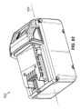
図42は、ハウジング2014の部分と、ハウジング2014の部分内に受け入れられた複数のバッテリセルアセンブリ2018とを含む、バッテリパックアセンブリ2010の部分を示している。図示の実施形態では、バッテリパックアセンブリ2010は4つのバッテリセルアセンブリ2018を備える。他の実施形態では、バッテリパックアセンブリ2010は、1つ又は複数のバッテリセルアセンブリ2018(例えば、2つ、3つなど)を備え得る。バッテリパックアセンブリ2010は、様々な原動機付き動力工具(例えば、カットオフソー、マイターソー、テーブルソー、コアドリル、オーガ、破砕機、解体ハンマー、圧縮機、振動器、圧縮器、ドレンクリーナ、溶接機、ケーブルタガー、ポンプなど)、屋外工具(例えば、チェーンソー、ストリングトリマー、ヘッジトリマー、ブロワ、芝刈り機など)、他の原動機付きデバイス(例えば、車両、ユーティリティカート、マテリアルハンドリングカートなど)、及び非原動機付き電気デバイス(例えば、電源、照明、交流/直流アダプタ、発電機など)(以下、本明細書では、これらのうちのいずれであっても「デバイス」と呼ぶ)に接続可能であり、電力供給するように動作可能である高出力バッテリパック(例えば、少なくとも約2080ボルト(V)の公称電圧を有するバッテリパック)となるように構成される。 FIG. 42 shows a portion of a
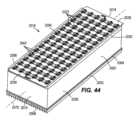
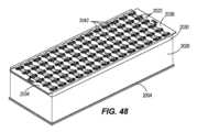
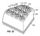
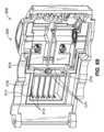
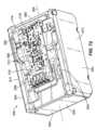
図44~図47を参照すると、各バッテリセルアセンブリ2018は、複数のバッテリセル2022と、ハウジング又はフレーム2026と、フレーム2026に結合されたカバー2030と、複数のコネクタ2034、2038、2042と、ヒートシンク2050とを備える。バッテリセルアセンブリ2018は、前面2054と、後面2058と、第1の側面2062と、第1の側面2062とは反対側にある第2の側面2066と、第1の端部2070と、第1の端部2070とは反対側にある第2の端部2074とを備える。図示の実施形態では、複数のコネクタ2034、2038、2042が前面2054に配置され、ヒートシンク2050が後面2058に配置される。加えて、バッテリセルアセンブリ2018は、第1の端部2070及び第2の端部2074を通って延びる縦軸2078を備える。 44-47, each
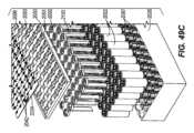
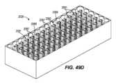
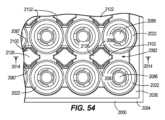
図49を参照すると、フレーム2026及びカバー2030は、バッテリセル2022のうちの1つ又は複数が受け入れられるバッテリセルアセンブリ2018の内部空洞2082を協働して画定する。各バッテリセル2022は、内部空洞2082内で縦軸2078に直交して延びる。図示の実施形態では、バッテリセルアセンブリ2018は、84個のバッテリセル2022を備える。他の実施形態では、バッテリセルアセンブリ2018は、2つ以上のバッテリセル2022を備え得る。例えば、図62に示すように、バッテリセルアセンブリ2018’は、30個のバッテリセル2022を備える。フレーム2026及びカバー2030は、所定の数のバッテリセル2022を受け入れるように形状及びサイズを定められる。カバー2030は、バッテリセル2022のそれぞれの第1の端部2086に隣接して配置される。フレーム2026及びカバー2030は、バッテリセル2022を支持するように構成される。 Referring to FIG. 49,
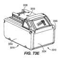
図49B及び図49D~図50を参照すると、バッテリセルアセンブリ2018のフレーム2026は、複数の支持部材2087を備える。各支持部材2087が、フレーム2026の底面2088に結合され、そこから延びる(図49E)。図示の実施形態では、支持部材2087はフレーム2026と一体化される。或いは、支持部材2087は、別体に形成され、フレーム2026に固定され得る。各支持部材2087は、内部空洞2082内に配置される。加えて、各支持部材2087は、内部空洞2082内で複数のバッテリセル2022のうちの隣接する2つのバッテリセル2022の間に配置されるように構成される。更に、互いに対向する支持部材2087のうちの2つが、詳しく後述するように、内部空洞2082内で、ヒートシンク2050の部分を受け入れるための空間2089を協働して画定する。そのため、各支持部材2087が、支持部材アセンブリ2091の一対のうちの一方を形成する。図50に示すように、各空間2089は、フレーム2026の下面を通って延びる孔2089Aに接続される。 49B and 49D-50,
図49Cを特に参照すると、カバー2030は、本体2092と、本体2092によって画定される複数の開口部2093とを備える。各開口部2093は、内部空洞2082内でバッテリセル2022のうちの1つと整列するように構成される。そのため、カバー2030は、バッテリセル2022の数と同じ数の開口部2093を有する。バッテリセル2022のそれぞれの第1の端部2086は、開口部2093のうちの対応する1つの開口部に受け入れられる。加えて、本体2092は表面2096を有し、コネクタ2034、2038、2042は表面2096によって支持される。したがって、カバー2030は、内部空洞2082内でバッテリセル2022の位置を決定し、維持するように構成され得る。 With particular reference to FIG. 49C,
フレーム及びカバーはそれぞれ、ある材料によって形成される。材料は、プラスチック(例えば、ナイロン、ポリカーボネート、ABSなど)であってもよい。いくつかの実施形態では、材料は、金属(例えば、アルミニウム)などの熱伝導性材料であってもよい。 The frame and cover are each formed from a certain material. The material may be plastic (eg, nylon, polycarbonate, ABS, etc.). In some embodiments, the material may be a thermally conductive material such as metal (eg, aluminum).
各バッテリセル2022は、約3V~約5Vの公称電圧を有してもよく、約2Ah~約6Ah(場合によっては、約3Ah~約5Ah)の公称容量を有してもよい。バッテリセル2022は、任意の種類の充電式バッテリセル化合物タイプであってよく、例えば、リチウム(Li)、リチウムイオン(Liイオン)、他のリチウム系化合物、ニッケル-カドミウム(NiCd)、ニッケル金属水素化物(NiMH)などであってよい。 Each
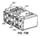
図46を参照すると、バッテリセル2022は、バッテリパックアセンブリ2010の所望の電気特性(例えば、公称電圧、電流出力、電流容量、電力容量など)を提供するために、直列、並列、又は直列及び並列の組み合わせで接続され得る。バッテリセル2022は、コネクタ2034、2038、2042(例えば、バスバー)によって一緒に接続される。コネクタ2034、2038、2042は、第1のコネクタ2034、第2のコネクタ2038、及び1つ又は複数の中間コネクタ2042を含む。各バッテリセル2022は、1本又は複数本のワイヤ2090によって、コネクタ2034、2038、2042のうちの2つに接続される。図示の実施形態では、各バッテリセル2022は、対応するバッテリセル2022に隣接する各コネクタ2034、2038、2042に3本のワイヤ2090によって接続される。ワイヤ2090は、バッテリセル2022の第1の端部2086に結合される(例えば、溶接などのワイヤボンディングプロセスによって)。各コネクタ2034、2038、2042は、少なくとも2つ以上のバッテリセル2022に直接結合される。図示の実施形態では、各コネクタ2034、2038、2042が、12個のバッテリセル2022に直接結合される。 Referring to FIG. 46,
図44及び図49Cに示すように、コネクタ2034、2038、2042は、バッテリセルアセンブリ2018の前面2054に配置される。加えて、図示のコネクタ2034、2038、2042は、カバー2030に結合される。第1のコネクタ2034は、バッテリセルアセンブリ2018の第1の端部2070に配置される。第2のコネクタ2038は、バッテリセルアセンブリ2018の第2の端部2074に配置される。中間コネクタ2042のそれぞれが、縦軸2078に関して、第1のコネクタ2034と第2のコネクタ2038との間に配置される。図示の各コネクタ2034、2038、2042は、導電性プレートである。更に、第1のコネクタ2034及び第2のコネクタ2038のそれぞれが、バッテリパックアセンブリ2010内で他のバッテリセルアセンブリ2018及び/又はバッテリパックアセンブリ2010のバッテリ端子接点(図示せず)に電気的に接続するように構成された電気接点としてそれぞれ構成される。第1のコネクタ2034は正の電気接点として構成され、第2のコネクタ2038は負の電気接点として構成される。 As shown in FIGS. 44 and 49C,
バッテリパックアセンブリ2010のバッテリ端子接点は、デバイスとバッテリパックアセンブリ2010との間の電力の伝達を容易にするために、デバイスのデバイス接点と電気的且つ機械的に係合するように構成される。そのため、バッテリセルアセンブリ2018のそれぞれが、バッテリパックアセンブリ2010内でバッテリ端子接点に電気的に接続され得る。バッテリパックアセンブリ2010は、各バッテリパックアセンブリ2010が1つ又は複数のバッテリセルアセンブリ2018を備え、且つ各バッテリセルアセンブリ2018が2つ以上のバッテリセル2022を備え得るようにモジュール化されるように構成される。バッテリパックアセンブリ2010は、ハウジング2014内に配置されたバッテリパックエレクトロニクス(図示せず)を更に備え得る。バッテリパックエレクトロニクスは、とりわけ、プリント回路基板(PCB)、1つ又は複数の電気コンポーネント(例えば、CPU、変圧器、FETなど)、及びバッテリ端子接点を含み得る。 The battery terminal contacts of
図54~図59を参照すると、各バッテリセルアセンブリ2018のヒートシンク2050は、本体2094と、複数のフィン2098と、フィン2098とは反対側にある複数の突起2102とを備える。本体2094は、バッテリセルアセンブリ2018の後面2058に隣接して配置される。本体2094は、第1の面2106と、第1の面2106とは反対側にある第2の面2110とを備える(図46及び図57)。第1の面2106は、そこから外側に延びる複数のフィン2098を備える。そのため、フィン2098は、バッテリセルアセンブリ2018の内部空洞2082の外側に配置される。本体は熱伝導性材料によって形成される。材料は、アルミニウム、銅などの金属であってもよい。 54-59, the
本体2094の第2の面2110は、内部空洞2082を部分的に画定する。より具体的には、本体2094は、バッテリセルアセンブリ2018の後面2058を覆う。第2の面2110は、そこから延びる複数の突起2102を備える。ヒートシンク2050がフレーム2026に結合されると、突起2102が本体2094から内部空洞2082内に延びる。突起2102は、内部空洞2082内で複数のバッテリセル2022の間に配置可能である。特に、図54に示すように、各突起2102の部分が、複数のバッテリセル2022のうちの隣接する2つのバッテリセル2022の間に配置される。そのため、各突起2102が、バッテリセル2022のうちの4つに隣接して配置される。
図示の各突起2102は、略菱形の断面形状を有する。他の実施形態では、突起2102は、矩形、円形などの他の断面形状を有していてもよく、突起2102のうちのいくつか又はすべてが同じ形状を有しても、又は異なる形状を有してもよい。突起2102のそれぞれが、バッテリセル2022のそれぞれに平行に延びる。更に、各突起2102が、支持部材アセンブリ2091のうちの1つによって画定された空間2089に受け入れられる。そのため、バッテリセルアセンブリ2018は、支持部材アセンブリ2091の数と同じ数の突起2102を備える。 Each of the illustrated
支持部材アセンブリ2091は、バッテリセル2022のうちの1つ又は複数と対応する突起2102(図44)との間に配置されるようにサイズ及び形状を定められる。図示の実施形態では、支持部材アセンブリ2091のうちの1つの各支持部材2087が、バッテリセル2022のうちの2つの間、且つ突起2102の片側に配置される。他の実施形態では、支持部材2087のうちの1つ、いくつか、又はすべてが、バッテリセル2022のうちの1つ又は複数と突起2102のうちの1つとの間に配置されるように構成される。支持部材2087は、組み立て時などに内部空洞2082内でバッテリセル2022及び突起2102のそれぞれの位置決めを容易にするように構成される。加えて、支持部材2087は、ヒートシンク2050の突起2102とバッテリセル2022とを分離するように構成される。支持部材2087は、バッテリセル2022をヒートシンク2050の突起2102から絶縁し得る。
図44及び図45を特に参照すると、バッテリセル2022及び支持部材アセンブリ2091/突起2102は、内部空洞2082内に順に配置される。特に、バッテリセル2022及び支持部材アセンブリ2091/突起2102は、1つ又は複数の方向(例えば、図54の基準系から上方へ、図52の基準系から第1の端部2070から第2の端部2074へ向かって右方向へ)に順に(すなわち、1つずつ)配置されているが、他の実施形態ではすべての方向に順に配置され得る。そのため、バッテリセル2022及び支持部材アセンブリ2091/突起2102は順に配置され得る。支持部材アセンブリ2091のそれぞれの部分が、バッテリセル2022のそれぞれを互いに分離する。 With particular reference to FIGS. 44 and 45,
図55に示すように、ヒートシンク2050の本体2094は、第1の面2106を通って第2の面2110に延びる複数の開口部2118(図55)を画定する。各開口部2118は、突起2102のうちの1つと整列される。より具体的には、各突起2102は、内部に部分的に延びるチャネル2122を画定する。各開口部2118は、対応するチャネル2122に接続される。各チャネル2122は、本体2094の第2の面2110から対応する突起2102の端部2126に近接するように延びる。各突起2102の端部2126は、各バッテリセル2022の第1の端部2086に隣接して配置される(図53)。更に、開口部2118は、ヒートシンク2050の第1の面2106のフィン2098の間に配置される。他の実施形態では、突起2102のうちのいくつかのみがチャネル2122を備え得る。加えて、各開口部2118が、フレーム2026の孔2089Aの対応する1つと整列される。 As shown in FIG. 55, the
図55及び図58~図60を参照すると、バッテリセルアセンブリ2018は、複数の加熱ロッド2130を更に備える。各ロッド2130が、突起2102のチャネル2122のうちの1つに選択的に受け入れられる。より具体的には、各ロッド2130が、本体2094の開口部2118を通してチャネル2122に挿入される。ロッド2130の第1の端部2134が、突起2102の端部2126(及びバッテリセル2022のそれぞれの第1の端部2086)に隣接して配置される。第1の端部2134とは反対側にあるロッド2130の第2の端部2138は、開口部2118に近接して配置される。図示の実施形態では、ロッド2130は、第2の端部2138が開口部2118を通って延び、開口部2118及びチャネル2122の外側に配置されるようにサイズを定められる。 55 and 58-60,
加熱ロッド2130は、突起2102のうちのいくつか又はすべてに配置され得る。例えば、図示の実施形態では、加熱ロッド2130は、突起2102のチャネル2122に交互に受け入れられる(図55及び図58)。そのため、加熱ロッド2130は、1つおきの突起2102に配置される。他の実施形態では、加熱ロッド2130は、突起2102のすべてに配置され得る。加えて、ワイヤ2142は、加熱ロッド2130のそれぞれをバッテリパックアセンブリのエレクトロニクス(例えば、PCB)に接続する。ワイヤ2142は、対応する加熱ロッド2130の第2の端部2138から延びる。加えて、ワイヤ2142は、ヒートシンク2050の第1の面2106のフィン2098の間に延びる。
加熱ロッド2130は、銅などの導電性金属材料によって形成される。他の実施形態では、加熱ロッド2130は、銅から作られ、液体又は気体を充填されたヒートパイプとして構成される。
ロッド2130のそれぞれが、以下で更に論じるように、バッテリセル2022を選択的に加熱するために、別個のソースから熱を発生させる(例えば、電気的に)、又は他の仕方で伝達するように構成される。ソースは、双方向であっても、バッテリパックアセンブリ2010のための充電器であっても、又はバッテリセル2022であってもよい。いくつかの実施形態では、加熱ロッド2130のうちの1つ又は複数が、バッテリセル2022のうちの4つを加熱するように配置される。 Each of the
図49A、図49C、及び図51を参照すると、各バッテリセルアセンブリ2018の内部空洞2082は、バッテリセルアセンブリ2018の組み立て中などに流体を受け入れるように構成される。流体は、接着材料2150(例えば、接着剤)を含む。図示の実施形態では、流体は熱伝導性シリコーンである。流体が内部空洞2082に受け入れられたとき、流体は、突起2102とバッテリセル2022との間の残りの空間を満たすように構成される。特に、流体は、突起2102とバッテリセル2022との間の間隙を満たすように構成される。硬化後、接着材料2150は、バッテリセル2022とヒートシンク2050との間における熱伝達を促進するように構成される。 49A, 49C, and 51, the
動作中、ヒートシンク2050及び接着材料2150は、バッテリセル2022への熱の伝達及びバッテリセル2022から離れる熱の伝達を促進するように構成される。より具体的には、加熱ロッド2130は、熱を発生させるように作動され得る。ヒートシンク2050の突起2102のそれぞれが、加熱ロッド2130からの熱を接着材料2150を介してバッテリセル2022に向かって導くように配置される。いくつかの実施形態では、バッテリパックアセンブリエレクトロニクスが、バッテリパックアセンブリ2010及び/又は対応するバッテリセルアセンブリ2018のうちの1つが所定の温度限界以上であると判定したときに、加熱ロッド2130の1つ、いくつか、又はすべてが作動され得る。加えて、いくつかの実施形態では、加熱ロッド2130は、バッテリパックアセンブリ2010が放電しているとき、又は放電していないときに作動され得る。 In operation,
バッテリセルアセンブリ2018は、バッテリセル2022から離れるように熱を導くように更に構成される。より具体的には、バッテリパックアセンブリ2010が放電されているとき、バッテリセル2022によって発生された熱は、接着材料を介して、突起2102に導かれ、その後、ヒートシンク2050の本体2094に導かれ、最後にフィン2098に導かれる。したがって、ヒートシンク2050及び接着材料2150は、バッテリセルアセンブリ2018内の熱の熱伝導を促進する。加えて、ヒートシンク2050は、バッテリセルアセンブリ2018内でバッテリセル2022に向かう熱と離れる熱との均等な分配を促進するように形状を定められる。
図43を参照すると、バッテリパックアセンブリ2010は、1つ又は複数のファンを有するファンアセンブリ2154を更に備え得る。ファンアセンブリ2154は、複数のバッテリセルアセンブリ2018のうちの1つ又は複数に隣接して配置される。図示の実施形態では、ファンアセンブリ2154は、バッテリセルアセンブリ2018のうちの2つに隣接して配置される。ファンアセンブリ2154は、バッテリパックアセンブリ2010のハウジング2014内に配置可能である。バッテリパックアセンブリ2010は密閉されるように構成され、ファンアセンブリ2154は、バッテリパックアセンブリ2010の密閉されたハウジング2014内で空気流を循環させるように動作可能である。 Referring to FIG. 43,
ファンアセンブリ2154は、バッテリセルアセンブリ2018のうちの1つ又は複数のフィン2098に近接して配置される。加えて、図示のファンアセンブリ2154は、各バッテリセルアセンブリ2018の第1の端部2070に隣接して配置されるが、代替的に、バッテリセルアセンブリ2018の任意の面又は端部に隣接して配置されてもよい(例えば、第1の側面2062、第2の側面2066、第2の端部2074など)。ファンアセンブリ2154は、ヒートシンク2050のフィン2098上及び/又はフィンを通過する空気を導くための空気流を発生させるように動作可能である。バッテリパックアセンブリ2010はまた、バッテリパックアセンブリ2010のハウジング2014内で、バッテリセルアセンブリ2018のフィン2098に向かって及び/又はそこから離れるように空気を導くように配置された1つ又は複数の案内部材を備え得る。したがって、バッテリパックアセンブリ2010は、熱性能が向上しており、それによってバッテリパックのサイクル寿命及びサイクル実行時間が改善され得る。
図63及び図64のそれぞれは、先の図42~図62に示したバッテリパックアセンブリ10の実施形態と同様の構成要素及び特徴のうちの1つ又は複数を含み得るバッテリパックアセンブリ2010’、2010’’の別の例を示している。したがって、先にバッテリパックアセンブリ2010に関して論じたことは、バッテリパックアセンブリ2010’、2010’’にも同様に適用され、繰り返して記載しない。 Each of FIGS. 63 and 64 depicts a
図65~図69は、バッテリパック3014と注入ポート3018とを備えるバッテリパックアセンブリ3010を示している。図示の実施形態では、バッテリパックアセンブリ3010は、様々な原動機付き動力工具(例えば、カットオフソー、マイターソー、テーブルソー、コアドリル、オーガ、破砕機、解体ハンマー、圧縮機、振動器、圧縮器、ドレンクリーナ、溶接機、ケーブルタガー、ポンプなど)、屋外工具(例えば、チェーンソー、ストリングトリマー、ヘッジトリマー、ブロワ、芝刈り機など)、他の原動機付きデバイス(例えば、車両、ユーティリティカート、マテリアルハンドリングカートなど)、及び非原動機付き電気デバイス(例えば、電源、照明、交流/直流アダプタ、発電機など)(以下、本明細書では、これらのうちのいずれであっても「デバイス」と呼ぶ)に接続可能であり、電力供給するように動作可能である高出力バッテリパック3014(例えば、少なくとも約80ボルト(V)の公称電圧を有するバッテリパック)を備える。 65-69 illustrate a
バッテリパック3014は、バッテリパックハウジング3030を備える。図示のハウジングは、本体部分3034と、カバー部分3038と、本体部分3034の第1の面及び第2の面にそれぞれ結合された第1の面の部分3042及び第2の面の部分3046とを備える。ハウジング3030のカバー部分3038は、「上部ハウジング部分3050」と本明細書では呼ばれ得、本体部分3034及び第1の面の部分3042及び第2の面の部分3046は、「底部ハウジング部分3054」と本明細書ではまとめて呼ばれ得る。他の実施形態では、ハウジング3030は、ハウジング3030を形成する1つ又は複数の部分を備え得る。加えて、ハウジング3030は、内部に延びる縦軸3058を備える。
ハウジング3030は、前面3062と、後面3066と、第1の側面3070と、第1の側面3070とは反対側にある第2の側面3074と、上面3078と、上面3078とは反対側にある底面3082とを備える。図示の実施形態では、本体部分3034は、前面3062、後面3066、及び底面3082を形成する。第1の面の部分3042及び第2の面の部分3046は、それぞれ第1の側面3070及び第2の側面3074を形成し、カバー部分3038はハウジング3030の上面3078を形成する。 The
図69を特に参照すると、ハウジング3030は、1つ又は複数のバッテリセル3090が支持される内部空洞3086を画定する。より具体的には、本体部分3034は、内部空洞3086内に配置され、バッテリセル3090を受け入れるように構成される。そのため、本体部分3034は、内部空洞3086内にバッテリセル90を拘束するバッテリセルホルダとして構成される。 With particular reference to FIG. 69,
各バッテリセル3090は、約3V~約5Vの公称電圧を有してもよく、約2Ah~約6Ah(場合によっては、約3Ah~約5Ah)の公称容量を有してもよい。バッテリセル3090は、任意の種類の充電式バッテリセル化合物タイプであってよく、例えば、リチウム(Li)、リチウムイオン(Liイオン)、他のリチウム系化合物、ニッケル-カドミウム(NiCd)、ニッケル金属水素化物(NiMH)などであってよい。 Each
バッテリセル3090は、バッテリパック14の所望の電気特性(例えば、公称電圧、電流出力、電流容量、電力容量など)を提供するために、直列、並列、又は直列及び並列の組み合わせで接続され得る。バッテリセル3090は、バッテリストラップ3094(図73B)によって一緒に接続される。加えて、バッテリセル3090は、ハウジング3030内に支持されたバッテリ接点3098(図69)に電気的に結合され、デバイスのデバイス接点と電気的及び機械的に係合して、デバイスとバッテリパック3014との間における電力の伝達を促進するように構成される。
図65~図69を参照すると、上部ハウジング部分3050は、壁3102と、壁3102から延びるバッテリパックインターフェース3106とを備える。バッテリパックインターフェース3106は端子ブロック3110を備え、端子ブロック3110は、端子ブロック3110内に延びる開口部3114を有する。開口部3114は、ハウジング3030内に配置されたバッテリ接点3098(図69)へのアクセスを可能にする。端子ブロック3110はバッテリ接点3098を囲む。バッテリパックインターフェース3106は、端子ブロック3110の両側に配置されたレール3118、3122と溝3126、3130とを更に備える。特に、溝3126、3130は、対応するレール3118、3122と壁3102との間に画定される。バッテリパックインターフェース3106は、バッテリパックインターフェース3106の構造に対応する構造(例えば、デバイス接点及び溝/レール)を有するデバイスインターフェースと選択的に結合するように構成される。 65-69,
図69及び図71を参照すると、バッテリパック3014は、ハウジング3030内に配置されたバッテリパックエレクトロニクス3134を備える。バッテリパックエレクトロニクス3134は、とりわけ、プリント回路基板(PCB)3138、1つ又は複数の電気コンポーネント3142(例えば、CPU、変圧器、FETなど)、及びバッテリ接点3098を含み得る。PCB3138は、本体部分3034に(例えば、溶接によって)確実に結合され、支持される。上部ハウジング部分3050は、上部ハウジング部分3050の壁3102とは反対側にある内面3146を備える。PCB138は、上部ハウジング部分3050の内面3146(図71)と対向する関係にあり、且つ上部ハウジング部分3050の内面3146から間隔を空けて配置される表面3150を備える。 69 and 71,
バッテリ接点3098は、PCB3138に(例えば、溶接により)確実に結合され、PCB3138の一方の端部においてPCB3138から内面3146に向かって延びる。バッテリ接点3098の端部は、端子ブロック3110の開口部3114に隣接して配置される。加えて、バッテリ接点3098はPCB3138と電気的に接続される。 A
図65及び図70~図72を参照すると、ハウジング3030は注入ポート3018を備える。注入ポート3018は、ハウジング3030の側面(例えば、上面3078、底面3082、前面3062、後面3066、第1の側面3070、第2の側面3074)のうちの1つ又は複数に配置された1つ又は複数のチャネル3158を備える。図示の実施形態では、注入ポート3018は、チャネル3158がハウジング3030の上面3078上に配置されるように、上部ハウジング部分3050によって画定された単一のチャネル3158を備える。チャネル3158は、壁3102に配置された第1の端部3162から、上部ハウジング部分3050(例えば、カバー部分3038)を通り、上部ハウジング部分3050の内面3146に配置された、反対側の第2の端部3166までの間に延びる。他の実施形態では、ハウジング3030は、ハウジング3030の同じ面又は異なる面を通って延びる複数のチャネルを備え得る(例えば、上面3078の2つのチャネル、又は上面3078の1つのチャネル及び後面3066の別のチャネルなど)。注入ポート3018は、バッテリパック3014の内部空洞3086をハウジング3030の外部に接続する。 65 and 70-72,
図71及び図72を参照すると、チャネル3158は注入軸3170に沿って延びる。注入軸3170は、縦軸3058に対して延びる。図示の実施形態では、注入軸3170は、縦軸3058に対して角度A(例えば、90度)をなして延びる。他の実施形態では、1つ又は複数のチャネル3158は、対応する注入軸3170が縦軸3058に平行に延びるように配置され得る。加えて、図示の注入軸3170は、縦軸3058(図72)を通って延びるが、代替的に、縦軸3058から間隔を空けて配置されてもよい。複数のチャネル3158が設けられる場合、チャネル3158の各注入軸3170は、縦軸58に対して同じ若しくは異なる角度Aをなして延びてもよく、及び/又はチャネル3158の1つ、いくつか、若しくはすべての注入軸3170は、縦軸3058を通って若しくは縦軸から間隔を空けて延びてもよい。 Referring to FIGS. 71 and 72,
図71及び図72を引き続き参照すると、チャネル3158は、ハウジング3030の側面3062、3066、3070、3074、3078、3082のうちのいくつかの近くに(対応する反対側にある側面3062、3066、3070、3074、3078、3082ではなく)配置され得る。例えば、図示のチャネル3158は、図71の基準系から見て、ハウジング3030の後面3066よりも、ハウジング3030の前面3062の近くに配置される。チャネル3158は、図72の基準系から見て、第1の側面3070と第2の側面3074との間に等距離に配置される。そのため、注入ポート3018は、ハウジング3030の所定の位置に選択的に配置される。 71 and 72, the
チャネル3158は、端子ブロック3110に近接して配置される。更に、チャネル3158の第2の端部3166は、PCB3138の表面3150に近接して配置される。チャネル3158は、流体がハウジング3030の外部から内部空洞3086まで注入ポート3018を通過することができるように形状及び大きさを定められる。図示のチャネル3158は、円形の断面形状を有し、所定のサイズB(例えば、直径)を有する。
図70~図72を参照すると、バッテリパックアセンブリ3010は、複数の案内部材3174を更に備える。各案内部材3174は、上部ハウジング部分3050の内面3146から延びる壁として構成される(図70)。各案内部材3174の端部が、PCB3138から間隔を空けて配置される(図71~図72)。案内部材3174は、内部に注入ポート3018が延びる内部空洞3086内にチャンバ3178を画定する。チャンバ3178は、PCB3138に隣接して配置される(例えば、図72の基準系から見て上方)。加えて、図71を特に参照すると、チャンバ3178は、内部空洞3086内のPCB3138の表面3150の上方にある残りの空間から、縦軸3058に関して軸方向に端子ブロック3110を分離する。複数の案内部材3174は、注入ポート3018から内部空洞3086の他の部分へ流体を導くように構成される。 Referring to FIGS. 70-72,
バッテリパックの内部空洞3086は、バッテリパック3014の組み立て時などに流体を受け入れるように構成される。特に、内部空洞3086は体積を有し、バッテリパック3014の構成要素(例えば、バッテリセル3090、PCB3138など)のそれぞれ及び流体は、体積に対して所定の割合を占める。例えば、いくつかの実施形態では、バッテリパックの構成要素は体積の少なくとも75%を占め、流体は体積の15%以下を占める。そのため、流体は、ハウジング3030のバッテリパックの構成要素と内面との間の間隙を満たすように構成される。また更に、いくつかの実施形態では、流体は、内部空洞3086の体積の部分(例えば、10%以下)がバッテリパックの構成要素又は流体によって占有されないように、間隙のうちのいくつかを満たさない場合がある。以下、体積のこの部分は、内部空洞3086の「未占有空間」と本明細書で呼ばれ得る。図示の実施形態では、未占有空間は、上部ハウジング部分3050によって画定される内部空洞3086の部分(例えば、上部ハウジング部分3050の内面3146に近接し、バッテリ接点3098に近接する)内に配置される。 The
いくつかの実施形態では、バッテリパックの構成要素は、体積の80%~85%を占め、液体が体積の5~15%を占め、残りの体積が未占有空間である。更なる実施形態では、バッテリパックの構成要素は、体積の85%~90%を占め、液体が体積の5~15%を占め、残りの体積が未占有空間である。更なる実施形態では、バッテリパックの構成要素は、体積の90%~95%を占め、液体が体積の2~5%を占め、残りの体積が未占有空間である。 In some embodiments, the components of the battery pack occupy 80%-85% of the volume, the liquid occupies 5-15% of the volume, and the remaining volume is unoccupied space. In a further embodiment, the components of the battery pack occupy 85% to 90% of the volume, the liquid occupies 5 to 15% of the volume, and the remaining volume is unoccupied space. In a further embodiment, the components of the battery pack occupy 90%-95% of the volume, the liquid occupies 2-5% of the volume, and the remaining volume is unoccupied space.
流体は、接着材料(例えば、接着剤)を含む。図示の実施形態では、流体は、905二液式付加硬化型熱伝導性シリコーン封止材である。接着材料は、接着材料が内部空洞3086の所定の体積を占め、その後、バッテリパック3014内で硬化したコーティング又は層3188(図73H)となるように硬化させられるまで、バッテリパック3014に(例えば、注入ポート3018を介して)注がれるように構成される。特に、流体は、バッテリセル3090の端部、本体部分3034の上面3182(図79)、及び/又はPCB3138の表面3150(すなわち、図73Gに示すようなPCB3138の電気コンポーネント3142を含む)のうちの1つ、いくつか、又はすべてを覆うように構成される。流体は、バッテリ接点3098のそれぞれの少なくとも端部部分が接着材料によって覆われないように、内部空洞3086内(例えば、案内部材3174及び重力などによって)に分散される。硬化後、接着材料は、内部空洞3086内の表面を形成するように構成される。 The fluid includes an adhesive material (eg, an adhesive). In the illustrated embodiment, the fluid is 905 two-part addition cure thermally conductive silicone encapsulant. The adhesive material is applied to the battery pack 3014 (e.g., via injection port 3018). In particular, the fluid may be directed to the ends of the
次の表1に示すように、905二液式付加硬化型熱伝導性シリコーン封止材接着材料は、熱伝導率(W/m・K)、密度(g/cm3)、体積抵抗率(Ω・cm)、及び混合粘度(mPa・sec)など、接着材料の特性のいくつかが変わり得るように製造され得る。例えば、TDS-905(G11)は0.7以上の熱伝導率を有し、TDS-9225(G91)は3.0以上の熱伝導率を有する。加えて、TDS-905(G11)は体積抵抗率が1.0*1013に等しく、TDS-9225(G91)は体積抵抗率が1.0*1012より大きい。As shown in Table 1 below, 905 two-component addition-curing thermally conductive silicone encapsulant adhesive material has thermal conductivity (W/m・K), density (g/cm3 ), volume resistivity ( It can be manufactured such that some of the properties of the adhesive material can be varied, such as the viscosity of the adhesive (Ω·cm) and the mixed viscosity (mPa·sec). For example, TDS-905 (G11) has a thermal conductivity of 0.7 or more, and TDS-9225 (G91) has a thermal conductivity of 3.0 or more. In addition, TDS-905 (G11) has a volume resistivity equal to 1.0*1013 and TDS-9225 (G91) has a volume resistivity greater than 1.0*1012 .
図73A~図73Fは、図65のバッテリパックアセンブリ3010のための製造プロセスの一例を示している。ステップ1において、図73Aを参照すると、バッテリセル3090及びバッテリセルホルダ(すなわち、本体部分3034)が提供される。バッテリセル3090のそれぞれが、バッテリセルホルダ3034に受け入れられる(例えば、押し込まれる)。ステップ2において、図73Bを参照すると、バッテリストラップ3094は、バッテリセル3090のそれぞれの端部に(例えば、溶接によって)固定される。ステップ3において、図73Cを参照すると、PCB3138は、本体部分3034の上面3182に(例えば、溶接によって)固定される。ステップ4において、図73Dを参照すると、上部ハウジング部分3050(注入ポート3018を有する)は、底部ハウジング部分3054の本体部分3034上に配置される。ステップ5において、図73Eを参照すると、第1の面の部分3042及び第2の面の部分3046は、本体部分3034の第1の面及び第2の面に配置される。第1の面の部分3042及び第2の面の部分3046を通って延びる締結具(例えば、図69のねじ3186)は、アセンブリ全体を一緒に固定する。図示の実施形態では、4つの締結具3186が、ハウジング3030の各側面3070,3074に使用される。ステップ6において、図73Fを参照すると、流体は、注入ポート3018を使用してハウジング3030の内部空洞3086に注入される。図示の実施形態では、チューブ3190がチャネル3158の注入軸3170と整列され、流体はチューブ3180を通ってチャネル3158に導かれる。そのため、流体は、流体の1回の注入によって内部空洞3086に受け入れられる。 73A-73F illustrate an example manufacturing process for the
他の実施形態では、図73G~図73Hに示すように、底部ハウジング部分3054が最初に組み立てられ(例えば、本体部分3034と第1の面の部分3042及び第2の面の部分3046とが一緒に結合される)、上部ハウジング部分3050が底部ハウジング部分3054に結合される前に流体の一部が底部ハウジング部分3054に受け入れられる(例えば、注入される)(図73G)。次いで、残りの流体は、上部ハウジング部分3050の注入ポート3018を使用して、完成したアセンブリの内部空洞3086に受け入れられる。図73Hは、残りの流体が内部空洞3086内に受け入れられ、上部ハウジング部分3050が底部ハウジング部分3054から切り離された後に、内部空洞3086内に配置された流体を示している。そのため、流体は、流体の少なくとも2回の注入によって内部空洞3086に受け入れられる。 In other embodiments, the
更に他の実施形態では、バッテリパック3014が完全に組み立てられ(すなわち、図73A~図73Eのステップ1~5によって)、その後、バッテリパック3014の内部空洞3086に流体を注入するステップ6を開始する前に、バッテリパック3014が真空内に配置される(図73F)。 In yet other embodiments, the
接着材料は、熱伝導性であるように構成される。例えば、次の表2に示すように、異なる3種類の放電40A、50A、及び60Aで複数のバッテリパックの熱試験を試験した。温度センサT1~T6を、バックパック内の6つの異なる場所にそれぞれ配置した。すなわち、T1はPCB3138の一方の端部に近接して、本体部分3034の上面3182に配置され、T2はバッテリ接点3098を有する、PCB3138の反対側の端部に近接して、本体部分3034の上面3182に配置され、T3~T5は対応するバッテリセル3090の端部に配置され、T6はハウジング3030の底面3082に配置された。各温度センサは、対応する場所の温度測定値を測定する。接着材料を有するバッテリパック3014(例えば、バッテリパック3#及び4#)は、接着材料の無いバッテリパックに比べて、対応するバッテリパック3014の放電中に、6つの場所のそれぞれにおいて全体的に低い温度を有する。そのため、接着材料を有するバッテリパック3014は、バッテリセル3090の放電に伴い、バッテリセル3090及びバッテリセルホルダ3034から離れる熱の熱伝導を促進する。したがって、接着材料は、バッテリパック3014の熱性能を向上させることができ、それにより、バッテリパックのサイクル寿命及びサイクル実行時間を改善し得る。 The adhesive material is configured to be thermally conductive. For example, as shown in Table 2 below, several battery packs were thermally tested at three different discharges: 40A, 50A, and 60A. Temperature sensors T1-T6 were each placed at six different locations within the backpack. That is, T1 is located on the
接着材料は、水及び/若しくは水分の浸入を阻止するように、且つ/又はバッテリパックハウジング3030の強度を高めるように構成される。より具体的には、接着材料は、バッテリパックの構成要素(バッテリセル3090、PCB3138など)とハウジング3030の外部との間に障壁を形成するように構成される。そのため、水及び/又は水分は、バッテリパックハウジング3030の内部空洞3086に到達することを阻止される。接着材料はまた、バッテリパック3014に含まれる様々な構造/構成要素間の空間を排除し、バッテリパックの構成要素をハウジング3030の内面、及び互いに結合するように構成される。そのため、ハウジング3030の強度は高まっている(例えば、バッテリパック3014が落下した場合など)。加えて、接着材料は、-50℃~200℃の温度範囲に耐えるように構成され、硬化中に収縮するようには構成されておらず、及び/又は非腐食性であるように構成される。 The adhesive material is configured to prevent water and/or moisture ingress and/or to increase the strength of the
図74は、上記の図65~図73Fに示したバッテリパック3014の実施形態と同様の構成要素及び特徴を含み得るバッテリパックアセンブリ3010のバッテリパック3014’の別の例を示している。したがって、先にバッテリパックアセンブリ3010に関して論じたことは、バッテリパック3014にも同様に適用され、繰り返して記載しない。特に、バッテリパック3014’は、バッテリパック3014の内部空洞内に流体を導くように構成された1つ又は複数のチャネル3158を有する注入ポート3018を備え得る。 FIG. 74 illustrates another example of a
本開示の更なる詳細については、付属書に提供される。 Further details of this disclosure are provided in the appendices.
本発明を、特定の好適な実施形態を参照して詳細に説明してきたが、記載されている本発明の1つ又は複数の独立態様の範囲及び趣旨内に変形形態及び修正形態が存在する。 Although the invention has been described in detail with reference to certain preferred embodiments, there are alterations and modifications that fall within the scope and spirit of one or more independent aspects of the invention as described.
本発明の様々な特徴は、以下の特許請求の範囲に記載されている。
Various features of the invention are set forth in the claims below.
Claims (84)
Translated fromJapanese前記内部空洞に配置されたバッテリセルアセンブリであって、前記バッテリセルアセンブリが、複数のバッテリセルと前記バッテリセルを支持するフレームとを備え、前記フレームが、第1の支持部材と、第2の支持部材と、前記第1の支持部材及び前記第2の支持部材を接続する複数の脚部材とを備え、前記第1の支持部材及び前記第2の支持部材がそれぞれ、第1の縁部と、前記第1の縁部とは反対側にある第2の縁部との間に延びる本体を有し、前記本体が、前記バッテリセルのうちの1つと整列するように構成された複数の開口部を画定する、バッテリセルアセンブリと、
前記ハウジング内、及び前記バッテリセルアセンブリを通して空気を循環させるように構成されたファンと
を備える、バッテリパックアセンブリ。a housing having a plurality of sides and defining an interior cavity, the housing being sealed so that air is not present in the interior cavity;
A battery cell assembly disposed in the interior cavity, the battery cell assembly comprising a plurality of battery cells and a frame supporting the battery cells, the frame including a first support member and a second support member. a support member; and a plurality of leg members connecting the first support member and the second support member, wherein the first support member and the second support member each have a first edge and , a plurality of apertures having a body extending between the first edge and an opposite second edge, the body configured to align with one of the battery cells. a battery cell assembly defining a section;
a fan configured to circulate air within the housing and through the battery cell assembly.
前記内部空洞に配置されたバッテリセルアセンブリであって、前記バッテリセルアセンブリが、複数のバッテリセルと前記バッテリセルを支持するフレームとを備える、バッテリセルアセンブリと、
前記ハウジング内、及び前記バッテリセルアセンブリを通して空気を循環させるように構成されたファンと、
前記ハウジングの上面に配置され、前記ハウジングの前記内部空洞と流体連通する空気流トンネルであって、前記空気流トンネルが、前記バッテリセルアセンブリの周囲及び前記バッテリセルアセンブリ内に配置された隣接するバッテリセル間の間隙に、前記ファンによって循環される前記空気の一部を導くように構成されたデフレクタを備える、空気流トンネルと
を備える、バッテリパックアセンブリ。a housing defining an internal cavity;
a battery cell assembly disposed in the interior cavity, the battery cell assembly comprising a plurality of battery cells and a frame supporting the battery cells;
a fan configured to circulate air within the housing and through the battery cell assembly;
an air flow tunnel disposed on a top surface of the housing and in fluid communication with the interior cavity of the housing, the air flow tunnel being arranged around the battery cell assembly and adjacent batteries disposed within the battery cell assembly; an airflow tunnel comprising a deflector configured to direct a portion of the air circulated by the fan into a gap between cells.
前記ハウジングに受け入れられた1つ又は複数のバッテリセルアセンブリであって、前記1つ又は複数のバッテリセルアセンブリのそれぞれが、
内部に内部空洞を少なくとも部分的に画定するフレームと、
前記内部空洞に配置された複数のバッテリセルと、
第1の面と、前記第1の面とは反対側にある第2の面と、前記第1の面から延びる複数のフィンと、前記第2の面から延びる複数の突起とを有する本体を備えるヒートシンクであって、前記フィンが前記内部空洞の外部にあり、前記複数の突起が前記内部空洞内に配置される、ヒートシンクと
を備え、
前記突起が、前記バッテリセルと前記突起とが前記内部空洞内で少なくとも一方向に順に配置されるように前記バッテリセル間に配置される、1つ又は複数のバッテリセルアセンブリと
を備える、バッテリパックアセンブリ。housing and
one or more battery cell assemblies received in the housing, each of the one or more battery cell assemblies comprising:
a frame at least partially defining an internal cavity therein;
a plurality of battery cells disposed in the internal cavity;
A main body having a first surface, a second surface opposite to the first surface, a plurality of fins extending from the first surface, and a plurality of protrusions extending from the second surface. a heat sink, wherein the fins are external to the internal cavity and the plurality of protrusions are located within the internal cavity;
one or more battery cell assemblies, the protrusions being disposed between the battery cells such that the battery cells and the protrusions are sequentially disposed in at least one direction within the interior cavity. assembly.
前記ハウジングに受け入れられた1つ又は複数のバッテリセルアセンブリであって、前記1つ又は複数のバッテリセルアセンブリのそれぞれが、
内部に内部空洞を少なくとも部分的に画定するフレームと、
前記内部空洞に配置された複数のバッテリセルと、
第1の面と、前記第1の面とは反対側にある第2の面と、前記第2の面から延びる複数の突起とを有する本体を備えるヒートシンクであって、前記第1の面が前記内部空洞の外部にあり、前記複数の突起が前記内部空洞内に配置され、前記突起のうちの1つ又は複数が、内部に部分的に延びるチャネルを備える、ヒートシンクと、
複数の加熱ロッドであって、各加熱ロッドが前記チャネルのうちの1つに受け入れられ、前記突起が、前記バッテリセルと前記突起とが前記内部空洞内で順に配置されるように前記バッテリセル間に配置される、複数の加熱ロッドと
を備える、1つ又は複数のバッテリセルアセンブリと
を備える、バッテリパックアセンブリ。housing and
one or more battery cell assemblies received in the housing, each of the one or more battery cell assemblies comprising:
a frame at least partially defining an internal cavity therein;
a plurality of battery cells disposed in the internal cavity;
A heat sink comprising a main body having a first surface, a second surface opposite to the first surface, and a plurality of protrusions extending from the second surface, the first surface being a heat sink external to the internal cavity, the plurality of protrusions disposed within the internal cavity, one or more of the protrusions comprising a channel extending partially therein;
a plurality of heating rods, each heating rod received in one of the channels, the projections extending between the battery cells such that the battery cells and the projections are disposed in sequence within the interior cavity; A battery pack assembly comprising: one or more battery cell assemblies comprising: a plurality of heating rods disposed in a battery cell assembly;
内部に内部空洞を少なくとも部分的に画定するフレームと、
前記内部空洞に配置された複数のバッテリセルと、
第1の面と、前記第1の面とは反対側にある第2の面と、前記第1の面から延びる複数のフィンと、前記第2の面から延びる複数の突起とを有する本体を備えるヒートシンクであって、前記フィンが前記内部空洞の外部にあり、前記複数の突起が前記内部空洞内に配置され、前記突起のうちの1つ又は複数が、内部に部分的に延びるチャネルを備える、ヒートシンクと
を備え、
前記突起が、前記バッテリセルと前記突起とが前記内部空洞内で順に配置されるように前記バッテリセル間に配置される、バッテリセルアセンブリ。A battery cell assembly for a battery pack, the battery cell assembly comprising:
a frame at least partially defining an internal cavity therein;
a plurality of battery cells disposed in the internal cavity;
A main body having a first surface, a second surface opposite to the first surface, a plurality of fins extending from the first surface, and a plurality of protrusions extending from the second surface. A heat sink comprising: the fins being external to the internal cavity, the plurality of protrusions disposed within the internal cavity, and one or more of the protrusions comprising a channel that partially extends therein. , equipped with a heat sink and
A battery cell assembly, wherein the protrusion is disposed between the battery cells such that the battery cell and the protrusion are sequentially disposed within the internal cavity.
前記内部空洞に受け入れられた複数のバッテリセルと、
前記内部空洞に受け入れられたバッテリエレクトロニクスと、
前記ハウジングによって支持され、デバイスに接続可能であるバッテリパックインターフェースと、
前記ハウジングによって支持された注入ポートであって、前記注入ポートが、前記ハウジングの前記側面のうちの1つ又は複数に配置された1つ又は複数のチャネルを備え、各チャネルが、前記内部空洞を前記バッテリパックの外部に接続し、前記注入ポートが、前記バッテリパックの前記外部から前記内部空洞内に、接着材料を含む流体を導くように構成される、注入ポートと
を備える、バッテリパックアセンブリにおいて、
前記流体が、前記バッテリセルの部分及び前記バッテリエレクトロニクスの部分の少なくとも一方を覆うように構成される、バッテリパックアセンブリ。a housing having a plurality of sides and defining an interior cavity;
a plurality of battery cells received in the interior cavity;
battery electronics received in the interior cavity;
a battery pack interface supported by the housing and connectable to a device;
an injection port supported by the housing, the injection port comprising one or more channels disposed on one or more of the sides of the housing, each channel defining the internal cavity; an injection port connected to an exterior of the battery pack, the injection port configured to direct fluid containing adhesive material from the exterior of the battery pack into the interior cavity. ,
A battery pack assembly, wherein the fluid is configured to cover at least one of a portion of the battery cell and a portion of the battery electronics.
前記ハウジングの内部空洞内に複数のバッテリセル及びバッテリエレクトロニクスを配置することと、
接着材料を含む流体が前記バッテリセルの部分及び前記バッテリエレクトロニクスの部分の少なくとも一方を覆うように、前記ハウジングの注入ポートによって前記流体を前記内部空洞内に注入することと
を含む、バッテリパックアセンブリの製造方法。assembling at least a portion of a housing of the battery pack assembly;
disposing a plurality of battery cells and battery electronics within an interior cavity of the housing;
injecting a fluid containing an adhesive material into the interior cavity through an injection port in the housing such that the fluid covers at least one of the battery cell portion and the battery electronics portion. Production method.
前記内部空洞に受け入れられた複数のバッテリセルと、前記内部空洞に受け入れられたバッテリエレクトロニクスと、
前記ハウジングによって支持され、デバイスに接続可能であるバッテリパックインターフェースと、前記内部空洞内で前記バッテリセルの部分と前記バッテリエレクトロニクスの部分との間に配置された接着材料を含む層と、
前記ハウジングの複数の内面と
を備える、バッテリパックアセンブリにおいて、
前記層が、前記バッテリセルの前記部分及び前記バッテリエレクトロニクスの前記部分を覆う連続した表面を有し、
前記層が、前記層を形成するために硬化されるように構成される流体として、前記内部空洞に注入可能である、バッテリパックアセンブリ。a housing having a plurality of sides and defining an interior cavity;
a plurality of battery cells received in the interior cavity; and battery electronics received in the interior cavity.
a battery pack interface supported by the housing and connectable to a device; and a layer including an adhesive material disposed within the interior cavity between a portion of the battery cell and a portion of the battery electronics.
A battery pack assembly comprising: a plurality of inner surfaces of the housing;
the layer has a continuous surface covering the portion of the battery cell and the portion of the battery electronics;
A battery pack assembly wherein said layer is injectable into said internal cavity as a fluid configured to be cured to form said layer.
82. The battery pack assembly of claim 81, wherein the layer includes a thermally conductive silicone encapsulant.
Priority Applications (1)
| Application Number | Priority Date | Filing Date | Title |
|---|---|---|---|
| JP2025093407AJP2025116215A (en) | 2020-12-04 | 2025-06-04 | Battery pack |
Applications Claiming Priority (7)
| Application Number | Priority Date | Filing Date | Title |
|---|---|---|---|
| CN202011411151.8 | 2020-12-04 | ||
| CN202011411151.8ACN114597559A (en) | 2020-12-04 | 2020-12-04 | Battery pack |
| CN202110252873.1ACN115051096A (en) | 2021-03-08 | 2021-03-08 | Battery pack |
| CN202110252873.1 | 2021-03-08 | ||
| US202163194614P | 2021-05-28 | 2021-05-28 | |
| US63/194,614 | 2021-05-28 | ||
| PCT/US2021/061758WO2022120140A2 (en) | 2020-12-04 | 2021-12-03 | Battery pack |
Related Child Applications (1)
| Application Number | Title | Priority Date | Filing Date |
|---|---|---|---|
| JP2025093407ADivisionJP2025116215A (en) | 2020-12-04 | 2025-06-04 | Battery pack |
Publications (1)
| Publication Number | Publication Date |
|---|---|
| JP2023551688Atrue JP2023551688A (en) | 2023-12-12 |
Family
ID=81854909
Family Applications (2)
| Application Number | Title | Priority Date | Filing Date |
|---|---|---|---|
| JP2023532593APendingJP2023551688A (en) | 2020-12-04 | 2021-12-03 | battery pack |
| JP2025093407APendingJP2025116215A (en) | 2020-12-04 | 2025-06-04 | Battery pack |
Family Applications After (1)
| Application Number | Title | Priority Date | Filing Date |
|---|---|---|---|
| JP2025093407APendingJP2025116215A (en) | 2020-12-04 | 2025-06-04 | Battery pack |
Country Status (6)
| Country | Link |
|---|---|
| US (2) | US20240014490A1 (en) |
| EP (1) | EP4256643A4 (en) |
| JP (2) | JP2023551688A (en) |
| CN (1) | CN220774519U (en) |
| AU (1) | AU2021392728B2 (en) |
| WO (1) | WO2022120140A2 (en) |
Cited By (1)
| Publication number | Priority date | Publication date | Assignee | Title |
|---|---|---|---|---|
| JP2024099324A (en)* | 2023-01-12 | 2024-07-25 | 北京眼聯設備技術服務有限公司 | Battery block fixing device for energy storage power supply |
Families Citing this family (4)
| Publication number | Priority date | Publication date | Assignee | Title |
|---|---|---|---|---|
| CN114597559A (en) | 2020-12-04 | 2022-06-07 | 米沃奇电动工具公司 | Battery pack |
| MX2023000837A (en)* | 2021-08-02 | 2023-06-22 | Catrak Tech Inc | Catalytic converter theft prevention and recovery. |
| WO2024238692A2 (en)* | 2023-05-15 | 2024-11-21 | Moxion Power Co. | Battery module system for mobile power station |
| US20250149680A1 (en)* | 2023-11-06 | 2025-05-08 | Deere & Company | Heater for battery |
Citations (8)
| Publication number | Priority date | Publication date | Assignee | Title |
|---|---|---|---|---|
| JP2007165134A (en)* | 2005-12-14 | 2007-06-28 | Hitachi Vehicle Energy Ltd | Assembled battery |
| JP2016516273A (en)* | 2013-03-11 | 2016-06-02 | アティエヴァ、インコーポレイテッド | Battery pack bus bar |
| US20170187083A1 (en)* | 2014-07-11 | 2017-06-29 | Robert Bosch Gmbh | Housing for accommodation of a plurality of battery cells having a cooling device integrated in the housing |
| JP2018026231A (en)* | 2016-08-09 | 2018-02-15 | スズキ株式会社 | Battery cooling device |
| JP2018106796A (en)* | 2015-05-07 | 2018-07-05 | 三洋電機株式会社 | Battery pack and manufacturing method of battery pack |
| WO2020094365A1 (en)* | 2018-11-05 | 2020-05-14 | Xerotech Limited | A battery pack and a method of manufacturing a battery pack |
| JP2020161216A (en)* | 2019-03-25 | 2020-10-01 | ヤンマーパワーテクノロジー株式会社 | Battery device |
| CN211629166U (en)* | 2020-02-17 | 2020-10-02 | 浙江动一新能源动力科技股份有限公司 | Battery assembly |
Family Cites Families (18)
| Publication number | Priority date | Publication date | Assignee | Title |
|---|---|---|---|---|
| US6455186B1 (en)* | 1998-03-05 | 2002-09-24 | Black & Decker Inc. | Battery cooling system |
| US8455133B2 (en)* | 2008-01-29 | 2013-06-04 | Cobasys, Llc | Battery pack |
| US20100157527A1 (en)* | 2008-12-23 | 2010-06-24 | Ise Corporation | High-Power Ultracapacitor Energy Storage Pack and Method of Use |
| DE102011000353A1 (en)* | 2011-01-27 | 2012-08-02 | Dr. Ing. H.C. F. Porsche Aktiengesellschaft | battery |
| US9077053B2 (en)* | 2011-07-20 | 2015-07-07 | Milwaukee Electric Tool Corporation | Battery charger including multiple charging ports on surfaces forming an apex |
| KR101433666B1 (en) | 2012-02-07 | 2014-08-25 | 주식회사 엘지화학 | Method for Battery Cell Having Uncoated Part of Battery Case |
| US20150044519A1 (en)* | 2012-03-19 | 2015-02-12 | Husqvarna Ab | Battery pack thermal management system |
| TWI514644B (en)* | 2013-09-25 | 2015-12-21 | Uer Technology Corp | Battery module |
| DE102015206392A1 (en)* | 2015-04-10 | 2016-10-13 | Robert Bosch Gmbh | Method and device for tempering battery cells and vehicle |
| KR101872308B1 (en) | 2015-04-15 | 2018-06-29 | 주식회사 엘지화학 | Method for Preparing Embedded Type Battery Pack Using Fixing Structure for Hot Melting and Battery Pack Prepared by Using the Same |
| GB2566169B (en) | 2016-04-03 | 2022-10-26 | Brammo Inc | Battery pack and method of manufacture |
| CN106784496B (en)* | 2017-01-25 | 2020-03-06 | 友达光电股份有限公司 | battery module |
| TWM576750U (en)* | 2017-07-25 | 2019-04-11 | 美商米沃奇電子工具公司 | Electrical composition, electric device system, battery pack, electric motor, motor assembly and electric motor assembly |
| KR102150679B1 (en) | 2018-03-13 | 2020-09-01 | 주식회사 엘지화학 | Battery module, battery pack comprising the battery module and vehicle comprising the battery pack |
| US20190296311A1 (en)* | 2018-03-23 | 2019-09-26 | Sf Motors, Inc. | Battery cell for electric vehicle battery pack |
| US11814520B2 (en) | 2018-06-27 | 2023-11-14 | Dow Silicones Corporation | Thermal gap filler and its application for battery management system |
| CN210516810U (en)* | 2019-10-28 | 2020-05-12 | 中车资阳机车有限公司 | Independent internal circulation ventilation cooling power storage battery chamber module for locomotive |
| CN114597559A (en) | 2020-12-04 | 2022-06-07 | 米沃奇电动工具公司 | Battery pack |
- 2021
- 2021-12-03CNCN202190000957.XUpatent/CN220774519U/enactiveActive
- 2021-12-03AUAU2021392728Apatent/AU2021392728B2/enactiveActive
- 2021-12-03WOPCT/US2021/061758patent/WO2022120140A2/ennot_activeCeased
- 2021-12-03JPJP2023532593Apatent/JP2023551688A/enactivePending
- 2021-12-03USUS18/252,848patent/US20240014490A1/enactivePending
- 2021-12-03EPEP21901511.2Apatent/EP4256643A4/enactivePending
- 2022
- 2022-05-26USUS17/825,086patent/US12300836B2/enactiveActive
- 2025
- 2025-06-04JPJP2025093407Apatent/JP2025116215A/enactivePending
Patent Citations (8)
| Publication number | Priority date | Publication date | Assignee | Title |
|---|---|---|---|---|
| JP2007165134A (en)* | 2005-12-14 | 2007-06-28 | Hitachi Vehicle Energy Ltd | Assembled battery |
| JP2016516273A (en)* | 2013-03-11 | 2016-06-02 | アティエヴァ、インコーポレイテッド | Battery pack bus bar |
| US20170187083A1 (en)* | 2014-07-11 | 2017-06-29 | Robert Bosch Gmbh | Housing for accommodation of a plurality of battery cells having a cooling device integrated in the housing |
| JP2018106796A (en)* | 2015-05-07 | 2018-07-05 | 三洋電機株式会社 | Battery pack and manufacturing method of battery pack |
| JP2018026231A (en)* | 2016-08-09 | 2018-02-15 | スズキ株式会社 | Battery cooling device |
| WO2020094365A1 (en)* | 2018-11-05 | 2020-05-14 | Xerotech Limited | A battery pack and a method of manufacturing a battery pack |
| JP2020161216A (en)* | 2019-03-25 | 2020-10-01 | ヤンマーパワーテクノロジー株式会社 | Battery device |
| CN211629166U (en)* | 2020-02-17 | 2020-10-02 | 浙江动一新能源动力科技股份有限公司 | Battery assembly |
Cited By (1)
| Publication number | Priority date | Publication date | Assignee | Title |
|---|---|---|---|---|
| JP2024099324A (en)* | 2023-01-12 | 2024-07-25 | 北京眼聯設備技術服務有限公司 | Battery block fixing device for energy storage power supply |
Also Published As
| Publication number | Publication date |
|---|---|
| WO2022120140A3 (en) | 2022-07-28 |
| CN220774519U (en) | 2024-04-12 |
| US20240014490A1 (en) | 2024-01-11 |
| US20220384889A1 (en) | 2022-12-01 |
| AU2021392728B2 (en) | 2025-05-01 |
| EP4256643A4 (en) | 2024-12-18 |
| JP2025116215A (en) | 2025-08-07 |
| WO2022120140A2 (en) | 2022-06-09 |
| EP4256643A2 (en) | 2023-10-11 |
| AU2021392728A9 (en) | 2024-07-04 |
| US12300836B2 (en) | 2025-05-13 |
| AU2021392728A1 (en) | 2023-06-29 |
Similar Documents
| Publication | Publication Date | Title |
|---|---|---|
| JP2023551688A (en) | battery pack | |
| JP6695445B2 (en) | Battery module manufacturing method | |
| US8802274B2 (en) | Secondary battery module and secondary battery module apparatus | |
| JP6705058B2 (en) | Battery module, battery pack including this battery module, and automobile including this battery pack | |
| KR102036085B1 (en) | Secondary battery module | |
| US6821671B2 (en) | Method and apparatus for cooling and positioning prismatic battery cells | |
| CN102104122B (en) | Battery pack and the vehicle comprising this battery pack | |
| US20130078488A1 (en) | Electric storage apparatus | |
| KR20190001410A (en) | Battery Module | |
| CN101401228A (en) | Middle-or large-sized battery pack having good cooling efficiency | |
| KR20210149054A (en) | Battery module thermal management | |
| CN114614178A (en) | Battery module, battery package and vehicle | |
| CN115000568A (en) | Cell module and power battery assembly | |
| CN205160384U (en) | Inverter components | |
| KR20160134066A (en) | Battery module | |
| JP2024510432A (en) | Battery module containing insulating oil and battery pack containing the same | |
| CN115003545A (en) | Vehicle energy storage module, battery pack, and vehicle | |
| KR20190120154A (en) | Secondary battery module | |
| KR20220101474A (en) | Battery pack, appatatus and method for manufacturing the battery pack | |
| KR102844865B1 (en) | Battery Module | |
| CN219801099U (en) | CTP battery pack | |
| CN216357975U (en) | Photovoltaic inverter | |
| CN117690726A (en) | A motor controller, powertrain and vehicle | |
| CN116544575A (en) | energy storage device | |
| CN218887303U (en) | Battery pack |
Legal Events
| Date | Code | Title | Description |
|---|---|---|---|
| A521 | Request for written amendment filed | Free format text:JAPANESE INTERMEDIATE CODE: A523 Effective date:20230629 | |
| A621 | Written request for application examination | Free format text:JAPANESE INTERMEDIATE CODE: A621 Effective date:20230629 | |
| RD03 | Notification of appointment of power of attorney | Free format text:JAPANESE INTERMEDIATE CODE: A7423 Effective date:20230713 | |
| RD04 | Notification of resignation of power of attorney | Free format text:JAPANESE INTERMEDIATE CODE: A7424 Effective date:20230803 | |
| A977 | Report on retrieval | Free format text:JAPANESE INTERMEDIATE CODE: A971007 Effective date:20240704 | |
| A131 | Notification of reasons for refusal | Free format text:JAPANESE INTERMEDIATE CODE: A131 Effective date:20240723 | |
| A521 | Request for written amendment filed | Free format text:JAPANESE INTERMEDIATE CODE: A523 Effective date:20241021 | |
| A02 | Decision of refusal | Free format text:JAPANESE INTERMEDIATE CODE: A02 Effective date:20250204 |