JP2023545058A - Systems, devices, and methods for retrieval of implants within the prostatic urethra - Google Patents
Systems, devices, and methods for retrieval of implants within the prostatic urethraDownload PDFInfo
- Publication number
- JP2023545058A JP2023545058AJP2023521338AJP2023521338AJP2023545058AJP 2023545058 AJP2023545058 AJP 2023545058AJP 2023521338 AJP2023521338 AJP 2023521338AJP 2023521338 AJP2023521338 AJP 2023521338AJP 2023545058 AJP2023545058 AJP 2023545058A
- Authority
- JP
- Japan
- Prior art keywords
- implant
- tubular member
- lumen
- hook
- distal end
- Prior art date
- Legal status (The legal status is an assumption and is not a legal conclusion. Google has not performed a legal analysis and makes no representation as to the accuracy of the status listed.)
- Pending
Links
Images


Classifications
- A—HUMAN NECESSITIES
- A61—MEDICAL OR VETERINARY SCIENCE; HYGIENE
- A61F—FILTERS IMPLANTABLE INTO BLOOD VESSELS; PROSTHESES; DEVICES PROVIDING PATENCY TO, OR PREVENTING COLLAPSING OF, TUBULAR STRUCTURES OF THE BODY, e.g. STENTS; ORTHOPAEDIC, NURSING OR CONTRACEPTIVE DEVICES; FOMENTATION; TREATMENT OR PROTECTION OF EYES OR EARS; BANDAGES, DRESSINGS OR ABSORBENT PADS; FIRST-AID KITS
- A61F2/00—Filters implantable into blood vessels; Prostheses, i.e. artificial substitutes or replacements for parts of the body; Appliances for connecting them with the body; Devices providing patency to, or preventing collapsing of, tubular structures of the body, e.g. stents
- A61F2/02—Prostheses implantable into the body
- A61F2/04—Hollow or tubular parts of organs, e.g. bladders, tracheae, bronchi or bile ducts
- A—HUMAN NECESSITIES
- A61—MEDICAL OR VETERINARY SCIENCE; HYGIENE
- A61F—FILTERS IMPLANTABLE INTO BLOOD VESSELS; PROSTHESES; DEVICES PROVIDING PATENCY TO, OR PREVENTING COLLAPSING OF, TUBULAR STRUCTURES OF THE BODY, e.g. STENTS; ORTHOPAEDIC, NURSING OR CONTRACEPTIVE DEVICES; FOMENTATION; TREATMENT OR PROTECTION OF EYES OR EARS; BANDAGES, DRESSINGS OR ABSORBENT PADS; FIRST-AID KITS
- A61F2/00—Filters implantable into blood vessels; Prostheses, i.e. artificial substitutes or replacements for parts of the body; Appliances for connecting them with the body; Devices providing patency to, or preventing collapsing of, tubular structures of the body, e.g. stents
- A61F2/82—Devices providing patency to, or preventing collapsing of, tubular structures of the body, e.g. stents
- A61F2/86—Stents in a form characterised by the wire-like elements; Stents in the form characterised by a net-like or mesh-like structure
- A61F2/88—Stents in a form characterised by the wire-like elements; Stents in the form characterised by a net-like or mesh-like structure the wire-like elements formed as helical or spiral coils
- A—HUMAN NECESSITIES
- A61—MEDICAL OR VETERINARY SCIENCE; HYGIENE
- A61B—DIAGNOSIS; SURGERY; IDENTIFICATION
- A61B17/00—Surgical instruments, devices or methods
- A61B17/00234—Surgical instruments, devices or methods for minimally invasive surgery
- A—HUMAN NECESSITIES
- A61—MEDICAL OR VETERINARY SCIENCE; HYGIENE
- A61F—FILTERS IMPLANTABLE INTO BLOOD VESSELS; PROSTHESES; DEVICES PROVIDING PATENCY TO, OR PREVENTING COLLAPSING OF, TUBULAR STRUCTURES OF THE BODY, e.g. STENTS; ORTHOPAEDIC, NURSING OR CONTRACEPTIVE DEVICES; FOMENTATION; TREATMENT OR PROTECTION OF EYES OR EARS; BANDAGES, DRESSINGS OR ABSORBENT PADS; FIRST-AID KITS
- A61F2/00—Filters implantable into blood vessels; Prostheses, i.e. artificial substitutes or replacements for parts of the body; Appliances for connecting them with the body; Devices providing patency to, or preventing collapsing of, tubular structures of the body, e.g. stents
- A61F2/95—Instruments specially adapted for placement or removal of stents or stent-grafts
- A61F2/9517—Instruments specially adapted for placement or removal of stents or stent-grafts handle assemblies therefor
- A—HUMAN NECESSITIES
- A61—MEDICAL OR VETERINARY SCIENCE; HYGIENE
- A61B—DIAGNOSIS; SURGERY; IDENTIFICATION
- A61B17/00—Surgical instruments, devices or methods
- A61B17/00234—Surgical instruments, devices or methods for minimally invasive surgery
- A61B2017/00238—Type of minimally invasive operation
- A61B2017/00274—Prostate operation, e.g. prostatectomy, turp, bhp treatment
- A—HUMAN NECESSITIES
- A61—MEDICAL OR VETERINARY SCIENCE; HYGIENE
- A61F—FILTERS IMPLANTABLE INTO BLOOD VESSELS; PROSTHESES; DEVICES PROVIDING PATENCY TO, OR PREVENTING COLLAPSING OF, TUBULAR STRUCTURES OF THE BODY, e.g. STENTS; ORTHOPAEDIC, NURSING OR CONTRACEPTIVE DEVICES; FOMENTATION; TREATMENT OR PROTECTION OF EYES OR EARS; BANDAGES, DRESSINGS OR ABSORBENT PADS; FIRST-AID KITS
- A61F2/00—Filters implantable into blood vessels; Prostheses, i.e. artificial substitutes or replacements for parts of the body; Appliances for connecting them with the body; Devices providing patency to, or preventing collapsing of, tubular structures of the body, e.g. stents
- A61F2/02—Prostheses implantable into the body
- A61F2/04—Hollow or tubular parts of organs, e.g. bladders, tracheae, bronchi or bile ducts
- A61F2002/047—Urethrae
- A—HUMAN NECESSITIES
- A61—MEDICAL OR VETERINARY SCIENCE; HYGIENE
- A61F—FILTERS IMPLANTABLE INTO BLOOD VESSELS; PROSTHESES; DEVICES PROVIDING PATENCY TO, OR PREVENTING COLLAPSING OF, TUBULAR STRUCTURES OF THE BODY, e.g. STENTS; ORTHOPAEDIC, NURSING OR CONTRACEPTIVE DEVICES; FOMENTATION; TREATMENT OR PROTECTION OF EYES OR EARS; BANDAGES, DRESSINGS OR ABSORBENT PADS; FIRST-AID KITS
- A61F2/00—Filters implantable into blood vessels; Prostheses, i.e. artificial substitutes or replacements for parts of the body; Appliances for connecting them with the body; Devices providing patency to, or preventing collapsing of, tubular structures of the body, e.g. stents
- A61F2/95—Instruments specially adapted for placement or removal of stents or stent-grafts
- A61F2002/9505—Instruments specially adapted for placement or removal of stents or stent-grafts having retaining means other than an outer sleeve, e.g. male-female connector between stent and instrument
- A—HUMAN NECESSITIES
- A61—MEDICAL OR VETERINARY SCIENCE; HYGIENE
- A61F—FILTERS IMPLANTABLE INTO BLOOD VESSELS; PROSTHESES; DEVICES PROVIDING PATENCY TO, OR PREVENTING COLLAPSING OF, TUBULAR STRUCTURES OF THE BODY, e.g. STENTS; ORTHOPAEDIC, NURSING OR CONTRACEPTIVE DEVICES; FOMENTATION; TREATMENT OR PROTECTION OF EYES OR EARS; BANDAGES, DRESSINGS OR ABSORBENT PADS; FIRST-AID KITS
- A61F2/00—Filters implantable into blood vessels; Prostheses, i.e. artificial substitutes or replacements for parts of the body; Appliances for connecting them with the body; Devices providing patency to, or preventing collapsing of, tubular structures of the body, e.g. stents
- A61F2/95—Instruments specially adapted for placement or removal of stents or stent-grafts
- A61F2002/9528—Instruments specially adapted for placement or removal of stents or stent-grafts for retrieval of stents
- A—HUMAN NECESSITIES
- A61—MEDICAL OR VETERINARY SCIENCE; HYGIENE
- A61M—DEVICES FOR INTRODUCING MEDIA INTO, OR ONTO, THE BODY; DEVICES FOR TRANSDUCING BODY MEDIA OR FOR TAKING MEDIA FROM THE BODY; DEVICES FOR PRODUCING OR ENDING SLEEP OR STUPOR
- A61M27/00—Drainage appliance for wounds or the like, i.e. wound drains, implanted drains
- A61M27/002—Implant devices for drainage of body fluids from one part of the body to another
- A61M27/008—Implant devices for drainage of body fluids from one part of the body to another pre-shaped, for use in the urethral or ureteral tract
Landscapes
- Health & Medical Sciences (AREA)
- Engineering & Computer Science (AREA)
- Biomedical Technology (AREA)
- Life Sciences & Earth Sciences (AREA)
- General Health & Medical Sciences (AREA)
- Animal Behavior & Ethology (AREA)
- Heart & Thoracic Surgery (AREA)
- Veterinary Medicine (AREA)
- Public Health (AREA)
- Cardiology (AREA)
- Oral & Maxillofacial Surgery (AREA)
- Transplantation (AREA)
- Vascular Medicine (AREA)
- Surgery (AREA)
- Nuclear Medicine, Radiotherapy & Molecular Imaging (AREA)
- Molecular Biology (AREA)
- Medical Informatics (AREA)
- Gastroenterology & Hepatology (AREA)
- Pulmonology (AREA)
- Prostheses (AREA)
- Media Introduction/Drainage Providing Device (AREA)
- Pharmaceuticals Containing Other Organic And Inorganic Compounds (AREA)
Abstract
Translated fromJapaneseDescription
Translated fromJapanese(関連出願の相互参照)
本願は、あらゆる目的のために参照することによってその全体として本明細書に明確に組み込まれる、2020年10月8日に出願された米国仮出願第63/089,205号の優先権および利益を主張する。
(政府による資金提供を受けた研究の記載)(Cross reference to related applications)
This application claims priority to and benefits from U.S. Provisional Application No. 63/089,205, filed October 8, 2020, which is hereby expressly incorporated by reference in its entirety for all purposes. claim.
(Description of research funded by the government)
本発明は、国立衛生研究所によって与えられたNIH SBIR Phase II R44DK124094の下で政府の支援を受けて行われた。政府は、本発明においてある権利を有する。 This invention was made with government support under NIH SBIR Phase II R44DK124094 awarded by the National Institutes of Health. The Government has certain rights in this invention.
本明細書に説明される主題は、前立腺部尿道の中へのインプラントの送達または展開、より具体的には、男性の尿道の蛇行性の屈曲部を通した非外傷性かつ低侵襲性様式における送達のためのシステム、デバイス、および方法に関する。 The subject matter described herein relates to the delivery or deployment of implants into the prostatic urethra, more specifically through the tortuous bends of the male urethra in an atraumatic and minimally invasive manner. SYSTEMS, DEVICES AND METHODS FOR DELIVERY.
良性前立腺肥大症(BPH)、前立腺癌からの閉塞、膀胱癌、尿路傷害、前立腺炎、膀胱括約筋協調障害、良性または悪性尿道狭窄、および治療が所望される他の条件と関連付けられる尿閉の治療のため等の前立腺部尿道の中へのインプラントの設置に関する多数の臨床的理由が、存在する。自然に複雑かつ蛇行性の解剖学的幾何学形状、患者間の幾何学的および組織的変動性、ならびにそれらの条件と関連付けられる解剖学的制限に起因して、前立腺部尿道管腔の中へのインプラントの正確かつ一貫した設置は、困難であることが証明されている。さらに、複雑な課題が、そのようなインプラントを低侵襲性様式で送達するための十分な可撓性を伴うシステムの設計および/または加工において提示されている。これらおよび他の理由から、前立腺部尿道へのインプラント送達の改良されたシステム、デバイス、ならびに方法の必要性が、存在する。 Urinary retention associated with benign prostatic hyperplasia (BPH), obstruction from prostate cancer, bladder cancer, urinary tract injury, prostatitis, bladder sphincter dyssynergia, benign or malignant urethral strictures, and other conditions for which treatment is desired. There are numerous clinical reasons for placing implants within the prostatic urethra, such as therapeutically. into the prostatic urethral lumen due to the naturally complex and tortuous anatomical geometry, interpatient geometric and histological variability, and anatomical limitations associated with these conditions. Accurate and consistent placement of implants has proven difficult. Furthermore, complex challenges are presented in the design and/or fabrication of systems with sufficient flexibility to deliver such implants in a minimally invasive manner. For these and other reasons, a need exists for improved systems, devices, and methods of implant delivery to the prostatic urethra.
本明細書に提供されるものは、前立腺部尿道または身体の他の部分の中にインプラントを送達もしくは展開するための送達システム、およびそれに関連する方法のいくつかの例示的実施形態である。送達システムの実施形態は、前立腺部尿道の中に挿入可能な送達デバイスと、送達デバイスと結合され、送達デバイスからの1つまたはそれを上回るインプラントの展開を制御するように構成される、近位制御デバイスとを含むことができる。いくつかの実施形態では、送達デバイスは、それぞれ、本明細書により詳細に説明される種々の機能を有する、複数の管状構成要素を含むことができる。送達システムの実施形態は、撮像能力を有する。送達システムとの併用のためのインプラントの複数の実施形態もまた、それらのインプラントの種々の埋込設置と同様に説明される。 Provided herein are several exemplary embodiments of delivery systems and associated methods for delivering or deploying implants into the prostatic urethra or other parts of the body. Embodiments of the delivery system include a delivery device insertable into the prostatic urethra and a proximal implant coupled to the delivery device and configured to control deployment of one or more implants from the delivery device. and a control device. In some embodiments, the delivery device can include multiple tubular components, each having different functions as described in more detail herein. Embodiments of the delivery system have imaging capabilities. Embodiments of implants for use with the delivery system are also described, as are various implant placements of those implants.
本明細書に説明される主題の他のシステム、デバイス、方法、特徴、および利点が、以下の図ならびに詳細な説明の検討に応じて、当業者に明白であろう、または明白となるであろう。全てのそのような付加的システム、方法、特徴、および利点が、本説明内に含まれ、本明細書に説明される主題の範囲内であり、付随の請求項によって保護されることを意図している。例示的実施形態の特徴は、請求項にそれらの特徴の明確な列挙がない場合に、添付される請求項を限定するものとしていかようにも解釈されるべきではない。 Other systems, devices, methods, features, and advantages of the subject matter described herein will be or will become apparent to those skilled in the art upon consideration of the following figures and detailed description. Dew. It is intended that all such additional systems, methods, features and advantages be included within this description, be within the scope of the subject matter described herein, and be protected by the accompanying claims. ing. The features of the exemplary embodiments should not be construed in any way as limiting the appended claims in the absence of a clear recitation of those features in the claims.
その構造および動作の両方に関して本明細書に記載される主題の詳細は、同様の参照番号が同様の部分を指す、付随の図の検討によって明白であり得る。図の構成要素は、必ずしも縮尺通りではなく、代わりに、本主題の原理を図示することに重点が置かれている。また、全ての図示は、概念を伝えることを意図しており、相対的サイズ、形状、および他の詳細な属性は、文字通りまたは精密にではなく、図式的に図示され得る。 Details of the subject matter described herein, both with respect to its structure and operation, may be apparent from consideration of the accompanying figures, in which like reference numbers refer to like parts. The components in the figures are not necessarily to scale, emphasis instead being placed upon illustrating the principles of the subject matter. Also, all illustrations are intended to convey concepts, and relative sizes, shapes, and other detailed attributes may be illustrated diagrammatically rather than literally or precisely.
詳細な説明
本主題が詳細に説明される前に、本開示が、説明される特定の実施形態に限定されず、したがって、当然ながら、変動し得ることを理解されたい。また、本明細書に使用される専門用語が、特定の実施形態を説明することのみを目的とし、本開示の範囲が添付される請求項によってのみ限定されるであろうため、限定であることを意図していないことを理解されたい。DETAILED DESCRIPTION Before the present subject matter is described in detail, it is to be understood that this disclosure is not limited to particular embodiments described, as such may, of course, vary. It is also a limitation because the terminology used herein is for the purpose of describing particular embodiments only and the scope of the disclosure will be limited only by the claims appended hereto. Please understand that this is not intended.
本明細書に提示される主題は、前立腺部尿道内での1つまたはそれを上回るインプラントの送達もしくは展開の文脈において説明される。前立腺部尿道内でのインプラントの展開に関する目的は、変動し得る。本明細書に説明される実施形態は、特に、BPHの治療に適しているが、それらは、そのようなものに限定されない。これらの実施形態が使用され得る他の条件は、限定ではないが、前立腺癌からの閉塞、膀胱癌、尿路傷害、前立腺炎、膀胱括約筋協調障害、および/または良性もしくは悪性尿道狭窄の治療を含む。さらに、これらの実施形態は、尿路の他の場所または膀胱内、ならびに心臓、胃、腸、肝臓、脾臓、膵臓、および腎臓内の場所を含む、ヒトの脈管、心臓系、肺系、または胃腸管等の他の生物学的管腔、空洞、もしくは空間内の1つまたはそれを上回るインプラントの展開に関する適用可能性を有することができる。 The subject matter presented herein is described in the context of the delivery or deployment of one or more implants within the prostatic urethra. The objectives for deploying an implant within the prostatic urethra can vary. Although the embodiments described herein are particularly suited for the treatment of BPH, they are not limited as such. Other conditions for which these embodiments may be used include, but are not limited to, treatment of obstruction from prostate cancer, bladder cancer, urinary tract injury, prostatitis, bladder sphincter dyssynergia, and/or benign or malignant urethral strictures. include. Additionally, these embodiments may be applied to the human vascular, cardiac, pulmonary system, including other locations in the urinary tract or within the bladder, as well as locations within the heart, stomach, intestines, liver, spleen, pancreas, and kidneys; or may have applicability for deployment of one or more implants within other biological lumens, cavities, or spaces, such as the gastrointestinal tract.
本明細書に提示される主題はさらに、前立腺部尿道からインプラントを除去するための方法を説明する。インプラントは、恒久的インプラントであることを意図しているが、除去が、初期インプラント誤設置、インプラント移動、安全上の問題、または効能の問題等のある状況下で要求される。本明細書に説明される除去の方法は、単純であり、いかなる恒久的な組織損傷も引き起こさない。本デバイスは、急性的(手技の間)または慢性的(埋込から数年後)に除去されることができる。 The subject matter presented herein further describes a method for removing an implant from the prostatic urethra. Although the implant is intended to be a permanent implant, removal is required under certain circumstances, such as initial implant misplacement, implant migration, safety issues, or efficacy issues. The method of removal described herein is simple and does not cause any permanent tissue damage. The device can be removed acutely (during the procedure) or chronically (years after implantation).
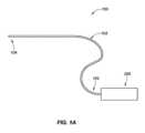
図1Aは、近位制御デバイス200と結合される伸長送達デバイス103を有する、送達システム100の例示的実施形態を描写する、ブロック図である。遠位端領域104が、尿道口を通して患者の尿道(または患者の他の管腔もしくは体腔)の中に挿入されるように適合される。遠位端領域104は、好ましくは、患者への刺激または外傷を最小限にするために、非外傷性構成(例えば、比較的に軟質かつ丸形)を有する。伸長送達デバイス103は、前立腺部尿道内に、またはそれに隣接して送達もしくは展開されるべき1つまたはそれを上回るインプラント102(図示せず)を担持もしくは格納する。送達デバイス103の近位端領域105が、近位制御デバイス200と結合され、これは、患者の身体の外側に留まり、1つまたはそれを上回るインプラント102の送達を制御するために、医師または他の保健医療専門家によって使用されるように構成される。
送達デバイスおよび関連する方法の例示的実施形態FIG. 1A is a block diagram depicting an exemplary embodiment of a
Exemplary embodiments of delivery devices and related methods
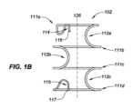
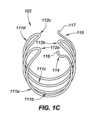
図1B、1C、および1Dは、それぞれ、静止時構成におけるインプラント102の例示的実施形態を描写する、側面図、端面図、ならびに斜視図である。埋込可能デバイス102は、ここで描写される静止時構成に向かって付勢され、静止時構成と送達デバイス103内にインプラント102を格納するための比較的により伸長の格納(または送達)構成(例えば、図3A参照)との間で変形可能である。格納構成は、曲率を殆ど伴わない直線状または線状状態であり得る。静止時構成は、格納構成よりも比較的に大きい側方幅と、比較的に短い縦方向長とを有する。送達デバイス103の開放端から退出することに応じて、インプラント102は、その形状を静止時構成のものに向かって戻るように自由に遷移させるが、患者の尿道壁によって付与される拘束は、インプラント102が静止時構成に完全に到達しないように防止し得る。インプラント102は、静止時構成に向かって付勢されるため、インプラント102は、送達デバイス103の拘束から解放されたときに自動的に拡張するように構成され、「自己拡張式」と称され得る。例えば、患者の尿道内のその展開状態におけるインプラント102の形状は、展開構成と称され得、多くの場合、周辺組織によって静止時構成から変形される形状であろうが、展開構成は、静止時構成と同一であり得る。 1B, 1C, and ID are side, end, and perspective views, respectively, depicting an exemplary embodiment of
インプラント102は、米国特許公開第2015/0257908号および/または国際公開第WO2017/184887号(その両方とも、あらゆる目的のために参照することによって本明細書に組み込まれる)に説明される、それらのインプラント構成のあらゆるものを含む、多数の異なる方法で構成されることができる。
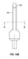
インプラント102は、様々な幾何学形状の1つまたはそれを上回る離散本体(例えば、ワイヤ、リボン、管状部材)から形成されることができる。図1B-1Dの実施形態を参照すると、インプラント102は、所定の形状に設定される唯一の単一のワイヤ部材から形成される主要本体を有する。インプラント102は、隣接するリング形構造111の各対の間に延在する1つまたはそれを上回る相互接続112とともに(本実施形態では、合計3つ、すなわち、112a、112b、および112cのために、各隣接する対の間に1つの相互接続が、存在する)、2つまたはそれを上回るリング形構造111(本実施形態では、4つ、すなわち、111a、111b、111c、および111dが、存在する)を有することができる。各相互接続112は、1つのリング形構造111から直接隣接するリング形構造111まで延在する。各相互接続112は、図1B-1Dに示されるように、比較的に直線状形状(図示せず)または曲線状(例えば、半円形もしくは半楕円形)形状を有することができる。
リング形構造111は、格納構成から拡張されたとき、完全または部分的開放状態において尿道を維持するように構成される。デバイス100は、各リング形構造111の幅(例えば、直径)が、尿道の幅よりもわずかに大きく、各相互接続112の長さが、リング形構造111の間の間隔を判定するように、所望に応じて種々のサイズにおいて製造されることができる。リング形構造111は、同一または異なる幅を有することができる。例えば、ここで描写される実施形態では、リング形構造111aは、同一の幅を有する構造111b-111dよりも比較的に小さい幅を有する。これは、膀胱頸部の前により小さい幾何学形状に収束する、前立腺部尿道に適応することができる。 Ring-shaped structure 111 is configured to maintain the urethra in a fully or partially open condition when expanded from the retracted configuration.
各リング形構造111は、単一の平面内に位置する、または横たわることができ、いくつかの実施形態では、その単一の平面は、(図1Bに描写されるように)インプラント102の中心軸124に垂直な法線軸を伴って配向されることができる。他の実施形態では、リング形構造111は、複数の平面内に位置することができる。リング形構造111は、中心軸126の周囲に延在し、完全な円(例えば、360度回転)を形成することができる、またはここで示されるような完全に満たない円(例えば、360度未満)を形成することができる。そのようなものに限定されないが、多くの実施形態では、リング形構造111は、270~360度に延在する。 Each ring-shaped structure 111 can be located or lie within a single plane, and in some embodiments, that single plane is centered at the center of the implant 102 (as depicted in FIG. 1B). It can be oriented with a normal axis perpendicular to
図1B-1Dから分かり得るように、インプラント102の幾何学形状は、円形または楕円形断面を伴う円筒形もしくは略円筒形の輪郭形状を有することができる。他の実施形態では、インプラント102は、三角形または略三角形断面を伴う、もしくは別様である、角柱もしくは略角柱形状を有することができる。 As can be seen from FIGS. 1B-1D, the geometry of the
インプラント102はまた、それぞれ、送達デバイス103の要素と係合するように構成される、遠位係合部材114と、近位係合部材115とを含むことができる。送達デバイス103との係合は、インプラント102の解放の制御を可能にすること、相互に対するインプラント102の端部の移動を可能にすること、および/または、例えば、医師がインプラント102を再捕捉し、異なる位置においてインプラント102を再展開することを所望する事例において、展開後にインプラント102の回収を可能にすること等の1つまたはそれを上回る目的を果たすことができる。本実施形態では、遠位係合部材114は、送達デバイス103との係合のために好適な場所に非外傷性端部116(例えば、丸形、球形、ボール状)を位置付けるための曲線状(例えば、S字様)形状を有し、それによって、インプラント102の遠位端領域の制御を可能にする、リング形構造111aからのワイヤ様延在部である。同様に、近位係合部材115は、送達デバイス103との係合のために好適な場所に別の非外傷性端部117を位置付け、それによって、インプラント102の近位端領域の制御を可能にするための曲線状形状を有する。他の実施形態では、遠位係合部材114および近位係合部材115は、非外傷性端部116ならびに117が、異なる方向に向くように構成されることができる。例えば、非外傷性端部116および117は、近位に向く代わりに、遠位に向くことができる。別の実施形態では、非外傷性端部116および117は、反対方向に向くことができる(例えば、非外傷性端部116は、遠位に向くことができ、非外傷性端部117は、近位に向くことができ、逆もまた同様である)。他の実施形態では、遠位係合部材114および近位係合部材115は、省略されることができ、送達デバイス103は、リング形構造111もしくは相互接続112の上等の1つまたはそれを上回る他の遠位ならびに/もしくは近位場所においてインプラント102と結合することができる。また、(遠位係合部材114および近位係合部材115と同様に)非外傷性端部を有する延在部が、インプラントの中間部分の設置を制御するための付加的構造を提供するために、インプラント102の中間において取り付けられることができる。
送達デバイス103は、それぞれ、1つまたはそれを上回る内側管腔を有する、1つまたはそれを上回る伸長可撓性部材(例えば、下記に説明されるような120、130、140、および150)を含むことができる。代替として、送達デバイス103の1つまたはそれを上回る伸長可撓性部材は、いかなる内側管腔も伴わない中実または非中空部材であり得る。図2Aは、送達デバイス103の遠位端領域104の例示的実施形態を描写する、斜視図である。本実施形態では、送達デバイス103は、第1の伸長管状部材120と、第2の伸長管状部材130と、第3の伸長管状部材140と、第4の伸長管状部材150とを含む。送達デバイス103は、変動し得、他の実施形態では、より多いまたは少ない管状部材を含むことができる。
本実施形態では、第1の伸長管状部材120は、最外側管状部材であり、可撓性であるが、その中に含有される部材のための支持を提供する。第1の管状部材120は、本明細書では外側シャフト120と称され、1つまたはそれを上回る内側管腔を有することができる。本実施形態では、外側シャフト120は、本明細書では内側シャフト130と称される、第2の伸長管状部材130を格納する、第1の内側管腔121を含む。外側シャフト120および内側シャフト130は、それぞれ、他方から独立して制御可能である。内側シャフト130は、管腔121内で遠位および近位に摺動することができ、ここでは、外側シャフト120の開放遠位末端から部分的に延在して示される。 In this embodiment, the first elongate
本実施形態では、外側シャフト120は、3つの付加的管腔122、123、および124を含む。照明デバイス(図示せず)および撮像デバイス(図示せず)が、管腔122-124のうちの2つ(例えば、管腔122および123)の中に格納されることができる。撮像デバイスは、光学または超音波撮像等の任意の所望のタイプの撮像モダリティを利用することができる。一例示的実施形態では、撮像デバイスは、前(遠位)向きのCMOS撮像装置を利用する。照明デバイスは、光学撮像のための適正な照明を提供するように構成されることができ、一実施形態では、1つまたはそれを上回る発光ダイオード(LED)を含む。超音波撮像のため等に照明が要求されない実施形態では、照明デバイスおよびその個別の管腔は、省略されることができる、または管腔は、代替目的のために、例えば、潅注もしくは洗除チャネルとして使用され得る。照明デバイスおよび/または撮像デバイスは、それぞれ、管腔122ならびに123の遠位末端において固定して固着されることができる、またはそれぞれ、外側シャフト120から遠位へのさらなる前進ならびに/もしくは外側シャフト120の中への後退を可能にするように、管腔122および123内で摺動可能であり得る。一例示的実施形態では、照明デバイスおよび撮像デバイスは、ともに搭載され、単一の管腔122または123のみが、その目的のために存在する。残りの管腔(例えば、管腔124)は、それから生理食塩水等の流体が尿道に導入され、領域を洗除し、それを通してインプラント102および周辺前立腺部尿道壁が撮像され得る、適正な流体を提供し得る、潅注または洗除ポートとして構成されることができる。一実施形態では、外側シャフトは、流体管理のために2つの別個の管腔を含有してもよい。一方の管腔は、潅注のために使用されてもよく、他方の管腔は、洗除のために使用されてもよい。 In this embodiment,
外側シャフト120は、近位制御デバイス200と結合される、近位端(図示せず)を有する。送達デバイス103は、蛇行性の解剖学的構造をナビゲートするように操向可能であるように構成されることができる。操向可能性は、用途の必要性に応じて、一方向(例えば、単一の引動ワイヤを使用する)または多方向(例えば、デバイス103を中心として異なる半径方向場所に配列される2つまたはそれを上回る引動ワイヤを使用する)であり得る。いくつかの実施形態では、操向可能性のための構造(例えば、引動ワイヤ)は、送達デバイス103の遠位端領域104(例えば、引動ワイヤの遠位端が遠位端領域104内の板または他の構造に固着される)から、それらが送達デバイス103を操向するようにユーザによって操作され得る、近位制御デバイス200まで延在する。操向構造は、外側シャフト120の1つまたはそれを上回る管腔内に位置することができる、もしくは外側シャフト120の側壁に結合される、またはその中に埋設されることができる。送達デバイス103は、デバイス103が、その様式で自動的に偏向し、送達デバイス103を操向するように付与される力が、本付勢偏向と反対であるように、特定の側方方向に偏向する(例えば、屈曲する)ように付勢されることができる。送達デバイス103を操向するための他の機構もまた、使用されることができる。操向機構はまた、解剖学的構造内のインプラント102の位置を制御するために、インプラント102の展開の間に係止または調節されてもよい(例えば、展開の間に前方に操向することは、より望ましい前方位置にインプラント102を設置することに役立ち得る)。
内側シャフト130は、1つまたはそれを上回るインプラント102ならびに/もしくは他の構成要素を格納するための1つまたはそれを上回る内側管腔を含むことができる。本実施形態では、内側シャフト130は、1つまたはそれを上回るインプラント102が格納され得る、第1の管腔131と、第3の伸長管状部材140が格納され得る、第2の管腔132とを含む。本実施形態では、第3の伸長管状部材140は、インプラント102の遠位端領域と解放可能に結合するように構成され、遠位制御部材またはテザー140と称される。遠位制御部材140は、内側シャフト130に対して摺動可能に前進および/または後退されることができる。遠位制御部材140は、ここでは遠位制御部材140の開放遠位末端から延在して示される、第4の伸長管状部材150を格納する、内側管腔141を含むことができる。第4の伸長管状部材150は、患者の解剖学的構造に対して送達デバイス103を係留し、例えば、インプラント102の展開の間に送達デバイス103の構成要素を解剖学的構造に対して定常に保つように構成され、アンカ送達部材150と称される。
図2Aに描写される構成では、アンカ送達部材150は、遠位制御部材140の管腔141から延在され、遠位制御部材140は、内側シャフト130とともに、外側シャフト120の管腔121から延在されて示される。送達デバイス130が、尿道を通して前進されるとき、アンカ送達部材150は、好ましくは、完全に遠位制御部材140内に格納され、遠位制御部材140は、内側シャフト130とともに、それらが、外側シャフト120の管腔121内に存在し、管腔120の開放遠位末端から延在しないように、図2Aに示される位置から後退される。言い換えると、いくつかの実施形態では、外側シャフト120の開放遠位末端は、尿道を通した初期前進に応じて、デバイス103の最遠位構造を形成する。これは、外側シャフト120による送達デバイス103の操向を促進する。医師は、所望の埋込部位と近接するように、または完全に患者の膀胱の中に、送達デバイス103の遠位端領域104を前進させることができる。アンカ送達部材150は、アンカ送達部材150をさらに膀胱の中に遠位に前進させることによって、またはすでに膀胱内に存在している場合、送達デバイス103の他の構成要素を近位に後退させることによってのいずれかで、遠位制御部材140の開放遠位末端から暴露されることができる。この時点で、アンカ送達部材150からのアンカは、膀胱内で展開されることができる。 In the configuration depicted in FIG. 2A,
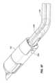
図2Bは、種々の構成要素が展開される、送達デバイス103の遠位端領域104を描写する、斜視図である。本実施形態では、アンカ送達部材150は、膨張可能部材またはバルーンの形態におけるアンカ152を含む。 FIG. 2B is a perspective view depicting the
アンカ152の他の実施形態が、2019年5月16日に出願された国際出願第PCT/US19/32637号(あらゆる目的のために参照することによってその全体として本明細書に組み込まれる)に説明されている。アンカ152は、アンカ152が、近位後退(例えば、比較的に軽い張力)に抵抗するように、膀胱頸部のものを上回るサイズまで拡張する(または別様に遷移する)。アンカ152がバルーンである実施形態では、そのバルーンは、弾性もしくは非弾性であり、1つまたはそれを上回る膨張ポート153を通してバルーン152の中に導入される膨張媒体(例えば、空気もしくは生理食塩水等の液体)を用いて膨張可能であり得る。ここでは、3つの膨張ポート153が、アンカ送達部材150のシャフト上に位置し、シリンジを用いた膨張のためのポートを含み得る、近位制御デバイス200に戻るように近位に延在する膨張管腔と連通する。アンカ152の展開に応じて、医師は、アンカ152が(まだ接触していない場合)膀胱頸部および/または壁と接触するまで、送達システム100を近位に後退させることができる。 Other embodiments of
医師は、外側シャフト120の撮像デバイスを使用し、医師がインプラント102の展開を開始するために尿道内の所望の位置に来るまで、アンカ152から離れるように近位に送達デバイス103を移動させることができる。遠位制御部材140上の保定器142が、インプラント102の遠位係合部材114と解放可能に結合される。医師は、医師がインプラント102の遠位端が展開することを所望する、尿道の長さに沿った場所に保定器142を位置付けることができる。これは、アンカ送達部材150に対して近位および/または遠位に、遠位制御部材140ならびに内側シャフト130をともに移動させることを伴うことができる。別の実施形態では、保定器142の位置は、解剖学的構造内のインプラント102の縦方向位置が、医師によるいずれの操作からも独立して本システムによって設定されるように、アンカ152に対して固定される。保定器142との遠位係合部材114の結合はまた、遠位制御部材140および内側シャフト130をともに回転させることによって、医師がインプラント102の半径方向配向を操作することを可能にする。遠位制御部材140の能動または受動成形は、インプラント102のより望ましい設置を可能にし得る。例えば、部材140は、より前方の解剖学的位置にインプラントを設置する曲率を有してもよい。本曲率は、部材150内で本質的に設定される、または制御ワイヤ等の別個の実体を通して医師によって能動的に適用されてもよい。いったん所望の場所および配向に来ると、医師は、遠位制御部材140に対して内側シャフト130を近位に後退させ、インプラント102の展開を開始することができる。 Using the imaging device on
遠位係合部材114は、保定器142によって遠位制御部材140に対して定位置に保持され、遠位制御部材140に対する内側シャフト130の近位後退は、リング形構造111を順に(111a、次いで、111b、次いで、111c、次いで、111d(図示せず))展開し始めさせる。遠位制御部材140は、展開の間に尿道に対して定常のままである、または縦方向に移動されることができる。いくつかの実施形態では、遠位制御部材140は、インプラント102の角形成を可能にし、比較的に蛇行性の解剖学的構造に適応するように操向可能である。遠位制御部材140の操向可能性はまた、膀胱頸部に対するインプラントの比較的に前方の設置を遂行することができ、これは、潜在的に、改良された流動結果に寄与する。例えば、図2C-2Gならびに図10Cおよび10Dに示されるような遠位制御部材140を参照されたい。操向可能性を遂行するための機構は、本明細書の別の場所に議論され、同様に遠位制御部材140に適用されることができる。これらまたは他の実施形態では、遠位制御部材140は、蛇行性解剖学的構造に受動的に適応するように有意に可撓性であり得る。いくつかの実施形態では、遠位制御部材140は、所定の曲線を有し、ナビゲーションを支援する。
展開を支援するために、内側シャフト130は、遠位制御部材140を中心として時計回りおよび反時計回りに(矢印134によって描写されるように)回転することができる。再び図1B-1Cを参照すると、インプラント102は、遠位係合部材114から始まると見なされると、近位係合部材115において終了するまで、リング形構造111aに沿って時計回りに進み、次いで、リング形構造111bに関して相互接続112aに沿って反時計回り方向に逆転し、次いで、リング形構造111cに関して相互接続112bに沿って時計回り方向に逆転し、次いで、リング形構造111dに関して相互接続112cに沿って反時計回り方向に逆転する、一定ではない巻回の方向を有する。管腔131の開放遠位末端から退出しようとしているインプラント102の一部の巻回の方向に応じて、静止時構成に向かうインプラント102の遷移は、インプラント102が展開されるにつれて、シャフト130が能動的に回転されない場合、シャフト130上にトルクを付与することができる。そのトルクは、それに応じて、シャフト130を時計回りまたは反時計回りのいずれかに受動的に(ユーザ介入を伴わずに)回転させることができる。本明細書の別の場所に説明される、ある実施形態では、シャフト130は、展開の間に能動的に回転される。遠位制御部材140に対する内側シャフト130の回転は、したがって、送達デバイス103が回転し、インプラント102の巻回の方向に従うことを可能にする。いくつかの実施形態では、全てのリング形構造111は、(例えば、完全渦巻状または螺旋インプラントの場合におけるように)時計回りもしくは反時計回りの同一の方向に巻回される、または設定された巻回の方向を有していない。 To assist in deployment,
本または他の実施形態では、内側シャフト130の遠位端領域は、内側シャフト130のより近位の部分よりも比較的に可撓性であるように構成され、これは、展開の間に残りのデバイス103の過剰な運動の回避を可能にし、より良好な可視化およびデバイス103によるより少ない組織接触をもたらすことができる。そのような構成はまた、送達の間にデバイス103によってインプラント102に対して付与される応力を低減させることができる。例えば、展開の間に外側シャフト120から延在する内側シャフト130の一部は、外側シャフト120内に留まる内側シャフト130の一部よりも比較的に可撓性であり、したがって、インプラント102が内側管腔131から退出するにつれて、内側シャフト130がより容易に撓曲することを可能にすることができる。これは、ひいては、送達デバイス103を安定させ、医師が定置プロセスの安定した画像を取得することを可能にすることができる。 In this or other embodiments, the distal end region of
代替実施形態では、図4A-4Eに見られるように、内側シャフト230は、外側トルク付与管233(図4B-4E)と、1つまたはそれを上回るインプラント102ならびに/もしくは他の構成要素を格納するための1つまたはそれを上回る管腔と、1つまたはそれを上回るトルク付与支持体235とを含むことができる。本実施形態では、内側シャフト230は、1つまたはそれを上回るインプラント102が格納され得る、第1の管腔231を有する、第1の伸長管状部材231aを含む。第1の伸長管状部材231aはまた、膨張管腔として作用し得る、第3の伸長管状部材140および第4の伸長管状部材240が格納され得る、第2の管腔232を有する、第2の伸長管状部材232a(またはテザー)を有する。代替実施形態では、第2の伸長管状部材232a(またはテザー)は、解放/作動のために使用されることができ、膨張管腔は、テザーと同心であり得る。図4Dおよび4Eに見られるように、第1の伸長管状部材231aおよび第2の伸長管状部材232aは、並んで着座し、トルク付与支持体235によって定位置に保持されることができる。トルク付与支持体235は、外側トルク付与管233の近位端から遠位端まで外側トルク付与管233内に離間される、小さい板であり得る。例えば、トルク付与支持体235は、約3~約6インチ離れて、代替として、約2~約5インチ離れて、代替として、約1~約4インチ離れて設置されてもよい。トルク付与支持体235は、外側トルク付与管233の軸方向および角度位置が、ユーザによって維持され得ることを確実にするために、外側トルク付与管233に対して定位置に接合される、または別様に固定されることができる。第1の伸長管状部材231aは、第1の伸長管状部材231aが、外側トルク付与管233に伴って移動することを確実にするために、トルク付与支持体235に固定されることができる。第2の伸長管状部材232aは、第2の伸長管状部材232aが、支持板および外側トルク付与管233に対して軸方向に回転的に移動し得るように、トルク付与支持体235に固定されなくてもよい。 In an alternative embodiment, as seen in FIGS. 4A-4E, the
図4Bに見られるように、可撓性先端243は、その遠位端237が、約0cm~1.5cm、代替として、約0cm~1.0cm、代替として、約0.2~1.0cmだけ外側トルク付与管233の遠位先端239を越えて延在するように、第1の伸長管状部材またはインプラント送達管231aを固定することによって作成されてもよい。 As seen in FIG. 4B, the
内側シャフトの構成要素は、適切な材料から作製されてもよい。第1の伸長管状部材またはインプラント送達管231aは、潤滑性ライナを伴う編組管状アセンブリであってもよい。これは、潤滑性ライナを伴うレーザ切断されたハイポチューブ、単一のポリマー押出物、または他の適切な材料から作製されてもよい。外側トルク付与管233は、レーザ切断されたハイポチューブ、編組構造体、ポリマー押出物、または他の適切な材料から作製されてもよい。トルク付与支持体235は、レーザ切断された金属板、成型されたプラスチック構成要素、押出された材料、または他の適切な材料であってもよい。 The inner shaft components may be made from suitable materials. The first elongated tubular member or
図2Bは、3つのリング形構造111a、111b、および111cが展開された後のインプラント102を描写する。シャフト130の近位後退は、インプラント102の全体またはリング形構造111の少なくとも全てが管腔131から退出するまで継続する。医師が、インプラント102の展開された位置およびインプラント102の展開された形状に満足している場合、インプラント102は、送達デバイス103から解放されることができる。制御ワイヤ146(図2Bに図示せず)が、アンカ送達部材150と同一の管腔内で、または異なる管腔内でのいずれかで、制御部材140の長さ内に延在し、保定器142に結合される。制御ワイヤ146は、開口部148を通して部材140の中に配策されることができる。 FIG. 2B depicts the
インプラント102の遠位端の解放は、保定器142を解放することによって遂行されることができる。保定器142は、インプラント102の一部が格納される、空洞または陥凹にわたって線形に、もしくは回転的に作動する、円筒形構造または他のスリーブであり得る。図2Bの実施形態では、保定器142は、遠位係合部材114がそれを通して通過することを可能にする、開口部またはスロットを含む。保定器142は、開口部またはスロットが部材114にわたって位置付けられ、その時点で部材114が自由に遠位制御部材130から解放されるまで、遠位係合部材114(図示せず)が格納される空洞または陥凹に対して回転することができる。保定器142の回転は、保定器142と結合される(かつ近位制御デバイス200においてアクセス可能である)回転可能シャフト、ロッド、または他の部材の回転によって遂行されることができる。保定器の代替実施形態が、2019年5月16日に出願された国際出願第PCT/US19/32637号(あらゆる目的のために参照することによってその全体として前述に組み込まれている)の図2C-2Fに見出されることができる。 Releasing the distal end of
図2C-2Gは、テザーロックを用いて定位置に固定され得る代替保定器142を伴う、システム100の別の例示的実施形態を描写する、斜視図である。他の実施形態におけるように、保定器142は、遠位制御部材140に対して遠位および/または近位に摺動する。インプラント102の遠位係合部材114は、遠位制御部材140の対応する陥凹143(図2G)内に受容されることができる。保定器142は、保定器142が、その遠位端の近傍に位置する開口部241を有する、部材140の一部に当接するまで、本陥凹143内に受容されながら、遠位係合部材114にわたって摺動することができる。制御ワイヤ246が、アンカ送達部材150と同一の管腔内で、または異なる管腔内でのいずれかで、制御部材140の長さ内に延在し、その遠位端248において保定器142に取り付けられる、または結合する。図2Eに見られるように、制御ワイヤ246は、制御部材246が、開口部から突出し、遠位制御部材の縦方向軸および保定器142の縦方向軸に垂直な軸に沿って延在するループ247を形成するように、遠位制御部材140内の開口部241から外に通過し、その中に戻るように通過する。保定器142に隣接して、その近位に位置するループ247は、保定器142が遠位制御部材140にわたって近位方向に移動しないように防止する。 2C-2G are perspective views depicting another exemplary embodiment of
例えば、図2Cの状態における、尿道内のインプラント102の満足の行く展開に応じて、制御ワイヤ246は、制御ワイヤ246を近位方向に(インプラント102から離れるように)引動することによって架張されることができる。図2Fに見られるように、張力は、ループ247を遠位制御部材140の管腔の中に引動し、それによって、保定器142が近位に摺動しないように防止する障害物を除去する。図2Gに見られるように、ループが、遠位制御部材140の管腔の中に抜去された後、保定器140は、係合部材114を暴露し、部材140からのその解放を可能にするように制御ワイヤ246を近位にさらに引動することによって、近位に後退される。 For example, upon satisfactory deployment of the
制御部材146、246は、ニチノール、ケブラ、ステンレス鋼、縫合糸、液晶ポリマー(LCP)、または任意の他の架張可能材料から作製されてもよい。
図2H-2Jは、定位置に固定され得る代替保定器242を伴う、システム100の別の例示的実施形態を図示する。説明される他の実施形態のように、保定器242は、インプラント102の一部が格納される、空洞または陥凹にわたって線形に、もしくは回転的に作動する、円筒形構造または他のスリーブであり得る。保定器242は、制御デバイス200まで延在する外側管249に結合される、カバー245を含む。図2H-2Jの実施形態では、保定器242は、遠位係合部材114がそれを通して通過することを可能にする、開口部またはスロット(図示せず)を含む。図2Hは、遠位係合部材114を保持するように適合される、陥凹143にわたって閉鎖される、カバー245を示す。保定器242は、開口部またはスロットが部材114にわたって位置付けられ、その時点で部材114が自由に遠位制御部材130から解放されるまで、遠位係合部材114が格納される空洞または陥凹に対して近位に抜去されることができる。図2Iに見られるように、カバー245は、外側管249を近位に作動させることによって抜去されている。保定器242のカバー245の抜去は、近位制御デバイス200においてアクセス可能である、外側管249を近位に抜去することによって遂行されることができる。図2Jは、保定器242と、アンカ152と連通する膨張管腔とを示す、断面である。アンカバルーンの膨張直径は、約1cm~7cm、代替として、約2cm~6cm、代替として、約1cm~6cmであり得る。 2H-2J illustrate another exemplary embodiment of
インプラント102の近位端の解放もまた、制御可能である。図3Aは、インプラント102の一部が内側シャフト130の内側管腔131内に示される、システム100の例示的実施形態を描写する、部分断面図である。ここでは、インプラント102は、近位係合部材115が管腔131内で遠位および/または近位に摺動可能である把持器136と結合される、展開に先立つ線状状態にある。把持器136は、シャフト138上に、またはそれと結合される、遠位端領域137を含むことができる。把持器136は、好ましくは、内側シャフト130に対してインプラント102を回転させ、縦方向に平行移動させる(例えば、押動および引動する)ように制御可能である。 Release of the proximal end of
図3Bおよび3Cは、それぞれ、インプラント102を伴わない、ならびにインプラント102を伴う、把持器136の遠位端領域137の例示的実施形態を描写する、斜視図である。把持器136は、近位係合部材115を受容および保持するための陥凹(空洞またはポケットとも称される)139を含む。ここで、拡大部分115は、比較的により小さい幅を有する遠位縮径状領域によって、陥凹139内で保定される。内側管腔131内にある間に、内側シャフト130の側壁は、陥凹139内に近位係合部材115を維持する。遠位端領域137が、(把持器136に対して内側シャフト130を後退させることによって、または内側シャフト130に対して把持器136を前進させることによってのいずれかで)内側管腔131から退出するとき、内側シャフト側壁によって付与される拘束は、もはや存在しなくなり、係合部材115は、自由に把持器136から解放される。したがって、医師が、展開されたインプラント102の設置に満足しているとき、遠位係合部材114は、保定器142を移動させ、遠位係合部材114が制御部材140から結合解除されることを可能にすることによって、解放されることができ、近位係合部材115は、内側シャフト130内から把持器136を暴露し、近位係合部材115が把持器136から結合解除されることを可能にすることによって、解放されることができる。 3B and 3C are perspective views depicting an exemplary embodiment of a
把持器136はまた、インプラント102を装填することを支援することができる。いくつかの実施形態では、(インプラント102の反対端部が、例えば、保定器142によって固着されている間の)把持器136を用いたインプラント102に対する引張力の印加は、静止時構成から内側シャフト130の中へのインプラント102の挿入のために好適な線状構成へのインプラント102の遷移を促進する。
アンカ送達部材150は、複数の異なる構成および幾何学形状(例えば、膀胱壁を横断して1つの方向、膀胱壁を横断して2つの方向(例えば、左および右)、もしくは膀胱壁を横断して3つまたはそれを上回る方向に延在するものを含む)を有することができる。アンカ送達部材およびアンカの付加的実施例が、2019年5月16日に出願された国際出願第PCT/US19/32637号(あらゆる目的のために参照することによってその全体として前述に組み込まれている)の図2Bおよび4A-4Jに説明されている。
インプラント展開手技の完了に応じて、アンカ152は、送達デバイス103の除去を可能にするように圧潰または後退されることができる。例えば、アンカ152がバルーンである実施形態では、そのバルーンは、収縮され、随意に、デバイス103の管腔の中に戻るように後退され、続いて、膀胱および尿道から抜去される。アンカ152がワイヤ形態または他の拡張可能部材(2019年5月16日に出願された国際出願第PCT/US19/32637号(あらゆる目的のために参照することによってその全体として前述に組み込まれている)の図4A-4Gに関して説明されるもの等)である実施形態では、アンカ152は、それからこれが展開されたデバイス103の管腔の中に戻るように後退され、デバイス103は、続いて、膀胱および尿道から抜去されることができる。後退は、流体または空気圧式作動、ねじタイプ機構、もしくはその他を使用して遂行されることができる。
近位制御デバイスおよび関連する方法の例示的実施形態Upon completion of the implant deployment procedure,
Exemplary embodiments of proximal control devices and related methods
図5Aは、インプラント102の展開に先立つ送達システム100の例示的実施形態を描写する、側面図であり、図5Bは、展開構成におけるインプラント102を伴う本実施形態を描写する、側面図である(アンカ送達部材150および遠位制御部材140は、示されていない)。本実施形態では、近位制御デバイス200は、取っ手201と、第1のユーザアクチュエータ202(本実施例ではトリガとして構成される)と、主要本体203と、第2のユーザアクチュエータ205とを有する、ハンドヘルドデバイスである。送達デバイス103の縦方向軸が、破線204によって示される。近位制御デバイス200は、デバイス103の構成要素の相対運動を引き起こすようにアクチュエータ202の作動によって手動で給電される機構を含むことができる。他の実施形態では、近位制御デバイス200は、代わりに、電動機構を利用することができる。第2のユーザアクチュエータ205は、送達デバイス103の操向を制御するように構成されることができる。ここでは、図5Gおよび5Hに見られるように、アクチュエータ205は、送達デバイス103内の引動ワイヤ221を巻回または巻解し、ここで描写されるように、上向きおよび下向きにデバイス103の偏向を引き起こし得る、回転可能車輪225として構成される。第2のユーザアクチュエータ205は、延在部212の第1の端部215から延在するパドル206を有する、延在部212を含む。図5Aに見られるように、展開に先立って、延在部212は、取っ手201により近接し、例えば、延在部212は、取っ手201に向かって角度付けられる。図5Bに見られるように、インプラント102が、少なくとも部分的に、遠位端領域104から展開された後、延在部212は、取っ手201から離れるように角度付けられ、遠位端領域104に向かって角度付けられる、または向けられる。図5Bの点線はまた、内側管状部材120の遠位端が、インプラントをさらに前方に設置することを可能にするように偏向され得ることを示す。近位制御デバイス200は、リング形構造111の全てが内側管腔131から展開された後であるが、管腔131内からの近位係合特徴115および陥凹139の前進に先立って、インプラント102のさらなる展開が、自動的に防止されるように構成されることができる。これは、送達デバイス103からインプラント102を解放することに先立って、インプラント102が適切に展開および設置されていることを検証する機会を医師に提供する。制御デバイス200ならびにその中に含有される部品および歯車アセンブリの詳細な説明が、例えば、2019年5月16日に出願された国際出願第PCT/US19/32637号(あらゆる目的のために参照することによってその全体として前述に組み込まれている)の図6A-9Fに見出されることができる。 5A is a side view depicting an exemplary embodiment of
本デバイスはまた、ユーザが操向を前方に係止し、インプラントをより前方の位置に設置することを可能にする、操向ロックを含んでもよい。前述で議論されるように、本デバイスの操向可能性は、送達デバイス103の遠位端領域104(例えば、引動ワイヤの遠位端が遠位端領域104内の板または他の構造に固着される)から、それらが送達デバイス103を操向するようにユーザによって操作され得る、近位制御デバイス200まで延在する、引動ワイヤ225を含むことができる。操向構造は、外側シャフト120の1つまたはそれを上回る管腔内に位置することができる、もしくは外側シャフト120の側壁に結合される、またはその中に埋設されることができる。送達デバイス103は、デバイス103が、その様式で自動的に偏向し、送達デバイス103を操向するように付与される力が、本付勢偏向と反対であるように、特定の側方方向に偏向する(例えば、屈曲する)ように付勢されることができる。 The device may also include a steering lock that allows the user to lock the steering forward and place the implant in a more anterior position. As discussed above, the steerability of the present device is dependent on the
操向ロックは、アクチュエータ205に取り付けられる延在部212の部分である。図5C-5Hに見られるように、アクチュエータ205は、回転可能車輪225と、延在部212と、ラッチ209と、レッジ207とを含む。アクチュエータ205の筐体は、2つの半体、すなわち、右取っ手半体205aと、左取っ手半体205bとを含んでもよい。回転可能車輪225は、引動ワイヤを巻回および巻解するように適合され、筐体内に位置し、それに結合される。延在部212は、ラッチ209と、パドル206とを含み、これは、第1の端部215から延在し、間隙が、戻り止め208と延在部212の第2の端部217との間に存在するように、戻り止め208において終端する。延在部212の第2の端部217は、左取っ手半体205bに取り付けられ、第1の端部は、右取っ手半体205aの一部に隣接する。延在部212の第2の端部217は、戻り止め208と、間隙とを含む。操向ロックはまた、筐体の右取っ手半体205aから延在部212の第1の端部215に近接して延在する、レッジ207を含む。ラッチ209は、パドル206に沿って作動または摺動するように適合される。ラッチ209が、第2の端部217上に位置するとき、戻り止め208は、ラッチ209に摩擦して係合し、それによって、ラッチ209を第2の端部217に拘束する。 The steering lock is the part of the
使用時、図5Eに見られるように、ユーザは、戻り止め208からラッチ209を係脱させ、パドル206に沿って延在部212の第2の端部217から第1の端部215にラッチ209を移動させることができる。いったんラッチ209が、第1の端部215に来ると、延在部212は、ラッチ209がレッジ207と接触するまで、ユーザによって遠位端領域104に向かう方向に押動されることができる。レッジ207は、次いで、ラッチ209に摩擦して係合し、「係止」位置において遠位端領域104に向かって角度付けられる位置に延在部212を保持する。係止位置において、回転可能車輪225は、引動ワイヤ221を巻回または巻解することができず、ユーザは、外側管状部材103の遠位端領域104を移動させる(偏向または直線化させる)ことができない。図5Fに見られるように、「係止」位置からパドル206を解放するために、ユーザは、レッジ207からラッチ209を解放し、パドル206に沿って延在部212の第1の端部215から第2の端部217にラッチ209を摺動させることができる。ラッチ209が、もはやレッジ207によって摩擦して係合されなくなると、延在部212は、延在部212が、ばね荷重に起因して取っ手201に向かって(すなわち、遠位端領域104から離れるように)角度付けられる、静止位置に受動的に戻ることができる。係止解除位置において、回転可能車輪225は、引動ワイヤ221を巻回および巻解し、それによって、外側管状部材103の遠位端領域104を移動させる(偏向または直線化させる)ことが可能である。
送達方法の例示的実施形態In use, the user disengages the
Exemplary embodiments of delivery methods
図6Aは、システム100を使用してインプラント102を送達する方法1000の例示的実施形態を描写する、フロー図である。外側シャフト120の遠位端領域は、好ましくは、いかなる部分も、外側シャフト120の開放遠位末端から延在していないように、後退状態において外側シャフト120内に完全に含有された内側シャフト130、遠位制御部材140、およびアンカ送達部材150を伴って、尿道の中に挿入される。尿道の中への前進後、ステップ1002において、アンカ送達部材150は、送達デバイス103の残りの部分(例えば、部材120、130、および140)に対して遠位に前進され、膀胱内でアンカ152を展開するために使用される。いくつかの実施形態では、アンカ152の展開は、注入(例えば、ルアーテーパ)ポートを通した膨張媒体の導入による、(例えば、図2Bに描写されるような)1つまたはそれを上回るバルーンの膨張であり得る。アンカ送達部材150および/または任意のワイヤ形態部材の縦方向位置付け(例えば、前進ならびに後退)は、直接または近位制御デバイス200を用いてのいずれかで、ユーザがアンカ送達部材150ならびに/もしくは任意のワイヤ形態部材の近位端を操作することによって、手動で遂行されることができる。 FIG. 6A is a flow diagram depicting an exemplary embodiment of a method 1000 of delivering an
ステップ1004において、アンカ152は、デバイス200に対する近位に指向された力の付与によって、膀胱壁に対して張力を受けて保持されることができる。アンカ152は、したがって、それから正確な場所においてインプラント102を展開する、システム100のための縦座標を提供することができる。本特徴は、インプラントが膀胱頸部に接近しすぎた状態で設置されないことを確実にすることができる。 At step 1004,
1006において、遠位制御部材140および内側シャフト130は、次いで、それらがまだそうではない場合、外側シャフト120内から遠位に前進されることができる(例えば、ステップ1006は、ステップ1002および/または1004に先立って行われることができる)。ユーザは、インプラント102が所望の位置に来るまで、(本明細書に説明されるような)撮像を用いて近位制御デバイス200の位置を操作することができる。いったんインプラント102が、所望の位置に来ると、インプラント展開手技が、開始されることができる。インプラント展開のためのステップは、近位制御デバイス200のユーザ作動(例えば、トリガ202の作動、スイッチ604のための位置の選択等)によって自動的に実施されることができる、またはステップは、送達デバイス103の各構成要素の手動操作によって、もしくは特定の実装のための所望に応じた2つの組み合わせによって、直接実施されることができる。 At 1006,
いくつかの実施形態では、管腔131内からのインプラント102の展開は、(1)内側シャフト130が移動されていない間、内側シャフト130に対して把持器136を遠位に前進させることによって、完全に遂行される一方、他の実施形態では、内側管腔131内からのインプラント102の展開は、(2)把持器136が移動されていない間、把持器136に対して内側シャフト130を近位に後退させることによって、完全に遂行される。いくつかの実施形態では、インプラント102の展開は、(3)両方の移動の組み合わせによって、完全に遂行される。なおも他の実施形態では、インプラント102の展開は、遠位制御部材140に対する1つまたはそれを上回る方向(例えば、時計回りもしくは反時計回り)における内側シャフト130の1つまたはそれを上回る回転と組み合わせて、(1)、(2)、もしくは(3)によって、完全に遂行される。 In some embodiments, deployment of
インプラント102を展開するためのステップ1008、1010、および1012のシーケンスの例示的実施形態が、図6Aならびに図6Bのタイミング図を参照して説明される。最初に図6Aを参照すると、ステップ1008において、第1のリング形構造111aが、内側シャフト130の管腔131から退出させられ、ステップ1010において、相互接続112が、管腔131から退出させられ、ステップ1012において、第2のリング形構造111bが、管腔131から退出させられる。ステップ1010および1012は、インプラント102上に存在する付加的相互接続112ならびにリング形構造111毎に繰り返されることができる。 An exemplary embodiment of the sequence of steps 1008, 1010, and 1012 for deploying
図6Bでは、ステップ1008は、T0においてタイミング図の左端から開始される。リング形構造111aの展開は、1008とマーキングされた持続時間に対応し、相互接続123の展開は、期間1010に対応し、リング形構造111bの展開は、期間1012に対応する。当業者は、インプラント102のそれらの部分の間の遷移が、漸進的であり得、精密な境界を有する必要性がないため、リング形構造111の展開と相互接続112の展開との間の区別が、近似であることを認識するであろう。 In FIG. 6B, step 1008 begins at the left end of the timing diagram at T0. The deployment of ring-shaped
図6Bに関して説明される実施形態は、反対の巻回方向(例えば、時計回り、次いで、反時計回り、次いで、時計回り等)を有する、リング形構造111を伴うインプラントに関するものである。3つの異なる運動が、図6Bに示される。上は、1つの方向(例えば、時計回り)における内側シャフト130の回転運動であり、中央は、送達デバイス103の1つまたはそれを上回る構成要素の縦方向運動(例えば、近位もしくは遠位)であり、下は、上に示されるものと反対の方向(例えば、反時計回り)における内側シャフト130の回転運動である。インプラント102のリング形構造111が全て、同一の1つの方向に巻回される実施形態では、内側シャフト130の回転もまた、1つのみの方向にあろう。 The embodiment described with respect to FIG. 6B is for an implant with a ring-shaped structure 111 having opposite winding directions (eg, clockwise, then counterclockwise, then clockwise, etc.). Three different movements are shown in Figure 6B. Top is rotational movement of
時間T0からT1まで、インプラント102の展開は、領域1031に示されるように、内側シャフト130を回転させることによって遂行される。同時に、領域1032では、把持器136、したがって、インプラント102は、外側シャフト120を縦方向にも(遠位にも、または近位にも)、もしくは回転的にも移動させることなく、また、内側シャフト130を(遠位にも、または近位にも)縦方向に移動させることなく、遠位に前進される。 From time T0 to T1, deployment of
時間T1からT2まで、内側シャフト130の回転は、停止されるが、把持器136の遠位前進が、継続する一方、シャフト120および130は、縦方向に移動しない。 From time T1 to T2, rotation of
時間T2からT4まで、第1の相互接続112の展開が、起こる。領域1033では、時間T2からT4まで、把持器136(およびインプラント102)のいかなる遠位前進も、起こらない。相互接続112の展開は、定位置で把持器136を保持しながら、外側シャフト120および内側シャフト130の両方の近位後退によって遂行される。これは、相互接続112をシャフト130の内側管腔131から退出させる。 From time T2 to T4, deployment of the first interconnect 112 occurs. In region 1033, no distal advancement of grasper 136 (and implant 102) occurs from time T2 to T4. Deployment of interconnect 112 is accomplished by proximal retraction of both
内側シャフト130の回転に対して、時間T2からT3まで、内側シャフト130のいかなる回転も、起こらない。近位制御デバイス200内で、環状歯車802の断続部分は、継続し、中心歯車816によるシャフト130のいかなる回転も、存在しない。 With respect to the rotation of
相互接続112が直線状である実施形態では、次いで、相互接続112が時間T2からT4まで展開されている間、シャフト130を回転させることを控えることが、望ましくあり得る。図1B-1Dの実施形態等の相互接続112が曲線状である実施形態に関して、相互接続展開の間に内側シャフト130の回転を開始することが、望ましくあり得る。図6Bは、曲線状相互接続112のための展開を描写し、T3からT4まで、内側シャフト130は、領域1034によって示されるように反対方向に回転される。 In embodiments where interconnect 112 is straight, it may then be desirable to refrain from
T4において、相互接続112の展開が、完了し、第2のリング形構造111bの展開が、開始される。シャフト120および130の近位後退は、領域1033の中断によって示されるように停止される。把持器シャフト138の遠位前進が、T4において領域1035内で再開される一方、外側シャフト120は、回転的にも、または縦方向にも移動されない。内側シャフト130の回転は、領域1034に示されるように継続するが、内側シャフト130は、縦方向に移動されない。 At T4, deployment of interconnect 112 is completed and deployment of second ring-shaped
これらの運動は、時間T5まで継続し、その時点で、内側シャフト130の回転は、停止される。近位制御デバイス200内で、環状歯車802の断続部分に到達され、歯車802が、遊星歯車から係脱し、中心歯車816の回転が、停止される。トリガ202のユーザ押下は、時間T5からT6まで継続し、構成要素は、時間T1からT2まで説明されるものと類似する運動を伴って動作する。別の相互接続112およびリング形構造111が、存在する場合、時間T6において開始されるシーケンスは、時間T2において開始され、時間T6まで継続して説明されるものと同一であり得る。 These movements continue until time T5, at which point rotation of
ここで説明される多くの実施形態では、リング形構造111の全ての展開は、トリガ202の単一の連続的押下とともに起こることができる。これらの実施形態の全てでは、近位制御デバイス200は、代わりに、トリガ202の繰り返しの引動が、インプラント102のリング形構造111の全てを展開するために要求されるように構成されることができる。 In many embodiments described herein, all deployment of ring-shaped structure 111 can occur with a single continuous depression of
展開の間、例えば、時間T0後、最近位リング形構造112の完全展開まで、医師が、インプラント102を再捕捉することを所望する場合、トリガ202の押下は、停止されることができる。トリガ202は、最外側位置に戻るようにばね荷重される、または別様に付勢されることができる。図6Bを参照されたい。 During deployment, for example, after time T0, if the physician desires to recapture the
医師が、展開に満足している場合、1014において、インプラント102の遠位係合部分114および近位係合部分115が、それぞれ、遠位制御部材140ならびに把持器136から解放されることができる。実施例として、近位制御デバイス200では、医師は、タブ910を引動し、トリガ202が残りまで押下されることを可能にすることができ、これは、ひいては、把持器136の遠位前進、シャフト120および130の近位後退、または両方のいずれかによって、インプラント102の近位係合部分115を展開することができる。タブは、制御ワイヤ146と結合されることができ、タブの引動は、ワイヤ146を引動し、遠位係合部分114から保定器142を除去することができる。 If the physician is satisfied with the deployment, at 1014,
アンカ152は、次いで、所望される場合、再捕捉され(例えば、バルーンの収縮またはワイヤ形態部材の後退)、アンカ送達部材150の中に抜去されることができる。アンカ送達部材150、遠位制御部材140、および内側シャフト130は、外側シャフト120の中に後退され、次いで、尿道から抜去されることができる。
それによって制御デバイスにおける構成要素が上記のステップを遂行するプロセスのより詳細な説明が、2019年5月16日に出願された国際出願第PCT/US19/32637号(あらゆる目的のために参照することによってその全体として前述に組み込まれている)に提供されている。
近位制御デバイスのユーザ組立の例示的実施形態A more detailed description of the process by which components in a control device perform the above steps is provided in International Application No. PCT/US19/32637, filed May 16, 2019 (which is incorporated herein by reference for all purposes). (incorporated above in its entirety).
Exemplary embodiments of user assembly of proximal control devices
再び図5Aを参照すると、近位制御デバイス200は、より近位に位置する取っ手部分1103に対して移動し得る、移動可能(例えば、後退可能および/または前進可能)取っ手部分1102を含むことができる。図5Aは、インプラント102の展開に先立つ遠位に前進された位置における移動可能取っ手部分1102を描写し、図5Bは、インプラント102の展開後の近位に後退された位置における部分1102を描写する。移動可能部分1102は、外側シャフト120に固着され、それに伴って移動されることができ、また、内側シャフト130、遠位制御部材140、およびアンカ送達部材150(図示せず)から独立して移動されることができる。 Referring again to FIG. 5A,
近位制御デバイスの実施形態のより詳細な説明が、2019年5月16日に出願された国際出願第PCT/US19/32637号(あらゆる目的のために参照することによってその全体として前述に組み込まれている)に提供されている。付加的詳細が、米国公開第2021/0145619号(あらゆる目的のために参照することによってその全体として本明細書に組み込まれる)に見出され得る。
インプラント設置の例示的実施形態A more detailed description of embodiments of proximal control devices is provided in International Application No. PCT/US19/32637, filed May 16, 2019, incorporated herein by reference in its entirety for all purposes. provided). Additional details may be found in US Publication No. 2021/0145619, incorporated herein by reference in its entirety for all purposes.
Exemplary embodiments of implant placement
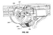
本明細書に説明されるシステム100の全ての実施形態は、インプラント102を前立腺に近接する種々の場所またはヒト解剖学的構造内の他の場所に送達するために使用されることができる。図7は、前立腺部尿道内の埋込場所の種々の実施例を説明する際の使用のための状況を提供する、男性の解剖学的構造の断面である。ここでは、前立腺1302は、中心に位置し、膀胱壁1304および膀胱1305は、上方に位置する。前立腺部尿道1306は、膀胱1305から射精管1307を過ぎて、前立腺1302を通して下方に延在する。前立腺部尿道1306は、外尿道括約筋1309の一般的場所において尿道膜性部1308になり、継続して身体から退出する。直腸は、1310によって示される。 All embodiments of the
図8Aは、後方方向がページの中に延在し、前方方向がページから外に延在するように、図7の視点から回転された断面である。ここでは、インプラント102の例示的実施形態は、前立腺部尿道1306内に位置付けられて示される。インプラント102は、概して、本視点から視認されるように前立腺部尿道1306内で中心に、言い換えると、概して、前立腺1302の上および下縁から等距離に位置付けられる。インプラント102の設置は、概して、医療専門家の判断により、ここで示される位置から上方または下方にのいずれかで、オフセットされることができるが、しかしながら、前立腺部尿道1306内の位置が、概して、好ましい。 FIG. 8A is a cross-section rotated from the perspective of FIG. 7 so that the back direction extends into the page and the front direction extends out of the page. Here, an exemplary embodiment of
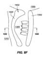
図8Bは、概して、図7のものと同一の視点からであるが、より詳細に前立腺1302の面積を描写する。ここでは、前立腺1302は、前立腺部尿道1306の中に突出する中葉1402を伴って肥大状態である。図8Cは、図8Bの線8C-8Cに沿って得られる、断面であり、尿道1306の幅が、前方側から後方側まで進むにつれて広くなる、本肥大前立腺1302内の前立腺部尿道1306のスリット様性質を示す。 FIG. 8B is generally from the same perspective as that of FIG. 7, but depicts the area of
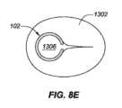
図8Dは、図8Bに関して説明される例示的解剖学的構造内の後方に設置されたインプラント102の例示的実施形態を描写し、図8Eは、図8Dの線8E-8Eに沿って得られる、断面である。ここで見られ得るように、インプラント102は、概して、前立腺部尿道1306の最後方表面に沿って設置される。インプラント102は、インプラント102が、実質的に前立腺部尿道1306の後方側上に存在し、尿道1306の最前方側と接触しないものとして説明され得るように、その最大中心幅における前立腺部尿道1306の幅未満(例えば、幅の50%未満、幅の65%未満、幅の80%未満等)である最大直径を有するように定寸される。本設置の含意は、インプラント102によって作成される前立腺1302を通した開口部が、主として前立腺1302および尿道1306の後方側上に位置付けられる、図8Eに示される。 FIG. 8D depicts an exemplary embodiment of a posteriorly placed
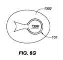
図8Fは、図8Bに関して説明される例示的解剖学的構造内の前方に設置されたインプラント102の例示的実施形態を描写し、図8Gは、図8Eの線8G-8Gに沿って得られる、断面である。ここで見られ得るように、インプラント102は、概して、前立腺部尿道1306の最前方表面に沿って設置される。インプラント102は、インプラント102が、実質的に前立腺部尿道1306の前方側上に存在し、尿道1306の最後方側と接触しないものとして説明され得るように、その最大中心幅における前立腺部尿道1306の幅未満(例えば、幅の50%未満、幅の65%未満、幅の80%未満等)である最大直径を有するように定寸されることができる。本設置の含意は、インプラント102によって作成される前立腺1302を通した開口部が、主として前立腺1302および尿道1306の前方側上に位置付けられる、図8Gに示される。後方設置および前方設置の両方を用いると、インプラント102は、依然として、図8Aに示されるように、前立腺1302に対して略中心に設置されることができる。後方または前方位置におけるインプラント102の展開は、概して、医療専門家の判断による。尿道1306の最後方側と最内側との間で中心に位置する設置、ならびにインプラント102がここで示されるよりも前立腺1302に対して比較的に大きいまたは小さい直径を有するような定寸の変形例を含む、設置の他の変形例もまた、使用されることができる。
除去方法FIG. 8F depicts an exemplary embodiment of an anteriorly placed
Removal method
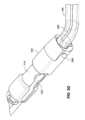
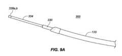
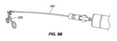
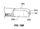
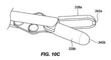
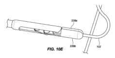
一実施形態では、インプラント102は、本デバイスの非外傷性端部を把持し、これがカテーテルの管腔を通して抜去され得るように、本デバイスをその拡張された螺旋形状から略線形形状に変形させることによって除去されることができる。送達デバイス103の外側管状部材120の管腔121を通して挿入されるように構成される、回収デバイス300は、インプラント102の急性および慢性の両方の回収のために使用されることができる。図9A-9Cに描写されるように、送達デバイス103は、インプラント102を除去するために使用されることができる。伸長可撓性管状部材330が、外側管状部材120の第1の内側管腔121を通して送達されることができる。伸長可撓性管状部材330は、ポリマー、例えば、PEEKから作製されることができる。作動シャフト334が、伸長可撓性管状部材330の管腔を通して送達されることができる。作動シャフト334は、遠位端における鉗子カップまたは対向するジョー338a、bと、近位端における対向するジョー338a、bの開放および閉鎖を操作するように構成される、作動取っ手336とを有してもよい。作動シャフト334はまた、デバイス取っ手336が関節運動されるとき、伸長可撓性管状部材330に対して軸方向に移動するように構成されてもよい。作動シャフト334の遠位端は、伸長可撓性管状部材330の遠位端を過ぎて延在されることができ、これは、外側管状部材120の遠位端を過ぎて延在され、例えば、インプラント102の丸形、球形、円筒形、円錐台状、またはボール状である非外傷性116、117のいずれかを把持することができる。対向するジョー338a、bは、閉鎖構成における対向するジョー338a、bによって画定される空洞内に非外傷性端部116、117のうちの1つを保持するように構成される。図10A-10Fに見られるように、対向するジョー338a、bはそれぞれさらに、対向するジョー338a、bが閉鎖構成にあるとき、遠位端における開口部340が形成されるように、対向するジョー338a、bの遠位領域内に曲線状縁342a、bを含んでもよく、開口部340は、閉鎖構成における対向するジョー338a、bによって画定される空洞と連通する。図11A-11Bに見られるように、いったん非外傷性端部116、117のいずれかが、把持されると、伸長可撓性管状部材330の管腔の中への関節運動シャフト334の近位抜去は、インプラントが外側管状部材120の管腔121を通して抜去され得るように、インプラント102を直線化する(すなわち、インプラントを略線形形態に引動する)結果をもたらすであろう。 In one embodiment, the
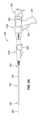
別の実施形態では、インプラントは、非外傷性端部のみを把持するのではなく、インプラントの長さに沿った任意の場所を把持することによって除去されることができる。そのような手技は、医院内外来患者手技において実施され得る。送達デバイス103の外側管状部材120の管腔121を通して挿入されるように構成される、単回使用回収デバイス400は、インプラント102の急性および慢性の両方の回収のために使用されることができる。図12に見られるように、回収デバイス400は、関節運動取っ手410と、半可撓性シース414と、遠位端に把持フック420を伴う作動シャフト418とを含む。半可撓性シース414は、増加された可撓性のために、遠位領域416内にレーザ切断パターンを伴うステンレス鋼管であってもよい。遠位領域416は、半可撓性シース414の遠位端から約3~約8インチ、代替として、約3~約7インチ、代替として、約4~約7インチ、代替として、約3~約6インチであってもよい。レーザ切断パターンは、送達デバイス103の作業長を通して使用されるとき、操縦性を可能にすることができる。半可撓性シース414内には、デバイス取っ手410が関節運動されるとき、シース410に対して軸方向に移動するように構成される、作動シャフト418がある。作動シャフト418はまた、これが送達デバイス103の作業チャネルを通して使用されるときに撓曲および操縦され得るように、半可撓性であってもよい。把持フック420は、作動シャフト418の遠位端に位置する。非外傷性把持フック420は、シース414の遠位端を越えて延在し、回収デバイス取っ手が「開」位置にあるとき、撮像デバイスを介して可視であり得る。把持フック420は、関節運動取っ手410が「閉」位置にあるとき、シース414の中に抜去および後退されることができる。 In another embodiment, the implant can be removed by grasping anywhere along the length of the implant rather than just the atraumatic end. Such procedures may be performed in an in-office outpatient procedure. Single-use retrieval device 400, configured to be inserted through
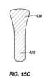
図15A-15Cに見られるように、フック420は、インプラントの可視化を可能にするように成形されてもよい。図15Cに見られるように、フックの先端428は、フックの後部部分430よりも幅狭であってもよい。フック420は、断面形状の裏側部分430が前側部分428よりも幅広い断面形状を有してもよい。フックの先端428の幅は、約0.015インチ~約0.050インチ、代替として、約0.010インチ~約0.040インチ、代替として、約0.01インチ~約0.030インチであってもよい。フックの前側部分428の幅は、裏側部分430の最も大きい幅よりも約1/3~約2/3、代替として、約1/4~約3/4、代替として、約1/2幅狭であってもよい。 As seen in FIGS. 15A-15C, the
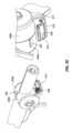
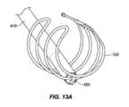
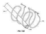
回収デバイス400のシース414は、外側管状部材120の第1の内側管腔121の中に挿入され、除去されるべきインプラント102まで操縦されることを意図している。把持フック420は、インプラント102の任意の部分を把持してもよい。例えば、把持フック420は、インプラント102の伸長ワイヤに沿った任意の場所でインプラントを把持してもよい。インプラント102は、その任意の部分が把持フック420のスロットの内側にあるときに「把持」されている(図13A-13D参照)。いったんインプラントが、把持フック420によって係合されると、ユーザは、デバイス取っ手410を関節運動させてもよい。図14に見られるように、開位置から閉位置へのデバイス取っ手410の関節運動は、インプラントの把持された部分に3点屈曲部を印加する。3点屈曲部は、把持フック420がシース414の中に抜去される際(方向Aにおける矢印参照)、シース414の外壁422によってインプラント102に印加される力(方向Bにおける矢印参照)によって引き起こされ得る。力が、デバイス取っ手に印加され、把持フックが、後退される際、インプラントは、3点屈曲部の力に起因して、効果的に圧着する。把持フック420およびインプラント102はまた、半可撓性シースの中に部分的に抜去される。本作用は、高歪みを誘発し得、これは、インプラントを恒久的に変形させ得る。いったん取っ手が、閉位置まで完全に関節運動され、インプラントが、圧着され、シース414に部分的に抜去されると、インプラント102は、管腔121から引動され、患者から除去されることができる。除去の機構は、インプラントの「二重線構造」に依拠し、圧着されたフックの各側上のワイヤは、回収デバイスがスコープ作業チャネルを通して後方に引動されるにつれて、略線形形状に直線化する。シース414は、ハイポチューブ、例えば、レーザ切断されたハイポチューブであってもよい。他の実施形態では、シース414は、シース414の遠位領域にわたって配置される、剛性部材を含んでもよく、剛性部材は、圧縮支持を有し、3点屈曲部を形成するために2つの対抗力をインプラント102に印加するために十分に剛性である。剛性部材は、形状において管状または非管状であってもよい。 Sheath 414 of retrieval device 400 is intended to be inserted into first
本明細書に説明される実施形態は、図を明示的に参照することなく、以下の段落において再び述べられ、さらに詳述される。 The embodiments described herein will be restated and further detailed in the following paragraphs without explicit reference to the figures.
多くの実施形態では、患者の尿道からインプラントを除去する方法が、説明され、本方法は、患者の尿道内の除去デバイスの一部をインプラントの近傍の位置に前進させるステップであって、除去デバイスは、外側管状部材と、外側管状部材の管腔内の内側伸長管状部材と、内側伸長管状部材の管腔内の伸長作動部材とを備え、伸長作動部材は、取っ手に結合される、近位端と、フックを備える、遠位端とを有する、ステップと、伸長作動部材の遠位端を、外側管状部材の遠位端の遠位に、かつ内側伸長管状部材の遠位端の遠位に前進させるステップと、フックを用いてインプラントの一部を把持するステップと、屈曲部がインプラントにおいて形成されるように、フックおよびインプラントの少なくとも一部を内側伸長管状部材の管腔の中に近位に抜去するステップと、外側管状部材の管腔を通してインプラントを抜去するステップであって、インプラントは、内側伸長管状部材の管腔内にある間、軸方向に伸長の形状である、ステップとを含む。 In many embodiments, a method of removing an implant from a patient's urethra is described, the method comprising: advancing a portion of a removal device within the patient's urethra to a position proximate the implant; comprises an outer tubular member, an inner elongate tubular member within the lumen of the outer tubular member, and an elongation actuation member within the lumen of the inner elongate tubular member, the elongation actuation member coupled to the handle. a step, the distal end of the elongate actuating member distal to the distal end of the outer tubular member and distal to the distal end of the inner elongate tubular member, the step having a distal end that includes an end and a hook; grasping a portion of the implant with the hook; and proximate the hook and at least a portion of the implant into the lumen of the inner elongate tubular member such that a bend is formed in the implant. and removing the implant through the lumen of the outer tubular member, the implant being in an axially elongated configuration while within the lumen of the inner elongated tubular member. include.
いくつかの実施形態では、インプラントは、第1の端部と、第2の端部と、中間部分とを有し、フックは、中間部分においてインプラントを把持する。 In some embodiments, the implant has a first end, a second end, and an intermediate portion, and the hook grasps the implant at the intermediate portion.
いくつかの実施形態では、インプラントは、伸長ワイヤと、少なくとも1つの拡大端部とを備え、フックは、伸長ワイヤを把持する。 In some embodiments, the implant includes an elongated wire and at least one enlarged end, and the hook grasps the elongated wire.
いくつかの実施形態では、内側伸長管状部材は、可撓性遠位領域を備える。いくつかの実施形態では、可撓性遠位領域は、レーザ切断された管を備える。 In some embodiments, the inner elongated tubular member includes a flexible distal region. In some embodiments, the flexible distal region comprises a laser cut tube.
いくつかの実施形態では、内側伸長管状部材は、ハイポチューブである。 In some embodiments, the inner elongated tubular member is a hypotube.
いくつかの実施形態では、除去デバイスはさらに、内側伸長管状部材の遠位領域にわたって配置される、剛性部材を含む。 In some embodiments, the removal device further includes a rigid member disposed over the distal region of the inner elongated tubular member.
いくつかの実施形態では、3点屈曲部が、インプラントにおいて形成される。 In some embodiments, a three-point bend is formed in the implant.
いくつかの実施形態では、屈曲部が、内側伸長管状部材の壁およびフックによってインプラントに印加される力の結果としてインプラントにおいて形成される。 In some embodiments, the bend is formed in the implant as a result of a force applied to the implant by the wall of the inner elongate tubular member and the hook.
いくつかの実施形態では、軸方向に伸長の形状は、インプラントの二重線構造を含む。 In some embodiments, the axially elongated shape includes a double line configuration of the implant.
いくつかの実施形態では、本方法はさらに、フックが外側管状部材の遠位端を越えて遠位に前進された後、撮像デバイスを用いてフックを視認するステップを含む。 In some embodiments, the method further includes viewing the hook using an imaging device after the hook is advanced distally beyond the distal end of the outer tubular member.
いくつかの実施形態では、フックおよびインプラントの少なくとも一部は、伸長作動部材の近位端に結合される取っ手を作動させることによって、近位に抜去される。 In some embodiments, the hook and at least a portion of the implant are proximally withdrawn by actuating a handle coupled to the proximal end of the elongate actuation member.
いくつかの実施形態では、インプラントは、拡張された螺旋形状を有する。 In some embodiments, the implant has an expanded helical shape.
いくつかの実施形態では、フックの先端は、約0.015インチ~約0.050インチの幅を有する。 In some embodiments, the tip of the hook has a width of about 0.015 inch to about 0.050 inch.
いくつかの実施形態では、フックの先端部分は、フックの後部部分よりも幅狭である。 In some embodiments, the tip portion of the hook is narrower than the rear portion of the hook.
多くの実施形態では、インプラントを回収するためのシステムが、説明され、本システムは、遠位端と、管腔とを有する、外側管状部材と、外側管状部材の管腔内の内側伸長管状部材と、内側伸長管状部材の管腔内の伸長作動部材であって、伸長作動部材は、取っ手に結合される、近位端と、フックを備える、遠位端とを有する、伸長作動部材と、内側管状部材と結合され、結合機構を通して外側管状部材と解放可能に結合される、近位制御デバイスとを含み、近位制御デバイスは、内側伸長管状部材、外側管状部材、および伸長作動部材を縦方向に移動させるように構成され、また、内側伸長管状部材の管腔内で伸長作動部材を移動させるように構成される、回収デバイスを含む。 In many embodiments, a system for retrieving an implant is described, the system comprising: an outer tubular member having a distal end and a lumen; and an inner elongated tubular member within the lumen of the outer tubular member. an elongation actuation member within the lumen of the inner elongated tubular member, the elongation actuation member having a proximal end coupled to the handle and a distal end comprising a hook; a proximal control device coupled to the inner tubular member and releasably coupled to the outer tubular member through a coupling mechanism, the proximal control device longitudinally coupling the inner elongate tubular member, the outer tubular member, and the elongate actuation member. and a retrieval device configured to move the elongate actuating member within the lumen of the inner elongate tubular member.
いくつかの実施形態では、インプラントは、第1の端部と、第2の端部と、中間部分とを有し、フックは、中間部分においてインプラントを把持するように構成される。 In some embodiments, the implant has a first end, a second end, and an intermediate portion, and the hook is configured to grasp the implant at the intermediate portion.
いくつかの実施形態では、内側伸長管状部材は、可撓性遠位領域を備える。いくつかの実施形態では、可撓性遠位領域は、レーザ切断された管を備える。 In some embodiments, the inner elongated tubular member includes a flexible distal region. In some embodiments, the flexible distal region comprises a laser cut tube.
いくつかの実施形態では、内側伸長管状部材は、ハイポチューブである。 In some embodiments, the inner elongated tubular member is a hypotube.
いくつかの実施形態では、本システムはさらに、内側伸長管状部材の遠位領域にわたって配置される、剛性部材を含む。 In some embodiments, the system further includes a rigid member disposed over a distal region of the inner elongated tubular member.
いくつかの実施形態では、外側管状部材はさらに、外側管状部材の遠位端領域内に位置する、撮像デバイスを備える。 In some embodiments, the outer tubular member further comprises an imaging device located within a distal end region of the outer tubular member.
いくつかの実施形態では、近位制御デバイスは、内側伸長管状部材、外側管状部材、および伸長作動部材を並行して縦方向に移動させるように構成される。 In some embodiments, the proximal control device is configured to longitudinally move the inner elongate tubular member, the outer tubular member, and the elongate actuation member in parallel.
いくつかの実施形態では、インプラントは、拡張された螺旋形状を有する。 In some embodiments, the implant has an expanded helical shape.
多くの実施形態では、患者の尿道からインプラントを除去する方法が、説明され、本方法は、患者の尿道内の除去デバイスをインプラントの近傍の位置に前進させるステップであって、除去デバイスは、外側管状部材と、外側管状部材の管腔内の内側伸長管状部材と、内側伸長管状部材の管腔内の伸長作動部材とを備え、伸長作動部材は、近位端と、遠位端とを備え、遠位端は、開放および閉鎖するように構成される、対向する第1および第2のジョーを備える、ステップと、伸長作動部材の遠位端を、内側伸長管状部材の遠位端の遠位に前進させるステップと、対向する第1および第2のジョーを用いてインプラントの一部を把持するステップと、内側伸長管状部材の管腔内の伸長作動部材を近位に抜去するステップであって、インプラントの少なくとも一部は、内側伸長管状部材の管腔内で軸方向に伸長の形状をとる、ステップとを含む。 In many embodiments, a method of removing an implant from a patient's urethra is described, the method comprising advancing a removal device within the patient's urethra to a position proximate to the implant, the removal device being outside the patient's urethra. a tubular member, an inner elongate tubular member within the lumen of the outer tubular member, and an elongation actuation member within the lumen of the inner elongate tubular member, the elongation actuation member comprising a proximal end and a distal end. , the distal end comprising opposed first and second jaws configured to open and close; grasping a portion of the implant using opposed first and second jaws; and proximally withdrawing the elongate actuation member within the lumen of the inner elongated tubular member. at least a portion of the implant assumes an axially elongated configuration within the lumen of the inner elongated tubular member.
いくつかの実施形態では、対向する第1および第2のジョーは、インプラントの拡大端部を把持する。いくつかの実施形態では、拡大端部の形状は、ボール、円筒、または円錐であり得る。いくつかの実施形態では、対向する第1および第2のジョーが、閉鎖構成であるとき、対向する第1および第2のジョーは、閉鎖構成の遠位端に開口部を有する。いくつかの実施形態では、インプラントは、伸長ワイヤと、少なくとも1つの拡大端部とを含み、少なくとも1つの拡大端部は、対向する第1および第2のジョーによって把持され、伸長ワイヤは、閉鎖構成の遠位端における開口部を通して延在する。 In some embodiments, opposing first and second jaws grip an enlarged end of the implant. In some embodiments, the shape of the enlarged end can be a ball, cylinder, or cone. In some embodiments, when the opposing first and second jaws are in the closed configuration, the opposing first and second jaws have openings at their distal ends in the closed configuration. In some embodiments, the implant includes an elongated wire and at least one enlarged end, the at least one enlarged end being grasped by opposing first and second jaws, and the elongated wire is closed. extending through an opening at the distal end of the arrangement.
いくつかの実施形態では、インプラントは、外側管状部材の管腔内にある間、軸方向に伸長の形状である。いくつかの実施形態では、軸方向に伸長の形状は、略線形である。 In some embodiments, the implant is in an axially elongated configuration while within the lumen of the outer tubular member. In some embodiments, the shape of the axial extension is generally linear.
いくつかの実施形態では、本方法はさらに、伸長作動部材の遠位端が外側管状部材の遠位端を越えて遠位に前進された後、撮像デバイスを用いて伸長作動部材の遠位端を視認するステップを含む。 In some embodiments, the method further includes using the imaging device to capture the distal end of the elongation actuation member after the distal end of the elongation actuation member is advanced distally beyond the distal end of the outer tubular member. including the step of visually recognizing the
いくつかの実施形態では、インプラントは、拡張された螺旋形状を有する。 In some embodiments, the implant has an expanded helical shape.
いくつかの実施形態では、フックの先端は、約0.015インチ~約0.050インチの幅を有する。 In some embodiments, the tip of the hook has a width of about 0.015 inch to about 0.050 inch.
いくつかの実施形態では、フックの先端部分は、フックの後部部分よりも幅狭である。 In some embodiments, the tip portion of the hook is narrower than the rear portion of the hook.
多くの実施形態では、インプラントを回収するためのシステムが、説明され、本システムは、遠位端と、管腔とを有する、外側管状部材と、外側管状部材の管腔内の内側伸長管状部材と、内側伸長管状部材の管腔内の伸長作動部材であって、伸長作動部材は、近位端と、遠位端とを備え、遠位端は、開放および閉鎖するように構成される、第1および第2のジョーを備える、伸長作動部材と、伸長作動部材および内側伸長管状部材と結合され、結合機構を通して外側管状部材と解放可能に結合される、近位制御デバイスとを含み、近位制御デバイスは、伸長作動部材、内側伸長管状部材、および外側管状部材を縦方向に移動させるように構成され、また、内側管状部材の管腔内で伸長作動部材を縦方向に移動させるように構成される、回収デバイスを含む。 In many embodiments, a system for retrieving an implant is described, the system comprising: an outer tubular member having a distal end and a lumen; and an inner elongated tubular member within the lumen of the outer tubular member. and an elongation actuation member within the lumen of the inner elongated tubular member, the elongation actuation member comprising a proximal end and a distal end, the distal end being configured to open and close. a proximal control device coupled to the extension actuation member and the inner elongate tubular member and releasably coupled to the outer tubular member through a coupling mechanism; The position control device is configured to longitudinally move the elongation actuation member, the inner elongate tubular member, and the outer tubular member, and is configured to longitudinally move the elongation actuation member within the lumen of the inner tubular member. comprising a retrieval device.
いくつかの実施形態では、インプラントは、第1の端部と、第2の端部と、中間部分とを有し、第1および第2の端部のうちの少なくとも1つは、拡大非外傷性端部である。いくつかの実施形態では、対向する第1および第2のジョーは、インプラントの拡大非外傷性端部を把持するように構成される。 In some embodiments, the implant has a first end, a second end, and an intermediate portion, and at least one of the first and second ends has an expanded atraumatic It is a sexual end. In some embodiments, the opposing first and second jaws are configured to grasp the enlarged atraumatic end of the implant.
いくつかの実施形態では、対向する第1および第2のジョーは、閉鎖構成にあるとき、閉鎖構成の遠位端に開口部を有する。いくつかの実施形態では、インプラントは、伸長ワイヤと、少なくとも1つの拡大端部とを備え、対向する第1および第2のジョーは、少なくとも1つの拡大端部を把持するように構成され、閉鎖構成の遠位端における開口部は、伸長ワイヤがそれを通して延在するために構成される。 In some embodiments, the opposing first and second jaws have openings at the distal ends of the closed configuration when in the closed configuration. In some embodiments, the implant includes an elongated wire and at least one enlarged end, and the opposing first and second jaws are configured to grasp the at least one enlarged end and close the implant. An opening at the distal end of the arrangement is configured for the extension wire to extend therethrough.
いくつかの実施形態では、外側管状部材はさらに、外側管状部材の遠位端領域内に位置する、撮像デバイスを備える。 In some embodiments, the outer tubular member further comprises an imaging device located within a distal end region of the outer tubular member.
いくつかの実施形態では、近位制御デバイスは、伸長部材、内側伸長部材、および外側管状部材を並行して縦方向に移動させるように構成される。 In some embodiments, the proximal control device is configured to longitudinally move the elongate member, the inner elongate member, and the outer tubular member in parallel.
いくつかの実施形態では、インプラントは、拡張された螺旋形状を有する。 In some embodiments, the implant has an expanded helical shape.
多くの実施形態では、患者の尿道からインプラントを除去する方法が、説明され、本方法は、患者の尿道内の除去デバイスをインプラントの近傍の位置に前進させるステップであって、除去デバイスは、外側管状部材と、外側管状部材の管腔内の内側伸長管状部材と、内側伸長管状部材の管腔内の伸長作動部材とを備え、伸長作動部材は、近位端と、遠位端とを備え、遠位端は、把持器を備える、ステップと、伸長作動部材の遠位端を、内側伸長管状部材の遠位端の遠位に前進させるステップと、把持器を用いてインプラントの一部を握持するステップと、内側伸長管状部材の管腔内の伸長作動部材を近位に抜去するステップであって、インプラントの少なくとも一部は、内側伸長管状部材の管腔内で軸方向に伸長の形状をとる、ステップとを含む。 In many embodiments, a method of removing an implant from a patient's urethra is described, the method comprising advancing a removal device within the patient's urethra to a position proximate to the implant, the removal device being outside the patient's urethra. a tubular member, an inner elongate tubular member within the lumen of the outer tubular member, and an elongation actuation member within the lumen of the inner elongate tubular member, the elongation actuation member comprising a proximal end and a distal end. , the distal end includes a grasper, and advancing the distal end of the elongated actuating member distally of the distal end of the inner elongated tubular member; and using the grasper to secure a portion of the implant. grasping and proximally withdrawing the elongation actuation member within the lumen of the inner elongate tubular member, the at least a portion of the implant being axially elongated within the lumen of the inner elongate tubular member. taking a shape.
いくつかの実施形態では、把持器は、対向する第1および第2のジョーを備える。いくつかの実施形態では、対向する第1および第2のジョーは、インプラントの拡大端部を握持する。いくつかの実施形態では、対向する第1および第2のジョーが、閉鎖構成であるとき、対向する第1および第2のジョーは、閉鎖構成の遠位端に開口部を有する。いくつかの実施形態では、インプラントは、伸長ワイヤと、少なくとも1つの拡大端部とを備え、少なくとも1つの拡大端部は、対向する第1および第2のジョーによって握持され、伸長ワイヤは、閉鎖構成の遠位端における開口部を通して延在する。いくつかの実施形態では、軸方向に伸長の形状は、略線形である。 In some embodiments, the grasper includes opposed first and second jaws. In some embodiments, opposing first and second jaws grip the enlarged end of the implant. In some embodiments, when the opposing first and second jaws are in the closed configuration, the opposing first and second jaws have openings at their distal ends in the closed configuration. In some embodiments, the implant comprises an elongated wire and at least one enlarged end, the at least one enlarged end being grasped by opposing first and second jaws, and the elongated wire is extending through an opening at the distal end of the closed configuration. In some embodiments, the shape of the axial extension is generally linear.
いくつかの実施形態では、把持器は、フックを備える。いくつかの実施形態では、インプラントは、第1の端部と、第2の端部と、中間部分とを有し、フックは、中間部分においてインプラントを把持する。いくつかの実施形態では、インプラントは、伸長ワイヤと、少なくとも1つの拡大端部とを備え、フックは、伸長ワイヤを把持する。いくつかの実施形態では、内側伸長管状部材は、可撓性遠位領域を備える。いくつかの実施形態では、可撓性遠位領域は、レーザ切断された管を備える。いくつかの実施形態では、内側伸長管状部材は、ハイポチューブである。いくつかの実施形態では、除去デバイスはさらに、内側伸長管状部材の遠位領域にわたって配置される、剛性部材を含む。いくつかの実施形態では、フックおよびインプラントの一部が、内側伸長管状部材の管腔内で近位に抜去されると、屈曲部が、インプラントにおいて形成される。いくつかの実施形態では、屈曲部は、3点屈曲部である。いくつかの実施形態では、屈曲部は、内側伸長管状部材の壁およびフックによってインプラントに印加される複数の力の結果としてインプラントにおいて形成される。いくつかの実施形態では、軸方向に伸長の形状は、インプラントの二重線構造を含む。いくつかの実施形態では、本方法はさらに、フックが外側管状部材の遠位端を越えて遠位に前進された後、撮像デバイスを用いてフックを視認するステップを含む。 In some embodiments, the grasper comprises a hook. In some embodiments, the implant has a first end, a second end, and an intermediate portion, and the hook grasps the implant at the intermediate portion. In some embodiments, the implant includes an elongated wire and at least one enlarged end, and the hook grasps the elongated wire. In some embodiments, the inner elongated tubular member includes a flexible distal region. In some embodiments, the flexible distal region comprises a laser cut tube. In some embodiments, the inner elongated tubular member is a hypotube. In some embodiments, the removal device further includes a rigid member disposed over the distal region of the inner elongated tubular member. In some embodiments, a bend is formed in the implant when the hook and a portion of the implant are withdrawn proximally within the lumen of the inner elongated tubular member. In some embodiments, the bend is a three-point bend. In some embodiments, the bend is formed in the implant as a result of forces applied to the implant by the wall of the inner elongated tubular member and the hook. In some embodiments, the axially elongated shape includes a double line configuration of the implant. In some embodiments, the method further includes viewing the hook using an imaging device after the hook is advanced distally beyond the distal end of the outer tubular member.
いくつかの実施形態では、インプラントは、拡張された螺旋形状を有する。 In some embodiments, the implant has an expanded helical shape.
いくつかの実施形態では、フックの先端は、約0.015インチ~約0.050インチの幅を有する。 In some embodiments, the tip of the hook has a width of about 0.015 inch to about 0.050 inch.
いくつかの実施形態では、フックの先端部分は、フックの後部部分よりも幅狭である。 In some embodiments, the tip portion of the hook is narrower than the rear portion of the hook.
多くの実施形態では、インプラントを回収するためのシステムが、説明され、本システムは、遠位端と、管腔とを有する、外側管状部材と、外側管状部材の管腔内の内側伸長管状部材と、内側伸長管状部材の管腔内の伸長作動部材であって、伸長作動部材は、近位端と、遠位端とを備え、遠位端は、把持器を備える、伸長作動部材と、伸長作動部材および内側伸長作動部材と結合され、結合機構を通して外側管状部材と解放可能に結合される、近位制御デバイスとを含み、近位制御デバイスは、伸長作動部材、内側伸長管状部材、および外側管状部材を縦方向に移動させるように構成され、また、内側管状部材の管腔内で伸長作動部材を縦方向に移動させるように構成される、回収デバイスを含む。 In many embodiments, a system for retrieving an implant is described, the system comprising: an outer tubular member having a distal end and a lumen; and an inner elongated tubular member within the lumen of the outer tubular member. an elongation actuation member within the lumen of the inner elongated tubular member, the elongation actuation member comprising a proximal end and a distal end, the distal end comprising a grasper; a proximal control device coupled to the elongation actuation member and the inner elongation actuation member and releasably coupled to the outer tubular member through a coupling mechanism, the proximal control device including the elongation actuation member, the inner elongation tubular member, and A retrieval device configured to longitudinally move the outer tubular member and configured to longitudinally move an elongate actuation member within the lumen of the inner tubular member.
いくつかの実施形態では、把持器は、対向する第1および第2のジョーを備える。いくつかの実施形態では、インプラントは、第1の端部と、第2の端部と、中間部分とを有し、第1および第2の端部のうちの少なくとも1つは、拡大非外傷性端部である。いくつかの実施形態では、対向する第1および第2のジョーは、インプラントの拡大非外傷性端部を把持するように構成される。いくつかの実施形態では、対向する第1および第2のジョーは、閉鎖構成にあるとき、閉鎖構成の遠位端に開口部を有する。いくつかの実施形態では、インプラントは、伸長ワイヤと、少なくとも1つの拡大端部とを備え、対向する第1および第2のジョーは、少なくとも1つの拡大端部を把持するように構成され、閉鎖構成の遠位端における開口部は、伸長ワイヤがそれを通して延在するために構成される。 In some embodiments, the grasper includes opposed first and second jaws. In some embodiments, the implant has a first end, a second end, and an intermediate portion, and at least one of the first and second ends has an expanded atraumatic It is a sexual end. In some embodiments, the opposing first and second jaws are configured to grasp the enlarged atraumatic end of the implant. In some embodiments, the opposing first and second jaws have openings at the distal ends of the closed configuration when in the closed configuration. In some embodiments, the implant includes an elongated wire and at least one enlarged end, and the opposing first and second jaws are configured to grasp the at least one enlarged end and close the implant. An opening at the distal end of the arrangement is configured for the extension wire to extend therethrough.
いくつかの実施形態では、外側管状部材はさらに、外側管状部材の遠位端領域内に位置する、撮像デバイスを備える。 In some embodiments, the outer tubular member further comprises an imaging device located within a distal end region of the outer tubular member.
いくつかの実施形態では、近位制御デバイスは、伸長部材、内側伸長部材、および外側管状部材を並行して縦方向に移動させるように構成される。 In some embodiments, the proximal control device is configured to longitudinally move the elongate member, the inner elongate member, and the outer tubular member in parallel.
いくつかの実施形態では、把持器は、フックを備える。いくつかの実施形態では、インプラントは、第1の端部と、第2の端部と、中間部分とを有し、フックは、中間部分においてインプラントを把持するように構成される。いくつかの実施形態では、内側伸長管状部材は、可撓性遠位領域を備える。いくつかの実施形態では、内側伸長管状部材は、ハイポチューブである。いくつかの実施形態では、本システムはさらに、内側伸長管状部材の遠位領域にわたって配置される、剛性部材を含む。いくつかの実施形態では、可撓性遠位領域は、レーザ切断された管を備える。いくつかの実施形態では、インプラントは、拡張された螺旋形状を有する。いくつかの実施形態では、フックの先端は、約0.015インチ~約0.050インチの幅を有する。いくつかの実施形態では、フックの先端部分は、フックの後部部分よりも幅狭である。 In some embodiments, the grasper comprises a hook. In some embodiments, the implant has a first end, a second end, and an intermediate portion, and the hook is configured to grasp the implant at the intermediate portion. In some embodiments, the inner elongated tubular member includes a flexible distal region. In some embodiments, the inner elongated tubular member is a hypotube. In some embodiments, the system further includes a rigid member disposed over a distal region of the inner elongated tubular member. In some embodiments, the flexible distal region comprises a laser cut tube. In some embodiments, the implant has an expanded helical shape. In some embodiments, the tip of the hook has a width of about 0.015 inch to about 0.050 inch. In some embodiments, the tip portion of the hook is narrower than the rear portion of the hook.
前立腺部尿道からのインプラントの回収のためのシステム、デバイス、および方法が、提供される。回収システムの実施形態は、患者の中への挿入のためのデバイスと、インプラントの一部を把持し、回収システムの管腔の中にインプラントを抜去する際の使用のための近位制御デバイスとを含むことができる。 Systems, devices, and methods are provided for retrieval of implants from the prostatic urethra. Embodiments of the retrieval system include a device for insertion into a patient and a proximal control device for grasping a portion of the implant and for use in withdrawing the implant into a lumen of the retrieval system. can include.
本発明の側面は、独立請求項に記載され、好ましい特徴は、従属請求項に記載される。各側面の好ましい特徴は、特定の実施形態内で相互と組み合わせて提供されてもよく、また、他の側面と組み合わせて提供されてもよい。
付記Aspects of the invention are set out in the independent claims and preferred features are set out in the dependent claims. Preferred features of each aspect may be provided in combination with each other and with other aspects within a particular embodiment.
Additional notes
例示的実施形態が、以下の付番された付記に記載される。
付記1.患者の尿道からインプラントを除去する方法であって、患者の尿道内の除去デバイスの一部をインプラントの近傍の位置に前進させるステップであって、除去デバイスは、外側管状部材と、外側管状部材の管腔内の内側伸長管状部材と、内側伸長管状部材の管腔内の伸長作動部材とを備え、伸長作動部材は、取っ手に結合される、近位端と、フックを備える、遠位端とを有する、ステップと、伸長作動部材の遠位端を、外側管状部材の遠位端の遠位に、かつ内側伸長管状部材の遠位端の遠位に前進させるステップと、フックを用いてインプラントの一部を把持するステップと、屈曲部がインプラントにおいて形成されるように、フックおよびインプラントの少なくとも一部を内側伸長管状部材の管腔の中に近位に抜去するステップと、外側管状部材の管腔を通してインプラントを抜去するステップであって、インプラントは、内側伸長管状部材の管腔内にある間、軸方向に伸長の形状である、ステップとを含む、方法。
付記2.インプラントは、第1の端部と、第2の端部と、中間部分とを有し、フックは、中間部分においてインプラントを把持する、付記1に記載の方法。
付記3.インプラントは、伸長ワイヤと、少なくとも1つの拡大端部とを備え、フックは、伸長ワイヤを把持する、付記1に記載の方法。
付記4.内側伸長管状部材は、可撓性遠位領域を備える、付記1に記載の方法。
付記5.可撓性遠位領域は、レーザ切断された管を備える、付記4に記載の方法。
付記6.内側伸長管状部材は、ハイポチューブである、付記1に記載の方法。
付記7.除去デバイスはさらに、内側伸長管状部材の遠位領域にわたって配置される、剛性部材を備える、付記1に記載の方法。
付記8.3点屈曲部が、インプラントにおいて形成される、付記1に記載の方法。
付記9.屈曲部が、内側伸長管状部材の壁およびフックによってインプラントに印加される力の結果としてインプラントにおいて形成される、付記1に記載の方法。
付記10.軸方向に伸長の形状は、インプラントの二重線構造を含む、付記1に記載の方法。
付記11.フックが外側管状部材の遠位端を越えて遠位に前進された後、撮像デバイスを用いてフックを視認するステップをさらに含む、付記1に記載の方法。
付記12.フックおよびインプラントの少なくとも一部は、伸長作動部材の近位端に結合される取っ手を作動させることによって、近位に抜去される、付記1に記載の方法。
付記13.インプラントは、拡張された螺旋形状を有する、付記1に記載の方法。
付記14.フックの先端は、約0.015インチ~約0.050インチの幅を有する、付記1に記載の方法。
付記15.フックの先端部分は、フックの後部部分よりも幅狭である、付記1に記載の方法。
付記16.インプラントを回収するためのシステムであって、遠位端と、管腔とを有する、外側管状部材と、外側管状部材の管腔内の内側伸長管状部材と、内側伸長管状部材の管腔内の伸長作動部材であって、伸長作動部材は、取っ手に結合される、近位端と、フックを備える、遠位端とを有する、伸長作動部材と、内側管状部材と結合され、結合機構を通して外側管状部材と解放可能に結合される、近位制御デバイスとを備え、近位制御デバイスは、内側伸長管状部材、外側管状部材、および伸長作動部材を縦方向に移動させるように構成され、また、内側伸長管状部材の管腔内で伸長作動部材を移動させるように構成される、回収デバイスを備える、システム。
付記17.インプラントは、第1の端部と、第2の端部と、中間部分とを有し、フックは、中間部分においてインプラントを把持するように構成される、付記16に記載のシステム。
付記18.内側伸長管状部材は、可撓性遠位領域を備える、付記16に記載のシステム。
付記19.内側伸長管状部材は、ハイポチューブである、付記16に記載のシステム。
付記20.本システムはさらに、内側伸長管状部材の遠位領域にわたって配置される、剛性部材を備える、付記16に記載のシステム。
付記21.可撓性遠位領域は、レーザ切断された管を備える、付記18に記載のシステム。
付記22.外側管状部材はさらに、外側管状部材の遠位端領域内に位置する、撮像デバイスを備える、付記16に記載のシステム。
付記23.近位制御デバイスは、内側伸長管状部材、外側管状部材、および伸長作動部材を並行して縦方向に移動させるように構成される、付記16に記載のシステム。
付記24.インプラントは、拡張された螺旋形状を有する、付記16に記載のシステム。
付記25.フックの先端は、約0.015インチ~約0.050インチの幅を有する、付記16に記載のシステム。
付記26.フックの先端部分は、フックの後部部分よりも幅狭である、付記16に記載のシステム。
付記27.患者の尿道からインプラントを除去する方法であって、患者の尿道内の除去デバイスをインプラントの近傍の位置に前進させるステップであって、除去デバイスは、外側管状部材と、外側管状部材の管腔内の内側伸長管状部材と、内側伸長管状部材の管腔内の伸長作動部材とを備え、伸長作動部材は、近位端と、遠位端とを備え、遠位端は、開放および閉鎖するように構成される、対向する第1および第2のジョーを備える、ステップと、伸長作動部材の遠位端を、内側伸長管状部材の遠位端の遠位に前進させるステップと、対向する第1および第2のジョーを用いてインプラントの一部を把持するステップと、内側伸長管状部材の管腔内の伸長作動部材を近位に抜去するステップであって、インプラントの少なくとも一部は、内側伸長管状部材の管腔内で軸方向に伸長の形状をとる、ステップとを含む、方法。
付記28.対向する第1および第2のジョーは、インプラントの拡大端部を把持する、付記27に記載の方法。
付記29.拡大端部は、ボール、円筒、および円錐から成る群から選択される形状である、付記28に記載の方法。
付記30.対向する第1および第2のジョーが、閉鎖構成であるとき、対向する第1および第2のジョーは、閉鎖構成の遠位端に開口部を有する、付記28に記載の方法。
付記31.インプラントは、伸長ワイヤと、少なくとも1つの拡大端部とを備え、少なくとも1つの拡大端部は、対向する第1および第2のジョーによって把持され、伸長ワイヤは、閉鎖構成の遠位端における開口部を通して延在する、付記30に記載の方法。
付記32.インプラントは、外側管状部材の管腔内にある間、軸方向に伸長の形状である、付記27に記載の方法。
付記33.軸方向に伸長の形状は、略線形である、付記32に記載の方法。
付記34.伸長作動部材の遠位端が外側管状部材の遠位端を越えて遠位に前進された後、撮像デバイスを用いて伸長作動部材の遠位端を視認するステップをさらに含む、付記27に記載の方法。
付記35.インプラントは、拡張された螺旋形状を有する、付記27に記載の方法。
付記36.インプラントを回収するためのシステムであって、遠位端と、管腔とを有する、外側管状部材と、外側管状部材の管腔内の内側伸長管状部材と、内側伸長管状部材の管腔内の伸長作動部材であって、伸長作動部材は、近位端と、遠位端とを備え、遠位端は、開放および閉鎖するように構成される、第1および第2のジョーを備える、伸長作動部材と、伸長作動部材および内側伸長管状部材と結合され、結合機構を通して外側管状部材と解放可能に結合される、近位制御デバイスとを備え、近位制御デバイスは、伸長作動部材、内側伸長管状部材、および外側管状部材を縦方向に移動させるように構成され、また、内側管状部材の管腔内で伸長作動部材を縦方向に移動させるように構成される、回収デバイスを備える、システム。
付記37.インプラントは、第1の端部と、第2の端部と、中間部分とを有し、第1および第2の端部のうちの少なくとも1つは、拡大非外傷性端部である、付記36に記載のシステム。
付記38.対向する第1および第2のジョーは、インプラントの拡大非外傷性端部を把持するように構成される、付記37に記載のシステム。
付記39.対向する第1および第2のジョーは、閉鎖構成にあるとき、閉鎖構成の遠位端に開口部を有する、付記36に記載のシステム。
付記40.インプラントは、伸長ワイヤと、少なくとも1つの拡大端部とを備え、対向する第1および第2のジョーは、少なくとも1つの拡大端部を把持するように構成され、閉鎖構成の遠位端における開口部は、伸長ワイヤがそれを通して延在するために構成される、付記39に記載のシステム。
付記41.外側管状部材はさらに、外側管状部材の遠位端領域内に位置する、撮像デバイスを備える、付記36に記載のシステム。
付記42.近位制御デバイスは、伸長部材、内側伸長部材、および外側管状部材を並行して縦方向に移動させるように構成される、付記36に記載のシステム。
付記43.インプラントは、拡張された螺旋形状を有する、付記36に記載のシステム。
付記44.患者の尿道からインプラントを除去する方法であって、患者の尿道内の除去デバイスをインプラントの近傍の位置に前進させるステップであって、除去デバイスは、外側管状部材と、外側管状部材の管腔内の内側伸長管状部材と、内側伸長管状部材の管腔内の伸長作動部材とを備え、伸長作動部材は、近位端と、遠位端とを備え、遠位端は、把持器を備える、ステップと、伸長作動部材の遠位端を、内側伸長管状部材の遠位端の遠位に前進させるステップと、把持器を用いてインプラントの一部を握持するステップと、内側伸長管状部材の管腔内の伸長作動部材を近位に抜去するステップであって、インプラントの少なくとも一部は、内側伸長管状部材の管腔内で軸方向に伸長の形状をとる、ステップとを含む、方法。
付記45.把持器は、対向する第1および第2のジョーを備える、付記44に記載の方法。
付記46.対向する第1および第2のジョーは、インプラントの拡大端部を握持する、付記45に記載の方法。
付記47.対向する第1および第2のジョーが、閉鎖構成であるとき、対向する第1および第2のジョーは、閉鎖構成の遠位端に開口部を有する、付記45に記載の方法。
付記48.インプラントは、伸長ワイヤと、少なくとも1つの拡大端部とを備え、少なくとも1つの拡大端部は、対向する第1および第2のジョーによって握持され、伸長ワイヤは、閉鎖構成の遠位端における開口部を通して延在する、付記47に記載の方法。
付記49.軸方向に伸長の形状は、略線形である、付記45に記載の方法。
付記50.把持器は、フックを備える、付記44に記載の方法。
付記51.インプラントは、第1の端部と、第2の端部と、中間部分とを有し、フックは、中間部分においてインプラントを把持する、付記50に記載の方法。
付記52.インプラントは、伸長ワイヤと、少なくとも1つの拡大端部とを備え、フックは、伸長ワイヤを把持する、付記50に記載の方法。
付記53.フックの先端は、約0.015インチ~約0.050インチの幅を有する、付記50に記載の方法。
付記54.フックの先端部分は、フックの後部部分よりも幅狭である、付記50に記載の方法。
付記55.内側伸長管状部材は、可撓性遠位領域を備える、付記50に記載の方法。
付記56.可撓性遠位領域は、レーザ切断された管を備える、付記55に記載の方法。
付記57.内側伸長管状部材は、ハイポチューブである、付記50に記載の方法。
付記58.除去デバイスはさらに、内側伸長管状部材の遠位領域にわたって配置される、剛性部材を備える、付記50に記載の方法。
付記59.フックおよびインプラントの一部が、内側伸長管状部材の管腔内で近位に抜去されると、屈曲部が、インプラントにおいて形成される、付記50に記載の方法。
付記60.屈曲部は、3点屈曲部である、付記59に記載の方法。
付記61.屈曲部は、内側伸長管状部材の壁およびフックによってインプラントに印加される複数の力の結果としてインプラントにおいて形成される、付記59に記載の方法。
付記62.軸方向に伸長の形状は、インプラントの二重線構造を含む、付記50に記載の方法。
付記63.フックが外側管状部材の遠位端を越えて遠位に前進された後、撮像デバイスを用いてフックを視認するステップをさらに含む、付記50に記載の方法。
付記64.インプラントは、拡張された螺旋形状を有する、付記44に記載の方法。
付記65.インプラントを回収するためのシステムであって、遠位端と、管腔とを有する、外側管状部材と、外側管状部材の管腔内の内側伸長管状部材と、内側伸長管状部材の管腔内の伸長作動部材であって、伸長作動部材は、近位端と、遠位端とを備え、遠位端は、把持器を備える、伸長作動部材と、伸長作動部材および内側伸長作動部材と結合され、結合機構を通して外側管状部材と解放可能に結合される、近位制御デバイスとを備え、近位制御デバイスは、伸長作動部材、内側伸長管状部材、および外側管状部材を縦方向に移動させるように構成され、また、内側管状部材の管腔内で伸長作動部材を縦方向に移動させるように構成される、回収デバイスを備える、システム。
付記66.把持器は、対向する第1および第2のジョーを備える、付記65に記載のシステム。
付記67.インプラントは、第1の端部と、第2の端部と、中間部分とを有し、第1および第2の端部のうちの少なくとも1つは、拡大非外傷性端部である、付記66に記載のシステム。
付記68.対向する第1および第2のジョーは、インプラントの拡大非外傷性端部を把持するように構成される、付記67に記載のシステム。
付記69.対向する第1および第2のジョーは、閉鎖構成にあるとき、閉鎖構成の遠位端に開口部を有する、付記66に記載のシステム。
付記70.インプラントは、伸長ワイヤと、少なくとも1つの拡大端部とを備え、対向する第1および第2のジョーは、少なくとも1つの拡大端部を把持するように構成され、閉鎖構成の遠位端における開口部は、伸長ワイヤがそれを通して延在するために構成される、付記69に記載のシステム。
付記71.外側管状部材はさらに、外側管状部材の遠位端領域内に位置する、撮像デバイスを備える、付記65に記載のシステム。
付記72.近位制御デバイスは、伸長部材、内側伸長部材、および外側管状部材を並行して縦方向に移動させるように構成される、付記65に記載のシステム。
付記73.把持器は、フックを備える、付記65に記載のシステム。
付記74.インプラントは、第1の端部と、第2の端部と、中間部分とを有し、フックは、中間部分においてインプラントを把持するように構成される、付記73に記載のシステム。
付記75.フックの先端は、約0.015インチ~約0.050インチの幅を有する、付記73に記載のシステム。
付記76.フックの先端部分は、フックの後部部分よりも幅狭である、付記73に記載のシステム。
付記77.内側伸長管状部材は、可撓性遠位領域を備える、付記73に記載のシステム。
付記78.可撓性遠位領域は、レーザ切断された管を備える、付記77に記載のシステム。
付記79.内側伸長管状部材は、ハイポチューブである、付記73に記載のシステム。
付記80.本システムはさらに、内側伸長管状部材の遠位領域にわたって配置される、剛性部材を備える、付記73に記載のシステム。
付記81.インプラントは、拡張された螺旋形状を有する、付記65に記載のシステム。Exemplary embodiments are described in the numbered appendices below.
Additional note 1. A method of removing an implant from a patient's urethra, the method comprising: advancing a portion of a removal device within the patient's urethra to a position proximate the implant, the removal device comprising: an outer tubular member; an inner elongate tubular member within the lumen and an elongation actuation member within the lumen of the inner elongate tubular member, the elongation actuation member having a proximal end coupled to the handle, a distal end comprising a hook; advancing the distal end of the elongate actuating member distally of the distal end of the outer tubular member and distal of the distal end of the inner elongate tubular member; and withdrawing the hook and at least a portion of the implant proximally into the lumen of the inner elongated tubular member such that a bend is formed in the implant; removing the implant through the lumen, the implant being in an axially elongated configuration while within the lumen of the inner elongated tubular member.
Appendix 3. 10. The method of clause 1, wherein the implant comprises an elongated wire and at least one enlarged end, and the hook grasps the elongated wire.
Appendix 4. 10. The method of clause 1, wherein the inner elongated tubular member comprises a flexible distal region.
Appendix 5. 5. The method of clause 4, wherein the flexible distal region comprises a laser cut tube.
Appendix 6. The method of clause 1, wherein the inner elongated tubular member is a hypotube.
Appendix 7. 10. The method of clause 1, wherein the removal device further comprises a rigid member disposed over a distal region of the inner elongate tubular member.
Appendix 9. 10. The method of claim 1, wherein the bend is formed in the implant as a result of a force applied to the implant by the wall of the inner elongated tubular member and the hook.
Appendix 10. 10. The method of claim 1, wherein the axially elongated shape comprises a double line configuration of the implant.
Appendix 11. The method of clause 1, further comprising visualizing the hook using an imaging device after the hook is advanced distally beyond the distal end of the outer tubular member.
Appendix 12. 10. The method of clause 1, wherein at least a portion of the hook and the implant are proximally withdrawn by actuating a handle coupled to the proximal end of the elongated actuation member.
Appendix 13. The method of clause 1, wherein the implant has an expanded helical shape.
Appendix 14. The method of clause 1, wherein the tip of the hook has a width of about 0.015 inch to about 0.050 inch.
Appendix 15. The method of claim 1, wherein the tip portion of the hook is narrower than the rear portion of the hook.
Appendix 16. A system for retrieving an implant, the system comprising: an outer tubular member having a distal end and a lumen; an inner elongated tubular member within the lumen of the inner elongated tubular member; an elongation actuation member, the elongation actuation member having a proximal end coupled to the handle and a distal end comprising a hook; the elongation actuation member coupled to the inner tubular member; the elongation actuation member coupled to the inner tubular member; a proximal control device releasably coupled to the tubular member, the proximal control device configured to longitudinally move the inner elongate tubular member, the outer tubular member, and the elongate actuation member; A system comprising a retrieval device configured to move an elongated actuation member within a lumen of an inner elongated tubular member.
Appendix 17. 17. The system of clause 16, wherein the implant has a first end, a second end, and an intermediate portion, and the hook is configured to grasp the implant at the intermediate portion.
Appendix 18. 17. The system of clause 16, wherein the inner elongate tubular member comprises a flexible distal region.
Appendix 19. 17. The system of clause 16, wherein the inner elongated tubular member is a hypotube.
Appendix 20. 17. The system of clause 16, further comprising a rigid member disposed over a distal region of the inner elongate tubular member.
Appendix 21. 19. The system of clause 18, wherein the flexible distal region comprises a laser cut tube.
Appendix 22. 17. The system of clause 16, wherein the outer tubular member further comprises an imaging device located within a distal end region of the outer tubular member.
Appendix 23. 17. The system of clause 16, wherein the proximal control device is configured to longitudinally move the inner elongated tubular member, the outer tubular member, and the elongated actuation member in parallel.
Appendix 24. 17. The system of clause 16, wherein the implant has an expanded helical shape.
Appendix 25. 17. The system of clause 16, wherein the tip of the hook has a width of about 0.015 inches to about 0.050 inches.
Appendix 26. 17. The system of clause 16, wherein the tip portion of the hook is narrower than the rear portion of the hook.
Appendix 27. A method of removing an implant from a patient's urethra, the method comprising: advancing a removal device within the patient's urethra to a position proximate the implant, the removal device having an outer tubular member and a lumen of the outer tubular member. an elongate inner tubular member and an elongate actuation member within the lumen of the inner elongate tubular member, the elongation actuation member having a proximal end and a distal end, the distal end being adapted to open and close. advancing the distal end of the elongate actuating member distally of the distal end of the inner elongate tubular member; and grasping a portion of the implant with a second jaw; and proximally withdrawing the elongation actuating member within the lumen of the inner elongate tubular member, the at least a portion of the implant and assuming an axially elongated configuration within the lumen of the tubular member.
Appendix 28. 28. The method of clause 27, wherein the opposing first and second jaws grip an enlarged end of the implant.
Appendix 29. 29. The method of clause 28, wherein the enlarged end is a shape selected from the group consisting of a ball, a cylinder, and a cone.
Appendix 30. 29. The method of clause 28, when the opposing first and second jaws are in the closed configuration, the opposing first and second jaws have openings at their distal ends in the closed configuration.
Appendix 31. The implant includes an elongate wire and at least one enlarged end, the at least one enlarged end being gripped by opposing first and second jaws, the elongate wire extending through an opening at the distal end in a closed configuration. The method of claim 30, extending through the section.
Appendix 32. 28. The method of clause 27, wherein the implant is in an axially elongated configuration while within the lumen of the outer tubular member.
Appendix 33. 33. The method according to appendix 32, wherein the axially elongated shape is substantially linear.
Appendix 34. Claim 27, further comprising viewing the distal end of the elongation actuation member using an imaging device after the distal end of the elongation actuation member is advanced distally beyond the distal end of the outer tubular member. the method of.
Appendix 35. 28. The method of clause 27, wherein the implant has an expanded helical shape.
Appendix 36. A system for retrieving an implant, the system comprising: an outer tubular member having a distal end and a lumen; an inner elongated tubular member within the lumen of the inner elongated tubular member; an elongation actuation member, the elongation actuation member comprising a proximal end and a distal end, the distal end comprising first and second jaws configured to open and close; an actuation member; a proximal control device coupled to the elongate actuation member and the inner elongate tubular member and releasably coupled to the outer tubular member through a coupling mechanism, the proximal control device being coupled to the elongate actuator member, the inner elongate tubular member; A system comprising: a tubular member; and a retrieval device configured to longitudinally move the outer tubular member and configured to longitudinally move an elongated actuation member within the lumen of the inner tubular member.
Appendix 37. The implant has a first end, a second end, and an intermediate portion, and at least one of the first and second ends is an enlarged atraumatic end. 36. The system according to 36.
Appendix 38. 38. The system of clause 37, wherein the opposing first and second jaws are configured to grasp the enlarged atraumatic end of the implant.
Appendix 39. 37. The system of clause 36, wherein the opposing first and second jaws have an opening at a distal end of the closed configuration when in the closed configuration.
Appendix 40. The implant includes an elongated wire and at least one enlarged end, and opposing first and second jaws are configured to grasp the at least one enlarged end and an opening at the distal end in a closed configuration. 40. The system of clause 39, wherein the portion is configured for the elongated wire to extend therethrough.
Appendix 41. 37. The system of clause 36, wherein the outer tubular member further comprises an imaging device located within a distal end region of the outer tubular member.
Appendix 42. 37. The system of clause 36, wherein the proximal control device is configured to longitudinally move the elongate member, the inner elongate member, and the outer tubular member in parallel.
Appendix 43. 37. The system of clause 36, wherein the implant has an expanded helical shape.
Appendix 44. A method of removing an implant from a patient's urethra, the method comprising: advancing a removal device within the patient's urethra to a position proximate the implant, the removal device having an outer tubular member and a lumen of the outer tubular member. an elongated inner tubular member; and an elongated actuation member within the lumen of the inner elongated tubular member, the elongated actuated member having a proximal end and a distal end, the distal end comprising a grasper; advancing the distal end of the elongate actuating member distally of the distal end of the inner elongate tubular member; grasping a portion of the implant with a grasper; proximally withdrawing an elongated actuating member within the lumen, wherein at least a portion of the implant assumes an axially elongated configuration within the lumen of the inner elongated tubular member.
Appendix 45. 45. The method of clause 44, wherein the grasper comprises opposed first and second jaws.
Appendix 46. 46. The method of clause 45, wherein the opposing first and second jaws grip an enlarged end of the implant.
Appendix 47. 46. The method of clause 45, when the opposing first and second jaws are in the closed configuration, the opposing first and second jaws have openings at their distal ends in the closed configuration.
Appendix 48. The implant includes an elongated wire and at least one enlarged end, the at least one enlarged end being gripped by opposing first and second jaws, the elongated wire being at the distal end in a closed configuration. 48. The method of clause 47, extending through the opening.
Appendix 49. 46. The method according to appendix 45, wherein the axially elongated shape is substantially linear.
Appendix 50. 45. The method of claim 44, wherein the gripper comprises a hook.
Appendix 51. 51. The method of clause 50, wherein the implant has a first end, a second end, and a middle section, and the hook grasps the implant at the middle section.
Appendix 52. 51. The method of clause 50, wherein the implant comprises an elongated wire and at least one enlarged end, and the hook grasps the elongated wire.
Appendix 53. 51. The method of clause 50, wherein the tip of the hook has a width of about 0.015 inch to about 0.050 inch.
Appendix 54. 51. The method of claim 50, wherein the tip portion of the hook is narrower than the rear portion of the hook.
Appendix 55. 51. The method of clause 50, wherein the inner elongate tubular member comprises a flexible distal region.
Appendix 56. 56. The method of clause 55, wherein the flexible distal region comprises a laser cut tube.
Appendix 57. 51. The method of clause 50, wherein the inner elongated tubular member is a hypotube.
Appendix 58. 51. The method of clause 50, wherein the removal device further comprises a rigid member disposed over a distal region of the inner elongated tubular member.
Appendix 59. 51. The method of clause 50, wherein a bend is formed in the implant when the hook and a portion of the implant are withdrawn proximally within the lumen of the inner elongated tubular member.
Appendix 60. The method according to appendix 59, wherein the bent portion is a three-point bent portion.
Appendix 61. 60. The method of clause 59, wherein the bend is formed in the implant as a result of forces applied to the implant by the wall of the inner elongated tubular member and the hook.
Appendix 62. 51. The method of clause 50, wherein the axially elongated shape comprises a double line configuration of the implant.
Appendix 63. 51. The method of clause 50, further comprising visualizing the hook using an imaging device after the hook is advanced distally beyond the distal end of the outer tubular member.
Appendix 64. 45. The method of clause 44, wherein the implant has an expanded helical shape.
Appendix 65. A system for retrieving an implant, the system comprising: an outer tubular member having a distal end and a lumen; an inner elongated tubular member within the lumen of the inner elongated tubular member; an elongation actuation member, the elongation actuation member comprising a proximal end and a distal end, the distal end being coupled to the elongation actuation member, the elongation actuation member and the inner elongation actuation member, the elongation actuation member comprising a grasper; a proximal control device releasably coupled to the outer tubular member through a coupling mechanism, the proximal control device configured to longitudinally move the elongated actuating member, the inner elongated tubular member, and the outer tubular member. a retrieval device configured and configured to longitudinally move an elongated actuation member within the lumen of the inner tubular member.
Appendix 66. 66. The system of clause 65, wherein the grasper comprises opposed first and second jaws.
Appendix 67. The implant has a first end, a second end, and an intermediate portion, and at least one of the first and second ends is an enlarged atraumatic end. 66. The system described in 66.
Appendix 68. 68. The system of clause 67, wherein the opposing first and second jaws are configured to grasp the enlarged atraumatic end of the implant.
Appendix 69. 67. The system of clause 66, wherein the opposing first and second jaws have an opening at a distal end of the closed configuration when in the closed configuration.
Appendix 70. The implant includes an elongated wire and at least one enlarged end, and opposing first and second jaws are configured to grasp the at least one enlarged end and an opening at the distal end in a closed configuration. 70. The system of clause 69, wherein the portion is configured for the elongated wire to extend therethrough.
Appendix 71. 66. The system of clause 65, wherein the outer tubular member further comprises an imaging device located within a distal end region of the outer tubular member.
Appendix 72. 66. The system of clause 65, wherein the proximal control device is configured to longitudinally move the elongate member, the inner elongate member, and the outer tubular member in parallel.
Appendix 73. 66. The system of clause 65, wherein the grasper comprises a hook.
Appendix 74. 74. The system of clause 73, wherein the implant has a first end, a second end, and a middle section, and the hook is configured to grasp the implant at the middle section.
Appendix 75. 74. The system of clause 73, wherein the tip of the hook has a width of about 0.015 inch to about 0.050 inch.
Appendix 76. 74. The system of clause 73, wherein the distal portion of the hook is narrower than the rear portion of the hook.
Appendix 77. 74. The system of clause 73, wherein the inner elongate tubular member comprises a flexible distal region.
Appendix 78. 78. The system of clause 77, wherein the flexible distal region comprises a laser cut tube.
Appendix 79. 74. The system of clause 73, wherein the inner elongate tubular member is a hypotube.
Appendix 80. 74. The system of clause 73, further comprising a rigid member disposed over a distal region of the inner elongate tubular member.
Appendix 81. 66. The system of clause 65, wherein the implant has an expanded helical shape.
本明細書に提供される任意の実施形態に関して説明される全ての特徴、要素、構成要素、機能、およびステップは、任意の他の実施形態からのものと自由に組み合わせ可能かつ代用可能であることを意図している。ある特徴、要素、構成要素、機能、またはステップが、1つのみの実施形態に関して説明される場合、その特徴、要素、構成要素、機能、またはステップが、別様に明示的に記載されない限り、本明細書に説明される全ての他の実施形態と併用され得ることを理解されたい。本段落は、したがって、随時、続く説明が、特定の事例において、そのような組み合わせまたは代用が可能であることを明示的に記載しない場合であっても、異なる実施形態からの特徴、要素、構成要素、機能、およびステップを組み合わせる、または一実施形態からの特徴、要素、構成要素、機能、およびステップを別の実施形態のものと代用する、請求項の導入のための先行基礎および書面による支援としての役割を果たす。特に、あらゆるそのような組み合わせおよび代用の許容性が当業者によって容易に認識されるであろうことを前提として、全ての可能性として考えられる組み合わせおよび代用の明確な列挙が、過度に負担であることが明示的に確認される。 All features, elements, components, functions, and steps described with respect to any embodiment provided herein are freely combinable and substitutable with those from any other embodiments. is intended. When a feature, element, component, function, or step is described with respect to only one embodiment, unless the feature, element, component, function, or step is explicitly stated otherwise; It is to be understood that all other embodiments described herein may be used in conjunction. This paragraph therefore provides that, from time to time, features, elements, and configurations from different embodiments may be combined, even if the following description does not explicitly state that such combinations or substitutions are possible in a particular instance. Prior basis and written support for the introduction of claims combining elements, features, and steps or substituting features, elements, components, functions, and steps from one embodiment with those of another embodiment fulfill the role of In particular, an explicit enumeration of all possible combinations and substitutions would be unduly burdensome, given that the permissibility of all such combinations and substitutions would be readily recognized by those skilled in the art. This is explicitly confirmed.
本明細書および添付される請求項に使用されるように、単数形「a」、「an」、および「the」は、文脈が別様に明確に決定付けない限り、複数指示物を含む。 As used in this specification and the appended claims, the singular forms "a," "an," and "the" include plural referents unless the context clearly dictates otherwise.
実施形態は、種々の修正および代替形態の影響を受け得るが、その具体的実施例が、図面に示され、本明細書に詳細に説明される。しかしながら、これらの実施形態が、開示される特定の形態に限定されるものではなく、反対に、これらの実施形態が、本開示の精神内に該当する全ての修正、均等物、および代替物を網羅するものであることを理解されたい。さらに、実施形態の任意の特徴、機能、ステップ、または要素、ならびに請求項の発明の範囲内に該当しない特徴、機能、ステップ、または要素によってその範囲を定義する否定的限定が、請求項に列挙される、またはそれに追加され得る。 While the embodiments are susceptible to various modifications and alternative forms, specific examples thereof are shown in the drawings and are herein described in detail. However, these embodiments are not limited to the particular forms disclosed; on the contrary, they are intended to cover all modifications, equivalents, and alternatives falling within the spirit of this disclosure. Please understand that this is an exhaustive list. Additionally, any feature, feature, step, or element of the embodiments, as well as negative limitations that define the scope by any feature, feature, step, or element that does not fall within the scope of the claimed invention, is recited in the claims. or may be added to.
Claims (81)
Translated fromJapanese患者の尿道内の除去デバイスの一部を前記インプラントの近傍の位置に前進させるステップであって、前記除去デバイスは、外側管状部材と、前記外側管状部材の管腔内の内側伸長管状部材と、前記内側伸長管状部材の管腔内の伸長作動部材とを備え、前記伸長作動部材は、取っ手に結合される近位端と、フックを備える遠位端とを有する、ステップと、
前記伸長作動部材の遠位端を、前記外側管状部材の遠位端の遠位に、かつ前記内側伸長管状部材の遠位端の遠位に前進させるステップと、
前記フックを用いて前記インプラントの一部を把持するステップと、
屈曲部が前記インプラントにおいて形成されるように、前記フックおよび前記インプラントの少なくとも一部を前記内側伸長管状部材の管腔の中に近位に抜去するステップと、
前記外側管状部材の管腔を通して前記インプラントを抜去するステップであって、前記インプラントは、前記内側伸長管状部材の管腔内にある間、軸方向に伸長の形状である、ステップと
を含む、方法。A method of removing an implant from a patient's urethra, the method comprising:
advancing a portion of a removal device within the patient's urethra to a position proximate the implant, the removal device comprising: an outer tubular member; an inner elongate tubular member within a lumen of the outer tubular member; an elongation actuation member within the lumen of the inner elongate tubular member, the elongation actuation member having a proximal end coupled to a handle and a distal end comprising a hook;
advancing the distal end of the elongation actuation member distal to the distal end of the outer tubular member and distal to the distal end of the inner elongated tubular member;
grasping a portion of the implant using the hook;
withdrawing the hook and at least a portion of the implant proximally into the lumen of the inner elongate tubular member such that a bend is formed in the implant;
removing the implant through the lumen of the outer tubular member, the implant being in an axially elongated configuration while within the lumen of the inner elongated tubular member. .
遠位端と、管腔とを有する外側管状部材と、
前記外側管状部材の管腔内の内側伸長管状部材と、
前記内側伸長管状部材の管腔内の伸長作動部材であって、前記伸長作動部材は、取っ手に結合される近位端と、フックを備える遠位端とを有する、伸長作動部材と、
前記内側管状部材と結合され、結合機構を通して前記外側管状部材と解放可能に結合される近位制御デバイスと
を備え、
前記近位制御デバイスは、前記内側伸長管状部材、前記外側管状部材、および前記伸長作動部材を縦方向に移動させるように構成され、また、前記内側伸長管状部材の管腔内で前記伸長作動部材を移動させるように構成される、システム。A system for retrieving an implant, the system comprising a retrieval device, the retrieval device comprising:
an outer tubular member having a distal end and a lumen;
an inner elongated tubular member within the lumen of the outer tubular member;
an elongation actuation member within the lumen of the inner elongated tubular member, the elongation actuation member having a proximal end coupled to a handle and a distal end comprising a hook;
a proximal control device coupled to the inner tubular member and releasably coupled to the outer tubular member through a coupling mechanism;
The proximal control device is configured to longitudinally move the inner elongate tubular member, the outer tubular member, and the elongation actuation member, and the elongation actuation member within the lumen of the inner elongate tubular member. A system configured to move.
患者の尿道内の除去デバイスを前記インプラントの近傍の位置に前進させるステップであって、前記除去デバイスは、外側管状部材と、前記外側管状部材の管腔内の内側伸長管状部材と、前記内側伸長管状部材の管腔内の伸長作動部材とを備え、前記伸長作動部材は、近位端と、遠位端とを備え、前記遠位端は、開放および閉鎖するように構成される対向する第1および第2のジョーを備える、ステップと、
前記伸長作動部材の遠位端を、前記内側伸長管状部材の遠位端の遠位に前進させるステップと、
前記対向する第1および第2のジョーを用いて前記インプラントの一部を把持するステップと、
前記内側伸長管状部材の管腔内の前記伸長作動部材を近位に抜去するステップであって、前記インプラントの少なくとも一部は、前記内側伸長管状部材の管腔内で軸方向に伸長の形状をとる、ステップと
を含む、方法。A method of removing an implant from a patient's urethra, the method comprising:
advancing a removal device within the patient's urethra to a position proximate the implant, the removal device comprising: an outer tubular member, an inner elongated tubular member within a lumen of the outer tubular member; an elongation actuation member within the lumen of the tubular member, the elongation actuation member having a proximal end and a distal end, the distal end having opposing first and second ends configured to open and close. a step comprising first and second jaws;
advancing the distal end of the elongate actuating member distally of the distal end of the inner elongate tubular member;
grasping a portion of the implant using the opposing first and second jaws;
proximally withdrawing the elongation actuation member within the lumen of the inner elongate tubular member, wherein at least a portion of the implant assumes an axially elongated configuration within the lumen of the inner elongate tubular member; A method, including steps and steps.
遠位端と、管腔とを有する外側管状部材と、
前記外側管状部材の管腔内の内側伸長管状部材と、
前記内側伸長管状部材の管腔内の伸長作動部材であって、前記伸長作動部材は、近位端と、遠位端とを備え、前記遠位端は、開放および閉鎖するように構成される第1および第2のジョーを備える、伸長作動部材と、
前記伸長作動部材および前記内側伸長管状部材と結合され、結合機構を通して前記外側管状部材と解放可能に結合される近位制御デバイスと
を備え、
前記近位制御デバイスは、前記伸長作動部材、内側伸長管状部材、および前記外側管状部材を縦方向に移動させるように構成され、また、前記内側管状部材の管腔内で前記伸長作動部材を縦方向に移動させるように構成される、システム。A system for retrieving an implant, the system comprising a retrieval device, the retrieval device comprising:
an outer tubular member having a distal end and a lumen;
an inner elongated tubular member within the lumen of the outer tubular member;
an elongation actuation member within the lumen of the inner elongate tubular member, the elongation actuation member comprising a proximal end and a distal end, the distal end being configured to open and close; an extension actuation member comprising first and second jaws;
a proximal control device coupled to the elongated actuation member and the inner elongated tubular member and releasably coupled to the outer tubular member through a coupling mechanism;
The proximal control device is configured to longitudinally move the elongate actuating member, the inner elongate tubular member, and the outer tubular member, and the proximal control device is configured to longitudinally move the elongate actuator within the lumen of the inner tubular member. A system configured to move in a direction.
患者の尿道内の除去デバイスを前記インプラントの近傍の位置に前進させるステップであって、前記除去デバイスは、外側管状部材と、前記外側管状部材の管腔内の内側伸長管状部材と、前記内側伸長管状部材の管腔内の伸長作動部材とを備え、前記伸長作動部材は、近位端と、遠位端とを備え、前記遠位端は、把持器を備える、ステップと、
前記伸長作動部材の遠位端を、前記内側伸長管状部材の遠位端の遠位に前進させるステップと、
前記把持器を用いて前記インプラントの一部を握持するステップと、
前記内側伸長管状部材の管腔内の前記伸長作動部材を近位に抜去するステップであって、前記インプラントの少なくとも一部は、前記内側伸長管状部材の管腔内で軸方向に伸長の形状をとる、ステップと
を含む、方法。A method of removing an implant from a patient's urethra, the method comprising:
advancing a removal device within the patient's urethra to a position proximate the implant, the removal device comprising: an outer tubular member, an inner elongated tubular member within a lumen of the outer tubular member; an elongation actuation member within the lumen of the tubular member, the elongation actuation member having a proximal end and a distal end, the distal end comprising a grasper;
advancing the distal end of the elongate actuating member distally of the distal end of the inner elongate tubular member;
grasping a portion of the implant using the grasper;
proximally withdrawing the elongation actuation member within the lumen of the inner elongate tubular member, wherein at least a portion of the implant assumes an axially elongated configuration within the lumen of the inner elongate tubular member; A method, including steps and steps.
遠位端と、管腔とを有する外側管状部材と、
前記外側管状部材の管腔内の内側伸長管状部材と、
前記内側伸長管状部材の管腔内の伸長作動部材であって、前記伸長作動部材は、近位端と、遠位端とを備え、前記遠位端は、把持器を備える、伸長作動部材と、
前記伸長作動部材および前記内側伸長作動部材と結合され、結合機構を通して前記外側管状部材と解放可能に結合される近位制御デバイスと
を備え、
前記近位制御デバイスは、前記伸長作動部材、内側伸長管状部材、および前記外側管状部材を縦方向に移動させるように構成され、また、前記内側管状部材の管腔内で前記伸長作動部材を縦方向に移動させるように構成される、システム。A system for retrieving an implant, the system comprising a retrieval device, the retrieval device comprising:
an outer tubular member having a distal end and a lumen;
an inner elongated tubular member within the lumen of the outer tubular member;
an elongation actuation member within the lumen of the inner elongated tubular member, the elongation actuation member comprising a proximal end and a distal end, the distal end comprising a grasper; ,
a proximal control device coupled to the elongation actuation member and the inner elongation actuation member and releasably coupled to the outer tubular member through a coupling mechanism;
The proximal control device is configured to longitudinally move the elongate actuating member, the inner elongate tubular member, and the outer tubular member, and the proximal control device is configured to longitudinally move the elongate actuator within the lumen of the inner tubular member. A system configured to move in a direction.
Applications Claiming Priority (3)
| Application Number | Priority Date | Filing Date | Title |
|---|---|---|---|
| US202063089205P | 2020-10-08 | 2020-10-08 | |
| US63/089,205 | 2020-10-08 | ||
| PCT/US2021/053904WO2022076646A1 (en) | 2020-10-08 | 2021-10-07 | Systems, devices, and methods for the retrieval of an implant in the prostatic urethra |
Publications (2)
| Publication Number | Publication Date |
|---|---|
| JP2023545058Atrue JP2023545058A (en) | 2023-10-26 |
| JPWO2022076646A5 JPWO2022076646A5 (en) | 2024-10-04 |
Family
ID=81079378
Family Applications (1)
| Application Number | Title | Priority Date | Filing Date |
|---|---|---|---|
| JP2023521338APendingJP2023545058A (en) | 2020-10-08 | 2021-10-07 | Systems, devices, and methods for retrieval of implants within the prostatic urethra |
Country Status (7)
| Country | Link |
|---|---|
| US (1) | US12414850B2 (en) |
| EP (1) | EP4225225A4 (en) |
| JP (1) | JP2023545058A (en) |
| CN (1) | CN116348027A (en) |
| AU (1) | AU2021356654A1 (en) |
| CA (1) | CA3194788A1 (en) |
| WO (1) | WO2022076646A1 (en) |
Families Citing this family (2)
| Publication number | Priority date | Publication date | Assignee | Title |
|---|---|---|---|---|
| JP2023545058A (en)* | 2020-10-08 | 2023-10-26 | ゼンフロー, インコーポレイテッド | Systems, devices, and methods for retrieval of implants within the prostatic urethra |
| CN120225147A (en)* | 2022-09-23 | 2025-06-27 | 里弗马克医疗公司 | Intraluminal stent with handle for treating benign prostatic hyperplasia |
Citations (4)
| Publication number | Priority date | Publication date | Assignee | Title |
|---|---|---|---|---|
| JPH11114070A (en)* | 1997-10-08 | 1999-04-27 | Asahi Optical Co Ltd | Endoscope indwelling basket |
| JP2008113795A (en)* | 2006-11-02 | 2008-05-22 | Olympus Medical Systems Corp | Stent recovery device |
| US20130238079A1 (en)* | 2010-09-16 | 2013-09-12 | Juliane Bingener-Casey | Mechanically adjustable variable diameter stent |
| US20190307548A1 (en)* | 2016-12-09 | 2019-10-10 | Zenflow, Inc. | Systems, devices, and methods for the accurate deployment of an implant in the prostatic urethra |
Family Cites Families (32)
| Publication number | Priority date | Publication date | Assignee | Title |
|---|---|---|---|---|
| EP0829242A1 (en)* | 1996-08-19 | 1998-03-18 | Schneider (Europe) Ag | Removal device for an implanted endoprothesis |
| US5941895A (en)* | 1996-09-04 | 1999-08-24 | Hemodynamics, Inc. | Cardiovascular stent and retrieval apparatus |
| US6802846B2 (en)* | 2001-02-12 | 2004-10-12 | Ams Research Corporation | Foreign body retrieval device and method |
| US6676692B2 (en)* | 2001-04-27 | 2004-01-13 | Intek Technology L.L.C. | Apparatus for delivering, repositioning and/or retrieving self-expanding stents |
| US6821291B2 (en)* | 2001-06-01 | 2004-11-23 | Ams Research Corporation | Retrievable stent and method of use thereof |
| IL149829A (en)* | 2002-05-23 | 2012-10-31 | Ronnie Levi | Medical device having an unravelable portion |
| US20050131515A1 (en)* | 2003-12-16 | 2005-06-16 | Cully Edward H. | Removable stent-graft |
| US20190314620A1 (en)* | 2004-04-21 | 2019-10-17 | Acclarent, Inc. | Apparatus and methods for dilating and modifying ostia of paranasal sinuses and other intranasal or paranasal structures |
| US20070186933A1 (en)* | 2006-01-17 | 2007-08-16 | Pulmonx | Systems and methods for delivering flow restrictive element to airway in lungs |
| DE102008015781B4 (en)* | 2008-03-26 | 2011-09-29 | Malte Neuss | Device for sealing defects in the vascular system |
| CA2732313A1 (en)* | 2008-07-30 | 2010-02-04 | Cornell University | Method and apparatus for straightening and flattening the side wall of a body lumen or body cavity so as to provide three dimensional exposure of a lesion or abnormality within the body lumen or body cavity, and/or for stabilizing an instrument relative to the same |
| TWI516244B (en)* | 2009-04-20 | 2016-01-11 | 大塚醫療器材股份有限公司 | Delivery assembly for occlusion device using mechanical interlocking coupling mechanism |
| KR102445703B1 (en)* | 2013-03-15 | 2022-09-20 | 엠보 메디칼 리미티드 | Embolisation systems |
| US20150257908A1 (en) | 2014-03-14 | 2015-09-17 | The Board Of Trustees Of The Leland Stanford Junior University | Indwelling body lumen expander |
| JP6423541B2 (en)* | 2015-01-16 | 2018-11-14 | ボストン サイエンティフィック サイムド,インコーポレイテッドBoston Scientific Scimed,Inc. | Implantable medical device with movement restraint |
| ES2748654T3 (en)* | 2015-05-27 | 2020-03-17 | Coloplast As | An endoscope with a grasping instrument |
| EP3344167B1 (en) | 2015-09-04 | 2021-12-01 | The Trustees of The University of Pennsylvania | Systems for percutaneous removal of objects from an internal body space |
| EP3435931A1 (en)* | 2016-03-28 | 2019-02-06 | Lithiblock Ltd. | Systems and methods for the retrieval gallbladder implants |
| EP3445284B1 (en) | 2016-04-21 | 2023-05-24 | Zenflow, Inc. | Systems for implants and deployment devices |
| WO2019023633A1 (en) | 2017-07-28 | 2019-01-31 | Zenflow, Inc. | Systems, devices, and methods for expanding the diameter of the prostatic urethra |
| IL275123B2 (en)* | 2017-12-06 | 2024-06-01 | Butterfly Medical Ltd | Urological implant having extraction handle and/or arched members |
| US11058444B2 (en) | 2017-12-11 | 2021-07-13 | Covidien Lp | Electrically enhanced retrieval of material from vessel lumens |
| US12076226B2 (en)* | 2018-03-19 | 2024-09-03 | Butterfly Medical Ltd. | Urological implant having extraction handle and/or arched members |
| US20210137711A1 (en)* | 2018-03-30 | 2021-05-13 | Kurume University | Stent |
| CN108836587A (en)* | 2018-05-16 | 2018-11-20 | 张晨辉 | A kind of dedicated extractor of ureter rack tube |
| CN112384169A (en) | 2018-05-17 | 2021-02-19 | 真复灵公司 | Systems, devices, and methods for proper deployment and imaging of implants in the prostatic urethra |
| US20210251789A1 (en)* | 2018-06-07 | 2021-08-19 | Micronvision Corp. | Placing and removing surgical stents |
| SG11202107233VA (en)* | 2019-01-09 | 2021-07-29 | Vena Medical Holdings Corp | Cerebrovascular pathology viewing and treatment apparatus |
| US11890213B2 (en) | 2019-11-19 | 2024-02-06 | Zenflow, Inc. | Systems, devices, and methods for the accurate deployment and imaging of an implant in the prostatic urethra |
| MX2022006764A (en)* | 2019-12-03 | 2022-06-17 | Prodeon Medical Corp | Devices for the treatment of benign prostatic hyperplasia and related lower urinary tract symptoms. |
| JP2023545058A (en)* | 2020-10-08 | 2023-10-26 | ゼンフロー, インコーポレイテッド | Systems, devices, and methods for retrieval of implants within the prostatic urethra |
| CN120225147A (en)* | 2022-09-23 | 2025-06-27 | 里弗马克医疗公司 | Intraluminal stent with handle for treating benign prostatic hyperplasia |
- 2021
- 2021-10-07JPJP2023521338Apatent/JP2023545058A/enactivePending
- 2021-10-07AUAU2021356654Apatent/AU2021356654A1/enactivePending
- 2021-10-07USUS17/495,996patent/US12414850B2/enactiveActive
- 2021-10-07CACA3194788Apatent/CA3194788A1/enactivePending
- 2021-10-07EPEP21878507.9Apatent/EP4225225A4/enactivePending
- 2021-10-07CNCN202180068929.6Apatent/CN116348027A/enactivePending
- 2021-10-07WOPCT/US2021/053904patent/WO2022076646A1/ennot_activeCeased
Patent Citations (4)
| Publication number | Priority date | Publication date | Assignee | Title |
|---|---|---|---|---|
| JPH11114070A (en)* | 1997-10-08 | 1999-04-27 | Asahi Optical Co Ltd | Endoscope indwelling basket |
| JP2008113795A (en)* | 2006-11-02 | 2008-05-22 | Olympus Medical Systems Corp | Stent recovery device |
| US20130238079A1 (en)* | 2010-09-16 | 2013-09-12 | Juliane Bingener-Casey | Mechanically adjustable variable diameter stent |
| US20190307548A1 (en)* | 2016-12-09 | 2019-10-10 | Zenflow, Inc. | Systems, devices, and methods for the accurate deployment of an implant in the prostatic urethra |
Also Published As
| Publication number | Publication date |
|---|---|
| AU2021356654A1 (en) | 2023-05-04 |
| CN116348027A (en) | 2023-06-27 |
| US12414850B2 (en) | 2025-09-16 |
| EP4225225A4 (en) | 2024-11-13 |
| US20220110737A1 (en) | 2022-04-14 |
| WO2022076646A1 (en) | 2022-04-14 |
| EP4225225A1 (en) | 2023-08-16 |
| CA3194788A1 (en) | 2022-04-14 |
Similar Documents
| Publication | Publication Date | Title |
|---|---|---|
| CN110267627B (en) | Systems, devices and methods for accurate deployment of implants in the prostatic urethra | |
| EP4061292B1 (en) | System for the accurate deployment and imaging of an implant in the prostatic urethra | |
| US20240050251A1 (en) | Systems, devices, and methods for the accurate deployment and imaging of an implant in the prostatic urethra | |
| US20220110737A1 (en) | Systems, devices, and methods for the retrieval of an implant in the prostatic urethra | |
| JP7753029B2 (en) | Systems, devices, and methods for precise deployment of implants in the prostatic urethra | |
| HK40007920A (en) | Systems, devices, and methods for the accurate deployment of an implant in the prostatic urethra | |
| HK40007920B (en) | Systems, devices, and methods for the accurate deployment of an implant in the prostatic urethra | |
| HK40047991A (en) | Systems, devices, and methods for the accurate deployment and imaging of an implant in the prostatic urethra |
Legal Events
| Date | Code | Title | Description |
|---|---|---|---|
| A521 | Request for written amendment filed | Free format text:JAPANESE INTERMEDIATE CODE: A523 Effective date:20240926 | |
| A621 | Written request for application examination | Free format text:JAPANESE INTERMEDIATE CODE: A621 Effective date:20240926 | |
| A977 | Report on retrieval | Free format text:JAPANESE INTERMEDIATE CODE: A971007 Effective date:20250528 | |
| A131 | Notification of reasons for refusal | Free format text:JAPANESE INTERMEDIATE CODE: A131 Effective date:20250701 | |
| A521 | Request for written amendment filed | Free format text:JAPANESE INTERMEDIATE CODE: A523 Effective date:20250926 |