JP2023542454A - Composite coating for electrosurgical electrodes - Google Patents
Composite coating for electrosurgical electrodesDownload PDFInfo
- Publication number
- JP2023542454A JP2023542454AJP2023502649AJP2023502649AJP2023542454AJP 2023542454 AJP2023542454 AJP 2023542454AJP 2023502649 AJP2023502649 AJP 2023502649AJP 2023502649 AJP2023502649 AJP 2023502649AJP 2023542454 AJP2023542454 AJP 2023542454A
- Authority
- JP
- Japan
- Prior art keywords
- coating
- electrode
- electrosurgical electrode
- electrosurgical
- thickness
- Prior art date
- Legal status (The legal status is an assumption and is not a legal conclusion. Google has not performed a legal analysis and makes no representation as to the accuracy of the status listed.)
- Granted
Links
Images


Classifications
- A—HUMAN NECESSITIES
- A61—MEDICAL OR VETERINARY SCIENCE; HYGIENE
- A61B—DIAGNOSIS; SURGERY; IDENTIFICATION
- A61B18/00—Surgical instruments, devices or methods for transferring non-mechanical forms of energy to or from the body
- A61B18/04—Surgical instruments, devices or methods for transferring non-mechanical forms of energy to or from the body by heating
- A61B18/12—Surgical instruments, devices or methods for transferring non-mechanical forms of energy to or from the body by heating by passing a current through the tissue to be heated, e.g. high-frequency current
- A61B18/14—Probes or electrodes therefor
- A61B18/1402—Probes for open surgery
- A—HUMAN NECESSITIES
- A61—MEDICAL OR VETERINARY SCIENCE; HYGIENE
- A61B—DIAGNOSIS; SURGERY; IDENTIFICATION
- A61B18/00—Surgical instruments, devices or methods for transferring non-mechanical forms of energy to or from the body
- A61B18/04—Surgical instruments, devices or methods for transferring non-mechanical forms of energy to or from the body by heating
- A61B18/12—Surgical instruments, devices or methods for transferring non-mechanical forms of energy to or from the body by heating by passing a current through the tissue to be heated, e.g. high-frequency current
- A61B18/14—Probes or electrodes therefor
- A61B18/1482—Probes or electrodes therefor having a long rigid shaft for accessing the inner body transcutaneously in minimal invasive surgery, e.g. laparoscopy
- A—HUMAN NECESSITIES
- A61—MEDICAL OR VETERINARY SCIENCE; HYGIENE
- A61B—DIAGNOSIS; SURGERY; IDENTIFICATION
- A61B17/00—Surgical instruments, devices or methods
- A61B2017/00526—Methods of manufacturing
- A—HUMAN NECESSITIES
- A61—MEDICAL OR VETERINARY SCIENCE; HYGIENE
- A61B—DIAGNOSIS; SURGERY; IDENTIFICATION
- A61B18/00—Surgical instruments, devices or methods for transferring non-mechanical forms of energy to or from the body
- A61B2018/00053—Mechanical features of the instrument of device
- A61B2018/00059—Material properties
- A61B2018/00071—Electrical conductivity
- A61B2018/00077—Electrical conductivity high, i.e. electrically conducting
- A—HUMAN NECESSITIES
- A61—MEDICAL OR VETERINARY SCIENCE; HYGIENE
- A61B—DIAGNOSIS; SURGERY; IDENTIFICATION
- A61B18/00—Surgical instruments, devices or methods for transferring non-mechanical forms of energy to or from the body
- A61B2018/00053—Mechanical features of the instrument of device
- A61B2018/00107—Coatings on the energy applicator
- A61B2018/0013—Coatings on the energy applicator non-sticking
- A—HUMAN NECESSITIES
- A61—MEDICAL OR VETERINARY SCIENCE; HYGIENE
- A61B—DIAGNOSIS; SURGERY; IDENTIFICATION
- A61B18/00—Surgical instruments, devices or methods for transferring non-mechanical forms of energy to or from the body
- A61B2018/00053—Mechanical features of the instrument of device
- A61B2018/00107—Coatings on the energy applicator
- A61B2018/00136—Coatings on the energy applicator with polymer
- A—HUMAN NECESSITIES
- A61—MEDICAL OR VETERINARY SCIENCE; HYGIENE
- A61B—DIAGNOSIS; SURGERY; IDENTIFICATION
- A61B18/00—Surgical instruments, devices or methods for transferring non-mechanical forms of energy to or from the body
- A61B2018/00571—Surgical instruments, devices or methods for transferring non-mechanical forms of energy to or from the body for achieving a particular surgical effect
- A61B2018/00577—Ablation
- A—HUMAN NECESSITIES
- A61—MEDICAL OR VETERINARY SCIENCE; HYGIENE
- A61B—DIAGNOSIS; SURGERY; IDENTIFICATION
- A61B18/00—Surgical instruments, devices or methods for transferring non-mechanical forms of energy to or from the body
- A61B2018/00571—Surgical instruments, devices or methods for transferring non-mechanical forms of energy to or from the body for achieving a particular surgical effect
- A61B2018/00589—Coagulation
- A—HUMAN NECESSITIES
- A61—MEDICAL OR VETERINARY SCIENCE; HYGIENE
- A61B—DIAGNOSIS; SURGERY; IDENTIFICATION
- A61B18/00—Surgical instruments, devices or methods for transferring non-mechanical forms of energy to or from the body
- A61B2018/00571—Surgical instruments, devices or methods for transferring non-mechanical forms of energy to or from the body for achieving a particular surgical effect
- A61B2018/00601—Cutting
- A—HUMAN NECESSITIES
- A61—MEDICAL OR VETERINARY SCIENCE; HYGIENE
- A61B—DIAGNOSIS; SURGERY; IDENTIFICATION
- A61B18/00—Surgical instruments, devices or methods for transferring non-mechanical forms of energy to or from the body
- A61B18/04—Surgical instruments, devices or methods for transferring non-mechanical forms of energy to or from the body by heating
- A61B18/12—Surgical instruments, devices or methods for transferring non-mechanical forms of energy to or from the body by heating by passing a current through the tissue to be heated, e.g. high-frequency current
- A61B18/1206—Generators therefor
- A61B2018/1246—Generators therefor characterised by the output polarity
- A61B2018/1253—Generators therefor characterised by the output polarity monopolar
- A—HUMAN NECESSITIES
- A61—MEDICAL OR VETERINARY SCIENCE; HYGIENE
- A61B—DIAGNOSIS; SURGERY; IDENTIFICATION
- A61B18/00—Surgical instruments, devices or methods for transferring non-mechanical forms of energy to or from the body
- A61B18/04—Surgical instruments, devices or methods for transferring non-mechanical forms of energy to or from the body by heating
- A61B18/12—Surgical instruments, devices or methods for transferring non-mechanical forms of energy to or from the body by heating by passing a current through the tissue to be heated, e.g. high-frequency current
- A61B18/14—Probes or electrodes therefor
- A61B2018/1405—Electrodes having a specific shape
- A61B2018/1412—Blade
- A—HUMAN NECESSITIES
- A61—MEDICAL OR VETERINARY SCIENCE; HYGIENE
- A61B—DIAGNOSIS; SURGERY; IDENTIFICATION
- A61B18/00—Surgical instruments, devices or methods for transferring non-mechanical forms of energy to or from the body
- A61B18/04—Surgical instruments, devices or methods for transferring non-mechanical forms of energy to or from the body by heating
- A61B18/12—Surgical instruments, devices or methods for transferring non-mechanical forms of energy to or from the body by heating by passing a current through the tissue to be heated, e.g. high-frequency current
- A61B18/14—Probes or electrodes therefor
- A61B18/16—Indifferent or passive electrodes for grounding
- A61B2018/167—Passive electrodes capacitively coupled to the skin
Landscapes
- Health & Medical Sciences (AREA)
- Surgery (AREA)
- Engineering & Computer Science (AREA)
- Life Sciences & Earth Sciences (AREA)
- Biomedical Technology (AREA)
- Otolaryngology (AREA)
- Nuclear Medicine, Radiotherapy & Molecular Imaging (AREA)
- Plasma & Fusion (AREA)
- Physics & Mathematics (AREA)
- Heart & Thoracic Surgery (AREA)
- Medical Informatics (AREA)
- Molecular Biology (AREA)
- Animal Behavior & Ethology (AREA)
- General Health & Medical Sciences (AREA)
- Public Health (AREA)
- Veterinary Medicine (AREA)
- Surgical Instruments (AREA)
Abstract
Translated fromJapaneseDescription
Translated fromJapanese本開示は、電気外科用電極に関し、より具体的には、複合コーティングを含む電気外科用電極に関する。 TECHNICAL FIELD This disclosure relates to electrosurgical electrodes, and more particularly to electrosurgical electrodes that include composite coatings.
(関連技術の背景)
電気外科手術は、高無線周波数(radio frequency、RF)電流を手術部位に印加して、組織を切断、切除、乾燥、又は凝固させることを伴う。単極電気外科手術において、ソース電極又は活性電極は、無線周波数交流電流を電気外科用発電機から標的組織に送達する。患者戻り電極は、活性電極から離れて配置されて、電流を発電機に伝導する。(Background of related technology)
Electrosurgery involves applying high radio frequency (RF) electrical current to a surgical site to cut, ablate, desiccate, or coagulate tissue. In monopolar electrosurgery, a source or active electrode delivers radio frequency alternating current from an electrosurgical generator to the target tissue. A patient return electrode is positioned remotely from the active electrode and conducts current to the generator.
単極電極は、RF電気エネルギーを印加して、組織を加熱して、横切開又は止血を達成する。したがって、RFエネルギーの印加中に組織接着によって引き起こされる予期せぬ熱損傷及び二次的損傷を低減させることができるコーティングが必要とされている。 The monopolar electrode applies RF electrical energy to heat the tissue to achieve transection or hemostasis. Therefore, there is a need for a coating that can reduce unintended thermal damage and collateral damage caused by tissue adhesion during application of RF energy.
電極表面上に直接配設されたポリテトラフルオロエチレン(polytetrafluoroethylene、PTFE)コーティングは、RFエネルギーの印加中の高温及びアーク放電に起因して分解し、電極から剥がれる場合がある。これは、組織が電極の表面に付着することに起因して、ブレード性能の低下を引き起こし得る。 Polytetrafluoroethylene (PTFE) coatings disposed directly on the electrode surface can degrade and peel from the electrode due to high temperatures and arcing during application of RF energy. This can cause a reduction in blade performance due to tissue adhering to the surface of the electrode.
本開示は、切開手術及び腹腔鏡手術において使用される単極ブレード電極などの、複合コーティングを有する電気外科用電極を提供し、これは、手術中の熱損傷及び組織接着によって引き起こされる二次的損傷を防止するために使用される。電極は、PTFEプライマーコーティングと、ヘキサフルオロプロピレン及びペルフルオロエーテルのコポリマーであるペルフルオロアルコキシアルカン(perfluoroalkoxy alkane、PFA)から形成された第2のコーティングとを有する複合コーティングを含む。従来のPTFEコーティングされた単極ブレードと比較して、複合コーティングは、より良好な表面接着性及び付着防止性能を有する。 The present disclosure provides electrosurgical electrodes with composite coatings, such as monopolar blade electrodes used in open and laparoscopic surgery, which reduce secondary damage caused by thermal damage and tissue adhesion during surgery. Used to prevent damage. The electrode includes a composite coating having a PTFE primer coating and a second coating formed from perfluoroalkoxy alkane (PFA), a copolymer of hexafluoropropylene and perfluoroether. Compared to traditional PTFE coated monopolar blades, the composite coating has better surface adhesion and anti-stick performance.
本開示の一実施形態によれば、電気外科用電極が開示されている。電極は、遠位端部分に作動部分を有する導電性ロッドを含む。電極はまた、作動部分上に配設された複合コーティングを含む。複合コーティングは、作動部分の外面上に配設された第1のコーティングと、第1のコーティングを覆って配設された第2のコーティングとを含む。 According to one embodiment of the present disclosure, an electrosurgical electrode is disclosed. The electrode includes an electrically conductive rod having an actuating portion at a distal end portion. The electrode also includes a composite coating disposed on the actuating portion. The composite coating includes a first coating disposed on the outer surface of the working portion and a second coating disposed over the first coating.
本開示の別の実施形態によれば、電気外科用電極が開示されている。電極は、作動部分を有する遠位端部分と、電気外科用器具に結合するように構成された近位端部分とを含む導電性ロッドを含む。電極はまた、作動部分上に配設された複合コーティングを含む。複合コーティングは、作動部分の外側表面上に配設された第1のポリマーから形成された第1のコーティングと、第1のコーティングを覆って配設された第2のコーティングとを含み、第2のコーティングは、第1のポリマーとは異なる第2のポリマーから形成される。 According to another embodiment of the present disclosure, an electrosurgical electrode is disclosed. The electrode includes an electrically conductive rod including a distal end portion having an actuating portion and a proximal end portion configured to couple to an electrosurgical instrument. The electrode also includes a composite coating disposed on the actuating portion. The composite coating includes a first coating formed from a first polymer disposed on the outer surface of the working portion, a second coating disposed over the first coating, and a second coating disposed over the first coating. The coating is formed from a second polymer that is different from the first polymer.
上記実施形態のいずれかの一態様によれば、作動部分の外面は、約0.6Ra~約0.8Raの粗さを有する。第1のコーティングは、ポリテトラフルオロエチレンを含んでもよい。第2のコーティングは、ペルフルオロアルコキシアルカンの粉体コーティングであってもよい。 According to an aspect of any of the above embodiments, the outer surface of the actuating portion has a roughness of about 0.6 Ra to about 0.8 Ra. The first coating may include polytetrafluoroethylene. The second coating may be a perfluoroalkoxyalkane powder coating.
上記実施形態のいずれかの別の態様によれば、第1のコーティングは、約7μm~約9μmの厚さを有する。第2のコーティングは、12μm~約15μmの厚さを有する。複合コーティングは、約19μm~約24μmの厚さを有する。第2のコーティングは、約0.2Ra~約0.4Raの粗さを有する。 According to another aspect of any of the above embodiments, the first coating has a thickness of about 7 μm to about 9 μm. The second coating has a thickness of 12 μm to about 15 μm. The composite coating has a thickness of about 19 μm to about 24 μm. The second coating has a roughness of about 0.2 Ra to about 0.4 Ra.
本開示の更なる実施形態によれば、電気外科用電極を作製するための方法が開示されている。本方法は、電気外科用電極の作動部分をテクスチャリングし、作動部分の外面に第1のポリマーから形成された第1のコーティングを塗布し、かつ第1のコーティング上に、第1のポリマーとは異なる第2のポリマーから形成された第2のコーティングを塗布することを含む。 According to further embodiments of the present disclosure, a method for making an electrosurgical electrode is disclosed. The method includes texturing a working portion of an electrosurgical electrode, applying a first coating formed from a first polymer to an outer surface of the working portion; includes applying a second coating formed from a different second polymer.
上記実施形態の一態様によれば、テクスチャリングは、約0.6Ra~約0.8Raの粗さを有するように作動部分をサンドブラストすることを含む。第1のコーティングを塗布することはまた、第1のコーティングについて約7μm~約9μmの厚さを達成することを含み得る。第2のコーティングを塗布することはまた、第2のコーティングについて約19μm~約24μmの厚さを達成することを含み得る。 According to one aspect of the above embodiments, texturing includes sandblasting the working portion to have a roughness of about 0.6 Ra to about 0.8 Ra. Applying the first coating can also include achieving a thickness of about 7 μm to about 9 μm for the first coating. Applying the second coating can also include achieving a thickness of about 19 μm to about 24 μm for the second coating.
本開示は、この後の詳細説明と併せて考えると、添付の図面を参照することにより理解することができる。
本開示の電気外科システムの実施形態は、図面を参照して詳細に説明され、図面において、同様の参照番号は、いくつかの図の各々において同一又は対応する要素を示す。本明細書で使用されるとき、用語「遠位」は、患者により近い外科用器具に結合された外科用器具の部分を指し、用語「近位」は、患者からより遠い部分を指す。 Embodiments of the electrosurgical system of the present disclosure will be described in detail with reference to the drawings, in which like reference numbers indicate the same or corresponding elements in each of the several figures. As used herein, the term "distal" refers to the portion of the surgical instrument that is coupled to the surgical instrument closer to the patient, and the term "proximal" refers to the portion farther from the patient.
以下の説明では、不必要に詳述することで本開示が曖昧になってしまうことがないように、周知の機能又は構成は、詳細には説明されない。当業者は、本開示が、内視鏡器具、腹腔鏡器具、又は開放器具のいずれかで使用するために適合され得ることを理解するであろう。異なる電気的及び機械的接続並びに他の考慮事項が、各特定のタイプの器具に適用され得ることも理解されるべきである。 In the following description, well-known features or structures are not described in detail in order to avoid obscuring the present disclosure with unnecessary detail. Those skilled in the art will appreciate that the present disclosure may be adapted for use with either endoscopic, laparoscopic, or open instruments. It should also be understood that different electrical and mechanical connections and other considerations may apply to each particular type of appliance.
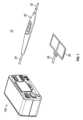
図1を参照すると、単極電気外科用器具20などの、本開示による電極を有する電気外科用器具で使用するための電気外科システム10。単極電気外科用器具20は、患者の組織を治療するための活性電極30(例えば、電気外科用切断ブレードなど)を含む。システム10は、使用時に、患者との全体的な接触面積を最大化することによって組織損傷の可能性を最小限に抑えるために患者上に配設される複数の戻り電極パッド26を含み得る。電気外科用交流RF電流は、供給ライン24を介して発電機100によって単極電気外科用器具20に供給される。交流RF電流は、戻りライン28を介して戻り電極パッド26を通って発電機100に戻される。 Referring to FIG. 1, an
図2を参照すると、電極30は、ステンレス鋼などの導電性タイプの材料から形成される。電極30は、器具20に結合するように構成された近位端34を有する長手方向ロッド32として成形され得る。電極30は絶縁部分36を有し、絶縁部分36は、近位端部分34及び遠位端部分35を露出させたまま、長手方向ロッド32の中央部分を覆って配設されたコーティング又は絶縁スリーブであってもよい。電極30はまた、その遠位端部分35に作動部分38を含む。作動部分38は、ブレード、又はヘら、フック、針などの任意の他の好適な構造のように成形され得る。 Referring to FIG. 2,
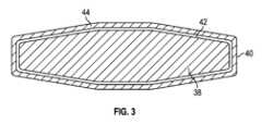
作動部分38は、その外面に配設された複合コーティング40を含む。図3を参照すると、第1の(例えば、底部、内側)のコーティング42及び第2の(例えば、上部、外側の)コーティング44を有する複合コーティング40を備えた作動部分38の断面図。作動部分38は、第1のコーティング42のより良好な接着性を提供するために粗いテクスチャを有する。粗面化されたテクスチャは、作動部分38のサンドブラスト又はエッチングなどの任意の他の好適な技術によって達成され得る。作動部分38の表面は、約0.6Ra~約0.8Raの粗さを有し得る。 Working
作動部分38が粗面化された後、第1のコーティング42が、所望の厚さを達成するように塗布される。第1のコーティング42は、約7μm~約9μmの厚さを有することができる。第1のコーティング42は、PTFEなどのポリマーから形成され、これは、高圧空気供給を使用してPTFE溶液を霧化又はエアロゾル化し、作動部分38の表面上にPTFE溶液を噴霧することによって塗布され得る。その後、第1の被膜42は、乾燥され焼結される。 After the working
第1のコーティング42が固化すると、第2のコーティング44が第1のコーティング42に塗布される。第2のコーティング44は、第1のコーティング42の第1のポリマーとは異なる第2のポリマーから形成されてもよい。第2のコーティング44は、PFA粒子から形成された粉体コーティングであってもよく、所望の厚さが達成されるまで第1のコーティング42上に噴霧することによって形成されてもよい。第2のコーティング44は、約12μm~約15μmの厚さを有することができる。複合コーティング40は、約19μm~約24μmの組み合わせた厚さを有することができる。 Once the
図4を参照すると、コーティング40の拡大写真が示されており、コーティング40の表面粗さ及びその均一性を示している。第2のコーティング44の粗さは、約0.2Ra~約0.4Raであり得る。したがって、コーティング40は、作動部分38の基材よりも滑らかである。二重層コーティング40の比較的薄い厚さは、電極30の所望の電気的性能を可能にする一方で、組織付着を低減させる。加えて、コーティング40を有する電極30は、約260℃~約290℃の温度で連続的に使用され得る。 Referring to FIG. 4, an enlarged photograph of the
以下の実施例は、本開示の実施形態を例示する。これらの実施例は、例示のみを意図しており、本開示の範囲を限定することを意図していない。また、割合及び百分率は、他に示されない限り重量による。本明細書で使用される場合、「室温」又は「周囲温度」は、約20℃~約25℃の温度を指す。 The following examples illustrate embodiments of the present disclosure. These examples are intended to be illustrative only and are not intended to limit the scope of this disclosure. Also, parts and percentages are by weight unless otherwise indicated. As used herein, "room temperature" or "ambient temperature" refers to a temperature of about 20°C to about 25°C.
実施例
実施例1
この実施例は、本開示による二重層PTFE/PFAコーティングの有効性を、コーティングされていない、シリコーンコーティングされた、及び単層PTFEコーティングされた電極と比較して説明する。Example Example 1
This example illustrates the effectiveness of a dual layer PTFE/PFA coating according to the present disclosure compared to uncoated, silicone coated, and single layer PTFE coated electrodes.
本開示のコーティングの有効性を決定するために、コーティングされていない電極、シリコーンコーティングされた電極、PTFEコーティングされた電極、及び本開示による複合コーティングされた電極を含む4つの電極を使用した。電極の各々は、Minneapolis,MNのMedtronicから入手可能なVALLEYLAB(商標)FT10(登録商標)発電機を用いて、10ワット設定の手動切断モードで使用された。電極を使用してブタ肝臓組織に切開を行い、図5に示されている。複合コーティングを有する電極のブレード切断跡は、他の電極によって行われた切断と比較してより狭かった。また、切断性能の熱拡散も他の電極のものよりも小さかった。 To determine the effectiveness of the coatings of the present disclosure, four electrodes were used, including an uncoated electrode, a silicone coated electrode, a PTFE coated electrode, and a composite coated electrode according to the present disclosure. Each of the electrodes was used in manual disconnect mode at a 10 watt setting using a VALLEYLAB™ FT10™ generator available from Medtronic of Minneapolis, MN. An incision was made in the pig liver tissue using electrodes and is shown in Figure 5. The blade cut trace of the electrode with composite coating was narrower compared to the cuts made by other electrodes. The thermal diffusion of cutting performance was also smaller than that of other electrodes.
疲労試験もまた、4つの電極について実行されて、複数の切断後のそれらの有効性を判定した。コーティングされていない電極を、別のPTFEコーティングされた電極(PTFE2)と置き換えた。疲労試験については、20回の切断が各電極を用いて行われ、コーティングが破損するまで電極を試験して、コーティングの耐久性を評価した。電極をガントリシステムに取り付けて、切断の長さ、深さ、及び速度を制御した。具体的には、電極を使用して、約10mm/sの速度で、ほぼ2mmの深さを有する40mmの切断を行った。切断中、発電機は、15ワット設定の手動切断モードであった。図6~図9は、5回の切断のグループで電極の各々によってブタ肝臓組織に行われた切断を示す。したがって、図6~図9の各々は、5回の切断各々の4つのラウンドを示す。 Fatigue testing was also performed on the four electrodes to determine their effectiveness after multiple cuts. The uncoated electrode was replaced with another PTFE coated electrode (PTFE2). For fatigue testing, 20 cuts were made with each electrode and the electrodes were tested until the coating failed to evaluate the durability of the coating. Electrodes were attached to a gantry system to control the length, depth, and speed of the cut. Specifically, the electrode was used to make a 40 mm cut with a depth of approximately 2 mm at a speed of approximately 10 mm/s. During the cut, the generator was in manual cut mode with a 15 watt setting. Figures 6-9 show cuts made in pig liver tissue by each of the electrodes in groups of five cuts. Therefore, each of FIGS. 6-9 shows four rounds of five cuts each.
最初の1~15回の切断では、複合コーティングされた電極を用いて行われた切断の幅は、他のコーティングを有する電極を用いて行われたものよりも狭かった。更に、第1のPTFEコーティングされた電極(PTFE1)は、10回の切断後に故障した。20回の切断後、シリコーンコーティングされた電極は完全に切断するのに失敗し、途切れのない切断跡を形成することができなかったのに対して、複合コーティングされた電極は滑らかにかつ平坦に切断した。加えて、電極の各々の付着性及び洗浄性を評価し、結果を図10の表に含めた。複合コーティングされた電極はまた、他の3つのコーティングされた電極よりも性能が優れていた。 For the first 1 to 15 cuts, the width of the cuts made with the composite coated electrode was narrower than those made with electrodes with other coatings. Furthermore, the first PTFE coated electrode (PTFE1) failed after 10 cuts. After 20 cuts, the silicone coated electrode failed to cut completely and could not form an uninterrupted cut track, whereas the composite coated electrode could cut smoothly and flatly. Amputated. In addition, the adhesion and cleanability of each of the electrodes was evaluated and the results are included in the table of FIG. The composite coated electrode also outperformed the other three coated electrodes.
本開示のいくつかの実施形態を図面で示し、及び/又は本明細書に説明してきたが、それによって本開示が限定されることを意図するものではなく、本開示が当該技術分野で可能な限り広い範囲を対象とすること、及び本明細書も同様に解釈されることが意図されている。したがって、上記の説明は、限定として解釈されるべきではなく、特定の実施形態の単なる例示として解釈されるべきである。当業者であれば、本明細書に添付される特許請求の範囲内での他の修正を想定するであろう。 Although some embodiments of the present disclosure have been shown in the drawings and/or described herein, the present disclosure is not intended to be limited thereby, and the present disclosure is not intended to be limited thereby; It is intended to be as broad in scope as possible and that the specification be construed in the same manner. Therefore, the above description should not be construed as limiting, but merely as exemplifications of particular embodiments. Those skilled in the art will envision other modifications within the scope of the claims appended hereto.
Claims (20)
Translated fromJapanese遠位端部分に作動部分を有する導電性ロッドと、
前記作動部分上に配設された複合コーティングであって、前記複合コーティングが、前記作動部分の外面上に配設された第1のコーティング、及び前記第1のコーティングを覆って配設された第2のコーティングを含む、複合コーティングと、備える、電気外科用電極。An electrosurgical electrode,
an electrically conductive rod having an actuating portion at a distal end portion;
a composite coating disposed on the working portion, the composite coating comprising: a first coating disposed on an outer surface of the working portion; and a first coating disposed over the first coating. An electrosurgical electrode comprising: a composite coating comprising two coatings.
作動部分を有する遠位端部分、及び電気外科用器具に結合するように構成された近位端部分を含む、導電性ロッドと、
前記作動部分上に配設された複合コーティングであって、前記複合コーティングが、前記作動部分の外面上に配設された第1のポリマーから形成された第1のコーティング、及び前記第1のコーティングを覆って配設された第2のコーティングを含み、前記第2のコーティングが、前記第1のポリマーとは異なる第2のポリマーから形成されている、複合コーティングと、を備える、電気外科用電極。An electrosurgical electrode,
an electrically conductive rod including a distal end portion having an actuating portion and a proximal end portion configured to couple to an electrosurgical instrument;
a composite coating disposed on the working portion, the composite coating comprising: a first coating formed from a first polymer disposed on an outer surface of the working portion; and a first coating disposed on the working portion; a second coating disposed over the electrode, the second coating being formed from a second polymer different from the first polymer. .
電気外科用電極の作動部分をテクスチャリングし、
前記作動部分の外面に第1のポリマーから形成された第1のコーティングを塗布し、かつ
前記第1のコーティング上に、前記第1のポリマーとは異なる第2のポリマーから形成された第2のコーティングを塗布することを含む、方法。A method for making an electrosurgical electrode, the method comprising:
Texturing the actuating part of the electrosurgical electrode;
applying a first coating formed from a first polymer to an outer surface of the working portion; and applying a second coating formed from a second polymer different from the first polymer onto the first coating. A method comprising applying a coating.
Applications Claiming Priority (1)
| Application Number | Priority Date | Filing Date | Title |
|---|---|---|---|
| PCT/CN2020/102269WO2022011627A1 (en) | 2020-07-16 | 2020-07-16 | Composite coating for electrosurgical electrode |
Publications (2)
| Publication Number | Publication Date |
|---|---|
| JP2023542454Atrue JP2023542454A (en) | 2023-10-10 |
| JP7523661B2 JP7523661B2 (en) | 2024-07-26 |
Family
ID=79555925
Family Applications (1)
| Application Number | Title | Priority Date | Filing Date |
|---|---|---|---|
| JP2023502649AActiveJP7523661B2 (en) | 2020-07-16 | 2020-07-16 | Composite coatings for electrosurgical electrodes |
Country Status (5)
| Country | Link |
|---|---|
| US (1) | US20230225785A1 (en) |
| EP (1) | EP4181807A4 (en) |
| JP (1) | JP7523661B2 (en) |
| CN (1) | CN116234512A (en) |
| WO (1) | WO2022011627A1 (en) |
Citations (5)
| Publication number | Priority date | Publication date | Assignee | Title |
|---|---|---|---|---|
| US4785807A (en)* | 1987-02-24 | 1988-11-22 | American Medical Products, Inc. | Electrosurgical knife |
| US5693050A (en)* | 1995-11-07 | 1997-12-02 | Aaron Medical Industries, Inc. | Electrosurgical instrument |
| US20020111622A1 (en)* | 2000-02-01 | 2002-08-15 | Khandkar Ashok C. | Electrosurgical knife |
| JP2010284439A (en)* | 2009-06-15 | 2010-12-24 | Olympus Corp | Electrode for medical device and medical treatment tool |
| WO2020027341A1 (en)* | 2018-08-03 | 2020-02-06 | 日本パーカライジング株式会社 | Surgical electrode having surface treatment coating |
Family Cites Families (12)
| Publication number | Priority date | Publication date | Assignee | Title |
|---|---|---|---|---|
| US5702387A (en)* | 1995-09-27 | 1997-12-30 | Valleylab Inc | Coated electrosurgical electrode |
| US6409725B1 (en)* | 2000-02-01 | 2002-06-25 | Triad Surgical Technologies, Inc. | Electrosurgical knife |
| CN2548571Y (en)* | 2002-06-12 | 2003-05-07 | 常州华森医疗器械有限公司 | Surgical knife against carbon deposition |
| US20040115477A1 (en)* | 2002-12-12 | 2004-06-17 | Bruce Nesbitt | Coating reinforcing underlayment and method of manufacturing same |
| JP4391440B2 (en)* | 2005-04-05 | 2009-12-24 | ジョンソン・エンド・ジョンソン株式会社 | Bipolar tweezers |
| US20080188845A1 (en)* | 2007-02-01 | 2008-08-07 | Mcgreevy Francis T | Tissue fusion instrument and method to reduce the adhesion of tissue to its working surfaces |
| JP4977599B2 (en)* | 2007-12-27 | 2012-07-18 | オキツモ株式会社 | Method for forming a fluororesin lubricating film on the surface of a substrate |
| WO2016051918A1 (en)* | 2014-09-30 | 2016-04-07 | トーカロ株式会社 | Energy device for surgical operations |
| US10441349B2 (en)* | 2015-10-29 | 2019-10-15 | Covidien Lp | Non-stick coated electrosurgical instruments and method for manufacturing the same |
| CN207679526U (en)* | 2017-01-24 | 2018-08-03 | 上海逸思医疗科技有限公司 | A kind of electrode of electrosurgical unit |
| CN109077620B (en)* | 2017-06-14 | 2024-07-19 | 佛山市顺德区美的电热电器制造有限公司 | Non-stick coating, preparation method thereof, pan or baking tray panel and cooking equipment |
| CN209004193U (en)* | 2018-02-13 | 2019-06-21 | 柯惠有限合伙公司 | An electrosurgical instrument and end effector assembly |
- 2020
- 2020-07-16CNCN202080104863.7Apatent/CN116234512A/enactivePending
- 2020-07-16USUS18/010,232patent/US20230225785A1/enactivePending
- 2020-07-16WOPCT/CN2020/102269patent/WO2022011627A1/ennot_activeCeased
- 2020-07-16EPEP20945211.9Apatent/EP4181807A4/enactivePending
- 2020-07-16JPJP2023502649Apatent/JP7523661B2/enactiveActive
Patent Citations (6)
| Publication number | Priority date | Publication date | Assignee | Title |
|---|---|---|---|---|
| US4785807A (en)* | 1987-02-24 | 1988-11-22 | American Medical Products, Inc. | Electrosurgical knife |
| US4785807B1 (en)* | 1987-02-24 | 1996-07-16 | American Medical Products Inc | Electrosurgical knife |
| US5693050A (en)* | 1995-11-07 | 1997-12-02 | Aaron Medical Industries, Inc. | Electrosurgical instrument |
| US20020111622A1 (en)* | 2000-02-01 | 2002-08-15 | Khandkar Ashok C. | Electrosurgical knife |
| JP2010284439A (en)* | 2009-06-15 | 2010-12-24 | Olympus Corp | Electrode for medical device and medical treatment tool |
| WO2020027341A1 (en)* | 2018-08-03 | 2020-02-06 | 日本パーカライジング株式会社 | Surgical electrode having surface treatment coating |
Also Published As
| Publication number | Publication date |
|---|---|
| US20230225785A1 (en) | 2023-07-20 |
| WO2022011627A1 (en) | 2022-01-20 |
| EP4181807A1 (en) | 2023-05-24 |
| JP7523661B2 (en) | 2024-07-26 |
| EP4181807A4 (en) | 2024-04-10 |
| CN116234512A (en) | 2023-06-06 |
Similar Documents
| Publication | Publication Date | Title |
|---|---|---|
| CA2290020C (en) | Electro-surgical blade with a conductive, non-stick coating | |
| US5693050A (en) | Electrosurgical instrument | |
| US20220202473A1 (en) | Non-stick coated electrosurgical instruments and method for manufacturing the same | |
| US11969204B2 (en) | Non-stick coated electrosurgical instruments and method for manufacturing the same | |
| JP4524177B2 (en) | Conductive / insulating overshoe for tissue fusion | |
| US20080221567A1 (en) | Electrosurgical tissue removal with a selectively insulated electrode | |
| JP2004267644A (en) | Electrodes for biological tissue processing | |
| JPH09103464A (en) | Bipolar type electric moxa cautery apparatus | |
| WO2000016706A1 (en) | Electrosurgical instruments | |
| JP6180671B2 (en) | Medical equipment, coating materials | |
| US8956354B2 (en) | Anti-sticking electrosurgical instrument | |
| JP6438935B2 (en) | Coating system comprising ZrO2 for electrosurgical devices, medical devices having a coating system, and methods for coating medical devices | |
| JP7523661B2 (en) | Composite coatings for electrosurgical electrodes | |
| JP7717045B2 (en) | Electrosurgical Electrodes | |
| WO2023039703A1 (en) | Monopolar l-hook electrode | |
| US20230301704A1 (en) | Monopolar l-hook electrode with varied cross-sections | |
| JP2011024871A (en) | Treatment unit for medical instrument, medical instrument, and method for manufacturing the treatment unit for medical instrument | |
| KR20010092480A (en) | A knife for electric operation | |
| TW201434432A (en) | Electrosurgical unit with diamond like carbon film and manufacturing method thereof | |
| TWM437153U (en) | Improved electrocauterization device improvement for preventing tissue adhesion |
Legal Events
| Date | Code | Title | Description |
|---|---|---|---|
| A621 | Written request for application examination | Free format text:JAPANESE INTERMEDIATE CODE: A621 Effective date:20230714 | |
| A977 | Report on retrieval | Free format text:JAPANESE INTERMEDIATE CODE: A971007 Effective date:20240229 | |
| A131 | Notification of reasons for refusal | Free format text:JAPANESE INTERMEDIATE CODE: A131 Effective date:20240307 | |
| A521 | Request for written amendment filed | Free format text:JAPANESE INTERMEDIATE CODE: A523 Effective date:20240606 | |
| TRDD | Decision of grant or rejection written | ||
| A01 | Written decision to grant a patent or to grant a registration (utility model) | Free format text:JAPANESE INTERMEDIATE CODE: A01 Effective date:20240617 | |
| A61 | First payment of annual fees (during grant procedure) | Free format text:JAPANESE INTERMEDIATE CODE: A61 Effective date:20240716 | |
| R150 | Certificate of patent or registration of utility model | Ref document number:7523661 Country of ref document:JP Free format text:JAPANESE INTERMEDIATE CODE: R150 |