JP2023541895A - Aerosol generation system - Google Patents
Aerosol generation systemDownload PDFInfo
- Publication number
- JP2023541895A JP2023541895AJP2023516141AJP2023516141AJP2023541895AJP 2023541895 AJP2023541895 AJP 2023541895AJP 2023516141 AJP2023516141 AJP 2023516141AJP 2023516141 AJP2023516141 AJP 2023516141AJP 2023541895 AJP2023541895 AJP 2023541895A
- Authority
- JP
- Japan
- Prior art keywords
- heating element
- delivery device
- wall
- aerosol delivery
- heating
- Prior art date
- Legal status (The legal status is an assumption and is not a legal conclusion. Google has not performed a legal analysis and makes no representation as to the accuracy of the status listed.)
- Pending
Links
Images


Classifications
- A—HUMAN NECESSITIES
- A24—TOBACCO; CIGARS; CIGARETTES; SIMULATED SMOKING DEVICES; SMOKERS' REQUISITES
- A24F—SMOKERS' REQUISITES; MATCH BOXES; SIMULATED SMOKING DEVICES
- A24F40/00—Electrically operated smoking devices; Component parts thereof; Manufacture thereof; Maintenance or testing thereof; Charging means specially adapted therefor
- A24F40/40—Constructional details, e.g. connection of cartridges and battery parts
- A24F40/46—Shape or structure of electric heating means
- A24F40/465—Shape or structure of electric heating means specially adapted for induction heating
- A—HUMAN NECESSITIES
- A24—TOBACCO; CIGARS; CIGARETTES; SIMULATED SMOKING DEVICES; SMOKERS' REQUISITES
- A24F—SMOKERS' REQUISITES; MATCH BOXES; SIMULATED SMOKING DEVICES
- A24F40/00—Electrically operated smoking devices; Component parts thereof; Manufacture thereof; Maintenance or testing thereof; Charging means specially adapted therefor
- A24F40/40—Constructional details, e.g. connection of cartridges and battery parts
- A24F40/48—Fluid transfer means, e.g. pumps
- A24F40/485—Valves; Apertures
- A—HUMAN NECESSITIES
- A24—TOBACCO; CIGARS; CIGARETTES; SIMULATED SMOKING DEVICES; SMOKERS' REQUISITES
- A24F—SMOKERS' REQUISITES; MATCH BOXES; SIMULATED SMOKING DEVICES
- A24F40/00—Electrically operated smoking devices; Component parts thereof; Manufacture thereof; Maintenance or testing thereof; Charging means specially adapted therefor
- A24F40/70—Manufacture
- F—MECHANICAL ENGINEERING; LIGHTING; HEATING; WEAPONS; BLASTING
- F16—ENGINEERING ELEMENTS AND UNITS; GENERAL MEASURES FOR PRODUCING AND MAINTAINING EFFECTIVE FUNCTIONING OF MACHINES OR INSTALLATIONS; THERMAL INSULATION IN GENERAL
- F16L—PIPES; JOINTS OR FITTINGS FOR PIPES; SUPPORTS FOR PIPES, CABLES OR PROTECTIVE TUBING; MEANS FOR THERMAL INSULATION IN GENERAL
- F16L59/00—Thermal insulation in general
- F16L59/06—Arrangements using an air layer or vacuum
- F16L59/065—Arrangements using an air layer or vacuum using vacuum
- H—ELECTRICITY
- H05—ELECTRIC TECHNIQUES NOT OTHERWISE PROVIDED FOR
- H05B—ELECTRIC HEATING; ELECTRIC LIGHT SOURCES NOT OTHERWISE PROVIDED FOR; CIRCUIT ARRANGEMENTS FOR ELECTRIC LIGHT SOURCES, IN GENERAL
- H05B3/00—Ohmic-resistance heating
- H05B3/20—Heating elements having extended surface area substantially in a two-dimensional plane, e.g. plate-heater
- H05B3/22—Heating elements having extended surface area substantially in a two-dimensional plane, e.g. plate-heater non-flexible
- H05B3/26—Heating elements having extended surface area substantially in a two-dimensional plane, e.g. plate-heater non-flexible heating conductor mounted on insulating base
- A—HUMAN NECESSITIES
- A24—TOBACCO; CIGARS; CIGARETTES; SIMULATED SMOKING DEVICES; SMOKERS' REQUISITES
- A24F—SMOKERS' REQUISITES; MATCH BOXES; SIMULATED SMOKING DEVICES
- A24F40/00—Electrically operated smoking devices; Component parts thereof; Manufacture thereof; Maintenance or testing thereof; Charging means specially adapted therefor
- A24F40/20—Devices using solid inhalable precursors
Landscapes
- Engineering & Computer Science (AREA)
- General Engineering & Computer Science (AREA)
- Mechanical Engineering (AREA)
- Resistance Heating (AREA)
Abstract
Translated fromJapanese
Description
Translated fromJapanese本発明は、エアロゾル供給デバイス、このエアロゾル供給デバイスを用いてエアロゾルを生成する方法、及びこのエアロゾル供給デバイスを備えるエアロゾル生成システムに関する。 The present invention relates to an aerosol supply device, a method of generating an aerosol using this aerosol supply device, and an aerosol generation system including this aerosol supply device.
シガレット、及びシガーなどの喫煙品は、使用中にタバコを燃焼させてタバコの煙を生じさせる。タバコを燃焼させるこれらの物品の代替品を、燃焼させずに化合物を放出する製品を作り出すことによって提供しようとする試みがなされてきた。このような製品の例としては、材料を燃焼させるのではなく加熱することによって化合物を放出する加熱デバイスがある。この材料は、例えばタバコ又は他の非タバコ製品でもよく、これらはニコチンを含んでも含まなくてもよい。 Cigarettes and smoking articles, such as cigars, produce tobacco smoke by burning tobacco during use. Attempts have been made to provide an alternative to these articles that burn tobacco by creating products that release compounds without burning. Examples of such products include heating devices that release compounds by heating the material rather than burning it. This material may be, for example, tobacco or other non-tobacco products, which may or may not contain nicotine.
本開示の第1の態様によれば、エアロゾル生成材料を加熱してエアロゾル生成材料の少なくとも1つの成分を揮発させるための非燃焼式エアロゾル供給デバイスが提供され、このデバイスは、エアロゾル生成材料を含む消耗品の少なくとも一部分を受け入れるための加熱ゾーンを少なくとも部分的に画定する第1の加熱要素と、第1の加熱要素の軸線方向端部から加熱ゾーンを越えて延びる第2の加熱要素と、断熱材であって、内壁、外壁、並びに内壁及び外壁で巻かれた断熱領域であり、この断熱領域が、この断熱領域の外部よりも低い圧力に排気されている、断熱領域を備える、断熱材とを具備し、断熱材は、第1の加熱要素の少なくとも一部及び第2加熱要素の少なくとも一部のまわりに延びるように配置されている。 According to a first aspect of the present disclosure, a non-combustion aerosol delivery device is provided for heating an aerosol-generating material to volatilize at least one component of the aerosol-generating material, the device comprising an aerosol-generating material. a first heating element at least partially defining a heating zone for receiving at least a portion of a consumable; a second heating element extending beyond the heating zone from an axial end of the first heating element; an insulating material comprising an inner wall, an outer wall, and an insulating region wrapped around the inner and outer walls, the insulating region being evacuated to a lower pressure than the outside of the insulating region; and the insulation is disposed to extend around at least a portion of the first heating element and at least a portion of the second heating element.
本開示の第2の態様によれば、エアロゾル生成材料を加熱してエアロゾル生成材料の少なくとも1つの成分を揮発させるための非燃焼式エアロゾル供給デバイスが提供され、このデバイスは、エアロゾル生成材料を含む消耗品の少なくとも一部分を受け入れるための加熱ゾーンを少なくとも部分的に画定する第1の加熱要素と、第1の加熱要素の軸線方向端部から加熱ゾーンを越えて延びる第2の加熱要素と、断熱材であって、内壁、外壁、並びに内壁及び外壁で巻かれた断熱領域であり、この断熱領域が、この断熱領域の外部よりも低い圧力に排気されている、断熱領域を備える、断熱材とを具備し、内壁は、第1の加熱要素及び第2の加熱要素のそれぞれの少なくとも一部を備える。 According to a second aspect of the present disclosure, a non-combustion aerosol delivery device is provided for heating an aerosol-generating material to volatilize at least one component of the aerosol-generating material, the device comprising an aerosol-generating material. a first heating element at least partially defining a heating zone for receiving at least a portion of a consumable; a second heating element extending beyond the heating zone from an axial end of the first heating element; an insulating material comprising an inner wall, an outer wall, and an insulating region wrapped around the inner and outer walls, the insulating region being evacuated to a lower pressure than the outside of the insulating region; , the inner wall including at least a portion of each of the first heating element and the second heating element.
本開示の第3の態様によれば、本開示の第1又は第2の態様による装置と、使用時に第1及び/又は第2の加熱要素の加熱ゾーン内に少なくとも部分的に配置されるエアロゾル生成材料とを備える、非燃焼式エアロゾル供給システムが提供される。
本発明のさらなる特徴及び利点は、単なる例として示された本発明の好ましい実施形態についての、添付の図面を参照することによってなされる以下の説明から明らかになろう。According to a third aspect of the disclosure, there is provided an apparatus according to the first or second aspect of the disclosure and an aerosol which, in use, is at least partially located within the heating zone of the first and/or second heating element. A non-combustion aerosol delivery system is provided comprising: a generating material;
Further features and advantages of the invention will become apparent from the following description of preferred embodiments of the invention, given by way of example only, with reference to the accompanying drawings, in which: FIG.
次に、本発明の実施形態について、単なる例として添付の図面を参照して説明する。 Embodiments of the invention will now be described, by way of example only, with reference to the accompanying drawings, in which: FIG.
本明細書では、「エアロゾル生成材料」という用語は、加熱したときに通常はエアロゾルの形で揮発成分を供給する材料を含む。エアロゾル生成材料は、何らかのタバコ含有材料を含み、例えば、タバコ、タバコ派生物、膨張タバコ、再生タバコ、又はタバコ代替品のうちの1つ又は複数を含み得る。エアロゾル生成材料は、他の非タバコ製品を含むこともあり、これは製品によって、ニコチンを含むことも含まないこともある。エアロゾル生成材料は、例えば、固体、液体、ゲル、又はワックスなどの形とすることができる。エアロゾル生成材料は、例えば、複数の材料の組合せ又は混合物とすることもできる。エアロゾル生成材料は、「喫煙材」と呼ばれることもある。 As used herein, the term "aerosol-generating material" includes materials that, when heated, typically provide volatile components in the form of an aerosol. The aerosol-generating material may include any tobacco-containing material, such as one or more of tobacco, tobacco derivatives, expanded tobacco, regenerated tobacco, or tobacco substitutes. Aerosol-generating materials may also include other non-tobacco products, which may or may not contain nicotine, depending on the product. Aerosol-generating materials can be in the form of, for example, solids, liquids, gels, or waxes. The aerosol-generating material can also be a combination or mixture of materials, for example. Aerosol-generating materials are sometimes referred to as "smokable materials."
エアロゾル生成器を使用してエアロゾル生成材料からエアロゾルを生成する装置が知られている。エアロゾルを生成する特に一般的な1つの方法は、エアロゾル生成材料を加熱することによるものである。このような装置では、エアロゾル生成器はヒータであり、このヒータは、エアロゾル生成材料を加熱してエアロゾル生成材料の少なくとも1つの成分を揮発させ、典型的には、吸入することができるエアロゾルを、エアロゾル生成材料を焼いたり燃焼させたりすることなく形成する。このような装置は、場合によって「エアロゾル供給デバイス」、「非燃焼加熱式デバイス」、「タバコ加熱製品デバイス」又は「タバコ加熱デバイス」などと記述される。同様に、いわゆるeシガレットデバイスもあり、これは通常、ニコチンを含むことも含まないこともある液体の形のエアロゾル生成材料を気化させる。エアロゾル生成材料は、装置に挿入できるロッド、カートリッジ、又はカセットなどの形にすることも、これらの一部として形成することもできる。エアロゾル生成材料を揮発させるためのエアロゾル生成器は、装置の「恒久的」部分として設けられてもよく、又は交換可能品若しくは消耗品の構成要素中のエアロゾル生成物質と組み合わせることもできる。本開示では、ヒータであるエアロゾル生成器に注目するが、エアロゾル生成材料からエアロゾルを生成する代替方法もまた利用可能であることを理解されたい。 Devices are known that use aerosol generators to generate aerosols from aerosol-generating materials. One particularly common method of generating aerosols is by heating the aerosol-generating material. In such devices, the aerosol generator is a heater that heats the aerosol-generating material to volatilize at least one component of the aerosol-generating material and typically produces an aerosol that can be inhaled. Forming the aerosol-generating material without baking or combusting it. Such devices are sometimes described as "aerosol delivery devices," "non-combustion heating devices," "tobacco heated product devices," or "tobacco heating devices." There are also so-called e-cigarette devices, which typically vaporize an aerosol-generating material in liquid form, which may or may not contain nicotine. The aerosol-generating material can be in the form of, or formed as part of, a rod, cartridge, or cassette that can be inserted into the device. The aerosol generator for volatilizing the aerosol-generating material may be provided as a "permanent" part of the device, or may be combined with the aerosol-generating material in a replaceable or consumable component. Although this disclosure focuses on aerosol generators that are heaters, it should be understood that alternative methods of generating aerosols from aerosol-generating materials are also available.
エアロゾル供給デバイスは、エアロゾル生成材料を含む物品を受け入れ加熱することができる。この文脈における「物品」とは、加熱されてエアロゾル生成材料を揮発させるエアロゾル生成材料を使用時に、また任意選択で他の構成要素を使用時に含んでいるか含有する構成要素のことである。使用者は、物品が加熱される前に、物品をこのエアロゾル供給デバイスに挿入し、加熱してエアロゾルを生成することができ、続いて、そのエアロゾルを使用者が吸入する。物品は、例えば、物品を受け入れるように寸法設定されたこのデバイスの加熱チャンバの中に入るように構成されている、予め定められた、又は特定のサイズとすることができる。代替として、エアロゾル生成材料は、デバイスの加熱チャンバ内に自由に、又は制約なしに単純に入れられてもよく、例えば、非結束葉タバコは、このようにして使用することができる。 The aerosol delivery device is capable of receiving and heating an article containing an aerosol-generating material. An "article" in this context refers to a component that, in use, contains or contains an aerosol-generating material that is heated to volatilize the aerosol-generating material, and optionally other components. Before the article is heated, the user can insert the article into the aerosol delivery device and heat it to generate an aerosol, which is then inhaled by the user. The article may be of a predetermined or specified size, for example, configured to fit into a heating chamber of the device that is dimensioned to receive the article. Alternatively, the aerosol-generating material may simply be placed freely or without restriction into the heating chamber of the device; for example, unbound tobacco can be used in this way.
誘導加熱とは、導電性の物体が、変動磁場がその物体を貫通することによって加熱されるプロセスである。このプロセスは、ファラデーの誘導の法則及びオームの法則によって説明される。誘導ヒータは、電磁石と、この電磁石に交流などの変動電流を通すためのデバイスとを備えることができる。電磁石と加熱されるべき物体とが、電磁石によって生成された変動磁場が物体を貫通するように適切に相対的に配置されると、1つ又は複数の渦電流が物体の内部に生成される。物体には、電流の流れに対する抵抗がある。したがって、このような渦電流が物体中に生成されると、それが物体の電気抵抗に抗して流れることで物体が加熱される。このプロセスは、ジュール加熱、オーミック加熱、又は抵抗加熱と呼ばれる。誘導加熱されることが可能である物体は、サセプタとして知られている。 Induction heating is a process in which an electrically conductive object is heated by passing a varying magnetic field through the object. This process is explained by Faraday's law of induction and Ohm's law. An induction heater can include an electromagnet and a device for passing a varying current, such as an alternating current, through the electromagnet. When the electromagnet and the object to be heated are appropriately positioned relative to each other such that the varying magnetic field generated by the electromagnet penetrates the object, one or more eddy currents are generated inside the object. Objects have resistance to the flow of current. Therefore, when such eddy currents are generated in an object, they flow against the electrical resistance of the object, thereby heating the object. This process is called Joule heating, ohmic heating, or resistance heating. Objects that can be inductively heated are known as susceptors.
磁気ヒステリシス加熱とは、磁性材料で作られた物体が、その物体に変動磁場を侵入させることによって加熱されるプロセスのことである。磁性材料は、多くの原子スケールの磁石、すなわち磁気双極子を含むと考えることができる。このような材料に磁場を侵入させると、磁気双極子は磁場に合わせて整列する。したがって、例えば電磁石によって生成されるような交番磁場等の変動磁場が磁性材料に侵入すると、磁気双極子の向きが、変動印加磁場によって変化する。このような磁気双極子の再配向により、熱が磁性材料中に発生する。 Magnetic hysteresis heating is a process in which an object made of magnetic material is heated by penetrating the object with a varying magnetic field. Magnetic materials can be thought of as containing many atomic scale magnets, or magnetic dipoles. When a magnetic field is applied to such a material, the magnetic dipoles align with the field. Thus, when a varying magnetic field, such as an alternating magnetic field such as that produced by an electromagnet, penetrates the magnetic material, the orientation of the magnetic dipole changes due to the varying applied magnetic field. This reorientation of the magnetic dipoles generates heat in the magnetic material.
物体が導電性でも磁性でもある場合、変動磁場を物体に侵入させると、ジュール過熱と磁気ヒステリシス加熱の両方が物体中に生じ得る。さらに、磁性材料を使用すると磁場を強化することができ、こうすることで、ジュール加熱及び磁気ヒステリシス加熱を増強することができる。 If the object is both conductive and magnetic, penetrating the object with a varying magnetic field can cause both Joule superheating and magnetic hysteresis heating in the object. Additionally, magnetic materials can be used to strengthen the magnetic field, thereby increasing Joule heating and magnetic hysteresis heating.
上記のプロセスのそれぞれでは、熱が、外部熱源からの熱伝導によってではなく、物体自体の内部で発生するので、物体中の急速な温度上昇と、より均一な熱分布とが、特に適切な物体材料及び幾何形状と、適切な変動磁場の大きさ及び物体に対する配向とを選択することによって達成され得る。さらに、誘導加熱及び磁気ヒステリシス加熱は、変動磁場の供給源と物体との間が物理的に結合される必要がないので、設計の自由及び加熱プロファイルに対する制御性が大きくなることがあり、またコストが低くなることがある。 In each of the above processes, the heat is generated within the object itself, rather than by heat conduction from an external heat source, so a rapid temperature rise and a more uniform heat distribution within the object make it particularly suitable for This can be achieved by choosing the material and geometry and the appropriate varying magnetic field magnitude and orientation relative to the object. In addition, induction heating and magnetic hysteresis heating do not require a physical coupling between the source of the fluctuating magnetic field and the object, which can provide greater design freedom and control over the heating profile, and is less costly. may be low.
使用中にエアロゾルの形成を促進するために、エアロゾル供給デバイス(例えばタバコ加熱製品)用のエアロゾル生成材料は通常、燃焼式喫煙品中のエアロゾル生成材料よりも多くの水及び/又はエアロゾル生成剤を含有する。このように水及び/又はエアロゾル生成剤の含有量が高いと、使用中にこのエアロゾル供給デバイス内に凝縮水が集まるリスクが、特に加熱ユニット(複数可)から離れた場所において増大するおそれがある。凝縮水の生成は、誘導加熱システムによって実現されるような、比較的急速な加熱によって悪化し得ることが分かっている。 To promote aerosol formation during use, aerosol-generating materials for aerosol delivery devices (e.g., tobacco heating products) typically contain more water and/or aerosol-generating agent than the aerosol-generating materials in combustible smoking articles. contains. Such a high content of water and/or aerosol-forming agent may increase the risk of condensed water collecting within this aerosol delivery device during use, especially at locations remote from the heating unit(s). . It has been found that condensate formation can be exacerbated by relatively rapid heating, such as that achieved by induction heating systems.
この問題は、密閉された加熱室を備えたデバイスでは、より大きくなり得る。このようなデバイスでは、加熱チャンバは、導管(例えば入口又は出口の導管)によってこのデバイスの外部と流体接続されてもよい。導管は、それが接続されている加熱チャンバよりも著しく低い温度である傾向があるので、そのような導管内には凝縮水が集まるという特別なリスクがある。このような集まった凝縮水は、場合によってはこのデバイスから漏れ出して、あまり快適ではない使用者体験になることがある。追加的に、又はその代わりに、このような凝縮水が、時間の経過とともに乾燥して、導管の内面にガムを形成する可能性がある。このガムは、除去するのが困難なことがあり、したがって、時間の経過とともに塊になり得る。さらに、エアロゾル生成材料が消耗品中に含有されている場合には、ガムは消耗品に付着して、消耗品を変色させたり、使用後の消耗品の取り外しを妨げたりする可能性がある。 This problem may be greater for devices with closed heating chambers. In such devices, the heating chamber may be fluidly connected to the exterior of the device by a conduit (eg, an inlet or outlet conduit). There is a particular risk of condensed water collecting within such conduits, as they tend to be at a significantly lower temperature than the heating chamber to which they are connected. Such collected condensate can sometimes leak out of the device, resulting in a less pleasant user experience. Additionally, or alternatively, such condensed water can dry out over time and form a gum on the interior surface of the conduit. This gum can be difficult to remove and therefore can clump over time. Additionally, if the aerosol-generating material is included in the consumable, the gum can adhere to the consumable, discoloring the consumable, or preventing removal of the consumable after use.
したがって、エアロゾル供給デバイスは、所与の導管の内面が使用期間中に加熱されるように構成されることがあり、それにより、問題の導管内の凝縮水の蓄積が制限され、場合によっては実質的に防止されることがある。特に、導管の内面への凝縮水の堆積が低減され得る。 Accordingly, aerosol delivery devices may be configured such that the inner surface of a given conduit is heated during the period of use, thereby limiting the accumulation of condensed water within the conduit in question, and in some cases substantially may be prevented. In particular, the accumulation of condensate on the inner surface of the conduit may be reduced.
エアロゾル供給デバイスでは、発生する熱からユーザ及びデバイスの電子部品を保護するために、加熱チャンバのまわりに断熱が行われるのが一般的である。エアロゾル供給デバイスの導管もまた加熱される場合には、導管の構成要素の断熱もまた有益であることを理解されたい。本開示は、そのような断熱を、加熱チャンバもまた断熱するという状況で効果的及び効率的に行うことに対応する。 In aerosol delivery devices, insulation is typically provided around the heating chamber to protect the user and the device's electronics from the heat generated. It should be appreciated that if the conduit of the aerosol delivery device is also heated, insulation of the conduit components is also beneficial. The present disclosure addresses effectively and efficiently performing such insulation in situations where the heating chamber is also insulated.
図1は、本発明の一例によるエアロゾル供給デバイス100の概略断面図を示す。図2及び図3は、エアロゾル供給デバイス100に使用するための例示的な断熱材102の概略図を示す。断熱材102が図1に、分かりやすくするために簡略化された形で示されている。エアロゾル供給デバイス100の断熱材102は、それが加熱チャンバ又はゾーン144を備えているという点で、加熱されるべきエアロゾル生成材料(図示せず)を受け入れるように構成されている。消耗品(consumable article)又は「消耗品(consumable)」の中に供給することもできるエアロゾル生成材料は、エアロゾル供給デバイス100の加熱チャンバ144の開口部に挿入可能である。エアロゾル供給デバイス100は、使用時に、変動磁場を発生させるための磁場発生器106と、エアロゾル供給デバイス100の構成要素のそれぞれを収容するためのハウジング108とを含む。 FIG. 1 shows a schematic cross-sectional view of an aerosol delivery device 100 according to an example of the invention. 2 and 3 show schematic diagrams of an
この例では、磁場発生器106は、電源114と、交流電流などの変動電流をコイルに通すためのデバイス118とを備える。図1に示された例では、コイルは二パートコイル116a、116bである。図1に示されるようないくつかの例では、磁場発生器106はさらに、コントローラ120と、使用者がコントローラ120を操作するための使用者インタフェース122とに接続される。 In this example, the
電源114は、充電式バッテリー(リチウムイオンバッテリーなど)、非充電式バッテリー、コンデンサ、バッテリー・コンデンサハイブリッド、又は主電源との接続部とすることができる。
コイル116a、116bは、2つの部分を持つ単一コイルの形を含む、任意の適切な形をとることができ、単一部分コイルも代替形態として可能である。図1に示された例では、二パートコイル116a、116bは、銅などの導電性材料で作られた螺旋コイルである。いくつかの例では、コイル116a、116bは、フラットコイルであってもよい。すなわち、コイルは擬似二次元螺旋であってもよい。いくつかの例では、コイルはリッツ線を備えることがある。 The
エアロゾル供給デバイス100は、空気をデバイス100に引き込むことができるように装置の内部をエアロゾル供給デバイス100のハウジング108の外部と流体接続している入口導管130を含む。使用時、使用者は、エアロゾル生成材料を含む消耗品を吸うことによって、エアロゾル生成材料の揮発成分(複数可)を吸入することができる。揮発成分(複数可)がエアロゾル生成材料から取り出されるとき、空気が入口導管130を経由してエアロゾル供給デバイス100に引き込まれる。 Aerosol delivery device 100 includes an
断熱材102は、より詳細に図2~図7に示されている。図1~図7に示された例示的な断熱材102は、外壁、内壁、並びに内壁及び外壁で巻かれた断熱領域を備え、この断熱領域は、この断熱領域の外部よりも低い圧力に排気されている。実際には、断熱領域の外部の圧力は、ほとんどすべての場合で大気圧である。大気圧よりも圧力の低い断熱領域を設けることにより、加熱チャンバ/ゾーン144を外壁及びハウジング108から断熱して、加熱チャンバ/ゾーン144からエアロゾル供給デバイス100の残りの部分(加熱チャンバ/ゾーン144の外部)への熱伝達を制限する。この熱伝達制限は、電源114などのエアロゾル供給デバイス100の他の構成要素が温度の上昇の影響を受けやすいことがあるために、有利である。例えば、バッテリー及び他の電子回路は、高温にさらされた場合に損傷し、さらには危険でさえあり得ることはよく知られている。さらに、エアロゾル供給デバイス100のハウジング108への熱伝達は、使用時に、使用者に不快感、さらには傷害さえもたらすことがある。
図2は、本開示の第1の態様による断熱材202と中空チャンバ216との外部概略図を示し、断熱材202及び中空チャンバ216は、エアロゾル供給デバイス100の構成要素部品である。中空チャンバ216については、さらに詳細に以下で論じられる。 FIG. 2 shows an external schematic view of
図3は、図2に示された断熱材202の断面A-Aを示す。図2、3及び4は、原寸に比例して描かれていない。断熱材202は、内壁204及び外壁206を備える。内壁204及び外壁206は、断熱領域208を取り囲んでおり、この断熱領域は、断熱領域208の外部よりも低い圧力に排気されている。内壁204と外壁206は、任意の適切な手段で、例えば、溶接、ろう付けで一緒に接合すること、又は接着剤で互いに接着させることができる。断熱領域208の圧力は、10-1~10-7torrの範囲にあってもよく、10-3torr以下の圧力が特に有利であると考えられる。いくつかの例では、断熱領域208の圧力は真空と考えられる。断熱材202の内壁204と外壁206は、これらに対して断熱領域208と断熱領域208の外部の領域との間の圧力差により作用するいかなる力にも耐えるのに十分な強度があり、断熱材202が内側につぶれることを防止する。ガス吸収材料が、断熱領域208の比較的低い圧力を維持するために、又はその生成を助けるために断熱領域208で使用されてもよい。FIG. 3 shows a cross section AA of the
大気圧よりも低い圧力の断熱領域208を設けることは、代替の断熱オプションを用いて可能であり得るよりもサイズがはるかに小さい領域で非常に効果的な断熱が行われることを可能にするので、特に有利である。こうすると、加熱チャンバ/ゾーン144の断熱を損なうことなく、エアロゾル供給デバイス100の全体のサイズを最小限に保つことが可能になる。 Providing the insulation region 208 at a pressure below atmospheric pressure allows highly effective insulation to be performed in an area much smaller in size than would be possible with alternative insulation options. , is particularly advantageous. This allows the overall size of the aerosol delivery device 100 to be kept to a minimum without compromising the insulation of the heating chamber/
図3に示されたエアロゾル供給デバイス100の断面は、第1の加熱要素210及び第2の加熱要素212をさらに含む。第1の加熱要素210と第2の加熱要素212は、溶接、ろう付け、接着剤によって、又は締まり嵌めによってなど、任意の適切な手段で接合することができる。代替として、これらは単に互いに当接していてもよく、又は互いに隣り合って配置されていてもよい。図3に示された例では、第1の加熱要素210は、使用時にエアロゾル生成材料(図示せず)が挿入される加熱ゾーンを画定している。第2の加熱要素212は、例えば、第1の加熱要素210によって画定された加熱チャンバをデバイス100の外部と流体接続する入口導管130の少なくとも一部を備えていてもよい。使用時、空気はデバイス100内に引き込まれて、第1の加熱要素210によって画定されている加熱チャンバ144に流入する前に、第2の加熱要素212によって少なくとも部分的に画定された入口導管130に沿って流れる。前に論じたように、第2の加熱要素212は、入口導管130を暖めることにより使用期間中に入口導管130内に生じ得る凝縮水の蓄積を制限する。図3に示された例は、第1の加熱要素210を細長い管状部材として示すとともに、第2の加熱要素212を第1の加熱部材210の一方の端部に軸線方向に配置された短い管状部材として示しているが、用語の「第1の」及び「第2の」は、単なる任意のラベルと考えられるべきものであり、そのような部材の代替の構成体、相対的位置及び相対的サイズの可能性を排除しないことを理解されたい。 The cross-section of the aerosol delivery device 100 shown in FIG. 3 further includes a first heating element 210 and a second heating element 212. First heating element 210 and second heating element 212 may be joined by any suitable means, such as by welding, brazing, adhesive, or by an interference fit. Alternatively, they may simply abut each other or be arranged next to each other. In the example shown in FIG. 3, the first heating element 210 defines a heating zone into which an aerosol-generating material (not shown) is inserted during use. Second heating element 212 may, for example, include at least a portion of
図3において、断熱材202は、第1の加熱要素210の全長に沿って延びているように示されている。しかし、代替例では、断熱材202は、第1の加熱要素210の長さに沿って部分的にしか延びることができない。すなわち、断熱材202は、断熱が第1の加熱要素210の一部分のまわりだけで行われ得るように、第1の加熱要素210の一部分に沿って延びることしかできない。第1の加熱要素210の長さに沿って一部にだけ延びる断熱材202を設けることにより、エアロゾル供給デバイス100の全体サイズがさらに小さくなることが可能になり得る。断熱材202と第1の加熱要素210は、互いに同軸であるように図示されているが、これは必須ではない。この段落の第1の加熱要素210に関する記述のそれぞれは、断熱材102が、第1の加熱要素210の少なくとも一部及び第2の加熱要素212の少なくとも一部のまわりに、すべての場合において延びることが強調されているが、第2の加熱要素212にも同様に当てはまり得ることを理解されたい。第1の加熱要素210の少なくとも一部のまわり、及び第2の加熱要素212の少なくとも一部のまわりに延びることにより、断熱材202は、デバイス100の他の構成要素への不要な熱伝達を低減させることができる。こうすることは、上で論じたように、熱がデバイス100の他の領域に伝達すると他の構成要素の損傷、及び場合によっては使用者の傷害さえも引き起こすことがあるので、有益である。低圧領域を備える断熱材202は、損傷又は疲労により外気が断熱領域208に漏れ込む場合には効果がなくなり、圧力が通常の大気レベルまで上昇するようになる。第1の加熱要素210と第2の加熱要素212の両方の少なくとも一部のまわりに単一の断熱部品202が両方の加熱要素間に連続して延びることによって、このエアロゾル供給デバイスの断熱の信頼性が、故障することもある構成要素の数を減少させることで改善される。さらに、排気断熱領域208を含む断熱材202を製造することは技法的に困難であることが知られており、したがって、第1の加熱要素210と第2の加熱要素212の両方からの熱伝達を低減させる単一の断熱材202を設けることが、製造プロセスの複雑さを軽減することになる。 In FIG. 3 ,
いくつかの例では、断熱材102は、第1の加熱要素210の少なくとも一部及び第2の加熱要素212の少なくとも一部を取り囲むように、第1の加熱要素210及び第2の加熱要素212の少なくとも一部のまわりに延びる。第1の加熱要素210及び/又は第2の加熱要素212の少なくとも一部を取り囲むことによって、デバイス100の他の構成要素への不要な熱伝達を低減させることが改善されてもよい。 In some examples, the
いくつかの例では、第1の加熱要素210は、変動磁場を侵入させることによって加熱可能である。変動磁場を侵入させることによる加熱は、熱が、外部熱源からの熱伝導によってではなく、物体自体の内部で発生し、したがって、物体内の急速な温度上昇と、より均一な熱分布とが達成され得るので有利である。この加熱は、適切な物体材料及び幾何形状と、適切な変動磁場の大きさ及び物体に対する配向とを選択することによってさらに改善されることがある。さらに、変動磁場を侵入させることによる加熱は、変動磁場の供給源と物体との間が物理的に結合される必要がないので、設計の自由、及び第1の加熱要素210の加熱プロファイルに対する制御性が大きくなる可能性があり、またコストが低くなる可能性がある。1つの例では、第1の加熱要素210は軟鋼で形成されてもよい。軟鋼は、安価で、加工しやすく、またサセプタである。適切な軟鋼のグレードは、例えば、SPCE鋼又は1010グレード鋼である。別の例では、第1の加熱要素210は、フェライトステンレス鋼で形成されてもよい。フェライトステンレス鋼は、加工しやすく、耐腐食性に優れ、またサセプタである。Kovar(登録商標)などのニッケルコバルト鉄合金がさらに代替として使用されてもよい。 In some examples, first heating element 210 can be heated by injecting a varying magnetic field. Heating by injecting a varying magnetic field means that heat is generated within the object itself rather than by conduction from an external heat source, thus achieving a rapid temperature rise and a more uniform heat distribution within the object. This is advantageous because it can be used. This heating may be further improved by selecting the appropriate object material and geometry and the appropriate varying magnetic field magnitude and orientation with respect to the object. Additionally, heating by injecting a fluctuating magnetic field does not require a physical coupling between the source of the fluctuating magnetic field and the object, allowing design freedom and control over the heating profile of the first heating element 210. potential for greater performance and lower cost. In one example, first heating element 210 may be formed from mild steel. Mild steel is inexpensive, easy to process, and is a susceptor. Suitable mild steel grades are, for example, SPCE steel or 1010 grade steel. In another example, first heating element 210 may be formed of ferritic stainless steel. Ferritic stainless steel is easy to process, has excellent corrosion resistance, and is a susceptor. Nickel cobalt iron alloys such as Kovar® may be used as a further alternative.
いくつかの例では、第2の加熱要素212もまた、変動磁場を侵入させることによって加熱可能である。変動磁場を侵入させることによって第2の加熱要素212が加熱可能である例では、第2の加熱要素212もまた、SPCE鋼若しくは1010グレード鋼などの軟鋼、又はフェライトステンレス鋼から形成することができる。第1の加熱要素210と同様に、Kovar(登録商標)は、第2の加熱要素212の代替として適切な材料である。 In some examples, second heating element 212 can also be heated by injecting a varying magnetic field. In examples where the second heating element 212 is heatable by injecting a varying magnetic field, the second heating element 212 may also be formed from mild steel, such as SPCE steel or 1010 grade steel, or ferritic stainless steel. . Similar to the first heating element 210, Kovar® is a suitable material as an alternative to the second heating element 212.
いくつかの例では、第1の加熱要素210及び/又は第2の加熱要素212は、抵抗加熱によって加熱可能である。抵抗加熱は、変動磁場を侵入させることによる加熱に対する追加、又は代替とすることができる。第1の加熱要素210又は第2の加熱要素212の一方だけが、変動磁場を侵入させることによって加熱可能であるという例では、他方の加熱要素は、変動磁場を侵入させることによって加熱可能な要素からの熱伝導によって加熱可能とすることができ、又は別個に抵抗加熱することができる。この例には、加熱中に印加される変動磁場を、加熱要素の一方に侵入させるように構成されるだけでよいという利点があり、このことにより、このエアロゾル供給デバイスのサイズ及び/又は複雑さを低減させることができる。抵抗加熱される、又は伝導により加熱される加熱要素の材料要件は、変動磁場を侵入させることによって加熱可能な加熱要素の場合よりも制限が少ない。例えば、抵抗加熱可能な、又は伝導により加熱可能な加熱要素は、オーステナイト系ステンレス鋼又はアルミニウムなどの金属を含むこともある。オーステナイト系ステンレス鋼は安価で、成形が容易で、耐腐食特性が優れているのに対して、アルミニウムは軽量で耐腐食性があり、機械加工が容易である。オーステナイト系ステンレス鋼及びアルミニウムは、変動磁場を侵入させることによって加熱可能ではない。ここで、「変動磁場を侵入させることによって加熱可能ではない」という表現は、軟鋼などの、変動磁場を侵入させることによって容易に加熱できる材料と比較した場合に、変動磁場を侵入させることによってそのような材料に生じる熱が、たとえあったとしても無視できることを意味すると理解されるべきものであることに留意されたい。伝導による加熱を考えると、具体的には、一方の加熱要素が、他方の加熱要素との接触によって、又は接続する熱伝導性構成要素を介して加熱される場合の加熱を考えると(他方の加熱要素は抵抗加熱又は誘導加熱される)、他の材料もまた加熱要素材料として適している。例えば、セラミック材料又はガラス材料は、良好な熱伝導特性を有する。 In some examples, first heating element 210 and/or second heating element 212 can be heated by resistive heating. Resistive heating can be in addition to, or an alternative to, heating by injecting a varying magnetic field. In examples where only one of the first heating element 210 or the second heating element 212 is heatable by impinging a varying magnetic field, the other heating element is an element heatable by impinging a varying magnetic field. It can be heated by heat conduction from the base, or it can be resistively heated separately. This example has the advantage that the varying magnetic field applied during heating need only be configured to penetrate one of the heating elements, thereby reducing the size and/or complexity of the aerosol delivery device. can be reduced. The material requirements for heating elements that are resistively or conductively heated are less restrictive than for heating elements that can be heated by introducing a varying magnetic field. For example, resistively heatable or conduction heatable heating elements may include metals such as austenitic stainless steel or aluminum. Austenitic stainless steels are inexpensive, easy to form, and have excellent corrosion-resistant properties, while aluminum is lightweight, corrosion-resistant, and easy to machine. Austenitic stainless steels and aluminum cannot be heated by injecting a varying magnetic field. Here, the expression "not heatable by the introduction of a fluctuating magnetic field" refers to materials that can be easily heated by the introduction of a fluctuating magnetic field, such as mild steel. It should be noted that this is to be understood to mean that the heat generated in such materials is negligible, if any. Considering heating by conduction, specifically when one heating element is heated by contact with the other heating element or via a connecting thermally conductive component (the The heating element may be resistively or inductively heated), other materials are also suitable as the heating element material. For example, ceramic or glass materials have good thermal conductivity properties.
第1の加熱要素210及び/又は第2の加熱要素212が金属材料を含む例では、金属は耐腐食性コーティングで被覆されてもよい。例えば、軟鋼が使用される例では、ニッケルめっきが軟鋼に施されてもよい。ニッケルめっきを施すことは、表面酸化(すなわち、鉄ベースの金属の場合には錆)が熱性能の低下をもたらし得るので、有益である。例えば、表面酸化が断熱材のように作用して、加熱要素が熱を意図したように消耗品に伝達できる能率を低下させことがある。酸化層が存在することはさらに、使用者の感覚的体験に悪影響を及ぼすおそれがある。 In examples where first heating element 210 and/or second heating element 212 include a metallic material, the metal may be coated with a corrosion-resistant coating. For example, in examples where mild steel is used, nickel plating may be applied to the mild steel. Nickel plating is beneficial since surface oxidation (i.e., rust in the case of iron-based metals) can result in reduced thermal performance. For example, surface oxidation can act like an insulator, reducing the efficiency with which the heating element can transfer heat to the consumable as intended. The presence of an oxidized layer may further have a negative impact on the sensory experience of the user.
いくつかの例では、第1の加熱要素210及び第2の加熱要素212の材料は、同様な熱膨張係数を有するように選択される。この選択は、ろう付け又は溶接などの何らかの高温製造プロセス中、及び使用中にエアロゾル供給デバイス100の加熱要素に加わる、繰り返し加熱・冷却サイクル中の各構成要素に対する機械的ストレスを低減させる上で有益である。 In some examples, the materials of first heating element 210 and second heating element 212 are selected to have similar coefficients of thermal expansion. This selection is beneficial in reducing the mechanical stress on each component during any high temperature manufacturing processes such as brazing or welding, and during repeated heating and cooling cycles that are applied to the heating elements of the aerosol delivery device 100 during use. It is.
いくつかの例では、断熱材202の内壁204と第1の加熱要素210との間にエアギャップ214が存在していてもよい。代替として、又は追加的に、エアギャップ214が内壁214と第2の加熱要素212との間に存在してもよい。エアギャップ214は、第1の加熱要素210及び/又は第2の加熱要素212から断熱材202の内壁204への伝導性熱伝達を低減させることによって、断熱材によって行われる断熱を改善する助けになる。エアギャップ214を設けることによって伝導性熱伝達を低減させることは有利でもあり得る。その理由は、エアギャップにより、有利な特性を有しているものの第1の加熱要素210及び/又は第2の加熱要素212との直接接触によって損傷又は劣化する材料が、内壁204に使用されることが可能になり得るからである。 In some examples, an air gap 214 may exist between the inner wall 204 of the
いくつかの例では、断熱材202の内壁204及び外壁206は、断熱性材料を含む。いくつかの例では、内壁204及び外壁206は、変動磁場にさらされたときに誘導加熱によって著しく加熱されないように、非感受性及び非導電性の材料から形成されている。非感受性の材料からなる内壁204及び外壁206を設けることは、交流などの変動電流がコイル116a、116bに通されたときに、断熱材202が誘導加熱によって加熱されないことを意味する。したがって、断熱材202を加熱するエネルギーが浪費されないとともに、内壁204及び外壁206の過剰な温度上昇が制御及び/又は緩和されなくてもよくなるので、このシステムの効率及びこのシステム内の熱管理を改善することができる。内壁204及び外壁206が変動印加磁場によって加熱されたとしても、第1の加熱要素210及び/又は第2の加熱要素212は、望ましくない加熱されることが実際には最小限でしかないことがある。この構成体は、ハウジング108の外側の温度を特にその表面において、使用者が取り扱うのに許容可能なレベルに維持する役割も果たす。 In some examples, inner wall 204 and outer wall 206 of
いくつかの例では、内壁204及び外壁206は、熱が断熱材の材料を通して容易に伝導されないように、熱伝導率が低い材料から形成される。いくつかの例では、内壁204及び外壁206は、使用時に外気が断熱領域208に漏れ込むことがある速度を低減させるために、非多孔質の材料を含む。いくつかの例では、内壁204及び外壁206は、金属、非多孔質プラスチック、ガラス又はセラミック材料のうちの1つ又は複数を含む。金属は安価で、加工しやすく、良好な機械的特性を有し、プラスチックは安価で、成形しやすく、丈夫であり、ガラスは安価で、成形しやすく、良好な強度を有するのに対して、セラミック材料は安価で、強く、丈夫で軽量である。適切なプラスチック材料は、少なくとも250℃、場合によっては少なくとも320℃まで熱的及び機械的に安定なポリマーであり得る。このようなポリマーの例には、ポリエーテルエーテルケトン(PEEK)がある。適切なガラス材料には、熱膨張係数が低いことによって特に熱衝撃耐性になる、ホウケイ酸ガラスがあり得る。適切なセラミック材料は、ジルコニアであり得る。ガラス強化プラスチックなどの、上に列記された材料のうちの2つ以上を含む複合材料は、組み合わされる材料の有益な特性を可能にし得る。 In some examples, inner wall 204 and outer wall 206 are formed from a material with low thermal conductivity so that heat is not easily conducted through the insulation material. In some examples, inner wall 204 and outer wall 206 include non-porous materials to reduce the rate at which outside air may leak into insulated region 208 during use. In some examples, inner wall 204 and outer wall 206 include one or more of metal, non-porous plastic, glass, or ceramic materials. Whereas metals are cheap, easy to process and have good mechanical properties, plastics are cheap, easy to form and strong, and glass is cheap, easy to form and has good strength. Ceramic materials are inexpensive, strong, durable and lightweight. Suitable plastic materials may be polymers that are thermally and mechanically stable up to at least 250°C, and in some cases at least 320°C. An example of such a polymer is polyetheretherketone (PEEK). Suitable glass materials may include borosilicate glasses, whose low coefficient of thermal expansion makes them particularly resistant to thermal shock. A suitable ceramic material may be zirconia. Composite materials including two or more of the materials listed above, such as glass-reinforced plastics, may enable beneficial properties of the combined materials.
内壁204と外壁206とは、同じ材料、又は異なる材料を含み得る。同じ材料を使用すると、内壁204と外壁206とを互いにより容易に接合することが可能になり、したがって製造の複雑さが低減する。代替として、内壁204、外壁206に異なる材料が使用される場合には、内壁204及び外壁206のそれぞれの材料を各構成要素の特定の要件に対してより厳密に対処するように選択することができる。例えば、内壁204は、外壁206よりも第1の加熱要素210及び第2の加熱要素212に近い位置にあり、したがって、内壁204の材料は、温度及び/又は熱サイクルに対して外壁206の材料よりも高い耐性を必要とし得る。外壁206は、対照的に、内壁204ほど高い温度に直接さらされる可能性が低く、したがって、例えば、熱安定性は低いが機械的特性が改善されている材料が選択されてもよい。 Inner wall 204 and outer wall 206 may include the same material or different materials. Using the same material allows inner wall 204 and outer wall 206 to be more easily joined to each other, thus reducing manufacturing complexity. Alternatively, if different materials are used for the interior walls 204 and exterior walls 206, the respective materials for the interior walls 204 and exterior walls 206 may be selected to more closely address the particular requirements of each component. can. For example, the inner wall 204 is located closer to the first heating element 210 and the second heating element 212 than the outer wall 206, such that the material of the inner wall 204 is more sensitive to temperature and/or thermal cycling than the material of the outer wall 206. may require higher tolerance. The outer wall 206, in contrast, is less likely to be directly exposed to as high a temperature as the inner wall 204, and thus, for example, a material may be selected that has less thermal stability but improved mechanical properties.
上記のように、図3は、第1の加熱要素210の一方の端部から軸線方向に延び、加熱チャンバ144と接続された中空チャンバ216をさらに示す。中空チャンバ216は、エアロゾル生成材料を含む消耗品が第1の加熱要素210によって画定される加熱ゾーン/チャンバ144に挿入された場合に、中空チャンバ216が消耗品の少なくとも一部分を取り囲み、中空チャンバ216の内壁と消耗品の少なくとも一部分とがこれらの間にエアチャネル(図3に示されていない)を画定するように配置される。いくつかの例では、中空チャンバ216は、第1の加熱要素210又は第2の加熱要素212の少なくとも一部を備える。代替として、又は追加的に、中空チャンバ216は、第1の加熱要素212若しくは第2の加熱要素212と一体化して形成されてもよく、又は中空チャンバ216は、第1の加熱要素212若しくは第2の加熱要素212と単純に当接していてもよく、又は第1の加熱要素212若しくは第2の加熱要素212と隣り合って配置されてもよい。中空チャンバ216が第1の加熱要素210又は第2の加熱要素212の少なくとも一部を備える、又はそれと接合している例では、中空チャンバ216の材料要件は、第1の加熱要素210及び第2の加熱要素212の材料要件と類似している。このような例では、中空チャンバ216用に選ばれる材料は、第1の加熱要素210及び/又は第2の加熱要素212と同様の熱膨張係数を有するように選択され、又は代替として、選ばれる材料は、加熱要素210、212によって中空チャンバ216に導入される可能性がある熱及び機械応力に対して耐性があるように選択されてもよい。中空チャンバ216が第1の加熱部材210又は第2の加熱部材212に接合される例では、接合は、溶接、ろう付けによって、接着剤によって、又は締まり嵌めによって達成され得る。 As mentioned above, FIG. 3 further shows a
図4は、図3に特定されている断面Bの拡大図である。図4に示された拡大図は、図3に示されたような第1の加熱要素210、断熱材202及び中空チャンバ216からなる構成体をより明確に示す。図3に図示され、上で詳細に論じられたエアギャップ214もまた、図4により明確に示されており、第1の加熱要素210と絶縁体206の内壁204との間に配置されている。 FIG. 4 is an enlarged view of section B identified in FIG. The enlarged view shown in FIG. 4 more clearly shows the arrangement of first heating element 210,
中空チャンバ216の内壁及び消耗品によって画定されたエアチャネル(図示せず)は、装置100のハウジング108の外側の領域と流体連通することができる。このような例では、中空チャンバ216の内壁によって画定されたエアチャネルと装置100のハウジング108の外部の領域との間の流体連通経路は、第1の加熱要素210によって画定された加熱ゾーンの中へ延びていない。このような流体連通経路は、例えば、消耗品からその外側包装体を通って漏れる加熱揮発成分が、使用者によって吸入されたり加熱チャンバ144に再び入ったりすることなく装置100から安全に流れ出ることを可能にし得る。流体連通経路は、冷気がエアチャネルに入ることをさらに可能にし得る。中空チャンバ216の内壁及び消耗品によって画定されたエアチャネルの換気能力を向上させるために、流体連通経路は、中空チャンバ216の内面まわりに突起を含むことによって、中空チャンバ216の内壁のまわりに周方向に延びる多数の換気経路に分割することができる。 An air channel (not shown) defined by the interior wall of
中空チャンバ216が第1の加熱要素210又は第2の加熱要素212を含まない例では、中空チャンバ216の材料要件は、上で論じたように、外壁206の材料要件と同様であってもよい。 In examples where the
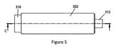
図5は、本開示の第2の態様による断熱材302の一例の外部概略図を示し、この断熱材302は、断熱材202の代替として、エアロゾル供給デバイス100の一部でもある。図5は、中空チャンバ316も示す。 FIG. 5 shows an external schematic view of an example of
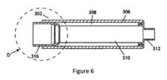
図6は、図2に示された断熱材302の断面C-Cを示す。図5、図6及び図7は、原寸に比例して描かれていない。上で論じられた断熱材202と同様に、断熱材302は、内壁及び外壁306を備えるが、内壁は、第1の加熱要素310及び第2の加熱要素312のそれぞれの少なくとも一部を備える。内壁が第1の加熱要素310、第2の加熱要素312、及び断熱材302の壁として機能するので、エアロゾル供給デバイス100の全体のサイズ及び重量は、別個の加熱要素及び別個の絶縁部材を含むための要件がないときには、低減され得る。上述の断熱材202、302と同様に、内壁及び外壁306は、断熱領域308を取り囲んでおり、この断熱領域は、断熱領域308の外側よりも低い圧力に排気されている。上で論じられた断熱材202、302と同様に、第1の加熱要素310と第2の加熱要素312は、任意の適切な手段で接合されてもよい。ただし、第1の加熱要素310及び第2の加熱要素312は内壁の少なくとも一部を構成するので、第1の加熱要素310と第2の加熱要素312を接合する手段は、外気が断熱領域に漏れ込むのを防止するのに適していなければならない。いくつかの例では、第1の加熱要素310と第2の加熱要素312は互いに一体化されている。断熱領域308の圧力は、10-1~10-7torrの範囲であってもよく、10-3torr以下の圧力が特に有利であると考えられる。いくつかの例では、断熱領域308の圧力は真空であると考えられる。断熱材302の内壁及び外壁306を備える構成要素は、これらに対して断熱領域308と断熱領域308の外部の領域との間の圧力差により作用するいかなる力にも耐えるのに十分な強度があり、断熱材302が内側につぶれることを防止する。ガス吸収材料が、断熱領域308内の比較的低い圧力を維持するために、又はその生成を助けるために断熱領域308に使用されてもよい。FIG. 6 shows a cross section CC of the
図6に示される例では、第2の加熱要素312は、断熱領域308を囲むために外壁306に接合される。このような例では、第2の加熱要素312は、溶接、ろう付け、又は接着剤を用いるなどの、任意の適切な手段によって外壁306に接合される。上で論じられた第1の加熱要素310と第2の加熱要素312との接合と同様に、第2の加熱要素312と外壁306を接合する手段は、外気が断熱領域308に漏れ込むのを防止するのに適していなければならない。この特定の構成体は、本開示の第2の態様のすべての例に存在するとは限らないことがある。例えば、第2の加熱要素312は、中空チャンバ316及び第1の加熱要素310に接合されてもよく、中空チャンバ316及び第1の加熱要素310のそれぞれが、断熱領域を囲むために外壁306に接合されている。すべての例において、断熱領域を囲む構成要素間に形成されるいずれの接合部も、外気が断熱領域308に漏れ込むのを防ぐのに適しているように選択されるべきであることを理解されたい。 In the example shown in FIG. 6, the
図6に示された例は、第1の加熱要素310及び外壁306が中空チャンバ316の一部分を囲んでいること、及び中空チャンバ316が、断熱領域308内に捕捉された、断熱領域308を閉鎖する構成要素の1つであることを示している。このような構成体は、本開示の第2の態様による1つの可能な選択肢の単なる例である。中空チャンバ316は、いくつかの例ではこのようにして含まれないことがあることを理解されたい。さらに、中空チャンバ316が含まれるいくつかの例では、外壁306は、中空チャンバ316が断熱領域308に突き出ないように第1の加熱要素310に直接接合されてもよい。こうすることは、断熱領域308を包含することに要する構成要素の数を減少させるので有利であり得る。こうすることで、製造プロセスを単純化することもでき、エアロゾル供給デバイス100の耐用期間中に、外気が断熱領域308に漏れ込むことを防止する助けになり得る。 The example shown in FIG. 6 shows that the
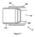
図7は、図6に特定されている断面Dの拡大図である。図7に示された拡大図は、図6に示されたように、第1の加熱要素310、外壁306及び中空チャンバ316からなる構成体をより明確に示す。図6に示され、上で詳細に論じられた断熱領域308もまた、より明確に図7に示されており、この例では、第1の加熱要素310と、外壁306及び中空チャンバ316の一部分との間に配置されている。 FIG. 7 is an enlarged view of section D identified in FIG. The enlarged view shown in FIG. 7 more clearly shows the arrangement of
図6に戻ると、外壁306は、第1の加熱要素310の全長に沿って延びているように示されている。しかし、一代替例では、外壁306は、第1の加熱要素310の長さに沿って部分的に延びるだけでもよい。すなわち、外壁306は、断熱が第1の加熱要素310の一部分のまわりだけで行われ得るように、第1の加熱要素310の一部にだけ沿って延びていてもよい。第1の加熱要素310の長さに沿って一部にだけ延びる外壁306を設けることは、エアロゾル供給デバイス100の全体のサイズがさらに低減されることを可能にすることができる。外壁306と第1の加熱要素310は、互いに同軸であるように示されているが、これは必須ではない。第1の加熱要素310に関するこの段落の記述のそれぞれは、第2の加熱要素312にも同様に当てはまり得ることを理解されたい。しかし、すべての例において、外壁306は、加熱要素及び外壁306からなる特定の構成体にかかわらず、第1の加熱要素310及び第2の加熱要素321の少なくとも一部のまわりに延びる。 Returning to FIG. 6,
上で論じられた断熱材202と同様に、第1の加熱要素310及び第2の加熱要素312は、上で論じられたように、すなわち、変動磁場を侵入させることによって、抵抗加熱によって、及び/又は伝導によって加熱されることが可能である。第1の加熱要素310及び第2の加熱要素312に対する材料要件は、上で論じられたものと同様であり、選ばれた材料は、断熱308への外気の侵入を防止することができなければならない(例えば、非多孔質でなければならない)という追加の要件がある。さらに、選ばれた材料は、断熱領域308と断熱領域308の外部の領域との間の圧力差により第1の加熱要素310及び第2の加熱要素312に対して作用するいかなる力にも耐える十分な強度を有して、断熱材302が内側につぶれることを防止しなければならない。 Similar to the
外壁306に対する材料要件は、上で論じられた外壁206の材料要件と同様である。内壁は、感受性材料及び/又は導電性材料から作られるべきである。中空チャンバ316に対する材料要件は、上で論じられた中空チャンバ216の材料要件と同様であり、中空チャンバ316の少なくとも一部分が断熱領域308を囲むことに関与する例では、選ばれる材料は、断熱308の中への外気の侵入を防止することができなければならない(例えば、非多孔質でなければならない)という追加の要件がある。 The material requirements for
本開示の第3の態様では、本開示の第1又は第2の態様による装置と、使用時に断熱材の内壁の加熱ゾーン内に少なくとも部分的に配置されるエアロゾル生成材料とを備える、エアロゾル供給システムについて説明している。 In a third aspect of the disclosure, an aerosol supply comprising an apparatus according to the first or second aspect of the disclosure and an aerosol-generating material that, in use, is disposed at least partially within the heating zone of the inner wall of the insulation. Explains the system.
上記の実施形態は、本発明の例示的なものとして理解されたい。本発明のさらなる実施形態が想起される。いずれか1つの実施形態に関して説明されたいずれかの機能は単独で、又は説明された他の特徴と一緒に使用されてもよく、また、諸実施形態のうちのいずれか他のものの、又は実施形態のうちのいずれか他のものの任意の組合せの、1つ又は複数の機能と一緒に使用されてもよいと理解されたい。さらに、上述されていない均等物及び修正形態もまた、添付の特許請求の範囲に定義されている本発明の範囲から逸脱することなく使用されてもよい。 The embodiments described above are to be understood as illustrative of the invention. Further embodiments of the invention are envisioned. Any features described with respect to any one embodiment may be used alone or in conjunction with other features described, and may also be used in the implementation of any other of the embodiments. It is to be understood that any combination of any other of the forms may be used with one or more functions. Furthermore, equivalents and modifications not described above may also be used without departing from the scope of the invention as defined in the appended claims.
Claims (22)
Translated fromJapanese前記エアロゾル生成材料を含む消耗品の少なくとも一部分を受け入れるための加熱ゾーンを少なくとも部分的に画定する第1の加熱要素と、
前記第1の加熱要素の軸線方向端部から前記加熱ゾーンを越えて延びる第2の加熱要素と、
断熱材であり、
内壁、
外壁、並びに
前記内壁及び前記外壁で巻かれた断熱領域で、前記断熱領域が、前記断熱領域の外部よりも低い圧力に排気されている、断熱領域を備える、断熱材と
を具備し、
前記断熱材が、前記第1の加熱要素の少なくとも一部及び前記第2の加熱要素の少なくとも一部のまわりに延びるように配置されている、非燃焼式エアロゾル供給デバイス。A non-combustion aerosol delivery device for heating an aerosol-generating material to volatilize at least one component of the aerosol-generating material, the device comprising:
a first heating element at least partially defining a heating zone for receiving at least a portion of the consumable including the aerosol-generating material;
a second heating element extending beyond the heating zone from an axial end of the first heating element;
It is an insulating material,
inner wall,
an outer wall, and an insulating region wrapped around the inner wall and the outer wall, the insulating region being evacuated to a lower pressure than outside the insulating region;
A non-combustion aerosol delivery device, wherein the insulation is arranged to extend around at least a portion of the first heating element and at least a portion of the second heating element.
前記エアロゾル生成材料を含む消耗品の少なくとも一部分を受け入れるための加熱ゾーンを少なくとも部分的に画定する第1の加熱要素と、
前記第1の加熱要素の軸線方向端部から前記加熱ゾーンを越えて延びる第2の加熱要素と、
断熱材であり、
内壁、
外壁、並びに
前記内壁及び前記外壁で巻かれた断熱領域で、前記断熱領域が、前記断熱領域の外部よりも低い圧力に排気されている、断熱領域を備える、断熱材と
を具備し、前記内壁が、前記第1の加熱要素及び前記第2の加熱要素のそれぞれの少なくとも一部を備える、非燃焼式エアロゾル供給デバイス。A non-combustion aerosol delivery device for heating an aerosol-generating material to volatilize at least one component of the aerosol-generating material, the device comprising:
a first heating element at least partially defining a heating zone for receiving at least a portion of the consumable including the aerosol-generating material;
a second heating element extending beyond the heating zone from an axial end of the first heating element;
It is an insulating material,
inner wall,
an outer wall, and an insulating material having an insulating region wrapped around the inner wall and the outer wall, the insulating region being evacuated to a lower pressure than the outside of the insulating region; a non-combustion aerosol delivery device comprising at least a portion of each of the first heating element and the second heating element.
使用時に、前記第1及び/又は第2の加熱要素の前記加熱ゾーン内に少なくとも部分的に配置されるエアロゾル生成材料と
を備える、非燃焼式エアロゾル供給システム。A device according to any one of claims 1 to 20,
an aerosol-generating material that, in use, is at least partially located within the heating zone of the first and/or second heating element.
Priority Applications (1)
| Application Number | Priority Date | Filing Date | Title |
|---|---|---|---|
| JP2025004175AJP2025069179A (en) | 2020-09-14 | 2025-01-10 | Aerosol Generation System |
Applications Claiming Priority (3)
| Application Number | Priority Date | Filing Date | Title |
|---|---|---|---|
| GB2014445.7AGB2598898A (en) | 2020-09-14 | 2020-09-14 | Aerosol generation system |
| GB2014445.7 | 2020-09-14 | ||
| PCT/EP2021/075117WO2022053686A1 (en) | 2020-09-14 | 2021-09-13 | Aerosol generation system |
Related Child Applications (1)
| Application Number | Title | Priority Date | Filing Date |
|---|---|---|---|
| JP2025004175ADivisionJP2025069179A (en) | 2020-09-14 | 2025-01-10 | Aerosol Generation System |
Publications (1)
| Publication Number | Publication Date |
|---|---|
| JP2023541895Atrue JP2023541895A (en) | 2023-10-04 |
Family
ID=73149758
Family Applications (2)
| Application Number | Title | Priority Date | Filing Date |
|---|---|---|---|
| JP2023516141APendingJP2023541895A (en) | 2020-09-14 | 2021-09-13 | Aerosol generation system |
| JP2025004175APendingJP2025069179A (en) | 2020-09-14 | 2025-01-10 | Aerosol Generation System |
Family Applications After (1)
| Application Number | Title | Priority Date | Filing Date |
|---|---|---|---|
| JP2025004175APendingJP2025069179A (en) | 2020-09-14 | 2025-01-10 | Aerosol Generation System |
Country Status (6)
| Country | Link |
|---|---|
| US (1) | US20230354899A1 (en) |
| EP (1) | EP4210525A1 (en) |
| JP (2) | JP2023541895A (en) |
| KR (1) | KR20230053624A (en) |
| GB (1) | GB2598898A (en) |
| WO (1) | WO2022053686A1 (en) |
Families Citing this family (1)
| Publication number | Priority date | Publication date | Assignee | Title |
|---|---|---|---|---|
| GB202303638D0 (en)* | 2023-03-13 | 2023-04-26 | Nicoventures Trading Ltd | Aerosol delivery devices, systems, consumables and methods |
Citations (11)
| Publication number | Priority date | Publication date | Assignee | Title |
|---|---|---|---|---|
| US20120260927A1 (en)* | 2010-11-19 | 2012-10-18 | Qiuming Liu | Electronic cigarette, electronic cigarette smoke capsule and atomization device thereof |
| JP2014525251A (en)* | 2011-09-06 | 2014-09-29 | ブリティッシュ アメリカン タバコ (インヴェストメンツ) リミテッド | Smoking material heating |
| JP2016534730A (en)* | 2013-10-29 | 2016-11-10 | ブリティッシュ アメリカン タバコ (インヴェストメンツ) リミテッドBritish American Tobacco (Investments) Limited | Device for heating smoking material |
| US20180070639A1 (en)* | 2016-09-14 | 2018-03-15 | Shenzhen First Union Technology Co., Ltd. | Atomizing device and electronic cigarette having same |
| JP2018522551A (en)* | 2015-06-26 | 2018-08-16 | ブリティッシュ アメリカン タバコ (インヴェストメンツ) リミテッドBritish American Tobacco (Investments) Limited | Smoking material heating device |
| WO2019053268A1 (en)* | 2017-09-15 | 2019-03-21 | British American Tobacco (Investments) Limited | Apparatus for heating smokable material |
| JP2019521656A (en)* | 2016-05-13 | 2019-08-08 | ブリティッシュ アメリカン タバコ (インヴェストメンツ) リミテッドBritish American Tobacco (Investments) Limited | Device for heating smoking material |
| CN110338473A (en)* | 2019-08-21 | 2019-10-18 | 深圳市吉迩科技有限公司 | Electronic cigarette heater and electronic cigarette set with heat insulation function |
| JP2019535283A (en)* | 2016-11-22 | 2019-12-12 | フィリップ・モーリス・プロダクツ・ソシエテ・アノニム | Induction heating apparatus, aerosol generation system including induction heating apparatus, and method of operating the same |
| JP2020511990A (en)* | 2017-03-31 | 2020-04-23 | フィリップ・モーリス・プロダクツ・ソシエテ・アノニム | Susceptor assembly for induction heating of an aerosol-forming substrate |
| JP2020519266A (en)* | 2017-05-10 | 2020-07-02 | フィリップ・モーリス・プロダクツ・ソシエテ・アノニム | Aerosol-generating articles, devices and systems for use with multiple aerosol-forming substrates |
Family Cites Families (3)
| Publication number | Priority date | Publication date | Assignee | Title |
|---|---|---|---|---|
| CN204070517U (en)* | 2014-04-02 | 2015-01-07 | 深圳市合元科技有限公司 | Baking-type atomizer and the thick film heating parts for baking-type atomizer |
| US20170055583A1 (en)* | 2015-08-31 | 2017-03-02 | British American Tobacco (Investments) Limited | Apparatus for heating smokable material |
| US20210212366A1 (en)* | 2018-08-15 | 2021-07-15 | Nicoventures Trading Limited | Apparatus for heating an article including an aerosolisable medium, a method of manufacturing the apparatus and an aerosolisable material article for use with the apparatus |
- 2020
- 2020-09-14GBGB2014445.7Apatent/GB2598898A/ennot_activeWithdrawn
- 2021
- 2021-09-13JPJP2023516141Apatent/JP2023541895A/enactivePending
- 2021-09-13WOPCT/EP2021/075117patent/WO2022053686A1/ennot_activeCeased
- 2021-09-13USUS18/245,203patent/US20230354899A1/enactivePending
- 2021-09-13EPEP21777671.5Apatent/EP4210525A1/enactivePending
- 2021-09-13KRKR1020237008074Apatent/KR20230053624A/enactivePending
- 2025
- 2025-01-10JPJP2025004175Apatent/JP2025069179A/enactivePending
Patent Citations (11)
| Publication number | Priority date | Publication date | Assignee | Title |
|---|---|---|---|---|
| US20120260927A1 (en)* | 2010-11-19 | 2012-10-18 | Qiuming Liu | Electronic cigarette, electronic cigarette smoke capsule and atomization device thereof |
| JP2014525251A (en)* | 2011-09-06 | 2014-09-29 | ブリティッシュ アメリカン タバコ (インヴェストメンツ) リミテッド | Smoking material heating |
| JP2016534730A (en)* | 2013-10-29 | 2016-11-10 | ブリティッシュ アメリカン タバコ (インヴェストメンツ) リミテッドBritish American Tobacco (Investments) Limited | Device for heating smoking material |
| JP2018522551A (en)* | 2015-06-26 | 2018-08-16 | ブリティッシュ アメリカン タバコ (インヴェストメンツ) リミテッドBritish American Tobacco (Investments) Limited | Smoking material heating device |
| JP2019521656A (en)* | 2016-05-13 | 2019-08-08 | ブリティッシュ アメリカン タバコ (インヴェストメンツ) リミテッドBritish American Tobacco (Investments) Limited | Device for heating smoking material |
| US20180070639A1 (en)* | 2016-09-14 | 2018-03-15 | Shenzhen First Union Technology Co., Ltd. | Atomizing device and electronic cigarette having same |
| JP2019535283A (en)* | 2016-11-22 | 2019-12-12 | フィリップ・モーリス・プロダクツ・ソシエテ・アノニム | Induction heating apparatus, aerosol generation system including induction heating apparatus, and method of operating the same |
| JP2020511990A (en)* | 2017-03-31 | 2020-04-23 | フィリップ・モーリス・プロダクツ・ソシエテ・アノニム | Susceptor assembly for induction heating of an aerosol-forming substrate |
| JP2020519266A (en)* | 2017-05-10 | 2020-07-02 | フィリップ・モーリス・プロダクツ・ソシエテ・アノニム | Aerosol-generating articles, devices and systems for use with multiple aerosol-forming substrates |
| WO2019053268A1 (en)* | 2017-09-15 | 2019-03-21 | British American Tobacco (Investments) Limited | Apparatus for heating smokable material |
| CN110338473A (en)* | 2019-08-21 | 2019-10-18 | 深圳市吉迩科技有限公司 | Electronic cigarette heater and electronic cigarette set with heat insulation function |
Also Published As
| Publication number | Publication date |
|---|---|
| KR20230053624A (en) | 2023-04-21 |
| EP4210525A1 (en) | 2023-07-19 |
| WO2022053686A1 (en) | 2022-03-17 |
| US20230354899A1 (en) | 2023-11-09 |
| JP2025069179A (en) | 2025-04-30 |
| GB202014445D0 (en) | 2020-10-28 |
| GB2598898A (en) | 2022-03-23 |
Similar Documents
| Publication | Publication Date | Title |
|---|---|---|
| JP2021523707A (en) | Aerosol-producing articles, methods for producing aerosol-producing articles, and aerosol-producing systems. | |
| KR20210132184A (en) | Apparatus for an aerosol-generating device | |
| JP2025069179A (en) | Aerosol Generation System | |
| JP7607752B2 (en) | Aerosol Delivery Device | |
| EP4445779A1 (en) | Aerosol provision device | |
| JP7337947B2 (en) | Aerosol delivery device | |
| US20250057239A1 (en) | Aerosol provision device | |
| JP7618785B2 (en) | Aerosol Generation System | |
| KR102807298B1 (en) | Aerosol generating device | |
| JP2025066733A (en) | Aerosol Delivery Device | |
| US20220183375A1 (en) | Aerosol provision device | |
| JP7701437B2 (en) | Aerosol Delivery Device | |
| US20230354903A1 (en) | Aerosol provision device | |
| CN116963623A (en) | Equipment for heating aerosolizable materials | |
| JP7608597B2 (en) | Method for manufacturing thermal insulation material | |
| US20250057238A1 (en) | Aerosol provision device | |
| US20250057236A1 (en) | Aerosol provision device | |
| US20240138480A1 (en) | Apparatus for heating aerosolisable material | |
| JP2024544829A (en) | Induction heating assembly for an aerosol generating device - Patent Application 20070123633 | |
| EA041380B1 (en) | AEROSOL GENERATING ARTICLE, METHOD OF MANUFACTURING AEROSOL GENERATING ARTICLE AND AEROSOL GENERATING SYSTEM |
Legal Events
| Date | Code | Title | Description |
|---|---|---|---|
| A621 | Written request for application examination | Free format text:JAPANESE INTERMEDIATE CODE: A621 Effective date:20230508 | |
| A977 | Report on retrieval | Free format text:JAPANESE INTERMEDIATE CODE: A971007 Effective date:20240514 | |
| A131 | Notification of reasons for refusal | Free format text:JAPANESE INTERMEDIATE CODE: A131 Effective date:20240528 | |
| A02 | Decision of refusal | Free format text:JAPANESE INTERMEDIATE CODE: A02 Effective date:20240910 |