JP2023538213A - Systems, devices, and methods for ablation and defunctionalization of the gallbladder - Google Patents
Systems, devices, and methods for ablation and defunctionalization of the gallbladderDownload PDFInfo
- Publication number
- JP2023538213A JP2023538213AJP2022581352AJP2022581352AJP2023538213AJP 2023538213 AJP2023538213 AJP 2023538213AJP 2022581352 AJP2022581352 AJP 2022581352AJP 2022581352 AJP2022581352 AJP 2022581352AJP 2023538213 AJP2023538213 AJP 2023538213A
- Authority
- JP
- Japan
- Prior art keywords
- ablation
- lumen
- gallbladder
- shaft
- nozzle
- Prior art date
- Legal status (The legal status is an assumption and is not a legal conclusion. Google has not performed a legal analysis and makes no representation as to the accuracy of the status listed.)
- Pending
Links
Images


Classifications
- A—HUMAN NECESSITIES
- A61—MEDICAL OR VETERINARY SCIENCE; HYGIENE
- A61B—DIAGNOSIS; SURGERY; IDENTIFICATION
- A61B18/00—Surgical instruments, devices or methods for transferring non-mechanical forms of energy to or from the body
- A61B18/02—Surgical instruments, devices or methods for transferring non-mechanical forms of energy to or from the body by cooling, e.g. cryogenic techniques
- A61B18/0218—Surgical instruments, devices or methods for transferring non-mechanical forms of energy to or from the body by cooling, e.g. cryogenic techniques with open-end cryogenic probe, e.g. for spraying fluid directly on tissue or via a tissue-contacting porous tip
- A—HUMAN NECESSITIES
- A61—MEDICAL OR VETERINARY SCIENCE; HYGIENE
- A61B—DIAGNOSIS; SURGERY; IDENTIFICATION
- A61B18/00—Surgical instruments, devices or methods for transferring non-mechanical forms of energy to or from the body
- A61B18/04—Surgical instruments, devices or methods for transferring non-mechanical forms of energy to or from the body by heating
- A61B18/12—Surgical instruments, devices or methods for transferring non-mechanical forms of energy to or from the body by heating by passing a current through the tissue to be heated, e.g. high-frequency current
- A61B18/1206—Generators therefor
- A—HUMAN NECESSITIES
- A61—MEDICAL OR VETERINARY SCIENCE; HYGIENE
- A61B—DIAGNOSIS; SURGERY; IDENTIFICATION
- A61B17/00—Surgical instruments, devices or methods
- A61B17/00234—Surgical instruments, devices or methods for minimally invasive surgery
- A61B2017/00292—Surgical instruments, devices or methods for minimally invasive surgery mounted on or guided by flexible, e.g. catheter-like, means
- A61B2017/00336—Surgical instruments, devices or methods for minimally invasive surgery mounted on or guided by flexible, e.g. catheter-like, means with a protective sleeve, e.g. retractable or slidable
- A—HUMAN NECESSITIES
- A61—MEDICAL OR VETERINARY SCIENCE; HYGIENE
- A61B—DIAGNOSIS; SURGERY; IDENTIFICATION
- A61B18/00—Surgical instruments, devices or methods for transferring non-mechanical forms of energy to or from the body
- A61B2018/00005—Cooling or heating of the probe or tissue immediately surrounding the probe
- A61B2018/00041—Heating, e.g. defrosting
- A—HUMAN NECESSITIES
- A61—MEDICAL OR VETERINARY SCIENCE; HYGIENE
- A61B—DIAGNOSIS; SURGERY; IDENTIFICATION
- A61B18/00—Surgical instruments, devices or methods for transferring non-mechanical forms of energy to or from the body
- A61B2018/00053—Mechanical features of the instrument of device
- A61B2018/0016—Energy applicators arranged in a two- or three dimensional array
- A—HUMAN NECESSITIES
- A61—MEDICAL OR VETERINARY SCIENCE; HYGIENE
- A61B—DIAGNOSIS; SURGERY; IDENTIFICATION
- A61B18/00—Surgical instruments, devices or methods for transferring non-mechanical forms of energy to or from the body
- A61B2018/00053—Mechanical features of the instrument of device
- A61B2018/00214—Expandable means emitting energy, e.g. by elements carried thereon
- A61B2018/0022—Balloons
- A—HUMAN NECESSITIES
- A61—MEDICAL OR VETERINARY SCIENCE; HYGIENE
- A61B—DIAGNOSIS; SURGERY; IDENTIFICATION
- A61B18/00—Surgical instruments, devices or methods for transferring non-mechanical forms of energy to or from the body
- A61B2018/00053—Mechanical features of the instrument of device
- A61B2018/00273—Anchoring means for temporary attachment of a device to tissue
- A61B2018/00279—Anchoring means for temporary attachment of a device to tissue deployable
- A61B2018/00285—Balloons
- A—HUMAN NECESSITIES
- A61—MEDICAL OR VETERINARY SCIENCE; HYGIENE
- A61B—DIAGNOSIS; SURGERY; IDENTIFICATION
- A61B18/00—Surgical instruments, devices or methods for transferring non-mechanical forms of energy to or from the body
- A61B2018/00315—Surgical instruments, devices or methods for transferring non-mechanical forms of energy to or from the body for treatment of particular body parts
- A61B2018/00529—Liver
- A61B2018/00535—Biliary tract
- A—HUMAN NECESSITIES
- A61—MEDICAL OR VETERINARY SCIENCE; HYGIENE
- A61B—DIAGNOSIS; SURGERY; IDENTIFICATION
- A61B18/00—Surgical instruments, devices or methods for transferring non-mechanical forms of energy to or from the body
- A61B2018/00571—Surgical instruments, devices or methods for transferring non-mechanical forms of energy to or from the body for achieving a particular surgical effect
- A61B2018/00577—Ablation
- A—HUMAN NECESSITIES
- A61—MEDICAL OR VETERINARY SCIENCE; HYGIENE
- A61B—DIAGNOSIS; SURGERY; IDENTIFICATION
- A61B18/00—Surgical instruments, devices or methods for transferring non-mechanical forms of energy to or from the body
- A61B2018/00636—Sensing and controlling the application of energy
- A61B2018/00642—Sensing and controlling the application of energy with feedback, i.e. closed loop control
- A—HUMAN NECESSITIES
- A61—MEDICAL OR VETERINARY SCIENCE; HYGIENE
- A61B—DIAGNOSIS; SURGERY; IDENTIFICATION
- A61B18/00—Surgical instruments, devices or methods for transferring non-mechanical forms of energy to or from the body
- A61B2018/00636—Sensing and controlling the application of energy
- A61B2018/00696—Controlled or regulated parameters
- A61B2018/00744—Fluid flow
- A—HUMAN NECESSITIES
- A61—MEDICAL OR VETERINARY SCIENCE; HYGIENE
- A61B—DIAGNOSIS; SURGERY; IDENTIFICATION
- A61B18/00—Surgical instruments, devices or methods for transferring non-mechanical forms of energy to or from the body
- A61B2018/00636—Sensing and controlling the application of energy
- A61B2018/00773—Sensed parameters
- A61B2018/00791—Temperature
- A—HUMAN NECESSITIES
- A61—MEDICAL OR VETERINARY SCIENCE; HYGIENE
- A61B—DIAGNOSIS; SURGERY; IDENTIFICATION
- A61B18/00—Surgical instruments, devices or methods for transferring non-mechanical forms of energy to or from the body
- A61B18/02—Surgical instruments, devices or methods for transferring non-mechanical forms of energy to or from the body by cooling, e.g. cryogenic techniques
- A61B2018/0212—Surgical instruments, devices or methods for transferring non-mechanical forms of energy to or from the body by cooling, e.g. cryogenic techniques using an instrument inserted into a body lumen, e.g. catheter
- A—HUMAN NECESSITIES
- A61—MEDICAL OR VETERINARY SCIENCE; HYGIENE
- A61B—DIAGNOSIS; SURGERY; IDENTIFICATION
- A61B90/00—Instruments, implements or accessories specially adapted for surgery or diagnosis and not covered by any of the groups A61B1/00 - A61B50/00, e.g. for luxation treatment or for protecting wound edges
- A61B90/06—Measuring instruments not otherwise provided for
- A61B2090/064—Measuring instruments not otherwise provided for for measuring force, pressure or mechanical tension
- A—HUMAN NECESSITIES
- A61—MEDICAL OR VETERINARY SCIENCE; HYGIENE
- A61B—DIAGNOSIS; SURGERY; IDENTIFICATION
- A61B2218/00—Details of surgical instruments, devices or methods for transferring non-mechanical forms of energy to or from the body
- A61B2218/001—Details of surgical instruments, devices or methods for transferring non-mechanical forms of energy to or from the body having means for irrigation and/or aspiration of substances to and/or from the surgical site
- A61B2218/007—Aspiration
Landscapes
- Health & Medical Sciences (AREA)
- Surgery (AREA)
- Life Sciences & Earth Sciences (AREA)
- Nuclear Medicine, Radiotherapy & Molecular Imaging (AREA)
- Biomedical Technology (AREA)
- Engineering & Computer Science (AREA)
- Otolaryngology (AREA)
- Heart & Thoracic Surgery (AREA)
- Medical Informatics (AREA)
- Molecular Biology (AREA)
- Animal Behavior & Ethology (AREA)
- General Health & Medical Sciences (AREA)
- Public Health (AREA)
- Veterinary Medicine (AREA)
- Surgical Instruments (AREA)
Abstract
Translated fromJapanese
Description
Translated fromJapanese (関連出願の相互参照)
本出願は、2020年8月14日に出願された「SYSTEMS,DEVICES,AND METHODS FOR ABLATION AND DEFUNCITONALIZATION OF A GALLBLADDER」と題する、米国仮出願第63/066,005号の優先権及び利益を主張し、その開示は、参照によりその全体が本明細書に組み込まれる。(Cross reference to related applications)
This application is filed in U.S. Provisional Application No. 63/066,005, entitled "SYSTEMS, DEVICES, AND METHODS FOR ABLATION AND DEFUNCITONALIZATION OF A GALLBLADDER," filed on August 14, 2020. claim priority and interest; , the disclosure of which is incorporated herein by reference in its entirety.
(発明の分野)
本開示は、胆嚢のアブレーション及び非機能化のためのデバイス及び方法に関する。(Field of invention)
The present disclosure relates to devices and methods for ablation and defunctionalization of the gallbladder.
心臓学、腫瘍学、一般外科学、胃腸病学、皮膚科学、及びインターベンショナルラジオロジーにおいて使用されるものなどの医療アブレーション技術は、局所組織標的に焦点を当てており、高度のアブレーション深度制御を提供するが、体内の大型高表面積(high-surface area、HSA)組織アブレーション標的に対して有効でも実用的でもない場合がある。冷凍アブレーション技術は、HSA組織アブレーションのためのプラットフォームを提供するために一般的な寒剤噴霧を活用するが、胆嚢などの閉鎖内腔内にエネルギーを安全かつ効果的に送達することに関連付けられた特定の欠点を有する。例えば、アブレーション処置中の氷の蓄積又は他の厄介な問題は、損傷及び/又は無効なアブレーションにつながる可能性がある。したがって、既存のアブレーションシステムの欠点に対処するためのシステム、デバイス、及び方法を有することが望ましい。 Medical ablation techniques, such as those used in cardiology, oncology, general surgery, gastroenterology, dermatology, and interventional radiology, focus on local tissue targets and require advanced ablation depth control. However, it may not be effective or practical for large high-surface area (HSA) tissue ablation targets within the body. Cryoablation technology utilizes common cryogen sprays to provide a platform for HSA tissue ablation, but specific challenges associated with safely and effectively delivering energy within closed lumens such as the gallbladder. It has the following disadvantages. For example, ice buildup or other nuisances during an ablation procedure can lead to damage and/or ineffective ablation. Therefore, it would be desirable to have systems, devices, and methods that address the shortcomings of existing ablation systems.
本開示は、胆嚢のアブレーション及び非機能化のためのデバイス及び方法に関する。いくつかの実施形態では、装置は、管腔を画定し、対象の体内腔内に配設可能な遠位部分を有するシャフトであって、遠位部分上に配設され、管腔と流体連通している複数の開口部を画定し、アブレーション媒体を体内腔内に送達するように構成されたノズルを含む、シャフトと、ノズルの周りに配設された拡張可能な構造体であって、体内腔内で拡張状態に移行するように構成され、拡張可能な構造体が拡張状態にあるときに、(1)ノズルを体内腔内の組織から少なくとも所定の距離だけ離して位置決めし、(2)アブレーション媒体が拡張可能な構造体を通して体内腔内の組織と接触してアブレーションすることを可能にするように構成されている複数の細長い部材を含む、拡張可能な構造体と、を含む。 The present disclosure relates to devices and methods for ablation and defunctionalization of the gallbladder. In some embodiments, the device is a shaft having a distal portion that defines a lumen and is positionable within a body lumen of a subject, the shaft being disposed on the distal portion and in fluid communication with the lumen. a shaft and an expandable structure disposed about the nozzle, the structure including a nozzle defining a plurality of openings in the body and configured to deliver an ablation medium into the body lumen; configured to transition to an expanded state within the body lumen, when the expandable structure is in the expanded state, (1) positioning the nozzle at least a predetermined distance from tissue within the body lumen; an expandable structure including a plurality of elongated members configured to allow an ablation medium to contact and ablate tissue within the body lumen through the expandable structure.
いくつかの実施形態では、装置は、対象の体内腔内に配設可能な遠位端を有する外側シャフトであって、外側シャフトが、第1の管腔及び第1の管腔と流体連通している複数の排出開口部を画定し、複数の排出開口部及び第1の管腔が、体内腔からアブレーション媒体を排出するように集合的に構成され、外側シャフトが、(1)外側シャフトの遠位端上に配設され、(2)複数の排出開口部を取り囲み、デブリが複数の排出開口部を詰まらせることを防止するように拡張状態に移行するように構成された拡張可能な構造体を含む、外側シャフトと、第1の管腔内に配設可能であり、外側シャフトの遠位に延在可能なノズルを有する内側シャフトであって、内側シャフトが、ノズルと流体連通している第2の管腔を画定し、第2の管腔は、ノズルが体内腔全体にアブレーション媒体を散布し、体内腔内の組織と接触してアブレーションすることができるように、アブレーション媒体をノズルに送達するように構成されている、内側シャフトと、を含む。 In some embodiments, the device is an outer shaft having a distal end disposed within a body lumen of a subject, the outer shaft being in fluid communication with a first lumen and the first lumen. the outer shaft defines a plurality of evacuation openings, the plurality of evacuation openings and the first lumen are collectively configured to eject the ablation medium from the body lumen; an expandable structure disposed on the distal end and (2) configured to surround the plurality of evacuation openings and transition to an expanded state to prevent debris from clogging the plurality of evacuation openings; an outer shaft including a body and an inner shaft having a nozzle disposed within the first lumen and extendable distally of the outer shaft, the inner shaft being in fluid communication with the nozzle; a second lumen configured to distribute the ablation medium through the nozzle such that the nozzle can distribute the ablation medium throughout the body lumen and contact and ablate tissue within the body lumen; an inner shaft configured to deliver to.
いくつかの実施形態では、方法は、アクセスシースを対象の体内腔内に保持するために、アブレーションカテーテルの外側シャフトの遠位端上に配設された第1の拡張可能な構造体を拡張状態に移行させることであって、外側シャフトの遠位端が、体内腔内に配設され、外側シャフトが、第1の管腔を画定する、移行させることと、内側シャフトの遠位端を第1の管腔を介して体内腔内に前進させることであって、内側シャフトが、第2の管腔を画定し、ノズルと、内側シャフトの遠位端上に配設された第2の拡張可能な構造体と、を含む、前進させることと、第2の拡張可能な構造体を拡張状態に移行させて、ノズルを体内腔内の組織から少なくとも所定の距離に位置決めすることと、第2の管腔を介して、アブレーション流体をノズルに搬送することと、アブレーション流体が、体内腔内の組織と接触して、組織をアブレーションするアブレーションガスに転移するように、ノズルからアブレーション流体を分注することと、を含む。 In some embodiments, the method includes deploying a first expandable structure disposed on the distal end of the outer shaft of the ablation catheter in an expanded state to retain the access sheath within the body lumen of the subject. transitioning the distal end of the outer shaft to a body lumen, the outer shaft defining a first lumen; and transitioning the distal end of the inner shaft to a first lumen. advancing a body lumen through a first lumen, the inner shaft defining a second lumen, a nozzle and a second dilation disposed on a distal end of the inner shaft; moving the second expandable structure into an expanded state to position the nozzle at least a predetermined distance from tissue within the body lumen; conveying an ablation fluid to a nozzle through a lumen of the body and dispensing the ablation fluid from the nozzle such that the ablation fluid contacts tissue within the body lumen and transfers to an ablation gas that ablates the tissue. and include.
本開示は、例えば、胆嚢内腔などの体内腔をアブレーションするためのアブレーションシステム、デバイス、及び方法に関する。いくつかの実施形態では、本明細書に記載のシステム、デバイス、及び方法は、組織アブレーションのための冷凍アブレーションデバイスに関する。いくつかの実施形態では、本明細書に記載のシステム、デバイス、及び方法は、アブレーション媒体(例えば、低温アブレーション媒体)を対象領域(例えば、胆嚢内腔の内側を覆う組織)上に安全に、効果的に、かつ均一に分散させるように設計される、例えば、カテーテルベースの冷凍アブレーションデバイスのためのアブレーション媒体解放弁に関する。いくつかの実施形態では、本明細書に記載のシステム、デバイス、及び方法は、センサデータ、例えば、圧力及び/又は温度データに基づいて、アブレーションシステムの動作を制御することに関する。いくつかの実施形態では、本明細書に記載のシステム、デバイス、及び方法は、体内腔(例えば、胆嚢内腔)及び/又は体内腔内に送達されているアブレーション媒体の特性又は状態を追跡するために、センサを含み、かつ/又は(例えば、1つ以上のプローブの)センサと共に使用することができる。冷凍アブレーションデバイスを含むアブレーションシステムの好適な構成要素の例は、2019年2月7日に出願された「GALLBLADDER DEFUNCITONALIZATION DEVICES AND METHODS」と題する、国際出願第US2019/017112号、及び2020年8月7日に出願された「SYSTEMS,DEVICES,AND METHODS FOR ABLATION AND DEFUNCTIONALIZATION OF A GALLBLADDER」と題する、国際出願第US2020/045436号に記載されており、その各々の全体が参照により組み込まれる。 The present disclosure relates to ablation systems, devices, and methods for ablating body lumens, such as, for example, the gallbladder lumen. In some embodiments, the systems, devices, and methods described herein relate to cryoablation devices for tissue ablation. In some embodiments, the systems, devices, and methods described herein safely apply an ablation medium (e.g., cryoablation medium) onto an area of interest (e.g., tissue lining the gallbladder lumen). The present invention relates to an ablation media release valve for, for example, a catheter-based cryoablation device, designed for effective and uniform dispersion. In some embodiments, the systems, devices, and methods described herein relate to controlling operation of an ablation system based on sensor data, such as pressure and/or temperature data. In some embodiments, the systems, devices, and methods described herein track properties or conditions of a body lumen (e.g., gallbladder lumen) and/or of an ablation medium being delivered within a body lumen. The probe may include and/or be used with a sensor (eg, of one or more probes) for purposes. Examples of suitable components of ablation systems including cryoablation devices are disclosed in International Application No. US 2019/017112, entitled “GALLBLADDER DEFUNCITONALIZATION DEVICES AND METHODS,” filed February 7, 2019, and August 7, 2020. International Application No. US 2020/045436 entitled “SYSTEMS, DEVICES, AND METHODS FOR ABLATION AND DEFUNCTIONALIZATION OF A GALLBLADDER” filed on is incorporated by reference.
胆石は、アメリカ人の間で最も一般的な胃腸障害の1つである。胆石は、肝臓によって分泌され、胆嚢に貯蔵される流体である胆汁が過飽和になると形成される。胆石は多くの人に問題を引き起こさないが、胆嚢管、すなわち、胆嚢の出口を遮断し、胆嚢が空になるのを妨げることがある。場合によっては、閉塞は、疼痛、炎症、及び感染をもたらす。他の点では健康な患者において、胆石症は、胆嚢の外科的除去によって治療される。しかしながら、外科的処置に関連付けられたリスクは、特定の患者集団においてかなり高い。例えば、5人に1人のメディケア患者が有害な転帰を患うことが示されている。これらの患者に対する非外科的治療の選択肢は限られており、疾患の根本的な原因に対処することなく急性症状を緩和することに焦点を当てている。場合によっては、疾患は再発する可能性があり、更なる臨床的リスク及び著しい費用をもたらす。現在、高リスク患者における胆嚢疾患に対する長期的な解決策は存在しない。 Gallstones are one of the most common gastrointestinal disorders among Americans. Gallstones form when bile, a fluid secreted by the liver and stored in the gallbladder, becomes supersaturated. Gallstones do not cause problems for many people, but they can block the cystic duct, the outlet of the gallbladder, and prevent the gallbladder from emptying. In some cases, blockage results in pain, inflammation, and infection. In otherwise healthy patients, cholelithiasis is treated by surgical removal of the gallbladder. However, the risks associated with surgical procedures are considerably higher in certain patient populations. For example, it has been shown that one in five Medicare patients suffers from an adverse outcome. Nonsurgical treatment options for these patients are limited and focus on relieving acute symptoms without addressing the underlying cause of the disease. In some cases, the disease may recur, posing additional clinical risks and significant costs. Currently, there are no long-term solutions for gallbladder disease in high-risk patients.
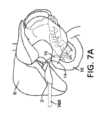
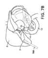
図7A~図7Cに示すように、胆嚢2は、胃腸系における小さな中空器官である。胆道系の盲端管状嚢である胆嚢2は、30ミリリットル(mL)~50mLの貯蔵容量を有するナシ形の器官である。胆嚢は、典型的には、幅が2~3センチメートル(cm)であり、軸方向長さが7~10cmである。胆嚢は、典型的には、3つの部分、すなわち、基底部、体部、及び頸部に分割される。頸部は、ハルトマン嚢として知られる粘膜ひだを含有し、これは、胆石がつかえて胆嚢炎をもたらす一般的な場所である。図7A~図7Cに示すように、胆嚢2は、胆嚢管14内に開口し、右肝管と左肝管とに分岐する共通肝管18によって肝臓8に接続する。胆嚢2は、総胆管16によって小腸10に接続されている。 As shown in FIGS. 7A-7C, the
組織学的に、胆嚢は、漿膜(最外層)、筋層、固有層、及び最内粘膜層を含む4つの層を有する。胆嚢の粘膜層は、胆嚢壁の最内層であり、胆汁を濃縮する。漿膜は、臓側腹膜に由来し、胆嚢の前部基底部、本体、及び頸部を覆う。漿膜の内側では、単一の筋層が固有層を覆う。胆嚢の内腔の内側を覆う粘膜は、ムチンを分泌し、複数のイオンチャネルの作用を介して胆汁を脱水する円柱上皮細胞から構成されている。時折、粘膜の嚢(ロキタンスキー・アショッフ結節として知られている)は、胆嚢壁のより深い層内に延在する。 Histologically, the gallbladder has four layers including the serosa (outermost layer), muscularis, lamina propria, and innermost mucosal layer. The mucosal layer of the gallbladder is the innermost layer of the gallbladder wall and concentrates bile. The serosa originates from the visceral peritoneum and covers the anterior base, body, and neck of the gallbladder. Inside the serosa, a single muscular layer covers the lamina propria. The mucosa lining the lumen of the gallbladder is composed of columnar epithelial cells that secrete mucin and dehydrate bile through the action of multiple ion channels. Occasionally, mucosal sacs (known as Rokitansky-Aschoff nodules) extend into the deeper layers of the gallbladder wall.
胆嚢は、肝臓によって産生される胆汁を貯蔵及び濃縮し、貯蔵された胆汁を小腸内に解放し、小腸において胆汁は食物中の脂肪の消化を助ける。胆汁は、肝臓内の肝細胞によって作られ、その後、肝内管に合体する肝小管に分泌される。これらの管は、収束して左右の肝管を形成し、次いで、これらの肝管は、総胆管に合流する。総胆管は、十二指腸壁内のファーター膨大部のすぐ近位で膵管と接合する。肝細胞によって産生された胆汁は、胆道系を通って十二指腸管腔内に流れ、消化を補助する。 The gallbladder stores and concentrates bile produced by the liver and releases the stored bile into the small intestine, where bile helps digest fats in food. Bile is made by hepatocytes within the liver and is then secreted into hepatic canaliculi that merge into intrahepatic ducts. These ducts converge to form the left and right hepatic ducts, which then join the common bile duct. The common bile duct joins the pancreatic duct just proximal to the ampulla of Vater within the duodenal wall. Bile produced by hepatocytes flows through the biliary system into the duodenal lumen and aids in digestion.
十二指腸管腔内への流れは、オッディ括約筋によってファーター膨大部のレベルで調節される。消化のために胆汁が必要とされない非摂食状態の間、括約筋は閉鎖され、貯蔵のために胆嚢への胆汁の経路指定をもたらす。貯蔵中、胆汁は過飽和になり、胆石及びスラッジ(非常に小さい胆石)の形成のための病巣を提供する。胆石の大部分は、主にコレステロール(典型的には>80%)からなる「褐色石」である。これらの石は脆く、容易に粉砕される傾向がある。少数の石は主にビリルビンである(「黒色石」、<20%コレステロール)であり、より硬いことが多い。混合石は、可変量のビリルビン及びコレステロールを含有する。 Flow into the duodenal lumen is regulated at the level of the ampulla of Vater by the sphincter of Oddi. During non-feeding states, when bile is not required for digestion, the sphincter is closed, resulting in the routing of bile to the gallbladder for storage. During storage, bile becomes supersaturated, providing a nidus for the formation of gallstones and sludge (very small gallstones). The majority of gallstones are "brownstones" consisting primarily of cholesterol (typically >80%). These stones are brittle and tend to shatter easily. A few stones are primarily bilirubin ("black stones", <20% cholesterol) and are often harder. Mixed stones contain variable amounts of bilirubin and cholesterol.
胆嚢の内腔に残る可動性胆石は、様々な病状を引き起こす可能性がある。場合によっては、胆石は、胆嚢の頸部でつかえ、胆嚢管を閉塞する。つかえた胆石は、胆嚢膨張及び間欠性右上腹部不快感(増大した圧勾配に対して空にしようとする器官での壁内筋痙縮から生じる可能性が高い)、症候性胆石症として知られる状態を引き起こす。場合によっては、胆石は胆嚢出口でより持続的につかえるようになり、炎症及び感染をもたらす。これは、胆嚢炎として知られる状態であり、全身感染に進行し得るので、緊急の介入を必要とする。 Mobile gallstones that remain in the lumen of the gallbladder can cause a variety of pathologies. In some cases, gallstones become lodged in the neck of the gallbladder and obstruct the cystic duct. A stuck gallstone can cause gallbladder distension and intermittent right upper quadrant discomfort (likely resulting from intramural muscle spasm in the organ attempting to empty against an increased pressure gradient), a condition known as symptomatic cholelithiasis. cause. In some cases, gallstones become more persistently lodged in the gallbladder outlet, leading to inflammation and infection. This is a condition known as cholecystitis and requires urgent intervention as it can progress to a systemic infection.
代替的に、又は組み合わせて、胆石又はスラッジは、胆嚢管を通過し、総胆管においてつまり、胆汁の流れを遮断し、上行性胆管炎として公知の潜在的に生命を脅かす状態をもたらす。いくつかの実施形態では、デブリは、膵管及び総胆管の合流点でつまり、膵液分泌の停滞を引き起こし、膵炎(膵臓の炎症)をもたらす。 Alternatively, or in combination, gallstones or sludge pass through the cystic duct and into the common bile duct, blocking the flow of bile, resulting in a potentially life-threatening condition known as ascending cholangitis. In some embodiments, debris becomes obstructed at the confluence of the pancreatic duct and common bile duct, causing stagnation of pancreatic secretion and resulting in pancreatitis (inflammation of the pancreas).
胆石症において、胆嚢における胆汁の過飽和は、胆石の形成をもたらす。場合によっては、衝突した胆石は、胆嚢の炎症、疼痛及び感染をもたらす。胆嚢が炎症を起こすと、胆嚢の粘膜層がより目立つようになる。場合によっては、胆石は、超音波又は他の撮像方法によって診断される。本明細書で提供されるのは、医療費及び患者の罹患率を低減するために、症候性胆石を患う患者において低侵襲的に良性胆嚢疾患を最終的に治療するように構成された方法及びデバイスである。 In cholelithiasis, supersaturation of bile in the gallbladder results in the formation of gallstones. In some cases, impinged gallstones result in inflammation, pain, and infection of the gallbladder. When the gallbladder becomes inflamed, the mucous layer of the gallbladder becomes more visible. In some cases, gallstones are diagnosed by ultrasound or other imaging methods. Provided herein are methods and methods configured to minimally invasively treat benign gallbladder disease in patients with symptomatic gallstones to reduce medical costs and patient morbidity. It is a device.
腹腔鏡下胆嚢摘出術は、胆石疾患の治療であり、一般的に行われる一般外科処置である。腹腔鏡下胆嚢摘出術の間、小さな切開が下腹部に作られ、カメラ及び小さな器具を用いて胆嚢の除去を容易にする。この処置は、他の点では健康な患者において安全であり、入院を必要としないことが多い。合併症のない症例では、患者は2週間以内に仕事に戻ることが多い。 Laparoscopic cholecystectomy is a treatment for gallstone disease and is a commonly performed general surgical procedure. During laparoscopic cholecystectomy, a small incision is made in the lower abdomen and a camera and small instruments are used to facilitate removal of the gallbladder. This procedure is safe in otherwise healthy patients and often does not require hospitalization. In uncomplicated cases, patients often return to work within two weeks.
多くの患者集団において、腹腔鏡下胆嚢摘出術に関連付けられた外科的リスクはかなり高い。場合によっては、これらの集団は、重篤状態の患者、慢性疾患及び以前の手術による腹部内瘢痕を有する患者、並びに医学的共存症のより高い発生率を有する傾向がある高齢患者を含む。そのような集団の1つは、メディケア集団であり、米国では年間約200,000件の腹腔鏡胆嚢切除術を含む。これらの手術の21パーセントは、長期の在院日数及び再入院並びに他の周術期合併症を含む有害な転帰をもたらす。これらの合併症に関連付けられた直接的な費用に加えて、多くの高齢患者は、ベースラインの健康水準に戻らないリスクがあり、それにより、追加の医療費がもたらされる。 In many patient populations, the surgical risks associated with laparoscopic cholecystectomy are substantial. In some cases, these populations include critically ill patients, patients with chronic disease and intra-abdominal scarring from previous surgery, and older patients who tend to have a higher incidence of medical comorbidities. One such population is the Medicare population, which includes approximately 200,000 laparoscopic cholecystectomies annually in the United States. Twenty-one percent of these surgeries result in adverse outcomes, including prolonged hospital stay and readmission and other perioperative complications. In addition to the direct costs associated with these complications, many elderly patients are at risk of not returning to their baseline level of health, thereby resulting in additional health care costs.
胆石を治療するための非外科的選択肢が存在する。これらには、抗生物質の投与、又は胆嚢内容物を排出するための胆嚢フィステル形成管の留置、又はこれら2つの組み合わせが含まれる。しかしながら、非外科的選択肢は、長期的な解決策を提供しない。これらの選択肢は、効果的な一時的な手段であり、疾患の原因を治療しない。経皮的胆嚢フィステル形成中、胆嚢フィステル形成管は、胸郭を通して胆嚢内に留置される。経皮胆嚢造瘻術は、インターベンショナルラジオロジー(interventional radiology、IR)施設において、又は患者の病床で行うことができるが、胆石疾患の明確な治療を提供しない。多くの場合、非外科的選択肢は、再発及び更なる入院費用につながる。 Nonsurgical options exist to treat gallstones. These include the administration of antibiotics or the placement of a gallbladder fistula to drain the contents of the gallbladder, or a combination of the two. However, non-surgical options do not offer long-term solutions. These options are effective temporary measures and do not treat the cause of the disease. During percutaneous cholecystostomization, a cholecystostomy tube is placed through the thorax and into the gallbladder. Although percutaneous cholecystostomy can be performed in an interventional radiology (IR) facility or at the patient's bedside, it does not provide a definitive treatment for gallstone disease. Non-surgical options often lead to recurrence and additional hospitalization costs.
外科的合併症のリスクが高い胆嚢炎患者の場合、治療は、抗生物質と併用した胆嚢の(経皮的に挿入された胆嚢フィステル形成管を介した)経皮的減圧である。この治療は、患者が進行中の感染(敗血症)の全身的作用から回復し、患者のベースラインの健康状態に戻ることを可能にするための一時的な手段を提供する(医療専門家によって一般に「クーリングオフ」と称される)。胆嚢フィステル形成管は、患者が回復するまで適所に留まる。留置の約6~8週間後、X線透視下で管を通して放射線不透過性造影剤の注入による胆管撮影を行って、胆嚢管が開存しているか(開いているか)どうかを判定する。胆嚢フィステル形成管は、胆嚢が開存している場合に除去される。治療は、胆石疾患の再発率を低下させるような間隔胆嚢摘出術である。胆嚢管と総胆管との間に連通がない場合、胆嚢摘出術が行われるまで、又はその後の胆管撮影で開存性が実証されるまで、管は適所に留まる。高リスク患者に利用可能な決定的な治療はなく、患者は、疾患再発のリスクがあり、関連付けられた臨床的リスク及び医療費にさらされる。 For patients with cholecystitis who are at high risk for surgical complications, treatment is percutaneous decompression of the gallbladder (via a percutaneously inserted cystostomy tube) in combination with antibiotics. This treatment provides a temporary means to allow the patient to recover from the systemic effects of an ongoing infection (sepsis) and return to the patient's baseline state of health (generally referred to by medical professionals as (referred to as "cooling-off"). The gallbladder fistula remains in place until the patient recovers. Approximately 6 to 8 weeks after placement, a cholangiogram is performed by injecting a radiopaque contrast agent through the duct under fluoroscopy to determine whether the cystic duct is patent (open). The gallbladder fistula is removed when the gallbladder is patent. Treatment is interval cholecystectomy, which reduces the recurrence rate of gallstone disease. If there is no communication between the cystic duct and the common bile duct, the duct remains in place until a cholecystectomy is performed or a subsequent cholangiogram demonstrates patency. There is no definitive treatment available for high-risk patients, and patients are at risk of disease recurrence and exposed to associated clinical risks and healthcare costs.
アブレーション技術は、他の疾患を治療するために使用されてきた。例えば、アブレーションは、食道化生及び子宮内膜増殖症の治療に使用されている。しかしながら、アブレーション技術は、胆石疾患を治療するために容易に利用可能ではない。アブレーション技術は、多くの場合、神経などの小さい標的領域に適用され、典型的には、拡散領域又は組織若しくは器官に適用するために使用されない。本明細書に記載のシステム、デバイス、及び方法は、胆嚢のアブレーション及び非機能化に関し、特に、胆嚢を安全かつ効率的にアブレーションするように設計されている。 Ablation techniques have been used to treat other diseases. For example, ablation has been used to treat esophageal metaplasia and endometrial hyperplasia. However, ablation techniques are not readily available to treat gallstone disease. Ablation techniques are often applied to small target areas, such as nerves, and are typically not used to apply diffuse areas or tissues or organs. The systems, devices, and methods described herein relate to ablation and defunctionalization of the gallbladder and are specifically designed to safely and efficiently ablate the gallbladder.
図1は、実施形態による、例示的なアブレーションシステム100の概略図である。アブレーションシステム100は、制御ユニット110と、カテーテルシステム又はアブレーションカテーテル150と、アブレーション媒体供給部120と、を含む。制御ユニット110は、アブレーションシステム100の1つ以上の構成要素の動作を制御することができる。 FIG. 1 is a schematic diagram of an exemplary ablation system 100, according to an embodiment. Ablation system 100 includes a control unit 110, a catheter system or ablation catheter 150, and an ablation media supply 120. Control unit 110 can control the operation of one or more components of ablation system 100.
制御ユニット110は、アブレーション媒体の供給を提供するアブレーション媒体供給部120に動作可能に結合することができる。例えば、制御ユニット110は、体内腔(例えば、胆嚢内腔)内へのアブレーション媒体の送達を制御するように構成され得る。いくつかの実施形態では、アブレーション媒体は、低温アブレーション媒体である。いくつかの実施形態では、低温アブレーション媒体は、液体である。いくつかの実施形態では、低温アブレーション媒体は、ガスである。いくつかの実施形態では、低温アブレーション媒体は、本明細書に開示されるシステム及びデバイスを使用して送達されるとき、液相から気相への転移を起こす。いくつかの実施形態では、冷凍アブレーションは、液体亜酸化窒素、二酸化炭素、及びアルゴンなどのアブレーション媒体からの液相から気相への変化による冷媒特性を介して達成される。いくつかの実施形態では、低温アブレーション媒体は、亜酸化窒素、窒素、二酸化炭素、又はアルゴンのうちの1つ以上である。いくつかの実施形態では、低温アブレーション媒体は、第1の状態(例えば、液体)から第2の状態(例えば、ガス)に転移し、転移中に低温媒体の元の体積の約600倍まで増加することができる。いくつかの実施形態では、制御ユニット110は、アブレーション媒体の温度、圧力などのうちの1つ以上を制御することができる。いくつかの実施形態では、低温アブレーション媒体などのアブレーション媒体は、低温アブレーション媒体が本明細書に開示されるシステム及びデバイスと共に使用されるとき、約-120℃~約0℃の範囲であり、その間の全ての値及び部分範囲を含む。いくつかの実施形態では、アブレーション媒体供給部120は、寒剤カートリッジであり得る。 Control unit 110 may be operably coupled to an ablation media supply 120 that provides a supply of ablation media. For example, control unit 110 may be configured to control delivery of an ablation medium into a body lumen (eg, a gallbladder lumen). In some embodiments, the ablation medium is a cryoablation medium. In some embodiments, the cryoablation medium is a liquid. In some embodiments, the cold ablation medium is a gas. In some embodiments, the cryoablation medium undergoes a transition from a liquid phase to a gas phase when delivered using the systems and devices disclosed herein. In some embodiments, cryoablation is achieved through the refrigerant properties of a liquid to gas phase change from ablation media such as liquid nitrous oxide, carbon dioxide, and argon. In some embodiments, the cold ablation medium is one or more of nitrous oxide, nitrogen, carbon dioxide, or argon. In some embodiments, the cryoablation medium transitions from a first state (e.g., a liquid) to a second state (e.g., a gas) and increases by about 600 times the original volume of the cryomediate during the transition. can do. In some embodiments, control unit 110 can control one or more of the temperature, pressure, etc. of the ablation media. In some embodiments, an ablation medium, such as a cryoablation medium, has a temperature ranging from about -120°C to about 0°C, between which the cryoablation medium is used with the systems and devices disclosed herein. Includes all values and subranges of . In some embodiments, ablation media supply 120 may be a cryogen cartridge.
制御ユニット110は、任意選択的に、真空源140(例えば、真空又は吸引ポンプ、吸引器など)に結合され得る。いくつかの実施形態では、制御ユニット110は、真空源140を制御して、カテーテルシステム150のチャネル又は管腔に真空を適用し、例えば、体内腔(例えば、胆嚢内腔)内からアブレーション媒体を除去又は排出することができる。例えば、制御ユニット110は、真空源140を起動させて、カテーテルシステム150の管腔内に負圧を適用して、体内腔に送達された低温アブレーション媒体などのアブレーション媒体の一部分を排出することができる。代替的に、いくつかの実施形態では、アブレーションシステム100は、真空源140を含まず、アブレーション媒体は、体内腔の内部と外部環境との間の圧力差によって駆動される受動的排出を介して、体内腔から排出され得る。例えば、低温アブレーション媒体などのアブレーション媒体が体内腔内に送達されるとき、アブレーション媒体は、体内腔の外部環境(例えば、外部大気)に対して体内腔内の圧力を増加させることができ、その圧力差は、例えば、カテーテルシステム150によって画定された管腔を介して、体内腔からのアブレーション媒体の一部分の排出を駆動することができる。 Control unit 110 may optionally be coupled to a vacuum source 140 (eg, a vacuum or suction pump, aspirator, etc.). In some embodiments, control unit 110 controls vacuum source 140 to apply a vacuum to a channel or lumen of catheter system 150 to remove ablation media from within a body lumen (e.g., gallbladder lumen). Can be removed or discharged. For example, control unit 110 may activate vacuum source 140 to apply a negative pressure within the lumen of catheter system 150 to evacuate a portion of the ablation medium, such as cryoablation medium, delivered to the body lumen. can. Alternatively, in some embodiments, the ablation system 100 does not include a vacuum source 140 and the ablation medium is pumped through passive evacuation driven by a pressure difference between the interior of the body lumen and the external environment. , can be excreted from the body lumen. For example, when an ablation medium, such as a cryoablation medium, is delivered into a body lumen, the ablation medium can increase the pressure within the body lumen relative to the external environment of the body lumen (e.g., the external atmosphere), and its The pressure differential can drive evacuation of a portion of the ablation medium from the body lumen, for example, through a lumen defined by catheter system 150.
いくつかの実施形態では、制御ユニット110は、1つ以上のセンサ(例えば、圧力センサ、温度センサ)を含むか、又はそれに動作可能に結合され得、1つ以上のセンサによって収集されたデータに基づいて、アブレーションシステム100の1つ以上の構成要素を動作させるか、又は制御することができる。例えば、制御ユニット110は、圧力センサに結合することができ、圧力センサからの測定値に基づいて、(例えば、アブレーション媒体供給部120からの)アブレーション媒体の送達及び(例えば、真空源140を使用する)アブレーション媒体の排出を制御して、体内腔内の圧力を所定の圧力範囲内に維持することができる。別の言い方をすれば、制御ユニット110は、内腔内の圧力が所定の圧力範囲内に維持されるように、体内腔の送気を制御するように構成され得る。いくつかの実施形態では、所定の圧力範囲は、50mmHg未満、又は100mmHg未満である。いくつかの実施形態では、所定の圧力範囲は、約0mmHg~約40mmHg、又は約30mmHg~約40mmHgである。いくつかの実施形態では、制御ユニット110は、1つ以上の弁に動作可能に結合され得、制御ユニット110は、アブレーション媒体の送達又は排出を可能にし、かつ/又は終了させるように制御することができる。好適な弁の例は、参照により本明細書に組み込まれる国際出願第US2020/045436号に記載されている。 In some embodiments, the control unit 110 may include or be operably coupled to one or more sensors (e.g., a pressure sensor, a temperature sensor), and may be operatively coupled to data collected by the one or more sensors. One or more components of ablation system 100 can be operated or controlled based on the information. For example, the control unit 110 can be coupled to a pressure sensor, and based on measurements from the pressure sensor, the delivery of ablation media (e.g., from an ablation media supply 120) and the use of a vacuum source 140 (e.g., a vacuum source 140). ) The evacuation of the ablation medium can be controlled to maintain the pressure within the body lumen within a predetermined pressure range. Stated another way, the control unit 110 may be configured to control insufflation of the body lumen such that the pressure within the lumen is maintained within a predetermined pressure range. In some embodiments, the predetermined pressure range is less than 50 mmHg, or less than 100 mmHg. In some embodiments, the predetermined pressure range is about 0 mmHg to about 40 mmHg, or about 30 mmHg to about 40 mmHg. In some embodiments, control unit 110 may be operably coupled to one or more valves, and control unit 110 may control to enable and/or terminate delivery or evacuation of ablation media. I can do it. Examples of suitable valves are described in International Application No. US2020/045436, which is incorporated herein by reference.
いくつかの実施形態では、制御ユニット110及び/又はアブレーションシステム100の他の構成要素は、任意選択的に、1つ以上の追加の計算デバイス190に結合され得る。計算デバイス190は、特定の機能を稼働及び/又は実行するように構成された任意の好適な処理デバイスであり得る。1つ以上の計算デバイス190は、例えば、コンピュータ、ラップトップ、ポータブルデバイス、モバイルデバイス、又はプロセッサ、メモリ、及び/若しくは入力/出力デバイスを含む他の好適な計算デバイスを含み得る。例えば、制御ユニット110は、ユーザ(例えば、医師、管理者など)がアブレーションシステム100の1つ以上の動作パラメータを制御することができる、ワークステーションなどの遠隔計算デバイスに結合され得る。制御ユニット110及び1つ以上の計算デバイス190は、例えば、ネットワークを介して、1つ以上の他の計算デバイス190からデータを送信及び/又は受信するように構成され得る。例えば、制御ユニット110は、遠隔デバイスがその情報をユーザ(例えば、医師)に提示することができるように、警告及び/又は他の情報を遠隔デバイス(例えば、ディスプレイ、モバイルデバイス)に送信することができる。いくつかの実施形態では、制御ユニット110は、患者情報、アブレーションシステム100の1つ以上の構成要素の動作状態などのデータを送信することができる。 In some embodiments, control unit 110 and/or other components of ablation system 100 may optionally be coupled to one or more additional computing devices 190. Computing device 190 may be any suitable processing device configured to operate and/or perform a particular function. One or more computing devices 190 may include, for example, a computer, laptop, portable device, mobile device, or other suitable computing device that includes a processor, memory, and/or input/output devices. For example, control unit 110 may be coupled to a remote computing device, such as a workstation, that allows a user (eg, physician, administrator, etc.) to control one or more operating parameters of ablation system 100. Control unit 110 and one or more computing devices 190 may be configured to send and/or receive data from one or more other computing devices 190, for example via a network. For example, control unit 110 may send alerts and/or other information to a remote device (e.g., display, mobile device) so that the remote device can present that information to a user (e.g., a physician). I can do it. In some embodiments, control unit 110 may transmit data such as patient information, operating status of one or more components of ablation system 100.
いくつかの実施形態では、制御ユニット110、アブレーション媒体供給部120、及び/又はアブレーションシステム100の他の構成要素は、カテーテルシステム150の近位端に取り付けられるハンドヘルドデバイスに統合され得る。ハンドヘルドデバイスは、1つ以上の入力及び/又は出力デバイス(例えば、ボタン、スイッチ、キーボード、タッチスクリーン、ディスプレイなど)を含むことができ、それを通して、アブレーションシステム100のオペレータは、アブレーション処置を行うようにアブレーションシステム100の動作を制御することができる。いくつかの実施形態では、制御ユニット110は、カテーテルシステム150から遠隔であり得、遠隔オペレータは、アブレーション処置を行うようにアブレーションシステム100の1つ以上の構成要素を制御することができる。 In some embodiments, control unit 110, ablation media supply 120, and/or other components of ablation system 100 may be integrated into a handheld device attached to the proximal end of catheter system 150. The handheld device can include one or more input and/or output devices (e.g., buttons, switches, keyboards, touch screens, displays, etc.) through which an operator of ablation system 100 can perform an ablation procedure. The operation of the ablation system 100 can be controlled. In some embodiments, control unit 110 may be remote from catheter system 150 and a remote operator may control one or more components of ablation system 100 to perform an ablation procedure.
カテーテルシステム150は、生体構造の外科的除去を必要とせずに、生体構造(例えば、胆嚢)の部分を瘢痕化し、非機能化するために、体内腔(例えば、胆嚢内腔)内に経皮的に挿入され得る。カテーテルシステム150は、インターベンショナルラジオロジー(IR)施設において、局所麻酔と共に使用することができ、高リスク手術患者における全身麻酔に関連付けられたリスクを排除する。デバイスの留置は、既存のIRワークフローを活用し、既存のデバイスと同様に展開することができる。例えば、胆嚢内腔内に留置する場合、このような留置は、胆嚢フィステル形成管又は経皮胆嚢ドレナージ管と同様であり得る。 Catheter system 150 is inserted percutaneously into a body lumen (e.g., the gallbladder lumen) to scar and render nonfunctional a portion of the anatomy (e.g., the gallbladder) without requiring surgical removal of the anatomy. can be inserted automatically. Catheter system 150 can be used with local anesthesia in interventional radiology (IR) facilities, eliminating the risks associated with general anesthesia in high-risk surgical patients. Device placement can leverage existing IR workflows and be deployed similarly to existing devices. For example, when placed within the gallbladder lumen, such placement may be similar to a gallbladder fistula formation tube or a percutaneous gallbladder drainage tube.
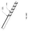
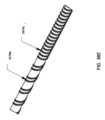
図2~図4は、いくつかの実施形態による、例示的なカテーテルシステム250の部分の概略図を提供する。カテーテルシステム250は、カテーテルシステム150と構造的かつ/又は機能的に同様であり得る。例えば、カテーテルシステム250は、制御ユニット(例えば、制御ユニット110)に結合され、かつ/又はアブレーション媒体供給部(例えば、アブレーション媒体供給部120)からアブレーション媒体を受容するように構成され得る。カテーテルシステム250は、外側シャフト260及び内側シャフト270を含み得る。内側シャフト270は第1のシャフトとも称され得、外側シャフト260は第2のシャフトと称され得る。いくつかの実施形態では、外側シャフト260及び内側シャフト270は、例えば、アブレーション処置を行うために一緒に使用される別個の構成要素であり得る。例えば、外側シャフト260は、アクセスシース又は導入器として実装することができ、内側シャフト270は、導入器の管腔内に挿入可能なカテーテルとして実装することができる。いくつかの実施形態では、外側シャフト260及び内側シャフト270は、単一カテーテルデバイス、例えば、2つの同心シャフトを有するデバイスに統合され得る。 2-4 provide schematic illustrations of portions of an
図2は、外側シャフト260の詳細図を提供する。外側シャフト260は、例えば、アクセスシースであり得る。外側シャフト260は、管腔262を画定することができる。管腔262は、例えば、内側シャフト270を含む、1つ以上の器具を受容するように構成され得る。外側シャフト260は、体内腔BL(例えば、胆嚢内腔)へのアクセスを提供するように構成され得る。例えば、外側シャフト260の遠位端は、図4に概略的に示されるように、体内腔BL内に位置決めされ得る。体内腔BLの内側に位置決めされると、外側シャフト260は、例えば、管腔262を介して、体内腔BL内への1つ以上の器具の送達を可能にすることができる。例えば、図4に示されるように、内側シャフト270は、外側シャフト260の管腔262内に挿入され、内側シャフト270の遠位端が体内腔BLの内側に位置決めされるように、体内腔BL内にナビゲートされ得る。 FIG. 2 provides a detailed view of outer shaft 260. Outer shaft 260 can be, for example, an access sheath. Outer shaft 260 can define a lumen 262. Lumen 262 may be configured to receive one or more instruments, including, for example, inner shaft 270. Outer shaft 260 may be configured to provide access to a body lumen BL (eg, the gallbladder lumen). For example, the distal end of outer shaft 260 may be positioned within body lumen BL, as schematically shown in FIG. 4. Once positioned inside the body lumen BL, the outer shaft 260 can enable delivery of one or more instruments into the body lumen BL, for example, via the lumen 262. For example, as shown in FIG. 4, the inner shaft 270 is inserted into the lumen 262 of the outer shaft 260 such that the distal end of the inner shaft 270 is positioned inside the body lumen BL. can be navigated within.
いくつかの実施形態では、管腔262は、流体(例えば、液体又はガス)及び/又はデブリ(例えば、胆石又はその断片、組織など)を体内腔BL内から排出又は排水するように構成され得る。例えば、管腔262は、体内腔BLに送達されたアブレーション媒体(例えば、低温アブレーション媒体)が体内腔BLから排出されることを可能にすることができる。いくつかの実施形態では、管腔262は、真空源240に動作可能に結合され得、真空源240は、流体を体内腔BL内から排出するために管腔262内に負圧を適用するように起動され得る。代替的に、管腔262は、流体が体内腔BLから出るための受動的排出通路として機能することができる。例えば、アブレーション媒体が体内腔BL内に送達され、圧力がシャフト260の外部に対して体内腔BL内で増加すると、そのような圧力は、管腔262を介して体内腔BLからアブレーション媒体の一部分を受動的に駆動することができる。 In some embodiments, lumen 262 may be configured to drain or drain fluid (e.g., liquid or gas) and/or debris (e.g., gallstones or fragments thereof, tissue, etc.) from within body lumen BL. . For example, lumen 262 can allow ablation media (eg, cryoablation media) delivered to body lumen BL to be drained from body lumen BL. In some embodiments, lumen 262 may be operably coupled to a vacuum source 240 that applies negative pressure within lumen 262 to evacuate fluid from within body lumen BL. can be activated. Alternatively, lumen 262 can function as a passive drainage passageway for fluid to exit body lumen BL. For example, when an ablation medium is delivered into the body lumen BL and pressure increases within the body lumen BL relative to the exterior of the shaft 260, such pressure causes a portion of the ablation medium to be removed from the body lumen BL via the lumen 262. can be driven passively.
いくつかの実施形態では、外側シャフト260は、1つ以上の追加の管腔、例えば、管腔264を画定することができ、これは、管腔262と構造的かつ/又は機能的に類似し得る。例えば、管腔264はまた、体内腔BL内へのアクセスを提供するように構成され得る。いくつかの実施形態では、管腔262は、内側シャフト270を受容するように構成され得、管腔264は、異なる手術及び/又は監視デバイス(例えば、プローブ、第2のアブレーションデバイスなど)を受容するように構成され得る。いくつかの実施形態では、管腔262、264のうちの1つ以上は、体内腔BL及び/又は身体の他の部分の圧力測定を可能にするように、センサ(例えば、圧力センサ)に流体的に結合され得る。例えば、制御ユニット(例えば、制御ユニット110)に統合されたセンサは、管腔262、264のうちの1つ以上と流体連通し、外側シャフト260及び/又は体内腔BL内の環境の測定(例えば、圧力測定)を行うことができる。 In some embodiments, outer shaft 260 can define one or more additional lumens, such as lumen 264, which is structurally and/or functionally similar to lumen 262. obtain. For example, lumen 264 may also be configured to provide access into body lumen BL. In some embodiments, lumen 262 may be configured to receive an inner shaft 270 and lumen 264 may be configured to receive a different surgical and/or monitoring device (e.g., a probe, a second ablation device, etc.). may be configured to do so. In some embodiments, one or more of the lumens 262, 264 provide fluid to a sensor (e.g., a pressure sensor) to enable pressure measurements in the body lumen BL and/or other parts of the body. can be combined as follows. For example, a sensor integrated into a control unit (e.g., control unit 110) may be in fluid communication with one or more of lumens 262, 264 to measure the environment within outer shaft 260 and/or body lumen BL, e.g. , pressure measurements).
いくつかの実施形態では、外側シャフト260は、センサ263を任意選択的に含む。いくつかの実施形態では、センサ263は、体内腔BL内に配設されるように構成されている外側シャフト260の遠位部分に位置し得る。代替的に、センサ263は、例えば、管腔(例えば、管腔262、264)内、外側シャフト260の近位端などを含む、外側シャフト260に沿った異なる場所に配設され得る。センサ263は、体内腔BL内の環境、又は外側シャフト260内及び/若しくは外側シャフト260を取り囲む他の環境に関する情報を捕捉するように構成され得る。例えば、センサは、体内腔BLに送達されているアブレーション媒体の特性(例えば、圧力、温度)、体内腔BLの特性(例えば、圧力、温度)、又は体内腔BL内の流体などを測定するように構成され得る。センサ263は、例えば、圧力センサ(例えば、圧力トランスデューサ、ひずみゲージトランスデューサ、ダイヤフラム変位センサ、光ファイバ圧力センサ、固体センサ)、温度センサ、光センサ、ガスセンサなどを含み得る。いくつかの実施形態では、センサ263は、例えば、外側シャフト260に結合され、かつ/又は外側シャフト260内に配設されたワイヤなどの有線接続を介して、制御ユニット(例えば、制御ユニット110)及び/又は他の計算デバイス(例えば、計算デバイス190)に結合され得る。いくつかの実施形態では、センサ263は、例えば、体内腔BLの1つ以上の測定された特性を示すデータを制御ユニット及び/又は別の計算デバイスに無線で伝送するように構成され得る。 In some embodiments, outer shaft 260 optionally includes a sensor 263. In some embodiments, sensor 263 may be located on a distal portion of outer shaft 260 that is configured to be disposed within body lumen BL. Alternatively, sensors 263 may be disposed at different locations along outer shaft 260, including, for example, within lumens (eg, lumens 262, 264), at the proximal end of outer shaft 260, and the like. Sensor 263 may be configured to capture information about the environment within body lumen BL or other environment within and/or surrounding outer shaft 260. For example, the sensor may be configured to measure a property of the ablation medium being delivered to the body lumen BL (e.g., pressure, temperature), a property of the body lumen BL (e.g., pressure, temperature), a fluid within the body lumen BL, etc. may be configured. Sensors 263 may include, for example, pressure sensors (eg, pressure transducers, strain gauge transducers, diaphragm displacement sensors, fiber optic pressure sensors, solid state sensors), temperature sensors, optical sensors, gas sensors, and the like. In some embodiments, sensor 263 is coupled to outer shaft 260 and/or via a wired connection, such as a wire disposed within outer shaft 260, to a control unit (e.g., control unit 110). and/or may be coupled to other computing devices (eg, computing device 190). In some embodiments, the sensor 263 may be configured to wirelessly transmit data indicative of one or more measured characteristics of the body lumen BL to a control unit and/or another computing device, for example.
いくつかの実施形態では、外側シャフト260は、外側シャフト260の遠位端にテーパ状部分又はテーパ状端を含み得る。いくつかの実施形態では、拡張器は、外側シャフト260の管腔(例えば、管腔262)内に挿入され、外側シャフト260の体内腔BL内への挿入を補助することができる。拡張器は、拡張器の遠位端が外側シャフト260から遠位に延在するように、管腔内に位置決めされ得る。そのような場合、外側シャフト260のテーパ状端は、BL内への挿入中にデバイスの外形に突然の段差を有するのではなく、体内腔BL内への挿入を補助する体内腔ために、外側シャフト260から拡張器の外面への円滑な移行を形成することができる。拡張器を外側シャフト260と共に使用することに関する更なる詳細は、図6A~図6Bを参照して提供される。 In some embodiments, outer shaft 260 may include a tapered portion or end at a distal end of outer shaft 260. In some embodiments, a dilator can be inserted into a lumen (eg, lumen 262) of outer shaft 260 to assist in inserting outer shaft 260 into body lumen BL. The dilator may be positioned within the lumen such that the distal end of the dilator extends distally from outer shaft 260. In such a case, the tapered end of the outer shaft 260 is designed to provide a smooth transition to the outer body lumen to aid insertion into the body lumen BL, rather than having an abrupt step in the profile of the device during insertion into the BL. A smooth transition from the shaft 260 to the outer surface of the dilator can be created. Further details regarding using the dilator with outer shaft 260 are provided with reference to FIGS. 6A-6B.
いくつかの実施形態では、外側シャフト260は、体内腔BL内で展開され得る、例えば、非展開状態又は構成から展開又は拡張状態又は構成に移行され得る、拡張可能な構造体又は本体266を含む。拡張可能な構造体266は、外側シャフト260と体内腔BLとの間の移動を防止し、かつ/又はシールを生成するように構成され得る。使用時、外側シャフト260は、外側シャフト260の遠位端が開口部を通して体内腔BL内に位置決めされるまで、例えば、ガイドワイヤに沿って前進することができる。次いで、拡張可能な構造体266は、図2において矢印290によって概略的に示されるように、展開(例えば、拡張、膨張)され得る。展開されると(例えば、展開状態になると)、拡張可能な構造体は、外側シャフト260が留置された開口部の直径よりも大きい直径を有し、したがって、外側シャフト260を体内腔BL内に保持するように構成され得る。いくつかの実施形態では、拡張可能な構造体266は、膨張可能バルーン、形状記憶構造体(例えば、展開可能ニチノール構造体)などを含む。いくつかの実施形態では、展開状態の拡張可能な構造体266は、外側シャフト260の外径よりも約1.5倍~約3倍大きい外径を有し得る。 In some embodiments, the outer shaft 260 includes an expandable structure or body 266 that can be deployed, e.g., transitioned from an undeployed state or configuration to a deployed or expanded state or configuration, within the body lumen BL. . Expandable structure 266 may be configured to prevent movement and/or create a seal between outer shaft 260 and body lumen BL. In use, outer shaft 260 can be advanced, eg, along a guidewire, until the distal end of outer shaft 260 is positioned through the opening and into body lumen BL. Expandable structure 266 may then be deployed (e.g., expanded, inflated), as illustrated schematically by
いくつかの実施形態では、拡張可能な構造体266は、外側シャフト260の一部分の圧縮及び/又は外側シャフトに対する内側シャフトの移動を介して、非展開状態から展開状態に移行することができる。例えば、拡張可能な構造体266は、2つの境界リングの間の外側シャフト260の長さに沿った領域内で境界付けられ得、拡張可能な構造体266は、2つの境界リングを互いに近づけると展開(例えば、拡張)することができる。いくつかの実施形態では、外側シャフト260は、複数の同心管又は管状部材から形成されているか、又はそれを含むことができ、例えば、内側管状部材を外側管状部材に対して並進させて、拡張可能な構造体266の端を互いに近づけて、拡張可能な構造体266を拡張する(例えば、拡張可能な構造体266を展開する)ことができる。そのような実施形態では、拡張可能な構造体266の少なくとも一端(例えば、近位端)は、外側管状部材に結合され得、拡張可能な構造体266の他端(例えば、遠位端)は、内側管状部材に結合され得、外側管状部材に対する内側管状部材の並進は、拡張可能な構造体266の拡張又は展開を引き起こすことができる。いくつかの実施形態では、拡張可能な構造体266は、その展開状態に拡張するように予め成形され得る。例えば、拡張可能な構造体266は、張力下で保持され(例えば、外側スリーブ若しくは管状部材によってその非展開状態で保持されるか、又は管状部材若しくはプルワイヤによって外側シャフト260の外面に沿って平坦に引き伸ばされ)、解放されると、その展開状態に自己拡張することができる。 In some embodiments, expandable structure 266 can transition from an undeployed state to a deployed state via compression of a portion of outer shaft 260 and/or movement of the inner shaft relative to the outer shaft. For example, expandable structure 266 may be bounded in a region along the length of outer shaft 260 between two bounding rings, and expandable structure 266 may be bounded in a region along the length of outer shaft 260 between two bounding rings; Can be expanded (e.g. expanded). In some embodiments, the outer shaft 260 can be formed from or include a plurality of concentric tubes or tubular members, e.g., by translating the inner tubular member relative to the outer tubular member to Expandable structure 266 can be expanded (eg, expandable structure 266 is deployed) by bringing the ends of expandable structure 266 closer together. In such embodiments, at least one end (e.g., the proximal end) of the expandable structure 266 can be coupled to the outer tubular member, and the other end (e.g., the distal end) of the expandable structure 266 can be coupled to the outer tubular member. , may be coupled to an inner tubular member, and translation of the inner tubular member relative to the outer tubular member may cause expansion or deployment of the expandable structure 266. In some embodiments, expandable structure 266 may be pre-shaped to expand to its deployed state. For example, expandable structure 266 may be held under tension (e.g., held in its undeployed state by an outer sleeve or tubular member, or stretched flat along the outer surface of outer shaft 260 by a tubular member or pull wire). When stretched) and released, it can self-expand to its expanded state.
いくつかの実施形態では、拡張可能な構造体266は、織られた又は編まれたパターンで配置された細長い部材(例えば、バンド、繊維、ワイヤ、スプライン)を含み得る。いくつかの実施形態では、細長い部材は、拡張可能な構造体266が非展開状態から展開状態に移行すると、球状形状を形成するように曲げられ得る。いくつかの実施形態では、細長い部材の一端を細長い部材の他端に対して直線的に圧縮することにより、拡張可能な構造体266を外向きに拡張させて、拡張した直径を有する幾何学形状を生成することができる。いくつかの実施形態では、拡張可能な構造体266は、非展開状態と比較して、展開状態でより大きい直径を有することができる。この拡張は、体内腔BLからの拡張可能な構造体266の意図しない除去を阻止するのを補助することができる。いくつかの実施形態では、拡張可能な構造体266は、ニチノール、ステンレス鋼、ポリマー、又は高張力緩和を有する任意の好適な材料から構成され得る。いくつかの実施形態では、拡張可能な構造体266は、例えば、形状記憶ニチノールなどの形状記憶材料から形成され得る。 In some embodiments, expandable structure 266 may include elongated members (eg, bands, fibers, wires, splines) arranged in a woven or knitted pattern. In some embodiments, the elongated member can bend to form a spherical shape when expandable structure 266 transitions from an undeployed state to a deployed state. In some embodiments, expandable structure 266 is expanded outwardly by linearly compressing one end of the elongate member against the other end of the elongate member to form a geometric shape having an expanded diameter. can be generated. In some embodiments, expandable structure 266 can have a larger diameter in the deployed state compared to the undeployed state. This expansion can help prevent unintentional removal of expandable structure 266 from body lumen BL. In some embodiments, expandable structure 266 may be constructed from Nitinol, stainless steel, polymer, or any suitable material with high strain relief. In some embodiments, expandable structure 266 may be formed from a shape memory material, such as shape memory nitinol, for example.
いくつかの実施形態では、拡張可能な構造体266は、アブレーションカテーテル250が配設されている開口部を封止するシールとして機能することができる。シールとして実装された好適な拡張可能な構造体266の更なる詳細は、参照により本明細書に組み込まれる国際出願第US2019/017112号に記載されている。 In some embodiments, expandable structure 266 can act as a seal to seal the opening in which
2つの管腔(例えば、管腔262、264)が図2に示されているが、外側シャフト260は、単一の管腔及び/又は3つ以上の管腔を含む、任意の数の管腔を含み得ることが理解され得る。外側シャフト260はまた、本明細書に記載の実施形態による、追加のセンサ、拡張可能な構造体などを含み得る。 Although two lumens (e.g., lumens 262, 264) are shown in FIG. 2, outer shaft 260 may include any number of lumens, including a single lumen and/or more than two lumens. It can be understood that it may include a cavity. Outer shaft 260 may also include additional sensors, expandable structures, etc. according to embodiments described herein.
図3は、管腔262内に配設された内側シャフト270のより詳細な図を提供する。内側シャフト270は、矢印291によって示されるように、軸方向の移動(例えば、外側シャフト260の長手方向軸に沿った並進)を介して、外側シャフト260及び管腔262から展開され得る。内側シャフト270は、例えば、アブレーション送達デバイス又はアブレーションカテーテルであり得る。いくつかの実施形態では、内側シャフト270は、冷凍アブレーションデバイスの一部分を形成し、低温アブレーション媒体を体内腔BL内に送達するように構成され得る。内側シャフト270は、体内腔BL内の細胞を死滅させることができるアブレーションエネルギー又はアブレーション媒体を提供するように構成され得る。例えば、内側シャフト270は、胆嚢内腔の粘膜層内の細胞を死滅させる、胆嚢管の内側を覆う細胞を死滅させる、又はこれらの任意の組み合わせを行うことができるアブレーションエネルギー又はアブレーション媒体を提供するように構成され得る。アブレーションエネルギー又は媒体は、例えば、化学薬剤(例えば、抗生物質、液体硬化剤、テトラデシル硫酸ナトリウム、酢酸、エタノール、高張塩化ナトリウム液、尿素)、低温アブレーション媒体(例えば、低温液体又はガス)、熱アブレーション、電気アブレーションなどを含み得る。いくつかの実施形態では、内側シャフト270は、複数のタイプのアブレーションエネルギー又は媒体を送達するように構成され得る。内側シャフト270は、空間的に拡散するアブレーションを提供するように構成され得る。別の言い方をすれば、内側シャフト270は、体内腔BLの大きな領域をアブレーションするアブレーションを提供するように構成され得る。いくつかの実施形態では、内側シャフト270は、胆嚢粘膜を非機能化するため、胆嚢管のアブレーション若しくは硬化のため、又はそれらの任意の組み合わせのためにアブレーションを送達するように構成され得る。 FIG. 3 provides a more detailed view of inner shaft 270 disposed within lumen 262. Inner shaft 270 may be deployed from outer shaft 260 and lumen 262 via axial movement (eg, translation along the longitudinal axis of outer shaft 260), as indicated by arrow 291. Inner shaft 270 can be, for example, an ablation delivery device or an ablation catheter. In some embodiments, the inner shaft 270 may form part of a cryoablation device and be configured to deliver cryoablation media into the body lumen BL. Inner shaft 270 may be configured to provide ablation energy or media that can kill cells within body lumen BL. For example, the inner shaft 270 provides ablation energy or ablation media that can kill cells within the mucosal layer of the gallbladder lumen, kill cells lining the cystic duct, or any combination thereof. It can be configured as follows. Ablation energy or media may include, for example, chemical agents (e.g., antibiotics, liquid sclerosing agents, sodium tetradecyl sulfate, acetic acid, ethanol, hypertonic sodium chloride solution, urea), cryogenic ablation media (e.g., cryogenic liquids or gases), thermal ablation , electrical ablation, and the like. In some embodiments, inner shaft 270 may be configured to deliver multiple types of ablation energy or media. Inner shaft 270 may be configured to provide spatially diffused ablation. Stated another way, the inner shaft 270 may be configured to provide ablation that ablates a large area of the body lumen BL. In some embodiments, the inner shaft 270 may be configured to deliver ablation to defunctionalize the gallbladder mucosa, for ablation or hardening of the cystic duct, or any combination thereof.
いくつかの実施形態では、内側シャフト270は、熱アブレーション、冷凍アブレーション、化学アブレーション、又はそれらの任意の組み合わせを送達するように構成され得る。いくつかの実施形態では、冷凍アブレーションは、液体窒素などの低温流体を胆嚢の壁に送達することを伴う。いくつかの実施形態では、冷凍アブレーションは、相変化に起因して低温を誘発する、亜酸化窒素又は二酸化炭素などのアブレーション媒体を胆嚢壁に送達することを伴う。いくつかの実施形態では、熱アブレーションは、例えば、温水又は蒸気などの高温流体を胆嚢の壁に送達することを含む。いくつかの実施形態では、アブレーティブ媒体は、液体形態、ガス形態、エアロゾル形態、ゲル形態、又はそれらの任意の組み合わせで送達される。 In some embodiments, inner shaft 270 may be configured to deliver thermal ablation, cryoablation, chemical ablation, or any combination thereof. In some embodiments, cryoablation involves delivering a cryogenic fluid, such as liquid nitrogen, to the wall of the gallbladder. In some embodiments, cryoablation involves delivering an ablation medium, such as nitrous oxide or carbon dioxide, to the gallbladder wall that induces low temperatures due to a phase change. In some embodiments, thermal ablation involves delivering a hot fluid, such as, for example, hot water or steam, to the wall of the gallbladder. In some embodiments, the ablative medium is delivered in liquid form, gas form, aerosol form, gel form, or any combination thereof.
内側シャフト270は、管腔272を画定することができる。管腔272は、例えば、アブレーション媒体供給部120から、体内腔BL内に配設可能なノズル274にアブレーション媒体を送達するように構成され得る。ノズル274は、アブレーション媒体を体内腔BL内に解放するように構成され得る。いくつかの実施形態では、ノズル274は、体内腔BL全体にアブレーション媒体を散布するための複数の開口部又は開窓を含み得る。いくつかの実施形態では、管腔272及びノズル274は、液体状態の低温アブレーション媒体を体内腔BL内に搬送するように構成され得る。管腔272及びノズル274は、アブレーション媒体がノズル274の開口部を出るまで、媒体が液体からガスへの転移を起こさないように、低温アブレーション媒体上に設定量の圧力を維持する寸法で構成され得る。別の言い方をすれば、管腔272及びノズル274は、液体状態の低温アブレーション媒体をノズル274の開口部に搬送するように構成され得、その時点で、体内腔BL内への低温アブレーション媒体の解放により、液体状態からガス状態への低温アブレーション媒体の変化をもたらす。いくつかの実施形態では、内側シャフト270の管腔272は、約0.001インチ~約0.1インチの直径を有し得、その間の全ての値及び部分範囲を含む。 Inner shaft 270 can define a lumen 272. Lumen 272 may be configured, for example, to deliver ablation media from ablation media supply 120 to nozzle 274 disposed within body lumen BL. Nozzle 274 may be configured to release ablation media into body lumen BL. In some embodiments, nozzle 274 may include multiple openings or fenestrations for dispersing ablation media throughout body lumen BL. In some embodiments, lumen 272 and nozzle 274 may be configured to deliver cryoablation media in liquid form into body lumen BL. The lumen 272 and nozzle 274 are dimensioned to maintain a set amount of pressure over the cryogenic ablation media such that the media does not undergo a liquid-to-gas transition until the ablation media exits the opening of the nozzle 274. obtain. Stated another way, lumen 272 and nozzle 274 may be configured to convey cryoablation medium in liquid state to the opening of nozzle 274, at which point the cryoablation medium is transferred into body lumen BL. The release results in a change of the cold ablation medium from a liquid state to a gas state. In some embodiments, the lumen 272 of the inner shaft 270 can have a diameter of about 0.001 inch to about 0.1 inch, including all values and subranges therebetween.
いくつかの実施形態では、内側シャフト270は、拡張可能な構造体又は本体276を含み得る。いくつかの実施形態では、拡張可能な構造体は、ノズル274の周りに配設され得る。いくつかの実施形態では、拡張可能な構造体276は、ノズル274が体内腔BL内の中心に置かれるように、体内腔BL内で拡張することができる。換言すれば、拡張可能な構造体276は、ノズル274の中心から体内腔BLの壁までの半径方向距離が、全ての半径方向において一貫しているか、又はほぼ一貫しているように、所望の直径まで外向きに拡張することができる。この一貫した間隔又はセンタリングは、ノズル274と体内腔BLの近くの組織との間の最小半径方向距離及び/又は体内腔BLを通るアブレーション媒体のより均一な散布を確実にすることができる。これは、内腔組織のアブレーションを可能にする一方で、アブレーション媒体が、組織のセクションからの範囲に近すぎない(例えば、固着又は穿孔リスクを生じる)、又は範囲から遠すぎない(例えば、アブレーションの有効性を低減する)ことを確実にすることができる。 In some embodiments, inner shaft 270 may include an expandable structure or body 276. In some embodiments, the expandable structure may be disposed around the nozzle 274. In some embodiments, expandable structure 276 can expand within body lumen BL such that nozzle 274 is centered within body lumen BL. In other words, the expandable structure 276 is configured such that the radial distance from the center of the nozzle 274 to the wall of the body lumen BL is consistent or nearly consistent in all radial directions. It can expand outward to a diameter. This consistent spacing or centering may ensure a minimum radial distance between the nozzle 274 and tissue near the body lumen BL and/or a more uniform distribution of the ablation medium through the body lumen BL. This allows ablation of luminal tissue while ensuring that the ablation medium is not too close to the area (e.g., creating a risk of sticking or perforation) or too far from the area (e.g., causing a risk of sticking or perforation). (reducing the effectiveness of
いくつかの実施形態では、拡張可能な構造体276の外形及び/又は熱質量は、ノズル274から体内腔BLの表面へのアブレーション媒体のより効率的な通過を可能にするように、最小限に抑えられ得る。換言すれば、拡張可能な構造体276が吸収又は放射することができる熱エネルギーの物理的サイズ及び量の両方を低減するか、又は最小限に抑えることで、アブレーション中の熱伝達の効率を改善することができる。いくつかの実施形態では、拡張可能な構造体276は、ニチノール、ステンレス鋼、ポリマー、又は高張力緩和を有する任意の好適な材料から構成され得る。いくつかの実施形態では、拡張可能な構造体276の材料は、カテーテルシステム250の冷却性能を著しく変更することなく低温に耐える材料の能力に基づいて選択することができる。いくつかの実施形態では、拡張可能な構造体276の使用は、冷凍アブレーションバルーンカテーテルとは対照的に、拡張可能な構造体276と体内腔BLとの間の有意な並置力の生成を回避することができる。これは、体内腔BLの内容物及び幾何学形状にあまり敏感でない、より効果的な冷却方法を生成することができる。 In some embodiments, the profile and/or thermal mass of expandable structure 276 is minimized to allow more efficient passage of ablation media from nozzle 274 to the surface of body lumen BL. It can be suppressed. In other words, reducing or minimizing both the physical size and amount of thermal energy that expandable structure 276 can absorb or radiate improves the efficiency of heat transfer during ablation. can do. In some embodiments, expandable structure 276 may be constructed from Nitinol, stainless steel, polymer, or any suitable material with high strain relief. In some embodiments, the material of expandable structure 276 can be selected based on the material's ability to withstand low temperatures without significantly altering the cooling performance of
いくつかの実施形態では、拡張可能な構造体276は、内側シャフト270が体内腔BLから除去され得るように、つぶれ可能又は後退可能であり得る。いくつかの実施形態では、拡張可能な構造体276は、ノズル274の外側の周りの体内腔BLの壁の等距離又はほぼ等距離の半径方向間隔を確実にするために、半径方向に対称であり得る。 In some embodiments, expandable structure 276 may be collapsible or retractable such that inner shaft 270 may be removed from body lumen BL. In some embodiments, the expandable structure 276 is radially symmetrical to ensure equidistant or near equidistant radial spacing of the walls of the body lumen BL around the exterior of the nozzle 274. could be.
いくつかの実施形態では、拡張可能な構造体276は、内側シャフト270の一部分の圧縮及び/又は内側シャフト270の別の部分に対する内側シャフト270の一部分の移動を介して、非拡張状態(例えば、非展開状態)から拡張状態(例えば、展開状態)に移行することができる。いくつかの実施形態では、拡張可能な構造体276は、織られた若しくは編まれたパターンで配置された、又は内側シャフト270の長さに沿って個々に配置された細長い部材(例えば、バンド、ワイヤ、繊維、スプライン)を含み得る。例えば、拡張可能な構造体276は、概して内側シャフト270の長さに沿って延在する1つ以上の細長い部材を含み得る。いくつかの実施形態では、拡張可能な構造体276は、単一の拡張可能な細長い部材を含み得るが、他の実施形態では、拡張可能な構造体は、2~20個(その間の全ての値及び部分範囲を含む)の細長い部材を含み得る。いくつかの実施形態では、拡張可能な構造体276の遠位端は、拡張可能な構造体276のより近位の点に向かって移動することができ、拡張可能な構造体276を拡張させる、すなわち、非展開状態又は構成から展開状態又は構成に移行させる。いくつかの実施形態では、内側シャフト270は、拡張可能な構造体276を拡張及び収縮させるように、スリーブ又は管状部材(図示せず)に対して移動することができる。例えば、スリーブは、拡張可能な構造体276を非展開状態に保持するために使用することができるか、又はスリーブは、拡張可能な構造体276の一端(例えば、近位端)を拡張可能な構造体276の他端(例えば、遠位端)に対して移動させて、拡張可能な構造体276をその拡張状態に拡張することができる。いくつかの実施形態では、拡張可能な構造体276は、ワイヤ又はバンドがアブレーションカテーテル250の近位端から前進及び後退することができるように、内側シャフト270の長さに沿って延在する複数のワイヤ又はバンドを含むことができる。そのような前進及び後退は、拡張可能な構造体276を展開及び展開解除するために使用され得る。拡張可能な構造体276の機構の更なる詳細は、例えば、図13A~図13C及び図32A~図32Cを含む、後の図を参照して説明される。 In some embodiments, the expandable structure 276 is brought into a non-expanded state (e.g., via compression of a portion of the inner shaft 270 and/or movement of a portion of the inner shaft 270 relative to another portion of the inner shaft 270). from a non-deployed state to an expanded state (e.g., a deployed state). In some embodiments, the expandable structures 276 include elongated members (e.g., bands, wires, fibers, splines). For example, expandable structure 276 may include one or more elongated members extending generally along the length of inner shaft 270. In some embodiments, the expandable structure 276 may include a single expandable elongate member, while in other embodiments, the expandable structure 276 may include between 2 and 20 expandable structures (everything in between). (including values and subranges). In some embodiments, the distal end of expandable structure 276 can be moved toward a more proximal point of expandable structure 276, causing expandable structure 276 to expand. That is, a transition is made from a non-deployed state or configuration to a deployed state or configuration. In some embodiments, inner shaft 270 can move relative to a sleeve or tubular member (not shown) to expand and contract expandable structure 276. For example, a sleeve can be used to hold expandable structure 276 in an undeployed state, or a sleeve can be used to hold one end (e.g., the proximal end) of expandable structure 276 in an expandable Movement relative to the other end (eg, distal end) of structure 276 can expand expandable structure 276 to its expanded state. In some embodiments, the expandable structure 276 has multiple expandable structures 276 extending along the length of the inner shaft 270 such that the wire or band can be advanced and retracted from the proximal end of the
いくつかの実施形態では、内側シャフト270は、任意選択的に、弁278を含み得る。弁278は、体内腔BL内へのアブレーション媒体の送達を制御するように構成され得る。例えば、弁278は、ノズル274へのアブレーション媒体の供給をオンにするか、又は遮断にするように構成され得る。いくつかの実施形態では、制御ユニット(例えば、制御ユニット110)は、弁278の開放及び/又は閉鎖を制御するように構成され得る。いくつかの実施形態では、(例えば、上述したように、ハンドヘルドデバイスに結合された)機械的アクチュエータが、弁278を開放及び/又は閉鎖するために使用され得る。いくつかの実施形態では、弁278は、体内腔BL内の圧力が所定の閾値よりも大きいことに応答して(例えば、自動的に、かつ/又は制御ユニットによる制御を介して)閉鎖するように構成され得る。いくつかの実施形態では、センサ(例えば、内側又は外側シャフト260、270上に配設されたセンサ、及び/又は制御ユニット110に結合されたセンサ)は、体内腔BL内の圧力を測定し、弁278を開放及び/又は閉鎖するように制御するために使用され得る。いくつかの実施形態では、弁278は、体内腔BLと排出管腔(例えば、管腔262)との間の圧力差に応答して閉鎖するように構成され得、例えば、遮断物又は閉塞物が排出経路に沿って形成されたことを示す。例えば、複数のセンサは、カテーテルシステム250及び/又は体内腔BLに関連付けられた異なる圧力を測定するように構成され得、制御ユニット(例えば、制御ユニット110)は、予期せぬ障害物が体内腔BL内への、かつ/又は外への任意の流体流路を隔離したときをそのような圧力測定値がいつ判定するかを分析するように構成され得る。 In some embodiments, inner shaft 270 may optionally include a valve 278. Valve 278 may be configured to control delivery of ablation media into body lumen BL. For example, valve 278 may be configured to turn on or shut off the supply of ablation medium to nozzle 274. In some embodiments, a control unit (eg, control unit 110) may be configured to control the opening and/or closing of valve 278. In some embodiments, a mechanical actuator (e.g., coupled to a handheld device, as described above) may be used to open and/or close valve 278. In some embodiments, the valve 278 is configured to close (e.g., automatically and/or via control by a control unit) in response to the pressure within the body lumen BL being greater than a predetermined threshold. may be configured. In some embodiments, a sensor (e.g., a sensor disposed on the inner or outer shaft 260, 270 and/or a sensor coupled to the control unit 110) measures pressure within the body lumen BL; It can be used to control valve 278 to open and/or close. In some embodiments, the valve 278 may be configured to close in response to a pressure difference between the body lumen BL and the drainage lumen (e.g., lumen 262), e.g., a blocker or occlusion. indicates that it was formed along the ejection path. For example, the plurality of sensors may be configured to measure different pressures associated with the
上述したように、いくつかの実施形態では、内側シャフト270は、冷凍アブレーションデバイスであるか、又はその一部を形成し、低温アブレーション媒体を体内腔BL内に送達するように構成され得る。冷凍アブレーションデバイスは、特定の冷凍アブレーション媒体(例えば、液体亜酸化窒素)の相変化特性を活用して、標的組織界面において冷凍アブレーション温度を誘発することができる。このような低温アブレーション媒体は、液体からガスに転移するとき、体積が膨張し、体内腔BL内の圧力の増加を引き起こすことができる。したがって、本明細書に開示されるシステム及びデバイスを設計する際の1つの重要な考慮事項は、アブレーション処置中の体内腔BL内の腔内圧の監視及び制御にある。例えば、本明細書に開示されるシステム及びデバイスは、腔内圧が、所定の閾値を上回って増加せず、かつ/又は所定の範囲内にあることを確実にするように構成され得る。腔内圧の増加(例えば、所定の閾値を上回る圧力、又は所定の率を上回る圧力の突然の変化)がある場合、本明細書に開示されるシステム及びデバイスは、空気、ガス状冷凍アブレーション媒体、及び/又は他の流体を体内腔BL内から排出し、腔内圧を低減させるように構成され得る。そのような場合、カテーテルシステム250内(例えば、内側シャフト270の管腔272内)及び/又はカテーテルシステム250内への供給ラインの任意の低温アブレーション媒体が、カテーテルシステム250(例えば、ノズル274)から体内腔BL内に出ないことを確実にすることが重要であり得、圧力増加に更に加わる。したがって、圧力増加事象(例えば、所定の閾値を上回る圧力、又は所定の率体内腔を上回る圧力の突然の変化)の検出に応答して、BL内に送達される残留低温アブレーション媒体の量を最小限に抑えるか、又は低減することが望ましい場合がある。いくつかの実施形態では、弁278を使用して、体内腔270内に送達される残留低温アブレーション媒体の量を低減することができる。弁278は、弁278が、閉鎖時に、管腔272及び/又はノズル274につながる他の通路内の任意の残留又は過剰アブレーション媒体が体内腔BL内に送達されることを防止するように、ノズル274に又はその近くに位置決めされ得る。 As mentioned above, in some embodiments, the inner shaft 270 is or forms part of a cryoablation device and may be configured to deliver cryoablation media into the body lumen BL. Cryoablation devices can exploit the phase change properties of certain cryoablation media (eg, liquid nitrous oxide) to induce cryoablation temperatures at target tissue interfaces. When such a cryoablation medium transitions from liquid to gas, it expands in volume and can cause an increase in pressure within the body lumen BL. Therefore, one important consideration in designing the systems and devices disclosed herein is the monitoring and control of intraluminal pressure within the body lumen BL during the ablation procedure. For example, the systems and devices disclosed herein can be configured to ensure that intraluminal pressure does not increase above a predetermined threshold and/or is within a predetermined range. When there is an increase in intraluminal pressure (e.g., a pressure above a predetermined threshold, or a sudden change in pressure above a predetermined rate), the systems and devices disclosed herein can be used to reduce air, gaseous cryoablation media, and/or other fluids from within the body lumen BL to reduce intraluminal pressure. In such a case, any cryogenic ablation media within catheter system 250 (e.g., within lumen 272 of inner shaft 270) and/or in the supply line into
弁278は、任意の範囲の好適な機構を含み得る。いくつかの実施形態では、弁は、その静止状態で閉鎖され得るが、アブレーション媒体が体内腔BL内に送達されることを可能にするように開放され得る。代替的に、弁278は、その静止状態で開放され得、追加のアブレーション媒体が体内腔BL内に送達されることを防止するように閉鎖され得る。いくつかの実施形態では、弁278は、ばね機構を使用して、閉鎖され、かつ/又は開放されるように付勢され得る。弁278は、例えば、立方体、円錐、円筒、三角柱、トーラス、螺旋、卵形、又はアブレーション媒体流を妨げるのに十分な構造を有する他の三次元体を含む、任意の好適な幾何学形状を有することができる。いくつかの実施形態では、弁278は、内側シャフト270内(例えば、管腔272内)に画定された弁座に対して着座され得る。いくつかの実施形態では、弁278は、手動で、又は制御デバイス(例えば、制御デバイス110)を介して、駆動ワイヤ若しくはロッド、空気圧若しくは油圧、電磁力、及び/又はモータを用いて作動されて、開放及び/又は閉鎖することができる。好適な弁の例は、参照により本明細書に組み込まれる国際出願第US2020/045436号に記載されている。 Valve 278 may include any range of suitable features. In some embodiments, the valve may be closed in its resting state, but opened to allow ablation media to be delivered into the body lumen BL. Alternatively, valve 278 may be open in its resting state and may be closed to prevent additional ablation media from being delivered into body lumen BL. In some embodiments, valve 278 may be biased closed and/or open using a spring mechanism. Valve 278 can have any suitable geometric shape, including, for example, a cube, cone, cylinder, prism, torus, spiral, oval, or other three-dimensional body with sufficient structure to obstruct ablation media flow. can have In some embodiments, valve 278 may be seated against a valve seat defined within inner shaft 270 (eg, within lumen 272). In some embodiments, the valve 278 is actuated using a drive wire or rod, pneumatic or hydraulic, electromagnetic force, and/or a motor, either manually or via a control device (e.g., control device 110). , can be open and/or closed. Examples of suitable valves are described in International Application No. US2020/045436, which is incorporated herein by reference.
いくつかの実施形態では、内側シャフト270は、センサ273を任意選択的に含む。いくつかの実施形態では、センサ273は、体内腔BL内に配設されるように構成されている内側シャフト270の遠位部分に位置し得る。代替的に、センサ273は、例えば、管腔(例えば、管腔272)内、内側シャフト270の近位端などを含む、内側シャフト270に沿った異なる場所に配設され得る。センサ273は、体内腔BL内の環境に関する情報を捕捉するように構成され得る。例えば、センサ273は、体内腔BLに送達されているアブレーション媒体の特性(例えば、圧力、温度)、体内腔BLの特性(例えば、圧力、温度)、又は体内腔BL内の流体などを測定するように構成され得る。センサ273は、例えば、圧力センサ(例えば、圧力トランスデューサ、ひずみゲージトランスデューサ、ダイヤフラム変位センサ、光ファイバ圧力センサ、固体センサ)、温度センサ、光センサ、ガスセンサなどを含み得る。センサ273は、有線又は無線接続を介して、制御ユニット(例えば、制御ユニット110)及び/又は他の計算デバイス(例えば、計算デバイス190)にデータ(例えば、センサ測定値)を通信することが可能であり得る。 In some embodiments, inner shaft 270 optionally includes a sensor 273. In some embodiments, sensor 273 may be located on a distal portion of inner shaft 270 that is configured to be disposed within body lumen BL. Alternatively, sensor 273 may be disposed at different locations along inner shaft 270, including, for example, within a lumen (eg, lumen 272), at the proximal end of inner shaft 270, and the like. Sensor 273 may be configured to capture information regarding the environment within body lumen BL. For example, the sensor 273 measures a property of the ablation medium being delivered to the body lumen BL (e.g., pressure, temperature), a property of the body lumen BL (e.g., pressure, temperature), a fluid within the body lumen BL, etc. It can be configured as follows. Sensors 273 may include, for example, pressure sensors (eg, pressure transducers, strain gauge transducers, diaphragm displacement sensors, fiber optic pressure sensors, solid state sensors), temperature sensors, optical sensors, gas sensors, and the like. Sensor 273 can communicate data (e.g., sensor measurements) to a control unit (e.g., control unit 110) and/or other computing device (e.g., computing device 190) via a wired or wireless connection. It can be.
いくつかの実施形態では、内側シャフト270は、任意選択的に、1つ以上の追加の管腔を含み得る。いくつかの実施形態では、管腔は、体内腔BL及び/又はカテーテルシステム250の他の部分から圧力情報又は他の条件(例えば、温度)を中継するための通路として構成され得る。いくつかの実施形態では、カテーテルシステム250は、図22を参照して更に説明されるように、任意選択的に、閉塞器を含み得る。単一の管腔(例えば、管腔272)が図3に示されているが、内側シャフト270は、単一の管腔及び/又は3つ以上の管腔を含む、任意の数の管腔を含み得ることが理解され得る。内側シャフト270はまた、本明細書に記載の実施形態による、追加のセンサ、弁、ノズルなどを含み得る。 In some embodiments, inner shaft 270 may optionally include one or more additional lumens. In some embodiments, the lumen may be configured as a passageway for relaying pressure information or other conditions (eg, temperature) from the body lumen BL and/or other portions of the
図4は、体内腔BL内に位置決めされた内側シャフト270及び外側シャフト260の詳細図を提供する。内側シャフト270は、外側シャフト260の管腔262内に配設することができる。内側シャフト270の外面と管腔262の内面との間の間隔は、体内腔BLからガス及び/又は他の流体(例えば、体内腔BLからのアブレーション媒体)を除去するための排出管腔又は通路を画定することができる。 FIG. 4 provides a detailed view of the inner shaft 270 and outer shaft 260 positioned within the body lumen BL. Inner shaft 270 may be disposed within lumen 262 of outer shaft 260. The spacing between the outer surface of inner shaft 270 and the inner surface of lumen 262 provides a drainage lumen or passageway for removing gas and/or other fluids (e.g., ablation media from body lumen BL) from body lumen BL. can be defined.
外側シャフト260及び/又は内側シャフト270は、可撓性及び/又は半可撓性の材料で形成することができ、これにより、例えば、ガイドワイヤに沿って、各々を体内腔BLにナビゲートすることができる。材料は、医療グレードの生体適合性材料であり得る。内側シャフト270は、矢印294によって示される軸方向で体内腔BL内に展開され得る。外側シャフト260の拡張可能な構造体266及び内側シャフト270の拡張可能な構造体276は、矢印292によって示されるように、半径方向に展開され得る。 The outer shaft 260 and/or the inner shaft 270 can be formed of flexible and/or semi-flexible materials, thereby allowing each to be navigated into the body lumen BL, e.g., along a guidewire. be able to. The material can be a medical grade biocompatible material. Inner shaft 270 may be deployed within body lumen BL in an axial direction indicated by
図5は、いくつかの実施形態による、例示的な制御ユニット310の概略図である。制御ユニット310は、図1を参照して説明されるように、制御ユニット110と構造的かつ/又は機能的に同様であり得る。例えば、制御ユニット310は、アブレーションシステム及び/又はカテーテルシステム(例えば、アブレーションシステム100、カテーテルシステム250)の1つ以上の構成要素を制御するように構成され得る。制御ユニット310は、プロセッサ312、メモリ314、及び入力/出力インターフェース319を含み得る。いくつかの実施形態では、制御ユニット310は、例えば、カテーテルシステムの近位端に結合されているハンドヘルドデバイス内に含まれることによって、カテーテルシステムに結合され得る。いくつかの実施形態では、制御ユニット310は、例えば、遠隔コンピュータデバイス又はシステム上に遠隔に位置することができ、カテーテルシステムの動作を遠隔制御するために使用され得る。 FIG. 5 is a schematic diagram of an example control unit 310, according to some embodiments. Control unit 310 may be structurally and/or functionally similar to control unit 110, as described with reference to FIG. For example, control unit 310 may be configured to control one or more components of an ablation system and/or catheter system (eg, ablation system 100, catheter system 250). Control unit 310 may include a processor 312, memory 314, and input/output interface 319. In some embodiments, control unit 310 may be coupled to the catheter system, for example, by being included within a handheld device coupled to the proximal end of the catheter system. In some embodiments, control unit 310 can be remotely located, for example, on a remote computer device or system, and can be used to remotely control operation of the catheter system.
制御ユニット310のプロセッサ312は、カテーテルシステムの1つ以上の構成要素を展開すること(例えば、シャフトを前進させるか、又は後退させること、拡張可能な構造体を展開すること、弁を開放及び/又は閉鎖すること)、アブレーション媒体を体内腔内に送達すること、カテーテルシステムを伴うアブレーション処置に関連付けられたセンサデータを分析すること、体内腔内の温度及び/又は圧力を制御することなどに関連付けられた機能を稼働及び/又は実行するように構成された任意の好適な処理デバイスであり得る。プロセッサ312は、モジュール、機能、及び/又はプロセスを実行するように構成され得る。プロセッサ312は、汎用プロセッサ、フィールドプログラマブルゲートアレイ(Field Programmable Gate Array、FPGA)、特定用途向け集積回路(Application Specific Integrated Circuit、ASIC)、デジタル信号プロセッサ(Digital Signal Processor、DSP)などであり得る。いくつかの実施形態では、プロセッサ312は、例えば、集積回路などの回路の一部である。いくつかの実施形態では、例えば、1つ以上のセンサを含む、アブレーションシステムの1つ以上の他の構成要素が、回路に統合され得る。 The processor 312 of the control unit 310 is responsible for deploying one or more components of the catheter system (e.g., advancing or retracting a shaft, deploying an expandable structure, opening a valve, and/or or closing), delivering an ablation medium into a body lumen, analyzing sensor data associated with an ablation procedure involving a catheter system, controlling temperature and/or pressure within a body lumen, etc. The processing device may be any suitable processing device configured to operate and/or perform the functions provided. Processor 312 may be configured to execute modules, functions, and/or processes. Processor 312 may be a general purpose processor, a field programmable gate array (FPGA), an application specific integrated circuit (ASIC), a digital signal processor (DSP), or the like. In some embodiments, processor 312 is part of a circuit, such as an integrated circuit, for example. In some embodiments, one or more other components of the ablation system may be integrated into the circuit, including, for example, one or more sensors.
入力/出力インターフェース319は、制御ユニット310を1つ以上の外部計算デバイスに接続するためのユーザインターフェース及び/又は通信インターフェースを含み得る。ユーザインターフェースは、入力を受信し、他のデバイス及び/又はデバイスを動作させるユーザ、例えば、カテーテルシステムを動作させるユーザに出力を送信するように構成されている、1つ以上の構成要素を含み得る。例えば、ユーザインターフェースは、ディスプレイデバイス(例えば、ディスプレイ、タッチスクリーンなど)、オーディオデバイス(例えば、スピーカ又はアラーム)、及び入力を受信し、かつ/又はユーザへの出力を生成するように構成された1つ以上の追加の入力/出力デバイスを含み得る。通信インターフェースは、例えば、1つ以上のネットワーク(例えば、ローカルエリアネットワーク(local area network、LAN)、広域ネットワーク(wide area network、WAN)、仮想ネットワーク、電気通信ネットワーク)を介して他の計算デバイス(例えば、計算デバイス190)と通信するための、1つ以上の無線及び/又は有線インターフェースを含み得る。 Input/output interface 319 may include a user interface and/or a communications interface for connecting control unit 310 to one or more external computing devices. The user interface may include one or more components configured to receive input and send output to other devices and/or users operating devices, e.g., users operating catheter systems. . For example, a user interface may include a display device (e.g., a display, a touch screen, etc.), an audio device (e.g., a speaker or an alarm), and a device configured to receive input and/or generate output to a user. It may include one or more additional input/output devices. The communication interface may, for example, connect the other computing device ( For example, the computing device 190 may include one or more wireless and/or wired interfaces for communicating with the computing device 190).
メモリ314は、例えば、ランダムアクセスメモリ(random access memory、RAM)、メモリバッファ、ハードドライブ、データベース、消去可能プログラマブル読み出し専用メモリ(erasable programmable read-only memory、EPROM)、電気的消去可能読み出し専用メモリ(electrically erasable read-only memory、EEPROM)、読み出し専用メモリ(read-only memory、ROM)などであり得る。いくつかの実施形態では、メモリ314は、プロセッサ312に、カテーテルシステムの1つ以上の構成要素を展開すること(例えば、シャフトを前進又は後退させること、拡張可能な構造体を展開すること、弁を開放及び/又は閉鎖すること)、アブレーション媒体を体内腔内に送達すること、カテーテルシステムを伴うアブレーション処置に関連付けられたセンサデータを分析すること、体内腔内の温度及び/又は圧力を制御することなどに関連付けられたモジュール、プロセス、及び/又は機能を実行させる命令を記憶する。本明細書で説明される方法は、例えば、メモリ314、又は制御ユニット310に動作可能に結合されたメモリなどの制御ユニット310の電子記憶場所に記憶された機械(例えば、コンピュータプロセッサ)実行可能コードによって実装され得る。いくつかの実施形態では、機械実行可能コード又は機械可読コードは、ソフトウェアの形態で提供される。動作において、コードは、プロセッサ312によって実行され得る。場合によっては、コードは、プロセッサ312によってアクセス及び/又は実行されるためにメモリ314から取り出される。 Memory 314 can include, for example, random access memory (RAM), memory buffers, hard drives, databases, erasable programmable read-only memory (EPROM), electrically erasable programmable read-only memory (EPROM), and electrically erasable programmable read-only memory (EPROM). It may be electrically erasable read-only memory (EEPROM), read-only memory (ROM), etc. In some embodiments, memory 314 directs processor 312 to deploy one or more components of the catheter system (e.g., advance or retract a shaft, deploy an expandable structure, deploy a valve, etc.). opening and/or closing a body lumen), delivering an ablation medium into a body lumen, analyzing sensor data associated with an ablation procedure involving a catheter system, controlling temperature and/or pressure within a body lumen. Stores instructions for executing modules, processes, and/or functions associated with, etc. The methods described herein may be performed using machine (e.g., computer processor) executable code stored in an electronic storage location of control unit 310, such as, for example, memory 314 or a memory operably coupled to control unit 310. can be implemented by In some embodiments, machine-executable or machine-readable code is provided in the form of software. In operation, the code may be executed by processor 312. In some cases, code is retrieved from memory 314 for access and/or execution by processor 312.
図5に示すように、メモリ314は、プロセッサ312に、排出制御部315、アブレーション媒体供給制御部316、任意選択的に、センサ制御部317、及び/又は任意選択的に、ノズル制御部318として示されるモジュール、プロセス、及び/又は機能を実行させることができる命令を記憶する。排出制御部315、アブレーション媒体供給制御部316、センサ制御部317、及び/又はノズル制御部318は、ハードウェア構成要素に結び付けられている1つ以上のプログラム及び/又はアプリケーションとして実装され得る。例えば、排出制御部315、アブレーション媒体供給制御部316、センサ制御部317、及び/又はノズル制御部318は、アブレーションシステム及び/又はカテーテルシステム(例えば、アブレーションシステム100、カテーテルシステム250)の1つ以上の構成要素によって実装され得る。いくつかの実施形態では、排出制御部315を実行するプロセッサ312は、弁の開放及び/又は真空源の作動を制御して、ガス又は他の流体(例えば、アブレーション媒体)を体内腔から排出することができる。いくつかの実施形態では、アブレーション媒体供給制御部316を実行するプロセッサ312は、カテーテルシステムを介して体内腔内にアブレーション媒体を送達するように、弁の開放及び/又はアブレーション供給源の動作を制御することができる。いくつかの実施形態では、センサ制御部317を実行するプロセッサ312は、1つ以上のセンサからのデータを受信、処理、及び/若しくは分析し、かつ/又はそのようなデータを使用して、アブレーションシステム若しくはカテーテルシステムの1つ以上の他の構成要素の動作を制御することができる。 As shown in FIG. 5, the memory 314 provides the processor 312 with an ejection control 315, an ablation media supply control 316, optionally a sensor control 317, and/or an optional nozzle control 318. Store instructions that can cause the indicated module, process, and/or function to be executed. Ejection control 315, ablation media supply control 316, sensor control 317, and/or nozzle control 318 may be implemented as one or more programs and/or applications tied to hardware components. For example, the evacuation control 315, the ablation media supply control 316, the sensor control 317, and/or the nozzle control 318 may be connected to one or more of the ablation systems and/or catheter systems (e.g., ablation system 100, catheter system 250). can be implemented by components of In some embodiments, the processor 312 executing the evacuation control 315 controls the opening of valves and/or activation of the vacuum source to eject gas or other fluid (e.g., ablation media) from the body lumen. be able to. In some embodiments, the processor 312 executing the ablation media supply controller 316 controls the opening of the valve and/or the operation of the ablation source to deliver the ablation media into the body lumen via the catheter system. can do. In some embodiments, processor 312 executing sensor controller 317 receives, processes, and/or analyzes data from one or more sensors and/or uses such data to perform ablation. Operation of one or more other components of the system or catheter system can be controlled.
いくつかの実施形態では、ノズル制御部318は、体内腔(例えば、体内腔BL)内の1つ以上のノズル(例えば、ノズル274)の位置決め又は移動を制御するように実装され得る。いくつかの実施形態では、ノズル制御部318は、アブレーションカテーテル(例えば、内側シャフト270)をその中心軸に沿って回転させて、液体寒剤媒体の均一な又はより分散した送達を増加させるように実装され得る。いくつかの実施形態では、ノズル制御部318は、アブレーションカテーテル及び/又はノズルを作動させて、軸方向又は直線的に移動させ、ノズルからの寒剤の散布を増加させることができる。いくつかの実施形態では、ノズル制御部318は、1つ以上のノズル開口部を開閉するように実装され得る。 In some embodiments, nozzle control 318 may be implemented to control the positioning or movement of one or more nozzles (eg, nozzle 274) within a body lumen (eg, body lumen BL). In some embodiments, nozzle control 318 is implemented to rotate the ablation catheter (e.g., inner shaft 270) along its central axis to increase uniform or more dispersed delivery of the liquid cryogen medium. can be done. In some embodiments, the nozzle control 318 can actuate the ablation catheter and/or the nozzle to move it axially or linearly to increase the distribution of cryogen from the nozzle. In some embodiments, nozzle control 318 may be implemented to open or close one or more nozzle openings.
図6A~図6Bは、実施形態による、アブレーション処置中のアブレーション並びに圧力及び/又は温度の管理のための例示的な方法600を示す。いくつかの実施形態では、アブレーション処置は、冷凍アブレーションデバイスを含むアブレーションシステム(例えば、アブレーションシステム100)を使用して実装される冷凍アブレーション処置であり得る。いくつかの実施形態では、アブレーション処置は、胆嚢を非機能化するために胆嚢内で行われる。方法600は、任意選択的に、602で、アブレーションシステムのカテーテルシステム(例えば、カテーテルシステム150、250)の外側シャフト(例えば、外側シャフト260)を体内腔(例えば、胆嚢内腔)内に前進させることを含む。いくつかの実施形態では、超音波撮像が、体内腔を可視化するために使用され得る。いくつかの実施形態では、標準的な針及びガイドワイヤが、経肝アプローチを介して、例えば、セルディンガー法を使用して、体内腔にアクセスするために使用され得る。標的体内腔が胆嚢であるとき、針を通る胆汁の視覚的戻り、及び体内腔の内側でのガイドワイヤカールの蛍光透視確認は、体内腔内のガイドワイヤの適切な留置を検証することを支援することができる。いくつかの実施形態では、外側シャフトは、拡張器が外側シャフトの管腔(例えば、管腔262)内に位置決めされた状態で、ガイドワイヤに沿って前進することができる。いくつかの実施形態では、一連の徐々に大きくなる拡張器は、ガイドワイヤに沿って前進し、体内腔内に管を拡張することができる。管を拡張した後、(例えば、その中に拡張器が挿入された)外側シャフトは、ガイドワイヤに沿って体内腔内に前進することができる。いくつかの実施形態では、カテーテルシステムの外側シャフトは、内側シャフトを体内腔内に留置する前に、まず体内腔内に留置される別個の管状構造体、例えば、アクセスシース又は導入器であり得る。代替的に、いくつかの実施形態では、外側及び内側シャフトは、体内腔内に同時に留置され得る。いくつかの実施形態では、外側シャフトの留置は、経皮ドレナージ管留置法と同様であり得る。外側シャフトが体内腔内に位置決めされると、拡張器及びガイドワイヤは、以下に更に説明されるように、外側シャフト内の内側シャフトの留置を可能にするために除去され得る。 6A-6B illustrate an example method 600 for ablation and pressure and/or temperature management during an ablation procedure, according to an embodiment. In some embodiments, the ablation procedure may be a cryoablation procedure implemented using an ablation system (eg, ablation system 100) that includes a cryoablation device. In some embodiments, the ablation procedure is performed within the gallbladder to render it non-functional. The method 600 optionally includes, at 602, advancing an outer shaft (e.g., outer shaft 260) of a catheter system (e.g., catheter system 150, 250) of an ablation system into a body lumen (e.g., gallbladder lumen). Including. In some embodiments, ultrasound imaging may be used to visualize body lumens. In some embodiments, standard needles and guidewires may be used to access body lumens via a transhepatic approach, such as using the Seldinger technique. When the target body lumen is the gallbladder, visual return of bile through the needle and fluoroscopic confirmation of the guidewire curl inside the body lumen helps to verify proper placement of the guidewire within the body lumen. can do. In some embodiments, the outer shaft can be advanced along the guidewire with the dilator positioned within the outer shaft lumen (eg, lumen 262). In some embodiments, a series of progressively larger dilators can be advanced along the guidewire to expand the tube into the body lumen. After dilating the tube, the outer shaft (eg, with a dilator inserted therein) can be advanced into the body lumen along the guidewire. In some embodiments, the outer shaft of the catheter system can be a separate tubular structure, such as an access sheath or an introducer, that is first placed within the body lumen before the inner shaft is placed within the body lumen. . Alternatively, in some embodiments, the outer and inner shafts may be placed within the body lumen simultaneously. In some embodiments, placement of the outer shaft can be similar to percutaneous drainage tube placement. Once the outer shaft is positioned within the body lumen, the dilator and guidewire may be removed to allow placement of the inner shaft within the outer shaft, as described further below.
いくつかの実施形態では、カテーテルシステムは、胆嚢内腔内に留置することができる。カテーテルシステムによる胆嚢へのアクセスは、経皮的アプローチによって達成することができる。いくつかの実施形態では、カテーテルシステムのアクセスシース又は外側シャフト760は、図7Aに見られるように、超音波誘導を使用して、経肝経皮アプローチを通して胆嚢2にアクセスする。いくつかの実施形態では、カテーテルデバイスのアクセスシース760は、図7Bに見られるように、超音波誘導を使用して、肝下経皮アプローチを通して胆嚢2にアクセスする。いくつかの実施形態では、経皮的アプローチは、胆嚢フィステル形成ドレーンを留置するために使用される方法と同様である。いくつかの実施形態では、本明細書で提供されるアクセスシース760は、図7Cに示されるように、胆嚢2に内視鏡的にアクセスする。いくつかの実施形態では、アクセスシース760は、図7Cに示されるように、胆嚢の内腔を小腸の管腔に接続する経壁ストーマを作成することによって、生来の生体構造を利用して、胆嚢2にアクセスする。いくつかの実施形態では、経皮的アクセスは、中空ボア針を使用して得られ、それによって、ガイドワイヤが、針を通して留置され、所望のアクセス場所(例えば、胆嚢管、胆嚢、又はそれらの組み合わせ)への管を生成する。いくつかの実施形態では、アクセスシース760及び内側シャフト又はアブレーションカテーテルは、ガイドワイヤが通過することを可能にするように、同心管腔で構成されている。いくつかの実施形態では、アクセスシース760及びアブレーションカテーテルは、ガイドワイヤが通過することを可能にするように、非同心管腔で構成されている。 In some embodiments, the catheter system can be placed within the gallbladder lumen. Access to the gallbladder with a catheter system can be achieved by a percutaneous approach. In some embodiments, the access sheath or
カテーテルシステムの外側シャフトの遠位端を体内腔内に位置決めした後、方法600は、任意選択的に、604で、外側シャフトの拡張可能な構造体(例えば、拡張可能な構造体266)を展開することを含み得る。拡張可能な構造体を体内腔内で展開することは、外側シャフト(例えば、アクセスカテーテル、導入器)が、アブレーション処置の間、体内腔内に留まるか、又は保持されることを確実にすることができる。いくつかの実施形態では、拡張可能な構造体を展開することは、第1の管状部材を第2の管状部材に対して移動させて、拡張可能な構造体の第1の端を拡張可能な構造体の第2の端に向かって移動させ、それによって拡張可能な構造体を外向きに拡張させることを伴い得る。いくつかの実施形態では、拡張可能な構造体を拡張することは、(例えば、シース又はプルワイヤを解放することによって)拡張可能な部材にかけられた張力を解放すること、並びに拡張可能な構造体が予め形成された形状に自動的に拡張又は自己拡張することを可能にすることを伴い得る。 After positioning the distal end of the outer shaft of the catheter system within the body lumen, method 600 optionally includes deploying an expandable structure (e.g., expandable structure 266) of the outer shaft at 604. may include doing. Deploying the expandable structure within the body lumen ensures that the outer shaft (e.g., access catheter, introducer) remains or is retained within the body lumen during the ablation procedure. I can do it. In some embodiments, deploying the expandable structure includes moving the first tubular member relative to the second tubular member to cause the first end of the expandable structure to It may involve moving toward the second end of the structure, thereby expanding the expandable structure outwardly. In some embodiments, expanding the expandable structure includes releasing tension on the expandable member (e.g., by releasing a sheath or pull wire) and It may involve allowing automatic expansion or self-expansion into a pre-formed shape.
方法600は、606で、カテーテルシステムの内側シャフト(例えば、内側シャフト270)を体内腔内に前進させることを含み得る。いくつかの実施形態では、拡張器が外側シャフト内に位置決めされ、外側シャフトを体内腔内に前進させた場合、内側シャフトは、拡張器の除去後に前進することができる。内側シャフトは、内側シャフトのノズル(例えば、ノズル274)が外側シャフトの遠位端に対して遠位の体内腔内に配設されるまで前進することができる。内側シャフトは、外側シャフトによって画定された管腔内に内側シャフトを挿入し、内側シャフトの遠位部分が外側シャフトの遠位に配設されるまで、その管腔を通して内側シャフトを前進させることによって、体内腔内に前進することができる。内側シャフトの遠位部分は、アブレーション媒体を体内腔内に送達することができる1つ以上の開口部(例えば、開窓)を含み得る。いくつかの実施形態では、方法600は、任意選択的に、例えば、内側及び/又は外側シャフトを介して、体内腔内の任意の内容物を洗浄及び排水するための生理食塩水の展開を含み得る。例えば、生理食塩水などの流体は、第1の管腔(例えば、内側シャフト270によって画定された管腔272)を介して胆嚢内に送達され得、かつ/又は体内腔内の内容物(例えば、胆嚢内容物)は、第2の管腔(例えば、外側シャフト260によって画定された管腔262)を介して体内腔から排出され得る。 Method 600 may include advancing an inner shaft of a catheter system (eg, inner shaft 270) into a body lumen at 606. In some embodiments, if a dilator is positioned within the outer shaft and the outer shaft is advanced into the body lumen, the inner shaft can be advanced after removal of the dilator. The inner shaft can be advanced until the inner shaft nozzle (eg, nozzle 274) is disposed within the body lumen distal to the distal end of the outer shaft. The inner shaft is configured by inserting the inner shaft into a lumen defined by the outer shaft and advancing the inner shaft through the lumen until the distal portion of the inner shaft is disposed distal to the outer shaft. , can be advanced into the body lumen. The distal portion of the inner shaft may include one or more openings (eg, fenestrations) through which ablation media can be delivered into the body lumen. In some embodiments, method 600 optionally includes deployment of saline to flush and drain any contents within the body lumen, e.g., via the inner and/or outer shaft. obtain. For example, a fluid such as saline may be delivered into the gallbladder via a first lumen (e.g., lumen 272 defined by inner shaft 270) and/or the contents within the body lumen (e.g., , gallbladder contents) may exit the body lumen via a second lumen (eg, lumen 262 defined by outer shaft 260).
方法600は、607で、内側シャフトの拡張可能な構造体(例えば、拡張可能な構造体276)の展開を含む。いくつかの実施形態では、拡張可能な構造体は、内側シャフトの長さに沿って延在する複数のワイヤ又はバンドを含み得る。そのようなワイヤは、シースから遠位にワイヤを前進させることによって、展開され得る。いくつかの実施形態では、拡張可能な構造体は、内側及び外側管状部材を互いに対して移動させることによって、展開され得る。拡張可能な構造体が展開されると、拡張可能な構造体は、ノズルを体内腔内の中心に置くか、又はノズルが組織表面から少なくとも所定の距離だけ離れていることを確実にすることができる。方法600は、608で、任意選択的に、供給管腔弁(例えば、弁278)を開放することを含み得る。例えば、図3を参照して上述したように、弁は、アブレーション媒体の送達を制御するために、アブレーション媒体送達通路に沿って(例えば、内側シャフトによって画定された管腔272に沿って)位置決めされ得る。開放状態の弁は、アブレーション媒体が弁を通過して体内腔内に流れることを可能にすることができ、閉鎖状態の弁は、体内腔内へのアブレーション媒体の流れを遮断することができる。いくつかの実施形態では、弁は、自然に、閉鎖状態にあり得、したがって、方法600は、アブレーション媒体が体内腔内に送達され得るように、弁を開放することを含み得る。いくつかの実施形態では、弁は、自然に、開放状態にあり得、したがって、608は、省略することができる。 Method 600 includes deploying an expandable structure (eg, expandable structure 276) of the inner shaft at 607. In some embodiments, the expandable structure may include multiple wires or bands extending along the length of the inner shaft. Such a wire may be deployed by advancing the wire distally from the sheath. In some embodiments, the expandable structure may be deployed by moving the inner and outer tubular members relative to each other. When the expandable structure is deployed, the expandable structure can center the nozzle within the body lumen or ensure that the nozzle is at least a predetermined distance from the tissue surface. can. Method 600 may optionally include opening a supply lumen valve (eg, valve 278) at 608. For example, as described above with reference to FIG. 3, the valve may be positioned along the ablation media delivery path (e.g., along the lumen 272 defined by the inner shaft) to control the delivery of the ablation media. can be done. An open valve may allow ablation medium to flow through the valve and into the body lumen, and a closed valve may block flow of ablation medium into the body lumen. In some embodiments, the valve may be naturally in a closed state, and thus method 600 may include opening the valve so that the ablation medium can be delivered into the body lumen. In some embodiments, the valve may be in the open state naturally, so 608 may be omitted.
方法600は、610で、アブレーション媒体を体内腔に送達することを含み得る。いくつかの実施形態では、低温アブレーション媒体(例えば、亜酸化窒素)又は任意の他の好適なアブレーション媒体のカートリッジ(例えば、アブレーション媒体供給部120、220)は、アブレーションデバイスのハンドル(例えば、ハンドヘルドデバイス)内に装填され得る。低温アブレーション媒体を使用する場合、610で、胆嚢粘膜の完全な低体温死を確実にするために、1、2、3、4、5、6、7、8、9、10又は11以上の凍結融解サイクルを胆嚢に送達することができる。アブレーション媒体を送達している間、方法600は、図6Bを参照して以下で更に説明されるように、612で、圧力及び/又は温度監視に関連付けられた事象及び/又はステップを含み得る。例えば、制御ユニット(例えば、制御ユニット110、310)は、アブレーション媒体の安全な送達を確実にするために、圧力、温度、及び/又は他の条件を監視することができる。アブレーション媒体を送達した後、方法600は、任意選択的に、614で、カテーテルシステム(例えば、内側及び外側シャフト)を体内腔から除去することを含み得る。 Method 600 may include, at 610, delivering an ablation medium to a body lumen. In some embodiments, a cartridge of cryogenic ablation media (e.g., nitrous oxide) or any other suitable ablation media (e.g., ablation media supply 120, 220) is attached to a handle of an ablation device (e.g., a handheld device). ). If a cryoablation medium is used, at 610, 1, 2, 3, 4, 5, 6, 7, 8, 9, 10, or 11 or more freezes to ensure complete hypothermic death of the gallbladder mucosa. A lytic cycle can be delivered to the gallbladder. While delivering the ablation medium, method 600 may include events and/or steps associated with pressure and/or temperature monitoring at 612, as further described below with reference to FIG. 6B. For example, a control unit (eg, control unit 110, 310) can monitor pressure, temperature, and/or other conditions to ensure safe delivery of ablation media. After delivering the ablation medium, method 600 may optionally include removing the catheter system (eg, inner and outer shafts) from the body lumen at 614.
図6Bは、図6Aを参照して説明されるアブレーション処置などのアブレーション処置中に行われる温度及び圧力監視プロトコルに関連付けられた事象及びステップを示す。アブレーションシステム又は別のコンピュータデバイスの制御ユニット(例えば、制御ユニット110、310)は、620で、温度センサからデータを受信し、622で、アブレーションの状態を判定するように構成され得る。いくつかの実施形態では、アブレーションの状態は、温度センサから受信されたデータによって判定され得る。いくつかの実施形態では、温度センサは、(例えば、センサ263、273として)内側又は外側シャフトのうちの1つに統合され得る。他の実施形態では、温度センサは、体内腔内に延在する管腔に動作可能に結合され得、センサは、体内腔に関連付けられた温度を測定するために使用することができる。更に他の実施形態では、温度センサは、例えば、別個の管腔(例えば、管腔264)及び/又は内側シャフトを収容する同じ管腔(例えば、管腔262)を介して、体内腔内に別個に挿入可能であるプローブに搭載され得る。いくつかの実施形態では、温度センサは、組織の温度が測定され得るように、体内腔内の組織に埋め込まれるか又は挿入され得る。 FIG. 6B illustrates events and steps associated with a temperature and pressure monitoring protocol performed during an ablation procedure, such as the ablation procedure described with reference to FIG. 6A. A control unit (eg, control unit 110, 310) of the ablation system or another computing device may be configured to receive data from the temperature sensor at 620 and determine the status of the ablation at 622. In some embodiments, ablation status may be determined by data received from a temperature sensor. In some embodiments, a temperature sensor may be integrated into one of the inner or outer shafts (eg, as sensors 263, 273). In other embodiments, a temperature sensor may be operably coupled to a lumen extending within the body lumen, and the sensor may be used to measure temperature associated with the body lumen. In still other embodiments, the temperature sensor is within the body lumen, e.g., via a separate lumen (e.g., lumen 264) and/or the same lumen (e.g., lumen 262) that houses the inner shaft. It can be mounted on a separately insertable probe. In some embodiments, a temperature sensor can be implanted or inserted into tissue within a body lumen so that the temperature of the tissue can be measured.
方法600は、任意選択的に、626で、ユーザに提示するための情報を生成することを含み得る。いくつかの実施形態では、ユーザに提示された情報は、制御ユニット110及び/若しくは310などの計算デバイス、又はアブレーションシステムとネットワーク通信している他の計算デバイス(例えば、タブレット、スマートフォン、又は任意の他の好適な通信デバイス)を介して提示され得る。622で判定されたアブレーションの状態に基づいて、アブレーション媒体の供給は、627で調整又は終了され得る。いくつかの実施形態では、アブレーション媒体の供給を低減又は終了させることができる。いくつかの実施形態では、アブレーション媒体の供給を増加させることができる。いくつかの実施形態では、異なる場所で組織の温度を評価するために、温度センサは、任意選択的に、628で、新たな場所に移動され得る。例えば、温度センサは、第1の場所で組織から後退され、第2の場所に移動され、第2の場所で組織に挿入され得る。いくつかの実施形態では、方法600は、例えば、センサデータに基づいて、アブレーションが完了したかどうかを判定することを含むことができ、アブレーションが完了したと判定したことに応答して、(例えば、弁278を閉鎖することによって)アブレーション媒体の供給を終了することができ、方法600は、カテーテルシステムが体内腔から除去される612に続くことができる。 Method 600 may optionally include, at 626, generating information for presentation to a user. In some embodiments, the information presented to the user is transmitted to a computing device such as control unit 110 and/or 310, or other computing device in network communication with the ablation system (e.g., a tablet, smartphone, or any other suitable communication devices). Based on the ablation status determined at 622, the supply of ablation media may be adjusted or terminated at 627. In some embodiments, the supply of ablation media may be reduced or terminated. In some embodiments, the supply of ablation media can be increased. In some embodiments, the temperature sensor may optionally be moved to a new location at 628 to assess tissue temperature at a different location. For example, the temperature sensor may be withdrawn from tissue at a first location, moved to a second location, and inserted into the tissue at the second location. In some embodiments, method 600 can include determining whether the ablation is complete, e.g., based on sensor data, and in response to determining that the ablation is complete (e.g., , by closing valve 278), and method 600 can continue at 612, where the catheter system is removed from the body lumen.
制御ユニット(例えば、制御ユニット110、310)又は別の計算デバイスはまた、630で、1つ以上の圧力センサから圧力データを受信することができる。いくつかの実施形態では、第1の圧力読取値は、体内腔の内側からのものであり得(例えば、腔内圧を測定する)、第2の圧力読取値は、外側シャフトの内側からのものであり得る(例えば、排出管腔(例えば、管腔262)内の圧力を測定する)。他の実施形態では、630で、より多くの又はより少ない圧力読取値を受信することができる。632で、圧力測定値のうちの少なくとも1つ(例えば、体内腔内の腔内圧)が評価されて、圧力読取値が所望の圧力パラメータ内(例えば、所望の圧力範囲内)であるかどうかが判定される。圧力読取値が互いに実質的に異なる(例えば、異なる圧力読取値が互いに所定の量又は割合を超えて異なる、若しくは公称動作圧力からある割合(例えば、30%)増加又は減少を有する)場合、又は1つ以上の圧力読取値が1つ以上の所望の圧力パラメータ内にない場合(632:いいえ)、634で、情報(例えば、警告)が任意選択的にユーザに提示され得、635で、アブレーション媒体の供給が調整又は終了され得る。ユーザに提示された情報は、アブレーション送達及び/又はデバイスの動作でエラーが発生したことをユーザに示すことができる。例えば、体内腔内の腔内圧と排出管腔内の圧力との間の実質的な差異(例えば、所定の量又は割合を上回る差異)(腔内圧が排出管腔圧力を上回るなど)は、遮断が体内腔と排出管腔との間のある点で発生したことを示し得る。低温送達システムでは、そのようなことは、氷又は他の固体内容物が排出管腔の一部を遮断するときに起こり得る。このような遮断は、体内腔内の圧力上昇を引き起こす可能性があり、患者に損傷を与える可能性がある。したがって、そのような場合、制御ユニット又は他の計算デバイスは、遮断が(例えば、加熱コイルを介して)除去されるまで、体内腔内へのアブレーション媒体の供給を終了することができる。いくつかの実施形態では、圧力測定値が特定の圧力パラメータ(例えば、所定の閾値又は範囲)の外側にあるとき、制御ユニットは、636で、1つ以上の弁及び/又は真空源(例えば、真空源130)を制御して、体内腔内の圧力上昇を低減するように、体内腔からアブレーション媒体を排出することができる。 A control unit (eg, control unit 110, 310) or another computing device may also receive pressure data from one or more pressure sensors at 630. In some embodiments, the first pressure reading may be from inside the body lumen (e.g., measuring intraluminal pressure) and the second pressure reading may be from inside the outer shaft. (e.g., measuring pressure within the drainage lumen (e.g., lumen 262)). In other embodiments, more or fewer pressure readings may be received at 630. At 632, at least one of the pressure measurements (e.g., intraluminal pressure within the body lumen) is evaluated to determine whether the pressure reading is within a desired pressure parameter (e.g., within a desired pressure range). It will be judged. the pressure readings are substantially different from each other (e.g., different pressure readings differ from each other by more than a predetermined amount or percentage, or have a percentage (e.g., 30%) increase or decrease from the nominal operating pressure), or If one or more pressure readings are not within one or more desired pressure parameters (632: No), information (e.g., a warning) may optionally be presented to the user at 634 and, at 635, the ablation Media supply may be adjusted or terminated. The information presented to the user may indicate to the user that an error has occurred in the ablation delivery and/or operation of the device. For example, a substantial difference (e.g., difference by more than a predetermined amount or percentage) between the intraluminal pressure within the body lumen and the pressure within the draining lumen (such as the intraluminal pressure being greater than the draining lumen pressure) may result in a blockage. may indicate that the lumen has occurred at some point between the body lumen and the drainage lumen. In cryogenic delivery systems, such can occur when ice or other solid contents block a portion of the evacuation lumen. Such a blockage can cause an increase in pressure within the body lumen, potentially causing injury to the patient. Accordingly, in such a case, the control unit or other computing device may terminate the supply of ablation medium into the body lumen until the blockage is removed (eg, via a heating coil). In some embodiments, when the pressure measurement is outside a particular pressure parameter (e.g., a predetermined threshold or range), the control unit, at 636, activates one or more valves and/or a vacuum source (e.g., A vacuum source 130) can be controlled to evacuate ablation media from the body lumen to reduce pressure buildup within the body lumen.
614で、カテーテルシステム(例えば、導入器及びアブレーションカテーテル)を体内腔から除去することができる。アブレーションシステムの除去後のある期間(例えば、数週間)、身体の慢性炎症反応は、アブレーションされた胆嚢組織を瘢痕化し、内腔の退縮及び胆嚢管の閉塞をもたらし得る。胆嚢への胆汁の流れは遮断され得るが、その血液供給は損なわれないままであり、不活性な器官をもたらす。 At 614, the catheter system (eg, introducer and ablation catheter) can be removed from the body lumen. For a period of time (eg, several weeks) after removal of the ablation system, the body's chronic inflammatory response can scar the ablated gallbladder tissue, leading to regression of the lumen and obstruction of the cystic duct. The flow of bile to the gallbladder may be blocked, but its blood supply remains intact, resulting in an inactive organ.
いくつかの実施形態では、上述したように、本明細書に記載のアブレーション処置は、低温アブレーション媒体を使用する。いくつかの実施形態では、低温アブレーション媒体は、液体である。いくつかの実施形態では、低温アブレーション媒体は、ガスである。いくつかの実施形態では、低温アブレーション媒体は、本明細書に開示されるカテーテルデバイス及びノズルを使用して送達されるとき、液相から気相への転移を起こす。いくつかの実施形態では、冷凍アブレーションは、液体亜酸化窒素、二酸化炭素、及びアルゴンなどのアブレーション媒体からの液相から気相への変化による冷媒特性を介して達成される。いくつかの実施形態では、低温アブレーション媒体の相変化は、急激な圧力低下によってトリガされる。いくつかの実施形態では、低温アブレーション媒体の相変化は、液体アブレーション媒体が体内腔の壁(例えば、胆嚢の壁)と接触するときに生じる。したがって、液体アブレーション媒体は、体内腔内に送達され、体内腔の壁と接触し、液体アブレーション媒体に相変化し得る。アブレーションは、相変化界面で起こり得る。 In some embodiments, as mentioned above, the ablation procedures described herein use cryogenic ablation media. In some embodiments, the cryoablation medium is a liquid. In some embodiments, the cold ablation medium is a gas. In some embodiments, the cryoablation media undergoes a transition from a liquid phase to a gas phase when delivered using the catheter devices and nozzles disclosed herein. In some embodiments, cryoablation is achieved through the refrigerant properties of a liquid to gas phase change from ablation media such as liquid nitrous oxide, carbon dioxide, and argon. In some embodiments, the phase change of the cold ablation medium is triggered by a sudden pressure drop. In some embodiments, the phase change of the cryoablation medium occurs when the liquid ablation medium contacts the wall of a body lumen (eg, the wall of the gallbladder). Accordingly, the liquid ablation medium may be delivered into the body lumen, contact the wall of the body lumen, and undergo a phase change to a liquid ablation medium. Ablation can occur at phase change interfaces.
図8~図9は、実施形態による、冷凍アブレーションデバイス800として実装されたアブレーションシステムを示す。冷凍アブレーションデバイス800は、胆嚢腔をアブレーション又は非機能化させるように構成され得る。冷凍アブレーションデバイス800は、本明細書に記載の他のアブレーションシステム及びその構成要素(例えば、アブレーションシステム100、カテーテルシステム250、制御ユニット310など)と構造的かつ/又は機能的に同様である構成要素を含み得る。示されるように、冷凍アブレーションデバイス800は、ハンドルアセンブリ801、外側シャフト860、及び内側シャフト870を含む。外側シャフト860は、拡張可能な構造体866を含む。内側シャフト870は、ノズル874及び拡張可能な構造体876を含む。いくつかの実施形態では、ハンドルアセンブリ801は、制御ユニット(例えば、制御ユニット110)を含むか、又は収容することができる。いくつかの実施形態では、ハンドルアセンブリ801は、アクチュエータ801a(例えば、ボタン)又は複数のアクチュエータ801aを含み得る。いくつかの実施形態では、アクチュエータは、外側シャフト860上の拡張可能な構造体866の展開、内側シャフト870上の拡張可能な構造体876、ノズル874を通したアブレーション媒体の展開、ノズル874の作動(例えば、ノズル874の回転の並進)などを制御するために使用され得る。いくつかの実施形態では、ハンドルアセンブリ801は、アブレーション媒体供給部(例えば、アブレーション媒体供給部120)に流体的に結合され得る。いくつかの実施形態では、ハンドルアセンブリ801は、ユーザに情報を通信し、かつ/又はユーザから入力を受信するためのユーザインターフェース(例えば、入力/出力インターフェース319)を含み得る。 8-9 illustrate an ablation system implemented as a
図9は、実施形態による、冷凍アブレーションデバイス800の外側シャフト860及び内側シャフト870の詳細図である。外側シャフト860及び内側シャフト870は、本明細書に記載の他のアブレーションシステム及びその構成要素(例えば、外側シャフト260及び内側シャフト270など)と構造的かつ/又は機能的に同様である構成要素を含み得る。示されるように、拡張可能な構造体876は、拡張可能ケージ機構として実装され得る。示されるように、拡張可能な構造体876は、「閉鎖」設計を有し、例えば、拡張可能な構造体876を形成するバンド又はワイヤは一緒になり、拡張可能な構造体876の近位端及び遠位端の両方で閉鎖され、その結果、拡張可能な構造体876は、囲まれたバスケット又はケージを形成する。 FIG. 9 is a detailed view of an
図10は、実施形態による、体内腔BL内に展開されたアブレーションカテーテル1050を示す。アブレーションカテーテル1050は、本明細書に記載の他のアブレーションシステム及びその構成要素(例えば、アブレーションシステム100、カテーテルシステム250、制御ユニット310、冷凍アブレーションデバイス800など)と構造的かつ/又は機能的に同様である構成要素を含み得る。示されるように、アブレーションカテーテル1050は、拡張可能な構造体1066を含む外側シャフト1060、並びにノズル1074及び拡張可能な構造体1076を含む内側シャフト1070を含む。示されるように、外側シャフト1060上の拡張可能な構造体1066は、アブレーションカテーテル1050が体内腔BLから意図せずに出ることを阻止される(例えば、体内腔BL内の定位置に維持される)ように、展開状態にある。内側シャフト1070上の拡張可能な構造体1076は、例えば、ノズル1074と体内腔BLの組織壁との間の均一及び/又は最小間隔(例えば、所定の量の間隔)を確実にするために、体内腔BL内でノズル1074をほぼ中心に置くように展開状態にある。上述のように、ノズル1074のそのような留置は、アブレーション送達の有効性を増加させ、潜在的な望ましくない影響(例えば、損傷、ノズルと組織との間の付着など)を低減する。拡張可能な構造体1066及び拡張可能な構造体1076は両方とも、アブレーションカテーテル1050を体内腔BLから後退させることができるように、つぶれることができる(例えば、非展開状態に戻るように移行可能である)。 FIG. 10 shows an
図11は、管腔1172と、有窓ノズル1174と、を備える内側シャフト1170の例を示す。内側シャフト1170は、本明細書に記載の他のアブレーションシステム及びその構成要素(例えば、内側シャフト270、内側シャフト870など)と構造的かつ/又は機能的に同様である構成要素を含み得る。いくつかの実施形態では、内側シャフト1170は、近位端1171a及び遠位端1171bを含み得る。いくつかの実施形態では、管腔1172は、低温液体アブレーション媒体1122を液体状態に維持するのに十分に小さく、低温液体アブレーション媒体1122は、図11に示すように、複数の開窓1175を介して内側シャフト1170を出るときに(例えば、管腔1172の内側と胆嚢の内側との間の圧力低下により)低温ガスアブレーション媒体1124に転移する(すなわち、液相から気相への転移)。いくつかの実施形態では、低温ガスアブレーション媒体1124は、複数の開窓1175を介して有窓ノズル1174を出て、低温ガスアブレーション媒体1124が組織と接触すると、胆嚢内腔の外面をアブレーションする。 FIG. 11 shows an example of an
図12A~図12Bは、実施形態による、アブレーションシステム(例えば、冷凍アブレーションデバイス)の外側シャフト1260の図である。外側シャフト1260は、本明細書に記載のアブレーションシステムの他の外側シャフト(例えば、外側シャフト260、外側シャフト860、外側シャフト1060など)と構造的かつ/又は機能的に同様である構成要素を含み得る。示されるように、外側シャフト1260は、同心円状に配置されている外側管状部材1261a及び内側管状部材1261bを含み得る。また、管腔1262及び拡張可能な構造体1266も示される。図12Aは非展開状態の拡張可能な構造体1266を示し、図12Bは展開状態の拡張可能な構造体1266を示す。示されるように、拡張可能な構造体1266は、近位リング1267a及び遠位リング1267bを含む編まれた構成で配置されたワイヤを含む。いくつかの実施形態では、近位リング1267a及び遠位リング1267bのうちの少なくとも1つは、拡張可能な構造体1266の外向き拡張(例えば、展開)を誘発するように、他方に向かって移動することができる。いくつかの実施形態では、近位リング1267a及び遠位リング1267bは、管状部材1261a、1261bを摺動させることによって移動することができる。 12A-12B are illustrations of an
いくつかの実施形態では、拡張可能な構造体1266のリング1267a、1267b及び/又はワイヤは、画像誘導(例えば、蛍光透視撮像、超音波撮像)下で拡張可能な構造体1266の作動を可視化することを補助するために、放射線不透過性であり得る。いくつかの実施形態では、近位リング1267a及び遠位リング1267bは、プルワイヤ、ばね、シース、及び/又は任意の他の好適な機構を介して移動することができる。例えば、1つ以上のプルワイヤを作動させて、近位リング1267a及び遠位リング1267bのうちの少なくとも一方を他方に向かって移動させることができる。いくつかの実施形態では、拡張可能な構造体1266は、非展開状態(図12A)にあるときに張力下にあり、展開状態(図12B)にあるときに弛緩状態にあり得る。特に、拡張可能な構造体1266は、外側シャフト1260の外面に沿って張力がかかった状態で保持され得、拡張可能な構造体1266が展開状態に自己拡張することを可能にするために、(例えば、プルワイヤ、シースなどを解放することによってなど、拡張可能な構造体1266の一端又は両端上の保持を解放することによって)解放され得る。いくつかの実施形態では、拡張可能な構造体1266は、外力を受けない限り、展開状態でその形状を維持するように、形状記憶材料から構成され得る。いくつかの実施形態では、バンドは、展開状態にあるときに張力下にあり得、非展開状態にあるときに弛緩状態にあり得る。例えば、外側管状部材1261aを内側管状部材1261bに対して遠位方向に押すか又は移動させることにより、拡張可能な構造体1266を非展開状態から展開状態に移行させることができる。別の例として、内側管状部材1261bを外側管状部材1261aに対して近位方向に引っ張るか又は移動させることにより、拡張可能な構造体1266を非展開状態から展開状態に移行させることができる。 In some embodiments,
図13A~図13Cは、拡張可能な構造体及びノズルの異なる配置を含むアブレーションデバイスの部分を示す。図13A~図13Cに記載されるアブレーションデバイスは、本明細書に記載の他のアブレーションシステム及びその構成要素(例えば、アブレーションシステム100、カテーテルシステム250、制御ユニット310、冷凍アブレーションデバイス800、冷凍アブレーションカテーテル1050など)と構造的かつ/又は機能的に同様である構成要素を含み得る。図13Aは、拡張可能な構造体1366を含む外側シャフト1360、及び拡張可能な構造体1376を含む内側シャフト1370を示す。内側シャフト1370は、内側シャフト1370が矢印1391に沿った方向(例えば、外側シャフト1360の長手方向軸に沿った方向)に軸方向に移動することができるように、外側シャフト1360内で摺動可能である。拡張可能な構造体1376は、内側シャフト1370の遠位部分に結合され得る。内側シャフト1370は、(例えば、拡張可能な構造体1376を含む)内側シャフト1370の遠位部分が外側シャフト1360の遠位端の遠位に配設されるまで、外側シャフト1360を通して前進することができる。そのように位置決めされると、拡張可能な構造体1376は、図13Aに示すように、その拡張状態に拡張するように構成され得る。図13Aには示されていないが、ノズルは、外側シャフト1360から遠位に別個に前進することができる。例えば、ノズルを支持する別個のシャフトは、外側シャフト1360の管腔を通して、拡張可能な構造体1376に近接する空間内に前進することができる。ノズルは、ユーザが拡張可能な構造体1376に対してノズルの位置を操作することができるように、拡張可能な構造体1376とは別個に前進することができる。代替的に、いくつかの実施形態では、内側シャフト1370はノズルを含み得る。拡張可能な構造体1376は、複数のバンド又はワイヤを含み得る。いくつかの実施形態では、バンドは、外力を受けない限り、展開状態でその形状を維持するように、形状記憶材料から構成され得る。上述のように、いくつかの実施形態では、バンドは、非展開状態にあるときに張力下にあり得、展開状態にあるときに弛緩状態にあり得る。代替的に、バンドは、非展開状態にあるときに弛緩状態にあり得、展開状態にあるときに張力下にあり得る。 13A-13C show portions of an ablation device including different arrangements of expandable structures and nozzles. The ablation devices described in FIGS. 13A-13C may include other ablation systems and their components described herein (e.g., ablation system 100,
図13Bは、外側シャフト1360’、内側シャフト1370’、ノズル1374’、拡張可能な構造体1376’、及びハブ1379’を含むアブレーションデバイスを示す。示されるように、拡張可能な構造体1376’は、内側シャフト1370’から外向きかつ遠位に延在し、遠位ハブ1379’に結合している、複数のワイヤ又はバンドを含む。いくつかの実施形態では、バンドは、バンドが内側シャフト1370’の近位端から前進及び後退することができるように、内側シャフト1370’の長さを通して延在する。バンドの前進は、拡張可能な構造体1376’の拡張を引き起こして、拡張可能な構造体1376’を展開することができ、バンドの後退は、拡張可能な構造体1376’を内側シャフト1370に向かって引き戻して、拡張可能な構造体1376’をその非展開状態に戻すことができる。いくつかの実施形態では、拡張可能な構造体1376’のバンドは、非展開状態にあるときに張力下にあり、展開状態にあるときに弛緩状態にあり得る。換言すれば、バンドは、拡張可能な構造体1376’が非展開又は非拡張状態に保持されるように張力をかけて保持することができ、バンドを解放することにより、バンドを展開状態に自己拡張させることができる。いくつかの実施形態では、バンドは、内側シャフト1370’の近位端に位置するアクチュエータを介して移動することができる。いくつかの実施形態では、アクチュエータは、ボタンを押すこと、スライダを移動させること、ばねを解放すること、又は任意の他の好適な機構を作動させることによって起動され得る。いくつかの実施形態では、拡張可能な構造体1376’のバンドは、展開状態にあるときに張力下にあり、非展開状態にあるときに弛緩状態にあり得る。換言すれば、バンドは、内側シャフト1370’の近位端から前進するか、又は押され、拡張可能な構造体1376’をその拡張又は展開状態に拡張することができる。示されるように、ノズル1374’は、拡張可能な構造体1376’内に位置し得る。ノズル1374’は、ノズル1374’がアブレーション媒体を受容し、体内腔内に送達することができるように、内側シャフト1370’を通って延在する管腔に結合され得る。ノズル1374’は、ハブ1379’の近位で終端し得る。いくつかの実施形態では、ノズル1374’は、拡張可能な構造体1376’内のその位置が調整され得るように、拡張可能な構造体1376’とは独立して前進することができる。 FIG. 13B shows an ablation device that includes an outer shaft 1360', an inner shaft 1370', a nozzle 1374', an expandable structure 1376', and a hub 1379'. As shown, the expandable structure 1376' includes a plurality of wires or bands extending outwardly and distally from the inner shaft 1370' and coupled to a distal hub 1379'. In some embodiments, the band extends through the length of the inner shaft 1370' such that the band can be advanced and retracted from the proximal end of the inner shaft 1370'. Advancement of the band can cause expansion of expandable structure 1376' to deploy expandable structure 1376', and retraction of the band can cause expandable structure 1376' to deploy toward
いくつかの実施形態では、センサは、ハブ1379’内に配設され得る。いくつかの実施形態では、センサは、温度センサであり得る。いくつかの実施形態では、センサは、圧力センサであり得る。いくつかの実施形態では、内側シャフト1370’が、アブレーション媒体(例えば、低温アブレーション媒体)を送達するために胆嚢内腔内に位置決めされるとき、ハブ1379’は、胆嚢管に、又はそれに近接して位置決めされ得、胆嚢管内の温度及び/又は圧力を測定することができる。そのような測定値は、(例えば、安全性のために)アブレーション処置の進行及び/又はアブレーション処置中の動作条件を監視するために使用され得る。 In some embodiments, the sensor may be disposed within the hub 1379'. In some embodiments, the sensor may be a temperature sensor. In some embodiments, the sensor may be a pressure sensor. In some embodiments, when the inner shaft 1370' is positioned within the gallbladder lumen to deliver an ablation medium (e.g., cryoablation medium), the hub 1379' is at or near the cystic duct. and can measure temperature and/or pressure within the cystic duct. Such measurements may be used to monitor the progress of the ablation procedure (eg, for safety purposes) and/or operating conditions during the ablation procedure.
図13Cは、外側シャフト1360”、内側シャフト1370”、ノズル1374”、拡張可能な構造体1376”を含むアブレーションデバイス(例えば、低温カテーテル)を示す。アブレーションデバイスは、拡張可能な構造体1376”を形成する1つ以上のバンド又はワイヤを受容するための1つ以上の管腔のセットを画定する、スリーブ1371”を含み得る。拡張可能な構造体1376”を形成するバンドは、バンドがスリーブ1371”の近位端から前進及び/又は後退することができるように、スリーブ1371”の遠位端を越えて近位端から延在することができる。いくつかの実施形態では、拡張可能な構造体1376”のバンドは、非展開状態にあるときに張力下にあり、展開状態にあるときに弛緩状態にあり得る。換言すれば、スリーブ1371”の近位端からバンドを引っ張ることにより、拡張可能な構造体1376”を平らにすることができ、バンドを解放することにより、バンドを展開状態に自己拡張させることができる。いくつかの実施形態では、バンドは、アクチュエータを介して二次内側シャフト1371”の近位端から引っ張られるか、又は解放され得る。いくつかの実施形態では、拡張可能な構造体1376”のバンドは、展開状態にあるときに張力下にあり、非展開状態にあるときに弛緩状態にあり得る。換言すれば、バンドは、拡張するために二次内側シャフト1371”の近位端から前進させられ得るか、又は押され得る。いくつかの実施形態では、拡張可能な構造体1376”のバンドの移動は、アクチュエータ(例えば、ボタン、スライダ、モータ、ばねなど)によって引き起こされ得る。 FIG. 13C shows an ablation device (eg, a cryocatheter) that includes an outer shaft 1360'', an inner shaft 1370'', a nozzle 1374'', and an expandable structure 1376''. The ablation device may include a sleeve 1371'' that defines a set of one or more lumens for receiving one or more bands or wires forming an expandable structure 1376''. The band forming the expandable structure 1376'' extends from the proximal end beyond the distal end of the sleeve 1371'' so that the band can be advanced and/or retracted from the proximal end of the sleeve 1371''. In some embodiments, the bands of expandable structure 1376'' can be under tension when in the undeployed state and in a relaxed state when in the deployed state. In other words, by pulling the band from the proximal end of the sleeve 1371'', the expandable structure 1376'' can be flattened, and by releasing the band, the band can self-expand into a deployed state. can. In some embodiments, the band may be pulled or released from the proximal end of the secondary inner shaft 1371'' via an actuator. In some embodiments, the band of the expandable structure 1376'' may be under tension when in the deployed state and in a relaxed state when in the undeployed state. In other words, the band can be advanced or pushed from the proximal end of the secondary inner shaft 1371'' to expand. In some embodiments, the band of the expandable structure 1376'' Movement may be caused by an actuator (eg, a button, slider, motor, spring, etc.).
いくつかの実施形態では、スリーブ1371”は、線1391に沿って近位及び遠位方向に移動することができる。いくつかの実施形態では、スリーブ1371”は、例えば、拡張可能な構造体1376”を展開するために、押動機構として作用することができる。例えば、スリーブ1371”を内側シャフト1370”の遠位端に向かって押すことに応答して、拡張可能な構造体1376”は、矢印1392に沿って第1の方向に展開状態へと外向きに拡張することができる。スリーブ1371”を内側シャフト1370”の遠位端から離れるように、又は近位に引っ張ることに応答して、拡張可能な構造体1376”は、矢印1392に沿って反対方向に非展開状態へと内向きに収縮する。 In some embodiments, sleeve 1371'' can move in a proximal and distal direction along
図14は、実施形態による、拡張可能な構造体1476の代替実施例を含む、アブレーションカテーテル又はカテーテルシステムの内側シャフト1470を示す。拡張可能な構造体1476は、第1の端(例えば、近位端)でハブ又はシャフトに結合され、第2の反対側の端(例えば、遠位端)で結合解除される、複数のワイヤ又はスプラインを含み得る。換言すれば、拡張可能な構造体1476は、「開放」構成を有する。内側シャフト1470は、本明細書に記載の他のアブレーションシステム及びその構成要素(例えば、内側シャフト270、内側シャフト870、内側シャフト1170、内側シャフト1370、1370’、1370”など)と構造的かつ/又は機能的に同様である構成要素を含み得る。内側シャフト1470はまた、ノズル1474及びハブ1479を含む。拡張可能な構造体1476のバンドは、それらの近位端でハブ1479に結合され得る。示されるように、ハブ1479は、ノズル1474の近位に位置する。ハブ1479は、ノズル1474の近位にあるように示されているが、他の実施形態では、ハブ1479は、ノズル1474の遠位に位置し得ることを理解することができる。本明細書に記載の他の拡張可能な構造体と同様に、拡張可能な構造体1476は、(例えば、張力から解放された後、又はバンドがハブ1479の遠位に前進した後に)自己拡張するように構成され得る。いくつかの実施形態では、拡張可能な構造体1476は、冷凍アブレーション中に拡張可能な構造体1476が拡張状態のままであるように、形状記憶材料から構成され得る。 FIG. 14 shows an
図15~図16Bは、様々な実施形態による、体内腔BLからの流体(例えば、ガス、液体)又はより小さいデブリの排出のための排出管腔を含むカテーテルシステムを示す。図15は、実施形態による、体内腔BL内に部分的に配設されたアブレーションカテーテル1550を示す。アブレーションカテーテル1550は、本明細書に記載の他のアブレーションシステム及びその構成要素(例えば、アブレーションシステム100、カテーテルシステム250、制御ユニット310、冷凍アブレーションデバイス800、アブレーションカテーテル1050など)と構造的かつ/又は機能的に同様である構成要素を含み得る。アブレーションカテーテル1550は、外側シャフト1560及び内側シャフト1570を含む。外側シャフト1560は、排出孔1563(例えば、排出開口部)及び拡張可能な構造体1566を含む。いくつかの実施形態では、排出孔1563は、流体又はより小さいデブリが排出孔1563を通って体内腔BLから出て、矢印1595によって示される通路に沿って外側シャフト1560を介して体内腔BLから流出することができるように、アブレーション中に体内腔BL内に挿入され得る。いくつかの実施形態では、拡張可能な構造体1566は、拡張可能な構造体1566がより大きなデブリが排出孔1563を詰まらせるのを防止するフィルタとして作用するように、排出孔1563の外側の周りに配設され得る。いくつかの実施形態では、拡張可能な構造体1566は、デブリ(例えば、石、スラッジ、胆汁)が外側シャフト1560内の排出経路に入らないように濾過することを補助し、体内腔BL内のアブレーションガス及び圧力を解放するための信頼できる経路を作成することができる、メッシュ構造を有することができる。いくつかの実施形態では、排出孔1563を介して体内腔から出るデブリは、固体、液体、及び/又はガスであり得る。いくつかの実施形態では、排出孔1563は、外側管腔1560の内側及び内側管腔1570の外側で矢印1595に沿って走る管腔に流体的に結合され得る。いくつかの実施形態では、拡張可能な構造体1566は、アブレーションガスの排出のための信頼できるポケットを作成することができる。 15-16B illustrate a catheter system including a drainage lumen for drainage of fluid (eg, gas, liquid) or smaller debris from a body lumen BL, according to various embodiments. FIG. 15 shows an
図16A~図16Bは、様々な実施形態による、排出管腔を含む外側シャフト1660、1660’の断面を示す。図16Aは、外側シャフト1660及び内側シャフト1670を含む。外側シャフト1660及び内側シャフト1670は、本明細書に記載の他のアブレーションシステム及びその構成要素(例えば、外側シャフト260、内側シャフト270、外側シャフト860、内側シャフト870、外側シャフト1060、内側シャフト1070、外側シャフト1260など)と構造的かつ/又は機能的に同様である構成要素を含み得る。図16Aに示されるように、外側シャフト1060は、内側シャフト1070が配設されている管腔1662を含み得る。アブレーション処置中、内側シャフト1070の外面と外側シャフト1060の内面との間の空間は、排出チャネル又は通路を画定することができる。いくつかの実施形態では、デブリは、管腔内の排出孔(例えば、排出孔1563)に流入し、排出チャネルを通って流れ、体内腔から出ることができる。 16A-16B illustrate cross-sections of
図16Bは、アブレーションカテーテル(例えば、冷凍アブレーションデバイス)の外側シャフト1670’内の管腔の代替的な配置を示す。示されるように、外側シャフト1670’は、体内腔BL内からの内容物(例えば、固体、流体など)の排出のために指定されている別個の管腔1664’を含み得る。いくつかの実施形態では、管腔1664’は、体内腔内に配設され得る排出孔(例えば、排出孔1563)に流体的に結合され得る。いくつかの実施形態では、管腔1664’は、流体及び/又はデブリが体内腔から出るための流路を提供することができる。他の外側シャフトと同様に、外側シャフト1660’は、内側シャフト1670’を受容し、内側シャフト1670’を体内腔内に誘導するために使用され得る管腔1662’を画定することができる。 FIG. 16B shows an alternative arrangement of a lumen within an outer shaft 1670' of an ablation catheter (eg, cryoablation device). As shown, the outer shaft 1670' may include a separate lumen 1664' designated for evacuation of contents (eg, solids, fluids, etc.) from within the body lumen BL. In some embodiments, lumen 1664' may be fluidly coupled to an evacuation hole (eg, evacuation hole 1563) that may be disposed within a body lumen. In some embodiments, lumen 1664' can provide a flow path for fluid and/or debris to exit the body lumen. Like other outer shafts, outer shaft 1660' can define a lumen 1662' that can be used to receive and guide inner shaft 1670' into a body lumen.
図17A~図17Bは、実施形態による、拡張可能な構造体1766を含むアブレーションカテーテル(例えば、冷凍アブレーションデバイス)の外側シャフト1760を示す。外側シャフト1760は、排出孔1762a及び排出管腔1762を含む。外側シャフト1760は、本明細書に記載の他のアブレーションシステム及びその構成要素(例えば、外側シャフト260、外側シャフト860、外側シャフト1060、内側シャフト1070、外側シャフト1660など)と構造的かつ/又は機能的に同様である構成要素を含み得る。図17Aは、非展開(すなわち、非拡張)状態の拡張可能な構造体1766を示し、図17Bは、展開状態の拡張可能な構造体1766を示す。示されるように、拡張可能な構造体1766は、拡張可能な構造体1766が排出孔1762aを覆うように、外側シャフト1760上に配設されている。拡張可能な構造体1766の展開時に、拡張可能な構造体1766は、矢印1792によって示される方向に外向きに拡張する。いくつかの実施形態では、拡張可能な構造体1766は、その拡張状態において、拡張可能な構造体1766が排出孔1762aに入る流体及び/又はデブリのためのフィルタとして作用することができるように、メッシュを作成し得るか、又は穿孔若しくは開口部を含み得る。このような場合、拡張可能な構造体1766は、フィルタとして作用し、排出孔1762aを詰まらせるのに十分大きいデブリが排出孔1762aに入るのを防止することができる。 17A-17B illustrate an
図18A~図18Bは、実施形態による、アブレーションカテーテルの外側シャフトの拡張可能な構造体の異なる配置を示す。図18A~図18Bは、体内腔BL内に配設されたアブレーションカテーテル(例えば、冷凍アブレーションデバイス)の外側シャフト1860、1860’を示す。外側シャフト1860、1860’は、本明細書に記載の他のアブレーションシステム及びその構成要素(例えば、外側シャフト260、外側シャフト860、外側シャフト1060、内側シャフト1070、外側シャフト1660、外側シャフト1760など)と構造的かつ/又は機能的に同様である構成要素を含み得る。図18Aは、拡張可能な構造体1866、排出孔1862a、及び排出ポケット1867を含む外側シャフト1860を示す。示されるように、排出孔1862aは、外側シャフト1860がアブレーション処置のために位置決めされるとき、体内腔BL内に配設されている。拡張可能な構造体1866は、排出孔1862aの周りに排出ポケット1867を画定する湾曲又は凹状構造を形成するために、拡張するように構成され得る。別の言い方をすれば、拡張可能な構造体1866は、デブリが排出孔1862aに入るのを阻止する傘と同様の形状を形成することができる。 18A-18B illustrate different placements of expandable structures on the outer shaft of an ablation catheter, according to embodiments. 18A-18B illustrate an
図18Bは、拡張可能な構造体1866’、排出孔1862a’、及び排出ポケット1867’を含む外側シャフト1860’を示す。示されるように、排出孔1862a’は、体内腔BL内に配設されている。拡張可能な構造体1866’は、排出ポケット1867’を形成する排出孔1862a’を部分的に覆う。示されるように、排出ポケット1867’は、平坦な又は実質的に平坦な近位側を有するように拡張される。この形状は、体内腔BLの入口点で壁との確実な係合を形成して、体内腔内で外側シャフト1860’を安定させることができる。この形状は、例えば、胆嚢などの体内腔内での外側シャフト1860’のより良好な保持を確実にすることができる。 FIG. 18B shows an outer shaft 1860' that includes an expandable structure 1866', an
図19A~図19B及び図20は、様々な実施形態による、内側シャフト1970の遠位端に位置するノズル1974(例えば、分散ノズル)を含む内側シャフト1970の例示的な図を示す。図19Aは、内側シャフト1970の斜視図を示し、図19Bは、内側シャフト1970の断面側面図を示す。内側シャフト1970は、本明細書に記載の他のアブレーションシステム及びその構成要素(例えば、内側シャフト270、内側シャフト870、内側シャフト1070、内側シャフト1670など)と構造的かつ/又は機能的に同様である構成要素を含み得る。 19A-19B and 20 illustrate example views of an
いくつかの実施形態では、内側シャフト1970は、液体アブレーション媒体1922を搬送し、分散ノズル1974内で終端する少なくとも1つの送達管腔1972を含む長いカテーテル本体を含み得る。いくつかの実施形態では、分散ノズル1974の幾何学形状は球状であり、分散ノズル1974の外径から供給管腔1972に及ぶ一連の孔1975を含む。いくつかの実施形態では、分散ノズル1974は、相変化を起こすアブレーション媒体として液体亜酸化窒素を使用し、各孔1975の幾何学形状は、分散ノズル1974の外面(相変化界面1975a)と交差する。換言すれば、液体アブレーション媒体1922は、分散ノズル1974の外面の近くでガスアブレーション媒体1924に転移する。いくつかの実施形態では、孔1975は、寒剤が所望の相変化界面1975aに到達するまで亜酸化窒素をその液体形態に保つために必要とされる高圧に耐えるように、サイズが十分に小さい(例えば、約0.0005インチ~0.004インチ程度)。いくつかの実施形態では、相変化界面1975aは、液体アブレーション媒体1922の供給圧力に対する圧力低下(例えば、大気通気)によって制御される。いくつかの実施形態では、相変化は、液体亜酸化窒素が体内腔BL又は他の所望のアブレーション領域において近大気圧に曝露されるときに生じる。いくつかの実施形態では、相変化は、体内腔BLの壁で生じる。したがって、流体アブレーション媒体は、体内腔BL内に送達され、体内腔BLの壁と接触し、ガスアブレーション媒体に相変化し得る。そのような場合、アブレーションは、液体-ガス相変化界面で生じ得る。示されるように、ノズル1974の近位側に位置する孔1975は、ガスアブレーション媒体1924が体内腔の近位領域に向かってある角度で分注されるように、角度付けられている(例えば、内側シャフト1970の長手方向軸に対して近位に角度付けられている)。ノズル1974の遠位側に位置する孔1975は、ガスアブレーション媒体1924が体内腔の遠位領域に向かってある角度で分散されるように、角度付けられている(例えば、内側シャフト1970の長手方向軸に対して遠位に角度付けられている)。孔1975のこの角度付き構成は、体内腔全体にわたるガスアブレーション媒体1924の散布を増加させることを補助し得る。 In some embodiments, the
球状構成として示されているが、分散ノズル1974の幾何学形状は、立方体、円錐、円筒、三角柱、トーラス、螺旋、卵形、又はアブレーション媒体の送達を可能にするために十分な構造を含む任意の他の三次元(3D)体であり得る。いくつかの実施形態では、分散ノズル1974は、金属、ポリマー、セラミック、又は他の構造材料から作製することができる。いくつかの実施形態では、遠位幾何学形状の最大直径は、アクセスカテーテルを通して摺動するのに十分に小さい。いくつかの実施形態では、分散ノズル1974は、アクセスカテーテルの直径よりも大きい形状を達成するために、拡張(例えば、膨張)され得る。 Although shown as a spherical configuration, the geometry of the
図20は、使用中にガスアブレーション媒体1924が分散ノズル1974から体内腔BLの壁にどのように均一に分散されるかを示す。いくつかの実施形態では、内側シャフト1970は、体内腔BLの軸方向長さ全体にわたってガスアブレーション媒体1924を用いて体内腔BLの壁を十分に治療するために、軸方向に(すなわち、線1994によって示される軸に沿って)自由に移動することができる。 FIG. 20 shows how the
図21は、実施形態による、内側シャフト2170の遠位端の近くに位置する作動ノズル2174を含む内側シャフト2170を示す。内側シャフト2170は、本明細書に記載の他のアブレーションシステム及びその構成要素(例えば、内側シャフト270、内側シャフト870、内側シャフト1070、内側シャフト1670、内側シャフト1970など)と構造的かつ/又は機能的に同様である構成要素を含み得る。いくつかの実施形態では、ガスアブレーション媒体2124は、作動ノズル2174上の孔2175を介して放出され得る。いくつかの実施形態では、内側シャフト2170は、内側シャフト本体2170a及び線形レール構成要素2170bを含み得る。いくつかの実施形態では、作動ノズル2174は、線形レール構成要素2170bに取り付けることができる。いくつかの実施形態では、線形レール構成要素2170bは、作動ノズル2174が駆動力に応答して軸方向に(すなわち、矢印2194によって示される線に沿って)移動することを可能にする。いくつかの実施形態では、線形レール構成要素2170bは、作動ノズル2174が駆動力に応答してその中心軸に沿って非線形に移動することを可能にする。 FIG. 21 shows an
いくつかの実施形態では、駆動力は、制御ユニット(例えば、制御ユニット110)などを介して、手動又は自動のいずれかで適用される。いくつかの実施形態では、駆動力は、剛性駆動ワイヤシステム、可撓性駆動ケーブルシステム、噛合歯車駆動システム、ラックアンドピニオンシステム、ねじ駆動機構、空気圧アクチュエータシステム、電磁コイルシステム、油圧アクチュエータシステム、又は理解され得るような任意の他のタイプのシステムを使用して、手動で又は自動的に適用され得る。いくつかの実施形態では、駆動力は、ユーザの把持力、引張力、ねじり力、又は圧搾力である。いくつかの実施形態では、駆動力は、AC/DCモータを駆動するための電流の使用又は電磁場の使用など、電気機械的であり得る。 In some embodiments, the driving force is applied either manually or automatically, such as via a control unit (eg, control unit 110). In some embodiments, the drive force is a rigid drive wire system, a flexible drive cable system, an intermeshing gear drive system, a rack and pinion system, a screw drive mechanism, a pneumatic actuator system, an electromagnetic coil system, a hydraulic actuator system, or It may be applied manually or automatically using any other type of system as may be understood. In some embodiments, the driving force is a user's gripping, pulling, twisting, or squeezing force. In some embodiments, the driving force may be electromechanical, such as the use of electrical current or the use of an electromagnetic field to drive an AC/DC motor.
いくつかの実施形態では、線形レール構成要素2170bは、遠位及び近位特徴部によって、線形レール構成要素2170bに固定されるか、又はほぼ固定され得る。いくつかの実施形態では、線形レール構成要素2170bは、近位特徴部のみによってレールに固定されるか、又はほぼ固定され得る。いくつかの実施形態では、線形レール構成要素2170bは、遠位特徴部のみによって線形レール構成要素2170bに固定されるか、又はほぼ固定され得る。いくつかの実施形態では、遠位特徴部は、胆嚢管閉塞機構であり得る。いくつかの実施形態では、近位特徴部は、アクセスカテーテル管腔である。 In some embodiments,
いくつかの実施形態では、作動ノズル2174は、様々な実施形態による、図19A、図19B、及び図20に記載されるノズルと同様であり得る。いくつかの実施形態では、作動ノズル2174上に位置する1つ以上の孔2175の直径は、それらの位置に対して直径が変化し得る。場合によっては、孔2175は、一定の質量流量のガスアブレーション媒体2124を送達し、アブレーション供給管腔内の圧力低下の影響に対処するために、幾何学形状に沿って「テーパ状」であるか、又は直径が増加/減少し得る。 In some embodiments, the
いくつかの実施形態では、供給管腔から発する孔2175のサイズ、形状、及び数は、アブレーション媒体の噴霧パターン、噴霧速度、及び噴霧均一性を決定する。いくつかの実施形態では、孔2175のうちのいくつかは、近い標的(例えば、0~0.5cm)を標的化するように最適化される。いくつかの実施形態では、孔2175のうちのいくつかは、離れた標的(例えば、0.5cmを上回る)を標的化するように最適化される。 In some embodiments, the size, shape, and number of
いくつかの実施形態では、作動ノズル2174は、その中心軸に沿ってスピンすることができ、孔2175をそれらの開始位置に対して回転させる。いくつかの実施形態では、作動ノズル2174は、0~360度又は任意の包含範囲で回転することができる。いくつかの実施形態では、回転作動ノズル2174は、アブレーション媒体送達のより大きい適用範囲を可能にする。 In some embodiments, the
いくつかの実施形態では、作動ノズル2174は、線形レール構成要素2170bの遠位端に対して固定することができ、駆動力による線形レール構成要素2170bの変位と共に移動することができる。 In some embodiments, the
いくつかの実施形態では、線形レール構成要素2170bは、駆動力に応答して、約0~10cm又は任意の包含範囲の作動ノズル2174の同心又は非同心移動を促進することができる。 In some embodiments, the
図22は、実施形態による、内側シャフト2270の遠位端の近くに位置する作動ノズル2274を含む内側シャフト2270を示す。内側シャフト2270は、本明細書に記載の他のアブレーションシステム及びその構成要素(例えば、内側シャフト270、内側シャフト870、内側シャフト1070、内側シャフト1670、内側シャフト1970、内側シャフト2170など)と構造的かつ/又は機能的に同様である構成要素を含み得る。いくつかの実施形態では、ガスアブレーション媒体2224は、作動ノズル2274上の孔2275を介して放出され得る。いくつかの実施形態では、内側シャフト2270は、内側シャフト本体2270a及び線形レール構成要素2270bを含み得る。いくつかの実施形態では、作動ノズル2274は、駆動力に応答して線形レール構成要素2270bに沿って軸方向に(すなわち、矢印2294によって示される線に沿って)移動することができる。いくつかの実施形態では、内側シャフト2270、作動ノズル2274、孔2275、内側シャフト本体2270a、及び線形レール構成要素2270bは、図21を参照して上述したように、内側シャフト2170、作動ノズル2174、孔2175、内側シャフト本体2170a、及び線形レール構成要素2170bと同じ又は実質的に同様であり得る。 FIG. 22 shows an inner shaft 2270 including an
内側シャフト2270はまた、閉塞器2279を含む。閉塞器2279は、体内腔から近くの生体構造への開口部又は管腔出口を閉塞又は閉鎖するように構成され得る。例えば、体内腔が胆嚢内腔である場合、閉塞器2279は、胆嚢管を閉塞するように構成され得る。閉塞器2279は、内側シャフト2270に結合され、かつ/又は内側シャフト2270から取り外し可能であり得る。動作中、閉塞器2279は、内側シャフト2270の遠位端に結合され得る。いくつかの実施形態では、閉塞器2279は、線形レール構成要素2270bに結合され得る。内側シャフト2270は、体内腔内にナビゲートされ得る。内側シャフト2270は、閉塞器2279を体内腔(例えば、胆嚢管などの出口管腔)からの開口部に位置決めするように操作され得る。次いで、閉塞器2279を内側シャフト2270から分離又は取り出すことができ、閉塞器2279を開口部に留置することができる。閉塞器2729は、その後、例えば、閉塞器2279の体積膨張、雄ねじ、摩擦嵌合、接着、又は他の好適な固定機構を介して、定位置に固定され得る。例えば、プラグなどの好適な閉塞器の更なる詳細は、参照により本明細書に組み込まれる国際出願第US2019/017112号に記載されている。 Inner shaft 2270 also includes an
図23~図24は、アブレーション媒体の有効噴霧面積を増加させることができる湾曲設計を含むノズル2374を有する内側シャフト2370を示す。内側シャフト2370は、本明細書に記載の他のアブレーションシステム及びその構成要素(例えば、内側シャフト270、内側シャフト870、内側シャフト1070、内側シャフト1670、内側シャフト1970、内側シャフト2170、内側シャフト2270など)と構造的かつ/又は機能的に同様である構成要素を含み得る。いくつかの実施形態では、ノズル2374は、供給管腔から発する少なくとも1つの孔2375を含む少なくとも1つの湾曲セグメントを有する。いくつかの実施形態では、ノズル2374は、その中心軸2395に沿って(すなわち、矢印2396に沿って)回転して、アブレーション媒体を体内腔の表面に均一に送達することができる。図24は、体内腔BL内に配設された内側シャフト2370を示す。示されるように、液体アブレーション媒体2322は、孔2375を介してノズル2374から出て、相変化を起こしてガスアブレーション媒体2324になる。 23-24 illustrate an
少なくとも1つの実施形態では、ノズル2374上に位置する1つ以上の孔2375の直径は、ノズル2374に沿ったそれらの距離に対して直径が変化し得る。場合によっては、孔は、一定の質量流量のアブレーション媒体を送達し、供給管腔内の圧力低下の影響に対処するために、ノズル2374の近位端と遠位端との間で「テーパ状」であるか、又は直径が増加/減少し得る。 In at least one embodiment, the diameter of one or
いくつかの実施形態では、供給管腔から発する孔2375のサイズ、形状、及び数は、アブレーション媒体の噴霧パターン、噴霧速度、及び噴霧均一性を決定する。いくつかの実施形態では、ノズル2374全体が、その中心軸2395に対して長手方向に回転及び/又は摺動することができる。いくつかの実施形態では、孔2375のうちのいくつかは、近い標的を標的化するように最適化される。いくつかの実施形態では、孔2375のうちのいくつかは、遠い標的を標的化するように最適化される。 In some embodiments, the size, shape, and number of
図25~図26Bは、実施形態による、つぶれることができる寒剤分散ノズルを含むアブレーションカテーテル2550を示す。アブレーションカテーテル2550は、本明細書に記載の他のアブレーションシステム及びその構成要素(例えば、アブレーションシステム100、カテーテルシステム250、制御ユニット310、冷凍アブレーションデバイス800、アブレーションカテーテル1050など)と構造的かつ/又は機能的に同様である構成要素を含み得る。アブレーションカテーテル2550は、外側シャフト2560、及び第1の内側シャフト2570a、及び第2の内側シャフト2570bを含む。いくつかの実施形態では、アブレーションカテーテル2550は、拡張可能な構造体2576を含み得る。いくつかの実施形態では、内側シャフト2570a、2570b(集合的に内側シャフト2570と称される)は、拡張可能な構造体2576に結合され得る。いくつかの実施形態では、内側シャフト2570は、それらの遠位端で結合解除され得る。換言すれば、アブレーションカテーテル2550に、拡張可能な構造体2576がない場合がある。内側シャフト2570は、アブレーション媒体の送達のための孔2575を含む。いくつかの実施形態では、内側シャフト2570aは、矢印2591によって示される線に沿って移動することができる。いくつかの実施形態では、内側シャフト2570は、中心軸2595の周りに(すなわち、矢印2592a、2592bによって示される経路に沿って)回転させることができる。示されるように、アブレーションカテーテル2550は、2つの内側シャフト2570を含む。いくつかの実施形態では、アブレーションカテーテル2550は、3、4、5、6、7、8、9、10、11、12、13、14、15、16、17、18、19、20、又はそれ以上の内側シャフト2570を含み得る。示されるように、内側シャフト2570は、拡張可能な構造体2576の部分長さに延在する。いくつかの実施形態では、内側シャフト2570は、内側シャフト2570がアブレーションカテーテル2550の遠位端で一緒に結合されるように、拡張可能な構造体2576の全長に延在することができる。 25-26B illustrate an
いくつかの実施形態では、内側シャフト2570のうちの少なくとも1つは、中心軸2595に沿って湾曲形状を形成し、湾曲形状は、最大半径方向寸法まで延在し、中心軸2595に向かって収束して戻り、孔2575を標的アブレーション部位により近づける。いくつかの実施形態では、アブレーションカテーテル2550は、液体亜酸化窒素をアブレーション媒体として使用し、アブレーション媒体の相変化界面が内側シャフト2570の外面上に位置するように構成されている。 In some embodiments, at least one of the inner shafts 2570 forms a curved shape along the
いくつかの実施形態では、内側シャフト2570は、ばね式であってもよく、内側シャフト2570の公称拡張直径と比較して、より小さい直径の送達管腔を通して送達されるようにつぶれることができる。 In some embodiments, the inner shaft 2570 may be spring loaded and collapsible for delivery through a smaller diameter delivery lumen compared to the nominal expanded diameter of the inner shaft 2570.
図26A~図26Bは、内側シャフト2570をより詳細に示す。図26Aは、内側シャフト2570の断面図を示し、図26Bは、内側シャフト2570の側面図を示す。いくつかの実施形態では、アブレーションカテーテル2550は、機械的応力、熱エネルギー、電流、又は光を受けたときに戻り力を及ぼす、内側シャフト2570内の予め成形されたコア2571を用いて構築され得る。いくつかの実施形態では、予め成形されたコア2541は、ニチノール又はばね鋼などの合金金属から作製され得る。いくつかの実施形態では、予め成形されたコア2571は、アクリロニトリルブタジエンスチレン(acrylonitrile butadiene styrene、ABS)などのポリマーから作製され得る。いくつかの実施形態では、内側シャフト2570は、ラックアンドピニオンギアシステム、ケーブル駆動システム、又は電気機械制御システムなどの機械的駆動力によって拡張形態に駆動され得る。いくつかの実施形態では、内側シャフト2570は、内側シャフト2570からの寒剤の散布を増加させるために、直線又は半径方向経路に沿って作動され得る。 26A-26B show inner shaft 2570 in more detail. 26A shows a cross-sectional view of the inner shaft 2570, and FIG. 26B shows a side view of the inner shaft 2570. In some embodiments,
図27A~図27Bは、少なくとも1つの連続供給管腔2772から発するいくつかの孔2775を含む螺旋ノズル2774を有する内側シャフト2770を示す。図27Aは、内側シャフト2770の側面図を示し、図27Bは、内側シャフト2770の断面図を示す。内側シャフト2770は、本明細書に記載の他のアブレーションシステム及びその構成要素(例えば、内側シャフト270、内側シャフト870、内側シャフト1070、内側シャフト1670、内側シャフト1970、内側シャフト2170、内側シャフト2270など)と構造的かつ/又は機能的に同様である構成要素を含み得る。ガスアブレーション媒体2724は、孔2775を介して内側シャフト2770を出るように示されている。いくつかの実施形態では、螺旋ノズル2774は、螺旋ノズル2774の螺旋形態を保持する構造体の周りに搭載され得る。いくつかの実施形態では、孔2775は、所望の噴霧パターンに応じて、サイズ、形状、及び位置が変化し得る。いくつかの実施形態では、孔2775は、孔2775の各々に沿って所望の質量流量を維持するために、ノズル2774に沿ったそれらの距離に対して、ノズル2774に沿って「テーパ状になる」か、又は増加/減少し得る。いくつかの実施形態では、前述の設計は、孔間の噴霧パターンの変動性を最小限にするために、相変化表面と供給管腔2772との間の最小距離を可能にする。 27A-27B show an
図28は、外側シャフト2860及び内側シャフト2870を含むアブレーションカテーテル2850を示す。アブレーションカテーテル2850は、本明細書に記載の他のアブレーションシステム及びその構成要素(例えば、アブレーションシステム100、カテーテルシステム250、制御ユニット310、冷凍アブレーションデバイス800、アブレーションカテーテル1050など)と構造的かつ/又は機能的に同様である構成要素を含み得る。アブレーション媒体2826は、外側シャフト2860を通して体内腔から排出され得る。いくつかの実施形態では、加熱コイル2882は、外側シャフト2860の外側の周りに展開され得る。いくつかの実施形態では、加熱コイル2884は、内側シャフト2870の外側の周りに展開され得る。本開示の様々な実施形態によれば、本開示の冷凍アブレーションデバイスは、標的組織界面で冷凍アブレーション温度(例えば、約-80℃)を誘発するために、液体亜酸化窒素(N2O又はLN2O)の相変化特性を活用するように設計される。N2Oは、周囲温度及び高圧(>650psi)で透明な液体であるが、十分な圧力低下を受けると液体からガスへの相変化を起こし、冷媒特性を生じさせる吸熱反応をもたらす。更に、液体亜酸化窒素は、冷凍アブレーション用途に非常に適した独特の冷媒特性を提供するが、相変化中にガスの体積が600倍以上に増加して内腔における圧力上昇の源を生成する可能性があるので、安全性の問題を提示する可能性がある。このリスクに対処するために、本開示の冷凍アブレーションデバイスは、処置中に身体から寒剤ガスを排気するために受動的排出管理システムを利用するように設計され得る。例えば、本明細書に記載のシステム、デバイス、及び方法は、アブレーションカテーテルの(例えば、内側シャフト2870)と外側シャフト(例えば、外側シャフト2860)との間の同心管腔空間を通したアブレーション媒体の流れを可能にすることができる。圧力駆動流は、アブレーション媒体を内側シャフトと外側シャフトとの間の管腔空間に入らせ、アブレーションカテーテルの近位端で排出ポートから出させることができる。FIG. 28 shows an
加えて、液体亜酸化窒素は、その沸点の摂氏数度以内の融点を有し、すなわち、その気相と固相との間に小さなマージンが存在する。これは、外側シャフト及び内側シャフト内の圧力及び温度が適切に制御されない場合、固体亜酸化窒素氷の蓄積をもたらし得る。胆嚢内の残留流体と関連して、固体窒素氷の蓄積は、特定の状況において排出管腔の詰まりをもたらし得る。これは胆嚢内腔内の圧力上昇を引き起こす可能性があり、安全上の懸念である。排出管腔の着氷に直接対処するために、加熱コイル2882、2884を適用して、氷の蓄積を融解又は蒸発させることができる。 In addition, liquid nitrous oxide has a melting point within a few degrees Celsius of its boiling point, ie, a small margin exists between its gas and solid phases. This can result in the accumulation of solid nitrous oxide ice if the pressure and temperature within the outer and inner shafts are not properly controlled. In conjunction with residual fluid within the gallbladder, accumulation of solid nitrogen ice can lead to blockage of the drainage lumen in certain situations. This can cause increased pressure within the gallbladder lumen and is a safety concern. To directly address drainage lumen icing,
図29A~図29Bは、本開示の様々な実施形態による、排出管腔内の氷の蓄積に対処するように構成されたカテーテル加熱システムを含むアブレーションカテーテル2950の図を示す。アブレーションカテーテル2950は、本明細書に記載の他のアブレーションシステム及びその構成要素(例えば、アブレーションシステム100、カテーテルシステム250、制御ユニット310、冷凍アブレーションデバイス800、アブレーションカテーテル1050など)と構造的かつ/又は機能的に同様である構成要素を含み得る。示されるように、アブレーションカテーテル2950は、外側シャフト2960及び内側シャフト2970を含む。内側シャフト2970は、ノズル2974を含む。いくつかの実施形態では、加熱コイル2982は、外側シャフト2960の外側の周りに巻き付けられ(例えば、周りに配設され)得る。いくつかの実施形態では、加熱コイル2984は、内側シャフト2970の外側に巻き付けられ(例えば、その周りに配設され)得る。特に、図29Aは、管腔内の寒剤氷の蓄積を解凍するように設計されたカテーテル加熱システムの例示的な図を示す。図29Aのカテーテル加熱システムは、外側シャフト2960の外面及び内側シャフト2970の外面が加熱されて、氷の蓄積を蒸発させ、2つのシャフト間の環状空間の開存性を維持する、多表面加熱システムを含む。図29Bは、外側シャフト2960の外面が加熱コイル2982を介して加熱され、氷の蓄積を蒸発させ、内側シャフト2970と外側シャフト2960との間の環状空間の開存性を維持する、単一表面加熱システムを含むアブレーションカテーテル2950’を示す。 29A-29B show diagrams of an
いくつかの実施形態では、加熱コイル2982、2984は、電気エネルギーを熱に変換し、それによって、近傍の本体を伝導的に加熱する、例えば、抵抗ワイヤなどの抵抗加熱要素を含み得る。いくつかの実施形態では、抵抗電熱ワイヤは、外側シャフト2960の外周に巻き付けられる。いくつかの実施形態では、抵抗電熱ワイヤは、外側シャフト2960の内周に巻き付けられる。少なくとも1つの実施形態では、抵抗電熱ワイヤは、外側シャフト2960の壁材料内に埋め込まれる。 In some embodiments,
いくつかの実施形態では、抵抗電熱ワイヤは、間の全ての部分範囲及び値を含む約0~1インチのピッチ間隔を含む螺旋コイル構成で巻き付けられる。いくつかの実施形態では、抵抗電熱ワイヤは、固定ピッチを含む螺旋コイル構成で巻き付けられる。別の実施形態では、抵抗電熱ワイヤは、より密なコイルピッチのセクションが外側シャフト2960の遠位端のより近くに位置するように、可変又は「漸進的固定」を含む螺旋コイル構成で巻き付けられる。上述の構成では、より密なピッチセクションは、より疎なピッチセクションと比較して、より大きな熱密度を可能にし、それによって、より密なピッチセクションを取り囲む本体をより加熱する。これにより、コイルの加熱エネルギーを局所化することができ、療法に対する競合効果を最小限に抑えることができる。 In some embodiments, the resistive heating wire is wound in a helical coil configuration including a pitch spacing of about 0 to 1 inch, including all subranges and values in between. In some embodiments, the resistive heating wire is wound in a helical coil configuration that includes a fixed pitch. In another embodiment, the resistance heating wire is wound in a helical coil configuration that includes a variable or "progressive fixation" such that sections of tighter coil pitch are located closer to the distal end of the
いくつかの実施形態では、外側シャフト2960は、ポリマー、金属、セラミック、若しくは複合材料、又は任意の組み合わせであり得る。いくつかの実施形態では、金属又は高熱伝導性材料は、所望の加熱標的への熱伝達率を増加させるために、外側シャフト2960の壁厚及び円周の一部及び全体に及び得る。いくつかの実施形態では、送達管腔は、加熱コイル2982の効果を集中させるために、外側シャフト2960の遠位端の近くに金属セグメントを有し得る。いくつかの実施形態では、絶縁材料を使用して、加熱コイル2982を取り囲む本体から電気的かつ/又は熱的に絶縁することができる。 In some embodiments,
図30A~図33は、アセンブリの様々な段階におけるアブレーションカテーテル3050を示す。図30A~図30Bは、実施形態による、外側シャフト3060及び拡張器3068を示す。アブレーションカテーテル3250は、本明細書に記載の他のアブレーションシステム及びその構成要素(例えば、アブレーションシステム100、カテーテルシステム250、制御ユニット310、冷凍アブレーションデバイス800、アブレーションカテーテル1050など)と構造的かつ/又は機能的に同様である構成要素を含み得る。外側シャフト3060は、ハンドルアセンブリ3002及び拡張可能な構造体3066を含む。いくつかの実施形態では、拡張可能な構造体3066の展開は、ハンドルアセンブリ3002によって制御され得る。図30Aは、拡張器3068から分離された外側シャフト3060を示す。図30Bは、外側シャフト3060内に固定された拡張器3068を示す。いくつかの実施形態では、図6A~図6Bを参照して上述したように、拡張器3068を使用して体内腔への挿入中に外側シャフトをガイドワイヤの周りにしっかりと嵌合させることができる。いくつかの実施形態では、拡張器3068は、ねじ山を介して外側シャフト3060内に固定され得る。 30A-33
図31A~図31Bは実施形態による、非展開状態(図31A)及び展開状態(図31B)にある拡張可能な構造体3066を含む外側シャフト3060を示す。示されるように、ハンドルアセンブリ3002は、ボタン3002a及びハンドル3002bを含む。いくつかの実施形態では、ボタン3002aを押すことにより、拡張可能な構造体3066の展開を制御する機構を係止解除することができる。機構が係止解除された後、ハンドル3002bを引いて、拡張可能な構造体3066を展開状態に作動させることができる。拡張可能な構造体3066が展開状態になると、ボタン3002aを解放して、拡張可能な構造体3066を展開状態に係止することができる。 31A-31B illustrate an
図32A~図32Cは、実施形態による、アクチュエータハンドルアセンブリ3004を含む内側シャフト3070の図である。アクチュエータハンドルアセンブリ3004は、アクチュエータハンドル3004aを含む。内側シャフト3070は、ノズル3074、拡張可能な構造体3076、及びハブ3079を含む。ノズル3074は、孔3075a、3075b、3075c(集合的に孔3075と称される)を含む。示されるように、近位位置にある孔3075aは、アブレーション媒体がノズル3074からわずかに近位方向に出るように角度付けられている。示されるように、遠位位置にある孔3075cは、アブレーション媒体がノズル3074からわずかに遠位方向に出るように角度付けられている。孔3075のそのような角度付き構成の利点は、図19A~図19Bの孔1975を参照して上述されている。 32A-32C are illustrations of an
示されるように、図32Aは、拡張可能な構造体3276の詳細を示し、図32Bは、拡張可能な構造体3076が展開状態にあるように位置決めされたアクチュエータハンドル3004aを示し、図32Cは、拡張可能な構造体3076が非展開状態にあるように位置決めされたアクチュエータハンドル3004aを示す。いくつかの実施形態では、アクチュエータハンドル3004aは、磁石によって定位置に固定され得る。例えば、アクチュエータハンドルアセンブリ3004は、近位側及び遠位側の両方に磁石を含み得、アクチュエータハンドル3004aは、アクチュエータハンドル3004aがアクチュエータハンドルアセンブリ3004の近位側及び遠位側に引き付けられるように、磁石を含み得る。そのような場合、アクチュエータハンドル3004aは、アクチュエータハンドルアセンブリ3004がより近い側に、より引き付けられ得る。 As shown, FIG. 32A shows details of the expandable structure 3276, FIG. 32B shows the
図33は、組み立てられたアブレーションカテーテル3050を示し、内側シャフト3070は、外側シャフト3060内に配設され、かつ/又は外側シャフトに結合されている。示されるように、拡張可能な構造体3066は非展開状態にあり、拡張可能な構造体3076は展開状態にある。示されるように、アクチュエータハンドル3004aは、アクチュエータハンドルアセンブリ3004に結合されている。いくつかの実施形態では、アクチュエータハンドル3004aは、アクチュエータハンドルアセンブリ3004に結合され得る。いくつかの実施形態では、ボタン3002aは、ハンドルアセンブリ3002内に配設され得る。いくつかの実施形態では、ボタン3002aは、ハンドルアセンブリ3002に結合され得る。いくつかの実施形態では、ハンドル3002bは、ハンドルアセンブリ3002内に配設され得る。いくつかの実施形態では、ハンドル3002bは、ハンドルアセンブリ3002に結合され得る。 FIG. 33 shows the assembled
図34A~図34Bは、実施形態による、複数のハンドルを含むハンドルアセンブリを含むアブレーションシステム3150を示す。図34Aは、アブレーションシステム3150を示し、図34Bは、アブレーションシステム3150のノズルの噴霧パターンを示す。示されるように、アブレーションシステム3150は、外側シャフト3160、拡張可能な構造体3166(例えば、保持機構)、内側シャフト3170、ノズル3174、拡張可能な構造体3176(例えば、拡張可能本体又はケージ)、外側シャフト(導入器又はアクセスシース)ハンドル3180、外側シャフト(導入器又はアクセスシース)ハンドルボタン3182、排出チャンバポート3184、排出チャンバカラー3185、内側シャフト(カテーテル)ハンドル3190、内側シャフト(カテーテル)ハンドルボタン3192、ワイヤ終端カラー3194、及び加熱シースプラグ3196を含む。いくつかの実施形態では、外側シャフト3160、拡張可能な構造体3166、内側シャフト3170、ノズル3174、及び拡張可能な構造体3176は、図33を参照して上述したように、外側シャフト3060、拡張可能な構造体3066、内側シャフト3070、ノズル3074、及び拡張可能な構造体3076と同じ又は実質的に同様であり得る。したがって、外側シャフト3160、拡張可能な構造体3166、内側シャフト3170、ノズル3174、及び拡張可能な構造体3176の特定の態様は、本明細書ではより詳細に記載されない。 34A-34B illustrate an ablation system 3150 that includes a handle assembly that includes multiple handles, according to an embodiment. 34A shows an ablation system 3150 and FIG. 34B shows a spray pattern of a nozzle of the ablation system 3150. As shown, the ablation system 3150 includes an
いくつかの実施形態では、ユーザは、外側シャフトハンドルボタン3182を押して、外側シャフト3160の外側ライナ又はシース3161を遠位に前進させることができる。外側シャフト3160の先端3163に対する外側ライナ3161の前進は、拡張可能な構造体3166が胆嚢内側の定位置に先端3163を保持することができるように、拡張可能な構造体3166を拡張させる(例えば、拡張構成に移行させる)ことができる。いくつかの実施形態では、外側シャフトハンドル3180は、外側シャフト3160のライナ3161が先端3163に対して定位置に係止することができるように、係止機構(図示せず)を含み得る。排出チャンバポート3184は、外側シャフト3160の内部と流体連通している。冷凍アブレーション媒体は、外側シャフト3160の内部を通って流れ、排出チャンバポート3184を介して、アブレーションシステム3150から出ることができる。いくつかの実施形態では、排出チャンバポート3184は、冷凍アブレーション媒体が要求に応じて外側シャフト3160及びハンドルアセンブリ3180から排出され得るように、ホース及び/又は真空ラインに接続され得る。 In some embodiments, the user can push the outer
排気チャンバカラー3185は、内側シャフト3170の外側の周りに嵌合する。いくつかの実施形態では、排出チャンバカラー3185は、排出チャンバカラー3185が(例えば、アブレーション媒体の)液体及び/又はガスが内側シャフト3170に沿って更に漏出するか、又は流れることを防止することができるように、内側シャフト3170とのシールを作成することができる。
内側シャフトハンドル3190は、内側シャフトハンドルボタン3192を含む。内側シャフトハンドルボタン3192を押すことにより、内側シャフト3170の一部を内側ハンドルアセンブリ3190に対して前進させることができる。いくつかの実施形態では、内側シャフトハンドルボタン3192を押すことにより、内側シャフト3170の1つ以上の外側層を、内側シャフト3170の内側アブレーション管腔に対して前進させることができる。いくつかの実施形態では、内側ハンドルアセンブリ3190は、前進した内側ハンドルアセンブリ3180の部分が内側シャフト3170の他の部分に対して定位置に係止することができるように、係止機構(図示せず)を含み得る。内側シャフト3170の一部分のこの移動は、拡張可能な構造体3176を展開するために使用することができる。
ワイヤ終端カラー3194は、内側シャフト3170に結合し、1つ以上の加熱要素、センサ、管腔などと外部源との間の接続点としての役割を果たすことができる。代替的に、いくつかの実施形態では、カラー3194は、省略され得、接続は、ハンドル3190の別のセクションを介して、内側シャフト3170の1つ以上の構成要素と外部源との間に形成され得る。いくつかの実施形態では、カラー3194は、内側シャフト3170の1つ以上の電熱ワイヤを外部熱源に結合するように構成され得る。いくつかの実施形態では、ワイヤ終端カラー3194は、凍結による詰まりを防止するために、内部熱源を介して内側シャフト3170に熱を提供することができる。冷凍アブレーション媒体は、内側シャフト3170及び/又は外側シャフト3160を通過する材料を凍結させ、それによって、内側シャフト3170を通る経路を詰まらせる可能性がある。(例えば、内側シャフト3170に沿って延在する1つ以上の電熱ワイヤに結合された外部熱源を介して)加熱を起動させることによって、内側シャフト3170に適用される熱は、凍結材料を融解させ、内側シャフト3170及び/又は外側シャフト3160を通る流れを可能にすることができる。いくつかの実施形態では、ワイヤ終端カラー3194は、内側ハンドルアセンブリ3190に結合され得る。カラー3194は、外部熱源に結合するために使用される加熱シースプラグ3196を含み得る。 A wire termination collar 3194 may be coupled to the
図34A及び図34Bには詳細に示されていないが、内側シャフト3170は、例えば、冷凍アブレーション媒体などのアブレーション媒体をノズル3174の開口部に送達することができる管腔を画定する。いくつかの実施形態では、ノズル3174は、ノズル3174の開口部の場所及びアブレーション媒体が送達されている場所を調整するために回転可能であり得る。いくつかの実施形態では、ノズル3174は、拡張可能な構造体3176とは独立して作動することができ、例えば、拡張可能な構造体3174に対して移動させて、ノズル3174の開口部の場所及びアブレーション媒体が送達されている場所を調整することができる。 Although not shown in detail in FIGS. 34A and 34B,
いくつかの実施形態では、圧力感知管腔(図示せず)は、外側シャフト3160及び/又は内側シャフト3170のうちの1つ以上内に配設され得る。いくつかの実施形態では、圧力感知管腔は、アブレーションシステム3150(図示せず)の近位端で圧力センサに流体的に結合され得る。いくつかの実施形態では、圧力感知管腔は、胆嚢腔内に配設されたオリフィスで終端することができ、圧力センサは、胆嚢腔の外側に位置する。換言すれば、圧力感知管腔は、胆嚢腔の内部を圧力センサに流体的に結合することができる。いくつかの実施形態では、圧力感知管腔は、内側シャフト3170の周りに配設され得る。いくつかの実施形態では、圧力感知管腔は、外側シャフト3160の周りに配設され得る。いくつかの実施形態では、圧力感知管腔は、内側シャフト3170内に配設され得る。いくつかの実施形態では、アブレーションシステム3150は、複数の圧力感知管腔を含み得る。 In some embodiments, pressure sensing lumens (not shown) may be disposed within one or more of
図34Bは、実施形態による、アブレーションシステム3150の噴霧パターンを示す。上述したように、アブレーションシステム3150は、ノズル3174の開口部を介して、冷凍アブレーション媒体などのアブレーション媒体を送達するために使用することができる。いくつかの実施形態では、媒体は、流体として送達され得る。いくつかの実施形態では、媒体は、ガスとして送達され得る。いくつかの実施形態では、媒体は、アブレーションシステム3150の長さに沿った点及び/又は胆嚢内腔内の点でガスに転移する流体として送達され得る。図34Bに概略的に示されるように、ノズル3174の開口部を介してアブレーションカテーテル3150を出るアブレーション媒体の噴霧パターンは、円錐形であり得る。換言すれば、アブレーション媒体は、互いに重複してもしなくてもよい複数の噴霧ゾーンを介して送達され得る。 FIG. 34B shows a spray pattern for an ablation system 3150, according to an embodiment. As mentioned above, ablation system 3150 can be used to deliver an ablation medium, such as a frozen ablation medium, through the opening of
図35A~図35Bは、実施形態による、アブレーションシステムの外側シャフト3260及び外側シャフトハンドル3280のより詳細な図を提供する。図35Aは、外側シャフト3260及び外側シャフトハンドル3280の側面図を示し、図35Bは、外側シャフト3260及び外側シャフトハンドル3280の断面図を示す。示されるように、外側シャフト3260は、拡張可能な構造体3266(例えば、保持機構)を含む。外側シャフト3260は、外側シャフトハンドル3280に結合されている。外側シャフトハンドル3280は、外側シャフトハンドルボタン3282及び排出チャンバポート3284を含む。いくつかの実施形態では、外側シャフト3260、拡張可能な構造体3266、外側シャフトハンドル3280、外側シャフトハンドルボタン3282、及び排出チャンバポート3284は、図34A~図34Bを参照して上述したように、外側シャフト3160、拡張可能な構造体3166、外側シャフトハンドル3180、外側シャフトハンドルボタン3182、及び排出チャンバポート3184と同じ又は実質的に同様であり得る。したがって、外側シャフト3260、拡張可能な構造体3266、外側シャフトハンドル3280、外側シャフトハンドルボタン3282、及び排出チャンバポート3284の特定の態様は、本明細書ではより詳細に説明されない。外側シャフト3260は、内側シャフト(例えば、本明細書に記載のもののうちのいずれかなどのアブレーションカテーテルの内側シャフト)を受容することができる管腔3265を画定することができる。 35A-35B provide more detailed views of the
ハンドル3280は、外側シャフト3260の先端3263に対して外側シャフト3260の外側ライナ3261を前進させるように遠位に移動(例えば、摺動)することができるボタン3282を有し得る。この前進を使用して、拡張可能な構造体3266を展開することができ、例えば、拡張可能な構造体3266を、外側シャフト3260の長手方向軸にほぼ平行に延在するつぶれ状態から、長手方向軸から半径方向外向きに湾曲する拡張状態に移行させることができる。拡張可能な構造体3266は、いったん展開されると、胆嚢内腔内に外側シャフト3260の遠位端を保持するように構成され得る。換言すれば、拡張可能な構造体3266は、その拡張状態において、外側シャフト3260の遠位端が胆嚢内腔へのアクセスを得るために使用した開口部よりも大きい直径を有するように構成され得る。したがって、拡張状態にある拡張構造体3266は、その開口部付近の胆嚢の壁に当接して、外側シャフト3260の遠位端を胆嚢内腔内に保持することができる。ボタン3282は、ばね3281によって係止され得る。ボタン3282を押下してボタン3282を係止解除し、次いで摺動させてライナ3161を前進させることができる。ボタンがその最大距離(例えば、トラックに沿って)摺動すると、ボタン3282は、切欠き3283、及びボタン3282を切欠き内に押し込むばね3282を介して再び係止され得る。ボタンがアクチュエータ(例えば、アクチュエータ801a)の例として説明されるが、任意のタイプの作動機構が、外側シャフト3260の様々な構成要素を前進及び/又は後退させるために使用され得ることが理解され得る。
図36は、実施形態による、アブレーションシステムのアブレーションカテーテル3350のより詳細な図を提供する。示されるように、アブレーションカテーテル3350は、内側シャフト3370、ノズル3374、拡張可能な構造体3376(例えば、拡張可能ケージ)、内側シャフトハンドルボタン3392を含む内側シャフトハンドル3390、ワイヤ終端カラー3394、及び内側シャフトプラグ3396を含む。いくつかの実施形態では、内側シャフト3370、ノズル3374、拡張可能な構造体3376、内側シャフトハンドル3390、及び内側シャフトハンドルボタン3392、ワイヤ終端カラー3394、及び内側シャフトプラグ3396は、図34A~図34Bを参照して上述したように、内側シャフト3170、ノズル3174、拡張可能な構造体3176、内側シャフトハンドル3190、内側シャフトハンドルボタン3192、ワイヤ終端カラー3194、及び内側シャフトプラグ3196と同じ又は実質的に同様であり得る。したがって、内側シャフト3370、ノズル3374、拡張可能な構造体3376、内側シャフトハンドル3390、内側シャフトハンドルボタン3392、ワイヤ終端カラー3394、及び内側シャフトプラグ3396の特定の態様は、本明細書ではより詳細に説明されない。 FIG. 36 provides a more detailed view of the ablation catheter 3350 of the ablation system, according to an embodiment. As shown, the ablation catheter 3350 includes an
いくつかの実施形態では、アブレーションカテーテル3350の遠位端は、例えば、図34Aに示されるように、外側シャフト又は導入器の管腔を通して挿入され得る。図36における例示の目的のために、内側シャフト3370は、内側シャフトの長さが図36に示されるものよりも長いことを示すために、不連続部と共に示される。拡張可能な構造体3376は、非展開構成と展開構成との間で移行することができる。拡張可能な構造体3376が非展開構成にあるとき、拡張可能な構造体3376は、カテーテル3350の長手方向軸、特に、シャフト3370の長手方向軸に実質的に平行に延在する細長い部材を有することができる。そのような構成では、シャフト3370の遠位部分(ノズル3374及び拡張可能な構造体3376を含む)は、外側シャフト又は導入器の管腔を通して、例えば、胆嚢内腔内に挿入され得る。シャフト3370の遠位部分が、外側シャフトの遠位端を過ぎて挿入された後、拡張可能な構造体3376は、展開構成に移行し得、拡張可能な構造体3376の細長い部材は、長手方向軸から外向きに延在する(例えば、半径方向に外に湾曲する)。 In some embodiments, the distal end of the ablation catheter 3350 may be inserted through an outer shaft or introducer lumen, as shown in FIG. 34A, for example. For illustrative purposes in FIG. 36, the
図37A~図37Bは、実施形態による、加熱要素を含むアブレーションカテーテルの遠位部分の詳細図である。図37Aは、内部の部分が示された遠位部分の断面図を示し、図37Bは、遠位部分の外観図である。示されるように、アブレーションカテーテルの遠位部分は、複数のノズル開口部又は開窓3475を含むノズル3474、拡張可能な構造体3476(例えば、拡張可能ケージ)、ハブ3479、及び加熱シース3491を含む。加熱シース3491は、ジャケット3492、ライナ3493、熱電対ワイヤ3495として実装されたセンサワイヤ又はリード線、電熱ワイヤ3497として実装された加熱要素、及び通気開口部又は孔3498を含む。いくつかの実施形態では、開窓3475は、図11を参照して上述したような開窓1175、又は本明細書に記載の他のノズル開口部と同じ又は実質的に同様であり得る。いくつかの実施形態では、拡張可能な構造体3476は、例えば、図9を参照して上述したような拡張可能な構造体876、及び/又は図34Aを参照して上述したような拡張可能な構造体3176を含む、本明細書に記載の他の拡張可能な構造体と同じ又は実質的に同様であり得る。したがって、開窓3475及び拡張可能な構造体3476の特定の態様は、本明細書ではより詳細に説明されない。 37A-37B are detailed views of a distal portion of an ablation catheter including a heating element, according to an embodiment. FIG. 37A shows a cross-sectional view of the distal portion with interior portions shown, and FIG. 37B shows an external view of the distal portion. As shown, the distal portion of the ablation catheter includes a
拡張可能な構造体3476は、複数の細長い部材から形成され得る。複数の細長い部材は、細長い部材がカテーテルの長手方向軸に実質的に平行に延在する非展開構成と、細長い部材が長手方向軸から外向きに延在する(例えば、半径方向に外に湾曲する)展開構成との間で移行可能である。いくつかの実施形態では、細長い部材の各々は、加熱シース3491の遠位端に結合されている近位端、及びハブ3479に結合されている遠位端を有することができる。そのような実施形態では、細長い部材の展開は、ハブ3479又は加熱シース3491をハブ3479及び加熱シース3491のうちの他方に対して移動させることによって行うことができる。例えば、加熱シース3491は、ハブに向かって遠位に前進し、細長い部材を外向きに延在させ(例えば、半径方向に外に湾曲させ)、拡張可能な構造体3476を展開することができる。
加熱シース3491のジャケット3492及びライナ3493は、熱電対ワイヤ3495及び電熱ワイヤ3497を絶縁する。いくつかの実施形態では、ジャケット3492及び/又はライナ3493は、ワイヤ3495、3497上に押出成形され得る。ジャケット3492は、熱電対ワイヤ3495及び電熱ワイヤ3497の外部に位置決めされ、ライナ3493は、熱電対ワイヤ3495及び電熱ワイヤ3497の内部に位置決めされている。いくつかの実施形態では、熱電対ワイヤ3495及び電熱ワイヤ3497は、一緒に巻き付けられ得る。いくつかの実施形態では、熱電対ワイヤ3495は、電熱ワイヤ3497の真下に置かれ得る。
通気孔3498は、圧力感知管腔3499をカテーテルの外部と連通可能に結合するように構成されている。したがって、通気孔3498は、胆嚢の腔内圧が圧力感知管腔3499を介して測定され得るように、圧力感知管腔3499を胆嚢の内腔と結合するように構成され得る。圧力感知管腔3499は、アブレーション媒体を送達するための管腔を画定する内側シャフトと、加熱シース3491との間に配設されている環状空間であり得る。示されるように、カテーテルは、2つの通気孔3498を含む。複数の通気孔3498を含むことは、通気孔のうちの1つが詰まったときに、圧力感知管腔3499と体内腔との間の結合を維持することを可能にすることができる。いくつかの実施形態では、カテーテルは、3、4、5、6、7、8、9、10、又は11以上の通気孔3498を含み得る。
熱電対ワイヤ3495は、温度センサ(例えば、熱電対)をアブレーションカテーテルの近位端で制御ユニット又はプロセッサ(例えば、制御ユニット110)と結合するように構成され(又はアブレーションカテーテルの近位端に動作可能に結合され)得る。温度センサは、アブレーションカテーテルの遠位部分の近くの温度を測定するために、通気孔3498の近く、かつ/又はアブレーションカテーテルの外側に配設され得る。
図38A~図38Eは、実施形態による、アブレーションカテーテルアセンブリ3570及びその詳細を示す。図38Aは、完全なカテーテルアセンブリ3570を示し、図38Bは、図38Aに示されるようなセクションBの詳細を示し、図38Cは、図38Aに示されるようなセクションCの詳細を示し、図38Dは、図38Aに示されるようなセクションDの詳細を示し、図38Eは、図38Eに示されるようなセクションEの詳細を示す。示されるように、カテーテルアセンブリ3570は、ノズル3574、拡張構造体3576、ジャケット3592、ライナ3593、ワイヤ終端カラー3594、熱電対ワイヤ3595、電熱ワイヤ3597、及び通気孔3598を含む。いくつかの実施形態では、ノズル3574、拡張構造体3576、ジャケット3591、ライナ3593、熱電対ワイヤ3595、電熱ワイヤ3597、ワイヤ終端カラー3594、及び通気孔3598は、例えば、図34A~図34Bを参照して上述したように、ノズル3174、拡張可能構造体3176、ワイヤ終端カラー3194、及び内側シャフトプラグ3196、並びに/又は図37A~図37Bを参照して上述したように、ノズル3474、拡張構造体3476、ジャケット3492、ライナ3493、熱電対ワイヤ3495、電熱ワイヤ3497、及び通気孔3498を含む、本明細書の他の実施形態に記載の同様の構成要素と同じ又は実質的に同様であり得る。したがって、ノズル3574、拡張構造体3576、ジャケット3591、ライナ3593、ワイヤ終端カラー3594、熱電対ワイヤ3595、電熱ワイヤ3597、及び通気孔3598の特定の態様については、本明細書ではより詳細に説明しない。電熱ワイヤ3597及び/又は熱電対ワイヤ3595は、シース、シャフト、及び/又はシースとシャフトとの間の環状空間の部分の周りに巻き付けられて、それらの部分を加熱することができる。 38A-38E illustrate an
いくつかの実施形態では、熱電対ワイヤ3595及び/又は電熱ワイヤ3597は、ワイヤ終端カラー3595内の1つ以上の接続部に結合することができる。例えば、熱電対ワイヤ3595は、例えば、温度、圧力、及び/若しくは他の条件を監視し、かつ/又はアブレーション媒体の送達及び/若しくは排出を制御するために、カラー3595を介して外部プロセッサ又は制御ユニット(例えば、制御ユニット110)に結合するように構成され得る。電熱ワイヤ3597は、例えば、外部熱源からエネルギーを受容し、アブレーションカテーテルの部分を加熱するための熱を生成するために、カラー3595を介して外部熱源に結合するように構成され得る。いくつかの実施形態では、ワイヤ終端カラー3595は、図34Aを参照して説明されるように、アブレーションカテーテルを動作させるための近位ハンドルに結合され得る。いくつかの実施形態では、カラー3595は、省略され得、熱電対ワイヤ3595及び/又は電熱ワイヤ3597は、ハンドル(例えば、オンボードプロセッサ及び/又はマイクロコントローラ、電源などの任意のオンボード構成要素を含む)に結合するように構成され得る。 In some embodiments,
図38D及び図38Eに示すように、熱電対ワイヤ3595及び電熱ワイヤ3597は、直線セクション3570aと、粗巻きセクション3570bと、細巻きセクション3570cとに分割されている。電熱ワイヤ3597のより密なピッチ(すなわち、より細巻きの電熱ワイヤ)は、特定の領域のエネルギー密度を増加させることができる。いくつかの実施形態では、細巻きセクション3570cは、約0.5cm、約1cm、約1.5cm、約2cm、約2.5cm、約3cm、約3.5cm、約4cm、約4.5cm、又は約5cm(それらの間の全ての値及び範囲を含む)の長さを有することができる。いくつかの実施形態では、細巻きセクション3570cは、カテーテルアセンブリ3570全体の全長の約5%、約10%、約15%、約20%、約25%、又は約30%(それらの間の全ての値及び範囲を含む)を覆うことができる。いくつかの実施形態では、粗巻きセクション3570bから細巻きセクション3570cへの移行は、漸進的であり得るか、又は熱電対ワイヤ3595と電熱ワイヤ3597との間の間隔は、勾配として変化し得る。いくつかの実施形態では、粗巻きセクション3570bから細巻きセクション3570cへの移行は、即時であり得る。 As shown in FIGS. 38D and 38E,
いくつかの実施形態では、ワイヤの隣接するターンは、粗巻きセクション内で、約0.5mm、約1mm、約1.5mm、約2mm、約2.5mm、約3mm、約3.5mm、約4mm、約4.5mm、又は約5mm(それらの間の全ての値及び範囲を含む)だけ離間され得る。いくつかの実施形態では、ワイヤは、細巻きセクション3570cにおいて、約0.1mm、約0.2mm、約0.3mm、約0.4mm、約0.5mm、約0.6mm、約0.7mm、約0.8mm、約0.9mm、約1mm、約1.1mm、約1.2mm、約1.3mm、約1.4mm、約1.5mm、約1.6mm、約1.7mm、約1.8mm、約1.9mm、又は約2mm(それらの間の全ての値及び範囲を含む)だけ離間され得る。 In some embodiments, adjacent turns of wire are about 0.5 mm, about 1 mm, about 1.5 mm, about 2 mm, about 2.5 mm, about 3 mm, about 3.5 mm, about They may be spaced apart by 4 mm, about 4.5 mm, or about 5 mm, including all values and ranges therebetween. In some embodiments, the wire is about 0.1 mm, about 0.2 mm, about 0.3 mm, about 0.4 mm, about 0.5 mm, about 0.6 mm, about 0.7 mm in the narrowly wound
熱電対ワイヤ3595及び電熱ワイヤ3597に送達される電力は、動作電圧及びワイヤ抵抗の関数であり得る。動作電圧及びワイヤ抵抗は、電熱ワイヤの断面積を通して所望のエネルギー密度を達成するように調整され得、したがって、電熱ワイヤ3597によって生成される熱流束及び冷却に対する温度応答を判定する。 The power delivered to
単一の加熱要素が図38A~図38Aに示されるが、任意の数の加熱要素が使用され得ることが理解され得る。例えば、複数の電熱ワイヤが、アブレーションカテーテルの異なる部分(例えば、シース、シャフト、又はそれらの間の環状空間の異なる部分)に沿って延在する。いくつかの実施形態では、シース、シャフト、又はそれらの間の環状空間の全長に沿って実質的に均一な温度を維持するために、例えば、プロセッサ(例えば、制御ユニット110)を使用して、複数の電熱ワイヤを選択的に起動させることができる。実質的に均一な温度は、例えば、平均又は中央値温度から10%を超えて逸脱しない、全長に沿った温度であり得る。いくつかの実施形態では、(例えば、熱電対ワイヤに結合された)1つ以上のセンサが、シャフトの長さに沿った1つ以上の場所に配設され、シャフトの長さに沿った異なる点で温度を測定するために使用され得る。これらの測定された温度は、プロセッサで受信され、1つ以上の加熱要素を制御する(例えば、加熱要素に送達されている電力の量を選択的に起動又は調整する)ために使用され得る。 Although a single heating element is shown in FIGS. 38A-38A, it can be appreciated that any number of heating elements may be used. For example, multiple electrical heating wires extend along different portions of the ablation catheter (eg, different portions of the sheath, shaft, or annular space therebetween). In some embodiments, to maintain a substantially uniform temperature along the entire length of the sheath, shaft, or annular space therebetween, using, for example, a processor (e.g., control unit 110), Multiple heating wires can be selectively activated. A substantially uniform temperature can be, for example, a temperature along the entire length that does not deviate by more than 10% from the average or median temperature. In some embodiments, one or more sensors (e.g., coupled to a thermocouple wire) are disposed at one or more locations along the length of the shaft, and at different locations along the length of the shaft. It can be used to measure temperature at a point. These measured temperatures may be received at a processor and used to control one or more heating elements (eg, selectively activate or adjust the amount of power being delivered to the heating elements).
いくつかの実施形態では、熱電対ワイヤ3595は、アブレーションカテーテルの遠位端の近くに配設された温度センサに結合され得る。熱電対ワイヤ3595は、温度の監視並びに/又は温度に基づくアブレーション送達及び/若しくは排出の制御のために、温度信号をプロセッサ(例えば、オンボードプロセッサ及び/又は外部プロセッサ)に搬送することができる。いくつかの実施形態では、本明細書に記載のアブレーションデバイス及び/又はシステムは、外部温度プローブと共に使用され得る。図39は、実施形態による、胆嚢の長さ全体にわたる温度センサ(例えば、プローブ又は針状温度センサ)の留置の図である。示されるように、胆嚢は、頸部領域、本体領域、及び基底部領域を含む。胆嚢の壁の外側に温度プローブを留置して、胆嚢の長さに沿って(例えば、頸部から基底部まで)温度がどのように変化するかを監視することができる。温度プローブの留置は、温度変化が胆嚢の内側から外側に広がっていることを確認することができ、これはアブレーションの有効性の判定を容易にすることができる。換言すれば、温度プローブは、冷凍アブレーションが行われたこと、すなわち胆嚢壁がアブレーションされたことを確認することも補助し得る。いくつかの実施形態では、第1の温度プローブT1は、胆嚢の遠位端に留置され得る。胆嚢の基底端の温度を測定することにより、冷凍アブレーション媒体が胆嚢の基底端まで浸透したことを確認することができる。いくつかの実施形態では、温度プローブは、胆嚢の基底端と頸部との間の点に留置され得る(例えば、温度プローブT2)。いくつかの実施形態では、温度プローブは、胆嚢管への胆嚢の開口部の近くの頸部領域内に留置され得る(例えば、温度プローブT3)。いくつかの実施形態では、追加の温度プローブは、胆嚢の頸部領域内に留置され得る(例えば、温度プローブT4)。いくつかの実施形態では、追加の温度プローブは、胆嚢の基底部と頸部との間の点に留置され得る(例えば、温度プローブT5)。いくつかの実施形態では、胆嚢の長さに沿って組織壁の温度を測定するために、少なくとも3つの温度センサ(例えば、1つは頸部に、1つは本体に、1つは基底部に留置されている)の組み合わせを使用することができる。いくつかの実施形態では、温度測定値に応じて、アブレーションカテーテルのノズルの場所が調整され、例えば、より高い温度を有する組織の標的領域に遠位及び/又は近位に並進され得る。したがって、温度プローブの留置は、胆嚢内のアブレーション媒体の均一な散布を確認し、かつ/又はアブレーション媒体の更なる送達を制御するためのフィードバックを提供するために使用することができる。 In some embodiments,
図40A~図40Dは、冷凍アブレーションデバイス4000として実装されたアブレーションシステムの図である。冷凍アブレーションデバイス4000は、胆嚢腔をアブレーション又は非機能化させるように構成され得る。冷凍アブレーションデバイス4000は、本明細書に記載の他のアブレーションシステム及びその構成要素と構造的かつ/又は機能的に同様である構成要素を含み得る。図40Aは、冷凍アブレーションデバイス4000の側面プロファイル図を示し、図40B~図40Dは、冷凍アブレーションデバイス4000の内側シャフト及び外側シャフトの管腔の様々な構成の断面図を示す。冷凍アブレーションデバイス4000は、制御ユニット4010、外側シャフト4060、内側シャフト4070、及び圧力感知管腔4076を含む。制御ユニット4010は、プロセッサ4012、圧力センサ4015、入力/出力インターフェース4019、及びソレノイド弁4021を含む。いくつかの実施形態では、拡張可能な構造体4079は、アブレーション媒体の展開中に、胆嚢腔内に内側シャフト4070を保持することができる。制御ユニット4010は、アブレーション媒体供給部4020に流体的に結合されている。いくつかの実施形態では、アブレーション媒体は、ソレノイド弁4021を通過して、アブレーション媒体供給部から内側シャフト4070に流れることができる。 40A-40D are diagrams of an ablation system implemented as a
いくつかの実施形態では、圧力感知管腔4076は、胆嚢腔内に配設されたオリフィスOで終端することができ、圧力センサ4015は、胆嚢腔の外側に位置する。換言すれば、圧力感知管腔4076は、胆嚢腔の内部を圧力センサ4015に流体的に結合することができる。圧力センサ4015は、制御ユニット4010に配設され、かつ/又は制御ユニット4010に動作可能に結合され得る。このような構成では、圧力センサ4015は、胆嚢腔の外側に位置決めされている間、胆嚢腔の内側の圧力を測定することができる。 In some embodiments,
圧力感知管腔4076は、いくつかの異なる配置のうちの1つに従って、カテーテルシステムの内側シャフト4070又は外側シャフト4060の周りに配設され得る。いくつかの実施形態では、圧力感知管腔4076は、円形断面を有し、シャフトの片側に配設され得る。例えば、実施形態では、圧力感知管腔4076は、図40Bに示されるように、内側シャフト4070に添着され得る。代替的に、圧力感知管腔4076’は、図40Cに示されるように、内側シャフト4070内に配設又は画定され得る。更に別の代替例として、図40Dに示されるように、圧力感知管腔4076”は、外側シャフト4060の外側に配設され得る。追加の代替例として、いくつかの実施形態では、圧力感知管腔4076は、図37Aを参照して説明されるように、内側シャフト4070の外側及び内側同心シース及び/又はシャフトの間に形成されている環状空間であり得る。圧力は、胆嚢腔から、外側シャフト4060を通過して冷凍アブレーションデバイス4000の外側に至る通気経路Pを介して解放され得る。圧力感知管腔はまた、圧力管腔又はセンサ管腔とも称され得る。
図40A~図40Dでは明示的に特定されていないが、冷凍アブレーションデバイス4000は、アブレーション媒体の送達及び/又は胆嚢腔からのアブレーション媒体の排出のために、内側シャフト4060及び外側シャフト4070によって画定された管腔を含む。例えば、本明細書に記載の他のカテーテルシステムと同様に、内側シャフト4070は、例えば、1つ以上のノズル開口部を介して、胆嚢腔に低温アブレーション媒体を送達するための管腔を画定することができる。外側シャフト4060は、胆嚢腔から低温アブレーション媒体を排出するためのaを画定することができる。 Although not explicitly identified in FIGS. 40A-40D,
本明細書に記載のシステム、デバイス、及び方法は、安全動作条件を確実にしながら、胆嚢腔から寒剤ガスを安全に排気するために、受動的排出チャネル及び寒剤制御システムを実装することができる。寒剤送達中に、寒剤アブレーション媒体(例えば、亜酸化窒素)が膨張し、外側シャフト4060の内面と内側シャフト4070の外面との間の環状空間を通って外部環境(例えば、大気)に排出される。排出チャネル内の抵抗は、胆嚢腔を膨張させて、内腔内の組織の低温アブレーション媒体への曝露を容易にすることができる。ソレノイド弁4021は、例えば、アブレーション媒体供給部4020から胆嚢内腔内へのアブレーション媒体の送達を制御又は調節するように構成され得る。例えば、制御ユニット4010は、ソレノイド弁4021を制御して、アブレーション媒体が胆嚢内腔内に送達され得る開放状態から、アブレーション媒体が胆嚢内腔内に送達されるのが防止され得る閉鎖状態に移行することができる。本明細書では例示的な弁としてソレノイド弁が提供されているが、胆嚢腔内へのアブレーション媒体の送達を制御するために、機械作動弁、磁気作動弁などを含む他のタイプの弁が使用され得ることが理解され得る。制御ユニット4010、圧力センサ4015、及びソレノイド弁4021は、胆嚢腔内の安全な動作圧力を維持するための閉ループ圧力フィードバックシステムを生成することができる。特に、所定の最大閾値よりも大きい胆嚢腔内の圧力を検出したことに応答して、制御ユニット4010は、ソレノイド弁4021を制御して、胆嚢腔内へのアブレーション媒体の供給を終了させ、かつ/又は外側シャフト4060を介して、胆嚢腔から外部環境へアブレーション媒体を排出することができる。追加的に又は代替的に、胆嚢腔内の圧力が所定の最小閾値未満であることを検出したことに応答して、制御ユニット4010は、アブレーション媒体供給部4020及び/又はソレノイド弁4021を制御して、胆嚢腔内に追加のアブレーション媒体を提供して、胆嚢を冷凍アブレーションのために十分に膨張させることができる。 The systems, devices, and methods described herein can implement passive evacuation channels and cryogen control systems to safely exhaust cryogen gas from the gallbladder cavity while ensuring safe operating conditions. During cryogen delivery, a cryogen ablation medium (e.g., nitrous oxide) expands and is expelled through the annular space between the inner surface of
本開示は、以下の実施例のいずれか1つ及び全てまでを含み得ることが理解されるであろう。 It will be appreciated that the present disclosure may include any one and up to all of the following examples.
実施例1:冷凍アブレーションカテーテルであって、組織の領域への寒剤の送達のための少なくとも1つの寒剤送達管腔を含むカテーテル本体と、少なくとも1つの寒剤送達管腔の遠位端に配設されたノズルであって、ノズルが、少なくとも1つの寒剤送達管腔とノズルの外面との間に延在する複数のオリフィスを含み、複数のオリフィスの個々のオリフィスが、複数のオリフィスの各々を通る一定の質量流量で組織の領域上に寒剤を均一に分散させるようなサイズ及び形状である、ノズルと、を備える、冷凍アブレーションカテーテル。 Example 1: A cryoablation catheter comprising: a catheter body including at least one cryogen delivery lumen for delivery of cryogen to a region of tissue; and a catheter body disposed at a distal end of the at least one cryogen delivery lumen. The nozzle includes a plurality of orifices extending between at least one cryogen delivery lumen and an outer surface of the nozzle, wherein each orifice of the plurality of orifices has a constant flow rate passing through each of the plurality of orifices. a cryoablation catheter, comprising a nozzle, the nozzle being sized and shaped to uniformly distribute the cryogen over the area of tissue at a mass flow rate of .
実施例2:寒剤が、亜酸化窒素を含む、実施例1に記載の冷凍アブレーションカテーテル。 Example 2: The cryoablation catheter of Example 1, wherein the cryogen comprises nitrous oxide.
実施例3:ノズルが、複数のオリフィスとノズルの外面との交点に相変化界面を更に含む、実施例1に記載の冷凍アブレーションカテーテル。 Example 3: The cryoablation catheter of Example 1, wherein the nozzle further includes a phase change interface at the intersection of the plurality of orifices and the outer surface of the nozzle.
実施例4:複数のオリフィスは、寒剤が相変化界面に到達するまで寒剤が液体のままであるようなサイズ及び形状である、実施例3に記載の冷凍アブレーションカテーテル。 Example 4: The cryoablation catheter of Example 3, wherein the plurality of orifices are sized and shaped such that the cryogen remains liquid until it reaches the phase change interface.
実施例5:複数のオリフィスの各々の直径が、約0.0005インチ~0.004インチの範囲のサイズである、実施例3に記載の冷凍アブレーションカテーテル。 Example 5: The cryoablation catheter of Example 3, wherein the diameter of each of the plurality of orifices ranges in size from about 0.0005 inch to 0.004 inch.
実施例6:寒剤の相変化は、寒剤が標的アブレーション領域に関連付けられた近大気圧に曝露されることによって生じる、実施例3に記載の冷凍アブレーションカテーテル。 Example 6: The cryoablation catheter of Example 3, wherein the phase change of the cryogen is caused by exposure of the cryogen to near atmospheric pressure associated with the target ablation region.
実施例7:相変化界面は、寒剤の供給圧力に対する圧力低下によって制御される、実施例3に記載の冷凍アブレーションカテーテル。 Example 7: The cryoablation catheter of Example 3, wherein the phase change interface is controlled by a pressure drop relative to the cryogen delivery pressure.
実施例8:ノズルのノズル幾何学形状が、球、立方体、円錐、円筒、三角柱、トーラス、螺旋、又は卵形のうちの1つである、実施例1に記載の冷凍アブレーションカテーテル。 Example 8: The cryoablation catheter of Example 1, wherein the nozzle geometry of the nozzle is one of a sphere, a cube, a cone, a cylinder, a triangular prism, a torus, a spiral, or an oval.
実施例9:ノズルの幾何学形状が、球であり、複数のオリフィスが、ノズルの球体に沿って配設され、複数のオリフィスの各オリフィスが、球体の外径から少なくとも1つの寒剤送達管腔まで延在する、実施例1に記載の冷凍アブレーションカテーテル。 Example 9: The geometry of the nozzle is a sphere, and a plurality of orifices are disposed along the sphere of the nozzle, each orifice of the plurality of orifices extending from the outer diameter of the sphere to at least one cryogen delivery lumen. The cryoablation catheter of Example 1, extending up to .
実施例10:ノズルは、ノズルがアクセスカテーテルを通って摺動することを可能にするようなサイズである、実施例1に記載の冷凍アブレーションカテーテル。 Example 10: The cryoablation catheter of Example 1, wherein the nozzle is sized to allow the nozzle to slide through the access catheter.
実施例11:ノズルが、膨張可能である、実施例1に記載の冷凍アブレーションカテーテル。 Example 11: The cryoablation catheter of Example 1, wherein the nozzle is expandable.
実施例12:ノズルが、線形レール構成要素及びノズル幾何学形状を含み、ノズル幾何学形状が、線形レール構成要素に結合され、複数のオリフィスが、ノズル幾何学形状の外面に沿って配設されている、実施例1に記載の冷凍アブレーションカテーテル。 Example 12: A nozzle includes a linear rail component and a nozzle geometry, the nozzle geometry is coupled to the linear rail component, and a plurality of orifices are disposed along an outer surface of the nozzle geometry. The cryoablation catheter described in Example 1.
実施例13:線形レール構成要素が、駆動力に応答して、約0~10cmのノズル幾何学形状の同心移動又は非同心移動のうちの少なくとも1つを容易にすることができる、実施例12に記載の冷凍アブレーションカテーテル。 Example 13: Example 12, wherein the linear rail component can facilitate at least one of concentric or non-concentric movement of the nozzle geometry from about 0 to 10 cm in response to a driving force. Cryoablation catheter described in.
実施例14:ノズルのノズル幾何学形状が、球、立方体、円錐、円筒、三角柱、トーラス、螺旋、又は卵形のうちの1つを含む、実施例12に記載の冷凍アブレーションカテーテル。 Example 14: The cryoablation catheter of Example 12, wherein the nozzle geometry of the nozzle comprises one of a sphere, cube, cone, cylinder, triangular prism, torus, helix, or oval.
実施例15:ノズル幾何学形状が、球体を含み、複数のオリフィスが、ノズルの球体に沿って配設され、複数のオリフィスの各オリフィスが、球体の外径から少なくとも1つの寒剤送達管腔まで延在する、実施例12に記載の冷凍アブレーションカテーテル。 Example 15: The nozzle geometry includes a sphere, and a plurality of orifices are disposed along the sphere of the nozzle, each orifice of the plurality of orifices extending from an outer diameter of the sphere to at least one cryogen delivery lumen. The cryoablation catheter of Example 12, which extends.
実施例16:ノズル幾何学形状が、線形レール構成要素の遠位端に対して固定される、実施例12に記載の冷凍アブレーションカテーテル。 Example 16: The cryoablation catheter of Example 12, wherein the nozzle geometry is fixed relative to the distal end of the linear rail component.
実施例17:ノズル幾何学形状が、駆動力による線形レール構成要素の変位に応答して移動可能である、実施例12に記載の冷凍アブレーションカテーテル。 Example 17: The cryoablation catheter of Example 12, wherein the nozzle geometry is movable in response to displacement of the linear rail component by a driving force.
実施例18:ノズル幾何学形状が、線形レール構成要素の少なくとも1つの軸に沿って移動可能である、実施例12に記載の冷凍アブレーションカテーテル。 Example 18: The cryoablation catheter of Example 12, wherein the nozzle geometry is movable along at least one axis of the linear rail component.
実施例19:ノズル幾何学形状が、駆動力に応答して線形レール構成要素に沿って移動可能である、実施例12に記載の冷凍アブレーションカテーテル。 Example 19: The cryoablation catheter of Example 12, wherein the nozzle geometry is movable along a linear rail component in response to a driving force.
実施例20.駆動力が、自動化され、制御ユニットを更に備え、制御ユニットが、駆動力を開始するように構成されている、実施例19に記載の冷凍アブレーションカテーテル。 Example 20. The cryoablation catheter of Example 19, wherein the drive force is automated and further comprises a control unit, the control unit configured to initiate the drive force.
実施例21:駆動力が、剛性駆動ワイヤシステム、可撓性駆動ケーブルシステム、噛合歯車駆動システム、ラックアンドピニオンシステム、ねじ駆動機構、空気圧アクチュエータシステム、電磁コイルシステム、油圧アクチュエータシステム、又は電気機械システムのうちの少なくとも1つによって引き起こされる、実施例19に記載の冷凍アブレーションカテーテル。 Example 21: The driving force is a rigid drive wire system, a flexible drive cable system, an intermeshing gear drive system, a rack and pinion system, a screw drive mechanism, a pneumatic actuator system, an electromagnetic coil system, a hydraulic actuator system, or an electromechanical system. The cryoablation catheter of Example 19, wherein the cryoablation catheter is caused by at least one of:
実施例22:線形レール構成要素が、線形レール構成要素の近位構成要素又は線形レール構成要素の遠位構成要素のうちの少なくとも1つによって固定される、実施例12に記載の冷凍アブレーションカテーテル。 Example 22: The cryoablation catheter of Example 12, wherein the linear rail component is secured by at least one of a proximal component of the linear rail component or a distal component of the linear rail component.
実施例23:ノズル内の複数のオリフィスの個々のオリフィスのそれぞれの直径が、ノズル上の個々のオリフィスの場所に少なくとも部分的に基づいて、互いに変化する、実施例1に記載の冷凍アブレーションカテーテル。 Example 23: The cryoablation catheter of Example 1, wherein the diameters of each of the individual orifices of the plurality of orifices within the nozzle vary from one another based at least in part on the location of the individual orifices on the nozzle.
実施例24:複数のオリフィスの個々のオリフィスの長さに沿った直径が、テーパ状である、実施例1に記載の冷凍アブレーションカテーテル。 Example 24: The cryoablation catheter of Example 1, wherein the diameter along the length of each orifice of the plurality of orifices is tapered.
実施例25:オリフィスの少なくともサブセットが、近接した標的を標的化するような形状及びサイズである、実施例1に記載の冷凍アブレーションカテーテル。 Example 25: The cryoablation catheter of Example 1, wherein at least a subset of the orifices are shaped and sized to target proximal targets.
実施例26:オリフィスの少なくともサブセットが、遠い標的を標的化するような形状及びサイズである、実施例1に記載の冷凍アブレーションカテーテル。 Example 26: The cryoablation catheter of Example 1, wherein at least a subset of the orifices are shaped and sized to target a distant target.
実施例27:ノズルが、湾曲セグメントを含む、実施例1に記載の冷凍アブレーションカテーテル。 Example 27: The cryoablation catheter of Example 1, wherein the nozzle includes a curved segment.
実施例28:複数のオリフィスのうちの少なくとも1つが、湾曲セグメントに沿って配設されている、実施例27に記載の冷凍アブレーションカテーテル。 Example 28: The cryoablation catheter of Example 27, wherein at least one of the plurality of orifices is disposed along the curved segment.
実施例29:湾曲セグメントが、その中心軸の周りに回転可能である、実施例27に記載の冷凍アブレーションカテーテル。 Example 29: The cryoablation catheter of Example 27, wherein the curved segment is rotatable about its central axis.
実施例30:湾曲セグメントが、その中心軸に対して長手方向に移動可能である、実施例27に記載の冷凍アブレーションカテーテル。 Example 30: The cryoablation catheter of Example 27, wherein the curved segment is longitudinally movable relative to its central axis.
実施例31:ノズルが、螺旋ノズルを含み、複数のオリフィスが、螺旋ノズルの螺旋ノズル管腔に沿って配設され、少なくとも1つの寒剤送達管腔から螺旋ノズル管腔の外面まで延在する、実施例1に記載の冷凍アブレーションカテーテル。 Example 31: The nozzle includes a helical nozzle, and a plurality of orifices are disposed along a helical nozzle lumen of the helical nozzle and extend from the at least one cryogen delivery lumen to an outer surface of the helical nozzle lumen. The cryoablation catheter described in Example 1.
実施例32:螺旋本体構造体を更に備え、螺旋ノズル管腔が、螺旋本体構造体上に搭載されている、実施例31に記載の冷凍アブレーションカテーテル。 Example 32: The cryoablation catheter of Example 31, further comprising a helical body structure, and wherein the helical nozzle lumen is mounted on the helical body structure.
実施例33:ノズルが、つぶれることができる、実施例1に記載の冷凍アブレーションカテーテル。 Example 33: The cryoablation catheter of Example 1, wherein the nozzle is collapsible.
実施例34:ノズルが、寒剤を送達するための複数のオリフィスを含む少なくとも1つのノズル分岐部を含む、実施例1に記載の冷凍アブレーションカテーテル。 Example 34: The cryoablation catheter of Example 1, wherein the nozzle includes at least one nozzle branch containing a plurality of orifices for delivering cryogen.
実施例35:少なくとも1つの枝部が、中心軸に沿って湾曲形状を形成し、湾曲形状は、最大半径寸法まで延在し、中心軸に向かって収束して戻り、ノズル孔を標的アブレーション部位により近づけるのを助ける、実施例34に記載の冷凍アブレーションカテーテル。 Example 35: The at least one branch forms a curved shape along the central axis, the curved shape extending to a maximum radial dimension and converging back toward the central axis to direct the nozzle aperture to the target ablation site. The cryoablation catheter described in Example 34 to aid in closer approximation.
実施例36:少なくとも1つの分岐部少なくとも1つの分岐部が、中心軸に沿って湾曲形状を形成し、湾曲形状は、最大半径寸法まで延在し、ノズル孔を標的アブレーション部位に近づけるのを助けるように終端する、実施例34に記載の冷凍アブレーションカテーテル。 Example 36: At least one branch The at least one branch forms a curved shape along the central axis, the curved shape extending to a maximum radial dimension to help approximate the nozzle hole to the target ablation site. The cryoablation catheter of Example 34, terminating as in FIG.
実施例37:ノズルが、ばね式であり、少なくとも1つの分岐部の公称拡張直径と比較して、より小さい直径の送達管腔を通して送達されるようにつぶれることができる、実施例34に記載の冷凍アブレーションカテーテル。 Example 37: The nozzle as described in Example 34 is spring-loaded and is collapsible for delivery through a delivery lumen of a smaller diameter compared to the nominal expanded diameter of the at least one branch. Cryoablation catheter.
実施例38:ノズルが、ノズル分岐部内の予め成形されたコアを用いて構築され、機械的応力、熱エネルギー、電流、又は光を受けたときに戻り力を及ぼす、実施例34に記載の冷凍アブレーションカテーテル。 Example 38: Refrigeration as described in Example 34, wherein the nozzle is constructed with a pre-shaped core in the nozzle branch and exerts a return force when subjected to mechanical stress, thermal energy, electric current, or light. Ablation catheter.
実施例39:予め成形されたコアが、合金金属から作製される、実施例38に記載の冷凍アブレーションカテーテル。 Example 39: The cryoablation catheter of Example 38, wherein the preformed core is made from an alloy metal.
実施例40:予め成形されたコアが、ポリマーから作製される、実施例38に記載の冷凍アブレーションカテーテル。 Example 40: The cryoablation catheter of Example 38, wherein the pre-shaped core is made of a polymer.
実施例41:ノズルが、ラックアンドピニオンギアシステム、ケーブル駆動システム、又は電気機械制御システムなどの機械的駆動力によって拡張形態に駆動され得る、実施例34に記載の冷凍アブレーションカテーテル。 Example 41: The cryoablation catheter of Example 34, wherein the nozzle can be driven to the expanded configuration by a mechanical drive, such as a rack and pinion gear system, a cable drive system, or an electromechanical control system.
実施例42:ノズルが、少なくとも1つのノズル分岐部からの寒剤の散布を増加させるために、直線経路又は半径方向経路に沿って作動され得る、実施例1に記載の冷凍アブレーションカテーテル。 Example 42: The cryoablation catheter of Example 1, wherein the nozzle can be operated along a linear path or a radial path to increase the distribution of cryogen from the at least one nozzle branch.
本開示の上述の実施形態は、本開示の原理の明確な理解のために記載された実装形態の可能な例に過ぎないことが強調されるべきである。本開示の趣旨及び原理から実質的に逸脱することなく、上述の実施形態に対して多くの変更及び修正が行われ得る。全てのそのような修正及び変更は、本開示の範囲内で本明細書に含まれ、以下の特許請求の範囲によって保護されることが意図される。 It should be emphasized that the above-described embodiments of the present disclosure are only possible examples of implementations described for a clear understanding of the principles of the present disclosure. Many changes and modifications may be made to the embodiments described above without materially departing from the spirit and principles of the disclosure. All such modifications and variations are intended to be included herein within the scope of this disclosure and protected by the following claims.
また、様々な概念は、1つ以上の方法として具現化され得、その例が提供されている。方法の一部として実行される動作は、任意の好適な方法で順序付けられてもよい。したがって、例示的な実施形態では連続した動作として示されているが、いくつかの動作を同時に実行することを含み得る、図示されたものとは異なる順序で動作が実行される実施形態が構築され得る。 Additionally, various concepts may be implemented in one or more ways, examples of which are provided. The operations performed as part of the method may be ordered in any suitable manner. Thus, although the exemplary embodiments are illustrated as sequential operations, embodiments may be constructed in which the operations are performed in a different order than illustrated, which may include performing several operations simultaneously. obtain.
本明細書で使用される場合、「約」及び/又は「およそ」という用語は、数値及び/又は範囲と併せて使用される場合、概して、列挙された数値及び/又は範囲に近い数値及び/又は範囲を指す。場合によっては、「約」及び「およそ」という用語は、記載された値の±10%以内を意味し得る。例えば、場合によっては、約100[単位]」は、100の±10%以内(例えば、90~110)を意味し得る。「約」及び「およそ」という用語は、互換的に使用され得る。 As used herein, the terms "about" and/or "approximately" when used in conjunction with a numerical value and/or range generally approximate the recited numerical value and/or range. Or refers to a range. In some cases, the terms "about" and "approximately" can mean within ±10% of the stated value. For example, in some cases, "about 100 [units]" can mean within ±10% of 100 (eg, 90-110). The terms "about" and "approximately" may be used interchangeably.
本明細書で説明されるいくつかの実施形態は、様々なコンピュータ実装動作を実行するための命令又はコンピュータコードを有する非一時的コンピュータ可読媒体(非一時的プロセッサ可読媒体とも称され得る)を含むコンピュータストレージ製品に関する。コンピュータ可読媒体(又はプロセッサ可読媒体)は、それ自体が一時的な伝搬信号(例えば、空間又はケーブルなどの伝送媒体上で情報を搬送する伝搬電磁波)を含まないという意味で、非一時的である。媒体及びコンピュータコード(コード又はアルゴリズムとも称され得る)は、特定の目的のために設計及び構築されたものであってもよい。非一時的コンピュータ可読媒体の例は、ハードディスク、フロッピーディスク、及び磁気テープなどの磁気ストレージ媒体、コンパクトディスク/デジタルビデオディスク(Compact Disc/Digital Video Disc、CD/DVD)、コンパクトディスク読み出し専用メモリ(Compact Disc-Read Only Memory、CD-ROM)、及びホログラフィックデバイスなどの光記憶媒体、光ディスクなどの光磁気ストレージ媒体、搬送波信号処理モジュール、並びに特定用途向け集積回路(ASIC)、プログラマブル論理デバイス(Programmable Logic Device、PLD)、読取り専用メモリ(ROM)、及びランダムアクセスメモリ(RAM)デバイスなど、プログラムコードを記憶し、実行するように特に構成されているハードウェアデバイスを含むが、これらに限定されない。本明細書で説明される他の実施形態は、例えば、本明細書で開示される命令及び/又はコンピュータコードを含み得るコンピュータプログラム製品に関する。 Some embodiments described herein include non-transitory computer-readable media (also referred to as non-transitory processor-readable media) having instructions or computer code for performing various computer-implemented operations. Relating to computer storage products. A computer-readable medium (or a processor-readable medium) is non-transitory in the sense that it does not itself contain transitory propagating signals (e.g., propagating electromagnetic waves that carry information in space or over a transmission medium such as a cable). . The medium and computer code (also referred to as code or algorithm) may be designed and constructed for a particular purpose. Examples of non-transitory computer-readable media are magnetic storage media such as hard disks, floppy disks, and magnetic tape, Compact Disc/Digital Video Disc (CD/DVD), Compact Disc read-only memory (Compact Disc-Read Only Memory (CD-ROM), optical storage media such as holographic devices, magneto-optical storage media such as optical disks, carrier wave signal processing modules, application specific integrated circuits (ASICs), programmable logic devices (Programmable Logic devices) (PLD), read-only memory (ROM), and random access memory (RAM) devices that are specifically configured to store and execute program code. Other embodiments described herein relate to computer program products that may include, for example, the instructions and/or computer code disclosed herein.
本明細書で説明されるシステム、デバイス、及び/又は方法は、(ハードウェア上で実行される)ソフトウェア、ハードウェア、又はそれらの組み合わせによって実行され得る。ハードウェアモジュールは、例えば、汎用プロセッサ(又はマイクロプロセッサ若しくはマイクロコントローラ)、フィールドプログラマブルゲートアレイ(FPGA)、及び/又は特定用途向け集積回路(ASIC)を含み得る。(ハードウェア上で実行される)ソフトウェアモジュールは、C、C++、Java(登録商標)、Ruby、Visual Basic(登録商標)、並びに/又は他のオブジェクト指向、手続き型、若しくは他のプログラミング言語及び開発ツールを含む、様々なソフトウェア言語(例えば、コンピュータコード)で表されてもよい。コンピュータコードの例は、マイクロコード又はマイクロ命令、コンパイラによって生成されるような機械命令、ウェブサービスを生成するために使用されるコード、及びインタープリタを使用してコンピュータによって実行される高レベル命令を含むファイルを含むが、これらに限定されない。コンピュータコードの更なる例は、制御信号、暗号化コード、及び圧縮コードを含むが、これらに限定されない。 The systems, devices, and/or methods described herein may be implemented by software (running on hardware), hardware, or a combination thereof. Hardware modules may include, for example, general purpose processors (or microprocessors or microcontrollers), field programmable gate arrays (FPGAs), and/or application specific integrated circuits (ASICs). Software modules (running on the hardware) may be written in C, C++, Java, Ruby, Visual Basic, and/or other object-oriented, procedural, or other programming languages and developers. may be expressed in various software languages (e.g., computer code), including tools. Examples of computer code include microcode or microinstructions, machine instructions such as those produced by a compiler, code used to generate a web service, and high-level instructions executed by a computer using an interpreter. including but not limited to files. Further examples of computer code include, but are not limited to, control signals, encryption code, and compressed code.
Claims (37)
Translated fromJapanese前記第1の管腔内に配設され、第2の管腔を画定するシャフトであって、前記シースの遠位に延在し、胆嚢内に位置決め可能である遠位部分を有する、シャフトと、
前記シャフトの前記遠位部分の周りに配設された拡張可能な本体であって、前記拡張可能な本体が、複数の細長い部材から形成され、前記拡張可能な本体が、近位アクチュエータからの作動に応答して非展開構成から展開構成に移行するように構成され、前記複数の細長い部材が、前記非展開構成において、前記シャフトの長手方向軸に実質的に平行に延在するように構成され、前記展開構成において、前記長手方向軸から外向きに延在するように構成されている、拡張可能な本体と、
前記拡張可能な本体の端の間で前記シャフトの前記遠位部分上に形成された複数のノズル開口部であって、前記複数のノズル開口部は、前記第2の管腔及び前記複数のノズル開口部が前記シャフトの近位端から前記胆嚢内にアブレーション媒体を送達するように構成されるように、前記第2の管腔と連通している、複数のノズル開口部と、を備え、
前記拡張可能な本体が、前記展開構成において、前記アブレーション媒体の散布を容易にするために、前記胆嚢の壁から前記複数のノズル開口部を離間させるように構成されている、装置。a sheath having a proximal end and a distal end defining a first lumen extending therebetween;
a shaft disposed within the first lumen and defining a second lumen, the shaft having a distal portion extending distally of the sheath and positionable within the gallbladder; ,
an expandable body disposed about the distal portion of the shaft, the expandable body being formed from a plurality of elongate members, the expandable body being responsive to actuation from a proximal actuator; the plurality of elongate members are configured to extend substantially parallel to a longitudinal axis of the shaft in the non-deployed configuration. , an expandable body configured to extend outwardly from the longitudinal axis in the deployed configuration;
a plurality of nozzle openings formed on the distal portion of the shaft between ends of the expandable body, the plurality of nozzle openings being connected to the second lumen and the plurality of nozzles; a plurality of nozzle openings in communication with the second lumen such that the openings are configured to deliver ablation media into the gallbladder from a proximal end of the shaft;
The device, wherein the expandable body is configured to space the plurality of nozzle openings from a wall of the gallbladder in the deployed configuration to facilitate dissemination of the ablation medium.
前記第1の管腔内に配設され、第2の管腔を画定するシャフトであって、前記シースの遠位に延在し、胆嚢内に位置決め可能である遠位部分を有する、シャフトと、
前記シャフトの前記遠位部分上に配設された拡張可能な本体であって、前記拡張可能な本体が、複数の細長い部材から形成され、前記拡張可能な本体は、前記複数の細長い部材が前記シャフトの長手方向軸に実質的に平行に延在する非展開構成から、前記複数の細長い部材が前記長手方向軸から半径方向外向きに湾曲する展開構成に移行するように構成されている、拡張可能な本体と、
前記拡張可能な本体の端の間で前記シャフトの前記遠位部分上に形成された複数のノズル開口部であって、前記複数のノズル開口部は、前記第2の管腔及び前記複数のノズル開口部が前記シャフトの近位端から前記胆嚢内にアブレーション媒体を送達するように構成されるように、前記第2の管腔と連通している、複数のノズル開口部と、
前記シース内に配設され、前記シース、前記シャフト、又はそれらの間の環状空間の少なくとも一部分に沿って熱を発生させるように構成された加熱要素と、を備える、装置。a sheath having a proximal end and a distal end defining a first lumen extending therebetween;
a shaft disposed within the first lumen and defining a second lumen, the shaft having a distal portion extending distally of the sheath and positionable within the gallbladder; ,
an expandable body disposed on the distal portion of the shaft, wherein the expandable body is formed from a plurality of elongate members, the expandable body is configured such that the plurality of elongate members expansion configured to transition from an undeployed configuration in which the plurality of elongated members extend substantially parallel to a longitudinal axis of the shaft to a deployed configuration in which the plurality of elongated members curve radially outwardly from the longitudinal axis; possible body and
a plurality of nozzle openings formed on the distal portion of the shaft between ends of the expandable body, the plurality of nozzle openings being connected to the second lumen and the plurality of nozzles; a plurality of nozzle openings in communication with the second lumen such that the openings are configured to deliver ablation media into the gallbladder from a proximal end of the shaft;
a heating element disposed within the sheath and configured to generate heat along at least a portion of the sheath, the shaft, or an annular space therebetween.
前記シース内に配設され、前記第1の部分とは異なる、前記シース、前記シャフト、又はそれらの間の前記環状空間の第2の部分に沿って熱を発生させるように構成された第2の加熱要素を更に備える、請求項10に記載の装置。the heating element is a first heating element, and the at least one portion of the sheath, the shaft, or the annular space between them is a first heating element; a first part, the device comprising:
a second portion disposed within the sheath and configured to generate heat along a second portion of the sheath, the shaft, or the annular space therebetween that is different from the first portion; 11. The apparatus of claim 10, further comprising a heating element.
前記導入器の前記遠位先端の近くに配設された保持機構であって、拡張構成に移行して、前記導入器の前記遠位先端を前記胆嚢内に保持するように構成された保持機構と、
前記第1の管腔を通して前記胆嚢内に挿入されるように構成されたアブレーションカテーテルであって、
前記胆嚢内にアブレーション媒体を送達するように構成された複数のノズル開口部、及び
前記複数のノズル開口部の周りに配設された拡張可能な本体であって、前記拡張可能な本体が、複数の細長い部材から形成され、前記複数の細長い部材が前記アブレーションカテーテルの長手方向軸に実質的に平行に延在する非展開構成と、前記複数の細長い部材が前記長手方向軸から外向きに延在する展開構成との間で移行するように構成されている、拡張可能な本体を含む遠位部分を有する、アブレーションカテーテルと、を備え、
前記拡張可能な本体が、前記第1の管腔を通した前記アブレーションカテーテルの挿入を可能にするために、前記非展開構成になり、
前記拡張可能な本体が、前記胆嚢内での前記アブレーション媒体の散布を容易にするために、前記胆嚢の壁から前記複数のノズル開口部を離間させるために、前記展開構成になる、システム。an introducer defining a first lumen, the introducer including a distal tip configured to be inserted into the gallbladder through an access opening in the wall of the gallbladder;
a retention mechanism disposed proximate the distal tip of the introducer and configured to retain the distal tip of the introducer within the gallbladder upon transition to an expanded configuration; and,
an ablation catheter configured to be inserted into the gallbladder through the first lumen, the ablation catheter comprising:
a plurality of nozzle openings configured to deliver an ablation medium into the gallbladder; and an expandable body disposed about the plurality of nozzle openings, the expandable body comprising a plurality of nozzle openings. an undeployed configuration formed from elongate members of the ablation catheter, the plurality of elongate members extending substantially parallel to the longitudinal axis of the ablation catheter; and a non-deployed configuration, the plurality of elongate members extending outwardly from the longitudinal axis. an ablation catheter, the ablation catheter having a distal portion including an expandable body configured to transition between a deployed configuration and an expandable body;
the expandable body is in the undeployed configuration to enable insertion of the ablation catheter through the first lumen;
The system wherein the expandable body is in the deployed configuration to space the plurality of nozzle openings from a wall of the gallbladder to facilitate dissemination of the ablation medium within the gallbladder.
前記内側シャフトが、前記第2の管腔を画定し、
前記外側シース及び前記内側シャフトが、近位端で圧力センサに連通可能に結合され、遠位端で前記胆嚢に連通可能に結合されている圧力感知管腔を前記外側シースと前記内側シャフトとの間に集合的に画定し、前記圧力感知管腔は、前記圧力センサが前記胆嚢の腔内圧を測定することを可能にするように構成されている、請求項22に記載のシステム。the ablation catheter includes an outer sheath and an inner shaft;
the inner shaft defines the second lumen;
The outer sheath and the inner shaft have a pressure sensing lumen communicatively coupled to a pressure sensor at a proximal end and to the gallbladder at a distal end. 23. The system of claim 22, wherein the pressure sensing lumen is configured to enable the pressure sensor to measure intraluminal pressure of the gallbladder.
前記導入器に結合され、前記第1のアクチュエータを含む、第1のハンドルと、
前記アブレーションカテーテルに結合され、前記第2のアクチュエータを含む第2のハンドルと、を含む、請求項27に記載のシステム。The handle assembly includes:
a first handle coupled to the introducer and including the first actuator;
28. The system of claim 27, including a second handle coupled to the ablation catheter and including the second actuator.
アブレーションカテーテルの遠位端を前記導入器の管腔を介して前記胆嚢内に前進させることであって、前記アブレーションカテーテルが、第2の管腔を画定し、前記アブレーションカテーテルの前記遠位端上に配設された複数のノズル開口部及び拡張可能な本体を含み、前記拡張可能な本体が、複数の細長い部材から形成されている、前進させることと、
前記複数の細長い部材が前記アブレーションカテーテルの長手方向軸から外向きに拡張して、前記複数のノズル開口部を前記胆嚢の壁から少なくとも所定の距離に位置決めするように、前記拡張可能な本体を展開構成に移行させることと、
前記第2の管腔を介して、低温アブレーション流体を前記複数のノズル開口部に搬送することと、
前記複数のノズル開口部から前記低温アブレーション流体を噴霧パターンで分注して、前記低温アブレーション流体を前記胆嚢の前記壁と接触させ、低温アブレーションガスに相変化させることと、を含む、方法。transitioning a retention mechanism disposed on the distal end of the introducer to an expanded configuration to retain the distal tip of the introducer within the subject's gallbladder;
advancing a distal end of an ablation catheter through a lumen of the introducer and into the gallbladder, the ablation catheter defining a second lumen; advancing a plurality of nozzle openings and an expandable body disposed in the expandable body, the expandable body being formed from a plurality of elongated members;
deploying the expandable body such that the plurality of elongate members expand outwardly from the longitudinal axis of the ablation catheter to position the plurality of nozzle openings at least a predetermined distance from the wall of the gallbladder; configuration;
conveying cryoablation fluid to the plurality of nozzle openings via the second lumen;
dispensing the cold ablation fluid from the plurality of nozzle openings in a spray pattern to contact the cold ablation fluid with the wall of the gallbladder and phase change to a cold ablation gas.
前記胆嚢内腔の前記腔内圧に基づいて、前記アブレーション流体の送達を制御することと、を更に含む、請求項33に記載の方法。measuring the intraluminal pressure of the gallbladder via a pressure sensor operably coupled to a pressure sensing lumen defined within the ablation catheter, the pressure sensing lumen comprising: measuring, the distal portion having a distal opening communicatively coupled to the gallbladder when the distal portion is disposed within the gallbladder;
34. The method of claim 33, further comprising controlling delivery of the ablation fluid based on the intraluminal pressure of the gallbladder lumen.
前記温度に基づいて、前記胆嚢の前記壁がアブレーションされたかどうかを確認することと、を更に含む、請求項33に記載の方法。measuring the temperature of the wall of the gallbladder using a temperature sensor;
34. The method of claim 33, further comprising determining whether the wall of the gallbladder is ablated based on the temperature.
Applications Claiming Priority (3)
| Application Number | Priority Date | Filing Date | Title |
|---|---|---|---|
| US202063066005P | 2020-08-14 | 2020-08-14 | |
| US63/066,005 | 2020-08-14 | ||
| PCT/US2021/045987WO2022036250A1 (en) | 2020-08-14 | 2021-08-13 | Systems, devices, and methods for ablation and defunctionalization of a gallbladder |
Publications (2)
| Publication Number | Publication Date |
|---|---|
| JP2023538213Atrue JP2023538213A (en) | 2023-09-07 |
| JPWO2022036250A5 JPWO2022036250A5 (en) | 2025-04-18 |
Family
ID=80246624
Family Applications (1)
| Application Number | Title | Priority Date | Filing Date |
|---|---|---|---|
| JP2022581352APendingJP2023538213A (en) | 2020-08-14 | 2021-08-13 | Systems, devices, and methods for ablation and defunctionalization of the gallbladder |
Country Status (5)
| Country | Link |
|---|---|
| US (2) | US12070257B2 (en) |
| EP (1) | EP4196028A4 (en) |
| JP (1) | JP2023538213A (en) |
| CN (1) | CN116018102A (en) |
| WO (1) | WO2022036250A1 (en) |
Families Citing this family (4)
| Publication number | Priority date | Publication date | Assignee | Title |
|---|---|---|---|---|
| JP2023538213A (en) | 2020-08-14 | 2023-09-07 | イクテロ メディカル,インコーポレイテッド | Systems, devices, and methods for ablation and defunctionalization of the gallbladder |
| US20230363811A1 (en)* | 2020-09-25 | 2023-11-16 | Arizona Board Of Regents On Behalf Of The University Of Arizona | Gallbladder cryoablation device and method |
| IL294383A (en)* | 2022-06-28 | 2024-01-01 | Shabat Matan | Tissue ablation device and system |
| CN117918942A (en)* | 2024-02-22 | 2024-04-26 | 河北卫勤医疗科技有限公司 | Quick cryoablation device |
Citations (3)
| Publication number | Priority date | Publication date | Assignee | Title |
|---|---|---|---|---|
| US20150018808A1 (en)* | 2013-07-15 | 2015-01-15 | Medtronic Cryocath Lp | Mapping wire with heating element to allow axial movement during cryoballoon ablation |
| US20150342669A1 (en)* | 2014-05-29 | 2015-12-03 | Boston Scientific Scimed, Inc. | Devices and methods for controlled energy delivery to airways |
| WO2019157221A1 (en)* | 2018-02-08 | 2019-08-15 | Texas Medical Center | Gallbladder defunctionalization devices and methods |
Family Cites Families (102)
| Publication number | Priority date | Publication date | Assignee | Title |
|---|---|---|---|---|
| GB2064082B (en) | 1979-09-07 | 1984-02-29 | Secr Social Service Brit | Cryogenic liquid transfer systems |
| US4696668A (en) | 1985-07-17 | 1987-09-29 | Wilcox Gilbert M | Double balloon nasobiliary occlusion catheter for treating gallstones and method of using the same |
| US4781677A (en) | 1985-07-17 | 1988-11-01 | Wilcox Gilbert M | Method of treatment utilizing a double balloon nasobiliary occlusion catheter |
| US5159925A (en) | 1988-09-09 | 1992-11-03 | Gynelab, Inc. | Cauterizing apparatus and method for laparoscopic cholecystostomy, gallbladder ablation and treatment of benign prostate hypertrophy |
| US4979948A (en) | 1989-04-13 | 1990-12-25 | Purdue Research Foundation | Method and apparatus for thermally destroying a layer of an organ |
| US5213571A (en) | 1989-07-27 | 1993-05-25 | Olympus Optical Co., Ltd. | Litholysis apparatus provided with safe stop function |
| JPH03126446A (en) | 1989-10-11 | 1991-05-29 | Olympus Optical Co Ltd | Calculus solubilization and treating device |
| US5100388A (en) | 1989-09-15 | 1992-03-31 | Interventional Thermodynamics, Inc. | Method and device for thermal ablation of hollow body organs |
| US5045056A (en) | 1989-09-15 | 1991-09-03 | Behl Robert S | Method and device for thermal ablation of hollow body organs |
| JPH049150A (en) | 1990-03-27 | 1992-01-13 | Olympus Optical Co Ltd | Melting treating apparatus |
| US5188602A (en) | 1990-07-12 | 1993-02-23 | Interventional Thermodynamics, Inc. | Method and device for delivering heat to hollow body organs |
| US5183464A (en) | 1991-05-17 | 1993-02-02 | Interventional Thermodynamics, Inc. | Radially expandable dilator |
| GB9123414D0 (en) | 1991-11-05 | 1991-12-18 | Clarke Brian K R | Improvements in or relating to cryogenic probes |
| US5501681A (en) | 1993-11-12 | 1996-03-26 | Neuwirth; Robert S. | Intrauterine cryoablation cauterizing apparatus and method |
| US5452582A (en) | 1994-07-06 | 1995-09-26 | Apd Cryogenics, Inc. | Cryo-probe |
| US5709224A (en) | 1995-06-07 | 1998-01-20 | Radiotherapeutics Corporation | Method and device for permanent vessel occlusion |
| US6705323B1 (en) | 1995-06-07 | 2004-03-16 | Conceptus, Inc. | Contraceptive transcervical fallopian tube occlusion devices and methods |
| US5891134A (en)* | 1996-09-24 | 1999-04-06 | Goble; Colin | System and method for applying thermal energy to tissue |
| US7025762B2 (en) | 1997-05-23 | 2006-04-11 | Crymed Technologies, Inc. | Method and apparatus for cryogenic spray ablation of gastrointestinal mucosa |
| US6027499A (en) | 1997-05-23 | 2000-02-22 | Fiber-Tech Medical, Inc. (Assignee Of Jennifer B. Cartledge) | Method and apparatus for cryogenic spray ablation of gastrointestinal mucosa |
| US6245064B1 (en)* | 1997-07-08 | 2001-06-12 | Atrionix, Inc. | Circumferential ablation device assembly |
| US5902299A (en) | 1997-07-29 | 1999-05-11 | Jayaraman; Swaminathan | Cryotherapy method for reducing tissue injury after balloon angioplasty or stent implantation |
| WO1999065410A1 (en) | 1998-06-19 | 1999-12-23 | Endocare, Inc. | Sheath, cryoprobe, and methods for use |
| IL126182A0 (en) | 1998-09-11 | 1999-05-09 | Nun Yehoshua Ben | Cryosurgical instrument |
| US6575966B2 (en) | 1999-08-23 | 2003-06-10 | Cryocath Technologies Inc. | Endovascular cryotreatment catheter |
| US6283959B1 (en) | 1999-08-23 | 2001-09-04 | Cyrocath Technologies, Inc. | Endovascular cryotreatment catheter |
| US6494844B1 (en) | 2000-06-21 | 2002-12-17 | Sanarus Medical, Inc. | Device for biopsy and treatment of breast tumors |
| US6599299B2 (en) | 2001-06-26 | 2003-07-29 | Leonard S. Schultz | Device and method for body lumen occlusion |
| WO2003033050A1 (en) | 2001-10-12 | 2003-04-24 | Applied Medical Resources Corporation | High-flow low-pressure irrigation system |
| AU2002359814A1 (en)* | 2001-12-19 | 2003-07-09 | Ran Yaron | Miniature refrigeration system for cryothermal ablation catheter |
| US20040024392A1 (en) | 2002-08-05 | 2004-02-05 | Lewis James D. | Apparatus and method for cryosurgery |
| US20040215180A1 (en) | 2003-04-25 | 2004-10-28 | Medtronic, Inc. | Ablation of stomach lining to treat obesity |
| US8048101B2 (en) | 2004-02-25 | 2011-11-01 | Femasys Inc. | Methods and devices for conduit occlusion |
| US7582083B2 (en)* | 2004-05-10 | 2009-09-01 | Boston Scientific Scimed, Inc. | Probe based low temperature lesion formation apparatus, systems and methods |
| US7846154B2 (en) | 2004-12-06 | 2010-12-07 | Galil Medical Ltd. | Gas-heated gas-cooled cryoprobe utilizing electrical heating and a single gas source |
| EP2759276A1 (en) | 2005-06-20 | 2014-07-30 | Medtronic Ablation Frontiers LLC | Ablation catheter |
| US8062282B2 (en) | 2006-02-13 | 2011-11-22 | Fossa Medical, Inc. | Methods and apparatus for temporarily occluding body openings |
| US20080255550A1 (en) | 2006-11-30 | 2008-10-16 | Minos Medical | Systems and methods for less invasive neutralization by ablation of tissue including the appendix and gall bladder |
| US20080312644A1 (en) | 2007-06-14 | 2008-12-18 | Boston Scientific Scimed, Inc. | Cryogenic balloon ablation instruments and systems |
| DE102008026635B4 (en) | 2007-06-26 | 2010-10-28 | Erbe Elektromedizin Gmbh | Kryobiopsiesonde |
| US8380299B2 (en) | 2007-07-30 | 2013-02-19 | Nuvue Therapeutics, Inc. | Fluid flowing device and method for tissue diagnosis or therapy |
| US20090143759A1 (en) | 2007-11-30 | 2009-06-04 | Jacques Van Dam | Methods, Devices, Kits and Systems for Defunctionalizing the Cystic Duct |
| TW200942282A (en) | 2007-12-05 | 2009-10-16 | Reset Medical Inc | Method for cryospray ablation |
| US20090157002A1 (en) | 2007-12-14 | 2009-06-18 | Csa Medical, Inc. | Catheter having communicating lumens |
| WO2009112262A2 (en) | 2008-03-12 | 2009-09-17 | Afreeze Gmbh | Handle for an ablation device |
| US9700365B2 (en) | 2008-10-06 | 2017-07-11 | Santa Anna Tech Llc | Method and apparatus for the ablation of gastrointestinal tissue |
| US8382746B2 (en) | 2008-11-21 | 2013-02-26 | C2 Therapeutics, Inc. | Cryogenic ablation system and method |
| WO2010081062A1 (en) | 2009-01-12 | 2010-07-15 | Boston Scientific Scimed, Inc. | Systems and methods of making and using a coiled coolant transfer tube for a catheter of a cryoablation system |
| WO2010141500A1 (en) | 2009-06-01 | 2010-12-09 | Theranova, Llc | Methods and apparatus for treatment of a body cavity or lumen |
| DE102009053470A1 (en) | 2009-11-16 | 2011-05-26 | Siemens Aktiengesellschaft | Thermal ablation device, catheter, and method of performing a thermal ablation |
| WO2011075328A1 (en)* | 2009-12-14 | 2011-06-23 | Mayo Foundation For Medical Education And Research | Device and method for treating cardiac disorders by modulating autonomic response |
| US9326757B2 (en) | 2009-12-31 | 2016-05-03 | Teleflex Medical Incorporated | Surgical instruments for laparoscopic aspiration and retraction |
| CN103068326B (en) | 2010-05-08 | 2017-05-31 | 小利兰斯坦福大学托管委员会 | The apparatus and method for treating gallstone disease |
| US7938822B1 (en) | 2010-05-12 | 2011-05-10 | Icecure Medical Ltd. | Heating and cooling of cryosurgical instrument using a single cryogen |
| EP2590546A4 (en) | 2010-07-08 | 2014-04-16 | Given Imaging Ltd | Cryo-therapy spray device |
| US9931152B2 (en) | 2010-07-27 | 2018-04-03 | Medtronic Cryocath Lp | Dual injection tube cryocatheter and method for using same |
| CN201743767U (en) | 2010-08-03 | 2011-02-16 | 安瑞医疗器械(杭州)有限公司 | Medical appliance |
| US20120089047A1 (en) | 2010-08-05 | 2012-04-12 | Medtronic Vascular, Inc. | Cryoablation apparatuses, systems, and methods for renal neuromodulation |
| US9011420B2 (en) | 2010-10-27 | 2015-04-21 | Medtronic Cryocath Lp | Compatible cryogenic cooling system |
| US20130030410A1 (en) | 2010-11-23 | 2013-01-31 | William Joseph Drasler | Venous heated ablation catheter |
| WO2012071031A1 (en) | 2010-11-23 | 2012-05-31 | Treus Medical, Inc | Biliary shunts, delivery systems, and methods of using the same |
| US8560086B2 (en)* | 2010-12-02 | 2013-10-15 | St. Jude Medical, Atrial Fibrillation Division, Inc. | Catheter electrode assemblies and methods of construction therefor |
| EP2665433B1 (en) | 2011-01-19 | 2021-03-10 | Fractyl Laboratories Inc. | Devices for the treatment of tissue |
| US9439707B2 (en) | 2011-03-25 | 2016-09-13 | Medtronic Cryocath Lp | Spray nozzle design for a catheter |
| US20130103020A1 (en) | 2011-10-20 | 2013-04-25 | Alexander Levin | Cryosurgical system |
| US9301796B2 (en) | 2012-03-02 | 2016-04-05 | Csa Medical, Inc. | Cryosurgery system |
| US9144449B2 (en) | 2012-03-02 | 2015-09-29 | Csa Medical, Inc. | Cryosurgery system |
| WO2014026055A1 (en) | 2012-08-09 | 2014-02-13 | Fractyl Laboratories Inc. | Ablation systems, devices and methods for the treatment of tissue |
| EP2903626A4 (en)* | 2012-10-05 | 2016-10-19 | Fractyl Lab Inc | METHODS, SYSTEMS AND DEVICES FOR REALIZING MULTIPLE TREATMENTS ON A PATIENT |
| EP4464374A3 (en) | 2012-11-02 | 2025-01-15 | Neurotronic, Inc. | Chemical ablation formulations for various diseases |
| US20140180248A1 (en) | 2012-12-23 | 2014-06-26 | Erez Salik | Osmotic Ablation Device |
| WO2014133523A1 (en) | 2013-02-28 | 2014-09-04 | Empire Technology Development Llc | Systems and methods for reducing mucin hypersecretion |
| US10314698B2 (en) | 2013-03-12 | 2019-06-11 | St. Jude Medical, Cardiology Division, Inc. | Thermally-activated biocompatible foam occlusion device for self-expanding heart valves |
| US20140358089A1 (en) | 2013-06-04 | 2014-12-04 | Boston Scientific Scimed, Inc. | Vacuum-assisted pancreaticobiliary cannulation |
| WO2015048806A2 (en) | 2013-09-30 | 2015-04-02 | Nidus Medical, Llc | Apparatus and methods for treating rhinitis |
| US20160022346A1 (en) | 2014-07-01 | 2016-01-28 | Cirrus Technologies Kft | Medical device and method of use |
| US9757535B2 (en)* | 2014-07-16 | 2017-09-12 | Fractyl Laboratories, Inc. | Systems, devices and methods for performing medical procedures in the intestine |
| US10661061B2 (en)* | 2014-09-08 | 2020-05-26 | Sanovas Intellectual Property, Llc | Clearance of sinus ostia blockage |
| US11033319B2 (en) | 2014-12-01 | 2021-06-15 | Vesica E.K. Therapeutics Ltd. | Device and method for ablative treatment of targeted areas within a body lumen |
| EP3285653B1 (en) | 2015-04-20 | 2019-12-18 | Koninklijke Philips N.V. | Dual lumen diagnostic catheter |
| US20170072173A1 (en) | 2015-09-13 | 2017-03-16 | Treus Legacy Partners, Llc | Inflatable translumenal shunts and methods and devices for delivery |
| CN109600988B (en) | 2016-06-15 | 2021-08-31 | 阿里内克斯股份有限公司 | Devices and methods for treating the lateral surface of the nasal cavity |
| WO2018013699A1 (en) | 2016-07-13 | 2018-01-18 | Csa Medical, Inc. | Systems and methods to block or inhibit gas progression during spray cryotherapy |
| WO2018022610A1 (en) | 2016-07-26 | 2018-02-01 | Csa Medical, Inc. | Apparatus to perform cryotherapy |
| WO2018026985A1 (en) | 2016-08-04 | 2018-02-08 | Csa Medical, Inc. | Rotational cryogen delivery device |
| US10271764B2 (en) | 2016-09-02 | 2019-04-30 | Elwha Llc | Intraluminal devices with deployable elements |
| EP4186450B1 (en) | 2016-12-09 | 2025-01-22 | St. Jude Medical, Cardiology Division, Inc. | Pulmonary vein isolation balloon catheter |
| EP4218637B8 (en) | 2017-02-04 | 2024-10-02 | Vessi Medical Ltd. | Cryotherapy device flow control |
| AU2018230367B2 (en) | 2017-03-08 | 2020-08-13 | Csa Medical, Inc. | Systems and methods to ensure gas egress during cryotherapy |
| US11737805B2 (en) | 2017-09-14 | 2023-08-29 | The Regents Of The University Of California | Cryoablation devices and related methods |
| WO2019055775A1 (en) | 2017-09-15 | 2019-03-21 | Csa Medical, Inc. | Systems and methods to enhance radial spray from a catheter |
| US11259858B1 (en) | 2018-02-06 | 2022-03-01 | Jason RAHIMZADEH | Endoscopy tube and device for cryotherapy |
| US20190254733A1 (en) | 2018-02-21 | 2019-08-22 | Csa Medical, Inc. | Systems and methods to enhance radial spray from a catheter |
| EP4154832B1 (en) | 2018-04-27 | 2024-05-22 | Recensmedical, Inc. | Cooling apparatus and cooling method |
| WO2019207426A1 (en) | 2018-04-27 | 2019-10-31 | Biocompatibles Uk Limited | Cryosurgical system with pressure regulation |
| CN109091176B (en) | 2018-07-27 | 2024-10-11 | 上海市东方医院 | Biliary tract endoscope sheath tube for protecting gall bladder and taking stone/polyp |
| EP4009893B1 (en) | 2019-08-07 | 2025-10-01 | Ictero Medical, Inc. | Systems and devices for ablation and defunctionalization of a gallbladder |
| US12004794B2 (en) | 2019-12-06 | 2024-06-11 | Medtronic Cryocath Lp | Active pressure control and method of fault monitoring |
| JP2023538213A (en) | 2020-08-14 | 2023-09-07 | イクテロ メディカル,インコーポレイテッド | Systems, devices, and methods for ablation and defunctionalization of the gallbladder |
| US20230363811A1 (en) | 2020-09-25 | 2023-11-16 | Arizona Board Of Regents On Behalf Of The University Of Arizona | Gallbladder cryoablation device and method |
| US12114907B2 (en) | 2021-11-01 | 2024-10-15 | Medtronic Cryocath Lp | Percutaneous coiled catheter design for gallbladder cryoablation |
| WO2023154886A1 (en) | 2022-02-10 | 2023-08-17 | Ictero Medical, Inc. | Systems, devices, and methods for ablation and defunctionalization of a gallbladder with dosage feedback |
- 2021
- 2021-08-13JPJP2022581352Apatent/JP2023538213A/enactivePending
- 2021-08-13EPEP21856812.9Apatent/EP4196028A4/enactivePending
- 2021-08-13WOPCT/US2021/045987patent/WO2022036250A1/ennot_activeCeased
- 2021-08-13CNCN202180055403.4Apatent/CN116018102A/enactivePending
- 2023
- 2023-02-13USUS18/108,831patent/US12070257B2/enactiveActive
- 2024
- 2024-07-17USUS18/776,154patent/US20250082388A1/enactivePending
Patent Citations (3)
| Publication number | Priority date | Publication date | Assignee | Title |
|---|---|---|---|---|
| US20150018808A1 (en)* | 2013-07-15 | 2015-01-15 | Medtronic Cryocath Lp | Mapping wire with heating element to allow axial movement during cryoballoon ablation |
| US20150342669A1 (en)* | 2014-05-29 | 2015-12-03 | Boston Scientific Scimed, Inc. | Devices and methods for controlled energy delivery to airways |
| WO2019157221A1 (en)* | 2018-02-08 | 2019-08-15 | Texas Medical Center | Gallbladder defunctionalization devices and methods |
Also Published As
| Publication number | Publication date |
|---|---|
| WO2022036250A1 (en) | 2022-02-17 |
| US12070257B2 (en) | 2024-08-27 |
| EP4196028A4 (en) | 2024-09-18 |
| CN116018102A (en) | 2023-04-25 |
| EP4196028A1 (en) | 2023-06-21 |
| US20230218332A1 (en) | 2023-07-13 |
| US20250082388A1 (en) | 2025-03-13 |
Similar Documents
| Publication | Publication Date | Title |
|---|---|---|
| US12070257B2 (en) | Systems, devices, and methods for ablation and defunctionalization of a gallbladder | |
| AU2020203875B2 (en) | Cyrogenic treatment systems | |
| US11883324B2 (en) | Cryogenic treatment systems | |
| US20220401145A1 (en) | Systems, devices, and methods for ablation and defunctionalization of a gallbladder | |
| US20250170373A1 (en) | Gallbladder defunctionalization devices and methods | |
| US20250221754A1 (en) | Systems, devices, and methods for ablation and defunctionalization of a gallbladder with dosage feedback | |
| US20220175438A1 (en) | Medical system and method of use | |
| US20220117645A1 (en) | Medical system and method of use | |
| WO2024148351A1 (en) | Systems, devices, and methods for ablation and defunctionalization of a gallbladder | |
| HK1252657B (en) | Cryogenic treatment systems |
Legal Events
| Date | Code | Title | Description |
|---|---|---|---|
| A521 | Request for written amendment filed | Free format text:JAPANESE INTERMEDIATE CODE: A523 Effective date:20240813 | |
| A621 | Written request for application examination | Free format text:JAPANESE INTERMEDIATE CODE: A621 Effective date:20240813 | |
| A521 | Request for written amendment filed | Free format text:JAPANESE INTERMEDIATE CODE: A523 Effective date:20250409 | |
| A977 | Report on retrieval | Free format text:JAPANESE INTERMEDIATE CODE: A971007 Effective date:20250806 | |
| A131 | Notification of reasons for refusal | Free format text:JAPANESE INTERMEDIATE CODE: A131 Effective date:20250812 |