JP2023534093A - Conduit prosthesis with valve - Google Patents
Conduit prosthesis with valveDownload PDFInfo
- Publication number
- JP2023534093A JP2023534093AJP2022564569AJP2022564569AJP2023534093AJP 2023534093 AJP2023534093 AJP 2023534093AJP 2022564569 AJP2022564569 AJP 2022564569AJP 2022564569 AJP2022564569 AJP 2022564569AJP 2023534093 AJP2023534093 AJP 2023534093A
- Authority
- JP
- Japan
- Prior art keywords
- conduit
- prosthesis
- valved
- leaflet
- duct
- Prior art date
- Legal status (The legal status is an assumption and is not a legal conclusion. Google has not performed a legal analysis and makes no representation as to the accuracy of the status listed.)
- Granted
Links
Images


Classifications
- A—HUMAN NECESSITIES
- A61—MEDICAL OR VETERINARY SCIENCE; HYGIENE
- A61F—FILTERS IMPLANTABLE INTO BLOOD VESSELS; PROSTHESES; DEVICES PROVIDING PATENCY TO, OR PREVENTING COLLAPSING OF, TUBULAR STRUCTURES OF THE BODY, e.g. STENTS; ORTHOPAEDIC, NURSING OR CONTRACEPTIVE DEVICES; FOMENTATION; TREATMENT OR PROTECTION OF EYES OR EARS; BANDAGES, DRESSINGS OR ABSORBENT PADS; FIRST-AID KITS
- A61F2/00—Filters implantable into blood vessels; Prostheses, i.e. artificial substitutes or replacements for parts of the body; Appliances for connecting them with the body; Devices providing patency to, or preventing collapsing of, tubular structures of the body, e.g. stents
- A61F2/02—Prostheses implantable into the body
- A61F2/24—Heart valves ; Vascular valves, e.g. venous valves; Heart implants, e.g. passive devices for improving the function of the native valve or the heart muscle; Transmyocardial revascularisation [TMR] devices; Valves implantable in the body
- A—HUMAN NECESSITIES
- A61—MEDICAL OR VETERINARY SCIENCE; HYGIENE
- A61F—FILTERS IMPLANTABLE INTO BLOOD VESSELS; PROSTHESES; DEVICES PROVIDING PATENCY TO, OR PREVENTING COLLAPSING OF, TUBULAR STRUCTURES OF THE BODY, e.g. STENTS; ORTHOPAEDIC, NURSING OR CONTRACEPTIVE DEVICES; FOMENTATION; TREATMENT OR PROTECTION OF EYES OR EARS; BANDAGES, DRESSINGS OR ABSORBENT PADS; FIRST-AID KITS
- A61F2/00—Filters implantable into blood vessels; Prostheses, i.e. artificial substitutes or replacements for parts of the body; Appliances for connecting them with the body; Devices providing patency to, or preventing collapsing of, tubular structures of the body, e.g. stents
- A61F2/02—Prostheses implantable into the body
- A61F2/04—Hollow or tubular parts of organs, e.g. bladders, tracheae, bronchi or bile ducts
- A61F2/06—Blood vessels
- A—HUMAN NECESSITIES
- A61—MEDICAL OR VETERINARY SCIENCE; HYGIENE
- A61F—FILTERS IMPLANTABLE INTO BLOOD VESSELS; PROSTHESES; DEVICES PROVIDING PATENCY TO, OR PREVENTING COLLAPSING OF, TUBULAR STRUCTURES OF THE BODY, e.g. STENTS; ORTHOPAEDIC, NURSING OR CONTRACEPTIVE DEVICES; FOMENTATION; TREATMENT OR PROTECTION OF EYES OR EARS; BANDAGES, DRESSINGS OR ABSORBENT PADS; FIRST-AID KITS
- A61F2/00—Filters implantable into blood vessels; Prostheses, i.e. artificial substitutes or replacements for parts of the body; Appliances for connecting them with the body; Devices providing patency to, or preventing collapsing of, tubular structures of the body, e.g. stents
- A61F2/02—Prostheses implantable into the body
- A61F2/24—Heart valves ; Vascular valves, e.g. venous valves; Heart implants, e.g. passive devices for improving the function of the native valve or the heart muscle; Transmyocardial revascularisation [TMR] devices; Valves implantable in the body
- A61F2/2412—Heart valves ; Vascular valves, e.g. venous valves; Heart implants, e.g. passive devices for improving the function of the native valve or the heart muscle; Transmyocardial revascularisation [TMR] devices; Valves implantable in the body with soft flexible valve members, e.g. tissue valves shaped like natural valves
- A—HUMAN NECESSITIES
- A61—MEDICAL OR VETERINARY SCIENCE; HYGIENE
- A61F—FILTERS IMPLANTABLE INTO BLOOD VESSELS; PROSTHESES; DEVICES PROVIDING PATENCY TO, OR PREVENTING COLLAPSING OF, TUBULAR STRUCTURES OF THE BODY, e.g. STENTS; ORTHOPAEDIC, NURSING OR CONTRACEPTIVE DEVICES; FOMENTATION; TREATMENT OR PROTECTION OF EYES OR EARS; BANDAGES, DRESSINGS OR ABSORBENT PADS; FIRST-AID KITS
- A61F2250/00—Special features of prostheses classified in groups A61F2/00 - A61F2/26 or A61F2/82 or A61F9/00 or A61F11/00 or subgroups thereof
- A61F2250/0014—Special features of prostheses classified in groups A61F2/00 - A61F2/26 or A61F2/82 or A61F9/00 or A61F11/00 or subgroups thereof having different values of a given property or geometrical feature, e.g. mechanical property or material property, at different locations within the same prosthesis
- A61F2250/0039—Special features of prostheses classified in groups A61F2/00 - A61F2/26 or A61F2/82 or A61F9/00 or A61F11/00 or subgroups thereof having different values of a given property or geometrical feature, e.g. mechanical property or material property, at different locations within the same prosthesis differing in diameter
- A—HUMAN NECESSITIES
- A61—MEDICAL OR VETERINARY SCIENCE; HYGIENE
- A61F—FILTERS IMPLANTABLE INTO BLOOD VESSELS; PROSTHESES; DEVICES PROVIDING PATENCY TO, OR PREVENTING COLLAPSING OF, TUBULAR STRUCTURES OF THE BODY, e.g. STENTS; ORTHOPAEDIC, NURSING OR CONTRACEPTIVE DEVICES; FOMENTATION; TREATMENT OR PROTECTION OF EYES OR EARS; BANDAGES, DRESSINGS OR ABSORBENT PADS; FIRST-AID KITS
- A61F2250/00—Special features of prostheses classified in groups A61F2/00 - A61F2/26 or A61F2/82 or A61F9/00 or A61F11/00 or subgroups thereof
- A61F2250/0058—Additional features; Implant or prostheses properties not otherwise provided for
- A61F2250/0082—Additional features; Implant or prostheses properties not otherwise provided for specially designed for children, e.g. having means for adjusting to their growth
Landscapes
- Health & Medical Sciences (AREA)
- Cardiology (AREA)
- Engineering & Computer Science (AREA)
- Biomedical Technology (AREA)
- Heart & Thoracic Surgery (AREA)
- Transplantation (AREA)
- Oral & Maxillofacial Surgery (AREA)
- Vascular Medicine (AREA)
- Life Sciences & Earth Sciences (AREA)
- Animal Behavior & Ethology (AREA)
- General Health & Medical Sciences (AREA)
- Public Health (AREA)
- Veterinary Medicine (AREA)
- Pulmonology (AREA)
- Gastroenterology & Hepatology (AREA)
- Prostheses (AREA)
Abstract
Translated fromJapaneseDescription
Translated fromJapanese分野
本開示は、一般に、人工弁に関し、より具体的には、内部に弁構造を有する導管を含む装置、システム及び方法に関する。FIELD The present disclosure relates generally to prosthetic valves and, more particularly, to devices, systems and methods that include conduits having valve structures therein.
背景
天然弁の機能及び性能を模倣しようとする生体人工心臓弁が開発されてきた。可撓性弁尖は、弁尖を支持し、インプラント処置時に寸法安定性を提供する比較的剛性のフレーム又は他の支持構造に結合されうる。BACKGROUND Bioprosthetic heart valves have been developed that attempt to mimic the function and performance of native valves. The flexible leaflets may be coupled to a relatively rigid frame or other support structure that supports the leaflets and provides dimensional stability during the implant procedure.
弁尖は、弁尖を支持構造に固定するための何らかの手段を必要とする。動作中、弁尖は、上流の流体圧力が下流の流体圧力を超えると開き、そして下流の流体圧力が上流の流体圧力を超えると閉じる。弁尖の弁尖自由端は、下流の流体圧力の影響下で接合して人工心臓弁を閉じ、下流の血液が人工心臓弁を通って逆流するのを防止する。 Leaflets require some means to secure them to a support structure. In operation, the leaflets open when the upstream fluid pressure exceeds the downstream fluid pressure and close when the downstream fluid pressure exceeds the upstream fluid pressure. The leaflet free ends of the leaflets coapt under the influence of downstream fluid pressure to close the prosthetic heart valve and prevent downstream blood from flowing back through the prosthetic heart valve.
弁尖の開閉の反復負荷下での人工心臓弁の耐久性は、弁尖とフレーム又は支持構造との間の荷重分布、特に弁尖のフレームへの取り付けに部分的に依存する。弁尖の機械的故障は、例えば、可撓性弁尖が比較的剛性のフレームによって支持される取り付け縁で発生する可能性がある。弁尖の開閉の反復負荷は、弁尖材料に部分的に依存するが、疲労、クリープ又はその他の機構による材料破損につながる。 The durability of a heart valve prosthesis under repeated loading of opening and closing of the leaflets depends in part on the load distribution between the leaflets and the frame or support structure, especially the attachment of the leaflets to the frame. Leaflet mechanical failure can occur, for example, at the mounting edges where flexible leaflets are supported by a relatively rigid frame. Repetitive loading of the leaflet opening and closing, depending in part on the leaflet material, leads to material failure by fatigue, creep or other mechanisms.
要旨
記載される実施形態は、弁付き導管人工器官のための装置、システム及び方法を対象とする。SUMMARY The described embodiments are directed to devices, systems and methods for valved duct prostheses.
1つの例(「例1」)によれば、弁付き導管人工器官は、導管管腔及びそれを通るスロットを画定する外面及び内面を有する導管、及び、一方向弁として動作可能であるように、導管の外面に結合された外部部分と、導管の内面内に配置された内部部分とを有する少なくとも1つの弁尖であって、弁構造を画定する弁尖を含む。 According to one example ("Example 1"), a valved conduit prosthesis is a conduit having an outer surface and an inner surface that define a conduit lumen and a slot therethrough, and is operable as a one-way valve. , at least one leaflet having an exterior portion coupled to the exterior surface of the conduit and an interior portion disposed within the interior surface of the conduit, the leaflet defining a valve structure.
例1に加えて別の例(「例2」)によれば、前記少なくとも1つの弁尖の外部部分は、接着剤、熱結合又は化学結合によって前記導管の外面に結合されている。 According to another example (“Example 2”) in addition to example 1, the outer portion of said at least one leaflet is bonded to the outer surface of said conduit by means of an adhesive, thermal bonding or chemical bonding.
例1~2のいずれか1つに加えて別の例(「例3」)によれば、前記導管には湾曲部がない。 According to any one of Examples 1-2 plus another example (“Example 3”), the conduit is free of bends.
例1~2のいずれか1つに加えて別の例(「例4」)によれば、前記導管は機械的結合がない。 According to any one of Examples 1-2 plus another example (“Example 4”), said conduit is free of mechanical coupling.
例1~4のいずれか1つに加えて別の例(「例5」)によれば、前記少なくとも1つの弁尖の外部部分は前記導管の外面に結合され、該結合は無縫合である。 According to any one of Examples 1-4 plus another example ("Example 5"), the outer portion of said at least one leaflet is bonded to the outer surface of said conduit, said bond being sutureless. .
例1~5のいずれか1つに加えて別の例(「例6」)によれば、前記少なくとも1つの弁尖の外部部分は、接着フィルムの層によって前記導管の外面に結合されている。 According to any one of Examples 1-5 plus another example ("Example 6"), the outer portion of said at least one leaflet is bonded to the outer surface of said conduit by a layer of adhesive film. .
例6に加えて別の例(「例7」)によれば、前記接着フィルムは前記導管の周囲に配置されている。 According to another example ("Example 7") in addition to Example 6, the adhesive film is arranged around the conduit.
例6~7のいずれか1つに加えて別の例(「例8」)によれば、前記導管及び前記接着フィルムの周囲に配置された可撓性フィルムをさらに含む。 According to another example (“Example 8”) in addition to any one of Examples 6-7, further comprising a flexible film disposed around said conduit and said adhesive film.
例8に加えて別の例(「例9」)によれば、前記可撓性フィルムは延伸ポリテトラフルオロエチレン(ePTFE)を含み、そして前記接着フィルムはフッ素化エチレンプロピレン(FEP)を含む。 According to another example ("Example 9") in addition to Example 8, the flexible film comprises expanded polytetrafluoroethylene (ePTFE) and the adhesive film comprises fluorinated ethylene propylene (FEP).
例8~9のいずれか1つに加えて別の例(「例10」)によれば、前記可撓性フィルムによって前記導管に結合された支持フレームをさらに含む。 According to another example ("Example 10") in addition to any one of Examples 8-9, further comprising a support frame coupled to said conduit by said flexible film.
例10に加えて別の例(「例11」)によれば、前記支持フレームはポリエーテルエーテルケトン(PEEK)から形成されている。 According to another example ("Example 11") in addition to Example 10, said support frame is made of polyetheretherketone (PEEK).
例1~11のいずれか1つに加えて別の例(「例12」)によれば、前記導管の外面上の前記少なくとも1つの弁尖に隣接して配置された少なくとも1つの放射線不透過性マーカーをさらに含む。 According to any one of Examples 1-11, as well as another example ("Example 12"), at least one radiopaque material disposed adjacent to said at least one leaflet on said outer surface of said conduit. Further includes a sex marker.
例1~12のいずれか1つに加えて別の例(「例13」)によれば、前記導管の内面は直径方向に一定であり、巨視的な中断がない。 According to any one of Examples 1-12 plus another (“Example 13”), the inner surface of said conduit is diametrically constant and free of macroscopic discontinuities.
例1~13のいずれか1つに加えて別の例(「例14」)によれば、前記少なくとも1つの弁尖は、前記導管の長さに沿った長手方向の位置で前記導管内に配置され、前記導管は、前記少なくとも1つの弁尖が配置される長手方向の位置で、前記導管の隣接する近位部分及び遠位部分を通って直径方向に一定である。 According to any one of Examples 1-13, as well as another example ("Example 14"), said at least one leaflet is positioned within said conduit at a longitudinal position along the length of said conduit. positioned, the conduit being diametrically constant through adjacent proximal and distal portions of the conduit at longitudinal locations where the at least one leaflet is positioned.
1つの例(「例15」)によれば、弁付き導管人工器官は、内面、外面、近位部分及び遠位部分を有する導管、前記導管の内面と外面との間に開口部を有する弁尖取り付け部分、及び、前記導管内の血栓形成を軽減するように、前記導管の内面又は外面の機械的変更なしに前記導管の外面に結合された取り付け部分を有する少なくとも1つの弁尖を含む。 According to one example ("Example 15"), the valved duct prosthesis comprises a conduit having an inner surface, an outer surface, a proximal portion and a distal portion, a valve having an opening between the inner and outer surfaces of said conduit. At least one leaflet having a leaflet attachment portion and an attachment portion coupled to the outer surface of the conduit without mechanical modification of the inner or outer surface of the conduit to reduce thrombus formation within the conduit.
例1~15のいずれかに加えて別の例(「例16」)によれば、前記少なくとも1つの弁尖は3つの弁尖を含み、前記3つの弁尖は前記導管の内部でランドによって互いに分離されている。 According to another example ("Example 16") in addition to any of Examples 1-15, said at least one leaflet comprises three leaflets, said three leaflets being secured by lands within said conduit. separated from each other.
例1~15のいずれか1つに加えて別の例(「例17」)によれば、前記導管は、弁尖の各々の取り付け部分で前記弁尖を分離し、前記導管の内面内で3つの弁尖の間に交連間隙を形成するランドを含み、ここで、前記弁が閉位置にあるときに、前記交連間隙は逆流経路を提供する。 According to another example ("Example 17") in addition to any one of Examples 1-15, the conduit separates the leaflets at their respective attachment portions, and A land forming a commissural space between three leaflets, wherein the commissural space provides a regurgitant path when the valve is in the closed position.
例15~17のいずれか1つに加えて別の例(「例18」)によれば、前記取り付けセクションは、接着剤、熱結合又は化学結合によって前記導管の外面に取り付けられている。 According to any one of Examples 15-17 plus another (“Example 18”), said attachment section is attached to the outer surface of said conduit by means of an adhesive, a thermal bond or a chemical bond.
例1~18のいずれか1つに加えて別の例(「例19」)によれば、前記取り付けセクションは第一の部分及び第二の部分を含み、前記第一の部分は、前記導管の外面の近位部分に取り付けられ、そして前記第二の部分は、前記導管の外面の遠位部分に取り付けられている。 According to another example ("Example 19") in addition to any one of Examples 1-18, said mounting section comprises a first portion and a second portion, said first portion connecting said conduit and the second portion is attached to a distal portion of the outer surface of the conduit.
例15~19のいずれか1つに加えて別の例(「例20」)によれば、前記弁尖取り付け部分は導管の一部であり、前記弁尖取り付け部分は前記導管の隣接部分より高密度である。 According to any one of Examples 15-19 plus another example ("Example 20"), the leaflet mounting portion is part of a conduit, and the leaflet mounting portion is more dense than an adjacent portion of the conduit. High density.
例15~20のいずれか1つに加えて1つの例(「例21」)によれば、前記弁付き導管人工器官はまた、前記導管の外面上に方向インジケータを含み、開放状態のときに、前記導管内での血流の方向を示す。 According to one example ("Example 21") in addition to any one of Examples 15-20, said valved conduit prosthesis also includes a directional indicator on the outer surface of said conduit, said , indicating the direction of blood flow in said conduit.
1つの例(「例22」)によれば、右心室流出路及び/又は主肺動脈の部分的又は完全な再建が望まれる場合の、天然の肺動脈弁又は以前にインプラント処置された肺動脈弁付き導管人工器官の置換から生じる血栓形成を減少させる方法であって、
遠位端、近位端、内部、外部及び弁尖取り付け部分を有する合成導管、及び、該導管に対して外部部分及び該導管に対して内部部分を有する少なくとも1つの可撓性合成弁尖を含む、弁付き導管人工器官を提供すること、ここで、前記導管の外部の弁尖部分は取り付け部分で前記導管の外部に結合され、前記導管の取り付け部分には穴が開いていない、及び、前記弁付き導管人工器官を外科的にインプラント処置することを含む、方法である。According to one example ("Example 22"), a native pulmonary valve or a previously implanted pulmonary valved conduit when partial or complete reconstruction of the right ventricular outflow tract and/or the main pulmonary artery is desired. A method of reducing thrombus formation resulting from replacement of a prosthesis comprising:
a synthetic conduit having a distal end, a proximal end, an inner, an outer and a leaflet attachment portion; and at least one flexible synthetic valve leaflet having an outer portion to the conduit and an inner portion to the conduit. wherein a valve leaflet portion external to said conduit is coupled to the exterior of said conduit at an attachment portion, said attachment portion of said conduit being imperforate; and A method comprising surgically implanting the valved duct prosthesis.
1つの例(「例23」)によれば、右心室流出路及び/又は主肺動脈の部分的又は完全な再建が望まれる場合の、天然の肺動脈弁又は以前にインプラント処置された肺動脈弁付き導管人工器官の置換方法であって、
生理食塩水ですすがれ、事前に凝固していない、合成導管及び該合成導管に結合された少なくとも1つの可撓性合成弁弁尖を含む弁付き導管人工器官を提供すること、及び、前記弁付き導管人工器官を外科的にインプラント処置することを含む、方法である。According to one example ("Example 23"), a native pulmonary valve or a previously implanted pulmonary valved conduit when partial or complete reconstruction of the right ventricular outflow tract and/or the main pulmonary artery is desired. A method of replacing a prosthesis comprising:
providing a valved conduit prosthesis comprising a saline-rinsed, non-pre-coagulated synthetic conduit and at least one flexible synthetic valve leaflet coupled to the synthetic conduit; and said valved conduit prosthesis. A method comprising surgically implanting a ductal prosthesis.
1つの例(「例24」)によれば、右心室流出路及び/又は主肺動脈の部分的又は完全な再建が望まれる場合の、天然の肺動脈弁又は以前にインプラント処置された肺動脈弁付き導管人工器官の置換方法であって、
生理食塩水ですすがれ、事前に凝固されていない弁付き導管人工器官を提供すること、ここで、前記弁付き導管人工器官は、非生体導管及び該非生体導管に取り付けられた少なくとも1つの可撓性ポリマー非生体弁弁尖を含む、前記弁付き導管人工器官の流入部分と流出部分を特定すること、冠状動脈に関して意図された位置にアクセスして、インプラント処置時に冠動脈圧迫のリスクがないことを確認すること、場合により、適度な張力をかけながら、インプラント処置に適した長さに流入及び/又は流出導管をトリミングすること、及び、弁付き導管人工器官を取り付けることを含む、方法である。According to one example ("Example 24"), a native pulmonary valve or a previously implanted pulmonary valved conduit when partial or complete reconstruction of the right ventricular outflow tract and/or main pulmonary artery is desired. A method of replacing a prosthesis comprising:
Providing a saline-rinsed, non-pre-coagulated valved conduit prosthesis, wherein said valved conduit prosthesis comprises a non-biological conduit and at least one flexible material attached to said non-biological conduit. Identifying the inflow and outflow portions of the valved conduit prosthesis, including the polymeric non-native valve leaflets, accessing the intended location with respect to the coronary artery to ensure there is no risk of coronary artery compression during the implant procedure. trimming the inflow and/or outflow conduit to a length suitable for the implant procedure, optionally under moderate tension, and attaching a valved conduit prosthesis.
1つの例(「例25」)によれば、弁付き導管人工器官用のパッケージ挿入物であって、該パッケージ挿入物は、折り畳んで1つ以上の支持体を形成し、弁付き導管人工器官内に挿入して弁付き導管人工器官内の1つ以上の弁尖を支持するように構成された支持構造を含む、パッケージ挿入物である。 According to one example ("Example 25"), a package insert for a valved ductal prosthesis, said package insert being folded to form one or more supports, said valved ductal prosthesis A package insert that includes a support structure configured to be inserted therein to support one or more leaflets within a valved duct prosthesis.
1つの例(「例26」)によれば、大動脈根を置換することによって大動脈弁疾患を治療する方法は、上記の例のいずれかの弁付き導管人工器官を提供すること、及び、弁付き導管人工器官を外科的にインプラント処置することを含む。 According to one example ("Example 26"), a method of treating aortic valve disease by replacing the aortic root comprises providing a valved conduit prosthesis of any of the above examples; Including surgically implanting a ductal prosthesis.
1つの例(「例27」)によれば、例26の方法は、前記導管の流入部分及び流出部分を特定すること、解剖学的構造に関して意図された位置にアクセスすること、場合により、前記導管の流入部分及び流出部分を、インプラント処置に適する長さにトリミングすること、場合により、流入端を外向きにテーパーにするか、又は、場合により、流入部分を弁尖構造に向かって反転させて巻き、縫合カフを画定すること、上行大動脈を切断すること、前記弁付き導管人工器官の流入部分を、切除された大動脈弁に隣接して又はその代わりに左心室に結合すること、及び、前記弁付き導管人工器官の流出部分を、切断された上行大動脈に結合することを含む。 According to one example ("Example 27"), the method of Example 26 includes identifying an inflow portion and an outflow portion of said conduit, accessing an intended location with respect to the anatomy, optionally said Trimming the inflow and outflow portions of the conduit to a length suitable for the implant procedure, optionally tapering the inflow end outward, or optionally inverting the inflow portion toward the leaflet structure. winding and defining a suture cuff; cutting the ascending aorta; coupling the inflow portion of the valved conduit prosthesis to the left ventricle adjacent to or in place of the resected aortic valve; Coupling the outflow portion of the valved conduit prosthesis to the severed ascending aorta.
1つの例(「例28」)によれば、例27の方法は、冠状動脈を前記導管102の流出部分に結合し、前記導管管腔から冠状動脈への流路を確立することをさらに含む。 According to one example ("Example 28"), the method of Example 27 further comprises coupling a coronary artery to an outflow portion of said
1つの例(「例29」)によれば、例28の方法は、流出部分によって画定される湾曲部に冠状動脈を結合することをさらに含む。 According to one example (“Example 29”), the method of Example 28 further includes coupling the coronary artery to the bend defined by the outflow portion.
例1~29のいずれかに加えて1つの例(「例30」)によれば、前記1つ以上の弁尖は、細孔を画定する多孔質合成フルオロポリマー膜と、前記細孔を充填するエラストマー又はエラストマー性材料とを含む複合材料、及び、場合により、前記複合材料の少なくとも一部の上に、27~32質量パーセントのペルフルオロメチルビニルエーテル及びそれぞれ73~68質量パーセントのテトラフルオロエチレンを含むTFE-PMVEコポリマーを含み、そして、場合により、前記エラストマー又はエラストマー性材料はTFE-PMVEコポリマーを含み、そして、場合により、前記多孔質合成フルオロポリマー膜はePTFEである。 According to one example (“Example 30”) in addition to any of Examples 1-29, the one or more valve leaflets comprise a porous synthetic fluoropolymer membrane defining pores and a membrane filling the pores. and optionally comprising 27-32 weight percent perfluoromethyl vinyl ether and 73-68 weight percent tetrafluoroethylene, respectively, on at least a portion of said composite material comprising a TFE-PMVE copolymer, and optionally said elastomer or elastomeric material comprises a TFE-PMVE copolymer, and optionally said porous synthetic fluoropolymer membrane is ePTFE.
例1~30のいずれかに加えて1つの例(「例31」)によれば、前記導管は、流入端を画定する流入部分及び流出端を画定する流出部分を有し、前記少なくとも1つの弁尖は、順行性流れ状態で前記導管の流入端からの流れが流出端を通過できるように開くように動作可能であり、そして逆行性流れ状態で流出端からの流れが流入端を通って流れるのを制限するように閉じるように動作可能である。 According to one example ("Example 31") in addition to any of Examples 1-30, said conduit has an inflow portion defining an inflow end and an outflow portion defining an outflow end, and said at least one The leaflets are operable to open to allow flow from the inflow end of the conduit to pass through the outflow end in antegrade flow conditions, and to allow flow from the outflow end through the inflow end in retrograde flow conditions. It is operable to close to restrict flow.
例1~31のいずれかに加えて1つの例(「例32」)によれば、前記少なくとも1つの弁尖は、細孔を画定する多孔質合成フルオロポリマー膜と、前記細孔を充填するエラストマー又はエラストマー性材料とを含む複合材料、及び、場合により、前記複合材料の少なくとも一部の上に、27~32質量パーセントのペルフルオロメチルビニルエーテル及びそれぞれ73~68質量パーセントのテトラフルオロエチレンを含むTFE-PMVEコポリマーを含み、そして、場合により、前記エラストマー又はエラストマー性材料はTFE-PMVEコポリマーを含み、そして、場合により、前記多孔質合成フルオロポリマー膜はePTFEである。 According to one example ("Example 32") in addition to any of Examples 1-31, said at least one leaflet comprises a porous synthetic fluoropolymer membrane defining pores, and filling said pores. a composite material comprising an elastomer or elastomeric material, and optionally on at least a portion of said composite material, TFE comprising 27-32 weight percent perfluoromethyl vinyl ether and 73-68 weight percent each tetrafluoroethylene -PMVE copolymer, and optionally said elastomer or elastomeric material comprises TFE-PMVE copolymer, and optionally said porous synthetic fluoropolymer membrane is ePTFE.
例1~32のいずれかに加えて1つの例(「例33」)によれば、前記流出部分は、前記少なくとも1つの弁尖に隣接する湾曲部を画定する。 According to one example (“Example 33”) in addition to any of Examples 1-32, said outflow portion defines a curve adjacent said at least one leaflet.
例33に加えて1つの例(「例34」)によれば、前記湾曲部は、血管及び/又は冠状動脈の外科的取り付けのために動作可能である。 According to one example ("Example 34") in addition to Example 33, said curve is operable for surgical attachment of blood vessels and/or coronary arteries.
例1~34のいずれか1つに加えて例(「例35」)によれば、前記流入端は外向きテーパーを画定するか、又は外向きにテーパーにされるように動作可能である。 According to the example (“Example 35”) in addition to any one of Examples 1-34, the inflow end defines an outward taper or is operable to be outwardly tapered.
例1~34のいずれか1つに加えて1つの例(「例36」)によれば、前記流入部分は、外向きに反転され、弁構造に向かって巻かれて、縫合カフを画定するように動作可能である。 According to one example ("Example 36") in addition to any one of Examples 1-34, the inflow portion is flipped outward and rolled toward the valve structure to define a suturing cuff. can operate as
1つの例(「例37」)によれば、弁付き導管人工器官は、導管管腔を画定する内面、外面、近位部分及び遠位部分を有する導管、前記導管の内面と外面との間に開口部を有する弁尖取り付け部分、及び、前記導管の外面に取り付けられた取り付けセクションを有する少なくとも1つの弁尖であって、弁構造を画定する少なくとも1つの弁尖を含む。 According to one example ("Example 37"), the valved duct prosthesis comprises a conduit having an inner surface, an outer surface, a proximal portion and a distal portion defining a conduit lumen, between the inner and outer surfaces of said conduit. and at least one leaflet having an attachment section attached to the outer surface of the conduit, the at least one leaflet defining a valve structure.
例37に加えて1つの例(「例38」)によれば、前記少なくとも1つの弁尖は3つの弁尖を含み、前記3つの弁尖は交連間隙によって前記導管の内部で互いに分離される。 According to one example ("Example 38") in addition to Example 37, said at least one leaflet comprises three leaflets, said three leaflets being separated from each other within said conduit by commissural spaces. .
例38に加えて1つの例(「例39」)によれば、前記導管は、前記導管の内面内の3つの弁尖の間に交連間隙を形成するように、前記弁尖のそれぞれの取り付けセクションで前記弁尖を分離するランドを含む。 According to one example ("Example 39") in addition to Example 38, the conduit includes attachment of each of the leaflets so as to form a commissural space between the three leaflets within the inner surface of the conduit. A land separating the leaflets at a section is included.
例37~39のいずれか1つに加えて1つの例(「例40」)によれば、前記取り付けセクションは、接着剤、熱結合又は化学結合によって前記導管の外面に取り付けられる。 According to one example (“Example 40”) in addition to any one of Examples 37-39, said attachment section is attached to the outer surface of said conduit by means of an adhesive, thermal bonding or chemical bonding.
例37~40のいずれか1つに加えて1つの例(「例41」)によれば、前記弁尖取り付け部分は前記導管の一部であり、前記弁尖取り付け部分は前記導管の残りの部分より高密度である。 According to one example ("Example 41") in addition to any one of Examples 37-40, the leaflet mounting portion is part of the conduit, and the leaflet mounting portion is the remainder of the conduit. Partially denser.
例37~41のいずれか1つに加えて1つの例(「例42」)によれば、前記導管は、流入端を画定する流入部分と、流出端を画定する流出部分とを有し、そして、前記導管に結合されている前記少なくとも1つの弁尖は、順行性流れ状態で前記導管の流入端からの流れが流出端を通過できるように開くように動作可能であり、そして逆流流れ状態で流出端からの流れが前記導管の流入端を通って流れるのを制限するように閉じるように動作可能である。 According to one example ("Example 42") in addition to any one of Examples 37-41, said conduit has an inflow portion defining an inflow end and an outflow portion defining an outflow end; and said at least one leaflet coupled to said conduit is operable to open to allow flow from an inflow end of said conduit to pass through an outflow end in an antegrade flow condition, and to allow reverse flow. It is operable to close in a condition to restrict flow from the outlet end to flow through the inlet end of the conduit.
例37~42のいずれか1つに加えて1つの例(「例43」)によれば、前記少なくとも1つの弁尖は、細孔を画定する多孔質合成フルオロポリマー膜と、前記細孔を充填するエラストマー又はエラストマー性材料とを含む複合材料、及び、場合により、前記複合材料の少なくとも一部の上に、27~32質量パーセントのペルフルオロメチルビニルエーテル及びそれぞれ73~68質量パーセントのテトラフルオロエチレンを含むTFE-PMVEコポリマーを含み、そして、場合により、前記エラストマー又はエラストマー性材料はTFE-PMVEコポリマーを含み、そして、場合により、前記多孔質合成フルオロポリマー膜はePTFEである。 According to one example (“Example 43”) in addition to any one of Examples 37-42, said at least one leaflet comprises a porous synthetic fluoropolymer membrane defining pores; a filling elastomer or elastomeric material; and optionally the elastomer or elastomeric material comprises a TFE-PMVE copolymer, and optionally the porous synthetic fluoropolymer membrane is ePTFE.
上述の例はまさに実施例であり、本開示によって別の方法で提供される発明概念のいずれかの範囲を制限又は狭めるように読まれるべきではない。 The above examples are merely examples and should not be read to limit or narrow the scope of any of the inventive concepts otherwise provided by this disclosure.
図面の簡単な説明
添付の図面は、本開示のさらなる理解を提供するために含まれ、本明細書に組み込まれ、本明細書の一部を構成し、実施形態を示し、記載と共に本開示の原理を説明するのに役立つ。BRIEF DESCRIPTION OF THE FIGURES The accompanying drawings, which are included to provide a further understanding of the disclosure, and are incorporated in and constitute a part of this specification, illustrate embodiments and, together with the description, illustrate embodiments of the disclosure. Help explain the principle.
詳細な説明
当業者は、意図された機能を発揮するように構成された任意の数の方法及び装置によって、本開示の様々な態様を実現できることを容易に理解するであろう。本明細書で参照される添付の図面は、必ずしも一定の縮尺で描かれているわけではなく、本開示の様々な態様を示すために誇張されていることがあり、その点で、図面は限定的であると解釈されるべきではないことにも留意されたい。DETAILED DESCRIPTION Those skilled in the art will readily appreciate that various aspects of the present disclosure can be implemented by any number of methods and apparatus configured to perform their intended functions. The accompanying drawings referred to herein are not necessarily drawn to scale and may be exaggerated to illustrate various aspects of the present disclosure, in which respect the drawings are considered limiting. Note also that it should not be construed as
本明細書中の実施形態は、様々な原理及び信念に関連して記載されうるが、記載される実施形態は理論によって拘束されるべきではない。例えば、実施形態は、人工器官である弁付き導管人工器官に関連して本明細書に記載されている。しかしながら、本開示の範囲内の実施形態は、任意の弁付き導管人工器官、弁構造、又は、同様の構造及び/又は機能の機構に適用することができる。さらに、本開示の範囲内の実施形態は、非心臓用途に適用することができる。 The embodiments herein may be described in connection with various principles and beliefs, but the described embodiments should not be bound by theory. For example, embodiments are described herein in connection with a valved conduit prosthesis that is a prosthesis. However, embodiments within the scope of the present disclosure can be applied to any valved conduit prosthesis, valve structure, or similar structural and/or functional mechanism. Additionally, embodiments within the scope of the present disclosure may be applied to non-cardiac applications.
用語「導管」は、本明細書で使用されるときに、流体を通過させるように動作可能な管腔を有し、流体移動に対して不透過性である壁を有する管状部材として定義される。 The term "conduit," as used herein, is defined as a tubular member having a lumen operable to allow fluid to pass therethrough and having walls that are impermeable to fluid movement. .
「弁付き導管」及び「弁付き導管人工器官」という用語は、本明細書で使用されるときに、交換可能に使用され、冠状動脈又は血管処置で使用するために導管に結合され、導管内に含まれる弁構造を有する導管として定義される。 The terms "valved conduit" and "valved conduit prosthesis" as used herein are used interchangeably to couple to a conduit for use in coronary or vascular procedures and to defined as a conduit with a valvular structure contained in
「弁構造」という用語は、本明細書で使用されるときに、一方向弁として機能する、互いに結合された複数の弁尖を有する1つ以上の別個の弁尖又は弁尖構築物として定義される。 The term "valvular structure" as used herein is defined as one or more separate leaflets or leaflet constructs having multiple leaflets joined together that function as a one-way valve. be.
「弁尖構築物」という用語は、本明細書で使用されるときに、各弁尖間の交連領域と共に一緒に結合された複数の弁尖を含む弁構造として定義される。 The term "leaflet construct," as used herein, is defined as a valve structure that includes multiple leaflets joined together with commissural regions between each leaflet.
「弁付き導管アセンブリ」という用語は、本明細書で使用されるときに、一次導管内に配置することができる短縮された長さの弁付き導管として定義される。 The term "valved conduit assembly," as used herein, is defined as a shortened length of valved conduit that can be placed within a primary conduit.
「膜」という用語は、本明細書で使用されるときに、限定するわけではないが、膨張(膨張、エキスパンデッド、延伸又は発泡)フルオロポリマーなどである単一の材料を含むシートを指す。 The term "membrane," as used herein, refers to a sheet comprising a single material, such as, but not limited to, a swollen (swollen, expanded, stretched or foamed) fluoropolymer. .
「複合材料」という用語は、本明細書で使用されるときに、限定するわけではないが、膨張フルオロポリマーなどの膜と、限定するわけではないが、フルオロエラストマーなどのエラストマー又はエラストマー性材料との組み合わせを指す。エラストマー又はエラストマー性材料は、膜の多孔質構造内に含まれるか、膜の片面又は両面にコーティングされるか、又は膜の多孔質構造にコーティングされそしてその内部に含まれることの組み合わせであることができる。 The term "composite" as used herein includes, but is not limited to, membranes, such as expanded fluoropolymers, and elastomers or elastomeric materials, such as but not limited to fluoroelastomers. refers to a combination of The elastomer or elastomeric material is contained within the porous structure of the membrane, is coated on one or both sides of the membrane, or is a combination of being coated onto and contained within the porous structure of the membrane. can be done.
「ラミネート」という用語は、本明細書で使用されるときに、膜、複合材料又は他の材料、例えばエラストマーもしくはエラストマー性材料、及びそれらの組み合わせの複数の層を指す。 The term "laminate" as used herein refers to multiple layers of membranes, composites or other materials such as elastomers or elastomeric materials, and combinations thereof.
「フィルム」という用語は、本明細書で使用されるときに、膜、複合材料又はラミネートのうちの1つ以上を総称的に指す。 The term "film" as used herein refers generically to one or more of membranes, composites or laminates.
「生体適合性材料」という用語は、本明細書で使用されるときに、一般に、生体適合性特性を有する任意の材料を指し、該材料としては、限定するわけではないが、生体適合性ポリマーなどの合成材料、又は、限定するわけではないが、ウシ心膜などの生体材料が挙げられる。 The term "biocompatible material," as used herein, generally refers to any material having biocompatible properties, including, but not limited to, biocompatible polymers or biomaterials such as, but not limited to, bovine pericardium.
「結合された」という用語は、本明細書で使用されるときに、直接的であるか又は間接的であるかにかかわらず、永久的であるか又は一時的であるかにかかわらず、連結、接続、取り付け、接着、貼り付け又はボンディングされることを意味する。 The term "coupled," as used herein, means any connection, whether direct or indirect, permanent or temporary. , means to be connected, attached, glued, affixed or bonded.
本明細書中の実施形態は、限定するわけではないが、肺動脈弁及び対応する肺動脈の一部を置換するなどに使用できる人工弁として動作可能な弁構造を有する導管のための様々な装置、システム及び方法を含む。弁構造は、導管管腔を画定する導管を有する一方向弁として動作可能な1つ以上の弁尖を含むことができる。弁尖は、流体圧力差に応答して、流れを可能にするために開き、そして導管管腔を閉塞して流れを防止するために閉じる。 Embodiments herein include, but are not limited to, various devices for conduits having valvular structures operable as prosthetic valves that can be used such as, but not limited to, to replace portions of the pulmonary valve and corresponding pulmonary artery; Including systems and methods. The valve structure can include one or more leaflets operable as a one-way valve with a conduit defining a conduit lumen. The leaflets open to allow flow and close to occlude the conduit lumen and prevent flow in response to a fluid pressure differential.
本明細書中の実施形態は、限定するわけではないが、上行大動脈などの大動脈弁及び大動脈の一部を置換するなどに使用できる人工弁として動作可能な弁構造を有する導管のための様々な装置、システム及び方法を含む。弁構造は、導管管腔を画定する導管を有する一方向弁として動作可能な1つ以上の弁尖を含むことができる。弁尖は、流体圧力差に応答して、流れを可能にするために開き、そして導管管腔を閉塞し、逆流を防止するために閉じる。導管は、限定するわけではないが、縫合糸などを使用して、導管近位端で左心房に外科的に結合され、そして導管遠位端で上行大動脈の一部に外科的に結合されるように動作可能である。他の実施形態において、導管はまた、1つ以上の冠状動脈をそれに外科的に取り付け、そこへの血流を確立するように動作可能である。 Embodiments herein provide a variety of aortic valves such as, but not limited to, the ascending aorta and conduits having valvular structures that are operable as prosthetic valves that can be used, such as to replace portions of the aorta. Including devices, systems and methods. The valve structure can include one or more leaflets operable as a one-way valve with a conduit defining a conduit lumen. The leaflets open to allow flow and close to occlude the conduit lumen and prevent backflow in response to a fluid pressure differential. The conduit is surgically connected at its proximal end to the left atrium and at its distal end to a portion of the ascending aorta using, but not limited to, sutures or the like. can operate as In other embodiments, the conduit is also operable to surgically attach one or more coronary arteries to it and establish blood flow therethrough.
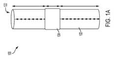
図1Aは、1つの実施形態による、弁付き導管人工器官100の側面図である。弁付き導管人工器官100は、導管102内に配置された弁構造104を有する導管102を含む。導管102は、弁構造104が流入端213から流出端215への一方向の流れを可能にするように動作可能であるように、流入端213及び流出端215を含む。 FIG. 1A is a side view of a
弁付き導管人工器官100は、非限定的な例において、大動脈弁及び上行大動脈の少なくとも一部を置換するために使用されうる。1つの非限定的な例において、弁付き導管人工器官100は、小児患者における大動脈根及び大動脈弁の矯正又は再建、すなわち大動脈根置換に適応されうる。弁付き導管人工器官100はまた、機能不全又は不十分になった、以前にインプラント処置された同種移植片又は弁付き導管の置換のために適用されうる。
弁付き導管人工器官100は、非限定的な例において、左心低形成症候群の治療のために頻繁に行われるノーウッド手術後に右心室を肺動脈に接続するためのシャントとして使用することができる。1つの非限定的な例において、弁付き導管人工器官100は、小児患者の右心室流出路(RVOT)の矯正又は再建に適用されうる。このような再建は、ファロー四徴症、大動脈の動脈幹右旋性転位、無傷の心室中隔の肺動脈閉鎖症、又は大動脈弁疾患などの先天性心疾患に適応されうる。弁付き導管人工器官100はまた、機能不全又は不十分になった、以前にインプラント処置された同種移植片又は弁付き導管の置換に適用されうる。さらに、弁付き導管人工器官100は、心臓の他の領域を含む、より広い範囲の心臓障害を治療する用途を有することができる。 The
一般に、「遠位」という用語は、本開示において、弁付き導管人工器官100の流出端215(遠位端)又は流出方向を指すために使用され、そして、「近位」という用語は、弁付き導管人工器官100の流入端213を指すために使用される。順行性又は順方向流は、流入端213から流出端215への流体の流れであり、閉じた弁構造104を通って漏れるときの逆流とも呼ばれる逆行性流は、流出端215から流入端213への流体の流れである。 In general, the term "distal" is used in this disclosure to refer to the outflow end 215 (distal end) or outflow direction of the
特定の実施形態において、導管102の内面110は、図1B及び図3に示されるように直径方向に一定である。さらに、弁尖106は、導管102の長さに沿った長手方向の位置で導管102内に配置されることができ(例えば、図1Aに示されるように)、導管102は、弁尖106が配置された長手方向の位置で、そして導管102の隣接近位部分及び遠位部分を通して直径方向に一定である。 In certain embodiments, the
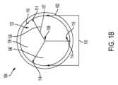
図1B及び1Cは、図1Aの実施形態による、それぞれ閉構成及び開構成における弁構造104の軸方向図を示す。弁構造104は、導管102の内面102から導管102の内部に延在する弁尖106を含む。弁構造104は、一方向弁として機能する1つ以上の別個の弁尖106又は一緒に結合された複数の弁尖106を有する弁尖構築物と定義される。3つの弁尖106が図1B及び図1Cに示されているが、弁構造104は、1つ、2つ、3つ、4つ又はそれ以上の数の弁尖106を含むことができる。図1Bに示されるように、弁尖106は、閉構成において導管102の中心108に向かって閉じる。開構成においては、図1Cに示されるように、血液は弁構造104を通って流れることができ、弁尖106は導管102の内面110に向かって押されている。1つの実施形態によると、弁尖106は、導管102の内面110が弁尖106自体によってのみ中断される流入端213から流出端215まで一貫した内径を有する滑らかな内部を有するように、導管102に弁構造104として結合されうる。下記に記載されるように、弁尖106は、導管102の外面320に結合されたタブ542によって導管102に結合され、一方、弁尖ベリー125は、導管内壁から導管管腔122内に延在している。 1B and 1C show axial views of
図1B及び1Cに示されるように、交連間隙114は、一対の弁尖106の間の各交連116に位置する。交連116は、交連間隙114を画定するランド112として、図4A~4Cに示されるように、弁尖自由端107で弁尖106の対の最も密な近接性の導管内面110での位置である。交連間隙114は、弁尖106が閉じているときに、導管102を通る逆行性流を可能にする。逆行性流は、血栓形成につながる可能性がある、血液が弁尖106の後ろに停滞する機会を減らすことができる。交連間隙114は、逆行性流に起因する漏れが最小限に抑えられ、さもなければ導管102を通して血液を送り出すための患者の心臓への負荷を増加させないようなサイズにされる。交連間隙114は、図4A~4Cに詳細に示されるように、導管102内のランド112に関連し、すなわち、最も密な近接性での隣接スリット434の間の空間に関連する。 As shown in FIGS. 1B and 1C, a
図2は、別の実施形態による、別の弁付き導管人工器官100の図である。弁付き導管人工器官100は、導管102及び弁構造104を含む。導管102は、流入端213を画定する流入部分212及び流出端215を画定する流出部分214を含む。導管102上の矢印によって示されるように、弁構造104は、血流が導管102を通って流入部分212から流出部分214に流れることを可能にし、血流が流出部分214から流入部分212に流れるのを防止するように構成されている。矢印は、導管102上に印刷されたデザイン特徴であることができ、それにより、導管102内の血流の方向を示し、適切なインプラント処置のために医師に方向指示することができる。矢印(方向インジケータ)は、多くの異なる形状、サイズ、長さであることができ、又はその他の考慮事項を含むことができる。 FIG. 2 is an illustration of another
図1Bを参照して上述したように、弁構造104は、1つ以上の弁尖106を含む。弁尖106は、導管102に結合され、導管102と組み合わせて、弁構造104を画定する。弁尖106は、限定するわけではないが、接着剤、熱結合及び化学結合などの適切な手段によって、導管102の外面320に結合される。1つの実施形態によれば、弁尖106は、図3に示されるように、接着フィルム216によって導管102に結合、取り付け、接着、貼り付け又はボンディングされる。 As described above with reference to FIG. 1B,
接着フィルム216は、導管102の周囲に巻き付けられた連続層又は不連続層であることができる。接着フィルム216は、弁尖106を導管102の外面に結合するために導管102の弁領域350内にあるかぎり、導管102の高密度化部分604で(図3を参照して議論される)及び/又は高密度化部分604を越えて、導管102の周囲に配置され又は巻き付けられることができる。他の実施形態において、接着フィルム216は、導管102の弁領域350に配置することができ、また導管102の弁領域350を越えて配置することができ、そして幾つかの実施形態において、導管102全体を覆うことができる。接着フィルム216は、血液が通って漏れるスリット434をシールすることができる。接着フィルム216は、図4B及び図4Cに示されるように、第一の導管102a及び第二の導管102bとして説明されるように、弁尖で突き合わせ接合される2つの導管を一緒に保持することができる。
図3に示されるように、例えば、接着剤、熱結合又は化学結合によって、弁尖を導管102の外面320に結合又は取り付けることは、滑らかな内面318及び一貫した導管内径を維持し、そして内面318のプロファイルに影響を与える取り付け構成と比較して、有効バルブオリフィス面積(EOA)を最大化した。 As shown in FIG. 3, bonding or attaching the leaflets to the
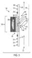
図3は、1つの実施形態による、弁付き導管人工器官100の断面図である。弁付き導管人工器官100は、内面318、外面320、近位(又は流入)部分212及び遠位(又は流出)部分214を有する導管102を含む。導管102は、導管102の内面318と外面320との間に開口部324を有する弁尖取り付け部分322を含む。以下に説明するように、開口部324は、図4A~4Cに示されるとおりのスリット434に対応することができ、それにより、不連続なスリット434をもたらし、又は、図4A及び4Cに示すように第一の導管102a及び第二の導管102bへの導管102の完全な分離をもたらすことができる。弁尖取り付け部分322は、導管102の一体部分であることができる。 FIG. 3 is a cross-sectional view of a
弁付き導管人工器官100はまた、導管102内に入り、そして導管の中心108に向かって延在する弁尖106を含む。図3に示されるように、弁尖106は、タブ542を介して導管102の外面320に結合される。弁尖106は、図3に示されるように、開口部324を介して導管102の外部に、そして導管102内に配置される部分を含み、弁尖ベリーは内面318から導管102内に延在する弁尖の部分として定義される。例として示されるこの実施形態によれば、弁尖106は接着フィルム216によって導管102の外面320に結合される。接着フィルム216は、タブ542上及び/又はスリット434又は開口部324上にオーバーレイされ又はオーバーラップされうる。限定するわけではないが、熱結合、接着結合及び機械的結合などの他の結合手段は考えられる。接着フィルム216は、弁尖取り付け部分322の境界内に配置されうる。さらに、弁尖取り付け部分322は、導管102の近位(又は流入)部分212及び遠位(又は流出)部分214と比較して高密度化されうるか、又はより高密度である材料特性を有することができ、高密度部分604として識別される。
弁尖取り付け部分322は、特定の目的のために、導管102の残りの部分に対して高密度化及び/又は剛性化されうる。例として、限定するわけではないが、取り扱い及び使用中に導管102が弁領域350でその形状を保持するように、高密度化された取り付け部分322を設けることができる。他の例として、限定するわけではないが、高密度化された取り付け部分322を設けて、流れの乱れを防止し及び/又は組織又はパンヌスの内部成長を防止するように、より滑らかな表面テクスチャ及び/又は気孔率の低減を提供することができる。高密度化とは、加熱及び/又は加圧、及び/又はエラストマー又はエラストマー性材料を細孔に吸収させることなどによって、選択された位置で材料を選択的により高密度にするプロセスを指す。特定の実施形態において、導管102は延伸ポリテトラフルオロエチレン(ePTFE)から形成される。比較的に多孔性であることができるePTFE材料では、高密度化プロセスにより、多孔性が低下し、及び/又はその領域がより硬くなる。 Leaflet mounting
弁付き導管人工器官100はまた、導管102及び接着フィルム216の周囲に配置された可撓性フィルム326を含むことができる。可撓性フィルム326は、特定の実施形態において、可撓性フィルム326の1つ以上の層を含むことができる。可撓性フィルム326は、導管102及び接着フィルム216の周りに複数回巻き付けられることができる。可撓性フィルム326は、必要に応じて巻き付けられて、導管102の強度及び/又は弁尖106の導管102への取り付けを強化し、及び/又はタブ542を結合し、及び/又はスリット434又は開口部324を漏出から密封し、及び/又は、例えば、図4B及び4Cに示されるように、第一の導管102a及び第二の導管102bとして記載されるように、弁尖106で突き合わせ接合される2つの導管を一緒に保持することができる。接着フィルム216は、弁尖106を導管102の外面320に結合するために導管102の弁領域350内にあるかぎり、導管102の弁尖取り付け部分322(例えば、図3を参照して論じられる)で、及び/又は弁尖取り付け部分322を越えて、導管102の周囲に配置され又は巻き付けられることができる。他の実施形態において、接着フィルム216は、導管102の弁領域350に、また、導管102の弁領域350を越えて配置することができ、そして幾つかの実施形態において、導管102全体を覆うことができる。
可撓性フィルム326は、例えば、導管102に柱強度を加えることによって、導管102の長手方向引張り強度を高める。可撓性フィルム326は、例えば、弁尖106が導管102の外面320に固定されることを確実にするために使用されうる。特定の実施形態において、上述のように、導管102はePTFEであることができる。特に適しているのは、曲げ/よじれ抵抗を備えた可変長さを提供するので、延伸性/弾性挙動を有するePTFE血管グラフトである。この点に関して、導管102の外面320は、内面318(管腔流れ面)、ひいては導管102の導管管腔122をねじることなく、解剖学的構造に適合するように伸長することができる。可撓性フィルム326はまた、ePTFEであることができ、ここで、接着フィルム216はフッ素化エチレンプロピレン(FEP)である。可撓性フィルム326及び接着フィルム216を組み合わせて使用することにより、弁尖106を導管102に(例えば、熱的に)結合することができる。
特定の実施形態において、弁付き導管人工器官100はまた、可撓性フィルム326によって、又は熱、接着、機械及び摩擦手段などの他の手段によって、導管102の外面320に結合された支持フレーム328を含むことができる。支持フレーム328は、解剖学的圧縮力及び/又は操作力により、導管102及び弁構造104の圧縮を防止するか、又はさもなければ圧縮性を低下させることができる。さらに、支持フレーム328は、特定の実施形態において、ポリエーテルエーテルケトン(PEEK)から形成される。これらの例において、支持フレーム328は放射線不透過性ではなく、したがって、支持フレーム328が視覚化を妨害する他の材料から形成された場合と比較して、医師は弁尖106及び弁尖取り付け部分322の位置をよりよく見ることができる。弁尖106及び/又は弁尖取り付け部分322を視覚化することにより、医師が導管102を正確に標的位置を位置確認して、そこに配置する能力を高めることができる。他の例において、支持フレーム328は、位置決め又は手術後のインプラント処置の位置確認の補助として、放射線不透過性材料から形成される。他の例において、支持フレーム328は、ステンレス鋼などの金属であり、他の材料と比較して、耐クラッシュ性を提供しながら、図11に示すように、導管102の外面320のプロファイルを低くする(例えば、より薄くする)ことができる。 In certain embodiments, the
支持フレーム328は、放射線不透過性であっても又はなくてもよい。特定の例において、弁付き導管人工器官100は、蛍光透視下で処置後の導管102の弁領域350を視覚化するのを支援するために、1つ以上の放射線不透過性マーカー330を含むことができる。1つ以上の放射線不透過性マーカー330は、導管102の外面320上で弁尖106に隣接して配置することができる。特定の実施形態において、図3に示されるように、弁付き導管人工器官100は、弁尖106及び弁尖取り付け部分322の長手方向の両側に放射線不透過性マーカー330を含んでもよく、また、流れの可視化及び流れの分析を支援するために、限定するわけではないが、交連116などで弁尖106と半径方向に位置合わせして配置されてもよい。このようにして、医師は、弁尖106及び弁尖取り付け部分322をより具体的には標的位置に配置又は位置確認するためのマーカーを有する。特定の実施形態において、放射線不透過性マーカー330は、導管102の周囲に巻き付けられるか、又は配置された、放射線不透過性材料(例えば、金)の連続又は不連続なリボンである。
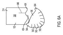
図4Aは、単一の導管構成要素が利用される実施形態による、弁付き導管人工器官100で使用されるときの導管102のための切断パターン432の図である。切断パターン432は、複数の別個のスリット434を含む(例えば、図3に示される開口部324を作成する)。スリット434は、導管102に結合される、図3に示される弁尖106の数に対応する。図4Aに示されるように、切断パターン432によって画定される複数のスリット434は相互接続されていない。したがって、導管102は、組み立て中に複数の部品に分離されず、単一の導管構成要素が利用される。2つのスリット434が図4Aに示されているが、切断パターン432は、追加のスリット(例えば、3つの弁尖の三尖弁におけるような3つのスリット、4つのスリットなど)を有してもよい。スリット434は、レーザ切断、手切断又は他の同様の方法によって形成されうる。図4A~4Cに示される実施形態において、各スリット434は放物線形状を画定し、対応する弁尖106は、内面318で導管102を貫通する放物線形状を有する。弁領域350が長手方向に切断され、開いて平らに置かれている状態で視覚化されたときに、平らな基部と2つのまっすぐな側辺を有する弁尖106を画定するように等脚台形の3つの辺を画定する。図5に示されているタブ542及び544は、図6Cに示されるように、導管102の内側からスリット434を通過され、外面320に取り付けられることができる。 FIG. 4A is an illustration of a
スリット434はランド112によって分離されており、ここで2つの弁尖106が近接して交連116を画定している。上記のように、スリット434は、導管102に結合された弁尖(図示せず)の数に対応する。ランド112は、交連116(図1B及び1Cに示される)、すなわち、導管102内の弁尖106間の分離に対応する。弁尖106が閉位置にある(例えば、弁構造が閉鎖されている)ときに、図1Bに示されるように、弁尖106間に空間、すなわち交連間隙114が存在する。同様に、弁尖106が開位置にあるときに、図1Cに示すように、弁尖106間に空間、すなわち交連間隙114が存在する。スリット434及びランド112は、導管102に結合された弁尖の数に対応する。交連間隙114は、弁尖が閉位置にあるときに血液が弁尖106の背後の領域を洗い流すことを可能にする。交連間隙114を通る逆行性流又は逆流は、血栓形成につながる可能性がある、血液が弁尖106の後ろに停滞する機会を減少させる。交連間隙114は、結果として生じる逆行性流が最小限であるように、さもなければ、導管102を通して血液を送り出すための患者の心臓への負荷を増やさないようにサイズ決めされる。交連間隙114はまた、弁尖106が開位置にあるときに、交連での流体流を増加させ、それにより、例えば、限定するわけではないが、交連間隙114が提供されない場合に起こりうる2つの密接に対向する弁尖表面の間の血液の捕捉がないようにする。
図4Bは、1つの実施形態による、弁付き導管人工器官100で使用されるときの導管102のための切断パターン436の図である。切断パターン436は、複数の別個のスリット434を含み、スリット434の数は、導管102に結合される弁尖(図示せず)の数に対応する。切断パターン436はまた、導管102が、組み立てのために2つの導管構成要素、すなわち、図4Bに示すように第一の導管102a及び第二の導管102bに分割されうる導管102における側方切り込み438を含む。側方切り込み438は、スリット434の長手方向部分の近くに、それに隣接して、又はそれの中間点に配置される。側方切り込み438及びスリット434は、レーザ切断、手切断又は他の同様の方法によって形成されうる。2つのスリット434が図4Bに示されているが、切断パターン436は、追加のスリット(例えば、三尖弁におけるような3つの弁尖106の弁のための3つのスリット、4つのスリットなど)を有することができる。 FIG. 4B is an illustration of a cutting pattern 436 for
スリット434及び側方切り込み438は、導管102に結合される弁尖の数に対応する。図4Aと同様に、スリット434はランド112によって分離されている。ランド112は、導管102内の弁尖106間の分離(例えば、交連で)に対応する。弁尖106が閉じているときに(例えば、弁が閉じているときに)、図1に示されるように、弁尖の間に空間、すなわち交連間隙114が存在する。交連間隙114は、先に述べたように、弁尖が閉位置にあるときに、血液が弁尖の背後の領域を洗い流すことを可能にする。逆行性流は、血栓の形成につながる可能性がある、血液が弁尖106の後ろに停滞する機会を減少させる。交連間隙114は、結果として生じる逆行性流が最小限であり、さもなければ、導管102を通して血液を送り出すための患者の心臓への負荷を増やさないようにサイズ決めされる。交連間隙114はまた、弁尖106が開位置にあるときに、交連での流体流を増加させることができ、それにより、例えば、限定するわけではないが、交連間隙114が提供されない場合に起こりうる2つの密接に対向する弁尖表面の間の血液の捕捉がないようにする。
図4Cは、1つの実施形態による、弁付き導管人工器官で使用されるときの導管102のための別の例示的な切断パターン440の図である。 FIG. 4C is an illustration of another
切断パターン440は、導管102に結合される弁尖(図示せず)の数に対応する数のスリットを有する複数の別個のスリット434を含む。切断パターン440はまた、導管102におけるカットでもある側方切り込み438を含み、導管102が、第一の導管102a及び第二の導管102bを画定する、図4Cに示されるような、組み立てのための2つの導管構成要素に切断されることが可能になる。側方切り込み438及びスリット434は、レーザ切断、手切断又は他の同様の方法によって形成されうる。2つのスリット434が図4Bに示されているが、切断パターン440は、追加のスリット(例えば、三尖弁用の3つのスリット、4つのスリットなど)を有することができる。 Cutting
上述のように、スリット434及び側方切り込み438は、導管102に結合される弁尖の数に対応する。図4Aと同様に、スリット434はランド112によって分離されている。ランド112は交連ギャップ114に対応し、これは、弁が閉じているときの導管102内の弁尖間の分離である(例えば、弁尖が閉位置にあるときに交連間隙114を維持する)。 As noted above, slits 434 and
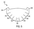
図5は、1つの実施形態による、弁付き導管人工器官100の実施形態で使用されうる弁尖106である。図5に示すように、弁尖106は、弁尖ベリー125から延在し、それを画定する複数のタブ542を含むことができる。タブ542は、弁尖106の縁にスリットを切断することによって形成することができる。弁尖106は、以下で論じられるように、薄いシート状の材料から形成される。図6A~Cを参照してさらに詳細に示されるように、タブ542は、図3にも示されるように、弁尖106を導管102の外面320に結合するために使用されうる。 FIG. 5 is a
特定の実施形態において、弁尖106は、弁尖の自由端に隣接するタブ544である位置合わせタブ544を含む。位置合わせタブ544は、タブ542と同じ方法で形成される。位置合わせタブ544は、弁尖106に存在するときに、導管102とインターフェースして、弁尖106を導管102に取り付けるために交連116で位置合わせするのを補助するために使用される。 In certain embodiments,
図6Aは、1つの実施形態による、弁尖106を導管102に取り付ける例示の工程を示す図である。説明を容易にするために、導管102の流出部分214は図6Aに示されている。しかしながら、図4Aを参照して述べたように、導管102及び弁尖106は、導管102を複数のセクションに分離することなく一緒に結合されうる。 FIG. 6A illustrates an exemplary process of attaching
弁尖106は、導管102内でスリット434と位置合わせされる。上述のように、複数の弁尖106を導管102に結合することができる。説明を容易にするために、図6A~Cは、導管102への単一弁尖106の取り付けを示す。特定の実施形態において、導管102は、導管102に沿って長手方向に延在する位置合わせ線646を含む。位置合わせ線646は、導管102内で弁尖106の位置合わせを容易にする。特定の実施形態において、弁尖106は、導管102内の弁尖106の形状及び位置合わせが適切であることを確実にするために、位置合わせ線646に対して配置される位置合わせタブ544を含む。他の実施形態において、交連116でのスリット434は、弁尖106の導管102への位置合わせを支援するために使用される。
弁尖106がスリット434と位置合わせされると、タブ542を、導管102の外面306上に折り畳むことができる。図6Bに示すように、位置合わせタブ544を、位置合わせ線646と位置合わせするように折り畳むことができる。 Once
図6Cに示されるように、タブ542は、異なる方向に折り畳むことができる。交互のタブ542を、例えば、導管102の近位(又は流入)部分212及び遠位(又は流出)部分214の外面320に対して折り畳むことができる。タブ542(及び位置合わせタブ544)は弁尖106の取り付けセクションであることができ、それは、導管102の外面320に、例えば、限定するわけではないが、接着剤、熱結合又は化学結合(例えば、図6A~6Cを参照して上で詳述したとおり)によって結合されうる。弁尖106のタブ542は、近位(又は流入)部分212と遠位(又は流出)部分214との間に画定された導管102内のスリット434(例えば、図3に示されるとおり)を通って延在する。弁尖106の残りの部分、弁尖ベリー125は、導管102の導管管腔122内に延在し、弁付き導管人工器官100内の弁として機能するように動作可能である。 As shown in FIG. 6C,
本明細書で論じる弁付き導管人工器官は、外科手術において病気の解剖学的構造を置換するために使用される。インプラント処置前に、弁付き導管人工器官を生理食塩水ですすぐことができ、事前凝固を必要としない。1つの治療方法によれば、弁付き導管人工器官は、大動脈根置換などにおいて、大動脈弁及び上行大動脈の一部の置換として使用される。弁付き導管人工器官のインプラント処置は、導管の流入部分及び流出部分を特定すること、解剖学的構造に関して意図された位置にアクセスすること、及び、場合により、適度な張力をかけながら、インプラント処置に適切な長さに流入及び/又は流出導管をトリミングすることを含む。上行大動脈を切断し、弁付き導管人工器官の流入部分及び/又は流入端を、切除された大動脈弁に隣接して、又はそれを置換して、左心室に縫合又は別の方法で結合する。弁付き導管人工器官の流出部分及び/又は流出端を、切断された上行大動脈に縫合する。冠状動脈は上行大動脈に留まることができ、又は、導管の流出部分に縫合され、導管管腔から冠状動脈への流路が提供される。 The valved duct prostheses discussed herein are used in surgical procedures to replace diseased anatomy. Prior to the implant procedure, the valved duct prosthesis can be rinsed with saline and does not require pre-coagulation. According to one method of treatment, a valved conduit prosthesis is used as a replacement for a portion of the aortic valve and ascending aorta, such as in aortic root replacement. Implantation of a valved duct prosthesis involves identifying the inflow and outflow portions of the duct, accessing the intended location with respect to the anatomy, and, optionally, under appropriate tension, the implantation procedure. including trimming the inflow and/or outflow conduits to the appropriate length. The ascending aorta is cut and the inflow portion and/or inflow end of the valved conduit prosthesis is sutured or otherwise attached to the left ventricle adjacent to or replacing the resected aortic valve. The outflow portion and/or outflow end of the valved conduit prosthesis is sutured to the severed ascending aorta. The coronary artery may remain in the ascending aorta or may be sutured to the outflow portion of the conduit to provide a flow path from the conduit lumen to the coronary artery.
別の治療方法によれば、弁付き導管人工器官100は、天然の肺動脈弁又は以前にインプラント処置された肺動脈弁付き導管人工器官の置換物であることができ、ここで、右心室流出路及び/又は主肺動脈の部分的又は完全な再建が望まれる。特定の例において、弁付き導管人工器官のインプラント処置は、導管の流入部分及び流出部分を特定すること、インプラント処置時に冠状動脈の圧迫のリスクがないことを保証するために冠状動脈に関して意図された位置にアクセスすること、及び、場合により、流入及び/又は流出導管を、適度な張力をかけながら、インプラント処置に適した長さにトリミングすることを含む。 According to another treatment method, the
患者の大動脈根を置換することによって大動脈弁疾患を治療する別の方法によれば、この方法は、本明細書の実施形態に従って弁付き導管人工器官100を提供すること、及び、図7に示されるように、弁付き導管人工器官100を外科的にインプラント処置することの工程を含む。この方法は、さらに、導管102の流入部分212及び流出部分214を特定すること、解剖学的構造に関して意図した位置にアクセスすること、場合により、導管の流入部分212及び流出部分214を、インプラント処置に適した長さにトリミングすること、場合により、流入端213を外向きにテーパーにするか、又は、場合により、弁尖構造104に向かって流入部分212を反転して巻いて、縫合カフ130を画定すること、上行大動脈を切断すること、弁付き導管人工器官100の流入部分212を、切除された大動脈弁に隣接して又はそれを置換して、左心室に結合すること、及び、弁付き導管人工器官100の流出部分214を、切断された上行大動脈に結合することを含むことができる。この方法は、冠状動脈128を導管102の流出部分214に結合すること、及び、導管管腔122から冠状動脈128への流路を確立することをさらに含むことができる。この方法は、冠状動脈128を、流出部分によって画定される湾曲部126に結合することをさらに含むことができる。 According to another method of treating aortic valve disease by replacing a patient's aortic root, the method comprises providing a
弁尖材料
膨張フルオロポリマー膜は、所望の弁尖性能を達成するために、細孔などの任意の適切な微細構造を含むことができる。弁尖での使用に適することができる他の生体適合性ポリマーとしては、限定するわけではないが、ウレタン、シリコーン(オルガノポリシロキサン)、シリコン-ウレタンのコポリマー、スチレン/イソブチレンコポリマー、ポリイソブチレン、ポリエチレン-コ-ポリ(酢酸ビニル)、ポリエステルコポリマー、ナイロンコポリマー、フッ素化炭化水素ポリマー、及び上述のそれぞれのコポリマー又は混合物の群が挙げられる。Leaflet Material The expanded fluoropolymer membrane can include any suitable microstructure, such as pores, to achieve the desired leaflet performance. Other biocompatible polymers that may be suitable for use in leaflets include, but are not limited to, urethanes, silicones (organopolysiloxanes), silicone-urethane copolymers, styrene/isobutylene copolymers, polyisobutylene, polyethylene. - co-poly(vinyl acetate), polyester copolymers, nylon copolymers, fluorinated hydrocarbon polymers, and copolymers or mixtures of each of the above.
様々な例において、本明細書に記載の弁尖106(例えば、弁尖構築物)のいずれも、生体適合性の合成材料(例えば、ePTFE及びePTFE複合材料、又は所望に応じて他の材料を含む)から形成されうる。合成弁尖での使用に適することができる他の生体適合性ポリマーとしては、限定するわけではないが、ウレタン、シリコーン(オルガノポリシロキサン)、シリコン-ウレタンのコポリマー、スチレン/イソブチレンコポリマー、ポリイソブチレン、ポリエチレン-コ-ポリ(酢酸ビニル)、ポリエステルコポリマー、ナイロンコポリマー、フッ素化炭化水素ポリマー、及び、上述のそれぞれのコポリマー又は混合物の群が挙げられる。 In various examples, any of the leaflets 106 (e.g., leaflet constructs) described herein comprise biocompatible synthetic materials (e.g., ePTFE and ePTFE composites, or other materials as desired). ). Other biocompatible polymers that may be suitable for use in synthetic valve leaflets include, but are not limited to, urethanes, silicones (organopolysiloxanes), silicone-urethane copolymers, styrene/isobutylene copolymers, polyisobutylene, Groups include polyethylene-co-poly(vinyl acetate), polyester copolymers, nylon copolymers, fluorinated hydrocarbon polymers, and copolymers or mixtures of each of the above.
他の例において、そのような弁尖構築物は、ウシ組織、ブタ組織などを含む再利用された組織などの天然材料から形成される。 In other examples, such leaflet constructs are formed from natural materials such as recycled tissue, including bovine tissue, porcine tissue, and the like.
「エラストマー」という用語は、元の長さの少なくとも1.3倍に伸ばされ、解放されたときにほぼ元の長さに急速に収縮する能力を有するポリマー又はポリマーの混合物を指す。 The term "elastomer" refers to a polymer or mixture of polymers that has the ability to be stretched to at least 1.3 times its original length and to rapidly contract to approximately its original length when released.
「エラストマー性材料」という用語は、必ずしも同程度の伸張及び/又は回復ではないが、エラストマーと同様の伸張及び回復特性を示すポリマー又はポリマーの混合物を指す。 The term "elastomeric material" refers to a polymer or mixture of polymers that exhibit similar stretch and recovery properties to elastomers, although not necessarily to the same extent.
「非エラストマー性材料」という用語は、エラストマー又はエラストマー性材料のいずれにも似ていない、すなわち、一般に知られているようなエラストマー又はエラストマー性材料ではないと考えられる伸縮及び回復特性を示すポリマー又はポリマーの混合物を指す。 The term "non-elastomeric material" means a polymer or material that exhibits stretch and recovery properties that would not resemble either an elastomer or an elastomeric material, i.e., not an elastomer or elastomeric material as it is commonly known. It refers to a mixture of polymers.
本明細書の実施形態によれば、弁尖106は、複数の細孔及び/又は空間を有する少なくとも1つの多孔質合成ポリマー膜層と、前記少なくとも1つの合成ポリマー膜層の細孔及び/又は空間を充填するエラストマー及び/又はエラストマー性材料及び/又は非エラストマー性材料とを有する複合材料を含む。他の例によれば、弁尖106は、複合材料上にエラストマー及び/又はエラストマー性材料及び/又は非エラストマー性材料の層をさらに含む。例によれば、複合材料は、質量基準で10%~90%の範囲の多孔質合成ポリマー膜を含む。 According to embodiments herein, the
多孔質合成ポリマー膜の例としては、細孔及び/又は空間を画定するノード及びフィブリル構造を有する膨張(膨張、エキスパンデッド、延伸又は発泡)フルオロポリマー膜が挙げられる。幾つかの例において、膨張フルオロポリマー膜は延伸ポリテトラフルオロエチレン(ePTFE)膜である。多孔質合成ポリマー膜の別の例としては、微孔質ポリエチレン膜が挙げられる。 Examples of porous synthetic polymer membranes include expanded (swollen, expanded, stretched or foamed) fluoropolymer membranes having a node and fibril structure defining pores and/or spaces. In some examples, the expanded fluoropolymer membrane is an expanded polytetrafluoroethylene (ePTFE) membrane. Another example of a porous synthetic polymer membrane is a microporous polyethylene membrane.
エラストマー及び/又はエラストマー性材料及び/又は非エラストマー性材料の例としては、限定するわけではないが、テトラフルオロエチレンとペルフルオロメチルビニルエーテルとのコポリマー(TFE/PMVEコポリマー)、(ペル)フルオロアルキルビニルエーテル(PAVE)、ウレタン、シリコーン(オルガノポリシロキサン)、シリコン-ウレタンのコポリマー、スチレン/イソブチレンコポリマー、ポリイソブチレン、ポリエチレン-コ-ポリ(酢酸ビニル)、ポリエステルコポリマー、ナイロンコポリマー、フッ素化炭化水素ポリマー、及び上述のそれぞれのコポリマー又は混合物が挙げられる。幾つかの例において、TFE/PMVEコポリマーは、60~20質量パーセントのテトラフルオロエチレンと、それぞれ40~80質量パーセントのペルフルオロメチルビニルエーテルとを含むエラストマーである。幾つかの例において、TFE/PMVEコポリマーは、67~61質量パーセントのテトラフルオロエチレンと、それぞれ33~39質量パーセントのペルフルオロメチルビニルエーテルとを含むエラストマー性材料である。幾つかの例において、TFE/PMVEコポリマーは、73~68質量パーセントのテトラフルオロエチレンと、それぞれ27~32質量パーセントのペルフルオロメチルビニルエーテルとを含む非エラストマー性材料である。TFE-PMVEコポリマーのTFE及びPMVE成分は、wt%で表される。参考までに、40、33~39及び27~32のPMVEのwt%は、それぞれ29、23~28及び18~22のモル%に対応する。 Examples of elastomers and/or elastomeric materials and/or non-elastomeric materials include, but are not limited to, copolymers of tetrafluoroethylene and perfluoromethyl vinyl ethers (TFE/PMVE copolymers), (per)fluoroalkyl vinyl ethers ( PAVE), urethanes, silicones (organopolysiloxanes), silicone-urethane copolymers, styrene/isobutylene copolymers, polyisobutylene, polyethylene-co-poly(vinyl acetate), polyester copolymers, nylon copolymers, fluorinated hydrocarbon polymers, and the above each copolymer or mixture of In some examples, the TFE/PMVE copolymer is an elastomer comprising 60-20 weight percent tetrafluoroethylene and 40-80 weight percent perfluoromethyl vinyl ether, respectively. In some examples, the TFE/PMVE copolymer is an elastomeric material comprising 67-61 weight percent tetrafluoroethylene and 33-39 weight percent perfluoromethyl vinyl ether, respectively. In some examples, the TFE/PMVE copolymer is a non-elastomeric material comprising 73-68 weight percent tetrafluoroethylene and 27-32 weight percent perfluoromethyl vinyl ether, respectively. The TFE and PMVE components of the TFE-PMVE copolymer are expressed in wt%. For reference, PMVE wt% of 40, 33-39 and 27-32 correspond to mol% of 29, 23-28 and 18-22 respectively.
幾つかの例において、TFE-PMVEコポリマーは、エラストマー、エラストマー性及び/又は非エラストマー性特性を示す。 In some instances, the TFE-PMVE copolymer exhibits elastomeric, elastomeric and/or non-elastomeric properties.
幾つかの例において、複合材料は、73~68質量パーセントのテトラフルオロエチレン及びそれぞれ27~32質量パーセントのペルフルオロメチルビニルエーテルを含むTFE-PMVEコポリマーの層又はコーティングをさらに含む。 In some examples, the composite material further includes a layer or coating of TFE-PMVE copolymer comprising 73-68 weight percent tetrafluoroethylene and 27-32 weight percent perfluoromethyl vinyl ether, respectively.
幾つかの例において、弁尖106は、60~20質量パーセントのテトラフルオロエチレン及びそれぞれ40~80質量パーセントのペルフルオロメチルビニルエーテルを含むTFE-PMVEコポリマーが吸収された延伸ポリテトラフルオロエチレン(ePTFE)膜であり、弁尖106は、さらに、血液接触表面上に73~68質量パーセントのテトラフルオロエチレン及びそれぞれ27~32質量パーセントのペルフルオロメチルビニルエーテルを含むTFE-PMVEコポリマーのコーティングを含む。 In some examples, the
上述のように、エラストマー及び/又はエラストマー性材料及び/又は非エラストマー性材料は、エラストマー及び/又はエラストマー性材料及び/又は非エラストマー性材料が膨張フルオロポリマー膜内の空隙又は細孔の実質的にすべてを占めるように、膨張フルオロポリマー膜と組み合わせることができる。 As noted above, the elastomer and/or elastomeric material and/or non-elastomeric material substantially fills the voids or pores within the expanded fluoropolymer membrane. It can be combined with an expanded fluoropolymer membrane to occupy the whole.
適切な弁尖材料の幾つかの例が提供されたが、上述の例は限定的な意味で読まれることを意図しておらず、追加又は代替の材料が考えられる。 Although some examples of suitable leaflet materials have been provided, the above examples are not intended to be read in a limiting sense and additional or alternative materials are contemplated.
本開示の発明的特徴は、一般的にそして特定の実施形態に関しての両方で上記に説明されてきた。本開示の範囲から逸脱することなく、実施形態に様々な変更及び変形を加えることができることが当業者に明らかであろう。したがって、実施形態は、添付の特許請求の範囲及びそれらの均等形態の範囲内にあるかぎり、本開示の変更及び変形を網羅することが意図されている。 Inventive features of this disclosure have been described above both generically and with regard to specific embodiments. It will be apparent to those skilled in the art that various modifications and variations can be made to the embodiments without departing from the scope of this disclosure. Thus, the embodiments are intended to cover the modifications and variations of this disclosure insofar as they come within the scope of the appended claims and their equivalents.
本開示の発明的特徴は、一般的にそして特定の実施形態に関しての両方で上記に説明されてきた。本開示の範囲から逸脱することなく、実施形態に様々な変更及び変形を加えることができることが当業者に明らかであろう。したがって、実施形態は、添付の特許請求の範囲及びそれらの均等形態の範囲内にあるかぎり、本開示の変更及び変形を網羅することが意図されている。
(態様)
(態様1)
導管管腔及びそれを通るスロットを画定する外面及び内面を有する導管、及び、
一方向弁として動作可能であるように、導管の外面に結合された外部部分と、導管の内面内に配置された内部部分とを有する少なくとも1つの弁尖であって、弁構造を画定する弁尖、
を含む、弁付き導管人工器官。
(態様2)
前記少なくとも1つの弁尖の外部部分は、接着剤、熱結合又は化学結合によって前記導管の外面に結合されている、態様1記載の弁付き導管人工器官。
(態様3)
態様1記載の弁付き導管人工器官。
(態様4)
前記接着フィルムは前記導管の周囲に配置されている、態様3記載の弁付き導管人工器官。
(態様5)
前記導管及び接着フィルムの周囲に配置された可撓性フィルムをさらに含む、態様4記載の弁付き導管人工器官。
(態様6)
前記可撓性フィルムは延伸ポリテトラフルオロエチレン(ePTFE)を含み、そして前記接着フィルムはフッ素化エチレンプロピレン(FEP)を含む、態様1~5のいずれか1項記載の弁付き導管人工器官。
(態様7)
前記可撓性フィルムによって前記導管に結合された支持フレームをさらに含む、態様1~6のいずれか1項記載の弁付き導管人工器官。
(態様8)
前記支持フレームはポリエーテルエーテルケトン(PEEK)から形成されている、態様7記載の弁付き導管人工器官。
(態様9)
前記導管の外面上で前記少なくとも1つの弁尖に隣接して配置された少なくとも1つの放射線不透過性マーカーをさらに含む、態様1~8のいずれか1項記載の弁付き導管人工器官。
(態様10)
前記導管の内面は直径方向に一定であり、巨視的な中断がない、態様1~9のいずれか1項記載の弁付き導管人工器官。
(態様11)
前記少なくとも1つの弁尖は、前記導管の長さに沿った長手方向の位置で前記導管内に配置され、前記導管は、前記少なくとも1つの弁尖が配置される長手方向の位置で、前記導管の隣接する近位部分及び遠位部分を通って直径方向に一定である、態様1~10のいずれか1項記載の弁付き導管人工器官。
(態様12)
前記導管は、流入端を画定する流入部分及び流出端を画定する流出部分を有し、前記少なくとも1つの弁尖は、順行性流れ状態で前記導管の流入端からの流れが流出端を通過できるように開くように動作可能であり、そして逆行性流れ状態で流出端からの流れが流入端を通って流れるのを制限するように閉じるように動作可能である、態様1~11のいずれか1項記載の弁付き導管人工器官。
(態様13)
前記少なくとも1つの弁尖は、細孔を画定する多孔質合成フルオロポリマー膜と、前記細孔を充填するエラストマー又はエラストマー性材料とを含む複合材料、及び、
場合により、前記複合材料の少なくとも一部の上に、27~32質量パーセントのペルフルオロメチルビニルエーテル及びそれぞれ73~68質量パーセントのテトラフルオロエチレンを含むTFE-PMVEコポリマー、
を含み、
そして、場合により、前記エラストマー又はエラストマー性材料はTFE-PMVEコポリマーを含み、
そして、場合により、前記多孔質合成フルオロポリマー膜はePTFEである、態様1~12のいずれか1項記載の弁付き導管人工器官。
(態様14)
前記流出部分は、前記少なくとも1つの弁尖に隣接する湾曲部を画定する、態様12及び13のいずれか1項記載の弁付き導管人工器官。
(態様15)
前記湾曲部は、血管及び/又は冠状動脈の外科的取り付けのために動作可能である、態様14記載の弁付き導管人工器官。
(態様16)
前記流入端は外向きテーパーを画定するか、又は外向きテーパーとなるように動作可能である、態様1~15のいずれか1項記載の弁付き導管人工器官。
(態様17)
前記流入部分は外向きに反転され、弁構造に向かって巻かれ、縫合カフを画定するように動作可能である、態様1~15のいずれか1項記載の弁付き導管人工器官。
(態様18)
導管管腔を画定する内面、外面、近位部分及び遠位部分を有する導管、
前記導管の内面と外面との間に開口部を有する弁尖取り付け部分、及び、
前記導管の外面に結合された取り付けセクションを有する少なくとも1つの弁尖であって、弁構造を画定する、少なくとも1つの弁尖、
を含む、弁付き導管人工器官。
(態様19)
前記少なくとも1つの弁尖は3つの弁尖を含み、前記3つの弁尖は交連間隙によって導管の内部で互いに分離されている、態様18記載の弁付き導管人工器官。
(態様20)
前記導管は、前記導管の内面内の前記3つの弁尖の間に前記交連間隙を形成するために、前記弁尖の各々の前記取り付けセクションで前記弁尖を分離するランドを含む、態様19記載の弁付き導管人工器官。
(態様21)
前記取り付けセクションは、接着剤、熱結合又は化学結合によって前記導管の外面に取り付けられる、態様19記載の弁付き導管人工器官。
(態様22)
前記取り付けセクションは第一の部分及び第二の部分を含み、前記第一の部分は、前記導管の外面の近位部分に取り付けられ、そして前記第二の部分は、前記導管の外面の遠位部分に取り付けられている、態様19記載の弁付き導管人工器官。
(態様23)
前記弁尖取り付け部分は導管の一部であり、前記弁尖取り付け部分は前記導管の残りの部分より高密度である、態様19記載の弁付き導管人工器官。
(態様24)
前記導管の外面上に方向インジケータをさらに含み、前記導管内での血流の方向を示す、態様18~23のいずれか1項記載の弁付き導管人工器官。
(態様25)
前記導管は、流入端を画定する流入部分及び流出端を画定する流出部分を有し、前記少なくとも1つの弁尖は導管に結合され、前記流入端からの流れが順行性流状態で前記導管の流出端を通過できるように開くように動作可能であり、そして逆行性流状態で流出端から前記導管流入端を通って流れが流れるのを制限するように閉じるように動作可能である、態様18~24のいずれか1項記載の弁付き導管人工器官。
(態様26)
前記少なくとも1つの弁尖は、細孔を画定する多孔質合成フルオロポリマー膜と、前記細孔を充填するエラストマー又はエラストマー性材料とを含む複合材料、及び、
場合により、前記複合材料の少なくとも一部の上に、27~32質量パーセントのペルフルオロメチルビニルエーテル及びそれぞれ73~68質量パーセントのテトラフルオロエチレンを含む、TFE-PMVEコポリマー、
を含み、そして、場合により、前記エラストマー又はエラストマー性材料は、TFE-PMVEコポリマーを含み、
そして、場合により、前記多孔質合成フルオロポリマー膜はePTFEである、態様18~21のいずれか1項記載の弁付き導管人工器官。
(態様27)
前記流出部分は、前記少なくとも1つの弁尖に隣接する湾曲部を画定する、態様18~26のいずれか1項記載の弁付き導管人工器官。
(態様28)
前記湾曲部は、血管及び/又は冠状動脈の外科的取り付けのために動作可能である、態様27記載の弁付き導管人工器官。
(態様29)
前記流入端は外向きテーパーを画定するか、又は外向きテーパーとなるように動作可能である、態様18~28のいずれか1項記載の弁付き導管人工器官。
(態様30)
前記流入部分は外向きに反転され、弁構造に向かって巻かれ、縫合カフを画定するように動作可能である、態様18~28のいずれか1項記載の弁付き導管人工器官。
(態様31)
大動脈根を置換することによって大動脈弁疾患を治療する方法であって、態様1~22のいずれか1項記載の弁付き導管人工器官を提供すること、及び、前記弁付き導管人工器官を外科的にインプラント処置することを含む、方法。
(態様32)
前記導管の流入部分及び流出部分を特定すること、
解剖学的構造に関して意図された位置にアクセスすること、
場合により、前記導管の流入部分及び流出部分を、インプラント処置に適する長さにトリミングすること、
場合により、流入端を外向きにテーパーとするか、又は、場合により、流入部分を弁尖構造に向かって反転させて巻き、縫合カフを画定すること、
上行大動脈を切断すること、
前記弁付き導管人工器官の流入部分を、切除された大動脈弁に隣接して又はその置換として左心室に結合すること、及び、
前記弁付き導管人工器官の流出部分を、切断された上行大動脈に結合すること、
をさらに含む、態様31記載の方法。
(態様33)
冠状動脈を前記導管の流出部分に結合すること、及び、
前記導管管腔から冠状動脈への流路を確立すること、
をさらに含む、態様32記載の方法。
(態様34)
冠状動脈を結合することは、前記流出部分によって画定される湾曲部に冠状動脈を結合することを含む、態様33記載の方法。Inventive features of this disclosure have been described above both generically and with regard to specific embodiments. It will be apparent to those skilled in the art that various modifications and variations can be made to the embodiments without departing from the scope of this disclosure. Thus, the embodiments are intended to cover the modifications and variations of this disclosure insofar as they come within the scope of the appended claims and their equivalents.
(mode)
(Aspect 1)
a conduit having an outer surface and an inner surface defining a conduit lumen and a slot therethrough; and
At least one valve leaflet defining a valve structure having an outer portion coupled to the outer surface of the conduit and an inner portion disposed within the inner surface of the conduit so as to be operable as a one-way valve. point,
A valved conduit prosthesis, comprising:
(Aspect 2)
2. The valved conduit prosthesis of aspect 1, wherein the outer portion of the at least one leaflet is bonded to the outer surface of the conduit by an adhesive, thermal bond or chemical bond.
(Aspect 3)
A valved duct prosthesis according to aspect 1.
(Aspect 4)
4. The valved duct prosthesis of aspect 3, wherein the adhesive film is disposed about the duct.
(Aspect 5)
5. The valved duct prosthesis of aspect 4, further comprising a flexible film disposed about the duct and adhesive film.
(Aspect 6)
6. The valved duct prosthesis of any one of aspects 1-5, wherein the flexible film comprises expanded polytetrafluoroethylene (ePTFE) and the adhesive film comprises fluorinated ethylene propylene (FEP).
(Aspect 7)
7. The valved duct prosthesis of any one of aspects 1-6, further comprising a support frame coupled to the duct by the flexible film.
(Aspect 8)
8. The valved duct prosthesis of aspect 7, wherein the support frame is formed from polyetheretherketone (PEEK).
(Aspect 9)
9. The valved duct prosthesis of any one of aspects 1-8, further comprising at least one radiopaque marker positioned adjacent said at least one leaflet on the outer surface of said duct.
(Mode 10)
10. The valved conduit prosthesis of any one of aspects 1-9, wherein the inner surface of the conduit is diametrically constant and free of macroscopic discontinuities.
(Aspect 11)
The at least one leaflet is disposed within the conduit at a longitudinal location along the length of the conduit, and the conduit is positioned at the longitudinal location where the at least one leaflet is disposed. 11. The valved duct prosthesis of any one of aspects 1-10, which is diametrically constant through adjacent proximal and distal portions of the valved duct prosthesis of any one of aspects 1-10.
(Aspect 12)
The conduit has an inflow portion defining an inflow end and an outflow portion defining an outflow end, and the at least one valve leaflet is configured such that flow from the inflow end of the conduit passes through the outflow end in antegrade flow conditions. 12. Any of aspects 1-11, operable to open to allow flow and operable to close to restrict flow from the outflow end through the inflow end in retrograde flow conditions. 2. The valved duct prosthesis of claim 1.
(Aspect 13)
said at least one leaflet being a composite material comprising a porous synthetic fluoropolymer membrane defining pores and an elastomer or elastomeric material filling said pores; and
optionally on at least a portion of said composite material a TFE-PMVE copolymer comprising 27-32 weight percent perfluoromethyl vinyl ether and 73-68 weight percent each of tetrafluoroethylene;
including
and optionally, said elastomer or elastomeric material comprises a TFE-PMVE copolymer,
And, optionally, the valved duct prosthesis of any one of aspects 1-12, wherein said porous synthetic fluoropolymer membrane is ePTFE.
(Aspect 14)
14. The valved duct prosthesis of any one of aspects 12 and 13, wherein the outflow portion defines a curve adjacent the at least one leaflet.
(Aspect 15)
15. A valved conduit prosthesis according to aspect 14, wherein said curve is operable for surgical attachment of blood vessels and/or coronary arteries.
(Aspect 16)
16. The valved conduit prosthesis of any one of aspects 1-15, wherein the inflow end defines an outward taper or is operable to be an outward taper.
(Aspect 17)
16. The valved duct prosthesis of any one of aspects 1-15, wherein the inflow portion is outwardly everted and rolled toward the valvular structure and operable to define a suturing cuff.
(Aspect 18)
a conduit having an inner surface, an outer surface, a proximal portion and a distal portion defining a conduit lumen;
a leaflet mounting portion having an opening between the inner and outer surfaces of the conduit; and
at least one leaflet having an attachment section coupled to the outer surface of the conduit, the leaflet defining a valve structure;
A valved conduit prosthesis, comprising:
(Aspect 19)
19. The valved duct prosthesis of aspect 18, wherein the at least one leaflet comprises three leaflets, and wherein the three leaflets are separated from one another within the duct by commissural spaces.
(Aspect 20)
20. Aspect 19, wherein the conduit includes a land separating the leaflets at the attachment section of each of the leaflets to form the commissural space between the three leaflets within the inner surface of the conduit. valved duct prosthesis.
(Aspect 21)
20. The valved conduit prosthesis of aspect 19, wherein the attachment section is attached to the outer surface of the conduit by adhesive, thermal bonding or chemical bonding.
(Aspect 22)
The attachment section includes a first portion and a second portion, the first portion attached to a proximal portion of the outer surface of the conduit and the second portion distal to the outer surface of the conduit. 20. The valved duct prosthesis of aspect 19, attached to the portion.
(Aspect 23)
20. The valved duct prosthesis of aspect 19, wherein the leaflet-mounting portion is a portion of a conduit, and wherein the leaflet-mounting portion is denser than the remainder of the conduit.
(Aspect 24)
24. The valved conduit prosthesis of any one of aspects 18-23, further comprising a directional indicator on the outer surface of the conduit to indicate the direction of blood flow within the conduit.
(Aspect 25)
The conduit has an inflow portion defining an inflow end and an outflow portion defining an outflow end, and the at least one leaflet is coupled to the conduit such that flow from the inflow end is antegrade through the conduit. and operable to close to restrict flow from the outlet end through the conduit inlet end in retrograde flow conditions. Valved duct prosthesis according to any one of claims 18-24.
(Aspect 26)
said at least one leaflet being a composite material comprising a porous synthetic fluoropolymer membrane defining pores and an elastomer or elastomeric material filling said pores; and
a TFE-PMVE copolymer comprising 27-32 weight percent perfluoromethyl vinyl ether and 73-68 weight percent each of tetrafluoroethylene, optionally on at least a portion of said composite;
and optionally the elastomer or elastomeric material comprises a TFE-PMVE copolymer,
And optionally, the valved duct prosthesis of any one of aspects 18-21, wherein said porous synthetic fluoropolymer membrane is ePTFE.
(Aspect 27)
27. The valved duct prosthesis of any one of aspects 18-26, wherein the outflow portion defines a curve adjacent the at least one leaflet.
(Aspect 28)
28. A valved conduit prosthesis according to aspect 27, wherein said curve is operable for surgical attachment of blood vessels and/or coronary arteries.
(Aspect 29)
29. The valved conduit prosthesis of any one of aspects 18-28, wherein the inflow end defines an outward taper or is operable to taper outward.
(Aspect 30)
29. The valved duct prosthesis of any one of aspects 18-28, wherein the inflow portion is outwardly everted and rolled toward the valvular structure and operable to define a suturing cuff.
(Aspect 31)
23. A method of treating aortic valve disease by replacing the aortic root, comprising providing a valved conduit prosthesis according to any one of aspects 1-22; A method comprising implanting a.
(Aspect 32)
identifying an inflow portion and an outflow portion of the conduit;
accessing the intended location with respect to the anatomy;
optionally trimming the inflow and outflow portions of the conduit to a length suitable for the implant procedure;
optionally tapering the inflow end outwardly or optionally winding the inflow portion inversion toward the leaflet structure to define a suturing cuff;
cutting the ascending aorta;
coupling the inflow portion of the valved conduit prosthesis to the left ventricle adjacent to or as a replacement for the resected aortic valve; and
coupling the outflow portion of the valved duct prosthesis to the severed ascending aorta;
32. The method of aspect 31, further comprising:
(Aspect 33)
connecting a coronary artery to an outflow portion of the conduit; and
establishing a flow path from said conduit lumen to a coronary artery;
33. The method of aspect 32, further comprising:
(Aspect 34)
34. The method of aspect 33, wherein coupling the coronary artery comprises coupling the coronary artery to a curve defined by the outflow portion.
Claims (34)
Translated fromJapanese一方向弁として動作可能であるように、導管の外面に結合された外部部分と、導管の内面内に配置された内部部分とを有する少なくとも1つの弁尖であって、弁構造を画定する弁尖、
を含む、弁付き導管人工器官。a conduit having an outer surface and an inner surface defining a conduit lumen and a slot therethrough; and
At least one valve leaflet defining a valve structure having an outer portion coupled to the outer surface of the conduit and an inner portion disposed within the inner surface of the conduit so as to be operable as a one-way valve. point,
A valved conduit prosthesis, comprising:
場合により、前記複合材料の少なくとも一部の上に、27~32質量パーセントのペルフルオロメチルビニルエーテル及びそれぞれ73~68質量パーセントのテトラフルオロエチレンを含むTFE-PMVEコポリマー、
を含み、
そして、場合により、前記エラストマー又はエラストマー性材料はTFE-PMVEコポリマーを含み、
そして、場合により、前記多孔質合成フルオロポリマー膜はePTFEである、請求項1~12のいずれか1項記載の弁付き導管人工器官。said at least one leaflet being a composite material comprising a porous synthetic fluoropolymer membrane defining pores and an elastomer or elastomeric material filling said pores; and
optionally on at least a portion of said composite material a TFE-PMVE copolymer comprising 27-32 weight percent perfluoromethyl vinyl ether and 73-68 weight percent each of tetrafluoroethylene;
including
and optionally, said elastomer or elastomeric material comprises a TFE-PMVE copolymer,
And optionally, the valved duct prosthesis of any one of claims 1-12, wherein said porous synthetic fluoropolymer membrane is ePTFE.
前記導管の内面と外面との間に開口部を有する弁尖取り付け部分、及び、
前記導管の外面に結合された取り付けセクションを有する少なくとも1つの弁尖であって、弁構造を画定する、少なくとも1つの弁尖、
を含む、弁付き導管人工器官。a conduit having an inner surface, an outer surface, a proximal portion and a distal portion defining a conduit lumen;
a leaflet mounting portion having an opening between the inner and outer surfaces of the conduit; and
at least one leaflet having an attachment section coupled to the outer surface of the conduit, the leaflet defining a valve structure;
A valved conduit prosthesis, comprising:
場合により、前記複合材料の少なくとも一部の上に、27~32質量パーセントのペルフルオロメチルビニルエーテル及びそれぞれ73~68質量パーセントのテトラフルオロエチレンを含む、TFE-PMVEコポリマー、
を含み、そして、場合により、前記エラストマー又はエラストマー性材料は、TFE-PMVEコポリマーを含み、
そして、場合により、前記多孔質合成フルオロポリマー膜はePTFEである、請求項18~21のいずれか1項記載の弁付き導管人工器官。said at least one leaflet being a composite material comprising a porous synthetic fluoropolymer membrane defining pores and an elastomer or elastomeric material filling said pores; and
a TFE-PMVE copolymer comprising 27-32 weight percent perfluoromethyl vinyl ether and 73-68 weight percent each of tetrafluoroethylene, optionally on at least a portion of said composite;
and optionally the elastomer or elastomeric material comprises a TFE-PMVE copolymer,
And optionally, the valved duct prosthesis of any one of claims 18-21, wherein said porous synthetic fluoropolymer membrane is ePTFE.
解剖学的構造に関して意図された位置にアクセスすること、
場合により、前記導管の流入部分及び流出部分を、インプラント処置に適する長さにトリミングすること、
場合により、流入端を外向きにテーパーとするか、又は、場合により、流入部分を弁尖構造に向かって反転させて巻き、縫合カフを画定すること、
上行大動脈を切断すること、
前記弁付き導管人工器官の流入部分を、切除された大動脈弁に隣接して又はその置換として左心室に結合すること、及び、
前記弁付き導管人工器官の流出部分を、切断された上行大動脈に結合すること、
をさらに含む、請求項31記載の方法。identifying an inflow portion and an outflow portion of the conduit;
accessing the intended location with respect to the anatomy;
optionally trimming the inflow and outflow portions of the conduit to a length suitable for the implant procedure;
optionally tapering the inflow end outwardly or optionally winding the inflow portion inversion toward the leaflet structure to define a suturing cuff;
cutting the ascending aorta;
coupling the inflow portion of the valved conduit prosthesis to the left ventricle adjacent to or as a replacement for the resected aortic valve; and
coupling the outflow portion of the valved duct prosthesis to the severed ascending aorta;
32. The method of claim 31, further comprising:
前記導管管腔から冠状動脈への流路を確立すること、
をさらに含む、請求項32記載の方法。connecting a coronary artery to an outflow portion of the conduit; and
establishing a flow path from said conduit lumen to a coronary artery;
33. The method of claim 32, further comprising:
Applications Claiming Priority (5)
| Application Number | Priority Date | Filing Date | Title |
|---|---|---|---|
| US202063014124P | 2020-04-23 | 2020-04-23 | |
| US63/014,124 | 2020-04-23 | ||
| US202063015373P | 2020-04-24 | 2020-04-24 | |
| US63/015,373 | 2020-04-24 | ||
| PCT/US2021/028814WO2021216982A1 (en) | 2020-04-23 | 2021-04-23 | Valved conduit prostheses |
Publications (2)
| Publication Number | Publication Date |
|---|---|
| JP2023534093Atrue JP2023534093A (en) | 2023-08-08 |
| JP7634557B2 JP7634557B2 (en) | 2025-02-21 |
Family
ID=75905052
Family Applications (1)
| Application Number | Title | Priority Date | Filing Date |
|---|---|---|---|
| JP2022564569AActiveJP7634557B2 (en) | 2020-04-23 | 2021-04-23 | Valved vascular prosthesis |
Country Status (7)
| Country | Link |
|---|---|
| US (1) | US20230165675A1 (en) |
| EP (1) | EP4138728A1 (en) |
| JP (1) | JP7634557B2 (en) |
| CN (1) | CN115515530A (en) |
| AU (1) | AU2021259619B2 (en) |
| CA (1) | CA3174105A1 (en) |
| WO (1) | WO2021216982A1 (en) |
Families Citing this family (2)
| Publication number | Priority date | Publication date | Assignee | Title |
|---|---|---|---|---|
| EP4312885A1 (en)* | 2021-04-01 | 2024-02-07 | Edwards Lifesciences Corporation | Valved conduit in a conduit prostheses |
| WO2025059436A1 (en)* | 2023-09-14 | 2025-03-20 | Edwards Lifesciences Corporation | Implantable medical device |
Citations (10)
| Publication number | Priority date | Publication date | Assignee | Title |
|---|---|---|---|---|
| JP2002502663A (en)* | 1998-02-13 | 2002-01-29 | ベントリカ, インコーポレイテッド | Methods and devices for delivering transmyocardial blood flow to the arterial vasculature of the heart |
| JP2003518984A (en)* | 1999-12-31 | 2003-06-17 | アドバンスト・バイオ・プロスゼティック・サーフィスズ・リミテッド | Manufacturing method and feeding method of artificial valve and venous artificial valve through lumen |
| JP2008541887A (en)* | 2005-05-27 | 2008-11-27 | ハート リーフレット テクノロジーズ, インコーポレイテッド | Stentless support structure |
| JP2010536504A (en)* | 2007-08-23 | 2010-12-02 | ダイレクト フロウ メディカル、 インク. | Transluminally implantable heart valve with in-place forming support |
| JP2012101062A (en)* | 2010-11-05 | 2012-05-31 | Timothy A M Chuter | Aortic valve prosthesis |
| JP2012101061A (en)* | 2010-11-05 | 2012-05-31 | Timothy A M Chuter | Stent structure for use with valve replacement |
| JP2014509210A (en)* | 2010-12-23 | 2014-04-17 | マッケ カーディオバスキュラー エルエルシー | Woven prosthesis and method of manufacturing the same |
| JP2016509891A (en)* | 2013-03-15 | 2016-04-04 | シメティス・ソシエテ・アノニムSymetis Sa | Improvement of transcatheter stent valve |
| JP2017536950A (en)* | 2014-10-13 | 2017-12-14 | ダブリュ.エル.ゴア アンド アソシエイツ,インコーポレイティドW.L. Gore & Associates, Incorporated | Valved conduit |
| US20190125529A1 (en)* | 2017-10-31 | 2019-05-02 | W. L. Gore & Associates, Inc. | Valved conduit |
Family Cites Families (1)
| Publication number | Priority date | Publication date | Assignee | Title |
|---|---|---|---|---|
| CH672247A5 (en)* | 1986-03-06 | 1989-11-15 | Mo Vysshee Tekhnicheskoe Uchil |
- 2021
- 2021-04-23EPEP21725334.3Apatent/EP4138728A1/enactivePending
- 2021-04-23CACA3174105Apatent/CA3174105A1/enactivePending
- 2021-04-23WOPCT/US2021/028814patent/WO2021216982A1/ennot_activeCeased
- 2021-04-23AUAU2021259619Apatent/AU2021259619B2/enactiveActive
- 2021-04-23USUS17/921,008patent/US20230165675A1/enactivePending
- 2021-04-23CNCN202180030316.3Apatent/CN115515530A/enactivePending
- 2021-04-23JPJP2022564569Apatent/JP7634557B2/enactiveActive
Patent Citations (10)
| Publication number | Priority date | Publication date | Assignee | Title |
|---|---|---|---|---|
| JP2002502663A (en)* | 1998-02-13 | 2002-01-29 | ベントリカ, インコーポレイテッド | Methods and devices for delivering transmyocardial blood flow to the arterial vasculature of the heart |
| JP2003518984A (en)* | 1999-12-31 | 2003-06-17 | アドバンスト・バイオ・プロスゼティック・サーフィスズ・リミテッド | Manufacturing method and feeding method of artificial valve and venous artificial valve through lumen |
| JP2008541887A (en)* | 2005-05-27 | 2008-11-27 | ハート リーフレット テクノロジーズ, インコーポレイテッド | Stentless support structure |
| JP2010536504A (en)* | 2007-08-23 | 2010-12-02 | ダイレクト フロウ メディカル、 インク. | Transluminally implantable heart valve with in-place forming support |
| JP2012101062A (en)* | 2010-11-05 | 2012-05-31 | Timothy A M Chuter | Aortic valve prosthesis |
| JP2012101061A (en)* | 2010-11-05 | 2012-05-31 | Timothy A M Chuter | Stent structure for use with valve replacement |
| JP2014509210A (en)* | 2010-12-23 | 2014-04-17 | マッケ カーディオバスキュラー エルエルシー | Woven prosthesis and method of manufacturing the same |
| JP2016509891A (en)* | 2013-03-15 | 2016-04-04 | シメティス・ソシエテ・アノニムSymetis Sa | Improvement of transcatheter stent valve |
| JP2017536950A (en)* | 2014-10-13 | 2017-12-14 | ダブリュ.エル.ゴア アンド アソシエイツ,インコーポレイティドW.L. Gore & Associates, Incorporated | Valved conduit |
| US20190125529A1 (en)* | 2017-10-31 | 2019-05-02 | W. L. Gore & Associates, Inc. | Valved conduit |
Also Published As
| Publication number | Publication date |
|---|---|
| WO2021216982A1 (en) | 2021-10-28 |
| JP7634557B2 (en) | 2025-02-21 |
| AU2021259619A1 (en) | 2022-12-15 |
| US20230165675A1 (en) | 2023-06-01 |
| CA3174105A1 (en) | 2021-10-28 |
| EP4138728A1 (en) | 2023-03-01 |
| CN115515530A (en) | 2022-12-23 |
| AU2021259619B2 (en) | 2024-11-28 |
Similar Documents
| Publication | Publication Date | Title |
|---|---|---|
| US12186182B2 (en) | Valved conduit | |
| US11278399B2 (en) | Heart valve prosthesis device and leaflet and stent body thereof | |
| US9474609B2 (en) | Venous valve, system, and method with sinus pocket | |
| CN107296667B (en) | Multi-frame prosthetic heart valve | |
| JP7634557B2 (en) | Valved vascular prosthesis | |
| US20240041596A1 (en) | Valved conduit in a conduit prostheses | |
| JP7383052B2 (en) | Valved conduit with expandable frame | |
| CN116785028A (en) | Valve stent and prosthetic valve |
Legal Events
| Date | Code | Title | Description |
|---|---|---|---|
| A521 | Request for written amendment filed | Free format text:JAPANESE INTERMEDIATE CODE: A523 Effective date:20221214 | |
| A621 | Written request for application examination | Free format text:JAPANESE INTERMEDIATE CODE: A621 Effective date:20221214 | |
| A711 | Notification of change in applicant | Free format text:JAPANESE INTERMEDIATE CODE: A711 Effective date:20230511 | |
| A977 | Report on retrieval | Free format text:JAPANESE INTERMEDIATE CODE: A971007 Effective date:20231117 | |
| A131 | Notification of reasons for refusal | Free format text:JAPANESE INTERMEDIATE CODE: A131 Effective date:20231211 | |
| A521 | Request for written amendment filed | Free format text:JAPANESE INTERMEDIATE CODE: A523 Effective date:20240305 | |
| A131 | Notification of reasons for refusal | Free format text:JAPANESE INTERMEDIATE CODE: A131 Effective date:20240701 | |
| A521 | Request for written amendment filed | Free format text:JAPANESE INTERMEDIATE CODE: A523 Effective date:20240926 | |
| TRDD | Decision of grant or rejection written | ||
| A01 | Written decision to grant a patent or to grant a registration (utility model) | Free format text:JAPANESE INTERMEDIATE CODE: A01 Effective date:20250114 | |
| A61 | First payment of annual fees (during grant procedure) | Free format text:JAPANESE INTERMEDIATE CODE: A61 Effective date:20250210 | |
| R150 | Certificate of patent or registration of utility model | Ref document number:7634557 Country of ref document:JP Free format text:JAPANESE INTERMEDIATE CODE: R150 |