JP2023532977A - Surgical robotic positioning system and related apparatus and methods - Google Patents
Surgical robotic positioning system and related apparatus and methodsDownload PDFInfo
- Publication number
- JP2023532977A JP2023532977AJP2023500259AJP2023500259AJP2023532977AJP 2023532977 AJP2023532977 AJP 2023532977AJP 2023500259 AJP2023500259 AJP 2023500259AJP 2023500259 AJP2023500259 AJP 2023500259AJP 2023532977 AJP2023532977 AJP 2023532977A
- Authority
- JP
- Japan
- Prior art keywords
- positioning system
- plunge
- robotic surgical
- surgical device
- positioning
- Prior art date
- Legal status (The legal status is an assumption and is not a legal conclusion. Google has not performed a legal analysis and makes no representation as to the accuracy of the status listed.)
- Pending
Links
Images


Classifications
- A—HUMAN NECESSITIES
- A61—MEDICAL OR VETERINARY SCIENCE; HYGIENE
- A61B—DIAGNOSIS; SURGERY; IDENTIFICATION
- A61B34/00—Computer-aided surgery; Manipulators or robots specially adapted for use in surgery
- A61B34/30—Surgical robots
- B—PERFORMING OPERATIONS; TRANSPORTING
- B25—HAND TOOLS; PORTABLE POWER-DRIVEN TOOLS; MANIPULATORS
- B25J—MANIPULATORS; CHAMBERS PROVIDED WITH MANIPULATION DEVICES
- B25J18/00—Arms
- B25J18/007—Arms the end effector rotating around a fixed point
- B—PERFORMING OPERATIONS; TRANSPORTING
- B25—HAND TOOLS; PORTABLE POWER-DRIVEN TOOLS; MANIPULATORS
- B25J—MANIPULATORS; CHAMBERS PROVIDED WITH MANIPULATION DEVICES
- B25J9/00—Programme-controlled manipulators
- B25J9/02—Programme-controlled manipulators characterised by movement of the arms, e.g. cartesian coordinate type
- B—PERFORMING OPERATIONS; TRANSPORTING
- B25—HAND TOOLS; PORTABLE POWER-DRIVEN TOOLS; MANIPULATORS
- B25J—MANIPULATORS; CHAMBERS PROVIDED WITH MANIPULATION DEVICES
- B25J9/00—Programme-controlled manipulators
- B25J9/10—Programme-controlled manipulators characterised by positioning means for manipulator elements
- B25J9/102—Gears specially adapted therefor, e.g. reduction gears
- B25J9/1035—Pinion and fixed rack drivers, e.g. for rotating an upper arm support on the robot base
- A—HUMAN NECESSITIES
- A61—MEDICAL OR VETERINARY SCIENCE; HYGIENE
- A61B—DIAGNOSIS; SURGERY; IDENTIFICATION
- A61B34/00—Computer-aided surgery; Manipulators or robots specially adapted for use in surgery
- A61B34/30—Surgical robots
- A61B2034/302—Surgical robots specifically adapted for manipulations within body cavities, e.g. within abdominal or thoracic cavities
- A—HUMAN NECESSITIES
- A61—MEDICAL OR VETERINARY SCIENCE; HYGIENE
- A61B—DIAGNOSIS; SURGERY; IDENTIFICATION
- A61B34/00—Computer-aided surgery; Manipulators or robots specially adapted for use in surgery
- A61B34/30—Surgical robots
- A61B2034/303—Surgical robots specifically adapted for manipulations within body lumens, e.g. within lumen of gut, spine, or blood vessels
- A—HUMAN NECESSITIES
- A61—MEDICAL OR VETERINARY SCIENCE; HYGIENE
- A61B—DIAGNOSIS; SURGERY; IDENTIFICATION
- A61B34/00—Computer-aided surgery; Manipulators or robots specially adapted for use in surgery
- A61B34/30—Surgical robots
- A61B2034/305—Details of wrist mechanisms at distal ends of robotic arms
- A—HUMAN NECESSITIES
- A61—MEDICAL OR VETERINARY SCIENCE; HYGIENE
- A61G—TRANSPORT, PERSONAL CONVEYANCES, OR ACCOMMODATION SPECIALLY ADAPTED FOR PATIENTS OR DISABLED PERSONS; OPERATING TABLES OR CHAIRS; CHAIRS FOR DENTISTRY; FUNERAL DEVICES
- A61G13/00—Operating tables; Auxiliary appliances therefor
- A61G13/10—Parts, details or accessories
- A61G13/101—Clamping means for connecting accessories to the operating table
Landscapes
- Engineering & Computer Science (AREA)
- Health & Medical Sciences (AREA)
- Life Sciences & Earth Sciences (AREA)
- Robotics (AREA)
- Surgery (AREA)
- Public Health (AREA)
- Animal Behavior & Ethology (AREA)
- General Health & Medical Sciences (AREA)
- Biomedical Technology (AREA)
- Veterinary Medicine (AREA)
- Mechanical Engineering (AREA)
- Nuclear Medicine, Radiotherapy & Molecular Imaging (AREA)
- Heart & Thoracic Surgery (AREA)
- Medical Informatics (AREA)
- Molecular Biology (AREA)
- Manipulator (AREA)
Abstract
Translated fromJapaneseDescription
Translated fromJapanese 関連出願の相互参照
本出願は、2020年7月6日に出願された「Surgical Robot Positioning System and Related Devices and Methods」と題された米国仮出願第63/048,620号に対する、米国特許法§119(e)に基づく利益を主張するものであり、参照によりその全体が本明細書に組み込まれる。CROSS-REFERENCE TO RELATED APPLICATIONS This application is a 35 U.S.C. 119(e), which is hereby incorporated by reference in its entirety.
本明細書の様々な実施形態は、ロボット外科用システムに関するものであり、より具体的には、外科処置中の外科用装置の肉眼的位置決めを支援する、外科用ロボット位置決めシステム及び装置に関する。肉眼的位置決めシステムとインビボの外科用装置との組み合わせは、インビボの装置サイズを増加させることなく、該装置の自由度の増加をもたらす。 TECHNICAL FIELD Various embodiments herein relate to robotic surgical systems and, more particularly, to surgical robotic positioning systems and devices that assist in gross positioning of surgical devices during a surgical procedure. The combination of a gross positioning system and an in vivo surgical device provides increased flexibility of the device without increasing the size of the in vivo device.
現在ロボット手術に使用されている既知の位置決めシステムは、大型で煩雑である。例えば、Da Vinci SP外科システム(商標)は、手術室のかなりの部分を占め、手術部位の上に混雑した空間を生じさせ、早稲田大学によって作成されたシステムは、必要以上に大きいプロファイルを作り出す嵩高いモータハウジングを有する。更なる例では、Raven(商標)は、(上記の他の2つのシステムで使用されるインビボのロボットシステムとは対照的に)単一のツールを挿入することによって、現在の腹腔鏡技術を模倣している。 Known positioning systems currently used in robotic surgery are large and cumbersome. For example, the Da Vinci SP Surgical System™ occupies a significant portion of the operating room and creates a crowded space above the surgical site, and the system created by Waseda University creates a profile that is larger than necessary. It has a tall motor housing. In a further example, Raven™ mimics current laparoscopic techniques by inserting a single tool (as opposed to the in vivo robotic systems used in the other two systems above). are doing.
これらの既知のシステムのうちの特定のものは、患者の腹腔の範囲に到達するために使用することができる、既知の一般的な球状機構を含む。「球状機構」は、物理的機構又はソフトウェアアプリケーションであり、全てのエンドエフェクタ運動に単一の点を通過させ、それによって、外科システムが、単一の枢軸点としての役割を果たす、切開部を通して処置を行う長い剛性ツールを使用することを可能にする。一例として、COBRASurge及びRavenは、どちらも機械的球状機構を有するが、Da Vinciは、ソフトウェアベースの球状機構を有する。 Certain of these known systems include a known generic spherical mechanism that can be used to reach the extent of the patient's abdominal cavity. A “spherical mechanism” is a physical mechanism or software application that forces all end effector motion through a single point, whereby the surgical system acts as a single pivot point through the incision. Allows the use of long rigid tools to perform the procedure. As an example, COBRASurge and Raven both have mechanical spherical mechanisms, while Da Vinci has software-based spherical mechanisms.
当技術分野では、改善された位置決めシステムに対する必要性が存在する。 There is a need in the art for improved positioning systems.
本明細書では、インビボの外科用装置などのロボット外科用装置とともに使用するための様々な肉眼的位置決めシステムについて論じる。 Various gross positioning systems for use with robotic surgical devices, such as in-vivo surgical devices, are discussed herein.
実施例1では、ロボット外科用装置とともに使用するための肉眼的位置決めシステムは、位置決め体と、第1の回転関節において位置決め体に動作可能に結合されたヨー機構と、第2の回転関節において位置決め体に動作可能に結合されたピッチ機構と、プランジ機構であって、プランジ機構がプランジ軸の長さに沿って移動することができるようにピッチ機構に摺動可能に結合され、ロボット外科用装置に結合可能であるように構成されている、プランジ機構と、を備える。 In Example 1, a gross positioning system for use with a robotic surgical device includes a positioning body, a yaw mechanism operably coupled to the positioning body at a first revolute joint, and a positioning body at a second revolute joint. a pitch mechanism operably coupled to the body; and a plunge mechanism, the plunge mechanism slidably coupled to the pitch mechanism such that the plunge mechanism can move along the length of the plunge axis; a plunge mechanism configured to be couplable to.
実施例2は、ヨー機構が、位置決め体を第1の回転関節の周りに回転させるように構成された出力シャフトと動作可能に係合されたモータを更に備える、実施例1に記載の肉眼的位置決めシステムに関する。 Example 2 is the macroscopic of example 1, wherein the yaw mechanism further comprises a motor operably engaged with the output shaft configured to rotate the positioning body about the first revolute joint. It relates to a positioning system.
実施例3は、ヨー機構が、モータに結合された駆動歯車と、駆動歯車と動作可能に係合された被駆動歯車と、被駆動歯車に結合されたねじと、出力シャフトに結合されたホイールであって、ねじと動作可能に係合されている、ホイールと、を更に備える、実施例2に記載の肉眼的位置決めシステムに関する。 A third embodiment has a yaw mechanism comprising a drive gear coupled to the motor, a driven gear operably engaged with the drive gear, a screw coupled to the driven gear, and a wheel coupled to the output shaft. and a wheel operably engaged with the screw.
実施例4は、ピッチ機構が、プランジ機構を第2の回転関節の周りに回転させるように構成された湾曲した出力レールと動作可能に係合されたモータを更に備える、実施例1に記載の肉眼的位置決めシステムに関する。 Example 4 is as in example 1, wherein the pitch mechanism further comprises a motor operably engaged with the curved output rail configured to rotate the plunge mechanism about the second revolute joint. It relates to a macroscopic positioning system.
実施例5は、ピッチ機構が、モータに結合されたねじと、ねじと動作可能に係合されたホイールと、ホイールに動作可能に結合された回転可能な歯車であって、湾曲した出力レールと動作可能に係合されている、回転可能な歯車と、を更に備える、実施例4に記載の肉眼的位置決めシステムに関する。 A fifth embodiment includes a curved output rail, wherein the pitch mechanism is a screw coupled to the motor, a wheel operably engaged with the screw, a rotatable gear operably coupled to the wheel, and a curved output rail. and a rotatable gear operably engaged.
実施例6は、プランジ機構が、プランジ軸に沿ってプランジ機構を並進移動させるように構成された細長い出力レールと動作可能に係合されたモータを更に備える、実施例1に記載の肉眼的位置決めシステムに関する。 Example 6 is the macroscopic positioning of example 1, wherein the plunge mechanism further comprises a motor operably engaged with the elongated output rail configured to translate the plunge mechanism along the plunge axis. Regarding the system.
実施例7は、プランジ機構が、ロボット外科用装置に結合可能であるように構成されたクランプを更に備える、実施例1に記載の肉眼的位置決めシステムに関する。 Example 7 relates to the gross positioning system of Example 1, wherein the plunge mechanism further comprises a clamp configured to be couplable to the robotic surgical device.
実施例8は、第1の回転関節の第1の回転軸、第2の回転関節の第2の回転軸、及びプランジ軸が、単一の交点において交差する、実施例1に記載の肉眼的位置決めシステムに関する。 Example 8 is the macroscopic of Example 1, wherein the first axis of rotation of the first revolute joint, the second axis of rotation of the second revolute joint, and the plunge axis intersect at a single intersection. It relates to a positioning system.
実施例9は、単一の交点において交差する光ビームを放射するように構成された2つ以上のレーザを更に備える、実施例8に記載の肉眼的位置決めシステムに関する。 Example 9 relates to the macroscopic positioning system of Example 8, further comprising two or more lasers configured to emit intersecting light beams at a single intersection point.
実施例10は、肉眼的位置決めシステム及びロボット外科用装置に動作可能に結合されたコントローラを更に備え、肉眼的位置決めシステム及びロボット外科用装置が、一緒に動作して、ロボット外科用装置を患者の体腔内に位置決めするように構成されている、実施例1に記載の肉眼的位置決めシステムに関する。 Example 10 further comprises a controller operably coupled to the gross positioning system and the robotic surgical device, wherein the gross positioning system and the robotic surgical device work together to move the robotic surgical device to the patient. 10. A macroscopic positioning system according to example 1, configured for positioning within a body cavity.
実施例11では、ロボット外科用装置とともに使用するための肉眼的位置決めシステムは、位置決め体と、第1の回転関節において位置決め体に動作可能に結合されたヨー機構と、第2の回転関節において位置決め体に動作可能に結合されたピッチ機構と、プランジ機構であって、プランジ機構がプランジ軸の長さに沿って移動することができるようにピッチ機構に摺動可能に結合され、ロボット外科用装置をプランジ軸の長さに沿って並進移動させるように構成されている、プランジ機構と、プランジ機構に動作可能に結合されたロボット外科用装置であって、ロボット外科用装置は、装置本体と、装置本体に動作可能に結合されたアームであって、エンドエフェクタを備える、アームと、を備える、ロボット外科用装置と、を備え、ロボット外科用装置は、アーム及び装置本体の少なくとも一部分が患者の体腔内に位置決め可能であるように、挿入点を通して患者内に位置決め可能である。 In Example 11, a macroscopic positioning system for use with a robotic surgical device includes a positioning body, a yaw mechanism operably coupled to the positioning body at a first revolute joint, and a positioning body at a second revolute joint. a pitch mechanism operably coupled to the body; and a plunge mechanism, the plunge mechanism slidably coupled to the pitch mechanism such that the plunge mechanism can move along the length of the plunge axis; along the length of the plunge axis; and a robotic surgical device operably coupled to the plunge mechanism, the robotic surgical device comprising: a device body; a robotic surgical device comprising: an arm operably coupled to a device body, the arm comprising an end effector, the robotic surgical device wherein at least a portion of the arm and the device body are in contact with the patient; It is positionable within the patient through the insertion point as it is positionable within the body cavity.
実施例12は、第1の回転関節の第1の回転軸、第2の回転関節の第2の回転軸、及びプランジ軸が、単一の交点で交差する、実施例11に記載の肉眼的位置決めシステムに関する。 Example 12 is the macroscopic of Example 11, wherein the first axis of rotation of the first revolute joint, the second axis of rotation of the second revolute joint, and the plunge axis intersect at a single intersection. It relates to a positioning system.
実施例13は、単一の交点が、ロボット外科用装置の一部分に沿ったある点に配設される、実施例12に記載の肉眼的位置決めシステムに関する。 Example 13 relates to the macroscopic positioning system of Example 12, wherein the single intersection point is located at a point along the portion of the robotic surgical device.
実施例14は、単一の交点が、患者の挿入点に配設され、アームが、単一の交点を通して部分的に配設される、実施例12に記載の肉眼的位置決めシステムに関する。 Example 14 relates to the macroscopic positioning system of Example 12, wherein the single node is disposed at the patient's insertion point and the arm is partially disposed through the single node.
実施例15は、挿入点が、切開部又は自然開口部を含む、実施例14に記載の肉眼的位置決めシステムに関する。 Example 15 relates to the macroscopic positioning system of example 14, wherein the insertion point comprises an incision or natural opening.
実施例16では、内部ロボット外科用装置とともに使用するための外部肉眼的位置決めシステムは、支持アームと、支持アームに動作可能に結合された位置決め体と、第1の回転関節において位置決め体に動作可能に結合されたヨー機構と、第2の回転関節において位置決め体に動作可能に結合されたピッチ機構と、プランジ機構であって、プランジ機構がプランジ軸の長さに沿って移動することができるようにピッチ機構に摺動可能に結合され、内部ロボット外科用装置に結合可能であるように構成されている、プランジ機構と、第1の回転関節の回転軸、第2の回転関節の回転軸、及びプランジ軸の単一の交点と、を備える。 In Example 16, an external macroscopic positioning system for use with an internal robotic surgical device includes a support arm, a positioning body operably coupled to the support arm, and operable to the positioning body at a first revolute joint. a yaw mechanism coupled to, a pitch mechanism operably coupled to the positioning body at a second revolute joint, and a plunge mechanism such that the plunge mechanism can move along the length of the plunge axis. a plunge mechanism slidably coupled to the pitch mechanism and configured to be coupleable to an internal robotic surgical device; an axis of rotation of the first revolute joint; an axis of rotation of the second revolute joint; and a single intersection of the plunge axes.
実施例17は、支持アームが、ベッドレールと結合するように構成されたクランプと、クランプに結合されたロッドと、第3の回転関節においてロッドに動作可能に結合された第1の細長いアームと、第4の回転関節において第1の細長いアームに動作可能に結合され、かつ第5の回転関節において位置決め体に動作可能に結合された第2の細長いアームと、を更に備える、実施例16に記載の外部肉眼的位置決めシステムに関する。 Example 17 includes a clamp wherein the support arm is configured to couple with a bedrail, a rod coupled to the clamp, and a first elongated arm operably coupled to the rod at a third revolute joint. and a second elongate arm operably coupled to the first elongate arm at a fourth revolute joint and operably coupled to the positioning body at a fifth revolute joint. It relates to an external macroscopic positioning system as described.
実施例18は、第3の回転関節、第4の回転関節、及び第5の回転関節が、それぞれ平行軸の周りに回転するように構成されている、実施例17に記載の外部肉眼的位置決めシステムに関する。 Example 18 is the external macroscopic positioning of Example 17, wherein the third revolute joint, the fourth revolute joint, and the fifth revolute joint are each configured to rotate about parallel axes. Regarding the system.
実施例19は、ロボット外科用装置が、少なくとも1つのアームを備え、外部肉眼的位置決めシステム及びロボット外科用装置が、一緒に動作して、ロボット外科用装置を患者の体腔内に位置決めするように構成されている、実施例16に記載の外部肉眼的位置決めシステムに関する。 Example 19 is a robotic surgical device comprising at least one arm, wherein the external gross positioning system and the robotic surgical device work together to position the robotic surgical device within a body cavity of a patient. An external macroscopic positioning system according to example 16, configured.
実施例20は、外部肉眼的位置決めシステム及びロボット外科用装置に動作可能に結合された中央処理ユニットであって、外部肉眼的位置決めシステム及びロボット外科用装置に制御命令を送信するように構成されたソフトウェアを備える、中央処理ユニットと、中央処理ユニットに動作可能に結合されたコントローラと、を更に備えている、実施例19に記載の外部肉眼的位置決めシステムに関する。 Example 20 is a central processing unit operably coupled to an external gross positioning system and robotic surgical device and configured to send control instructions to the external gross positioning system and robotic surgical device. 20. The external macroscopic positioning system of embodiment 19, further comprising a central processing unit comprising software, and a controller operably coupled to the central processing unit.
実施例21では、手術を行うための方法は、第1の回転関節において位置決め体に動作可能に結合されたヨー機構を第1の回転関節において回転させることと、第2の回転関節において位置決め体に動作可能に結合されたピッチ機構を第2の回転関節において回転させることと、プランジ軸の長さに沿って、ピッチ機構に動作可能に結合されたプランジ機構を摺動させることと、を含み、ロボット外科用装置は、プランジ軸の長さに沿ってロボット外科用装置とともに摺動するように構成されている。 In Example 21, a method for performing surgery comprises rotating a yaw mechanism operably coupled to a positioning body at a first revolute joint at the first revolute joint; rotating a pitch mechanism operably coupled to the second revolute joint at a second revolute joint; and sliding the plunge mechanism operably coupled to the pitch mechanism along the length of the plunging axis. , the robotic surgical device is configured to slide with the robotic surgical device along the length of the plunge axis.
実施例22では、手術を行うための方法は、位置決め体に動作可能に結合された支持アームの第1のアームを調整することと、第1の回転関節において位置決め体に動作可能に結合されたヨー機構を第1の回転関節において回転させることと、第2の回転関節において位置決め体に動作可能に結合されたピッチ機構を第2の回転関節において回転させることと、プランジ軸の長さに沿って、ピッチ機構に動作可能に結合されたプランジ機構を摺動させることであって、ロボット外科用装置が、プランジ軸の長さに沿ってロボット外科用装置とともに摺動するように構成されている、摺動させることと、ロボット外科用装置を第1の回転関節の回転軸、第2の回転関節の回転軸、及びプランジ軸の単一の交点で位置合わせすることと、を含む。 In Example 22, a method for performing surgery includes adjusting a first arm of a support arm operably coupled to a positioning body and adjusting a support arm operably coupled to the positioning body at a first revolute joint. rotating a yaw mechanism at a first revolute joint; rotating a pitch mechanism at a second revolute joint operably coupled to the positioning body at a second revolute joint; along the length of the plunge axis; and sliding a plunge mechanism operably coupled to the pitch mechanism, the robotic surgical device configured to slide with the robotic surgical device along the length of the plunge axis. , sliding, and aligning the robotic surgical device at a single intersection of the axis of rotation of the first revolute joint, the axis of rotation of the second revolute joint, and the plunge axis.
複数の実施形態が開示されるが、更に他の実施形態は、例示的な実施形態を示し、説明する以下の詳細な説明から当業者に明らかになるであろう。理解されるように、様々な実施形態は、その趣旨及び範囲から逸脱することなく、様々な実装形態において修正することができる。したがって、図面及び詳細な説明は、本質的に例示的なものとみなされるべきであり、限定的なものではない。 While multiple embodiments are disclosed, still other embodiments will become apparent to those skilled in the art from the following detailed description, which shows and describes illustrative embodiments. As will be appreciated, various embodiments can be modified in various implementations without departing from their spirit and scope. Accordingly, the drawings and detailed description are to be regarded as illustrative in nature and not restrictive.
本明細書に開示又は想到される様々な実施形態は、受動支持アームと、肉眼的位置決めロボット装置と、を含む、外科用ロボット位置決めシステムに関する。本明細書に更に詳細に記載されるように、精巧なインビボの外科用ロボット装置は、位置決めシステムを使用して外科用ロボット装置を患者の腔内にグローバルに配向することができるように、肉眼的位置決めロボット装置に結合可能である。 Various embodiments disclosed or contemplated herein relate to a surgical robotic positioning system that includes a passive support arm and a gross positioning robotic device. As described in further detail herein, a sophisticated in-vivo surgical robotic device can be visually orientated so that a positioning system can be used to globally orient the surgical robotic device within a patient's cavity. It is connectable to a target positioning robotic device.
本明細書に開示又は想到される様々な肉眼的位置決めシステム実装形態は、外科用装置を患者の腔の内側に自動的に全体的に位置決めするために使用することができる。本明細書で使用される場合、「肉眼的位置決め」は、(アーム又はエンドエフェクタなどの、かかる装置の特定の構成要素の正確な移動及び配置とは対照的に)全体的に移動可能な外科用装置の大まかな位置決めを意味することを意図している。既知のロボット外科用システムでは、外科処置中にそうした装置を肉眼的に位置決めすることは、困難なタスクであり得る。更に、(ロボット又は非ロボットシステムを使用する)低侵襲外科処置は、外科技術者が腹腔鏡などの外科用器具を再位置決めすることを頻繁に必要とする。かかる肉眼的再位置決めは、時間及び追加的な労力を費やす。場合によっては、外科技術者は、腹腔鏡検査において完全に訓練されていない、下級の医学生である。その結果、外科医からの再位置決め指示は、しばしば、手術部位を遮る、及び/又はぼやかせる結果となり、外科医から追加的な認識資源を必要とする。例えば、Da Vinci(登録商標)システム並びに既知の単一切開外科用装置は、しばしば、複雑な処置を行っている間、患者、ロボットシステム、又は両方の手動による適時の再位置決めを必要とする。 Various gross positioning system implementations disclosed or contemplated herein can be used to automatically globally position a surgical device inside a patient's cavity. As used herein, "gross positioning" refers to a surgical procedure that is generally movable (as opposed to precise movement and placement of certain components of such devices, such as arms or end effectors). is intended to mean the rough positioning of the device. With known robotic surgical systems, visually positioning such devices during a surgical procedure can be a difficult task. Furthermore, minimally invasive surgical procedures (using robotic or non-robotic systems) frequently require surgical technicians to reposition surgical instruments such as laparoscopes. Such gross repositioning consumes time and additional effort. In some cases, the surgical technician is a junior medical student who is completely untrained in laparoscopy. As a result, repositioning instructions from the surgeon often result in obscuring and/or obscuring the surgical site, requiring additional cognitive resources from the surgeon. For example, the Da Vinci® system as well as known single-incision surgical devices often require timely manual repositioning of the patient, the robotic system, or both during complex procedures.
本明細書で想到される様々な肉眼的位置決めシステムは、外科用スタッフによる追加的な介入又は手動の再位置決めを伴うことなく、処置の全体を通じた外科用装置の肉眼的再位置決めを支援する。外科用装置は、例えば、切開部を通して位置決めされるように構成された装置本体、ロッド、又は管と、患者の腔内に全体的に位置決めされている装置本体又は管に結合又は位置決めされた少なくとも1つのロボットアームと、を有する、任意の外科用装置を含み得る。肉眼的位置決めシステムの実施形態は、ロボット腹腔鏡外科用ツールを含む腹腔鏡外科用ツールの挿入軸の周りの自由度、方位角、及び仰角、並びにロール及び並進を制御することができる。その結果、本明細書で開示及び想到される肉眼的位置決めシステムの実施形態は、高い操作可能性で、切開部、ポート、又はオリフィス(自然開口部を含む)を通して、外科用装置を腹腔などの患者の腔内に肉眼的に位置決めすることができ、外科スタッフにもたらされる手術の時間及びストレスを低減する。外部肉眼的位置決めシステムと内部外科用装置システムとの組み合わせによって、外科用ロボット/装置のサイズを増加させることなく、内部システムの自由度を効果的に増加させることを可能にする。 Various gross positioning systems contemplated herein assist in gross repositioning of surgical devices throughout a procedure without additional intervention by surgical staff or manual repositioning. Surgical devices include, for example, a device body, rod, or tube configured to be positioned through an incision, and at least one device coupled or positioned to the device body or tube positioned generally within a patient's cavity. and any surgical device having a robotic arm. Embodiments of the gross positioning system can control degrees of freedom, azimuth, and elevation about the insertion axis, as well as roll and translation, of laparoscopic surgical tools, including robotic laparoscopic surgical tools. As a result, the embodiments of the gross positioning system disclosed and contemplated herein provide highly operable positioning of surgical devices through incisions, ports, or orifices (including natural openings), into the abdominal cavity, and the like. It can be positioned macroscopically within a patient's cavity, reducing surgical time and stress incurred by surgical staff. The combination of an external macroscopic positioning system and an internal surgical device system allows for an effective increase in internal system degrees of freedom without increasing the size of the surgical robot/device.
一実装形態では、本明細書で説明及び想到される様々なシステム及び装置は、任意の単一部位の外科用装置とともに、又は突出体、ロッド、管、若しくは磁気ハンドルなどの利用可能な外部位置決め治具を備えたシステムとともに使用することができる。更に、本明細書に開示される位置決めシステムの様々な実施形態は、切開部、ポート、又はオリフィス(自然開口部を含む)を通して位置決めされる任意の他の既知の医療装置、システム、及び方法とともに使用することができることが理解される。例えば、本明細書に開示される様々な実施形態は、米国特許第8,968,332号(2015年3月3日に発行され、「Magnetically Coupleable Robotic Devices and Related Methods」と題される)、米国特許第8,834,488号(2014年9月16日に発行され、「Magnetically Coupleable Surgical Robotic Devices and Related Methods」と題される)、米国特許第10,307,199号(2019年6月4日に発行され、「Robotic Surgical Devices and Related Methods」と題される)、米国特許第9,579,088号(2017年2月28日に発行され、「Methods,Systems,and Devices for Surgical Visualization and Device Manipulation」と題される)、米国特許出願第61/030,588号(2008年2月22日に出願)、米国特許第8,343,171号(2013年1月1日に発行され、「Methods and Systems of Actuation in Robotic Devices」と題される)、米国特許第8,828,024号(2014年9月9日に発行され、「Methods and Systems of Actuation in Robotic Devices」と題される)、米国特許第9,956,043号(2018年5月1日に発行され、「Methods and Systems of Actuation in Robotic Devices」と題される)、米国特許出願第15/966,606号(2018年4月30日に出願され、「Methods,Systems,and Devices for Surgical Access and Procedures」と題される)、米国特許出願第12/192,663号(2008年8月15日に出願され、「Medical Inflation,Attachment,and Delivery Devices and Related Methods」と題される)、米国特許出願第15/018,530号(2016年2月8日に出願され、「Medical Inflation,Attachment,and Delivery Devices and Related Methods」と題される)、米国特許第8,974,440号(2015年3月10日に発行され、「Modular and Cooperative Medical Devices and Related Systems and Methods」と題される)、米国特許第8,679,096号(2014年3月25日に発行され、「Multifunctional Operational Component for Robotic Devices」と題される)、米国特許第9,179,981号(2015年11月10日に発行され、「Multifunctional Operational Component for Robotic Devices」と題される)、米国特許第9,883,911号(2018年2月6日に発行され、「Multifunctional Operational Component for Robotic Devices」と題される)、米国特許出願第15/888,723号(2018年2月5日に出願され、「Multifunctional Operational Component for Robotic Devices」と題される)、米国特許第8,894,633号(2014年11月25日に発行され、「Modular and Cooperative Medical Devices and Related Systems and Methods」と題される)、米国特許第8,968,267号(2015年3月3日に発行され、「Methods and Systems for Handling or Delivering Materials for Natural Orifice Surgery」と題される)、米国特許第9,060,781号(2015年6月23日に発行され、「Methods,Systems,and Devices Relating to Surgical End Effectors」と題される)、米国特許第9,757,187号(2017年9月12日に発行され、「Methods,Systems,and Devices Relating to Surgical End Effectors」と題される)、米国特許第10,350,000号(2019年7月16日に発行され、「Methods,Systems,and Devices Relating to Surgical End Effectors」と題される)、米国特許出願第16/512,510号(2019年7月16日に出願され、「Methods,Systems,and Devices Relating to Surgical End Effectors」と題される)、米国特許第9,089,353号(2015年7月28日に発行され、「Robotic Surgical Devices,Systems,and Related Methods」と題される)、米国特許第10,111,711号(2018年10月30日に発行され、「Robotic Surgical Devices,Systems,and Related Methods」と題される)、米国特許出願第16/123,619号(2018年9月6日に出願され、「Robotic Surgical Devices,Systems and Related Methods」と題される)、米国特許第9,770,305号(2017年9月26日に発行され、「Robotic Surgical Devices,Systems,and Related Methods」と題される)、米国特許出願第15/661,147号(2017年7月27日に出願され、「Robotic Devices with On Board Control&Related Systems&Devices」と題される)、米国特許出願第13/833,605号(2013年3月15日に出願され、「Robotic Surgical Devices,Systems,and Related Methods」と題される)、米国特許出願第13/738,706号(2013年1月10日に出願され、「Methods,Systems,and Devices for Surgical Access and Insertion」と題される)、米国特許出願第14/661,465号(2015年3月18日に出願され、「Methods,Systems,and Devices for Surgical Access and Insertion」と題される)、米国特許出願第15/890,860号(2018年2月7日に出願され、「Methods,Systems,and Devices for Surgical Access and Insertion」と題される)、米国特許第9,498,292号(2016年11月22日に発行され、「Single Site Robotic Devices and Related Systems and Methods」と題される)、米国特許第10,219,870号(2019年3月5日に発行され、「Single Site Robotic Device and Related Systems and Methods」と題される)、米国特許出願第16/293,135号(2019年3月3日に出願され、「Single Site Robotic Device and Related Systems and Methods」と題される)、米国特許第9,010,214号(2015年4月21日に発行され、「Local Control Robotic Surgical Devices and Related Methods」と題される)、米国特許第10,470,828号(2019年11月12日に発行され、「Local Control Robotic Surgical Devices and Related Methods」と題される)、米国特許出願第16/596,034号(2019年10月8日に出願され、「Local Control Robotic Surgical Devices and Related Methods」と題される)、米国特許第9,743,987号(2017年8月29日に発行され、「Methods,Systems,and Devices Relating to Robotic Surgical Devices,End Effectors,and Controllers」と題される)、米国特許出願第15/687,787号(2017年8月28日に出願され、「Methods,Systems,and Devices Relating to Robotic Surgical Devices,End Effectors,and Controllers」と題される)、米国特許第9,888,966号(2018年2月13日に発行され、「Methods,Systems,and Devices Relating to Force Control Surgical Systems」と題される)、米国特許出願第15/894,489号(2018年2月12日に出願され、「Methods,Systems,and Devices Relating to Force Control Surgical Systems」と題される)、米国特許出願第14/212,686号(2014年3月14日に出願され、「Robotic Surgical Devices,Systems,and Related Methods」と題される)、米国特許出願第14/334,383号(2014年7月17日に出願され、「Robotic Surgical Devices,Systems,and Related Methods」と題される)、米国特許出願第14/853,477号(2015年9月14日に出願され、「Quick-Release End Effectors and Related Systems and Methods」と題される)、米国特許出願第16/504,793号(2019年7月8日に出願され、「Quick-Release End Effectors and Related Systems and Methods」と題される)、米国特許第10,376,322号(2019年8月13日に発行され、「Robotic Device with Compact Joint Design and Related Systems and Methods」と題される)、米国特許出願第16/538,902号(2019年8月13日に出願され、「Robotic Device with Compact Joint Design and Related Systems and Methods」と題される)、米国特許出願第15/227,813号(2016年8月3日に出願され、「Robotic
Surgical Devices,Systems,and Related Methods」と題される)、米国特許出願第15/599,231号(2017年5月18日に出願され、「Robotic Surgical Devices,Systems,and Related Methods」と題される)、米国特許出願第15/687,113号(2017年8月25日に出願され、「Quick-Release End Effector Tool Interface」と題される)、米国特許出願第15/691,087号(2017年8月30日に出願され、「Robotic Device with Compact Joint Design and an Additional Degree of Freedom and Related Systems and Methods」と題される)、米国特許出願第15/826,166号(2017年11月29日に出願され、「User controller with user presence detection and related systems and methods」と題される)、米国特許出願第15/842,230号(2017年12月14日に出願され、「Releasable Attachment Device for Coupling to Medical Devices and Related Systems and Methods」と題される)、米国特許出願第16/144,807号(2018年9月27日に出願され、「Robotic Surgical Devices with Tracking Camera Technology and Related Systems and Methods」と題される)、米国特許出願第16/241,263号(2019年1月7日に出願され、「Single-Manipulator Robotic Device With Compact Joint Design and Related Systems and Methods」と題される)、米国特許第7,492,116号(2007年10月31日に出願され、「Robot for Surgical Applications」と題される)、米国特許第7,772,796号(2007年4月3日に出願され、「Robot for Surgical Applications」と題される)、及び米国特許第8,179,073号(2011年5月15日に発行され、「Robotic Devices with Agent Delivery Components and Related Methods」と題される)、に開示される医療装置及びシステムのいずれかとともに使用され得、これらは全て、参照によりその全体が本明細書に組み込まれる。In one implementation, the various systems and devices described and contemplated herein can be used with any single-site surgical device or available external positioning device such as a projection, rod, tube, or magnetic handle. Can be used with systems with fixtures. Moreover, the various embodiments of the positioning system disclosed herein can be used with any other known medical device, system, and method positioned through an incision, port, or orifice (including natural openings). It is understood that can be used. For example, various embodiments disclosed herein are disclosed in U.S. Pat. No. 8,968,332 (issued March 3, 2015 and entitled “Magnetically Coupleable Robotic Devices and Related Methods”); U.S. Patent No. 8,834,488 (issued September 16, 2014 and entitled "Magnetically Coupleable Surgical Robotic Devices and Related Methods"); U.S. Patent No. 10,307,199 (June 2019); U.S. Patent No. 9,579,088 (issued Feb. 28, 2017, entitled "Methods, Systems, and Devices for Surgical Visualization", issued Feb. 4, entitled "Robotic Surgical Devices and Related Methods"). and Device Manipulation”, U.S. Patent Application No. 61/030,588 (filed February 22, 2008), U.S. Patent No. 8,343,171 (issued January 1, 2013). , "Methods and Systems OF ACTUBOTIC DEVACES"), US Patent No. 8, 828, 024 (issued on September 9, 2014, "Methods and Systems OFF ACTUATION IN ROBOTIC DEVICES " ), U.S. Patent No. 9,956,043 (issued May 1, 2018 and entitled "Methods and Systems of Actuation in Robotic Devices"), U.S. Patent Application No. 15/966,606 ( U.S. patent application Ser. No. 15/018,530 (filed Feb. 8, 2016, entitled "Medical Inflation, Attachment, and Delivery Devices and Related Methods"); and US Patent No. 8,974,440 (issued March 10, 2015 and entitled "Modular and Cooperative Medical Devices and Related Systems and Methods"), US Patent No. 8,679,096 (issued March 25, 2014 and entitled "Multifunctional Operational Component for Robotic Devices"); U.S. Patent No. 9,179,981 (issued November 10, 2015); , entitled "Multifunctional Operational Component for Robotic Devices"), U.S. Pat. titled), United States Patent Application No. 15/888,723 (filed February 5, 2018 and entitled "Multifunctional Operational Component for Robotic Devices"), U.S. Patent No. 8,894,633 (November 25, 2014) and entitled "Modular and Cooperative Medical Devices and Related Systems and Methods"), U.S. Pat. elivering Materials for Natural Orifice Surgery"), U.S. Patent No. 9,060,781 (issued June 23, 2015 and entitled "Methods, Systems, and Devices Relating to Surgical End Effects"). , U.S. Patent No. 9,757,187 (issued September 12, 2017 and entitled "Methods, Systems, and Devices Relating to Surgical End Effectors"), U.S. Patent No. 10,350,000 ( U.S. patent application Ser. U.S. Patent No. 9,089,353 (issued July 28, 2015, entitled "Methods, Systems, and Devices Relating to Surgical End Effects"), entitled "Robotic Surgical Devices, Systems, and Related Meth odds" ), U.S. Patent No. 10,111,711 (issued Oct. 30, 2018 and entitled "Robotic Surgical Devices, Systems, and Related Methods"), U.S. Patent Application No. 16/123. , 619 (filed September 6, 2018 and entitled "Robotic Surgical Devices, Systems and Related Methods"), U.S. Patent No. 9,770,305 (issued September 26, 2017, No. 15/661,147 (filed July 27, 2017, entitled "Robotic Surgical Devices, Systems, and Related Methods"), entitled "Robotic Devices with On Board Control & Related Systems & vices” ), U.S. patent application Ser. (filed January 10, 2013 and entitled "Methods, Systems, and Devices for Surgical Access and Insertion"), U.S. Patent Application Serial No. 14/661,465 (filed March 18, 2015); and entitled "Methods, Systems, and Devices for Surgical Access and Insertion"), U.S. patent application Ser. Surgical Access and Insertion”), U.S. Pat. No. 9,498,292 (issued Nov. 22, 2016 and entitled “Single Site Robotic Devices and Related Systems and Methods”), U.S. Patent 10,219,870 (issued March 5, 2019 and entitled "Single Site Robotic Device and Related Systems and Methods"), U.S. Patent Application Serial No. 16/293,135 (March 2019); U.S. Pat. No. 9,010,214 (filed April 3, entitled "Single Site Robotic Device and Related Systems and Methods"), issued April 21, 2015, entitled "Local Control Robotic Surgical Devices and U.S. Patent No. 10,470,828 (issued Nov. 12, 2019 and entitled "Local Control Robotic Surgical Devices and Related Methods"), U.S. Patent Application No. 16. /596,034 (filed Oct. 8, 2019 and entitled "Local Control Robotic Surgical Devices and Related Methods"), U.S. Patent No. 9,743,987 (issued Aug. 29, 2017) and entitled "Methods, Systems, and Devices Relating to Robotic Surgical Devices, End Effectors, and Controllers"), U.S. patent application Ser. , Systems, and Devices Relating to Robotic Surgical Devices, End Effectors, and Controllers"), U.S. Patent No. 9,888,966 (issued Feb. 13, 2018, entitled "Methods, Systems, and Dev ices No. 15/894,489 (filed Feb. 12, 2018, entitled "Methods, Systems, and Devices Relating to Force Control Surgical Systems"). titled U.S. Patent Application No. 14/212,686 (filed March 14, 2014 and entitled "Robotic Surgical Devices, Systems, and Related Methods"), U.S. Patent Application No. 14/334, 383 (filed July 17, 2014 and entitled "Robotic Surgical Devices, Systems, and Related Methods"), U.S. patent application Ser. , entitled "Quick-Release End Effectors and Related Systems and Methods"), U.S. Patent Application Serial No. 16/504,793 (filed July 8, 2019, entitled "Quick-Release End Effectors and Related Systems and Methods"). and Methods"), U.S. Patent No. 10,376,322 (issued Aug. 13, 2019 and entitled "Robotic Device with Compact Joint Design and Related Systems and Methods"), U.S. Patent Application 16/538,902 (filed Aug. 13, 2019 and entitled "Robotic Device with Compact Joint Design and Related Systems and Methods"), U.S. Patent Application No. 15/227,813 (2016); Filed on August 3, "Robotic
No. 15/599,231 (filed May 18, 2017, entitled "Robotic Surgical Devices, Systems, and Related Methods"). ), U.S. patent application Ser. U.S. patent application Ser. No. 15/826,166, filed Aug. 30, 2017 and entitled "Robotic Device with Compact Joint Design and an Additional Degree of Freedom and Related Systems and Methods." (November 2017 Application on the 29th, entitled "User Controller WITH USER PRESENCE DETECTION AND LELATED SYSTEMS And Methods"), US Patent Application No. 15/842, 230 (2017. Applied on December 14th, "Release ATTACHMENT DEVICE" No. 16/144,807 (filed September 27, 2018, entitled "Robotic Surgical Devices with Tracking Camera Te Chnology and Related Systems and U.S. Patent Application No. 16/241,263 (filed Jan. 7, 2019 and entitled "Single-Manipulator Robotic Device With Compact Joint Design and Related Systems and Methods"). , U.S. Patent No. 7,492,116 (filed October 31, 2007 and entitled "Robot for Surgical Applications"), U.S. Patent No. 7,772,796 (filed April 3, 2007). and U.S. Pat. No. 8,179,073 (issued May 15, 2011 and entitled "Robotic Devices with Agent Delivery Components and Related Methods"). ), all of which are incorporated herein by reference in their entirety.
上記の出願で開示された特定の装置及びシステムの実装形態は、患者の体腔内に位置決めすることができ、又は本明細書に開示又は想到される実施形態のうちのいずれかなどの位置決めシステムと組み合わせて、装置の一部分を体腔内に配置することができる。本明細書で使用される場合、「インビボ装置」は、患者の体腔内に位置決めされている間、ユーザによって少なくとも部分的に位置決め、操作、又は制御することができる任意の装置を意味し、体腔の開口部又はオリフィスを通して配設されるロッド、管、又は他のかかる構成要素などの支持構成要素に結合される任意の装置を含み、また、患者の体腔の壁に対して又は隣接して実質的に位置決めされた任意の装置を含み、更に、内部的に作動する(駆動力の外部供給源を有しない)任意のかかる装置を含み、追加的に、外科処置中に腹腔鏡的又は内視鏡的に使用され得る任意の装置を含む。本明細書で使用される場合、「ロボット」及び「ロボット装置」という用語は、自動的に又はコマンドに応答してタスクを実行することができる任意の装置を指すものとする。 Certain device and system implementations disclosed in the above applications can be positioned within a body cavity of a patient or with a positioning system such as any of the embodiments disclosed or contemplated herein. In combination, portions of the device can be placed within the body cavity. As used herein, "in-vivo device" means any device that can be at least partially positioned, manipulated, or controlled by a user while positioned within a patient's body cavity. any device coupled to a support component, such as a rod, tube, or other such component disposed through an opening or orifice in the patient, and also substantially against or adjacent to the wall of the patient's body cavity; and any such device that is internally actuated (has no external source of motive force), and additionally is laparoscopically or endoscopically positioned during a surgical procedure. Includes any device that can be used mirrorically. As used herein, the terms "robot" and "robotic device" shall refer to any device capable of performing tasks automatically or in response to commands.
特定の実装形態では、本明細書に開示又は想到される様々な位置決めシステムの実施形態に結合可能である任意のロボット装置は、挿入ポートを通して位置決めすることができる。挿入ポートは、腹部切開部を封止及び保護するために経腹的に配置される、既知の市販の可撓性膜(本明細書では「ジェルポート」と称される)とすることができる。この市販の構成要素は、ハンドアシスト腹腔鏡下手術(HALS)に関して実質的に同じ方法で使用されるものと同じ装置又は実質的に同じ装置である。唯一の違いは、様々な本明細書の実施形態によるロボット装置のアームが、外科医の手ではなく挿入ポートを通して腹腔に挿入されることである。ロボット装置本体、ロッド、又は管は、挿入ポートを通して位置決めされるときに、挿入ポートを封止し、それによって、吹送圧を維持する。ポートは、単回使用で使い捨てである。代替的に、任意の既知のポートを使用することができる。更なる代替案では、本明細書の様々な位置決めシステムの実施形態と組み合わせて使用することができる様々な装置は、ポートのない切開部を通して、又は自然開口部を通して挿入することができる。 In certain implementations, any robotic device that can be coupled to the various positioning system embodiments disclosed or contemplated herein can be positioned through the insertion port. The insertion port can be a known commercially available flexible membrane (referred to herein as a "gel port") that is placed transabdominally to seal and protect the abdominal incision. . This commercially available component is the same or substantially the same device used in substantially the same manner for Hand Assisted Laparoscopic Surgery (HALS). The only difference is that the arm of the robotic device according to various embodiments herein is inserted into the abdominal cavity through an insertion port rather than the surgeon's hand. A robotic device body, rod, or tube seals the insertion port when positioned therethrough, thereby maintaining insufflation pressure. Ports are single use and disposable. Alternatively, any known port can be used. In a further alternative, various devices that may be used in conjunction with various positioning system embodiments herein may be inserted through an unported incision or through a natural orifice.
図1は、以下で更に詳細に説明されるいくつかの構成要素を有するロボット外科用システム10の一実施形態を示す。本明細書に開示又は想到される様々な位置決めシステムの実装形態の構成要素は、外部制御コンソール16及びロボット外科用装置12を含む完全外科システム10とともに使用することができる。図1の実装形態によれば、ロボット外科用装置12は、以下で追加的に詳細に説明される一実施形態によるロボット位置決めシステム20を介して手術テーブル18(又はそのレール)に装着されて示されている。ロボット位置決めシステム20は、受動支持アーム22と、アーム22に結合されたロボット位置決め装置24と、を有する。支持アーム22は、手術テーブル18に結合され、ロボット装置12は、ロボット位置決め装置24に結合可能である。特定の実装形態では、システム10は、コンソール16の外科医14、及び手術テーブル18に位置決めされた1人の外科助手26によって操作することができる。すなわち、コンソール16の外科医14は、ロボット装置12及び肉眼的位置決めロボット装置24の両方を制御することができ、外科助手26は、システム10の残りの構成要素(例えば、受動支持アーム22)を制御することができる。代替的に、1人の外科医14がシステム10全体を操作することができる。更なる代替案では、3人以上の人がシステム10の操作に関与し得る。外科医(又はユーザ)14は、手術テーブル18に対して遠隔場所に位置し得、よって、外科医14は、手術テーブル18上の患者とは異なる都市若しくは国に、又は異なる大陸に存在し得ることが更に理解される。コンソール16は、上で参照により組み込まれた様々な特許及び/又は出願のいずれかに開示されている任意のコンソールとすることができる。代替的に、コンソール16は、ロボット外科用システム装置を操作するための任意の既知のコンソールとすることができる。 FIG. 1 illustrates one embodiment of a robotic
この特定の実装形態では、ロボット装置12は、接続ケーブル30を介してインターフェースポッド及び電気外科用ユニット28に接続される。更に、肉眼的位置決めロボット装置24もまた、接続ケーブル30を介してインターフェースポッド及び電気外科用ユニット28に結合される。代替的に、任意の有線接続又は無線接続構成を使用することができる。更に、示されるように、インターフェースポッド及び電気外科用ユニット28は、コンソール16に結合される(代替的に、任意の既知の有線接続又は無線接続を介して結合することができる)。特定の実装形態では、システム10はまた、使用中に、補助モニタなどの他の装置と相互作用することもできる。 In this particular implementation,
様々な実施形態によれば、位置決めシステム20の肉眼的位置決めロボット装置24は、外科処置中に、外科用ロボット装置12とドッキング又は別様に結合して、外科用ロボット装置12を支持及び移動させることによって、装置12の作業空間の位置を制御することができる。これは、外科医14(助手26)が、対象の外科領域(患者の対象の腔)に対してロボット装置12を完全に制御することを可能にする。 According to various embodiments, gross positioning
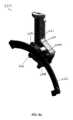
図2A及び図2Bには、ロボット外科用装置位置決めシステム40の一実施形態が示されている。システム40は、受動支持アーム42と、アーム42に回転可能に結合された肉眼的ロボット位置決め装置44と、を含む。更に、示されるように、この特定の例示的な実装形態では外科用装置46によって表される任意の既知のロボット装置46は、ロボット外科用装置46が開口部、オリフィス、切開部、又はポートを通して患者の対象の腔内に配設されるように、位置決め装置44に取り外し可能に結合することができる。この特定の実施形態では、図2Bに最良に示されるように、ロボット外科用装置46は、ポート48を通して配設される。特定の実施形態では、ポート48は、ジェルポート48である。 One embodiment of a robotic surgical
この実装形態-及び本明細書に開示又は想到される様々な他の実施形態-の肉眼的位置決め装置44は、3自由度(「DOF」)のロボット遠隔運動中心(RCM)機構である。RCMは、回転関節がそれを中心として回転する点であること、更に、RCM機構は、全ての運動学的関節が同じRCM点を通って移動する装置であることが理解される。本明細書の様々な肉眼的位置決め装置(ロボット位置決め装置44を含む)の場合、ロボット外科用装置46のエンドエフェクタを依然として望ましく操作できる間、機構の残部に対して相対運動しない点が存在するように、RCM点は、ロボット位置決め装置44の作業空間内にある。より具体的には、多くの実装形態では、RCMは、外科使用中に、切開部、ポート、又はオリフィスの近くに位置する。例えば、図2Bに最良に示される特定の実施形態では、RCM点50は、ポート48に位置決めされる。このように、ロボット外科用装置46が、依然として対象の手術部位(患者の腔内)に完全にアクセスすることを可能にしながら、この患者と装置との境界面には、患者に傷害を生じさせ得る相対運動が存在しない。 The
図2A~図2B、図3B、及び図9Bに最良に示されるように、外科用ロボット装置46は、接続クランプ52を介して、肉眼的位置決め装置44にドッキングすること、又は別様に取り外し可能に結合することができる。この特定の実施形態では、クランプ52は、クランプ52を陥凹領域54内に容易に配設することができるように、ロボット外科用装置44の外面の周りに陥凹領域54(例えば、クランプ溝)を有する装置44上の特定の場所において、ロボット位置決め装置44に結合可能である。例えば、図9Bに示されるように、同様のクランプ256の実施形態は、ラッチ機構257を有する。代替的に、任意の既知の結合特徴部又は機構を使用することができる。この実施形態では、外科用ロボット装置46は、肉眼的位置決め装置44とドッキングされると、クランプ52に対して移動又は回転しない。取り付け機構52は、ユーザが所望するときに容易かつ迅速に係合解除される。 As best shown in FIGS. 2A-2B, 3B, and 9B, surgical
上で論じたように、図2Bに最良に示されるように、ポート48は、様々な形態であり得る。一実施形態は、ジェルポートであり、これは、ジェル状の物質を含み、吹送を維持しながらロボットが移動することを可能にするようにロボットの外周を封止する。別のポートは、空気流を使用して患者吹送を維持する。他の実施形態は、隔膜、ダックビル、Oリング若しくは他のタイプの封止、又はポートなどの、様々なタイプのメカニカルシールを使用し得る。流体封止を維持することができる任意の既知のポートを使用することができる。 As discussed above, as best shown in FIG. 2B,
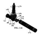
図3A及び図3Bに示される肉眼的位置決め装置60の別の実施形態によれば、位置決め装置60は、3つの関節、すなわち、ヨー(関節1)62と、ピッチ(関節2)64と、プランジ(関節3)66と、を有する。ヨー62及びピッチ64は、RCMを中心として回転し、プランジ66は、RCM68を通って移動する。この実施形態では、各関節は、完全に結合解除されて、独立して制御される。更に、特定の実施形態では、モータ及びモータコントローラ(図示せず)は、各関節62、64、66に共同配置される。加えて、各関節62、64、66は、逆駆動可能とすることができるが、必須ではない。 According to another embodiment of the
ヨー関節62は、肉眼的ロボット位置決め装置60の本体70、及びより具体的には、ヨー機構構造体72を起点とする。より具体的には、回転可能なヨー出力シャフト74は、ヨー機構構造体72から延在して、ヨー関節62を構成する。このように、出力シャフト74の回転は、ヨー関節62を中心としたヨー運動を生じさせる。ヨーアクチュエータ88は作動されて、例えば、ロボット位置決め装置60のヨー配向を調整して、ヨー機構構造体72及び本体70を矢印Aによって示されるように左又は右に調整し得る。すなわち、ヨーアクチュエータ88は、所望に応じて、出力シャフト74を回転させ、それによって、構造体72及び本体70をいずれかの方向に回転させるように作動することができる。追加的に、本体70の回転はまた、ピッチ機構76及びプランジ機構82も回転させる。 The yaw joint 62 originates from the
ピッチ関節64も同様に、装置60の本体70、より具体的には、ピッチ機構構造体76を起点とする。より具体的には、出力レール78は、(以下で詳細に説明するように)ピッチ機構構造体76に対する出力レール78の運動がピッチ関節64を生じさせるように、回転可能なベアリング80(例えば、溝付きの回転可能なベアリング)を介してピッチ機構構造体76に動作可能に結合される。いくつかの実施例では、回転可能なベアリング80は、出力レール78の縁部の対応するジオメトリと係合する。このように、ベアリング80に沿ってある方向又は他の方向へ移動する出力レール78の作動は、ピッチ関節64にピッチを生じさせる。図3Bに最良に示されるように、ピッチアクチュエータ90は、プランジ機構構造体82のピッチ配向を調整するように作動し得る。すなわち、ピッチアクチュエータ90は、所望に応じて、出力レール78を所望の方向に移動させて、構造体82を移動させるように作動することができる。 The pitch joint 64 likewise originates from the
プランジ関節66は、出力レール78に動作可能に結合されるプランジ機構構造体82を起点とする。より具体的には、拡張可能なレール84は、(以下で図3B及び図9A~図9Bの一実施例に従って最良に示されるように)回転可能なベアリング86を介してプランジ機構構造体82に動作可能に結合される。いくつかの実施例では、回転可能なベアリング86は、拡張可能なレール84の縁部の対応するジオメトリと係合する。このように、拡張可能なレール84の遠位方向の延在は、プランジ関節66においてプランジを生じさせる。プランジアクチュエータ92は、拡張可能なレール84の位置をプランジ関節に沿って調整するように作動され得る。すなわち、プランジアクチュエータ92は、所望に応じて、拡張可能なレール84を所望の方向に移動させて、そこに取り付けられた任意の装置を移動させるように作動することができる。したがって、ドッキングした場合、拡張可能なレール84の運動はまた、クランプ52及び装置46も移動させる。 Plunge joint 66 originates from a
図4A及び図4Bに最良に示されるように、装置位置決めシステム100の別の実装形態は、湾曲レール118によって少なくとも部分的に画定された環状ピッチ円弧の中心に位置するRCM102を有する。代替的に、RCM102は、肉眼的位置決め装置106に対して任意の既知の位置に配設することができる。ロボット外科用装置-装置104など-が、肉眼的ロボット位置決め装置106にドッキングされた(又は別様に結合された)ときに、RCM102は、示されるように、ロボット外科用装置104の細長い本体(又は管)108内に配設され、運動学的原点110とほぼ同一直線上である。図4Aはまた、ロボット外科用装置104に関連するロボット位置決め装置106の作業空間112も示す。肉眼的位置決め装置106は、エンドエフェクタ116が作業空間112内の任意の場所(例えば、トロイダル作業空間)内を移動することができるように、運動学的原点110を、したがってロボット外科用装置104を移動させるために使用することができる。図4Bに最良に示されるように、ピッチ及びプランジによって管理される作業空間112の断面は、環形セクタ114である。 As best shown in FIGS. 4A and 4B, another implementation of
図4Aに戻ると、ヨー関節(図3Aに関して上で詳細に論じた出力シャフト74の関節62など)は、回転関節であり、少なくとも165度のスイープ角にわたって関節動作することができる。図4Aの実施形態では、作業空間112は、360度の移動角を有する出力シャフト74(ヨー)の周りの回転を示し、肉眼的位置決め装置106が、特定の実施形態によれば、(配線の調整が許容する)いずれかの方向に回転し続けることができることを意味する。ピッチ関節(図3Aに関して上で詳細に論じたレール78によって生じる関節64など)は、出力ピッチレール118に沿った運動によってRCM102を中心とした回転を可能にする。ピッチの場合、特定の実装形態によれば、垂直から約20~70度のピッチ角度で50度の円弧を横断することができる。いくつかの代替の実施形態では、垂直から約20~60度のピッチ角度で40度の円弧を横断することができる。加えて、プランジ関節(図3Aに関して上で詳細に論じたレール84によって生じる関節66など)は、並進関節であり、様々な実施形態によれば、少なくとも100cmの全長を並進することができる。 Returning to FIG. 4A, the yaw joint (such as joint 62 of
図5に示されるロボット肉眼的位置決め装置120の実施形態では、各関節122(ヨー)、124(ピッチ)、及び126(プランジ)は、独立して移動することができ、又は任意の組み合わせかつ任意の速度で一緒に移動することができる。しばしば、ロボット外科用装置128は、装置128上のカメラ132の視野130のフレームに対して再位置決めされる。この実装形態では、カメラ132がロボット的に関節動作するので、その視野130は、必ずしもRCM134と同軸になり得ない。したがって、あるときには、関節122、124、及び126の組み合わせは、示される実施例のように、所望に応じて、ロボット外科用装置128をカメラフレーム130内で移動させるように関節動作しなければならない。 In the embodiment of the robotic
ピッチ124及びプランジ126関節は、特定の実施形態では、正確な絶対位置決め制御を有することができ、大部分の外科状況における肉眼的ロボット位置決め装置120の構成によって許容される全作業空間を関節動作することができる。絶対位置感知は、ピッチ124及びプランジ126段を駆動するために使用されるモータ(図示せず)上のエンコーダ(図示せず)によって達成できることが理解される。代替的に、駆動レール上のマーキングを読み取る視覚ベースのシステムを絶対位置感知に使用することができる。更なる代替案では、ピッチの絶対位置の感知は、一対の慣性測定ユニット(IMU)を使用して達成することができ、1つのIMUが、ヨー機構構造体136内のヨー関節122に対して垂直に装着され、第2のIMUが、プランジ機構構造体140内のプランジ関節126の並進軸に対して垂直に装着される。各IMUは、センサの法線ベクトルに対する重力加速度ベクトルの方向を測定するように構成することができる。次いで、2つのIMUの指示値の差を計算することによって、(例えば、リアルタイムで、又は遅延して)絶対ピッチ角が決定され得る。プランジ関節126の並進軸に沿った絶対位置感知のために、ストリップ142(例えば、線形磁気スケールノギスストリップ)が、プランジレール144上に位置し得るか、又は埋設され得る。場合によっては、このストリップの位置は、ストリップ142に近接してプランジ機構構造体140の内側に装着された一対の異方性磁気抵抗センサの使用を通じて決定することができる。代替的に、絶対位置制御を達成するために、任意の既知のセンサ又は機構を使用することができる。 The
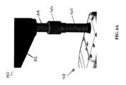
図6A及び図6Bは、支持アーム152の接続シャフト154に結合された(上記の出力シャフト74と同様の)出力シャフト160を含む、ヨー機構150の例示的な一実施形態を示す。図6Aは、接続シャフト154に結合された出力シャフト160の斜視図を示し、一方で、図6Bは、接続シャフト154に結合された出力シャフト160の断面図を示す。この特定の実装形態では、出力シャフト160及び接続シャフト154の結合及び結合解除は、一実施形態による、出力シャフト160において肉眼的位置決め装置168を支持アーム152に/から取り付ける/取り外すための、比較的迅速かつ簡単な方法である。 FIGS. 6A and 6B show an exemplary embodiment of
図6Bに示されるように、出力シャフト160は、雄型ダブテール特徴部162を有し、これは、ばね付勢のボール戻り止め158が出力シャフト160の中央穿設孔164と係合するまで、接続シャフト154の雌型ダブテール特徴部156内に摺動する。このボール戻り止め158は、雄型ダブテール特徴部162及び雌型ダブテール特徴部156の接続に予荷重を付与して、出力シャフト160を接続シャフト154と同軸に位置合わせし得る。接続を完了するために、スリーブ166は、出力シャフト160及び接続シャフト154の接続部上を摺動して下り、接続を固定して、予想外の結合解除を防止する。接続部は、装置の重量を支持して、出力シャフト160と接続シャフト154との間の回転運動を防止し、一方で、スリーブ166は、相対並進を防止する。代替的に、清掃及び殺菌などのために、肉眼的位置決め装置168とロボット支持アーム152とを容易にドッキング及びドッキング解除するために、任意の他の既知の迅速な接続機構(例えば、図19A及び図19Bに示される機構など)を使用することができる。 As shown in FIG. 6B, the
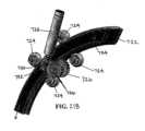
図7A~図7Dは、一実施形態による、(上で論じた関節62と同様の)ヨー関節180を示す。より具体的には、図7Aは、ヨー関節180が出力シャフト184を起点とするように構造体182から回転可能に延在する出力シャフト184を有する、ヨー機構構造体182を示す。一実施形態では、構造体182は、モータハウジング(又はセクション)216と、駆動列ハウジング(又はセクション)208と、を有することができる。代替的に、構造体182は、1つのセクション又はハウジングのみを有する。出力シャフト184は、ヨー機構構造体182によって回転されて、肉眼的位置決めロボット(図示せず)をロボット支持アーム(図示せず)に対して回転させることができる。 7A-7D show a yaw joint 180 (similar to joint 62 discussed above), according to one embodiment. More specifically, FIG. 7A shows a
一実施形態では、図7B~図7Dに最良に示されるように、構造体182は、モータ184を有し、モータ184は、シャフト184を回転させることができるように、一連の歯車を介して出力シャフト184に回転可能に結合される。構造体182のハウジングが示されない図7Bに最良に示されるように、この例示的な実装形態の歯車は、モータ186に回転可能に拘束され、かつ被駆動歯車190に回転可能に結合された駆動歯車188を含む。被駆動歯車190は、被駆動歯車190の回転が、ウォームねじ192の回転を、したがって、ウォームホイール194の回転を生じさせるように、ウォームねじ192に回転可能に拘束され、それがウォームホイール194にねじ込み可能に結合される。ウォームホイール194は、出力シャフト184に回転可能に拘束される。このように、モータ186の作動は、駆動歯車188の回転を生じさせ、それが被駆動歯車190を回転させ、それがウォームねじ192を回転させ、それがウォームホイール194を回転させ、それが出力シャフト184の回転を生じさせる。一実装形態では、歯車は、高速モータ出力を、必要とされる低速高トルクに変換する、全減速を提供することができる。代替的に、出力シャフト184の回転を生じさせるために、他の既知の歯車又は回転要素が使用され得る。 In one embodiment, as best shown in FIGS. 7B-7D, the
モータ及び駆動トレイン構成要素は、様々な既知の機構及び特徴部を介して構造体182内で支持及び位置決めすることができる。したがって、以下で論じる特定のベアリング、ワッシャ、スペーサ、及び他の構成要素は、例示的で、非限定的なものである。例えば、この実施形態では、出力シャフト184は、システムの重量を支持するためにフランジ付き又はキャップ付きとすることができる2つのベアリング196A、196B(例えば、対向する角度接触ベアリング)によって支持することができる。加えて、シャフトをベアリング196A、196Bに対して軸方向に拘束する保持リング(図示せず)を提供することができる。トルクは、例えば、キー及びキー溝(図示せず)によって、ウォームホイール192からホイール194、出力シャフト184に伝達することができる。駆動歯車188/被駆動歯車190段は、モータ186を軸方向負荷から保護することができ、一方で、中間平行シャフト200は、角度接触ベアリング198A、198Bによるウォームへの軸方向スラストに対して支持される。予荷重は、示されるように、円板ばね206によって達成することができるが、他の方法は、軸方向波状部又はばね座金(図示せず)の使用を含む。精密スペーサ202は、全てのベアリング及び歯車をシャフト上に位置付けるために使用することができる。 Motors and drive train components may be supported and positioned within
一実施形態では、歯車トレインは、駆動トレインハウジング208内に配設される。ウォームねじベアリングキャップ210は、ウォームねじ192、角度接触ベアリング198、スペーサ202、及び円板ばね206をハウジング208内に保持する。図7C及び図7Dに最良に示されるように、本体182は、ベースプレート212を有することができ、一方で、駆動トレインハウジング208は、トッププレート214を有することができる。更に、モータ186、モータコントローラ(図示せず)、及びケーブル(図示せず)は、一緒にモータハウジング216内に収容することができる。更に、ヨー機構構造体(又は「ハウジング」)182は、より良好にトルクを伝達して装置全体を移動させるために、一対の位置決めピン(図示せず)及び低プロファイルの段付きねじ(図示せず)などを使用して、ピッチ機構構造体(図示せず)に確実に締結することができる。 In one embodiment, the gear train is disposed within
特定のヨー機構構造体182は、所望のヨー運動を生じさせるために使用することができる適切な内部構成要素を有する適切な構造体の単なる一例である。同じ運動を達成するために、任意の他の既知の構造体及び既知の内部機構を本明細書に組み込むことができる。 The particular
図8A~図8Cは、一実施形態による、(上で論じた関節64と同様の)ピッチ機構220を示す。機構220は、本体221と、本体221に対する出力レール222の運動からピッチが生じるように本体221に摺動可能に結合された、湾曲した出力レール222と、を有する。出力レール222は、一実施形態によれば、円弧のセグメントを構成する細長い湾曲した構造体222である。更に、出力レール222は、レール222の運動がRCM(図示せず)を中心とするプランジハウジング(及び任意の取り付けられたロボット外科用装置)の回転を生じさせるように、以下で説明するようにピッチ機構本体221に摺動可能に結合され、更に、(本明細書の他の場所で論じられるように)レール222の一方の端部においてプランジハウジングに固定的に結合される。レール222は、バー又は任意の他の細長い湾曲した構造体とすることができる。 8A-8C show a pitch mechanism 220 (similar to joint 64 discussed above), according to one embodiment.
一実施形態では、出力レール222は、回転可能なベアリング224及び駆動ローラ226を介してピッチ機構本体221に結合される。示される特定の実装形態では、レール222が各ベアリング224及びローラ226の各々と接触し、また、駆動ローラ226によってベアリング224に対して並進移動するように付勢することができるように、レール222の両側に位置決めされる3つのベアリング224(例えば、溝付きの回転可能なベアリング)及び駆動ローラ226(例えば、溝付き摩擦駆動ローラ)が存在する。更に、以下で追加的に詳細に説明されるように、ベアリング224A、224Bの2つは、互いに対向してピッチレール222の上側及び下側に位置決めされる。追加的に、第3のベアリング224Cは、第3のベアリング224Cが駆動ローラ226に対向するレール222の上側に位置決めされるように、本体221に張力付与可能に結合された板ばね234の端部に装着される。板ばね234は、レール222が設置されたときに偏向し得、これにより、板ばね234の結果として、垂直な予荷重力が、レール222を通してローラ226に印加され得る。この予荷重力によるローラ226とピッチレール222との間の摩擦は、滑ることなくローラ226をピッチレール222(例えば、レール226の縁部)と係合させる。代替的に、レール226又は駆動ローラ226に十分な力を印加して、いかなる滑りも伴わずにローラ226がレール222に係合することを確実にするために、任意の張力付与可能な構成要素又は他の機構を使用することができる。更に、ベアリング224A~224C及び駆動ローラ226の特定の構成の代わりに、所望のピッチ運動を達成するために、本体221に対するレール222の運動を可能にすることができる、任意の1つ以上の既知の構成要素を本明細書に組み込むことができる。 In one embodiment,
図8Bに最良に示されるように(本体221のハウジングは示さず)、駆動ローラ226は、一連の回転要素を介して駆動ローラ226に、したがって、出力レール222に回転可能に結合されるモータ228によって作動される。この特定の実施形態に関して説明される特定の回転要素は、例示的なものであり、任意の既知の回転要素又は他の機構、及びその構成を使用できることが理解される。この例示的な実装形態の回転要素は、モータ228に回転可能に拘束され、かつウォームホイール232にねじ込み可能/回転可能に結合されるウォームねじ230である、駆動歯車230を含む。代替的に、駆動歯車230は、任意のタイプのホイール232又は同様の構成要素に結合された任意のタイプの歯車又は構成要素とすることができる。上で説明したように、ウォームホイール232は、ローラ226に回転可能に拘束され、それがピッチレール222に回転可能に結合される。したがって、モータ228の作動は、駆動歯車230の回転を生じさせ、それがウォームホイール232の回転を生じさせ、それがローラ226の回転を、したがって、レール222の並進を生じさせる。一実装形態では、歯車は、高速モータ出力を、必要とされる低速高トルクに変換する、全減速を提供することができる。 As best shown in FIG. 8B (the housing of
一実施形態では、ウォームホイール232及び回転可能なローラ226を含むシャフトは、ウォームホイール232の両側にあるシャフトの対向端部上の2つのベアリング236によって支持することができる。代替的に、支持構成要素は、駆動トレイン内で一組の歯車を支持するための任意の既知の構成要素又は機構とすることができる。シャフトは、本体221内に配設され得る。更に、一実施形態では、モータ228、歯車トレイン、モータコントローラ(図示せず)、及びケーブル(図示せず)もまた、一緒に本体221に収容される。更に、以下で詳細に論じるように、図8Cに最良に示されるように、出力レール222は、位置合わせピン238及びねじ240によってプランジハウジングに締結される。代替的に、出力レール222は、任意の既知の結合機構又は特徴部を介してプランジハウジングに結合することができる。 In one embodiment, the shaft containing
図9A~図9Bは、一実施形態による、(上で論じた関節66と同様の)プランジ装置又は機構250を示す。より具体的には、図9Aは、プランジ機構構造体(又は「本体」、又は「ハウジング」)252を示し、構造体252は、構造体252がレール254を作動させて移動させる結果として、構造体252に対する出力レール254の並進運動からプランジが生じるように、移動可能に結合された出力レール254を有する。出力レール254は、レール254の運動がクランプ256内に配設された任意のロボット装置(図示せず)の運動を生じさせ、それによって、手術部位においてロボット装置をポート(又は切開部、又は開口部)の内外へ並進させるように、実質的に直線状の細長い構造体254であり、これは、以下で説明するように、プランジ機構ハウジング252に移動可能に結合され、更に、レール254の一方の端部においてロボット取り付けクランプ256に固定的に結合される。レール254は、バー又は任意の他の細長い構造体とすることができる。 9A-9B show a plunge device or mechanism 250 (similar to joint 66 discussed above), according to one embodiment. More specifically, FIG. 9A shows a plunge mechanism structure (or “body,” or “housing”) 252 that is actuated to move
図9Bに最良に示される一実施形態(ハウジング本体252は示さず)では、出力レール254は、回転可能なベアリング258A、258B、258C(例えば、3つの溝付きベアリング)及び駆動ローラ260(例えば、溝付き摩擦駆動ローラ)を介して、プランジ機構構造体252に結合される。示される特定の実装形態では、ベアリング258A~Cは、レール254が、各ベアリング258A~Cと接触し、また、ベアリング258A~Cに対して並進移動することができるように、レール254の両側に位置決めされる。ベアリング258A、258Bの2つは、プランジ機構構造体252の一方の端部においてレール254の両側に互いに対向して位置決めされる。第3のベアリング258Cは、プランジ機構構造体252の第2の端部においてローラ260に対向して本体221に張力付与可能に結合された板ばね268に結合される。場合によっては、プランジレール254が設置されたときに板ばね268の偏向が生じ得、これは、板ばね268の結果として、レール254を通してローラ260に対して垂直に予荷重力を印加し得る。予荷重力及び駆動ローラ260とプランジレール254との間に生じる摩擦は、駆動ローラ260が、滑ることなくプランジレール254(例えば、レール254の縁部)と係合することを可能にすることができる。代替的に、レール254又は駆動ローラ260に十分な力を印加して、いかなる滑りも伴わずにローラ260がレール254に係合することを確実にするために、任意の張力付与可能な構成要素又は他の機構を使用することができる。更に、ベアリング258A~258C及び駆動ローラ260の特定の構成の代わりに、所望のプランジ運動を達成するために、本体252に対するレール254の運動を可能にすることができる、任意の1つ以上の既知の構成要素を本明細書に組み込むことができる。 9B (
図9Bに最良に示されるように、一実装形態によれば、駆動ローラ260は、一連の回転要素を介して駆動ローラ260に、したがって、出力レール254に回転可能に結合されるモータ262によって作動される。この特定の実施形態に関して説明される特定の回転要素は、例示的なものであり、任意の既知の回転要素又は他の機構、及びその構成を使用できることが理解される。この例示的な実装形態の回転要素は、(例えば、モータ262の出力シャフトにおいて)モータ262に回転可能に拘束され、かつウォームホイール266にねじ込み可能/回転可能に結合されるウォームねじ264である、駆動歯車264を含む。ウォームホイール266は、回転可能にローラ260に拘束され、それが摩擦によってプランジレール254の縁部に結合される。したがって、モータ262の作動は、駆動歯車264の回転を生じさせ、それがウォームホイール266の回転を生じさせ、それがローラ260の回転を、したがって、レール254の並進を生じさせる。代替的に、レール254の作動もまた、平歯車を使用して、プランジレール254に取り付けられたラックと係合することで達成することができる。特定の実装形態では、歯車は、高速モータ出力を、必要とされる低速高トルクに変換する、全減速を提供することができる。 As best shown in FIG. 9B, according to one implementation, the drive roller 260 is actuated by a
一実施形態によれば、ウォームホイール266及びローラ260を含むシャフトは、ウォームホイール266の両側にあるシャフトの対向端部上の2つのベアリング270によって支持することができる。代替的に、支持構成要素は、駆動トレイン内で一組の歯車を支持するための任意の既知の構成要素又は機構とすることができる。シャフトは、プランジハウジング252内に配設され得る。更に、一実施形態では、モータ262、歯車トレイン、モータコントローラ(図示せず)、及びケーブル(図示せず)もまた、一緒にプランジハウジング252に収容される。 According to one embodiment, the shaft containing
これらの3つのヨー関節、ピッチ関節、及びプランジ関節の代替の変形例は、摩擦駆動ローラ以外の任意の既知の機構を使用できることが理解される。例えば、関節の各々は、歯車を使用すること、又はモータによって直接駆動することができる。更なる代替案では、レールに沿った運動は、歯車を使用しない場合があり、代わりに、単に支持ローラのうちの1つを駆動して、レールに沿った運動を生じさせ得る。加えて、所望の出力運動を生じさせるために、他の既知の設計では、油圧駆動、空気圧駆動、又はケーブル駆動を使用することができる。 It is understood that alternate variations of these three yaw, pitch and plunge joints can use any known mechanism other than friction driven rollers. For example, each of the joints can be driven using gears or directly by a motor. In a further alternative, the motion along the rail may not use gears and instead may simply drive one of the support rollers to produce motion along the rail. Additionally, other known designs may use hydraulic, pneumatic, or cable drives to produce the desired output motion.
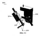
図10は、ロボット支持アーム280の一実施形態を示す。この実装形態では、支持アーム280は、垂直(又は「ベースカラム」)ロッド282と、第1の回転可能な関節288においてロッド282に回転可能に結合された第1の細長いアーム284と、第2の回転可能な関節290において第1のアーム284に回転可能に結合された第2の細長いアーム286と、を有する。2つの回転軸288A、290Aが垂直方向に平行であるように、第1の関節288が第1の回転軸288Aを有し、第2の関節290が第2の回転軸290Aを有する。これは、患者に対して肉眼的位置決めロボット装置292を平面(X/Y方向)位置決めすることを可能にする。加えて、(上で論じたヨー軸62と同様の)肉眼的位置決めロボット装置292のヨー軸294もまた、他の2つの回転軸288A、290Aに垂直方向に平行である。 FIG. 10 shows one embodiment of a
支持アーム280の垂直位置決め(Z方向)は、クランプ296を使用して、ベッドレール(図示せず)において調整することができる。垂直ロッド282は、クランプがベッドレールに取り付けられる前に、又はその後に、クランプ296と結合することができる。ロッド282の垂直配置が選択されると、肉眼的位置決めロボット装置292を支持アーム280にドッキングすること、又は別様に取り付けることができる。次いで、ロボット外科用装置(図示せず)の挿入プロセス全体を含む、必要に応じてアーム280を水平に位置決めすることができる。ロボット外科用装置(図示せず)の最終位置が選択されると、肉眼的位置決めロボット装置292は、ロボット外科用装置(図示せず)とドッキングされる。典型的には、これは、ほぼポート/切開部/開口部にRCMを位置決めすることによって達成される。この時点で、支持アーム280は、関節ロック298、300を使用して、所定の位置に係止することができる。 The vertical positioning (Z-direction) of
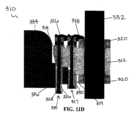
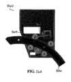
一実施形態では、(例えば、クランプ296と同様の)ベッドレールクランプ310が図11A~図11Dに示されている。ベッドに装着された、片持ちビームとして作用する支持アームを使用する場合、緩い又は柔軟なベッドレールは、大きい偏向を生じさせる可能性がある。これを防止するために、(アーム280などの)ロボット支持アームを、ベッドレールクランプ310を使用して、標準外科用ベッドレールに締結することができる。クランプ310は、クランプ本体312を有し、2つのクランプシャフトカラー320がそれに結合され、本体312の各端部に1つのカラー320を有し、よって、以下で詳細に説明するように、クランプ体312は、(アーム280と同様の)支持アームのロッド332を受容することができ、カラー320は、そこにロッド332を固定することができる。更に、図11Dに最良に示されるように、クランプ310は、クランプ310に取り付けられた2つの取り付け機構315、317を介して、ベッドレール336に固定可能に取り付けることができる。第1の又は外側取り付け機構315は、第1のハンドル316によって作動され、かつ第1のくさび314及び第2のくさび326に動作可能に結合される、作動可能なボルト324を有する。第1の取り付け機構315は、レール336とベッド334との間に配設することができる。第2の又は内側取り付け機構317は、第2のハンドル318によって作動され、かつクランプジョー330に動作可能に結合される、作動可能なボルト319を有する。第2の取り付け機構317は、レール336に隣接して、(第1の取り付け機構315の反対側の)レールの外面に配設される。 In one embodiment, a bedrail clamp 310 (eg, similar to clamp 296) is shown in FIGS. 11A-11D. When using bed-mounted support arms that act as cantilevered beams, loose or flexible bed rails can cause large deflections. To prevent this, a robotic support arm (such as arm 280 ) can be clamped to a standard surgical bedrail using
使用時に、ベッドレールクランプ310をベッドレール336に固定するには、第1の取り付け機構315がレール336とベッド334との間に位置決めされ、一方で、第2の取り付け機構317がレール336の外面に隣接して位置決めされるように、ベッドレールクランプ310がレール336に対して位置決めされる。所望の場所に着座させた時点で、ハンドル316(例えば、拡大クランプカムハンドル)を(図11B及び図11Dに最良に示される)下方の係止位置へ付勢して、作動可能なボルト324を上方へ付勢し、それによって、底部くさび326を上方へ付勢させることができ、よって、底部くさび326の角度付き面が頂部くさび314の角度付き面と係合し、よって、くさび326、314の両方が横方向に付勢される。このように、底部くさび326は、ベッド334に対して付勢され、一方で、頂部くさび314は、レール336の内面に対して付勢され、それによって、レール336及びベッド334にクランプ310を張力付与可能に固定する。ハンドル316が係止位置になった後、ハンドル318(例えば、レールクランプカムハンドル)を(図11B及び図11Dに最良に示される)下方の係止位置へ付勢して、作動可能なボルト319を上方へ付勢し、それによって、クランプジョー330を上方へ移動させてレール336の底面と接触させ、それによって、クランプ310を垂直ロッド332に印加される力によって生じるずれから固定する。 In use, to secure
ベッドレールクランプ310がベッド334に確実に装着された時点で、ベッドレール装着本体312に取り付けられたクランプシャフトカラー320を通して、ロッド332を挿入することができる。図11Cに示されるように、カラムクランプカムハンドル322は、係止位置に係合されて、ロッド332の周りにカラー320を締め付けることによって支持カラムを所望の高さに固定する。これらのカラムクランプカムハンドル322は、係合解除及び再係合して、ユーザが、所望に応じて支持アームカラム332を手動で上昇及び下降させることを可能にすることができる。親ねじ機構を介してカラムの高さを調整するためのハンドクランク又はモータの使用などの、支持アームカラムを上昇及び下降させるための代替の方法を使用できることが理解される。 Once the
代替の一実施形態によれば、本明細書の肉眼的位置決めロボット装置の実施形態のいずれかは、追加的な特徴部-レーザ支援位置決め-を有することができる。より具体的には、図12に示されるように、1つの肉眼的位置決めロボット装置340の実施形態は、3つのラインレーザ342、344、352を有し、1つのレーザ342がプランジハウジング346に配設され、1つのレーザ344がピッチハウジング348に配設され、1つのレーザ352がヨーハウジング354に配設される。レーザ352は、ヨー軸356と同軸に装着され得る。レーザ342、344、352は、各レーザ342、344、352からのレーザ光をRCM350において交差させるように位置決め及び照準される。したがって、一実施形態では、レーザ342、344、352は、肉眼的位置決めロボット装置340を簡単にドッキング及び位置決めするのを補助することができ、レーザによって示されるRCM350は、ユーザによって患者の切開部/ポート/開口部に容易に位置付けることができる。代替の数のレーザ(例えば、図25に示される2つのレーザなど)が使用され得ることが理解される。本明細書に開示又は想到される様々なレーザの実施形態は、本明細書に開示される任意の肉眼的位置決め装置の実施形態に組み込むことができる。 According to an alternative embodiment, any of the macroscopic positioning robotic device embodiments herein can have an additional feature--laser assisted positioning. More specifically, as shown in FIG. 12, one macroscopic positioning
図13A及び図13Bに示されるように、また、図8A及び図9Bに関して上で論じたように、本明細書の肉眼的位置決め装置の実施形態の様々な実装形態はまた、ベアリングとレールとの接触を確実にするためにピッチハウジング及び/又はプランジハウジングのうちの少なくとも1つのベアリングに印加される張力付与力を提供する、張力付与機構も含むことができる。より具体的には、図13Aに示されるように、ピッチハウジング360の例示的な一実施形態は、ベアリング364がレール366と接触するように付勢する力をベアリング364に印加する、板ばね362を有する。 As shown in FIGS. 13A and 13B, and as discussed above with respect to FIGS. 8A and 9B, various implementations of the macroscopic positioning device embodiments herein also incorporate the A tensioning mechanism may also be included that provides a tensioning force applied to the bearing of at least one of the pitch housing and/or the plunge housing to ensure contact. More specifically, as shown in FIG. 13A, one exemplary embodiment of
板ばね362は、手動で張力付与解除して、又は別様にレール366から離れるように付勢して、ベアリング364とレール366との接触を除去することができる。これは、レール366をピッチハウジング360から係合解除することを可能にする。追加的又は代替的に、ピッチレール376は、ハードストップ又は「突起」368を含む。ピッチレール366の端部に位置するトグル可能な突起368は、係合解除して、レール366をピッチハウジング360から係合解除することを可能にすることができる。次いで、清掃及び殺菌の必要性に応じて、各副構成要素を容易に分解する。 Leaf spring 362 may be manually untensioned or otherwise biased away from rail 366 to remove contact between
同様に、図13Bに示されるように、プランジハウジング370の例示的な一実施形態は、ベアリング374がレール376と接触するように付勢する力をベアリング374に印加する、板ばね372を有する。板ばね372は、手動で張力付与解除して、又は別様にレール376から離れるように付勢して、ベアリング374とレール376との接触を除去することができる。これは、レール376をピッチハウジング370から係合解除することを可能にする。追加的又は代替的に、プランジレール376は、ハードストップ又は「突起」378を含む。トグル可能な突起378は、係合解除して、プランジレール376をピッチハウジング370から係合解除することを可能にすることができる。次いで、清掃及び殺菌の必要性に応じて、各副構成要素を容易に分解する。板ばね362、372の代わりに任意の既知の張力付与機構を使用できること、及び突起368、378の代わりに任意の既知のトグル可能な機構を使用できることが理解される。 Similarly, as shown in FIG. 13B, one exemplary embodiment of
更なる代替の実施形態では、本明細書に開示又は想到される任意の肉眼的位置決めロボット装置は、ボタン(例えば、アクチュエータ88、90、92)、ジョイスティック(図示せず)、タブレット、又は任意の他の既知のインターフェースなどの、各関節を独立して駆動するためのローカルインターフェースを使用して、ベッド横で制御することができる。ユーザは、各関節を個々に、又はインターフェースによって同時にジョグすることができる。肉眼的位置決めロボット装置は、ロボット外科用装置が挿入されている間、脇によけておき、次いで、必要なときにこの機能とドッキングするために容易に導入することができる。インターフェースは、駆動方向に対応するボタン又はジョイスティックの関節動作方向を有する、直観的なものとすることができる。これを達成するために、ユーザインターフェースは、各関節に局在化させることができ、又は中央に位置付けることができる。ロボットを摘出する場合、ロボット外科用装置をドッキング解除することができ、肉眼的位置決めロボット装置を邪魔にならない所へジョグすることができる。 In further alternative embodiments, any gross positioning robotic device disclosed or contemplated herein may include buttons (e.g., actuators 88, 90, 92), joysticks (not shown), tablets, or any It can be controlled at the bedside using a local interface to drive each joint independently, such as other known interfaces. The user can jog each joint individually or simultaneously through the interface. The gross positioning robotic device can be set aside while the robotic surgical device is inserted and then easily introduced to dock with this function when needed. The interface can be intuitive, with button or joystick articulation directions corresponding to drive directions. To accomplish this, the user interface can be localized at each joint or centrally located. When extracting the robot, the robotic surgical device can be undocked and the gross positioning robotic device can be jogged out of the way.
図14A及び図14Bは、本明細書に開示又は想到される任意の肉眼的位置決めロボット装置の別の代替の特徴部、すなわち、巻き取られたケーブル380、を示す。この実施形態では、ケーブル380は、示されるように、ピッチハウジング382をプランジハウジング384に結合する。ケーブル380は、ピッチ関節がピッチされたときに自然に収縮及び伸長することによって、ケーブルが絡み合うことなくあらゆるピッチ角を可能にするために、コイル状である。代替の設計では、スリップリング又は関節カプセルを任意の又は全ての関節に使用することができる。これらの設計は、連続した、又は非常に広い範囲の運動を有することができる。 14A and 14B illustrate another alternative feature of any gross positioning robotic device disclosed or contemplated herein, namely coiled
図15A及び図15Bは、本明細書に開示又は想到される任意の肉眼的位置決めロボット装置上の任意のレールの別の代替の特徴部、すなわち、トグル可能なハードストップ又は「突起」402を示す。示されるように、ハードストップ400は、ピッチ出力レール404上に位置決めされる。トグル可能なハードストップ402は、ピッチレール404の端部に位置し、また、係合解除して、レール404をピッチハウジングから係合解除することを可能にすることができる。図15Aは、レール404をピッチハウジングから係合解除することができないように係合位置にあるハードストップ402を示す。図15Bは、図15Aからトグルされたハードストップ402を示し、ハードストップ402は、レール404をピッチハウジングから係合解除することができるように係合解除位置にある。ハードストップはまた、図13Aにおいて上で示されるように、プランジ出力レール上に位置決めできることが理解される。 15A and 15B illustrate another alternative feature of any rail on any macroscopic positioning robotic device disclosed or contemplated herein: a toggleable hard stop or "bump" 402. . As shown,
図16には、ロボット外科用装置位置決めシステム540の別の実施形態が示されている。図16~図23に開示される様々な実施形態は、図2A~図15Bにおいて上で開示又は想到した装置の実装形態と実質的に同様であり、本明細書で明示的に述べられる場合を除いて、実質的に同様の構成要素、特徴部、及び機能を有することが理解される。 Another embodiment of a robotic surgical device positioning system 540 is shown in FIG. The various embodiments disclosed in FIGS. 16-23 are substantially similar to the device implementations disclosed or contemplated above in FIGS. 2A-15B, except where explicitly stated herein. are understood to have substantially similar components, features, and functions, except for the
図16のシステム540は、受動支持アーム542と、アーム542に回転可能に結合された肉眼的位置決めロボット装置544と、を含む。更に、この特定の例示的な実装形態では、示されるように、装置546によって表される任意の既知のロボット装置546は、装置546が開口部、オリフィス、切開部、又はポートを通して患者の対象の腔に配設されるように、装置544に取り外し可能に結合することができる。 System 540 of FIG. 16 includes a
図17A及び図17Bに示される肉眼的位置決めロボット装置560の別の実施形態によれば、装置560は、3つの関節、すなわち、ヨー(関節1)562と、ピッチ(関節2)564と、プランジ(関節3)566と、を有する。ヨー562及びピッチ564は、RCMを中心として回転し、プランジ566は、RCM568を通って移動する。この実施形態では、各関節は、完全に結合解除されて、独立して制御される。更に、特定の実施形態では、モータ及びモータコントローラ(図示せず)は、各関節562、564、566に共同配置される。加えて、各関節562、564、566は、逆駆動可能とすることができるが、必須ではない。 According to another embodiment of a gross positioning robotic device 560 shown in FIGS. 17A and 17B, device 560 has three joints: yaw (joint 1) 562, pitch (joint 2) 564, and plunge. (Joint 3) 566 and . Yaw 562 and pitch 564 rotate about RCM and plunge 566 travels through RCM 568 . In this embodiment, each joint is fully decoupled and independently controlled. Additionally, in certain embodiments, a motor and motor controller (not shown) are co-located at each joint 562 , 564 , 566 . Additionally, each joint 562, 564, 566 may, but need not, be back-drivable.
ヨー関節562は、肉眼的ロボット位置決め装置560の本体570、より具体的には、ヨー機構構造体572を起点とする。より具体的には、回転可能なヨー出力シャフト574は、ヨー機構構造体572から延在して、ヨー関節562を構成する。このように、出力シャフト574の回転は、ヨー関節562においてヨーを生じさせる。 The yaw joint 562 originates from the body 570 of the gross robot positioning device 560 , more specifically the yaw mechanism structure 572 . More specifically, a rotatable yaw output shaft 574 extends from yaw mechanism structure 572 to define yaw joint 562 . Thus, rotation of output shaft 574 causes yaw at yaw joint 562 .
ピッチ関節564も同様に、装置560の本体570、より具体的には、ピッチ機構構造体576を起点とする。より具体的には、出力レール578は、(以下で詳細に説明するように)ピッチ機構構造体576に対する出力レール578の運動がピッチ関節564を生じさせるように、回転可能なベアリング580を介してピッチ機構構造体576に動作可能に結合される。このように、出力レール578の作動は、ピッチ関節564にピッチを生じさせる。 Pitch joint 564 likewise originates from body 570 of device 560 and, more specifically, from pitch mechanism structure 576 . More specifically, output rail 578 is coupled via rotatable bearing 580 such that movement of output rail 578 relative to pitch mechanism structure 576 produces pitch joint 564 (as described in detail below). It is operably coupled to pitch mechanism structure 576 . Actuation of output rail 578 thus causes pitch in pitch joint 564 .
プランジ関節566は、出力レール578に動作可能に結合されるプランジ機構構造体582を起点とする。より具体的には、拡張可能なレール584は、(図22A及び図22Bの一実施例に従って最良に示されるように)回転可能なベアリング586を介してプランジ機構構造体582に動作可能に結合される。このように、拡張可能なレール584の延在は、プランジ関節566においてプランジを生じさせる。 Plunge joint 566 originates from a plunge mechanism structure 582 that is operably coupled to output rail 578 . More specifically, expandable rails 584 are operably coupled to plunge mechanism structure 582 via rotatable bearings 586 (as best shown according to one embodiment in FIGS. 22A and 22B). be. Thus, extension of expandable rail 584 causes a plunge at plunge joint 566 .
図18A及び図18Bに最良に示されるように、装置位置決めシステム600の別の実装形態は、円弧状レール614の中心に位置するRCM602を有する。代替的に、RCM602は、肉眼的位置決め装置に対して任意の既知の位置に配設することができる。ロボット外科用装置-装置604など-が、肉眼的ロボット位置決め装置606にドッキングされた(又は別様に結合された)ときに、RCM602は、ロボット外科用装置604の細長い本体(又は管)608内に配設され、その運動学的原点610とほぼ同一直線上である。図18Aはまた、ロボット外科用装置604に関連する肉眼的位置決め装置606の作業空間612も示す。ロボット装置604の運動学的原点610が示されている。肉眼的位置決め装置606は、運動学的原点610をトロイダル作業空間612内の任意の場所へ移動させるために使用することができる。図18Bに最良に示されるように、ピッチ及びプランジによって管理される作業空間612の断面は、環形セクタ616である。 As best shown in FIGS. 18A and 18B, another implementation of
図18Aに戻ると、ヨー関節(図17Aに関して上で詳細に論じた関節562など)は、回転関節であり、少なくとも165度のスイープ角にわたって関節動作することができる。図18Aの実施形態では、作業空間612は、360度の移動角を有するヨーを示し、(配線の調整が許容する)いずれかの方向に回転し続けることができることを意味する。ピッチ関節(図17Aに関して上で詳細に論じた関節564など)は、出力レール614に沿った運動によってRCM602を中心とした回転を可能にする。ピッチの場合、特定の実装形態によれば、垂直から約20~60度のピッチ角度で40度の円弧を横断することができる。加えて、プランジ関節(図17Aに関して上で詳細に論じた関節566など)は、並進関節であり、様々な実施形態によれば、少なくとも100cmの全長を並進することができる。 Returning to FIG. 18A, yaw joints (such as joint 562 discussed in detail above with respect to FIG. 17A) are rotational joints and can articulate through a sweep angle of at least 165 degrees. In the embodiment of FIG. 18A, workspace 612 exhibits yaw with a 360 degree travel angle, meaning it can continue to rotate in either direction (wiring alignment allows). A pitch joint (such as joint 564 discussed in detail above with respect to FIG. 17A) allows rotation about RCM 602 by movement along output rail 614 . For pitch, a 40 degree arc may be traversed at a pitch angle of about 20-60 degrees from vertical, according to certain implementations. Additionally, plunge joints (such as joint 566 discussed in detail above with respect to FIG. 17A) are translating joints and can translate a total length of at least 100 cm, according to various embodiments.
図19A及び図19Bは、ヨー関節の出力シャフト640の例示的な一実施形態を示す。図19Aは、シャフト640の斜視図を示し、一方で、図19Bは、分解断面図を示す。図19Aに最良に示されるように、出力シャフト640は、ロボット支持アーム642と結合される。この特定の実装形態では、出力シャフト640は、ねじ山付きDシャフト640である。シャフト640の上部セクション644は、ねじ山648が画定された雌型接続開口部646を有し、ねじ山648は、ねじ山654が画定された下部セクション652の雄型接続突起650と結合可能である。結合されたねじ山648、654は、装置の重量を支持する。シャフト結合具656は、シャフト640の周りに配設され、また、係止止めねじ658A、658Bを有し、これらは、シャフト644の2つのセクション644、652のねじを緩めることなくトルクを伝達することを可能にする。代替的に、清掃及び殺菌などのために、肉眼的位置決めロボット装置660とロボット支持アーム642とを容易にドッキング及びドッキング解除するために、他の既知の迅速な接続機構を使用することができる。 19A and 19B illustrate an exemplary embodiment of a yaw
図20A~図20Dは、一実施形態による、(上で論じた関節562などの)ヨー関節670の内部機構を示す。より具体的には、図20Aは、ヨー関節670が出力シャフト674を起点とするように構造体672から回転可能に延在する出力シャフト674を有する、ヨー機構構造体672を示す。出力シャフト674は、肉眼的位置決めロボット(図示せず)をロボット支持アーム(図示せず)に対して回転させるように回転する。 Figures 20A-20D illustrate the inner workings of a yaw joint 670 (such as the joint 562 discussed above), according to one embodiment. More specifically, FIG. 20A shows a yaw mechanism structure 672 having an
一実施形態では、図20B~図20Dに最良に示されるように、出力シャフト674は、一連の回転要素を介して出力シャフト674に回転可能に結合されるモータ676によって作動される。歯車は、モータ676に回転可能に拘束され、かつ被駆動歯車680に回転可能に結合された駆動歯車678を含む。被駆動歯車680は、被駆動歯車680の回転が、ウォームねじ682の回転を、したがって、ウォームホイール684の回転を生じさせるように、ウォームねじ682に回転可能に拘束され、それがウォームホイール684にねじ込み可能に結合される。一実装形態では、歯車は、高速モータ出力を、必要とされる低速高トルクに変換する、5000:1の全減速を提供する。出力シャフト674は、システムの重量を支持するためにフランジ付き又はキャップ付きとすることができる2つのベアリング686、688によって支持される。加えて、シャフトをベアリング686、688に対して軸方向に拘束する保持リング690を提供することができる。トルクは、キー及びキー溝692によって、ウォームホイール682、684から出力シャフト674に伝達される。駆動歯車678/被駆動歯車680段は、モータ出力シャフト694を軸方向負荷から保護し、一方で、中間平行シャフト696は、予荷重を付与した角度接触ベアリング698、700によるウォームへの軸方向スラストに対して支持される。予荷重は、示されるように、軸方向波形ばね702によって達成することができるが、他の方法は、ばね座金又は円板ばね(図示せず)の使用を含む。スペーサ(図示せず)は、全てのベアリング及び歯車シャフト上に位置付けるために使用することができる。一実施形態では、歯車トレインは、モータブロック704内に配設される。組み立てられたモータブロック704、モータコントローラ(図示せず)、及びケーブル(図示せず)は、一緒に収容することができる。更に、ヨー機構構造体(又は「ハウジング」)672は、より良好にトルクを伝達して装置全体を移動させるために、段付きボルトなどを使用して、ピッチ機構構造体(図示せず)に確実に締結することができる。 In one embodiment, as best shown in Figures 20B-20D, the
図21A~図21Cは、一実施形態による、(上で論じた関節564などの)ピッチ関節の内部機構を示す。より具体的には、図21Aは、ピッチ機構構造体(又は「ハウジング」)720を示し、構造体720は、構造体720に対する出力レール722の運動からピッチが生じるように、構造体720に摺動可能に結合された出力レール722を有する。出力レール722は、一実施形態によれば、円弧のセグメントを構成する細長い湾曲した構造体722である。更に、出力レール722は、レール722の運動がRCM(図示せず)を中心とするプランジハウジング(及び任意の取り付けられたロボット外科用装置)の回転を生じさせるように、以下で説明するようにピッチ機構ハウジング720に摺動可能に結合され、更に、レール722の一方の端部においてプランジハウジング(図示せず)に固定的に結合される。 Figures 21A-21C illustrate the inner workings of a pitch joint (such as joint 564 discussed above), according to one embodiment. More specifically, FIG. 21A shows a pitch mechanism structure (or “housing”) 720 that slides on
一実施形態では、出力レール722は、回転可能なベアリング724を介してピッチ機構構造体720に結合される。示される特定の実装形態では、レール722が各ベアリング724と接触し、また、ベアリング724に対して並進移動することができるように、レール722の両側に位置決めされる二対のベアリング724が存在する。更に、以下で追加的に詳細に説明されるように、レール722は、回転可能な歯車726にねじ込み可能に結合される。 In one embodiment,
図21Bに最良に示されるように、出力レール722は、一連の歯車又は他の回転要素を介して出力レール722に回転可能に結合されるモータ728によって作動される。歯車は、モータ728に回転可能に拘束され、かつウォームホイール732にねじ込み可能に/回転可能に結合されるウォームねじ730である、駆動歯車730を含む。ウォームホイール732は、ウォームホイール732の回転が、回転可能な歯車726の回転を、したがって、歯734(したがって、レール722)の並進を生じさせるように、回転可能な歯車726に回転可能に拘束され、それがレール722の歯734にねじ込み可能に結合される。一実装形態では、歯車は、高速モータ出力を、必要とされる低速高トルクに変換する、12900:1の全減速を提供する。ウォームホイール732及び回転可能な歯車726を含むシャフトは、シャフトの対向端部上の2つのベアリング736によって支持される。一実施形態では、モータ728、歯車トレイン、モータコントローラ(図示せず)、及びケーブル(図示せず)は、一緒にピッチハウジング720に収容される。更に、図21Cに最良に示されるように、出力レール722は、位置合わせピン738及びねじ740を有するプランジハウジング(以下で論じる)に締結される。 As best shown in FIG. 21B,
図22A~図22Bは、一実施形態による、(上で論じた関節566などの)プランジ関節750を示す。より具体的には、図22Aは、プランジ機構構造体(又は「ハウジング」)752を示し、構造体752は、構造体752に対する出力レール754の並進運動からプランジ又は摺動運動が生じるように、摺動可能に結合された出力レール754を有する。出力レール754は、レール754の運動が、クランプ756内に配設された任意のロボット装置(図示せず)の運動を生じさせ、それによって、手術部位においてロボット装置をポート(又は切開部、又は開口部)の内外へ並進させるように、実質的に直線状の細長い構造体754であり、これは、以下で説明するように、プランジ機構ハウジング752に摺動可能に結合され、更に、レール754の一方の端部においてロボット取り付けクランプ756に固定的に結合される。 22A-22B illustrate a plunge joint 750 (such as joint 566 discussed above), according to one embodiment. More specifically, FIG. 22A shows a plunging mechanism structure (or “housing”) 752 that is configured such that translational movement of
一実施形態では、出力レール754は、回転可能なベアリング758を介してプランジ機構構造体752に結合される。示される特定の実装形態では、レール754が各ベアリング758と接触し、また、ベアリング758に対して並進移動することができるように、レール754の両側に位置決めされる二対のベアリング758が存在する。更に、以下で追加的に詳細に説明されるように、レール754は、回転可能な歯車760にねじ込み可能に結合される。 In one embodiment,
図22Bに最良に示されるように、出力レール754は、一連の歯車又は他の回転要素を介して出力レール754に回転可能に結合されるモータ762によって作動される。歯車は、モータ762に回転可能に拘束され、かつウォームホイール766にねじ込み可能に/回転可能に結合される駆動歯車764、例えば、ウォームねじ764又は他の回転要素を含む。ウォームホイール766は、ウォームホイール766の回転が、回転可能な歯車760の回転を、したがって、歯768(したがって、レール754)の並進を生じさせるように、回転可能な歯車760に回転可能に拘束され、それがレール754の歯768にねじ込み可能に結合される。一実装形態では、歯車は、高速モータ出力を、必要とされる低速高トルクに変換する、840:1の全減速を提供する。ウォームホイール766及び回転可能な歯車760を含むシャフトは、シャフトの対向端部上の2つのベアリング770によって支持される。一実施形態では、モータ762、歯車トレイン、モータコントローラ(図示せず)、及びケーブル(図示せず)は、一緒にプランジハウジング752に収容される。 As best shown in Figure 22B, the
これらの3つの関節の代替の変形例は、歯車以外の任意の既知の機構を使用できることが理解される。例えば、関節の各々は、モータによって直接駆動することができる。更なる代替案では、レールに沿った運動は、歯車を使用しない場合があり、代わりに、単に支持ローラのうちの1つを駆動して、レールに沿った運動を生じさせ得る。加えて、所望の出力運動を生じさせるために、他の既知の設計では、油圧駆動、空気圧駆動、又はケーブル駆動を使用することができる。 It is understood that alternative variations of these three joints can use any known mechanism other than gears. For example, each of the joints can be directly driven by a motor. In a further alternative, the motion along the rail may not use gears and instead may simply drive one of the support rollers to produce motion along the rail. Additionally, other known designs may use hydraulic, pneumatic, or cable drives to produce the desired output motion.
図23は、ロボット支持アーム780の一実施形態を示す。この実装形態では、支持アーム780は、垂直(又は「ベース」)ロッド782と、第1の回転可能な関節788においてロッド782に回転可能に結合された第1の細長いアーム784と、第2の回転可能な関節790において第1のアーム784に回転可能に結合された第2の細長いアーム786と、を有する。2つの回転軸788A、790Aが垂直方向に平行であるように、第1の関節788が第1の回転軸788Aを有し、第2の関節790が第2の回転軸790Aを有する。これは、患者に対して肉眼的位置決めロボット装置792を平面(X/Y方向)位置決めすることを可能にする。加えて、肉眼的位置決めロボット装置792のヨー軸794もまた、他の2つの回転軸788A、790Aに垂直方向に平行である。 FIG. 23 shows one embodiment of a
支持アーム780の垂直位置決め(Z方向)は、クランプ796を使用して、ベッドレール(図示せず)において調整することができる。垂直配置が選択されると、肉眼的位置決めロボット装置792を支持アーム780にドッキングすること、又は別様に取り付けることができる。次いで、ロボット外科用装置(図示せず)の挿入プロセス全体を含む、必要に応じてアーム780を水平に位置決めすることができる。ロボット外科用装置(図示せず)の最終位置が選択されると、肉眼的位置決めロボット装置792は、ロボット外科用装置(図示せず)とドッキングされる。典型的には、これは、ほぼポート/切開部/開口部にRCMを位置決めすることによって達成される。この時点で、支持アーム780は、関節ロック798、800を使用して、所定の位置に係止することができる。関節ロック802は、上述したように、肉眼的位置決めロボット装置792の出力シャフトを支持するために使用される。 The vertical positioning (Z-direction) of
一実施形態では、(クランプ796と同様の)ベッドレールクランプ810が図24A~図24Bに示されている。ベッドに装着された、片持ちビームとして作用する支持アームを使用する場合、緩い又は柔軟なベッドレールは、大きい偏向を生じさせる可能性がある。これを防止するために、(アーム780などの)ロボット支持アームを、ベッドレールクランプ810を使用して、標準外科用ベッドレールに締結することができる。クランプ810は、バックプレート814を支持し、かつリニアベアリングのように作用する、2つの位置合わせピン812を有する。4つの止めねじ818を使用して、バックプレート814がベッド横に押し付けられ、フロントプレート816がベッドレールに押し付けられる。これは、ベッドレール取り付けボルト820を張力付与状態にし、任意の潜在的偏向を制限する。外側ハウジングは、ベッドレールに載置され、(アーム780などの)支持アームの高さ調整を可能にする。 In one embodiment, a bedrail clamp 810 (similar to clamp 796) is shown in Figures 24A-24B. When using bed-mounted support arms that act as cantilevered beams, loose or flexible bed rails can cause large deflections. To prevent this, a robotic support arm (such as arm 780 ) can be clamped to a standard surgical bedrail using
代替の一実施形態によれば、本明細書の肉眼的位置決めロボット装置の実施形態のいずれかは、追加的な特徴部-レーザ支援位置決め-を有することができる。より具体的には、図25に示されるように、肉眼的位置決めロボット装置840の実施形態は、2つのラインレーザ842、844を有し、1つのレーザ842がプランジハウジング846に配設され、1つのレーザ844がピッチハウジング848に配設される。レーザ842、844は、各レーザ842、844からのレーザ光をRCM850において交差させるように位置決め及び照準される。したがって、レーザ842、844は、肉眼的位置決めロボット装置840を簡単にドッキング及び位置決めするのを補助することができ、レーザによって示されるRCM850は、ユーザによって患者の切開部/ポート/開口部に容易に位置付けることができる。 According to an alternative embodiment, any of the macroscopic positioning robotic device embodiments herein can have an additional feature--laser assisted positioning. More specifically, as shown in FIG. 25, an embodiment of a macroscopic positioning
図26A及び図26Bに示されるように、本明細書の肉眼的位置決め装置の実施形態の様々な実装形態はまた、ベアリングとレールとの接触を確実にするためにピッチハウジング及び/又はプランジハウジングのうちの少なくとも1つのベアリングに印加される張力付与力を提供する、張力付与機構も含むことができる。より具体的には、図26Aに示されるように、ピッチハウジング860の例示的な一実施形態は、ベアリング864がレール866と接触するように付勢する力をベアリング864に印加する、板ばね862を有する。板ばね862は、手動で張力付与解除して、ベアリング864とレール866との接触を除去することができる。これは、レール866をピッチハウジング860から係合解除することを可能にする。次いで、清掃及び殺菌の必要性に応じて、各副構成要素を容易に分解する。同様に、図26Bに示されるように、プランジハウジング870の一実施形態は、ベアリング874がレール876と接触するように付勢する力をベアリング874に印加する、板ばね872を有する。板ばね872は、手動で張力付与解除して、ベアリング874とレール876との接触を除去することができる。これは、レール876をピッチハウジング870から係合解除することを可能にする。次いで、清掃及び殺菌の必要性に応じて、各副構成要素を容易に分解する。板ばねの代わりに任意の既知の張力付与機構を使用できることが理解される。 As shown in FIGS. 26A and 26B, various implementations of the macroscopic positioning device embodiments herein also include pitch housing and/or plunge housing to ensure contact between the bearing and the rail. A tensioning mechanism can also be included that provides a tensioning force applied to at least one of the bearings. More specifically, as shown in FIG. 26A, one exemplary embodiment of
更なる代替の実施形態では、本明細書に開示又は想到される任意の肉眼的位置決めロボット装置は、ボタン又はジョイスティック(図示せず)などの、各関節を独立して駆動するためのローカルインターフェースを使用して、ベッド横で制御することができる。ユーザは、各関節を個々に、又はインターフェースによって同時にジョグすることができる。肉眼的位置決めロボット装置は、ロボット外科用装置が挿入されている間、脇によけておき、次いで、必要なときにこの機能とドッキングするために容易に導入することができる。インターフェースは、駆動方向に対応するボタン又はジョイスティックの関節動作方向を有する、直観的なものとすることができる。これを達成するために、ユーザインターフェースは、各関節に局在化させること、又は中央に位置付けることができる。ロボットを摘出する場合、ロボット外科用装置をドッキング解除することができ、肉眼的位置決めロボット装置を邪魔にならない所へジョグすることができる。 In further alternative embodiments, any gross positioning robotic device disclosed or contemplated herein includes a local interface, such as a button or joystick (not shown), to drive each joint independently. Can be used to control bedside. The user can jog each joint individually or simultaneously through the interface. The gross positioning robotic device can be set aside while the robotic surgical device is inserted and then easily introduced to dock with this function when needed. The interface can be intuitive, with button or joystick articulation directions corresponding to drive directions. To accomplish this, the user interface can be localized at each joint or centrally located. When extracting the robot, the robotic surgical device can be undocked and the gross positioning robotic device can be jogged out of the way.
複数の実施形態が開示されるが、更に他の実施形態は、例示的実施形態を示し、説明する以下の詳細な説明から当業者に明らかになるであろう。理解されるように、様々な実施形態は、その趣旨及び範囲から逸脱することなく、様々な実装形態において修正することができる。したがって、図面及び詳細な説明は、本質的に例示的なものとみなされるべきであり、限定的なものではない。 While multiple embodiments are disclosed, still other embodiments will become apparent to those skilled in the art from the following detailed description, which shows and describes illustrative embodiments. As will be appreciated, various embodiments can be modified in various implementations without departing from their spirit and scope. Accordingly, the drawings and detailed description are to be regarded as illustrative in nature and not restrictive.
好適な実装形態を参照しながら様々な実施形態を説明してきたが、当業者は、その趣旨及び範囲を逸脱することなく、形態及び詳細において変更が行われ得ることを認識するであろう。 Although various embodiments have been described with reference to preferred implementations, workers skilled in the art will recognize that changes may be made in form and detail without departing from the spirit and scope thereof.
Claims (20)
Translated fromJapanese(a)位置決め体と、
(b)第1の回転関節において前記位置決め体に動作可能に結合されたヨー機構と、
(c)第2の回転関節において前記位置決め体に動作可能に結合されたピッチ機構と、
(d)プランジ機構であって、前記プランジ機構がプランジ軸の長さに沿って移動することができるように前記ピッチ機構に摺動可能に結合され、前記ロボット外科用装置に結合可能であるように構成されている、プランジ機構と、を備える、肉眼的位置決めシステム。A gross positioning system for use with a robotic surgical device, the system comprising:
(a) a positioning body;
(b) a yaw mechanism operably coupled to the positioning body at a first revolute joint;
(c) a pitch mechanism operably coupled to said positioning body at a second revolute joint;
(d) a plunge mechanism slidably coupled to the pitch mechanism such that the plunge mechanism can move along the length of the plunge axis and couplable to the robotic surgical device; a plunge mechanism configured to: a macroscopic positioning system;
(a)前記モータに結合された駆動歯車と、
(b)前記駆動歯車と動作可能に係合された被駆動歯車と、
(c)前記被駆動歯車に結合されたねじと、
(d)前記出力シャフトに結合されたホイールであって、前記ねじと動作可能に係合されている、ホイールと、を更に備える、請求項2に記載の肉眼的位置決めシステム。The yaw mechanism is
(a) a drive gear coupled to the motor;
(b) a driven gear operably engaged with said driving gear;
(c) a screw coupled to said driven gear;
3. The macroscopic positioning system of claim 2, further comprising: (d) a wheel coupled to the output shaft and operably engaged with the screw.
(a)前記モータに結合されたねじと、
(b)前記ねじと動作可能に係合されたホイールと、
(c)前記ホイールに動作可能に結合された回転可能な歯車であって、前記湾曲した出力レールと動作可能に係合されている、回転可能な歯車と、を更に備える、請求項4に記載の肉眼的位置決めシステム。The pitch mechanism is
(a) a screw coupled to the motor;
(b) a wheel operably engaged with said screw;
5. The method of claim 4, further comprising: (c) a rotatable gear operably coupled to said wheel and operably engaged with said curved output rail. gross positioning system.
(a)位置決め体と、
(b)第1の回転関節において前記位置決め体に動作可能に結合されたヨー機構と、
(c)第2の回転関節において前記位置決め体に動作可能に結合されたピッチ機構と、
(d)プランジ機構であって、前記プランジ機構がプランジ軸の長さに沿って移動することができるように前記ピッチ機構に摺動可能に結合され、前記プランジ軸の前記長さに沿って前記ロボット外科用装置を並進移動させるように構成されている、プランジ機構と、を備え、
(e)前記ロボット外科用装置が、前記プランジ機構に動作可能に結合されており、前記ロボット外科用装置が、
(i)装置本体と、
(ii)前記装置本体に動作可能に結合されたアームであって、エンドエフェクタを備える、アームと、を備え、
前記ロボット外科用装置が、前記アーム及び前記装置本体の少なくとも一部分が患者の体腔内に位置決め可能であるように、前記患者の挿入点を通して位置決め可能である、肉眼的位置決めシステム。A gross positioning system for use with a robotic surgical device, the system comprising:
(a) a positioning body;
(b) a yaw mechanism operably coupled to the positioning body at a first revolute joint;
(c) a pitch mechanism operably coupled to said positioning body at a second revolute joint;
(d) a plunge mechanism slidably coupled to said pitch mechanism such that said plunge mechanism can move along the length of said plunge axis; a plunge mechanism configured to translate the robotic surgical device;
(e) the robotic surgical device is operably coupled to the plunge mechanism, wherein the robotic surgical device:
(i) a device body;
(ii) an arm operably coupled to the device body, the arm comprising an end effector;
A gross positioning system wherein the robotic surgical device is positionable through an insertion point of the patient such that at least a portion of the arm and the device body are positionable within a body cavity of the patient.
(a)支持アームと、
(b)前記支持アームに動作可能に結合された位置決め体と、
(c)第1の回転関節において前記位置決め体に動作可能に結合されたヨー機構と、
(d)第2の回転関節において前記位置決め体に動作可能に結合されたピッチ機構と、
(e)プランジ機構であって、前記プランジ機構がプランジ軸の長さに沿って移動することができるように前記ピッチ機構に摺動可能に結合され、前記内部ロボット外科用装置に結合可能であるように構成されている、プランジ機構と、
(f)前記第1の回転関節の回転軸、前記第2の回転関節の回転軸、及び前記プランジ軸の単一の交点と、を備える、外部肉眼的位置決めシステム。An external gross positioning system for use with an internal robotic surgical device, said system comprising:
(a) a support arm;
(b) a positioning body operably coupled to said support arm;
(c) a yaw mechanism operably coupled to said positioning body at a first revolute joint;
(d) a pitch mechanism operably coupled to said positioning body at a second revolute joint;
(e) a plunge mechanism slidably coupled to the pitch mechanism such that the plunge mechanism can move along the length of the plunge axis and coupleable to the internal robotic surgical device; a plunge mechanism configured to:
(f) an external macroscopic positioning system comprising a single intersection of the first revolute joint axis of rotation, the second revolute joint axis of rotation, and the plunge axis.
(a)ベッドレールと結合するように構成されたクランプと、
(b)前記クランプに結合されたロッドと、
(c)第3の回転関節において前記ロッドに動作可能に結合された第1の細長いアームと、
(d)第4の回転関節において前記第1の細長いアームに動作可能に結合され、かつ第5の回転関節において前記位置決め体に動作可能に結合された第2の細長いアームと、を更に備える、請求項16に記載の外部肉眼的位置決めシステム。The support arm is
(a) a clamp configured to couple with a bedrail;
(b) a rod connected to said clamp;
(c) a first elongated arm operably coupled to said rod at a third revolute joint;
(d) a second elongate arm operably coupled to the first elongate arm at a fourth revolute joint and operably coupled to the positioning body at a fifth revolute joint; 17. An external macroscopic positioning system according to claim 16.
(b)前記中央処理ユニットに動作可能に結合されたコントローラと、を更に備える、請求項19に記載の外部肉眼的位置決めシステム。(a) a central processing unit operably coupled to the external gross positioning system and the robotic surgical device, the central processing unit configured to send control instructions to the external gross positioning system and the robotic surgical device; a central processing unit comprising software written to
20. The external macroscopic positioning system of claim 19, further comprising: (b) a controller operably coupled to said central processing unit.
Applications Claiming Priority (3)
| Application Number | Priority Date | Filing Date | Title |
|---|---|---|---|
| US202063048620P | 2020-07-06 | 2020-07-06 | |
| US63/048,620 | 2020-07-06 | ||
| PCT/US2021/040498WO2022010887A1 (en) | 2020-07-06 | 2021-07-06 | Surgical Robot Positioning System and Related Devices and Methods |
Publications (1)
| Publication Number | Publication Date |
|---|---|
| JP2023532977Atrue JP2023532977A (en) | 2023-08-01 |
Family
ID=79166427
Family Applications (1)
| Application Number | Title | Priority Date | Filing Date |
|---|---|---|---|
| JP2023500259APendingJP2023532977A (en) | 2020-07-06 | 2021-07-06 | Surgical robotic positioning system and related apparatus and methods |
Country Status (6)
| Country | Link |
|---|---|
| US (2) | US12150722B2 (en) |
| EP (1) | EP4175576A4 (en) |
| JP (1) | JP2023532977A (en) |
| CN (1) | CN115843233A (en) |
| CA (1) | CA3186863A1 (en) |
| WO (1) | WO2022010887A1 (en) |
Families Citing this family (8)
| Publication number | Priority date | Publication date | Assignee | Title |
|---|---|---|---|---|
| JP6174017B2 (en) | 2011-06-10 | 2017-08-02 | ボード オブ リージェンツ オブ ザ ユニバーシティ オブ ネブラスカ | In vivo vascular seal end effector and in vivo robotic device |
| CA2905948C (en) | 2013-03-14 | 2022-01-11 | Board Of Regents Of The University Of Nebraska | Methods, systems, and devices relating to robotic surgical devices, end effectors, and controllers |
| CA2961213A1 (en) | 2014-09-12 | 2016-03-17 | Board Of Regents Of The University Of Nebraska | Quick-release end effectors and related systems and methods |
| CN112370164B (en)* | 2020-11-03 | 2022-08-26 | 上海大学 | Space series-parallel connection pelvis fracture reduction robot |
| JP7393383B2 (en)* | 2021-05-24 | 2023-12-06 | 川崎重工業株式会社 | Operation method of surgical support robot and articulated robot |
| CN114533275B (en)* | 2022-02-22 | 2024-02-23 | 上海微创医疗机器人(集团)股份有限公司 | Terminal articulated arm, mechanical arm and medical trolley |
| CN114521967B (en)* | 2022-02-22 | 2024-01-23 | 上海微创医疗机器人(集团)股份有限公司 | Mechanical arm and medical trolley |
| US20240164863A1 (en)* | 2022-11-21 | 2024-05-23 | Virtual Incision Corporation | Surgical robot positioning system and related devices and methods |
Citations (3)
| Publication number | Priority date | Publication date | Assignee | Title |
|---|---|---|---|---|
| JP2017509375A (en)* | 2014-02-04 | 2017-04-06 | コーニンクレッカ フィリップス エヌ ヴェKoninklijke Philips N.V. | Remote motion center definition using light sources for robotic systems |
| WO2019067763A1 (en)* | 2017-09-27 | 2019-04-04 | Virtual Incision Corporation | Robotic Surgical Devices with Tracking Camera Technology and Related Systems and Methods |
| US20200046441A1 (en)* | 2018-08-07 | 2020-02-13 | The Chinese University Of Hong Kong | Endoscope Manipulator and Method for Controlling the Same |
Family Cites Families (459)
| Publication number | Priority date | Publication date | Assignee | Title |
|---|---|---|---|---|
| US3870264A (en) | 1973-03-26 | 1975-03-11 | William I Robinson | Stand |
| DE2339827B2 (en) | 1973-08-06 | 1977-02-24 | A6 In 3-02 | DENTAL EQUIPMENT |
| US4258716A (en) | 1978-02-06 | 1981-03-31 | The University Of Melbourne | Microsurgical instruments |
| JPS5519124A (en) | 1978-07-27 | 1980-02-09 | Olympus Optical Co | Camera system for medical treatment |
| US4246661A (en) | 1979-03-15 | 1981-01-27 | The Boeing Company | Digitally-controlled artificial hand |
| JPS58132490A (en) | 1982-01-29 | 1983-08-06 | 株式会社日立製作所 | Angle transmission mechanism |
| JPS5959371A (en) | 1982-09-30 | 1984-04-05 | フアナツク株式会社 | Industrial robot |
| US5307447A (en) | 1982-10-29 | 1994-04-26 | Kabushiki Kaisha Toshiba | Control system of multi-joint arm robot apparatus |
| GB2130889B (en) | 1982-11-26 | 1986-06-18 | Wolf Gmbh Richard | Rectoscope |
| JPS6076986A (en) | 1983-09-30 | 1985-05-01 | 株式会社東芝 | Robot |
| DE3536747A1 (en) | 1984-10-15 | 1986-04-24 | Tokico Ltd., Kawasaki, Kanagawa | Joint mechanism |
| DE3525806A1 (en) | 1985-07-19 | 1987-01-29 | Kuka Schweissanlagen & Roboter | TRANSMISSION HEAD FOR MANIPULATORS |
| JPS6268293A (en) | 1985-09-20 | 1987-03-28 | 株式会社明電舎 | Manipulator shoulder mechanism |
| DE3545068A1 (en) | 1985-12-19 | 1987-06-25 | Kuka Schweissanlagen & Roboter | TRANSMISSION HEAD FOR MANIPULATORS |
| DE3612498A1 (en) | 1986-04-14 | 1987-10-29 | Norske Stats Oljeselskap | SELF-DRIVING VEHICLE FOR PIPELINES |
| US4787270A (en) | 1987-02-11 | 1988-11-29 | Cincinnati Milacron Inc. | Robotic manipulator |
| JP2591968B2 (en) | 1987-12-28 | 1997-03-19 | 株式会社日立製作所 | Industrial robot wrist |
| US5019968A (en) | 1988-03-29 | 1991-05-28 | Yulan Wang | Three-dimensional vector processor |
| US5187796A (en) | 1988-03-29 | 1993-02-16 | Computer Motion, Inc. | Three-dimensional vector co-processor having I, J, and K register files and I, J, and K execution units |
| US5108140A (en) | 1988-04-18 | 1992-04-28 | Odetics, Inc. | Reconfigurable end effector |
| US4896015A (en) | 1988-07-29 | 1990-01-23 | Refractive Laser Research & Development Program, Ltd. | Laser delivery system |
| US4897014A (en) | 1988-09-06 | 1990-01-30 | Harbor Branch Oceanographic Institution, Inc. | Device for interchange of tools |
| US5201325A (en) | 1989-09-01 | 1993-04-13 | Andronic Devices Ltd. | Advanced surgical retractor |
| US5271384A (en) | 1989-09-01 | 1993-12-21 | Mcewen James A | Powered surgical retractor |
| US5562448A (en) | 1990-04-10 | 1996-10-08 | Mushabac; David R. | Method for facilitating dental diagnosis and treatment |
| IT1241621B (en) | 1990-10-04 | 1994-01-25 | Comau Spa | ARTICULATED ROBOT |
| IT1241622B (en) | 1990-10-04 | 1994-01-25 | Comau Spa | ROBOT WRIST |
| JPH04144533A (en) | 1990-10-05 | 1992-05-19 | Olympus Optical Co Ltd | Endoscope |
| DE4038993C2 (en) | 1990-12-06 | 1995-07-06 | Lehmann Martin | Method for selecting containers and measuring arrangement for carrying out the method |
| US5176649A (en) | 1991-01-28 | 1993-01-05 | Akio Wakabayashi | Insertion device for use with curved, rigid endoscopic instruments and the like |
| US5217003A (en) | 1991-03-18 | 1993-06-08 | Wilk Peter J | Automated surgical system and apparatus |
| US5172639A (en) | 1991-03-26 | 1992-12-22 | Gas Research Institute | Cornering pipe traveler |
| US5632761A (en) | 1991-05-29 | 1997-05-27 | Origin Medsystems, Inc. | Inflatable devices for separating layers of tissue, and methods of using |
| JP3307392B2 (en) | 1991-05-29 | 2002-07-24 | オリジン・メドシステムズ・インク | Endoscope retraction device for surgery |
| US5370134A (en) | 1991-05-29 | 1994-12-06 | Orgin Medsystems, Inc. | Method and apparatus for body structure manipulation and dissection |
| US5417210A (en) | 1992-05-27 | 1995-05-23 | International Business Machines Corporation | System and method for augmentation of endoscopic surgery |
| US5284096A (en) | 1991-08-06 | 1994-02-08 | Osaka Gas Company, Limited | Vehicle for use in pipes |
| US5674030A (en) | 1991-08-27 | 1997-10-07 | Sika Equipment Ag. | Device and method for repairing building branch lines in inacessible sewer mains |
| JP2526537B2 (en) | 1991-08-30 | 1996-08-21 | 日本電装株式会社 | Pipe energy supply system |
| JPH05115425A (en) | 1991-10-25 | 1993-05-14 | Olympus Optical Co Ltd | Endoscope |
| US5631973A (en) | 1994-05-05 | 1997-05-20 | Sri International | Method for telemanipulation with telepresence |
| CA2128606C (en) | 1992-01-21 | 2008-07-22 | Philip S. Green | Teleoperator system and method with telepresence |
| US6731988B1 (en) | 1992-01-21 | 2004-05-04 | Sri International | System and method for remote endoscopic surgery |
| US5624380A (en) | 1992-03-12 | 1997-04-29 | Olympus Optical Co., Ltd. | Multi-degree of freedom manipulator |
| US5263382A (en) | 1992-04-13 | 1993-11-23 | Hughes Aircraft Company | Six Degrees of freedom motion device |
| US5297443A (en) | 1992-07-07 | 1994-03-29 | Wentz John D | Flexible positioning appendage |
| US5657429A (en) | 1992-08-10 | 1997-08-12 | Computer Motion, Inc. | Automated endoscope system optimal positioning |
| US5524180A (en) | 1992-08-10 | 1996-06-04 | Computer Motion, Inc. | Automated endoscope system for optimal positioning |
| US5515478A (en) | 1992-08-10 | 1996-05-07 | Computer Motion, Inc. | Automated endoscope system for optimal positioning |
| US5762458A (en) | 1996-02-20 | 1998-06-09 | Computer Motion, Inc. | Method and apparatus for performing minimally invasive cardiac procedures |
| US5754741A (en) | 1992-08-10 | 1998-05-19 | Computer Motion, Inc. | Automated endoscope for optimal positioning |
| US7074179B2 (en) | 1992-08-10 | 2006-07-11 | Intuitive Surgical Inc | Method and apparatus for performing minimally invasive cardiac procedures |
| US5588442A (en) | 1992-08-12 | 1996-12-31 | Scimed Life Systems, Inc. | Shaft movement control apparatus and method |
| US5297536A (en) | 1992-08-25 | 1994-03-29 | Wilk Peter J | Method for use in intra-abdominal surgery |
| US5458131A (en) | 1992-08-25 | 1995-10-17 | Wilk; Peter J. | Method for use in intra-abdominal surgery |
| US5769640A (en) | 1992-12-02 | 1998-06-23 | Cybernet Systems Corporation | Method and system for simulating medical procedures including virtual reality and control method and system for use therein |
| US5353807A (en) | 1992-12-07 | 1994-10-11 | Demarco Thomas J | Magnetically guidable intubation device |
| CA2112271A1 (en) | 1992-12-28 | 1994-06-29 | Kiichi Suyama | Intrapipe work robot apparatus and method of measuring position of intrapipe work robot |
| EP0683684B1 (en) | 1993-01-07 | 2001-08-08 | Medical Innovations Corporation | Gastrostomy catheter system |
| US6346074B1 (en) | 1993-02-22 | 2002-02-12 | Heartport, Inc. | Devices for less invasive intracardiac interventions |
| US6832996B2 (en) | 1995-06-07 | 2004-12-21 | Arthrocare Corporation | Electrosurgical systems and methods for treating tissue |
| US5363935A (en) | 1993-05-14 | 1994-11-15 | Carnegie Mellon University | Reconfigurable mobile vehicle with magnetic tracks |
| US5791231A (en) | 1993-05-17 | 1998-08-11 | Endorobotics Corporation | Surgical robotic system and hydraulic actuator therefor |
| JP3349197B2 (en) | 1993-06-30 | 2002-11-20 | テルモ株式会社 | Trocar tube |
| US5441494A (en) | 1993-07-29 | 1995-08-15 | Ethicon, Inc. | Manipulable hand for laparoscopy |
| CA2103626A1 (en) | 1993-08-09 | 1995-02-10 | Septimiu Edmund Salcudean | Motion scaling tele-operating system with force feedback suitable for microsurgery |
| US5728599A (en) | 1993-10-28 | 1998-03-17 | Lsi Logic Corporation | Printable superconductive leadframes for semiconductor device assembly |
| JP3476878B2 (en) | 1993-11-15 | 2003-12-10 | オリンパス株式会社 | Surgical manipulator |
| US5876325A (en) | 1993-11-02 | 1999-03-02 | Olympus Optical Co., Ltd. | Surgical manipulation system |
| US5458598A (en) | 1993-12-02 | 1995-10-17 | Cabot Technology Corporation | Cutting and coagulating forceps |
| AU7601094A (en) | 1993-12-15 | 1995-07-03 | Computer Motion, Inc. | Automated endoscope system for optimal positioning |
| US5471515A (en) | 1994-01-28 | 1995-11-28 | California Institute Of Technology | Active pixel sensor with intra-pixel charge transfer |
| US5436542A (en) | 1994-01-28 | 1995-07-25 | Surgix, Inc. | Telescopic camera mount with remotely controlled positioning |
| US5620417A (en) | 1994-07-07 | 1997-04-15 | Cardiovascular Imaging Systems Incorporated | Rapid exchange delivery catheter |
| US5623582A (en) | 1994-07-14 | 1997-04-22 | Immersion Human Interface Corporation | Computer interface or control input device for laparoscopic surgical instrument and other elongated mechanical objects |
| US6646541B1 (en) | 1996-06-24 | 2003-11-11 | Computer Motion, Inc. | General purpose distributed operating room control system |
| US6463361B1 (en) | 1994-09-22 | 2002-10-08 | Computer Motion, Inc. | Speech interface for an automated endoscopic system |
| US7053752B2 (en) | 1996-08-06 | 2006-05-30 | Intuitive Surgical | General purpose distributed operating room control system |
| US5797538A (en) | 1994-10-05 | 1998-08-25 | United States Surgical Corporation | Articulating apparatus for applying surgical fasteners to body tissue |
| US5672168A (en) | 1994-10-07 | 1997-09-30 | De La Torre; Roger A. | Laparoscopic access port for surgical instruments or the hand |
| US6071274A (en) | 1996-12-19 | 2000-06-06 | Ep Technologies, Inc. | Loop structures for supporting multiple electrode elements |
| US5653705A (en) | 1994-10-07 | 1997-08-05 | General Surgical Innovations, Inc. | Laparoscopic access port for surgical instruments or the hand |
| US5645520A (en) | 1994-10-12 | 1997-07-08 | Computer Motion, Inc. | Shape memory alloy actuated rod for endoscopic instruments |
| US5814062A (en) | 1994-12-22 | 1998-09-29 | Target Therapeutics, Inc. | Implant delivery assembly with expandable coupling/decoupling mechanism |
| JP3610110B2 (en) | 1995-02-23 | 2005-01-12 | オリンパス株式会社 | Medical manipulator |
| GB2301187B (en) | 1995-05-22 | 1999-04-21 | British Gas Plc | Method of and apparatus for locating an anomaly in a duct |
| US5657584A (en) | 1995-07-24 | 1997-08-19 | Rensselaer Polytechnic Institute | Concentric joint mechanism |
| US5825982A (en) | 1995-09-15 | 1998-10-20 | Wright; James | Head cursor control interface for an automated endoscope system for optimal positioning |
| US6714841B1 (en) | 1995-09-15 | 2004-03-30 | Computer Motion, Inc. | Head cursor control interface for an automated endoscope system for optimal positioning |
| US6283951B1 (en) | 1996-10-11 | 2001-09-04 | Transvascular, Inc. | Systems and methods for delivering drugs to selected locations within the body |
| US5624398A (en) | 1996-02-08 | 1997-04-29 | Symbiosis Corporation | Endoscopic robotic surgical tools and methods |
| US5971976A (en) | 1996-02-20 | 1999-10-26 | Computer Motion, Inc. | Motion minimization and compensation system for use in surgical procedures |
| US5855583A (en) | 1996-02-20 | 1999-01-05 | Computer Motion, Inc. | Method and apparatus for performing minimally invasive cardiac procedures |
| US6436107B1 (en) | 1996-02-20 | 2002-08-20 | Computer Motion, Inc. | Method and apparatus for performing minimally invasive surgical procedures |
| US6063095A (en) | 1996-02-20 | 2000-05-16 | Computer Motion, Inc. | Method and apparatus for performing minimally invasive surgical procedures |
| US6699177B1 (en) | 1996-02-20 | 2004-03-02 | Computer Motion, Inc. | Method and apparatus for performing minimally invasive surgical procedures |
| US5895417A (en) | 1996-03-06 | 1999-04-20 | Cardiac Pathways Corporation | Deflectable loop design for a linear lesion ablation apparatus |
| US5792135A (en) | 1996-05-20 | 1998-08-11 | Intuitive Surgical, Inc. | Articulated surgical instrument for performing minimally invasive surgery with enhanced dexterity and sensitivity |
| US5807377A (en) | 1996-05-20 | 1998-09-15 | Intuitive Surgical, Inc. | Force-reflecting surgical instrument and positioning mechanism for performing minimally invasive surgery with enhanced dexterity and sensitivity |
| US6652480B1 (en) | 1997-03-06 | 2003-11-25 | Medtronic Ave., Inc. | Methods for reducing distal embolization |
| US5797900A (en) | 1996-05-20 | 1998-08-25 | Intuitive Surgical, Inc. | Wrist mechanism for surgical instrument for performing minimally invasive surgery with enhanced dexterity and sensitivity |
| US6544276B1 (en) | 1996-05-20 | 2003-04-08 | Medtronic Ave. Inc. | Exchange method for emboli containment |
| US6496099B2 (en) | 1996-06-24 | 2002-12-17 | Computer Motion, Inc. | General purpose distributed operating room control system |
| US6911916B1 (en) | 1996-06-24 | 2005-06-28 | The Cleveland Clinic Foundation | Method and apparatus for accessing medical data over a network |
| US6642836B1 (en) | 1996-08-06 | 2003-11-04 | Computer Motion, Inc. | General purpose distributed operating room control system |
| US6364888B1 (en) | 1996-09-09 | 2002-04-02 | Intuitive Surgical, Inc. | Alignment of master and slave in a minimally invasive surgical apparatus |
| CA2266016C (en) | 1996-09-13 | 2004-06-01 | Schering Corporation | Tricyclic inhibitors of farnesyl protein transferase |
| US6520951B1 (en) | 1996-09-13 | 2003-02-18 | Scimed Life Systems, Inc. | Rapid exchange catheter with detachable hood |
| US5792663A (en) | 1996-09-27 | 1998-08-11 | Transgenomic Incorporated | High efficiency continuous flow through fractional-volatilization separator system, and method of use |
| IT1285533B1 (en) | 1996-10-22 | 1998-06-08 | Scuola Superiore Di Studi Universitari E Di Perfezionamento Sant Anna | ENDOSCOPIC ROBOT |
| US6286514B1 (en) | 1996-11-05 | 2001-09-11 | Jerome Lemelson | System and method for treating select tissue in a living being |
| US6293282B1 (en) | 1996-11-05 | 2001-09-25 | Jerome Lemelson | System and method for treating select tissue in living being |
| US6058323A (en) | 1996-11-05 | 2000-05-02 | Lemelson; Jerome | System and method for treating select tissue in a living being |
| US5845646A (en) | 1996-11-05 | 1998-12-08 | Lemelson; Jerome | System and method for treating select tissue in a living being |
| US6132441A (en) | 1996-11-22 | 2000-10-17 | Computer Motion, Inc. | Rigidly-linked articulating wrist with decoupled motion transmission |
| US5993467A (en) | 1996-11-27 | 1999-11-30 | Yoon; Inbae | Suturing instrument with rotatably mounted spreadable needle holder |
| US8182469B2 (en) | 1997-11-21 | 2012-05-22 | Intuitive Surgical Operations, Inc. | Surgical accessory clamp and method |
| US6132368A (en) | 1996-12-12 | 2000-10-17 | Intuitive Surgical, Inc. | Multi-component telepresence system and method |
| US6331181B1 (en) | 1998-12-08 | 2001-12-18 | Intuitive Surgical, Inc. | Surgical robotic tools, data architecture, and use |
| US5910129A (en) | 1996-12-19 | 1999-06-08 | Ep Technologies, Inc. | Catheter distal assembly with pull wires |
| US6332880B1 (en) | 1996-12-19 | 2001-12-25 | Ep Technologies, Inc. | Loop structures for supporting multiple electrode elements |
| US6086529A (en) | 1997-05-13 | 2000-07-11 | Wisconsin Medical, Inc. | Bronchoscopic manifold with compressible diaphragmatic valve for simultaneous airway instrumentation |
| US6066090A (en) | 1997-06-19 | 2000-05-23 | Yoon; Inbae | Branched endoscope system |
| ATE253111T1 (en) | 1997-08-20 | 2003-11-15 | Univ California | NUCLEIC ACID SEQUENCES ENCODING THE CAPSAICIN RECEPTOR AND POLYPEPTIDES SIMILAR TO THE CAPSAICIN RECEPTOR AND USE THEREOF |
| US6714839B2 (en) | 1998-12-08 | 2004-03-30 | Intuitive Surgical, Inc. | Master having redundant degrees of freedom |
| US6139563A (en) | 1997-09-25 | 2000-10-31 | Allegiance Corporation | Surgical device with malleable shaft |
| JP3342021B2 (en) | 1997-10-17 | 2002-11-05 | サーコン コーポレーション | Medical device system that penetrates tissue |
| US6240312B1 (en) | 1997-10-23 | 2001-05-29 | Robert R. Alfano | Remote-controllable, micro-scale device for use in in vivo medical diagnosis and/or treatment |
| FR2771280B1 (en) | 1997-11-26 | 2001-01-26 | Albert P Alby | RESILIENT VERTEBRAL CONNECTION DEVICE |
| US6949106B2 (en) | 1998-02-24 | 2005-09-27 | Endovia Medical, Inc. | Surgical instrument |
| US6810281B2 (en) | 2000-12-21 | 2004-10-26 | Endovia Medical, Inc. | Medical mapping system |
| US7090683B2 (en) | 1998-02-24 | 2006-08-15 | Hansen Medical, Inc. | Flexible instrument |
| US6692485B1 (en) | 1998-02-24 | 2004-02-17 | Endovia Medical, Inc. | Articulated apparatus for telemanipulator system |
| US20020095175A1 (en) | 1998-02-24 | 2002-07-18 | Brock David L. | Flexible instrument |
| US6309403B1 (en) | 1998-06-01 | 2001-10-30 | Board Of Trustees Operating Michigan State University | Dexterous articulated linkage for surgical applications |
| US6030365A (en) | 1998-06-10 | 2000-02-29 | Laufer; Michael D. | Minimally invasive sterile surgical access device and method |
| US6352503B1 (en) | 1998-07-17 | 2002-03-05 | Olympus Optical Co., Ltd. | Endoscopic surgery apparatus |
| WO2000007503A1 (en) | 1998-08-04 | 2000-02-17 | Intuitive Surgical, Inc. | Manipulator positioning linkage for robotic surgery |
| US6458583B1 (en) | 1998-09-09 | 2002-10-01 | Agilent Technologies, Inc. | Method and apparatus for making nucleic acid arrays |
| US6554790B1 (en) | 1998-11-20 | 2003-04-29 | Intuitive Surgical, Inc. | Cardiopulmonary bypass device and method |
| US6951535B2 (en) | 2002-01-16 | 2005-10-04 | Intuitive Surgical, Inc. | Tele-medicine system that transmits an entire state of a subsystem |
| US6468265B1 (en) | 1998-11-20 | 2002-10-22 | Intuitive Surgical, Inc. | Performing cardiac surgery without cardioplegia |
| US6852107B2 (en) | 2002-01-16 | 2005-02-08 | Computer Motion, Inc. | Minimally invasive surgical training using robotics and tele-collaboration |
| US6459926B1 (en) | 1998-11-20 | 2002-10-01 | Intuitive Surgical, Inc. | Repositioning and reorientation of master/slave relationship in minimally invasive telesurgery |
| US6398726B1 (en) | 1998-11-20 | 2002-06-04 | Intuitive Surgical, Inc. | Stabilizer for robotic beating-heart surgery |
| US6659939B2 (en) | 1998-11-20 | 2003-12-09 | Intuitive Surgical, Inc. | Cooperative minimally invasive telesurgical system |
| US6162171A (en) | 1998-12-07 | 2000-12-19 | Wan Sing Ng | Robotic endoscope and an autonomous pipe robot for performing endoscopic procedures |
| USD441076S1 (en) | 1998-12-08 | 2001-04-24 | Intuitive Surgical, Inc. | Adaptor for a medical instrument |
| USD441862S1 (en) | 1998-12-08 | 2001-05-08 | Intuitive Surgical, Inc. | Portion of an interface for a medical instrument |
| US6620173B2 (en) | 1998-12-08 | 2003-09-16 | Intuitive Surgical, Inc. | Method for introducing an end effector to a surgical site in minimally invasive surgery |
| USD444555S1 (en) | 1998-12-08 | 2001-07-03 | Intuitive Surgical, Inc. | Interface for a medical instrument |
| US6522906B1 (en) | 1998-12-08 | 2003-02-18 | Intuitive Surgical, Inc. | Devices and methods for presenting and regulating auxiliary information on an image display of a telesurgical system to assist an operator in performing a surgical procedure |
| US6309397B1 (en) | 1999-12-02 | 2001-10-30 | Sri International | Accessories for minimally invasive robotic surgery and methods |
| US6799065B1 (en) | 1998-12-08 | 2004-09-28 | Intuitive Surgical, Inc. | Image shifting apparatus and method for a telerobotic system |
| USD438617S1 (en) | 1998-12-08 | 2001-03-06 | Intuitive Surgical, Inc. | Portion of an adaptor for a medical instrument |
| US6493608B1 (en) | 1999-04-07 | 2002-12-10 | Intuitive Surgical, Inc. | Aspects of a control system of a minimally invasive surgical apparatus |
| US6770081B1 (en) | 2000-01-07 | 2004-08-03 | Intuitive Surgical, Inc. | In vivo accessories for minimally invasive robotic surgery and methods |
| US6720988B1 (en) | 1998-12-08 | 2004-04-13 | Intuitive Surgical, Inc. | Stereo imaging system and method for use in telerobotic systems |
| US7125403B2 (en) | 1998-12-08 | 2006-10-24 | Intuitive Surgical | In vivo accessories for minimally invasive robotic surgery |
| US6451027B1 (en) | 1998-12-16 | 2002-09-17 | Intuitive Surgical, Inc. | Devices and methods for moving an image capture device in telesurgical systems |
| US6394998B1 (en) | 1999-01-22 | 2002-05-28 | Intuitive Surgical, Inc. | Surgical tools for use in minimally invasive telesurgical applications |
| US8636648B2 (en) | 1999-03-01 | 2014-01-28 | West View Research, Llc | Endoscopic smart probe |
| US6159146A (en) | 1999-03-12 | 2000-12-12 | El Gazayerli; Mohamed Mounir | Method and apparatus for minimally-invasive fundoplication |
| JP3596340B2 (en) | 1999-03-18 | 2004-12-02 | 株式会社日立製作所 | Surgical insertion device |
| US6424885B1 (en) | 1999-04-07 | 2002-07-23 | Intuitive Surgical, Inc. | Camera referenced control in a minimally invasive surgical apparatus |
| US6594552B1 (en) | 1999-04-07 | 2003-07-15 | Intuitive Surgical, Inc. | Grip strength with tactile feedback for robotic surgery |
| US6565554B1 (en) | 1999-04-07 | 2003-05-20 | Intuitive Surgical, Inc. | Friction compensation in a minimally invasive surgical apparatus |
| US6820653B1 (en) | 1999-04-12 | 2004-11-23 | Carnegie Mellon University | Pipe inspection and repair system |
| US6292678B1 (en) | 1999-05-13 | 2001-09-18 | Stereotaxis, Inc. | Method of magnetically navigating medical devices with magnetic fields and gradients, and medical devices adapted therefor |
| JP4282030B2 (en) | 1999-06-03 | 2009-06-17 | 株式会社日立製作所 | Data duplex control method and duplex storage subsystem |
| US7637905B2 (en) | 2003-01-15 | 2009-12-29 | Usgi Medical, Inc. | Endoluminal tool deployment system |
| DE19931210C2 (en) | 1999-07-06 | 2001-06-07 | Siemens Ag | Method for correcting artifacts in magnetic resonance images |
| US6788018B1 (en) | 1999-08-03 | 2004-09-07 | Intuitive Surgical, Inc. | Ceiling and floor mounted surgical robot set-up arms |
| JP4589491B2 (en) | 1999-08-24 | 2010-12-01 | 株式会社ブリヂストン | Silicon carbide powder, method for producing green body, and method for producing silicon carbide sintered body |
| US6454775B1 (en) | 1999-12-06 | 2002-09-24 | Bacchus Vascular Inc. | Systems and methods for clot disruption and retrieval |
| US6661571B1 (en) | 1999-09-21 | 2003-12-09 | Olympus Optical Co., Ltd. | Surgical microscopic system |
| US6817972B2 (en) | 1999-10-01 | 2004-11-16 | Computer Motion, Inc. | Heart stabilizer |
| US7217240B2 (en) | 1999-10-01 | 2007-05-15 | Intuitive Surgical, Inc. | Heart stabilizer |
| US6936001B1 (en) | 1999-10-01 | 2005-08-30 | Computer Motion, Inc. | Heart stabilizer |
| US6491691B1 (en) | 1999-10-08 | 2002-12-10 | Intuitive Surgical, Inc. | Minimally invasive surgical hook apparatus and method for using same |
| US6206903B1 (en) | 1999-10-08 | 2001-03-27 | Intuitive Surgical, Inc. | Surgical tool with mechanical advantage |
| US6312435B1 (en) | 1999-10-08 | 2001-11-06 | Intuitive Surgical, Inc. | Surgical instrument with extended reach for use in minimally invasive surgery |
| US6792135B1 (en) | 1999-10-29 | 2004-09-14 | Microsoft Corporation | System and method for face detection through geometric distribution of a non-intensity image property |
| US6307447B1 (en) | 1999-11-01 | 2001-10-23 | Agere Systems Guardian Corp. | Tuning mechanical resonators for electrical filter |
| JP3326472B2 (en) | 1999-11-10 | 2002-09-24 | 独立行政法人 航空宇宙技術研究所 | Articulated robot |
| US6702805B1 (en) | 1999-11-12 | 2004-03-09 | Microdexterity Systems, Inc. | Manipulator |
| US6548982B1 (en) | 1999-11-19 | 2003-04-15 | Regents Of The University Of Minnesota | Miniature robotic vehicles and methods of controlling same |
| US6591239B1 (en) | 1999-12-09 | 2003-07-08 | Steris Inc. | Voice controlled surgical suite |
| SE519656C2 (en) | 1999-12-21 | 2003-03-25 | Sandvik Ab | Tool extender and tool unit |
| US6817975B1 (en) | 2000-01-14 | 2004-11-16 | Intuitive Surgical, Inc. | Endoscope |
| AU2001233098A1 (en) | 2000-01-27 | 2001-08-07 | Sterilis, Inc. | Cavity enlarger method and apparatus |
| US7039453B2 (en) | 2000-02-08 | 2006-05-02 | Tarun Mullick | Miniature ingestible capsule |
| US6428539B1 (en) | 2000-03-09 | 2002-08-06 | Origin Medsystems, Inc. | Apparatus and method for minimally invasive surgery using rotational cutting tool |
| WO2001074260A1 (en) | 2000-03-24 | 2001-10-11 | Johns Hopkins University | Peritoneal cavity device and method |
| US6837846B2 (en) | 2000-04-03 | 2005-01-04 | Neo Guide Systems, Inc. | Endoscope having a guide tube |
| US6974411B2 (en) | 2000-04-03 | 2005-12-13 | Neoguide Systems, Inc. | Endoscope with single step guiding apparatus |
| US6984203B2 (en) | 2000-04-03 | 2006-01-10 | Neoguide Systems, Inc. | Endoscope with adjacently positioned guiding apparatus |
| US6610007B2 (en) | 2000-04-03 | 2003-08-26 | Neoguide Systems, Inc. | Steerable segmented endoscope and method of insertion |
| US6468203B2 (en) | 2000-04-03 | 2002-10-22 | Neoguide Systems, Inc. | Steerable endoscope and improved method of insertion |
| US6508413B2 (en) | 2000-04-06 | 2003-01-21 | Siemens Westinghouse Power Corporation | Remote spray coating of nuclear cross-under piping |
| US6562448B1 (en) | 2000-04-06 | 2003-05-13 | 3M Innovative Properties Company | Low density dielectric having low microwave loss |
| US6450104B1 (en) | 2000-04-28 | 2002-09-17 | North Carolina State University | Modular observation crawler and sensing instrument and method for operating same |
| DE10025285A1 (en) | 2000-05-22 | 2001-12-06 | Siemens Ag | Fully automatic, robot-assisted camera guidance using position sensors for laparoscopic interventions |
| US6645196B1 (en) | 2000-06-16 | 2003-11-11 | Intuitive Surgical, Inc. | Guided tool change |
| JP2002000524A (en) | 2000-06-20 | 2002-01-08 | Hitachi Ltd | Electric vacuum cleaner |
| WO2001097680A2 (en) | 2000-06-22 | 2001-12-27 | Nuvasive, Inc. | Polar coordinate surgical guideframe |
| US6657584B2 (en) | 2000-06-23 | 2003-12-02 | Sportvision, Inc. | Locating an object using GPS with additional data |
| FR2812067B1 (en) | 2000-07-18 | 2003-05-16 | Commissariat Energie Atomique | MOBILE ROBOT ABLE TO WORK IN PIPES OR OTHER NARROW PASSAGES |
| US6902560B1 (en) | 2000-07-27 | 2005-06-07 | Intuitive Surgical, Inc. | Roll-pitch-roll surgical tool |
| US6746443B1 (en) | 2000-07-27 | 2004-06-08 | Intuitive Surgical Inc. | Roll-pitch-roll surgical tool |
| US6458131B1 (en) | 2000-08-07 | 2002-10-01 | Salut, Ltd. | Apparatus and method for reducing spinal deformity |
| US6726699B1 (en) | 2000-08-15 | 2004-04-27 | Computer Motion, Inc. | Instrument guide |
| WO2002025810A2 (en) | 2000-09-22 | 2002-03-28 | U.S. Monolithics, L.L.C. | Mmic folded power amplifier |
| US6860877B1 (en) | 2000-09-29 | 2005-03-01 | Computer Motion, Inc. | Heart stabilizer support arm |
| US6475215B1 (en) | 2000-10-12 | 2002-11-05 | Naim Erturk Tanrisever | Quantum energy surgical device and method |
| US6601468B2 (en) | 2000-10-24 | 2003-08-05 | Innovative Robotic Solutions | Drive system for multiple axis robot arm |
| DE10055293A1 (en)* | 2000-11-03 | 2002-05-29 | Storz Karl Gmbh & Co Kg | Device for holding and positioning an endoscopic instrument |
| EP1339326B1 (en) | 2000-11-27 | 2013-03-06 | Covidien LP | Tissue sampling and removal apparatus |
| WO2002043569A2 (en) | 2000-11-28 | 2002-06-06 | Intuitive Surgical, Inc. | Endoscopic beating-heart stabilizer and vessel occlusion fastener |
| AU2002218518A1 (en) | 2000-12-06 | 2002-06-18 | Honda Giken Kogyo Kabushiki Kaisha | Multi-finger hand device |
| JP4655175B2 (en) | 2000-12-19 | 2011-03-23 | ソニー株式会社 | MANIPULATOR SYSTEM, MASTER MANIPULATOR, SLAVE MANIPULATOR, CONTROL METHOD THEREOF, AND RECORDING MEDIUM |
| US6934589B2 (en) | 2000-12-29 | 2005-08-23 | Medtronic, Inc. | System and method for placing endocardial leads |
| US6840938B1 (en) | 2000-12-29 | 2005-01-11 | Intuitive Surgical, Inc. | Bipolar cauterizing instrument |
| US7519421B2 (en) | 2001-01-16 | 2009-04-14 | Kenergy, Inc. | Vagal nerve stimulation using vascular implanted devices for treatment of atrial fibrillation |
| JP3631463B2 (en) | 2001-12-27 | 2005-03-23 | 株式会社東芝 | Nonvolatile semiconductor memory device |
| KR100380181B1 (en) | 2001-02-10 | 2003-04-11 | 한국과학기술연구원 | Micro Robot for Test the Large Intestines |
| US6871563B2 (en) | 2001-02-26 | 2005-03-29 | Howie Choset | Orientation preserving angular swivel joint |
| CA2440344C (en) | 2001-03-07 | 2007-06-26 | Carnegie Mellon University | Gas main robotic inspection system |
| US6774597B1 (en) | 2001-03-30 | 2004-08-10 | The Regents Of The University Of Michigan | Apparatus for obstacle traversion |
| US6870343B2 (en) | 2001-03-30 | 2005-03-22 | The University Of Michigan | Integrated, proportionally controlled, and naturally compliant universal joint actuator with controllable stiffness |
| US6512345B2 (en) | 2001-03-30 | 2003-01-28 | The Regents Of The University Of Michigan | Apparatus for obstacle traversion |
| US6911036B2 (en) | 2001-04-03 | 2005-06-28 | Medtronic Vascular, Inc. | Guidewire apparatus for temporary distal embolic protection |
| EP1383416A2 (en) | 2001-04-18 | 2004-01-28 | BBMS Ltd. | Navigating and maneuvering of an in vivo vechicle by extracorporeal devices |
| US6994708B2 (en) | 2001-04-19 | 2006-02-07 | Intuitive Surgical | Robotic tool with monopolar electro-surgical scissors |
| US6783524B2 (en) | 2001-04-19 | 2004-08-31 | Intuitive Surgical, Inc. | Robotic surgical tool with ultrasound cauterizing and cutting instrument |
| US6687571B1 (en) | 2001-04-24 | 2004-02-03 | Sandia Corporation | Cooperating mobile robots |
| KR100413058B1 (en) | 2001-04-24 | 2003-12-31 | 한국과학기술연구원 | Micro Robotic Colonoscope with Motor Locomotion |
| US20020165524A1 (en) | 2001-05-01 | 2002-11-07 | Dan Sanchez | Pivot point arm for a robotic system used to perform a surgical procedure |
| US6754741B2 (en) | 2001-05-10 | 2004-06-22 | Pmc-Sierra, Inc. | Flexible FIFO system for interfacing between datapaths of variable length |
| KR100426613B1 (en) | 2001-05-19 | 2004-04-08 | 한국과학기술연구원 | Micro robot driving system |
| KR100402920B1 (en) | 2001-05-19 | 2003-10-22 | 한국과학기술연구원 | Micro robot |
| US7607440B2 (en) | 2001-06-07 | 2009-10-27 | Intuitive Surgical, Inc. | Methods and apparatus for surgical planning |
| US9226699B2 (en) | 2002-04-19 | 2016-01-05 | Sanofi-Aventis Deutschland Gmbh | Body fluid sampling module with a continuous compression tissue interface surface |
| US6440085B1 (en) | 2001-06-12 | 2002-08-27 | Jacek Krzyzanowski | Method of assembling a non-metallic biopsy forceps jaw and a non-metallic biopsy forceps jaw |
| AU2002322374B2 (en) | 2001-06-29 | 2006-10-26 | Intuitive Surgical, Inc. | Platform link wrist mechanism |
| US6817974B2 (en) | 2001-06-29 | 2004-11-16 | Intuitive Surgical, Inc. | Surgical tool having positively positionable tendon-actuated multi-disk wrist joint |
| JP3784282B2 (en) | 2001-07-02 | 2006-06-07 | アイダエンジニアリング株式会社 | Interference check device for transfer press |
| US20040243147A1 (en) | 2001-07-03 | 2004-12-02 | Lipow Kenneth I. | Surgical robot and robotic controller |
| US20050083460A1 (en) | 2001-07-16 | 2005-04-21 | Nippon Sheet Glass Co., Ltd. | Semi-transmitting mirror-possessing substrate, and semi-transmitting type liquid crystal display apparatus |
| JP4744026B2 (en) | 2001-07-30 | 2011-08-10 | オリンパス株式会社 | Capsule endoscope and capsule endoscope system |
| US6617400B2 (en) | 2001-08-23 | 2003-09-09 | General Electric Company | Composition of cycloaliphatic epoxy resin, anhydride curing agent and boron catalyst |
| US6676684B1 (en) | 2001-09-04 | 2004-01-13 | Intuitive Surgical, Inc. | Roll-pitch-roll-yaw surgical tool |
| US6728599B2 (en) | 2001-09-07 | 2004-04-27 | Computer Motion, Inc. | Modularity system for computer assisted surgery |
| US6764441B2 (en) | 2001-09-17 | 2004-07-20 | Case Western Reserve University | Peristaltically self-propelled endoscopic device |
| US6587750B2 (en) | 2001-09-25 | 2003-07-01 | Intuitive Surgical, Inc. | Removable infinite roll master grip handle and touch sensor for robotic surgery |
| EP1437977B1 (en) | 2001-10-02 | 2014-05-21 | ArthroCare Corporation | Apparatus for electrosurgical removal and digestion of tissue |
| US6835173B2 (en) | 2001-10-05 | 2004-12-28 | Scimed Life Systems, Inc. | Robotic endoscope |
| US6588442B2 (en) | 2001-10-11 | 2003-07-08 | Eaton Corporation | Servo operated rotary valve with emergency bypass and method of making same |
| US7182025B2 (en) | 2001-10-17 | 2007-02-27 | William Marsh Rice University | Autonomous robotic crawler for in-pipe inspection |
| AU2002356817A1 (en) | 2001-10-17 | 2003-04-28 | William Marsh Rice University | Autonomous robotic crawler for in-pipe inspection |
| US6730021B2 (en) | 2001-11-07 | 2004-05-04 | Computer Motion, Inc. | Tissue spreader with force measurement, force indication or force limitation |
| US6755869B2 (en) | 2001-11-09 | 2004-06-29 | Boston Scientific Corporation | Intragastric prosthesis for the treatment of morbid obesity |
| KR100417163B1 (en) | 2001-11-12 | 2004-02-05 | 한국과학기술연구원 | Micro capsule robot |
| US6624398B2 (en) | 2001-11-30 | 2003-09-23 | Tutco, Inc. | Insulator support structure for a heater assembly |
| US7294146B2 (en) | 2001-12-03 | 2007-11-13 | Xtent, Inc. | Apparatus and methods for delivery of variable length stents |
| US6839612B2 (en) | 2001-12-07 | 2005-01-04 | Institute Surgical, Inc. | Microwrist system for surgical procedures |
| US6793653B2 (en) | 2001-12-08 | 2004-09-21 | Computer Motion, Inc. | Multifunctional handle for a medical robotic system |
| US20030114731A1 (en) | 2001-12-14 | 2003-06-19 | Cadeddu Jeffrey A. | Magnetic positioning system for trocarless laparoscopic instruments |
| US6780191B2 (en) | 2001-12-28 | 2004-08-24 | Yacmur Llc | Cannula system |
| US6676660B2 (en) | 2002-01-23 | 2004-01-13 | Ethicon Endo-Surgery, Inc. | Feedback light apparatus and method for use with an electrosurgical instrument |
| US7967816B2 (en) | 2002-01-25 | 2011-06-28 | Medtronic, Inc. | Fluid-assisted electrosurgical instrument with shapeable electrode |
| US7637919B2 (en) | 2002-01-30 | 2009-12-29 | Olympus Corporation | Anastomosis system for performing anastomosis in body |
| WO2003068055A2 (en) | 2002-02-11 | 2003-08-21 | Arthrocare Corporation | Electrosurgical apparatus and methods for laparoscopy |
| DE50304179D1 (en) | 2002-03-05 | 2006-08-24 | Wagner Wilhelm Wiwa | Apparatus and method for internal coating of a pipe |
| US8010180B2 (en) | 2002-03-06 | 2011-08-30 | Mako Surgical Corp. | Haptic guidance system and method |
| TW200304608A (en) | 2002-03-06 | 2003-10-01 | Z Kat Inc | System and method for using a haptic device in combination with a computer-assisted surgery system |
| US7831292B2 (en) | 2002-03-06 | 2010-11-09 | Mako Surgical Corp. | Guidance system and method for surgical procedures with improved feedback |
| US20030179308A1 (en) | 2002-03-19 | 2003-09-25 | Lucia Zamorano | Augmented tracking using video, computed data and/or sensing technologies |
| JP3869291B2 (en) | 2002-03-25 | 2007-01-17 | オリンパス株式会社 | Capsule medical device |
| JP3917885B2 (en) | 2002-04-08 | 2007-05-23 | オリンパス株式会社 | Capsule endoscope system |
| US6860346B2 (en) | 2002-04-19 | 2005-03-01 | Regents Of The University Of Minnesota | Adjustable diameter wheel assembly, and methods and vehicles using same |
| US7674270B2 (en) | 2002-05-02 | 2010-03-09 | Laparocision, Inc | Apparatus for positioning a medical instrument |
| FR2839440B1 (en) | 2002-05-13 | 2005-03-25 | Perception Raisonnement Action | POSITIONING SYSTEM ON A PATIENT OF AN OBSERVATION AND / OR INTERVENTION DEVICE |
| US20030230372A1 (en) | 2002-06-13 | 2003-12-18 | Kurt Schmidt | Method for placing objects on the inner wall of a placed sewer pipe and device for carrying out said method |
| US6736821B2 (en) | 2002-06-18 | 2004-05-18 | Sdgi Holdings, Inc. | System and method of mating implants and vertebral bodies |
| US6801325B2 (en) | 2002-06-25 | 2004-10-05 | Intuitive Surgical, Inc. | Method and devices for inspecting and calibrating of stereoscopic endoscopes |
| US6815640B1 (en) | 2002-07-09 | 2004-11-09 | Lincoln Global, Inc. | Apparatus, system and method to facilitate reconfigurable welding power supply |
| BR0313429A (en) | 2002-08-13 | 2007-07-31 | Wyeth Corp | peptides as solubilizing excipients for transforming growth factor beta proteins |
| EP1556509A2 (en) | 2002-08-19 | 2005-07-27 | Pharmacia Corporation | Antisense modulation of vegf co-regulated chemokine-1 expression |
| US6776165B2 (en) | 2002-09-12 | 2004-08-17 | The Regents Of The University Of California | Magnetic navigation system for diagnosis, biopsy and drug delivery vehicles |
| JP4133188B2 (en) | 2002-10-07 | 2008-08-13 | 株式会社ハーモニック・ドライブ・システムズ | Robot hand finger unit |
| US7794494B2 (en) | 2002-10-11 | 2010-09-14 | Boston Scientific Scimed, Inc. | Implantable medical devices |
| JP3700848B2 (en) | 2002-10-23 | 2005-09-28 | Necエンジニアリング株式会社 | Micro light source position measuring device |
| US6936003B2 (en) | 2002-10-29 | 2005-08-30 | Given Imaging Ltd | In-vivo extendable element device and system, and method of use |
| JP4148763B2 (en) | 2002-11-29 | 2008-09-10 | 学校法人慈恵大学 | Endoscopic surgery robot |
| JP3686947B2 (en) | 2002-12-09 | 2005-08-24 | 国立大学法人 東京大学 | High-rigid forceps tip structure for active forceps and active forceps including the same |
| CN2652017Y (en) | 2003-01-03 | 2004-10-27 | 张芳溥 | Improved Stator Structure of Two-pole Motor for Household Fan |
| DE602004015729D1 (en) | 2003-02-11 | 2008-09-25 | Olympus Corp | ABOUT TUBE |
| US7083615B2 (en) | 2003-02-24 | 2006-08-01 | Intuitive Surgical Inc | Surgical tool having electrocautery energy supply conductor with inhibited current leakage |
| US7105000B2 (en) | 2003-03-25 | 2006-09-12 | Ethicon Endo-Surgery, Inc. | Surgical jaw assembly with increased mechanical advantage |
| JP3752494B2 (en) | 2003-03-31 | 2006-03-08 | 株式会社東芝 | Master-slave manipulator, control device and control method thereof |
| JP4329394B2 (en) | 2003-04-30 | 2009-09-09 | 株式会社島津製作所 | Small photographing device |
| DE10323216B3 (en) | 2003-05-22 | 2004-12-23 | Siemens Ag | Endoscope apparatus has cameras which are provided at respective ends of endoscope capsule, such that one of camera is tilted or rotated to change photography range |
| US7121781B2 (en) | 2003-06-11 | 2006-10-17 | Intuitive Surgical | Surgical instrument with a universal wrist |
| JP4532188B2 (en) | 2003-06-30 | 2010-08-25 | カール−ツアイス−スチフツング | Holding device, in particular for medical optical instruments, with means for compensating the load rotational moment |
| GB0315479D0 (en) | 2003-07-02 | 2003-08-06 | Paz Adrian | Virtual ports devices |
| US7126303B2 (en) | 2003-07-08 | 2006-10-24 | Board Of Regents Of The University Of Nebraska | Robot for surgical applications |
| US7960935B2 (en) | 2003-07-08 | 2011-06-14 | The Board Of Regents Of The University Of Nebraska | Robotic devices with agent delivery components and related methods |
| US20080058989A1 (en) | 2006-04-13 | 2008-03-06 | Board Of Regents Of The University Of Nebraska | Surgical camera robot |
| US7042184B2 (en) | 2003-07-08 | 2006-05-09 | Board Of Regents Of The University Of Nebraska | Microrobot for surgical applications |
| WO2009058350A1 (en) | 2007-11-02 | 2009-05-07 | The Trustees Of Columbia University In The City Of New York | Insertable surgical imaging device |
| US7066879B2 (en) | 2003-07-15 | 2006-06-27 | The Trustees Of Columbia University In The City Of New York | Insertable device and system for minimal access procedure |
| US20100081875A1 (en) | 2003-07-15 | 2010-04-01 | EndoRobotics Inc. | Surgical Device For Minimal Access Surgery |
| US20050021069A1 (en) | 2003-07-24 | 2005-01-27 | Gerald Feuer | Inflatable apparatus for accessing body cavity and methods of making |
| US6855583B1 (en) | 2003-08-05 | 2005-02-15 | Advanced Micro Devices, Inc. | Method for forming tri-gate FinFET with mesa isolation |
| JP2005074031A (en) | 2003-09-01 | 2005-03-24 | Pentax Corp | Capsule endoscope |
| JP4128505B2 (en) | 2003-09-05 | 2008-07-30 | オリンパス株式会社 | Capsule endoscope |
| JP4128504B2 (en) | 2003-09-05 | 2008-07-30 | オリンパス株式会社 | Capsule endoscope |
| US7993384B2 (en) | 2003-09-12 | 2011-08-09 | Abbott Cardiovascular Systems Inc. | Delivery system for medical devices |
| DE10343494B4 (en) | 2003-09-19 | 2006-06-14 | Siemens Ag | Magnetically navigable device for use in the field of medical endoscopy |
| US7594815B2 (en) | 2003-09-24 | 2009-09-29 | Toly Christopher C | Laparoscopic and endoscopic trainer including a digital camera |
| US7789825B2 (en) | 2003-09-29 | 2010-09-07 | Ethicon Endo-Surgery, Inc. | Handle for endoscopic device |
| US20050096502A1 (en) | 2003-10-29 | 2005-05-05 | Khalili Theodore M. | Robotic surgical device |
| US7147650B2 (en) | 2003-10-30 | 2006-12-12 | Woojin Lee | Surgical instrument |
| WO2005046461A1 (en) | 2003-11-07 | 2005-05-26 | Carnegie Mellon University | Robot for minimally invasive interventions |
| US7429259B2 (en) | 2003-12-02 | 2008-09-30 | Cadeddu Jeffrey A | Surgical anchor and system |
| WO2005063339A1 (en) | 2003-12-22 | 2005-07-14 | J.A. Fitness Inc. | Contour elongated exercise weight and method of use |
| US7625338B2 (en) | 2003-12-31 | 2009-12-01 | Given Imaging, Ltd. | In-vivo sensing device with alterable fields of view |
| WO2006033671A2 (en) | 2004-04-15 | 2006-03-30 | Wilson-Cook Medical Inc. | Endoscopic surgical access devices and methods of articulating an external accessory channel |
| US8000784B2 (en) | 2004-04-19 | 2011-08-16 | The Invention Science Fund I, Llc | Lumen-traveling device |
| US7998060B2 (en) | 2004-04-19 | 2011-08-16 | The Invention Science Fund I, Llc | Lumen-traveling delivery device |
| US8512219B2 (en) | 2004-04-19 | 2013-08-20 | The Invention Science Fund I, Llc | Bioelectromagnetic interface system |
| US20070244520A1 (en) | 2004-04-19 | 2007-10-18 | Searete Llc | Lumen-traveling biological interface device and method of use |
| US7241290B2 (en) | 2004-06-16 | 2007-07-10 | Kinetic Surgical, Llc | Surgical tool kit |
| US8353897B2 (en) | 2004-06-16 | 2013-01-15 | Carefusion 2200, Inc. | Surgical tool kit |
| KR20070039065A (en) | 2004-06-24 | 2007-04-11 | 필립 엘. 길덴버그 | Anti-robot sealing device |
| US7892230B2 (en) | 2004-06-24 | 2011-02-22 | Arthrocare Corporation | Electrosurgical device having planar vertical electrode and related methods |
| US20050288555A1 (en) | 2004-06-28 | 2005-12-29 | Binmoeller Kenneth E | Methods and devices for illuminating, vievwing and monitoring a body cavity |
| WO2006005075A2 (en) | 2004-06-30 | 2006-01-12 | Amir Belson | Apparatus and methods for capsule endoscopy of the esophagus |
| US8182491B2 (en) | 2004-08-06 | 2012-05-22 | Depuy Spine, Inc. | Rigidly guided implant placement |
| US20060046226A1 (en) | 2004-08-27 | 2006-03-02 | Bergler Hans J | Dental imaging system and method of use |
| JP2008518731A (en) | 2004-11-08 | 2008-06-05 | ザ ジョンズ ホプキンス ユニバーシティー | Biopsy forceps |
| US8128680B2 (en) | 2005-01-10 | 2012-03-06 | Taheri Laduca Llc | Apparatus and method for deploying an implantable device within the body |
| US20060152591A1 (en) | 2005-01-13 | 2006-07-13 | Sheng-Feng Lin | Automatic focus mechanism of an image capturing device |
| US7763015B2 (en) | 2005-01-24 | 2010-07-27 | Intuitive Surgical Operations, Inc. | Modular manipulator support for robotic surgery |
| US8463439B2 (en) | 2009-03-31 | 2013-06-11 | Intuitive Surgical Operations, Inc. | Optic fiber connection for a force sensing instrument |
| US8414475B2 (en) | 2005-04-18 | 2013-04-09 | M.S.T. Medical Surgery Technologies Ltd | Camera holder device and method thereof |
| US20060241570A1 (en) | 2005-04-22 | 2006-10-26 | Wilk Patent, Llc | Intra-abdominal medical method |
| US7785251B2 (en) | 2005-04-22 | 2010-08-31 | Wilk Patent, Llc | Port extraction method for trans-organ surgery |
| US20110020779A1 (en) | 2005-04-25 | 2011-01-27 | University Of Washington | Skill evaluation using spherical motion mechanism |
| US7762960B2 (en) | 2005-05-13 | 2010-07-27 | Boston Scientific Scimed, Inc. | Biopsy forceps assemblies |
| US7708687B2 (en) | 2005-05-27 | 2010-05-04 | Bern M Jonathan | Endoscope propulsion system and method |
| WO2007011654A1 (en) | 2005-07-14 | 2007-01-25 | Enhanced Medical System Llc | Robot for minimally invasive interventions |
| US7588537B2 (en) | 2005-09-07 | 2009-09-15 | West Coast Surgical, Llc. | Connector with safety latch for a surgical retractor |
| JP2009507617A (en) | 2005-09-14 | 2009-02-26 | ネオガイド システムズ, インコーポレイテッド | Method and apparatus for performing transluminal and other operations |
| US20070106113A1 (en) | 2005-11-07 | 2007-05-10 | Biagio Ravo | Combination endoscopic operative delivery system |
| US7761137B2 (en) | 2005-12-16 | 2010-07-20 | Suros Surgical Systems, Inc. | Biopsy site marker deployment device |
| US7762825B2 (en) | 2005-12-20 | 2010-07-27 | Intuitive Surgical Operations, Inc. | Electro-mechanical interfaces to mount robotic surgical arms |
| US7678043B2 (en) | 2005-12-29 | 2010-03-16 | Given Imaging, Ltd. | Device, system and method for in-vivo sensing of a body lumen |
| US7930065B2 (en) | 2005-12-30 | 2011-04-19 | Intuitive Surgical Operations, Inc. | Robotic surgery system including position sensors using fiber bragg gratings |
| US7785333B2 (en) | 2006-02-21 | 2010-08-31 | Olympus Medical Systems Corp. | Overtube and operative procedure via bodily orifice |
| EP1815949A1 (en) | 2006-02-03 | 2007-08-08 | The European Atomic Energy Community (EURATOM), represented by the European Commission | Medical robotic system with manipulator arm of the cylindrical coordinate type |
| EP1815950A1 (en) | 2006-02-03 | 2007-08-08 | The European Atomic Energy Community (EURATOM), represented by the European Commission | Robotic surgical system for performing minimally invasive medical procedures |
| US20060253109A1 (en) | 2006-02-08 | 2006-11-09 | David Chu | Surgical robotic helping hand system |
| WO2007111571A1 (en) | 2006-03-27 | 2007-10-04 | Nanyang Technological University | Surgical robotic system for flexible endoscopy |
| US8585733B2 (en) | 2006-04-19 | 2013-11-19 | Vibrynt, Inc | Devices, tools and methods for performing minimally invasive abdominal surgical procedures |
| US7862573B2 (en) | 2006-04-21 | 2011-01-04 | Darois Roger E | Method and apparatus for surgical fastening |
| CA2650474A1 (en) | 2006-04-24 | 2007-11-08 | Synecor, Llc | Natural orifice surgical system |
| US7731727B2 (en) | 2006-04-26 | 2010-06-08 | Lsi Solutions, Inc. | Medical instrument to place a pursestring suture, open a hole and pass a guidewire |
| JP2009535161A (en) | 2006-04-29 | 2009-10-01 | ボード・オブ・リージエンツ,ザ・ユニバーシテイ・オブ・テキサス・システム | Device for use in transmural and intraluminal surgery |
| WO2007147232A1 (en) | 2006-06-19 | 2007-12-27 | Robarts Research Institute | Apparatus for guiding a medical tool |
| WO2007149559A2 (en) | 2006-06-22 | 2007-12-27 | Board Of Regents Of The University Of Nebraska | Magnetically coupleable robotic devices and related methods |
| US9579088B2 (en) | 2007-02-20 | 2017-02-28 | Board Of Regents Of The University Of Nebraska | Methods, systems, and devices for surgical visualization and device manipulation |
| US8679096B2 (en) | 2007-06-21 | 2014-03-25 | Board Of Regents Of The University Of Nebraska | Multifunctional operational component for robotic devices |
| CN101528146B (en) | 2006-07-13 | 2011-06-29 | 博维医药公司 | Surgical sealing and cutting apparatus |
| US8231610B2 (en) | 2006-09-06 | 2012-07-31 | National Cancer Center | Robotic surgical system for laparoscopic surgery |
| US8551114B2 (en) | 2006-11-06 | 2013-10-08 | Human Robotics S.A. De C.V. | Robotic surgical device |
| EP2549165B1 (en) | 2006-11-13 | 2014-03-12 | Raytheon Company | Serpentine robotic crawler |
| US7935130B2 (en) | 2006-11-16 | 2011-05-03 | Intuitive Surgical Operations, Inc. | Two-piece end-effectors for robotic surgical tools |
| EP2097029A1 (en) | 2006-12-27 | 2009-09-09 | Boston Scientific Limited | Rf ablation probe array advancing device |
| US7655004B2 (en) | 2007-02-15 | 2010-02-02 | Ethicon Endo-Surgery, Inc. | Electroporation ablation apparatus, system, and method |
| US8700213B2 (en) | 2007-03-01 | 2014-04-15 | Tokyo Institute Of Technology | Maneuvering system having inner force sense presenting function |
| US9596980B2 (en) | 2007-04-25 | 2017-03-21 | Karl Storz Endovision, Inc. | Endoscope system with pivotable arms |
| US8591399B2 (en) | 2007-04-25 | 2013-11-26 | Karl Storz Endovision, Inc. | Surgical method utilizing transluminal endoscope and instruments |
| US8444631B2 (en) | 2007-06-14 | 2013-05-21 | Macdonald Dettwiler & Associates Inc | Surgical manipulator |
| WO2009004616A2 (en) | 2007-07-02 | 2009-01-08 | M.S.T. Medical Surgery Technologies Ltd | System for positioning endoscope and surgical instruments |
| DE102007031957A1 (en) | 2007-07-10 | 2009-01-22 | Pierburg Gmbh | Combined non-return and control valve |
| US8343171B2 (en) | 2007-07-12 | 2013-01-01 | Board Of Regents Of The University Of Nebraska | Methods and systems of actuation in robotic devices |
| EP2626030A3 (en) | 2007-08-14 | 2017-03-08 | Koninklijke Philips N.V. | Robotic instrument systems and methods utilizing optical fiber sensors |
| JP2010536435A (en) | 2007-08-15 | 2010-12-02 | ボード オブ リージェンツ オブ ザ ユニバーシティ オブ ネブラスカ | Medical inflation, attachment and delivery devices and associated methods |
| CA2695619C (en) | 2007-08-15 | 2015-11-24 | Board Of Regents Of The University Of Nebraska | Modular and cooperative medical devices and related systems and methods |
| GB2454017A (en) | 2007-10-26 | 2009-04-29 | Prosurgics Ltd | A control assembly |
| JP5364255B2 (en) | 2007-10-31 | 2013-12-11 | テルモ株式会社 | Medical manipulator |
| US8758342B2 (en) | 2007-11-28 | 2014-06-24 | Covidien Ag | Cordless power-assisted medical cauterization and cutting device |
| US20100262162A1 (en) | 2007-12-28 | 2010-10-14 | Terumo Kabushiki Kaisha | Medical manipulator and medical robot system |
| WO2009114613A2 (en) | 2008-03-11 | 2009-09-17 | Health Research Inc. | System and method for robotic surgery simulation |
| US8020741B2 (en) | 2008-03-18 | 2011-09-20 | Barosense, Inc. | Endoscopic stapling devices and methods |
| US8328802B2 (en) | 2008-03-19 | 2012-12-11 | Covidien Ag | Cordless medical cauterization and cutting device |
| US8641663B2 (en) | 2008-03-27 | 2014-02-04 | St. Jude Medical, Atrial Fibrillation Division, Inc. | Robotic catheter system input device |
| US8727966B2 (en) | 2008-03-31 | 2014-05-20 | Intuitive Surgical Operations, Inc. | Endoscope with rotationally deployed arms |
| US9895813B2 (en) | 2008-03-31 | 2018-02-20 | Intuitive Surgical Operations, Inc. | Force and torque sensing in a surgical robot setup arm |
| US8562513B2 (en) | 2008-05-20 | 2013-10-22 | Olympus Medical Systems Corp. | Endoscope device |
| WO2009144729A1 (en) | 2008-05-28 | 2009-12-03 | Technion Research & Development Foundation Ltd. | Laparoscopic camera array |
| US20100010294A1 (en) | 2008-07-10 | 2010-01-14 | Ethicon Endo-Surgery, Inc. | Temporarily positionable medical devices |
| US8771270B2 (en) | 2008-07-16 | 2014-07-08 | Intuitive Surgical Operations, Inc. | Bipolar cautery instrument |
| WO2010009292A1 (en) | 2008-07-18 | 2010-01-21 | Boston Scientific Scimed, Inc. | Endoscope with guide |
| US8500728B2 (en) | 2008-08-18 | 2013-08-06 | Encision, Inc. | Enhanced control systems including flexible shielding and support systems for electrosurgical applications |
| US20100069710A1 (en) | 2008-09-02 | 2010-03-18 | Ken Yamatani | treatment method |
| US8834353B2 (en) | 2008-09-02 | 2014-09-16 | Olympus Medical Systems Corp. | Medical manipulator, treatment system, and treatment method |
| WO2010030850A2 (en) | 2008-09-12 | 2010-03-18 | Ethicon Endo-Surgery, Inc. | Ultrasonic device for fingertip control |
| WO2010042611A1 (en) | 2008-10-07 | 2010-04-15 | The Trustees Of Columbia University In The City Of New York | Systems, devices, and method for providing insertable robotic sensory and manipulation platforms for single port surgery |
| ITFI20080201A1 (en) | 2008-10-20 | 2010-04-21 | Scuola Superiore Di Studi Universit Ari E Di Perfe | ENDOLUMINAL ROBOTIC SYSTEM |
| KR101075363B1 (en) | 2008-10-31 | 2011-10-19 | 정창욱 | Surgical Robot System Having Tool for Minimally Invasive Surgery |
| US8858547B2 (en) | 2009-03-05 | 2014-10-14 | Intuitive Surgical Operations, Inc. | Cut and seal instrument |
| EP2286756B1 (en) | 2009-08-21 | 2013-04-03 | Novineon Healthcare Technology Partners Gmbh | Surgical manipulator means |
| JP2011045500A (en) | 2009-08-26 | 2011-03-10 | Terumo Corp | Medical manipulator |
| US8545515B2 (en) | 2009-09-23 | 2013-10-01 | Intuitive Surgical Operations, Inc. | Curved cannula surgical system |
| WO2011037969A1 (en) | 2009-09-23 | 2011-03-31 | Depuy Spine, Inc. | Methods and devices for manipulating a vertebra |
| US8465476B2 (en) | 2009-09-23 | 2013-06-18 | Intuitive Surgical Operations, Inc. | Cannula mounting fixture |
| US8504134B2 (en) | 2009-10-01 | 2013-08-06 | Intuitive Surgical Operations, Inc. | Laterally fenestrated cannula |
| US8888687B2 (en) | 2009-10-28 | 2014-11-18 | Boston Scientific Scimed, Inc. | Method and apparatus related to a flexible assembly at a distal end portion of a medical device |
| US8870759B2 (en) | 2009-12-04 | 2014-10-28 | Covidien Lp | Suspension system for minimally invasive surgery |
| WO2011075693A1 (en) | 2009-12-17 | 2011-06-23 | Board Of Regents Of The University Of Nebraska | Modular and cooperative medical devices and related systems and methods |
| CN102821918A (en) | 2010-03-24 | 2012-12-12 | 株式会社安川电机 | Robot hand and robot device |
| US20110238080A1 (en) | 2010-03-25 | 2011-09-29 | Date Ranjit | Robotic Surgical Instrument System |
| US9498298B2 (en) | 2010-04-23 | 2016-11-22 | Kenneth I. Lipow | Ring form surgical effector |
| IT1399603B1 (en) | 2010-04-26 | 2013-04-26 | Scuola Superiore Di Studi Universitari E Di Perfez | ROBOTIC SYSTEM FOR MINIMUM INVASIVE SURGERY INTERVENTIONS |
| JP5311294B2 (en) | 2010-04-28 | 2013-10-09 | 株式会社安川電機 | Robot contact position detector |
| US9918787B2 (en) | 2010-05-05 | 2018-03-20 | St. Jude Medical, Atrial Fibrillation Division, Inc. | Monitoring, managing and/or protecting system and method for non-targeted tissue |
| JP5851499B2 (en) | 2010-06-25 | 2016-02-03 | マツィエイ ジェイ. チェトゥラキス, | Single-port laparoscopic access with laterally spaced virtual insertion points |
| US8437884B2 (en) | 2010-07-28 | 2013-05-07 | GM Global Technology Operations LLC | System and method for detecting vehicle motion |
| EP2600758A1 (en) | 2010-08-06 | 2013-06-12 | Board of Regents of the University of Nebraska | Methods and systems for handling or delivering materials for natural orifice surgery |
| DE102010040405B4 (en) | 2010-09-08 | 2017-07-27 | Siemens Healthcare Gmbh | Instrument system for an endoscopic robot |
| JP6174017B2 (en) | 2011-06-10 | 2017-08-02 | ボード オブ リージェンツ オブ ザ ユニバーシティ オブ ネブラスカ | In vivo vascular seal end effector and in vivo robotic device |
| WO2013009887A1 (en) | 2011-07-11 | 2013-01-17 | Board Of Regents Of The University Of Nebraska | Robotic surgical devices, systems and related methods |
| EP2785267B1 (en)* | 2011-11-30 | 2022-01-12 | Titan Medical Inc. | Apparatus and method for supporting a robotic arm |
| WO2013106569A2 (en) | 2012-01-10 | 2013-07-18 | Board Of Regents Of The University Of Nebraska | Methods, systems, and devices for surgical access and insertion |
| EP2844181B1 (en) | 2012-05-01 | 2021-03-10 | Board of Regents of the University of Nebraska | Single site robotic device and related systems |
| EP3189948B1 (en) | 2012-06-22 | 2018-10-17 | Board of Regents of the University of Nebraska | Local control robotic surgical devices |
| US9839480B2 (en) | 2012-07-09 | 2017-12-12 | Covidien Lp | Surgical adapter assemblies for use between surgical handle assembly and surgical end effectors |
| EP2882331A4 (en) | 2012-08-08 | 2016-03-23 | Univ Nebraska | ROBOTIC SURGICAL SYSTEMS AND DEVICES, AND ASSOCIATED METHODS |
| US9770305B2 (en) | 2012-08-08 | 2017-09-26 | Board Of Regents Of The University Of Nebraska | Robotic surgical devices, systems, and related methods |
| CA2905948C (en) | 2013-03-14 | 2022-01-11 | Board Of Regents Of The University Of Nebraska | Methods, systems, and devices relating to robotic surgical devices, end effectors, and controllers |
| CA2906772C (en) | 2013-03-15 | 2021-09-21 | Board Of Regents Of The University Of Nebraska | Robotic surgical devices, systems and related methods |
| EP2986233B1 (en) | 2013-04-16 | 2022-06-15 | Teleflex Medical Incorporated | Needlescopic instrument with reusable handle and detachable needle assembly |
| US9797486B2 (en) | 2013-06-20 | 2017-10-24 | Covidien Lp | Adapter direct drive with manual retraction, lockout and connection mechanisms |
| US10966700B2 (en) | 2013-07-17 | 2021-04-06 | Virtual Incision Corporation | Robotic surgical devices, systems and related methods |
| KR20150022414A (en) | 2013-08-23 | 2015-03-04 | 삼성전자주식회사 | Laparoscopic surgical robot |
| US9918713B2 (en) | 2013-12-09 | 2018-03-20 | Covidien Lp | Adapter assembly for interconnecting electromechanical surgical devices and surgical loading units, and surgical systems thereof |
| CN110448377A (en) | 2013-12-12 | 2019-11-15 | 柯惠Lp公司 | Gear train for robotic surgical system |
| GB2523831B (en) | 2014-03-07 | 2020-09-30 | Cmr Surgical Ltd | Surgical arm |
| US10080552B2 (en) | 2014-04-21 | 2018-09-25 | Covidien Lp | Adapter assembly with gimbal for interconnecting electromechanical surgical devices and surgical loading units, and surgical systems thereof |
| US9827058B1 (en)* | 2016-11-01 | 2017-11-28 | Bio-Medical Engineering (HK) Limited | Surgical robotic devices and systems for use in performing minimally invasive and natural orifice transluminal endoscopic surgical actions |
| CN105358072B (en) | 2014-04-22 | 2018-11-09 | 香港生物医学工程有限公司 | Single access channel surgical robotic devices and systems and methods of configuring single access channel surgical robotic devices and systems |
| WO2017024081A1 (en) | 2015-08-03 | 2017-02-09 | Board Of Regents Of The University Of Nebraska | Robotic surgical devices systems and related methods |
| CA3024623A1 (en) | 2016-05-18 | 2017-11-23 | Virtual Incision Corporation | Robotic surgical devices, systems and related methods |
| JP7005608B2 (en)* | 2016-10-04 | 2022-02-04 | インテュイティブ サージカル オペレーションズ, インコーポレイテッド | Computer-aided remote-controlled surgical system and method |
| CN115337111B (en)* | 2016-11-22 | 2025-04-25 | 内布拉斯加大学董事会 | Improved coarse positioning device and related system and method |
| JP7306155B2 (en) | 2019-08-22 | 2023-07-11 | スズキ株式会社 | vehicle power transmission |
- 2021
- 2021-07-06JPJP2023500259Apatent/JP2023532977A/enactivePending
- 2021-07-06EPEP21838524.3Apatent/EP4175576A4/enactivePending
- 2021-07-06USUS17/368,255patent/US12150722B2/enactiveActive
- 2021-07-06WOPCT/US2021/040498patent/WO2022010887A1/ennot_activeCeased
- 2021-07-06CNCN202180047776.7Apatent/CN115843233A/enactivePending
- 2021-07-06CACA3186863Apatent/CA3186863A1/enactivePending
- 2024
- 2024-10-02USUS18/904,452patent/US20250017671A1/enactivePending
Patent Citations (3)
| Publication number | Priority date | Publication date | Assignee | Title |
|---|---|---|---|---|
| JP2017509375A (en)* | 2014-02-04 | 2017-04-06 | コーニンクレッカ フィリップス エヌ ヴェKoninklijke Philips N.V. | Remote motion center definition using light sources for robotic systems |
| WO2019067763A1 (en)* | 2017-09-27 | 2019-04-04 | Virtual Incision Corporation | Robotic Surgical Devices with Tracking Camera Technology and Related Systems and Methods |
| US20200046441A1 (en)* | 2018-08-07 | 2020-02-13 | The Chinese University Of Hong Kong | Endoscope Manipulator and Method for Controlling the Same |
Non-Patent Citations (1)
| Title |
|---|
| 佐々木歩夢ほか: "斜交関節機構を備える鉗子マニピュレータ Forceps Manipulator with Diagonal Joint Mechanism", NO.20−2 ロボティクス・メカトロニクス講演会2020予稿集 PROCEEDINGS OF THE 2020 JSME CONFER, JPN6025002105, 29 May 2020 (2020-05-29), JP, pages 2 - 10, ISSN: 0005513217* |
Also Published As
| Publication number | Publication date |
|---|---|
| US20250017671A1 (en) | 2025-01-16 |
| CA3186863A1 (en) | 2022-01-13 |
| EP4175576A1 (en) | 2023-05-10 |
| CN115843233A (en) | 2023-03-24 |
| US12150722B2 (en) | 2024-11-26 |
| US20220000569A1 (en) | 2022-01-06 |
| EP4175576A4 (en) | 2024-08-07 |
| WO2022010887A1 (en) | 2022-01-13 |
Similar Documents
| Publication | Publication Date | Title |
|---|---|---|
| JP2023532977A (en) | Surgical robotic positioning system and related apparatus and methods | |
| US11576734B2 (en) | Multi-port surgical robotic system architecture | |
| KR102314511B1 (en) | Surgical instrument manipulator aspects | |
| KR102638550B1 (en) | Redundant axis and degree of freedom for hardware-constrained remote center robotic manipulator | |
| EP3427685B1 (en) | Modular manipulator support for robotic surgery | |
| US8256319B2 (en) | Offset remote center manipulator for robotic surgery | |
| CN114364334A (en) | Robotic arm with extendable prismatic links | |
| US12318163B2 (en) | Strain wave gearing with input to output braking | |
| US11185376B2 (en) | Robot for placement of spinal instrumentation |
Legal Events
| Date | Code | Title | Description |
|---|---|---|---|
| A521 | Request for written amendment filed | Free format text:JAPANESE INTERMEDIATE CODE: A523 Effective date:20230203 | |
| A621 | Written request for application examination | Free format text:JAPANESE INTERMEDIATE CODE: A621 Effective date:20240705 | |
| A977 | Report on retrieval | Free format text:JAPANESE INTERMEDIATE CODE: A971007 Effective date:20250122 | |
| A131 | Notification of reasons for refusal | Free format text:JAPANESE INTERMEDIATE CODE: A131 Effective date:20250128 | |
| A601 | Written request for extension of time | Free format text:JAPANESE INTERMEDIATE CODE: A601 Effective date:20250422 | |
| A521 | Request for written amendment filed | Free format text:JAPANESE INTERMEDIATE CODE: A523 Effective date:20250728 |