JP2023532246A - Endoscopic suturing device - Google Patents
Endoscopic suturing deviceDownload PDFInfo
- Publication number
- JP2023532246A JP2023532246AJP2022579690AJP2022579690AJP2023532246AJP 2023532246 AJP2023532246 AJP 2023532246AJP 2022579690 AJP2022579690 AJP 2022579690AJP 2022579690 AJP2022579690 AJP 2022579690AJP 2023532246 AJP2023532246 AJP 2023532246A
- Authority
- JP
- Japan
- Prior art keywords
- degrees
- housing
- arcuate needle
- cable
- endoscope
- Prior art date
- Legal status (The legal status is an assumption and is not a legal conclusion. Google has not performed a legal analysis and makes no representation as to the accuracy of the status listed.)
- Pending
Links
Images


Classifications
- A—HUMAN NECESSITIES
- A61—MEDICAL OR VETERINARY SCIENCE; HYGIENE
- A61B—DIAGNOSIS; SURGERY; IDENTIFICATION
- A61B17/00—Surgical instruments, devices or methods
- A61B17/04—Surgical instruments, devices or methods for suturing wounds; Holders or packages for needles or suture materials
- A61B17/0469—Suturing instruments for use in minimally invasive surgery, e.g. endoscopic surgery
- A—HUMAN NECESSITIES
- A61—MEDICAL OR VETERINARY SCIENCE; HYGIENE
- A61B—DIAGNOSIS; SURGERY; IDENTIFICATION
- A61B1/00—Instruments for performing medical examinations of the interior of cavities or tubes of the body by visual or photographical inspection, e.g. endoscopes; Illuminating arrangements therefor
- A61B1/00064—Constructional details of the endoscope body
- A61B1/00071—Insertion part of the endoscope body
- A61B1/0008—Insertion part of the endoscope body characterised by distal tip features
- A61B1/00087—Tools
- A—HUMAN NECESSITIES
- A61—MEDICAL OR VETERINARY SCIENCE; HYGIENE
- A61B—DIAGNOSIS; SURGERY; IDENTIFICATION
- A61B1/00—Instruments for performing medical examinations of the interior of cavities or tubes of the body by visual or photographical inspection, e.g. endoscopes; Illuminating arrangements therefor
- A61B1/00064—Constructional details of the endoscope body
- A61B1/00071—Insertion part of the endoscope body
- A61B1/0008—Insertion part of the endoscope body characterised by distal tip features
- A61B1/00101—Insertion part of the endoscope body characterised by distal tip features the distal tip features being detachable
- A—HUMAN NECESSITIES
- A61—MEDICAL OR VETERINARY SCIENCE; HYGIENE
- A61B—DIAGNOSIS; SURGERY; IDENTIFICATION
- A61B1/00—Instruments for performing medical examinations of the interior of cavities or tubes of the body by visual or photographical inspection, e.g. endoscopes; Illuminating arrangements therefor
- A61B1/00131—Accessories for endoscopes
- A61B1/00133—Drive units for endoscopic tools inserted through or with the endoscope
- A—HUMAN NECESSITIES
- A61—MEDICAL OR VETERINARY SCIENCE; HYGIENE
- A61B—DIAGNOSIS; SURGERY; IDENTIFICATION
- A61B1/00—Instruments for performing medical examinations of the interior of cavities or tubes of the body by visual or photographical inspection, e.g. endoscopes; Illuminating arrangements therefor
- A61B1/00131—Accessories for endoscopes
- A61B1/00137—End pieces at either end of the endoscope, e.g. caps, seals or forceps plugs
- A—HUMAN NECESSITIES
- A61—MEDICAL OR VETERINARY SCIENCE; HYGIENE
- A61B—DIAGNOSIS; SURGERY; IDENTIFICATION
- A61B1/00—Instruments for performing medical examinations of the interior of cavities or tubes of the body by visual or photographical inspection, e.g. endoscopes; Illuminating arrangements therefor
- A61B1/00131—Accessories for endoscopes
- A61B1/0014—Fastening element for attaching accessories to the outside of an endoscope, e.g. clips, clamps or bands
- A—HUMAN NECESSITIES
- A61—MEDICAL OR VETERINARY SCIENCE; HYGIENE
- A61B—DIAGNOSIS; SURGERY; IDENTIFICATION
- A61B17/00—Surgical instruments, devices or methods
- A61B17/04—Surgical instruments, devices or methods for suturing wounds; Holders or packages for needles or suture materials
- A61B17/0482—Needle or suture guides
- A—HUMAN NECESSITIES
- A61—MEDICAL OR VETERINARY SCIENCE; HYGIENE
- A61B—DIAGNOSIS; SURGERY; IDENTIFICATION
- A61B17/00—Surgical instruments, devices or methods
- A61B17/04—Surgical instruments, devices or methods for suturing wounds; Holders or packages for needles or suture materials
- A61B17/0491—Sewing machines for surgery
- A—HUMAN NECESSITIES
- A61—MEDICAL OR VETERINARY SCIENCE; HYGIENE
- A61B—DIAGNOSIS; SURGERY; IDENTIFICATION
- A61B17/00—Surgical instruments, devices or methods
- A61B17/04—Surgical instruments, devices or methods for suturing wounds; Holders or packages for needles or suture materials
- A61B17/06—Needles ; Sutures; Needle-suture combinations; Holders or packages for needles or suture materials
- A61B17/06004—Means for attaching suture to needle
- A—HUMAN NECESSITIES
- A61—MEDICAL OR VETERINARY SCIENCE; HYGIENE
- A61B—DIAGNOSIS; SURGERY; IDENTIFICATION
- A61B17/00—Surgical instruments, devices or methods
- A61B17/04—Surgical instruments, devices or methods for suturing wounds; Holders or packages for needles or suture materials
- A61B17/06—Needles ; Sutures; Needle-suture combinations; Holders or packages for needles or suture materials
- A61B17/062—Needle manipulators
- A61B17/0625—Needle manipulators the needle being specially adapted to interact with the manipulator, e.g. being ridged to snap fit in a hole of the manipulator
- A—HUMAN NECESSITIES
- A61—MEDICAL OR VETERINARY SCIENCE; HYGIENE
- A61B—DIAGNOSIS; SURGERY; IDENTIFICATION
- A61B17/00—Surgical instruments, devices or methods
- A61B17/00234—Surgical instruments, devices or methods for minimally invasive surgery
- A61B2017/00292—Surgical instruments, devices or methods for minimally invasive surgery mounted on or guided by flexible, e.g. catheter-like, means
- A61B2017/00296—Surgical instruments, devices or methods for minimally invasive surgery mounted on or guided by flexible, e.g. catheter-like, means mounted on an endoscope
- A—HUMAN NECESSITIES
- A61—MEDICAL OR VETERINARY SCIENCE; HYGIENE
- A61B—DIAGNOSIS; SURGERY; IDENTIFICATION
- A61B17/00—Surgical instruments, devices or methods
- A61B2017/00367—Details of actuation of instruments, e.g. relations between pushing buttons, or the like, and activation of the tool, working tip, or the like
- A—HUMAN NECESSITIES
- A61—MEDICAL OR VETERINARY SCIENCE; HYGIENE
- A61B—DIAGNOSIS; SURGERY; IDENTIFICATION
- A61B17/00—Surgical instruments, devices or methods
- A61B2017/0046—Surgical instruments, devices or methods with a releasable handle; with handle and operating part separable
- A61B2017/00473—Distal part, e.g. tip or head
- A—HUMAN NECESSITIES
- A61—MEDICAL OR VETERINARY SCIENCE; HYGIENE
- A61B—DIAGNOSIS; SURGERY; IDENTIFICATION
- A61B17/00—Surgical instruments, devices or methods
- A61B2017/00477—Coupling
- A—HUMAN NECESSITIES
- A61—MEDICAL OR VETERINARY SCIENCE; HYGIENE
- A61B—DIAGNOSIS; SURGERY; IDENTIFICATION
- A61B17/00—Surgical instruments, devices or methods
- A61B2017/00743—Type of operation; Specification of treatment sites
- A61B2017/00818—Treatment of the gastro-intestinal system
- A—HUMAN NECESSITIES
- A61—MEDICAL OR VETERINARY SCIENCE; HYGIENE
- A61B—DIAGNOSIS; SURGERY; IDENTIFICATION
- A61B17/00—Surgical instruments, devices or methods
- A61B2017/00831—Material properties
- A61B2017/00876—Material properties magnetic
- A—HUMAN NECESSITIES
- A61—MEDICAL OR VETERINARY SCIENCE; HYGIENE
- A61B—DIAGNOSIS; SURGERY; IDENTIFICATION
- A61B17/00—Surgical instruments, devices or methods
- A61B17/04—Surgical instruments, devices or methods for suturing wounds; Holders or packages for needles or suture materials
- A61B17/0469—Suturing instruments for use in minimally invasive surgery, e.g. endoscopic surgery
- A61B2017/047—Suturing instruments for use in minimally invasive surgery, e.g. endoscopic surgery having at least one proximally pointing needle located at the distal end of the instrument, e.g. for suturing trocar puncture wounds starting from inside the body
- A—HUMAN NECESSITIES
- A61—MEDICAL OR VETERINARY SCIENCE; HYGIENE
- A61B—DIAGNOSIS; SURGERY; IDENTIFICATION
- A61B17/00—Surgical instruments, devices or methods
- A61B17/04—Surgical instruments, devices or methods for suturing wounds; Holders or packages for needles or suture materials
- A61B17/06—Needles ; Sutures; Needle-suture combinations; Holders or packages for needles or suture materials
- A61B17/06066—Needles, e.g. needle tip configurations
- A61B2017/0608—J-shaped
Landscapes
- Health & Medical Sciences (AREA)
- Life Sciences & Earth Sciences (AREA)
- Surgery (AREA)
- General Health & Medical Sciences (AREA)
- Veterinary Medicine (AREA)
- Biomedical Technology (AREA)
- Heart & Thoracic Surgery (AREA)
- Medical Informatics (AREA)
- Molecular Biology (AREA)
- Animal Behavior & Ethology (AREA)
- Nuclear Medicine, Radiotherapy & Molecular Imaging (AREA)
- Public Health (AREA)
- Engineering & Computer Science (AREA)
- Physics & Mathematics (AREA)
- Biophysics (AREA)
- Optics & Photonics (AREA)
- Pathology (AREA)
- Radiology & Medical Imaging (AREA)
- Endoscopes (AREA)
- Surgical Instruments (AREA)
Abstract
Translated fromJapanese
Description
Translated fromJapanese相互参照
[0001]本出願は、参照によりその全体が本明細書に組み込まれている、2020年6月22日に出願した米国仮特許出願第63/042,375号および2021年1月28日に出願した米国仮特許出願第63/142,677号の利益を主張するものである。cross reference
[0001] This application is US Provisional Patent Application No. 63/042,375 filed June 22, 2020 and filed January 28, 2021, which are hereby incorporated by reference in their entirety. This application claims the benefit of US provisional patent application Ser.
[0002]本出願はさらに、参照によりその全体が本明細書に組み込まれている、2018年6月7日に出願した米国仮特許出願第62/681,783号の利益を主張する、2019年6月6日に出願した米国特許出願第16/433,710号の一部継続出願である、2021年6月22日に出願した米国実用出願第17/354,649号の利益を主張するものである。
連邦政府支援の研究に関する記述
[0003]本発明は、National Science Fund(NSF)SBIR Phase Iによる審査#1912944に基づいて米国政府の支援により作られたものである。米国政府は本発明において一定の権利を有する。[0002] This application further claims the benefit of U.S. Provisional Patent Application No. 62/681,783, filed Jun. 7, 2018, which is hereby incorporated by reference in its entirety. Claiming the benefit of U.S. Utility Application No. 17/354,649, filed June 22, 2021, which is a continuation-in-part of U.S. Patent Application Serial No. 16/433,710, filed June 6 is.
STATEMENT OF FEDERALLY SPONSORED RESEARCH
[0003] This invention was made with United States Government support under Examination #1912944 by the National Science Fund (NSF) SBIR Phase I. The United States Government has certain rights in this invention.
[0004]穿孔、吻合部縫合不全、および瘻孔などの、全層消化管奇形(full-thickness gastrointestinal defect)は、様々な種類の病変を原因とする深刻な状態である。このような状態では、集中治療が必要となること、長期間の入院を伴うこと、ならびに病的状態になる率および死亡率が高くなること、の可能性が高い。現在利用可能である先進的な内視鏡的縫合テクニックが全層消化管奇形の治療において大きな役割を果たす。内視鏡クリップが小さい奇形の縫合のための最も一般的な治療である。しかし、内視鏡クリップはより大きい奇形では有用性が低い。その理由は、クリップジョーの間の開き距離が制限されること、縫合力が小さいこと、および深部組織を捕らえるのを達成するのが不可能であることである。 [0004] Full-thickness gastrointestinal defects, such as perforations, anastomotic failures, and fistulas, are serious conditions caused by various types of lesions. Such conditions are likely to require intensive care, be associated with prolonged hospital stays, and be associated with high morbidity and mortality. Advanced endoscopic suturing techniques that are currently available play a major role in the treatment of full-thickness gastrointestinal malformations. Endoscopic clips are the most common treatment for suturing small deformities. However, endoscopic clips are less useful in larger malformations. The reasons for this are the limited opening distance between the clip jaws, the low suturing force, and the impossibility of achieving deep tissue capture.
[0005]全層縫合糸を配置するための革新的な内視鏡的デバイスは、大きい奇形を縫合することを対象とする領域のものであった。しかし、過去20年間で開発された縫合デバイスの多くは扱いにくいものでありかつ高価なものであり、したがってますます多くの内科医が単純な縫合デバイスを引き続き探し求めている。内視鏡的縫合は、stoma reductionおよび胃縮などの様々な消化管の適応症(gastrointestinal indication)、瘻修復、肥満治療、ステントおよび移植片の固定、ならびに胃腸出血のために使用され得る最小侵襲的テクニックである。 [0005] Innovative endoscopic devices for placing full-thickness sutures have been in the area of suturing large deformities. However, many of the suturing devices developed in the last two decades are cumbersome and expensive, and thus simpler suturing devices continue to be sought by more and more physicians. Endoscopic suturing is minimally invasive and can be used for a variety of gastrointestinal indications such as stoma reduction and gastrointestinal indications, fistula repair, bariatric treatment, stent and graft fixation, and gastrointestinal bleeding. technique.
[0006]本明細書で提供される一態様が内視鏡的縫合システムであり、この内視鏡的縫合システムは、遠位側組立体であって、弓形ニードルガイド、シャトルガイド、および内視鏡固定具を備える第1のハウジングであって、内視鏡固定具が第1のハウジングを内視鏡に結合する、第1のハウジングと、ノッチおよび縫合糸アタッチメントを備える弓形ニードルであって、弓形ニードルが中心軸を有し、弓形ニードルが弓形ニードルガイド内に配置される、弓形ニードルと、爪を有するシャトルであって、シャトルガイド内で運ばれる、シャトルとを備え、ここで、シャトルが中心軸を中心として第1の回転方向に平行移動するとき、ノッチおよび爪が係合され、シャトルが第1の回転方向と反対側に平行移動するとき、ノッチおよび爪が係合解除される、遠位側組立体と、近位側組立体であって、第2のハウジングと、第2のハウジングに接続されるアクチュエータとを備える、近位側組立体と、アクチュエータをシャトルに接続し、アクチュエータの作動に反応してシャトルを第1の方向および第2の方向に平行移動させるように構成される、ケーブルと、を備える。 [0006] One aspect provided herein is an endoscopic suturing system that includes a distal assembly that includes an arcuate needle guide, a shuttle guide, and an endoscopic suturing system. a first housing comprising a speculum fixture, the endoscope fixture coupling the first housing to an endoscope; and an arcuate needle comprising a notch and a suture attachment; an arcuate needle, the arcuate needle having a central axis, the arcuate needle being disposed within the arcuate needle guide; and a shuttle having a pawl carried within the shuttle guide, wherein the shuttle is the notch and pawl are engaged when translating about the central axis in a first rotational direction and disengaged when the shuttle is translated opposite the first rotational direction; a distal assembly, a proximal assembly comprising a second housing and an actuator connected to the second housing; connecting the actuator to the shuttle; a cable configured to translate the shuttle in the first direction and the second direction in response to actuation of the .
[0007]いくつかの実施形態では、爪が、ばね、湾曲部、デュアルスプリングゲート、クッション、ピストン、棒、ピン、歯、またはその任意の組合せを含む。いくつかの実施形態では、爪が係合により付勢される。いくつかの実施形態では、ノッチが第1の方向とは反対の方向に傾斜している。いくつかの実施形態では、内視鏡固定具が、留め具、ストリング、バンド、フック・ループ固定具、テープ、ストラップ、磁石、シンチ、圧入具、止めねじ、接着剤、またはその任意の組合せを含む。 [0007] In some embodiments, the pawl comprises a spring, flexure, dual spring gate, cushion, piston, rod, pin, tooth, or any combination thereof. In some embodiments, the pawl is biased by engagement. In some embodiments, the notches are angled in a direction opposite the first direction. In some embodiments, the endoscopic fasteners comprise fasteners, strings, bands, hook and loop fasteners, tapes, straps, magnets, cinches, press-fits, setscrews, adhesives, or any combination thereof. include.
[0008]いくつかの実施形態では、内視鏡が約5mmから約16mmの遠位側の外径を有する。いくつかの実施形態では、内視鏡が、約5mmから約6mm、約5mmから約7mm、約5mmから約8mm、約5mmから約9mm、約5mmから約10mm、約5mmから約11mm、約5mmから約12mm、約5mmから約13mm、約5mmから約14mm、約5mmから約15mm、約5mmから約16mm、約6mmから約7mm、約6mmから約8mm、約6mmから約9mm、約6mmから約10mm、約6mmから約11mm、約6mmから約12mm、約6mmから約13mm、約6mmから約14mm、約6mmから約15mm、約6mmから約16mm、約7mmから約8mm、約7mmから約9mm、約7mmから約10mm、約7mmから約11mm、約7mmから約12mm、約7mmから約13mm、約7mmから約14mm、約7mmから約15mm、約7mmから約16mm、約8mmから約9mm、約8mmから約10mm、約8mmから約11mm、約8mmから約12mm、約8mmから約13mm、約8mmから約14mm、約8mmから約15mm、約8mmから約16mm、約9mmから約10mm、約9mmから約11mm、約9mmから約12mm、約9mmから約13mm、約9mmから約14mm、約9mmから約15mm、約9mmから約16mm、約10mmから約11mm、約10mmから約12mm、約10mmから約13mm、約10mmから約14mm、約10mmから約15mm、約10mmから約16mm、約11mmから約12mm、約11mmから約13mm、約11mmから約14mm、約11mmから約15mm、約11mmから約16mm、約12mmから約13mm、約12mmから約14mm、約12mmから約15mm、約12mmから約16mm、約13mmから約14mm、約13mmから約15mm、約13mmから約16mm、約14mmから約15mm、約14mmから約16mm、または約15mmから約16mmの遠位側の外径を有する。いくつかの実施形態では、内視鏡が、約5mm、約6mm、約7mm、約8mm、約9mm、約10mm、約11mm、約12mm、約13mm、約14mm、約15mm、または約16mmの遠位側の外径を有する。いくつかの実施形態では、内視鏡が、最低で、約5mm、約6mm、約7mm、約8mm、約9mm、約10mm、約11mm、約12mm、約13mm、約14mm、または約15mmの遠位側の外径を有する。いくつかの実施形態では、内視鏡が、最大で、約6mm、約7mm、約8mm、約9mm、約10mm、約11mm、約12mm、約13mm、約14mm、約15mm、または約16mmの遠位側の外径を有する。 [0008] In some embodiments, the endoscope has a distal outer diameter of about 5 mm to about 16 mm. In some embodiments, the endoscope is about 5 mm to about 6 mm, about 5 mm to about 7 mm, about 5 mm to about 8 mm, about 5 mm to about 9 mm, about 5 mm to about 10 mm, about 5 mm to about 11 mm, about 5 mm to about 12 mm, about 5 mm to about 13 mm, about 5 mm to about 14 mm, about 5 mm to about 15 mm, about 5 mm to about 16 mm, about 6 mm to about 7 mm, about 6 mm to about 8 mm, about 6 mm to about 9 mm, about 6 mm to about 10 mm, about 6 mm to about 11 mm, about 6 mm to about 12 mm, about 6 mm to about 13 mm, about 6 mm to about 14 mm, about 6 mm to about 15 mm, about 6 mm to about 16 mm, about 7 mm to about 8 mm, about 7 mm to about 9 mm, about 7 mm to about 10 mm, about 7 mm to about 11 mm, about 7 mm to about 12 mm, about 7 mm to about 13 mm, about 7 mm to about 14 mm, about 7 mm to about 15 mm, about 7 mm to about 16 mm, about 8 mm to about 9 mm, about 8 mm to about 10 mm, about 8 mm to about 11 mm, about 8 mm to about 12 mm, about 8 mm to about 13 mm, about 8 mm to about 14 mm, about 8 mm to about 15 mm, about 8 mm to about 16 mm, about 9 mm to about 10 mm, about 9 mm to about 11 mm, about 9 mm to about 12 mm, about 9 mm to about 13 mm, about 9 mm to about 14 mm, about 9 mm to about 15 mm, about 9 mm to about 16 mm, about 10 mm to about 11 mm, about 10 mm to about 12 mm, about 10 mm to about 13 mm, about 10 mm to about 14 mm, about 10 mm to about 15 mm, about 10 mm to about 16 mm, about 11 mm to about 12 mm, about 11 mm to about 13 mm, about 11 mm to about 14 mm, about 11 mm to about 15 mm, about 11 mm to about 16 mm, about 12 mm to about 13 mm, about 12 mm to about 14 mm, about 12 mm to about 15 mm, about 12 mm to about 16 mm, about 13 mm to about 14 mm, about 13 mm to about 15 mm, about 13 mm to about 16 mm, about 14 mm to about 15 mm, about 14 mm to about It has a distal outer diameter of 16 mm, or about 15 mm to about 16 mm. In some embodiments, the endoscope is about 5 mm, about 6 mm, about 7 mm, about 8 mm, about 9 mm, about 10 mm, about 11 mm, about 12 mm, about 13 mm, about 14 mm, about 15 mm, or about 16 mm. It has an outer diameter on the position side. In some embodiments, the endoscope has a distance of at least about 5 mm, about 6 mm, about 7 mm, about 8 mm, about 9 mm, about 10 mm, about 11 mm, about 12 mm, about 13 mm, about 14 mm, or about 15 mm. It has an outer diameter on the position side. In some embodiments, the endoscope is up to about 6 mm, about 7 mm, about 8 mm, about 9 mm, about 10 mm, about 11 mm, about 12 mm, about 13 mm, about 14 mm, about 15 mm, or about 16 mm. It has an outer diameter on the position side.
[0009]いくつかの実施形態では、内視鏡固定具が約5mmから約16mmの内径を有する。いくつかの実施形態では、内視鏡固定具が、約5mmから約6mm、約5mmから約7mm、約5mmから約8mm、約5mmから約9mm、約5mmから約10mm、約5mmから約11mm、約5mmから約12mm、約5mmから約13mm、約5mmから約14mm、約5mmから約15mm、約5mmから約16mm、約6mmから約7mm、約6mmから約8mm、約6mmから約9mm、約6mmから約10mm、約6mmから約11mm、約6mmから約12mm、約6mmから約13mm、約6mmから約14mm、約6mmから約15mm、約6mmから約16mm、約7mmから約8mm、約7mmから約9mm、約7mmから約10mm、約7mmから約11mm、約7mmから約12mm、約7mmから約13mm、約7mmから約14mm、約7mmから約15mm、約7mmから約16mm、約8mmから約9mm、約8mmから約10mm、約8mmから約11mm、約8mmから約12mm、約8mmから約13mm、約8mmから約14mm、約8mmから約15mm、約8mmから約16mm、約9mmから約10mm、約9mmから約11mm、約9mmから約12mm、約9mmから約13mm、約9mmから約14mm、約9mmから約15mm、約9mmから約16mm、約10mmから約11mm、約10mmから約12mm、約10mmから約13mm、約10mmから約14mm、約10mmから約15mm、約10mmから約16mm、約11mmから約12mm、約11mmから約13mm、約11mmから約14mm、約11mmから約15mm、約11mmから約16mm、約12mmから約13mm、約12mmから約14mm、約12mmから約15mm、約12mmから約16mm、約13mmから約14mm、約13mmから約15mm、約13mmから約16mm、約14mmから約15mm、約14mmから約16mm、または約15mmから約16mmの内径を有する。いくつかの実施形態では、内視鏡固定具が、約5mm、約6mm、約7mm、約8mm、約9mm、約10mm、約11mm、約12mm、約13mm、約14mm、約15mm、または約16mmの内径を有する。いくつかの実施形態では、内視鏡固定具が、最低で、約5mm、約6mm、約7mm、約8mm、約9mm、約10mm、約11mm、約12mm、約13mm、約14mm、または約15mmの内径を有する。いくつかの実施形態では、内視鏡固定具が、最大で、約6mm、約7mm、約8mm、約9mm、約10mm、約11mm、約12mm、約13mm、約14mm、約15mm、または約16mmの内径を有する。 [0009] In some embodiments, the endoscope fixture has an inner diameter of about 5 mm to about 16 mm. In some embodiments, the endoscopic fastener has a diameter of about 5 mm to about 6 mm, about 5 mm to about 7 mm, about 5 mm to about 8 mm, about 5 mm to about 9 mm, about 5 mm to about 10 mm, about 5 mm to about 11 mm, about 5 mm to about 12 mm, about 5 mm to about 13 mm, about 5 mm to about 14 mm, about 5 mm to about 15 mm, about 5 mm to about 16 mm, about 6 mm to about 7 mm, about 6 mm to about 8 mm, about 6 mm to about 9 mm, about 6 mm to about 10 mm, about 6 mm to about 11 mm, about 6 mm to about 12 mm, about 6 mm to about 13 mm, about 6 mm to about 14 mm, about 6 mm to about 15 mm, about 6 mm to about 16 mm, about 7 mm to about 8 mm, about 7 mm to about 9 mm, about 7 mm to about 10 mm, about 7 mm to about 11 mm, about 7 mm to about 12 mm, about 7 mm to about 13 mm, about 7 mm to about 14 mm, about 7 mm to about 15 mm, about 7 mm to about 16 mm, about 8 mm to about 9 mm, about 8 mm to about 10 mm, about 8 mm to about 11 mm, about 8 mm to about 12 mm, about 8 mm to about 13 mm, about 8 mm to about 14 mm, about 8 mm to about 15 mm, about 8 mm to about 16 mm, about 9 mm to about 10 mm, about 9 mm to about 11 mm, about 9 mm to about 12 mm, about 9 mm to about 13 mm, about 9 mm to about 14 mm, about 9 mm to about 15 mm, about 9 mm to about 16 mm, about 10 mm to about 11 mm, about 10 mm to about 12 mm, about 10 mm to about 13 mm, about 10 mm to about 14 mm, about 10 mm to about 15 mm, about 10 mm to about 16 mm, about 11 mm to about 12 mm, about 11 mm to about 13 mm, about 11 mm to about 14 mm, about 11 mm to about 15 mm, about 11 mm to about 16 mm, about 12 mm to about 13 mm, about 12 mm to about 14 mm, about 12 mm to about 15 mm, about 12 mm to about 16 mm, about 13 mm to about 14 mm, about 13 mm to about 15 mm, about 13 mm to about 16 mm, about 14 mm to about 15 mm, about 14 mm to about 16 mm, or from about 15 mm to about 16 mm. In some embodiments, the endoscope fixture is about 5 mm, about 6 mm, about 7 mm, about 8 mm, about 9 mm, about 10 mm, about 11 mm, about 12 mm, about 13 mm, about 14 mm, about 15 mm, or about 16 mm. has an inner diameter of In some embodiments, the endoscope fixture is at least about 5 mm, about 6 mm, about 7 mm, about 8 mm, about 9 mm, about 10 mm, about 11 mm, about 12 mm, about 13 mm, about 14 mm, or about 15 mm. has an inner diameter of In some embodiments, the endoscope fixture is up to about 6 mm, about 7 mm, about 8 mm, about 9 mm, about 10 mm, about 11 mm, about 12 mm, about 13 mm, about 14 mm, about 15 mm, or about 16 mm. has an inner diameter of
[0010]いくつかの実施形態では、システムが、ケーブルの少なくとも一部分を囲むケーブルシースをさらに備える。いくつかの実施形態では、システムが、ケーブルシースの少なくとも一部分を内視鏡に取り外し可能に結合するケーブル固定具をさらに備える。いくつかの実施形態では、ケーブル固定具が、留め具、ストリング、バンド、フック・ループ固定具、テープ、ストラップ、磁石、シンチ、圧入具、止めねじ、接着剤、またはその任意の組合せを含む。 [0010] In some embodiments, the system further comprises a cable sheath surrounding at least a portion of the cable. In some embodiments, the system further comprises a cable fixture removably coupling at least a portion of the cable sheath to the endoscope. In some embodiments, cable fasteners include fasteners, strings, bands, hook and loop fasteners, tapes, straps, magnets, cinches, press-fits, set screws, adhesives, or any combination thereof.
[0011]いくつかの実施形態では、弓形ニードルガイドの平面の中心軸と内視鏡の遠位側の軸との間の角度が約5度から約120度である。いくつかの実施形態では、弓形ニードルガイドの平面の中心軸と内視鏡の遠位側の軸との間の角度が、約5度から約10度、約5度から約20度、約5度から約30度、約5度から約40度、約5度から約50度、約5度から約60度、約5度から約70度、約5度から約80度、約5度から約90度、約5度から約100度、約5度から約120度、約10度から約20度、約10度から約30度、約10度から約40度、約10度から約50度、約10度から約60度、約10度から約70度、約10度から約80度、約10度から約90度、約10度から約100度、約10度から約120度、約20度から約30度、約20度から約40度、約20度から約50度、約20度から約60度、約20度から約70度、約20度から約80度、約20度から約90度、約20度から約100度、約20度から約120度、約30度から約40度、約30度から約50度、約30度から約60度、約30度から約70度、約30度から約80度、約30度から約90度、約30度から約100度、約30度から約120度、約40度から約50度、約40度から約60度、約40度から約70度、約40度から約80度、約40度から約90度、約40度から約100度、約40度から約120度、約50度から約60度、約50度から約70度、約50度から約80度、約50度から約90度、約50度から約100度、約50度から約120度、約60度から約70度、約60度から約80度、約60度から約90度、約60度から約100度、約60度から約120度、約70度から約80度、約70度から約90度、約70度から約100度、約70度から約120度、約80度から約90度、約80度から約100度、約80度から約120度、約90度から約100度、約90度から約120度、または約100度から約120度である。いくつかの実施形態では、弓形ニードルガイドの平面の中心軸と内視鏡の遠位側の軸との間の角度が、約5度、約10度、約20度、約30度、約40度、約50度、約60度、約70度、約80度、約90度、約100度、または約120度である。いくつかの実施形態では、弓形ニードルガイドの平面の中心軸と内視鏡の遠位側の軸との間の角度が、最低で、約5度、約10度、約20度、約30度、約40度、約50度、約60度、約70度、約80度、約90度、または約100度である。いくつかの実施形態では、弓形ニードルガイドの平面の中心軸と内視鏡の遠位側の軸との間の角度が、最大で、約10度、約20度、約30度、約40度、約50度、約60度、約70度、約80度、約90度、約100度、または約120度である。 [0011] In some embodiments, the angle between the central axis of the plane of the arcuate needle guide and the distal axis of the endoscope is from about 5 degrees to about 120 degrees. In some embodiments, the angle between the central axis of the plane of the arcuate needle guide and the distal axis of the endoscope is about 5 degrees to about 10 degrees, about 5 degrees to about 20 degrees, about 5 degrees. degrees to about 30 degrees, about 5 degrees to about 40 degrees, about 5 degrees to about 50 degrees, about 5 degrees to about 60 degrees, about 5 degrees to about 70 degrees, about 5 degrees to about 80 degrees, about 5 degrees to about 90 degrees, about 5 degrees to about 100 degrees, about 5 degrees to about 120 degrees, about 10 degrees to about 20 degrees, about 10 degrees to about 30 degrees, about 10 degrees to about 40 degrees, about 10 degrees to about 50 degrees degrees, about 10 degrees to about 60 degrees, about 10 degrees to about 70 degrees, about 10 degrees to about 80 degrees, about 10 degrees to about 90 degrees, about 10 degrees to about 100 degrees, about 10 degrees to about 120 degrees, about 20 degrees to about 30 degrees, about 20 degrees to about 40 degrees, about 20 degrees to about 50 degrees, about 20 degrees to about 60 degrees, about 20 degrees to about 70 degrees, about 20 degrees to about 80 degrees, about 20 degrees from about 90 degrees, from about 20 degrees to about 100 degrees, from about 20 degrees to about 120 degrees, from about 30 degrees to about 40 degrees, from about 30 degrees to about 50 degrees, from about 30 degrees to about 60 degrees, from about 30 degrees about 70 degrees, about 30 degrees to about 80 degrees, about 30 degrees to about 90 degrees, about 30 degrees to about 100 degrees, about 30 degrees to about 120 degrees, about 40 degrees to about 50 degrees, about 40 degrees to about 60 degrees degrees, about 40 degrees to about 70 degrees, about 40 degrees to about 80 degrees, about 40 degrees to about 90 degrees, about 40 degrees to about 100 degrees, about 40 degrees to about 120 degrees, about 50 degrees to about 60 degrees, about 50 degrees to about 70 degrees, about 50 degrees to about 80 degrees, about 50 degrees to about 90 degrees, about 50 degrees to about 100 degrees, about 50 degrees to about 120 degrees, about 60 degrees to about 70 degrees, about 60 degrees from about 80 degrees, from about 60 degrees to about 90 degrees, from about 60 degrees to about 100 degrees, from about 60 degrees to about 120 degrees, from about 70 degrees to about 80 degrees, from about 70 degrees to about 90 degrees, from about 70 degrees About 100 degrees, about 70 degrees to about 120 degrees, about 80 degrees to about 90 degrees, about 80 degrees to about 100 degrees, about 80 degrees to about 120 degrees, about 90 degrees to about 100 degrees, about 90 degrees to about 120 degrees degrees, or from about 100 degrees to about 120 degrees. In some embodiments, the angle between the central axis of the plane of the arcuate needle guide and the distal axis of the endoscope is about 5 degrees, about 10 degrees, about 20 degrees, about 30 degrees, about 40 degrees. degrees, about 50 degrees, about 60 degrees, about 70 degrees, about 80 degrees, about 90 degrees, about 100 degrees, or about 120 degrees. In some embodiments, the angle between the central axis of the plane of the arcuate needle guide and the distal axis of the endoscope is at least about 5 degrees, about 10 degrees, about 20 degrees, about 30 degrees. , about 40 degrees, about 50 degrees, about 60 degrees, about 70 degrees, about 80 degrees, about 90 degrees, or about 100 degrees. In some embodiments, the angle between the central axis of the plane of the arcuate needle guide and the distal axis of the endoscope is at most about 10 degrees, about 20 degrees, about 30 degrees, about 40 degrees. , about 50 degrees, about 60 degrees, about 70 degrees, about 80 degrees, about 90 degrees, about 100 degrees, or about 120 degrees.
[0012]いくつかの実施形態では、弓形ニードルガイドの平面のその中で調整可能である中心軸と、内視鏡のその中で調整可能である遠位側との間の角度が約5度から約120度の範囲内で調整可能である。いくつかの実施形態では、弓形ニードルガイドの平面のその中で調整可能である中心軸と、内視鏡のその中で調整可能である遠位側との間の角度が、約5度から約10度、約5度から約20度、約5度から約30度、約5度から約40度、約5度から約50度、約5度から約60度、約5度から約70度、約5度から約80度、約5度から約90度、約5度から約100度、約5度から約120度、約10度から約20度、約10度から約30度、約10度から約40度、約10度から約50度、約10度から約60度、約10度から約70度、約10度から約80度、約10度から約90度、約10度から約100度、約10度から約120度、約20度から約30度、約20度から約40度、約20度から約50度、約20度から約60度、約20度から約70度、約20度から約80度、約20度から約90度、約20度から約100度、約20度から約120度、約30度から約40度、約30度から約50度、約30度から約60度、約30度から約70度、約30度から約80度、約30度から約90度、約30度から約100度、約30度から約120度、約40度から約50度、約40度から約60度、約40度から約70度、約40度から約80度、約40度から約90度、約40度から約100度、約40度から約120度、約50度から約60度、約50度から約70度、約50度から約80度、約50度から約90度、約50度から約100度、約50度から約120度、約60度から約70度、約60度から約80度、約60度から約90度、約60度から約100度、約60度から約120度、約70度から約80度、約70度から約90度、約70度から約100度、約70度から約120度、約80度から約90度、約80度から約100度、約80度から約120度、約90度から約100度、約90度から約120度、または約100度から約120度の範囲内で調整可能である。いくつかの実施形態では、弓形ニードルガイドの平面のその中で調整可能である中心軸と、内視鏡のその中で調整可能である遠位側との間の角度が、約5度、約10度、約20度、約30度、約40度、約50度、約60度、約70度、約80度、約90度、約100度、または約120度の範囲内で調整可能である。いくつかの実施形態では、弓形ニードルガイドの平面のその中で調整可能である中心軸と、内視鏡のその中で調整可能である遠位側との間の角度が、最低で、約5度、約10度、約20度、約30度、約40度、約50度、約60度、約70度、約80度、約90度、または約100度の範囲内で調整可能である。いくつかの実施形態では、弓形ニードルガイドの平面のその中で調整可能である中心軸と、内視鏡のその中で調整可能である遠位側との間の角度が、最大で、約10度、約20度、約30度、約40度、約50度、約60度、約70度、約80度、約90度、約100度、または約120度の範囲内で調整可能である。 [0012] In some embodiments, the angle between the central axis, which is adjustable in the plane of the arcuate needle guide, and the distal side, which is adjustable in the plane of the endoscope, is about 5 degrees. to approximately 120 degrees. In some embodiments, the angle between the central axis, which is adjustable in the plane of the arcuate needle guide, and the distal side, which is adjustable in the plane of the endoscope, is from about 5 degrees to about 10 degrees, about 5 degrees to about 20 degrees, about 5 degrees to about 30 degrees, about 5 degrees to about 40 degrees, about 5 degrees to about 50 degrees, about 5 degrees to about 60 degrees, about 5 degrees to about 70 degrees , about 5 degrees to about 80 degrees, about 5 degrees to about 90 degrees, about 5 degrees to about 100 degrees, about 5 degrees to about 120 degrees, about 10 degrees to about 20 degrees, about 10 degrees to about 30 degrees, about 10 degrees to about 40 degrees, about 10 degrees to about 50 degrees, about 10 degrees to about 60 degrees, about 10 degrees to about 70 degrees, about 10 degrees to about 80 degrees, about 10 degrees to about 90 degrees, about 10 degrees from about 100 degrees, from about 10 degrees to about 120 degrees, from about 20 degrees to about 30 degrees, from about 20 degrees to about 40 degrees, from about 20 degrees to about 50 degrees, from about 20 degrees to about 60 degrees, from about 20 degrees to about 70 degrees, about 20 degrees to about 80 degrees, about 20 degrees to about 90 degrees, about 20 degrees to about 100 degrees, about 20 degrees to about 120 degrees, about 30 degrees to about 40 degrees, about 30 degrees to about 50 degrees , about 30 degrees to about 60 degrees, about 30 degrees to about 70 degrees, about 30 degrees to about 80 degrees, about 30 degrees to about 90 degrees, about 30 degrees to about 100 degrees, about 30 degrees to about 120 degrees, about 40 degrees to about 50 degrees, about 40 degrees to about 60 degrees, about 40 degrees to about 70 degrees, about 40 degrees to about 80 degrees, about 40 degrees to about 90 degrees, about 40 degrees to about 100 degrees, about 40 degrees from about 120 degrees, from about 50 degrees to about 60 degrees, from about 50 degrees to about 70 degrees, from about 50 degrees to about 80 degrees, from about 50 degrees to about 90 degrees, from about 50 degrees to about 100 degrees, from about 50 degrees to about 120 degrees, about 60 degrees to about 70 degrees, about 60 degrees to about 80 degrees, about 60 degrees to about 90 degrees, about 60 degrees to about 100 degrees, about 60 degrees to about 120 degrees, about 70 degrees to about 80 degrees , about 70 degrees to about 90 degrees, about 70 degrees to about 100 degrees, about 70 degrees to about 120 degrees, about 80 degrees to about 90 degrees, about 80 degrees to about 100 degrees, about 80 degrees to about 120 degrees, about Adjustable within the range of 90 degrees to about 100 degrees, about 90 degrees to about 120 degrees, or about 100 degrees to about 120 degrees. In some embodiments, the angle between the central axis, which is adjustable in the plane of the arcuate needle guide, and the distal side, which is adjustable in the plane of the endoscope, is about 5 degrees, about Adjustable within a range of 10 degrees, 20 degrees, 30 degrees, 40 degrees, 50 degrees, 60 degrees, 70 degrees, 80 degrees, 90 degrees, 100 degrees, or 120 degrees. be. In some embodiments, the angle between the central axis, which is adjustable in the plane of the arcuate needle guide, and the distal side, which is adjustable in the plane of the endoscope, is at least about 5 degrees. degree, about 10 degrees, about 20 degrees, about 30 degrees, about 40 degrees, about 50 degrees, about 60 degrees, about 70 degrees, about 80 degrees, about 90 degrees, or about 100 degrees . In some embodiments, the angle between the central axis, which is adjustable in the plane of the arcuate needle guide, and the distal side, which is adjustable in the plane of the endoscope, is up to about 10 degrees. degree, about 20 degrees, about 30 degrees, about 40 degrees, about 50 degrees, about 60 degrees, about 70 degrees, about 80 degrees, about 90 degrees, about 100 degrees, or about 120 degrees .
[0013]いくつかの実施形態では、弓形ニードルが2つ以上のノッチを備える。いくつかの実施形態では、第1のハウジング、第2のハウジング、弓形ニードル、シャトル、またはアクチュエータ、のうちの少なくとも1つが、プラスチック、金属、ガラス繊維、炭素繊維、木材、またはその任意の組合せから構成される。いくつかの実施形態では、第1のハウジングが、ケーブルを案内するケーブルプーリーをさらに備える。いくつかの実施形態では、弓形ニードルが、縫合糸アタッチメント固定具をさらに備える。いくつかの実施形態では、第1のハウジングがプーリーをさらに備え、ケーブルがプーリーの周りに通される。いくつかの実施形態では、第2のハウジングが内視鏡に結合される。 [0013] In some embodiments, the arcuate needle comprises two or more notches. In some embodiments, at least one of the first housing, second housing, arcuate needle, shuttle, or actuator is made from plastic, metal, fiberglass, carbon fiber, wood, or any combination thereof. Configured. In some embodiments, the first housing further comprises a cable pulley for guiding the cable. In some embodiments, the arcuate needle further comprises a suture attachment fixture. In some embodiments, the first housing further comprises a pulley and the cable is threaded around the pulley. In some embodiments, a second housing is coupled to the endoscope.
[0014]本明細書で提供される別の態様が内視鏡的縫合システムであり、この内視鏡的縫合システムは、遠位側組立体であって、弓形ニードルガイドおよび内視鏡固定具を備える第1のハウジングであって、内視鏡固定具が第1のハウジングを内視鏡に結合する、第1のハウジングと、ノッチおよび縫合糸アタッチメントを備える弓形ニードルであって、弓形ニードルが中心軸を有し、弓形ニードルが弓形ニードルガイド内に配置される、弓形ニードル、とを備える、遠位側組立体と、近位側組立体であって、近位側組立体が、内視鏡に取り外し可能に取り付けられる第2のハウジングと、第2のハウジングに接続されるアクチュエータとを備える、近位側組立体と、爪を有するケーブルであって、ケーブルが中心軸を中心として第1の回転方向に平行移動するとき、ノッチおよび爪が係合され、ケーブルが第1の回転方向と反対に平行移動するとき、ノッチおよび爪が係合解除される、ケーブルと、を備える。 [0014] Another aspect provided herein is an endoscopic suturing system comprising a distal assembly including an arcuate needle guide and an endoscopic fastener. an endoscope fixture coupling the first housing to an endoscope; and an arcuate needle comprising a notch and a suture attachment, the arcuate needle comprising an arcuate needle having a central axis, the arcuate needle disposed within an arcuate needle guide; A proximal assembly comprising a second housing removably attached to the speculum, an actuator connected to the second housing, and a cable having a pawl, the cable extending about the central axis to the first position. the notch and the pawl are engaged when the cable translates in the first rotational direction and the notch and the pawl are disengaged when the cable translates opposite the first rotational direction.
[0015]本明細書で提供される別の態様が内視鏡的縫合システムであり、この内視鏡的縫合システムは、遠位側組立体であって、弓形ニードルガイドおよび内視鏡固定具を備える第1のハウジングであって、内視鏡固定具が第1のハウジングを内視鏡に取り付ける、第1のハウジングと、ノッチおよび縫合糸アタッチメントを備える弓形ニードルであって、弓形ニードルが中心軸を有し、弓形ニードルが弓形ニードルガイド内に配置される、弓形ニードルと、弓形ニードルガイドカバーであって、弓形ニードルガイドカバーが第1のハウジングに取り外し可能に取り付けられ、弓形ニードルガイドカバーがバックストップを備える、弓形ニードルガイドカバーと、を備える、遠位側組立体と、近位側組立体であって、近位側組立体が、第2のハウジングと、第2のハウジングに接続されるアクチュエータと、を備える、近位側組立体と、爪を有するケーブルであって、爪が中心軸を中心として第1の回転方向に平行移動するとき、ノッチおよび爪が係合され、爪が第1の回転方向と反対の第2の方向に平行移動するとき、ノッチおよび爪が係合解除され、バックストップおよびニードルが、弓形ニードルが弓形ニードルガイド内で第2の回転方向に最大約270度で回転するのを防止するために、係合される、ケーブルと、を備える。 [0015] Another aspect provided herein is an endoscopic suturing system comprising a distal assembly including an arcuate needle guide and an endoscopic fastener. wherein the endoscope fixture attaches the first housing to the endoscope; and an arcuate needle including a notch and a suture attachment, the arcuate needle being the center an arcuate needle having an axis, the arcuate needle being disposed within the arcuate needle guide; and an arcuate needle guide cover, the arcuate needle guide cover being removably attached to the first housing, the arcuate needle guide cover being removably attached to the first housing. a distal assembly comprising an arcuate needle guide cover comprising a backstop; and a proximal assembly, the proximal assembly being connected to a second housing and the second housing. and a cable having a pawl, wherein the notch and pawl are engaged when the pawl translates about the central axis in a first rotational direction, and the pawl When translating in a second direction opposite to the first direction of rotation, the notch and pawl disengage and the backstop and needle are rotated up to about 270 degrees by the arcuate needle within the arcuate needle guide in the second direction of rotation. and a cable engaged to prevent rotation by degrees.
[0016]いくつかの実施形態では、爪が、ばね、湾曲部、デュアルスプリングゲート、クッション、ピストン、棒、ピン、歯、またはその任意の組合せを含む。いくつかの実施形態では、爪が係合により付勢される。いくつかの実施形態では、ノッチが第1の方向とは反対の方向に傾斜している。いくつかの実施形態では、内視鏡固定具が、圧入固定具、クランプ、接着剤、テープ、ストラップ、止めねじ、フック・ループ固定具、磁石、またはその任意の組合せを含む。 [0016] In some embodiments, the pawl comprises a spring, flexure, dual spring gate, cushion, piston, rod, pin, tooth, or any combination thereof. In some embodiments, the pawl is biased by engagement. In some embodiments, the notch is angled in a direction opposite the first direction. In some embodiments, the endoscopic fasteners include press fit fasteners, clamps, adhesives, tapes, straps, set screws, hook and loop fasteners, magnets, or any combination thereof.
[0017]いくつかの実施形態では、内視鏡が約5mmから約16mmの遠位側の外径を有する。いくつかの実施形態では、内視鏡が、約5mmから約6mm、約5mmから約7mm、約5mmから約8mm、約5mmから約9mm、約5mmから約10mm、約5mmから約11mm、約5mmから約12mm、約5mmから約13mm、約5mmから約14mm、約5mmから約15mm、約5mmから約16mm、約6mmから約7mm、約6mmから約8mm、約6mmから約9mm、約6mmから約10mm、約6mmから約11mm、約6mmから約12mm、約6mmから約13mm、約6mmから約14mm、約6mmから約15mm、約6mmから約16mm、約7mmから約8mm、約7mmから約9mm、約7mmから約10mm、約7mmから約11mm、約7mmから約12mm、約7mmから約13mm、約7mmから約14mm、約7mmから約15mm、約7mmから約16mm、約8mmから約9mm、約8mmから約10mm、約8mmから約11mm、約8mmから約12mm、約8mmから約13mm、約8mmから約14mm、約8mmから約15mm、約8mmから約16mm、約9mmから約10mm、約9mmから約11mm、約9mmから約12mm、約9mmから約13mm、約9mmから約14mm、約9mmから約15mm、約9mmから約16mm、約10mmから約11mm、約10mmから約12mm、約10mmから約13mm、約10mmから約14mm、約10mmから約15mm、約10mmから約16mm、約11mmから約12mm、約11mmから約13mm、約11mmから約14mm、約11mmから約15mm、約11mmから約16mm、約12mmから約13mm、約12mmから約14mm、約12mmから約15mm、約12mmから約16mm、約13mmから約14mm、約13mmから約15mm、約13mmから約16mm、約14mmから約15mm、約14mmから約16mm、または約15mmから約16mmの遠位側の外径を有する。いくつかの実施形態では、内視鏡が、約5mm、約6mm、約7mm、約8mm、約9mm、約10mm、約11mm、約12mm、約13mm、約14mm、約15mm、または約16mmの遠位側の外径を有する。いくつかの実施形態では、内視鏡が、最低で、約5mm、約6mm、約7mm、約8mm、約9mm、約10mm、約11mm、約12mm、約13mm、約14mm、または約15mmの遠位側の外径を有する。いくつかの実施形態では、内視鏡が、最大で、約6mm、約7mm、約8mm、約9mm、約10mm、約11mm、約12mm、約13mm、約14mm、約15mm、または約16mmの遠位側の外径を有する。 [0017] In some embodiments, the endoscope has a distal outer diameter of about 5 mm to about 16 mm. In some embodiments, the endoscope is about 5 mm to about 6 mm, about 5 mm to about 7 mm, about 5 mm to about 8 mm, about 5 mm to about 9 mm, about 5 mm to about 10 mm, about 5 mm to about 11 mm, about 5 mm to about 12 mm, about 5 mm to about 13 mm, about 5 mm to about 14 mm, about 5 mm to about 15 mm, about 5 mm to about 16 mm, about 6 mm to about 7 mm, about 6 mm to about 8 mm, about 6 mm to about 9 mm, about 6 mm to about 10 mm, about 6 mm to about 11 mm, about 6 mm to about 12 mm, about 6 mm to about 13 mm, about 6 mm to about 14 mm, about 6 mm to about 15 mm, about 6 mm to about 16 mm, about 7 mm to about 8 mm, about 7 mm to about 9 mm, about 7 mm to about 10 mm, about 7 mm to about 11 mm, about 7 mm to about 12 mm, about 7 mm to about 13 mm, about 7 mm to about 14 mm, about 7 mm to about 15 mm, about 7 mm to about 16 mm, about 8 mm to about 9 mm, about 8 mm to about 10 mm, about 8 mm to about 11 mm, about 8 mm to about 12 mm, about 8 mm to about 13 mm, about 8 mm to about 14 mm, about 8 mm to about 15 mm, about 8 mm to about 16 mm, about 9 mm to about 10 mm, about 9 mm to about 11 mm, about 9 mm to about 12 mm, about 9 mm to about 13 mm, about 9 mm to about 14 mm, about 9 mm to about 15 mm, about 9 mm to about 16 mm, about 10 mm to about 11 mm, about 10 mm to about 12 mm, about 10 mm to about 13 mm, about 10 mm to about 14 mm, about 10 mm to about 15 mm, about 10 mm to about 16 mm, about 11 mm to about 12 mm, about 11 mm to about 13 mm, about 11 mm to about 14 mm, about 11 mm to about 15 mm, about 11 mm to about 16 mm, about 12 mm to about 13 mm, about 12 mm to about 14 mm, about 12 mm to about 15 mm, about 12 mm to about 16 mm, about 13 mm to about 14 mm, about 13 mm to about 15 mm, about 13 mm to about 16 mm, about 14 mm to about 15 mm, about 14 mm to about It has a distal outer diameter of 16 mm, or about 15 mm to about 16 mm. In some embodiments, the endoscope is about 5 mm, about 6 mm, about 7 mm, about 8 mm, about 9 mm, about 10 mm, about 11 mm, about 12 mm, about 13 mm, about 14 mm, about 15 mm, or about 16 mm. It has an outer diameter on the position side. In some embodiments, the endoscope has a distance of at least about 5 mm, about 6 mm, about 7 mm, about 8 mm, about 9 mm, about 10 mm, about 11 mm, about 12 mm, about 13 mm, about 14 mm, or about 15 mm. It has an outer diameter on the position side. In some embodiments, the endoscope is up to about 6 mm, about 7 mm, about 8 mm, about 9 mm, about 10 mm, about 11 mm, about 12 mm, about 13 mm, about 14 mm, about 15 mm, or about 16 mm. It has an outer diameter on the position side.
[0018]いくつかの実施形態では、内視鏡固定具が約5mmから約16mmの内径を有する。いくつかの実施形態では、内視鏡固定具が、約5mmから約6mm、約5mmから約7mm、約5mmから約8mm、約5mmから約9mm、約5mmから約10mm、約5mmから約11mm、約5mmから約12mm、約5mmから約13mm、約5mmから約14mm、約5mmから約15mm、約5mmから約16mm、約6mmから約7mm、約6mmから約8mm、約6mmから約9mm、約6mmから約10mm、約6mmから約11mm、約6mmから約12mm、約6mmから約13mm、約6mmから約14mm、約6mmから約15mm、約6mmから約16mm、約7mmから約8mm、約7mmから約9mm、約7mmから約10mm、約7mmから約11mm、約7mmから約12mm、約7mmから約13mm、約7mmから約14mm、約7mmから約15mm、約7mmから約16mm、約8mmから約9mm、約8mmから約10mm、約8mmから約11mm、約8mmから約12mm、約8mmから約13mm、約8mmから約14mm、約8mmから約15mm、約8mmから約16mm、約9mmから約10mm、約9mmから約11mm、約9mmから約12mm、約9mmから約13mm、約9mmから約14mm、約9mmから約15mm、約9mmから約16mm、約10mmから約11mm、約10mmから約12mm、約10mmから約13mm、約10mmから約14mm、約10mmから約15mm、約10mmから約16mm、約11mmから約12mm、約11mmから約13mm、約11mmから約14mm、約11mmから約15mm、約11mmから約16mm、約12mmから約13mm、約12mmから約14mm、約12mmから約15mm、約12mmから約16mm、約13mmから約14mm、約13mmから約15mm、約13mmから約16mm、約14mmから約15mm、約14mmから約16mm、または約15mmから約16mmの内径を有する。いくつかの実施形態では、内視鏡固定具が、約6mm、約7mm、約8mm、約9mm、約10mm、約11mm、約12mm、約13mm、約14mm、約15mm、または約16mmの内径を有する。いくつかの実施形態では、内視鏡固定具が、最低で、約5mm、約6mm、約7mm、約8mm、約9mm、約10mm、約11mm、約12mm、約13mm、約14mm、または約15mmの内径を有する。いくつかの実施形態では、内視鏡固定具が、最大で、約6mm、約7mm、約8mm、約9mm、約10mm、約11mm、約12mm、約13mm、約14mm、約15mm、または約16mmの内径を有する。 [0018] In some embodiments, the endoscope fixture has an inner diameter of about 5 mm to about 16 mm. In some embodiments, the endoscopic fastener has a diameter of about 5 mm to about 6 mm, about 5 mm to about 7 mm, about 5 mm to about 8 mm, about 5 mm to about 9 mm, about 5 mm to about 10 mm, about 5 mm to about 11 mm, about 5 mm to about 12 mm, about 5 mm to about 13 mm, about 5 mm to about 14 mm, about 5 mm to about 15 mm, about 5 mm to about 16 mm, about 6 mm to about 7 mm, about 6 mm to about 8 mm, about 6 mm to about 9 mm, about 6 mm to about 10 mm, about 6 mm to about 11 mm, about 6 mm to about 12 mm, about 6 mm to about 13 mm, about 6 mm to about 14 mm, about 6 mm to about 15 mm, about 6 mm to about 16 mm, about 7 mm to about 8 mm, about 7 mm to about 9 mm, about 7 mm to about 10 mm, about 7 mm to about 11 mm, about 7 mm to about 12 mm, about 7 mm to about 13 mm, about 7 mm to about 14 mm, about 7 mm to about 15 mm, about 7 mm to about 16 mm, about 8 mm to about 9 mm, about 8 mm to about 10 mm, about 8 mm to about 11 mm, about 8 mm to about 12 mm, about 8 mm to about 13 mm, about 8 mm to about 14 mm, about 8 mm to about 15 mm, about 8 mm to about 16 mm, about 9 mm to about 10 mm, about 9 mm to about 11 mm, about 9 mm to about 12 mm, about 9 mm to about 13 mm, about 9 mm to about 14 mm, about 9 mm to about 15 mm, about 9 mm to about 16 mm, about 10 mm to about 11 mm, about 10 mm to about 12 mm, about 10 mm to about 13 mm, about 10 mm to about 14 mm, about 10 mm to about 15 mm, about 10 mm to about 16 mm, about 11 mm to about 12 mm, about 11 mm to about 13 mm, about 11 mm to about 14 mm, about 11 mm to about 15 mm, about 11 mm to about 16 mm, about 12 mm to about 13 mm, about 12 mm to about 14 mm, about 12 mm to about 15 mm, about 12 mm to about 16 mm, about 13 mm to about 14 mm, about 13 mm to about 15 mm, about 13 mm to about 16 mm, about 14 mm to about 15 mm, about 14 mm to about 16 mm, or from about 15 mm to about 16 mm. In some embodiments, the endoscope fixture has an inner diameter of about 6 mm, about 7 mm, about 8 mm, about 9 mm, about 10 mm, about 11 mm, about 12 mm, about 13 mm, about 14 mm, about 15 mm, or about 16 mm. have. In some embodiments, the endoscope fixture is at least about 5 mm, about 6 mm, about 7 mm, about 8 mm, about 9 mm, about 10 mm, about 11 mm, about 12 mm, about 13 mm, about 14 mm, or about 15 mm. has an inner diameter of In some embodiments, the endoscope fixture is up to about 6 mm, about 7 mm, about 8 mm, about 9 mm, about 10 mm, about 11 mm, about 12 mm, about 13 mm, about 14 mm, about 15 mm, or about 16 mm. has an inner diameter of
[0019]いくつかの実施形態では、システムが、ケーブルの少なくとも一部分を囲むケーブルシースをさらに備える。いくつかの実施形態では、システムが、ケーブルの少なくとも一部分を内視鏡に取り外し可能に結合するケーブル固定具をさらに備える。いくつかの実施形態では、ケーブル固定具が、圧入固定具、クランプ、接着剤、テープ、ストラップ、止めねじ、フック・ループ固定具、磁石、またはその任意の組合せを含む。 [0019] In some embodiments, the system further comprises a cable sheath surrounding at least a portion of the cable. In some embodiments, the system further comprises a cable fixture removably coupling at least a portion of the cable to the endoscope. In some embodiments, cable fasteners include press fit fasteners, clamps, adhesives, tapes, straps, set screws, hook and loop fasteners, magnets, or any combination thereof.
[0020]いくつかの実施形態では、弓形ニードルガイドの平面の中心軸と内視鏡の遠位側の軸との間の角度が約5度から約120度である。いくつかの実施形態では、弓形ニードルガイドの平面の中心軸と内視鏡の遠位側の軸との間の角度が、約5度から約10度、約5度から約20度、約5度から約30度、約5度から約40度、約5度から約50度、約5度から約60度、約5度から約70度、約5度から約80度、約5度から約90度、約5度から約100度、約5度から約120度、約10度から約20度、約10度から約30度、約10度から約40度、約10度から約50度、約10度から約60度、約10度から約70度、約10度から約80度、約10度から約90度、約10度から約100度、約10度から約120度、約20度から約30度、約20度から約40度、約20度から約50度,約20度から約60度、約20度から約70度、約20度から約80度、約20度から約90度、約20度から約100度、約20度から約120度、約30度から約40度、約30度から約50度、約30度から約60度、約30度から約70度、約30度から約80度、約30度から約90度、約30度から約100度、約30度から約120度、約40度から約50度、約40度から約60度、約40度から約70度、約40度から約80度、約40度から約90度、約40度から約100度、約40度から約120度、約50度から約60度、約50度から約70度、約50度から約80度、約50度から約90度、約50度から約100度、約50度から約120度、約60度から約70度、約60度から約80度、約60度から約90度、約60度から約100度、約60度から約120度、約70度から約80度、約70度から約90度、約70度から約100度、約70度から約120度、約80度から約90度、約80度から約100度、約80度から約120度、約90度から約100度、約90度から約120度,または約100度から約120度である。いくつかの実施形態では、弓形ニードルガイドの平面の中心軸と内視鏡の遠位側の軸との間の角度が、約5度、約10度、約20度、約30度、約40度、約50度、約60度、約70度、約80度、約90度、約100度、または約120度である。いくつかの実施形態では、弓形ニードルガイドの平面の中心軸と内視鏡の遠位側の軸との間の角度が、最低で、約5度、約10度、約20度、約30度、約40度、約50度、約60度、約70度、約80度、約90度、または約100度である。いくつかの実施形態では、弓形ニードルガイドの平面の中心軸と内視鏡の遠位側の軸との間の角度が、最低で、約5度、約10度、約20度、約30度、約40度、約50度、約60度、約70度、約80度、約90度、または約100度である。いくつかの実施形態では、弓形ニードルガイドの平面の中心軸と内視鏡の遠位側の軸との間の角度が、最大で、約10度、約20度、約30度、約40度、約50度、約60度、約70度、約80度、約90度、約100度、または約120度である。 [0020] In some embodiments, the angle between the central axis of the plane of the arcuate needle guide and the distal axis of the endoscope is from about 5 degrees to about 120 degrees. In some embodiments, the angle between the central axis of the plane of the arcuate needle guide and the distal axis of the endoscope is about 5 degrees to about 10 degrees, about 5 degrees to about 20 degrees, about 5 degrees. degrees to about 30 degrees, about 5 degrees to about 40 degrees, about 5 degrees to about 50 degrees, about 5 degrees to about 60 degrees, about 5 degrees to about 70 degrees, about 5 degrees to about 80 degrees, about 5 degrees to about 90 degrees, about 5 degrees to about 100 degrees, about 5 degrees to about 120 degrees, about 10 degrees to about 20 degrees, about 10 degrees to about 30 degrees, about 10 degrees to about 40 degrees, about 10 degrees to about 50 degrees degrees, about 10 degrees to about 60 degrees, about 10 degrees to about 70 degrees, about 10 degrees to about 80 degrees, about 10 degrees to about 90 degrees, about 10 degrees to about 100 degrees, about 10 degrees to about 120 degrees, about 20 degrees to about 30 degrees, about 20 degrees to about 40 degrees, about 20 degrees to about 50 degrees, about 20 degrees to about 60 degrees, about 20 degrees to about 70 degrees, about 20 degrees to about 80 degrees, about 20 degrees from about 90 degrees, from about 20 degrees to about 100 degrees, from about 20 degrees to about 120 degrees, from about 30 degrees to about 40 degrees, from about 30 degrees to about 50 degrees, from about 30 degrees to about 60 degrees, from about 30 degrees about 70 degrees, about 30 degrees to about 80 degrees, about 30 degrees to about 90 degrees, about 30 degrees to about 100 degrees, about 30 degrees to about 120 degrees, about 40 degrees to about 50 degrees, about 40 degrees to about 60 degrees degrees, about 40 degrees to about 70 degrees, about 40 degrees to about 80 degrees, about 40 degrees to about 90 degrees, about 40 degrees to about 100 degrees, about 40 degrees to about 120 degrees, about 50 degrees to about 60 degrees, about 50 degrees to about 70 degrees, about 50 degrees to about 80 degrees, about 50 degrees to about 90 degrees, about 50 degrees to about 100 degrees, about 50 degrees to about 120 degrees, about 60 degrees to about 70 degrees, about 60 degrees from about 80 degrees, from about 60 degrees to about 90 degrees, from about 60 degrees to about 100 degrees, from about 60 degrees to about 120 degrees, from about 70 degrees to about 80 degrees, from about 70 degrees to about 90 degrees, from about 70 degrees About 100 degrees, about 70 degrees to about 120 degrees, about 80 degrees to about 90 degrees, about 80 degrees to about 100 degrees, about 80 degrees to about 120 degrees, about 90 degrees to about 100 degrees, about 90 degrees to about 120 degrees degrees, or from about 100 degrees to about 120 degrees. In some embodiments, the angle between the central axis of the plane of the arcuate needle guide and the distal axis of the endoscope is about 5 degrees, about 10 degrees, about 20 degrees, about 30 degrees, about 40 degrees. degrees, about 50 degrees, about 60 degrees, about 70 degrees, about 80 degrees, about 90 degrees, about 100 degrees, or about 120 degrees. In some embodiments, the angle between the central axis of the plane of the arcuate needle guide and the distal axis of the endoscope is at least about 5 degrees, about 10 degrees, about 20 degrees, about 30 degrees. , about 40 degrees, about 50 degrees, about 60 degrees, about 70 degrees, about 80 degrees, about 90 degrees, or about 100 degrees. In some embodiments, the angle between the central axis of the plane of the arcuate needle guide and the distal axis of the endoscope is at least about 5 degrees, about 10 degrees, about 20 degrees, about 30 degrees. , about 40 degrees, about 50 degrees, about 60 degrees, about 70 degrees, about 80 degrees, about 90 degrees, or about 100 degrees. In some embodiments, the angle between the central axis of the plane of the arcuate needle guide and the distal axis of the endoscope is up to about 10 degrees, about 20 degrees, about 30 degrees, about 40 degrees. , about 50 degrees, about 60 degrees, about 70 degrees, about 80 degrees, about 90 degrees, about 100 degrees, or about 120 degrees.
[0021]いくつかの実施形態では、弓形ニードルガイドの平面のその中で調整可能である中心軸と、内視鏡のその中で調整可能である遠位側との間の角度が約5度から約120度の範囲内で調整可能である。いくつかの実施形態では、弓形ニードルガイドの平面のその中で調整可能である中心軸と、内視鏡のその中で調整可能である遠位側との間の角度が、約5度から約10度、約5度から約20度、約5度から約30度、約5度から約40度、約5度から約50度、約5度から約60度、約5度から約70度、約5度から約80度、約5度から約90度、約5度から約100度、約5度から約120度、約10度から約20度、約10度から約30度、約10度から約40度、約10度から約50度、約10度から約60度、約10度から約70度、約10度から約80度、約10度から約90度、約10度から約100度、約10度から約120度、約20度から約30度、約20度から約40度、約20度から約50度、約20度から約60度、約20度から約70度、約20度から約80度、約20度から約90度、約20度から約100度、約20度から約120度、約30度から約40度、約30度から約50度、約30度から約60度、約30度から約70度、約30度から約80度、約30度から約90度、約30度から約100度、約30度から約120度、約40度から約50度、約40度から約60度、約40度から約70度、約40度から約80度、約40度から約90度、約40度から約100度、約40度から約120度、約50度から約60度、約50度から約70度、約50度から約80度、約50度から約90度、約50度から約100度、約50度から約120度、約60度から約70度、約60度から約80度、約60度から約90度、約60度から約100度、約60度から約120度、約70度から約80度、約70度から約90度、約70度から約100度、約70度から約120度、約80度から約90度、約80度から約100度、約80度から約120度、約90度から約100度、約90度から約120度、または約100度から約120度の範囲内で調整可能である。いくつかの実施形態では、弓形ニードルガイドの平面のその中で調整可能である中心軸と、内視鏡のその中で調整可能である遠位側との間の角度が、約5度、約10度、約20度、約30度、約40度、約50度、約60度、約70度、約80度、約90度、約100度、または約120度の範囲内で調整可能である。いくつかの実施形態では、弓形ニードルガイドの平面のその中で調整可能である中心軸と、内視鏡のその中で調整可能である遠位側との間の角度が、最低で、約5度、約10度、約20度、約30度、約40度、約50度、約60度、約70度、約80度、約90度、または約100度の範囲内で調整可能である。いくつかの実施形態では、弓形ニードルガイドの平面のその中で調整可能である中心軸と、内視鏡のその中で調整可能である遠位側との間の角度が、最大で、約10度、約20度、約30度、約40度、約50度、約60度、約70度、約80度、約90度、約100度、または約120度の範囲内で調整可能である。 [0021] In some embodiments, the angle between the central axis, which is adjustable in the plane of the arcuate needle guide, and the distal side, which is adjustable in the plane of the endoscope, is about 5 degrees. to approximately 120 degrees. In some embodiments, the angle between the central axis, which is adjustable in the plane of the arcuate needle guide, and the distal side, which is adjustable in the plane of the endoscope, is from about 5 degrees to about 10 degrees, about 5 degrees to about 20 degrees, about 5 degrees to about 30 degrees, about 5 degrees to about 40 degrees, about 5 degrees to about 50 degrees, about 5 degrees to about 60 degrees, about 5 degrees to about 70 degrees , about 5 degrees to about 80 degrees, about 5 degrees to about 90 degrees, about 5 degrees to about 100 degrees, about 5 degrees to about 120 degrees, about 10 degrees to about 20 degrees, about 10 degrees to about 30 degrees, about 10 degrees to about 40 degrees, about 10 degrees to about 50 degrees, about 10 degrees to about 60 degrees, about 10 degrees to about 70 degrees, about 10 degrees to about 80 degrees, about 10 degrees to about 90 degrees, about 10 degrees from about 100 degrees, from about 10 degrees to about 120 degrees, from about 20 degrees to about 30 degrees, from about 20 degrees to about 40 degrees, from about 20 degrees to about 50 degrees, from about 20 degrees to about 60 degrees, from about 20 degrees to about 70 degrees, about 20 degrees to about 80 degrees, about 20 degrees to about 90 degrees, about 20 degrees to about 100 degrees, about 20 degrees to about 120 degrees, about 30 degrees to about 40 degrees, about 30 degrees to about 50 degrees , about 30 degrees to about 60 degrees, about 30 degrees to about 70 degrees, about 30 degrees to about 80 degrees, about 30 degrees to about 90 degrees, about 30 degrees to about 100 degrees, about 30 degrees to about 120 degrees, about 40 degrees to about 50 degrees, about 40 degrees to about 60 degrees, about 40 degrees to about 70 degrees, about 40 degrees to about 80 degrees, about 40 degrees to about 90 degrees, about 40 degrees to about 100 degrees, about 40 degrees from about 120 degrees, from about 50 degrees to about 60 degrees, from about 50 degrees to about 70 degrees, from about 50 degrees to about 80 degrees, from about 50 degrees to about 90 degrees, from about 50 degrees to about 100 degrees, from about 50 degrees to about 120 degrees, about 60 degrees to about 70 degrees, about 60 degrees to about 80 degrees, about 60 degrees to about 90 degrees, about 60 degrees to about 100 degrees, about 60 degrees to about 120 degrees, about 70 degrees to about 80 degrees , about 70 degrees to about 90 degrees, about 70 degrees to about 100 degrees, about 70 degrees to about 120 degrees, about 80 degrees to about 90 degrees, about 80 degrees to about 100 degrees, about 80 degrees to about 120 degrees, about Adjustable within the range of 90 degrees to about 100 degrees, about 90 degrees to about 120 degrees, or about 100 degrees to about 120 degrees. In some embodiments, the angle between the central axis, which is adjustable in the plane of the arcuate needle guide, and the distal side, which is adjustable in the plane of the endoscope, is about 5 degrees, about Adjustable within a range of 10 degrees, 20 degrees, 30 degrees, 40 degrees, 50 degrees, 60 degrees, 70 degrees, 80 degrees, 90 degrees, 100 degrees, or 120 degrees. be. In some embodiments, the angle between the central axis, which is adjustable in the plane of the arcuate needle guide, and the distal side, which is adjustable in the plane of the endoscope, is at least about 5 degrees. degree, about 10 degrees, about 20 degrees, about 30 degrees, about 40 degrees, about 50 degrees, about 60 degrees, about 70 degrees, about 80 degrees, about 90 degrees, or about 100 degrees . In some embodiments, the angle between the central axis, which is adjustable in the plane of the arcuate needle guide, and the distal side, which is adjustable in the plane of the endoscope, is up to about 10 degrees. degree, about 20 degrees, about 30 degrees, about 40 degrees, about 50 degrees, about 60 degrees, about 70 degrees, about 80 degrees, about 90 degrees, about 100 degrees, or about 120 degrees .
[0022]いくつかの実施形態では、弓形ニードルが2つ以上のノッチを備える。いくつかの実施形態では、第1のハウジング、第2のハウジング、弓形ニードル、またはアクチュエータ、のうちの少なくとも1つが、プラスチック、金属、ガラス繊維、炭素繊維、木材、またはその任意の組合せから構成される。いくつかの実施形態では、第1のハウジングが、ケーブルを案内するケーブルプーリーをさらに備える。いくつかの実施形態では、弓形ニードルが、縫合糸アタッチメント固定具をさらに備える。いくつかの実施形態では、第1のハウジングがプーリーをさらに備え、ケーブルがプーリーの周りに通される。いくつかの実施形態では、第2のハウジングが内視鏡に結合される。 [0022] In some embodiments, the arcuate needle comprises two or more notches. In some embodiments, at least one of the first housing, second housing, arcuate needle, or actuator is constructed from plastic, metal, fiberglass, carbon fiber, wood, or any combination thereof. be. In some embodiments, the first housing further comprises a cable pulley for guiding the cable. In some embodiments, the arcuate needle further comprises a suture attachment fixture. In some embodiments, the first housing further comprises a pulley and the cable is threaded around the pulley. In some embodiments, a second housing is coupled to the endoscope.
[0023]本明細書で提供される別の態様が内視鏡的縫合システムであり、この内視鏡的縫合システムは、遠位側組立体であって、第1のハウジングであって、内視鏡固定具を備える1次のハウジング部分であって、内視鏡固定具が第1のハウジング部分を内視鏡に取り付ける、1次のハウジング部分と、弓形ニードルガイドを備える2次のハウジング部分であって、第2のハウジング部分が1次のハウジング部分に取り外し可能に連結される、2次のハウジング部分と、弓形ニードルガイドカバーを備える3次のハウジング部分であって、3次のハウジング部分が、第2のハウジング部分に取り外し可能に連結され、1次のハウジング部分に取り外し可能に連結される、3次のハウジング部分と、を備える、第1のハウジングと、ノッチおよび縫合糸アタッチメントを備える弓形ニードルであって、弓形ニードルが中心軸を有し、弓形ニードルが弓形ニードルガイド内に配置される、弓形ニードルと、を備える、遠位側組立体と、近位側組立体であって、第2のハウジングと、第2のハウジングに接続されるアクチュエータと、を備える、近位側組立体と、爪を有するケーブルであって、ケーブルが中心軸を中心として第1の回転方向に平行移動するとき、ノッチおよび爪が係合され、ケーブルが第1の回転方向と反対に平行移動するとき、ノッチおよび爪が係合解除される、ケーブルと、を備える。 [0023] Another aspect provided herein is an endoscopic suturing system, the endoscopic suturing system comprising a distal assembly, a first housing, an inner A primary housing portion comprising a scope fixture, the primary housing portion attaching the first housing portion to an endoscope, and a secondary housing portion comprising an arcuate needle guide. a secondary housing portion wherein the second housing portion is removably coupled to the primary housing portion; and a tertiary housing portion comprising an arcuate needle guide cover, the tertiary housing portion a tertiary housing portion removably coupled to the second housing portion and removably coupled to the primary housing portion; and a notch and suture attachment. an arcuate needle, the arcuate needle having a central axis, the arcuate needle disposed within the arcuate needle guide, wherein: A proximal assembly comprising a second housing and an actuator connected to the second housing, and a cable having a pawl, wherein the cable translates about a central axis in a first rotational direction. when the notch and pawl are engaged and when the cable translates opposite to the first rotational direction, the notch and pawl are disengaged.
[0024]いくつかの実施形態では、爪が、ばね、湾曲部、デュアルスプリングゲート、クッション、ピストン、棒、ピン、歯、またはその任意の組合せを含む。いくつかの実施形態では、爪が係合により付勢される。いくつかの実施形態では、ノッチが第1の方向とは反対の方向に傾斜している。いくつかの実施形態では、ノッチが弓形ニードルの内側表面上に位置する。いくつかの実施形態では、ノッチが弓形ニードルの外側表面上に位置する。いくつかの実施形態では、ノッチが弓形ニードルの頂部表面上に位置する。いくつかの実施形態では、弓形ニードルが2つ以上のノッチを備える。いくつかの実施形態では、内視鏡固定具が、圧入固定具、クランプ、接着剤、テープ、ストラップ、止めねじ、フック・ループ固定具、磁石、またはその任意の組合せを含む。いくつかの実施形態では、内視鏡が約5mmから約16mmの遠位側の外径を有する。いくつかの実施形態では、システムが、ケーブルの少なくとも一部分を囲むケーブルシースをさらに備える。いくつかの実施形態では、システムが、ケーブルの少なくとも一部分を内視鏡に取り外し可能に連結するケーブル固定具をさらに備える。いくつかの実施形態では、ケーブル固定具が、圧入固定具、留め具、ストリング、バンド、フック・ループ固定具、テープ、ストラップ、磁石、シンチ、圧入具、止めねじ、接着剤、またはそれらの任意の組合せを含む。いくつかの実施形態では、弓形ニードルガイドの平面の中心軸と内視鏡の遠位側の軸との間の角度が約5度から約85度である。いくつかの実施形態では、弓形ニードルガイドの平面の中心軸と内視鏡の遠位側の軸との間の角度が約5度から約85度の範囲内で調整可能である。いくつかの実施形態では、第1のハウジング、第2のハウジング、弓形ニードル、およびアクチュエータ、のうちの少なくとも1つが、プラスチック、金属、ガラス繊維、炭素繊維、木材、またはその任意の組合せから構成される。いくつかの実施形態では、第1のハウジングが、ケーブルを案内するケーブルプーリーをさらに備える。いくつかの実施形態では、弓形ニードルが、縫合糸アタッチメント固定具をさらに備える。いくつかの実施形態では、第2のハウジングが内視鏡に取り外し可能に連結される。いくつかの実施形態では、2次のハウジング部分が、ねじ、ナット、突出部、溝、クリップ、ノブ、カム、またはその任意の組合せにより、1次のハウジング部分に取り外し可能に連結される。いくつかの実施形態では、弓形ニードルが、1次のハウジング部分に対して3次のハウジングが連結されるとき、弓形ニードルガイドと3次のハウジング部分との間に収められる。いくつかの実施形態では、3次のハウジング部分が、ねじ、ナット、突出部、溝、クリップ、ノブ、カム、またはその任意の組合せにより、1次のハウジング部分に取り外し可能に連結される。いくつかの実施形態では、3次のハウジング部分がさらに、2次のハウジング部分に取り外し可能に連結される。いくつかの実施形態では、3次のハウジング部分が、ねじ、ナット、突出部、溝、クリップ、ノブ、カム、またはその任意の組合せにより、2次のハウジング部分に取り外し可能に連結される。 [0024] In some embodiments, the pawl comprises a spring, flexure, dual spring gate, cushion, piston, rod, pin, tooth, or any combination thereof. In some embodiments, the pawl is biased by engagement. In some embodiments, the notches are angled in a direction opposite the first direction. In some embodiments, the notch is located on the inner surface of the arcuate needle. In some embodiments, the notch is located on the outer surface of the arcuate needle. In some embodiments, the notch is located on the top surface of the arcuate needle. In some embodiments, the arcuate needle comprises two or more notches. In some embodiments, the endoscopic fasteners include press fit fasteners, clamps, adhesives, tapes, straps, set screws, hook and loop fasteners, magnets, or any combination thereof. In some embodiments, the endoscope has a distal outer diameter of about 5 mm to about 16 mm. In some embodiments, the system further comprises a cable sheath surrounding at least a portion of the cable. In some embodiments, the system further comprises a cable fixture removably coupling at least a portion of the cable to the endoscope. In some embodiments, the cable fasteners are press fit fasteners, fasteners, strings, bands, hook and loop fasteners, tapes, straps, magnets, cinches, press fits, setscrews, adhesives, or any of them. including combinations of In some embodiments, the angle between the central axis of the plane of the arcuate needle guide and the distal axis of the endoscope is from about 5 degrees to about 85 degrees. In some embodiments, the angle between the central axis of the plane of the arcuate needle guide and the distal axis of the endoscope is adjustable within a range of about 5 degrees to about 85 degrees. In some embodiments, at least one of the first housing, the second housing, the arcuate needle, and the actuator are constructed from plastic, metal, fiberglass, carbon fiber, wood, or any combination thereof. be. In some embodiments, the first housing further comprises a cable pulley for guiding the cable. In some embodiments, the arcuate needle further comprises a suture attachment fixture. In some embodiments, a second housing is removably coupled to the endoscope. In some embodiments, the secondary housing portion is removably coupled to the primary housing portion by screws, nuts, protrusions, grooves, clips, knobs, cams, or any combination thereof. In some embodiments, an arcuate needle is nested between the arcuate needle guide and the tertiary housing portion when the tertiary housing is coupled to the primary housing portion. In some embodiments, the tertiary housing portion is removably coupled to the primary housing portion by screws, nuts, protrusions, grooves, clips, knobs, cams, or any combination thereof. In some embodiments, the tertiary housing portion is also removably coupled to the secondary housing portion. In some embodiments, the tertiary housing portion is removably coupled to the secondary housing portion by screws, nuts, protrusions, grooves, clips, knobs, cams, or any combination thereof.
[0025]本明細書で提供される別の態様が内視鏡的縫合システムであり、この内視鏡的縫合システムは、遠位側組立体であって、弓形ニードルガイドおよび内視鏡固定具を備える第1のハウジングであって、内視鏡固定具が第1のハウジングを内視鏡に取り付け、弓形ニードルガイドがバックストップを備える、第1のハウジングと、ノッチおよび縫合糸アタッチメントを備える弓形ニードルであって、弓形ニードルが中心軸を有し、弓形ニードルが弓形ニードルガイド内に配置される、弓形ニードルと、を備える、遠位側組立体と、近位側組立体であって、近位側組立体が、第2のハウジングと、第2のハウジングに接続されるアクチュエータと、を備える、近位側組立体と、爪を有するケーブルであって、爪が中心軸を中心として第1の回転方向に平行移動するとき、ノッチおよび爪が係合され、爪が第1の回転方向と反対の第2の方向に平行移動するとき、ノッチおよび爪が係合解除され、バックストップおよび弓形ニードルが、弓形ニードルが弓形ニードルガイド内で第2の回転方向に最大約270度で回転するのを防止するために、係合される、ケーブルと、を備える。 [0025] Another aspect provided herein is an endoscopic suturing system, which is a distal assembly including an arcuate needle guide and an endoscopic fastener. wherein the endoscope fixture attaches the first housing to the endoscope; the arcuate needle guide comprises a backstop; and an arcuate shape comprising a notch and a suture attachment an arcuate needle, the arcuate needle having a central axis, the arcuate needle disposed within an arcuate needle guide; A proximal assembly, the proximal assembly comprising a second housing and an actuator connected to the second housing, and a cable having a pawl, the pawl extending from a first position about a central axis. When the pawl translates in a second direction opposite to the first rotational direction, the notch and pawl are engaged, and when the pawl translates in a second direction opposite to the first rotational direction, the notch and pawl are disengaged, and the backstop and arcuate and a cable engaged to prevent the arcuate needle from rotating within the arcuate needle guide in the second rotational direction up to about 270 degrees.
[0026]いくつかの実施形態では、爪が、ばね、湾曲部、デュアルスプリングゲート、クッション、ピストン、棒、ピン、歯、またはその任意の組合せを含む。いくつかの実施形態では、爪が係合により付勢される。いくつかの実施形態では、ノッチが第1の方向とは反対の方向に傾斜している。いくつかの実施形態では、ノッチが弓形ニードルの内側表面上に位置する。いくつかの実施形態では、ノッチが弓形ニードルの外側表面上に位置する。いくつかの実施形態では、ノッチが弓形ニードルの頂部表面上に位置する。いくつかの実施形態では、弓形ニードルが2つ以上のノッチを備える。いくつかの実施形態では、内視鏡固定具が、圧入固定具、クランプ、接着剤、テープ、ストラップ、止めねじ、フック・ループ固定具、磁石、またはその任意の組合せを含む。いくつかの実施形態では、内視鏡が約5mmから約156mmの遠位側の外径を有する。いくつかの実施形態では、システムが、ケーブルの少なくとも一部分を囲むケーブルシースをさらに備える。いくつかの実施形態では、システムが、ケーブルの少なくとも一部分を内視鏡に取り外し可能に連結するケーブル固定具をさらに備える。いくつかの実施形態では、ケーブル固定具が、圧入固定具、留め具、ストリング、バンド、フック・ループ固定具、テープ、ストラップ、磁石、シンチ、圧入具、止めねじ、接着剤、またはそれらの任意の組合せを含む。いくつかの実施形態では、弓形ニードルガイドの平面の中心軸と内視鏡の遠位側の軸との間の角度が約5度から約85度である。いくつかの実施形態では、弓形ニードルガイドの平面の中心軸と内視鏡の遠位側の軸との間の角度が約5度から約85度の範囲内で調整可能である。いくつかの実施形態では、第1のハウジング、第2のハウジング、弓形ニードル、およびアクチュエータ、のうちの少なくとも1つが、プラスチック、金属、ガラス繊維、炭素繊維、木材、またはその任意の組合せから構成される。いくつかの実施形態では、第1のハウジングが、ケーブルを案内するケーブルプーリーをさらに備える。いくつかの実施形態では、弓形ニードルが、縫合糸アタッチメント固定具をさらに備える。いくつかの実施形態では、第2のハウジングが内視鏡に取り外し可能に連結される。いくつかの実施形態では、バックストップが、湾曲部、留め金、磁石、締め金、またはその任意の組合せを含む。いくつかの実施形態では、システムが2つ以上のバックストップを備える。 [0026] In some embodiments, the pawl comprises a spring, flexure, dual spring gate, cushion, piston, rod, pin, tooth, or any combination thereof. In some embodiments, the pawl is biased by engagement. In some embodiments, the notches are angled in a direction opposite the first direction. In some embodiments, the notch is located on the inner surface of the arcuate needle. In some embodiments, the notch is located on the outer surface of the arcuate needle. In some embodiments, the notch is located on the top surface of the arcuate needle. In some embodiments, the arcuate needle comprises two or more notches. In some embodiments, the endoscopic fasteners include press fit fasteners, clamps, adhesives, tapes, straps, set screws, hook and loop fasteners, magnets, or any combination thereof. In some embodiments, the endoscope has a distal outer diameter of about 5 mm to about 156 mm. In some embodiments, the system further comprises a cable sheath surrounding at least a portion of the cable. In some embodiments, the system further comprises a cable fixture removably coupling at least a portion of the cable to the endoscope. In some embodiments, the cable fasteners are press fit fasteners, fasteners, strings, bands, hook and loop fasteners, tapes, straps, magnets, cinches, press fits, setscrews, adhesives, or any of them. including combinations of In some embodiments, the angle between the central axis of the plane of the arcuate needle guide and the distal axis of the endoscope is from about 5 degrees to about 85 degrees. In some embodiments, the angle between the central axis of the plane of the arcuate needle guide and the distal axis of the endoscope is adjustable within a range of about 5 degrees to about 85 degrees. In some embodiments, at least one of the first housing, the second housing, the arcuate needle, and the actuator are constructed from plastic, metal, fiberglass, carbon fiber, wood, or any combination thereof. be. In some embodiments, the first housing further comprises a cable pulley for guiding the cable. In some embodiments, the arcuate needle further comprises a suture attachment fixture. In some embodiments, a second housing is removably coupled to the endoscope. In some embodiments, the backstop includes flexures, clasps, magnets, clasps, or any combination thereof. In some embodiments, the system comprises more than one backstop.
[0027]本明細書で提供される別の態様が内視鏡的縫合プラットフォームであり、この内視鏡的縫合プラットフォームは、内視鏡的縫合システムと、弓形ニードルおよび3次のハウジングに取り外し可能に連結されるニードル交換マウントと、を備える。いくつかの実施形態では、ニードル交換マウントが、ねじ、ナット、突出部、溝、クリップ、ノブ、カム、またはその任意の組合せにより、弓形ニードルに取り外し可能に連結される。いくつかの実施形態では、ニードル交換マウントが、ねじ、ナット、突出部、溝、クリップ、ノブ、カム、またはその任意の組合せにより、3次のハウジング部分に取り外し可能に連結される。 [0027] Another aspect provided herein is an endoscopic suturing platform that is removable from an endoscopic suturing system, an arcuate needle and a tertiary housing. a needle change mount coupled to the . In some embodiments, the needle change mount is removably coupled to the arcuate needle by screws, nuts, protrusions, grooves, clips, knobs, cams, or any combination thereof. In some embodiments, the needle change mount is removably coupled to the tertiary housing portion by screws, nuts, protrusions, grooves, clips, knobs, cams, or any combination thereof.
[0028]本明細書で提供される別の態様が内視鏡的縫合プラットフォームであり、この内視鏡的縫合プラットフォームは、内視鏡的縫合システムと、弓形ニードルおよび第1のハウジングに取り外し可能に連結されるニードル交換マウントと、を備える。いくつかの実施形態では、ニードル交換マウントが、ねじ、ナット、突出部、溝、クリップ、ノブ、カム、またはその任意の組合せにより、弓形ニードルに取り外し可能に連結される。いくつかの実施形態では、ニードル交換マウントが、ねじ、ナット、突出部、溝、クリップ、ノブ、カム、またはその任意の組合せにより、第1のハウジングに取り外し可能に連結される。 [0028] Another aspect provided herein is an endoscopic suturing platform that is removable from an endoscopic suturing system, an arcuate needle and a first housing. a needle change mount coupled to the . In some embodiments, the needle change mount is removably coupled to the arcuate needle by screws, nuts, protrusions, grooves, clips, knobs, cams, or any combination thereof. In some embodiments, the needle change mount is removably coupled to the first housing by screws, nuts, protrusions, grooves, clips, knobs, cams, or any combination thereof.
[0029]本明細書で提供される別の態様が方法であり、この方法は、内視鏡的縫合プラットフォームを受けることと、弓形ニードルをニードル交換マウントに連結することと、3次のハウジング部分をニードル交換マウントに連結して、弓形ニードルおよび3次のハウジング部分と共にニードル交換マウントを第1のハウジング部分に連結することと、弓形ニードルをニードル交換マウントから切り離すことと、ニードル交換マウントを3次のハウジングから切り離すことと、を含む。いくつかの実施形態では、弓形ニードルをニードル交換マウントから切り離すことが、ニードルを弓形ニードルガイドの中に挿入する。 [0029] Another aspect provided herein is a method comprising: receiving an endoscopic suturing platform; coupling an arcuate needle to a needle change mount; to the needle change mount and connecting the needle change mount with the arcuate needle and the tertiary housing portion to the first housing portion; disconnecting the arcuate needle from the needle change mount; and connecting the needle change mount to the tertiary. and disconnecting from the housing of the. In some embodiments, disconnecting the arcuate needle from the needle change mount inserts the needle into the arcuate needle guide.
[0030]本明細書で提供される別の態様が方法であり、この方法は、内視鏡的縫合プラットフォームを受けることと、弓形ニードルをニードル交換マウントに連結することと、ニードル交換マウントを第1のハウジングに連結することと、弓形ニードルをニードル交換マウントから切り離すことと、ニードル交換マウントを第1のハウジングから切り離すことと、を含む。いくつかの実施形態では、弓形ニードルをニードル交換マウントから切り離すことが、ニードルを弓形ニードルガイドの中に挿入する。 [0030] Another aspect provided herein is a method comprising: receiving an endoscopic suturing platform; coupling an arcuate needle to a needle change mount; disconnecting the arcuate needle from the needle change mount; and disconnecting the needle change mount from the first housing. In some embodiments, disconnecting the arcuate needle from the needle change mount inserts the needle into the arcuate needle guide.
[0031]本開示の新規な特徴が添付の特許請求の範囲に詳細に記載される。例示の実施形態を記載する以下の詳細な説明を参照することにより本開示の特徴および利点がより良好に理解され、ここでは、本開示の原理が利用される。 [0031] The novel features of the disclosure are set forth with particularity in the appended claims. The features and advantages of the present disclosure may be better understood by reference to the following detailed description, which sets forth illustrative embodiments, in which principles of the disclosure are employed.
[0113]本明細書では、身体内での組織の内視鏡的縫合のための、組織縫合システム、デバイス、装置、および方法が提供される。いくつかの実施形態では、本明細書の、システム、デバイス、装置、および方法が、組織を縫合するために、可撓性の内視鏡と共に使用される。本明細書で説明される、縫合システム、デバイス、装置、および方法が、例えば、組織の縫合、肥満治療、ステントの固定、および移植片の固定を含めた、様々な消化管手技のための全層の内視鏡的縫合を可能にする。 [0113] Provided herein are tissue suturing systems, devices, apparatus, and methods for endoscopic suturing of tissue within the body. In some embodiments, the systems, devices, apparatus, and methods herein are used with flexible endoscopes to suture tissue. The suturing systems, devices, apparatus, and methods described herein are fully functional for a variety of gastrointestinal procedures, including, for example, tissue suturing, bariatric treatment, stent fixation, and graft fixation. Allows endoscopic suturing of layers.
[0114]内視鏡的縫合オペレーション中に最適に穴を開けるのを可能にするためには組織が完全に支持されなければならない。しかし、いくつかの現行のデバイスは穴を開けるサイクルの全体を通してこのような支持が十分ではなく、したがって、組織に完全に穴を開ける前に組織を歪ませる。したがって、このような支持を実現するために、これらのデバイスは、しばしば、組織グラバー(例えば、グラスパー、コークスクリュー)などの補助的な支持デバイスおよびこの支持デバイスを手術部位まで送達するための専用の内視鏡チャンネルを同時に使用することを必要とする。 [0114] The tissue must be fully supported to allow optimal puncture during endoscopic suturing operations. However, some current devices do not provide enough such support throughout the drilling cycle and thus distort the tissue before it is fully drilled. Thus, to provide such support, these devices often include ancillary support devices such as tissue grabbers (e.g., graspers, corkscrews) and dedicated internal organs for delivering the support devices to the surgical site. Requires simultaneous use of optic channels.
[0115]しかし、このようなシステムは、迅速かつ最適な縫合を妨げる多くの欠点を有する。まず、内視鏡チャンネルが追加されることで、内視鏡の外径が増大し、したがって、周囲組織に対してのより大きいリスクを呈することになり、また、不必要に複雑である手術手技をもたらすことになる。いくつかの事例では、このような組織グラバーは、螺旋ねじの先端部を備える長いシャフトを備える。このような螺旋ねじの先端部を有するグラバーに必要である長くて細いシャフトは、しばしば、ねじり剛性の不十分さにより故障する。さらに、このような螺旋ねじの先端部を有するグラバーはそのねじ込み深さの限界による制限を受け、組織内に不必要な穿孔を作り出してしまう。 [0115] However, such systems have a number of drawbacks that hinder rapid and optimal suturing. First, the addition of the endoscope channel increases the outer diameter of the endoscope, thus presenting greater risk to surrounding tissue and unnecessarily complicating the surgical procedure. will result in In some cases, such tissue grabbers comprise an elongated shaft with a tip of a helical thread. The long, thin shafts required for such helical threaded tip grabbers often fail due to insufficient torsional stiffness. Moreover, grabbers with such helical threaded tips are limited by their threading depth limit, creating unnecessary perforations in the tissue.
[0116]加えて、いくつかのデバイスは、組織を支持することおよび組織に穴を開けることを同時に行うために直線ニードルを円運動で平行移動させる。しかし、直線ニードルに加えられる接線方向の力に打ち勝つために、このようなデバイスは、しばしば、嵩張るものとなり、過度に大きいものとなる。さらに、他の現在利用可能であるデバイスは、ラック・ピニオンおよび/またはクランクシャフトなどの駆動機構を採用するが、駆動機構の長さおよび/または剛性が可撓性の内視鏡と共に使用されることを妨げ、および/または阻害する。最後に、このようなデバイスの動作面がしばしばスコープカメラの視点と交差し、これが外科医に対しての可視性の妨げとなる。 [0116] In addition, some devices translate the linear needle in a circular motion to simultaneously support tissue and puncture tissue. However, in order to overcome the tangential forces exerted on the straight needle, such devices are often bulky and overly large. Additionally, other currently available devices employ a drive mechanism such as a rack and pinion and/or crankshaft, but the length and/or stiffness of the drive mechanism is flexible for use with endoscopes. prevent and/or impede Finally, the operating plane of such devices often intersects the scope camera's point of view, which hinders visibility to the surgeon.
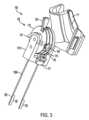
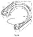
[0117]したがって、本明細書では、弓形ニードルガイドを通って円形経路または半円形経路で回転する弓形ニードルを採用するデバイス、装置、システム、および方法が提供される。それにより、弓形ニードルが弓形ニードルガイド内の隙間の間の組織を挟持するとき、縫合のための補助的な支持デバイスが必要なくなる。いくつかの実施形態では、本明細書のデバイス、装置、システム、および方法の縫合機構が、ワイヤによって作動され、それにより内視鏡的な柔軟性および操作(endoscopic flexibility and manipulation)を向上させるのを可能にする。いくつかの実施形態では、本明細書のデバイス、装置、システム、および方法が、内視鏡の主軸に対して角度をつけられた遠位側組立体を通して弓形ニードルを平行移動させる。このように相対的に角度をつけて位置合わせすることによりカメラの障害となることが防止され、縫合の正確さおよび使い易さが向上する。 [0117] Accordingly, provided herein are devices, apparatus, systems, and methods that employ an arcuate needle that rotates in a circular or semi-circular path through an arcuate needle guide. This eliminates the need for an auxiliary support device for suturing when the arcuate needle clamps tissue between gaps in the arcuate needle guide. In some embodiments, the suturing mechanism of the devices, apparatus, systems, and methods herein is wire actuated, thereby improving endoscopic flexibility and manipulation. enable In some embodiments, the devices, apparatus, systems, and methods herein translate an arcuate needle through a distal assembly that is angled with respect to the major axis of the endoscope. This relative angular alignment prevents obstruction of the camera and improves suturing accuracy and ease of use.
内視鏡的縫合システム
[0118]図1が、内視鏡140と共に使用されるように構成される例示の内視鏡的縫合システム100の図である。示されるように、例示の内視鏡的縫合システム100が、遠位側組立体120、近位側組立体110、およびケーブル130を備える。いくつかの実施形態では、内視鏡的縫合システム100が、ケーブル130の少なくとも一部分を内視鏡140に結合するケーブル固定具150をさらに備える。いくつかの実施形態では、ケーブル固定具150が、ケーブル130の少なくとも一部分を内視鏡140に取り外し可能に結合する。いくつかの実施形態では、ケーブル固定具150が、ケーブル130および内視鏡140に巻き付くことによりケーブル130を内視鏡140に固定する。いくつかの実施形態では、ケーブル固定具150が、ケーブル130および内視鏡140にクランプされることによりケーブル130を内視鏡140に固定する。いくつかの実施形態では、ケーブル固定具150が、ケーブル130を内視鏡140に取り外し可能に付着させることによりケーブル130を内視鏡140に固定する。いくつかの実施形態では、ケーブル固定具150が、圧入固定具、クランプ、接着剤、テープ、ストラップ、止めねじ、フック・ループ固定具、磁石、またはその任意の組合せを含む。いくつかの実施形態では、内視鏡的縫合システム100が、1個、2個、3個、4個、5個、6個、7個、8個、9個、10個、またはそれ以上のケーブル固定具150を備える。Endoscopic suturing system
[0118] FIG. 1 is a diagram of an exemplary
近位側組立体
[0119]図2および3が、内視鏡140に結合された例示の近位側組立体110の図を示す。示されるように、例示の近位側組立体110が第2のハウジング111およびアクチュエータ112を備える。いくつかの実施形態では、第2のハウジング111が、第2のハウジング固定具111A、アクチュエータ支持部分111B、および主要な第2のハウジングボディ111Cを備える。いくつかの実施形態では、主要な第2のハウジングボディ111Cが、第2のハウジング固定具111Aをアクチュエータ支持部分111Bに結合する。いくつかの実施形態では、近位側組手体110が約10mmから約50mmの長さを有する。いくつかの実施形態では、近位側組立体110が最大で約50mmの長さを有する。proximal assembly
[0119] FIGS. 2 and 3 show views of an exemplary
[0120]いくつかの実施形態では、第2のハウジング111が内視鏡140に結合される。いくつかの実施形態では、第2のハウジング111が内視鏡140に取り外し可能に結合される。いくつかの実施形態では、第2のハウジング111が内視鏡140および内視鏡140の内視鏡的生体検査ポート140Aに結合される。いくつかの実施形態では、内視鏡的生体検査ポート140Aが器具チャンネルポートである。いくつかの実施形態では、第2のハウジング111が、内視鏡140と内視鏡ケーブル140Aとの間の接合部において内視鏡140に取り外し可能に結合される。いくつかの実施形態では、第2のハウジング111が、内視鏡140の一部分、内視鏡ケーブル140、またはその両方を囲む。いくつかの実施形態では、第2のハウジング111が、内視鏡140の一部分、内視鏡ケーブル140A、またはその両方を部分的に囲む。いくつかの実施形態では、内視鏡140および内視鏡ケーブル140Aの両方への第2のハウジング111の結合が、内視鏡140上での近位側組立体110の安定性を向上させるのを可能にする。 [0120] In some embodiments, the
[0121]いくつかの実施形態では、第2のハウジング固定具111Aおよび主要な第2のハウジングボディ111Cが内視鏡140に結合される。いくつかの実施形態では、第2のハウジング固定具111Aおよび主要な第2のハウジングボディ111Cが内視鏡140に取り外し可能に結合される。いくつかの実施形態では、第2のハウジング固定具111Aおよび主要な第2のハウジングボディ111Cが内視鏡140および内視鏡140の内視鏡的生体検査ポート140Aに結合される。いくつかの実施形態では、第2のハウジング固定具111Aおよび主要な第2のハウジングボディ111Cが、内視鏡140と内視鏡ケーブル140Aとの間の接合部において内視鏡140に取り外し可能に結合される。いくつかの実施形態では、第2のハウジング固定具111Aおよび主要な第2のハウジングボディ111Cが、内視鏡140の一部分、内視鏡ケーブル140、またはその両方を囲む。いくつかの実施形態では、第2のハウジング固定具111Aおよび主要な第2のハウジングボディ111Cが、内視鏡140の一部分、内視鏡ケーブル140A、またはその両方を部分的に囲む。いくつかの実施形態では、内視鏡140および内視鏡ケーブル140Aの両方への第2のハウジング固定具111Aおよび主要な第2のハウジングボディ111Cの結合が、内視鏡140上での近位側組立体110の安定性を向上させるのを可能にする。いくつかの実施形態では、第2のハウジング111Aの固定具が、内視鏡140と第2のハウジング111との間でのいかなる相互モーションも可能にすることなく、内視鏡140に堅固に接続される。 [0121] In some embodiments, the
[0122]示されるように、主要な第2のハウジングボディ111Cが、第1の凹形部分および第2の凹形部分を備える。いくつかの実施形態では、第1の凹形が内視鏡140の一部分を囲む。いくつかの実施形態では、第2の凹形が内視鏡ケーブル140Aの一部分を囲む。いくつかの実施形態では、第1の凹形部分が、内視鏡140の外径と等しいかまたはそれより大きい内径を有する。いくつかの実施形態では、第1の凹形部分の内径が約5mmから約50mmである。いくつかの実施形態では、第2の凹形部分が内視鏡ケーブル140Aの外径と等しいかまたはそれより大きい内径を有する。いくつかの実施形態では、第2の凹形部分の内径が約5mmから約50mmである。いくつかの実施形態では、第1の凹形部分の中心線と第2の凹形部分の中心線との間の角度が約30度である。いくつかの実施形態では、第1の凹形部分の中心線と第2の凹形部分の中心線との間の角度が、その中での増加も含めて、約5度、10度、15度、20度、25度、30度、35度、40度、45度、50度、55度、60度、65度、70度、75度、80度、85度、90度である。いくつかの実施形態では、第1の凹形部分の中心線と第2の凹形部分の中心線との間の角度が、約5から約90度、約10から約90度、約10から約80度、約20から約70度、約5から約60度、約10から約60度、約20から約60度、約10から約50度、約5から約45度、約10から約50度、約15から約65度、約25から約65度、約30から約60度、5から90度、10から90度、10から80度、20から70度、5から60度、10から60度、20から60度、10から50度、5から45度、10から50度、15から65度、25から65度、または30から60度である。いくつかの実施形態では、主要な第2のハウジングボディ111Cの第1の凹形部分または第2の凹形部分の少なくとも1つが一様な厚さを有する。 [0122] As shown, the main
[0123]いくつかの実施形態では、主要な第2のハウジングボディ111Cが、第2のハウジング固定具111Aに結合される固定機構を備える。示されるように、主要な第2のハウジングボディ111Cの固定機構が複数の一段高い隆起部分を備える。別法として、いくつかの実施形態では、主要な第2のハウジングボディ111Cの固定機構が、留め具、ストリング、バンド、フック・ループ固定具、テープ、ストラップ、磁石、シンチ、圧入具、止めねじ、接着剤、またはその任意の組合せを含む。 [0123] In some embodiments, the main
[0124]いくつかの実施形態では、第2のハウジング固定具111Aが主要な第2のハウジングボディ111Cの固定機構に結合され、それにより近位側組立体110を内視鏡140に固着する。見られるように、例示の第2のハウジング固定具111Aが、主要な第2のハウジングボディ111Cから延在するストラップを備える。いくつかの実施形態では、第2のハウジング固定具111Aおよび主要な第2のハウジングボディ111Cがヒンジ(図示せず)によって結合され、ここでは、第2のハウジング固定具111Aがヒンジを介して主要な第2のハウジングボディ111Cを中心として回転する。いくつかの実施形態では、第2のハウジング固定具111Aが、主要な第2のハウジングボディ111Cに永久的に取り付けられる可撓性ストラップを備える。いくつかの実施形態では、第2のハウジング固定具111Aが、主要な第2のハウジングボディ111Cの上にオーバーモールドされる可撓性ストラップを備える。いくつかの実施形態では、第2のハウジング固定具111Aの少なくとも一部分が可撓性である。さらに、示されるように、第2のハウジング固定具111Aのストラップの終端部が、主要な第2のハウジングボディ111Cの固定機構に係合されたり固定機構から係合解除されたりするフックを備える。加えて、示されるように、いくつかの実施形態では、主要な第2のハウジングボディ111Cの固定機構が、主要な第2のハウジングボディ111Cの固定機構との係合および係合解除中に使用者によって握持されるための突き出し部分を備える。いくつかの実施形態では、第2のハウジング固定具111Aのストラップが、主要な第2のハウジングボディ111Cの固定機構に係合されたり固定機構から係合解除されたりするフックを備える。いくつかの実施形態では、第2のハウジング固定具111Aのストラップおよび主要な第2のハウジングボディ111Cの固定機構が、第2のハウジング111を多様なサイズの内視鏡140に固着するのを可能にする。いくつかの実施形態では、第2のハウジング固定具111Aのフックおよび。 [0124] In some embodiments, the
[0125]いくつかの実施形態では、第2のハウジング111が、1個、2個、3個、4個、5個、6個、7個、8個、9個、10個、またはそれ以上の第2のハウジング固定具111Aを備える。別法として、第2のハウジング111が内視鏡140に結合されない。いくつかの実施形態では、近位側組立体110が、手持ち式の組立体として使用されるように構成される。いくつかの実施形態では、近位側組立体110が、表面、棒、スタンド、またはその任意の組合せに設置されるように構成される。 [0125] In some embodiments, the
[0126]いくつかの実施形態では、ホイール113が、第2のハウジング111を基準とした少なくとも1自由度で回転するように制限される。いくつかの実施形態では、アクチュエータ支持部分111Bがピン114を収容するための孔を備える。いくつかの実施形態では、アクチュエータ支持部分111Bがアクチュエータ112の少なくとも一部分を取り囲む。見られるように、例示のアクチュエータ112が、第2のハウジング111内でピン114を中心として回転するホイール113を備える。いくつかの実施形態では、アクチュエータ112が第2のハウジング111内でピン114を中心として自由に回転する。いくつかの実施形態では、第2のハウジング111、ピン114、またはホイール113、のうちの少なくとも1つが、第2のハウジング111内でピン114を中心としてホイール113が回転するのを可能にする軸受を備える。いくつかの実施形態では、ホイール113またはアクチュエータ支持部分111Bの少なくとも1つがロックを備え、ここでは、ピン114を中心としたホイール113の回転がロックにより単一の位置で一時的にロックされる。いくつかの実施形態では、第2のハウジング111、ピン114、またはホイール113、のうちの少なくとも1つが、ホイール113を手動で前進させるのを可能にすることを目的としてピン114を中心としたホイール113の回転時に結合されたり切り離されたりする、窪み部分、隆起部分、谷部分、ばね、またはその任意の組合せを備える。いくつかの実施形態では、窪み部分、隆起部分、谷部分、ばね、またはその任意の組合せが、回転角度の増分を示す触覚フィードバックを提供することを目的としてピン114を中心としたホイール113の回転時に係合されたり切り離されたりする。加えて、いくつかの実施形態では、アクチュエータ112が、第2のハウジング111を基準としてアクチュエータ112を1つまたは複数の位置まで付勢するために、ばね、窪み部分、磁石、またはその任意の組合せをさらに備える。 [0126] In some embodiments, the
[0127]別法として、いくつかの実施形態では、第2のハウジング111がピン114を有さず、ここでは、ホイール113がアクチュエータ支持部分111B内で突出部を中心として回転する。いくつかの実施形態では、ホイール113がピン114または突き出し部分を備え、ここでは、ホイール113およびピン114または突き出し部分がアクチュエータ支持部分111B内で対応する孔を中心として回転する。別法として、いくつかの実施形態では、ホイール113が、円形チャンネル、ばね、カム、ピン、ねじ、ボルト、またはその任意の組合せを介して、第2のハウジング111を基準として回転するように制限される。いくつかの実施形態では、ピン114がホイール113を洗浄するために取り外し可能である。図3に示されるように、ホイール113が円形である。いくつかの実施形態では、円形ホイール113が外径を有する。別法として、いくつかの実施形態では、ホイール113が、三角形、正方形、五角形、六角形、または任意の他の多角形を含む形状を有する。 [0127] Alternatively, in some embodiments,
[0128]示されるように、例示のアクチュエータ112が、使用者が第2のハウジング111を中心としてホイール113を回転させるのを可能にするノブ119を備える。いくつかの実施形態では、ノブ119が、第2のハウジング111を基準としたアクチュエータ112の位置のインジケータとしてさらに機能する。いくつかの実施形態では、ノブ119が、ホイール113が1次方向131において360度以上回転するのをまたはホイール113が1次方向131の反対の2次方向において360度以上回転するのを防止する。いくつかの実施形態では、ホイール113が1次方向131において最大で約360度回転し、1次方向131と反対の2次方向において最大で約360度回転する。いくつかの実施形態では、ホイール113が、1次方向131において、最大で、約20度、約30度、約40度、約50度、約60度、約70度、約80度、約90度、約110度、約120度、約130度、約140度、約150度、約160度、約170度、約180度、約190度、約200度、約210度、約220度、約230度、約240度、約250度、約260度、約270度、約280度、約290度、約300度、約310度、約320度、約330度、約340度、約350度、または約360度で、回転し、1次方向131の反対の2次方向において、最大で、約20度、約30度、約40度、約50度、約60度、約70度、約80度、約90度、約110度、約120度、約130度、約140度、約150度、約160度、約170度、約180度、約190度、約200度、約210度、約220度、約230度、約240度、約250度、約260度、約270度、約280度、約290度、約300度、約310度、約320度、約330度、約340度、約350度、または約360で、回転する。いくつかの実施形態では、アクチュエータ112が、第2のハウジング111を基準としたその位置を示すインジケータをさらに備える。別法として、いくつかの実施形態では、アクチュエータ112が、プーリー、ホイール、クランプ、ノット部分(knot)、ポスト、ギア、コグ、チェーン、またはその任意の組合せを備えるかまたはさらに備える。 [0128] As shown, the
[0129]示されるように、例示のホイール113が、ケーブル132の第1の部分を受ける第1のチャンネル115、および第2のケーブル部分133を受ける第2のチャンネル116を備える。いくつかの実施形態では、第1のチャンネル115または第2のチャンネル116の少なくとも1つが円形断面を有する。いくつかの実施形態では、ホイール113が第2のチャンネル116を備えない。このような実施形態では、第1のチャンネル115が単一の螺旋チャンネルを備える。いくつかの実施形態では、第1のチャンネル115または第2のチャンネル116の少なくとも1つが、ケーブル130の幅と等しいかまたはそれより大きい内幅を有する。いくつかの実施形態では、第1のチャンネル115の半径が第2のチャンネル116の半径と等しい。いくつかの実施形態では、第1のチャンネル115の半径が第2のチャンネル116の半径より大きい。いくつかの実施形態では、第1のチャンネル115の半径が第2のチャンネル116の半径より小さい。いくつかの実施形態では、第1のチャンネルの円周が第2のチャンネル116の円周と等しい。いくつかの実施形態では、第1のチャンネル115の円周が第2のチャンネル116の円周より大きい。いくつかの実施形態では、第1のチャンネル115の円周が第2のチャンネル116の円周より小さい。いくつかの実施形態では、第1のチャンネル115および第2のチャンネル116が同心である。いくつかの実施形態では、第1のチャンネル115および第2のチャンネル116が非同心である。いくつかの実施形態では、第1のチャンネル115および第2のチャンネル116が重なる。 [0129] As shown, the
[0130]いくつかの実施形態では、アクチュエータ112が、第1のケーブル部分132をホイール113に結合する第1の固定具118、および第2のケーブル部分130をアクチュエータ112に結合する第2の固定具(図示せず)をさらに備える。いくつかの実施形態では、第1の固定具118が、第1のケーブル部分133を第1のチャンネル115内で維持する。いくつかの実施形態では、第2の固定具が第2のケーブル部分133を第2のチャンネル116内で維持する。いくつかの実施形態では、第1の固定具118が、ホイール113が1次方向131において360度以上回転するのをまたはホイール113が1次方向131と反対の2次方向において360度以上回転するのを防止する。いくつかの実施形態では、近位側組立体110が、1個、2個、3個、4個、5個、6個、7個、8個、9個、10個、またはそれ以上の固定具を備える。いくつかの実施形態では、ホイール113が第1の固定具118または第2の固定具を備えない。いくつかの実施形態では、ホイール113が、第1のケーブル部分132、第2のケーブル部分133、またはその両方をホイール113に結合する、ノブ、留め具、または突き出し部分を備える。いくつかの実施形態では、第1のケーブル部分132および第2のケーブル部分133が接続され、ここでは、ケーブル130が1つまたは複数の構成要素を備える。いくつかの実施形態では、ケーブル130が2つ以上の構成要素を備える。いくつかの実施形態では、第1のケーブル部分132および第2のケーブル部分133が接続されず、ここでは、ケーブル130が2つ以上の構成要素を備える。いくつかの実施形態では、第1のケーブル部分132または第2のケーブル部分133の少なくとも1つが、アクチュエータ112のホイール113の回転中に常に張力を受ける。いくつかの実施形態では、第1のケーブル部分132または第2のケーブル部分133の少なくとも1つが、アクチュエータ112のホイール113の回転中にたるみを有さない。いくつかの実施形態では、第1のケーブル部分132または第2のケーブル部分133の少なくとも1つが、1次方向131においてアクチュエータ112のホイール113が回転させられるとき、張力を受ける。いくつかの実施形態では、第1のケーブル部分132または第2のケーブル部分133の少なくとも1つが、1次方向131と反対の2次方向においてアクチュエータ112のホイール113が回転させられるとき、張力を受ける。 [0130] In some embodiments, the
[0131]いくつかの実施形態では、図3によると、アクチュエータ112が、1次方向131において回転させられるとき、第2のハウジング111から離すように第1のケーブル部分132を第1の距離だけ平行移動させ、第2のハウジング111の方に第2のケーブル部分133を第2の距離だけ平行移動させる。いくつかの実施形態では、アクチュエータ112が、1次方向132の反対の2次方向において回転させられるとき、第2のハウジングの方に第1のケーブル部分132を第3の距離だけ平行移動させ、第2のハウジング111から離すように第2のケーブル部分133を第4の距離だけ平行移動させる。いくつかの実施形態では、第1の距離、第2の距離、第3の距離、および第4の距離が等しい。いくつかの実施形態では、第1の距離、第2の距離、第3の距離、または第4の距離のうちの少なくとも2つが等しい。いくつかの実施形態では、第1の距離が第3の距離と等しく、第2の距離が第4の距離と等しい。 [0131] In some embodiments, according to FIG. 3, when the
[0132]図3に見られるように、いくつかの実施形態では、内視鏡的縫合システム100が、ケーブル130の少なくとも一部分を囲むシース130Aをさらに備える。いくつかの実施形態では、ケーブル130が、シース130A内で一方向において前後に自由に平行移動する。いくつかの実施形態では、ケーブル130およびシース130AがBowdenケーブルを備える。いくつかの実施形態では、ケーブル130が、マルチストランドケーブル、シングルストランドケーブル、ロープ、スレッド、ストリング、ワイヤ、またはその任意の組合せを含む。いくつかの実施形態では、ケーブル130が、1個、2個、3個、4個、5個、6個、7個、8個、9個、10個、またはそれ以上のケーブルを備える。いくつかの実施形態では、ケーブル130の少なくとも一部分がケーブルシース130Aによって覆われない。いくつかの実施形態では、ケーブル130が剛体である。いくつかの実施形態では、ケーブル130が弾性ではない。いくつかの実施形態では、ケーブルシース130Aが、ケーブル130を中で保護する中空チューブを備える。いくつかの実施形態では、ケーブルシース130Aが剛体である。いくつかの実施形態では、ケーブルシース130が弾性ではない。いくつかの実施形態では、ケーブル130が、ニードル122の内視鏡的な柔軟性および操作を向上させるのを可能にする。 [0132] As seen in FIG. 3, in some embodiments, the
[0133]示されるように、第2のハウジング111が、シース130Aを第2のハウジング111に結合する近位側シース固定具117を備える。示されるように、シース固定具117が第2のハウジング111のアクチュエータ支持部分111Bに接続される。別法として、いくつかの実施形態では、シース固定具117が第2のハウジング111の任意の部分に接続される。いくつかの実施形態では、近位側シース固定具117が第2のハウジング111を基準としてシース130Aの一部分を固定し、その結果、ホイール113の回転時にケーブル130がシース130A内で移動することが可能となる。いくつかの実施形態では、近位側シース固定具117が、ホイール113が1次方向131において360度以上回転するのをまたはホイール113が1次方向131の反対の第2の方向において360度以上回転するのを防止する。示されるように、例示の近位側シース固定具117がクランプを備える。いくつかの実施形態では、クランプが、第1のプレートと、第2のプレートと、第1のプレートと第2のプレートとの間でケーブル130を締め付ける1つまたは複数のねじとを備える。別法として、いくつかの実施形態では、近位側シース固定具117が、ねじ、留め具、テープ、ボルト、ナット、またはその任意の組合せを備える。いくつかの実施形態では、近位側組立体110が、第1のケーブル部分132のための少なくとも1つの近位側シース固定具117、および第2のケーブル部分133のための少なくとも1つの近位側シース固定具117を備える。いくつかの実施形態では、近位側組立体110が、第1のケーブル部分132および第2のケーブル部分133の両方ための単一の近位側シース固定具117を備える。いくつかの実施形態では、近位側組立体110が、1個、2個、3個、4個、5個、6個、7個、8個、9個、10個、またはそれ以上の近位側シース固定具117を備える。 [0133] As shown, the
[0134]いくつかの実施形態では、ケーブル130が、ファブリック、金属、プラスチック、炭素、またはその任意の組合せから構成される。いくつかの実施形態では、第2のハウジング111、アクチュエータ112、ホイール113、ピン114、近位側シース固定具117、第1の固定具118、またはシース130A、のうちの少なくとも1つが、プラスチック、金属、ガラス繊維、炭素繊維、木材、またはその任意の組合せから構成される。いくつかの実施形態では、アクチュエータが、クランク、ギア、ラック、またはピニオン、のうちの少なくとも1つを備えない。図64および図65が例示の近位側組立体の画像を示す。 [0134] In some embodiments,
[0135]いくつかの実施形態では、ケーブル130、ケーブル固定具150、シース130A、アクチュエータ112、またはその任意の組合せの、長さ、組成、構成、またはその任意の組合せが、ニードルの正確な作動により、内視鏡的な柔軟性および操作を向上させるのを可能にする。いくつかの実施形態では、ケーブル130およびシース130Aの直径が、より小さい内視鏡チャンネルを使用するのを可能にするために最小化される。 [0135] In some embodiments, the length, composition, configuration, or any combination thereof, of the
第1の遠位側組立体
[0136]図4~図6が、例示の第1の遠位側組立体120の図を示す。示されるように、例示の第1の遠位側組立体120が、第1のハウジング121、および、第1のハウジング121内にある弓形ニードル122を備える。いくつかの実施形態では、第1のハウジング121が内視鏡140に連結される。いくつかの実施形態では、組織が、縫合プロセスを通して、弓形ニードル122に接触する形で支持される。いくつかの実施形態では、第1の遠位側組立体120が、アンカー交換カテーテルを備えない。いくつかの実施形態では、第1の遠位側組立体120が、弓形ニードル122に接触させた状態で組織を維持するための専用のグラバーを必要としない。いくつかの実施形態では、必要となる専用のグラバーがないことにより、追加の専用の作業用チャンネルなしで標準的な内視鏡140を使用することが可能となる。first distal assembly
[0136] FIGS. 4-6 show views of an exemplary first
[0137]いくつかの実施形態では、図5によると、ニードル軸501が、内視鏡140の遠位側の軸(または、主軸)502に対して傾斜する。いくつかの実施形態では、ニードル軸501が、内視鏡140の遠位側の軸502に対して一方向に傾斜する。いくつかの実施形態では、ニードル軸501および内視鏡140の遠位側の軸502が平行または垂直ではない。いくつかの実施形態では、ニードル軸501と内視鏡140の遠位側の軸502との間の角度が、約5度から約85度である。いくつかの実施形態では、ニードル軸501と内視鏡140の遠位側の軸502との間の角度が、約5度から約85度の範囲内で調整可能である。いくつかの実施形態では、ニードル軸501と内視鏡140の遠位側の軸502との間の特定の角度が、弓形ニードルの入口、出口、またはその両方、および縫合されている組織を、内視鏡140のカメラが視認するのを可能にする。いくつかの実施形態では、ニードル軸501が、弓形ニードル123の対称面に対して垂直であって弓形ニードル123の半径の中心に一致する軸として定義される。いくつかの実施形態では、内視鏡140の遠位側の軸502が、内視鏡140の遠位側部分の中心軸または主軸として定義される。いくつかの実施形態では、内視鏡140の遠位側の軸502が、第1のハウジング112の内視鏡固定具121Aの中心軸として定義される。いくつかの実施形態では、弓形ニードルガイド121Bの中心軸501と内視鏡140の遠位側の軸502との間の角度が、最大の、最小の、または平均の角度として定義される。 [0137] In some embodiments, according to FIG. In some embodiments,
[0138]いくつかの実施形態では、遠位側組立体が、弓形ニードル122の少なくとも一部分を収めるように構成された弓形ニードルガイド121Bを備える。いくつかの実施形態では、本明細書のデバイス、装置、およびシステムが、弓形ニードルガイド121Bを通して弓形ニードル122を作動させる。 [0138] In some embodiments, the distal assembly comprises an
[0139]いくつかの実施形態では、弓形ニードルガイド121Bが、第1の終端部ポイント、および、第1の終端部ポイントの反対側にある第2の終端部ポイントを有し、ここでは、隙間604が第1の終端部ポイントと第2の終端部ポイントとの間に形成される。いくつかの実施形態では、図6によると、第1の終端部ポイントが第1のピン固定具603と正接関係にあり、第2の終端部ポイントが、第1の遠位側組立体120内の対向する第2のピン固定具603と正接関係にある。いくつかの実施形態では、第1の終端部ポイントおよび第2の終端部ポイントが、約180度未満、170度未満、160度未満、150度未満、145度未満、120度未満、または100未満の角度で、分離される。いくつかの実施形態では、第1の終端部ポイントおよび第2の終端部ポイントが、約100度から約180度の角度で、分離される。いくつかの実施形態では、第1の終端部ポイントと第2の終端部ポイントとの間の分離角度が、ニードル軸501に対して垂直であり、第1の終端部ポイントと正接関係にあるポイントに一致する、第1の軸と、ニードル軸501に対して垂直であり、第2の終端部ポイントと正接関係にあるポイントに一致する、第2の軸との間の角度として測定される。いくつかの実施形態では、隙間604が、弓形ニードル122によって縫合されるための組織を受け入れる。いくつかの実施形態では、隙間604が弓形ニードル122が組織を挟持するのを可能にし、それにより補助的な支持デバイスの必要性を排除する。 [0139] In some embodiments, the
[0140]いくつかの実施形態では、第1のハウジング121が、内視鏡固定部121Aにより内視鏡140に連結される。いくつかの実施形態では、第1の遠位側組立体120が、1個、2個、3個、4個、5個、6個、7個、8個、9個、10個、またはそれ以上の内視鏡固定具121Aを備える。いくつかの実施形態では、内視鏡固定具121Aが、第1のハウジング121を内視鏡140に連結する。いくつかの実施形態では、内視鏡固定具121Aが第1のハウジング121を内視鏡140に取り外し可能に結合する。示されるように、内視鏡固定具121Aが圧入固定具を備える。いくつかの実施形態では、圧入式の内視鏡固定具121Aが、圧入式の内視鏡固定具121Aを内視鏡140の遠位端の上に堅固に押圧することにより、内視鏡140に取り付けられる。いくつかの実施形態では、圧入式の内視鏡固定具121Aが、圧入式の内視鏡固定具121Aを内視鏡140の遠位端の上まで堅固に押圧して回転させることにより、内視鏡140に取り付けられる。いくつかの実施形態では、圧入式の内視鏡固定具121が、圧入式の内視鏡固定具121Aを強く引いて内視鏡140の遠位端から離すことにより、内視鏡140から脱着される。いくつかの実施形態では、圧入式の内視鏡固定具121Aが、圧入式の内視鏡固定具121Aを強く引いて回転させて内視鏡140の遠位端から離すことにより、内視鏡140から脱着される。別法として、いくつかの実施形態では、内視鏡固定具121Aが、クランプ、接着剤、テープ、ストラップ、止めねじ、フック・ループ固定具、磁石、またはその任意の組合せを含む。 [0140] In some embodiments, the
[0141]示されるように、いくつかの実施形態では、内視鏡固定具121Aが円形である。いくつかの実施形態では、内視鏡140が約5mmから約16mmの遠位側の外径を有する。したがって、いくつかの実施形態では、内視鏡固定具121Aが約5mmから約16mmの内径を有する。いくつかの実施形態では、内視鏡固定具121Aが、最低で、約5mmの内径を有する。いくつかの実施形態では、内視鏡固定具121Aが、最大で、約16mmの内径を有する。いくつかの実施形態では、圧入式の内視鏡固定具121Aが、内視鏡140の直径と等しいかまたはそれより小さい直径を有する。いくつかの実施形態では、内視鏡固定具121Aが、内視鏡140の直径と等しいかまたはそれより大きい直径を有する。いくつかの実施形態では、内視鏡固定具121Aがテーパ状であり、第1の内径および第2の内径を有し、ここでは、第1の内径が第2の内径の遠位側にある。いくつかの実施形態では、第1の内径が第2の内径より大きい。いくつかの実施形態では、第2の内径が第1の内径より大きい。いくつかの実施形態では、内視鏡固定具121Aの直径が、最大の、最小の、または平均の内幅として測定される。いくつかの実施形態では、内視鏡140の直径が、最大の、最小の、または平均の外幅として測定される。別法として、いくつかの実施形態では、内視鏡固定具121Aが、三角形、正方形、六角形、または任意の他の多角形を含む断面形状を有する。いくつかの実施形態では、内視鏡固定具121Aが、約10mmから約30mmの内部長さを有する。いくつかの実施形態では、内視鏡固定具121Aの内部長さが、内視鏡固定具121Aの遠位側終端部から内視鏡固定具121Aの近位側終端部までの、最小の、最大の、または平均の長さとして測定される。いくつかの実施形態では、内視鏡固定具121Aの内部長さが、内視鏡固定具121Aの遠位側終端部から内視鏡固定具121Aの近位側終端部までの、最小の、最大の、または平均の垂直方向の長さとして測定される。いくつかの実施形態では、内視鏡固定具121Aの数および/または構成が、弓形ニードル122を正確に平行移動させるのを可能にするための、内視鏡140との堅固な接続を確立する。 [0141] As shown, in some embodiments, the
[0142]図4に示されるように、例示の第1の遠位側組立体120が、シース130Aの一部分を第1のハウジング121に結合する遠位側シース固定具128をさらに備える。示されるように、第1のハウジング121が、シース130Aを第1のハウジング121に結合する遠位側シース固定具117を備える。いくつかの実施形態では、遠位側シース固定具117が第1のハウジング121を基準としてシース130Aの一部分を固定し、その結果、ホイールの回転時、ケーブル130がシース130A内で移動することが可能となる。示されるように、例示の遠位側シース固定具128がクランプを備える。いくつかの実施形態では、遠位側シース固定具128が、プレートと、プレートと第1のハウジング121との間でケーブルシース130Aを締め付ける1つまたは複数のシース固定具ねじ128Aとを備える。別法として、いくつかの実施形態では、遠位側シース固定具128が、ねじ、留め具、テープ、またはその任意の組合せを備える。いくつかの実施形態では、第1のハウジング112が、第1のケーブル部分132のための少なくとも1つの遠位側シース固定具128、および第2のケーブル部分1333のための少なくとも1つの遠位側シース固定具128を備える。いくつかの実施形態では、第1のハウジング112が、第1のケーブル部分132および第2のケーブル部分133の両方のための遠位側シース固定具128を備える。いくつかの実施形態では、ケーブルシース130Aの一部分が遠位側シース固定具128の終端箇所を通過して第1のハウジング121の中まで延在する。いくつかの実施形態では、遠位側組立体120が、1個、2個、3個、4個、5個、6個、7個、8個、9個、10個、またはそれ以上の遠位側シース固定具128を備える。別法として、いくつかの実施形態では、遠位側シース固定具128が、クランプ、留め具、バンド、フック・ループ固定具、接着剤、またはその任意の組合せを備える。いくつかの実施形態では、ケーブルシース130Aが、ニードルの正確な作動により、内視鏡的な柔軟性および操作を向上させるのを可能にする。いくつかの実施形態では、ケーブル130およびシース130Aの直径が、より小さい内視鏡チャンネルを使用するのを可能にするために最小化される。 [0142] As shown in FIG. As shown,
[0143]図6~9が、例示の第1の遠位側組立体120の詳細図を示す。図6によると、例示の第1のハウジング121が、1次の第1のハウジング部分601、2次の第1のハウジング部分602、およびピン固定具603を備える。いくつかの実施形態では、2次の第1のハウジング部分602が1次の第1のハウジング部分601の中に嵌め込まれる。いくつかの実施形態では、1次の第1のハウジング部分601および2次の第1のハウジング部分602がピン固定具603によって接合される。いくつかの実施形態では、1次の第1のハウジング部分601および2次の第1のハウジング部分602がピン固定具603により取り外し可能に接合される。いくつかの実施形態では、1次の第1のハウジング部分601および2次の第1のハウジング部分602が同じ材料で作られる。いくつかの実施形態では、1次の第1のハウジング部分601および2次の第1のハウジング部分602が異なる材料で作られる。示されるように、例示のピン固定具603が圧入固定具を備え、ここでは、圧入固定具が、1次の第1のハウジング部分601および2次の第1のハウジング部分602の中の対応する孔の直径より大きい外径を有する。別法として、いくつかの実施形態では、ピン固定具603が、ねじ、ボルト、ねじ構造部、ナット、リベット、接着剤、プーリー、軸受、溶接部、またはその任意の組合せを含む。示されるように、例示の第1のハウジング121が2つのピン固定具603を備える。別法として、例示の第1のハウジング121が、1個、2個、3個、4個、5個、6個、7個、8個、9個、10個、またはそれ以上のピン固定具603を備える。 [0143] FIGS. 6-9 show detailed views of an exemplary first
[0144]さらに、いくつかの実施形態では、第1の遠位側組立体120が、第1のハウジング121内の弓形ニードルガイド121B内に配置される弓形ニードル122を備える。いくつかの実施形態では、1次の第1のハウジング部分601または2次の第1のハウジング部分602の少なくとも1つが弓形ニードルガイド121Bを備える。いくつかの実施形態では、弓形ニードル122が弓形ニードルガイド121B内で自由に摺動する。いくつかの実施形態では、弓形ニードルガイド121Bが1自由度の範囲内で弓形ニードル122を回転させるように制限する。いくつかの実施形態では、弓形ニードルガイド121Bが、少なくとも1回転自由度の範囲内で弓形ニードル122を回転させるように制限する。見られるように、例示の弓形ニードルガイド121Bが弓形ニードル122の少なくとも一部分を包囲する。いくつかの実施形態では、例示の弓形ニードルガイド121Bが、第1のハウジング121内に配置されるときの弓形ニードル122の少なくとも一部分を包囲する。いくつかの実施形態では、弓形ニードルガイド121Bが、弓形ニードル122の厚さより大きい内幅を有する。いくつかの実施形態では、弓形ニードルガイド121Bが、円形、正方形、長方形、または任意の他の多角形を含めた、断面形状を有する。いくつかの実施形態では、隙間604が、第1の遠位側組立体120内で、弓形ニードルガイド121Bの第1の終端箇所と弓形ニードルガイド121Bの第2の反対側の終端箇所との間に形成される。本明細書で見られるように、弓形ニードルガイド121Bが、弓形ニードル122の断面円周(cross sectional circumference)の約280度を囲む。別法として、いくつかの実施形態では、弓形ニードルガイド121Bが、その中での増加も含めて、弓形ニードル122の断面円周の、約100度、120度、140度、160度、180度、200度、220度、240度、260度、280度、300度、320度以上を囲む。いくつかの実施形態では、弓形ニードルガイド121Bが、弓形ニードル122の断面円周の、少なくとも、約100度、120度、140度、160度、180度、200度、220度、240度、260度、280度、300度、320度以上を囲む。 [0144] Further, in some embodiments, the first
[0145]図7~9によると、例示の第1の遠位側組立体120が、爪124を有するシャトル123をさらに備える。示されるように、例示のシャトル123が第1のハウジング121内のシャトルガイド121C内を平行移動する。いくつかの実施形態では、第1のハウジング121内のシャトル123またはシャトルガイド121Cの少なくとも1つが弓形である。いくつかの実施形態では、シャトル123がシャトルガイド121C内で摺動する。いくつかの実施形態では、シャトル123が、少なくとも1つの回転度で、シャトルガイド121C内で平行移動する。いくつかの実施形態では、シャトル123が、シャトルガイド121C内で、270度の円弧の範囲内で1つの回転度で、平行移動する。いくつかの実施形態では、シャトル123が、シャトルガイド121C内で、90度、100度、110度、120度、140度、160度、180度、200度、220度、240度、260度、280度、300度、320度、またはそれ以上の回転度を超える1つの回転度の円弧で、平行移動する。いくつかの実施形態では、シャトル123またはシャトルガイド121Cの少なくとも1つが、円形、正方形、長方形、または任意の他の多角形を含めた、断面形状を有する。 [0145] Referring to FIGS. As shown,
[0146]いくつかの実施形態では、1次の第1のハウジング部分601または2次の第1のハウジング部分602の少なくとも1つがシャトルガイド121Cを備える。いくつかの実施形態では、シャトル123が遠位側組立体120のシャトルガイド121C内で摺動する。示されるように、シャトル123が、弓形シャトルガイド121C内で摺動するために弓形である。いくつかの実施形態では、1次の第1のハウジング部分601がシャトル123の底部表面を制限し、2次の第1のハウジング部分602が、シャトル123の、内側表面、外側表面、および頂部表面の一部分を制限する。別法として、いくつかの実施形態では、1次の第1のハウジング部分601または2次の第1のハウジング部分602の少なくとも1つが、シャトル123の、底部表面、内側表面、外側表面、および頂部表面のうちの1つまたは複数を制限する。いくつかの実施形態では、シャトル123が、シャトルガイド121C内を平行移動するとき、1次の第1のハウジング部分601または2次の第1のハウジング部分602のうちの少なくとも1つによって制限される。示されるように、シャトル123の底部表面が1次の第1のハウジング部分601の一部分に接触し、対してシャトル123の内側部分および外側部分が2次の第1のハウジング部分602の一部分に接触する。いくつかの実施形態では、シャトル123が、シャトルガイド121C内を平行移動するとき、1次の第1のハウジング部分601または2次の第1のハウジング部分602の少なくとも1つに接触する。示されるように、シャトルガイド121Cと弓形ニードルガイド121Bとの間の弓形チャンネルが、シャトルガイド121Cを通ってシャトル123が平行移動するときに爪124が弓形ニードル122に接触するためのクリアランスを提供する。いくつかの実施形態では、弓形チャンネルが、爪124の幅より大きいが弓形ニードル122の幅より小さい幅を有する。 [0146] In some embodiments, at least one of the primary
[0147]いくつかの実施形態では、シャトル123の内側表面が、ニードル軸501に最も近いシャトル123の表面として定義される。いくつかの実施形態では、シャトル123の外側表面が、ニードル軸501から最も遠いシャトル123の表面として定義される。いくつかの実施形態では、シャトル123の頂部表面が、弓形ニードル122に最も近いシャトル123の表面として定義される。いくつかの実施形態では、シャトル123の底部表面が、弓形ニードル122の最も遠くにあるシャトル123の表面として定義される。 [0147] In some embodiments, the inner surface of the
[0148]いくつかの実施形態では、シャトルガイド121Cのアーク長さが、作動ホイールの回転中の第1のケーブル部分または第2のケーブル部分の少なくとも1つが移動する距離からシャトル123の幅を引いたものに等しい。いくつかの実施形態では、シャトル123が、作動ホイールの回転中、第1のケーブル部分または第2のケーブル部分の少なくとも1つが移動する距離だけ、シャトルガイド121C内を移動する。いくつかの実施形態では、シャトル123の長さとシャトルガイド121Cのアーク長さとの間の比が約1:3から約1:15である。いくつかの実施形態では、シャトル123の長さとシャトルガイド121Cのアーク長さとの間の比が、最低で、約1:3である。いくつかの実施形態では、シャトル123の長さとシャトルガイド121Cのアーク長さとの間の比が、最大で、約1:15である。いくつかの実施形態では、シャトルガイド121Cのアーク長さとアクチュエータのホイールの第1のチャンネルまたは第2のチャンネルの少なくとも一方の直径との間の比が約2:1から約1:5である。いくつかの実施形態では、シャトルガイド121Cのアーク長さとアクチュエータのホイールの第1のチャンネルまたは第2のチャンネルの少なくとも一方の直径との間の比が、最低で、約2:1である。いくつかの実施形態では、シャトルガイド121Cのアーク長さとアクチュエータのホイールの第1のチャンネルまたは第2のチャンネルの少なくとも一方の直径との間の比が、最大で、約1:5である。 [0148] In some embodiments, the arc length of the shuttle guide 121C subtracts the width of the
[0149]図8によると、例示のシャトル123が、ケーブル130に接続されるケーブルアタッチメント127をさらに備える。示されるように、ケーブルアタッチメント127が、ケーブル130の一部分を受けて固着する空洞を備える。別法として、いくつかの実施形態では、ケーブルアタッチメント127が、クランプ、孔、ねじ、ボルト、ナット、クリップ、ピン、またはその任意の組合せを備える。いくつかの実施形態では、ケーブルアタッチメント127が終端部ケーブルアタッチメントを備え、ここでは、ケーブルがケーブルアタッチメント127において終端する。いくつかの実施形態では、ケーブルアタッチメント127が非終端部ケーブルアタッチメントを備え、ここでは、ケーブルがケーブルアタッチメント127を通過してケーブルアタッチメント127に結合される。いくつかの実施形態では、シャトル123が、1個、2個、3個、4個、5個、6個、7個、8個、9個、10個、またはそれ以上のケーブルアタッチメント127を備える。見られるように、例示のシャトル123がケーブルアタッチメント127においてケーブル130に堅固に接続され、その結果、ケーブル130にかかる張力がシャトル123を張力の方向に平行移動させる。 [0149] According to FIG. As shown,
[0150]いくつかの実施形態では、シャトル123が、爪124、クッション126、またはその両方を備える。いくつかの実施形態では、シャトル123が、爪124、クッション126、またはその両方を受け入れる空洞123Aを備える。いくつかの実施形態では、空洞123Aが、爪124の外幅、クッション126の外側、またはその両方より大きい内幅を有する。いくつかの実施形態では、空洞123Aが、シャトル123内で終端する深さを有する。いくつかの実施形態では、空洞123Aがシャトル123を通って延在する。いくつかの実施形態では、空洞123Aが、正方形、円形、三角形、六角形、または任意の他の多角形を含めた、断面形状を有する。 [0150] In some embodiments, the
[0151]いくつかの実施形態では、爪124が、弓形ニードル122のノッチ122Aに係合される方向に付勢される。いくつかの実施形態では、爪124が第1の方向1000に付勢される。いくつかの実施形態では、爪124が、シャトル123を中心として回転するためのピボット127を備える。いくつかの実施形態では、ピボット127が、爪124のピン突き出し部分要素を備える。いくつかの実施形態では、ピボット127が爪124に堅固に取り付けられるピンを備え、このピンがシャトル123内の孔を中心として回転する。いくつかの実施形態では、ピボット127がシャトル123に堅固に取り付けられるピンを備え、このピンが爪124内の孔を中心として回転する。別法として、いくつかの実施形態では、ピボット127が、爪124、シャトル123、またはその両方の中に、窪み部分、スロット、ねじ、またはその任意の組合せを備える。 [0151] In some embodiments, the
[0152]いくつかの実施形態では、爪124がクッション126により係合される方向に付勢される。いくつかの実施形態では、クッション126が弾性である。いくつかの実施形態では、クッション126がばねを備える。いくつかの実施形態では、クッション126が、第1の回転方向1000の反対の第2の方向において爪124を押圧する。いくつかの実施形態では、クッション126が、弓形ニードル122のノッチ122Aに係合させることを目的として空洞123Aから外れるように爪124を上方に動かすように爪124を押圧する。いくつかの実施形態では、空洞123Aの終端箇所を基準としたピボット127の位置が、クッション126の位置との組合せで、爪を係合により付勢するのを可能にする。いくつかの実施形態では、爪124が係合されるとき、クッション126がシャトル123の空洞123Aの終端箇所に対して爪124を押圧する。いくつかの実施形態では、爪124が係合解除されるとき、弓形ニードル122がクッション126に対して爪124を押圧し、その結果、爪が上方に移動して空洞123Aの中に入り、シャトル123の空洞123Aの終端箇所から離れる。いくつかの実施形態では、爪124の上側面がシャトル123の一方の端部の方に傾斜している。いくつかの実施形態では、爪124の上側面が、第1の回転方向1000の反対の第2の回転方向において上方に傾斜している。いくつかの実施形態では、爪124の上側面が、弓形ニードルの傾斜部分に係合されるように傾斜している。いくつかの実施形態では、爪124が、ばね、湾曲部、デュアルスプリングゲート、クッション、ピストン、棒、ピン、歯、またはその任意の組合せをさらに備える。いくつかの実施形態では、第1の遠位側組立体120が、1個、2個、3個、4個、5個、6個、7個、8個、9個、10個、またはそれ以上の爪124を備える。 [0152] In some embodiments, the
[0153]いくつかの実施形態では、クッション126が爪124に一体化される。いくつかの実施形態では、クッション126がシャトル123に一体化される。いくつかの実施形態では、クッション126がシャトル123の空洞123Aに一体化される。いくつかの実施形態では、シャトル123がクッション126を備えない。いくつかの実施形態では、シャトル123がクッション126を備えず、ここでは、爪124が、弓形ニードルに対して爪124を付勢するために、湾曲部、ばね、デュアルスプリングゲート、クッション、ピストン、棒、ピン、歯、またはその任意の組合せを備える。いくつかの実施形態では、シャトル123が爪124またはクッション126を備えず、ここでは、シャトル123が、弓形ニードルに係合されたり弓形ニードルから係合解除されたりするための、湾曲部、ばね、デュアルスプリングゲート、クッション、ピストン、棒、ピン、歯、またはその任意の組合せを備える。 [0153] In some embodiments, the
[0154]さらに、図7によると、例示の第1のハウジング121が、近位側組立体から、シャトルガイド121Cを通して、シャトル123まで、またさらには第1のハウジング121から出すように、ケーブル130を案内するケーブルプーリー121Dを備える。いくつかの実施形態では、第1のハウジング121の、1次の第1のハウジング部分601、2次の第1のハウジング部分602、またはピン固定具603、の少なくとも1つが、ケーブルプーリー121Dを備える。いくつかの実施形態では、第1のハウジング121が、1個、2個、3個、4個、5個、6個、7個、8個、9個、10個、またはそれ以上のケーブルプーリー121Dを備える。いくつかの実施形態では、ケーブルプーリー121Dが、軸受、棒、湾曲表面、またはその任意の組合せを備える。いくつかの実施形態では、ケーブルプーリー121Dが、第1のハウジング121の剛体部分を備える。別法として、いくつかの実施形態では、ケーブルプーリー121Dが第1のハウジング121内で回転する。別法として、いくつかの実施形態では、ケーブルプーリー121Dが、1次の第1のハウジング部分601、2次の第1のハウジング部分602、またはその両方の中で回転する。いくつかの実施形態では、1次の第1のハウジング部分601または2次の第1のハウジング部分602の少なくとも1つが、ケーブルプーリー121Dの方におよびケーブルプーリー121Dから離すようにケーブル130を誘導する1つまたは複数のケーブルガイドをさらに備える。 [0154] Further, according to FIG. 7, exemplary
[0155]図10~13が、シャトル123および爪124により弓形ニードルガイド121Bを通って平行移動させられるときの弓形ニードル122の進行を示す。図10によると、第1の位置で、弓形ニードル122が、第1のハウジング121内の弓形ニードルガイド121B内に完全に収容される。ケーブル130が、第1のハウジング121を基準とした第1の回転方向1000において、シャトルガイド121C内でシャトル123を引くとき、図11によると、爪124が弓形ニードル122内のノッチ122Aに係合され、それにより弓形ニードル123の一部分が第1のハウジング121から出る。シャトル123が第1の回転方向1000において第1のハウジング121のシャトルガイド121C内でさらに移動することができなくなると、ケーブル130が、第1の回転方向1000の反対の第2の回転方向にシャトル123を引き、その結果、爪124が弓形ニードル122の縫合糸端部1201に係合される。次いで、ケーブル130が第1の回転方向1000に引かれ、その結果、シャトル123が第1の回転方向1000に平行移動し、対して、図12によると、爪124が弓形ニードル122の縫合糸端部1201を押圧し、その結果、弓形ニードル122の大部分が第1のハウジング121から出て、弓形ニードル122の尖った端部1101の一部分および縫合糸端部1201のみが第1のハウジング121内に存在する。シャトル123が第1のハウジング121のシャトルガイド121C内で第1の回転方向1000にさらに移動することができなくなった後、図13によると、ケーブル130が第2の回転方向において第1のハウジング121のシャトルガイド121Cを通るようにシャトル123を引き、その結果、爪124が弓形ニードル122内のノッチ122Aに再係合される。次いで、ケーブル130が、第1のハウジング121のシャトルガイド121C内で第2の回転方向にシャトル123を引き、それにより弓形ニードル122を第1の回転方向100に平行移動させて第1のハウジング121の中に戻し、それにより1回の縫合を実施する。 [0155] FIGS. 10-13 illustrate the advancement of
[0156]したがって、1回の縫合操作が、第1の方向1000にケーブル130を引くことと、第1の方向1000の反対の第2の方向にケーブル130を引くことと、2回目として第1の方向1000の方向にケーブル130を引くことと、2回目として第2の方向1000にケーブル130を引くことと、3回目として第1の方向1000にケーブル130を引くことと、3回目として第2の方向にケーブル130を引くことと、を含む。示されるように、第1の回転方向1000が第1のハウジング121を基準として反時計回りである。別法として、いくつかの実施形態では、第1の回転方向1000が第1のハウジング121を基準として時計回りである。 [0156] Thus, one suturing operation involves pulling
[0157]いくつかの実施形態では、図3、4、および10によると、第1の回転方向1000にケーブル130を引くことが、近位側組立体110の第2のハウジング111の方に1次ケーブル部分132を引くことを含む。いくつかの実施形態では、第1の回転方向1000にケーブル130を引くことが、1次方向131と反対の2次方向にアクチュエータ112のホイール113を回転させることを含む。いくつかの実施形態では、第1の回転方向1000と反対の第2の回転方向にケーブル130を引くことが、近位側組立体110の第2のハウジング111の方に2次ケーブル部分133を引くことを含む。いくつかの実施形態では、第1の回転方向1000と反対の第2の回転方向にケーブル130を引くことが、1次方向131にアクチュエータ112のホイール113を回転させることを含む。いくつかの実施形態では、第1の回転方向1000にシャトル123を平行移動させることが、近位側組立体110の第2のハウジング111の方に1次ケーブル部分132を引くことを含む。いくつかの実施形態では、第1の回転方向1000にシャトル123を平行移動させることが、1次方向131と反対の2次方向にアクチュエータ112のホイール113を回転させることを含む。いくつかの実施形態では、第1の回転方向1000と反対の第2の回転方向にシャトル123を平行移動させることが、近位側組立体110の第2のハウジング111の方に2次ケーブル部分133を引くことを含む。いくつかの実施形態では、第1の回転方向1000と反対の第2の回転方向にシャトル123を平行移動させることが、1次方向131にアクチュエータ112のホイール113を回転させることを含む。 [0157] In some embodiments, according to FIGS. Including pulling the
[0158]いくつかの実施形態では、第1の方向1000または第2の方向にケーブル130によって引かれるとき、シャトル123がシャトルガイド121C内で1つまたは複数の回転度で平行移動する。いくつかの実施形態では、第1の方向1000または第2の方向にケーブル130によって引かれるとき、シャトル123がシャトルガイド121C内で270度の円弧の範囲内で1つの回転度で平行移動する。いくつかの実施形態では、第1の方向1000または第2の方向にケーブル130によって引かれるとき、シャトル123が、その中での増加も含めて、90度、100度、110度、120度、140度、160度、180度、200度、220度、240度、260度、280度、300度、320度、またはそれ以上の回転度の範囲内の1つの回転度の円弧で、シャトルガイド121C内で、平行移動する。 [0158] In some embodiments, when pulled by
[0159]いくつかの実施形態では、第1のハウジング111、弓形ニードル112、シャトル123、爪124、シャトル125、クッション126、1次の第1のハウジング部分601、2次の第1のハウジング部分602、またはピン固定具603、のうちの少なくとも1つが、プラスチック、金属、ガラス繊維、炭素繊維、木材、またはその任意の組合せから構成される。 [0159] In some embodiments,
弓形ニードルおよび縫合糸
[0160]図14~18が例示の弓形ニードル122および縫合糸125の図を示す。図14および15によると、いくつかの実施形態では、弓形ニードル122が、ノッチ122A、尖った端部1101、および縫合糸端部1201を有する。いくつかの実施形態では、ノッチ122Aが第1の回転方向と反対の方向に傾斜している。別法として、いくつかの実施形態では、ノッチ122Aが第1の回転方向に傾斜している。いくつかの実施形態では、ノッチ122Aが、その中での増加も含めて、約5度、10度、15度、20度、25度、30度、35度、40度、45度、50度、55度、60度、65度、またはそれ以上の角度で傾斜している。いくつかの実施形態では、ノッチ122Aが少なくとも約5度の角度で傾斜している。示されるように、例示の弓形ニードル122のノッチ122Aと縫合糸端部1201との間の角度が約180度である。別法として、いくつかの実施形態では、例示の弓形ニードル122のノッチ122Aと縫合糸端部1201との間の角度が、その中での増加も含めて、約90度、100度、120度、140度、160度、180度、200度、220度、240度、260度、2800度、またはそれ以上である。いくつかの実施形態では、例示の弓形ニードル122のノッチ122Aと縫合糸端部1201との間の角度が少なくとも約90度である。Arcuate needle and suture
[0160] FIGS. 14-18 show views of an exemplary
[0161]いくつかの実施形態では、弓形ニードル122の外径が約5mmから約20mmである。いくつかの実施形態では、弓形ニードル122の外径が、最低で、約5mmである。いくつかの実施形態では、弓形ニードル122の外径が、最大で、約20mmである。いくつかの実施形態では、弓形ニードル122の厚さ1510が約0.5mmから約2mmである。いくつかの実施形態では、弓形ニードル122の厚さ1510が、最低で、約0.5mmである。いくつかの実施形態では、弓形ニードル122の厚さ1510が、最大で、約2mmである。いくつかの実施形態では、弓形ニードル122の外径と厚さ1510との間の比が約3:1から約15:1である。いくつかの実施形態では、弓形ニードル122の外径と厚さ1510との間の比が、最低で、約3:1である。いくつかの実施形態では、弓形ニードル122の外径と厚さ1510との間の比が、最大で、約15:1である。いくつかの実施形態では、弓形ニードル122の外径と厚さ1510との間の比が、約3:1、4:1、5:1、6:1、7:1、8:1、9:1、10:1、11:1、12:1、13:1、14:1、または15:1である。いくつかの実施形態では、弓形ニードル122の外径と厚さ1510との間の比が、最低で、約3:1である。いくつかの実施形態では、弓形ニードル122の外径が、弓形ニードル122の表面上の2つのポイントの間の最大距離として測定される。いくつかの実施形態では、弓形ニードル122の外径が、弓形ニードル122の最大外径として測定される。いくつかの実施形態では、弓形ニードル122の幅が弓形ニードル122の厚さ1510として測定される。いくつかの実施形態では、弓形ニードル122の厚さ1510が、尖った端部1101、縫合糸端部1201、またはノッチ122A内に存在しない弓形ニードル122の厚さ1510として測定される。いくつかの実施形態では、弓形ニードル122の厚さ1510が、弓形ニードル122の最大の、最小の、または平均の厚さ1510として測定される。 [0161] In some embodiments, the outer diameter of the
[0162]いくつかの実施形態では、尖った端部1101が、その中での増加も含めて、約5度、10度、15度、20度、25度、30度、35度、40度、45度、またはそれ以上の角度の方を向いている。いくつかの実施形態では、尖った端部1101が少なくとも約5度の角度の方を向いている。示されるように、例示の縫合糸端部120が平坦である。別法として、いくつかの実施形態では、縫合糸端部120が円形であるか、テーパ状であるか、または角度をつけられる。 [0162] In some embodiments, the
[0163]示されるように、いくつかの実施形態では、弓形ニードル122が2つのノッチ122Aを有する。いくつかの実施形態では、弓形ニードル122が、2個、3個、4個、5個、6個、7個、8個、9個、10個、またはそれ以上のノッチ122Aを有する。いくつかの実施形態では、弓形ニードル122が2つ以上のノッチ122Aを有する。示されるように、各ノッチ122Aが弓形ニードル122の周りで約180度の角度で離間される。 [0163] As shown, in some embodiments, the
[0164]いくつかの実施形態では、ノッチ122Aが弓形ニードル122の周りで約10度から約180度の角度で離間される。いくつかの実施形態では、ノッチ122Aが、弓形ニードル122の周りで、約10度から約20度、約10度から約30度、約10度から約40度、約10度から約50度、約10度から約60度、約10度から約80度、約10度から約100度、約10度から約120度、約10度から約140度、約10度から約160度、約10度から約180度、約20度から約30度、約20度から約40度、約20度から約50度、約20度から約60度、約20度から約80度、約20度から約100度、約20度から約120度、約20度から約140度、約20度から約160度、約20度から約180度、約30度から約40度、約30度から約50度、約30度から約60度、約30度から約80度、約30度から約100度、約30度から約120度、約30度から約140度、約30度から約160度、約30度から約180度、約40度から約50度、約40度から約60度、約40度から約80度、約40度から約100度、約40度から約120度、約40度から約140度、約40度から約160度、約40度から約180度、約50度から約60度、約50度から約80度、約50度から約100度、約50度から約120度、約50度から約140度、約50度から約160度、約50度から約180度、約60度から約80度、約60度から約100度、約60度から約120度、約60度から約140度、約60度から約160度、約60度から約180度、約80度から約100度、約80度から約120度、約80度から約140度、約80度から約160度、約80度から約180度、約100度から約120度、約100度から約140度、約100度から約160度、約100度から約180度、約120度から約140度、約120度から約160度、約120度から約180度、約140度から約160度、約140度から約180度、または約160度から約180度の角度で、離間される。いくつかの実施形態では、ノッチ122Aが、弓形ニードル122の周りで、約10度、約20度、約30度、約40度、約50度、約60度、約80度、約100度、約120度、約140度、約160度、または約180度の角度で、離間される。いくつかの実施形態では、ノッチ122Aが、弓形ニードル122の周りで、最低で、約10度、約20度、約30度、約40度、約50度、約60度、約80度、約100度、約120度、約140度、または約160度の角度で、離間される。いくつかの実施形態では、ノッチ122Aが、弓形ニードル122の周りで、最大で、約20度、約30度、約40度、約50度、約60度、約80度、約100度、約120度、約140度、約160度、または約180度の角度で、離間される。 [0164] In some embodiments, the
[0165]いくつかの実施形態では、図15によると、弓形ニードル122の厚さ15150とノッチ122Aの深さ1520との間の比が約2:1から約15:1である。いくつかの実施形態では、弓形ニードル122の厚さ1510とノッチ122Aの深さ1520との間の比が、最低で、約2:1である。弓形ニードル122の厚さ15150とノッチ122Aの深さ1520との間の比が、最大で、約15:1である。示されるように、いくつかの実施形態では、ノッチ122の深さ1520が、ノッチの表面と弓形ニードル122の外側表面との間の最大垂直距離として測定される。 [0165] In some embodiments, according to FIG. 15, the ratio between the thickness 15150 of the
[0166]いくつかの実施形態では、図16によると、弓形ニードルの縫合糸端部1201が、縫合糸125を弓形ニードル122に結合する1次縫合糸アタッチメント122Dを備える。さらに、いくつかの実施形態では、縫合糸125が、1次縫合糸アタッチメント122Dと対合する2次縫合糸アタッチメント125Aを備える。いくつかの実施形態では、1次縫合糸アタッチメント122Dおよび2次縫合糸アタッチメント125Aが取り外し可能に対合する。いくつかの実施形態では、1次縫合糸アタッチメント122Dおよび2次縫合糸アタッチメント125Aが取り外し可能に対合し、その結果、縫合中、縫合糸125が弓形ニードル122から切り離されない。いくつかの実施形態では、1次縫合糸アタッチメント122Dおよび2次縫合糸アタッチメント125Aがin-situで取り外し可能に接続され、および/または切り離される。 [0166] In some embodiments, according to FIG. Additionally, in some embodiments,
[0167]示されるように、例示の1次縫合糸アタッチメント122Dが、第1のチャンネル部分および第2のチャンネル部分を有する開いたチャンネルを備え、ここでは、第1のチャンネル部分が弓形ニードル122の縫合糸端部1201を通過しており、第2のチャンネル部分が近位側の幅より大きい距離で縫合糸端部から離れている。示されるように、第2のチャンネル部分の幅が第1のチャンネル部分の幅より大きい。いくつかの実施形態では、第1のチャンネル部分の幅と第2のチャンネル部分の幅との間の比が約1.1:1から約3:1である。いくつかの実施形態では、第1のチャンネル部分の幅と第2のチャンネル部分の幅との間の比が、最低で、約1.1:1である。いくつかの実施形態では、近位側の幅が縫合糸を部分的に包む。いくつかの実施形態では、第1のチャンネル部分が2次縫合糸アタッチメント125Aを部分的に包む。いくつかの実施形態では、第1のチャンネル部分が縫合糸125の幅と等しいかまたはそれより大きい。いくつかの実施形態では、第1のチャンネル部分の中心面および第2のチャンネル部分の中心面が同一平面内にある。いくつかの実施形態では、第1のチャンネル部分または第2のチャンネル部分の少なくとも1つが円形チャンネルを備える。いくつかの実施形態では、第1のチャンネル部分の円形表面の中心点、円形の第2のチャンネル部分の円形表面の中心点、またはその両方が、弓形ニードル122の弓形中心軸に位置合わせされる。 [0167] As shown, the exemplary
[0168]示されるように、2次縫合糸アタッチメント125Aがノット部分または球状部分を備える。いくつかの実施形態では、縫合糸125の厚さが縫合糸アタッチメント125Aの厚さより小さい。いくつかの実施形態では、縫合糸125の厚さと縫合糸アタッチメント125Aの厚さとの間の比が約1.1:1から約1:3である。 [0168] As shown, the
[0169]別法として、例として、1次縫合糸アタッチメント122Dまたは2次縫合糸アタッチメント125Aの少なくとも1つが、留め具、ストリング、バンド、フック・ループ固定具、テープ、ストラップ、磁石、シンチ、圧入具、止めねじ、接着剤、またはその任意の組合せを含む。 [0169] Alternatively, by way of example, at least one of the
[0170]図17および18によると、弓形ニードル122内の1次縫合糸アタッチメント122D、および例示の縫合糸125の2次縫合糸アタッチメント125Aが、内視鏡に作業用チャンネル1801内で採用されるピンサー1701により、in-vitroでピンサー1701により、係合されるか、切り離されるか、またはその両方を行われる。この特徴により、2つ以上のロケーションにおいて縫合するのを必要とする手技中に縫合糸125を迅速かつ容易に交換することが可能となる。示されるように、2次縫合糸アタッチメント125Aが弓形ニードル122の内側表面上に位置し、それによりピンサー1701により縫合糸125を弓形ニードル122に接続したりおよび弓形ニードル122から切り離したりすることが可能となる。 [0170] Referring to Figures 17 and 18,
シャトル組立体
[0171]図19Aがシャトル123の例示の図を示しており、ここでは、爪124が係合されている。図19Bがシャトル123の例示の図であり、ここでは、爪124が係合解除されている。さらに、示されるように、爪124が、ピボット129を中心としてシャトル123内を回転する。いくつかの実施形態では、爪124が、ばね、湾曲部、デュアルスプリングゲート、クッション、ピストン、棒、ピン、歯、またはその任意の組合せを備える。いくつかの実施形態では、第1の遠位側組立体120が、1個、2個、3個、4個、5個、6個、7個、8個、9個、10個、またはそれ以上の爪124を備える。いくつかの実施形態では、シャトルが遠位側組立体のシャトルガイド内で摺動する。見られるように、シャトル123がシャトルガイド内で摺動するように弓形である。shuttle assembly
[0171] Figure 19A shows an exemplary view of the
[0172]いくつかの実施形態では、シャトル123が、爪124、クッション126、またはその両方を備える。いくつかの実施形態では、爪124がピボット127を中心としてシャトル123内で回転する。いくつかの実施形態では、シャトル123が、爪124を受け入れる空洞を備える。いくつかの実施形態では、爪124が係合されるように付勢される。いくつかの実施形態では、爪124がクッション126により係合されるように付勢される。いくつかの実施形態では、クッション126が、弓形ニードル122のノッチ122Aに係合させることを目的として爪124を上方に動かすように爪124を押圧する。いくつかの実施形態では、空洞123Aの終端箇所を基準としたピボット127の位置が、クッション126の位置との組合せで、爪を係合により付勢するのを可能にする。いくつかの実施形態では、爪124が係合されるとき、クッション126がシャトル123の空洞123Aの終端箇所に対して爪124を押圧する。いくつかの実施形態では、爪124が係合解除されるとき、弓形ニードル122がクッション126に対して爪124を押圧し、シャトル123の空洞123Aの終端箇所から離す。いくつかの実施形態では、爪124の上側面がシャトル123の一方の端部の方に傾斜している。いくつかの実施形態では、爪124の上側面が、弓形ニードルの傾斜部分に係合されるように傾斜している。 [0172] In some embodiments, the
[0173]いくつかの実施形態では、クッション126が爪124に一体化される。いくつかの実施形態では、クッション126がシャトル123に一体化される。いくつかの実施形態では、シャトル123がクッション126を備えない。いくつかの実施形態では、シャトル123がクッション126を備えず、ここでは、爪124が、爪124を付勢するための、湾曲部、ばね、デュアルスプリングゲート、クッション、ピストン、棒、ピン、歯、またはその任意の組合せを備える。いくつかの実施形態では、シャトル123が爪124またはクッション126を備えず、ここでは、シャトル123が、弓形ニードルに係合されたり弓形ニードルから係合解除されたりするための、湾曲部、ばね、デュアルスプリングゲート、クッション、ピストン、棒、ピン、歯、またはその任意の組合せを備える。 [0173] In some embodiments, the
[0174]いくつかの実施形態では、例示のシャトル123が、ケーブルに接続されるケーブルアタッチメント127をさらに備える。いくつかの実施形態では、ケーブルアタッチメント127が、クランプ、孔、ねじ、ボルト、ナット、クリップ、ピン、またはその任意の組合せを備える。いくつかの実施形態では、ケーブルアタッチメント127が終端部ケーブルアタッチメントを備え、ここでは、ケーブルがケーブルアタッチメント127において終端する。いくつかの実施形態では、ケーブルアタッチメント127が非終端部ケーブルアタッチメントを備え、ここでは、ケーブルがケーブルアタッチメント127を通過してケーブルアタッチメント127に結合される。いくつかの実施形態では、シャトル123が、1個、2個、3個、4個、5個、6個、7個、8個、9個、10個、またはそれ以上のケーブルアタッチメント127を備える。いくつかの実施形態では、シャトル123が遠位側組立体のシャトルガイド内で摺動する。見られるように、シャトル123がシャトルガイド内で摺動するように弓形である。 [0174] In some embodiments, the
第2の遠位側組立体
[0175]図20~30Cが、例示の第2の遠位側組立体2110、および爪2124を有するケーブル2130の図を示す。いくつかの実施形態では、第2の遠位側組立体2120が、ノッチ2122Aを有する弓形ニードル2122、ならびに1次ハウジング部分2121Aおよび2次ハウジング部分2121Bを備える第1のハウジング2121を備える。いくつかの実施形態では、ケーブル2130が、ケーブル2130の少なくとも一部分を囲むシースを備える。second distal assembly
[0175] FIGS. 20-30C show views of an exemplary second distal assembly 2110 and
[0176]図21~25および28に見られるように、1次ハウジング部分2121Aおよび2次ハウジング部分2121Bがハウジング固定具2140によって接続される。いくつかの実施形態では、1次ハウジング部分2121Aおよび2次ハウジング部分2121Bが、1個、2個、3個、4個、5個、6個、7個、8個、9個、10個、またはそれ以上のハウジング固定具2140によって接続される。示されるように、ハウジング固定具2140が、2次ハウジング部分2121B内のクリアランス孔を通過してねじ構造部2140Aを1次ハウジング部分2121A内で固定するねじを備える。別法として、いくつかの実施形態では、ハウジング固定具2140が、1次ハウジング部分2121Aまたは2次ハウジング部分2121Bのうちの少なくとも1つの中に、ボルト、リベット、ナット、溶接部、接着剤、またはその任意の組合せを備える。いくつかの実施形態では、第1のハウジング2121が1次ハウジング部分2121Aまたは2次ハウジング部分2121Bを備えない。いくつかの実施形態では、第1のハウジング2121が、3次のハウジング部分またはそれ以上のハウジング部分をさらに備える。いくつかの実施形態では、1次ハウジング部分2121Aまたは2次ハウジング部分2121Bの少なくとも1つが、第1のハウジング2121の方におよび第1のハウジング2121から離すようにケーブル2130を誘導する1つまたは複数のケーブルガイドを備える。いくつかの実施形態では、1次ハウジング部分2121Aおよび2次ハウジング部分2121Bが同じ材料で作られる。いくつかの実施形態では、1次ハウジング部分2121Aおよび2次ハウジング部分2121Bが異なる材料で作られる。 [0176] As seen in FIGS. In some embodiments, the number of
[0177]いくつかの実施形態では、1次ハウジング部分2121Aまたは2次ハウジング部分2121Bの少なくとも1つが、第2の遠位側組立体2120を内視鏡2150に結合する内視鏡固定具2401を備える。いくつかの実施形態では、内視鏡固定具2401が第1のハウジング121を内視鏡2150に取り外し可能に結合する。示されるように、内視鏡固定具2401が圧入固定具を備える。いくつかの実施形態では、圧入式の内視鏡固定具2401が、圧入式の内視鏡固定具2401を内視鏡2105の遠位端の上に堅固に押圧することにより、内視鏡2150に結合される。いくつかの実施形態では、圧入式の内視鏡固定具2401が、圧入式の内視鏡固定具2401を内視鏡2150の遠位端の上まで堅固に押圧して回転させることにより、内視鏡2150に結合される。いくつかの実施形態では、圧入式の内視鏡固定具2401が、圧入式の内視鏡固定具2401を強く引いて内視鏡2150の遠位端から離すことにより、内視鏡2150から脱着される。いくつかの実施形態では、圧入式の内視鏡固定具2401が、圧入式の内視鏡固定具2401を強く引いて撚回して内視鏡2150の遠位端から離すことにより、内視鏡2150から脱着される。 [0177] In some embodiments, at least one of the
[0178]示されるように、いくつかの実施形態では、内視鏡固定具2401が円形である。いくつかの実施形態では、内視鏡2150が約5mmから約16mmの遠位側の外径を有する。したがって、いくつかの実施形態では、内視鏡固定具2401が約5mmから約16mmの内径を有する。いくつかの実施形態では、内視鏡固定具2401が、最低で、約5mmの内径を有する。いくつかの実施形態では、内視鏡固定具2401が、最大で、約16mmの内径を有する。いくつかの実施形態では、圧入式の内視鏡固定具2401が、内視鏡2150の直径と等しいかまたはそれより小さい直径を有する。いくつかの実施形態では、内視鏡固定具2401が、内視鏡2150の直径と等しいかまたはそれより大きい直径を有する。いくつかの実施形態では、内視鏡固定具2401がテーパ状であり、第1の内径および第2の内径を有し、ここでは、第1の内径が第2の内径の遠位側にある。いくつかの実施形態では、第1の内径が第2の内径より大きい。いくつかの実施形態では、第2の内径が第1の内径より大きい。いくつかの実施形態では、内視鏡固定具2401の直径が、最大の、最小の、または平均の内幅として測定される。いくつかの実施形態では、内視鏡2150の直径が、最大の、最小の、または平均の外幅として測定される。別法として、いくつかの実施形態では、内視鏡固定具2401が、三角形、正方形、六角形、または任意の他の多角形を含む断面形状を有する。別法として、いくつかの実施形態では、内視鏡固定具2401が、クランプ、接着剤、テープ、ストラップ、止めねじ、フック・ループ固定具、磁石、またはその任意の組合せを備える。いくつかの実施形態では、第1の遠位側固定具120が、1個、2個、3個、4個、5個、6個、7個、8個、9個、10個、またはそれ以上の内視鏡固定具2401を備える。 [0178] As shown, in some embodiments, the
[0179]いくつかの実施形態では、図20によると、ニードル軸2160Aと内視鏡の遠位側の軸2160Bとの間の角度が約5度から約85度である。いくつかの実施形態では、弓形ニードルガイドの中心軸2121BAと内視鏡の遠位側の軸2160Bとの間の角度が約5度から約85度の範囲内で調整可能である。いくつかの実施形態では、ニードル軸2160Aが、弓形ニードル123の対称面に対して垂直であって弓形ニードル123の半径の中心に一致する軸として定義される。いくつかの実施形態では、内視鏡の遠位側の軸2160Bが、内視鏡2150の遠位側部分の中心軸として定義される。いくつかの実施形態では、内視鏡の遠位側の軸2160Bが、第1のハウジング2121Aの内視鏡固定具2140の中心軸として定義される。いくつかの実施形態では、弓形ニードルガイドの中心軸2160Aと内視鏡の遠位側の軸2160Bとの間の角度が、最大の、最小の、または平均の角度として定義される。 [0179] In some embodiments, according to FIG. 20, the angle between the
[0180]示されるように、いくつかの実施形態では、図25および26によると、1次ハウジング部分2121Aがプーリー2121AAを備え、2次ハウジング部分2121Bがプーリー孔2121BBを備える。別法として、2次ハウジング部分2121Bがプーリー2121AAを備え、1次ハウジング部分2121Aがプーリー孔2121BBを備える。示されるように、1次ハウジング部分2121Aが2つのプーリー2121AAを備える。別法として、いくつかの実施形態では、1次ハウジング部分2121Aまたは2次ハウジング部分2121Bの少なくとも1つが3つ以上のプーリー2121AAを備える。いくつかの実施形態では、プーリー2121AAが、第1のハウジング2121を通過して移動するときのケーブル2130を支持および誘導する。いくつかの実施形態では、プーリー2121AAの少なくとも一部分がプーリー孔2121BBの中に嵌め込まれる。いくつかの実施形態では、プーリー2121AAの少なくとも一部分がプーリー孔2121BBの中に圧入される。いくつかの実施形態では、プーリー2121AAの少なくとも一部分がプーリー孔2121BBの中に嵌め込まれ、それにより1次ハウジング部分2121Aを2次ハウジング部分2121Bに位置合わせする。示されるように、プーリー2121AAおよびプーリー孔2121BBが、円形を含めた断面形状を有する。別法として、いくつかの実施形態では、プーリー2121AAおよびプーリー孔2121BBの少なくとも1つが、三角形、正方形、五角形、六角形、または任意の他の多角形を含めた、断面形状を有する。いくつかの実施形態では、プーリー2121AAが、1次ハウジング部分2121Aおよび2次ハウジング部分2121Bの少なくとも1つを基準として回転する。いくつかの実施形態では、プーリー2121AAが、1次ハウジング部分2121Aまたは2次ハウジング部分2121Bの少なくとも1つを基準として固定される。いくつかの実施形態では、プーリー2121AAが、軸受、棒、湾曲表面、またはその任意の組合せを備える。 [0180] As shown, in some embodiments, according to FIGS. 25 and 26,
[0181]示されるように、第1のハウジング2121が、シースを第1のハウジング2121に結合する遠位側シース固定具を備える。いくつかの実施形態では、1次ハウジング部分2121Aまたは2次ハウジング部分2121Bの少なくとも1つが、シースの一部分を第1のハウジング2121に結合する遠位側シース固定具をさらに備える。いくつかの実施形態では、遠位側シース固定具が第1のハウジング2121を基準としてシースの一部分を固定し、その結果、ホイールの回転時、ケーブル130がシース内で移動することが可能となる。示されるように、例示の遠位側シース固定具がクランプを備える。いくつかの実施形態では、遠位側シース固定具が、プレートと、プレートと第1のハウジング2121との間でケーブルシースを締め付ける1つまたは複数のシース固定具ねじとを備える。別法として、いくつかの実施形態では、遠位側シース固定具が、ねじ、留め具、テープ、またはその任意の組合せを備える。いくつかの実施形態では、第1のハウジング2121が、第1のケーブル部分のための少なくとも1つの遠位側シース固定具、および第2のケーブル部分のための少なくとも1つの遠位側シース固定具を備える。いくつかの実施形態では、第1のハウジング2121が、第1のケーブル部分および第2のケーブル部分の両方のための単一の遠位側シース固定具を備える。いくつかの実施形態では、ケーブルシースの一部分が遠位側シース固定具の終端箇所を通過して第1のハウジング2121の中まで延在する。いくつかの実施形態では、第1のハウジング2121が、1個、2個、3個、4個、5個、6個、7個、8個、9個、10個、またはそれ以上の遠位側シース固定具を備える。別法として、いくつかの実施形態では、遠位側シース固定具が、クランプ、留め具、バンド、フック・ループ固定具、接着剤、またはその任意の組合せを備える。 [0181] As shown, the
[0182]いくつかの実施形態では、第1のハウジング2121が弓形ニードルガイド2121BAを有する。いくつかの実施形態では、1次ハウジング部分2121Aまたは2次ハウジング部分2121Bの少なくとも1つが弓形ニードルガイド2121BAを有する。いくつかの実施形態では、弓形ニードル2122が弓形ニードルガイド2121BA内で自由に摺動する。いくつかの実施形態では、弓形ニードルガイド2121BAが1自由度の範囲内で弓形ニードル2122を回転させるように制限する。いくつかの実施形態では、弓形ニードルガイド2121BAが、回転の少なくとも1自由度の範囲内で弓形ニードル2122を回転させるように制限する。見られるように、例示の弓形ニードルガイド2121BAが弓形ニードル122の少なくとも一部分を包囲する。いくつかの実施形態では、弓形ニードルガイド2121BAが、弓形ニードル2122の厚さ1510より大きい内幅を有する。いくつかの実施形態では、弓形ニードル2122または弓形ニードルガイド2121BAの少なくとも1つが、円形、正方形、長方形、または任意の他の多角形を含めた、断面形状を有する。 [0182] In some embodiments, the
[0183]いくつかの実施形態では、隙間2170が、第2の遠位側組立体2120内で、弓形ニードルガイド2121BAの第1の終端箇所と弓形ニードルガイド2121BAの第2の反対側の終端箇所との間に形成される。いくつかの実施形態では、隙間2170が、第2の遠位側組立体2120内で、第1のプーリー孔2121BBと第2の反対側のプーリー孔2121BBとの間に形成される。いくつかの実施形態では、隙間2170が、弓形ニードル2122によって縫合されるための組織を受け入れる。いくつかの実施形態では、縫合プロセスを通して、組織が弓形ニードル2122に接触する形で支持される。いくつかの実施形態では、第2の遠位側組立体2120がアンカー交換カテーテルを備えない。 [0183] In some embodiments, a
[0184]図26によると、いくつかの実施形態では、弓形カテーテル2122がノッチ2122Aを有する。いくつかの実施形態では、弓形ニードル2122が、2個、3個、4個、5個、6個、7個、8個、9個、10個、またはそれ以上のノッチ2122Aを有する。いくつかの実施形態では、ケーブル2130が、第1のハウジング部分2121A、第2のハウジング部分2121B、またはその両方の周りを第1の回転方向2600に平行移動するとき、ノッチ2122Aおよび爪2124が係合される。いくつかの実施形態では、ケーブル2130が第1の回転方向2600の反対に平行移動するとき、ノッチ2122Aおよび爪2124が係合解除される。いくつかの実施形態では、ノッチ2130が第1の回転方向2600の反対の方向に傾斜している。いくつかの実施形態では、傾斜しているノッチ2130が、ノッチ2130内に第2の爪部分2124Bを適切に着座させるのを保証する。いくつかの実施形態では、ノッチ2130が、その中での増加も含めて、約5度、10度、15度、20度、25度、30度、35度、40度、45度、50度、55度、60度、65度、またはそれ以上の角度で傾斜している。示されるように、いくつかの実施形態では、弓形ニードル2122が2つのノッチ2122Aを有し、ここでは、各ノッチ2122Aが弓形ニードル2122の周りで約180度の角度で離間される。 [0184] Referring to Figure 26, in some embodiments, the
[0185]いくつかの実施形態では、弓形ニードル2122の外径が約5mmから約20mmである。いくつかの実施形態では、弓形ニードル2122の外径が、最低で、約5mmである。いくつかの実施形態では、弓形ニードル2122の外径が、最大で、約20mmである。いくつかの実施形態では、弓形ニードル2122の厚さ1510が約0.5mmから約2mmである。いくつかの実施形態では、弓形ニードル2122の厚さ1510が、最低で、約0.5mmである。いくつかの実施形態では、弓形ニードル2122の厚さ1510が、最大で、約2mmである。いくつかの実施形態では、弓形ニードル2122の外径と厚さ1510との間の比が約3:1から約15:1である。いくつかの実施形態では、弓形ニードル122の外径と厚さ1510との間の比が、その中での増加も含めて、約3:1、4:1、5:1、6:1、7:1、8:1、9:1、10:1、11:1、12:1、13:1、14:1、または15:1である。いくつかの実施形態では、いくつかの実施形態では、弓形ニードル2122の外径と厚さ1510との間の比が、最低で、約3:1である。いくつかの実施形態では、弓形ニードル2122の外径が、弓形ニードル2122の表面上の2つのポイントの間の最大距離として測定される。いくつかの実施形態では、弓形ニードル2122の外径が、弓形ニードル2122の最大外径として測定される。いくつかの実施形態では、弓形ニードル2122の幅が弓形ニードル2122の厚さ1510として測定される。いくつかの実施形態では、弓形ニードル2122の幅が、尖った端部、縫合糸端部、またはノッチ2122A内に存在しない弓形ニードル2122の厚さ1510として測定される。いくつかの実施形態では、弓形ニードル2122の幅が、弓形ニードル2122の最大の、最小の、または平均の厚さ1510として測定される。 [0185] In some embodiments, the outer diameter of the
[0186]いくつかの実施形態では、ノッチ2122Aが弓形ニードル2122の周りで約10度から約180度の角度で離間される。いくつかの実施形態では、ノッチ2122Aが、弓形ニードル2122の周りで、約10度から約20度、約10度から約30度、約10度から約40度、約10度から約50度、約10度から約60度、約10度から約80度、約10度から約100度、約10度から約120度、約10度から約140度、約10度から約160度、約10度から約180度、約20度から約30度、約20度から約40度、約20度から約50度、約20度から約60度、約20度から約80度、約20度から約100度、約20度から約120度、約20度から約140度、約20度から約160度、約20度から約180度、約30度から約40度、約30度から約50度、約30度から約60度、約30度から約80度、約30度から約100度、約30度から約120度、約30度から約140度、約30度から約160度、約30度から約180度、約40度から約50度、約40度から約60度、約40度から約80度、約40度から約100度、約40度から約120度、約40度から約140度、約40度から約160度、約40度から約180度、約50度から約60度、約50度から約80度、約50度から約100度、約50度から約120度、約50度から約140度、約50度から約160度、約50度から約180度、約60度から約80度、約60度から約100度、約60度から約120度、約60度から約140度、約60度から約160度、約60度から約180度、約80度から約100度、約80度から約120度、約80度から約140度、約80度から約160度、約80度から約180度、約100度から約120度、約100度から約140度、約100度から約160度、約100度から約180度、約120度から約140度、約120度から約160度、約120度から約180度、約140度から約160度、約140度から約180度、または約160度から約180度の角度で離間される。いくつかの実施形態では、ノッチ2122Aが、弓形ニードル2122の周りで、約10度、約20度、約30度、約40度、約50度、約60度、約80度、約100度、約120度、約140度、約160度、または約180度の角度で、離間される。いくつかの実施形態では、ノッチ2122Aが、弓形ニードル2122の周りで、最低で、約10度、約20度、約30度、約40度、約50度、約60度、約80度、約100度、約120度、約140度、または約160度の角度で、離間される。いくつかの実施形態では、ノッチ2122Aが、弓形ニードル2122の周りで、最大で、約20度、約30度、約40度、約50度、約60度、約80度、約100度、約120度、約140度、約160度、または約180度の角度で、離間される。 [0186] In some embodiments, the
[0187]図23~25に示されるように(第2のハウジング部分2121Bを有さない)、爪2124を有するケーブル2130が第1のハウジング2121に入り、第1のプーリー2121AAに巻き付き、弓形ニードル2122に巻き付き、第2のプーリー2121AAに巻き付き、第1のハウジング2121を通過して外に出る。示されるように、ケーブル2130が平坦な部分2130Aを備える。いくつかの実施形態では、平坦な部分2130Aが、プーリー2121AAに巻き付くときにケーブル2130の安定性を向上させる。さらに、いくつかの実施形態では、爪2124がケーブル2130Aの平坦な部分の上に位置する。いくつかの実施形態では、ケーブル2130Aの平坦な部分が、ケーブル2130Aの一部分を機械的に平坦化することにより、または平坦な材料をケーブル2130に付着させることにより、製造される。いくつかの実施形態では、爪2124がケーブル2130に取り付けられる。いくつかの実施形態では、爪2124がケーブルの平坦な部分2130Aに結合される。 [0187] As shown in FIGS. 23-25 (without the
[0188]図24に示されるように、爪2124が第1の爪部分2124Aおよび第2の爪部分2124Bを備え、第1の爪部分2124Aがケーブル2130またはケーブルの平坦な部分2130Aに取り付けられ、第2の爪部分2124Bがケーブル2130およびケーブルの平坦な部分2130Aに結合されない。いくつかの実施形態では、爪2124が湾曲部を備える。いくつかの実施形態では、第2の爪部分2124Bが静止時に弓形ニードル2122の方に内側に曲がっており、第2の爪部分2124Bと第1の爪部分2124Aとの間の交差箇所の周りで湾曲している。いくつかの実施形態では、弓形ニードル2122が第2の爪部分2124Bに接触するとき、第2の爪部分2124Bが第2の爪部分2124Bと第1の爪部分2124Aとの間の交差箇所の周りで弓形ニードル2122から離れるように外側に曲がる。図26に示されるように、第2の爪部分2124Bの末端の端部が弓形ニードル2122のノッチ2122Aに接触して押圧し、それにより弓形ニードル2122を第1の方向に平行移動させる。加えてまたは別法として、第2の爪部分2124Bの末端の端部が弓形ニードル2122の縫合糸端部2122Bに接触して押圧し、それにより弓形ニードル2122を第1の方向2600に平行移動させる。別法として、いくつかの実施形態では、爪2124が、ばね、デュアルスプリングゲート、クッション、ピストン、棒、ピン、歯、またはその任意の組合せを備える。いくつかの実施形態では、爪2124が係合により付勢される。 [0188] As shown in FIG. 24, the
[0189]図27A~Fが、それぞれ、第1の位置、第2の位置、第3の位置、第4の位置、第5の位置、および第6の位置にある例示の第2の遠位側組立体を示す。図27Aによると、第2の遠位側組立体を用いて縫合を行うことが、2次ハウジング部分2121Bの中で弓形ニードル2122が完全に包囲されている状態において2次ハウジング部分2121B内で第1の回転方向2600の反対の第2の回転方向の終端位置まで爪2124を移動させるようにケーブル2130を平行移動させることを含む(爪2124のこの位置が図27Aに示される)。爪2124および弓形ニードル2122がこの位置にあるとき、示されるように、爪2124が弓形ニードル2122内の第1のノッチに自動で係合される。その後、図27B~Cによると、結果として、2次ハウジング部分2121B内で第1の回転方向2600において第1の回転方向2600の爪2124の終端位置まで、係合された弓形ニードル2122および爪2124を移動させることになるように、ケーブル2130が平行移動させられる。したがって、ケーブル2300および爪2124のこの平行移動により、弓形ニードル2122の一部分が2次ハウジング部分2121Bから離れるように移動し、それにより第1の縫合を実施する。図27Dによると、次いで、ケーブル2130が、2次ハウジング部分2121B内で第2の回転方向においてその終端位置に戻るように平行移動させられ、それにより弓形ニードル2122内の第2のノッチに自動で係合される。図27E~Fに見られるように、その後、第1の方向2600におけるケーブル2130および爪2124の平行移動が弓形ニードル2122を2次ハウジング部分2121B内のその元の位置に戻し、また第2の方向におけるケーブル2130および爪2124のさらなる平行移動が、図27Aによる、2次ハウジング部分2121B内の、第2の回転方向のその終端位置に爪を戻す。その後、第1の方向2600における、さらに、第1の方向2600と反対の第2の方向における、さらに、第1の方向2600における、さらに、第2の方向における、ケーブル2130の平行移動が、1回の縫合を完了し、このプロセスを繰り返すことにより縫合を繰り返し行うことが可能となる。 [0189] FIGS. 27A-F are exemplary second distal positions in first, second, third, fourth, fifth, and sixth positions, respectively. A side assembly is shown. According to FIG. 27A, suturing with the second distal assembly is performed within
[0190]図29が、2次ハウジング部分2121Bの弓形ニードルガイド2121BA内にある弓形ニードル2122を示す。図28に示されるように、弓形ニードルガイド2121BAが弓形ニードル2122の一部分を囲む。本明細書で見られるように、弓形ニードルガイド2121BAが、弓形ニードル2122の断面円周の約280度を囲む。別法として、いくつかの実施形態では、弓形ニードルガイド2121BAが、その中での増加も含めて、弓形ニードル2122の断面円周の、約100度、120度、140度、160度、180度、200度、220度、240度、260度、280度、300度、320度、またはそれ以上を囲む。 [0190] Figure 29 shows an
[0191]いくつかの実施形態では、図30A~Cによると、ケーブルおよび爪が、タブ2124Aを有する平坦な部分2124Bを備える単一のケーブル爪3000A、3000Bを備える。示されるように、タブ2124Aが湾曲部を備える。別法として、いくつかの実施形態では、タブ2124Aが、窪み、ばね、またはその任意の組合せを備える。いくつかの実施形態では、タブ2124Aが、爪と同様の手法で、弓形ニードルのノッチに係合されたりノッチから係合解除されたりする。示されるように、いくつかの実施形態では、タブ2124Aが展開位置を有し、ここでは、タブ2124Aが静止状態であり、ある角度で平坦な部分2124Bから突出する。いくつかの実施形態では、タブ2124Aが、平坦な部分2124Aから、その中での増加も含めて、約5度、10度、15度、20度、25度、30度、35度、40度、45度、50度、55度、60度、またはそれ以上の角度で突出する。図30Cに示されるように、いくつかの実施形態では、タブ2124Aが、展開位置にあるとき、弓形ニードル2122のノッチ2122Aに係合される。いくつかの実施形態では、係合時、タブ2124Aの遠位側先端部が弓形ニードル2122のノッチ2122Aを押圧する。いくつかの実施形態では、タブ2124Aが押し込み位置を有し、ここでは、タブ2124Aおよび平坦な部分2124Bが概して同一平面内にある。いくつかの実施形態では、押し込み位置において、タブ2124Aが弓形ニードル2122により平坦な部分2124Bに対して締め付けられる。いくつかの実施形態では、押し込み位置にあるとき、タブ2124Aが弓形ニードル2122のノッチ2122Aから係合解除される。いくつかの実施形態では、タブ2124Aが、繰り返し弓形ニードルのノッチから係合解除されたりノッチに係合されたりするために、繰り返し締め付けられたり解放されたりするように構成される。いくつかの実施形態では、図30Aによると、ケーブル爪3000Aが、ケーブル2130Aに付着されるシート材料内に形成される。別法として、いくつかの実施形態では、図30Bによると、ケーブル爪3000Aが単一の連続する材料部片から形成される。 [0191] In some embodiments, according to Figures 30A-C, the cable and claw comprise a
[0192]いくつかの実施形態では、1次ハウジング部分2121A、プーリー2121AA、2次ハウジング部分2121B、ケーブル2130、爪2124、タブ2124A、または単一のケーブル爪3000A、300B、のうちの少なくとも1つが、金属、プラスチック、木材、炭素繊維、セラミック、またはその任意の組合せから構成される。 [0192] In some embodiments, at least one of
角度調整可能な第1のハウジング
[0193]図31A~36が、1次の角度調整可能な第1のハウジング3121A、2次の角度調整可能なハウジング3121B、および3次の角度調整可能なハウジング3121Cを備える例示の角度調整可能な第1のハウジング3120の図を示す。いくつかの実施形態では、角度調整可能な第1のハウジング3120が、第4のまたはそれ以上の傾斜ハウジングをさらに備える。示されるように、2次の角度調整可能なハウジング3121Bおよび3次の角度調整可能なハウジング3121Cが互いに堅固に取り付けられ、ここでは、2次の角度調整可能なハウジング3121Bおよび3次の角度調整可能なハウジング3121Cが、角度調整軸3151を中心として、1次の傾斜ハウジング3121Aを基準として回転する。いくつかの実施形態では、2次の角度調整可能なハウジング3121Bおよび3次の角度調整可能なハウジング3121Cが単一の構成要素である。いくつかの実施形態では、角度調整軸3151が遠位側の内視鏡軸3152に対して垂直である。いくつかの実施形態では、角度調整軸3151が遠位側の内視鏡軸3152と交差しない。いくつかの実施形態では、2次の角度調整可能なハウジング3121Bおよび3次の角度調整可能なハウジング3121Cが固定具により互いに堅固に取り付けられる。いくつかの実施形態では、固定具が、圧入固定具、ねじ、ナット、ボルト、フック・ループ固定具、接着剤、溶接部、またはその任意の組合せを含む。Angle-adjustable first housing
[0193] FIGS. 31A-36 show exemplary angle-adjustable housings comprising a first order angle-
[0194]図31A~Bに示されるように、1次の角度調整可能なハウジング3121Aが、1次の角度調整可能なハウジング3121Aを内視鏡3140に結合する内視鏡固定具3120を備える。いくつかの実施形態では、内視鏡固定具3120が、1次の角度調整可能なハウジング3121Aを内視鏡3140に取り外し可能に結合する。示されるように、内視鏡固定具3120がねじを備え、1次の角度調整可能なハウジング3121Aがねじを受け入れるねじ構造部またはねじ挿入具を備え、その結果、内視鏡固定具3120および1次の角度調整可能なハウジング3121A内のねじ構造部またはねじ挿入具が内視鏡3140の遠位端の周りでクランプされ、それにより1次の角度調整可能なハウジング3121Aを内視鏡3140に固着する。示されるように、1次の角度調整可能なハウジング3121Aが、内視鏡固定具3120を角度調整可能なハウジング3121Aの残りの部分から係合解除するように構成されるスロットを備え、その結果、角度調整可能なハウジング3121Aがねじの締め付け時に変形することができる。別法として、いくつかの実施形態では、1次の角度調整可能なハウジング3121Aがスロットを備えない。 [0194] As shown in FIGS. 31A-B, the primary angular
[0195]示されるように、いくつかの実施形態では、内視鏡固定具3120が円形である。いくつかの実施形態では、内視鏡3140が約5mmから約16mmの遠位側の外径を有する。したがって、いくつかの実施形態では、内視鏡固定具3120が約5mmから約16mmの内径を有する。いくつかの実施形態では、内視鏡固定具3120が、最低で、約5mmの内径を有する。いくつかの実施形態では、内視鏡固定具3120が、最大で、約16mmの内径を有する。いくつかの実施形態では、圧入式の内視鏡固定具3120。いくつかの実施形態では、圧入式の内視鏡固定具3120が、内視鏡3140の直径と等しいかまたはそれより小さい直径を有する。いくつかの実施形態では、内視鏡固定具3120が、内視鏡3140の直径と等しいかまたはそれより大きい直径を有する。いくつかの実施形態では、内視鏡固定具3120がテーパ状であり、第1の内径および第2の内径を有し、ここでは、第1の内径が第2の内径の遠位側にある。いくつかの実施形態では、第1の内径が第2の内径より大きい。いくつかの実施形態では、第2の内径が第1の内径より大きい。いくつかの実施形態では、内視鏡固定具3120の直径が、最大の、最小の、または平均の内幅として測定される。いくつかの実施形態では、内視鏡3140の直径が、最大の、最小の、または平均の外幅として測定される。別法として、いくつかの実施形態では、内視鏡固定具3120が、三角形、正方形、六角形、または任意の他の多角形を含む断面形状を有する。 [0195] As shown, in some embodiments, the
[0196]別法として、いくつかの実施形態では、内視鏡固定具3120が圧入固定具を備える。いくつかの実施形態では、圧入式の内視鏡固定具3120が、圧入式の内視鏡固定具3120を内視鏡3140の遠位端上に堅固に押圧することにより、内視鏡3140に取り付けられる。いくつかの実施形態では、圧入式の内視鏡固定具3120が、圧入式の内視鏡固定具3120を内視鏡3140の遠位端まで堅固に押圧して回転させることにより、内視鏡3140に取り付けられる。いくつかの実施形態では、圧入式の内視鏡固定具3120が、圧入式の内視鏡固定具3120を強く引いて内視鏡3120の遠位端から離すことにより、内視鏡3140から脱着される。別法として、いくつかの実施形態では、内視鏡固定具3120が、クランプ、接着剤、テープ、ストラップ、止めねじ、フック・ループ固定具、磁石、またはその任意の組合せを含む。いくつかの実施形態では、第1の遠位側組立体120が、1個、2個、3個、4個、5個、6個、7個、8個、9個、10個、またはそれ以上の内視鏡固定具3120を備える。 [0196] Alternatively, in some embodiments, the
[0197]さらに、示されるように、2次の角度調整可能なハウジング3121Bまたは3次の角度調整可能なハウジング3121Cの少なくとも1つがケーブル3130のケーブルシースを固着する。いくつかの実施形態では、2次の角度調整可能なハウジング3121Bまたは3次の角度調整可能なハウジング3121Cの少なくとも1つが、ケーブル3130のケーブルシースを受け入れる孔を備える。いくつかの実施形態では、ケーブル3130のケーブルシースが、2次の角度調整可能なハウジング3121Bと3次の角度調整可能なハウジング3121Cとの間でクランプされる。いくつかの実施形態では、ケーブル3130のケーブルシースが、接着剤、クランプ、留め具、フック・ループ固定具、またはその任意の組合せにより、2次の角度調整可能なハウジング3121Bまたは3次の角度調整可能なハウジング3121Cの少なくとも1つに結合される。 [0197] Further, as shown, at least one of the secondary angle
[0198]図32~36によると、例示の1次の角度調整可能なハウジング3121Aが傾斜機構3121AAを備え、例示の2次の角度調整可能なハウジング3121Bが2次の傾斜機構3121BAを備え、1次の傾斜機構3121AAおよび2次の傾斜機構3121BAが1次の角度調整可能なハウジング3121Aおよび2次の角度調整可能なハウジング3121Bを結合する。いくつかの実施形態では、1次の傾斜機構3121AAおよび2次の傾斜機構3121BAが、2次の角度調整可能なハウジング3121Bまたは3次の角度調整可能なハウジング3121Cの少なくとも1つを1次の角度調整可能なハウジング3121Aを基準として回転させるのを可能にする。いくつかの実施形態では、1次の傾斜機構3121AAおよび2次の傾斜機構3121BAが、2次の角度調整可能なハウジング3121Bまたは3次の角度調整可能なハウジング3121Cの少なくとも1つを1次の角度調整可能なハウジング3121Aを基準として角度調整軸3151を中心として回転させるのを可能にする。いくつかの実施形態では、1次の傾斜機構3121AAおよび2次の傾斜機構3121BAが、2次の角度調整可能なハウジング3121Bまたは3次の角度調整可能なハウジング3121Cの少なくとも1つを1次の角度調整可能なハウジング3121Aを基準として約300度で回転させるのを可能にする。いくつかの実施形態では、1次の傾斜機構3121AAおよび2次の傾斜機構3121BAが、2次の角度調整可能なハウジング3121Bまたは3次の角度調整可能なハウジング3121Cの少なくとも1つを1次の角度調整可能なハウジング3121Aを基準として回転させるのを可能にし、その結果、弓形ニードル軸3153と遠位側の内視鏡軸3152との間の角度が、約0度(ここでは、弓形ニードル3153および遠位側の内視鏡軸3152が平行である)から約300度まで増加する。いくつかの実施形態では、1次の傾斜機構3121AAおよび2次の傾斜機構3121BAが、2次の角度調整可能なハウジング3121Bまたは3次の角度調整可能なハウジング3121Cの少なくとも1つを1次の角度調整可能なハウジング3121Aを基準として回転させるのを可能にし、その結果、弓形ニードル軸3153と遠位側の内視鏡軸3152との間の角度が、約0度から約300度まで継続的に増加する。いくつかの実施形態では、1次の傾斜機構3121AAおよび2次の傾斜機構3121BAが、2次の角度調整可能なハウジング3121Bまたは3次の角度調整可能なハウジング3121Cの少なくとも1つを1次の角度調整可能なハウジング3121Aを基準として回転させるのを可能にし、その結果、弓形ニードル軸3153と遠位側の内視鏡軸3152との間の角度が、約0度から約300度まで、離散的な増分で、増加する。いくつかの実施形態では、1次の傾斜機構3121AAおよび2次の傾斜機構3121BAが、2次の角度調整可能なハウジング3121Bまたは3次の角度調整可能なハウジング3121Cの少なくとも1つを1次の角度調整可能なハウジング3121Aを基準として回転させるのを可能にし、その結果、弓形ニードル軸3153と遠位側の内視鏡軸3152との間の角度が、約1度、2度、5度、10度、15度、20度、25度、30度、35度、40度、45度、50度、55度、60度、またはそれ以上の離散的な増分で、約0度から約300度まで増加する。いくつかの実施形態では、1次の傾斜機構3121AAおよび2次の傾斜機構3121BAが、2次の角度調整可能なハウジング3121Bまたは3次の角度調整可能なハウジング3121Cの少なくとも1つを1次の角度調整可能なハウジング3121Aを基準として回転させるのを可能にし、その結果、弓形ニードル軸3153と遠位側の内視鏡軸3152との間の角度が、少なくとも約1度の離散的な増分で、増加する。いくつかの実施形態では、弓形ニードル軸3153および遠位側の内視鏡軸3152が一致する。いくつかの実施形態では、弓形ニードル軸3153および遠位側の内視鏡軸3152が一致しない。 [0198] Referring to FIGS. 32-36, an exemplary primary angle
[0199]図35および36に見られるように、一実施例では、1次の傾斜機構3121AAが、刻み付き内部表面を有するクランプを備え、2次の傾斜機構3121BAが、刻み付きの外部表面を有するノブを備える。示されるように、2次の傾斜機構3121BAが19個の山および谷を有し、その結果、1次の傾斜機構3121AAの1つの山の、2次の傾斜機構3121BAの1つの谷に対しての係合が、弓形ニードル軸3153と遠位側の内視鏡軸3152との間の特定の角度を画定する。示されるように、1次の傾斜機構3121AAが3個の山および谷を有し、その結果、2次の傾斜機構3121BAの1つの山の、1次の傾斜機構3121AAの1つの谷に対しての係合が、弓形ニードル軸3153と遠位側の内視鏡軸3152との間の特定の角度を画定する。別法として、いくつかの実施形態では、1次の傾斜機構3121AAまたは2次の傾斜機構3121BAの少なくとも1つが、10個、11個、12個、13個、14個、15個、16個、17個、18個、20個、21個、22個、23個、24個、25個、またはそれ以上の山および谷を備える。別法として、いくつかの実施形態では、1次の傾斜機構3121AAが1次の傾斜ハウジング3121Aを備えない。別法として、いくつかの実施形態では、2次の角度調整可能なハウジング3121Bが2次の傾斜ハウジング3121BAを備えない。 [0199] As seen in FIGS. 35 and 36, in one example, the primary tilt mechanism 3121AA comprises a clamp having a knurled inner surface and the secondary tilt mechanism 3121BA has a knurled outer surface. a knob having a As shown, the secondary ramp 3121BA has 19 peaks and valleys, such that one peak of the primary ramp 3121AA to one valley of the secondary ramp 3121BA defines a particular angle between the
[0200]いくつかの実施形態では、1次の傾斜機構3121Aのクランプが、クランプを締め付けることを目的として、および1次の傾斜ハウジング3121Aを基準として角度調整軸3151を中心として2次の角度調整可能なハウジング3121Bを回転させるのを防止することを目的として、ねじ3151を固定することにより、締め付けられる。いくつかの実施形態では、1次の傾斜機構3121AAのクランプが、ねじ3151を緩めることにより、解放され、それにより、クランプを緩め、また、1次の傾斜ハウジング3121Aを基準として角度調整可能な軸3151を中心として2次の角度調整可能なハウジング3121Bを回転させるのを可能にする。いくつかの実施形態では、1次の傾斜機構3121AAのクランプが、外科的使用中に、締め付けられる。別法として、いくつかの実施形態では、1次の角度調整可能なハウジング3121Aと2次の角度調整可能なハウジング3121Bとの間の回転が、クランプ、ピン、ねじ、ノブ、留め具、バンド、磁石、またはその組合せを介して、達成される。 [0200] In some embodiments, the clamp of the
[0201]見られるように、2次の角度調整可能なハウジング3121Bが、2次の傾斜機構3121BAと2次の角度調整可能なハウジング3121Bの残りの部分との間に隙間3601を備える。いくつかの実施形態では、2次の角度調整可能なハウジング3121Bが1次の角度調整可能なハウジング3121Aを中心として回転するとき、隙間3601が1次の角度調整可能なハウジング3121Aの一部分を受け入れる。いくつかの実施形態では、隙間3601の幅が、1次の傾斜機構3121AAの厚さより大きい。 [0201] As can be seen, the secondary
第4および第5の内視鏡的縫合システム
[0202]図37~図40によると、本明細書では、第4の例示の内視鏡的縫合システム4000が提供される。図39によると、いくつかの実施形態では、第4の例示の内視鏡的縫合システム4000の爪4124Aが、ケーブル4130Aの平坦な部分から下方に延在する。いくつかの実施形態では、爪4124Aが、ケーブル4130Aの平坦な部分から遠位側に延在する。いくつかの実施形態では、爪4124Aおよびケーブル4130Aの平坦な部分が材料の単一部片で形成される。いくつかの実施形態では、爪4124Aおよびケーブル4130Aの平坦な部分が、材料の2つ以上の部片で形成される。いくつかの実施形態では、爪4124Aおよびケーブル4130Aの平坦な部分が永久的に連結される。いくつかの実施形態では、爪4124Aおよびケーブル4130Aの平坦な部分が、溶接部、接着剤、エポキシ、ねじ、ナット、リベット、またはその任意の組合せにより、永久的に連結される。いくつかの実施形態では、爪4124Aまたはケーブル4130Aの平坦な部分あるいはその両方が、約140,000の最小降伏強度または約185,000の最小引張強度あるいはその両方を有する材料で形成される。いくつかの実施形態では、爪4124Aまたはケーブル4130Aの平坦な部分あるいはその両方の厚さが、0.0254mm(0.001インチ)から0.254mm(0.010インチ)である。いくつかの実施形態では、爪4124Aまたはケーブル4130Aの平坦な部分あるいはその両方の曲げ半径が、0.254mm(0.010インチ)~2.54mm(0.10インチ)である。いくつかの実施形態では、爪4124Aまたはケーブル4130Aの平坦な部分あるいはその両方が、0.254mm(0.01インチ)~2.54mm(0.10インチ)の幅を有する。図40によると、いくつかの実施形態では、弓形ニードル4122のノッチが、弓形ニードルの外側表面上に位置する。Fourth and fifth endoscopic suturing systems
[0202] Referring to FIGS. 37-40, a fourth exemplary endoscopic suturing system 4000 is provided herein. 39, in some embodiments,
[0203]さらに、図41~図52および図63~図65によると、本明細書で、第5の例示の内視鏡的縫合システム5000が提供される。いくつかの実施形態では、図41~図43によると、第1のハウジング5120が、1次のハウジング部分5121A、2次のハウジング部分5121B、および3次のハウジング部分5121Cを備える。いくつかの実施形態では、1次のハウジング部分5121Aが、内視鏡固定具を備える。いくつかの実施形態では、1次のハウジング部分5121Aが、第1の内視鏡サイズに取り付けられるように構成された第1の1次のハウジング部分5121Aと、第2の内視鏡サイズに取り付けられるように構成された第2の1次のハウジング部分5121Aと、を備える。いくつかの実施形態では、2次のハウジング部分5121Bが、弓形ニードル5122ガイドを備える。いくつかの実施形態では、第2のハウジング部分が、1次のハウジング部分5121Aに取り外し可能に連結される。いくつかの実施形態では、3次のハウジング部分5121Cが、弓形ニードルガイドカバーを備える。いくつかの実施形態では、3次のハウジング部分5121Cが、第2のハウジング部分に回転可能にまたは摺動可能に連結される。いくつかの実施形態では、3次のハウジング部分5121Cが、1次のハウジング部分5121Aに取り外し可能に連結される。 [0203] Further, according to FIGS. 41-52 and 63-65, a fifth exemplary endoscopic suturing system 5000 is provided herein. In some embodiments, according to FIGS. 41-43, the
[0204]いくつかの実施形態では、弓形ニードル5122が、弓形ニードル5122ガイドと3次のハウジング部分5121Cとの間に収められる。いくつかの実施形態では、弓形ニードル5122が、1次のハウジング部分5121Aに対して3次のハウジングが連結されるとき、弓形ニードル5122ガイドと3次のハウジング部分5121Cとの間に収められる。図43に示されるように、いくつかの実施形態では、3次のハウジング部分5121Cが、クリップ5121Cにより、1次のハウジング部分5121Aに取り外し可能に連結される。いくつかの実施形態では、3次のハウジング部分5121Cが、ねじ、ナット、突出部、溝、ノブ、カム、またはその任意の組合せにより、1次のハウジング部分5121Aに取り外し可能に連結される。図50に示されるように、いくつかの実施形態では、3次のハウジング部分5121Cが、2次のハウジング部分5121B内にある突出部と、1次のハウジング部分5121A内にある溝と、1次のハウジング部分5121Aおよび2次のハウジング部分5121Bを連結するねじとにより、2次のハウジング部分5121Bに取り外し可能に連結される。別法として、いくつかの実施形態では、3次のハウジング部分5121Cが、ねじ、ナット、突出部、溝、クリップ、ノブ、カム、またはその任意の組合せにより、2次のハウジング部分5121Bに取り外し可能に連結される。 [0204] In some embodiments, the
[0205]図45によると、いくつかの実施形態では、爪5124Aが、ケーブル5130Aの平坦な部分5124Bから上方に延在する。いくつかの実施形態では、爪5124Aが、ケーブル5130Aの平坦な部分5124Bから近位側に延在する。図46によると、いくつかの実施形態では、弓形ニードル5122のノッチ5122Aが、弓形ニードル5122の外側表面上に位置する。別法として、いくつかの実施形態では、ノッチ5122Aが、弓形ニードル5122の頂部表面上に位置する。いくつかの実施形態では、弓形ニードル5122が、2つ以上のノッチ5122Aを備える。 [0205] Referring to FIG. 45, in some embodiments, a
[0206]いくつかの実施形態では、ケーブルが中心軸を中心として第1の回転方向に平行移動するとき、ノッチ5122Aおよび爪5124Aが係合され、ここでは、ケーブルが第1の回転方向と反対に平行移動するとき、ノッチ5122Aおよび爪5124Aが係合解除される。いくつかの実施形態では、爪5124Aが、ばね、湾曲部、デュアルスプリングゲート、クッション、ピストン、棒、ピン、歯、またはその任意の組合せを含む。いくつかの実施形態では、爪5124Aが係合により付勢される。いくつかの実施形態では、ノッチ5122Aが第1の方向とは反対の方向に傾斜している。 [0206] In some embodiments,
[0207]いくつかの実施形態では、図47および図48によると、弓形ニードル5122ガイドがバックストップ5303を備える。いくつかの実施形態では、バックストップ5303および弓形ニードル5122が、弓形ニードル5122が弓形ニードル5122ガイド内で第2の回転方向に最大約270度で回転するのを防止するために、係合される。いくつかの実施形態では、バックストップ5303が、湾曲部、留め金、磁石、締め金、またはその任意の組合せを含む。いくつかの実施形態では、システムが2つ以上のバックストップ5303を備える。 [0207] In some embodiments, the
[0208]図47が、第1の位置にある、例示の弓形ニードル5122および第2のハウジング部分を示しており、ここでは、弓形ニードル5122の少なくとも大部分が2次のハウジング部分5121B内に収められる。示されるように、第1のバックストップ5303が、弓形ニードル5122が第2の方向に回転するのを防止するためにニードル5122先端部の近位側の弓形ニードル5122の表面に接触する。さらに示されるように、第2のバックストップ5303が、弓形ニードル5122がニードル5122の先端部から縫合糸5400の方に第2の方向に回転するのを防止するために縫合糸5400の近位側の弓形ニードル5122の一部分に接触する。 [0208] Figure 47 shows an exemplary
[0209]図48が、第2の位置にある、例示の弓形ニードル5122および第2のハウジング部分を示しており、ここでは、弓形ニードル5122が第1の位置から約180度回転させられる。示されるように、第1のバックストップ5303が、弓形ニードル5122がニードル5122の先端部から縫合糸5400の方に第2の方向に回転するのを防止するために縫合糸5400の近位側の弓形ニードル5122の一部分に接触する。さらに、示されるように、いくつかの実施形態では、第2のバックストップ5303が、弓形ニードル5122が第2の方向に回転するのを防止するためにニードル5122先端部の近位側の弓形ニードル5122の表面に接触する。図63が、例示の第5の遠位側組立体の画像を示す。 [0209] FIG. 48 shows an exemplary
第6および第7の内視鏡的縫合システム
[0210]図53A~図54が第6の例示の内視鏡的縫合システム6000を示しており、ここでは、3次のハウジング部分5121Cが、第1のバックストップ6303Aおよび第2のバックストップ6303Bを備える。示されるように、第1のバックストップ6303Aが、弓形ニードル5122が弓形ニードル5122の先端部から縫合糸5400の方に第2の方向に回転するのを防止するために縫合糸5400の近位側の弓形ニードル5122の一部分に接触する。さらに、示されるように、いくつかの実施形態では、第2のバックストップ6303Bが、弓形ニードル5122が第2の方向に回転するのを防止するために縫合糸5400の近位側の弓形ニードル5122の表面に接触する。Sixth and seventh endoscopic suturing systems
[0210] Figures 53A-54 show a sixth exemplary
[0211]図55~図57が第7の例示の内視鏡的縫合システム7000を示しており、ここでは、2次のハウジング部分5121Bが、第1のバックストップ7303Aおよび第2のバックストップ7303Bを備える。示されるように、第1のバックストップ7303Aが、弓形ニードル5122が弓形ニードル5122の先端部から縫合糸5400の方に第2の方向に回転するのを防止するために縫合糸5400の近位側の弓形ニードル5122の一部分に接触する。さらに、示されるように、いくつかの実施形態では、第2のバックストップ7303Bが、弓形ニードル5122が第2の方向に回転するのを防止するために縫合糸5400の近位側の弓形ニードル5122の表面に接触する。 [0211] Figures 55-57 show a seventh exemplary
[0212]いくつかの実施形態では、図58A~図60Bによると、3次のハウジング部分5121Cが、2次のハウジング部分5121Bに回転可能に連結される。いくつかの実施形態では、2次のハウジング部分5121Bが2次の固定具5121BAを備え、ここでは、3次のハウジング部分5121Cが、2次の固定具5121BAに取り外し可能に連結された3次の固定具5121CAを備える。いくつかの実施形態では、2次の固定具5121CAまたは3次の固定具5121BAあるいはその両方が、留め金、ピン、湾曲部、締め金、ねじ構造部、またはその任意の組合せを含む。いくつかの実施形態では、図60Aおよび図60Bによると、3次のハウジング部分5121Cの少なくとも一表面が、握持構造部5121CBを備える。いくつかの実施形態では、図60Bによると、3次のハウジング部分5121Cが、ばねヒンジ5121Dにより2次のハウジング部分5121Bに回転可能に連結される。 [0212] In some embodiments, according to FIGS. 58A-60B, a
[0213]いくつかの実施形態では、図61A~図62Bによると、3次のハウジング部分5121Cを2次のハウジング部分5121Bに対して1つまたは複数の方向に摺動させることが、3次のハウジング部分5121Cを2次のハウジング部分5121Bから切り離す。いくつかの実施形態では、2次のハウジング部分5121Bが2次の摺動固定具5121BCを備え、3次のハウジング部分5121Cが、2次のハウジング部分5121Bおよび3次のハウジング部分5121Cを連結するための3次の摺動固定具5121CCを備える。いくつかの実施形態では、摺動固定具が、突出部、溝、ダブテール継手、留め金、湾曲部、ノッチ、またはその任意の組合せを含む。いくつかの実施形態では、図62Aによると、2次のハウジング部分5121Bが、弓形ニードル5122を視認するためのアパーチャ5121BDを備える。 [0213] In some embodiments, according to FIGS. 61A-62B, sliding the
内視鏡的縫合プラットフォーム
[0214]本明細書では、図51および図52によると、内視鏡的縫合プラットフォームが提供される。示されるように、いくつかの実施形態では、内視鏡的縫合プラットフォームが、内視鏡的縫合システムおよびニードル交換マウント5200を備える。いくつかの実施形態では、ニードル交換マウント5200が、弓形ニードル5122および3次のハウジング5121Cに取り外し可能に連結される。いくつかの実施形態では、ニードル交換マウント5200が、ねじ、ナット、突出部、溝、クリップ、ノブ、カム、またはその任意の組合せにより、弓形ニードル5122に取り外し可能に連結される。いくつかの実施形態では、ニードル交換マウント5200が、ねじ、ナット、突出部、溝、クリップ、ノブ、カム、またはその任意の組合せにより、3次のハウジング部分5121Cに取り外し可能に連結される。Endoscopic suturing platform
[0214] According to FIGS. 51 and 52, an endoscopic suturing platform is provided herein. As shown, in some embodiments an endoscopic suturing platform comprises an endoscopic suturing system and a
内視鏡的縫合プラットフォームを使用する方法
[0215]本明細書で提供される別の態様が方法であり、この方法は、内視鏡的縫合プラットフォームを受けることと、弓形ニードルをニードル交換マウントに連結することと、3次のハウジング部分をニードル交換マウントに連結することと、弓形ニードルおよび3次のハウジング部分と共にニードル交換マウントを第1のハウジング部分および第2のハウジング部分に連結することと、弓形ニードルをニードル交換マウントから切り離すことと、ニードル交換マウントを3次のハウジングから切り離すことと、を含む。いくつかの実施形態では、弓形ニードルをニードル交換マウントから切り離すことが、ニードルを弓形ニードルガイドの中に挿入する。How to use an endoscopic suturing platform
[0215] Another aspect provided herein is a method comprising: receiving an endoscopic suturing platform; coupling an arcuate needle to a needle change mount; to the needle change mount; connecting the needle change mount with the arcuate needle and the tertiary housing portion to the first housing portion and the second housing portion; and disconnecting the arcuate needle from the needle change mount. , disconnecting the needle change mount from the tertiary housing. In some embodiments, disconnecting the arcuate needle from the needle change mount inserts the needle into the arcuate needle guide.
[0216]本明細書で提供される別の態様が方法であり、この方法は、内視鏡的縫合プラットフォームを受けることと、弓形ニードルをニードル交換マウントに連結することと、ニードル交換マウントを第1のハウジングに連結することと、弓形ニードルをニードル交換マウントから切り離すことと、ニードル交換マウントを第1のハウジングから切り離すことと、を含む。いくつかの実施形態では、弓形ニードルをニードル交換マウントから切り離すことが、ニードルを弓形ニードルガイドの中に挿入する。
用語および定義
[0217]特に明記しない限り、本明細書で使用されるすべての技術的用語が、本開示の属する技術分野の当業者により一般的に理解される意味と同じ意味を有する。[0216] Another aspect provided herein is a method comprising: receiving an endoscopic suturing platform; coupling an arcuate needle to a needle change mount; disconnecting the arcuate needle from the needle change mount; and disconnecting the needle change mount from the first housing. In some embodiments, disconnecting the arcuate needle from the needle change mount inserts the needle into the arcuate needle guide.
Terms and definitions
[0217] Unless defined otherwise, all technical terms used herein have the same meaning as commonly understood by one of ordinary skill in the art to which this disclosure belongs.
[0218]本明細書で使用される単数形「a」、「an」、および「the」が、特に明記しない限り、複数の対象も含む。本明細書においての「or」に対してのいかなる言及も、特に明記しない限り、「and/or」を包含することが意図される。 [0218] As used herein, the singular forms "a," "an," and "the" also include plural referents unless specifically stated otherwise. Any reference to "or" herein is intended to encompass "and/or" unless stated otherwise.
[0219]本明細書で使用される「約」という用語は、その中での増加も含めて、言及する量に対して10%、5%、または1%で近似する量を意味する。 [0219] As used herein, the term "about," including increments therein, means amounts approximating the stated amount by 10%, 5%, or 1%.
[0220]本明細書で使用される場合の、パーセンテージに言及するときの「約」という用語は、その中での増加も含めて、言及するパーセンテージに対して10%、5%、または1%で近似する量を意味する。 [0220] As used herein, the term "about," when referring to percentages, includes increments therein of 10%, 5%, or 1% relative to the percentages referred to. means a quantity approximated by
[0221]本明細書で使用される「少なくとも1つの」、「1つまたは複数の」、および「および/または」というフレーズは、動作における接続的な意味および離接的な意味の両方であるオープンエンドな表現である。例えば、「A、B、およびCの少なくとも1つ」、「A、B、またはCの少なくとも1つ」、「A、B、およびCの1つまたは複数」、「A、B、またはCの1つまたは複数」、および「A、B、および/またはC」という表現は、各々、Aのみ、Bのみ、Cのみ、AおよびB、AおよびC、BおよびC、または、A、BおよびCを意味する。 [0221] As used herein, the phrases "at least one," "one or more," and "and/or" have both conjunctive and disjunctive meanings in operation. It is an open-ended expression. For example, "at least one of A, B, and C," "at least one of A, B, or C," "one or more of A, B, and C," "of A, B, or C." The phrases "one or more" and "A, B, and/or C" refer, respectively, to A only, B only, C only, A and B, A and C, B and C, or A, B and means C.
[0222]本明細書で使用される「弓形」という用語は、円の円弧または円の一部分を指す。いくつかの実施形態では、本明細書で使用される場合の「弓形」という用語は、放物線円弧形状、楕円円弧形状、丸みを有する弧形状(rounded arc shape)、半円円弧形状、C形の弧形状、または馬蹄形弧形状を意味する。
[0222] As used herein, the term "arcuate" refers to an arc of a circle or a portion of a circle. In some embodiments, the term "arcuate" as used herein includes parabolic arc shapes, elliptical arc shapes, rounded arc shapes, semi-circular arc shapes, C-shaped arc shapes. Arc shape, or horseshoe arc shape.
Claims (56)
Translated fromJapanese(a)遠位側組立体であって:
(i)第1のハウジングであって:
(A)内視鏡固定具を備える1次のハウジング部分であって、前記内視鏡固定具が前記第1のハウジング部分を内視鏡に取り付ける、1次のハウジング部分と;
(B)弓形ニードルガイドを備える2次のハウジング部分であって、前記第2のハウジング部分が前記1次のハウジング部分に取り外し可能に連結される、2次のハウジング部分と;
(C)弓形ニードルガイドカバーを備える3次のハウジング部分であって、前記3次のハウジングが、第2のハウジング部分に取り外し可能に連結され、前記1次のハウジング部分に取り外し可能に連結される、3次のハウジング部分と、
を備える、第1のハウジングと;
(ii)ノッチおよび縫合糸アタッチメントを備える弓形ニードルであって、前記弓形ニードルが中心軸を有し、前記弓形ニードルが前記弓形ニードルガイド内に配置される、弓形ニードルと、
を備える、遠位側組立体と;
(b)近位側組立体であって:
(i)第2のハウジングと;
(ii)前記第2のハウジングに接続されるアクチュエータと、
を備える、近位側組立体と;
(c)爪を有するケーブルであって:
前記ケーブルが前記中心軸を中心として第1の回転方向に平行移動するとき、前記ノッチおよび前記爪が係合され、前記ケーブルが前記第1の回転方向と反対に平行移動するとき、前記ノッチおよび前記爪が係合解除される、
ケーブルと、
を備える、内視鏡的縫合システム。An endoscopic suturing system comprising:
(a) a distal assembly comprising:
(i) a first housing comprising:
(A) a primary housing portion comprising an endoscope fixture, said endoscope fixture attaching said first housing portion to an endoscope;
(B) a secondary housing portion comprising an arcuate needle guide, said second housing portion being removably coupled to said primary housing portion;
(C) a tertiary housing portion comprising an arcuate needle guide cover, said tertiary housing removably coupled to said second housing portion and removably coupled to said primary housing portion; , a tertiary housing portion, and
a first housing comprising:
(ii) an arcuate needle with a notch and a suture attachment, said arcuate needle having a central axis and wherein said arcuate needle is disposed within said arcuate needle guide;
a distal assembly comprising;
(b) a proximal assembly comprising:
(i) a second housing;
(ii) an actuator connected to the second housing;
a proximal assembly comprising;
(c) a cable having claws, wherein:
The notch and the pawl are engaged when the cable translates about the central axis in a first rotational direction, and the notch and the pawl are engaged when the cable translates opposite to the first rotational direction. the pawl is disengaged;
a cable;
An endoscopic suturing system comprising:
(a)遠位側組立体であって:
(i)弓形ニードルガイドおよび内視鏡固定具を備える第1のハウジングであって、前記内視鏡固定具が前記第1のハウジングを内視鏡に取り付け、前記弓形ニードルガイドがバックストップを備える、第1のハウジングと;
(ii)ノッチおよび縫合糸アタッチメントを備える弓形ニードルであって、前記弓形ニードルが中心軸を有し、前記弓形ニードルが前記弓形ニードルガイド内に配置される、弓形ニードルと、
を備える、遠位側組立体と;
(b)近位側組立体であって:
(i)第2のハウジングと;
(ii)前記第2のハウジングに接続されるアクチュエータと、
を備える、近位側組立体と;
(c)爪を有するケーブルであって:
前記爪が前記中心軸を中心として第1の回転方向に平行移動するとき、前記ノッチおよび前記爪が係合され、前記爪が前記第1の回転方向と反対の第2の方向に平行移動するとき、前記ノッチおよび前記爪が係合解除され、前記バックストップおよび前記弓形ニードルが、前記弓形ニードルが前記弓形ニードルガイド内で前記第2の回転方向に最大約270度で回転するのを防止するために、係合される、
ケーブルと、
を備える、内視鏡的縫合システム。An endoscopic suturing system comprising:
(a) a distal assembly comprising:
(i) a first housing comprising an arcuate needle guide and an endoscope fixture, said endoscope fixture attaching said first housing to an endoscope, said arcuate needle guide comprising a backstop; , a first housing;
(ii) an arcuate needle with a notch and a suture attachment, said arcuate needle having a central axis and wherein said arcuate needle is disposed within said arcuate needle guide;
a distal assembly comprising;
(b) a proximal assembly comprising:
(i) a second housing;
(ii) an actuator connected to the second housing;
a proximal assembly comprising;
(c) a cable having claws, wherein:
When the pawl translates about the central axis in a first rotational direction, the notch and the pawl are engaged and the pawl translates in a second direction opposite the first rotational direction. when the notch and pawl are disengaged and the backstop and the arcuate needle prevent the arcuate needle from rotating within the arcuate needle guide in the second rotational direction up to about 270 degrees. engaged for
a cable;
An endoscopic suturing system, comprising:
(a)遠位側組立体であって:
(i)弓形ニードルガイドおよび内視鏡固定具を備える第1のハウジングであって、前記内視鏡固定具が前記第1のハウジングを内視鏡に取り付ける、第1のハウジングと;
(ii)ノッチおよび縫合糸アタッチメントを備える弓形ニードルであって、前記弓形ニードルが中心軸を有し、前記弓形ニードルが前記弓形ニードルガイド内に配置される、弓形ニードルと;
(iii)弓形ニードルガイドカバーであって、弓形ニードルガイドカバーが前記第1のハウジングに取り外し可能に取り付けられ、前記弓形ニードルガイドカバーがバックストップを備える、弓形ニードルガイドカバーと
を備える、遠位側組立体と;
(b)近位側組立体であって:
(i)第2のハウジングと;
(ii)前記第2のハウジングに接続されるアクチュエータと、
を備える、近位側組立体と;
(c)爪を有するケーブルであって:
前記爪が前記中心軸を中心として第1の回転方向に平行移動するとき、前記ノッチおよび前記爪が係合され、前記爪が前記第1の回転方向と反対の第2の方向に平行移動するとき、前記ノッチおよび前記爪が係合解除され、前記バックストップおよび前記ニードルが、前記弓形ニードルが前記弓形ニードルガイド内で前記第2の回転方向に最大約270度で回転するのを防止するために、係合される、
ケーブルと、
を備える、内視鏡的縫合システム。An endoscopic suturing system comprising:
(a) a distal assembly comprising:
(i) a first housing comprising an arcuate needle guide and an endoscope fixture, said endoscope fixture attaching said first housing to an endoscope;
(ii) an arcuate needle with a notch and a suture attachment, said arcuate needle having a central axis, said arcuate needle disposed within said arcuate needle guide;
(iii) an arcuate needle guide cover, said arcuate needle guide cover removably attached to said first housing, said arcuate needle guide cover comprising a backstop; an assembly;
(b) a proximal assembly comprising:
(i) a second housing;
(ii) an actuator connected to the second housing;
a proximal assembly comprising;
(c) a cable having claws, wherein:
When the pawl translates about the central axis in a first rotational direction, the notch and the pawl are engaged and the pawl translates in a second direction opposite the first rotational direction. when the notch and pawl are disengaged to prevent the backstop and needle from rotating the arcuate needle within the arcuate needle guide up to about 270 degrees in the second rotational direction. engaged in
a cable;
An endoscopic suturing system, comprising:
(a)請求項1から24までのいずれか一項の内視鏡的縫合システムと;
(b)前記弓形ニードルおよび前記3次のハウジングに取り外し可能に連結されるニードル交換マウントと、
を備える、内視鏡的縫合プラットフォーム。An endoscopic suturing platform comprising:
(a) an endoscopic suturing system according to any one of claims 1-24;
(b) a needle change mount removably coupled to said arcuate needle and said tertiary housing;
An endoscopic suturing platform comprising:
(a)請求項25から46までのいずれか一項の内視鏡的縫合プラットフォームと;
(b)前記弓形ニードルおよび前記第1のハウジングに取り外し可能に連結されるニードル交換マウントと、
を備える、内視鏡的縫合プラットフォーム。An endoscopic suturing platform comprising:
(a) the endoscopic suturing platform of any one of claims 25-46;
(b) a needle change mount removably coupled to the arcuate needle and the first housing;
An endoscopic suturing platform comprising:
(b)前記弓形ニードルを前記ニードル交換マウントに連結するステップと;
(c)前記3次のハウジング部分を前記ニードル交換マウントに連結して、前記弓形ニードルおよび前記3次のハウジング部分と共に前記ニードル交換マウントを前記第1のハウジング部分に連結する、ステップと;
(d)前記弓形ニードルを前記ニードル交換マウントから切り離すステップと;
(e)前記ニードル交換マウントを前記3次のハウジングから切り離すステップと、
を含む方法。(a) receiving the endoscopic suturing platform of any one of claims 47-49;
(b) connecting the arcuate needle to the needle change mount;
(c) connecting said tertiary housing portion to said needle change mount to connect said needle change mount with said arcuate needle and said tertiary housing portion to said first housing portion;
(d) disconnecting the arcuate needle from the needle change mount;
(e) disconnecting said needle change mount from said tertiary housing;
method including.
(b)前記弓形ニードルを前記ニードル交換マウントに連結するステップと;
(c)前記弓形ニードルガイドカバーを前記ニードル交換マウントに連結して、前記弓形ニードルおよび前記弓形ニードルガイドカバーと共に前記ニードル交換マウントを前記第1のハウジングに連結する、ステップと;
(d)前記弓形ニードルを前記ニードル交換マウントから切り離すステップと;
(e)前記ニードル交換マウントを前記弓形ニードルガイドカバーおよび前記第1のハウジングから切り離すステップと、
を含む方法。(a) receiving an endoscopic suturing platform according to any one of claims 50-52;
(b) connecting the arcuate needle to the needle change mount;
(c) connecting said arcuate needle guide cover to said needle change mount, and connecting said needle change mount together with said arcuate needle and said arcuate needle guide cover to said first housing;
(d) disconnecting the arcuate needle from the needle change mount;
(e) disconnecting the needle change mount from the arcuate needle guide cover and the first housing;
method including.
56. The method of claim 55, wherein disconnecting the arcuate needle from the needle change mount inserts the needle into the arcuate needle guide.
Applications Claiming Priority (7)
| Application Number | Priority Date | Filing Date | Title |
|---|---|---|---|
| US202063042375P | 2020-06-22 | 2020-06-22 | |
| US63/042,375 | 2020-06-22 | ||
| US202163142677P | 2021-01-28 | 2021-01-28 | |
| US63/142,677 | 2021-01-28 | ||
| US17/354,649US20210322004A1 (en) | 2018-06-07 | 2021-06-22 | Endoscopic suturing device |
| PCT/US2021/038541WO2021262758A1 (en) | 2020-06-22 | 2021-06-22 | Endoscopic suturing device |
| US17/354,649 | 2021-06-22 |
Publications (1)
| Publication Number | Publication Date |
|---|---|
| JP2023532246Atrue JP2023532246A (en) | 2023-07-27 |
Family
ID=79281809
Family Applications (1)
| Application Number | Title | Priority Date | Filing Date |
|---|---|---|---|
| JP2022579690APendingJP2023532246A (en) | 2020-06-22 | 2021-06-22 | Endoscopic suturing device |
Country Status (6)
| Country | Link |
|---|---|
| US (1) | US20210322004A1 (en) |
| JP (1) | JP2023532246A (en) |
| CN (1) | CN115996682A (en) |
| AU (1) | AU2021296807A1 (en) |
| CA (1) | CA3183181A1 (en) |
| WO (1) | WO2021262758A1 (en) |
Families Citing this family (4)
| Publication number | Priority date | Publication date | Assignee | Title |
|---|---|---|---|---|
| US11298122B2 (en) | 2018-06-07 | 2022-04-12 | EnVision Endoscopy, Inc. | Endoscopic suturing device with circular needle |
| AU2020310129B2 (en)* | 2019-07-08 | 2023-06-08 | Cook Medical Technologies Llc | Endoscopic resection cap with built-in oscillating dissector |
| US11701107B2 (en)* | 2021-03-26 | 2023-07-18 | Tsymm Innovations Llc | Suturing device and clamp for use with same |
| KR102780861B1 (en)* | 2022-09-28 | 2025-03-13 | 고려대학교 산학협력단 | Endoscopic suturing apparatus |
Citations (1)
| Publication number | Priority date | Publication date | Assignee | Title |
|---|---|---|---|---|
| WO2019236911A1 (en)* | 2018-06-07 | 2019-12-12 | Envision Endoscopy | Endoscopic suturing device with circular needle |
Family Cites Families (4)
| Publication number | Priority date | Publication date | Assignee | Title |
|---|---|---|---|---|
| US7993354B1 (en)* | 2010-10-01 | 2011-08-09 | Endoevolution, Llc | Devices and methods for minimally invasive suturing |
| US20060282097A1 (en)* | 2005-06-13 | 2006-12-14 | Ortiz Mark S | Surgical suturing apparatus with a non-visible spectrum sensing member |
| US8394111B2 (en)* | 2006-01-13 | 2013-03-12 | Olympus Medical Systems Corp. | Endoscopic treatment instrument and retaining device |
| US20180242967A1 (en)* | 2017-02-26 | 2018-08-30 | Endoevolution, Llc | Apparatus and method for minimally invasive suturing |
- 2021
- 2021-06-22JPJP2022579690Apatent/JP2023532246A/enactivePending
- 2021-06-22AUAU2021296807Apatent/AU2021296807A1/enactivePending
- 2021-06-22WOPCT/US2021/038541patent/WO2021262758A1/ennot_activeCeased
- 2021-06-22CNCN202180056047.8Apatent/CN115996682A/enactivePending
- 2021-06-22CACA3183181Apatent/CA3183181A1/enactivePending
- 2021-06-22USUS17/354,649patent/US20210322004A1/enactivePending
Patent Citations (1)
| Publication number | Priority date | Publication date | Assignee | Title |
|---|---|---|---|---|
| WO2019236911A1 (en)* | 2018-06-07 | 2019-12-12 | Envision Endoscopy | Endoscopic suturing device with circular needle |
Also Published As
| Publication number | Publication date |
|---|---|
| AU2021296807A1 (en) | 2023-02-02 |
| CA3183181A1 (en) | 2021-12-30 |
| US20210322004A1 (en) | 2021-10-21 |
| CN115996682A (en) | 2023-04-21 |
| WO2021262758A1 (en) | 2021-12-30 |
Similar Documents
| Publication | Publication Date | Title |
|---|---|---|
| JP7617195B2 (en) | Endoscopic Suturing System | |
| JP2023532246A (en) | Endoscopic suturing device | |
| US20220031305A1 (en) | Endoscopic suturing system having external instrument channel | |
| US20180271517A1 (en) | Devices and Methods for Positioning Sutures | |
| US20210393255A1 (en) | Endoscopic suturing device | |
| US20250302467A1 (en) | Suturing devices, and therapeutic apparatuses and therapeutic devices with suturing devices | |
| US20230165581A1 (en) | Suture device, treatment device with suture device, and treatment system | |
| CN119947658A (en) | Screw-in knotless suture anchor | |
| CN219661796U (en) | Suturing devices, treatment devices and treatment equipment having suturing devices | |
| CN115634076B (en) | Artificial tendon grip and manipulator | |
| CN223095574U (en) | Control handle, treatment device with control handle and treatment equipment | |
| CN223169763U (en) | Stapler, treatment device with stapler, and treatment equipment |
Legal Events
| Date | Code | Title | Description |
|---|---|---|---|
| A621 | Written request for application examination | Free format text:JAPANESE INTERMEDIATE CODE: A621 Effective date:20240613 | |
| A977 | Report on retrieval | Free format text:JAPANESE INTERMEDIATE CODE: A971007 Effective date:20250124 | |
| A131 | Notification of reasons for refusal | Free format text:JAPANESE INTERMEDIATE CODE: A131 Effective date:20250206 | |
| A601 | Written request for extension of time | Free format text:JAPANESE INTERMEDIATE CODE: A601 Effective date:20250425 | |
| A521 | Request for written amendment filed | Free format text:JAPANESE INTERMEDIATE CODE: A523 Effective date:20250806 | |
| A131 | Notification of reasons for refusal | Free format text:JAPANESE INTERMEDIATE CODE: A131 Effective date:20250929 |