JP2023531253A - Systems and methods for optical scanning and imaging through fluid media for nucleic acid sequencing - Google Patents
Systems and methods for optical scanning and imaging through fluid media for nucleic acid sequencingDownload PDFInfo
- Publication number
- JP2023531253A JP2023531253AJP2022580106AJP2022580106AJP2023531253AJP 2023531253 AJP2023531253 AJP 2023531253AJP 2022580106 AJP2022580106 AJP 2022580106AJP 2022580106 AJP2022580106 AJP 2022580106AJP 2023531253 AJP2023531253 AJP 2023531253A
- Authority
- JP
- Japan
- Prior art keywords
- objective lens
- substrate
- fluid
- droplet
- distal end
- Prior art date
- Legal status (The legal status is an assumption and is not a legal conclusion. Google has not performed a legal analysis and makes no representation as to the accuracy of the status listed.)
- Granted
Links
Images


Classifications
- G—PHYSICS
- G02—OPTICS
- G02B—OPTICAL ELEMENTS, SYSTEMS OR APPARATUS
- G02B21/00—Microscopes
- G02B21/0004—Microscopes specially adapted for specific applications
- G02B21/002—Scanning microscopes
- G02B21/0024—Confocal scanning microscopes (CSOMs) or confocal "macroscopes"; Accessories which are not restricted to use with CSOMs, e.g. sample holders
- G02B21/008—Details of detection or image processing, including general computer control
- G—PHYSICS
- G02—OPTICS
- G02B—OPTICAL ELEMENTS, SYSTEMS OR APPARATUS
- G02B21/00—Microscopes
- G02B21/33—Immersion oils, or microscope systems or objectives for use with immersion fluids
- C—CHEMISTRY; METALLURGY
- C12—BIOCHEMISTRY; BEER; SPIRITS; WINE; VINEGAR; MICROBIOLOGY; ENZYMOLOGY; MUTATION OR GENETIC ENGINEERING
- C12Q—MEASURING OR TESTING PROCESSES INVOLVING ENZYMES, NUCLEIC ACIDS OR MICROORGANISMS; COMPOSITIONS OR TEST PAPERS THEREFOR; PROCESSES OF PREPARING SUCH COMPOSITIONS; CONDITION-RESPONSIVE CONTROL IN MICROBIOLOGICAL OR ENZYMOLOGICAL PROCESSES
- C12Q1/00—Measuring or testing processes involving enzymes, nucleic acids or microorganisms; Compositions therefor; Processes of preparing such compositions
- C12Q1/68—Measuring or testing processes involving enzymes, nucleic acids or microorganisms; Compositions therefor; Processes of preparing such compositions involving nucleic acids
- C12Q1/6869—Methods for sequencing
- G—PHYSICS
- G01—MEASURING; TESTING
- G01N—INVESTIGATING OR ANALYSING MATERIALS BY DETERMINING THEIR CHEMICAL OR PHYSICAL PROPERTIES
- G01N21/00—Investigating or analysing materials by the use of optical means, i.e. using sub-millimetre waves, infrared, visible or ultraviolet light
- G01N21/62—Systems in which the material investigated is excited whereby it emits light or causes a change in wavelength of the incident light
- G01N21/63—Systems in which the material investigated is excited whereby it emits light or causes a change in wavelength of the incident light optically excited
- G01N21/64—Fluorescence; Phosphorescence
- G01N21/645—Specially adapted constructive features of fluorimeters
- G01N21/6452—Individual samples arranged in a regular 2D-array, e.g. multiwell plates
- G—PHYSICS
- G02—OPTICS
- G02B—OPTICAL ELEMENTS, SYSTEMS OR APPARATUS
- G02B21/00—Microscopes
- G02B21/02—Objectives
- G—PHYSICS
- G02—OPTICS
- G02B—OPTICAL ELEMENTS, SYSTEMS OR APPARATUS
- G02B21/00—Microscopes
- G02B21/24—Base structure
- G—PHYSICS
- G02—OPTICS
- G02B—OPTICAL ELEMENTS, SYSTEMS OR APPARATUS
- G02B21/00—Microscopes
- G02B21/0004—Microscopes specially adapted for specific applications
- G02B21/002—Scanning microscopes
- G02B21/0024—Confocal scanning microscopes (CSOMs) or confocal "macroscopes"; Accessories which are not restricted to use with CSOMs, e.g. sample holders
- G02B21/0036—Scanning details, e.g. scanning stages
Landscapes
- Physics & Mathematics (AREA)
- Chemical & Material Sciences (AREA)
- Analytical Chemistry (AREA)
- General Physics & Mathematics (AREA)
- Optics & Photonics (AREA)
- Life Sciences & Earth Sciences (AREA)
- Health & Medical Sciences (AREA)
- Engineering & Computer Science (AREA)
- General Engineering & Computer Science (AREA)
- Oil, Petroleum & Natural Gas (AREA)
- Organic Chemistry (AREA)
- Proteomics, Peptides & Aminoacids (AREA)
- Immunology (AREA)
- Biochemistry (AREA)
- General Health & Medical Sciences (AREA)
- Computer Vision & Pattern Recognition (AREA)
- Zoology (AREA)
- Wood Science & Technology (AREA)
- Pathology (AREA)
- Nuclear Medicine, Radiotherapy & Molecular Imaging (AREA)
- Biophysics (AREA)
- Molecular Biology (AREA)
- Microbiology (AREA)
- Biotechnology (AREA)
- Bioinformatics & Cheminformatics (AREA)
- Genetics & Genomics (AREA)
- Apparatus Associated With Microorganisms And Enzymes (AREA)
- Microscoopes, Condenser (AREA)
- Measuring Or Testing Involving Enzymes Or Micro-Organisms (AREA)
Abstract
Translated fromJapanese
Description
Translated fromJapanese(関連出願との相互参照)
本出願は、「Systems and Methods for Optical Scanning and Imaging Through a Fluid Medium for Nucleic Acid Sequencing」についての2020年6月29日出願の米国仮特許出願第63/045,566号の優先権を主張するものであり、この出願の全体は、この言及によってここに組み込まれるものとする。(Cross-reference with related application)
This application claims priority to U.S. Provisional Patent Application No. 63/045,566, filed June 29, 2020, for "Systems and Methods for Optical Scanning and Imaging Through a Fluid Medium for Nucleic Acid Sequencing," which application is hereby incorporated by reference in its entirety.
(関連する分野)
本発明は、一般に、画像化システムに関連し、特に、一般に核酸配列決定および生化学実験に使用するための画像化システムに関連するものである。(Related fields)
The present invention relates generally to imaging systems, and more particularly to imaging systems generally for use in nucleic acid sequencing and biochemical experiments.
生化学実験の画像から有用なデータを得るには、高い空間分解能、精度、及び速度が必要である。このような画像は、典型的には、個々のサンプルを明確に解像するのに十分な高倍率で取得される必要がある。同時に、サンプルを正しく識別するためには、画像は十分な広さの視野をカバーする必要がある。大規模な研究では、画像化および画像処理を、商業的に実現可能なように十分に迅速に行われなければならない。 Obtaining useful data from images of biochemical experiments requires high spatial resolution, accuracy, and speed. Such images typically need to be acquired at sufficiently high magnification to clearly resolve individual samples. At the same time, the image should cover a large enough field of view to correctly identify the sample. For large-scale studies, imaging and image processing must be done quickly enough to be commercially viable.
ステップアンドリピートイメージャと時間遅延積分(TDI)イメージャは、生化学実験の画像化(イメージング)に使用することができる2つの広範なタイプの画像化システムである。ステップアンドリピートシステムは、約5μmのアライメント精度で、毎秒約10メガピクセルの画像データを取得することができる。TDIシステムは、約50nmのアライメント精度で、毎秒約30メガピクセルの画像データを取得することができる。この2種類のシステムは、用途によっては十分に機能するが、その他の用途では、構造的および機能的に不利な点があり、全体のスループットに悪影響を及ぼす。例えば、大規模な生化学実験の研究(例えば、超並列全ゲノム配列決定など)を伴う用途では、典型的には、ステップアンドリピートおよびTDI画像化システムが現在提供できるものよりも高い全体的なスループットが必要とされる。 Step-and-repeat imagers and time-delay-integration (TDI) imagers are two broad types of imaging systems that can be used for imaging biochemical experiments. The step-and-repeat system can acquire image data at about 10 megapixels per second with an alignment accuracy of about 5 μm. A TDI system can acquire about 30 megapixels of image data per second with an alignment accuracy of about 50 nm. While these two types of systems work satisfactorily for some applications, in others they have structural and functional disadvantages that adversely affect overall throughput. For example, applications involving large-scale biochemical experimental studies (e.g., massively parallel whole-genome sequencing) typically require higher overall throughput than step-and-repeat and TDI imaging systems can currently provide.
本開示は、生化学反応を画像化するためのシステム及び方法を提示する。本システム及び方法は、例えば、基板上に配置されたテンプレート(鋳型)核酸分子の配列決定に使用され得る。基板は、生化学分子を有するスポットのアレイを有してもよい。本開示は、基板上で対物レンズを高速に走査することによって基板を画像化するように構成され得る光学画像化システムに関する。開示された光学画像化システムによると、従来のシステムよりも解像度が改善し、それによって、基板上のスポット密度を増加させることができ、その結果、本明細書で説明するように大幅なコスト削減を実現することができる。 The present disclosure presents systems and methods for imaging biochemical reactions. The systems and methods can be used, for example, for sequencing template nucleic acid molecules disposed on a substrate. The substrate may have an array of spots with biochemical molecules. The present disclosure relates to an optical imaging system that can be configured to image a substrate by rapidly scanning an objective lens over the substrate. The disclosed optical imaging system provides improved resolution over conventional systems, which allows for increased spot density on the substrate, resulting in significant cost savings as described herein.
いくつかの実施形態では、光学画像化システムは、アクチュエータと、基板を受けるように構成された取り付け要素と、近位端および遠位端を有する対物レンズと、を備えてもよく、前記基板は、1つ以上の核酸配列を含み、前記基板の外表面は、液滴を受けるように構成され、前記基板の前記外表面は第1の材料を含み、前記対物レンズの前記近位端は前記アクチュエータに連結され、前記対物レンズの前記遠位端は前記基板の前記外表面の近くに位置するように構成され、前記対物レンズの前記遠位端は第2の材料を含み、前記第2の材料は、前記第1の材料よりも液滴に対して高い摩擦力を与えるように構成され、前記アクチュエータは、前記対物レンズを前記基板の前記外表面上の第1の場所から前記基板の前記外表面上の第2の場所に移動させるように構成され、前記対物レンズを移動させることは、前記対物レンズおよび前記基板の前記外表面が前記第2の場所で前記液滴との接触を保持するように、前記対物レンズの前記遠位端とともに前記液滴を移動させるように構成されている。 In some embodiments, an optical imaging system may comprise an actuator, a mounting element configured to receive a substrate, and an objective lens having a proximal end and a distal end, wherein the substrate includes one or more nucleic acid sequences, an outer surface of the substrate is configured to receive a droplet, the outer surface of the substrate includes a first material, the proximal end of the objective lens is coupled to the actuator, and the distal end of the objective lens is located near the outer surface of the substrate. wherein the distal end of the objective lens comprises a second material, the second material configured to impart a higher frictional force to the droplet than the first material, the actuator configured to move the objective lens from a first location on the outer surface of the substrate to a second location on the outer surface of the substrate, wherein moving the objective lens causes the objective lens and the outer surface of the substrate to maintain contact with the droplet at the second location. so as to move the droplet with the distal end of the objective lens.
いくつかの実施形態では、核酸配列決定のために基板を光学的に画像化する方法は、基板の外表面に液滴を配置することであって、前記基板は、1つ以上の核酸配列を有し、前記基板の前記外表面は第1の材料を含む、液滴を配置することと、対物レンズの遠位端が液滴と接触するように、前記基板の外表面の上の第1の場所に前記対物レンズを位置付けることであって、前記対物レンズの前記遠位端は第2の材料を含み、前記第2の材料は、前記第1の材料よりも液滴に対して高い摩擦力を与えるように構成されている、対物レンズを位置付けることと、前記対物レンズを前記基板の前記外表面上の第2の場所に移動させることと、を含んでもよく、前記対物レンズを移動させることは、前記対物レンズおよび前記基板の前記外表面が前記第2の場所で前記液滴との接触を保持するように、前記対物レンズの前記遠位端とともに前記液滴を移動させるように構成されている。 In some embodiments, a method of optically imaging a substrate for nucleic acid sequencing comprises placing a droplet on an outer surface of a substrate, the substrate having one or more nucleic acid sequences, the outer surface of the substrate comprising a first material, and positioning the objective lens at a first location above the outer surface of the substrate such that a distal end of the objective lens contacts the droplet, the distal end of the objective lens comprising a second material, the second material. and moving the objective lens to a second location on the outer surface of the substrate, wherein moving the objective lens is configured to move the droplet along with the distal end of the objective lens such that the objective lens and the outer surface of the substrate hold contact with the droplet at the second location.
いくつかの実施形態では、光学画像化システムは、アクチュエータと、基板を受けるように構成された取り付け要素と、近位端および遠位端を有する対物レンズと、を備えてもよく、前記基板は、前記基板の領域を境界付ける垂直壁を備え、前記垂直壁は、前記領域内に流体を保持するように構成され、前記基板は、1つ以上の核酸配列を有し、前記対物レンズの前記近位端は前記アクチュエータに連結され、前記対物レンズの前記遠位端は前記基板の外表面の近くに位置するように構成され、前記対物レンズの前記遠位端は前記流体に浸されるように構成され、前記アクチュエータは、前記対物レンズの前記遠位端を前記流体に浸したまま、前記基板の前記外表面の上の第1の場所から、前記基板の前記外表面の上の第2の場所に前記対物レンズを移動させるように構成されている。 In some embodiments, an optical imaging system may comprise an actuator, a mounting element configured to receive a substrate, and an objective lens having a proximal end and a distal end, said substrate comprising a vertical wall bounding a region of said substrate, said vertical wall configured to retain a fluid within said region, said substrate having one or more nucleic acid sequences, said proximal end of said objective lens coupled to said actuator, and said distal end of said objective lens connecting to an outer surface of said substrate. and the distal end of the objective lens is configured to be immersed in the fluid, and the actuator is configured to move the objective lens from a first location above the outer surface of the substrate to a second location above the outer surface of the substrate while the distal end of the objective lens is immersed in the fluid.
いくつかの実施形態では、核酸配列決定のために基板を光学的に画像化する方法は、前記基板の領域内に流体を配置することであって、前記領域は、垂直壁によって境界付けられており、前記基板は、1つ以上の核酸配列を有する、流体を配置することと、対物レンズの遠位端が液滴と接触するように、前記基板の外表面の上の第1の場所に前記対物レンズを位置付けることと、前記対物レンズの遠位端を前記流体に浸したまま、前記対物レンズを前記基板の外表面の上の第2の場所に移動させることと、を含んでもよい。 In some embodiments, a method of optically imaging a substrate for nucleic acid sequencing comprises disposing a fluid within a region of said substrate, said region bounded by a vertical wall, said substrate having one or more nucleic acid sequences; positioning said objective lens at a first location above an outer surface of said substrate such that a distal end of said objective lens contacts a liquid droplet; to a second location above the outer surface of the substrate.
この要約は、以下でさらに詳細に説明される本開示の異なる実施形態を簡略化した形で紹介するために提供される。この要約は、請求された主題の範囲を限定するために使用されることを意図していない。請求された主題の他の特徴、詳細、効用、及び利点は、以下の詳細な説明から明らかになるであろう。 This summary is provided to introduce different embodiments of the disclosure in a simplified form that are described in more detail below. This summary is not intended to be used to limit the scope of the claimed subject matter. Other features, details, utilities and advantages of the claimed subject matter will become apparent from the following detailed description.
一般的な慣行に従って、記載された特徴及び要素は縮尺通りに描かれるのではなく、本開示に関連する特徴及び要素を強調するために描かれている。 According to common practice, the described features and elements are not drawn to scale, but are drawn to emphasize features and elements related to the present disclosure.
本開示は、生化学反応の画像化に使用され得る光学画像化システムを説明する。例えば、開示された光学画像化システムは、テンプレート核酸分子(例えば、DNA分子、RNA分子)の配列決定に使用され得る。いくつかの実施形態では、テンプレート核酸分子は、光学画像化システムによって画像化され得る基板の表面(例えば、フローセルの内表面)に結合されてもよいし、あるいは、その上に配置されてもよい。例えば、DNAのテンプレートは、基板(例えば、フローセル)の平面的な内表面におけるアレイ上の10e7を超える位置(スポット)に固定化されてもよい。この例では、核酸配列決定方法は、400超の配列決定サイクルを実行することを含んでもよい。各サイクルにおいて、1つのヌクレオチド(例えば、アデニン、グアニン、チミン、およびシトシン)は、基板全体に流れ、相補的なヌクレオチド塩基が存在する各サイトで(成長鎖に)取り込まれ得る。1つのアプローチでは、4つの異なるヌクレオチドのそれぞれを異なる色の蛍光色素で標識したり、色素標識抗体で結合させたりすることができる。各配列決定サイクルにおいて、光源(例えば、レーザー)がスポットを照射し(例えば、直列に)、これによって、色素がそれぞれの色に対応する光を放出してもよい。各スポットで4つの色素のうちの1つから放出された色は、カメラ(例えば、時間遅延積分電荷結合素子(TDI-CCD)カメラまたは同様のカメラ)により検出されてもよく、画像化システムは、それによって、各スポットについて、検出された色に対応するヌクレオチドの検出を記録することができる。当該技術分野に精通している者であれば、テンプレート種類(例えば、Huangら、2017、Gigascience 6:1-9;Mardisら、2013、Annu Rev Anal Chem 6:287-303参照)、標識システム(例えば、WO2018129214参照)および標識戦略(例えば、US 9,523,125参照)のバリエーションを含む配列決定方法のバリエーションを知っているであろう。従来のシステムでは、放出された光は、基板上のスポットから、ガラスカバースリップ(例えば、基板の上部)を通り、エアギャップを通って、顕微鏡の対物レンズに入り、1つ以上の画像を取り込む(キャプチャする)カメラに到達する。いくつかの実施形態では、対物レンズは、基板からの光線を集めて集束するように構成されたハウジングと、1つ以上のレンズとを備え、光線を集束させてカメラで撮影可能な拡大画像を生成する。本システムは、各サイクル中にアレイ全体が画像化されるように、対物レンズを基板上のスポットのアレイ上でパターン状に移動させるように構成されてもよい。本開示は、核酸分子の配列決定に焦点を当てているが、本開示は、任意の適切な生化学実験を画像化するために、開示された光学画像化システムを使用することを意図している。 This disclosure describes optical imaging systems that can be used for imaging biochemical reactions. For example, the disclosed optical imaging system can be used for sequencing template nucleic acid molecules (eg, DNA molecules, RNA molecules). In some embodiments, template nucleic acid molecules may be attached to or otherwise disposed on a surface of a substrate (e.g., the inner surface of a flow cell) that can be imaged by an optical imaging system. For example, DNA templates may be immobilized at more than 10e7 locations (spots) on an array on the planar inner surface of a substrate (eg, flow cell). In this example, the nucleic acid sequencing method may include performing more than 400 sequencing cycles. In each cycle, one nucleotide (eg, adenine, guanine, thymine, and cytosine) flows across the substrate and can be incorporated (into the growing strand) at each site where a complementary nucleotide base is present. In one approach, each of the four different nucleotides can be labeled with a different colored fluorochrome or bound with a dye-labeled antibody. In each sequencing cycle, a light source (eg, laser) may illuminate the spots (eg, in series), causing the dyes to emit light corresponding to their respective colors. The color emitted from one of the four dyes at each spot may be detected by a camera (e.g., a time-delay integrating charge-coupled device (TDI-CCD) camera or similar camera), and the imaging system can thereby record the detection of nucleotides corresponding to the detected color for each spot. Those skilled in the art will be aware of variations in sequencing methods, including variations in template types (see, e.g., Huang et al., 2017, Gigascience 6:1-9; Mardis et al., 2013, Annu Rev Anal Chem 6:287-303), labeling systems (see, e.g., WO2018129214) and labeling strategies (see, e.g., US 9,523,125). In conventional systems, emitted light travels from a spot on the substrate, through a glass cover slip (e.g., the top of the substrate), through an air gap, into the microscope objective, and onto one or more image capturing cameras. In some embodiments, the objective lens comprises a housing configured to collect and focus light rays from the substrate and one or more lenses to focus the light rays to produce a magnified image that can be captured by the camera. The system may be configured to move the objective lens in a pattern over the array of spots on the substrate such that the entire array is imaged during each cycle. Although the present disclosure focuses on sequencing nucleic acid molecules, the present disclosure contemplates using the disclosed optical imaging system to image any suitable biochemical experiment.
1ギガ塩基あたりの核酸配列決定に関連するコストの大部分、または少なくとも大部分は、配列決定プロセスで消費される試薬の量である。このため、基板上のサンプルの密度を高めると、核酸配列決定のコストが大幅に削減される。光学的検出に基づくシステムでは、検出システムの光学的開口数(NA)によって、システムの光学的解像度が部分的に決定され、それによって、サンプルの最大密度を決定することができる。高NAの光学系は、低NAの光学系に比べて、より高価で、より大きく、位置合わせやメンテナンスがより困難になる傾向がある。 A large portion, or at least a large portion, of the cost associated with nucleic acid sequencing per gigabase is the amount of reagents consumed in the sequencing process. Thus, increasing the density of samples on a substrate significantly reduces the cost of nucleic acid sequencing. In systems based on optical detection, the optical numerical aperture (NA) of the detection system partially determines the optical resolution of the system, which can determine the maximum sample density. High NA optics tend to be more expensive, larger, and more difficult to align and maintain than low NA optics.
特定の光学系(例えば、共焦点光学系)において、NAは、画像チェーン(image chain)内の最も低い屈折率によって制限され得る。NAが制限される理由は、材料間の各界面における臨界角である。臨界角とは、界面で全反射しない最大光線角度を定義したものである。画像チェーン内の各界面の屈折率が近い場合、臨界角は大きくなる。屈折率の差が大きくなると、臨界角は小さくなり、界面を透過する光量が減少する。光学系の対物レンズは比較的高い屈折率を有し、比較的低い屈折率を持つ画像チェーンのセグメントは比較的小さな臨界角を形成し得るので、対物レンズに透過する光の量が減少してしまう。したがって、高NAシステムのより高価で、より大きく、より複雑な装置に頼らずに、このようなシステムのNAを増加させる1つの方法として、屈折率が低い傾向にある画像チェーンの1つ以上のセグメントの屈折率を上げることが挙げられ得る。そのための方法及びシステムが本明細書に開示される。 In certain optical systems, such as confocal optics, NA can be limited by the lowest refractive index in the image chain. The reason NA is limited is the critical angle at each interface between materials. The critical angle is defined as the maximum ray angle that does not cause total internal reflection at the interface. The critical angle increases when the refractive indices of the interfaces in the image chain are close. As the refractive index difference increases, the critical angle decreases and the amount of light transmitted through the interface decreases. The objective lens of the optical system has a relatively high refractive index, and segments of the image chain with a relatively low refractive index can form relatively small critical angles, thus reducing the amount of light transmitted through the objective lens. Thus, one way to increase the NA of such systems without resorting to the more expensive, larger, and more complex equipment of high NA systems may be to increase the refractive index of one or more segments of the image chain that tend to have low refractive indices. Methods and systems for doing so are disclosed herein.
核酸配列決定に使用される従来の光学系では、最も低い屈折率を有する画像チェーンのセグメントは、多くの場合、例えば、光学系の対物レンズと基板との間などに存在する可能性のあるエアギャップである。エアギャップは一般に約1.00の屈折率を有する。この例では、例示的な光学画像化システムのNAは、約0.8であり得る。空気をより高い屈折率を有する物質で置き換えると、光学系の全体的なNAを増加させることができる。例えば、エアギャップを水で置き換えることで、画像チェーンの最低屈折率を1.33に上昇させてもよい。この例では、エアギャップの代わりに水を用いた同様の光学画像化システムのNAは、約1.0であってもよい。別の例として、エアギャップを標準油に置き換えることで、画像チェーンの最低屈折率を1.51に上昇させてもよい。この例では、エアギャップの代わりに水を用いた同様の光学画像化システムのNAは、約1.2であってもよい。別の例として、エアギャップを高屈折率オイルに置き換えることで、NAをさらに1.4まで上昇させてもよい。別の例として、任意の適切な水性または油性溶液を使用して、最低屈折率に所望の変化を適切に生じさせてもよい。本質的に、本開示では、空気よりも高い屈折率を有する流体を、対物レンズと基板との間の媒体として使用することを提案している。画像チェーンの最低屈折率を上げると、光学画像化システムのNAに直接的かつ測定可能な影響があり、これによって、解像度を向上させ、それに伴って基板上のスポットの密度を増加させることが可能になる。密度の増加により、試薬の必要量が減るので、コストの削減につながる。このことは、エアギャップのある光学画像化システムをベンチマークとし、その密度を1.00、相対コストを1.00設定することで説明できる。このベンチマークを念頭に置いて、エアギャップを水に置き換えると、密度が約1.56に増加し、それに対応して相対コストが約0.64に減少し得る。エアギャップを標準油に置き換えると、密度が約2.25に増加し、それに対応して相対コストが約0.44に減少し得る。エアギャップを高屈折率オイルに置き換えると、密度は約3.06に増加し、それに対応して相対コストが約0.33に減少し得る。 In conventional optics used for nucleic acid sequencing, the segment of the image chain with the lowest refractive index is often the air gap that can exist, for example, between the objective lens of the optical system and the substrate. Air gaps generally have a refractive index of about 1.00. In this example, the NA of the exemplary optical imaging system may be approximately 0.8. Replacing air with a material having a higher refractive index can increase the overall NA of the optical system. For example, replacing the air gap with water may increase the minimum refractive index of the image chain to 1.33. In this example, the NA of a similar optical imaging system using water instead of the air gap may be approximately 1.0. As another example, replacing the air gap with standard oil may increase the minimum refractive index of the image chain to 1.51. In this example, the NA of a similar optical imaging system using water instead of the air gap may be approximately 1.2. As another example, replacing the air gap with a high index oil may further increase the NA to 1.4. As another example, any suitable aqueous or oily solution may be used to appropriately produce the desired change in minimum refractive index. Essentially, the present disclosure proposes using a fluid with a higher index of refraction than air as the medium between the objective lens and the substrate. Increasing the minimum refractive index of the image chain has a direct and measurable impact on the NA of the optical imaging system, allowing for improved resolution and concomitantly increased spot density on the substrate. Increased density reduces the need for reagents and thus reduces costs. This can be illustrated by taking an air-gapped optical imaging system as a benchmark and setting its density to 1.00 and its relative cost to 1.00. With this benchmark in mind, replacing the air gap with water may increase the density to about 1.56 with a corresponding decrease in the relative cost to about 0.64. Replacing the air gap with standard oil can increase the density to about 2.25 with a corresponding decrease in relative cost to about 0.44. Replacing the air gap with a high index oil can increase the density to about 3.06 with a corresponding decrease in the relative cost to about 0.33.
空気よりも高い屈折率を有する流体媒体の使用は、液浸対物光学系を用いる標準的な顕微鏡用途においてよく知られているが、そのような用途は、静的な画像処理を伴うものである。動的画像化プロセス、例えば対物レンズが基板上を急速に移動しながら基板を画像化するための本明細書で意図される走査光学系では、従来の液浸対物光学系では不十分である。例示的な光学走査システムは、対物レンズを10mm/秒から60mm/秒の間の速度で移動させることができる。場合によっては、対物レンズを300mm/秒程度で移動させることができる次世代シーケンサーが装備されてもよい。このような流体媒体内で従来のシステムの対物レンズをこのような高速で移動させると、過度の乱流(及び気泡の発生)を引き起こす傾向があり、画質に影響を与えるだけでなく、流体媒体を損失させる可能性がある。本開示では、対物レンズを急速に移動させたときに通常現れる潜在的な問題に対処しつつ、エアギャップをより高い屈折率の流体媒体と置き換える解決策のための2つのアプローチについて説明する。いくつかの実施形態では、ここに開示されたアプローチを使用して、流体媒体を用いて良好な画像品質を維持しながら、対物レンズを10mm/秒と60mm/秒との間、または10mm/秒と300mm/秒との間の速度で移動させることができる。いくつかの実施形態では、非常に高い速度を達成することができ、10mm/秒と3750mm/秒との間、または30mm/秒と3750mm/秒との間の速度を可能にすることができる。これにより、例えば約1M/秒のカメララインレートで高速の走査及び画像化が可能になる。 The use of fluid media with higher indices of refraction than air is well known in standard microscopy applications with immersion objectives, but such applications involve static imaging. For dynamic imaging processes, such as the scanning optics contemplated herein for imaging a substrate while the objective is rapidly moving over the substrate, conventional immersion objectives are inadequate. An exemplary optical scanning system can move the objective lens at speeds between 10 mm/sec and 60 mm/sec. In some cases, a next-generation sequencer capable of moving the objective lens at about 300 mm/sec may be installed. Moving the objective lens of conventional systems in such a fluid medium at such high speeds tends to cause excessive turbulence (and bubble generation), which not only affects image quality but can also result in loss of the fluid medium. This disclosure describes two approaches for solutions that replace the air gap with a higher refractive index fluid medium while addressing potential problems that typically appear when moving the objective lens rapidly. In some embodiments, the approaches disclosed herein can be used to move the objective lens at speeds between 10 mm/sec and 60 mm/sec, or between 10 mm/sec and 300 mm/sec while maintaining good image quality with fluid media. In some embodiments, very high velocities can be achieved, allowing velocities between 10 mm/sec and 3750 mm/sec, or between 30 mm/sec and 3750 mm/sec. This allows high speed scanning and imaging, for example at a camera line rate of about 1 M/s.
図1Aは、光学画像化システム100の例示的な概略図である。例えば、図1Aを参照すると、光学画像化システム100は、対物レンズ110を備える。対物レンズ110は、基板120の画像を取り込む際に使用するように構成されてもよい。図1Aを参照すると、対物レンズ110は、近位端110-1及び遠位端110-2を有してもよい。対物レンズ110の近位端110-1は、アクチュエータに(直接的または間接的に)連結されてもよく、対物レンズ110の遠位端110-2は、基板120の外表面120-1の近くに位置するよう構成されてもよい。いくつかの実施形態では、生化学分子は、基板の内部(例えば、基板の内表面)に結合されていてもよいし、または、その上に配置されていてもよい。例えば、基板の内表面は、1つ以上の標的核酸配列を含んでもよい。いくつかの実施形態では、基板の外表面は、基板の残りの部分の上に取り外し可能に位置付けられ得る別個の要素の表面であってもよい。例えば、図1Aを参照すると、基板120の外表面120-1は、基板の残りの部分(例えば、図1を参照すると、基板の底部。これは上壁以外の部分であってもよい)の上に位置付けられるカバースリップの表面であってもよい(例えば、基板は、カバースリップ以外で上部が覆われていないフローセル)。この例では、ポリヌクレオチドなどの生化学分子は、基板の底部の内表面に配置されてもよく、カバースリップなどの要素は、基板の底部の上に位置してもよい。他の実施形態では、基板は、外表面が基板に一体化された、より一体化した構造であってもよい。例えば、図1Aを参照すると、外表面120-1は、基板120の一体化された、取り外し不可能な部分であってよい。この例では、基板120内に1つ以上のチャンバー及び/または導管があってもよく、核酸配列などの生化学分子は、チャンバー及び/または導管の内表面に配置されてもよい。 FIG. 1A is an exemplary schematic diagram of an
いくつかの実施形態では、光学画像化システム100は、基板120の外表面120-1上の複数の場所(location)にわたって対物レンズを移動(すなわち「走査」)させるためのアクチュエータを備えてもよい。例えば、図1Aを参照すると、対物レンズ110は、アクチュエータ130に連結されている。アクチュエータは、図1Aでは単一のブロックとして図示されているが、アクチュエータは、基板120の外表面120-1上を、対物レンズを移動させることができるマルチコンポーネントのサブシステムであってもよいことが理解されよう。 In some embodiments,
図1Bは、光学画像化システム101の別の例示的な概略図である。いくつかの実施形態では、光学画像化システムは、基板(例えば、フローセル)の1つ以上の画像を取り込む(capture)際に使用するように構成された対物レンズを備えてもよい。フローセルの一実施形態が、図1Bに概略的に示されている。図示されているように、フローセルは、第1の基板120、第2の基板140、及び流れ空間(フロースペース)150を備える。一つのアプローチでは、核酸テンプレート分子(例えば、DNB)は、基板の内表面(例えば、表面120-2または140-1)上の位置に固定化され、試薬および洗浄バッファーは、空間150を通って流される。したがって、空間150は一般に水性環境であり、これは、空間150に配置された核酸テンプレートを保存するために必要であり得る。位置(positions)、またはスポットは、表面120-2または140-1上の規則的な秩序配列として組織化されてもよく、核酸テンプレート分子を含むように適合されている。例えば、上記位置は、核酸分子(例えば、DNB、ブリッジ増幅によって生成されたテンプレートクラスタ、または他のテンプレート)、ウェル、または他の構造を結合するために誘導体化された基板表面の領域であってもよい。配列決定または他の分析のプロセスにおいて、検出可能な光信号、例えば蛍光または発光信号が、テンプレート分子に関連する色素によって放出される。例えば、合成による配列決定法では、色素は、それぞれの位置で成長する鎖に取り込まれたヌクレオチドに結び付けられるか、あるいは、取り込まれたヌクレオチドに結合したアフィニティー試薬に関連して結合されてもよい。放出された信号(以下、「蛍光」信号と呼ぶ)は、表面140-1または120-2に固定化されたテンプレートから、基板(例えば、ガラスカバースリップ)120、およびギャップ160を通って、対物レンズの遠位端110-2まで進む。このアプローチでは、基板120は光信号に対して透明であるが、基板140は不透明であってもよい。本明細書の他の箇所で説明されるように、ギャップ160は水またはオイルを含んでもよい。あるアプローチでは、核酸テンプレートは、基板120の表面120-2に固定化される。あるアプローチでは、核酸テンプレートは、表面120-2のパターン化されたアレイ上に位置付けられる。これらのアプローチ(例えば、核酸テンプレートが表面120-2に位置付けられている場合)では、蛍光信号は、空間150の水性環境中を進む必要はない。これは、特に、ギャップ160に油または比較的高い屈折率を有する別の材料が含まれている場合に有利であり得る。以下に説明するように、画質および解像度は、光線が通過する最も低い屈折率の媒体によって部分的に制限されるからである。したがって、(表面120-2に核酸テンプレートを配置することにより)光線の経路から水性媒体を排除すると、空間150内の比較的低屈折率の水性媒体を排除することによって、画質及び解像度を向上させることができる。例えば、核酸テンプレートが表面120-2に位置する場合、核酸テンプレートからの光線は、画像化される前に、基板120、油または他の高屈折率材料、および対物レンズを通過するだけでよい。すなわち、光線は、空間150に存在する必要があり得る水性媒体を通過する必要はない。いくつかの実施形態では、核酸テンプレートは、表面140-1上に配置されてもよい。疑義を回避するために、特定のフローセルの説明は、本発明を限定することを意図したものではない。 FIG. 1B is another exemplary schematic diagram of
図2は、サブ領域のアレイに分割された、図1に示された基板120を示す図である。いくつかの実施形態では、基板は、複数のサブ領域に分割されてもよい。例えば、図2を参照すると、基板120は、第1のサブ領域210及び第2のサブ領域220のような複数のサブ領域を有してもよい。あるアプローチでは、基板は、DNAがテンプレート化する(例えば、DNBが固定化される)誘導体化された領域(「スポット」)のパターン化されたアレイを有する。いくつかの実施形態では、サブ領域間に物理的障壁が存在してもよい。他の実施形態では、サブ領域は、物理的障壁によって分離されていなくてもよい。すなわち、領域間の分割は、構造的要素によって境界付けられていない仮想的な分割であってもよい。サブ領域のそれぞれは、スポットに対応してもよく、スポットのそれぞれは、分子の特定のサブセット(例えば、DNAテンプレート鎖の特定のセット)を含んでもよい。いくつかの実施形態では、アクチュエータは、基板の異なるサブ領域間で対物レンズを移動させるように構成されてもよい。例えば、図2を参照すると、アクチュエータは、基板120の外表面120-1上の第1の場所(例えば、サブ領域210に対応する)から、基板120の外表面120-1上の第2の場所(例えば、サブ領域220に対応する)へ対物レンズを移動させるように構成されてもよい。図2は、離散的なサブ領域(例えば、第1のサブ領域210及び第2のサブ領域220)に分割された基板120を図示しているが、本開示は、基板が全く離散的なサブ領域に分割されていなくてもよく、アクチュエータが、基板120を画像化しながら、基板120の外表面120-1の上で、ある場所から別の場所に連続して移動するだけでもよいことを意図している。 FIG. 2 is a diagram showing the
図3A~図3Bは、対物レンズ110と基板120との間に液滴310を配置し、保持する、光学画像化システム100の例示的な実施形態を示す図である。いくつかの実施形態では、光学画像化システム100では、光学走査システムに従来から存在するエアギャップを、空気の屈折率よりも大きい屈折率を有する流体の液滴に置き換えられ得る。例えば、図3Aを参照すると、光学システム100には、対物レンズ110の遠位端110-2と基板120の外表面120-1との両方に接触するように液滴310が配置される。それによって、液滴の流体は、対物レンズ110と基板120との間をエアギャップなしに光線が通過することができる媒体として機能する。いくつかの実施形態では、液滴は、水の液滴、油の液滴、水性溶液の液滴、または油性溶液の液滴であってよい。 3A-3B illustrate an exemplary embodiment of
いくつかの実施形態では、液滴310は、液滴送達サブシステムによって配置されてもよい。液滴送達サブシステムは、例えば、流体リザーバに連結された導管(例えば、パイプまたは他の適切な流路)を備えてもよい。液滴送達サブシステムは、流体リザーバ内の流体から液滴を生成するように構成された任意の適切なマイクロ流体液滴生成器(microfluidic droplet generator)を備えてもよい。液滴生成器は、適切な所定の大きさで液滴を生成するように構成されてもよい。液滴は、導管を介して導かれ、誘電体上エレクトロウェッティング(EWOD)または圧力差などの任意の適切な手段を用いて、基板120の外表面120-1の適切な場所に位置付けられてもよい。 In some embodiments,
図3A~図3Bは、基板120の1つ以上の画像を撮影する際に、対物レンズ110を、基板120上において第1の場所(図3A)から第2の場所(図3B)へ移動させる方法を示す図である。上述したように、この移動は、高速で(例えば、15mm/秒、300mm/秒)行われてもよい。この高速な移動にもかかわらず、光学画像化システム100は、対物レンズ110の遠位端110-2と基板120の外表面120-1との間に液滴310が残るように、液滴310を(その全体を、または流体の損失がほとんどない略全体を)対物レンズ110の遠位端110-2の下の位置に保持することができる。対物レンズ110を移動させる際に、移動中及び移動終了時に、遠位端110-2と基板の外表面120-1との両方が液滴との接触を保持してもよい。光学画像化システム100は、対物レンズ110と基板120との間にエアギャップが存在することなく、液滴310を流体媒体として機能させながら、そのような複数回の移動にわたって基板120を画像化することができる。 3A-3B illustrate how
図3A~図3Bは、図1Aの簡略化された概略図の単一基板設計に関する上記の概念を示しているが(例えば、画像化される核酸配列は、基板120上または基板120内部に配置されてもよい)、本開示は、2つの基板が存在する図1Bの概略図にも、同じ概念が適用されることを意図していることに留意されたい。例えば、図1Bを参照すると、図3A~図3Bに従って画像化される核酸配列は、空間150内に配置されてもよい(例えば、表面120-2または表面140-1に結合されてもよい)。 Note that although FIGS. 3A-3B illustrate the above concepts for the single-substrate design of the simplified schematic of FIG. 1A (e.g., the nucleic acid sequences to be imaged may be located on or within substrate 120), the present disclosure contemplates that the same concepts apply to the schematic of FIG. 1B, where two substrates are present. For example, referring to FIG. 1B, a nucleic acid sequence imaged according to FIGS. 3A-3B may be located within space 150 (eg, attached to surface 120-2 or surface 140-1).
いくつかの実施形態では、光学画像化システム100は、対物レンズ110の遠位端110-2及び/または基板120の外表面120-1の表面化学をエンジニアリングすることによって、部分的に上記のように液滴310を保持することが可能になり得る。より具体的には、表面化学は、流体媒体と対物レンズ110の遠位端110-2との間の摩擦及び/または流体媒体と基板120の外表面120-1との間の摩擦が最適化されて、液滴保持性を高められるように選択されてもよい。本開示の目的のために、摩擦(摩擦力)は、遠位端110-2または外表面120-1に対して摺動する流体媒体の相対運動に抵抗する力として特徴付けられてもよい。いくつかの実施形態では、基板の外表面120-1は、第1の材料を含んでもよく、対物レンズの遠位端110-2は、第2の材料を含んでもよく、第2の材料は、第1の材料よりも液滴に対して高い摩擦力を与えるように構成されてもよい。すなわち、液滴310が、対物レンズの遠位端110-2で比較的高い摩擦力を受け、基板120の外表面120-1で比較的低い摩擦力を受けるように、表面化学が構成されてもよい。このような構成により、対物レンズ110が移動する際に、液滴310のうち対物レンズの遠位端110-2に接触している部分が遠位端に引き付けられ、それによって、対物レンズ110とともに液滴が動かされる。対照的に、液滴310のうち基板の外表面120-1に接触している部分は、同様に基板の外表面120-1に引き付けられることはなく、基板の外表面120-1は、液滴310が外表面120-1に付着することなく外表面120-1を自由に移動できるように、実際には液滴310をはじいてもよい。別の言い方をすれば、表面化学は、対物レンズの遠位端110-2が液滴310を引きつけるように構成され、基板の外表面120-1が液滴310をはじく(反発する)ように選択されてもよい。いくつかの実施形態では、特定の流体媒体(例えば、油または水溶液)の液滴が表面上に配置されるとき、液滴が所望の接触角で留まるように、材料が選択されてもよい。例えば、表面120-1に配置された流体媒体の液滴は、93度と160度との間の接触角を有していてもよい。接触角が大きいほど、液滴表面による反発力が大きくなるので、望ましい場合がある。別の例として、接触角は、11度と120度との間であってもよい。同様に、対物レンズ110の遠位端110-2の材料は、その材料で作られた平坦な表面上に置かれた流体媒体の液滴が、20度と80度との間の接触角を有するように選択されてもよい。 In some embodiments,
様々な表面と流体との間の摩擦の程度を、周知の手段によって決定し、比較することができる。異なる材料組成を有する表面は、特定の流体に対して異なる摩擦の程度を有し得る。特定の流体媒体に対する相対的な摩擦に基づいて、上述の引きつける/反発する効果を達成するために、適切な材料が選択されてもよい。いくつかの実施形態では、液滴310が例えば水または水性である場合、基板の外表面120-1の第1の材料は、疎水性材料(例えば、ガラス、二酸化ケイ素、サファイア、酸化カルシウム、テフロン、ポリテトラフルオロエチレン、フッ素化エチレンプロピレン、パーフルオロアルコキシアルカン)を含み、対物レンズの遠位端110-2の第2の材料は、親水性材料(例えば、ポリエステル、ポリウレタン、ポリエーテル、シンパテックス)を含んでもよい。いくつかの実施形態では、液滴310が、例えば、油または油性である場合、基板の外表面120-1の第1の材料は、親油性材料(例えば、硫酸バリウム、ポリエチレンテレフタレート(PET)、ポリプロピレン、炭素系スポンジ、機能性ポリマースポンジ、カポック/ミルクウィード種毛)を含み、対物レンズの遠位端110-2の第2の材料は、疎油性材料(例えば、テフロン及びテフロン誘導体、ヘキサデカン、ポリテトラフルオロエチレン)を含んでもよい。 The degree of friction between various surfaces and fluids can be determined and compared by well-known means. Surfaces with different material compositions may have different degrees of friction for a particular fluid. Appropriate materials may be selected to achieve the attracting/repelling effects described above based on their relative friction for a particular fluid medium. In some embodiments, when
図3Cは、凹状の遠位端110-2を有する対物レンズ110の例示的な実施形態の断面を示す図である。いくつかの実施形態では、対物レンズ110が移動する際に、対物レンズ110と液滴310との間の接触を保持しやすいように、対物レンズ110の遠位端110-2は凹状であってもよい。これらの実施形態では、遠位端110-2の湾曲は、引き付ける力を増加させ、対物レンズ110と共に液滴を引っ張ることを補助する役割を果たし得る。遠位端110-2の曲率半径及び深さは、液滴送達サブシステムの液滴生成器によって生成される液滴310の大きさに基づいて最適化されてもよい。例えば、遠位端110-2は、45mmと160mmとの間の曲率半径を有し、0.6mmと2.1mmとの間の深さを有してもよい。これらの範囲は、例えば、対物レンズが移動する際に液滴を保持するのに役立つという点で有利であることが分かった。いくつかの実施形態では、遠位端110-2は、凹状であってもよく、かつ、上述のような表面化学(例えば、遠位端110-2が、液滴に対してより高い摩擦力及び引きつける力を有する材料を含む)も有していてもよい。それによって、液滴310を対物レンズ110とともに移動させるという遠位端110-2の能力が高められる。これらの実施形態において、遠位端110-2の凹部は、遠位端110-2が平坦な表面である場合よりも、液滴310と接触する表面積が大きくなる(これは液滴310に対して摩擦力および引き付ける力を与え得る)ので、この目的を達成するための一定のレベルの相乗効果を提供し得る。 FIG. 3C is a cross-sectional view of an exemplary embodiment of
図4は、液滴監視サブシステム及び液滴送達サブシステムを備える光学画像化システム100の例示的な概略図である。いくつかの実施形態では、図4に示されるように、光学画像化システム100は、対物レンズ110及び基板120の外表面120-1が液滴310と接触しているかどうかを判断するために、光学スキャナ(対物レンズ110及びアクチュエータ130などの基板120を画像化するハードウェアを備える)を(連続的または周期的に)監視する液滴監視サブシステムを備えてもよい。液滴監視サブシステムは、この判断を行うために、任意の適切な手段を使用してもよい。例えば、抵抗または静電容量センサを使用して液滴310の存在を判断したり、光学センサを使用して液滴310の存在を検出したりしてもよい。または、単に対物レンズ110を介して取り込まれた画質を分析して、光線が適切に屈折していること(それによって液滴310が依然として存在していることが示される)ことを確認してもよい。対物レンズ110及び基板120の外表面120-1が両方とも液滴310と接触していないと判断された場合、液滴送達サブシステムがトリガーされ、追加の液滴を基板120の外表面120-1上の適切な場所(例えば、対物レンズ110の下)に、光学スキャナに送達してもよい。このように、液滴監視サブシステム及び液滴送達サブシステムは、光学スキャナと連携して、長期間にわたって液滴310を保持し、及び/または、液滴310が対物レンズ110の下の位置から外れる原因となったシステム誤差を修正するように動作するフィードバック制御ループを形成してもよい。 FIG. 4 is an exemplary schematic diagram of an
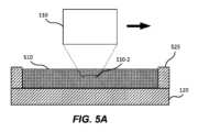
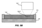
図5A~5Bは、光学画像化システム100の代替的な実施形態を示す図であり、対物レンズの遠位端110-2が、基板120の外表面120-1上に配置された流体510に浸されている。いくつかの実施形態では、図5Aを参照すると、基板は、基板の一領域を境界付ける(囲む)垂直壁525を備える。垂直壁525は、その領域内に流体510を保持するように構成されてもよい。流体は、対物レンズ110の遠位端110-2を所望の深さで浸漬するのに十分なレベルに維持されていてもよい。流体は、液滴310に関して上述した流体を含む、任意の適切な流体であってよい。いくつかの実施形態では、垂直壁525は、基板の一部であってもよい(例えば、基板にモールドされていてもよい)。代替的な実施形態では、垂直壁525は、基板の一部でなくてもよく、代わりに、基板上に延びる光学画像化システム100の筐体の一部であってもよく、それによって同じまたは類似の効果が得られる。 5A-5B illustrate an alternative embodiment of
これらの実施形態において、アクチュエータが基板120上の第1の場所(図5A)から第2の場所(図5B)に移動されるとき、遠位端110-2は流体中に浸されたままであってもよい。したがって、光線は、エアギャップを通らずに、流体を通って対物レンズ110と基板120の間を進むことができる。いくつかの実施形態では、対物レンズ110の遠位端110-2は、対物レンズが第1の場所から第2の場所に移動する際の乱流を低減するために平坦であってよい。上述したように、高スループットの画像化アプリケーションでは、対物レンズの高速な移動が必要となり得るが、これによって乱流が増幅される可能性がある。また、上述したように、乱流は、(例えば、望ましくない画像アーチファクトを生じさせ得る泡または流れの収差を形成することによって)画質に悪影響を及ぼし、及び/または、時間の経過とともに流体510の損失を引き起こす可能性がある。この乱流を低減することで、これらの問題に対処している。液滴を使用する光学画像化システム100の実施形態とは異なり、流体に浸漬された状態で対物レンズを移動させる実施形態では、凹状の遠位端110-2が問題を引き起こす可能性がある。これは、凹状の遠位端110-2を有する対物レンズ110の周りの流体510が、凹状の遠位端110-2に接触する流体510が曲率の異なる点に沿って異なる速度で流れ、非層流の状態で流れるような流れプロファイルを有するからである。この流れのパターンは、対物レンズ110の移動に伴って領域全体に伝播し、それによって過度な乱流が生じてしまう。これに対し、平坦な遠位端110-2によると、より層流が得られることで、そのような乱流を減少させ得る。 In these embodiments, distal end 110-2 may remain submerged in the fluid as the actuator is moved from a first location (FIG. 5A) to a second location (FIG. 5B) on
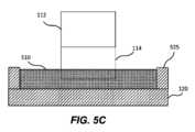
図5Cは、近位部分112及び遠位部分114を有する対物レンズ110の例示的な実施形態を示し、遠位部分114は、流体510中に浸漬された遠位端110-2を有する。このような実施形態では、遠位部分全体(または代替的に、流体510に浸漬されると予想される遠位部分の少なくとも一部)は、非テーパ(例えば、円筒形)であってもよい。これにより、対物レンズ110の移動する際に層流がさらに生じやすくなり、乱流を減少させることができる。 FIG. 5C shows an exemplary embodiment of
図5Dは、湾曲している垂直壁526を備える例示的な実施形態を示す。いくつかの実施形態では、垂直壁の内側(interior)は、図5A~5Cの垂直壁525のように、基板120の外表面120-1に対して垂直である。他の実施形態では、垂直壁の内側は、基板120の外表面120-1に対して垂直でなくてもよく、斜めに配置されてもよい。いくつかの実施形態では、垂直壁の内側は、図5A~5Cの垂直壁525のように平坦であってよい。他の実施形態では、垂直壁の内側は、図5Dの垂直壁526のように湾曲していてもよい。垂直壁の内側は、任意の適切なプロファイルに従って形成されてもよい。 FIG. 5D shows an exemplary embodiment with
いくつかの実施形態では、垂直壁525の高さは、垂直壁525によって境界付けられた(囲まれた)領域内に流体510を保持し、対物レンズ110が領域内を移動する際に流体510が飛び散る、あるいは他の方法でその領域から流出することを防止するのに十分な高さに最適化されてもよい。 In some embodiments, the height of
対物レンズ110が流体中に浸漬される実施形態(例えば、図5A~5Dに例示される実施形態)も、図4に例示されるものと類似のフィードバック制御ループを有していてもよい。そのような場合、液滴監視サブシステム及び液滴送達サブシステムは、それぞれ、流体監視サブシステム及び流体送達サブシステムに置き換えられてもよい。いくつかの実施形態では、流体監視サブシステムは、垂直壁525によって境界付けられた領域内の流体510のレベルが、対物レンズ110を浸漬するのに十分であることを連続的または周期的に判断してもよい。例えば、流体監視サブシステムは、流体レベルを光学的または電気的に監視し、流体510の重量を(例えば、基板120及び流体510の重量を測定する基板の下のスケールを用いて)監視し、または単に、光線が適切に屈折している(それによって、対物レンズ110がまだ流体510に浸されていることを示す)ことを確認するために対物レンズ110を介して取り込まれた画質を分析してもよい。別の例として、流体監視サブシステムは、光学センサを使用して流体中の気泡の存在を検出することにより、気泡が流体の蒸発を示し得ることから、ある量の流体が蒸発または領域から流出したかを判断してもよい。流体監視サブシステムは、気泡の量と、蒸発した流体の量とを相関させることができる。いくつかの実施形態では、流体監視サブシステムが、閾値量の流体が蒸発あるいは流出したと判断した場合(例えば、閾値数の気泡が検出されたことに基づいて、流体レベルライン(液面)が閾値量だけ低下したことが電気的または光学的に検出されたことに基づいて)、流体送達サブシステムがトリガー(作動)されて、失われた流体が自動的に補充されてもよい。例えば、流体送達サブシステムは、流体リザーバに連結された導管を備えてもよく、適切な量の置換流体が、任意の適切な手段(例えば、EWOD、ポンプによって生じる圧力差)によって領域に輸送されてもよい。 Embodiments in which
図5A~図5Dは、図1Aの簡略化された概略図の単一基板設計に関して上記の概念を示しているが(例えば、画像化された核酸配列は、基板120上または基板120の内部に配置されてもよい)、本開示は、同じ概念が、2つの基板が存在する図1Bの概略図に適用されることを意図していることに留意されたい。例えば、図1Bを参照すると、図5A~図5Dに従って画像化される核酸配列は、空間150内に配置(例えば、表面120-2または表面140-1に結合)されてもよい。 Note that although FIGS. 5A-5D illustrate the above concepts with respect to the single-substrate design of the simplified schematic of FIG. 1A (e.g., the nucleic acid sequences to be imaged may be located on or within substrate 120), the present disclosure contemplates that the same concepts apply to the schematic of FIG. 1B, where two substrates are present. For example, referring to FIG. 1B, nucleic acid sequences imaged according to FIGS. 5A-5D may be located within space 150 (eg, attached to surface 120-2 or surface 140-1).
図6は、核酸配列を配列決定するために基板を光学的に画像化するための例示的な方法600を示す。本方法は、ステップ610において、基板の外表面上に液滴を配置することを含んでもよい。基板は1つ以上の核酸配列を含み、基板の外表面は第1の材料を含む。ステップ620において、本方法は、対物レンズの遠位端が液滴と接触するように、基板の外表面上の第1の場所に対物レンズを位置付けることを含んでもよい。対物レンズの遠位端は第2の材料を含み、第2の材料は、液滴に対して、第1の材料よりも高い摩擦力を与えるように構成されている。ステップ630において、本方法は、対物レンズを基板の外表面上の第2の場所に移動させることを含んでもよい。対物レンズの移動は、第2の場所で対物レンズ及び基板の外表面が液滴との接触を保持するように、対物レンズの遠位端とともに液滴を移動させるように構成されている。 FIG. 6 shows an
特定の実施形態では、必要に応じて、図6の方法の1つ以上のステップを繰り返してもよい。本開示は、図6の方法の特定のステップが特定の順序で発生するものとして説明及び図示しているが、本開示は、図6の方法の任意の適切なステップが任意の適切な順序で発生することを意図している。さらに、本開示は、図6の方法の特定のステップを含む、基板上の核酸配列を配列決定するために基板を光学的に画像化するための例示的な方法を説明し、図示しているが、本開示は、基板上の核酸配列を配列決定するために基板を光学的に画像化する任意の適切な方法を意図しており、必要に応じて、図6の方法のステップの全て、一部を含んでもよいし、またはいずれも含まなくてもよい。さらに、本開示は、図6の方法の特定のステップを実施する特定の構成要素、デバイス、またはシステムを説明および図示するが、本開示は、図6の方法の任意の適切なステップを実施する任意の適切な構成要素、デバイス、またはシステムの任意の適切な組み合わせを意図するものである。 In particular embodiments, one or more steps of the method of FIG. 6 may be repeated as desired. Although this disclosure describes and illustrates certain steps of the method of FIG. 6 as occurring in a particular order, this disclosure contemplates any suitable steps of the method of FIG. 6 occurring in any suitable order. Further, although the present disclosure describes and illustrates an exemplary method for optically imaging a substrate for sequencing nucleic acid sequences on the substrate, including specific steps of the method of FIG. 6, the present disclosure contemplates any suitable method of optically imaging a substrate for sequencing nucleic acid sequences on the substrate, and may include all, some, or none of the steps of the method of FIG. 6, as appropriate. Furthermore, although this disclosure describes and illustrates particular components, devices, or systems for performing particular steps of the method of FIG. 6, this disclosure contemplates any suitable combination of any suitable components, devices, or systems for performing any suitable steps of the method of FIG.
図7は、基板上の核酸配列を配列決定(シーケンス)するために基板を光学的に画像化するための別の例示的な方法700を示す。本方法は、ステップ710において、基板の一領域内に流体を配置することを含んでもよい。その領域は垂直壁によって境界付けられており、基板は(例えば、基板における上記領域に対応する境界内の場所で)1つ以上の核酸配列を含む。ステップ720において、本方法は、対物レンズの遠位端が流体と接触するように、基板の外表面上の第1の場所に対物レンズを位置付けることを含んでもよい。ステップ730において、本方法は、対物レンズの遠位端を流体に浸したまま、対物レンズを基板の外表面上の第2の場所に移動させることを含んでもよい。 FIG. 7 shows another
特定の実施形態では、必要に応じて、図7の方法の1つ以上のステップを繰り返してもよい。本開示は、図7の方法の特定のステップが特定の順序で発生するものとして説明及び図示しているが、本開示は、図7の方法の任意の適切なステップが任意の適切な順序で発生することを意図している。さらに、本開示は、図7の方法の特定のステップを含む、基板上の核酸配列を配列決定するために基板を光学的に画像化するための例示的な方法を説明し、図示しているが、本開示は、基板上の核酸配列を配列決定するために基板を光学的に画像化する任意の適切な方法を意図しており、必要に応じて、図7の方法のステップの全て、一部を含んでもよいし、またはいずれも含まなくてもよい。さらに、本開示は、図6の方法の特定のステップを実施する特定の構成要素、デバイス、またはシステムを説明および図示するが、本開示は、図7の方法の任意の適切なステップを実施する任意の適切な構成要素、デバイス、またはシステムの任意の適切な組み合わせを意図するものである。 In particular embodiments, one or more steps of the method of FIG. 7 may be repeated as desired. Although this disclosure describes and illustrates certain steps of the method of FIG. 7 as occurring in a particular order, this disclosure contemplates any suitable steps of the method of FIG. 7 occurring in any suitable order. Moreover, although the present disclosure describes and illustrates an exemplary method for optically imaging a substrate for sequencing nucleic acid sequences on the substrate, including specific steps of the method of FIG. 7, the present disclosure contemplates any suitable method of optically imaging a substrate for sequencing nucleic acid sequences on the substrate, and may include all, some, or none of the steps of the method of FIG. 7, as appropriate. Furthermore, although this disclosure describes and illustrates particular components, devices, or systems for performing particular steps of the method of FIG. 6, this disclosure contemplates any suitable combination of any suitable components, devices, or systems for performing any suitable steps of the method of FIG.
本明細書に記載された例および実施形態は、例示のみを目的とし、それを考慮した様々な修正または変更は、当業者に示唆され、本願の趣旨および範囲に含まれ、添付の請求項の範囲に含まれるものと理解される。本明細書で引用したすべての刊行物、特許、および特許出願は、すべての目的のために、それらの全体が参照により本明細書に組み込まれる。 It is understood that the examples and embodiments described herein are for illustrative purposes only and that various modifications or changes in light thereof will be suggested to those skilled in the art and are within the spirit and scope of this application and within the scope of the appended claims. All publications, patents and patent applications cited herein are hereby incorporated by reference in their entirety for all purposes.
上記の説明は、例示的なものであり、制限的なものではないことが理解されるであろう。多くの実施形態は、上記の説明を検討すれば、当業者には明らかであろう。したがって、本発明の範囲は、上記の説明を参照して決定されるべきではなく、代わりに、その均等な全範囲と併せて、添付の特許請求の範囲を参照して決定されるべきである。 It will be understood that the above description is illustrative and not restrictive. Many embodiments will be apparent to those of skill in the art upon reviewing the above description. The scope of the invention should, therefore, be determined not with reference to the above description, but instead should be determined with reference to the appended claims, along with their full scope of equivalents.
前述の開示は本開示の例示的な態様を示しているが、添付の請求項によって定義される本開示の範囲から逸脱することなく、様々な変更および修正を行うことができる点に留意されたい。本明細書に記載された本開示の態様に従った方法の請求項の機能、ステップ及び/または動作は、任意の特定の順序で実行される必要はない。さらに、本開示の要素は単数形で記載または請求され得るが、単数形への限定が明示されない限り、複数形も意図される。 It should be noted that while the foregoing disclosure presents exemplary aspects of the present disclosure, various changes and modifications can be made without departing from the scope of the disclosure as defined by the appended claims. The functions, steps and/or actions of the method claims in accordance with the aspects of the disclosure described herein need not be performed in any particular order. Further, although elements of the disclosure may be described or claimed in the singular, the plural is also contemplated unless limitation to the singular is expressly stated.
Claims (44)
Translated fromJapaneseアクチュエータと、
基板を受けるように構成された取り付け要素と、
近位端および遠位端を有する対物レンズと、を備え、
前記基板は、前記基板の領域を境界付ける垂直壁を備え、前記垂直壁は、前記領域内に流体を保持するように構成され、前記基板は、1つ以上の核酸配列を有し、
前記対物レンズの前記近位端は、前記アクチュエータに連結され、前記対物レンズの前記遠位端は、前記基板の外表面の近くに位置するように構成され、前記対物レンズの前記遠位端は、前記流体に浸されるように構成されており、
前記アクチュエータは、前記対物レンズの前記遠位端を前記流体に浸したまま、前記基板の前記外表面の上の第1の場所から、前記基板の前記外表面の上の第2の場所に前記対物レンズを移動させるように構成されている、システム。An optical imaging system for nucleic acid sequencing, comprising:
an actuator;
a mounting element configured to receive the substrate;
an objective lens having a proximal end and a distal end;
said substrate comprising a vertical wall bounding a region of said substrate, said vertical wall configured to retain a fluid within said region, said substrate having one or more nucleic acid sequences;
the proximal end of the objective lens is coupled to the actuator, the distal end of the objective lens is configured to be located near an outer surface of the substrate, the distal end of the objective lens is configured to be immersed in the fluid;
wherein the actuator is configured to move the objective lens from a first location above the outer surface of the substrate to a second location above the outer surface of the substrate while the distal end of the objective lens is immersed in the fluid.
前記流体送達サブシステムは、前記流体監視サブシステムによる肯定的な判断時に、追加の流体を送達するように構成されている、請求項9に記載のシステム。further comprising a fluid monitoring subsystem for determining whether a portion of said fluid has evaporated from said region;
10. The system of Claim 9, wherein the fluid delivery subsystem is configured to deliver additional fluid upon a positive determination by the fluid monitoring subsystem.
前記領域から前記流体の一部が蒸発したかどうかを判断することは、前記流体中に閾値数の気泡が検出されるかどうかを判断することを含む、請求項10に記載のシステム。the fluid monitoring system comprising an optical sensor for detecting the presence of air bubbles in the fluid;
11. The system of claim 10, wherein determining whether a portion of the fluid has evaporated from the region includes determining whether a threshold number of air bubbles are detected in the fluid.
前記基板の領域内に流体を配置することであって、前記領域は、垂直壁によって境界付けられており、前記基板は、1つ以上の核酸配列を有する、流体を配置することと、
対物レンズの遠位端が前記液滴と接触するように、前記基板の外表面の上の第1の場所に前記対物レンズを位置付けることと、
前記対物レンズの前記遠位端を前記流体に浸したまま、前記対物レンズを前記基板の外表面の上の第2の場所に移動させることと、を含む方法。A method of optically imaging a substrate for nucleic acid sequencing, the method comprising:
disposing a fluid within a region of the substrate, the region bounded by vertical walls, the substrate having one or more nucleic acid sequences;
positioning the objective lens at a first location above the outer surface of the substrate such that a distal end of the objective lens contacts the droplet;
moving the objective lens to a second location above the outer surface of the substrate while the distal end of the objective lens remains immersed in the fluid.
前記判断に基づいて、流体送達サブシステムを介して追加の流体を送達することと、をさらに含む、請求項13に記載の方法。determining that a portion of the fluid has evaporated from the region;
14. The method of claim 13, further comprising delivering additional fluid via a fluid delivery subsystem based on the determination.
前記流体中の気泡の存在を検出することと、
閾値数の気泡が検出されたと判断することと、を含む、請求項21に記載の方法。Determining that a portion of the fluid has evaporated from the region includes:
detecting the presence of air bubbles in the fluid;
22. The method of claim 21, comprising determining that a threshold number of bubbles have been detected.
アクチュエータと、
基板を受けるように構成された取り付け要素と、
近位端および遠位端を有する対物レンズと、を備え、
前記基板は、1つ以上の核酸配列を含み、前記基板の外表面は、液滴を受けるように構成され、前記基板の前記外表面は第1の材料を含み、
前記対物レンズの前記近位端は前記アクチュエータに連結され、前記対物レンズの前記遠位端は前記基板の前記外表面の近くに位置するように構成され、前記対物レンズの前記遠位端は第2の材料を含み、前記第2の材料は、前記第1の材料よりも液滴に対して高い摩擦力を与えるように構成され、
前記アクチュエータは、前記対物レンズを前記基板の前記外表面上の第1の場所から前記基板の前記外表面上の第2の場所に移動させるように構成され、前記対物レンズを移動させることは、前記対物レンズおよび前記基板の前記外表面が前記第2の場所で前記液滴との接触を保持するように、前記対物レンズの前記遠位端とともに前記液滴を移動させるように構成されている、システム。An optical imaging system for nucleic acid sequencing, comprising:
an actuator;
a mounting element configured to receive the substrate;
an objective lens having a proximal end and a distal end;
said substrate comprising one or more nucleic acid sequences, said outer surface of said substrate being configured to receive a droplet, said outer surface of said substrate comprising a first material;
the proximal end of the objective lens is coupled to the actuator, the distal end of the objective lens is configured to be located near the outer surface of the substrate, the distal end of the objective lens comprises a second material, the second material configured to impart a higher frictional force to a droplet than the first material;
wherein the actuator is configured to move the objective lens from a first location on the outer surface of the substrate to a second location on the outer surface of the substrate, wherein moving the objective lens is configured to move the droplet along with the distal end of the objective lens such that the objective lens and the outer surface of the substrate maintain contact with the droplet at the second location.
前記液滴送達サブシステムは、前記液滴監視サブシステムによる否定的な判断時に、追加の液滴を送達するよう構成されている、請求項32に記載のシステム。further comprising a droplet monitoring subsystem for determining whether the objective lens and the outer surface of the substrate are in contact with the droplet;
33. The system of Claim 32, wherein the droplet delivery subsystem is configured to deliver additional droplets upon a negative determination by the droplet monitoring subsystem.
前記基板の外表面に液滴を配置することであって、前記基板は、1つ以上の核酸配列を有し、前記基板の前記外表面は第1の材料を含む、液滴を配置することと、
対物レンズの遠位端が液滴と接触するように、前記基板の前記外表面の上の第1の場所に前記対物レンズを位置付けることであって、前記対物レンズの前記遠位端は第2の材料を含み、前記第2の材料は、前記第1の材料よりも液滴に対して高い摩擦力を与えるように構成されている、対物レンズを位置付けることと、
前記対物レンズを前記基板の前記外表面上の第2の場所に移動させることと、を含み、
前記対物レンズを移動させることは、前記対物レンズおよび前記基板の前記外表面が前記第2の場所で前記液滴との接触を保持するように、前記対物レンズの前記遠位端とともに前記液滴を移動させるように構成されている、方法。A method of optically imaging a substrate for nucleic acid sequencing, the method comprising:
disposing a droplet on an outer surface of the substrate, the substrate having one or more nucleic acid sequences, the outer surface of the substrate comprising a first material;
positioning the objective lens at a first location on the outer surface of the substrate such that a distal end of the objective lens contacts a droplet, the distal end of the objective lens comprising a second material, the second material configured to impart a higher frictional force to the droplet than the first material;
moving the objective lens to a second location on the outer surface of the substrate;
wherein moving the objective lens is configured to move the droplet with the distal end of the objective lens such that the objective lens and the outer surface of the substrate retain contact with the droplet at the second location.
前記判断に基づいて、液滴送達サブシステムを介して、追加の液滴を送達することと、
をさらに含む、請求項37に記載の方法。determining that the objective lens and the outer surface of the substrate are not in contact with the droplet;
delivering additional droplets via the droplet delivery subsystem based on the determination;
38. The method of claim 37, further comprising:
Priority Applications (1)
| Application Number | Priority Date | Filing Date | Title |
|---|---|---|---|
| JP2025024721AJP2025090602A (en) | 2020-06-29 | 2025-02-19 | Systems and methods for optical scanning and imaging through fluid media for nucleic acid sequencing - Patents.com |
Applications Claiming Priority (3)
| Application Number | Priority Date | Filing Date | Title |
|---|---|---|---|
| US202063045566P | 2020-06-29 | 2020-06-29 | |
| US63/045,566 | 2020-06-29 | ||
| PCT/CN2021/101994WO2022001804A1 (en) | 2020-06-29 | 2021-06-24 | Systems and methods for optical scanning and imaging through a fluid medium for nucleic acid sequencing |
Related Child Applications (1)
| Application Number | Title | Priority Date | Filing Date |
|---|---|---|---|
| JP2025024721ADivisionJP2025090602A (en) | 2020-06-29 | 2025-02-19 | Systems and methods for optical scanning and imaging through fluid media for nucleic acid sequencing - Patents.com |
Publications (3)
| Publication Number | Publication Date |
|---|---|
| JP2023531253Atrue JP2023531253A (en) | 2023-07-21 |
| JPWO2022001804A5 JPWO2022001804A5 (en) | 2024-06-10 |
| JP7639029B2 JP7639029B2 (en) | 2025-03-04 |
Family
ID=79031829
Family Applications (2)
| Application Number | Title | Priority Date | Filing Date |
|---|---|---|---|
| JP2022580106AActiveJP7639029B2 (en) | 2020-06-29 | 2021-06-24 | Systems and methods for optical scanning and imaging through fluid media for nucleic acid sequencing - Patents.com |
| JP2025024721APendingJP2025090602A (en) | 2020-06-29 | 2025-02-19 | Systems and methods for optical scanning and imaging through fluid media for nucleic acid sequencing - Patents.com |
Family Applications After (1)
| Application Number | Title | Priority Date | Filing Date |
|---|---|---|---|
| JP2025024721APendingJP2025090602A (en) | 2020-06-29 | 2025-02-19 | Systems and methods for optical scanning and imaging through fluid media for nucleic acid sequencing - Patents.com |
Country Status (8)
| Country | Link |
|---|---|
| US (2) | US12013521B2 (en) |
| EP (1) | EP4172620A4 (en) |
| JP (2) | JP7639029B2 (en) |
| KR (1) | KR20230028539A (en) |
| CN (1) | CN116134149A (en) |
| AU (1) | AU2021298561A1 (en) |
| CA (1) | CA3186498A1 (en) |
| WO (1) | WO2022001804A1 (en) |
Families Citing this family (2)
| Publication number | Priority date | Publication date | Assignee | Title |
|---|---|---|---|---|
| WO2025117061A1 (en)* | 2023-11-30 | 2025-06-05 | Agilent Technologies, Inc. | System and method for water immersion objective bubble detection |
| WO2025188823A1 (en)* | 2024-03-07 | 2025-09-12 | Illumina, Inc. | Immersion microscopy arrangement for sequencing system with rapid scanning |
Citations (6)
| Publication number | Priority date | Publication date | Assignee | Title |
|---|---|---|---|---|
| JP2005083800A (en)* | 2003-09-05 | 2005-03-31 | Hitachi Ltd | Defect inspection method and defect inspection apparatus |
| JP2010039374A (en)* | 2008-08-07 | 2010-02-18 | Olympus Corp | Confocal scanning type microscope device |
| JP2019501635A (en)* | 2015-11-03 | 2019-01-24 | プレジデント アンド フェローズ オブ ハーバード カレッジ | Methods and apparatus for stereoscopic imaging of three-dimensional nucleic acid containing matrices |
| WO2019131947A1 (en)* | 2017-12-27 | 2019-07-04 | 国立研究開発法人理化学研究所 | Spectroscopic analysis device, spectroscopic analysis method, program, recording medium, and microscope |
| US20210382288A1 (en)* | 2018-10-24 | 2021-12-09 | Carl Zeiss Microscopy Gmbh | Apparatus and method for applying a liquid immersion medium into a clearance between a microscope objective and a specimen to be examined under the microscope |
| JP2022513737A (en)* | 2018-12-07 | 2022-02-09 | ウルティマ・ゲノミクス・インコーポレーテッド | Implementation barrier for controlled environment during sample processing and sample detection |
Family Cites Families (33)
| Publication number | Priority date | Publication date | Assignee | Title |
|---|---|---|---|---|
| US4346164A (en)* | 1980-10-06 | 1982-08-24 | Werner Tabarelli | Photolithographic method for the manufacture of integrated circuits |
| DK0679251T3 (en) | 1993-01-18 | 1999-01-25 | Evotec Biosystems Aktiengesell | Process and apparatus for assessing the fitness of biopolymers |
| US5776674A (en) | 1995-06-05 | 1998-07-07 | Seq, Ltd | Chemical biochemical and biological processing in thin films |
| US6503711B1 (en)* | 1997-06-18 | 2003-01-07 | Ulrich J. Krull | Nucleic acid biosensor diagnostics |
| EP0978251B1 (en)* | 1998-08-07 | 2005-01-26 | Olympus Corporation | Endoscope capable of being autoclaved |
| US6995930B2 (en)* | 1999-12-29 | 2006-02-07 | Carl Zeiss Smt Ag | Catadioptric projection objective with geometric beam splitting |
| US6870610B1 (en)* | 2002-05-07 | 2005-03-22 | Dcs Corporation | Method and apparatus for detecting defects in a material in a liquid bath |
| US7130037B1 (en)* | 2003-01-09 | 2006-10-31 | Kla-Tencor Technologies Corp. | Systems for inspecting wafers and reticles with increased resolution |
| US20050227358A1 (en) | 2004-04-01 | 2005-10-13 | Mcentee John F | Methods of determining a quality of an array substrate |
| WO2005104110A1 (en)* | 2004-04-22 | 2005-11-03 | Matsushita Electric Industrial Co., Ltd. | Optical head device and optical information device |
| EP1852745A1 (en)* | 2006-05-05 | 2007-11-07 | Carl Zeiss SMT AG | High-NA projection objective |
| WO2009018911A1 (en)* | 2007-08-03 | 2009-02-12 | Carl Zeiss Smt Ag | Projection objective for microlithography, projection exposure apparatus, projection exposure method and optical correction plate |
| US20090109416A1 (en) | 2007-09-13 | 2009-04-30 | Applied Precision, Inc. | Dispersing immersion liquid for high resolution imaging and lithography |
| EP4325209A3 (en)* | 2008-09-16 | 2024-05-01 | Pacific Biosciences Of California, Inc. | Integrated optical device |
| US20110081664A1 (en)* | 2008-10-17 | 2011-04-07 | University Of Massachusetts | Multipurpose microfluidic device for mimicking a microenvironment within a tumor |
| WO2010047396A1 (en)* | 2008-10-24 | 2010-04-29 | オリンパスメディカルシステムズ株式会社 | Insertion section of endoscope |
| WO2011103143A1 (en)* | 2010-02-16 | 2011-08-25 | The University Of North Carolina At Chapel Hill | Array of micromolded structures for sorting adherent cells |
| EP2581028B1 (en)* | 2010-11-09 | 2015-03-04 | Olympus Medical Systems Corp. | Image pickup apparatus for endoscope |
| JP6210656B2 (en)* | 2011-06-08 | 2017-10-11 | オリンパス株式会社 | Imaging device |
| US9494505B2 (en)* | 2012-10-29 | 2016-11-15 | The Regents Of The University Of California | Scanning non-contact surface microrheometer |
| US9624540B2 (en)* | 2013-02-22 | 2017-04-18 | Pacific Biosciences Of California, Inc. | Integrated illumination of optical analytical devices |
| WO2014180684A1 (en)* | 2013-05-07 | 2014-11-13 | Asml Netherlands B.V. | Alignment sensor, lithographic apparatus and alignment method |
| US20150064057A1 (en)* | 2013-08-29 | 2015-03-05 | The Regents Of The University Of California | Methods for producing nio nanoparticle thin films and patterning ofni conductors by nio reductive sintering and laser ablation |
| US9362715B2 (en)* | 2014-02-10 | 2016-06-07 | Soraa Laser Diode, Inc | Method for manufacturing gallium and nitrogen bearing laser devices with improved usage of substrate material |
| EP3037031A4 (en)* | 2013-12-18 | 2017-05-17 | Olympus Corporation | Endoscope and endoscope system |
| WO2015159973A1 (en)* | 2014-04-18 | 2015-10-22 | 株式会社荏原製作所 | Substrate processing device, substrate processing system, and substrate processing method |
| US10365434B2 (en)* | 2015-06-12 | 2019-07-30 | Pacific Biosciences Of California, Inc. | Integrated target waveguide devices and systems for optical coupling |
| GB2551122A (en)* | 2016-06-02 | 2017-12-13 | Univ Southampton | Fluid flow device and method for making the same |
| US11247462B2 (en)* | 2017-04-03 | 2022-02-15 | Board Of Trustees Of The University Of Arkansas | Selective resistive sintering—a new additive manufacturing method |
| CN114643087A (en)* | 2017-04-26 | 2022-06-21 | 伯克利之光生命科技公司 | Biological treatment system and method using microfluidic devices with optimized electrowetting surfaces |
| US11499962B2 (en)* | 2017-11-17 | 2022-11-15 | Ultima Genomics, Inc. | Methods and systems for analyte detection and analysis |
| WO2020064290A1 (en)* | 2018-09-27 | 2020-04-02 | Asml Netherlands B.V. | Apparatus and method for measuring a position of a mark |
| KR102848805B1 (en)* | 2019-07-31 | 2025-08-22 | 삼성전자주식회사 | method for inspecting Extreme Ultraviolet light reticle, reticle manufacturing method and manufacturing method of semiconductor device including the same |
- 2021
- 2021-06-22USUS17/353,901patent/US12013521B2/enactiveActive
- 2021-06-24KRKR1020237003239Apatent/KR20230028539A/enactivePending
- 2021-06-24CNCN202180046346.3Apatent/CN116134149A/enactivePending
- 2021-06-24WOPCT/CN2021/101994patent/WO2022001804A1/ennot_activeCeased
- 2021-06-24CACA3186498Apatent/CA3186498A1/enactivePending
- 2021-06-24EPEP21831556.2Apatent/EP4172620A4/enactivePending
- 2021-06-24AUAU2021298561Apatent/AU2021298561A1/enactivePending
- 2021-06-24JPJP2022580106Apatent/JP7639029B2/enactiveActive
- 2024
- 2024-03-11USUS18/601,187patent/US20240210669A1/enactivePending
- 2025
- 2025-02-19JPJP2025024721Apatent/JP2025090602A/enactivePending
Patent Citations (6)
| Publication number | Priority date | Publication date | Assignee | Title |
|---|---|---|---|---|
| JP2005083800A (en)* | 2003-09-05 | 2005-03-31 | Hitachi Ltd | Defect inspection method and defect inspection apparatus |
| JP2010039374A (en)* | 2008-08-07 | 2010-02-18 | Olympus Corp | Confocal scanning type microscope device |
| JP2019501635A (en)* | 2015-11-03 | 2019-01-24 | プレジデント アンド フェローズ オブ ハーバード カレッジ | Methods and apparatus for stereoscopic imaging of three-dimensional nucleic acid containing matrices |
| WO2019131947A1 (en)* | 2017-12-27 | 2019-07-04 | 国立研究開発法人理化学研究所 | Spectroscopic analysis device, spectroscopic analysis method, program, recording medium, and microscope |
| US20210382288A1 (en)* | 2018-10-24 | 2021-12-09 | Carl Zeiss Microscopy Gmbh | Apparatus and method for applying a liquid immersion medium into a clearance between a microscope objective and a specimen to be examined under the microscope |
| JP2022513737A (en)* | 2018-12-07 | 2022-02-09 | ウルティマ・ゲノミクス・インコーポレーテッド | Implementation barrier for controlled environment during sample processing and sample detection |
Also Published As
| Publication number | Publication date |
|---|---|
| JP2025090602A (en) | 2025-06-17 |
| EP4172620A4 (en) | 2024-10-09 |
| EP4172620A1 (en) | 2023-05-03 |
| JP7639029B2 (en) | 2025-03-04 |
| US12013521B2 (en) | 2024-06-18 |
| WO2022001804A1 (en) | 2022-01-06 |
| US20210405337A1 (en) | 2021-12-30 |
| US20240210669A1 (en) | 2024-06-27 |
| KR20230028539A (en) | 2023-02-28 |
| AU2021298561A1 (en) | 2023-01-19 |
| CN116134149A (en) | 2023-05-16 |
| CA3186498A1 (en) | 2022-01-06 |
Similar Documents
| Publication | Publication Date | Title |
|---|---|---|
| US20240210669A1 (en) | Systems and methods for optical scanning and imaging through a fluid medium for nucleic acid sequencing | |
| US11542554B2 (en) | Method and apparatus for volumetric imaging | |
| JP7620549B2 (en) | Implementation barrier for controlled environment during sample processing and sample detection | |
| Lindken et al. | Micro-particle image velocimetry (µPIV): recent developments, applications, and guidelines | |
| Deutsch et al. | A novel miniature cell retainer for correlative high-content analysis of individual untethered non-adherent cells | |
| WO2010111231A1 (en) | Manipulation of microfluidic droplets | |
| US8945944B2 (en) | Device and method for quantitatively determining an analyte, a method for determining an effective size of a molecule, a method for attaching molecules to a substrate, and a device for detecting molecules | |
| US20240302378A1 (en) | Methods of Microfluidic Assay and Bioproduction from Non-Mammalian Cells and Kits Therefor | |
| Molino et al. | On-chip quantitative measurement of mechanical stresses during cell migration with emulsion droplets | |
| Zadeh et al. | An experimental study on the mobility of droplets in liquid-liquid Taylor flows within circular capillaries | |
| Deroy et al. | Assaying macrophage chemotaxis using fluid‐walled microfluidics | |
| US20240318120A1 (en) | Apparatuses, methods, and kits for microfluidic assays | |
| US20240151582A1 (en) | Immersion imaging systems and methods for flowcells | |
| EP3957977B1 (en) | Fluidic apparatus for optical interrogation of individual microorganisms | |
| Cohen et al. | In Honor of WE Moerner: Confining Molecules for Single‐Molecule Spectroscopy | |
| Huang | Development and applications of light field microscopy systems for on-chip 3D characterization of dynamic samples in microfluidic platforms | |
| KR20240142546A (en) | Devices and methods performed for examining and/or processing specific biological or medical samples | |
| JP2025533369A (en) | Dynamic Optical System Calibration | |
| Elius | Study of bacteria super-hydrophobic wall interactions for novel anti-biofouling materials: a thesis in Mechanical Engineering | |
| Lerner et al. | Fretsael microscopy—localizing biomolecular interactions at nanometer accuracy using confocal microscopy and simple dyes | |
| Esfahani | Three-dimensional cancer cell migration under mechanochemical guidance | |
| WO2025059293A1 (en) | Methods and compositions for assessing the performance of instruments adapted for single-molecule tracking | |
| Yue et al. | Enhanced bacterial chemotaxis in confined microchannels: Optimal performance in lane widths matching circular swimming radius | |
| De Angelis et al. | Dynamic single particle measurements with a compact, high throughput iSCAT-TIRF setup |
Legal Events
| Date | Code | Title | Description |
|---|---|---|---|
| A521 | Request for written amendment filed | Free format text:JAPANESE INTERMEDIATE CODE: A523 Effective date:20230303 | |
| A521 | Request for written amendment filed | Free format text:JAPANESE INTERMEDIATE CODE: A523 Effective date:20240531 | |
| A621 | Written request for application examination | Free format text:JAPANESE INTERMEDIATE CODE: A621 Effective date:20240531 | |
| A977 | Report on retrieval | Free format text:JAPANESE INTERMEDIATE CODE: A971007 Effective date:20250122 | |
| TRDD | Decision of grant or rejection written | ||
| A01 | Written decision to grant a patent or to grant a registration (utility model) | Free format text:JAPANESE INTERMEDIATE CODE: A01 Effective date:20250128 | |
| A61 | First payment of annual fees (during grant procedure) | Free format text:JAPANESE INTERMEDIATE CODE: A61 Effective date:20250219 | |
| R150 | Certificate of patent or registration of utility model | Ref document number:7639029 Country of ref document:JP Free format text:JAPANESE INTERMEDIATE CODE: R150 |