JP2023528388A - Tubing system including anti-reassembly mechanism - Google Patents
Tubing system including anti-reassembly mechanismDownload PDFInfo
- Publication number
- JP2023528388A JP2023528388AJP2022573492AJP2022573492AJP2023528388AJP 2023528388 AJP2023528388 AJP 2023528388AJP 2022573492 AJP2022573492 AJP 2022573492AJP 2022573492 AJP2022573492 AJP 2022573492AJP 2023528388 AJP2023528388 AJP 2023528388A
- Authority
- JP
- Japan
- Prior art keywords
- module
- locking
- valve
- tube connector
- connector system
- Prior art date
- Legal status (The legal status is an assumption and is not a legal conclusion. Google has not performed a legal analysis and makes no representation as to the accuracy of the status listed.)
- Pending
Links
Images


Classifications
- F—MECHANICAL ENGINEERING; LIGHTING; HEATING; WEAPONS; BLASTING
- F16—ENGINEERING ELEMENTS AND UNITS; GENERAL MEASURES FOR PRODUCING AND MAINTAINING EFFECTIVE FUNCTIONING OF MACHINES OR INSTALLATIONS; THERMAL INSULATION IN GENERAL
- F16L—PIPES; JOINTS OR FITTINGS FOR PIPES; SUPPORTS FOR PIPES, CABLES OR PROTECTIVE TUBING; MEANS FOR THERMAL INSULATION IN GENERAL
- F16L37/00—Couplings of the quick-acting type
- F16L37/28—Couplings of the quick-acting type with fluid cut-off means
- F16L37/30—Couplings of the quick-acting type with fluid cut-off means with fluid cut-off means in each of two pipe-end fittings
- F16L37/367—Couplings of the quick-acting type with fluid cut-off means with fluid cut-off means in each of two pipe-end fittings with two gate valves or sliding valves
- A—HUMAN NECESSITIES
- A61—MEDICAL OR VETERINARY SCIENCE; HYGIENE
- A61M—DEVICES FOR INTRODUCING MEDIA INTO, OR ONTO, THE BODY; DEVICES FOR TRANSDUCING BODY MEDIA OR FOR TAKING MEDIA FROM THE BODY; DEVICES FOR PRODUCING OR ENDING SLEEP OR STUPOR
- A61M5/00—Devices for bringing media into the body in a subcutaneous, intra-vascular or intramuscular way; Accessories therefor, e.g. filling or cleaning devices, arm-rests
- A61M5/50—Devices for bringing media into the body in a subcutaneous, intra-vascular or intramuscular way; Accessories therefor, e.g. filling or cleaning devices, arm-rests having means for preventing re-use, or for indicating if defective, used, tampered with or unsterile
- A—HUMAN NECESSITIES
- A61—MEDICAL OR VETERINARY SCIENCE; HYGIENE
- A61M—DEVICES FOR INTRODUCING MEDIA INTO, OR ONTO, THE BODY; DEVICES FOR TRANSDUCING BODY MEDIA OR FOR TAKING MEDIA FROM THE BODY; DEVICES FOR PRODUCING OR ENDING SLEEP OR STUPOR
- A61M39/00—Tubes, tube connectors, tube couplings, valves, access sites or the like, specially adapted for medical use
- A61M39/10—Tube connectors; Tube couplings
- A61M39/1011—Locking means for securing connection; Additional tamper safeties
- A—HUMAN NECESSITIES
- A61—MEDICAL OR VETERINARY SCIENCE; HYGIENE
- A61M—DEVICES FOR INTRODUCING MEDIA INTO, OR ONTO, THE BODY; DEVICES FOR TRANSDUCING BODY MEDIA OR FOR TAKING MEDIA FROM THE BODY; DEVICES FOR PRODUCING OR ENDING SLEEP OR STUPOR
- A61M39/00—Tubes, tube connectors, tube couplings, valves, access sites or the like, specially adapted for medical use
- A61M39/10—Tube connectors; Tube couplings
- A61M39/16—Tube connectors; Tube couplings having provision for disinfection or sterilisation
- A61M39/165—Shrouds or protectors for aseptically enclosing the connector
- A—HUMAN NECESSITIES
- A61—MEDICAL OR VETERINARY SCIENCE; HYGIENE
- A61M—DEVICES FOR INTRODUCING MEDIA INTO, OR ONTO, THE BODY; DEVICES FOR TRANSDUCING BODY MEDIA OR FOR TAKING MEDIA FROM THE BODY; DEVICES FOR PRODUCING OR ENDING SLEEP OR STUPOR
- A61M39/00—Tubes, tube connectors, tube couplings, valves, access sites or the like, specially adapted for medical use
- A61M39/22—Valves or arrangement of valves
- A61M39/26—Valves closing automatically on disconnecting the line and opening on reconnection thereof
- F—MECHANICAL ENGINEERING; LIGHTING; HEATING; WEAPONS; BLASTING
- F16—ENGINEERING ELEMENTS AND UNITS; GENERAL MEASURES FOR PRODUCING AND MAINTAINING EFFECTIVE FUNCTIONING OF MACHINES OR INSTALLATIONS; THERMAL INSULATION IN GENERAL
- F16L—PIPES; JOINTS OR FITTINGS FOR PIPES; SUPPORTS FOR PIPES, CABLES OR PROTECTIVE TUBING; MEANS FOR THERMAL INSULATION IN GENERAL
- F16L37/00—Couplings of the quick-acting type
- F16L37/08—Couplings of the quick-acting type in which the connection between abutting or axially overlapping ends is maintained by locking members
- F16L37/084—Couplings of the quick-acting type in which the connection between abutting or axially overlapping ends is maintained by locking members combined with automatic locking
- F16L37/091—Couplings of the quick-acting type in which the connection between abutting or axially overlapping ends is maintained by locking members combined with automatic locking by means of a ring provided with teeth or fingers
- A—HUMAN NECESSITIES
- A61—MEDICAL OR VETERINARY SCIENCE; HYGIENE
- A61M—DEVICES FOR INTRODUCING MEDIA INTO, OR ONTO, THE BODY; DEVICES FOR TRANSDUCING BODY MEDIA OR FOR TAKING MEDIA FROM THE BODY; DEVICES FOR PRODUCING OR ENDING SLEEP OR STUPOR
- A61M39/00—Tubes, tube connectors, tube couplings, valves, access sites or the like, specially adapted for medical use
- A61M39/10—Tube connectors; Tube couplings
- A61M2039/1033—Swivel nut connectors, e.g. threaded connectors, bayonet-connectors
- A—HUMAN NECESSITIES
- A61—MEDICAL OR VETERINARY SCIENCE; HYGIENE
- A61M—DEVICES FOR INTRODUCING MEDIA INTO, OR ONTO, THE BODY; DEVICES FOR TRANSDUCING BODY MEDIA OR FOR TAKING MEDIA FROM THE BODY; DEVICES FOR PRODUCING OR ENDING SLEEP OR STUPOR
- A61M39/00—Tubes, tube connectors, tube couplings, valves, access sites or the like, specially adapted for medical use
- A61M39/10—Tube connectors; Tube couplings
- A61M2039/1072—Tube connectors; Tube couplings with a septum present in the connector
- A—HUMAN NECESSITIES
- A61—MEDICAL OR VETERINARY SCIENCE; HYGIENE
- A61M—DEVICES FOR INTRODUCING MEDIA INTO, OR ONTO, THE BODY; DEVICES FOR TRANSDUCING BODY MEDIA OR FOR TAKING MEDIA FROM THE BODY; DEVICES FOR PRODUCING OR ENDING SLEEP OR STUPOR
- A61M39/00—Tubes, tube connectors, tube couplings, valves, access sites or the like, specially adapted for medical use
- A61M39/10—Tube connectors; Tube couplings
- A61M2039/1077—Adapters, e.g. couplings adapting a connector to one or several other connectors
- A—HUMAN NECESSITIES
- A61—MEDICAL OR VETERINARY SCIENCE; HYGIENE
- A61M—DEVICES FOR INTRODUCING MEDIA INTO, OR ONTO, THE BODY; DEVICES FOR TRANSDUCING BODY MEDIA OR FOR TAKING MEDIA FROM THE BODY; DEVICES FOR PRODUCING OR ENDING SLEEP OR STUPOR
- A61M39/00—Tubes, tube connectors, tube couplings, valves, access sites or the like, specially adapted for medical use
- A61M39/22—Valves or arrangement of valves
- A61M39/24—Check- or non-return valves
- A61M2039/2433—Valve comprising a resilient or deformable element, e.g. flap valve, deformable disc
- A—HUMAN NECESSITIES
- A61—MEDICAL OR VETERINARY SCIENCE; HYGIENE
- A61M—DEVICES FOR INTRODUCING MEDIA INTO, OR ONTO, THE BODY; DEVICES FOR TRANSDUCING BODY MEDIA OR FOR TAKING MEDIA FROM THE BODY; DEVICES FOR PRODUCING OR ENDING SLEEP OR STUPOR
- A61M39/00—Tubes, tube connectors, tube couplings, valves, access sites or the like, specially adapted for medical use
- A61M39/22—Valves or arrangement of valves
- A61M39/26—Valves closing automatically on disconnecting the line and opening on reconnection thereof
- A61M2039/267—Valves closing automatically on disconnecting the line and opening on reconnection thereof having a sealing sleeve around a tubular or solid stem portion of the connector
- A—HUMAN NECESSITIES
- A61—MEDICAL OR VETERINARY SCIENCE; HYGIENE
- A61M—DEVICES FOR INTRODUCING MEDIA INTO, OR ONTO, THE BODY; DEVICES FOR TRANSDUCING BODY MEDIA OR FOR TAKING MEDIA FROM THE BODY; DEVICES FOR PRODUCING OR ENDING SLEEP OR STUPOR
- A61M2205/00—General characteristics of the apparatus
- A61M2205/27—General characteristics of the apparatus preventing use
- A61M2205/273—General characteristics of the apparatus preventing use preventing reuse, e.g. of disposables
Landscapes
- Health & Medical Sciences (AREA)
- Heart & Thoracic Surgery (AREA)
- Engineering & Computer Science (AREA)
- Life Sciences & Earth Sciences (AREA)
- General Health & Medical Sciences (AREA)
- Anesthesiology (AREA)
- Biomedical Technology (AREA)
- Hematology (AREA)
- Veterinary Medicine (AREA)
- Animal Behavior & Ethology (AREA)
- Public Health (AREA)
- Pulmonology (AREA)
- General Engineering & Computer Science (AREA)
- Mechanical Engineering (AREA)
- Epidemiology (AREA)
- Vascular Medicine (AREA)
- Infusion, Injection, And Reservoir Apparatuses (AREA)
Abstract
Translated fromJapaneseDescription
Translated fromJapanese本出願は、2020年5月30日に出願された米国仮特許出願番号第63/032,609、名称「Tubing System with Reassembly Prevention Mechanism」の利益を主張するものであり、参照することにより全体が本明細書に援用される。 This application claims the benefit of U.S. Provisional Patent Application No. 63/032,609, entitled "Tubing System with Reassembled Prevention Mechanism," filed May 30, 2020, and is incorporated by reference in its entirety. incorporated herein by reference.
本発明は医療用アクセスデバイスに関し、より具体的には、医療用チューブの非接続システムに関する。 The present invention relates to medical access devices and, more particularly, to a disconnect system for medical tubing.
静脈内カテーテル、栄養チューブ、尿道カテーテル、胸腔チューブ、及び様々な外科用ドレーンを含む医療用アクセスデバイスが、様々な目的で入院する患者の治療に使用される。これらの医療用アクセスデバイスの多くは患者に対して、又は患者からの流体を輸送し、及び、治療中、患者に対して可動範囲を提供するように、様々な可撓性チューブを使用する。残念なことに、患者が示す運動の自由度により、医療用アクセスデバイスに関連するチューブに、チューブ、患者、又はその両方に損傷を及ぼす力がかかることがよくある。例えば、静脈内輸液の投与で一般的に使用されるチューブは、数フィートの長さであることが多く、したがって、病院のベッド、又は患者周辺の他の医療機器に絡まることがある。患者が動くと、チューブが引っ張られ、外れることがある。極端なケースでは、患者に投与されている流体、又は患者自身の体液が漏れることがあり、患者の治療環境が汚染されるリスクを生み出し、患者を感染リスクにさらす可能性がある。 Medical access devices, including intravenous catheters, feeding tubes, urinary catheters, chest tubes, and various surgical drains, are used to treat hospitalized patients for a variety of purposes. Many of these medical access devices use various flexible tubes to transport fluids to and from the patient and to provide a range of motion for the patient during treatment. Unfortunately, the freedom of movement exhibited by the patient often places forces on the tubing associated with the medical access device that are damaging to the tubing, the patient, or both. For example, tubes commonly used in the administration of intravenous fluids are often several feet long and thus can become entangled in hospital beds or other medical equipment around the patient. When the patient moves, the tube may be pulled and dislodged. In extreme cases, fluids being administered to the patient or the patient's own bodily fluids may leak, creating a risk of contamination of the patient's treatment environment and potentially exposing the patient to infection risk.
これらの懸念を軽減するために、十分な張力がかかると「壊れて外れる(分離する)」ように設計された、多くの異なるチューブコネクタ及びアダプタが開発されてきた。いくつかのケースでは、これらのコネクタは、流体が、別のコネクタを通過することを防止する内部バルブを含む。これらの製品は別のアダプタからの漏出を最小化する際には効果的であることが多いものの、これらの従来技術のコネクタは、患者又は介護者がチューブアダプタを再接続しようと試みた場合には、汚染リスクが存在する。チューブアダプタが外れ、非滅菌の環境に曝露されると、アダプタの再組立(リアセンブリ、reassembly)は、患者の感染の可能性を高めうる顕著な汚染リスクとなる。したがって、分離されたアダプタの再接続に伴う汚染及び感染リスクを最小化しながら、耐漏出性(leak resistant)の、分離される設計の利益をもたらす、改良されたチューブアダプタが求められている。本実施の形態は、これらの先行技術における欠点や他の欠点に向けられたものである。 To alleviate these concerns, many different tube connectors and adapters have been developed that are designed to "break apart" when subjected to sufficient tension. In some cases, these connectors include internal valves that prevent fluid from passing through another connector. While these products are often effective in minimizing leakage from another adapter, these prior art connectors do not work if the patient or caregiver attempts to reconnect the tube adapter. there is a contamination risk. Once the tubing adapter is disconnected and exposed to a non-sterile environment, reassembly of the adapter poses a significant contamination risk that can increase the likelihood of patient infection. Accordingly, there is a need for an improved tube adapter that provides the benefits of a leak resistant, detachable design while minimizing the contamination and infection risks associated with reconnecting detached adapters. The present embodiments address these and other shortcomings in the prior art.
図1は、2つの医療用チューブを接続するように構成されたチューブコネクタシステム100の実施形態を示している。チューブコネクタシステム100は、第1のチューブアダプタ102、第2のチューブアダプタ104、及び第1のチューブアダプタ102と第2のチューブアダプタ104との間の中央コネクタ106を備える。全般に、チューブコネクタシステム100は、患者と、上流の流体源(例えば、輸液バッグ)又は下流の流体容器(例えば、ドレーン又は尿道カテーテル)のいずれかの間で接続される、2つの長さの医療用チューブの間の使い捨ての分離機構として使用されるように設計されている。チューブコネクタシステム100は、医療用溶液の上流用バッグを、静脈ラインを通って患者に接続する際の使用に極めて適していることを理解されたい。いくつかの実施形態では、第1のチューブアダプタ102及び第2のチューブアダプタ104は、第1のチューブアダプタ102及び第2のチューブアダプタ104に対して中央コネクタ106が回転可能な方法で、中央コネクタ106に取り付けられる。 FIG. 1 shows an embodiment of a
本発明で使用されているように、全般に、チューブコネクタシステム100は円筒形であり、第1のチューブアダプタ102及び第2のチューブアダプタ104の間の中央コネクタ102の中央を通って延びる長手方向軸に関して対称的であることが理解されるであろう。「長手方向」についての言及は、チューブコネクタシステム100を通って延びる中央長手方向軸と平行又は共線である方向又は軸を指す。半径方向又は半径方向軸についての言及は、中央長手方向軸に実質的に直交する方向であると理解されるであろう。回転運動又は回転方向についての言及は、(別の軸又は回転が特定されていない限り)長手方向軸周囲の時計回り又は反時計回りの運動についての言及であると理解されるであろう。チューブコネクタシステム100内の機構を説明するとき、内部機構又は内向き方向についての言及は、中央コネクタ106の中央に(半径方向又は長手方向のいずれかに)向かうものを指し、外部機構又は外向き方向は、チューブコネクタシステム100の中央から(やはり半径方向又は長手方向のいずれかに)離れるものを指し示す。特に断りのない限り、チューブコネクタシステム100の構成要素は、製造時に容易に滅菌できる医療用プラスチックから製造される。 As used in the present invention, the
第1のチューブアダプタ102は、医療用チューブの第1のピース(T1)に接続するように構成されている。第2のチューブアダプタ104は、医療用チューブの第2のピース(T2)に接続するように構成されている。示されているように、第1のチューブアダプタ102は、第1のチューブ金具110を中央コネクタ106と接続した状態を維持する第1の圧力金具108を含んでいる。同様に、第2のチューブアダプタ104は、第2のチューブ金具114を中央コネクタ106と接続した状態を維持する第2の圧力金具112を含んでいる。いくつかの実施形態では、第1のチューブアダプタ102及び第2のチューブアダプタ104は、医療用チューブとの摩擦接合に頼る従来の「ルアー」アダプを接続する際に使用されるように構成される。第1のチューブアダプタ102及び第2のチューブアダプタ104は、様々な医療用チューブ金具と中央コネクタ106を接続するように構成されることができることを理解されたい。 The
図2で離脱した状態で示されているように、中央コネクタ106は2つの部分から成る分離アセンブリ116を含み、当該分離アセンブリ116は、十分な張力を付加するとオス型モジュール118とメス型モジュール120とが分離することが可能な方法で、メス型モジュール120に接続されたオス型モジュール118を含んでいる。分離された中央コネクタ106が図3のチューブコネクタシステム100内に示されており、図4では、中央コネクタ106の、外された分離アセンブリ116が独立して示されている。中央コネクタ106は、オス型モジュール118内の第1のバルブ部材124と、メス型モジュール120内の第2のバルブ部材126とを含む、2つの部分から成るバルブアセンブリ122を維持する。 2, the
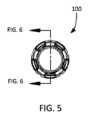
図5から図7を参照すると、チューブコネクタシステム100の端面図及び断面図が示されている。オス型モジュール118は、オス型バルブハウジング128と、当該オス型バルブハウジング128から第1のチューブ金具110に向かって延在するオス型モジュールステム130とを含む。図6及び図8に例示されるように、第1の圧力金具108は、第1のチューブ金具110をねじ込み式で中央コネクタ106に引き入れる間、オス型モジュールステム130の周りを回転するように構成されている。オス型モジュールステム130は、オス型モジュールステム130の中心を通って、オス型バルブハウジング128内部の、オス型モジュールステム130の外端部134からオス型モジュールステム130の内端部136に延在する第1の流体通路132を含んでいる。オス型モジュールステム130は、オス型モジュールステム130の内端部136に近接する1つ以上のオス型モジュール孔138を含んでいる。当該オス型モジュール孔138は、オス型バルブハウジング128内の第1の環状スペース140と流体連結する第1の流体通路132を配置する、オス型モジュールステム130における開口部である。図6及び図8に示されているように、オス型モジュールステム130は、第1の環状スペース140と第1の流体通路132との間で、1つ以上のオス型モジュール孔138を通って、流体交換を強制的に発生させる内端壁142を含んでいる。 5-7, end and cross-sectional views of
メス型モジュール120は、メス型バルブハウジング144と、当該メス型バルブハウジング144から第2のチューブ金具114に延在するメス型モジュールステム146とを含む。図6及び図8に示されているように、第2のチューブ金具114はメス型モジュールステム146内部に適合するように構成され、第2の圧力金具112は、メス型モジュールステム146の外側とのねじ込み式接続のために、メス型モジュールステム146内の第2の流体通路148と流体接続状態にある第2のチューブ金具114とを捕えるよう構成されている。
第2の流体通路148は、メス型モジュールステム146の中心を通って、メス型バルブハウジング144内部のメス型モジュールステム146の外端部150からメス型モジュールステム146の内端部152に延在している。メス型モジュールステム146は、メス型モジュールステム146の内端部152に近接する1つ以上のメス型モジュール孔154を含んでいる。当該1つ以上のメス型モジュール孔154は、メス型バルブハウジング144の第2の環状スペース125と流体連結する第2の流体通路148を配置する、メス型モジュールステム146における開口部である。図6及び図8に示されているように、メス型モジュールステム146は、第2の環状スペース156と第2の流体通路148との間で、1つ以上のメス型モジュール孔154を通って、流体交換を強制的に発生させる内端壁158を含んでいる。 A
第1のバルブ部材124及び第2のバルブ部材126は、第1の環状スペース150及び第2の環状スペース156にそれぞれ維持される。オス型バルブハウジング128は、第1のバルブ部材124を維持するように協働する内部バルブフランジ160、脚部壁(foot wall)162及び外壁(outer wall)164を含んでいる。第1の環状スペース140は、外壁164とオス型モジュールステム130との間に存在する。同様に、メス型バルブハウジング144は、第2のバルブ部材126を維持するように協働する内部バルブフランジ166、脚部壁168及び外壁170を含んでいる。第2の環状スペース156は外壁170とメス型モジュールステム146との間に存在する。
図9Aから図9Cに示されているように、第1のバルブ部材124及び第2のバルブ部材126は、全般に筒状であり、可撓性のあるポリマー又はプラスチックで製造されている。いくつかの実施形態では、第1のバルブ部材124及び第2のバルブ部材126は、USPクラスVI対応のシリコンゴムのようなエラストマー物質から製造されている。第1のバルブ部材124は、第1のバルブ脚部(valve foot)172、第1のバルブベローズ部(valve bellows)174、及び第1のバルブ頭部176(valve head)を含んでいる。第1のバルブ頭部176は、第1のバルブベローズ部174の外径よりも大きな外径を有する。第1のバルブ頭部176は第1のバルブショルダー部178及び、第1のバルブヘッド部176から長手方向に内側に延在する突起180を含んでいる。 As shown in Figures 9A-9C, the
第1のバルブ部材124は、第1のバルブ部材124の内部を通って軸方向に延在する第1のバルブボア182を含んでいる。取り付け時、第1のバルブ部材124は、オス型モジュールステム130の内端部136が第1のバルブボア182内部に配置されるように、オス型モジュール118に配置される。図9Aに記載されているように、第1のバルブ部材124は、第1のバルブショルダー部178に半径方向に内部にある第1のバルブボア182の狭窄によって形成される第1のバルブシール184を含む。第1のバルブシール184は、第1のバルブ部材124が弛緩状態にあるとき(図9A参照)、オス型モジュール孔138を覆う寸法であり、かつそのように構成されている。 The
第2のバルブ部材126は、第2のバルブ脚部186、第2のバルブベローズ部188、及び第2のバルブ頭部190を含んでいる。第2のバルブ頭部190は、第2のバルブベローズ部188の外径よりも大きな外径を有する。第2のバルブ頭部190は第2のバルブショルダー部192及び、第1のバルブ頭部176からの第1のバルブ突起180を精密公差で受け入れるように構成されたレシーバ194を含んでいる。
第2のバルブ部材126は、第2のバルブ部材126の内部を通って軸方向に延在する第2のバルブボア196を含んでいる。取り付け時、第1のバルブ部材124は、メス型モジュールステム146の内端部152が第2のバルブボア196内部に配置されるように、メス型モジュール120に配置される。図9Aに記載されているように、第2のバルブ部材126は、第2のバルブショルダー部192に半径方向に内部にある第2のバルブボア198の狭窄によって形成される第2のバルブシール198を含む。第2のバルブシール198は、第2のバルブ部材126が弛緩状態にあるとき(図9A参照)、メス型モジュール孔154を覆う寸法であり、かつそのように構成されている。
チューブコネクタシステム100のアセンブリ状態において、オス型モジュール118及びメス型モジュール120が接続され(図6参照)、第1のバルブ部材124及び第2のバルブ部材126は、第1のバルブ突起180が第2のバルブ部材126のレシーバ194内で捕らえられるように係合する(図9B参照)。第1のヘッドバルブ176及び第2のヘッドバルブ190がこのような方法で係合しているとき、バルブ間流路200が第1のバルブ部材124と、第2のバルブ部材126との間に、かつそれらの内部に形成される。 In the assembled state of
オス型モジュールステム130及びメス型モジュールステム146が、組立(アセンブリ)状態において近接しているとき、第1のヘッドバルブ176及び第2のヘッドバルブ190は不動のままである。上記は、オス型モジュールステム130の内端部136を、第1のバルブ部材124の第1のバルブシール184を超えて強制的に移動させ、それによりオス型モジュール孔138を露出する。同時に、メス型モジュールステム146の内端部152が第2のバルブ部材126の第2のバルブシール198を超えて押圧され、それによって、メス型モジュール孔154を露出する。この収縮位置において、第1のバルブベローズ部174及び第2のバルブベローズ部188が圧迫され、スプリング力を適用し、第1のバルブ頭部176と第2のバルブ頭部190との間の密閉接続を維持する。このことは、オス型モジュール孔138とメス型モジュール孔154との間を、バルブ間流路200を通って通過する流体が、接続された第1のバルブ部材124及び第2のバルブ部材126内に確実に収容されるようにする(図9B参照)。オス型モジュール118とメス型モジュール120とが離脱するとき、第1のバルブベローズ部174及び第2のバルブベローズ部188が第1のバルブシール184及び第2のバルブシール198を収縮位置(図9B)から展開(deploy)位置(図9A)に押圧し、オス型モジュール孔138とメス型モジュール孔154とを閉鎖する。 When
重要なことに、第1のバルブ部材124及び第2のバルブ部材126は、第1のバルブ頭部176及び第2のバルブ頭部190が、第1のバルブベローズ部174及び第2のバルブベローズ部188のそれぞれと、ジンバル支持により接続されるように構成されている。図9Cに示されているように、第1のバルブ突起180と第2のバルブ頭部190とのレシーバ194の間のプラグ-ソケット接続により、チューブコネクタシステム100が分離するような状態に陥ってオス型モジュールステム130とメス型モジュールステム146との位置がずれたとしても、バルブ間流路200を損ねることなく、第1のバルブ部材124及び第2のバルブ部材126が係合した状態に保つことが可能である。上記により、第1のバルブ部材124及び第2のバルブ部材126が分離状態においてねじれたとしても、潜在的に有害な流体が確実に保持される。 Importantly, the
図10~図18及び図1~図4を参照すると、分離アセンブリ116の様々な描写、特に、オス型モジュール118及びメス型モジュール120の、相互接続する外部要素が示されている(明確にするために、オス型モジュール118及びメス型モジュール120の詳細な内部要素は除かれている)。全般に、オス型モジュール118及びメス型モジュール120は、アセンブリ状態において、オス型モジュール118及びメス型モジュール120が共にロックされるとき、制限された長手方向の直線範囲を提供するために協働する複数のロッキング(ロック式)係合機能を含んでいる。オス型モジュール118及びメス型モジュール120の間の制限された回転、屈曲、又は半径方向の移動に加えて、これらの機構もまた、オス型モジュール118及びメス型モジュール120が分離した後で再接続することを防止する。上記は、オス型モジュール118及びメス型モジュール120が非滅菌の環境において一旦分離すると、チューブコネクタシステム100の再利用を防止するものである。 10-18 and 1-4, various depictions of
オス型モジュール118は、メス型モジュール120に向かって長手方向に内側に突出する複数のスタビライザ202を含んでいる。各スタビライザ202は全般に、オス型モジュール118の筒状形状に合致する、半径方向の湾曲部を伴ったフィンガー(finger)、すなわちタブとして構成されている。例示される実施形態では、スタビライザ202はオス型モジュール118の円周上に均等に分布されている。また、オス型モジュール118は、オス型モジュール118の外側周囲の円周方向に延在するアバットメントリング206から、半径方向に外側に延在する複数のアラインメント(位置合わせ)タブ204を含んでいる。さらに、オス型モジュール118は、アバットメントリング206の内側の、オス型モジュール118周囲に円周方向に延在するロッキングリング208を含んでいる。図4に最もわかりやすく示されているように、スタビライザ202はロッキングリング208に接続可能、及び、そこから延在可能である。
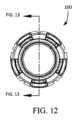
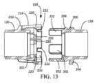
メス型モジュール120は、メス型モジュール120の内端部周囲に円周方向に延在するロッキングカラー210を含んでいる。ロッキングカラー210は、複数のカラーマウント(取り付け具)212によって、メス型モジュール120の外側に取り付けられている。ロッキングカラー210は、オス型モジュール118に向かって内側方向に延在する複数のロッキングタブ214を含んでいる。各ロッキングタブ214は全般にU字型部材として構成されており、カンチレバー形式でクロス部材(横材)216を支持するように、2つの近接した端部が隣接するカラーマウント212に取り付けられている。このように、各ロッキングタブ214は、ロッキングタブ214が取り付けられた隣接するカラーマウント212の間に、スタビライザ凹部218を呈している。
図11及び図13に最もわかりやすく示されているように、ロッキングタブ214は、カンチレバー形式のロッキングカラー210の外側方向の屈曲を制限する、強化された、曲線状内部を伴ったカラーマウント212に取り付けられている。さらに、ロッキングカラー210は円形部材として生成されているため、ロッキングカラーの遠位端、自由端は外側への半径方向の屈曲にさらに抵抗する「フープ強度」を示す。このように、ロッキングカラー210は外側の半径方向の力の適用に対して、スプリング力による抵抗を示す。 As best seen in FIGS. 11 and 13, locking
各ロッキングタブ214のクロス部材216は、クロス部材216から半径方向に内側に突出する複数の歯220を含んでいる。示されているように、各クロス部材216は、クロス部材216の外端部上に、間隔を置いて配置された対の歯220を含んでいる。歯220は、クロス部材216の遠位端から間隔をおいて後退している。また、クロス部材216は、クロス部材216の中央の内側にアラインメントタブ凹部222を含んでいる。各アラインメントタブ凹部222は、オス型モジュール118のアバットメントリング206から半径方向に外側に延在する5つのアラインメントタブ204のうちの対応する1つを収容するように構成されている。ロッキングタブ214及び歯220は、オス型モジュール118の対応するロッキング機構の円形形状に適合するように、筒状に形成される。
例示されているように、メス型モジュール120は、ロッキングカラー210から延在する5つのロッキングタブ214を含んでおり、これにより、オス型モジュール118からの5つのスタビライザ202を収容するための5つのスタビライザ凹部218を形成している。これらのロッキング機構はオス型モジュール118及びメス型モジュール120の円周上に均等に分布されてもよいことを理解されたい。例示される実施形態には、5つのロッキングタブ214、5つのスタビライザ202、及び5つのアラインメントタブ204が示されているが、これらの実施形態の範囲内において、5つよりも多い、又は少ない数の当該機構が検討されてもよいことを理解されたい。例えば、3、4、5、6、7、8、9、10又は11の数のロッキングタブ214、スタビライザ202、及びアラインメントタブ204を含むことが望ましいこともある。いくつかの用途では、偶数よりも奇数の各ロッキング機構が好ましい。 As illustrated,
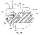
図16から図18の拡大図に最もわかりやすく示されているように、アバットメントリング206は、チューブコネクタシステム100を通って延在する中央長手方向軸に対して実質的に直角である平面において、半径方向に外側に延在するアバットメント面224を含んでいる。ロッキングリング208は傾斜したロッキング面(locking face、係止面)、傾斜した解除面228、及びブロッキング面230を含んでいる。ロッキングリング208のピーク(先端)を通る中央長手方向軸に対して直角に延在する平面を基準にして、ロッキング面226は10°から80°の間の角度で、外側方向に、かつ半径方向に内側に延在している。示されているように、ロッキング面226はメス用モジュール120から離れて長手方向に外側に、かつ、半径方向に内側に約45°の角度で延在している。同一の直角平面を基準にして、解除面228は半径方向に内側に、かつメス型モジュール120に向かって長手方向に、約45°の角度で傾斜している。他の実施形態では、解除面228は10°から80°の間の角度で構成されることができる。ロッキング面226は円形のピーク232で解除面228と交わる。ブロッキング面230は中央長手方向軸に対して実質的に直角な平面において、半径方向に外側に延在している。いくつかの実施形態では、ロッキングリング208の長手方向長さは、各アラインメントタブ204の長手方向長さとほぼ同一である。 As best seen in the enlarged views of FIGS. 16-18, the
各歯220は、ロッキング面226の角度と実質的に一致する角度でスロープ面234を含んでいる(図16参照)。各歯220は、スロープ面234を防止面238に結合する円形の歯頂部236を有している。このように、スロープ面234及び防止面は、10°から80°の間の角度で向いており、図16では約45°の角度である。 Each
オス型モジュール118及びメス型モジュール120が接続されると、各スタビライザ202は対応するスタビライザ凹部218の1つに捕らえられる。各アラインメントタブ204は対応するアラインメントタブ凹部222の1つに捕らえられる。各歯220は、スロープ面234が、ロッキングリング208の傾斜したロッキング面と接触して係合するロック位置で係合する(図1、図2、図6、図11、図16及び図18参照)。オス型モジュール118及びメス型モジュール120のさらなる接近は、防止面238とアバットメント面224との間の接触により防止される。この位置において、捕えられたスタビライザ202及び捕えられたアラインメントタブ204は、オス型モジュール118及びメス型モジュール120の回転、屈曲、又はさらなる接近を防止する。唯一許される動作、すなわち、オス型モジュール118及びメス型モジュール120の直線的な分離は、ロッキングリング208に対する歯220の係合によって制限される。 Each
中央長手方向軸に沿って反対方向に引っ張ることによる、オス型モジュール118及びメス型モジュール120を分離させようとする試みは、歯220がロッキングリング208のロッキング面226を引っ張り上げるため、ロッキングカラー210を半径方向に外側に湾曲させる原因となる。ロッキングカラー210の剛性は、オス型モジュール118及びメス型モジュール120の間の張力が、歯頂部236をロッキング面と解除(リリース)面228との間のロッキングリング208のピーク232に到達させるまで、この変形に抵抗する。ピーク232及び歯頂部236は、オス型モジュール118及びメス型モジュール120の相対運動が、ピーク232が歯頂部236に接触しているときに停滞しないように設計されている。歯頂部234が引っ張られてピーク232と接触すると、ロッキングカラー210によって解除面228の内側方向の傾斜上の歯220に課された内側方向の圧力が、オス型モジュール118及びメス型モジュール120を、素早く互いに離れるように弾かせる。上記により、オス型モジュール118及びメス型モジュール120が、バルブアセンブリ122によって提供される密閉を損なう可能性のある「分離力閾値(threshold separation force)」に反応した「長手方向分離距離閾値(threshold longitudinal separation distance)」によって引き離されると、オス型モジュール118及びメス型モジュール120は素早く分離し、第1のバルブ部材124と第2のバルブ部材126とは展開状態に戻り、オス型モジュール孔138及びメス型モジュール孔154を介した漏出や汚染を防止する。したがって、例示的な実施形態では、オス型モジュール118及びメス型モジュール120が分離する前に、バルブアセンブリ122を確実に閉位置に展開するために、第1のバルブシール184及び第2のバルブシール189に関する長手方向の移動距離(「バルブ移動距離」)は長手方向分離距離閾値よりも小さい。 Attempting to separate
重要なことに、長手方向分離距離閾値は、アラインメントタブ204及びアラインメントタブ222の長手方向長さと同一の距離であることが好ましい。上記は、オス型モジュール118及びメス型モジュール120がロック解除され、遊離されるまで、互いに対して回転することを防止する。オス型モジュール118及びメス型モジュール120を分離するのに必要な分離力閾値は、ロッキングリング208及び歯220のはめ合い部品の形状を変更することによって調節可能である。ロッキング面226及びスロープ(傾斜した)面234の傾斜が増加すると、オス型モジュール118及びメス型モジュール120を分離するのに必要な張力の大きさが増加する。同様に、長手方向分離距離閾値は、ロッキング面226及びスロープ面234の一方又は両方の長手方向距離を増加又は減少することによって調節可能である。 Importantly, the longitudinal separation threshold is preferably the same distance as the longitudinal length of
オス型モジュール118及びメス型モジュール120が分離すると(図3、図4、図8、図13、図15及び図17参照)、ロッキングリング208及び歯220の形状が、中央コネクタ106の再接続を防止する。図17に最もわかりやすく例示されているように、防止面238及びブロッキング面230は、オス型モジュール118及びメス型モジュール120を共に押圧して、単純に、歯220の防止面238をブロッキング面230に当接させるように、方向付けられている。ブロッキング面230は、歯220が上方向に押圧され、ロッキングリング208より押し上げられることを防止する。特に、歯220は、中央コネクタ106がロックされるとき(図16参照)、アバットメントリング206を覆う、又は、中央コネクタ106が分離したとき(図17参照)、ロッキングリング208のロッキング面226を覆うのに十分な距離によって、ロッキングタブ214の遠位端に近接して配置される。これにより、患者又は介護者が、中央コネクタ106のオス型モジュール118及びメス型モジュール120を分離又は再接続するために、ロッキングカラー210及び歯220を持ち上げようとして、工具を用いてロッキングカラー210の下方をこじ開けることを防止することができる。 When
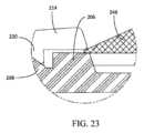
図19から図23に示されているように、アセンブリ状態において、オス型モジュール118は、アセンブリツール240を使用してメス型モジュール120と係合する。アセンブリツール240は、一連のウェッジ(楔)246及びリリーフ248を含む円錐状ノーズ244を伴う筒状本体242を有する。リリーフ248は、オス型モジュール118がアセンブリツール240を通過するときにアラインメントタブ204を収容するサイズと配置となっている。アセンブリツール240は、ウェッジ246がメス型モジュール120のロッキングタブ214の遠位端と、オス型モジュール118のアバットメントリング206との間に配置されるように、オス型モジュール118上に挿入される。アセンブリツール240は、メス型モジュール120に向かって押し込まれ、ロッキングリング208のピーク232が、内側に方向付けられた各歯220の頂部236内を通過できるのに必要な大きさでロッキングカラー210を外側方向に広げる。オス型モジュール118をメス型モジュール120に押し込むのに別のツールが使われてもよい。ロッキングリング208が外側に広がった歯220内を通過すると、アセンブリツール240はオス型モジュール118の位置を維持しながら引き抜かれることができ、それによって、バネ荷重のロッキングカラー210が、歯220をロッキングリング208とロックされた係合状態にすることを可能にする。図23は、ロッキングカラー210の歯220をロッキングリング208に向かって低く下げ、アセンブリツール240を引き抜くところを描写している。 In the assembled state,
本発明は、その目的を遂行し、上述の目的及び利点ならびにそこに固有のものを達成するためによく適合していることは明らかである。本発明の現在好ましい実施形態は、開示の目的のために様々な詳細で説明されてきたが、当業者に容易に示唆され、本明細書に開示された本発明の主旨の範囲内に包含される多数の変更がなされ得ることが理解されよう。 It is evident that the present invention is well adapted to carry out the objects and attain the ends and advantages mentioned as well as those inherent therein. Although the presently preferred embodiments of the invention have been described in various details for purposes of disclosure, they are readily suggested to those skilled in the art and are encompassed within the spirit of the invention disclosed herein. It will be appreciated that numerous modifications may be made.
Claims (21)
Translated fromJapanese第1のチューブアダプタと、
第2のチューブアダプタと、
前記第1のチューブアダプタと前記第2のチューブアダプタとの間の中央コネクタと、を備え、
前記中央コネクタは、
オス型モジュールと、
メス型モジュールと、
バルブアセンブリと、を備え、前記バルブアセンブリは、
前記オス型モジュール内に維持された第1のバルブ部材と、
前記メス型モジュール内に維持された第2のバルブ部材と、を備え、
前記オス型モジュール及び前記メス型モジュールは、前記オス型モジュールと前記メス型モジュールとが一度分離されると、再接続を防止するように構成されている、チューブコネクタシステム。A tube connector system for use in connecting two pieces of medical tubing, comprising:
a first tube adapter;
a second tube adapter;
a central connector between the first tube adapter and the second tube adapter;
The central connector is
a male module;
a female module;
a valve assembly, the valve assembly comprising:
a first valve member retained within the male module;
a second valve member retained within the female module;
A tube connector system, wherein the male module and the female module are configured to prevent reconnection once the male module and the female module are separated.
ロッキングリングと、
アバットメントリングと、
前記アバットメントリングから半径方向に外側に延在する複数のアラインメントタブと、
複数のスタビライザと、を備える、請求項1に記載のチューブコネクタシステム。said male module comprising a locking ring;
abutment ring and
a plurality of alignment tabs extending radially outward from the abutment ring;
2. The tube connector system of claim 1, comprising a plurality of stabilizers.
前記ロッキングリングと係合する複数のロッキングタブと、
複数のアラインメントタブ凹部であって、前記複数のアラインメントタブ凹部のそれぞれは、前記複数のアラインメントタブのうち、対応する1つを受けるように構成される複数のアラインメントタブ凹部と、
前記ロッキングリングと係合する複数のロッキングタブと、
複数のスタビライザ凹部であって、前記複数のスタビライザ凹部のそれぞれは、前記複数のスタビライザのうち、対応する1つを受けるように構成されている、複数のスタビライザ凹部と、を備える、請求項3に記載のチューブコネクタシステム。The locking collar is
a plurality of locking tabs engaging the locking ring;
a plurality of alignment tab recesses, each of said plurality of alignment tab recesses configured to receive a corresponding one of said plurality of alignment tabs;
a plurality of locking tabs engaging the locking ring;
4. A plurality of stabilizer recesses, each of said plurality of stabilizer recesses comprising a plurality of stabilizer recesses configured to receive a corresponding one of said plurality of stabilizers. The described tube connector system.
第1のバルブ脚部と、
第1のバルブ頭部と、
前記第1のバルブ脚部と前記第1のバルブ頭部の間の第1のバルブ部と、を備える、請求項1に記載のチューブコネクタシステム。The first valve member is
a first valve leg;
a first valve head;
2. The tube connector system of claim 1, comprising a first valve portion between the first valve leg and the first valve head.
第2のバルブ脚部と、
第2のバルブ頭部と、
前記第2のバルブ脚部と前記第2のバルブ頭部の間の第2のバルブベローズ部と、を備える、請求項6に記載のチューブコネクタシステム。The second valve member comprises:
a second valve leg;
a second valve head;
7. The tube connector system of claim 6, comprising a second valve bellows portion between the second valve leg and the second valve head.
オス型モジュールと、
メス型モジュールであって、前記メス型モジュールは、複数のロッキング機構を備えた前記オス型モジュールと接続状態で維持される、メス型モジュールと、を備え、
前記複数のロッキング機構は、前記オス型モジュールが前記メス型モジュールから分離された後に、前記オス型モジュールと前記メス型モジュールとが再接続することを防止するように構成されている、チューブコネクタシステム。A tube connector system configured to connect first and second pieces of medical tubing, comprising:
a male module;
a female module, said female module maintained in connection with said male module comprising a plurality of locking mechanisms;
The tube connector system, wherein the plurality of locking mechanisms are configured to prevent reconnection of the male module and the female module after the male module is separated from the female module. .
前記ロッキングカラーは、
複数のカラーマウントと、
複数のロッキングタブであって、前記複数のロッキングタブのそれぞれが、カンチレバー形式の構成で、隣接するカラーマウントの対応する対によって支持され、前記複数のロッキングタブのそれぞれは、
クロス部材と、
スタビライザ凹部と、を備える、複数のロッキングタブと、
前記クロス部材から半径方向に内側に延在する複数の歯と、を備える、請求項12に記載のチューブコネクタシステム。said female module having a locking collar;
The locking collar is
multiple color mounts and
a plurality of locking tabs, each of said plurality of locking tabs supported by a corresponding pair of adjacent collar mounts in a cantilever-type configuration, each of said plurality of locking tabs:
a cross member;
a plurality of locking tabs comprising stabilizer recesses;
and a plurality of teeth extending radially inwardly from the cross member.
前記ロッキングカラーの前記複数の歯と係合するように構成されたロッキングリングと、
前記ロッキングリングから延在する複数のスタビライザであって、前記複数のスタビライザのそれぞれが、前記ロッキングタブの対応する1つの前記スタビライザ凹部に向かって長手方向に延在するように構成された、複数のスタビライザと、を備える、請求項14に記載のチューブコネクタシステム。The male module comprises:
a locking ring configured to engage the plurality of teeth of the locking collar;
a plurality of stabilizers extending from the locking ring, each of the plurality of stabilizers configured to longitudinally extend toward a corresponding one of the stabilizer recesses of the locking tabs; 15. The tube connector system of claim 14, comprising a stabilizer.
ロッキング面と、
解除面と、
前記ロッキング面と前記解除面との間のピークと、
ブロッキング面と、を備える、請求項15に記載のチューブコネクタシステム。The locking ring is
a locking surface;
a release surface;
a peak between the locking surface and the unlocking surface;
16. The tube connector system of claim 15, comprising a blocking surface.
スロープ面と、
防止面と、
前記スロープ面と前記防止面との間の歯頂部と、を備える、請求項16に記載のチューブコネクタシステム。each of the plurality of teeth,
a slope surface;
a preventive aspect;
and a crest between the slope surface and the blocking surface.
オス型モジュールと、
メス型モジュールと、
前記オス型モジュールを前記メス型モジュールに解除可能にロックする手段と、を備え、
前記オス型モジュールを前記メス型モジュールに解除可能にロックする前記手段は、前記オス型モジュールが前記メス型モジュールに再び取り付けされることをまた防止する、チューブコネクタシステム。A tube connector system configured to connect a first piece of medical tubing to a second piece of medical tubing, comprising:
a male module;
a female module;
means for releasably locking the male module to the female module;
The tube connector system of claim 1, wherein said means for releasably locking said male module to said female module also prevents said male module from being reattached to said female module.
Applications Claiming Priority (3)
| Application Number | Priority Date | Filing Date | Title |
|---|---|---|---|
| US202063032609P | 2020-05-30 | 2020-05-30 | |
| US63/032,609 | 2020-05-30 | ||
| PCT/US2021/035074WO2021247458A1 (en) | 2020-05-30 | 2021-05-31 | Tubing system with reassembly prevention mechanism |
Publications (1)
| Publication Number | Publication Date |
|---|---|
| JP2023528388Atrue JP2023528388A (en) | 2023-07-04 |
Family
ID=78704765
Family Applications (1)
| Application Number | Title | Priority Date | Filing Date |
|---|---|---|---|
| JP2022573492APendingJP2023528388A (en) | 2020-05-30 | 2021-05-31 | Tubing system including anti-reassembly mechanism |
Country Status (7)
| Country | Link |
|---|---|
| US (1) | US20210372551A1 (en) |
| EP (1) | EP4157428A4 (en) |
| JP (1) | JP2023528388A (en) |
| CN (1) | CN115968311A (en) |
| AU (1) | AU2021283094A1 (en) |
| CA (1) | CA3180914A1 (en) |
| WO (1) | WO2021247458A1 (en) |
Families Citing this family (4)
| Publication number | Priority date | Publication date | Assignee | Title |
|---|---|---|---|---|
| BR102021004374A2 (en)* | 2021-03-08 | 2022-09-13 | Sumitomo Riko Company Limited | QUICK COUPLING FOR AUTOMOTIVE FLUID CONDUCTION PIPES |
| US12109387B2 (en)* | 2022-11-11 | 2024-10-08 | Carefusion 303, Inc. | Connector coupling assembly |
| US20240167602A1 (en)* | 2022-11-18 | 2024-05-23 | Carefusion 303, Inc. | Connector coupling assembly |
| US20240377007A1 (en)* | 2023-05-09 | 2024-11-14 | Carefusion 303, Inc. | Locking connector coupling assembly |
Citations (2)
| Publication number | Priority date | Publication date | Assignee | Title |
|---|---|---|---|---|
| JP2018522648A (en)* | 2015-06-24 | 2018-08-16 | リニアー ヘルス サイエンス,エルエルシー | Tube system |
| US20190224468A1 (en)* | 2015-08-13 | 2019-07-25 | Site Saver, Inc. | Breakaway medical tubing connector |
Family Cites Families (10)
| Publication number | Priority date | Publication date | Assignee | Title |
|---|---|---|---|---|
| WO1994023775A1 (en)* | 1993-03-23 | 1994-10-27 | Abbott Laboratories | Securing collar for cannula connector |
| US7004934B2 (en)* | 2001-09-06 | 2006-02-28 | Vaillancourt Vincent L | Closed system connector assembly |
| ITMI20020819A1 (en)* | 2002-04-18 | 2003-10-20 | Gambro Lundia Ab | CONNECTION ELEMENT AND CONNECTION DEVICE FOR MEDICAL USE PIPES |
| FR2847329B1 (en)* | 2002-11-19 | 2007-01-05 | Staubli Sa Ets | QUICK COUPLING FOR THE REMOVABLE JOINING OF TWO PIPES |
| US7875019B2 (en)* | 2005-06-20 | 2011-01-25 | C. R. Bard, Inc. | Connection system for multi-lumen catheter |
| BRPI0717401A2 (en)* | 2006-10-25 | 2013-11-12 | Icu Medical Inc | CONNECTOR FOR MEDICAL USE |
| US8647326B2 (en)* | 2007-01-16 | 2014-02-11 | Catheter Connections, Inc. | System for cleaning luer connectors |
| JP5041920B2 (en)* | 2007-08-24 | 2012-10-03 | 日本コヴィディエン株式会社 | Lock connector |
| ES2935418T3 (en)* | 2011-08-10 | 2023-03-06 | Fisher & Paykel Healthcare Ltd | Conduit connector for a patient breathing device |
| KR101361088B1 (en)* | 2013-07-11 | 2014-02-12 | 조희민 | A syringe with a prevention type pening and closing cap |
- 2021
- 2021-05-31CACA3180914Apatent/CA3180914A1/enactivePending
- 2021-05-31JPJP2022573492Apatent/JP2023528388A/enactivePending
- 2021-05-31AUAU2021283094Apatent/AU2021283094A1/enactivePending
- 2021-05-31CNCN202180039184.0Apatent/CN115968311A/enactivePending
- 2021-05-31EPEP21818832.4Apatent/EP4157428A4/enactivePending
- 2021-05-31WOPCT/US2021/035074patent/WO2021247458A1/ennot_activeCeased
- 2021-05-31USUS17/335,060patent/US20210372551A1/enactivePending
Patent Citations (2)
| Publication number | Priority date | Publication date | Assignee | Title |
|---|---|---|---|---|
| JP2018522648A (en)* | 2015-06-24 | 2018-08-16 | リニアー ヘルス サイエンス,エルエルシー | Tube system |
| US20190224468A1 (en)* | 2015-08-13 | 2019-07-25 | Site Saver, Inc. | Breakaway medical tubing connector |
Also Published As
| Publication number | Publication date |
|---|---|
| AU2021283094A1 (en) | 2022-12-15 |
| US20210372551A1 (en) | 2021-12-02 |
| WO2021247458A1 (en) | 2021-12-09 |
| EP4157428A1 (en) | 2023-04-05 |
| CN115968311A (en) | 2023-04-14 |
| CA3180914A1 (en) | 2021-12-09 |
| EP4157428A4 (en) | 2024-07-03 |
Similar Documents
| Publication | Publication Date | Title |
|---|---|---|
| JP2023528388A (en) | Tubing system including anti-reassembly mechanism | |
| US10857346B2 (en) | Tubing system | |
| US20240148610A1 (en) | System for Closed Transfer of Fluids | |
| JP6122005B2 (en) | Medical system with retractable luer lock fitting | |
| BR112016024680B1 (en) | SYRINGE ADAPTER | |
| EP3071255B1 (en) | Medical luer connector | |
| JP2025511216A (en) | Medical Connectors | |
| US12161604B2 (en) | Quick release connection for patient tube assembly | |
| US20240316330A1 (en) | Fluid connector system | |
| US20240358989A1 (en) | Fluid connector system | |
| US20250249228A1 (en) | Fluid connector assembly | |
| US20240042188A1 (en) | Coupling device for medical tubing | |
| CN222488365U (en) | Twist-on connector assembly | |
| WO2025165676A1 (en) | Hazardous drug safety device | |
| NZ741983B2 (en) | Medical luer connector |
Legal Events
| Date | Code | Title | Description |
|---|---|---|---|
| A621 | Written request for application examination | Free format text:JAPANESE INTERMEDIATE CODE: A621 Effective date:20240530 | |
| A977 | Report on retrieval | Free format text:JAPANESE INTERMEDIATE CODE: A971007 Effective date:20250219 | |
| A131 | Notification of reasons for refusal | Free format text:JAPANESE INTERMEDIATE CODE: A131 Effective date:20250311 | |
| A521 | Request for written amendment filed | Free format text:JAPANESE INTERMEDIATE CODE: A523 Effective date:20250611 | |
| A131 | Notification of reasons for refusal | Free format text:JAPANESE INTERMEDIATE CODE: A131 Effective date:20250617 | |
| A521 | Request for written amendment filed | Free format text:JAPANESE INTERMEDIATE CODE: A523 Effective date:20250916 |