JP2023524897A - Multiload Adaptive Gravity Compensation Method, Apparatus and Control Device for Robotic Arm - Google Patents
Multiload Adaptive Gravity Compensation Method, Apparatus and Control Device for Robotic ArmDownload PDFInfo
- Publication number
- JP2023524897A JP2023524897AJP2022569139AJP2022569139AJP2023524897AJP 2023524897 AJP2023524897 AJP 2023524897AJP 2022569139 AJP2022569139 AJP 2022569139AJP 2022569139 AJP2022569139 AJP 2022569139AJP 2023524897 AJP2023524897 AJP 2023524897A
- Authority
- JP
- Japan
- Prior art keywords
- tool
- robot arm
- mass
- load
- gravity
- Prior art date
- Legal status (The legal status is an assumption and is not a legal conclusion. Google has not performed a legal analysis and makes no representation as to the accuracy of the status listed.)
- Granted
Links
Images


Classifications
- B—PERFORMING OPERATIONS; TRANSPORTING
- B25—HAND TOOLS; PORTABLE POWER-DRIVEN TOOLS; MANIPULATORS
- B25J—MANIPULATORS; CHAMBERS PROVIDED WITH MANIPULATION DEVICES
- B25J9/00—Programme-controlled manipulators
- B25J9/16—Programme controls
- B25J9/1628—Programme controls characterised by the control loop
- B25J9/1633—Programme controls characterised by the control loop compliant, force, torque control, e.g. combined with position control
- B—PERFORMING OPERATIONS; TRANSPORTING
- B25—HAND TOOLS; PORTABLE POWER-DRIVEN TOOLS; MANIPULATORS
- B25J—MANIPULATORS; CHAMBERS PROVIDED WITH MANIPULATION DEVICES
- B25J9/00—Programme-controlled manipulators
- B25J9/16—Programme controls
- B25J9/1602—Programme controls characterised by the control system, structure, architecture
- B25J9/1605—Simulation of manipulator lay-out, design, modelling of manipulator
- B—PERFORMING OPERATIONS; TRANSPORTING
- B25—HAND TOOLS; PORTABLE POWER-DRIVEN TOOLS; MANIPULATORS
- B25J—MANIPULATORS; CHAMBERS PROVIDED WITH MANIPULATION DEVICES
- B25J9/00—Programme-controlled manipulators
- B25J9/16—Programme controls
- B25J9/1628—Programme controls characterised by the control loop
- B25J9/1653—Programme controls characterised by the control loop parameters identification, estimation, stiffness, accuracy, error analysis
Landscapes
- Engineering & Computer Science (AREA)
- Robotics (AREA)
- Mechanical Engineering (AREA)
- Automation & Control Theory (AREA)
- Manipulator (AREA)
Abstract
Translated fromJapaneseDescription
Translated fromJapanese本願は、ロボット技術分野に関し、特に、ロボットアームの多負荷適応重力補償法、装置及び制御デバイスに関する。 TECHNICAL FIELD The present application relates to the field of robotic technology, and more particularly to multi-load adaptive gravity compensation methods, apparatus and control devices for robotic arms.
<関連出願の相互引用>
本願は、2020年5月28日に中国特許庁に提出された、出願番号が202010466099.Xであり、名称が「ロボットアームの多負荷適応重力補償法」である中国特許出願の優先権を主張し、その全ての内容が引用により本願に組み込まれている。<Cross-citation of related applications>
This application is filed with the Chinese Patent Office on May 28, 2020, with application number 202010466099. X and entitled “Multi-Load Adaptive Gravity Compensation Method for Robotic Arm”, the Chinese patent application, the entire content of which is incorporated herein by reference.
ロボットアーム製造業及びセンサー産業の更なる発展に伴い、ロボットアームは、既に生産ラインに役立つだけでなく、生活の様々な分野にも徐々に参入し始めている。従来の産業用ロボットアームは、人身事故を防ぐために、セキュリティ範囲を設定し、操作中に人員が作業エリアに立ち入ることを厳しく禁止する必要がある。しかしながら、多くの生活の応用シナリオでは、セキュリティ範囲を設定する際に多くの不都合が生じ、人間と機械の協調作業の際においても効率が高くない。人間と機械の作業空間を分断しないことにより、本当の高効率で且つ高精度の人間と機械の協調作業を実現するために、人々は、協調型ロボットアームを設計した。協調型ロボットアームは、接触力を感知する能力を有し、人体とロボットアームの物理的な接触に反応することができるため、オペレーターとロボットアームは、作業空間を共有することができる。協調型ロボットアームの登場により、ホームケア、教育娯楽、健康医療、高度な製造業等の産業におけるロボットアームの応用が大幅に拡大され、ロボットアームの高効率、高精度、高安定性の特徴を利用して生活のあらゆる側面を改善することができた。 With the further development of the robot arm manufacturing industry and the sensor industry, the robot arm has not only served the production line, but also gradually entered various fields of life. Conventional industrial robot arms need to set security perimeters and strictly prohibit personnel from entering the work area during operation in order to prevent personal injury. However, in many life application scenarios, there are many inconveniences in setting the security scope, and the efficiency of human-machine cooperation is not high. In order to realize true high-efficiency and high-precision human-machine collaborative work by not dividing the human-machine working space, people designed collaborative robot arms. A collaborative robotic arm has the ability to sense contact forces and can respond to physical contact between the human body and the robotic arm, allowing the operator and the robotic arm to share a workspace. With the advent of cooperative robot arms, the application of robot arms in home care, education and entertainment, health care, advanced manufacturing and other industries has been greatly expanded, highlighting the characteristics of high efficiency, high precision and high stability of robot arms. I was able to use it to improve every aspect of my life.
ゼロフォース制御技術とは、ドラッグティーチングの過程では、ロボットアーム自身の重力の影響を受けていないかのように、ロボットアームがスムーズに外力に応じて移動できることを意味する。この技術は、ドラッグティーチングの労働強度を軽減し、人間によりロボットアームを制御する際の流暢さを向上させることができる。ロボットアームがエンドツールをクランプした状態でも、依然としてゼロフォース制御を実現することができるために、ロボットアーム本体とツールに対してそれぞれパラメータのキャリブレーションをし、リバースエンジニアリング手法を用いてロボットアームの各セグメントのアーム及びツールの質量及び質量中心を正確に計算する必要がある。ロボットアーム本体のパラメータのキャリブレーションの技術は、文献Identifying the dynamic model used by the KUKA LWR: A reverse engineering approach.(C.Gaz,F.Flacco)及びGravity compensation of KUKA LBR IIWA Through Fast Robot Interface.(C.Hou,Y.Zhao)に詳しく紹介されているが、エンドツールのパラメータのキャリブレーションに関する資料が比較的少ない。一部の複雑な応用では、ロボットアームは、作業を完了するために、エンドツールを交換する必要がある。この場合、ロボットアームは、異なるエンドツールの全てがゼロフォース制御を得られるために、如何にツールの重力を適応的に補償できるかが、協調作業がスムーズであるかどうかの鍵になる。 Zero-force control technology means that the robot arm can move smoothly in response to external forces during the drag teaching process, as if it were not affected by the gravity of the robot arm itself. This technology can reduce the labor intensity of drug teaching and improve the fluency in controlling the robot arm by humans. In order to still achieve zero force control even when the robot arm clamps the end tool, we calibrate the parameters for the robot arm body and the tool, and use the reverse engineering method to calibrate the parameters of the robot arm. The segment arm and tool masses and centers of mass must be accurately calculated. A technique for calibrating the parameters of the robot arm body is described in the document Identifying the dynamic model used by the KUKA LWR: A reverse engineering approach. (C. Gaz, F. Flacco) and Gravity compensation of KUKA LBR IIWA Through Fast Robot Interface. (C. Hou, Y. Zhao), there is relatively little documentation on the calibration of end tool parameters. In some complex applications, the robotic arm needs to change end tools to complete the task. In this case, since the robot arm can obtain zero force control for all different end tools, the key to smooth cooperative work is how to adaptively compensate for the gravity of the tools.
現在、ロボットアームの重力補償の方案は、一般的には、まず、計量器を用いてエンドツールの質量を測定し、吊り下げ法又は支持法を用いてツールの質量中心を測定する必要がある。次に、測定して得られたデータをロボットアームの制御システムに導入し、制御システムにツールのパラメータに基づいて重力の補償を行わせ、ロボットアームにゼロフォース制御を実現させる。ただし、ツールの質量と質量中心を測定する際には、ツールがシステムと分離されている状態であり、測定して得られたパラメータは、取り付けプロセスが質量と質量中心に対する影響を省略する傾向がある。また、一度に1つのツールのパラメータのみに対して重力の補償を行うことができ、ツールを切り替える時にプログラムを停止する必要があり、複数のツールを頻繁に切り替える必要がある場合、効率が低下してしまう。 At present, the gravitational compensation scheme of the robot arm generally needs to first use the weighing scale to measure the mass of the end tool, and then use the suspension method or the support method to measure the center of mass of the tool. . Then, the data obtained by the measurement is introduced into the control system of the robot arm, and the control system is made to perform gravity compensation based on the parameters of the tool, so that the robot arm achieves zero force control. However, when measuring the mass and center of mass of the tool, the tool is isolated from the system and the measured parameters tend to omit the effects of the installation process on mass and center of mass. be. Also, gravity compensation can only be done for one tool parameter at a time, requiring the program to be stopped when switching tools, which is less efficient if multiple tools need to be switched frequently. end up
本願の目的の1つとしては、ロボットアームの多負荷適応重力補償法、装置、制御デバイス及び読み取り可能な記憶媒体を提供することで、操作ステップを減らし、効率及び重力補償の性能を高めることが含まれている。 One of the objectives of the present application is to provide a multi-load adaptive gravity compensation method, apparatus, control device and readable storage medium for robotic arms to reduce operation steps and increase efficiency and performance of gravity compensation. include.
上述した目的を実現するために、本願による技術案は、以下の通りである。 In order to achieve the above objectives, the technical solution of the present application is as follows.
第一の局面においては、本願の実施例は、以下のステップを備えるロボットアームの多負荷適応重力補償法を提供する。 In a first aspect, embodiments of the present application provide a multi-load adaptive gravity compensation method for a robot arm comprising the following steps.
ステップS1.1においては、ロボットアームの運動学モデルを構築する。 In step S1.1, a kinematic model of the robot arm is constructed.
ステップS1.2においては、動力学モデルの重力項を再構築する。 In step S1.2, the gravitational term of the dynamics model is reconstructed.
ステップS1.3においては、無負荷静的位置サンプリングをする。 In step S1.3, no-load static position sampling is performed.
ステップS1.4においては、各ツールを取り付けた後にそれぞれ静的位置サンプリングをする。 In step S1.4, static position sampling is performed after each tool is installed.
ステップS1.5においては、各ツールのキャリブレーション待ちのパラメータ値をそれぞれ計算する。 In step S1.5, the parameter values awaiting calibration for each tool are calculated respectively.
ステップS1.6においては、各ツールの質量及び質量中心をそれぞれ計算する。 In step S1.6, the mass and center of mass of each tool are calculated respectively.
ステップS2.1においては、現在、取り付けられているツールによりフランジに加えられる力を計算する。 In step S2.1, the force exerted on the flange by the currently installed tool is calculated.
ステップS2.2においては、ツールの重力を補償する。 In step S2.2, the gravity of the tool is compensated.
1つの可能な実現方法では、ステップS1.1において、標準D-H法を用いてロボットアームの関節座標系を構築する。 In one possible implementation, in step S1.1, the standard DH method is used to construct the joint coordinate system of the robot arm.
1つの可能な実現方法では、ステップS1.3において、ロボットアームが無負荷の状況で、作業空間内の任意の非特異位置に移動し、関節の位置及びモーメントの読み取り値をサンプリングする。 In one possible implementation, in step S1.3, the robot arm is moved in an unloaded situation to any non-singular position in the workspace and samples joint position and moment readings.
1つの可能な実現方法では、ステップS1.4において、各ツールが何回かに分けてロボットアームの末端に取り付けられ、ステップS1.3を繰り返して静的位置サンプリングを行う。 In one possible implementation, in step S1.4 each tool is attached in batches to the end of the robot arm and step S1.3 is repeated to perform static position sampling.
1つの可能な実現方法では、ステップS1.4において、各ツールについて、当該ツールをロボットアームの末端に取り付けた後、当該ツールのサイズに基づいて当該ツールに対応するロボットアームの現在の有効な作業空間を決定し、有効な作業空間に基づいてステップS1.3を繰り返して当該ツールに対して静的位置サンプリングを行う。 In one possible implementation, in step S1.4, for each tool, after attaching the tool to the end of the robot arm, the current available work of the robot arm corresponding to the tool is calculated based on the size of the tool. Determine the space and repeat step S1.3 based on the available working space to perform static position sampling for the tool.
1つの可能な実現方法では、ステップS1.5において、ステップS1.3及びステップS1.4で得られたサンプリングデータを、ツールに基づいてグループ化し、順にステップS1.2の重力項に代入する。 In one possible implementation, in step S1.5, the sampling data obtained in steps S1.3 and S1.4 are grouped based on the tool and substituted in turn into the gravity term of step S1.2.
1つの可能な実現方法では、ステップS1.6において、各ツールについて、当該ツール携帯時にキャリブレーションされたパラメータ値と無負荷でキャリブレーションされたパラメータ値を比較し、比較結果および当該ツールの質量、当該ツールの質量中心、ロボットアームのエンドセグメントアームの質量及びエンドセグメントアームの質量中心の関連関係に基づき、当該ツールの質量及び質量中心を計算する。 In one possible implementation, in step S1.6, for each tool, the parameter values calibrated when the tool is carried and the parameter values calibrated without load are compared, the comparison result and the mass of the tool, Based on the relationship between the center of mass of the tool, the mass of the end segment arm of the robot arm, and the center of mass of the end segment arm, the mass and center of mass of the tool are calculated.
第二の局面においては、本願の実施例は、モデル構築モジュール、重力再構築モジュール、位置サンプリングモジュール、位置サンプリングモジュール、パラメータキャリブレーションモジュール、質量パラメータ計算モジュール、外力計算モジュール及び重力補償モジュールを備えるロボットアームの多負荷適応重力補償装置を提供する。 In a second aspect, embodiments of the present application provide a robot comprising a model building module, a gravity reconstruction module, a position sampling module, a position sampling module, a parameter calibration module, a mass parameter calculation module, an external force calculation module, and a gravity compensation module. A multi-load adaptive gravity compensator for the arm is provided.
モデル構築モジュールは、ロボットアームの運動学モデルを構築するように配置されている。 A model building module is arranged to build a kinematic model of the robot arm.
重力再構築モジュールは、動力学モデルの重力項を再構築するように配置されている。 A gravity reconstruction module is arranged to reconstruct the gravity term of the dynamics model.
位置サンプリングモジュールは、無負荷静的位置サンプリングをするように配置されている。 The position sampling module is arranged for no-load static position sampling.
位置サンプリングモジュールは、さらに、各ツールを取り付けた後にそれぞれ静的位置サンプリングをするように配置されている。 The position sampling module is further arranged to perform each static position sampling after mounting each tool.
パラメータキャリブレーションモジュールは、各ツールのキャリブレーション待ちのパラメータ値をそれぞれ計算するように配置されている。 A parameter calibration module is arranged to calculate respective parameter values awaiting calibration for each tool.
質量パラメータ計算モジュールは、各ツールの質量及び質量中心をそれぞれ計算するように配置されている。 A mass parameter calculation module is arranged to calculate the mass and center of mass of each tool respectively.
外力計算モジュールは、現在、取り付けられているツールによりフランジに加えられる力を計算するように配置されている。 An external force calculation module is now arranged to calculate the force exerted on the flange by the attached tool.
重力補償モジュールは、ツールの重力を補償するように配置されている。 A gravity compensation module is arranged to compensate for the gravity of the tool.
1つの可能な実現方法では、前記モデル構築モジュールは、ロボットアームの運動学モデルを構築する過程において、標準D-H法を用いてロボットアームの関節座標系を構築する。 In one possible implementation, the model building module builds the joint coordinate system of the robot arm using the standard DH method in the process of building the kinematic model of the robot arm.
1つの可能な実現方法では、前記位置サンプリングモジュールは、ロボットアームが無負荷の状況で、作業空間内の任意の非特異位置に移動するように制御し、関節の位置及びモーメントの読み取り値をサンプリングする。 In one possible implementation, the position sampling module controls the robot arm to move to any non-singular position in the workspace under unloaded conditions and samples joint position and moment readings. do.
1つの可能な実現方法では、前記位置サンプリングモジュールは、各ツールをロボットアームの末端に何回かに分けて取り付けた後、各ツールについて、当該ツールのサイズに基づいて当該ツールに対応するロボットアームの現在の有効な作業空間を決定し、有効な作業空間に基づき、ロボットアームが有効な作業空間内の任意の非特異位置に移動するように繰り返して制御し、関節の位置及びモーメントの読み取り値をサンプリングする。 In one possible implementation, the position sampling module attaches each tool to the end of a robot arm in batches, and then, for each tool, selects the robot arm corresponding to that tool based on its size. Determine the current effective workspace of , and based on the effective workspace, iteratively control the robot arm to move to any non-singular position within the effective workspace, and read the joint positions and moments to sample.
1つの可能な実現方法では、前記パラメータキャリブレーションモジュールは、前記位置サンプリングモジュールにより得られたサンプリングデータを、ツールに基づいてグループ化し、順に前記重力再構築モジュールにより得られた重力項に代入して計算することで、各ツールのキャリブレーション待ちのパラメータ値を取得する。 In one possible implementation, the parameter calibration module groups the sampled data obtained by the position sampling module based on tools and in turn substitutes the gravity term obtained by the gravity reconstruction module. By calculating, the parameter value waiting for calibration of each tool is obtained.
1つの可能な実現方法では、前記質量パラメータ計算モジュールは、各ツールの質量及び質量中心を計算する過程において、各ツールについて、当該ツール携帯時にキャリブレーションされたパラメータ値と無負荷でキャリブレーションされたパラメータ値を比較し、比較結果および当該ツールの質量、当該ツールの質量中心、ロボットアームのエンドセグメントアームの質量及びエンドセグメントアームの質量中心の関連関係に基づき、当該ツールの質量及び質量中心を計算する。 In one possible implementation, the mass parameter calculation module, in the process of calculating the mass and center of mass of each tool, for each tool is calibrated with parameter values calibrated when the tool is carried and without load. Comparing the parameter values and calculating the mass and center of mass of the tool based on the comparison result and the relationship between the mass of the tool, the center of mass of the tool, the mass of the end segment arm of the robot arm and the center of mass of the end segment arm do.
第三の局面においては、本願の実施例は、メモリ及びプロセッサを含むロボットアームの制御デバイスを提供する。前記メモリは、前記プロセッサで実行することが可能なコンピュータプログラムを記憶しており、前記プロセッサが前記コンピュータプログラムを実行すると、前記ロボットアームの多負荷適応重力補償法を実現する。 In a third aspect, embodiments of the present application provide a robotic arm control device including a memory and a processor. The memory stores a computer program executable by the processor to implement a multi-load adaptive gravity compensation method for the robot arm when the processor executes the computer program.
第四の局面においては、本願の実施例は、コンピュータプログラムが記憶された読み取り可能な記憶媒体を提供する。前記コンピュータプログラムがプロセッサに実行されると、前記ロボットアームの多負荷適応重力補償法が実行される。 In a fourth aspect, embodiments of the present application provide a readable storage medium storing a computer program. When the computer program is executed by the processor, the multi-load adaptive gravity compensation method of the robot arm is performed.
本願の実施例の有益な効果の1つとしては、D-H法によりロボットアームの関節座標系を構築し、関節座標系に基づいて各セグメントのロボットアームの質量中心位置に対して座標系を構築することが含まれている。元の重力項においては、関節位置に関連する項と質量中心に関連する項を分割し、分割過程においては、キャリブレーション待ちのパラメータを適切に組み合わせ、分割後の項を2つの行列に入れ、それらの乗算が、元の重力項を依然として満たせるようにする。次に、無負荷状態のロボットアームの静的位置をサンプリングし、その後に、各ツールをロボットアームの末端に取り付け、再度それぞれ静的位置をサンプリングする。サンプリングデータを、ツールに基づいてグループ化し、重力項に代入し、SVD分解を用いて組み合わせ後のパラメータの値を取得し、最後に、組み合わせオブジェクトパラメータ分離の方法を用いて組み合わせ後のパラメータからツールの質量及び質量中心を抽出する。無負荷でキャリブレーションされたパラメータとリアルタイムの関節位置のフィードバックに基づき、現在取り付けられているエンドツールによりフランジに加えられる力の大きさを計算することができる。フランジでの外力を測定することにより、システムは、現在フランジにどのツールが取り付けられているかを知ることができるため、キャリブレーションされたパラメータ値を直接に用いてツールの重力を補償した後の外力測定を行うことができ、又は、得られた質量及び質量中心をロボットアームの配置に応用することができる。当該方法は、ツールパラメータを事前に計算して取得することにより、実際応用時の操作手順を簡素化し、協調作業の流暢さを大幅に高めることができる。また、関節位置及びモーメントセンサーを用いてツールに対してパラメータをキャリブレーションすることにより、キャリブレーションされたツールパラメータは、ロボットアームの運動学及び動力学の特徴をより適合し、ゼロフォース制御の性能を改善することができる。 As one of the beneficial effects of the embodiments of the present application, a joint coordinate system of the robot arm is constructed by the DH method, and based on the joint coordinate system, a coordinate system is created with respect to the position of the center of mass of the robot arm for each segment. It includes building. In the original gravity term, the term related to the joint position and the term related to the center of mass are split, in the splitting process, the parameters waiting for calibration are appropriately combined, and the split terms are put into two matrices, Their multiplication allows the original gravitational term to still be satisfied. The static position of the unloaded robot arm is then sampled, after which each tool is attached to the end of the robot arm and each static position is sampled again. The sampling data are grouped based on the tool, imputed to the gravity term, using SVD decomposition to obtain the values of the combined parameters, and finally using the method of combined object parameter separation to extract the combined parameters from the tool. Extract the mass and center of mass of . Based on no-load calibrated parameters and real-time joint position feedback, the magnitude of the force exerted by the currently installed end tool on the flange can be calculated. By measuring the external force at the flange, the system can know which tool is currently mounted on the flange, so the external force after compensating for the gravity of the tool using calibrated parameter values directly Measurements can be taken or the resulting mass and center of mass can be applied to the positioning of the robot arm. By pre-calculating and acquiring the tool parameters, the method can simplify the operating procedure in practical application and greatly enhance the fluency of collaborative work. In addition, by calibrating the parameters to the tool using joint position and moment sensors, the calibrated tool parameters better match the kinematics and dynamics characteristics of the robot arm, resulting in zero-force control performance. can be improved.
以下、具体的な実施例及び図面を参照しながら、本願を更に述べ、説明する。 The present application will now be further described and explained with reference to specific examples and drawings.
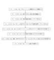
図1~図3に示すように、完全なロボットアームの動力学方程式には、慣性項、遠心力及びコリオリ力項、重力項と摩擦力項が含まれている。なお、慣性項は関節加速度に関係し、遠心力及びコリオリ力項は関節速度に関係し、摩擦力項も関節速度に関係するが、関節加速度及び関節速度は、ロボットアームが静的状態である時に何れもゼロであるので、静的位置に対する研究は、重力項だけに対して展開しても良い。重力項を含む動力学方程式を構築するには、ロボットアームの関節位置及びモーメントを入力とする必要があるので、ロボットアームのハードウェアに対してある程度の要求がある。KUKA LBR Med 7 R800を例とすれば、当該ロボットアームは、7軸協調型ロボットアームであり、各関節には、高精度の位置センサー及びモーメントセンサーが装備されており、本願におけるロボットアームのハードウェアに対する配置要求を満たしている。KUKA LBR Med 7 R800の7軸協調型ロボットアームを例として挙げて実際の操作を説明する。 As shown in FIGS. 1-3, the complete robotic arm dynamics equation includes inertia terms, centrifugal and Coriolis force terms, gravitational terms and frictional force terms. The inertia term relates to joint acceleration, the centrifugal force and Coriolis force terms relate to joint velocity, and the friction force term also relates to joint velocity. Sometimes both are zero, so the study for static positions may be expanded for the gravitational term only. Since the joint positions and moments of the robot arm must be input to construct the dynamics equation including the gravitational term, there are certain demands on the hardware of the robot arm. Taking the KUKA LBR Med 7 R800 as an example, the robot arm is a 7-axis cooperative robot arm, each joint is equipped with a high-precision position sensor and a moment sensor. Satisfies placement requirements for hardware. The actual operation will be explained using the KUKA LBR Med 7 R800 7-axis coordinated robot arm as an example.
ステップS1.1においては、ロボットアームの運動学モデルを構築する。 In step S1.1, a kinematic model of the robot arm is constructed.
本実施例の1つの可能な実現方法においては、ロボットアームの運動学モデルを構築する際、ロボットアームの関節座標系の構築は、古典的なD-H法(A Kinematic Notation for Lower-Pair Mechanisms Based on Matrices, J.Denavit,R.S.Hartenberg)を採用する。KUKA LBR Med 7 R800については、そのD-Hパラメータ表は、次の通りである。 In one possible implementation of this embodiment, when constructing the kinematic model of the robot arm, the construction of the joint coordinate system of the robot arm is based on the classical DH method (A Kinematic Notation for Lower-Pair Mechanisms). Based on Matrices, J. Denavit, RS Hartenberg). For the KUKA LBR Med 7 R800, the DH parameter table is as follows.

ステップS1.2においては、動力学モデルの重力項を再構築する。 In step S1.2, the gravitational term of the dynamics model is reconstructed.
本実施例においては、静的状態のロケットアームは、重力項がロケットアームの関節モーメントに等しく、式は、次のように表される。

ステップS1.3においては、無負荷静的位置サンプリングをする。 In step S1.3, no-load static position sampling is performed.
本実施例においては、ロケットアームが無負荷状態であることを確認し、ロケットアームを作業空間の非特異位置に移動させ、各関節の静止後に関節の位置及びモーメントを収集する。サンプリングポイントが作業空間全体にできるだけ広がるように、サンプリングのステップを繰り返す。サンプリング過程においては、僅かのサンプリングポイントが特異位置に非常に接近する場合があるが、特異位置が原因で、ロケットアームの自由度の不足により、モーメントのフィードバックが不正確であることを招くので、これらのサンプリングポイントがサンプリングセットから除去されるべきである。 In this example, the rocket arm is verified to be unloaded, the rocket arm is moved to a non-singular position in the workspace, and the joint positions and moments are collected after each joint rests. The sampling step is repeated so that the sampling points are spread as far as possible over the working space. In the sampling process, a few sampling points may be very close to the singular position, but due to the singular position, the lack of freedom of the rocket arm will lead to inaccurate feedback of the moment. These sampling points should be removed from the sampling set.
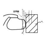
図3に示すように、ステップS1.4においては、各ツールを取り付けた後にそれぞれ静的位置サンプリングをする。 As shown in FIG. 3, in step S1.4, static position sampling is performed after each tool is installed.
本実施例においては、順に各ツールをロケットアームの末端に取り付け、ステップS1.3を繰り返して各ツールごとに対して1ラウンドのモーションサンプリングを実行し、特異位置を除去した後のデータセットを保存する。ツール自体が一定のサイズを持っているため、ロボットアームの運動範囲に対してある程度の制限を与え、運動過程においては、ロボットアーム本体又は周囲の障害物と衝突する事故が発生する可能性があるので、ツールとロボットアームの静的位置をサンプリングする過程においては、有効的な作業空間を再確認し、合理的な運動軌跡を設計し、サンプリングポイントをできるだけ作業空間に広がりながら、衝突の発生を防止する必要がある。よって、本実施例の1つ可能な実現方法では、各ツールについて、当該ツールがロボットアームの末端に取り付けられた後、当該ツールのサイズに基づいてロボットアームの現在の当該ツールに対応する有効的な作業空間を決定し、有効的な作業空間に基づいてステップS1.3を繰り返して当該ツールに対して静的位置サンプリングを行う。 In this example, each tool is attached to the end of the rocket arm in turn, step S1.3 is repeated to perform one round of motion sampling for each tool, and save the data set after singular positions are removed. do. Since the tool itself has a certain size, it limits the range of movement of the robot arm to some extent, and during the movement process, there is a possibility of collision with the robot arm body or surrounding obstacles. Therefore, in the process of sampling the static positions of the tool and robot arm, reconfirm the effective working space, design a rational motion trajectory, spread the sampling points as much as possible in the working space, and prevent the occurrence of collisions. must be prevented. Thus, in one possible implementation of this embodiment, for each tool, after the tool is attached to the distal end of the robot arm, an effective number corresponding to the current tool on the robot arm is assigned based on the size of the tool. Then, based on the valid workspace, step S1.3 is repeated to perform static position sampling for the tool.
ステップS1.5においては、各ツールのキャリブレーション待ちのパラメータ値をそれぞれ計算する。 In step S1.5, the parameter values awaiting calibration for each tool are calculated respectively.
本実施例においては、ステップS1.5を実行するために、収集された全てのデータをツールに基づいてグループ化し、以下に示すように、各グループのデータをステップS1.2で得られた方程式系に積み上げる必要がある。


ΣX=B
上述した式においては、Σは、対角行列であり、対角要素は、全て行列
ΣX=B
In the above equation, Σ is a diagonal matrix, and the diagonal elements are all matrices
ステップS1.6においては、各ツールの質量及び質量中心をそれぞれ計算する。 In step S1.6, the mass and center of mass of each tool are calculated respectively.
本実施例においては、ステップS1.5を実行するプロセスでは、剛体としてのツールをロボットアームの末端に設置してからパラメータのキャリブレーションを実行することが必要であるため、キャリブレーションされたパラメータにおける最後のセグメントの剛体の質量及び質量中心は、実際的には、ロボットアームの最後のセグメントとツールの結合後のパラメータである。よって、ツールの質量及び質量中心は、ツール付きのキャリブレーションされたパラメータと無負荷でキャリブレーションされたパラメータを比較し、ツールの質量及び質量中心とロボットアームのエンドセグメントアームの質量及び質量中心の関連関係を特徴付けるために用いられるマルチボディシステムの質量中心公式と組み合わせて決定することができる。故に、本実施例の1つの可能な実現方法では、各ツールについて、当該ツール携帯時にキャリブレーションされたパラメータ値と無負荷でキャリブレーションされたパラメータ値を比較し、比較結果および当該ツールの質量、当該ツールの質量中心、ロボットアームのエンドセグメントアームの質量及びエンドセグメントアームの質量中心の関連関係に基づき、当該ツールの質量及び質量中心を計算する。 In the present embodiment, the process of performing step S1.5 requires that the tool as a rigid body is installed at the end of the robot arm and then calibration of the parameters is performed. The mass and center of mass of the rigid body of the last segment are practically the post-coupling parameters of the last segment of the robot arm and the tool. The mass and center of mass of the tool are then compared with the calibrated parameters with the tool and the calibrated parameters with no load to determine the mass and center of mass of the tool and the end segment arm of the robot arm. It can be determined in combination with the multi-body system center-of-mass formula used to characterize the association relationship. Therefore, in one possible implementation of this embodiment, for each tool, the parameter values calibrated when the tool is carried and the parameter values calibrated without load are compared, and the comparison result and the mass of the tool, Based on the relationship between the center of mass of the tool, the mass of the end segment arm of the robot arm, and the center of mass of the end segment arm, the mass and center of mass of the tool are calculated.
なお、KUKA LBR Med 7 R800の末端を例として挙げ、図2に示すように、ツールをクランプした後のロボットアームシステムに対応するマルチボディシステムの質量中心公式は、次の物理的な特性がある。
また、本願は、ツールのパラメータを自動的に選択し、重力補償に用いるシステムを設計した。当該システムは、関節モーメント及び位置センサーの出力をシステムの入力とし、システムの内部において現在ツールによりロボットアームの末端に加えられている力を計算することで、クランプしているツールのタイプを判断する。次に、S1で計算されたパラメータを適用して重力補償を完成する。以下、実施のステップを詳しく説明する。 The present application also designed a system that automatically selects tool parameters and uses it for gravity compensation. The system determines the type of tool being clamped by taking the output of the joint moment and position sensors as input to the system and calculating the force currently being applied by the tool to the end of the robot arm inside the system. . Then, the parameters calculated in S1 are applied to complete gravity compensation. The implementation steps are described in detail below.
ステップS2.1においては、現在取り付けられているツールによりフランジ(ロボットアームの末端)に加えられる力を計算する。 In step S2.1, the force exerted on the flange (end of robot arm) by the currently mounted tool is calculated.
本実施例においては、無負荷状態でキャリブレーションされたパラメータを用いることができ、現在位置におけるロボットアーム本体により生じる関節モーメントτrobotを計算することができる。リアルタイムで測定された関節モーメントτmeasureをτrobotと減算をさせ、外力による関節モーメントτextを取得する。ヤコビ行列を用いて外力を関節空間から作業空間にマッピングし、作業空間におけるロボットアームの末端(フランジ)にかかる外力を計算することができる。In this embodiment, parameters calibrated in the unloaded state can be used to calculate the joint moment τrobot produced by the robot arm body at the current position. The joint moment τmeasure measured in real time is subtracted from τrobot to obtain the joint moment τext due to the external force. The Jacobian matrix can be used to map the external forces from the joint space to the work space and calculate the external forces on the distal end (flange) of the robot arm in the work space.
ステップS2.2においては、ツールの重力を補償する。 In step S2.2, the gravity of the tool is compensated.
本実施例においては、ツール間の違いが外力の値に反映される。例えば、工具間の質量差が大きい場合、外力のXYZ方向の値を、工具の識別基準として用いることができる。ツール間の質量差が小さく、質量中心の差が比較的大きい場合、外力のABC方向のトルクを識別基準とすることが考えられる。質量及び質量中心の差が何れも大きくない場合、それらを1つのツールとして見なし、同じセットのキャリブレーションされたパラメータを適用すれば、同様に比較的に良い補償効果を得ることができる。ツールのパラメータを入力して重力補正を自動的に行うロボットアームの場合、ステップS1.6で計算されたツールの質量と質量中心を、ロボットアームの配置に直接的に書き込み、ロボットアームの組み込みプログラムでツールにかかる外力を計算させることができる。重力補償機能のないロボットアームの場合、ステップS1.5でキャリブレーションされたパラメータを直接的に用いて現在ツールにかかる外力を計算することができる。よって、ロボットアームが感じる外力は、ツールの重力を補償した後の外力であり、当該外力を入力とする制御戦略もツールの影響を省略し、即ち、ゼロフォース制御を実現することができる。 In this example, differences between tools are reflected in the external force values. For example, when the mass difference between tools is large, the values of the external force in the XYZ directions can be used as the tool identification criteria. When the difference in mass between tools is small and the difference in the center of mass is relatively large, it is conceivable to use the torque of the external force in the ABC directions as the discrimination criterion. If the difference between the mass and the center of mass are both not large, then if we regard them as one tool and apply the same set of calibrated parameters, we can get a relatively good compensation effect as well. For a robot arm that automatically performs gravity correction by inputting tool parameters, the mass and center of mass of the tool calculated in step S1.6 are directly written into the robot arm configuration, and the robot arm built-in program can be used to calculate the external force applied to the tool. For a robot arm without gravity compensation function, the parameters calibrated in step S1.5 can be directly used to calculate the external force currently applied to the tool. Therefore, the external force felt by the robot arm is the external force after compensating for the gravity of the tool, and the control strategy using the external force as input also omits the influence of the tool, that is, can realize zero force control.
また、図4に示すように、本願は、ロボットアームの多負荷適応重力補償装置100を更に提供し、当該多負荷適応重力補償装置100に含まれる様々な機能実現モジュールにより、上述したロボットアームの多負荷適応型重力補償方法を実行する。なお、前記多負荷適応重力補償装置100は、モデル構築モジュール110、重力再構築モジュール120、位置サンプリングモジュール130、パラメータキャリブレーションモジュール140、質量パラメータ計算モジュール150、外力計算モジュール160及び重力補償モジュール170を備える。 In addition, as shown in FIG. 4 , the present application further provides a multi-load adaptive
モデル構築モジュール110は、ロボットアームの運動学モデルを構築するように配置されている。 A
重力再構築モジュール120は、動力学モデルの重力項を再構築するように配置されている。 A
位置サンプリングモジュール130は、無負荷静的位置サンプリングをするように配置されている。 The
位置サンプリングモジュール130は、さらに、各ツールを取り付けた後にそれぞれ静的位置サンプリングをするように配置されている。
パラメータキャリブレーションモジュール140は、各ツールのキャリブレーション待ちのパラメータ値をそれぞれ計算するように配置されている。 A
質量パラメータ計算モジュール150は、各ツールの質量及び質量中心をそれぞれ計算するように配置されている。 A mass
外力計算モジュール160は、現在、取り付けられているツールによりフランジに加えられる力を計算するように配置されている。 The external
重力補償モジュール170は、ツールの重力を補償するように配置されている。 A
本実施例の1つの可能な実現方法においては、前記モデル構築モジュール110は、ロボットアームの運動学モデルを構築するプロセスにおいて、標準D-H法を用いてロボットアームの関節座標系を構築する。 In one possible implementation of this embodiment, the
本実施例の1つの可能な実現方法においては、前記位置サンプリングモジュール130は、ロボットアームが無負荷の状況で、ロボットアームを作業空間内の任意の非特異位置に移動するように制御し、関節の位置及びモーメントの読み取り値をサンプリングする。 In one possible implementation of this embodiment, the
本実施例の1つの可能な実現方法においては、前記位置サンプリングモジュール130は、各ツールを何回かに分けて(ツール毎の順次に)ロボットアームの末端に取り付けた後、各ツール毎につき、当該ツールのサイズに基づいて当該ツールに対応するロボットアームの現在の有効な作業空間を決定し、次に、有効な作業空間に基づき、ロボットアームが有効な作業空間内の任意の非特異位置に移動するように繰り返して制御し、関節の位置及びモーメントの読み取り値をサンプリングする。 In one possible implementation of this embodiment, the
本実施例の1つの可能な実現方法においては、前記パラメータキャリブレーションモジュール140は、前記位置サンプリングモジュールにより得られたサンプリングデータを、ツールに基づいてグループ化し、順に前記重力再構築モジュールにより得られた重力項に代入して計算することで、各ツールのキャリブレーション待ちのパラメータ値を取得する。 In one possible implementation of this embodiment, the
なお、本願の実施例による多負荷適応重力補償装置100は、その基本原理及び技術的な効果は、前記多負荷適応重力補償方法と同じである。説明を簡潔にするために、本実施例で言及されていない部分については、前記多負荷適応重力補償方法の説明内容を参照することができる。 The basic principle and technical effects of the multi-load adaptive
また、本願は、ロボットアームの制御デバイスを更に提供し、当該制御デバイスは、メモリ及びプロセッサを備える。なお、前記メモリは、1つ又は複数のコンピュータプログラム製品を含むことができ、前記コンピュータプログラム製品は、揮発性メモリ及び/又は不揮発性メモリ等のような、様々なタイプの読み取り可能な記憶媒体を含むことができる。前記揮発性メモリは、例えば、ランダムアクセスメモリ及び/又はキャッシュメモリ等を含むことができる。前記不揮発性メモリは、例えば、リードオンリーメモリ、ハードディスク、フラッシュメモリ等を含むことができる。前記読み取り可能な記憶媒体には、1つ又は複数のコンピュータプログラムを記憶することができる。プロセッサは、前記コンピュータプログラムを実行することにより、前記ロボットアームの多負荷適応重力補償方法により表される機能及び/又は他の所望の機能を実現することができる。前記読み取り可能な記憶媒体には、さらに様々なアプリケーションプログラム及び様々なデータを記憶することができ、例えば、前記アプリケーションプログラムが使用及び/又は生成された様々なデータ等である。 Also, the present application further provides a control device for a robot arm, the control device comprising a memory and a processor. It should be noted that the memory may include one or more computer program products, which may include various types of readable storage media such as volatile memory and/or non-volatile memory. can contain. The volatile memory can include, for example, random access memory and/or cache memory. The non-volatile memory can include, for example, read-only memory, hard disk, flash memory, and the like. The readable storage medium can store one or more computer programs. A processor may implement the functions represented by the multi-load adaptive gravity compensation method for the robotic arm and/or other desired functions by executing the computer program. The readable storage medium can further store various application programs and various data, such as various data used and/or generated by the application programs.
前記プロセッサは、デジタル信号プロセッサ、フィールドプログラマブルゲートアレイ及びプログラマブルロジックアレイのうちの少なくとも1つのハードウェアの形で実現することができる。前記プロセッサは、中央処理ユニット、又は、データ処理機能及び/又は命令実行機能を有する他の形の処理ユニットの中の1つ又は複数の組み合わせであってもよく、所望の機能を実行するように、前記制御デバイスの中の他のアセンブリを制御することができる。前記プロセッサは、コンピュータプログラムが表す機能を実現するように、前記メモリに記憶されている当該コンピュータプログラムを相応的に実行することができる。 The processor may be implemented in hardware of at least one of a digital signal processor, a field programmable gate array and a programmable logic array. The processor may be a central processing unit or a combination of one or more among other forms of processing units having data processing capabilities and/or instruction execution capabilities, so as to perform the desired functions. , can control other assemblies in said control device. The processor is capable of correspondingly executing the computer program stored in the memory to perform the functions represented by the computer program.
本実施例の1つの可能な実現方法においては、前記ロボットアームの多負荷適応重力補償装置100は、ソフトウェア又はファームウェアの形で前記制御デバイスのメモリに記憶してもよく、前記制御デバイスのプロセッサにより、前記メモリの中の前記多負荷適応重力補償装置100に含まれるソフトウェア機能モジュールおよびコンピュータプログラム等を実行することにより、前記ロボットアームの多負荷適応重力補償方法に対応する機能を実現する。 In one possible implementation of this embodiment, the multi-load
上述したように、前記方案は、D-H法によりロボットアームの関節座標系を構築し、次に、関節座標系に基づいて各セグメントのロボットアームの質量中心位置に対して座標系構築を行う。元の重力項では、関節位置に関係する項目と質量中心に関係する項目を分割し、分割過程においてキャリブレーション待ちのパラメータを適切に組み合わせる必要があり、分割後の項目を2つの行列に入れ、それらの乗算が、元の重力項を依然として満たさせる。次に、無負荷状態でのロボットアームの静的位置をサンプリングし、その後に、各ツールをロボットアームの末端に取り付け、さらにそれぞれ静的位置サンプリングを行う。サンプリングされたデータをツールに基づいてグループ化した後、重力項に代入し、SVD分解を用いて組み合わせ後のパラメータの値を取得し、最後に組み合わせオブジェクトパラメータ分離の方法を用いて組み合わせ後のパラメータからツールの質量及び質量中心を抽出することができる。無負荷でキャリブレーションされたパラメータとリアルタイムの関節位置のフィードバックに基づき、現在取り付けられているエンドツールによりフランジに加えられる力の大きさを計算することができる。フランジでの外力を測定することにより、システムは、現在フランジにどのツールが取り付けられているかを知ることができるため、キャリブレーションされたパラメータ値を直接に用いてツールの重力を補償した後の外力測定を行うことができ、又は、得られた質量及び質量中心をロボットアームの配置に応用することができる。当該方法は、ツールパラメータを事前に計算して取得することにより、実際応用時の操作手順を簡素化し、協調作業の流暢さを大幅に高めることができる。また、関節位置及びモーメントセンサーを用いてツールに対してパラメータをキャリブレーションすることにより、キャリブレーションされたツールパラメータは、ロボットアームの運動学及び動力学の特徴をより適合し、ゼロフォース制御の性能を改善することができる。 As mentioned above, the method constructs the joint coordinate system of the robot arm by the DH method, and then constructs the coordinate system for the center of mass position of the robot arm of each segment according to the joint coordinate system. . In the original gravity term, it is necessary to divide the item related to the joint position and the item related to the center of mass, and properly combine the parameters awaiting calibration in the process of dividing. Their multiplication still causes the original gravitational term to be satisfied. Next, the static position of the robot arm under no load is sampled, after which each tool is attached to the end of the robot arm and each static position is sampled. After grouping the sampled data based on the tool, we impute the gravity term, use SVD decomposition to obtain the values of the combined parameters, and finally use the method of combined object parameter separation to obtain the values of the combined parameters The mass and center of mass of the tool can be extracted from . Based on no-load calibrated parameters and real-time joint position feedback, the magnitude of the force exerted by the currently installed end tool on the flange can be calculated. By measuring the external force at the flange, the system can know which tool is currently mounted on the flange, so the external force after compensating for the gravity of the tool using calibrated parameter values directly Measurements can be taken or the resulting mass and center of mass can be applied to the positioning of the robot arm. By pre-calculating and acquiring the tool parameters, the method can simplify the operating procedure in practical application and greatly enhance the fluency of collaborative work. In addition, by calibrating the parameters to the tool using joint position and moment sensors, the calibrated tool parameters better match the kinematics and dynamics characteristics of the robot arm, resulting in zero-force control performance. can be improved.
最後に、上述した実施例は、本願の技術案を説明するものに過ぎず、本願の保護範囲を限定するものではないことに留意されたい。選択可能な実現方法を参照して本願を詳しく説明したが、当業者は、本願の技術案の精神及び範囲から逸脱しない限り、本願の技術案に対して補正又は等価置換を行うことができることが理解されたい。 Finally, it should be noted that the above-mentioned embodiments are only for describing the technical solutions of the present application, and are not intended to limit the protection scope of the present application. Although the present application has been described in detail with reference to alternative implementations, those skilled in the art may make amendments or equivalent substitutions to the technical solution of the present application without departing from the spirit and scope of the technical solution of the present application. be understood.
本願の実施例は、ロボットアームの多負荷適応重力補償法、装置、制御デバイス及び読み取り可能な記憶媒体を提供し、D-H法によりロボットアームの関節座標系を構築し、次に、関節座標系に基づいて各セグメントのロボットアームの質量中心に対して座標系構築を行う。元の重力項では、関節位置に関係する項目と質量中心に関係する項目を分割し、分割過程においてキャリブレーション待ちのパラメータを適切に組み合わせる必要があり、さらに分割後の項目を2つの行列に入れ、それらの乗算が、元の重力項を依然として満たさせる。次に、無負荷状態でのロボットアームの静的位置をサンプリングし、その後に、各ツールをロボットアームの末端に取り付け、さらにそれぞれ静的位置サンプリングを行う。サンプリングされたデータをツールに基づいてグループ化した後、重力項に代入し、SVD分解を用いて組み合わせ後のパラメータの値を取得し、最後に組み合わせオブジェクトパラメータ分離の方法を用いて組み合わせ後のパラメータからツールの質量及び質量中心を抽出できる。無負荷でキャリブレーションされたパラメータとリアルタイムの関節位置のフィードバックに基づき、現在取り付けられているエンドツールによりフランジに加えられる力の大きさを計算することができる。算出されたフランジでの外力に基づいて、システムは、現在フランジにどのツールが取り付けられているかを知ることができるため、キャリブレーションされたパラメータ値を直接に用いてツールの重力を補償した後の外力測定を行うことができ、又は、得られた質量及び質量中心をロボットアームの配置に応用することができる。当該方法は、ツールパラメータを事前に計算して取得することにより、実際応用時の操作手順を簡素化し、協調作業の流暢さを大幅に高めることができる。また、関節位置及びモーメントセンサーを用いてツールに対してパラメータをキャリブレーションすることにより、キャリブレーションされたツールパラメータは、ロボットアームの運動学及び動力学の特徴をより適合し、ゼロフォース制御の性能を改善することができる。 Embodiments of the present application provide a multi-load adaptive gravity compensation method, apparatus, control device and readable storage medium for a robot arm, construct the joint coordinate system of the robot arm by the DH method, and then A coordinate system is constructed for the center of mass of the robot arm of each segment based on the system. In the original gravity term, it is necessary to split the terms related to the joint position and the terms related to the center of mass, appropriately combine the parameters awaiting calibration in the splitting process, and put the split terms into two matrices. , their multiplication still causes the original gravitational term to be satisfied. Next, the static position of the robot arm under no load is sampled, after which each tool is attached to the end of the robot arm and each static position is sampled. After grouping the sampled data based on the tool, we impute the gravity term, use SVD decomposition to obtain the values of the combined parameters, and finally use the method of combined object parameter separation to obtain the values of the combined parameters can extract the mass and center of mass of the tool from Based on no-load calibrated parameters and real-time joint position feedback, the magnitude of the force exerted by the currently installed end tool on the flange can be calculated. Based on the calculated external force on the flange, the system can know which tool is currently attached to the flange, so after compensating for tool gravity using the calibrated parameter values directly External force measurements can be taken or the resulting mass and center of mass can be applied to positioning the robot arm. By pre-calculating and acquiring the tool parameters, the method can simplify the operating procedure in practical application and greatly enhance the fluency of collaborative work. In addition, by calibrating the parameters to the tool using joint position and moment sensors, the calibrated tool parameters better match the kinematics and dynamics characteristics of the robot arm, resulting in zero-force control performance. can be improved.
Claims (15)
Translated fromJapanese動力学モデルの重力項を再構築するステップS1.2と、
無負荷静的位置サンプリングをするステップS1.3と、
各ツールを取り付けた後にそれぞれ静的位置サンプリングをするステップS1.4と、
各ツールのキャリブレーション待ちのパラメータ値をそれぞれ計算するステップS1.5と、
各ツールの質量及び質量中心をそれぞれ計算するステップS1.6と、
現在取り付けられているツールによりフランジに加えられる力を計算するステップS2.1と、
ツールの重力を補償するステップS2.2と、を備えることを特徴とするロボットアームの多負荷適応重力補償法。step S1.1 of building a kinematic model of the robot arm;
a step S1.2 of reconstructing the gravitational term of the dynamics model;
step S1.3 of no-load static position sampling;
a step S1.4 of static position sampling after mounting each tool;
step S1.5 of calculating respective parameter values awaiting calibration for each tool;
a step S1.6 of calculating the mass and center of mass of each tool respectively;
a step S2.1 of calculating the force exerted on the flange by the currently installed tool;
compensating for tool gravity S2.2.
動力学モデルの重力項を再構築するように配置されている重力再構築モジュールと、
無負荷静的位置サンプリングをするように配置されている位置サンプリングモジュールと、
ツールを取り付けた後に静的位置サンプリングをするようにさらに配置されている位置サンプリングモジュールと、
各ツールのキャリブレーション待ちのパラメータ値をそれぞれ計算するように配置されているパラメータキャリブレーションモジュールと、
各ツールの質量及び質量中心をそれぞれ計算するように配置されている質量パラメータ計算モジュールと、
現在取り付けられているツールによりフランジに加えられる力を計算するように配置されている外力計算モジュールと、
ツールの重力を補償するように配置されている重力補償モジュールと、を備えることを特徴とするロボットアームの多負荷適応重力補償装置。a model building module arranged to build a kinematic model of the robotic arm;
a gravity reconstruction module arranged to reconstruct the gravity term of the dynamics model;
a position sampling module arranged for no-load static position sampling;
a position sampling module further arranged to perform static position sampling after mounting the tool;
a parameter calibration module arranged to calculate respective calibration pending parameter values for each tool;
a mass parameter calculation module arranged to calculate the mass and center of mass of each tool respectively;
an external force calculation module arranged to calculate the force exerted on the flange by the currently installed tool;
a gravity compensation module arranged to compensate for tool gravity.
前記メモリには、前記プロセッサで実行することが可能なコンピュータプログラムを記憶しており、
前記プロセッサが前記コンピュータプログラムを実行すると、請求項1~7の何れか1つに記載のロボットアームの多負荷適応重力補償法を実現することを特徴とするロボットアームの制御デバイス。A robotic arm control device comprising a memory and a processor,
The memory stores a computer program executable by the processor,
A control device for a robot arm, wherein the multi-load adaptive gravity compensation method for a robot arm according to any one of claims 1 to 7 is realized when the processor executes the computer program.
前記コンピュータプログラムがプロセッサに実行されると、請求項1~7の何れか1つに記載のロボットアームの多負荷適応重力補償法を実行することを特徴とする読み取り可能な記憶媒体。A readable storage medium storing a computer program,
A readable storage medium characterized in that, when the computer program is executed by a processor, it performs the multi-load adaptive gravity compensation method for a robot arm according to any one of claims 1-7.
Applications Claiming Priority (3)
| Application Number | Priority Date | Filing Date | Title |
|---|---|---|---|
| CN202010466099.XACN111618857B (en) | 2020-05-28 | 2020-05-28 | A Multi-Load Adaptive Gravity Compensation Method for Manipulators |
| CN202010466099.X | 2020-05-28 | ||
| PCT/CN2020/124400WO2021238049A1 (en) | 2020-05-28 | 2020-10-28 | Method, apparatus and control device for multi-load self-adaptive gravity compensation of manipulator |
Publications (2)
| Publication Number | Publication Date |
|---|---|
| JP2023524897Atrue JP2023524897A (en) | 2023-06-13 |
| JP7437081B2 JP7437081B2 (en) | 2024-02-22 |
Family
ID=72256196
Family Applications (1)
| Application Number | Title | Priority Date | Filing Date |
|---|---|---|---|
| JP2022569139AActiveJP7437081B2 (en) | 2020-05-28 | 2020-10-28 | Multi-load adaptive gravity compensation method, apparatus and control device for robot arm |
Country Status (4)
| Country | Link |
|---|---|
| JP (1) | JP7437081B2 (en) |
| KR (1) | KR20230003233A (en) |
| CN (1) | CN111618857B (en) |
| WO (1) | WO2021238049A1 (en) |
Families Citing this family (25)
| Publication number | Priority date | Publication date | Assignee | Title |
|---|---|---|---|---|
| CN111618857B (en)* | 2020-05-28 | 2021-04-20 | 杭州键嘉机器人有限公司 | A Multi-Load Adaptive Gravity Compensation Method for Manipulators |
| CN112140111B (en)* | 2020-09-24 | 2022-08-19 | 珠海格力智能装备有限公司 | Method for determining center of mass of tail end load of robot |
| CN113768626B (en)* | 2020-09-25 | 2024-03-22 | 武汉联影智融医疗科技有限公司 | Surgical robot control method, computer device and surgical robot system |
| WO2022208414A1 (en) | 2021-03-31 | 2022-10-06 | Moon Surgical Sas | Co-manipulation surgical system for use with surgical instruments for performing laparoscopic surgery |
| US12042241B2 (en) | 2021-03-31 | 2024-07-23 | Moon Surgical Sas | Co-manipulation surgical system having automated preset robot arm configurations |
| US12167900B2 (en) | 2021-03-31 | 2024-12-17 | Moon Surgical Sas | Co-manipulation surgical system having automated preset robot arm configurations |
| US12178418B2 (en) | 2021-03-31 | 2024-12-31 | Moon Surgical Sas | Co-manipulation surgical system having a coupling mechanism removeably attachable to surgical instruments |
| US11812938B2 (en) | 2021-03-31 | 2023-11-14 | Moon Surgical Sas | Co-manipulation surgical system having a coupling mechanism removeably attachable to surgical instruments |
| CN113510698B (en)* | 2021-04-26 | 2022-07-29 | 深圳市优必选科技股份有限公司 | Mechanical arm control method and device, mechanical arm and readable storage medium |
| CN114296454B (en)* | 2021-12-24 | 2024-05-28 | 大连理工大学人工智能大连研究院 | Self-adaptive motion control method and system for omnidirectional full-drive mobile robot |
| CN114750148B (en)* | 2022-03-17 | 2024-05-17 | 广东工业大学 | A closed-loop zero-force control method and system for gravity adaptive measurement |
| CN115462830B (en)* | 2022-09-26 | 2025-08-15 | 武汉库柏特科技有限公司 | Manual dragging scanning method, device and equipment of ultrasonic scanning robot |
| CN115561004B (en)* | 2022-10-21 | 2023-04-18 | 哈尔滨工业大学 | Space multi-branch robot ground test platform and test method |
| CN115533916B (en)* | 2022-10-31 | 2024-10-15 | 广州大学 | A method, system, device and medium for identifying load mass at the end of a robotic arm |
| CN115778752B (en)* | 2022-11-24 | 2024-11-05 | 浙江工业大学 | Zero-force control method capable of inhibiting shake in sitting and lying type rehabilitation robot |
| CN115741718B (en)* | 2022-12-07 | 2024-06-07 | 江西省智能产业技术创新研究院 | Robot complete zero-force control method and system |
| CN115816461B (en)* | 2022-12-26 | 2023-10-24 | 睿尔曼智能科技(北京)有限公司 | A method for calculating the range of the robot arm's load center of mass and drawing the load curve |
| US11839442B1 (en)* | 2023-01-09 | 2023-12-12 | Moon Surgical Sas | Co-manipulation surgical system for use with surgical instruments for performing laparoscopic surgery while estimating hold force |
| US11986165B1 (en) | 2023-01-09 | 2024-05-21 | Moon Surgical Sas | Co-manipulation surgical system for use with surgical instruments for performing laparoscopic surgery while estimating hold force |
| US12370001B2 (en) | 2023-01-09 | 2025-07-29 | Moon Surgical Sas | Co-manipulation surgical system having automated user override detection |
| CN116442240B (en)* | 2023-05-26 | 2023-11-14 | 中山大学 | A zero-force control method and device for robots based on high-pass filter decoupling |
| CN116901087B (en)* | 2023-09-13 | 2023-11-17 | 真健康(北京)医疗科技有限公司 | Method and equipment for determining tail end force and moment of puncture operation robot |
| CN116922399B (en)* | 2023-09-15 | 2023-11-24 | 季华实验室 | Robotic arm gravity compensation method, device, electronic equipment and storage medium |
| CN119304884B (en)* | 2024-11-25 | 2025-08-08 | 广州龙之杰医疗科技有限公司 | A method, device, electronic device and storage medium for compensating load of a robotic arm |
| CN119635647B (en)* | 2024-12-26 | 2025-10-03 | 无锡奕帆微电子有限公司 | Robot, robotic arm, robotic arm detection control device and method thereof |
Citations (3)
| Publication number | Priority date | Publication date | Assignee | Title |
|---|---|---|---|---|
| JP2001526594A (en)* | 1997-03-04 | 2001-12-18 | エービービー アクチボラゲット | Determination method of load parameter in manipulator |
| JP2011519741A (en)* | 2008-05-08 | 2011-07-14 | クーカ・ロボター・ゲゼルシャフト・ミット・ベシュレンクテル・ハフツング | Medical robot and method for meeting performance requirements of medical robot |
| CN110666794A (en)* | 2019-09-25 | 2020-01-10 | 天津大学 | End load force compensation method for multi-DOF collaborative robot dragging |
Family Cites Families (11)
| Publication number | Priority date | Publication date | Assignee | Title |
|---|---|---|---|---|
| US5767648A (en)* | 1996-04-19 | 1998-06-16 | Massachusetts Institute Of Technology | Base force/torque sensor apparatus for the precise control of manipulators with joint friction and a method of use thereof |
| WO2009088828A1 (en)* | 2007-12-31 | 2009-07-16 | Abb Research Ltd. | Method and apparatus using a force sensor to provide load compensation for a robot |
| CN104626152B (en)* | 2013-11-14 | 2016-08-31 | 沈阳新松机器人自动化股份有限公司 | Industrial robot Active Compliance Control method and device |
| CN206216738U (en)* | 2016-10-17 | 2017-06-06 | 华南理工大学 | A kind of six-DOF robot end load dynamic parameters identification device |
| CN109746913B (en)* | 2018-12-29 | 2022-03-15 | 深圳市大象机器人科技有限公司 | Method and system for teaching robot posture keeping dragging |
| CN109676607B (en)* | 2018-12-30 | 2021-10-29 | 江苏集萃智能制造技术研究所有限公司 | A Zero-Gravity Control Method Without Torque Sensing |
| CN110193829B (en)* | 2019-04-24 | 2020-04-07 | 南京航空航天大学 | Robot precision control method for coupling kinematics and rigidity parameter identification |
| CN110103229B (en)* | 2019-06-06 | 2022-09-13 | 上海电气集团股份有限公司 | Gravity compensation method and system for tool arranged at tail end of robot |
| CN110549333B (en)* | 2019-08-06 | 2022-03-29 | 天津大学 | Gravity compensation method for TriMule horizontal series-parallel robot |
| CN110561438B (en)* | 2019-09-19 | 2021-02-05 | 华中科技大学 | Industrial robot manpower/position compliance control method based on kinetic parameter identification |
| CN111618857B (en)* | 2020-05-28 | 2021-04-20 | 杭州键嘉机器人有限公司 | A Multi-Load Adaptive Gravity Compensation Method for Manipulators |
- 2020
- 2020-05-28CNCN202010466099.XApatent/CN111618857B/enactiveActive
- 2020-10-28JPJP2022569139Apatent/JP7437081B2/enactiveActive
- 2020-10-28WOPCT/CN2020/124400patent/WO2021238049A1/ennot_activeCeased
- 2020-10-28KRKR1020227042228Apatent/KR20230003233A/enactivePending
Patent Citations (3)
| Publication number | Priority date | Publication date | Assignee | Title |
|---|---|---|---|---|
| JP2001526594A (en)* | 1997-03-04 | 2001-12-18 | エービービー アクチボラゲット | Determination method of load parameter in manipulator |
| JP2011519741A (en)* | 2008-05-08 | 2011-07-14 | クーカ・ロボター・ゲゼルシャフト・ミット・ベシュレンクテル・ハフツング | Medical robot and method for meeting performance requirements of medical robot |
| CN110666794A (en)* | 2019-09-25 | 2020-01-10 | 天津大学 | End load force compensation method for multi-DOF collaborative robot dragging |
Also Published As
| Publication number | Publication date |
|---|---|
| CN111618857A (en) | 2020-09-04 |
| CN111618857B (en) | 2021-04-20 |
| WO2021238049A1 (en) | 2021-12-02 |
| JP7437081B2 (en) | 2024-02-22 |
| KR20230003233A (en) | 2023-01-05 |
Similar Documents
| Publication | Publication Date | Title |
|---|---|---|
| JP2023524897A (en) | Multiload Adaptive Gravity Compensation Method, Apparatus and Control Device for Robotic Arm | |
| CN107738254B (en) | A method and system for converting and calibrating a manipulator coordinate system | |
| Filion et al. | Robot calibration using a portable photogrammetry system | |
| CN110640747B (en) | Hand-eye calibration method and system for robot, electronic equipment and storage medium | |
| Zhou et al. | Simultaneous identification of joint compliance and kinematic parameters of industrial robots | |
| CN107703748B (en) | A static stiffness identification method for heavy-duty robots based on offset plate design | |
| Li et al. | Kinematic calibration of serial robot using dual quaternions | |
| WO2022227536A1 (en) | Robot arm control method and apparatus, and robot arm and readable storage medium | |
| WO2018196232A1 (en) | Method for automatically calibrating robot and end effector, and system | |
| CN109079787A (en) | The automatic hand and eye calibrating method of non-rigid robot neural network based | |
| CN113211445A (en) | Robot parameter calibration method, device, equipment and storage medium | |
| Wang et al. | A vision-based fully-automatic calibration method for hand-eye serial robot | |
| Hou et al. | Performance analysis and comprehensive index optimization of a new configuration of Stewart six-component force sensor | |
| Aliakbari et al. | Computer integrated work-space quality improvement of the C4 parallel robot CMM based on kinematic error model for using in intelligent measuring | |
| Wang et al. | Configuration bifurcations analysis of six degree-of-freedom symmetrical Stewart parallel mechanisms | |
| Hernández-Martínez et al. | Characterization of a cable-based parallel mechanism for measurement purposes# | |
| CN117387834B (en) | Force sensor calibration method, system, electronic equipment and storage medium | |
| Uchiyama et al. | Evaluation of the robot force sensor structure using singular value decomposition | |
| Roos et al. | Off-line programming of industrial robots—Adaptation of simulated user programs to the real environment | |
| CN113091670B (en) | Calibration device and calibration method for robot joint stiffness | |
| Dong et al. | Simulation-based comparison between two crane-bunk systems for loading work when considering energy-optimal motion planning | |
| Zhang et al. | A Low-Cost, Portable and Robust Calibration Method for Industrial Robot | |
| RU2813435C1 (en) | Method, device and control device for self-adaptive compensation of gravity of manipulator with several loads | |
| Lu et al. | Robot calibration using relative measurements | |
| Lippiello et al. | Interaction control of robot manipulators using force and vision |
Legal Events
| Date | Code | Title | Description |
|---|---|---|---|
| A621 | Written request for application examination | Free format text:JAPANESE INTERMEDIATE CODE: A621 Effective date:20221114 | |
| A131 | Notification of reasons for refusal | Free format text:JAPANESE INTERMEDIATE CODE: A131 Effective date:20230908 | |
| A521 | Request for written amendment filed | Free format text:JAPANESE INTERMEDIATE CODE: A523 Effective date:20231205 | |
| TRDD | Decision of grant or rejection written | ||
| A01 | Written decision to grant a patent or to grant a registration (utility model) | Free format text:JAPANESE INTERMEDIATE CODE: A01 Effective date:20240105 | |
| A61 | First payment of annual fees (during grant procedure) | Free format text:JAPANESE INTERMEDIATE CODE: A61 Effective date:20240202 | |
| R150 | Certificate of patent or registration of utility model | Ref document number:7437081 Country of ref document:JP Free format text:JAPANESE INTERMEDIATE CODE: R150 |