JP2023524042A - Devices and methods for accessing the intradural compartment and treating intracranial hematomas - Google Patents
Devices and methods for accessing the intradural compartment and treating intracranial hematomasDownload PDFInfo
- Publication number
- JP2023524042A JP2023524042AJP2022566079AJP2022566079AJP2023524042AJP 2023524042 AJP2023524042 AJP 2023524042AJP 2022566079 AJP2022566079 AJP 2022566079AJP 2022566079 AJP2022566079 AJP 2022566079AJP 2023524042 AJP2023524042 AJP 2023524042A
- Authority
- JP
- Japan
- Prior art keywords
- catheter
- shaft
- aspiration catheter
- lumen
- distal end
- Prior art date
- Legal status (The legal status is an assumption and is not a legal conclusion. Google has not performed a legal analysis and makes no representation as to the accuracy of the status listed.)
- Pending
Links
Images


Classifications
- A—HUMAN NECESSITIES
- A61—MEDICAL OR VETERINARY SCIENCE; HYGIENE
- A61B—DIAGNOSIS; SURGERY; IDENTIFICATION
- A61B17/00—Surgical instruments, devices or methods
- A61B17/0057—Implements for plugging an opening in the wall of a hollow or tubular organ, e.g. for sealing a vessel puncture or closing a cardiac septal defect
- A—HUMAN NECESSITIES
- A61—MEDICAL OR VETERINARY SCIENCE; HYGIENE
- A61B—DIAGNOSIS; SURGERY; IDENTIFICATION
- A61B17/00—Surgical instruments, devices or methods
- A61B17/12—Surgical instruments, devices or methods for ligaturing or otherwise compressing tubular parts of the body, e.g. blood vessels or umbilical cord
- A61B17/12022—Occluding by internal devices, e.g. balloons or releasable wires
- A61B17/12027—Type of occlusion
- A61B17/12031—Type of occlusion complete occlusion
- A—HUMAN NECESSITIES
- A61—MEDICAL OR VETERINARY SCIENCE; HYGIENE
- A61B—DIAGNOSIS; SURGERY; IDENTIFICATION
- A61B17/00—Surgical instruments, devices or methods
- A61B17/12—Surgical instruments, devices or methods for ligaturing or otherwise compressing tubular parts of the body, e.g. blood vessels or umbilical cord
- A61B17/12022—Occluding by internal devices, e.g. balloons or releasable wires
- A61B17/12099—Occluding by internal devices, e.g. balloons or releasable wires characterised by the location of the occluder
- A61B17/12109—Occluding by internal devices, e.g. balloons or releasable wires characterised by the location of the occluder in a blood vessel
- A—HUMAN NECESSITIES
- A61—MEDICAL OR VETERINARY SCIENCE; HYGIENE
- A61B—DIAGNOSIS; SURGERY; IDENTIFICATION
- A61B17/00—Surgical instruments, devices or methods
- A61B17/12—Surgical instruments, devices or methods for ligaturing or otherwise compressing tubular parts of the body, e.g. blood vessels or umbilical cord
- A61B17/12022—Occluding by internal devices, e.g. balloons or releasable wires
- A61B17/12131—Occluding by internal devices, e.g. balloons or releasable wires characterised by the type of occluding device
- A61B17/12181—Occluding by internal devices, e.g. balloons or releasable wires characterised by the type of occluding device formed by fluidized, gelatinous or cellular remodelable materials, e.g. embolic liquids, foams or extracellular matrices
- A61B17/12195—Occluding by internal devices, e.g. balloons or releasable wires characterised by the type of occluding device formed by fluidized, gelatinous or cellular remodelable materials, e.g. embolic liquids, foams or extracellular matrices comprising a curable material
- A—HUMAN NECESSITIES
- A61—MEDICAL OR VETERINARY SCIENCE; HYGIENE
- A61B—DIAGNOSIS; SURGERY; IDENTIFICATION
- A61B17/00—Surgical instruments, devices or methods
- A61B17/22—Implements for squeezing-off ulcers or the like on inner organs of the body; Implements for scraping-out cavities of body organs, e.g. bones; for invasive removal or destruction of calculus using mechanical vibrations; for removing obstructions in blood vessels, not otherwise provided for
- A—HUMAN NECESSITIES
- A61—MEDICAL OR VETERINARY SCIENCE; HYGIENE
- A61B—DIAGNOSIS; SURGERY; IDENTIFICATION
- A61B17/00—Surgical instruments, devices or methods
- A61B17/32—Surgical cutting instruments
- A61B17/320016—Endoscopic cutting instruments, e.g. arthroscopes, resectoscopes
- A—HUMAN NECESSITIES
- A61—MEDICAL OR VETERINARY SCIENCE; HYGIENE
- A61B—DIAGNOSIS; SURGERY; IDENTIFICATION
- A61B17/00—Surgical instruments, devices or methods
- A61B17/34—Trocars; Puncturing needles
- A61B17/3415—Trocars; Puncturing needles for introducing tubes or catheters, e.g. gastrostomy tubes, drain catheters
- A—HUMAN NECESSITIES
- A61—MEDICAL OR VETERINARY SCIENCE; HYGIENE
- A61B—DIAGNOSIS; SURGERY; IDENTIFICATION
- A61B17/00—Surgical instruments, devices or methods
- A61B17/34—Trocars; Puncturing needles
- A61B17/3478—Endoscopic needles, e.g. for infusion
- A—HUMAN NECESSITIES
- A61—MEDICAL OR VETERINARY SCIENCE; HYGIENE
- A61B—DIAGNOSIS; SURGERY; IDENTIFICATION
- A61B18/00—Surgical instruments, devices or methods for transferring non-mechanical forms of energy to or from the body
- A61B18/04—Surgical instruments, devices or methods for transferring non-mechanical forms of energy to or from the body by heating
- A61B18/12—Surgical instruments, devices or methods for transferring non-mechanical forms of energy to or from the body by heating by passing a current through the tissue to be heated, e.g. high-frequency current
- A61B18/14—Probes or electrodes therefor
- A61B18/1492—Probes or electrodes therefor having a flexible, catheter-like structure, e.g. for heart ablation
- A—HUMAN NECESSITIES
- A61—MEDICAL OR VETERINARY SCIENCE; HYGIENE
- A61B—DIAGNOSIS; SURGERY; IDENTIFICATION
- A61B5/00—Measuring for diagnostic purposes; Identification of persons
- A61B5/68—Arrangements of detecting, measuring or recording means, e.g. sensors, in relation to patient
- A61B5/6846—Arrangements of detecting, measuring or recording means, e.g. sensors, in relation to patient specially adapted to be brought in contact with an internal body part, i.e. invasive
- A61B5/6847—Arrangements of detecting, measuring or recording means, e.g. sensors, in relation to patient specially adapted to be brought in contact with an internal body part, i.e. invasive mounted on an invasive device
- A61B5/6852—Catheters
- A—HUMAN NECESSITIES
- A61—MEDICAL OR VETERINARY SCIENCE; HYGIENE
- A61M—DEVICES FOR INTRODUCING MEDIA INTO, OR ONTO, THE BODY; DEVICES FOR TRANSDUCING BODY MEDIA OR FOR TAKING MEDIA FROM THE BODY; DEVICES FOR PRODUCING OR ENDING SLEEP OR STUPOR
- A61M25/00—Catheters; Hollow probes
- A61M25/0067—Catheters; Hollow probes characterised by the distal end, e.g. tips
- A61M25/0082—Catheter tip comprising a tool
- A—HUMAN NECESSITIES
- A61—MEDICAL OR VETERINARY SCIENCE; HYGIENE
- A61B—DIAGNOSIS; SURGERY; IDENTIFICATION
- A61B17/00—Surgical instruments, devices or methods
- A61B2017/00017—Electrical control of surgical instruments
- A61B2017/00022—Sensing or detecting at the treatment site
- A61B2017/00084—Temperature
- A—HUMAN NECESSITIES
- A61—MEDICAL OR VETERINARY SCIENCE; HYGIENE
- A61B—DIAGNOSIS; SURGERY; IDENTIFICATION
- A61B17/00—Surgical instruments, devices or methods
- A61B2017/00017—Electrical control of surgical instruments
- A61B2017/00115—Electrical control of surgical instruments with audible or visual output
- A61B2017/00128—Electrical control of surgical instruments with audible or visual output related to intensity or progress of surgical action
- A—HUMAN NECESSITIES
- A61—MEDICAL OR VETERINARY SCIENCE; HYGIENE
- A61B—DIAGNOSIS; SURGERY; IDENTIFICATION
- A61B17/00—Surgical instruments, devices or methods
- A61B2017/00017—Electrical control of surgical instruments
- A61B2017/00137—Details of operation mode
- A61B2017/00141—Details of operation mode continuous, e.g. wave
- A61B2017/00146—Details of operation mode continuous, e.g. wave with multiple frequencies
- A—HUMAN NECESSITIES
- A61—MEDICAL OR VETERINARY SCIENCE; HYGIENE
- A61B—DIAGNOSIS; SURGERY; IDENTIFICATION
- A61B17/00—Surgical instruments, devices or methods
- A61B2017/00017—Electrical control of surgical instruments
- A61B2017/00137—Details of operation mode
- A61B2017/00154—Details of operation mode pulsed
- A—HUMAN NECESSITIES
- A61—MEDICAL OR VETERINARY SCIENCE; HYGIENE
- A61B—DIAGNOSIS; SURGERY; IDENTIFICATION
- A61B17/00—Surgical instruments, devices or methods
- A61B17/00234—Surgical instruments, devices or methods for minimally invasive surgery
- A61B2017/00292—Surgical instruments, devices or methods for minimally invasive surgery mounted on or guided by flexible, e.g. catheter-like, means
- A61B2017/003—Steerable
- A61B2017/00318—Steering mechanisms
- A61B2017/00323—Cables or rods
- A—HUMAN NECESSITIES
- A61—MEDICAL OR VETERINARY SCIENCE; HYGIENE
- A61B—DIAGNOSIS; SURGERY; IDENTIFICATION
- A61B17/00—Surgical instruments, devices or methods
- A61B17/00234—Surgical instruments, devices or methods for minimally invasive surgery
- A61B2017/00292—Surgical instruments, devices or methods for minimally invasive surgery mounted on or guided by flexible, e.g. catheter-like, means
- A61B2017/003—Steerable
- A61B2017/00318—Steering mechanisms
- A61B2017/00331—Steering mechanisms with preformed bends
- A—HUMAN NECESSITIES
- A61—MEDICAL OR VETERINARY SCIENCE; HYGIENE
- A61B—DIAGNOSIS; SURGERY; IDENTIFICATION
- A61B17/00—Surgical instruments, devices or methods
- A61B17/00234—Surgical instruments, devices or methods for minimally invasive surgery
- A61B2017/00292—Surgical instruments, devices or methods for minimally invasive surgery mounted on or guided by flexible, e.g. catheter-like, means
- A61B2017/00336—Surgical instruments, devices or methods for minimally invasive surgery mounted on or guided by flexible, e.g. catheter-like, means with a protective sleeve, e.g. retractable or slidable
- A—HUMAN NECESSITIES
- A61—MEDICAL OR VETERINARY SCIENCE; HYGIENE
- A61B—DIAGNOSIS; SURGERY; IDENTIFICATION
- A61B17/00—Surgical instruments, devices or methods
- A61B17/0057—Implements for plugging an opening in the wall of a hollow or tubular organ, e.g. for sealing a vessel puncture or closing a cardiac septal defect
- A61B2017/00575—Implements for plugging an opening in the wall of a hollow or tubular organ, e.g. for sealing a vessel puncture or closing a cardiac septal defect for closure at remote site, e.g. closing atrial septum defects
- A61B2017/00592—Elastic or resilient implements
- A—HUMAN NECESSITIES
- A61—MEDICAL OR VETERINARY SCIENCE; HYGIENE
- A61B—DIAGNOSIS; SURGERY; IDENTIFICATION
- A61B17/00—Surgical instruments, devices or methods
- A61B17/0057—Implements for plugging an opening in the wall of a hollow or tubular organ, e.g. for sealing a vessel puncture or closing a cardiac septal defect
- A61B2017/00646—Type of implements
- A61B2017/0065—Type of implements the implement being an adhesive
- A—HUMAN NECESSITIES
- A61—MEDICAL OR VETERINARY SCIENCE; HYGIENE
- A61B—DIAGNOSIS; SURGERY; IDENTIFICATION
- A61B17/00—Surgical instruments, devices or methods
- A61B2017/00681—Aspects not otherwise provided for
- A61B2017/00685—Archimedes screw
- A—HUMAN NECESSITIES
- A61—MEDICAL OR VETERINARY SCIENCE; HYGIENE
- A61B—DIAGNOSIS; SURGERY; IDENTIFICATION
- A61B17/00—Surgical instruments, devices or methods
- A61B2017/00831—Material properties
- A61B2017/00867—Material properties shape memory effect
- A—HUMAN NECESSITIES
- A61—MEDICAL OR VETERINARY SCIENCE; HYGIENE
- A61B—DIAGNOSIS; SURGERY; IDENTIFICATION
- A61B17/00—Surgical instruments, devices or methods
- A61B17/12—Surgical instruments, devices or methods for ligaturing or otherwise compressing tubular parts of the body, e.g. blood vessels or umbilical cord
- A61B2017/12004—Surgical instruments, devices or methods for ligaturing or otherwise compressing tubular parts of the body, e.g. blood vessels or umbilical cord for haemostasis, for prevention of bleeding
- A—HUMAN NECESSITIES
- A61—MEDICAL OR VETERINARY SCIENCE; HYGIENE
- A61B—DIAGNOSIS; SURGERY; IDENTIFICATION
- A61B17/00—Surgical instruments, devices or methods
- A61B17/12—Surgical instruments, devices or methods for ligaturing or otherwise compressing tubular parts of the body, e.g. blood vessels or umbilical cord
- A61B17/12022—Occluding by internal devices, e.g. balloons or releasable wires
- A61B2017/1205—Introduction devices
- A—HUMAN NECESSITIES
- A61—MEDICAL OR VETERINARY SCIENCE; HYGIENE
- A61B—DIAGNOSIS; SURGERY; IDENTIFICATION
- A61B17/00—Surgical instruments, devices or methods
- A61B17/32—Surgical cutting instruments
- A61B17/320016—Endoscopic cutting instruments, e.g. arthroscopes, resectoscopes
- A61B2017/32004—Endoscopic cutting instruments, e.g. arthroscopes, resectoscopes having a laterally movable cutting member at its most distal end which remains within the contours of said end
- A—HUMAN NECESSITIES
- A61—MEDICAL OR VETERINARY SCIENCE; HYGIENE
- A61B—DIAGNOSIS; SURGERY; IDENTIFICATION
- A61B17/00—Surgical instruments, devices or methods
- A61B17/32—Surgical cutting instruments
- A61B17/3205—Excision instruments
- A61B17/3207—Atherectomy devices working by cutting or abrading; Similar devices specially adapted for non-vascular obstructions
- A61B17/320758—Atherectomy devices working by cutting or abrading; Similar devices specially adapted for non-vascular obstructions with a rotating cutting instrument, e.g. motor driven
- A61B2017/320775—Morcellators, impeller or propeller like means
- A—HUMAN NECESSITIES
- A61—MEDICAL OR VETERINARY SCIENCE; HYGIENE
- A61B—DIAGNOSIS; SURGERY; IDENTIFICATION
- A61B18/00—Surgical instruments, devices or methods for transferring non-mechanical forms of energy to or from the body
- A61B2018/00005—Cooling or heating of the probe or tissue immediately surrounding the probe
- A61B2018/00011—Cooling or heating of the probe or tissue immediately surrounding the probe with fluids
- A61B2018/00029—Cooling or heating of the probe or tissue immediately surrounding the probe with fluids open
- A—HUMAN NECESSITIES
- A61—MEDICAL OR VETERINARY SCIENCE; HYGIENE
- A61B—DIAGNOSIS; SURGERY; IDENTIFICATION
- A61B18/00—Surgical instruments, devices or methods for transferring non-mechanical forms of energy to or from the body
- A61B2018/00315—Surgical instruments, devices or methods for transferring non-mechanical forms of energy to or from the body for treatment of particular body parts
- A61B2018/00321—Head or parts thereof
- A—HUMAN NECESSITIES
- A61—MEDICAL OR VETERINARY SCIENCE; HYGIENE
- A61B—DIAGNOSIS; SURGERY; IDENTIFICATION
- A61B18/00—Surgical instruments, devices or methods for transferring non-mechanical forms of energy to or from the body
- A61B2018/00315—Surgical instruments, devices or methods for transferring non-mechanical forms of energy to or from the body for treatment of particular body parts
- A61B2018/00345—Vascular system
- A61B2018/00404—Blood vessels other than those in or around the heart
- A—HUMAN NECESSITIES
- A61—MEDICAL OR VETERINARY SCIENCE; HYGIENE
- A61B—DIAGNOSIS; SURGERY; IDENTIFICATION
- A61B18/00—Surgical instruments, devices or methods for transferring non-mechanical forms of energy to or from the body
- A61B2018/00315—Surgical instruments, devices or methods for transferring non-mechanical forms of energy to or from the body for treatment of particular body parts
- A61B2018/00434—Neural system
- A61B2018/00446—Brain
- A—HUMAN NECESSITIES
- A61—MEDICAL OR VETERINARY SCIENCE; HYGIENE
- A61B—DIAGNOSIS; SURGERY; IDENTIFICATION
- A61B18/00—Surgical instruments, devices or methods for transferring non-mechanical forms of energy to or from the body
- A61B2018/00571—Surgical instruments, devices or methods for transferring non-mechanical forms of energy to or from the body for achieving a particular surgical effect
- A61B2018/00577—Ablation
- A—HUMAN NECESSITIES
- A61—MEDICAL OR VETERINARY SCIENCE; HYGIENE
- A61B—DIAGNOSIS; SURGERY; IDENTIFICATION
- A61B18/00—Surgical instruments, devices or methods for transferring non-mechanical forms of energy to or from the body
- A61B2018/00571—Surgical instruments, devices or methods for transferring non-mechanical forms of energy to or from the body for achieving a particular surgical effect
- A61B2018/00601—Cutting
- A—HUMAN NECESSITIES
- A61—MEDICAL OR VETERINARY SCIENCE; HYGIENE
- A61B—DIAGNOSIS; SURGERY; IDENTIFICATION
- A61B18/00—Surgical instruments, devices or methods for transferring non-mechanical forms of energy to or from the body
- A61B2018/00636—Sensing and controlling the application of energy
- A61B2018/00696—Controlled or regulated parameters
- A61B2018/00702—Power or energy
- A—HUMAN NECESSITIES
- A61—MEDICAL OR VETERINARY SCIENCE; HYGIENE
- A61B—DIAGNOSIS; SURGERY; IDENTIFICATION
- A61B18/00—Surgical instruments, devices or methods for transferring non-mechanical forms of energy to or from the body
- A61B2018/00636—Sensing and controlling the application of energy
- A61B2018/00696—Controlled or regulated parameters
- A61B2018/00726—Duty cycle
- A—HUMAN NECESSITIES
- A61—MEDICAL OR VETERINARY SCIENCE; HYGIENE
- A61B—DIAGNOSIS; SURGERY; IDENTIFICATION
- A61B18/00—Surgical instruments, devices or methods for transferring non-mechanical forms of energy to or from the body
- A61B2018/00636—Sensing and controlling the application of energy
- A61B2018/00696—Controlled or regulated parameters
- A61B2018/00761—Duration
- A—HUMAN NECESSITIES
- A61—MEDICAL OR VETERINARY SCIENCE; HYGIENE
- A61B—DIAGNOSIS; SURGERY; IDENTIFICATION
- A61B18/00—Surgical instruments, devices or methods for transferring non-mechanical forms of energy to or from the body
- A61B2018/00636—Sensing and controlling the application of energy
- A61B2018/00696—Controlled or regulated parameters
- A61B2018/00767—Voltage
- A—HUMAN NECESSITIES
- A61—MEDICAL OR VETERINARY SCIENCE; HYGIENE
- A61B—DIAGNOSIS; SURGERY; IDENTIFICATION
- A61B18/00—Surgical instruments, devices or methods for transferring non-mechanical forms of energy to or from the body
- A61B2018/00636—Sensing and controlling the application of energy
- A61B2018/00773—Sensed parameters
- A61B2018/00791—Temperature
- A—HUMAN NECESSITIES
- A61—MEDICAL OR VETERINARY SCIENCE; HYGIENE
- A61B—DIAGNOSIS; SURGERY; IDENTIFICATION
- A61B18/00—Surgical instruments, devices or methods for transferring non-mechanical forms of energy to or from the body
- A61B2018/00636—Sensing and controlling the application of energy
- A61B2018/00773—Sensed parameters
- A61B2018/00875—Resistance or impedance
- A—HUMAN NECESSITIES
- A61—MEDICAL OR VETERINARY SCIENCE; HYGIENE
- A61B—DIAGNOSIS; SURGERY; IDENTIFICATION
- A61B18/00—Surgical instruments, devices or methods for transferring non-mechanical forms of energy to or from the body
- A61B18/04—Surgical instruments, devices or methods for transferring non-mechanical forms of energy to or from the body by heating
- A61B18/12—Surgical instruments, devices or methods for transferring non-mechanical forms of energy to or from the body by heating by passing a current through the tissue to be heated, e.g. high-frequency current
- A61B18/14—Probes or electrodes therefor
- A61B2018/1405—Electrodes having a specific shape
- A61B2018/1425—Needle
- A—HUMAN NECESSITIES
- A61—MEDICAL OR VETERINARY SCIENCE; HYGIENE
- A61B—DIAGNOSIS; SURGERY; IDENTIFICATION
- A61B18/00—Surgical instruments, devices or methods for transferring non-mechanical forms of energy to or from the body
- A61B18/04—Surgical instruments, devices or methods for transferring non-mechanical forms of energy to or from the body by heating
- A61B18/12—Surgical instruments, devices or methods for transferring non-mechanical forms of energy to or from the body by heating by passing a current through the tissue to be heated, e.g. high-frequency current
- A61B18/14—Probes or electrodes therefor
- A61B2018/1467—Probes or electrodes therefor using more than two electrodes on a single probe
- A—HUMAN NECESSITIES
- A61—MEDICAL OR VETERINARY SCIENCE; HYGIENE
- A61B—DIAGNOSIS; SURGERY; IDENTIFICATION
- A61B90/00—Instruments, implements or accessories specially adapted for surgery or diagnosis and not covered by any of the groups A61B1/00 - A61B50/00, e.g. for luxation treatment or for protecting wound edges
- A61B90/06—Measuring instruments not otherwise provided for
- A61B2090/064—Measuring instruments not otherwise provided for for measuring force, pressure or mechanical tension
- A61B2090/065—Measuring instruments not otherwise provided for for measuring force, pressure or mechanical tension for measuring contact or contact pressure
- A—HUMAN NECESSITIES
- A61—MEDICAL OR VETERINARY SCIENCE; HYGIENE
- A61B—DIAGNOSIS; SURGERY; IDENTIFICATION
- A61B90/00—Instruments, implements or accessories specially adapted for surgery or diagnosis and not covered by any of the groups A61B1/00 - A61B50/00, e.g. for luxation treatment or for protecting wound edges
- A61B90/36—Image-producing devices or illumination devices not otherwise provided for
- A61B90/37—Surgical systems with images on a monitor during operation
- A61B2090/373—Surgical systems with images on a monitor during operation using light, e.g. by using optical scanners
- A61B2090/3735—Optical coherence tomography [OCT]
- A—HUMAN NECESSITIES
- A61—MEDICAL OR VETERINARY SCIENCE; HYGIENE
- A61B—DIAGNOSIS; SURGERY; IDENTIFICATION
- A61B90/00—Instruments, implements or accessories specially adapted for surgery or diagnosis and not covered by any of the groups A61B1/00 - A61B50/00, e.g. for luxation treatment or for protecting wound edges
- A61B90/36—Image-producing devices or illumination devices not otherwise provided for
- A61B90/37—Surgical systems with images on a monitor during operation
- A61B2090/378—Surgical systems with images on a monitor during operation using ultrasound
- A61B2090/3782—Surgical systems with images on a monitor during operation using ultrasound transmitter or receiver in catheter or minimal invasive instrument
- A61B2090/3784—Surgical systems with images on a monitor during operation using ultrasound transmitter or receiver in catheter or minimal invasive instrument both receiver and transmitter being in the instrument or receiver being also transmitter
- A—HUMAN NECESSITIES
- A61—MEDICAL OR VETERINARY SCIENCE; HYGIENE
- A61B—DIAGNOSIS; SURGERY; IDENTIFICATION
- A61B2217/00—General characteristics of surgical instruments
- A61B2217/002—Auxiliary appliance
- A61B2217/005—Auxiliary appliance with suction drainage system
- A—HUMAN NECESSITIES
- A61—MEDICAL OR VETERINARY SCIENCE; HYGIENE
- A61B—DIAGNOSIS; SURGERY; IDENTIFICATION
- A61B2217/00—General characteristics of surgical instruments
- A61B2217/002—Auxiliary appliance
- A61B2217/007—Auxiliary appliance with irrigation system
- A—HUMAN NECESSITIES
- A61—MEDICAL OR VETERINARY SCIENCE; HYGIENE
- A61B—DIAGNOSIS; SURGERY; IDENTIFICATION
- A61B2218/00—Details of surgical instruments, devices or methods for transferring non-mechanical forms of energy to or from the body
- A61B2218/001—Details of surgical instruments, devices or methods for transferring non-mechanical forms of energy to or from the body having means for irrigation and/or aspiration of substances to and/or from the surgical site
- A61B2218/007—Aspiration
- A—HUMAN NECESSITIES
- A61—MEDICAL OR VETERINARY SCIENCE; HYGIENE
- A61B—DIAGNOSIS; SURGERY; IDENTIFICATION
- A61B5/00—Measuring for diagnostic purposes; Identification of persons
- A61B5/0059—Measuring for diagnostic purposes; Identification of persons using light, e.g. diagnosis by transillumination, diascopy, fluorescence
- A61B5/0073—Measuring for diagnostic purposes; Identification of persons using light, e.g. diagnosis by transillumination, diascopy, fluorescence by tomography, i.e. reconstruction of 3D images from 2D projections
- A—HUMAN NECESSITIES
- A61—MEDICAL OR VETERINARY SCIENCE; HYGIENE
- A61B—DIAGNOSIS; SURGERY; IDENTIFICATION
- A61B5/00—Measuring for diagnostic purposes; Identification of persons
- A61B5/0059—Measuring for diagnostic purposes; Identification of persons using light, e.g. diagnosis by transillumination, diascopy, fluorescence
- A61B5/0075—Measuring for diagnostic purposes; Identification of persons using light, e.g. diagnosis by transillumination, diascopy, fluorescence by spectroscopy, i.e. measuring spectra, e.g. Raman spectroscopy, infrared absorption spectroscopy
- A—HUMAN NECESSITIES
- A61—MEDICAL OR VETERINARY SCIENCE; HYGIENE
- A61B—DIAGNOSIS; SURGERY; IDENTIFICATION
- A61B5/00—Measuring for diagnostic purposes; Identification of persons
- A61B5/01—Measuring temperature of body parts ; Diagnostic temperature sensing, e.g. for malignant or inflamed tissue
- A—HUMAN NECESSITIES
- A61—MEDICAL OR VETERINARY SCIENCE; HYGIENE
- A61B—DIAGNOSIS; SURGERY; IDENTIFICATION
- A61B5/00—Measuring for diagnostic purposes; Identification of persons
- A61B5/05—Detecting, measuring or recording for diagnosis by means of electric currents or magnetic fields; Measuring using microwaves or radio waves
- A61B5/053—Measuring electrical impedance or conductance of a portion of the body
- A61B5/0538—Measuring electrical impedance or conductance of a portion of the body invasively, e.g. using a catheter
- A—HUMAN NECESSITIES
- A61—MEDICAL OR VETERINARY SCIENCE; HYGIENE
- A61B—DIAGNOSIS; SURGERY; IDENTIFICATION
- A61B5/00—Measuring for diagnostic purposes; Identification of persons
- A61B5/06—Devices, other than using radiation, for detecting or locating foreign bodies ; Determining position of diagnostic devices within or on the body of the patient
- A61B5/065—Determining position of the probe employing exclusively positioning means located on or in the probe, e.g. using position sensors arranged on the probe
- A—HUMAN NECESSITIES
- A61—MEDICAL OR VETERINARY SCIENCE; HYGIENE
- A61B—DIAGNOSIS; SURGERY; IDENTIFICATION
- A61B5/00—Measuring for diagnostic purposes; Identification of persons
- A61B5/24—Detecting, measuring or recording bioelectric or biomagnetic signals of the body or parts thereof
- A61B5/316—Modalities, i.e. specific diagnostic methods
- A61B5/369—Electroencephalography [EEG]
- A61B5/37—Intracranial electroencephalography [IC-EEG], e.g. electrocorticography [ECoG]
- A—HUMAN NECESSITIES
- A61—MEDICAL OR VETERINARY SCIENCE; HYGIENE
- A61B—DIAGNOSIS; SURGERY; IDENTIFICATION
- A61B5/00—Measuring for diagnostic purposes; Identification of persons
- A61B5/68—Arrangements of detecting, measuring or recording means, e.g. sensors, in relation to patient
- A61B5/6846—Arrangements of detecting, measuring or recording means, e.g. sensors, in relation to patient specially adapted to be brought in contact with an internal body part, i.e. invasive
- A61B5/6885—Monitoring or controlling sensor contact pressure
- A—HUMAN NECESSITIES
- A61—MEDICAL OR VETERINARY SCIENCE; HYGIENE
- A61B—DIAGNOSIS; SURGERY; IDENTIFICATION
- A61B6/00—Apparatus or devices for radiation diagnosis; Apparatus or devices for radiation diagnosis combined with radiation therapy equipment
- A61B6/02—Arrangements for diagnosis sequentially in different planes; Stereoscopic radiation diagnosis
- A61B6/03—Computed tomography [CT]
- A61B6/032—Transmission computed tomography [CT]
- A—HUMAN NECESSITIES
- A61—MEDICAL OR VETERINARY SCIENCE; HYGIENE
- A61B—DIAGNOSIS; SURGERY; IDENTIFICATION
- A61B6/00—Apparatus or devices for radiation diagnosis; Apparatus or devices for radiation diagnosis combined with radiation therapy equipment
- A61B6/12—Arrangements for detecting or locating foreign bodies
- A—HUMAN NECESSITIES
- A61—MEDICAL OR VETERINARY SCIENCE; HYGIENE
- A61B—DIAGNOSIS; SURGERY; IDENTIFICATION
- A61B6/00—Apparatus or devices for radiation diagnosis; Apparatus or devices for radiation diagnosis combined with radiation therapy equipment
- A61B6/48—Diagnostic techniques
- A61B6/481—Diagnostic techniques involving the use of contrast agents
- A—HUMAN NECESSITIES
- A61—MEDICAL OR VETERINARY SCIENCE; HYGIENE
- A61B—DIAGNOSIS; SURGERY; IDENTIFICATION
- A61B6/00—Apparatus or devices for radiation diagnosis; Apparatus or devices for radiation diagnosis combined with radiation therapy equipment
- A61B6/48—Diagnostic techniques
- A61B6/486—Diagnostic techniques involving generating temporal series of image data
- A61B6/487—Diagnostic techniques involving generating temporal series of image data involving fluoroscopy
- A—HUMAN NECESSITIES
- A61—MEDICAL OR VETERINARY SCIENCE; HYGIENE
- A61B—DIAGNOSIS; SURGERY; IDENTIFICATION
- A61B6/00—Apparatus or devices for radiation diagnosis; Apparatus or devices for radiation diagnosis combined with radiation therapy equipment
- A61B6/50—Apparatus or devices for radiation diagnosis; Apparatus or devices for radiation diagnosis combined with radiation therapy equipment specially adapted for specific body parts; specially adapted for specific clinical applications
- A61B6/501—Apparatus or devices for radiation diagnosis; Apparatus or devices for radiation diagnosis combined with radiation therapy equipment specially adapted for specific body parts; specially adapted for specific clinical applications for diagnosis of the head, e.g. neuroimaging or craniography
- A—HUMAN NECESSITIES
- A61—MEDICAL OR VETERINARY SCIENCE; HYGIENE
- A61B—DIAGNOSIS; SURGERY; IDENTIFICATION
- A61B6/00—Apparatus or devices for radiation diagnosis; Apparatus or devices for radiation diagnosis combined with radiation therapy equipment
- A61B6/50—Apparatus or devices for radiation diagnosis; Apparatus or devices for radiation diagnosis combined with radiation therapy equipment specially adapted for specific body parts; specially adapted for specific clinical applications
- A61B6/504—Apparatus or devices for radiation diagnosis; Apparatus or devices for radiation diagnosis combined with radiation therapy equipment specially adapted for specific body parts; specially adapted for specific clinical applications for diagnosis of blood vessels, e.g. by angiography
- A—HUMAN NECESSITIES
- A61—MEDICAL OR VETERINARY SCIENCE; HYGIENE
- A61B—DIAGNOSIS; SURGERY; IDENTIFICATION
- A61B8/00—Diagnosis using ultrasonic, sonic or infrasonic waves
- A61B8/08—Clinical applications
- A61B8/0808—Clinical applications for diagnosis of the brain
- A—HUMAN NECESSITIES
- A61—MEDICAL OR VETERINARY SCIENCE; HYGIENE
- A61B—DIAGNOSIS; SURGERY; IDENTIFICATION
- A61B8/00—Diagnosis using ultrasonic, sonic or infrasonic waves
- A61B8/08—Clinical applications
- A61B8/0891—Clinical applications for diagnosis of blood vessels
- A—HUMAN NECESSITIES
- A61—MEDICAL OR VETERINARY SCIENCE; HYGIENE
- A61B—DIAGNOSIS; SURGERY; IDENTIFICATION
- A61B8/00—Diagnosis using ultrasonic, sonic or infrasonic waves
- A61B8/48—Diagnostic techniques
- A61B8/488—Diagnostic techniques involving Doppler signals
- A—HUMAN NECESSITIES
- A61—MEDICAL OR VETERINARY SCIENCE; HYGIENE
- A61M—DEVICES FOR INTRODUCING MEDIA INTO, OR ONTO, THE BODY; DEVICES FOR TRANSDUCING BODY MEDIA OR FOR TAKING MEDIA FROM THE BODY; DEVICES FOR PRODUCING OR ENDING SLEEP OR STUPOR
- A61M25/00—Catheters; Hollow probes
- A61M25/0021—Catheters; Hollow probes characterised by the form of the tubing
- A61M2025/0042—Microcatheters, cannula or the like having outside diameters around 1 mm or less
- A—HUMAN NECESSITIES
- A61—MEDICAL OR VETERINARY SCIENCE; HYGIENE
- A61M—DEVICES FOR INTRODUCING MEDIA INTO, OR ONTO, THE BODY; DEVICES FOR TRANSDUCING BODY MEDIA OR FOR TAKING MEDIA FROM THE BODY; DEVICES FOR PRODUCING OR ENDING SLEEP OR STUPOR
- A61M2210/00—Anatomical parts of the body
- A61M2210/06—Head
- A61M2210/0693—Brain, cerebrum
- A—HUMAN NECESSITIES
- A61—MEDICAL OR VETERINARY SCIENCE; HYGIENE
- A61M—DEVICES FOR INTRODUCING MEDIA INTO, OR ONTO, THE BODY; DEVICES FOR TRANSDUCING BODY MEDIA OR FOR TAKING MEDIA FROM THE BODY; DEVICES FOR PRODUCING OR ENDING SLEEP OR STUPOR
- A61M25/00—Catheters; Hollow probes
- A61M25/0021—Catheters; Hollow probes characterised by the form of the tubing
- A61M25/0023—Catheters; Hollow probes characterised by the form of the tubing by the form of the lumen, e.g. cross-section, variable diameter
- A61M25/0026—Multi-lumen catheters with stationary elements
- A61M25/003—Multi-lumen catheters with stationary elements characterized by features relating to least one lumen located at the distal part of the catheter, e.g. filters, plugs or valves
- A—HUMAN NECESSITIES
- A61—MEDICAL OR VETERINARY SCIENCE; HYGIENE
- A61M—DEVICES FOR INTRODUCING MEDIA INTO, OR ONTO, THE BODY; DEVICES FOR TRANSDUCING BODY MEDIA OR FOR TAKING MEDIA FROM THE BODY; DEVICES FOR PRODUCING OR ENDING SLEEP OR STUPOR
- A61M25/00—Catheters; Hollow probes
- A61M25/0067—Catheters; Hollow probes characterised by the distal end, e.g. tips
- A61M25/0068—Static characteristics of the catheter tip, e.g. shape, atraumatic tip, curved tip or tip structure
- A61M25/007—Side holes, e.g. their profiles or arrangements; Provisions to keep side holes unblocked
- A—HUMAN NECESSITIES
- A61—MEDICAL OR VETERINARY SCIENCE; HYGIENE
- A61M—DEVICES FOR INTRODUCING MEDIA INTO, OR ONTO, THE BODY; DEVICES FOR TRANSDUCING BODY MEDIA OR FOR TAKING MEDIA FROM THE BODY; DEVICES FOR PRODUCING OR ENDING SLEEP OR STUPOR
- A61M25/00—Catheters; Hollow probes
- A61M25/0067—Catheters; Hollow probes characterised by the distal end, e.g. tips
- A61M25/0074—Dynamic characteristics of the catheter tip, e.g. openable, closable, expandable or deformable
- A—HUMAN NECESSITIES
- A61—MEDICAL OR VETERINARY SCIENCE; HYGIENE
- A61M—DEVICES FOR INTRODUCING MEDIA INTO, OR ONTO, THE BODY; DEVICES FOR TRANSDUCING BODY MEDIA OR FOR TAKING MEDIA FROM THE BODY; DEVICES FOR PRODUCING OR ENDING SLEEP OR STUPOR
- A61M27/00—Drainage appliance for wounds or the like, i.e. wound drains, implanted drains
- A—HUMAN NECESSITIES
- A61—MEDICAL OR VETERINARY SCIENCE; HYGIENE
- A61M—DEVICES FOR INTRODUCING MEDIA INTO, OR ONTO, THE BODY; DEVICES FOR TRANSDUCING BODY MEDIA OR FOR TAKING MEDIA FROM THE BODY; DEVICES FOR PRODUCING OR ENDING SLEEP OR STUPOR
- A61M39/00—Tubes, tube connectors, tube couplings, valves, access sites or the like, specially adapted for medical use
- A61M39/10—Tube connectors; Tube couplings
Landscapes
- Health & Medical Sciences (AREA)
- Life Sciences & Earth Sciences (AREA)
- Surgery (AREA)
- Engineering & Computer Science (AREA)
- Animal Behavior & Ethology (AREA)
- Public Health (AREA)
- General Health & Medical Sciences (AREA)
- Biomedical Technology (AREA)
- Heart & Thoracic Surgery (AREA)
- Veterinary Medicine (AREA)
- Medical Informatics (AREA)
- Molecular Biology (AREA)
- Nuclear Medicine, Radiotherapy & Molecular Imaging (AREA)
- Vascular Medicine (AREA)
- Reproductive Health (AREA)
- Otolaryngology (AREA)
- Cardiology (AREA)
- Physics & Mathematics (AREA)
- Pathology (AREA)
- Anesthesiology (AREA)
- Hematology (AREA)
- Plasma & Fusion (AREA)
- Biophysics (AREA)
- Orthopedic Medicine & Surgery (AREA)
- Pulmonology (AREA)
- Gastroenterology & Hepatology (AREA)
- Media Introduction/Drainage Providing Device (AREA)
- Medicines Containing Material From Animals Or Micro-Organisms (AREA)
- Materials For Medical Uses (AREA)
- Pharmaceuticals Containing Other Organic And Inorganic Compounds (AREA)
- Surgical Instruments (AREA)
- External Artificial Organs (AREA)
Abstract
Translated fromJapaneseDescription
Translated fromJapanese優先権の主張
本出願は、2020年4月28日出願の米国仮出願第63/016,613号の利益を主張し、その全体が参照により本明細書に組み込まれる。PRIORITY CLAIM This application claims the benefit of US Provisional Application No. 63/016,613, filed April 28, 2020, which is hereby incorporated by reference in its entirety.
本開示は、頭蓋内血腫の治療および経血管的アプローチから硬膜内区画へのアクセスのための装置および方法に関連する。例えば、本開示は、マルチモーダルカテーテルベースの技術を使用する、単一の血管内介入での、中硬膜動脈の塞栓および硬膜下血腫の排出のための装置および方法に関連する。 The present disclosure relates to devices and methods for treatment of intracranial hematomas and access to the intradural compartment from a transvascular approach. For example, the present disclosure relates to devices and methods for embolization of the middle meningeal artery and drainage of subdural hematomas in a single endovascular intervention using multimodal catheter-based techniques.
硬膜下血腫(SDH)は、脳の外側の血液の集まりで、一般的に頭部外傷から生じ、しばしば抗凝血剤と関連している。SDHは、入院を必要とする軽度~重度の頭部損傷の約11%、重度の外傷性脳損傷の約20%を悪化させる。外科的に排出されない場合、SDHは頭蓋骨内の圧力を増加させ、繊細な脳組織に損傷を与え、生命を脅かす可能性がある。最初は、急性SDH(aSDH)は主に硬い血餅によって形成されるが、その後数日で、血餅は粘性亜急性SDH(saSDH)へと漸進的に液化され、これが永続化して慢性SDH(cSDH)へと拡張する傾向がある。後者の病態は、高齢患者の脳萎縮および抗凝血剤の使用による抗凝固と関連しているため、高齢化集団における公衆衛生上の問題となっている。毎年、10万人のアメリカ人当たり約17~20人がcSDHの影響を受ける。これまで、cSDHは障害を引き起こす、致命的な疾患であり続けており、入院中の死亡率は16.7%、1年死亡率は32%、そして患者の21.1%のみが帰宅を認められた。 A subdural hematoma (SDH) is a collection of blood outside the brain, commonly resulting from a head injury, and is often associated with blood thinners. SDH exacerbates approximately 11% of mild to severe head injuries and approximately 20% of severe traumatic brain injuries requiring hospitalization. If not surgically drained, SDH can increase pressure within the skull, damage delicate brain tissue, and be life-threatening. Initially, acute SDH (aSDH) is formed primarily by hard clots, but over the next few days the clot progressively liquefies into viscous subacute SDH (saSDH), which persists and becomes chronic SDH ( cSDH). The latter condition is a public health problem in the aging population because it is associated with cerebral atrophy in elderly patients and anticoagulation through the use of anticoagulants. About 17-20 per 100,000 Americans are affected by cSDH each year. To date, cSDH remains a disabling, fatal disease, with an in-hospital mortality rate of 16.7%, a 1-year mortality rate of 32%, and only 21.1% of patients allowed to go home. was taken.
症候性SDHの標準治療は、外科手術による排出である。一般に、cSDHは比較的薄く、二つの穿頭孔で排出することができるが、saSDHおよびaSDHは粘性液体および/または血餅によって形成され、その排出は、開頭術と呼ばれる大きな骨の「窓」を利用する。開頭術は、cSDHの患者の10%超に影響を及ぼす慢性から急性のSDH(acSDH)で使用され、固形硬膜下血餅と混合した封入された液化血腫によって形成される。当初の外科手術による排出の有効性にもかかわらず、最大37%の失敗率のため懸念されている。治療が一度失敗し、患者が二度回目の外科的治療を受ける場合でも、さらなる再発は一般的であり、cSDHの再発は46%に達する可能性がある。 The standard treatment for symptomatic SDH is surgical drainage. In general, cSDH is relatively thin and can be drained by two burr holes, whereas saSDH and aSDH are formed by viscous fluid and/or blood clots, and their drainage is through a large bony "window" called a craniotomy. take advantage of Craniotomy is used in chronic to acute SDH (acSDH), which affects more than 10% of patients with cSDH, and is formed by an enclosed liquefied hematoma mixed with a solid subdural clot. Despite the effectiveness of initial surgical evacuation, there is concern due to failure rates of up to 37%. Even if treatment fails once and the patient undergoes a second surgical treatment, further recurrences are common, with cSDH recurrences potentially reaching 46%.
外科的排出は、通常、硬膜下腔へのドレーンの導入と組み合わされ、これは2~3日間、定位置にとどまる。この戦略は、ドレーンのない手術と比較して、再発率および6か月死亡率を約50%減少させると報告されたが、ドレーンは、脳損傷、新生膜からのさらなる出血、再発率を変化させることのない感染、および/または臨床転帰などの合併症をもたらす可能性がある。 Surgical drainage is usually combined with the introduction of a drain into the subdural space, which remains in place for 2-3 days. This strategy was reported to reduce recurrence and 6-month mortality by approximately 50% compared to surgery without drains, but drains reduced brain injury, further bleeding from neoplasia, and altered recurrence rates. may result in complications such as non-infectious infection and/or clinical outcome.
開放的外科的介入は、抗凝固剤および抗血小板剤の取り消しまたは中止を利用して、心血管周術期リスクを増加させる。開頭術には全身麻酔を伴うことがあり、これは他の併存疾患を有する高齢患者に特に危険である可能性がある。SDHの開頭術に関連する罹患率と死亡率は依然として高く、それぞれ25%および11%にもなると報告されている。 Open surgical interventions employ anticoagulant and antiplatelet withdrawal or discontinuation to increase cardiovascular perioperative risk. Craniotomy may involve general anesthesia, which can be especially dangerous for older patients with other comorbidities. Morbidity and mortality associated with craniotomy for SDH remain high, reportedly as high as 25% and 11%, respectively.
血管内中硬膜動脈(MMA)塞栓は、術後再発を低減するために使用される新たな血管内処置である。塞栓剤の注射の後、その後血腫はゆっくりと再吸収され、数週間から数か月の期間にわたって脳への質量効果を減少させる。MMA塞栓の症例シリーズのメタ分析では、従来の管理と比較して、塞栓後cSDHの再発率が低いことが報告されている(2.1%対27.7%、OR 087、95% CI0.026~0.292、P<0.001)。MMA塞栓は、aSDH、saSDH、およびacSDHを有する高リスク患者(すなわち、凝固障害または抗凝血剤を必要とする)におけるcSDHの治療および再発予防のための有望なアプローチである。 Intravascular middle meningeal artery (MMA) embolization is a new endovascular procedure used to reduce postoperative recurrence. After injection of embolic agents, the hematoma is then slowly resorbed, reducing the mass effect on the brain over a period of weeks to months. A meta-analysis of MMA embolization case series reported a lower recurrence rate of cSDH after embolization compared to conventional management (2.1% vs. 27.7%, OR 087, 95%
「ツーステップ」管理は効果的であるが(術前または術後補助としての血管内MMAによる急速な脳減圧のための外科的排出)、この戦略は、上述の手術のすべてのリスクおよび不快感を依然として担持し、二つの異なる処置を必要とする。これは、患者にとって不便であり、入院期間および回復時間を延長し、したがって、医療費を増大させる。SDH拡張を阻止し、かつ脳圧迫の即時軽減のためにSDHを排出するMMAの塞栓を可能にする完全血管内処置は、緊急の未だ満たされていない臨床ニーズである。 Although the 'two-step' management is effective (surgical evacuation for rapid cerebral decompression with intravascular MMA as preoperative or postoperative adjuvant), this strategy suffers from all the risks and discomforts of surgery described above. and require two different treatments. This is inconvenient for the patient, prolongs hospital stay and recovery time, and thus increases medical costs. A complete endovascular procedure that blocks SDH expansion and allows embolization of SDH-draining MMA for immediate relief of cerebral compression is an urgent unmet clinical need.
慢性SDHを治療する統合血管内アプローチは、同時のMMA塞栓および液体の排出を必要とする。MMAの解剖学的構造、cSDHの位置および粘度、およびMMAならびに基礎となる硬膜の動脈壁の強度を含む本明細書に記述の教示に基づいて、MMA塞栓および経動脈的cSDHは、本明細書に開示の装置および方法によって実行可能である。 An integrated endovascular approach to treat chronic SDH requires simultaneous MMA embolization and fluid drainage. Based on the teachings described herein, including the anatomy of the MMA, the location and viscosity of the cSDH, and the strength of the MMA and the underlying dural arterial wall, MMA embolization and transarterial cSDH are described herein. It can be implemented by the apparatus and methods disclosed in the publication.
急性、亜急性、および慢性から急性の、典型的にはSDHを排出する血管内アプローチは、MMAを収容できるものよりも大きい内腔を有するカテーテルを必要とする。さらに、MMAの塞栓は、cSDHと比較して重要性が低い。上矢状静脈洞の解剖学的構造および強度を含む本明細書に記載の教示に基づいて、横S状複合体および上錐体静脈洞、経静脈的SDH排出は、本明細書に開示の装置および方法によって実行可能である。 Acute, subacute, and chronic-to-acute endovascular approaches to drain SDH typically require catheters with lumens larger than can accommodate MMA. Moreover, embolization of MMA is of less importance compared to cSDH. Based on the teachings described herein, including the anatomy and strength of the superior sagittal sinus, the transverse sigmoid complex and the superior pyramidal sinus, transvenous SDH drainage, as disclosed herein. It can be performed by an apparatus and method.
頭蓋内区画への経動脈的および経静脈的アクセスのための装置および方法は、頭蓋内区画内の治療薬および装置の送達を可能にする。 Devices and methods for transarterial and transvenous access to the intracranial compartment enable delivery of therapeutic agents and devices within the intracranial compartment.
本開示は、硬膜内区画へのアクセスおよび硬膜下血腫の治療のための装置および方法を記載する。例えば、本開示は、マルチモーダルカテーテルベースの技術を使用する、単一の血管内介入での、中硬膜動脈の塞栓および慢性硬膜下血腫排出のための装置および方法を記載する。 The present disclosure describes devices and methods for accessing the intradural compartment and treating subdural hematomas. For example, the present disclosure describes devices and methods for middle meningeal artery embolization and chronic subdural hematoma drainage in a single endovascular intervention using multimodal catheter-based techniques.
本明細書では、末梢アプローチから頭蓋内静脈洞をナビゲートし、硬膜下血腫を排出するために硬膜内区画にアクセスする装置および方法が記載される。また、本明細書では、小脳テント上硬膜内区画への経血管的アクセスのための装置および方法が記載される。硬膜内区画は、硬膜下腔、拡張したくも膜下腔(例えば、槽)、脳組織、および脳室(例えば、脳内部の液体充填された空洞)から構成される。小脳テント上区画は、小脳テントの上の頭蓋内腔とみなされる。本明細書に開示される装置および方法はまた、経血管的アプローチからの硬膜上腔へのアクセスも記載する。 Described herein are devices and methods for navigating the intracranial sinus from a peripheral approach and accessing the intradural compartment for draining subdural hematomas. Also described herein are devices and methods for transvascular access to the cerebellar epitentorial intradural compartment. The intradural compartment consists of the subdural space, the expanded subarachnoid space (eg, the cisternae), brain tissue, and the ventricles (eg, fluid-filled cavities within the brain). The supratentorial compartment is considered the cranial cavity above the cerebellar tentorium. The devices and methods disclosed herein also describe access to the epidural space from a transvascular approach.
一態様では、本開示は、頭蓋内血管外液体、血栓、または粒子状物質の排出のためのシステムを対象とする。このシステムには、(i)第一の内腔を画定し、血管チャネルに挿入するように構成された遠位端部分を有する吸引カテーテル、(ii)第二の内腔を画定し、第一のルーメン内にスライド可能に配置可能なシャフト、拘束されていない時に湾曲した形状を有し、第一の内腔内に半径方向に拘束された時に直線形状を有するように可撓性のある、シャフトの遠位端部分、および(iii)第二の内腔内にスライド可能に可能で、中硬膜動脈の壁の貫通のために構成された傾斜先端を有するスタイレット、とが含まれる。 In one aspect, the present disclosure is directed to a system for evacuation of intracranial extravascular fluid, thrombus, or particulate matter. The system includes (i) an aspiration catheter defining a first lumen and having a distal end portion configured for insertion into a vascular channel; (ii) a second lumen defining a first lumen; a shaft slidably positionable within the lumen of the first lumen, flexible to have a curved shape when unconstrained and a straight shape when radially constrained within the first lumen; and (iii) a stylet slidably possible within the second lumen and having a beveled tip configured for penetration of the wall of the middle meningeal artery.
頭蓋内血管外液体、血栓、または粒子状物質の排出のためのかかるシステムは、任意に、以下の特徴のうちの一つまたは複数を含み得る。一部の実施形態では、システムはまた、第一の内腔内にスライド可能に配置可能で、かつ中硬膜動脈の分岐血管内への挿入のために構成された遠位端部分を有するマイクロカテーテルを含む。 Such systems for evacuation of intracranial extravascular fluid, thrombus, or particulate matter may optionally include one or more of the following features. In some embodiments, the system also includes a micrometer having a distal end portion slidably positionable within the first lumen and configured for insertion into a branch vessel of the middle meningeal artery. Including catheter.
別の態様では、本開示は、患者の硬膜下血腫の経動脈的排出のための方法を対象とする。方法には、(a)吸引カテーテルを、患者の脈管構造内で、吸引カテーテルの遠位端が患者の中硬膜動脈内に位置するまで前進させること、吸引カテーテルは第一の内腔を画定する、(b)第二の内腔を画定するシャフトおよび第二の内腔内のスタイレットを吸引カテーテルの第一の内腔を通って前進させること、(c)スタイレットの傾斜遠位端が、中硬膜動脈および硬膜の壁を通った穿刺を生成するように、第一および第二のルーメンの出口を越えて、スタイレットを遠位に前進させること、(d)シャフトの遠位端部分が自然な曲線形状を取るように、シャフトをスタイレットの上を、かつ穿刺を通って前進させること、(e)穿刺を通って吸引カテーテルを前進させること、(f)湾曲した形状を有する遠位先端部分を有するシャフトおよび吸引カテーテルを硬膜下血腫に向けて、吸引カテーテルの開放遠位端部分が硬膜下血腫内に入るまで前進させること、および(g)吸引カテーテルを使用して、真空およびあるいは他の血栓切除強化法を用いて、硬膜下血腫から液体を排出すること、とが含まれる。患者の硬膜下血腫のかかる排出方法は、任意に以下の特徴のうちの一つまたは複数を含み得る。方法はまた、(h)マイクロカテーテルの遠位端が中硬膜動脈内に位置するまで第一の内腔内にマイクロカテーテルを前進させること、および(i)動脈穿孔の前に一般的に実施される、中硬膜動脈を閉塞するためにマイクロカテーテルを介して塞栓性物質を注入すること、とを含んでもよい。一部の実施形態では、方法はまた、穿刺を通って延在する吸引カテーテル、シャフト、およびスタイレットを除去すること、および第一の内腔を通ってプラグ、コイルまたは粒子を送達して穿刺を遮断すること、とを含み得る。 In another aspect, the present disclosure is directed to a method for transarterial drainage of a subdural hematoma in a patient. The method includes: (a) advancing an aspiration catheter within the patient's vasculature until a distal end of the aspiration catheter is positioned within the patient's middle meningeal artery; (b) advancing a shaft defining a second lumen and a stylet within the second lumen through the first lumen of the aspiration catheter; (c) an angled distal portion of the stylet; advancing the stylet distally beyond the exit of the first and second lumens such that the ends create a puncture through the wall of the middle meningeal artery and dura; (d) the shaft; advancing the shaft over the stylet and through the puncture so that the distal end portion assumes a natural curved shape; (e) advancing the aspiration catheter through the puncture; advancing a shaft having a shaped distal tip portion and an aspiration catheter toward the subdural hematoma until the open distal end portion of the aspiration catheter is within the subdural hematoma; and (g) the aspiration catheter. Using vacuum and/or other thrombectomy enhancement methods to drain fluid from the subdural hematoma. Such methods of draining a patient's subdural hematoma may optionally include one or more of the following features. The method also includes (h) advancing the microcatheter within the first lumen until the distal end of the microcatheter is located within the middle meningeal artery, and (i) generally prior to arterial perforation. and injecting an embolic substance through the microcatheter to occlude the middle meningeal artery. In some embodiments, the method also includes removing the aspiration catheter, shaft, and stylet extending through the puncture, and delivering a plug, coil, or particle through the first lumen to penetrate the puncture. and blocking.
本明細書に記載の装置および方法は、頭蓋内区画へのアクセスを提供し、治療剤ならびに装置の永久的または一時的な送達、および複数の介入の実施を可能にし、a)硬膜を貫通して硬膜下腔に留まる、2)硬膜を貫通して硬膜下腔を横断し、くも膜下腔、脳組織および脳室に入る、といった特徴を含み得る。 The devices and methods described herein provide access to intracranial compartments, permit permanent or temporary delivery of therapeutic agents and devices, and the performance of multiple interventions, including: a) penetrating the dura mater; 2) penetrate the dura mater to traverse the subdural space and enter the subarachnoid space, brain tissue and ventricles.
別の態様では、本開示は、患者の硬膜下血腫の経静脈的排出のための方法を対象とする。方法には、(a)吸引カテーテルを、患者の脈管構造内で、吸引カテーテルの遠位端が頭蓋内静脈(上大脳静脈など)または硬膜静脈洞内に位置するまで前進させること、吸引カテーテルは第一の内腔を画定する、(b)第二の内腔を画定するシャフトおよび第二の内腔内のスタイレットを吸引カテーテルの第一の内腔を通って前進させること、(c)スタイレットの傾斜遠位端が、静脈および/または静脈洞の壁を通った穿刺を生成するように、第一および第二の内腔の出口を越えて、スタイレットを遠位に前進させること、(d)シャフトの遠位端部分が自然な曲線形状を取るように、シャフトをスタイレットの上を、かつ穿刺を通って前進させること、(e)穿刺を通って吸引カテーテルを前進させること、(f)湾曲した形状を有する遠位端部分を有するシャフトおよび吸引カテーテルを硬膜下血腫に向けて、吸引カテーテルの開放遠位端部分が硬膜下血腫内に入るまで前進させること、および(g)吸引カテーテルを使用して硬膜下血腫から液体を排出すること、とが含まれる。 In another aspect, the present disclosure is directed to a method for intravenous drainage of a subdural hematoma in a patient. The method includes (a) advancing an aspiration catheter through the patient's vasculature until the distal end of the aspiration catheter is located within an intracranial vein (such as the superior cerebral vein) or dural sinus; the catheter defines a first lumen; (b) advancing a shaft defining a second lumen and a stylet within the second lumen through the first lumen of the aspiration catheter; c) advancing the stylet distally past the exits of the first and second lumens such that the beveled distal end of the stylet creates a puncture through the wall of the vein and/or sinus (d) advancing the shaft over the stylet and through the puncture so that the distal end portion of the shaft assumes a natural curvilinear shape; (e) advancing the aspiration catheter through the puncture. (f) advancing a shaft having a distal end portion with a curved shape and an aspiration catheter toward the subdural hematoma until the open distal end portion of the aspiration catheter is within the subdural hematoma; and (g) draining fluid from the subdural hematoma using an aspiration catheter.
本書に記載の主題の特定の実施形態は、以下の利点のうちの一つまたは複数を実現するために実施することができる。第一に、中硬膜動脈の塞栓のための本明細書に記述された装置および方法は、術後の慢性硬膜下血腫の再発を低減するための有効な戦略を提供し、および慢性硬膜下血腫の主な治療法として、特に抗凝固療法または抗血小板療法が中断できない患者に有用である。本明細書に記載の血管内処置では、中硬膜動脈は塞栓されて、「漏れのある」膜への血液供給は減少し、慢性硬膜下血腫が排出され、手術で頭蓋骨を開頭することなく脳への質量効果が低下する。 Particular embodiments of the subject matter described herein can be implemented to achieve one or more of the following advantages. First, the devices and methods described herein for embolization of the middle meningeal artery provide an effective strategy for reducing the recurrence of postoperative chronic subdural hematoma and chronic dural hematoma. It is useful as the primary treatment for submembraneous hematoma, especially in patients who cannot interrupt anticoagulant or antiplatelet therapy. In the endovascular procedures described herein, the middle meningeal artery is embolized to reduce blood supply to the "leaky" membrane, chronic subdural hematomas are drained, and surgical craniotomy is performed. but the mass effect on the brain is reduced.
第二に、本明細書に記載の装置および方法は、単一の低侵襲血管内介入処置において、中硬膜動脈の塞栓および硬膜下血腫の排出処置を有利に組み合わせる。 Second, the devices and methods described herein advantageously combine middle meningeal artery embolization and subdural hematoma drainage procedures in a single minimally invasive endovascular interventional procedure.
第三に、本明細書に記載の新しい技術および装置は、開蓋切開手術および関連するすべての不快感ならびに合併症を回避し、同時に即時の脳減圧および血腫再発の防止を提供する。 Third, the new techniques and devices described herein avoid patella incision surgery and all associated discomforts and complications, while providing immediate cerebral decompression and prevention of hematoma recurrence.
第四に、本明細書に記載の血管内処置は、抗凝固剤の取り消しまたは中断を必要としないため、周術期リスクおよび合併症が減少し、臨床転帰の改善をもたらす。 Fourth, the endovascular procedures described herein do not require withdrawal or discontinuation of anticoagulants, thus reducing perioperative risks and complications and providing improved clinical outcomes.
第五に、記載の低侵襲介入は、意識下鎮静下(および潜在的には外来患者として)で、最小限の不快感で実施することができ、入院時間を著しく短縮し、患者の回復時間を早める。 Fifth, the described minimally invasive intervention can be performed under conscious sedation (and potentially as an outpatient) with minimal discomfort, significantly shortening hospital stays and improving patient recovery times. expedite
第六に、本明細書に記載の装置および方法は、より大きなサイズの静脈および硬膜静脈洞を有利に使用して、SDHにより近いもしくはその直接上の硬膜内区画に、またはより大きな口径のカテーテルを用いて、アクセスする。これは、高粘度の液体の排出、血餅の摂取、または硬膜の動脈を通ってでなければ適合しないであろう治療物質および移植組織の送達に必要とされてもよい。 Sixth, the devices and methods described herein advantageously use the larger size veins and venous dural sinuses to access the intradural compartment closer to or directly above the SDH, or of larger caliber. access using a catheter of This may be required for draining viscous liquids, ingesting blood clots, or delivering therapeutic substances and grafts that would otherwise not fit through the dural arteries.
第七に、本明細書に記載の装置および方法は、頭蓋内区画へのアクセスを提供し、それにより、血腫または他の液体収集物の排出、薬剤および細胞の送達、電極または管の移植、生検を含む、複数の介入の実施を可能にする。 Seventh, the devices and methods described herein provide access to the intracranial compartment, thereby draining hematomas or other fluid collections, delivering drugs and cells, implanting electrodes or tubes, Allows for multiple interventions, including biopsies.
別途定義されない限り、本明細書で使用される全ての技術および科学用語は、本発明が関連する当業者によって通常理解されるのと同じ意味を有する。その液体、ゲル、または固体形態(または組み合わせ)での硬膜下血腫の治療に加えて、本明細書に記載の方法および材料を、硬膜外血腫、嚢胞、ハイグローマ、感染、または身体の任意の他の場所の任意の他の液体などの他の頭蓋内収集物の治療に使用することができる。本明細書に記載のものと類似または等価な方法および材料を本発明の実施のために使用することができるが、好適な方法及び材料を以下に記載する。本明細書で言及されている全ての刊行物、特許出願、特許、及び他の参考文献は、その全体が参照により組み込まれる。矛盾する場合、定義を含む本明細書が優先する。更に、材料、方法、および実施例は例示に過ぎず、限定することを意図するものではない。 Unless defined otherwise, all technical and scientific terms used herein have the same meaning as commonly understood by one of ordinary skill in the art to which this invention pertains. In addition to treatment of subdural hematomas in their liquid, gel, or solid forms (or combinations thereof), the methods and materials described herein can be used to treat epidural hematomas, cysts, hygromas, infections, or any of the body. It can be used to treat other intracranial collections such as any other fluid elsewhere in the body. Although methods and materials similar or equivalent to those described herein can be used in the practice of the invention, suitable methods and materials are described below. All publications, patent applications, patents, and other references mentioned herein are incorporated by reference in their entirety. In case of conflict, the present specification, including definitions, will control. In addition, the materials, methods, and examples are illustrative only and not intended to be limiting.
本発明の一つまたは複数の実施形態の詳細は、添付の図面および本明細書の説明に記載される。実施形態を支持する実験的所見が本明細書に開示される。本発明の他の特徴、目的、および利点は、説明、図面および特許請求の範囲から明らかであろう。 The details of one or more embodiments of the invention are set forth in the accompanying drawings and the description herein. Experimental findings supporting embodiments are disclosed herein. Other features, objects, and advantages of the invention will be apparent from the description, drawings, and claims.
同様の参照番号は、全体に対応する部品を表す。 Like reference numbers refer to corresponding parts throughout.
本明細書で開示される装置および方法は、血管内腔から硬膜内区画に入るための全く新しいクラスのプラットフォームである。このシステムは、頭蓋骨を開かないSDHの排出を含む経血管的脳神経外科手術を可能にするであろう。理想的には単一のアプローチで行われ、抗凝固剤を止める必要はない、脳圧迫の即時軽減と硬膜下血腫の再蓄積の防止を提供する低侵襲処置は、未だ満たされていない臨床ニーズである。したがって、本開示は、かかる様式で硬膜下血腫を治療するための装置および方法を記載する。 The devices and methods disclosed herein represent an entirely new class of platform for entering the intradural compartment from the vascular lumen. This system will allow transvascular neurosurgery, including evacuation of SDH without opening the skull. A minimally invasive procedure that provides immediate relief of brain pressure and prevention of subdural hematoma reaccumulation, ideally delivered in a single approach and without the need to stop anticoagulants, is an unmet clinical practice. Needs. Accordingly, the present disclosure describes devices and methods for treating subdural hematoma in such a manner.
本開示は、経動脈的血腫排出のためのカテーテルベースの技術による血管内介入における、中硬膜動脈塞栓および硬膜下血腫の排出を含む装置および方法を記載する。装置は、末梢動脈アクセスからMMAにナビゲートし、塞栓剤の送達を可能にし、血管内区画から硬膜下腔へのアクセスを提供し、通路が開存している間に血液の溢出を減少させ、頭蓋内区画内のナビゲーションを脳穿孔または損傷なしで可能にし、硬膜下収集物の排出を可能にし、およびカテーテルの除去に当たっての動脈切開(例えば、動脈壁および/または硬膜の穿孔)の閉鎖ならびに動脈閉塞を容易にする。 The present disclosure describes devices and methods involving drainage of middle meningeal artery embolism and subdural hematoma in endovascular interventions by catheter-based techniques for transarterial hematoma drainage. The device navigates from a peripheral arterial access to the MMA, enables delivery of embolic agents, provides access to the subdural space from the intravascular compartment, and reduces extravasation of blood while the passageway is patent. allows navigation within the intracranial compartment without brain perforation or injury, allows drainage of subdural collections, and arteriotomy (e.g., perforation of the arterial wall and/or dura mater) upon removal of the catheter. facilitating closure of arteries and arterial occlusion.
本開示はまた、末梢静脈アプローチからの、上矢状静脈洞および上錐体静脈洞を含む、硬膜静脈洞内へのナビゲーション、および血腫排出のための硬膜下腔内への穿孔のための装置および方法についても記載する。装置は、末梢静脈アクセスから硬膜洞内へとナビゲートする経静脈的使用を含み、血管内区画から硬膜下腔へのアクセスを提供し、通路が開存している間に血液の溢出を防止し、脳穿孔または損傷なしに頭蓋内区画内のナビゲーションを可能にし、硬膜下収集物の排出を可能にし、カテーテルシステムの除去に当たってのデュロトミー閉鎖を容易にする。 The present disclosure is also for navigation into the dural sinuses, including the superior sagittal and superior pyramidal sinuses, and perforation into the subdural space for hematoma drainage from a peripheral venous approach. An apparatus and method for is also described. The device includes transvenous use navigating into the dural sinus from a peripheral venous access, providing access to the subdural space from the intravascular compartment, and preventing extravasation of blood while the passageway is patent. allows navigation within the intracranial compartment without brain perforation or injury, allows drainage of subdural collections, and facilitates durotomy closure upon removal of the catheter system.
図1A~Dを参照すると、硬膜下血腫(SDH)は、出血の一種であり、通常、外傷性脳損傷と関連する血液の集まりは、硬膜の内層と脳を囲む髄膜のくも膜との間に蓄積する。それは、通常、硬膜下腔を横断する架橋静脈の断裂から生じる。硬膜下血腫は、頭蓋骨内の圧力の増加を引き起こし、その結果、デリケートな脳組織の圧迫および損傷を引き起こす可能性がある。SDHは、脳と硬膜の間(例えば、硬膜)に位置し、典型的には、大脳半球の凸面に面し、MMA、上矢状静脈洞(SSS)、下矢状静脈洞(ISS)、上錐体静脈洞(SPS)、横S状接合部または横静脈洞(TS)を含む硬膜の血管構造に近接する。 Referring to FIGS. 1A-D, subdural hematoma (SDH) is a type of hemorrhage and a collection of blood, usually associated with traumatic brain injury, that separates the lining of the dura mater and the arachnoid membranes of the meninges that surround the brain. accumulate between It usually results from rupture of bridging veins across the subdural space. A subdural hematoma can cause increased pressure within the skull, resulting in compression and damage to delicate brain tissue. The SDH is located between the brain and the dura mater (e.g., the dura mater), typically facing the convex surface of the cerebral hemispheres, the MMA, the superior sagittal sinus (SSS), the inferior sagittal sinus (ISS). ), adjacent to the dural vasculature including the superior pyramidal sinus (SPS), the transverse sigmoid junction or the transverse sinus (TS).
SDHの分布が、9つの異なるレベルでのスキャンを含む各症例の患者71人からのCTスキャンを分析することによって計算された。1)軸平面:頂点から1cm、脳梁の上部、モンロー孔、中脳、2)前頭面:蝶形骨翼、フォーラムロツンダム(forum rotundum)、第4脳室、テント切痕、およびトルキュラ(torcula)。次に、各2D平面上の脳の表面でのSDH存在の可能性を計算し、それを空間的補間とともに3D脳の周辺部に沿ったSDH存在の確率を計算するために用いた。結果を、3D等角投影図(左)、側面図(右上)、および上面図(右下)にてヒト脳の異なる位置におけるSDH存在の確率の等高線図である図1Aに示す。カラー凡例バーは、0.1単位で0~1のスケールで確率を示す。xおよびz軸の単位はミリメートル(mm)である。 The distribution of SDH was calculated by analyzing CT scans from 71 patients in each case including scans at 9 different levels. 1) Axial plane: 1 cm from the apex, upper part of the corpus callosum, foramen of Monroe, midbrain, 2) Frontal plane: wing of the sphenoid, forum rotundum, 4th ventricle, tentorium, and torcula ( torcula). We then calculated the probability of SDH presence at the surface of the brain on each 2D plane, which along with spatial interpolation was used to calculate the probability of SDH presence along the 3D brain periphery. The results are shown in FIG. 1A, which is a contour plot of the probability of SDH presence in different locations of the human brain in 3D isometric view (left), side view (upper right), and top view (lower right). Color legend bars indicate probabilities on a scale of 0 to 1 in 0.1 increments. The units for the x and z axes are millimeters (mm).
図1B~Dは、硬膜下腔にアクセスして、経動脈的および経静脈的経路から硬膜下血腫を排出する、本明細書で開示される装置および方法のアクセス経路の例を示す。 1B-D show examples of access routes for the devices and methods disclosed herein for accessing the subdural space and draining subdural hematomas from transarterial and transvenous routes.
ここで図1Bを参照すると、MMA20は典型的には、顎動脈の第一部分の第三の分岐であり、外頸動脈の二つの末端分岐のうちの一つである。図1Bは、左側に硬膜下血腫10を有し、中硬膜動脈(MMA20)および上矢状静脈洞(SSS5)との関係を有する、頭蓋骨1、脳2、硬膜4を含む頭部の冠状断面を示す画像である。 Referring now to FIG. 1B,
図1Cは、硬膜4の脈管構造を有する頭蓋骨1の後側部図を示す画像である。点線は、中硬膜動脈(MMA20)、上矢状静脈洞(SSS5)、下矢状静脈洞(IPS6)、上錐体静脈洞(SPS7)を通るSDH排出の経路を表す。 FIG. 1C is an image showing a posterior lateral view of
頭部の両側に一つのMMA20がある。側頭下窩内の顎動脈を分枝した後、それは、棘孔と呼ばれる骨腔を通って、0.3cm~2.8cmであり得る頭蓋内区画に入る。頭蓋内区画に入ると、MMA20は、棘孔の長手方向軸から60~120度の角度で前方および横方向に偏向され、硬膜4の硬膜外側(硬膜4と頭蓋骨1の間)上を走る。 There is one
動脈は、通常、動脈の周辺を180度未満で囲む、頭蓋冠の内面の骨溝内を走る。MMA20の主幹は24mm±10mmであり、その後、前頭および頭頂の分岐へと分岐する。他の小さな分枝が存在する。MMA20sの主幹の平均直径は0.9mm±0.3mmであるが、1.48mm±0.48mmの平均直径を有するcSDHの場合、それよりも概して大きい。 The arteries run within bony grooves on the inner surface of the calvaria that usually circle less than 180 degrees around the artery. The main trunk of
SSS5は、鶏冠の近傍から後頭蓋の静脈洞の合流部に大脳鎌に沿って走る弁のない正中線静脈である。上矢状静脈洞は、31cmから38cmの典型的な長さで両方の大脳半球に面し、各側(左および右大脳半球)から12~20の静脈支流を受ける。静脈洞は、典型的な幅が3mm~18mm、高さが3mm~14mmの三角形形状を有する。SSS5の典型的な断面積は、15mm2~90mm2であり、静脈洞壁と正中線との間の角度は、典型的には、25°~65°の範囲である。SDH10の外科的排出を受けている患者100人の非造影頭部CTにおけるSSS5および硬膜下腔(SDS)の構造解析は、SSS5の典型的な幅が9.6mm(SD 2.4)、典型的な高さが5.6mm(SD 1.6)、典型的な面積が34.5mm2(SD 13.8)であることを示した。傍矢状硬膜下腔(すなわち、SSS5内側とSDH10横側との間)の最小幅は5.3mm(SD 3.3)であり、硬膜下腔を介したSSS5とSDH10との距離は19.8mm(SD 14.1)であった。SSS5 is a valveless midline vein that runs along the falx from near the crest to the confluence of the posterior cranial sinuses. The superior sagittal sinus faces both hemispheres with a typical length of 31-38 cm and receives 12-20 venous tributaries from each side (left and right hemispheres). The sinuses have a triangular shape, typically 3 mm to 18 mm wide and 3 mm to 14 mm high. A typical cross-sectional area of SSS5 is 15 mm2 to 90 mm2 and the angle between the sinus wall and the midline typically ranges from 25° to 65°. Structural analysis of SSS5 and subdural space (SDS) in non-contrast head CT of 100 patients undergoing surgical drainage of SDH10 showed a typical width of SSS5 of 9.6 mm (SD 2.4), It showed a typical height of 5.6 mm (SD 1.6) and a typical area of 34.5 mm2 (SD 13.8). The minimum width of the parasagittal subdural space (i.e., between SSS5 medial and SDH10 lateral) was 5.3 mm (SD 3.3), and the distance between SSS5 and SDH10 through the subdural space was It was 19.8 mm (SD 14.1).
典型的には、静脈洞は、頭部後部の静脈洞の合流部により近づくほど大きい。静脈洞の合流部では、SSS5の内腔は横およびS状静脈洞内に続き、その後、頸静脈に排出される。SSS5は、硬膜4層に囲まれ、髄液で満たされたくも膜およびくも膜下腔によって脳から分離される。高齢患者では、脳は萎縮し、静脈洞と脳の間の空間が広がる。慢性SDH10の患者90人のコホートにおいて、我々は、脳の表面と頭蓋骨1を覆う硬膜4の間の傍矢状位置の空間は、1mm~20mm、典型的には2mm~8mmであることを見出した。SSS5壁とSDH10との間の距離は、0mm~60mmの範囲で、患者の90%超が40mm以内、患者の75%超が20mm以内であった。 Typically, the sinuses are larger closer to the confluence of the sinuses in the back of the head. At the confluence of the sinuses, the lumen of SSS5 continues into the transverse and sigmoid sinuses before draining into the jugular vein. The SSS5 is surrounded by 4 layers of the dura mater and separated from the brain by the arachnoid and subarachnoid spaces filled with cerebrospinal fluid. In elderly patients, the brain atrophies and the space between the sinuses and the brain widens. In a cohort of 90 patients with chronic SDH10, we found that the parasagittal space between the surface of the brain and the dura mater 4 covering the
図1Dは、左中および後頭蓋窩の斜位図を示す画像である。横静脈洞11、S状静脈洞12、および上錐体静脈洞13は、硬膜下血腫10の典型的な位置が赤色で強調表示されているのと共に、強調表示されている。11、12、および13の各静脈洞の間の角度は、黒い点線で示されている。11、12、および13の三つの静脈洞の接合部からの経血管的穿孔への軌道の角度が、灰色の点線矢印で示される。 FIG. 1D is an image showing an oblique view of the left middle and posterior cranial fossa. The
上錐体静脈洞(SPS13)は、典型的には海綿静脈洞および上錐体静脈洞複合体から血液を受け取り、横静脈洞11に排出する硬膜静脈系の一部である。SPS13は、症例の60%で海綿静脈洞および横S状接合部の両方と接続し、37%で海綿静脈洞に接続せずに横S状接合部と横方向にのみ接続し、3%で横S状接合部と接続せずに海綿静脈洞とのみ接続する。さらに、SPS13は両側構造である。したがって、97%の症例では、経頸静脈的アプローチを通じてSPS13にアクセスすることが可能である(横静脈洞11は、S状静脈洞12に排出され、これが続いて、頸静脈球、次いで内頸静脈および頭蓋骨1の基部に排出される)。静脈洞は、上錐体洞溝と呼ばれる側頭骨の溝の中を走り、小脳テントはSPS13の端に付着する。SPS13の横静脈洞11または横S状接合部への接続は、上錐体洞溝の最も後方および横方向の部分で発生し、これは、脳の凸面に到達するための硬膜下腔への穿孔(SPS13の近位、横静脈洞11または横S状接合部から)のための解剖学的に戦略的な点である。SPS13と横静脈洞11との間の角度は、軸平面において概して80度~120度である。SPS13とS状静脈洞12との間の角度は、典型的には30~80度である。SPS静脈洞の直径は通常1mm~5mmである。経血管的穿孔および硬膜下腔ナビゲーションがSPS13の長手方向主軸から80度~180度の角度で行われる場合、脳凸面上のSDH10の大部分がアクセスされるであろう。 The superior petroleum sinus (SPS 13) is part of the dural venous system that typically receives blood from the cavernous sinus and the superior petroleum sinus complex and drains into the
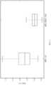
図19~22を参照すると、針の貫通試験が実施され、結果が、貫通力をy軸上およびサンプル識別をx軸上に取る箱ひげ図で表示された。中央値は中央線であり、箱は第一四分位および第三四分位を包含し、点線は最小値および最大値にそれぞれ伸びる。 Referring to FIGS. 19-22, needle penetration testing was performed and the results displayed in boxplots with penetration force on the y-axis and sample identity on the x-axis. The median is the median line, the box encompasses the first and third quartile, and the dotted lines extend to the minimum and maximum values, respectively.
針の貫通試験は、MMA20および硬膜4の壁を通して、外径0.014インチおよび10~15度の攻撃角度を有するステンレス鋼の面取り針(遠位傾斜21度、近位傾斜14度)で実施された。例えば、IV Catheter Radio-opaque、REF4056、MOD11などのJelcoによって製造された1-1/4インチの長さを有する20G針。 Needle penetration testing was performed with a stainless steel chamfered needle (distal beveled 21 degrees, proximal beveled 14 degrees) with an outer diameter of 0.014 inches and an attack angle of 10-15 degrees through the wall of
図19は、針を用いて中頭蓋窩のMMAおよび硬膜を貫通するための切断力を表す。 FIG. 19 represents the cutting force for penetrating the middle cranial fossa MMA and dura with a needle.
図20は、針を用いて前頭および頭頂骨の下にある(すなわち、凸面)MMAおよび硬膜を貫通するための切断力を表す。 FIG. 20 represents the cutting force for penetrating the underlying (ie, convex) MMA and dura mater of the frontal and parietal bones with a needle.
図21は、針を用いて、前頭および頭頂領域(凸面)のMMAおよび硬膜を貫通するための切断力と中頭蓋窩(頭蓋骨基部)のMMAおよび硬膜を貫通するための切断力とを対比して表す。 FIG. 21 shows the cutting force to penetrate the MMA and dura of the frontal and parietal region (convex) and the MMA and dura of the middle cranial fossa (base of the skull) using a needle. Expressed in comparison.
図22は、針を用いて、上矢状静脈洞の前部、中部、および後部三分の一の側壁を貫通するための切断力を表す。 FIG. 22 represents cutting forces for penetrating the anterior, middle, and posterior third sidewalls of the superior sagittal sinus with a needle.
図19~22に示すように、動脈内腔から硬膜下腔に貫通するために必要な切断力は以下の通りである。1)MMA 20/硬膜4全体:0.75N(標準偏差(SD)0.33N);2):MMA 20/非石灰化硬膜4:0.68N(SD 0.24N);3)MMA 20/石灰化硬膜4:1.29N(SD 0.48N)。中頭蓋窩のMMA20/硬膜4は、0.39N(SD 0.12N)の切断力を必要とした。 As shown in Figures 19-22, the cutting force required to penetrate the arterial lumen into the subdural space is: 1)
0.028インチの外径を有する同じ針と外側傾斜シャフト(遠位の傾斜23度、近位傾斜9度)での、MMA20壁および非石灰化硬膜4の貫通は、1.8N~2.2Nの切断力を必要とした。上記と同じ針および外側シャフトおよび0.045インチの外径を有する先細でないカテーテルでの、MMA20壁および非石灰化硬膜4の貫通は、2N~8Nの切断力を必要とした。上記と同じ針および外側シャフトおよび先細のカテーテル(032インチの先細での内径から0.045インチの最終外径)での、MMA20壁および非石灰化硬膜4の貫通は、1.5N~2.5Nの切断力を必要とした。 Penetration of the
10~15度の攻撃角を有するSSSの壁(硬膜4を含む)を通る針の貫通試験(20G 1-1/4インチのJelco IV Catheter Radio-opaque、REF 4056、MOD11の針を用いた)では、以下の切断力が必要であった。1)SSS全体:0.57N(SD 0.25N)、2)静脈洞の前方三分の一:0.53N(SD 0.22N)、静脈洞の中央三分の一:0.56N(SD 0.28N)、3)静脈洞の後方三分の一:0.61N(SD 0.24N)。トロカール(OD 0.083インチ)およびカテーテル(ID 0.088インチ/OD 0.106インチ)上に取り付けられた針(0.042インチ)によって形成される三軸伸縮穿孔システムを使用して、6Nの力が、SSSを通って硬膜下腔内に穿孔するために必要とされた。 Needle penetration test through walls of SSS (including dura 4) with 10-15 degree attack angle (using 20G 1-1/4 inch Jelco IV Catheter Radio-opaque, REF 4056,
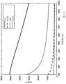
図23を参照すると、十のcSDHを十人の患者の排出手術中に収集し、37℃で、異なるせん断率(例えば、γ=10-2、10-1、1、10、100、および1000s-1)下で粘度を評価するために、レオメーター(reometer)(DHR-1 Hybrid、TA Instruments)で試験をした。図23は、粘度をy軸上にPa-sで、せん断率をx軸上にs-1で取った対数折れ線グラフである。サンプルキーは右上にはめ込まれ、曲線適合は負の勾配を有する破線として示され、水の粘度は、10-3Pa・sの水平の破線として示される(水と標識付けられている)。Referring to FIG. 23, ten cSDH were collected during evacuation surgery of ten patients and subjected to different shear rates (eg, γ=10−2, 10−1, 1, 10, 100, and 1000 s at 37° C.).-1 ) was tested on a rheometer (DHR-1 Hybrid, TA Instruments) to assess the viscosity under. FIG. 23 is a logarithmic line graph with viscosity in Pa-s on the y-axis and shear rate in s-1 on the x-axis. The sample key is inset at the top right, the curve fit is shown as a dashed line with a negative slope, and the viscosity of water is shown as a horizontal dashed line at 10−3 Pa·s (labeled water).
非ニュートンのせん断減粘挙動が観察された。粘度をμ=Kγn-1として推定する(例えば、フィッティング)ためにべき法則を使用し、式中、μは粘度であり、γはせん断率であり、Kおよびnは材料定数で、それぞれ0.113Pa・sおよび0.410に等しい。適合は、サンプル点と相関した破線として示される。Non-Newtonian shear thinning behavior was observed. Use the power law to estimate (eg, fit) the viscosity as μ=Kγn−1 , where μ is the viscosity, γ is the shear rate, K and n are material constants, each equal to 0 .113 Pa·s and equal to 0.410. The fit is shown as a dashed line correlated with the sample points.
図24を参照すると、圧力勾配下で管を通過する非ニュートン流体について、流量Qは
式から、流量はD5.44に比例するので、IDは、MMA20へのカテーテルアクセスを維持しながら、可能な限り大きく選択されなければならない。ID 0.027インチのカテーテルは、18mL/分の吸引流量を生成することができる。我々は、ID 0.027インチを有する150cm長のカテーテルを通して、注射器によって臨床的に関連のある速度でcSDHを吸引できることを見出した。ID 0.027インチのカテーテルは、MMA20内にナビゲートすることができる。From the equation, the flow rate is proportional to D5.44 , so the ID should be chosen as large as possible while maintaining catheter access to the
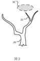
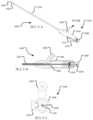
図2は、中硬膜動脈20の出血する膜および/または分岐血管22から形成される硬膜下血腫10の概略図である。側頭下窩で顎動脈を分岐させた後、それは、棘孔を通って硬膜4、外側髄膜層、および頭蓋冠に供給する。cSDHの場合、MMA20はまた、血液を病理学的膜に供給し、収集物を拡大および永続させる。 FIG. 2 is a schematic illustration of a
出血する分岐血管22などの出血する血管を識別するために、撮像手順を実施することができる。例えば、一部の実施形態では、硬膜下血腫10に寄与している出血する血管を特定するために、X線(蛍光透視)および/またはコンピュータ断層撮影(CT)撮像手順を実施することができる。かかる場合、造影剤(例えば、ヨウ素系造影剤)を静脈内に注射し、X線および/またはCT画像を強化するために使用することができる。 An imaging procedure may be performed to identify bleeding vessels, such as bleeding
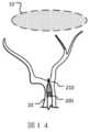
図3は、膜を塞栓し、分岐血管22および分岐が注ぐ膜からの出血を停止または防止するために、塞栓性物質(例えば、液体の塞栓剤、マイクロ粒子など)を注入している例示的なマイクロカテーテル110の概略図である。マイクロカテーテル110は、大腿動脈(鼠径部)もしくは橈骨動脈(手首)または任意の他の適切な血管アクセスポイントなどのアクセスポイントを通って患者の脈管構造内に設置され得る吸引カテーテル100を介して前進する。典型的には、吸引カテーテル100は、ガイドカテーテルの内腔(典型的には5フレンチまたは6フレンチ、例えば5Fまたは6F)を通って顎動脈内に送達され、ガイドカテーテルは患者の末梢動脈の脈管構造、典型的には大腿および橈骨動脈、より一般的ではない場合、上腕動脈および頸動脈に位置する鞘内に導入される。 FIG. 3 is an exemplary infusion of an embolic agent (eg, liquid embolic agent, microparticles, etc.) to embolize the membrane and stop or prevent bleeding from the
本明細書に開示される結果に基づいて、以下の設計仕様は、好ましい実施形態とみなすことができる。吸引カテーテル100は、MMA20をナビゲートするための0.060インチ以下の遠位OD、およびSDH10を排出するための0.020インチ以上の遠位ID、経大腿および経橈骨介入を可能にするための125cm以上の作業長を有する。吸引カテーテル100は、ねじれることなく最小曲線角度70°で前進し、棘孔を通って頭蓋内区画に入ることができる。吸引カテーテル100は、MMA20/硬膜を穿孔するために、ねじれる、卵型になる、またはヘルニアになることなく親内腔または分岐動脈内に入る1Nを超える前方荷重を生成するのに十分なカラム強度を有し、およびMMA20壁および硬膜を通る穿孔部位で崩壊またはねじれることなく、注射器でSDH10を吸引するために虚脱することなく20inHg超の吸引力を生成する。 Based on the results disclosed herein, the following design specifications can be considered the preferred embodiment.
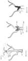
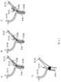
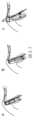
図4は、MMA20の壁に、硬膜下血腫10に向かう方向に、穿孔を穿刺する、例示的なスタイレット130の概略図である。スタイレット130は、MMA20の壁の貫通を支援する傾斜遠位端部分を有し得る。スタイレット130は、シャフト120の内腔を通って前進し、これは次に吸引カテーテル100の内腔を通って前進する。 FIG. 4 is a schematic illustration of an
シャフト120は、ワイヤの上を前進してMMA20中に入る0.014インチマイクロワイヤと適合性がある(例えば、IDが0.014インチより大きい)。シャフト120のIDは、150~250μmのサイズであるPVA粒子を注入するために0.012インチより大きく、硬膜4を捕捉するためにカテーテルの端を避けるためにカテーテルのIDよりも小さい0.006インチ未満の遠位ODを有する。シャフト120は、スタイレットを硬膜下腔に向ける単方向の偏向を含む。
スタイレット130は、シャフト120の端が硬膜4を捕捉するのを避けるために、シャフト120のIDよりも小さい0.003インチ未満の遠位ODを含む。スタイレット130は、シャフト120を通って最小曲線角度70°で前進し、棘孔を通って頭蓋内区画に入る。スタイレット130は、1N未満の切断力の経動脈的穿孔のための遠位端に鋭利な面取り針、および最小曲線角度70°でカテーテルを通る送達に適合する直径を有する閉鎖装置、とを含む。これにより、スタイレット130は、押すか、または取り外すことを介して、棘孔を通って頭蓋内区画に入ることができる。すべてのサブコンポーネントは、放射線不透過性(例えば、従来の蛍光透視法で可視化されるのに十分なX線減衰を提供する)であるか、または少なくとも一つまたは複数の放射線不透過性領域を有する。代替的に、構成要素は、金、白金、白金イリジウム、タンタル、ビスマス、およびタングステン充填ポリマーなどの一つまたは複数の蛍光透視マーカーを含み得る。 The
一部の実施形態では、マーカーは、穿孔要素の後端部に適用され、前端部での相対的な位置を示す。マーカーは、装置の各要素の回転配向または相対奥行きを示すことができる。 In some embodiments, a marker is applied to the trailing end of the piercing element to indicate its relative position at the leading end. The markers can indicate the rotational orientation or relative depth of each element of the device.
一部の実施形態では、スタイレット130およびシャフト120の後端部は、これらの要素の相対的な長さの調整を可能にする組立によって結合される。組立の例は、ノブまたはホイールによって操作されるねじ込みねじを含み得る。この組立は、スタイレット130を遠位シャフト120内に有利に収納し、スタイレット130の傾斜先端が、特に棘孔の角のある部分において前進中に吸引カテーテル100の内面を損傷する、例えば、引っかくおよび/または捕捉するのを防止する。この組立は、スタイレット130の切断傾斜を、奥行き制御された貫通のためにシャフト120の遠位に一定の距離で露出する。 In some embodiments, the
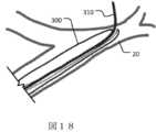
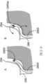
図5は、MMA20の壁穿孔を通って硬膜下血腫10へ向かって前進する例示的なシャフト120の概略図である。シャフト120は、スタイレット130の上を前進し、適切に高い押出し性(例えば、カラム強度)を有する。シャフト120の可撓性の遠位端部分は、シャフト120が硬膜下血腫10に向かって非外傷的に前進できるように、自然な非拘束の湾曲した形状(例えば、J型)を有する。0.040インチのODを有するマイクロカテーテル110を、0.014インチのマイクロワイヤの先端の上を、死体のヒト頭部の硬膜下腔を通って前進させることに基づいて、硬膜下ナビゲーションは実行可能であり、非外傷性などの肉眼で見える脳損傷をもたらさない。硬膜下腔内の前進中、J型またはU型は脳表面に平行である。これにより、望ましくない脳貫通のリスクが低減する。シャフト120の前進が脳表面とSDHとの間にシャフト120を配置する場合、シャフト120は回転してJまたはU形状をSDHに向け、その後前進する。 FIG. 5 is a schematic illustration of an
シャフト120は拘束されていないJまたはU形状を有するが、シャフト120の遠位端部分はスタイレット130の上にあり、スタイレット130の剛性は、シャフト120の遠位端部分をまっすぐにする(例えば、図4で描写する通り)。一部の実施形態では、シャフト120は、コイル状ワイヤで補強されたマイクロカテーテルである。スタイレット130の相対位置をシャフト120の上に変更することによって、シャフト120の剛性および形状が変更される。 Although
図6は、シャフト120の上を、MMA20の壁穿孔を通って、硬膜下血腫10へ向かって前進する例示的な吸引カテーテル100の概略図である。吸引カテーテル100は、ワイヤ補強チューブとすることができる。吸引カテーテル100は、開ポートを有する吸引カテーテル100の遠位端部分が硬膜下血腫10内に配置されるまで前進するであろう。カテーテル100の前進は、硬膜下腔への溶液の注入によって促進され得る。シャフト120およびカテーテル100は、テフロン(登録商標)などのような潤滑物質によって被覆され得る。 FIG. 6 is a schematic illustration of an
図7は、硬膜下血腫10内に位置付けられた吸引カテーテル100の遠位端部分を示す概略図である。ここから、吸引カテーテル100を使用して吸引を適用して、血液および/または他の液体を吸引して、硬膜下血腫10を少なくとも部分的に排出することができる。吸引カテーテル100のワイヤ補強は、硬膜下血腫10を吸引するために真空が適用される間、吸引カテーテル100が虚脱するのを防ぐのに役立ち得る。適用される真空は、低周波数および/または高周波数で、連続的、動的、周期的、および拍動性であり得る。脈動圧は、吸引除去を容易にする血餅の疲労および破砕を誘導する。液体排出は、頭蓋内区画と大気との間の圧力勾配によって自然に発生することがある。真空は、注射器またはポンプのいずれかを使用して適用することができる。 FIG. 7 is a schematic diagram showing the distal end portion of
図8は、MMA20の壁穿孔を閉塞し、MMA20の分岐血管を閉塞するために、止血要素180(例えば、穿刺部位、または別のタイプのプラグ材料/装置に急速な止血をもたらすために使用することができるコラーゲン材料)を送達する吸引カテーテル100の概略図である。その後、図9に描写するように、吸引カテーテル100を抜去して、硬膜下血腫10を排出するための図2~9に記載される手順を完了することができる。 FIG. 8 illustrates a hemostatic element 180 (e.g., puncture site, or another type of plug material/device used to provide rapid hemostasis to occlude wall perforations in
図2~9は、本明細書で血管外アクセスカテーテル(EVAC)とも呼ばれる、装置のプラットフォームを記述する。上述のように、EVAC装置は、少なくとも吸引カテーテル100、およびマイクロカテーテル110ならびにシャフト120によって形成され得る穿孔要素、とを含む。しかしながら、これらの構成要素のうちの二つは、類似の手順ステップを達成するための設計により単一の構成要素に統合されてもよく、またはより多くの構成要素が追加されてもよい。 Figures 2-9 describe the device platform, also referred to herein as an extravascular access catheter (EVAC). As mentioned above, the EVAC device includes at least an
EVAC装置は、血管内区画から硬膜下腔へのアクセスを提供し、通路が開存している間に血液の溢出を防止し、脳穿孔または損傷なしに頭蓋内区画内のナビゲーションを可能にし、硬膜下収集物の排出を可能にし、およびEVAC装置の除去時に通路閉鎖(および必要に応じて動脈閉塞)を確保するプラットフォームである。 The EVAC device provides access from the intravascular compartment to the subdural space, prevents extravasation of blood while the passageway is patent, and allows navigation within the intracranial compartment without brain perforation or injury. , a platform that allows drainage of subdural collections and ensures passageway closure (and arterial occlusion, if necessary) upon removal of the EVAC device.
図25A~25Eを参照すると、EVAC装置2500の一実施形態が示されている。一部の実施形態では、図25Aに示すEVAC装置2500は、本明細書に記載の吸引カテーテル2510のサブコンポーネント(例えば、マイクロカテーテル、シャフト2520、またはスタイレット2530)であり、直接手動で、または少なくとも部分的にハンドルアセンブリ2540によって作動される。ハンドルアセンブリ2540の一実施形態では、吸引カテーテル2510は、ユーザに近位の端部で、SDH10吸引のための真空源に接続されたポート2560を含むハンドルハウジング2550に取り付けられる。 Referring to Figures 25A-25E, one embodiment of an
ハンドルハウジング2550の内部において、および吸引カテーテル2510と同軸で、シャフト2520は、スライダ2570への近位端で組み立てられ、スライダ2570をハンドルハウジング2550上のスロット2572に沿ってスライドさせて押すか引くことによって作動させると、それは、吸引カテーテル2510内で、シャフト2520の対応する同軸並進運動を発生させる。シャフト2520の遠位端は、スライダノブ2570を使用して、吸引カテーテル2510遠位端に対して位置付けられる。スライダ2570は、シャフト2520の位置を吸引カテーテル2510内に維持するために、止めねじ方式(例えば、止めねじを使用して、またはシャフト2520の並進動作を凍結するためにハンドルハウジング内に回転して入る)で、ハンドルハウジング2550に対して回転可能に締められる。一部の実施形態では、シャフト2520は、非外傷性マイクロワイヤを配置する中空内腔を有する傾斜切断先端を有する。 Within
ハンドルハウジング2550の近位端は、スタイレット2530が組み立てられるスタイレットノブ2580を受領する。図25Bは、吸引カテーテル2510、シャフト2520、およびスタイレット2530の入れ子アセンブリを含む、ハンドルアセンブリ2540の構成要素の断面図を示す。スタイレット2530は、スタイレットノブ2580内で近位端にて終了および付着する。スタイレットノブ2580は、スタイレットノブ2580をハンドルハウジング2550の内外に駆動する回転を通してスタイレット2530の相対位置を制御する。 The proximal end of
リングシール2590は、吸引カテーテル2510およびシャフト2520の近位端に配置され、これにより真空漏れおよびシステムへの空気の導入が低減される。一実形態では、吸引カテーテル2500、シャフト2520、およびスタイレット2530のそれぞれは、生理食塩水潤滑およびSDHの希釈などの液体を注入するための液体ポートを有する。代替的な実施形態では、これらのポートはまた、ポート2560などの、SDH吸引を強化するために真空源に接続されてもよい。様々な代替的な実施形態では、個別のマーカーまたはルーラーは、シャフト2520、吸引カテーテル2500、および/またはスタイレット2530の遠位端の相対的位置を示すために、スライダ2570および/またはスタイレットノブ2580上に標識される。別の実施形態では、ナットなどの内ねじを有するスペーサーは、スタイレットノブ2580とスライダ2570との間に組み立てられて、シャフト2520遠位端からのスタイレット2530の最大突出を減少させることができ、ハードストップを提供する。 A
図25Cは、ハンドルハウジング2550およびスライダ2570を通り、ハンドルハウジング2550、スタイレット2530、およびシャフト2520の長手方向軸に垂直な、ハンドルアセンブリ2540の横断断面図である。スライダ2570の回転可能な接続が左に示される。スライダ2570は、スライダ2570がハンドルハウジング2550と接触し、ハンドルハウジング2550に対するシャフト2520の位置を維持するまで回転する。 25C is a cross-sectional view of
EVAC装置2500は、周辺アクセスからMMA内にナビゲートされ、膜の微小血管閉塞のための動脈内塞栓性物質を送達するために使用される。次に、EVAC装置2500を使用して、動脈壁を意図的に穿孔し、硬膜下腔(例えば、脳、硬膜、および頭蓋骨の間)を通って前進し、慢性硬膜下血腫(cSDH)を排出する。アクセス中、止血要素は、血管外通路を閉じる動脈穿孔および/またはMMAの内腔にわたって配置、送達、または注入される。 The
本明細書に記載の装置、システム、および方法は、硬膜下腔からの液体、血餅、および粒子状物質の排出のみを目的としたものではないことが理解されるべきである。代わりに、本明細書に記載の方法およびシステムは、安全なアクセスの取得、および例えば、急性硬膜外血腫、嚢胞液および膿の排出などの、硬膜上腔内での液体や血餅の排出のために適合され得る。これらの場合、システムはまた、排出カテーテルの内側、外側、または両方に配置される、血餅を軟化する要素(例えば、回転要素、振動要素、流体ジェットなど)を含み得る。さらに、本明細書に記載の方法およびシステムは、くも膜下腔、槽、脳組織および脳室を含む、硬膜内区画内の任意の頭蓋内標的へのアクセスを得るために適合され得る。 It should be understood that the devices, systems, and methods described herein are not intended solely for the evacuation of fluids, clots, and particulate matter from the subdural space. Instead, the methods and systems described herein are used to obtain safe access and to remove fluids and clots within the epidural space, such as acute epidural hematoma, cystic fluid and pus drainage. It can be adapted for ejection. In these cases, the system may also include clot softening elements (eg, rotating elements, vibrating elements, fluid jets, etc.) positioned inside, outside, or both of the drainage catheter. Additionally, the methods and systems described herein can be adapted to gain access to any intracranial target within the intradural compartment, including the subarachnoid space, cisternae, brain tissue and ventricles.
本明細書に記載の装置、システム、および方法は、動脈を通じた液体または粒子状物質の排出のみを目的としたものではないことが理解されるべきである。代わりに、本明細書に記載の方法およびシステムは、硬膜下または硬膜上腔への安全なアクセスを取得し、静脈、硬膜静脈洞および任意の他の自然の回廊を通して液体、粒子状物質および血餅を排出するために適合され、使用され得る。 It should be understood that the devices, systems, and methods described herein are not intended solely for the evacuation of fluids or particulate matter through arteries. Instead, the methods and systems described herein obtain safe access to the subdural or epidural space, and pass liquids, particulates, through veins, venous dural sinuses and any other natural corridor. It can be adapted and used to drain material and clots.
本明細書に記載の装置、システム、および方法は、任意の血管外空間への安全かつ安定した経血管的アクセスを取得し、その後、動脈切開または静脈切開部位を閉じるために使用され得ることが理解されるべきである。 The devices, systems, and methods described herein can be used to obtain safe and stable transvascular access to any extravascular space and subsequently close the arteriotomy or phlebotomy site. should be understood.
変形および他の実施形態および/または特徴
一部の実施形態では、シャフト120は、動脈壁の貫通および硬膜下血腫への進入を容易にするために、ジアテルミー、電気焼灼、または任意の他の電気的特徴を有する。また、硬膜下血腫、血腫内の隔壁、または任意の出血源を取り囲む膜を切断および/または凝固させるために、ジアテルミー、レーザー、および電気焼灼を使用することもできる。MMAなどの経血管的通路および血管内腔を閉じるために、ジアテルミー、レーザー、および電気焼灼を使用することもできる。単極または双極焼灼は、別個の構成要素として、または吸引カテーテル100および/またはシャフト120に統合されて使用され得る。一部の実施形態では、シャフト120は単極(シャフトの少なくとも部分、概して先端)として作用することができ、シャフト120およびカテーテル100(少なくともセグメント、概して遠位端)は結合動作中に双極として作用することができる。Variations and Other Embodiments and/or Features In some embodiments, the
一部の実施形態では、シャフト120または吸引カテーテル100は熱アブレーションで結合され得る。 In some embodiments,
ここで図26A~26Fを参照すると、一部の実施形態では、少なくとも一つの貫通要素(スタイレット2630、シャフト2620、および吸引カテーテル2600)は、高周波(RF)アブレーションチップを有する。RFエネルギーを適用して、組織温度を急速に上昇させ、液体を蒸気に変換する(すなわち、気化)ことにより、焦点組織破壊および空隙をもたらす。気化は、血管内腔から硬膜内区画への開窓をもたらし得る。これは、切断端を有する機械的針と比較して、穿孔のための切断力を低減し、カラム強度を低減させることに有益である。結果として生じる組織空隙はまた、経血管的通路に沿ってエッジが捕捉する可能性を低減するであろう。さらに、非外傷性RF針の先端は、シャフトおよび吸引カテーテルを損傷する可能性が低い。 26A-26F, in some embodiments, at least one penetrating element (
一部の実施形態では、RFエネルギーは、周囲の膜を通じてのSDHへの進入、混合年齢SDHおよび慢性SDHに関連する隔壁の穿孔を促進し、排出管状要素(例えば、吸引カテーテル)の開口部の詰まりを解消するために使用される。 In some embodiments, RF energy promotes entry into SDH through surrounding membranes, perforation of the septum associated with mixed-age SDH and chronic SDH, and the opening of drainage tubular elements (e.g., aspiration catheters). Used to clear blockages.
一部の実施形態では、RFアブレーションエネルギーは、同じまたは追加のRF要素によって送達されて、介入の終了時に必要に応じて、貫通部位および動脈閉鎖で組織を凝固させることもできる。一部の実施形態では、RF要素先端は、RF要素の遠位端から近位端まで延在し、ハブ内の電気ジョイントによってRF発生装置に接続された接続ワイヤを有する二つ以上の電極を含む。これらのワイヤは、典型的には、ステンレス鋼、銅、および銀などの導電性金属から作製され、PTFEなどのプラスチック層で絶縁されるか、またはシャフトまたは吸引カテーテルの壁内に埋め込まれることによって絶縁される。電極は絶縁されておらず、ステンレス鋼、銀、金、または白金などの高い放射不透過性を有する導電性および生体適合性金属で作製されるか、または被覆される。一部の実施形態では、一つまたは複数の電極は、単極様式で並列に動作し、同じ接地パッドを共有するために、RF発生装置に個別に接続される。二つの電極を有する別の実施形態では、電極の一方はRF発生装置に接続され、他方の電極は接地に接続され、双極様式で機能する。別の実施形態では、単一または複数(2を超える)の電極は、RF要素に組み立てられ、その単極または双極様式で機能するように構成され得る。双極システムでは、電流は二つの電極の間に優先的に集中する。 In some embodiments, RF ablation energy can also be delivered by the same or additional RF elements to coagulate tissue at the penetration site and arterial closure as needed at the end of the intervention. In some embodiments, the RF element tip has two or more electrodes with connecting wires extending from the distal end to the proximal end of the RF element and connected to the RF generator by electrical joints in the hub. include. These wires are typically made from conductive metals such as stainless steel, copper, and silver and are either insulated with a layer of plastic such as PTFE or embedded within the shaft or wall of the suction catheter. insulated. The electrodes are not insulated and are made of or coated with highly radiopaque, conductive and biocompatible metals such as stainless steel, silver, gold, or platinum. In some embodiments, one or more electrodes are individually connected to the RF generator to operate in parallel in a monopolar fashion and share the same ground pad. In another embodiment having two electrodes, one of the electrodes is connected to the RF generator and the other electrode is connected to ground, functioning in a bipolar fashion. In another embodiment, single or multiple (more than two) electrodes can be assembled to the RF element and configured to function in its monopolar or bipolar fashion. In a bipolar system, current is preferentially concentrated between two electrodes.
一部の実施形態では、双極構成は、吸引カテーテル内の電極および穿孔要素内の一つの電極によって得ることができる。穿孔要素は、吸引カテーテルから出現したときに形状を獲得して、先端を動脈壁および硬膜に向け得る。貫通要素および吸引カテーテルは、電極間の距離と組織への電流の送達とを維持しながら同時に前進することができ、または穿孔要素は吸引カテーテルを固定しながら前進することができ、これは組織破壊の低下および脳の貫通の可能性の減少を伴う電極間の距離の増大をもたらす。 In some embodiments, a bipolar configuration can be obtained with an electrode in the aspiration catheter and one electrode in the piercing element. The piercing element may acquire a shape when it emerges from the aspiration catheter and point the tip toward the artery wall and dura mater. The penetrating element and the aspiration catheter can be advanced simultaneously while maintaining the distance between the electrodes and the delivery of current to the tissue, or the piercing element can be advanced while the aspiration catheter is fixed, which can lead to tissue disruption. resulting in an increase in the distance between the electrodes with a decrease in the sphincter and a decrease in the likelihood of penetrating the brain.
一部の実施形態では、エネルギー送達装置の電極は、弾丸、円錐、切断された円錐、円筒、球、ドーム、リング、半環状、楕円、傾斜、および矢じりの形のうちの一つの形状を有する。形状は、優先的な電流送達および方向的穿孔のために、少なくとも部分的に電気的に絶縁され得る。電極の電気的に露出した領域は、16mm2以下であり、典型的には2mm2~10mm2の範囲内である。In some embodiments, the electrodes of the energy delivery device have a shape of one of bullet, cone, truncated cone, cylinder, sphere, dome, ring, semi-annular, elliptical, oblique, and arrowhead shapes. . The shape can be at least partially electrically insulated for preferential current delivery and directional perforation. The electrically exposed area of the electrodes is 16 mm2 or less, typically in the
一部の実施形態では、RF穿孔要素は、ステンレス鋼、銅、チタン、およびニッケル-チタン合金を含む導電性材料から作製された実質的に管状な部材からなる。管状要素は、RF発生装置に近位に結合され、その上に配置された電気絶縁体を有し、最小限の遠位領域の散逸で非絶縁セグメントまたは電極にエネルギーを送達する。管状要素の遠位端は、開または閉とすることができる。管状要素は、先細であってよく、手持ち式作動装置に結合されてもよく、また本明細書に記載されるように、柔軟性を高めるためにスコア付けされてもよい。一部の実施形態では、二つ以上の管状要素を結合して、RF穿孔要素を形成することができる。 In some embodiments, the RF piercing element consists of a substantially tubular member made from electrically conductive materials including stainless steel, copper, titanium, and nickel-titanium alloys. The tubular element is proximally coupled to the RF generator and has an electrical insulator disposed thereon to deliver energy to the uninsulated segment or electrode with minimal distal area dissipation. The distal end of the tubular element can be open or closed. The tubular element may be tapered, may be coupled to a handheld actuator, and may be scored for flexibility as described herein. In some embodiments, two or more tubular elements can be joined to form an RF piercing element.
図26A~26Fは、RFアブレーション装置およびかかる装置を使用してSDH2610を除去するステップを描写する。図26Aは、MMA2620の壁の近くで、硬膜下血腫2610に向かう方向に位置付けられた例示的なRFスタイレット2630の概略図である。 Figures 26A-26F depict RF ablation devices and steps to remove
高周波エネルギーは、発生装置によって生成され、貫通部材の遠位端に取り付けられた一つ(例えば、単極配置)または複数(例えば、双極配置)の電極(例えば、双極アレイの二つの電極)によって送達される。電極は、貫通部材の遠位端から近位端まで延在する貫通部材の壁内部に埋め込まれ、または壁に取り付けられた導電性ワイヤを介して、電気波発生器に接続される。導電性ワイヤは、最先端を除いて全長に沿って電気的に絶縁されている。電気波発生器は、300~600kHz(例えば、400kHz~600kHz、500kHz~600kHz、300kHz~500kHz、または300kHz~400kHz)、および120~220V(例えば、140V~220V、160V~220V、180V~220V、200kHz~220kHz、120kHz~200kHz、120kHz~180kHz、120kHz~160kHz、または120kHz~140kHz)の範囲の高周波電気波形を生成する。 Radio frequency energy is generated by a generator and delivered by one (eg, monopolar configuration) or multiple (eg, bipolar configuration) electrodes (eg, two electrodes in a bipolar array) attached to the distal end of the penetrating member. delivered. The electrodes are connected to the electric wave generator via conductive wires embedded within or attached to the wall of the penetrating member that extend from the distal end to the proximal end of the penetrating member. The conductive wire is electrically insulated along its entire length except for the extreme ends. The electric wave generator is 300-600 kHz (e.g., 400 kHz-600 kHz, 500 kHz-600 kHz, 300 kHz-500 kHz, or 300 kHz-400 kHz) and 120-220 V (e.g., 140 V-220 V, 160 V-220 V, 180 V-220 V, 200 kHz -220 kHz, 120 kHz-200 kHz, 120 kHz-180 kHz, 120 kHz-160 kHz, or 120 kHz-140 kHz).
一部の実施形態では、貫通部材は、RF能力および非外傷性の鈍いまたは丸い遠位端を有するスタイレット2630によって形成される場合、図26Aに示すとおりである。図26Bでは、スタイレット2630は、RFエネルギー2632を送達しながらMMA20を貫通し、次いでシャフト2620、その後吸引カテーテル2600の同軸前進(図26B)が示される。スタイレット2630は、その後、硬膜下腔を非外傷的に前進するか、またはワイヤによって交換されるように使用され得る。 In some embodiments, the penetrating member is as shown in FIG. 26A when formed by a
一部の実施形態では、図26Cに示す通り、RFスタイレット2630は、シャフト2620または吸引カテーテル2600から出てきた際に、曲線またはピッグテール形状を取得する(図26D)。これは、血管内腔への意図しない後退を防止し、硬膜下腔への装置前進中の脳穿孔を防止するのに有益であり得る。 In some embodiments, as shown in Figure 26C, the
他の実施形態では、シャフト2620は、RF能力を有する。シャフト2620は、RFエネルギー2632を送達しながら、蛍光透視誘導下で経動脈的に穿孔点まで前進し、その後、動脈壁および硬膜を通って硬膜下腔内に押し込まれる。次に、シャフト2620を通して硬膜下腔内にワイヤを押し込み、その後に吸引カテーテル2600を前進させることができる。 In other embodiments,
図26Dは、硬膜下血腫2610内に位置付けられた吸引カテーテル2600の遠位端部分を示す概略図である。ここから、上述のように、吸引カテーテル2600を使用して吸引を適用して、血液および/またはその他の液体を吸引して、硬膜下血腫2610を少なくとも部分的に排出することができる。 26D is a schematic diagram showing the distal end portion of
図26Eは、MMA20壁を通して収納された吸引カテーテル2600および適用されたRFエネルギー2632を示す概略図である。一部の実施形態では、RFエネルギー2632は、電極を介してMMA20壁上の開口部に適用され、熱凝固(例えば、凝塊)を誘導して穿孔を閉鎖する。 FIG. 26E is a schematic diagram showing
図26Fは、MMA20の壁を破壊する適用されたRFエネルギー2632から形成される血餅2640を含むMMA20を示す概略図である。 FIG. 26F is a schematic
一部の実施形態では、貫通システムは、一つまたは複数の開口部I、標的組織の穿孔を確認するために注入ポートを通って造影剤を注入するためにチャネルに流体的に連結された遠位セグメント、高周波穿孔中に熱的に影響された領域を減少させるために周囲組織を冷却するための生理食塩水、または硬膜下腔の潤滑性および幅を増加させるための生理食塩水を含む。 In some embodiments, the penetrating system includes one or more openings I, a distal end fluidly coupled to the channel for injecting a contrast agent through an injection port to confirm perforation of the target tissue. the subdural segment, saline to cool the surrounding tissue to reduce the thermally affected area during radiofrequency perforation, or saline to increase the lubricity and width of the subdural space .
一部の実施形態では、単極電極が使用され、別の接地パッドは、蛍光透視誘導下で、貫通部材の遠位端から標的組織を指すベクトルに沿った方向に、患者頭部の周辺部に取り付けられる。これは、最小のエネルギーを使用し、かつ周囲の組織に最小の熱損傷を生じさせる方向的高周波穿孔を可能にするのに有益である。 In some embodiments, a monopolar electrode is used and another ground pad is applied under fluoroscopic guidance to the periphery of the patient's head in a direction along a vector pointing from the distal end of the penetrating member to the target tissue. can be attached to This is beneficial in enabling directional radiofrequency drilling that uses minimal energy and causes minimal thermal damage to surrounding tissue.
別の実施形態では、RFエネルギー2632は、連続的に、またはパルスで適用され得る。 In another embodiment,
別の実施形態では、一つまたは複数の熱電対は、貫通部材の遠位端の近く(例えば、RFスタイレット2630の近く)に取り付けられ、標的部位のおよび/または標的部位の近くの組織温度を監視する。温度信号は、電気波発生器に送信され、パルスRFエネルギー2632の持続時間および負荷サイクルなどの波形パラメータは、電気波発生器を介して変調される。例えば、電気波発生器は、比例-積分-微分(PID)アルゴリズムおよび/またはカルマンフィルタリングアルゴリズムなどの、一つまたは複数の熱電対からの少なくとも温度信号に基づいて波形パラメータを調節するアルゴリズムを含む。 In another embodiment, one or more thermocouples are mounted near the distal end of the penetrating member (eg, near the RF stylet 2630) to measure tissue temperature at and/or near the target site. to monitor. The temperature signal is sent to an electric wave generator through which waveform parameters such as duration and duty cycle of the
別の実施形態では、貫通部材は、傾斜などの一つまたは複数の鋭利な端部を含み、MMA20の血管および硬膜を穿孔し、RFエネルギー2632を減少させて貫通を行う。代替的な実施形態では、RFスタイレット2630は、非外傷性非切断先端を有する。 In another embodiment, the penetrating member includes one or more sharp edges, such as beveled, to pierce the blood vessels and dura mater of
一部の実施形態では、スタイレット2630、シャフト2620、カテーテル2600、またはそれらの組み合わせであり得るRF要素は、一つまたは複数の電極、温度センサ、および/または圧力センサの組み合わせを含む。一実施形態では、二つの圧力センサが、RF要素の先端と組織との間の接触圧力(例えば、第一の圧力センサ)および/または血液もしくはSDH液体などのRF要素を囲む液体の圧力(例えば、第二の圧力センサ)を感知するために、RF要素の遠位端に配置される。 In some embodiments, the RF element, which can be stylet 2630,
第一の圧力センサは、RF要素の先端に配置され、第二の圧力センサは、第一の圧力センサの近位0.2~2mmに配置される。かかる距離は、穿孔プロセスの異なる段階を識別するように選択される。RF要素が血管穿孔点にナビゲートしている時、第一および第二の圧力センサの両方が名ばかりの血圧を測定する。 A first pressure sensor is placed at the tip of the RF element and a second pressure sensor is placed 0.2-2 mm proximal to the first pressure sensor. Such distances are selected to distinguish different stages of the drilling process. Both the first and second pressure sensors measure nominal blood pressure as the RF element navigates to the vessel puncture point.
RF要素が、良好な壁面配置を有する標的組織を押すように前進する場合、接触圧力は高く、これは第一の圧力センサからの高い数値によって反映される。一方、第二の圧力センサは、組織と接触せず、名ばかりの液体圧力のみを測定する。 When the RF element advances to push against target tissue with good wall placement, the contact pressure is high, which is reflected by the high readings from the first pressure sensor. The second pressure sensor, on the other hand, does not contact the tissue and measures nominal fluid pressure only.
組織穿孔の間、第一の圧力センサと組織との間の接触圧は、高から名ばかりに減少する一方、第二の圧力センサと組織との間の接触圧は、名ばかりから高に増加する。組織が穿孔された後、第一および第二の圧力センサの両方が、硬膜下腔内の名ばかりの液体圧力を測定する。別の実施形態では、複数の圧力センサが円周方向に配置され、平均圧力測定値が、RF要素の先端と組織との間の非垂直接触角によるバイアスを減少させるために使用される。 During tissue penetration, the contact pressure between the first pressure sensor and the tissue nominally decreases from high, while the contact pressure between the second pressure sensor and the tissue increases nominally to high. After the tissue is pierced, both the first and second pressure sensors measure nominal fluid pressure within the subdural space. In another embodiment, multiple pressure sensors are circumferentially arranged and the average pressure measurement is used to reduce the bias due to non-normal contact angles between the tip of the RF element and the tissue.
別の実施形態では、そのかかる圧力測定は、RFエネルギー2632の適用を起動および/または終了するために使用される。典型的な穿孔手順では、装置はまず血管穿孔点に前進し、次いで、RF要素の位置および偏向角度が、圧力測定によって組織に対するRF要素の良好な壁面配置が確認されるまで調整される。RFエネルギー2632が活性化され、RF要素は、組織が穿孔され、圧力測定によって確認されるまで、組織を穿孔し始める。別の実施形態では、そのかかる圧力測定は、進行を知らせるために、手術を行う臨床医に信号(光、音、または他の信号の形態で)を与えるために使用される。 In another embodiment, such pressure measurements are used to initiate and/or terminate application of
別の実施形態では、一つまたは複数の温度センサが、RF要素の遠位端に配置され、RF起動中に温度値を監視し、温度値をRF発生装置に供給して、高温または低温に対応する信号を提供する。RF発生装置は、装置のインピーダンス、電圧、負荷サイクル、パルス幅、および/またはそれらの組み合わせを、比例-積分-微分(PID)アルゴリズムおよび/またはカルマンフィルタリングアルゴリズムなどの制御機能を使用して、調整することによって、安全のためにRFエネルギー2632を終了させるために、温度測定値を受信し、RFエネルギー2632を制御することができる。 In another embodiment, one or more temperature sensors are located at the distal end of the RF element to monitor temperature values during RF activation and supply the temperature values to the RF generator to warm or cool the temperature. Provide corresponding signals. The RF generator adjusts device impedance, voltage, duty cycle, pulse width, and/or combinations thereof using control functions such as proportional-integral-derivative (PID) algorithms and/or Kalman filtering algorithms. By doing so, temperature measurements can be received and
一部の実施形態では、シャフト120は、先端をまっすぐにする一つまたは複数の機構、およびシャフト120の少なくとも一つのセグメントの剛性を増加させる一つまたは複数の機構(内部にマイクロワイヤを引く、またはコイルプルシステムなど)を有し得る。 In some embodiments, the
一部の実施形態では、吸引カテーテル100および/またはシャフトの少なくとも一つのセグメントは、偏向および/または操縦可能である。偏向(例えば、操縦)は、カテーテルの残りの部分とは独立した遠位カテーテルセグメント(例えば、端部)の動きを指す。操縦性は、装置の長さに沿ったトルク伝達によって、遠位カテーテルセグメントを回転させる能力(例えば、カテーテルの残りの部分に関して時計回りおよび/または反時計回りに)を指す。 In some embodiments, at least one segment of the
偏向を引き起こすトルクは、装置先端の近くのプルまたはアンカーリングに接続された一つまたは複数のシャフトによって伝達され得る。遠位カテーテルセグメントは、作動時に一つまたは複数の方向に回転し(例えば、回転する、または平面内で屈曲する)、元の形状(例えば、直線状)に戻る。偏向は、対称、非対称、ループ曲線、または複合物とすることができる。偏向は、一つまたは複数の平面で発生し、平面上および平面外であり得る。 The torque that causes the deflection may be transmitted by one or more shafts connected to a pull or anchor ring near the tip of the device. The distal catheter segment rotates (eg, rotates or bends in a plane) in one or more directions upon actuation and returns to its original shape (eg, straight). Deflections can be symmetrical, asymmetrical, loop curves, or compound. Deflection occurs in one or more planes and can be on-plane and out-of-plane.
図27A~27Kは、偏向可能なカテーテルの使用を描写する概略図である。頭蓋骨271、脳272、硬膜274、およびMMA276は、硬膜274と脳272との間のSDH2710と共に示されている。 Figures 27A-27K are schematic diagrams depicting the use of a deflectable catheter.
例えば、一部の実施形態では、吸引カテーテル2700は、吸引カテーテル2700の壁にスライド可能に位置付けられる一つまたは複数のプルワイヤを含む。ワイヤを引くことによって、吸引カテーテル2700の遠位端セグメントを横方向に偏向させることができる。一部の実施形態では、遠位端セグメントは、カテーテル2700の末端の0.5cm以上(例えば、1cm、1.5cm、または2cm)を含む。吸引カテーテル2700を操縦するための偏向能力の使用に加えて、偏向能力は、MMA276などの血管の内壁に対して吸引カテーテル2700を固定する(例えば、位置を維持する)ために作動させることもできる。 For example, in some embodiments, the
吸引カテーテル2700をMMA276の内壁に固定することで、シャフト2720および/またはスタイレット2730の押出し性を強化し、吸引カテーテル2700をMMA276から押し出す反動(例えば、押す可能性)が減少する。吸引カテーテル2700がMMA276の内壁に固定されている間、吸引カテーテル2700の内腔内でシャフト2720および/またはスタイレット2730を押す能力が増強される。 Securing the
かかる実施形態では、吸引カテーテル2700は、図27Aおよび図27Bが示すように、ワイヤ2705の上を前進したシャフト2720の上を前進し、頭蓋内のMMA276内に入ることができる。マイクロワイヤ2705を取り外し、シャフト2720(図27C)を通して塞栓剤を注入してMMA276を塞栓した後、スタイレット2730は、シャフト2720の遠位端(図27D)に前進する。 In such embodiments, the
スタイレット2730の前進は、棘孔に対して近位のシャフト2720を引っ込めて、その後、シャフト2720およびスタイレット2730を遠位のMMA276内腔に同時に前進させることによって促進することができる。回転可能な吸引カテーテル2700は、蛍光透視法を用いて放射線不透過性の蛍光透視要素を可視化することによって配向される(例えば、回転または偏向によって)。 Advancement of the stylet 2730 can be facilitated by retracting the
硬膜274および硬膜下腔に対するカテーテル27の配向が決定され、プルマイクロワイヤが作動され、結果として吸引カテーテルの遠位端セグメントの偏向が生じる(図27D)。カテーテル2700の配向を変化させ、MMA276内腔内に固定することにより、MMA276内のカテーテル2700の位置が維持される。 The orientation of the catheter 27 relative to the
スタイレット2730およびシャフト2720は、図27Eに示す通り、カテーテル2700を通って前進し(同時にまたは続いて)および硬膜下腔を貫通し、および図27Fに示す通り、硬膜下腔に前進する。スタイレット2730は、非外傷性先端を有するマイクロワイヤ2705と交換することができ、一部の実施形態では、上述のようなJ形状などの形状を含み得る。スタイレット2730は、硬膜下腔内、および硬膜下血腫2710内へ前進する(図27G)。 Stylet 2730 and
シャフト2720は、マイクロワイヤ2705の上を前進する。ワイヤ2705は、シャフト2720および吸引カテーテル2700の前進への安定性および支持を提供するために、遠位領域ではより硬くなく(例えば、可撓的)、近位領域ではより堅くてもよい。次に、吸引カテーテル2700は、動脈壁を通って、シャフト2720およびマイクロワイヤ2705(または交換されない場合はスタイレット2730)の上を、硬膜下腔内に前進し、SDH2710内に前進する(図27H)。次に、マイクロワイヤ2705が除去され(図27I)、吸引によってSDH2710が排出される(図27J)。動脈切開は、止血コイル278(図27K)などの止血要素を用いて閉じられる。
一部の実施形態では、シャフト2720は、傾斜を含む遠位端に切断機能、およびワイヤ2705を配置する内腔を有する。この実施形態では、シャフト2720は、カテーテル2700の遠位端の遠位に前進し、硬膜274を貫通するように押し込まれ、その後に硬膜下腔を通ってマイクロワイヤが同軸前進する。一部の実施形態では、吸引カテーテルはシャフト2720の上をスライドして硬膜下腔内にナビゲートする。他の実施形態では、シャフト2720は、硬膜下腔を通ってマイクロワイヤの上を前進し、その後に吸引カテーテルが同軸前進する。 In some embodiments,
図28A~28Cは、それぞれ作動装置2850aおよび作動装置2850bを含む、二つの作動装置2850(例えば、アンカーに取り付けられたプルワイヤ)を含む吸引カテーテル2800を描写する概略図である。図28A~28Cのプルワイヤは破線で示され、アンカーはカテーテル2800軸を横断する黒い帯として示されている。カテーテル2800は、硬膜284に隣接するMMA286内腔内に前進したと示されている。一部の実施形態では、作動装置2850は、カテーテル2800の内部内腔の周りに円周方向に配置されたリングアンカーに取り付けられたプルワイヤである。一部の実施形態では、作動装置2850は、カテーテル2800の外表面に円周方向に固定される。二つの作動装置2850をカテーテル2800内の二つの位置に含むことは、二つの作動装置2850の間にトルクを生成し、単一の作動装置2850を使用するよりも高い角度の偏向を生成する手段を提供する。 FIGS. 28A-28C are schematic diagrams depicting an
図28Aは、硬膜284に隣接するMMA286の内腔内のカテーテル2800の概略図である。一部の実施形態では、作動装置2850aなどの第一の作動装置は、カテーテル2800に沿って、作動装置2850bなどの第一の作動装置と比べより遠位に固定される第二の作動装置よりもより近位に(例えば、遠位端からより遠く)固定される。第一の作動装置2850aを接続するプルワイヤは、第一の経路に沿ってカテーテル2800の表面に沿ってスライド可能に配置され、第二の作動装置2850bプルワイヤは、第二の経路に沿って表面に沿ってスライド可能に配置される。第一の作動装置2850aが作動すると、それがMMA286内の吸引カテーテル2800を作動装置2850aのリングアンカーの位置で横方向に偏向し、それが図28Bでは棘孔の隣にある。図28Cで示す通り、第二の作動装置2850bのプルワイヤは、例えば、第一の作動装置2850aが偏向された方向とは異なる、第二の方向で、吸引カテーテル2800先端を硬膜284に向かって内側に偏向するように作動する。 FIG. 28A is a schematic illustration of
図29Aおよび29Bは、カテーテル2900遠位端を偏向する単一の作動装置2950(例えば、アンカーに取り付けられたプルワイヤ)を描写する概略図である。図29Aおよび29Bのプルワイヤは破線で示され、アンカーはカテーテル2900軸を横断する黒い帯として示されている。一部の実施形態では、一つまたは複数の作動装置2950は、一つまたは複数の関節点および/または一つまたは複数の方向の偏向につながる吸引カテーテル2900壁に沿って、例えば、直線状、湾曲状、「s」形状、またはらせん状の経路などの経路に従うカテーテル2900に取り付けることができる。この構成は、有利な様式で吸引カテーテル2900を空間的に配置する場合に積極的に支援することができる。 29A and 29B are schematic diagrams depicting a single actuator 2950 (eg, a pull wire attached to an anchor) that deflects the
例えば、作動装置2950は、吸引カテーテル2900を関節接合して、棘孔(頭蓋内区画へのMMA296の入口)を中心とする凹面を有する曲線を形成する。作動装置2950は、吸引カテーテル2900を内側に関節接合し、カテーテル2900出口を硬膜294および硬膜下腔に向ける。例えば、遠位セグメントを内側および横方向に湾曲するために吸引カテーテル2900を関節接合することができるらせん状に整列した作動装置2950は、頭蓋骨基部および硬膜294の解剖学的構造および固定点に従って、硬膜下腔への方向付け可能な貫通のためのカテーテル2900の挿入およびMMA296の横断を受け入れるであろう。 For example, the
一部の実施形態では、吸引カテーテル2900の関節接合は、プルワイヤ、ノッチ、プリセット曲線、形状、および/または当業者によって明らかである任意の他の機構などの、作動装置2950または2850を提供することができる一つまたは複数の作動装置を用いて達成することができる。一部の実施形態では、プルワイヤまたは他の関節接合要素などの作動装置が、シャフト内に存在する。 In some embodiments, articulation of
一部の実施形態では、一つまたは複数の受動的(例えば、関節接続不可能)ワイヤを使用して、吸引カテーテル2900を安定化し、および方向を提供することができる。 In some embodiments, one or more passive (eg, non-articulatable) wires can be used to stabilize and provide direction to the
一部の実施形態では、バルーンへの送気、遠位血管セグメント内に配置され、かつ一つまたは複数の伸縮要素に機械的に接続されるステント、または他の拡張可能要素の配置は、穿孔要素の押出し性を高め、反動を低減することができる。 In some embodiments, insufflation of a balloon, deployment of a stent or other expandable element positioned within the distal vessel segment and mechanically connected to one or more telescoping elements is performed by perforation. The extrudability of the element can be increased and the recoil can be reduced.
一部の実施形態では、シャフト120および/またはスタイレット130の押出し性の強化は、吸引カテーテル100の反動を減少させ、分岐する付属物を有する送達鞘をワイヤの上を動脈分岐内に前進させることによって方向性を達成できる。図30Aから30Eは、MMA306の分岐部などの、動脈分岐部で外部表面に付着した第二のカテーテル3002を含む吸引カテーテル3000を描写する概略図である。第二のカテーテル3002は、第一のカテーテル3000よりも小さな内側内腔を有する。 In some embodiments, enhanced pushability of
MMA306は、典型的には硬膜の硬膜外側に位置し、典型的には硬膜に平行な平面に分岐を有する。第二のカテーテル3002を含むカテーテル3000は、MMA306分岐を保持し、カテーテル3000の位置を安定化する付属物を含むことができ、MMA306壁および硬膜を垂直に中央化された軌道で穿孔するための3次元配向を提供する。 The
図30Bは、J形状の遠位端を有するワイヤとして付属物3010を描写するが、付属物3010は、カテーテル3000および第二のカテーテル3002に停止張力を提供するのに十分な、ハイポチューブ、カテーテル、ステント、バルーン、または他の展開可能な要素であってもよい。付属物3010がワイヤである実施形態では、メインカテーテル3000の内腔内またはメインカテーテル3000の壁に配置または付着された第二のカテーテル3002の内腔内を移動することができる。付属物3010は、独立した構成要素として、または送達カテーテル3002からの展開可能な付属品として配置される。 Although FIG. 30B depicts
カテーテル3000は、穿孔要素3012へのアクセスを可能にし、硬膜下腔に向かって配向可能な軸外開口部を提供する、予め作られた開口部3004を有する。一部の実施形態では、穿孔要素3012は、カテーテル3000を通って前進し、硬膜下腔内に貫通する針である(図30C)。穿孔要素3012の形状は、永久的であってもよく、または可鍛性材料(例えば、ニチノール)からなってもよい。
形状はまた、穿孔要素3012内の形取られた内側要素によっても提供され得る。穿孔要素3012が吸引カテーテル3000または送達鞘を超えて前進する距離は、穿孔距離(dp)と呼ばれる。この距離、dpは、本明細書に記載のハンドルによって、固定され、一時的に固定され、または調整可能であり得る。Shape can also be provided by a profiled inner element within the piercing
一部の実施形態では、穿孔要素3012は中空であり、造影剤は、穿孔要素3012内腔を通って硬膜下腔内に注入され得る。図30Cは、造影剤3015を硬膜下腔内に注入する穿孔要素3012を描写する。次いで、穿孔要素3012の先端位置は、硬膜内の針先端位置を確認するために、造影剤と比較して視覚化することができる。別の方法として、他の液体を、穿孔要素3012内腔を通して注入することができる。例えば、硬膜下腔のサイズおよび潤滑性を増加させるための、水などの液体の注入。 In some embodiments, the piercing
図30Dは、穿孔要素3012を通って、例えば、SDHの中などの、硬膜下腔の中へと同軸に前進したマイクロワイヤ3014を描写する。一部の実施形態では、第三の吸引カテーテル3016は、硬膜を通って、マイクロワイヤ3014の上を、穿孔要素3012の上を、図30Eが示すように、SDHの硬膜下位置などに前進することができる。経動脈的通路の作製後に硬膜下腔へのアクセスを失うリスクは、ワイヤを硬膜下腔内に前進させることによって減少する。 FIG. 30D depicts a
一部の実施形態では、吸引カテーテルの遠位端セグメントは傾斜先端を含み、例えば、吸引カテーテルへの開口部は楕円形の開口部を含み、先端平面は吸引カテーテルの横平面に対してある角度であり得る。一部の実施形態では、傾斜先端は、配向のための蛍光透視要素を含む。 In some embodiments, the distal end segment of the aspiration catheter includes a beveled tip, e.g., the opening to the aspiration catheter includes an elliptical opening and the tip plane is at an angle to the lateral plane of the aspiration catheter. can be In some embodiments, the beveled tip includes a fluoroscopic element for orientation.
吸引カテーテルの傾斜先端は、MMA壁の硬膜下腔への貫通を容易にする。吸引カテーテルの貫通能力は、切断端と組み合わせた場合に増加する。傾斜先端は、カテーテル内腔と貫通面との間の並置を改善する。傾斜先端は、貫通方向性を改善し、SDHの排出を容易にする。 The beveled tip of the aspiration catheter facilitates penetration of the MMA wall into the subdural space. The penetration capability of the aspiration catheter is increased when combined with a cut tip. The beveled tip improves apposition between the catheter lumen and the penetrating surface. The beveled tip improves penetration directionality and facilitates SDH evacuation.
一例として、吸引カテーテルは、MMA内に位置付けられ、傾斜先端がMMA壁に面するまで、蛍光透視観察(例えば、蛍光透視法)下で回転される。貫通は、スタイレットおよび/またはシャフトを硬膜下腔内に前進させること、吸引カテーテルでの貫通、または代替的に、予め成形された湾曲した針での貫通と、その後の硬膜下腔内へのワイヤの前進を含むがこれに限定されない、本明細書に開示される任意の実施形態によって達成される。 As an example, an aspiration catheter is positioned within the MMA and rotated under fluoroscopic observation (eg, fluoroscopy) until the beveled tip faces the MMA wall. Penetration may involve advancing a stylet and/or shaft into the subdural space, penetration with an aspiration catheter, or alternatively, penetration with a pre-shaped curved needle followed by penetration into the subdural space. Accomplished by any of the embodiments disclosed herein including, but not limited to, advancing a wire to the .
一部の実施形態では、吸引カテーテルは、動脈壁に対して傾斜先端を位置付け、先端を硬膜下腔に向けて配向する作動装置(例えば、プルワイヤ)を有し、これにより、反動を最小化するためにより強いカラム強度を提供すると同時に、方向的貫通が促進される。一部の実施形態では、シャフトおよびスタイレットの貫通の深さは、ハンドルで維持および調整することができる。典型的な貫通深度は、1mm~10mmの範囲(例えば、2mm~10mm、4mm~10mm、60mm~10mm、8mm~10mm、1mm~8mm、1mm~6mm、1mm~4mm、または1mm~2mm)を含む。 In some embodiments, the aspiration catheter has an actuator (e.g., pull wire) that positions the beveled tip against the arterial wall and orients the tip toward the subdural space, thereby minimizing recoil. directional penetration is facilitated while providing greater column strength for In some embodiments, the depth of penetration of the shaft and stylet can be maintained and adjusted with a handle. Typical penetration depths include a range of 1 mm to 10 mm (eg, 2 mm to 10 mm, 4 mm to 10 mm, 60 mm to 10 mm, 8 mm to 10 mm, 1 mm to 8 mm, 1 mm to 6 mm, 1 mm to 4 mm, or 1 mm to 2 mm). .
一部の例では、CTスキャン画像および/または脳MRI画像などの、介入前または介入中に取得された画像に基づいて、貫通深度が調節可能である。スタイレットおよび/またはシャフトは、硬膜下腔内に最終位置に前進し、ハンドルはシャフト位置をロックするように作動される。スタイレットを除去し、硬膜下腔に造影剤を注入する。領域は、本明細書に記載の方法を使用して撮像され、シャフト遠位端の硬膜下位置を確認する。ワイヤは、シャフト内に同軸で硬膜下腔内に前進する。 In some examples, penetration depth is adjustable based on images obtained before or during the intervention, such as CT scan images and/or brain MRI images. The stylet and/or shaft is advanced into the subdural space to its final position and the handle is actuated to lock the shaft position. Remove the stylet and inject contrast into the subdural space. The area is imaged using the methods described herein to confirm the subdural location of the shaft distal end. The wire is advanced coaxially within the shaft and into the subdural space.
一部の実施形態では、穿孔は、最初にMMA壁および硬膜を内側に貫通し、(例えば、表面に沿って)脳から離れるように横方向に湾曲して、硬膜の硬膜表面に面した傾斜を方向付ける(例えば、「S」形状の)穿孔要素(例えば、針)を用いて生成することができる。穿孔要素の遠位セグメントの湾曲は、MMA内腔に平行な近位セグメント、MMA壁および硬膜を通って斜角で移行する中間セグメント、および硬膜ならびに脳に平行な硬膜下腔内の遠位セグメントをもたらす。この実施形態は、望ましくない脳穿孔のリスクを低減し、脳穿孔の場合には、ワイヤ前進が、硬膜下腔に再入するための軌道に従うことを保証する。 In some embodiments, the perforation first penetrates medially through the MMA wall and dura mater and curves laterally away from the brain (e.g., along the surface) to the dural surface of the dura mater. It can be produced with a piercing element (eg, needle) that orients a facing slope (eg, "S" shaped). The curvature of the distal segment of the piercing element is the proximal segment parallel to the MMA lumen, the middle segment transitioning at an oblique angle through the MMA wall and dura, and the dura and in the subdural space parallel to the brain. Bring the distal segment. This embodiment reduces the risk of unwanted brain perforations and, in the event of a brain perforation, ensures that wire advancement follows a trajectory for re-entry into the subdural space.
一部の実施形態では、作動装置は、吸引カテーテルと関節接合して、傾斜の頂点に向かって偏向させ、その後に針およびシャフトを含む前述した要素のいずれかで穿孔する。 In some embodiments, the actuator articulates with the aspiration catheter to deflect it toward the apex of the tilt, followed by piercing with any of the elements previously described, including needles and shafts.
一部の実施形態では、穿孔要素はスタイレットまたは吸引カテーテルであり得る。一部の実施形態では、穿孔がSDH内に向けられる場合、針を真空源に接続してSDHを排出する、または穿孔要素を収納してSDHとカテーテル内腔との間の通路をもたらすことができる。一部の実施形態では、伸縮要素(例えば、吸引カテーテル、スタイレット、鞘、および/またはマイクロカテーテル)は、要素の剛性を高め、望ましくない回転を最小にし、平面に沿った配向を維持するために、一つまたは複数の構造要素(例えば、レール)を含む。 In some embodiments, the piercing element can be a stylet or an aspiration catheter. In some embodiments, if the perforation is directed into the SDH, the needle can be connected to a vacuum source to drain the SDH, or the perforation element can be housed to provide a passageway between the SDH and the catheter lumen. can. In some embodiments, telescoping elements (e.g., aspiration catheters, stylets, sheaths, and/or microcatheters) are used to increase element stiffness, minimize unwanted rotation, and maintain planar orientation. includes one or more structural elements (eg, rails).
一部の実施形態では、装置は、断層撮影構成要素などの画像構成要素を含む。例えば、装置は、光干渉断層計(OCT)または血管内超音波(IVUS)断層撮影構成要素を含み得る。IVUSを使用する実施形態では、生物学的構成要素に対する以下のエコー輝度の外観が配向を提供する。硬膜および硬膜の付属品は、高エコーである。髄液は低エコーである。脳表層軟膜は、低エコー皮質灰白質の上に重なった明確に定義された高エコー層であり、高エコー白質の上に重なっている。くも膜下腔には、超音波のドップラーモードで多数の血管が含まれる。硬膜下収集物には、ドップラー上の血管が稀であるか、または全く含まれず、硬膜下収集物は、高エコー膜を有してもよく、高エコー、低エコー、またはそれらの組み合わせであってもよい。 In some embodiments, the device includes an imaging component, such as a tomography component. For example, the device may include an optical coherence tomography (OCT) or intravascular ultrasound (IVUS) tomography component. In embodiments using IVUS, the following echogenic appearance of the biological component provides orientation. The dura and dural appendages are hyperechoic. Cerebrospinal fluid is hypoechoic. The superficial pia mater is a well-defined hyperechoic layer overlying the hypoechoic cortical gray matter and overlying the hyperechoic white matter. The subarachnoid space contains numerous blood vessels in the Doppler mode of ultrasound. Subdural collections contain rare or no blood vessels on Doppler, subdural collections may have hyperechoic membranes, hyperechoic, hypoechoic, or a combination thereof. may be
図31A~31Dは、MMA316内に配置された画像構成要素を含む装置の概略図である。図31Aは、マイクロワイヤ3110およびMMA316内の第二の付属マイクロワイヤ3111によって固定された送達鞘3100を描写する。穿孔要素3112は、MMA316壁を貫通すると示されており、任意に、マイクロワイヤ3110の上を遠位MMA内に前進する、一つまたは複数の内腔を有する送達鞘を含み得る。 31A-31D are schematic diagrams of an apparatus including image components located within
送達鞘3100は、遠位端の開口部を貫通点に向けるように回転される。典型的には、送達鞘3100は、近位により高い内径および外径を有し、遠位に先細る(例えば、より低い内径および外径)。これにより、棘孔および頭蓋内のMMA316に入るのを助ける送達鞘3100の柔軟性が増加する。 The
開口部は、送達鞘3100の遠位端に、または遠位端に対して近位(例えば、5cm以内)の側壁(例えば、開口部3004)内にあってもよい。硬膜の外表面におけるMMA316の分岐を利用して、送達鞘3100は、優性分岐内(例えば、図31Aの右の分岐)に前進し、および付属マイクロワイヤ3111は、MMA316分岐の第二の分岐内(例えば、図31Aの左の分岐)に前進する。これにより、送達鞘3100が空間内に配向され、分岐部の平面に垂直で(例えば、脳に向かって)内側の穿孔点に向かって開口部が配置される。T The opening may be at the distal end of
送達鞘3100の配向は、放射線不透過性マーカーおよび/または蛍光透視法に従い、装置を回転させることにより、誘導することができる。代替的に、画像構成要素3160(例えば、OCTまたはIVUS構成要素)を使用して、MMA316分岐内腔を撮像し、装置を回転させて、送達鞘3100およびマイクロワイヤ3110を、MMA316内で検出された生物学的マーカーなどの対応する角マーカーで配向させることができる。 Orientation of the
一つまたは複数の貫通要素(穿孔要素3112、スタイレット、シャフト、または吸引カテーテル)が、開口部およびMMA316壁および穿孔された硬膜に向かって前進する。穿孔要素3112は、開口部からの退出時に湾曲するメモリ材料(例えば、ニチノール)で作製することができ、または硬膜への1度超の(例えば、2度超、5度超、または10度超の)攻撃角度を提供するために、開口部は角度の付いた表面に結合されてもよい。穿孔要素3112は、メモリ材料(例えば、ニチノール)から予め成形され、硬膜下腔内に貫通し、マイクロワイヤのSDHへの同軸前進を可能にするように前進し得る。 One or more penetrating elements (piercing
吸引カテーテルは、硬膜を通って穿孔要素3112の上を進み、その後、硬膜下腔を通って、SDHの位置へワイヤの上を進むことができる。穿孔要素3112は、代わりに、血管内空間からSDHへワイヤの上を前進する吸引カテーテルと交換され得る。一部の実施形態では、装置は、SDHの上で硬膜を穿孔する。これらの場合、穿孔要素3112の前進、およびMMA316壁および硬膜の穿刺の後、穿孔要素3112は、SDHの排出を可能にする。 The aspiration catheter can be advanced through the dura over the piercing
一部の実施形態では、穿孔要素3112は、硬膜を通る貫通のためにスタイレットによって補強される。貫通後、スタイレットは除去されてもよく、SDHを排出するために、穿孔要素3112に内腔を提供する。一部の実施形態では、穿孔要素3112でのSDHへの貫通後、ある長さの交換ワイヤを(硬膜下腔内に穿孔要素3112を通って前進させることができ、装置が除去され、およびワイヤの上で吸引カテーテルと交換され得る。交換ワイヤの長さは、250cm~300cmの範囲である。吸引カテーテルは、動脈切開部位を通って硬膜下腔内にワイヤの上を前進し、SHDにアクセスする。ワイヤが取り除かれ、SDHが排出される。 In some embodiments, the piercing
ここで図31Dを参照すると、吸引カテーテルのサイズを最大化する実施形態を示す。吸引カテーテルは、送達鞘3100の内腔を通して送達される。送達鞘3100は、MMA316分岐内に前進し、MMA316の各分岐におけるワイヤの使用によって配向される。 Referring now to FIG. 31D, there is shown an embodiment that maximizes the size of the aspiration catheter. A suction catheter is delivered through the lumen of
送達鞘3100は、遠位端に開口部を有し、これにより、MMA316壁および硬膜に向かっての穿孔要素の前進が可能となる。一部の実施形態では、穿孔要素の方向は、湾曲した配向を有する予め成形された穿孔要素3112を使用することによって提供することができ、MMA316壁を内側および垂直に穿孔するために蛍光透視法を用いて配向される。 The
配向はまた、送達鞘3100の内面または外面、および/または穿孔要素3112に接続されたレールシステムによっても提供され得る。代替的な実施形態では、穿孔要素3112は、送達鞘3100のID内に固定された偏向面に向かって前進し、その結果、開口部および穿孔点に向かって穿孔要素3112が前進する。 Orientation can also be provided by a rail system connected to the inner or outer surface of
一部の実施形態では、本明細書に記載の穿孔要素は、混合年齢SDHおよび慢性SDHに関連する膜および隔壁を通して穿孔するために使用される。 In some embodiments, the piercing elements described herein are used to pierce through membranes and septa associated with mixed-age SDH and chronic SDH.
一部の実施形態では、穿孔要素3112は、造影剤または生理食塩水を含む液体の注入を可能にする遠位端でまたはその近くで、一つまたは複数の開口部と流体接続される。 In some embodiments, the piercing
一部の実施形態では、硬膜下腔内の穿孔プロセスおよび進入は、例えば、電位差滴定圧力センサ、誘導式圧力センサ、容量式圧力センサ、歪みゲージ圧力センサ、光ファイバー圧力センサ、可変リラクタンス圧力センサ、微小電気機械システム圧力、および圧電圧力センサなどの圧力センサを含む、一つまたは複数のセンサを装置内に含むことによって監視される。 In some embodiments, the perforation process and entry into the subdural space is controlled by, for example, potentiometric pressure sensors, inductive pressure sensors, capacitive pressure sensors, strain gauge pressure sensors, fiber optic pressure sensors, variable reluctance pressure sensors, Monitoring is achieved by including one or more sensors within the device, including micro-electromechanical system pressure and pressure sensors such as piezoelectric pressure sensors.
圧電圧力センサは、圧力信号を捕捉するために、遠位端に近接する穿孔要素3112のOD内に配置された圧電フィルムを含み、信号は、MMA316壁を通る貫通に関連する圧力ピークを含み、硬膜下腔にアクセスする際の圧力低下によるものである。圧力センサはまた、血管内腔から頭蓋内区画内への貫通時に圧力波形(例えば、動脈、頭蓋内、または静脈穿孔波形)を感知することができる。 The piezoelectric pressure sensor includes a piezoelectric film positioned within the OD of the piercing
一部の実施形態では、穿孔プロセスおよび硬膜下腔への進入は、組織の分光値を測定することによって監視される。 In some embodiments, the perforation process and entry into the subdural space is monitored by measuring tissue spectroscopic values.
一部の実施形態では、穿孔手順および硬膜下腔への進入は、組織および液体のインピーダンス値および/または誘電率値を測定することによって監視される。図39は、y軸上の誘電率値をx軸上の電気信号(例えば、RFエネルギー)のkHzの周波数と比較した折れ線グラフである。図39は、図39の線で表される四つの組織(例えば、血管壁、硬膜、または脳表面)または液体(例えば、血液)を含む。個々の線は、右上のキーインセットに従って、適用されたエネルギー周波数に関する例示的な組織または液体の誘電率を表す。血液(実線)は、描写された周波数にわたって最も高い誘電率を有し、脳表面(点線)は、血液よりも低い誘電率を有し、血管壁(破線)は、脳表面よりも低い誘電率を有し、そして硬膜(一点鎖線)は、最大約720kHzまでの最小の誘電率を有し、血管壁は、約720kHzを超えて最小の誘電率を有する。 In some embodiments, the drilling procedure and entry into the subdural space are monitored by measuring tissue and fluid impedance and/or dielectric constant values. FIG. 39 is a line graph comparing permittivity values on the y-axis to frequency in kHz of the electrical signal (eg, RF energy) on the x-axis. FIG. 39 includes four tissues (eg, vessel wall, dura, or brain surface) or fluids (eg, blood) represented by lines in FIG. Each line represents the dielectric constant of an exemplary tissue or liquid with respect to the applied energy frequency, according to the top right key inset. Blood (solid line) has the highest dielectric constant over the depicted frequencies, the brain surface (dotted line) has a lower dielectric constant than blood, and the vessel wall (dashed line) has a lower dielectric constant than the brain surface. and the dura mater (dashed-dotted line) has the lowest dielectric constant up to about 720 kHz, and the vessel wall has the lowest dielectric constant above about 720 kHz.
誘電率とは、組織の集中的(例えば、物体または組織の体積または質量から独立している)電気的特性である。より高い誘電率を有する組織は、交互電流を伝送するとき、または本明細書に記載する本発明では、RF電流を伝送するとき、インピーダンスがより低い。RF周波数範囲(例えば、100~1000kHzの範囲)では、血液は、脳表面と比較してより高い誘電率を有し、その後、血管壁および硬膜が続く。 Permittivity is a convergent electrical property of tissue (eg, independent of the volume or mass of the object or tissue). Tissues with a higher dielectric constant have a lower impedance when carrying alternating currents or, in the invention described herein, when carrying RF currents. In the RF frequency range (eg, 100-1000 kHz range), blood has a higher dielectric constant compared to the brain surface, followed by vessel walls and dura mater.
典型的な動作RFエネルギー周波数範囲(例えば、300~600kHz)では、血液の誘電率は、脳表面の誘電率よりも4倍高く、硬膜および血管壁の誘電率よりも10倍超高い。誘電率におけるかかる大きな差異は、RF要素の位置を検出するために使用され得る。RF貫通中、RF要素は、硬膜および血管壁からの低誘電率(または高インピーダンス)を感知している。硬膜および血管壁が穿孔されると、RF要素が硬膜下腔に入り、脳またはSDHに接触する際に、誘電率の増加(またはインピーダンスの減少)が測定される。かかるインピーダンス信号は、RF発生装置に供給され、RF電力を自動的に減少または遮断し、および/または音、光、振動、もしくはそれらの組み合わせで手術臨床医に通知する。硬膜内介入が完了した後、RF要素を含む機器は血管内腔に引き戻され、再び血液に囲まれる。これは、誘電率の増加(またはインピーダンスの減少)をもたらす。かかる誘電率および/またはインピーダンス信号は、RF発生装置に供給されて、RF電力を凝固モードに修正(例えば、上昇、低下、開始、または終了)し、および/または音もしくは光の様式で、もしくはそれらの組み合わせで手術臨床医に通知を提供する。 In a typical RF energy frequency range of operation (eg, 300-600 kHz), the dielectric constant of blood is four times higher than that of the brain surface and more than ten times higher than that of the dura mater and blood vessel walls. Such a large difference in permittivity can be used to detect the position of the RF element. During RF penetration, the RF element is sensing a low dielectric constant (or high impedance) from the dura mater and vessel wall. Once the dura and vessel wall are perforated, the increase in dielectric constant (or decrease in impedance) is measured as the RF element enters the subdural space and contacts the brain or SDH. Such an impedance signal is supplied to the RF generator to automatically reduce or block RF power and/or notify the operating clinician with sound, light, vibration, or a combination thereof. After the intradural intervention is completed, the device containing the RF element is pulled back into the vessel lumen and surrounded by blood again. This results in an increase in permittivity (or decrease in impedance). Such permittivity and/or impedance signals are supplied to the RF generator to modify (e.g., increase, decrease, initiate, or terminate) the RF power to the coagulation mode and/or in a sound or light manner, or Their combination provides notification to the operating clinician.
一部の実施形態では、穿孔プロセスおよび硬膜下腔への進入は、MMA316壁を通る貫通に関連する推力を測定するために、穿孔要素の近位端に力センサを含むことによって監視される。 In some embodiments, the piercing process and entry into the subdural space is monitored by including a force sensor at the proximal end of the piercing element to measure the thrust associated with penetration through the
一部の実施形態では、穿孔プロセスの後に、患者の外にあってもよい圧力変換器に流体的に連結されたチャネルによって、穿孔要素の先端の圧力を測定する。 In some embodiments, the pressure at the tip of the piercing element is measured after the piercing process by a channel fluidly coupled to a pressure transducer that may be outside the patient.
一部の実施形態では、穿孔プロセスに続いて、貫通要素の前方端に、またはそこから20mm以内に配置され、患者の外部(例えば、外部)に存することができるEEGレコーダに電気的に結合された電極(例えば、EEG測定装置)を用いて、脳波(EEG)活性を記録する。一部の実施形態では、EEG測定装置は、RFスタイレット2630などのRFエネルギー送達装置として機能し得る。この実施形態では、スプリッターとして動作するEEG界面装置は、RF発生装置およびEEGレコーダへの装置の同時接続を可能にする。この実施形態は、RFエネルギー2632送達と同時に連続的なEEG記録を促進する。 In some embodiments, following the drilling process, an EEG recorder is placed at or within 20 mm from the anterior end of the penetrating element and is electrically coupled to an EEG recorder that can reside outside (e.g., external to) the patient. Electroencephalographic (EEG) activity is recorded using electrodes (eg, an EEG measuring device). In some embodiments, an EEG measurement device may function as an RF energy delivery device, such as
これらの特徴を達成するためのスタイレット、シャフト、またはカテーテルの構成は、ハイポチューブ、単一のソリッドロッド、複数の道、束、チューブ(一つまたは複数の内腔を有する)、シャフトストランド、ケーブル(並んで走る二つ以上のワイヤ、接合、ねじれたまたは編組まれた)、コイル、編組、またはそれらの組み合わせからなる群から選択される一つの長手方向要素を含む。 Configurations of stylets, shafts, or catheters to achieve these features include hypotubes, single solid rods, multiple tracts, bundles, tubes (having one or more lumens), shaft strands, A longitudinal element selected from the group consisting of cables (two or more wires running side by side, spliced, twisted or braided), coils, braids, or combinations thereof.
一部の実施形態では、装置のサブコンポーネントは、金属または金属合金(ステンレス鋼、ニチノール、銀、チタン、銅、コバルトクロム、ニッケルクロム、白金イリジウム、およびその他を含むがこれらに限定されない)、ポリマー(ナイロンまたは他のポリアミド、フルオロポリマー、ポリオレフィン、ポリテトラフルオロエチレン、高密度ポリエチエン、ポリウレタン、およびポリイミドを含むが、これらに限定されない)、セラミック、生体吸収性または分解性の構成要素または組合せ、から作製される。 In some embodiments, the subcomponents of the device are metals or metal alloys (including but not limited to stainless steel, nitinol, silver, titanium, copper, cobalt chromium, nickel chromium, platinum iridium, and others), polymers (including but not limited to nylon or other polyamides, fluoropolymers, polyolefins, polytetrafluoroethylene, high density polyethylene, polyurethanes, and polyimides), ceramic, bioabsorbable or degradable components or combinations of produced.
装置の構築は、内側ライナーおよび外側ジャケットを含んでもよく、製造技術は当業者に知られている。これらの要素は、装置への構造支持を強化し、構成要素間の滑らかな伸縮を促進し、穴を封止することによって真空漏れを防止し、および排出される血腫の流れを強化し、ならびに血餅およびフィブリンが吸引カテーテルを詰まらせる可能性を低減するために必要な場合がある。 The construction of the device may include an inner liner and an outer jacket, manufacturing techniques known to those skilled in the art. These elements provide additional structural support to the device, promote smooth expansion and contraction between components, prevent vacuum leaks by sealing holes, and enhance flow of drained hematoma, and It may be necessary to reduce the chance of clots and fibrin clogging the aspiration catheter.
本明細書の装置の要素が、頭蓋内区画内にナビゲートするのに非常に柔軟であり続け、穿孔して硬膜下腔内に進むのに十分なカラム強度を有することが有益である。一部の実施形態では、装置の要素は、MMAへの/内のナビゲーションをするための典型的な値である約0.001lbf・in2を有する0.0002lbfin2~0.005lbfin2の範囲の先端曲げ剛性を有する。一部の実施形態では、装置の要素は、SSSへの/内のナビゲーションをするための典型的な値である約0.028lbf・in2を有する0.006lbfin2~0.15lbfin2の範囲の曲げ剛性を有する。この目的のために、要素は、様々な剛性のセクションを有する。これは、異なる要素構造構成、材料、材料の割り当て、厚さ、材料の量、異なるデュロメーターを有する材料、および/または選択的補強を用いるおよび組み合わせることによって達成される。Advantageously, the elements of the devices herein remain very flexible to navigate within the intracranial compartment and have sufficient column strength to penetrate and advance into the subdural space. In some embodiments, the device element has a range of 0.0002 lbfin2 to 0.005 lbfin2 with about 0.001 lbf·in2 being a typical value for navigating to/within MMA. Has tip bending rigidity. In some embodiments, the device element has a range of 0.006 lbfin2 to 0.15 lbfin2 with about 0.028 lbf in2 being a typical value for navigating to/within the SSS. It has bending stiffness. For this purpose the element has sections of varying stiffness. This is achieved by using and combining different component construction configurations, materials, material allocations, thicknesses, amounts of material, materials with different durometers, and/or selective reinforcement.
一部の実施形態では、サブコンポーネントのいずれかは、例えば、棘孔の曲線を横断するために、要素の柔軟性を増加させるための複数のスコアリングを含み得る。複数のスコアリングは、らせんスコアリングパターン(連続的または中断的)、放射状スコアリングパターン、カスタムメードのスコアリングパターン、放射状リングパターン、長手方向スコアリング、傾斜スコアリング、ウィンドウ、タブ、または穴を含むが、これに限定されるものではない形状またはパターンを取ることができる。スコアリングは、レーザースコアリングおよびエッチングを含む任意の適切なスコアリング方法を使用して、要素内に生成され得る。スコアリングは、サブコンポーネントのうちの少なくとも一部分(例えば、セグメント)にあってもよく、一部の実施形態では、一側面上に優先的に存在する。 In some embodiments, any of the subcomponents may include multiple scoring to increase the flexibility of the element, for example, to traverse the curve of the spinous foramen. Multiple scoring includes helical scoring patterns (continuous or interrupted), radial scoring patterns, custom-made scoring patterns, radial ring patterns, longitudinal scoring, angled scoring, windows, tabs, or holes. It can take on any shape or pattern, including but not limited to. Scoring can be produced in the element using any suitable scoring method, including laser scoring and etching. Scoring may be on at least a portion (eg, segment) of the sub-components, and in some embodiments is preferentially on one side.
一部の実施形態では、サブコンポーネントのいずれかは、その長さに沿って、連続的、遠位方向に先細り、近位方向に先細り、両方が先細り、およびそれらの組み合わせのうちの一つの特性を有する。 In some embodiments, any of the sub-components has one of the following characteristics along its length: continuous, distally tapered, proximally tapered, both tapered, and combinations thereof have
一般的に、サブコンポーネントは近位により大きく、より硬く、より高いトルク伝達を有し、遠位に先細り、棘孔および頭蓋内MMAに入るために柔軟性が増加するであろう。 In general, the sub-component will be proximally larger, stiffer, have higher torque transmission, and taper distally to increase flexibility to enter the spinous foramen and intracranial MMA.
一部の実施形態では、スタイレット、シャフト、またはカテーテルを含む任意のサブコンポーネントは、対向するピッチ角で巻かれた二層以上の高張力のワイヤと共に構成され、ねじり剛性の高い柔軟要素をもたらす。 In some embodiments, any subcomponent, including the stylet, shaft, or catheter, is configured with two or more layers of high tension wire wound at opposing pitch angles to provide a flexible element with high torsional stiffness. .
別の実施形態では、スタイレット、シャフト、カテーテル、固定要素、または保護鞘を含むサブコンポーネントは、円形、楕円、正方形、開始、ひし形、長方形、平坦、またはそれらの組み合わせの断面形状のうちの一つを有する長さの少なくとも一部分に沿って、レールシステムを有することができる。受け入れ内腔は、内側部材の形状に適合する。受容内腔IDは、内側部材のODとほぼ合致(例えば、0.002インチ以内)して、非長手方向の動きを制限するか、または限定的な事前設定された範囲の回転の動きを可能にするように成形される。一部の実施形態では、サブコンポーネントは、サブコンポーネント当たり一つまたは複数のレールシステムを含み、レールシステムは、サブコンポーネント全長を含み得る。 In another embodiment, a subcomponent comprising a stylet, shaft, catheter, fixation element, or protective sheath has one of the following cross-sectional shapes: round, elliptical, square, starting, diamond, rectangular, flat, or combinations thereof. It can have a rail system along at least a portion of its length. The receiving lumen conforms to the shape of the inner member. Receiving lumen ID closely matches inner member OD (e.g., within 0.002 inches) to limit non-longitudinal motion or allow limited preset range of rotational motion is molded to In some embodiments, sub-components may include one or more rail systems per sub-component, and a rail system may include the entire length of the sub-component.
スタイレットおよびシャフトの非円形状の構成は、サブコンポーネント間の相対回転を制限し、一方で長手方向軸(例えば、長手方向)に沿って伸縮する能力を維持する。かかる非円形の実施形態は、穿孔標的に向かうガイド要素上の穿孔要素の軌道を維持するのに役立つ。一例として、レールシステムは、貫通要素を遠位固定要素上に前進させる場合に有益であり得る。この例では、固定要素(バルーンまたはステントまたはその他のもの)は、平坦なワイヤによって装置に接続することができる。平坦なワイヤは、要素が、穿孔要素(または保護鞘)のワイヤの上を、穿孔点まで前進することを可能にする。他の実施形態では、伸縮要素間の放射状のアライメントは、接合面で長手方向の凹部とフィンとを結合することによって維持することができる。 The non-circular configuration of the stylet and shaft limits relative rotation between the subcomponents while maintaining the ability to expand and contract along the longitudinal axis (eg, longitudinal direction). Such non-circular embodiments help maintain the trajectory of the drilling element on the guide element towards the drilling target. As an example, a rail system may be beneficial when advancing a penetrating element over a distal fixation element. In this example, the fixation element (balloon or stent or other) can be connected to the device by a flat wire. A flat wire allows the element to advance over the wire of the piercing element (or protective sheath) to the point of piercing. In other embodiments, radial alignment between elastic elements can be maintained by joining longitudinal recesses and fins at mating surfaces.
一部の実施形態では、血管外空間のシャフト120の遠位セグメントに配置されたステントを展開またはバルーンに送気することにより、吸引カテーテル100を血管外空間内に押し込むための改善された手段を提供できる。 In some embodiments, an improved means for pushing the
蛍光透視法下で非常に可視的である蛍光透視要素は、所望される任意の場所の任意の構成要素上に位置することができる。 A fluoroscopic element that is highly visible under fluoroscopy can be located on any component anywhere desired.
一部の実施形態では、蛍光透視要素構造は、偏向要素の方向を示す要素を含み得る。偏向要素の方向は、マーカーが例えば、偏向平面などのサブコンポーネントを方向付けるであろう平面を示す。例えば、マーカーは、偏向平面に合致するノッチを有する部分円であってもよく、または偏向平面は、部分放射線不透過性の円によって、あるいはマーカー内の非対称によってマークされてもよい。蛍光透視要素の代替的な例としては、矢じり、輪、またはバンドの記号または構造が挙げられる。 In some embodiments, the fluoroscopic element structure may include an element that indicates the orientation of the deflection element. The orientation of the deflection element indicates the plane in which the marker will orient the sub-component, eg the deflection plane. For example, the marker may be a partial circle with a notch matching the deflection plane, or the deflection plane may be marked by a partially radiopaque circle or by an asymmetry within the marker. Alternative examples of fluoroscopic elements include arrowheads, rings, or band symbols or structures.
一部の実施形態では、蛍光透視要素は、円周方向の様式で穿孔要素に支持を提供する。 In some embodiments, the fluoroscopic element provides support to the piercing element in a circumferential fashion.
一部の実施形態では、蛍光透視要素は、傾斜先端または切断先端を含む蛍光透視マーカーなどの、MMAおよび/または硬膜を穿孔するために必要な切断力を減少させる。 In some embodiments, the fluoroscopic element reduces the cutting force required to perforate the MMA and/or the dura mater, such as a fluoroscopic marker that includes a beveled tip or cutting tip.
一部の実施形態では、蛍光透視要素は、伸縮要素のODとのギャップを減少させるように先細にすることができる。 In some embodiments, the fluoroscopic element can be tapered to reduce the gap to the OD of the telescoping element.
一部の実施形態では、二つ以上の蛍光透視要素が、サブコンポーネント内に存在する。例えば、シャフトまたはカテーテルは、装置の遠位端を示すために遠位に一つの蛍光透視要素を有し、既製のコイルを含む動脈切開を閉じる要素の離脱を示すためにより近位のセグメントにある別の蛍光透視要素を有することができる。 In some embodiments, more than one fluoroscopic element is present within the subcomponent. For example, a shaft or catheter may have one fluoroscopic element distally to show the distal end of the device, and a more proximal segment to show the detachment of the arteriotomy closing element containing the prefabricated coil. It can have a separate fluoroscopic element.
一部の実施形態では、二つ以上の異なるサブコンポーネントは、サブコンポーネント間の長手方向および/または回転アライメントを示す二つ以上の蛍光透視要素を有する。これらの蛍光透視要素は、シンボル(例えば、「中心部」)、交差形状の形成(例えば、「T」、「L」、「+」、または「X」)、または当業者によって明らかな他の方法を含み得る。 In some embodiments, two or more different subcomponents have two or more fluoroscopic elements that indicate longitudinal and/or rotational alignment between the subcomponents. These fluoroscopic elements may be symbols (e.g., "center"), cross-shaped formations (e.g., "T", "L", "+", or "X"), or other features apparent to those skilled in the art. can include methods.
一部の実施形態では、シャフト120またはスタイレットの遠位端部分は、シャフト120の先端を脳表面から離して維持する要素(例えば、尾根、フィン、くさび)または形状を有し得る。形状は、永久的、一時的、または可逆的であり得る。例えば、サブコンポーネント内にメモリ材料(例えば、ニチノール)から構成される可逆的な形状の要素を圧縮し、サブコンポーネントから出現した後、要素は元の形状を回復し、代替的には、形状は、修正(例えば、拘束)要素を除去した後に回復される。 In some embodiments, the
一部の実施形態では、シャフト120またはスタイレット(または他のサブコンポーネント)は、成形された内側要素を含み、シャフト120またはスタイレット(または他のサブコンポーネント)の遠位端部分の形状は内側要素の形状に対応する。内側要素は、サブコンポーネントの長さの一部分内の硬質または半硬質要素であってもよく、メモリ材料などの硬質または半硬質材料からなってもよい。 In some embodiments, the
例えば、内側要素および対応するサブコンポーネント形状は、遠位端部分が貫通のために硬膜に向けられ、近位端部分が硬膜の外側にあり、遠位部分および近位部分に対して角度の付いた接続部分を有する、「S」字形状を含み得る。前進の距離(例えば、接続部分の長さ)の後、外側同軸要素の遠位端は、硬膜を通って延在し、例えば、1mm~5mmで硬膜を通って延在し、形状は、先端を脳から離れる方向に向けて形成される。一部の実施形態では、前進の距離は、0.1mm~15mm(例えば、1mm~15mm、5mm~15mm、10mm~15mm、0.1mm~10mm、0.1mm~5mm、または0.1mm~1mm)の範囲内である。最も遠位の「S」形状に対して近位の第二の曲線は、脳および硬膜表面と平行な形状の曲線の配向に役立つことができる。 For example, the medial element and corresponding subcomponent shapes have a distal end portion directed toward the dura for penetration, a proximal end portion outside the dura, and angled relative to the distal and proximal portions. It may include an "S" shape with connecting portions marked with . After a distance of advancement (e.g., the length of the connecting portion), the distal end of the outer coaxial element extends through the dura, e.g. , formed with the tip pointing away from the brain. In some embodiments, the distance of advancement is 0.1 mm to 15 mm (eg, 1 mm to 15 mm, 5 mm to 15 mm, 10 mm to 15 mm, 0.1 mm to 10 mm, 0.1 mm to 5 mm, or 0.1 mm to 1 mm ). A second curve proximal to the most distal "S" shape can help orient the curve of the shape parallel to the brain and dural surfaces.
一部の実施形態では、一つまたは複数のサブコンポーネントは、貫通後の硬膜の硬膜下面にサブコンポーネントを固定するか、または硬膜内面に固定するための、一つまたは複数の固定機能を含む。これらの固定機能の例としては、ワイヤ(例えば、ピッグテールワイヤなどの形状ワイヤを含む)、ステント、バルーン、矢じり、翼、フィン、ループ、屈曲、銛、スパイク、フック、および/またはバーブが挙げられる。これらの固定機能は、装置のサブコンポーネント(スタイレット、またはシャフトなど)を貫通後に固定し、MMA壁および硬膜を通って前進する間に外側の貫通要素により張力負荷を適用することを可能にする。これらの固定機能は、再捕捉されるために圧縮可能(例えば、低デュロメーター材料で形成される)であってもよい。 In some embodiments, one or more of the subcomponents has one or more fixation features to secure the subcomponent to the subdural surface of the dura after penetration or to the intradural surface. including. Examples of these anchoring features include wires (including shaped wires such as, for example, pigtail wires), stents, balloons, arrowheads, wings, fins, loops, bends, harpoons, spikes, hooks, and/or barbs. . These anchoring features allow device sub-components (such as stylets, or shafts) to be fixed post-penetration and tension loads applied by external penetrating elements during advancement through the MMA wall and dura mater. do. These anchoring features may be compressible (eg, formed of a low durometer material) to be recaptured.
一部の実施形態では、固定機能は、作動または起動時にサブコンポーネントを固定するために作動可能である。代替的に、固定機能は、血管外区画への進入時と同時にアンカーを提供するように固定(例えば、静止)される。一部の実施形態では、貫通要素は、作動時または前進時にアンカーとなり得る。一例として、スタイレットは、血管壁および硬膜を貫通するために使用することができ、そして囲まれたサブコンポーネントからの出現時に、同時にスタイレットを硬膜下腔内に固定するピッグテール形状を取得する。スタイレットのピッグテール形状は、硬膜下腔内で前進の際に非外傷性の先端を提供する。 In some embodiments, the locking feature is operable to lock the sub-component upon actuation or activation. Alternatively, the fixation feature is fixed (eg, stationary) to provide anchor upon entry into the extravascular compartment. In some embodiments, the penetrating element can become an anchor when actuated or advanced. As an example, the stylet can be used to penetrate the vessel wall and dura mater, and upon emergence from the enclosed subcomponent simultaneously acquire a pigtail shape that secures the stylet within the subdural space. do. The pigtail shape of the stylet provides an atraumatic tip during advancement within the subdural space.
一部の実施形態では、一つまたは複数のサブコンポーネントは、動脈壁または硬膜の穿孔後に意図的ではないサブコンポーネントが動脈内に後退するリスクを最小化する一つまたは複数の停止機能を有する。後退は動脈切開を通じて出血を持たし得るため、これは有利である。停止機能は、拡張および/または展開して、これらの要素を担持するサブコンポーネントよりも大きな直径をもたらす要素(または代替的にサブコンポーネント直径を拡張する)を含み、停止機能の例としては、バーブ、フィン、ワイヤ、カラー、リブ、リム、リボン、およびバスケットが挙げられる。一部の実施形態では、停止機能は再捕捉される(例えば、収納される)。他の制限機能の例は、可逆的な傾斜、刻み目、またはノッチなど、サブコンポーネント長さの一部分に沿ってサブコンポーネント直径を減少させる要素であってもよい。一部の実施形態では、停止機能は、手動でまたは自動的に収納可能である(例えば、隠すことができる)。 In some embodiments, one or more sub-components have one or more stopping features that minimize the risk of unintentional sub-component retraction into the artery following perforation of the arterial wall or dura mater. . This is advantageous because retraction can cause bleeding through the arteriotomy. Stop features include elements that expand and/or unfold to provide a larger diameter than the sub-components carrying these elements (or alternatively expand the sub-component diameter); examples of stop features include barbs , fins, wires, collars, ribs, rims, ribbons, and baskets. In some embodiments, the stop function is recaptured (eg, retracted). Examples of other limiting features may be elements that reduce the subcomponent diameter along a portion of the subcomponent length, such as reversible ramps, notches, or notches. In some embodiments, the stop function can be manually or automatically retracted (eg, hidden).
一部の実施形態では、一つまたは複数のサブコンポーネントは、長手方向前進を制限する一つまたは複数の制限機能を含む。例えば、制限機能は、サブコンポーネントの貫通深度を硬膜穿孔の距離内に制限する。制限機能は、拡張および/または展開して、これらの要素を担持するサブコンポーネントよりも大きな直径をもたらす要素(または代替的にサブコンポーネント直径を拡張する)を含み、停止機能の例としては、バーブ、フィン、ワイヤ、カラー、リブ、リム、リボン、およびバスケットが挙げられる。一部の実施形態では、制限機能は再捕捉される(例えば、収納される)。他の制限機能の例は、可逆的な傾斜、刻み目、またはノッチなど、サブコンポーネント長さの一部分に沿ってサブコンポーネント直径を減少させる要素であってもよい。一部の実施形態では、制限機能は、手動でまたは自動的に収納可能である(例えば、隠すことができる)。 In some embodiments, one or more subcomponents include one or more limiting features that limit longitudinal advancement. For example, the limiting feature limits the depth of penetration of the subcomponent to within the distance of the dural perforation. Limiting features include elements that expand and/or unfold to provide a larger diameter than the subcomponents carrying these elements (or alternatively expand the subcomponent diameter); , fins, wires, collars, ribs, rims, ribbons, and baskets. In some embodiments, the limiting function is recaptured (eg, stowed). Examples of other limiting features may be elements that reduce the subcomponent diameter along a portion of the subcomponent length, such as reversible ramps, notches, or notches. In some embodiments, the restriction feature can be retracted (eg, hidden) manually or automatically.
一部の実施形態では、穿孔要素は、貫通深度を制限する固着機能を有し得る。これは、穿孔要素が、ある点を超えて前進することを意図していないが、内側要素および/または外側要素を遠位に前進させることを可能にする場合に、有益である。一例として、傾斜シャフトは、動脈壁および硬膜を穿刺し、硬膜下腔内に前進し、縁によって停止する貫通要素とすることができる。この時点で、マイクロワイヤはシャフトの内側と遠位で硬膜下腔内に前進する。次に、吸引カテーテルは、血管壁を通ってシャフト上を前進し、硬膜下血腫を通ってマイクロワイヤ上を前進し、一方で固定シャフトは、残りの前進要素に対してカラム支持を提供する。 In some embodiments, the piercing element may have an anchoring feature that limits penetration depth. This is beneficial if the piercing element is not intended to be advanced beyond a point, but allows the inner and/or outer elements to be advanced distally. As an example, the angled shaft can be a penetrating element that pierces the arterial wall and dura mater, advances into the subdural space, and stops at the rim. At this point, the microwire is advanced medial and distal to the shaft into the subdural space. The aspiration catheter is then advanced over the shaft through the vessel wall and over the microwire through the subdural hematoma, while the fixed shaft provides column support for the remaining advancement elements. .
一部の実施形態では、硬膜を最初に穿刺する穿孔要素は、脳穿孔を防止するために非拘束の硬膜下腔内に展開する特徴を有する。 In some embodiments, the piercing element that first punctures the dura has a feature that deploys into the unconstrained subdural space to prevent brain perforation.
一部の実施形態では、一つまたは複数の装置サブコンポーネントは、穿孔後の意図的ではない動脈への引き戻しのリスクを最小化し、特定点を超えての長手方向前進を制限する、一つまたは複数の特徴を有し得る。 In some embodiments, one or more device subcomponents minimize the risk of unintentional withdrawal into the artery after perforation and limit longitudinal advancement beyond a certain point, one or It can have multiple characteristics.
一部の実施形態では、吸引カテーテルは、スタイレットまたはシャフトの遠位端を超えて硬膜下腔を通って伸縮することができる。これらの実施形態のうちの一つでは、傾斜先端を有するスタイレットを前進させて、動脈壁および硬膜を貫通することができる。シャフトは、動脈壁および硬膜を貫通するためにスタイレットの上を前進することができる。スタイレットは除去され、先端の硬膜下位置を確認し、硬膜内標的をマッピングするためにシャフトを通して造影剤が注入され、非外傷性マイクロワイヤがシャフト内に同軸に前進し、その後、硬膜下腔内に遠位に前進し得る。シャフトはマイクロワイヤの上を硬膜下腔内に前進することができ、その後にカテーテルの同軸前進が続く。吸引カテーテルの遠位端で標的に到達した後、内側要素が引き出される。 In some embodiments, the aspiration catheter can extend beyond the distal end of the stylet or shaft and through the subdural space. In one of these embodiments, a stylet with a beveled tip can be advanced to penetrate the arterial wall and dura mater. A shaft can be advanced over the stylet to penetrate the arterial wall and dura mater. The stylet is removed, a contrast agent is injected through the shaft to confirm the subdural location of the tip, and an atraumatic microwire is advanced coaxially into the shaft to map the intradural target. It may be advanced distally into the submembraneous space. The shaft can be advanced over the microwire into the subdural space, followed by coaxial advancement of the catheter. After reaching the target at the distal end of the aspiration catheter, the inner element is withdrawn.
他の実施形態では、シャフトは、近位支持を提供し、スタイレットの上で動脈壁および硬膜のみを、短い距離(例えば、1mm~20mm)で穿孔して、外側カテーテルの穿孔を容易にし、その後マイクロワイヤの上を硬膜下腔内に前進するように構成される。 In other embodiments, the shaft provides proximal support and pierces only the arterial wall and dura over the stylet a short distance (eg, 1 mm to 20 mm) to facilitate piercing of the outer catheter. , and then advanced over the microwire into the subdural space.
他の実施形態では、保護鞘は、伸縮システムに追加され、穿孔サブコンポーネント上に配置され得る。保護鞘は、穿孔サブコンポーネントの長さ全体にわたって配置されてもよく、または穿孔構成要素の遠位セグメントを覆うように選択的に配置されてもよい。かかる場合、保護鞘は、一つまたは複数のプルワイヤまたはプッシュワイヤによって長手方向に移動される。保護鞘は、穿孔要素の標的までの前進の間、穿孔要素の切断機能および送達カテーテルの内面を保護する。保護鞘は、保護鞘が本明細書に記載のレールシステムによって固定要素(バルーン、ステントなど)に結合されるとき、内側穿孔要素の配向を提供する。保護鞘は、保護鞘から外された時に、穿孔要素が記憶形状を取得することを可能にする。保護鞘は、穿孔要素の位置を示すために、一つまたは複数の蛍光透視要素を有し得る。 In other embodiments, a protective sheath may be added to the telescoping system and placed over the piercing sub-component. A protective sheath may be disposed over the entire length of the piercing subcomponent or may be selectively disposed over a distal segment of the piercing component. In such cases, the protective sheath is moved longitudinally by one or more pull or push wires. The protective sheath protects the cutting function of the piercing element and the inner surface of the delivery catheter during advancement of the piercing element to the target. The protective sheath provides orientation of the inner piercing element when the protective sheath is coupled to the fixation element (balloon, stent, etc.) by the rail system described herein. The protective sheath allows the piercing element to acquire a memory shape when removed from the protective sheath. The protective sheath may have one or more fluoroscopic elements to indicate the location of the piercing element.
他の実施形態では、シャフトは、本明細書の別の箇所に記載される穿孔要素で構築され、内側スタイレットなしで動脈壁および硬膜を穿孔するように作動される。シャフトは、先端が硬膜下腔に確実に開くように、放射線不透過性造影剤を注入するための内腔を有し得る。シャフト内腔は、硬膜下腔に注入された場合、低抵抗で流れるであろう、および脳実質に注入された場合、より高い抵抗で流れるであろう、生理食塩水を注入するためにも使用され得る。非外傷性スタイレットまたはマイクロワイヤは、シャフトの内側およびシャフトを超えて硬膜下腔内に同軸で導入され得る。吸引カテーテルは、動脈壁および硬膜を通ってシャフト上を前進し、その後、硬膜下腔内をスタイレット/マイクロワイヤ上を前進することができる。 In other embodiments, the shaft is constructed with a piercing element as described elsewhere herein and is actuated to pierce the arterial wall and dura mater without an inner stylet. The shaft may have a lumen for injection of a radiopaque contrast agent to ensure that the tip is open into the subdural space. The shaft lumen will also flow with a low resistance when injected into the subdural space, and a higher resistance when injected into the brain parenchyma, for injecting saline. can be used. An atraumatic stylet or microwire may be introduced coaxially inside and over the shaft into the subdural space. The aspiration catheter can be advanced over the shaft through the arterial wall and dura and then over the stylet/microwire into the subdural space.
本明細書に記載する任意の要素は、同軸および/またはワイヤ高速交換システム上で伸縮することができる。 Any element described herein can stretch over coaxial and/or wire rapid exchange systems.
一部の実施形態では、本明細書に記載される任意の要素またはサブコンポーネントは、その特定の要素のカラム強度を増加させるための補強を有し得る。 In some embodiments, any element or subcomponent described herein may have reinforcements to increase the column strength of that particular element.
一部の実施形態では、スタイレット、シャフト、および/またはカテーテルの遠位端は、市販の皮下注射針または血管アクセス針を含む。針先の長さは、動脈壁および硬膜を貫通するために加えられる力を減少させ、棘孔の湾曲部を通るナビゲーションの容易さを増加させる。傾斜が長くなると穿刺力は低下するが、頭蓋内MMAにはたどって行かない可能性が高い。スタイレットの遠位端に溶接された市販の28G針(例えば、直径0.015インチのロープ状の要素)から得られた1.5mm未満の長さの傾斜は、ID0.030インチおよびMMAに位置するOD0.043インチのカテーテル内の棘孔を通って、IDが0.016インチおよびODが0.024インチのシャフト内を前進することができる。針は、別の箇所に記載されるようにカラム強度を維持しながら、柔軟性を高めるために、複数の切断を含み得る。 In some embodiments, the stylet, shaft, and/or catheter distal end comprises a commercially available hypodermic needle or vascular access needle. The length of the needle tip reduces the force applied to penetrate the arterial wall and dura and increases the ease of navigation through the curvature of the spinous foramen. Longer slopes reduce puncture force, but are likely not to follow intracranial MMA. A slope of less than 1.5 mm in length obtained from a commercially available 28G needle (e.g., a rope-like element of 0.015 inch diameter) welded to the distal end of the stylet was used for 0.030 inch ID and MMA. A shaft with an ID of 0.016 inches and an OD of 0.024 inches can be advanced through the spinous foramen in a catheter with an OD of 0.043 inches in place. The needle may include multiple cuts to increase flexibility while maintaining column strength as described elsewhere.
一般的に、動脈ナビゲーションは、針の先端を、シャフトの1mm遠位のスタイレットの前方端に維持すること、シャフトと同一平面にすること、またはシャフトの遠位端から10mm以内で維持することによって促進される。針は、それらが溶接される要素よりも大きく、同じサイズ、または小さくすることができる。伸縮要素間の最小のギャップ(例えば、0.2mm未満の直径差)は、動脈/硬膜壁での捕捉の可能性を低減する。 Generally, arterial navigation involves maintaining the needle tip at the anterior end of the
一部の実施形態では、シャフト120の遠位部分はバルーンを含む。シャフト120は、中心位置または中心外位置であってもよく、吸引カテーテル100からの平行または対角の出現を有する。バルーンの膨張は、(i)動脈壁を通って、および/または硬膜下腔内を前進するためにシャフト120に支持を提供する、(ii)血液の溢出を防ぐために親動脈の動脈切開を閉塞する、(iii)吸引カテーテル100の通過を容易にするために動脈切開を拡張し、脳表面を押して送気されるようにする、(iv)硬膜下腔内への吸引カテーテル100のシャフト上の前進を促進するために遠位支持/固定を提供する、(v)前進中に脳表面をシャフト120から押し離す、および(vi)カテーテル100の粒子状物質の詰まりを解消する、ために使用することができる。 In some embodiments, the distal portion of
一部の実施形態では、シャフト120の遠位部分は、吸引カテーテル100の前進のための硬膜下廊下の硬膜外、硬膜内を形成するバルーンを含む。 In some embodiments, the distal portion of
一部の実施形態では、カテーテル100とシャフト120との間の棚は先細とすることができる。別の実施形態では、カテーテル100は、前進する力を脳表面から離れて、SDHの方へ向けるための一つまたは複数の傾斜を有し得る。かかる先細設計は、動脈壁、硬膜下腔を通って、およびSDHに入る前進を容易にすることができる。 In some embodiments, the shelf between
一部の実施形態では、シャフト120は、より大きな直径の先端を「キャップ」として有する。キャップの直径は、カテーテル100の外径より小さいか、または等しくてもよい。キャップは、円錐の頂点が中心である、または中心から外れている、円形または円錐形であってもよい。キャップとカテーテル100との界面は、主軸、斜位、または組み合わせに対して垂直であってもよい。貫通および前進モードについては、システムの押出し性を強化し、カテーテル端を隠すために、カテーテル100の遠位端にプルワイヤで近位にまたは接触してキャップを配置することができる(これは、動脈壁および硬膜下腔を通ってSDH内への前進を容易にし得る)。吸引モードの場合、キャップは、入口点および開き、吸引するために、プッシュワイヤによってカテーテル100の先端から分離することができる。カテーテル100の先端が詰まっている場合、カテーテル100の詰まりを解消するために、キャップはプルワイヤによって抜去される。 In some embodiments,
一部の実施形態では、カテーテル100の先端端部は閉じてもよく、および/または異なる形状を有してもよい。カテーテル100は、液体を吸引するための側孔/開窓を有し得る。一部の実施形態では、カテーテル端は先細であり、先端に開口部を有さない。この設計にはレッジがないため、非常に非外傷性である。一部の実施形態は、カテーテル100内に少なくとも部分的に配置されるシャフトの同軸前進を可能にするために、端部に開口部を有してもよい。 In some embodiments, the distal end of
一部の実施形態では、カテーテル100の遠位端は、硬膜下腔および脳への貫通を防止するための壁内の要素への進入を容易にする傾斜および鋭利な端部を有し得る。丸くない楕円形の内腔を有するカテーテル100は、脳の貫通の可能性を低減することができる。傾斜先端を有するカテーテルは、液体および血餅の排出を容易にすることができる。 In some embodiments, the distal end of
一部の実施形態では、カテーテルは、液体および血栓の排出を強化する遠位漏斗を有し得る。漏斗は、バルーンシステム、プルまたはプッシュワイヤによって開放されてもよく、または圧縮状態で導入され、その後、鞘から外れた後に漏斗内に拡張することができる編組された設計もしくはスロット付きハイポチューブ設計を有してもよい。 In some embodiments, the catheter may have a distal funnel to enhance drainage of fluids and thrombi. The funnel may be opened by a balloon system, a pull or push wire, or a braided or slotted hypotube design that can be introduced in a compressed state and then expanded into the funnel after unsheathing. may have.
カテーテル100の内腔は、溶液、薬剤、細胞、または粒子の注入を可能にするように構成され得る。一部の実施形態では、カテーテル100は、硬膜下血腫の排出の前、間、および後に液体注入を可能にする追加の中空チャネルを有し得る。液体は、吸引カテーテル100の外側、吸引カテーテル100の先端、または吸引カテーテル100の主内腔の内側に向けることができる。液体注入は、液体の粘度を減少させ、排出を増強することができる。 The lumen of
一部の実施形態では、液体は、治療位置に薬理剤を送達するこができ、または後に吸引カテーテルによって吸引される溶液中の懸濁された細胞および粒子を送達することができる。 In some embodiments, the liquid can deliver pharmacological agents to the treatment location, or cells and particles suspended in solution that are subsequently aspirated by an aspiration catheter.
一部の実施形態では、吸引カテーテル100の内腔は潤滑物質で被覆され、液体および粒子状物質の排出を容易にすることができる。 In some embodiments, the lumen of
システムのガイダンスは、侵襲的(US、CTO、血管鏡)および非侵襲的(蛍光透視法、US、CT、MR)撮像様式により、目に見える構成要素を含むことによって結合され得る。これは、画像誘導介入と結合され得る。一部の実施形態では、吸引カテーテル100または貫通要素自体は、構造視覚化のための侵襲的撮像様式と一体化され得る。 Guidance of the system can be combined by including visible components with invasive (US, CTO, angioscope) and non-invasive (fluoroscopy, US, CT, MR) imaging modalities. This can be combined with image-guided intervention. In some embodiments, the
一部の実施形態では、吸引カテーテル100は、硬膜下収集物の内視鏡支援された経血管的排出のための統合カメラを含み得る。カメラは、硬膜下腔または硬膜上腔のシャフト120上のカテーテル100の前進の視覚化を提供することができる。内視鏡機能は、光ファイバー、相補型対称金属-酸化物-半導体、走査ファイバー内視鏡、または任意の他の方法に基づくことができる。光学系は、カテーテルの頭部(光源および電気ワイヤをカテーテル壁内に配置することができる)内に取り付けてもよく、これは、ワイヤ(貫通要素であり得る)の上を、血管外空間内を、そして排出のために収集物内に前進することができる。 In some embodiments,
これらの実施形態の一部では、カテーテル100は、排出開窓およびカテーテル100のシャフトを偏向させる操縦可能な機構を有することができる。この実施形態では、動脈壁の穿孔に伴い、カテーテル100は同軸に前進する。 In some of these embodiments,
一部の実施形態では、生理食塩水注入は、カテーテルの前進を促進し(例えば、表面の潤滑性を増加させ、空間を分離および生成するために)、および/またはカメラによる直接の可視化を改善するために、硬膜下腔に注入され得る。システムは、上述の通り、前進し、収集物に入り、排出するために使用することができる。 In some embodiments, saline injection facilitates catheter advancement (e.g., to increase surface lubricity, separate and create spaces) and/or improve direct visualization by the camera. To do so, it can be injected into the subdural space. The system can be used to advance, enter and eject collections as described above.
一部の実施形態では、貫通要素は、先端から0.01mm~10mmの範囲の遠位セグメント内に一つまたは複数の開口部を有し得る。開口部は、シャフトまたはカテーテルの一つまたは複数の内腔に流体的に連結されてもよく、硬膜下腔への穿孔時に注入を可能にしてもよい。 In some embodiments, the penetrating element can have one or more openings in the distal segment ranging from 0.01 mm to 10 mm from the tip. The opening may be fluidly connected to one or more lumens of the shaft or catheter and may allow injection upon penetration into the subdural space.
一部の実施形態では、コアリング要素は、カテーテルのバルーンの上に取り付けられ、血管チャネル壁を通る通路を生成することができる。コアリング要素は、吸引カテーテルの内腔と連続してもよく、これにより血管外空間への安定した通路が可能となる。一部の実施形態では、カテーテルの上に取り付けられたバルーンは、カテーテル内腔に連続するチャネルを有する。バルーンの送気により、カテーテルが安定し、チャネルの開口部を血管壁に近づけた。血管外アクセスは、本明細書で先に記載されるように達成される。 In some embodiments, the coring element can be mounted over the balloon of the catheter to create a passageway through the vessel channel wall. The coring element may be continuous with the lumen of the aspiration catheter, thereby allowing stable passage into the extravascular space. In some embodiments, a balloon mounted over the catheter has a channel that continues into the catheter lumen. Inflation of the balloon stabilized the catheter and brought the opening of the channel closer to the vessel wall. Extravascular access is achieved as previously described herein.
一部の実施形態では、MMA壁貫通要素は、送達カテーテル100から出てきたときに取得される、予め成形された湾曲部を持つ。かかる場合、壁貫通要素は、送達カテーテル100の変形を最小限で引き起こす、または全く引き起こさないほど十分に可撓性であるが、血管内腔への出現に当たって、血管壁を貫通する間、維持される湾曲を獲得する。一部の実施形態では、湾曲の曲げ半径は変化してもよく、標的の位置に向かってシステムを向けるように選択することができる。この実施形態は、例えば、血管形状が標的から分岐し、血管壁への貫通が標的につながらない場合に有益である。この分岐する湾曲は、血管外空間でのみ取得されるシャフト内の他の湾曲と組み合わせることができる。これは、各々独立した曲線の曲げ半径および柔軟性を変更することによって達成することができる。 In some embodiments, the MMA wall-piercing element has a pre-shaped curve that is acquired upon exiting the
一部の実施形態では、貫通要素は、切断端、傾斜、切断先端、円錐形状、コアリングパンチ、およびコルクせん抜き形状を含む、血管壁および硬膜を通る貫通を促進する特徴を有し得る。切断機能は、内側端の外側端にあってもよい。内側内腔に向いた後の逆切断端は、二つの同軸伸縮要素間のギャップを最小化し、より低い力での穿孔を容易にする。貫通を促進する機能は、複数の機能のうちの一つまたは組み合わせであってもよく、スタイレット、シャフト、またはカテーテルを含む任意の装置要素で組み合わせることができる。一部の実施形態では、カテーテル100および/または貫通要素(例えば、シャフトまたはマイクロカテーテル)の剛性は、これらの要素の壁に関連するアクセサリチャネルの可変圧力での空気または液体の導入によって変更され得る。チャネルは、カテーテル100および/または貫通要素(例えば、シャフトまたはマイクロカテーテル)の任意のセグメントに配置されてもよく、任意の長さであってもよい。 In some embodiments, the penetrating element can have features that facilitate penetration through the vessel wall and dura, including cutting edges, bevels, cutting tips, conical shapes, coring punches, and corkscrew shapes. . The cutting feature may be at the outer end of the inner end. The reverse cut end facing the inner lumen minimizes the gap between the two coaxial telescoping elements, facilitating lower force drilling. The feature that facilitates penetration may be one or a combination of multiple features and can be combined in any device element, including stylets, shafts, or catheters. In some embodiments, the stiffness of
例えば、カテーテル100は、貫通要素(例えば、シャフトまたはマイクロカテーテル)が動脈壁または硬膜下膜を横断するための支持を強化するために、壁チャネルへの生理食塩水注入時に硬くすることができる。血管外空間内での前進時に、カテーテル100の最も遠位のセグメントは、生理食塩水を除去することによって柔軟/軟質とすることができる。 For example, the
別の実施例では、貫通要素(例えば、シャフトまたはマイクロカテーテル)は、多デュロメーター構造を有してもよく、近位に硬く、遠位に柔軟/軟質であってもよい。遠位セグメントは、柔軟性を変更するためにチャネルと関連し得る。動脈壁を通る貫通については、遠位セグメントは、内側チャネル内の液体注入によって硬化され得る。血管の貫通に伴い、内側チャネルを収縮させ、貫通要素の柔軟性を高め、前進を救うことができる。一部の実施形態では、この内側チャネルは、動脈壁に対して、または動脈壁を通って押し込む間に閉塞される遠位セグメントに開口部を有する。閉塞されている間、液体はチャネル内に留まり、陽圧によって貫通要素に最大の剛性を与える。血管外空間内への貫通に伴い、チャネル開口部は閉塞されず、内側チャネルの液体の急速な放出を可能にし、剛性の減少をもたらす。この機構は、脳の貫通の可能性を減少させるため、装置の安全機能を増加させる。これらのチャネルにおける空気および液体の注入は、カテーテルまたは貫通要素を偏向させるためにも使用され得る。 In another example, the penetrating element (eg, shaft or microcatheter) may have a multi-durometer construction and may be stiff proximally and flexible/soft distally. A distal segment may be associated with a channel to alter flexibility. For penetration through the arterial wall, the distal segment can be stiffened by fluid injection within the inner channel. As the vessel is penetrated, the inner channel can contract, increasing the flexibility of the penetrating element and rescuing advancement. In some embodiments, this inner channel has an opening in the distal segment that is occluded against or during wedging through the artery wall. While occluded, liquid remains within the channel and the positive pressure provides maximum stiffness to the piercing element. Upon penetration into the extravascular space, the channel opening is not occluded, allowing rapid release of fluid in the inner channel, resulting in reduced stiffness. This mechanism increases the safety features of the device as it reduces the possibility of brain penetration. Injection of air and liquids in these channels can also be used to deflect a catheter or penetrating element.
一部の実施形態では、カテーテル100および/または貫通要素(例えば、シャフト130またはマイクロカテーテル110)は、差圧、インピーダンス、その他を含む、管の少なくともセグメントの血管外位置を感知するための方法および機構と組み合わされる。 In some embodiments,
一部の実施形態では、一つまたは複数の磁気構成要素を、磁気ベースの移動のためにEVACシステムの任意の構成要素に追加することができる。 In some embodiments, one or more magnetic components can be added to any component of the EVAC system for magnetic-based movement.
血管外介入の完了時に、動脈切開は、バルーン、ゲルフォーム、コラーゲン、トロンビン、粒子(例えば、ポリビニルアルコール、エンボスフィア(embosphere))、コイル(例えば、押し出し可能な、注射可能な、取り外し可能な)、液状剤(例えば、接着剤、エチレンビニルアルコール)、硬化剤(例えば、テラデシル硫酸ナトリウム、アルコール、アルゲル)、プラグ(例えば、自己拡張可能な円筒形または砂時計形)、ステッチ、電気凝固法である止血機構の一つまたは組合せによって、閉じられる。 Upon completion of the extravascular intervention, the arteriotomy will be filled with balloons, gelfoam, collagen, thrombin, particles (eg, polyvinyl alcohol, embospheres), coils (eg, extrudable, injectable, removable). , liquid agents (e.g. glue, ethylene vinyl alcohol), hardeners (e.g. sodium teradecyl sulfate, alcohol, algel), plugs (e.g. self-expandable cylindrical or hourglass shapes), stitches, electrocoagulation. It is closed by one or a combination of hemostatic mechanisms.
一部の実施形態では、止血要素は、装置回収中の偶発的な後退を防止する機構を持つ。例の様式として、これらの要素は、ゲルフォームまたはコラーゲン綿撒糸の遠位セグメント上の焦点拡大、および鞘から外れた後に放射状に拡張する開花要素を含む。 In some embodiments, the hemostatic element has a mechanism to prevent accidental retraction during device retrieval. In exemplary fashion, these elements include focal expansion on the distal segment of gelfoam or collagen pledgets, and flowering elements that expand radially after unsheath.
一部の実施形態では、任意の装置サブコンポーネントの少なくとも一つのセグメントを切り離して、動脈切開を閉じることができる。 In some embodiments, at least one segment of any device subcomponent can be disconnected to close the arteriotomy.
一部の実施形態では、止血要素(コイルのような)は、化学的、機械的、およびまたは電気的機構によって所望の長さで横断され得る。これは、動脈切開を通じて閉鎖要素を展開し、その後、止血要素を切断して、動脈の長いセグメントが塞栓しないようにすることが望ましい。 In some embodiments, a hemostatic element (such as a coil) can be traversed to a desired length by chemical, mechanical, and/or electrical mechanisms. It is desirable to deploy the closure element through the arteriotomy and then cut the hemostatic element so that long segments of the artery are not embolized.
一部の実施形態では、穿孔要素は、閉鎖装置と連結され得る。閉鎖装置は、穿孔点における穿孔要素の除去時に解除され得る。 In some embodiments, a piercing element may be coupled with a closure device. The closure device can be released upon removal of the piercing element at the piercing point.
一部の実施形態では、動脈切開は非常に小さく、結果として、止血装置を必要とする著しい血液の溢出は生じないであろう。 In some embodiments, the arteriotomy is very small and as a result will not result in significant blood extravasation requiring a hemostatic device.
図10~13を参照すると、シャフト140の代替的実施形態は、二つの「J」構成を有する遠位端部分を有する。最も遠位の「J」142は、実施され、切断端または傾斜部を画定することができ、MMA20または硬膜下血腫膜の壁を方向的に貫通することが可能である。近位の様式で配置されると、シャフト140がカテーテル100から現れた後に形成され、硬膜下腔内に前進するための非外傷性の形状を提供する別の「J」または「U」144がある。壁の貫通を強化するために、遠位のJ142は、近位のJセグメント144よりも鋭くかつ硬くあってもよい。可撓的であることによって、近位Jセグメントは、カテーテル100内で半径方向に拘束されている間に真っ直ぐになる。この実施形態では、スタイレットは不要である。代わりに、遠位のJ142先端は、MMA20の壁に貫通および穿孔する。遠位の予め形成されたJ142は、シャフト140をそれが硬膜下腔を向く、および硬膜下腔に垂直方向になるまで回転させることによって、動脈壁を通った方向的貫通を可能にする。貫通に当たって、シャフト140は、必要に応じて硬膜下腔に平行にかつ硬膜下腔内に向くように回転することができ、シャフト140は、シャフト140が近位J144の形状を取得するまでカテーテル100の外側へと前進した。 10-13, an alternative embodiment of
図14~16を参照すると、描写された実施形態は、カテーテル200によって画定される内腔内に、スライド可能に配置された吸引カテーテル200およびシャフト210を含む。カテーテル200は、その遠位端部分に排出開窓を画定する。 14-16, the depicted embodiment includes an
図14に示すように、シャフト210は、MMA20の壁を穿孔するために使用される。その後、カテーテル200の遠位端部分は、シャフト210がそれを通って延在する穴を画定する一方で、先端もMMA20の壁を通って前進するように構成されるように、先細となる。さらに、シャフト210の遠位端部分は、(図15に示すように)シャフト210が硬膜下血腫10に向かって前進するための非外傷性の先端を提供するように、自然なJまたはU形状を有する。硬膜下血腫10への進入に当たって、吸引カテーテル200の開窓および内腔を露出してシャフト210は引き戻され、および/または除去され得る。 As shown in FIG. 14,
一部の実施形態では、シャフト210は、一つ、二つ、またはそれ以上の伸縮要素によって構成することができる。この設計は、MMA20を貫通し、そして硬膜下膜を貫通するための剛性、硬膜下腔内への前進への支持、JまたはUシャフト210を有する非外傷性先導形状、およびカテーテル200の開窓が硬膜下血腫10内に導入された場合の最大の真空有効性を提供する。図32および33を参照すると、一部の実施形態では、シャフトのカテーテル200への再導入は、粒子状物質によって塞がれているカテーテル200の詰まりを解消することができる。物質は、吸引カテーテルの遠位端および/または一つまたは複数の横窓を通って液体の排出を可能にする閉塞解消要素によって、カテーテル200の遠位端で、カテーテル200の外側へ押し出されるか、圧縮または軟化され得る。 In some embodiments,
一部の実施形態では(図32A~B)、シャフトの遠位端は、粒子状物質を押し出すためのプランジャー、ブラシ、矢じり、ディスク、およびバルーンの構成を有する。一部の実施形態では、(図32C~E)、シャフトは、直線または成形された構成、例えば、「J」、「L」、「S」、正弦曲面、「T」、または他の偏心形状を有し、線形平行移動、振動、回転、および周回の一つまたは組み合わせで移動することができる。 In some embodiments (FIGS. 32A-B), the distal end of the shaft has a configuration of plungers, brushes, arrowheads, discs, and balloons to push out particulate matter. In some embodiments (FIGS. 32C-E), the shaft has a straight or shaped configuration, e.g., "J", "L", "S", sinusoidal, "T", or other eccentric shape. and can move in one or a combination of linear translation, oscillation, rotation, and orbit.
別の実施形態では(図32F)、シャフトは遠位端に偏心質量を有し、粒子状物質を攪拌するために送達される機械的エネルギーを増強する。さらに、偏心構成は、吸引カテーテル内に振動を生成し、摩擦により吸引カテーテル壁の内壁に粘着性である粒子状物質を除去することを容易にすることができる。偏心質量はまた、粒子状物質を軟化するための切断要素であってもよい。 In another embodiment (FIG. 32F), the shaft has an eccentric mass at the distal end to enhance the mechanical energy delivered to agitate the particulate matter. In addition, the eccentric configuration can create vibrations within the aspiration catheter to facilitate dislodging particulate matter that sticks to the inner wall of the aspiration catheter wall due to friction. The eccentric mass may also be a cutting element for softening particulate matter.
代替的実施形態では(図32G)、シャフトの遠位端は、バルーンを膨張させる、またはステントを開くなどの手動で拡張できる、または回転運動下での求心力により自己拡張するなどの、拡張可能要素を有する。この拡張可能要素は、粒子状物質を攪拌するために送達される機械的エネルギーを増強することができ、粒子状物質を軟化するための切断機能も有することができる。別の実施形態では(図32H)、シャフトは吸引カテーテル内および外部への液体または粒子状物質の輸送を容易にするためのインペラー、オーガ、またはアルキメデスねじである。 In an alternative embodiment (FIG. 32G), the distal end of the shaft is an expandable element, such as manually expandable, such as by inflating a balloon or opening a stent, or self-expanding by centripetal force under rotational motion. have This expandable element can augment the mechanical energy delivered to agitate the particulate matter and can also have a cutting function to soften the particulate matter. In another embodiment (FIG. 32H), the shaft is an impeller, auger, or Archimedean screw to facilitate transport of liquids or particulate matter into and out of the aspiration catheter.
閉塞解消要素は、吸引カテーテル内に既に引き込まれた粒子状物質および液体を、真空によって除去するために、吸引カテーテル内に取り囲まれることができる。一部の実施形態では、吸引カテーテルの遠位端と同一平面または超えるように、閉塞解消要素は延在することができる。一部の実施形態では、吸引カテーテルの遠位端からの出現に当たって、閉塞解消要素はより大きくなる。閉塞解消要素は、銅-アルミ-ニッケルおよびニッケル-チタン(ニチノール)などのメモリ材料(例えば、形状記憶合金)、または回転による求心力による作動で構築することができる。吸引カテーテルの外部に配置される閉塞解消要素については、切断要素は、血餅を軟化するが、切断端を脳または硬膜表面に対して囲み、目隠しすることによって、脳または硬膜表面を損傷しないが、粒子状物質との接触を可能にするように構成され得る(図32I)。 The deoccluder element can be enclosed within the aspiration catheter to remove by vacuum particulate matter and liquid already drawn into the aspiration catheter. In some embodiments, the deocclusion element can extend flush with or beyond the distal end of the aspiration catheter. In some embodiments, the deoccluder element becomes larger as it emerges from the distal end of the aspiration catheter. The occlusion relief element can be constructed of memory materials (eg, shape memory alloys) such as copper-aluminum-nickel and nickel-titanium (nitinol), or centripetal actuation by rotation. For a deoccluder element placed external to the aspiration catheter, the cutting element softens the clot but damages the brain or dura surface by surrounding and blinding the cut edge to the brain or dura surface. No, but can be configured to allow contact with particulate matter (FIG. 32I).
かかる特徴を有するシャフトは、吸引カテーテルを含む抽出装置を通して長手方向に延在する。閉塞解消要素は、血腫の排出を容易にし、例えば、遠位端から5cm以内などの、サブコンポーネントの遠位端に優先的に上記特徴を含む。閉塞解消要素の近位端は、50rpm~500,000rpmの範囲の回転速度を閉塞解消要素に提供することができる吸引ポンプおよび電気モータを含む駆動ユニットに取り付けられ得る。 A shaft having such features extends longitudinally through an extraction device that includes an aspiration catheter. The deocclusion element facilitates evacuation of the hematoma and includes the above features preferentially at the distal end of the sub-component, eg, within 5 cm of the distal end. The proximal end of the unclogging element may be attached to a drive unit that includes a suction pump and an electric motor capable of providing rotational speeds to the unclogging element ranging from 50 rpm to 500,000 rpm.
他の実施形態では、閉塞解消要素は、1rpm~100rpmの範囲の回転速度を達成するために、手で作動することができる。一部の実施形態では、閉塞解消要素の嵌合アセンブリは、吸引カテーテルに対する軟化要素の移動を提供する。嵌合アセンブリは、ルアーアセンブリ(Luer assembly)またはトウヒーボースト(Touhy-Borst)弁を含んで、閉塞解消要素または周囲のハイポチューブの周りのシールを維持することができる。 In other embodiments, the unclogging element can be manually actuated to achieve rotational speeds ranging from 1 rpm to 100 rpm. In some embodiments, the mating assembly of the deocclusion element provides movement of the softening element relative to the aspiration catheter. The fitting assembly can include a Luer assembly or a Touhy-Borst valve to maintain a seal around the occlusion clearing element or surrounding hypotube.
一部の実施形態では、シャフトは、吸引カテーテルの吸引内腔の占有を最小化し、吸引および吸引の流れを最大化するために先細である。一部の実施形態では、薬剤は、このカテーテルシステムの一つまたは複数の内腔を通って注入され、粒子状物質の溶解を容易にする。一部の実施形態では、薬剤は、粒子状物質と吸引カテーテルとシャフトとの間の界面を潤滑にするために、このカテーテルシステムの一つまたは複数の内腔を通して注入され、粒子状物質が吸引カテーテルに沿って近位に流れるのを助ける。一部の実施形態では、液体は、排出される液体を希釈するために注入される。 In some embodiments, the shaft is tapered to minimize occupation of the aspiration lumen of the aspiration catheter and maximize aspiration and aspiration flow. In some embodiments, a drug is injected through one or more lumens of the catheter system to facilitate dissolution of particulate matter. In some embodiments, an agent is infused through one or more lumens of the catheter system to lubricate the interface between the particulate matter and the aspiration catheter and shaft so that the particulate matter is aspirated. Helps flow proximally along the catheter. In some embodiments, liquid is injected to dilute the expelled liquid.
図33Aを参照すると、一部の実施形態では、吸引カテーテルの遠位端、例えば、遠位端から5cm以内の吸引カテーテルの部分は、吸引カテーテルの開口部面積を増やすために壁の拡張が可能である。吸引力はカテーテル断面積に比例し、吸引流量はカテーテル断面積の二乗に比例する。開口部面積を増大させることにより、吸引力および流量が増加する。 Referring to FIG. 33A, in some embodiments, the distal end of the aspiration catheter, e.g., the portion of the aspiration catheter within 5 cm of the distal end, is capable of wall expansion to increase the opening area of the aspiration catheter. is. Aspiration force is proportional to the cross-sectional area of the catheter, and aspiration flow rate is proportional to the square of the cross-sectional area of the catheter. Increasing the opening area increases suction and flow.
一実施形態では、吸引カテーテルの遠位端は、低い弾性および高い伸縮限界(例えば、熱可塑性ポリウレタンまたはシリコンなど)を有するポリマージャケットで構築されている。吸引カテーテルが標的に送達された後、ステントは吸引カテーテルの遠位端に送達され、ポリマージャケットを変形させるために開かれる。 In one embodiment, the distal end of the aspiration catheter is constructed with a polymer jacket that has low elasticity and high stretch limit (eg, thermoplastic polyurethane or silicone, etc.). After the aspiration catheter is delivered to the target, the stent is delivered to the distal end of the aspiration catheter and opened to deform the polymer jacket.
代替的な実施形態では、吸引カテーテルの遠位端は、拡張された漏斗形状を有するように製造中に事前構成された銅-アルミ-ニッケルおよびニッケル-チタン(ニチノール)などの形状記憶合金によって作製される。形状記憶合金漏斗は、吸引カテーテルの遠位端から近位端まで延在する、一つまたは複数のプルワイヤによって取り付けられる。拡張を起動する前に、プルワイヤを引っ張り、漏斗を円筒形に圧縮する。吸引カテーテルが標的に到達した後、プルワイヤが開放されて、形状記憶合金が跳ね返って漏斗形状を取る。 In an alternative embodiment, the distal end of the aspiration catheter is made from shape memory alloys such as copper-aluminum-nickel and nickel-titanium (nitinol) preconfigured during manufacture to have an expanded funnel shape. be done. The shape memory alloy funnel is attached by one or more pull wires that extend from the distal end to the proximal end of the aspiration catheter. Pull on the pull wire to compress the funnel into a cylinder before activating the expansion. After the aspiration catheter reaches the target, the pull wire is released and the shape memory alloy bounces back into a funnel shape.
一部の実施形態では、吸引カテーテルの遠位端は、高い熱膨張係数を有する材料によって構築され得る。熱は、例えば、吸引カテーテル壁または別の付属内腔内の一つまたは複数の電気抵抗ワイヤを使用して、生成され、このセグメントに伝導されて、拡張を活性化する。拡張を停止するために、生理食塩水などの冷たい液体がカテーテルの内腔を通って送達され、吸引カテーテルの遠位端を冷却し、円筒形を回復させる。 In some embodiments, the distal end of the aspiration catheter can be constructed of a material with a high coefficient of thermal expansion. Heat is generated and conducted to this segment using, for example, one or more electrical resistance wires in the aspiration catheter wall or another accessory lumen to activate dilation. To stop expansion, a cold liquid such as saline is delivered through the lumen of the catheter to cool the distal end of the aspiration catheter and restore its cylindrical shape.
図33Bを参照すると、別の実施形態では、高圧の液体(例えば、生理食塩水)が、吸引カテーテル壁の内側の内腔または吸引カテーテルに隣接する別の内腔を通って液体源から送達され、吸引カテーテルの内壁上の一つまたは複数の流れ注入ポートを通って遠位端またはその近くで吸引カテーテル内腔に入ることができる。この高圧流れジェットは、吸引カテーテル内の粒子状物質を軟化し、粒子状物質の断片を吸引端部の近位端に向かって押すことができるため、有益である。流れ注入ポートは、流れジェットが、好ましくは吸引カテーテルの近位端に向かって傾斜するか、または吸引カテーテルの長軸に垂直に傾斜して、高圧流が硬膜下腔に入るのを防ぐように配向される。流れ注入パターンは、連続的またはパルス状であってもよい。 Referring to FIG. 33B, in another embodiment, high pressure liquid (e.g., saline) is delivered from a liquid source through a lumen inside the wall of the aspiration catheter or another lumen adjacent to the aspiration catheter. , can enter the aspiration catheter lumen at or near the distal end through one or more flow injection ports on the inner wall of the aspiration catheter. This high pressure flow jet is beneficial because it can soften the particulate matter within the aspiration catheter and push the particulate matter fragments toward the proximal end of the aspiration end. The flow injection port is arranged so that the flow jet preferably slopes toward the proximal end of the aspiration catheter or perpendicular to the long axis of the aspiration catheter to prevent high pressure flow from entering the subdural space. oriented to The flow injection pattern may be continuous or pulsed.
一部の実施形態では、吸引カテーテルおよび/または嵌合アセンブリは、一方向の液体の流れが硬膜下腔から離れるのを確実にする弁を有し得る。 In some embodiments, the aspiration catheter and/or fitting assembly may have a valve that ensures unidirectional fluid flow away from the subdural space.
一部の実施形態では、吸引カテーテル100の遠位セグメントは、吸引カテーテル100を詰まらせる粒子状物質を防止するためのワイヤバスケット、バルーン、およびその他の要素を含み得る。一部の実施形態では、吸引カテーテル100は、液体および血栓の除去を強化するために、漏斗形状または拡張可能な漏斗形状のバルーンを装備することができる。一部の実施形態では、漏斗は、複数の切断または編組ステントを用いてハイポチューブを鞘から外すことによって作製することができる。一部の実施形態では、吸引カテーテルに流体結合されるポリマーによって、漏斗骨格を覆うことができる。 In some embodiments, the distal segment of
一部の実施形態では、吸引カテーテル100は、遠位端の近位にバルーンを装備することができる。硬膜下腔への進入後のバルーンの送気は、出血を防止し、動脈への反動を防止し、シャフト120の押出し性を強化し、脳を非外傷的に押し出し、硬膜下腔を広げるために有利であり得る。一部の実施形態では、吸引カテーテル100の遠位セグメントにある形成されたバルーンは、開口部を、硬膜下腔内に脳と硬膜に平行であるように、カテーテルに向けることができる。 In some embodiments, the
出血は、装置を含む同じ血管から、または他の血管から、血管外空間で起こり得る。出血を低減するか、または止血を達成するために、一部の実施形態では、一つまたは複数のサブコンポーネントには、焼灼装置および電気焼灼、化学焼灼、レーザー、超音波焼灼、およびバルーンを含む方法が含まれる。 Bleeding can occur in the extravascular space from the same vessel containing the device or from another vessel. To reduce bleeding or achieve hemostasis, in some embodiments, one or more subcomponents include an ablation device and electrocautery, chemical ablation, laser, ultrasonic ablation, and a balloon. method is included.
図17および18を参照すると、一部の実施形態では、貫通要素310(例えば、シャフトまたはマイクロカテーテル)は、カテーテル300の内腔の分岐面によって横方向に分岐することができる。この実施形態では、分岐面は、カテーテル300の出口または出口に近接して配置される。貫通要素310が配置されるカテーテル300の内腔の主軸に関する表面の角度は、送達カテーテル300からの出現時に貫通要素310が投影する角度を画定する。 17 and 18, in some embodiments, the penetrating element 310 (eg, shaft or microcatheter) can be laterally bifurcated by the bifurcation plane of the lumen of the
一部の実施形態では、吸引カテーテル100または静脈送達鞘は、バルーンまたはステントによって装備されて、装置を血管壁に固定し、方向的貫通を容易にすることができる。これは、静脈および硬膜静脈洞が、頭蓋内区画内へのナビゲートのためにおよび液体、特定の物質または血餅を排出するために使用される場合に有益であろう。 In some embodiments, the
本明細書に開示される本発明は、静脈系を通った、硬膜内区画へのアクセスおよびSDHの排出を教示する。特に、SSSおよびSPS13と横S状静脈洞12との接合部は、SDHが典型的に位置付けられる小脳テント上硬膜下腔へのアクセスに適した解剖学的特徴を有する。 The invention disclosed herein teaches access to the intradural compartment and drainage of SDH through the venous system. In particular, the junction of the SSS and SPS 13 with the transverse
一部の実施形態では、静脈送達鞘は、末梢静脈アクセスから、頸静脈、S状および横静脈洞へのアクセスおよび上矢状静脈洞へのアクセスへとナビゲートされ得る。この時点で、静脈送達鞘は、本明細書に記載の実施形態(例えば、プルワイヤ)のいずれかによって関節接合されて、カテーテルを静脈系内に固定し、排出する収集物と同側の静脈洞の横壁に向かって遠位端を向けることができる。SSSの形状は三角形で、最大の側面は頭蓋骨に対して配向された基部である。送達鞘の関節部は、三角形の基部(例えば、頭蓋骨)で装置を自己配向し、装置の遠位端を静脈洞の側壁に向け、硬膜下腔に向かう穿孔要素に方向性を提供する。 In some embodiments, the venous delivery sheath can be navigated from peripheral venous access to jugular, sigmoid and transverse sinus access and superior sagittal sinus access. At this point, the venous delivery sheath is articulated by any of the embodiments described herein (e.g., pull wires) to secure the catheter within the venous system and venous sinus ipsilateral to the draining collection. The distal end can be directed toward the lateral wall of the. The shape of the SSS is triangular, with the largest side being the base oriented with respect to the skull. The articulation of the delivery sheath self-orients the device at the triangular base (eg, skull) and directs the distal end of the device toward the sidewall of the sinus, providing directionality for the piercing element toward the subdural space.
一部の実施形態では、方向性および固定は、ステントの配備またはバルーンの送気によっても達成され得る。この時点で、硬膜洞壁は、シャフト120または熱アブレーション、コアリングパンチ、または本明細書に記載の任意の実施形態によって生成される開口部によって貫通され得る。次に、血管外空間へのアクセスを得ることができ、液体、血栓および粒子状物質の排出のための吸引カテーテル100を含む、装置がカテーテルから血管外空間へとナビゲートされ得る。血管外空間における介入の完了後、装置は血管チャネル中に、および被覆されたステントまたは本明細書に記述の実施形態のいずれかによって閉鎖される開口部に引き戻される。 In some embodiments, orientation and fixation may also be achieved by stent deployment or balloon insufflation. At this point, the dural sinus wall may be pierced by
一部の実施形態では、90%を超える患者においてSSS内にナビゲートするために、鞘の遠位ODは、0.118インチ未満である。長さは130cmであり、経大腿静脈アプローチを可能にする。鞘は、サブコンポーネントが90°以上の曲線角度で前進して、頸静脈球を通って頭蓋内区画に入り、横S状接合部およびトルキュラ(torcula)を横断することを可能にする柔軟性を有する。 In some embodiments, the distal OD of the sheath is less than 0.118 inches to navigate into the SSS in over 90% of patients. The length is 130 cm, allowing a transfemoral venous approach. The sheath provides flexibility that allows the subcomponent to advance at curvilinear angles of 90° or greater to enter the intracranial compartment through the jugular bulb and traverse the transverse sigmoid junction and torcula. have.
鞘の柔軟性は、90°を超える曲線角度を有する一方向の偏向を達成して、内側穿孔要素を静脈洞の側壁に向け、遠位の支持を提供することができる。 The flexibility of the sheath can achieve unidirectional deflection with curvilinear angles greater than 90° to direct the inner piercing element toward the sidewall of the sinus and provide distal support.
一部の実施形態では、カテーテルは、血餅の摂取を容易にするために0.070インチ未満の遠位ID、および経大腿使用に140cmの長さを有する。カテーテルは、SSS/硬膜を穿孔するためにねじれおよび卵形化することなく6Nの前方荷重を生成し、注射器でcSDHを吸引するために虚脱することなく20inHgを超える吸引圧力に耐えるのに十分な強度である。 In some embodiments, the catheter has a distal ID of less than 0.070 inches to facilitate clot uptake and a length of 140 cm for transfemoral use. The catheter produces a forward load of 6 N without kinking and ovalizing to perforate the SSS/dura mater and is sufficient to withstand aspiration pressures of over 20 inHg without collapsing to aspirate cSDH with a syringe. strength.
一部の実施形態では、カテーテルは、硬膜下腔をスワイプしてSDHを取り込み、少なくとも90°の最小曲線角度で前進することができる双方向の偏向を達成するのに十分な柔軟性を持つ。 In some embodiments, the catheter is flexible enough to achieve bi-directional deflection that can be swiped through the subdural space to capture SDH and advance with a minimum curve angle of at least 90°. .
一部の実施形態では、トロカールは、ワイヤの上をSSS内に前進する既製の0.035インチワイヤと適合性がある。硬膜を捕捉することを避けるために、トロカールの遠位ODは、包囲カテーテルのIDよりも0.004インチ未満小さい。トロカールは、鋭い傾斜先端を含み、SSS壁および硬膜穿孔に対してねじれることなく、少なくとも6Nの前方荷重を生成することができる。トロカールは、90°の最小曲線角度で前進することができる。 In some embodiments, the trocar is compatible with off-the-shelf 0.035 inch wire that advances over the wire into the SSS. The distal OD of the trocar is less than 0.004 inches smaller than the ID of the encasing catheter to avoid trapping the dura mater. The trocar includes a sharp beveled tip and can generate a forward load of at least 6N without twisting against the SSS wall and dural perforation. The trocar can be advanced with a minimum curve angle of 90°.
一部の実施形態では、プラグは、カテーテル(例えば、カテーテルID未満のOD)を通った送達に適合する直径を有し、90°の最小曲線角度を達成することができる。プラグは、SSSの開存性を有するデュロトミー閉鎖のために、押し込みまたは取り外し可能である。サブコンポーネントは、放射線不透過性であるか、または蛍光透視要素を有する必要がある。 In some embodiments, the plug has a diameter compatible with delivery through a catheter (eg, an OD less than the catheter ID) and can achieve a minimum curve angle of 90°. The plug is pushable or removable for durotomy closure with SSS patency. Subcomponents must be radiopaque or have a fluoroscopic element.
図34Aから34Eは、SSSの壁を通って硬膜下腔にアクセスし、SDHを排出するための実施形態の使用を描写する概略図である。各図は、SSS上の冠状断面および左傍矢状腔、および左S状静脈洞上の3D再構成の斜面図を含む。図34Aでは、送達鞘遠位アクセス鞘およびカテーテルは、大腿静脈からSSS内にワイヤの上を前進する。 34A through 34E are schematic diagrams depicting use of an embodiment to access the subdural space through the wall of the SSS and drain SDH. Each figure includes oblique views of the coronal section and left parasagittal space over the SSS and 3D reconstruction over the left sigmoid sinus. In FIG. 34A, the delivery sheath distal access sheath and catheter are advanced over the wire from the femoral vein into the SSS.
ワイヤを除去し、ロードマップ静脈造影を行い(例えば、SSSに造影剤を注入する、または診断目的で動脈にカテーテルが導入された場合には動脈サイズから注入する)、穿孔のために静脈のない静脈洞のセグメントを選択する。 Wires are removed, roadmap venography is performed (e.g., contrast agent is injected into the SSS, or from arterial size if the artery is catheterized for diagnostic purposes), and no vein is removed due to perforation. Select a segment of the sinus.
図34Bは、トロカールがカテーテルの遠位端まで同軸に前進し、鞘が関節接合して安定性、剛性およびシステムへの近位支持を提供し、穿孔要素を静脈洞の側壁に向けることを示す。次に、トロカールを前方に押すと、静脈洞壁および硬膜を通って、傍矢状硬膜下腔内へのアクセスを得る。 FIG. 34B shows the trocar advanced coaxially to the distal end of the catheter and the sheath articulating to provide stability, stiffness and proximal support to the system, directing the piercing element to the side wall of the sinus. . The trocar is then pushed forward to gain access through the sinus wall and dura into the parasagittal subdural space.
図34Cは、安全な硬膜下ナビゲーションのためにトロカールの上を前進したワイヤを示し、カテーテルは、デュロトミー部位を通ってトロカールの上方および外側の硬膜下腔内に同軸に前進している。トロカールを除去し、カテーテルを真空源に接続し、前方または後方に関節接合して硬膜下腔をスワイプする。 FIG. 34C shows the wire advanced over the trocar for safe subdural navigation, with the catheter advanced coaxially through the durotomy site and into the subdural space above and outside the trocar. The trocar is removed, the catheter is connected to a vacuum source and articulated anteriorly or posteriorly to swipe the subdural space.
液体および血餅(例えば、SDH)の排出強化が必要となる実施形態では、図34Dに示す通り、オーガシャフト(または回転要素、または振動要素、または本明細書に記載の任意の軟化要素)がカテーテルの遠位端に前進し、同時の真空で作動する。 In embodiments where enhanced liquid and clot (e.g., SDH) evacuation is required, the auger shaft (or rotating element, or vibrating element, or any softening element described herein), as shown in FIG. Advance the distal end of the catheter and apply simultaneous vacuum.
図34Eは、カテーテルシステムが除去され、止血閉鎖要素が、排出が完了した後に、デュロトミー部位に配置されることを示す。 FIG. 34E shows the catheter system removed and a hemostatic closure element placed at the durotomy site after drainage is complete.
図35Aから34Cは、静脈送達鞘が末梢静脈アクセスから頸静脈へとナビゲートされ、その後頭蓋内でS状横接合部へと前進する実施形態の使用を描写する概略図である。これは、標準的なグライドワイヤおよびカテーテル(例えば、Sofia5Fまたは6F、Microvention)の上を静脈送達鞘を前進させることによって容易にすることができる。その時点で、静脈送達鞘は、SPSを含む領域の解剖学的構造を利用して配向および安定化され得る。 Figures 35A through 34C are schematic diagrams depicting use of an embodiment in which the venous delivery sheath is navigated from a peripheral venous access to the jugular vein and then advanced intracranially to the transverse sigmoid junction. This can be facilitated by advancing an intravenous delivery sheath over a standard glide wire and catheter (eg Sofia 5F or 6F, Microvention). At that point, the intravenous delivery sheath can be oriented and stabilized using the anatomy of the area containing the SPS.
横S状接合部およびSPSによって形成される静脈複合体は、安全かつ効果的な穿孔を可能にする特徴を有する。例えば、これらの特徴としては、SPSが存在し、患者の97%で横静脈洞と通信すること、頭蓋内腔への経頸静脈的アプローチを可能にすること、装置を固定および配向するための要素を導入または配置するための理想的な場所を提供する骨溝と厚い硬膜小脳テントとの間のSPSの非常に安定した位置、SPSが小脳テント上区画に面する横静脈洞の屋根で、またはそれに近接して接続すること、経血管的穿孔および硬膜下腔ナビゲーションがSPSの長手方向軸から100度の角度で実施される場合、SDHの大部分が切断されること、より濃厚な液体またはより硬い塊の排出および硬膜内区画へより大きな装置の送達のための大口径装置とのアクセスを可能にするS状横接合部の大きな内腔、SDHが位置する小脳テント上区画内の脳凸面との非常に密接な地理的近接、を含むが、これらに限定されない。 The venous complex formed by the transverse sigmoid junction and the SPS has characteristics that allow safe and effective perforation. For example, these features include the presence of an SPS and communication with the transverse sinus in 97% of patients, the ability to allow a transjugular approach to the cranial cavity, and the ability to secure and orient the device. A very stable position of the SPS between the bony groove and the thick dural cerebellar tentorium that provides an ideal location for introducing or placing elements, with the roof of the transverse sinus facing the SPS to the supratentorial compartment. , or connecting closely to it, cutting most of the SDH when transvascular perforation and subdural space navigation are performed at an angle of 100 degrees from the longitudinal axis of the SPS; Large lumen of the transverse sigmoid junction allowing access with large diameter devices for drainage of fluids or harder masses and delivery of larger devices to the intradural compartment, within the cerebellar supratentorial compartment where the SDH is located including, but not limited to, very close geographic proximity to the convexity of the brain.
一部の実施形態では、図35および36に示すように、静脈送達鞘は、SPS内のワイヤの上を前進することができる付属物(鞘、カテーテル、ワイヤ、ステント、およびバルーンの拡張)を有する。付属物は、静脈送達鞘を配向し、貫通中の反動を防止しながら支持を提供することができる。バルーンを有する実施形態では、バルーンはマイクロカテーテルまたはワイヤの先端にあってもよい。ステントを有する実施形態では、ステントは、マイクロカテーテルを通して配置され、ワイヤに機械的に取り付けられたままであることができる。 In some embodiments, as shown in FIGS. 35 and 36, the intravenous delivery sheath has appendages (sheaths, catheters, wires, stents, and balloon expansions) that can be advanced over wires within the SPS. have. The appendages can orient the IV delivery sheath and provide support while preventing recoil during penetration. In embodiments with a balloon, the balloon may be at the tip of the microcatheter or wire. In embodiments with a stent, the stent can be placed through the microcatheter and remain mechanically attached to the wire.
ワイヤは、円形、正方形、長方形、または任意の他の形状であってもよく、SPS内にある固定要素に遠位に取り付けられる。穿孔要素は、静脈送達鞘の遠位端までワイヤの上を前進することができる。一部の実施形態では、穿孔要素は、切断傾斜(針またはカテーテル)を有する中空構造であり、これはワイヤ(高速交換システムを含む)の上を前進する。 The wire may be round, square, rectangular, or any other shape and is distally attached to a fixation element within the SPS. A piercing element can be advanced over the wire to the distal end of the intravenous delivery sheath. In some embodiments, the piercing element is a hollow structure with a cutting bevel (needle or catheter) that advances over a wire (including rapid exchange systems).
ワイヤと貫通要素との間のレールは、少なくとも、穿孔要素の遠位セグメントにあるが、穿孔要素の最も遠位のセグメントにはない。この実施形態は、硬膜内区画への貫通深度を制限する。穿孔要素の遠位端と、ワイヤが穿孔システムに入るレールシステムの最も遠位の開口から、静脈洞の壁厚を引いた距離は、貫通深度をもたらす。このシステムは、穿孔要素の配向を行い、(貫通要素を前に押しながら固定要素を引き寄せることによってレールシステムに張力を提供することによって)遠位支持を提供し、穿孔の深さを制限するため、有利である。 A rail between the wire and the penetrating element is at least on the distal segment of the piercing element, but not on the most distal segment of the piercing element. This embodiment limits the depth of penetration into the intradural compartment. The distance from the distal end of the piercing element and the most distal opening in the rail system where the wire enters the piercing system minus the wall thickness of the sinus provides the penetration depth. This system is used to orient the piercing element, provide distal support (by providing tension to the rail system by pushing the penetrating element forward while pulling the fixation element together), and to limit the depth of the piercing. , is advantageous.
図37A~37Cを参照すると、一部の実施形態では、レールシステムは、アンカー要素およびワイヤおよび保護鞘によって形成され得る。保護鞘は、S状静脈洞および頸静脈球の正常な解剖学的ねじれを通って、静脈送達鞘内の前進中に穿孔要素の捕捉を防止するのに有益であり得る。図37Aを参照すると、かかる実施形態では、保護鞘によって覆われた穿孔要素は、静脈送達鞘の遠位端に前進する。図37Bを参照すると、保護鞘は、貫通要素を露出しながらアンカーワイヤ上を引き戻される。図37Cを参照すると、貫通要素は静脈洞壁を通って前進する。 Referring to FIGS. 37A-37C, in some embodiments the rail system may be formed by an anchor element and wire and protective sheath. A protective sheath may be beneficial to prevent trapping of the piercing element during advancement within the venous delivery sheath through the normal anatomical torsion of the sigmoid sinus and jugular bulb. Referring to Figure 37A, in such an embodiment, a piercing element covered by a protective sheath is advanced to the distal end of the intravenous delivery sheath. Referring to FIG. 37B, the protective sheath is pulled back over the anchor wire exposing the penetrating element. Referring to FIG. 37C, the penetrating element is advanced through the sinus wall.
別の実施形態では、保護鞘は静脈送達鞘の遠位端まで前進し、貫通要素は保護鞘の外側へ突出し、静脈洞壁を穿孔するために前方に押しだされる。一部の実施形態では、保護鞘は、ハンドルアセンブリ内のノブまたはホイールによって作動するワイヤを引くか押すことによって長手方向に平行移動する。 In another embodiment, the protective sheath is advanced to the distal end of the intravenous delivery sheath and the penetrating element protrudes outside the protective sheath and is pushed forward to pierce the sinus wall. In some embodiments, the protective sheath is longitudinally translated by pulling or pushing a wire actuated by a knob or wheel within the handle assembly.
他の実施形態では、静脈送達鞘は、鞘を静脈洞壁に固定するための一つまたは複数のバルーン要素を有する。バルーン要素は、単一、複数であってもよく、同じサブコンポーネントセグメント内または複数のサブコンポーネントセグメント内に位置してもよく、閉塞性または非閉塞性であってもよい。 In other embodiments, the intravenous delivery sheath has one or more balloon elements for securing the sheath to the sinus wall. Balloon elements may be single, multiple, located within the same subcomponent segment or within multiple subcomponent segments, and may be occlusive or non-occlusive.
一部の実施形態では、バルーンは、遠位S状静脈洞内の静脈送達鞘の遠位セグメントで送気され得る。穿孔要素は、静脈洞壁を通って蛍光透視誘導下で前進することができる。 In some embodiments, the balloon may be inflated at the distal segment of the venous delivery sheath within the distal sigmoid sinus. The piercing element can be advanced under fluoroscopic guidance through the sinus wall.
穿孔要素の内腔は、硬膜下腔内に生理食塩水または他の潤滑性物質、穿孔要素の硬膜下位置を確認するための造影剤を注入するためのチャネル、および/または硬膜下腔内にナビゲートしSDHを排出するためのワイヤおよび吸引カテーテルを提供する。穿孔要素は、他の装置および診断または治療物質を導入するための経路を提供する。 The lumen of the piercing element includes a channel for injecting saline or other lubricating substance into the subdural space, a contrast agent to confirm the subdural location of the piercing element, and/or a subdural A wire and aspiration catheter are provided to navigate intraluminally and drain the SDH. Piercing elements provide pathways for the introduction of other devices and diagnostic or therapeutic agents.
一部の実施形態では、血管外アクセスを得た後、一つまたは複数のインプラント要素を、血管外空間に一時的または永久的(例えば、長期インプラント)に、完全にまたは部分的に設置することができる。インプラント要素には、電極、センサ、トランスミッタ、レシーバ、グリッド、ポート、カテーテル(弁および抗サイフォン機構と関連)、生検針またはパンチ、移植可能な化学療法ウエハーまたは放射線シードが含まれ得る。 In some embodiments, temporarily or permanently (e.g., long-term implants) completely or partially placing one or more implant elements in the extravascular space after obtaining extravascular access. can be done. Implantable elements may include electrodes, sensors, transmitters, receivers, grids, ports, catheters (associated with valves and anti-siphon mechanisms), biopsy needles or punches, implantable chemotherapy wafers or radiation seeds.
穿孔要素は、止血要素による穿孔点での止血を確実にする前、間、または後に収納され、アンカー要素は、マイクロカテーテルを前進させてステントを再度鞘で覆うこと、バルーンの収縮させること、またはワイヤもしくは付属物を引き戻すことによって再捕捉される。 The piercing element may be retracted before, during, or after ensuring hemostasis at the piercing point by the hemostatic element, and the anchoring element may advance the microcatheter to resheath the stent, deflate the balloon, or It is recaptured by withdrawing the wire or appendage.
静脈洞の壁を通る穿孔点は、限定されるものではないが、ゲルフォーム、コラーゲン、プラグ、ステッチを含む、前述の止血手段によって閉じることができる。プラグには、円筒形または砂時計形状の自己拡張可能なニチノール編組、または一つまたは複数のディスクもしくは裂片が含まれる。止血手段の分離は、電気化学的、電気機械的、機械的、取り付けられたねじの回転であることができる。静脈洞壁での穿孔の閉鎖のためのほとんどの実施形態では、静脈洞の主内腔は開いたままである。 The puncture point through the wall of the sinus can be closed by the aforementioned hemostatic means including, but not limited to, gelfoam, collagen, plugs, stitches. The plug includes a cylindrical or hourglass shaped self-expandable nitinol braid or one or more discs or lobes. Detachment of the hemostatic means can be electrochemical, electromechanical, mechanical, rotation of an attached screw. In most embodiments for closure of perforations in sinus walls, the main lumen of the sinus remains open.
一部の実施形態では、止血要素は、装置回収中の偶発的(例えば、意図的ではない)な後退を防止する機構を有する。一例として、これらの要素は、ゲルフォームまたはコラーゲン綿撒糸の遠位セグメント上の焦点拡大、および鞘から外れた後に放射状に拡張する開花要素を含む。図38A~38Dは、プラグ送達カテーテルを介してプラグが送達される実施形態を描写する概略図である。図38Aでは、プラグ要素は、針を通って血管外空間内に前進される。図38Bでは、遠位プラグ要素は、鞘から外れ、ディスクまたはパラシュートとして拡張する。 In some embodiments, the hemostatic element has a mechanism to prevent accidental (eg, unintentional) retraction during device retrieval. By way of example, these elements include a focal enlargement on the distal segment of a gelfoam or collagen pledget, and a flowering element that expands radially after decoupling. 38A-38D are schematic diagrams depicting embodiments in which a plug is delivered via a plug delivery catheter. In Figure 38A, the plug element is advanced through the needle and into the extravascular space. In FIG. 38B, the distal plug element unsheaths and expands as a disc or parachute.
図38Cを参照すると、プラグ要素は、静脈洞の硬膜下側に対する良好な並置を確保するために引かれるワイヤによって機械的に接続される。図38Dでは、プラグ要素送達カテーテルは、鞘から外れ、近位プラグ要素を展開して、次に、静脈洞の血管内側に対する良好な並置を確保するために前方に押される。 Referring to FIG. 38C, the plug elements are mechanically connected by wires that are pulled to ensure good apposition to the subdural side of the sinus. In FIG. 38D, the plug element delivery catheter is unsheathed, deploying the proximal plug element, and then pushed forward to ensure good apposition to the vessel interior of the venous sinus.
本明細書には多くの具体的な実施の詳細が含まれるが、これらは、任意の発明の範囲または特許請求の範囲の制限としてではなく、特定の発明の特定の実施形態に特有であり得る特徴の説明として解釈されるべきである。別個の実施形態との関連で本明細書に記載される特定の特徴は、単一の実施形態で組み合わせて実施されてもよい。反対に、単一の実施形態の文脈で記述される様々な特徴は、複数の実施形態に別々に、または任意の適切なサブコンビネーションで実施されてもよい。さらに、特徴は、特定の組み合わせで作用するものとして本明細書に記述されてもよく、そのように最初に請求されたとしても、請求された組み合わせからの一つまたは複数の特徴は、場合により、その組み合わせから切り出されてもよく、請求された組み合わせは、サブコンビネーションまたはサブコンビネーションの変形に向けられてもよい。 Although this specification contains many specific implementation details, these may be specific to particular embodiments of particular inventions and not as limitations on the scope of any invention or claim. should be construed as a description of the features. Certain features that are described in this specification in the context of separate embodiments can also be implemented in combination in a single embodiment. Conversely, various features that are described in the context of a single embodiment can also be implemented in multiple embodiments separately or in any suitable subcombination. Further, features may be described herein as working in particular combinations, and even though originally claimed as such, one or more features from a claimed combination may optionally be , may be extracted from that combination, and the claimed combination may be directed to subcombinations or variations of subcombinations.
同様に、動作が特定の順序で図面に描写されているが、これは、望ましい結果を達成するために、そのような動作が示される特定の順序で、または順次実行されること、または図示されたすべての動作が実行されることを必要とすると理解されるべきではない。特定の状況では、マルチタスク処理および並列処理が有利であり得る。さらに、本明細書に記載の実施形態における様々なシステムモジュールおよび構成要素の分離は、すべての実施形態でかかる分離を必要とすると理解されるべきではなく、記載のプログラム構成要素およびシステムは、概して、単一の製品に統合され得るか、または複数の製品に包装され得ることが理解されるべきである。 Similarly, although acts have been depicted in the figures in a particular order, this does not mean that such acts are performed in the specific order shown or sequentially shown or shown to achieve a desired result. should not be understood to require that all actions are performed. Multitasking and parallel processing can be advantageous in certain situations. Furthermore, the separation of various system modules and components in the embodiments described herein should not be understood to require such separation in all embodiments, and the program components and systems described generally , may be integrated into a single product or may be packaged in multiple products.
主題の特定の実施形態が記載されている。他の実施形態は、以下の請求項の範囲内である。例えば、特許請求の範囲に列挙された行為は、異なる順序で実施されてもよく、なおも望ましい結果を達成することができる。一例として、添付の図に描写されるプロセスは、望ましい結果を達成するために、必ずしも示される特定の順序、または連続的な順序を必要としない。特定の実施に当たっては、マルチタスク処理および並列処理が有利であり得る。さらに、実施形態を表す図は、各装置サブコンポーネントの識別および機能を容易にする変形を含む。 Specific embodiments of the subject matter have been described. Other embodiments are within the following claims. For example, the acts recited in the claims may be performed in a different order and still achieve desirable results. As an example, the processes depicted in the accompanying figures do not necessarily require the particular order shown, or sequential order, to achieve desirable results. Multitasking and parallel processing may be advantageous in certain implementations. Further, the figures representing the embodiments include variations that facilitate the identification and function of each device sub-component.
Claims (5)
Translated fromJapanese硬膜内区画と環境とを連通させる第一の内腔を画定し、血管チャネルへの挿入のために構成された遠位端部分を有する細長い要素と、
血管内腔から小脳テント上の硬膜内区画内にアクセスするために前記第一の内腔内にスライド可能に配置可能な穿孔要素と、を含む、システム。1. A system for transvascular access to the intracranial intradural space and drainage of intracranial extravascular fluid, thrombus or particulate matter, comprising:
an elongated element defining a first lumen communicating the intradural compartment with the environment and having a distal end portion configured for insertion into a vascular channel;
a piercing element slidably positionable within the first lumen for accessing from the vascular lumen into the intradural compartment above the cerebellar tentorium.
前記患者の脈管構造内の吸引カテーテルを、前記吸引カテーテルの遠位端が前記患者の中硬膜動脈内に位置するまで前進させることであって、前記吸引カテーテルは第一の内腔を画定する、前進させること、
第二の内腔を画定するシャフトおよび前記第二の内腔内のスタイレットを前記吸引カテーテルの前記第一の内腔を通って前進させること、
前記スタイレットの傾斜遠位端が前記中硬膜動脈の壁を通る穿刺を生成するように、前記第一および第二の内腔の出口を越えて前記スタイレットを遠位に前進させること、
前記シャフトの遠位端部分が自然な湾曲した形状を取るように、前記シャフトを前記スタイレットの上を、および前記穿刺を通って前進させること、
前記吸引カテーテルを、前記穿刺を通って前進させること、
湾曲した形状を有する前記遠位端部分を有する前記シャフトおよび前記吸引カテーテルを、前記硬膜下血腫に向かって、前記吸引カテーテルの開放遠位端部分が前記硬膜下血腫に入るまで前進させること、および
前記吸引カテーテルを使用して、前記硬膜下血腫から液体を排出すること、を含む、方法。A method of draining a subdural hematoma in a patient, comprising:
advancing an aspiration catheter within the patient's vasculature until a distal end of the aspiration catheter is positioned within the patient's middle meningeal artery, the aspiration catheter defining a first lumen; do, advance,
advancing a shaft defining a second lumen and a stylet within the second lumen through the first lumen of the aspiration catheter;
advancing the stylet distally beyond the exits of the first and second lumens such that the beveled distal end of the stylet creates a puncture through the wall of the middle meningeal artery;
advancing the shaft over the stylet and through the puncture such that the distal end portion of the shaft assumes a natural curved shape;
advancing the aspiration catheter through the puncture;
advancing the shaft having the distal end portion with a curved shape and the aspiration catheter toward the subdural hematoma until the open distal end portion of the aspiration catheter enters the subdural hematoma. and draining fluid from the subdural hematoma using the aspiration catheter.
前記マイクロカテーテルを介して塞栓性物質を注入して、前記中硬膜動脈の前記出血する分岐血管を塞ぐこと、をさらに含む、請求項3に記載の方法。advancing a microcatheter in the first lumen until a distal end of the microcatheter is within a bleeding branch of the middle meningeal artery; and delivering embolic material through the microcatheter. 4. The method of claim 3, further comprising injecting to occlude the bleeding branch of the middle meningeal artery.
前記第一の内腔を通してコラーゲンプラグを送達して前記穿刺を塞ぐこと、をさらに含む、請求項3または4に記載の方法。4. The claim further comprising withdrawing the aspiration catheter, shaft, and stylet from extending through the puncture, and delivering a collagen plug through the first lumen to occlude the puncture. The method according to 3 or 4.
Applications Claiming Priority (3)
| Application Number | Priority Date | Filing Date | Title |
|---|---|---|---|
| US202063016613P | 2020-04-28 | 2020-04-28 | |
| US63/016,613 | 2020-04-28 | ||
| PCT/US2021/029276WO2021222157A1 (en) | 2020-04-28 | 2021-04-27 | Devices and methods for accessing the intradural compartment and treating intracranial hematoma |
Publications (2)
| Publication Number | Publication Date |
|---|---|
| JP2023524042Atrue JP2023524042A (en) | 2023-06-08 |
| JPWO2021222157A5 JPWO2021222157A5 (en) | 2024-12-02 |
Family
ID=78332152
Family Applications (1)
| Application Number | Title | Priority Date | Filing Date |
|---|---|---|---|
| JP2022566079APendingJP2023524042A (en) | 2020-04-28 | 2021-04-27 | Devices and methods for accessing the intradural compartment and treating intracranial hematomas |
Country Status (7)
| Country | Link |
|---|---|
| US (3) | US20230114949A1 (en) |
| EP (1) | EP4142850A4 (en) |
| JP (1) | JP2023524042A (en) |
| CN (1) | CN115835824A (en) |
| AU (1) | AU2021263657A1 (en) |
| CA (1) | CA3176947A1 (en) |
| WO (1) | WO2021222157A1 (en) |
Families Citing this family (6)
| Publication number | Priority date | Publication date | Assignee | Title |
|---|---|---|---|---|
| US11497552B2 (en) | 2019-07-09 | 2022-11-15 | Juad, Inc. | Apparatus, systems and methods for transvascular access to the brain |
| JP2023524042A (en) | 2020-04-28 | 2023-06-08 | マヨ ファウンデーション フォー メディカル エデュケーション アンド リサーチ | Devices and methods for accessing the intradural compartment and treating intracranial hematomas |
| US20230233748A1 (en)* | 2022-01-27 | 2023-07-27 | Kenneth R. STUEBE | Methods and devices for placement of subdural drains and other medical devices within a cranium |
| US20230364319A1 (en)* | 2022-05-12 | 2023-11-16 | Neuravi Limited | Synchronized aspiration system with catheter sensors for removal of acute blockages from blood vessels |
| US12151058B2 (en) | 2022-11-04 | 2024-11-26 | Mayo Foundation For Medical Education And Research | Systems, devices, and methods for accessing a subdural space |
| CN120114735B (en)* | 2025-04-07 | 2025-08-29 | 北京大学第三医院(北京大学第三临床医学院) | Lymph node suction fixator |
Citations (7)
| Publication number | Priority date | Publication date | Assignee | Title |
|---|---|---|---|---|
| US20040059280A1 (en)* | 1995-10-13 | 2004-03-25 | Trans Vascular, Inc. | Methods and apparatus for bypassing arterial obstructions and/or performing other transvascular procedures |
| US20040186368A1 (en)* | 2003-03-21 | 2004-09-23 | Scimed Life Systems, Inc. | Systems and methods for internal tissue penetration |
| JP2004534590A (en)* | 2001-07-13 | 2004-11-18 | ボード・オブ・リージエンツ,ザ・ユニバーシテイ・オブ・テキサス・システム | Method and device for guiding into the subarachnoid space |
| US20110087261A1 (en)* | 2008-03-11 | 2011-04-14 | Umc Utrecht Holding B.V. | Device and Method for Transseptal Puncturing |
| JP2012513292A (en)* | 2008-12-23 | 2012-06-14 | シルク・ロード・メディカル・インコーポレイテッド | Method and system for treating acute ischemic stroke |
| JP2018509232A (en)* | 2015-03-26 | 2018-04-05 | トマス,ジェフリー,イー. | Stroke catheter used in vascular communication surgery and method thereof |
| JP2021511163A (en)* | 2018-01-26 | 2021-05-06 | アクソン セラピーズ, インク.Axon Therapies, Inc. | Methods and devices for intravascular ablation of the splanchnic nerve |
Family Cites Families (47)
| Publication number | Priority date | Publication date | Assignee | Title |
|---|---|---|---|---|
| US6726677B1 (en)* | 1995-10-13 | 2004-04-27 | Transvascular, Inc. | Stabilized tissue penetrating catheters |
| US6254628B1 (en)* | 1996-12-09 | 2001-07-03 | Micro Therapeutics, Inc. | Intracranial stent |
| US6508252B1 (en)* | 1998-11-06 | 2003-01-21 | St. Jude Medical Atg, Inc. | Medical grafting methods and apparatus |
| US7056294B2 (en)* | 2000-04-13 | 2006-06-06 | Ev3 Sunnyvale, Inc | Method and apparatus for accessing the left atrial appendage |
| US20030181807A1 (en)* | 2002-03-25 | 2003-09-25 | Murphy Kieran P. | Method, device and system for implanting a shunt |
| US7141041B2 (en) | 2003-03-19 | 2006-11-28 | Mercator Medsystems, Inc. | Catheters having laterally deployable needles |
| US20050043673A1 (en)* | 2003-08-22 | 2005-02-24 | Lieberman Daniel M. | Method and apparatus for irrigation and drainage of the brain's subdural space using a percutaneous approach |
| US7524302B2 (en)* | 2003-12-17 | 2009-04-28 | Numed, Inc. | Prenatal balloon catheter |
| US7462175B2 (en)* | 2004-04-21 | 2008-12-09 | Acclarent, Inc. | Devices, systems and methods for treating disorders of the ear, nose and throat |
| US20060142782A1 (en)* | 2004-12-28 | 2006-06-29 | Lieberman Daniel M | Assembly for guiding insertion of a medical device into the brain's surrounding subdural space and method therefor |
| US20120330196A1 (en)* | 2005-06-24 | 2012-12-27 | Penumbra Inc. | Methods and Apparatus for Removing Blood Clots and Tissue from the Patient's Head |
| US20110160621A1 (en)* | 2005-06-24 | 2011-06-30 | Henry Nita | Methods and apparatus for dissolving intracranial blood clots |
| JP2009500086A (en) | 2005-07-01 | 2009-01-08 | ハンセン メディカル,インク. | Robotic guide catheter system |
| US20070219585A1 (en)* | 2006-03-14 | 2007-09-20 | Cornet Douglas A | System for administering reduced pressure treatment having a manifold with a primary flow passage and a blockage prevention member |
| EP2170181B1 (en)* | 2007-06-22 | 2014-04-16 | Ekos Corporation | Method and apparatus for treatment of intracranial hemorrhages |
| US8500697B2 (en) | 2007-10-19 | 2013-08-06 | Pressure Products Medical Supplies, Inc. | Transseptal guidewire |
| JP6291253B2 (en)* | 2010-08-27 | 2018-03-14 | イーコス・コーポレイシヨン | Ultrasound catheter |
| US9211163B1 (en)* | 2010-10-26 | 2015-12-15 | Branislav Jaramaz | Apparatus and method for minimally invasive intracranial hematoma evacuation with real-time assessment of clot reduction |
| WO2012109557A2 (en)* | 2011-02-10 | 2012-08-16 | Dc Devices, Inc. | Apparatus and methods to create and maintain an intra-atrial pressure relief opening |
| WO2013078235A1 (en)* | 2011-11-23 | 2013-05-30 | Broncus Medical Inc | Methods and devices for diagnosing, monitoring, or treating medical conditions through an opening through an airway wall |
| BR202012032342Y1 (en)* | 2012-12-18 | 2020-02-11 | Roberto Corrêa De Mendonça | PROVISION INTRODUCED IN SUBDURAL DRAIN AND CLOSED SUDDURAL DRAINAGE SYSTEM |
| US20140324080A1 (en)* | 2013-04-25 | 2014-10-30 | Michael P. Wallace | Intracerebral hemorrhage treatment |
| WO2015179324A2 (en)* | 2014-05-18 | 2015-11-26 | Legacy Ventures LLC | Clot retrieval system |
| US9737696B2 (en)* | 2014-01-15 | 2017-08-22 | Tufts Medical Center, Inc. | Endovascular cerebrospinal fluid shunt |
| JP6637430B2 (en)* | 2014-01-15 | 2020-01-29 | タフツ メディカル センター, インク.Tufts Medical Center, Inc. | Intravascular cerebrospinal fluid shunt |
| CN107148293B (en) | 2014-10-31 | 2020-08-11 | 西瑞维斯克有限责任公司 | Method and system for treating hydrocephalus |
| CA2969129A1 (en)* | 2014-12-03 | 2016-06-09 | Metavention, Inc. | Systems and methods for modulating nerves or other tissue |
| US10492805B2 (en)* | 2016-04-06 | 2019-12-03 | Walk Vascular, Llc | Systems and methods for thrombolysis and delivery of an agent |
| US11896245B2 (en)* | 2017-02-09 | 2024-02-13 | Mg Stroke Analytics Inc. | Catheter systems for accessing the brain for treatment of ischemic stroke |
| US10857335B2 (en)* | 2017-02-13 | 2020-12-08 | Daniel Ezra Walzman | Temporary bypass balloon catheter |
| US11771875B2 (en)* | 2017-03-02 | 2023-10-03 | CereVasc, Inc. | Catheter systems and methods for medical procedures using catheters |
| US20190201093A1 (en)* | 2018-01-03 | 2019-07-04 | Neuwave Medical, Inc. | Systems and methods for energy delivery |
| EP3762083B1 (en)* | 2018-03-08 | 2025-02-12 | CereVasc, Inc. | Systems for minimally invasive drug delivery to a subarachnoid space |
| US10470797B1 (en)* | 2018-07-17 | 2019-11-12 | SlipStream, LLC | Systems and methods for vascular access |
| US20200113619A1 (en)* | 2018-10-11 | 2020-04-16 | Rebound Therapeutics Corporation | Cautery tool for intracranial surgery |
| WO2020185972A1 (en)* | 2019-03-11 | 2020-09-17 | Rapoport Benjamin I | Endovascular electroencephalography (eeg) and electrocorticography (ecog) devices, systems and methods |
| KR20220021468A (en) | 2019-04-29 | 2022-02-22 | 베이리스 메디컬 컴퍼니 아이엔씨. | Transseptal system, device and method |
| US11883309B2 (en)* | 2019-05-30 | 2024-01-30 | CereVasc, Inc. | Directional stent for accessing extravascular spaces |
| US11523838B2 (en)* | 2019-06-12 | 2022-12-13 | Covidien Lp | Retrieval of material from corporeal lumens |
| US11497552B2 (en)* | 2019-07-09 | 2022-11-15 | Juad, Inc. | Apparatus, systems and methods for transvascular access to the brain |
| EP3890629A4 (en)* | 2019-07-25 | 2022-08-10 | MG Stroke Analytics Inc. | CATHETER SYSTEMS ALLOWING ENHANCED ASPIRATION FROM BRAIN ARTERIES |
| JP2023524042A (en) | 2020-04-28 | 2023-06-08 | マヨ ファウンデーション フォー メディカル エデュケーション アンド リサーチ | Devices and methods for accessing the intradural compartment and treating intracranial hematomas |
| WO2022087369A1 (en)* | 2020-10-23 | 2022-04-28 | CereVasc, Inc. | Catheter systems |
| WO2022132778A1 (en)* | 2020-12-14 | 2022-06-23 | Julason Richard D | Occluding medical devices and methods of use |
| WO2023278495A2 (en)* | 2021-06-28 | 2023-01-05 | Inquis Medical, Inc. | Apparatuses and methods for controlling removal of obstructive material |
| US12151058B2 (en) | 2022-11-04 | 2024-11-26 | Mayo Foundation For Medical Education And Research | Systems, devices, and methods for accessing a subdural space |
| WO2024098065A1 (en) | 2022-11-04 | 2024-05-10 | Mayo Foundation For Medical Education And Research | Systems, devices, and methods for accessing a subdural space |
- 2021
- 2021-04-27JPJP2022566079Apatent/JP2023524042A/enactivePending
- 2021-04-27EPEP21797425.2Apatent/EP4142850A4/enactivePending
- 2021-04-27WOPCT/US2021/029276patent/WO2021222157A1/ennot_activeCeased
- 2021-04-27CNCN202180045739.2Apatent/CN115835824A/enactivePending
- 2021-04-27CACA3176947Apatent/CA3176947A1/enactivePending
- 2021-04-27AUAU2021263657Apatent/AU2021263657A1/enactivePending
- 2022
- 2022-10-28USUS17/976,667patent/US20230114949A1/ennot_activeAbandoned
- 2023
- 2023-09-18USUS18/469,437patent/US12102777B1/enactiveActive
- 2024
- 2024-08-21USUS18/811,236patent/US20250090225A1/enactivePending
Patent Citations (8)
| Publication number | Priority date | Publication date | Assignee | Title |
|---|---|---|---|---|
| US20040059280A1 (en)* | 1995-10-13 | 2004-03-25 | Trans Vascular, Inc. | Methods and apparatus for bypassing arterial obstructions and/or performing other transvascular procedures |
| US7134438B2 (en)* | 1995-10-13 | 2006-11-14 | Medtronic Vascular, Inc. | Methods and apparatus for bypassing arterial obstructions and/or performing other transvascular procedures |
| JP2004534590A (en)* | 2001-07-13 | 2004-11-18 | ボード・オブ・リージエンツ,ザ・ユニバーシテイ・オブ・テキサス・システム | Method and device for guiding into the subarachnoid space |
| US20040186368A1 (en)* | 2003-03-21 | 2004-09-23 | Scimed Life Systems, Inc. | Systems and methods for internal tissue penetration |
| US20110087261A1 (en)* | 2008-03-11 | 2011-04-14 | Umc Utrecht Holding B.V. | Device and Method for Transseptal Puncturing |
| JP2012513292A (en)* | 2008-12-23 | 2012-06-14 | シルク・ロード・メディカル・インコーポレイテッド | Method and system for treating acute ischemic stroke |
| JP2018509232A (en)* | 2015-03-26 | 2018-04-05 | トマス,ジェフリー,イー. | Stroke catheter used in vascular communication surgery and method thereof |
| JP2021511163A (en)* | 2018-01-26 | 2021-05-06 | アクソン セラピーズ, インク.Axon Therapies, Inc. | Methods and devices for intravascular ablation of the splanchnic nerve |
Also Published As
| Publication number | Publication date |
|---|---|
| CA3176947A1 (en) | 2021-11-04 |
| US20250090225A1 (en) | 2025-03-20 |
| AU2021263657A1 (en) | 2022-11-24 |
| US20230114949A1 (en) | 2023-04-13 |
| WO2021222157A1 (en) | 2021-11-04 |
| EP4142850A1 (en) | 2023-03-08 |
| EP4142850A4 (en) | 2024-03-13 |
| US12102777B1 (en) | 2024-10-01 |
| CN115835824A (en) | 2023-03-21 |
Similar Documents
| Publication | Publication Date | Title |
|---|---|---|
| US12102777B1 (en) | Devices and methods for transvascular drainage of fluids in an intracranial extravascular space | |
| US12343076B2 (en) | Apparatus, systems and methods for transvascular access to the brain | |
| US20210153882A1 (en) | Endovascular devices and methods for exploiting intramural space | |
| JP2025078626A (en) | Apparatus and method for removing obstructive material from an intravascular site - Patents.com | |
| CN113350658B (en) | Flexible reinforced neurovascular catheter | |
| US6602265B2 (en) | Tissue separation medical device and method | |
| US10702299B2 (en) | Atherectomy device | |
| CN113365687A (en) | Method and system for treating venous thromboembolic disorders | |
| US20030195537A1 (en) | Medical device and methods for use | |
| US20220054153A1 (en) | Device and method for treatment of deep vein thrombosis and pulmonary embolism | |
| WO2013164825A2 (en) | Devices and methods for bypassing occlusions in vessels | |
| WO2024098065A1 (en) | Systems, devices, and methods for accessing a subdural space | |
| US20250032695A1 (en) | Systems, devices, and methods for accessing a subdural space | |
| JP6420308B2 (en) | Recanalization device | |
| WO2023250086A1 (en) | Cerebrospinal fluid shunt devices and methods | |
| CN117337157A (en) | Aspiration devices including expandable distal ends for treatment of thrombosis and systems and methods thereof |
Legal Events
| Date | Code | Title | Description |
|---|---|---|---|
| A521 | Request for written amendment filed | Free format text:JAPANESE INTERMEDIATE CODE: A523 Effective date:20240426 | |
| A621 | Written request for application examination | Free format text:JAPANESE INTERMEDIATE CODE: A621 Effective date:20240426 | |
| A521 | Request for written amendment filed | Free format text:JAPANESE INTERMEDIATE CODE: A523 Effective date:20241122 | |
| A977 | Report on retrieval | Free format text:JAPANESE INTERMEDIATE CODE: A971007 Effective date:20250325 | |
| A131 | Notification of reasons for refusal | Free format text:JAPANESE INTERMEDIATE CODE: A131 Effective date:20250409 | |
| A601 | Written request for extension of time | Free format text:JAPANESE INTERMEDIATE CODE: A601 Effective date:20250709 | |
| A601 | Written request for extension of time | Free format text:JAPANESE INTERMEDIATE CODE: A601 Effective date:20250909 |