JP2023521934A - Low birefringence active optical fiber - Google Patents
Low birefringence active optical fiberDownload PDFInfo
- Publication number
- JP2023521934A JP2023521934AJP2022575382AJP2022575382AJP2023521934AJP 2023521934 AJP2023521934 AJP 2023521934AJP 2022575382 AJP2022575382 AJP 2022575382AJP 2022575382 AJP2022575382 AJP 2022575382AJP 2023521934 AJP2023521934 AJP 2023521934A
- Authority
- JP
- Japan
- Prior art keywords
- active
- optical fiber
- section
- cladding layer
- core
- Prior art date
- Legal status (The legal status is an assumption and is not a legal conclusion. Google has not performed a legal analysis and makes no representation as to the accuracy of the status listed.)
- Pending
Links
Images


Classifications
- H—ELECTRICITY
- H01—ELECTRIC ELEMENTS
- H01S—DEVICES USING THE PROCESS OF LIGHT AMPLIFICATION BY STIMULATED EMISSION OF RADIATION [LASER] TO AMPLIFY OR GENERATE LIGHT; DEVICES USING STIMULATED EMISSION OF ELECTROMAGNETIC RADIATION IN WAVE RANGES OTHER THAN OPTICAL
- H01S3/00—Lasers, i.e. devices using stimulated emission of electromagnetic radiation in the infrared, visible or ultraviolet wave range
- H01S3/05—Construction or shape of optical resonators; Accommodation of active medium therein; Shape of active medium
- H01S3/06—Construction or shape of active medium
- H01S3/063—Waveguide lasers, i.e. whereby the dimensions of the waveguide are of the order of the light wavelength
- H01S3/067—Fibre lasers
- H01S3/06708—Constructional details of the fibre, e.g. compositions, cross-section, shape or tapering
- H01S3/06712—Polarising fibre; Polariser
- H—ELECTRICITY
- H01—ELECTRIC ELEMENTS
- H01S—DEVICES USING THE PROCESS OF LIGHT AMPLIFICATION BY STIMULATED EMISSION OF RADIATION [LASER] TO AMPLIFY OR GENERATE LIGHT; DEVICES USING STIMULATED EMISSION OF ELECTROMAGNETIC RADIATION IN WAVE RANGES OTHER THAN OPTICAL
- H01S3/00—Lasers, i.e. devices using stimulated emission of electromagnetic radiation in the infrared, visible or ultraviolet wave range
- H01S3/05—Construction or shape of optical resonators; Accommodation of active medium therein; Shape of active medium
- H01S3/06—Construction or shape of active medium
- H01S3/063—Waveguide lasers, i.e. whereby the dimensions of the waveguide are of the order of the light wavelength
- H01S3/067—Fibre lasers
- H01S3/06708—Constructional details of the fibre, e.g. compositions, cross-section, shape or tapering
- H—ELECTRICITY
- H01—ELECTRIC ELEMENTS
- H01S—DEVICES USING THE PROCESS OF LIGHT AMPLIFICATION BY STIMULATED EMISSION OF RADIATION [LASER] TO AMPLIFY OR GENERATE LIGHT; DEVICES USING STIMULATED EMISSION OF ELECTROMAGNETIC RADIATION IN WAVE RANGES OTHER THAN OPTICAL
- H01S3/00—Lasers, i.e. devices using stimulated emission of electromagnetic radiation in the infrared, visible or ultraviolet wave range
- H01S3/05—Construction or shape of optical resonators; Accommodation of active medium therein; Shape of active medium
- H01S3/06—Construction or shape of active medium
- H01S3/063—Waveguide lasers, i.e. whereby the dimensions of the waveguide are of the order of the light wavelength
- H01S3/067—Fibre lasers
- H01S3/06754—Fibre amplifiers
- H—ELECTRICITY
- H01—ELECTRIC ELEMENTS
- H01S—DEVICES USING THE PROCESS OF LIGHT AMPLIFICATION BY STIMULATED EMISSION OF RADIATION [LASER] TO AMPLIFY OR GENERATE LIGHT; DEVICES USING STIMULATED EMISSION OF ELECTROMAGNETIC RADIATION IN WAVE RANGES OTHER THAN OPTICAL
- H01S3/00—Lasers, i.e. devices using stimulated emission of electromagnetic radiation in the infrared, visible or ultraviolet wave range
- H01S3/05—Construction or shape of optical resonators; Accommodation of active medium therein; Shape of active medium
- H01S3/08—Construction or shape of optical resonators or components thereof
- H01S3/08018—Mode suppression
- H01S3/0804—Transverse or lateral modes
- H01S3/08045—Single-mode emission
- H—ELECTRICITY
- H01—ELECTRIC ELEMENTS
- H01S—DEVICES USING THE PROCESS OF LIGHT AMPLIFICATION BY STIMULATED EMISSION OF RADIATION [LASER] TO AMPLIFY OR GENERATE LIGHT; DEVICES USING STIMULATED EMISSION OF ELECTROMAGNETIC RADIATION IN WAVE RANGES OTHER THAN OPTICAL
- H01S3/00—Lasers, i.e. devices using stimulated emission of electromagnetic radiation in the infrared, visible or ultraviolet wave range
- H01S3/10—Controlling the intensity, frequency, phase, polarisation or direction of the emitted radiation, e.g. switching, gating, modulating or demodulating
- H01S3/10007—Controlling the intensity, frequency, phase, polarisation or direction of the emitted radiation, e.g. switching, gating, modulating or demodulating in optical amplifiers
- H01S3/1001—Controlling the intensity, frequency, phase, polarisation or direction of the emitted radiation, e.g. switching, gating, modulating or demodulating in optical amplifiers by controlling the optical pumping
- H—ELECTRICITY
- H01—ELECTRIC ELEMENTS
- H01S—DEVICES USING THE PROCESS OF LIGHT AMPLIFICATION BY STIMULATED EMISSION OF RADIATION [LASER] TO AMPLIFY OR GENERATE LIGHT; DEVICES USING STIMULATED EMISSION OF ELECTROMAGNETIC RADIATION IN WAVE RANGES OTHER THAN OPTICAL
- H01S3/00—Lasers, i.e. devices using stimulated emission of electromagnetic radiation in the infrared, visible or ultraviolet wave range
- H01S3/10—Controlling the intensity, frequency, phase, polarisation or direction of the emitted radiation, e.g. switching, gating, modulating or demodulating
- H01S3/10061—Polarization control
- H—ELECTRICITY
- H01—ELECTRIC ELEMENTS
- H01S—DEVICES USING THE PROCESS OF LIGHT AMPLIFICATION BY STIMULATED EMISSION OF RADIATION [LASER] TO AMPLIFY OR GENERATE LIGHT; DEVICES USING STIMULATED EMISSION OF ELECTROMAGNETIC RADIATION IN WAVE RANGES OTHER THAN OPTICAL
- H01S3/00—Lasers, i.e. devices using stimulated emission of electromagnetic radiation in the infrared, visible or ultraviolet wave range
- H01S3/10—Controlling the intensity, frequency, phase, polarisation or direction of the emitted radiation, e.g. switching, gating, modulating or demodulating
- H01S3/13—Stabilisation of laser output parameters, e.g. frequency or amplitude
- H01S3/1308—Stabilisation of the polarisation
- H—ELECTRICITY
- H01—ELECTRIC ELEMENTS
- H01S—DEVICES USING THE PROCESS OF LIGHT AMPLIFICATION BY STIMULATED EMISSION OF RADIATION [LASER] TO AMPLIFY OR GENERATE LIGHT; DEVICES USING STIMULATED EMISSION OF ELECTROMAGNETIC RADIATION IN WAVE RANGES OTHER THAN OPTICAL
- H01S3/00—Lasers, i.e. devices using stimulated emission of electromagnetic radiation in the infrared, visible or ultraviolet wave range
- H01S3/10—Controlling the intensity, frequency, phase, polarisation or direction of the emitted radiation, e.g. switching, gating, modulating or demodulating
- H01S3/13—Stabilisation of laser output parameters, e.g. frequency or amplitude
- H01S3/131—Stabilisation of laser output parameters, e.g. frequency or amplitude by controlling the active medium, e.g. by controlling the processes or apparatus for excitation
- G—PHYSICS
- G02—OPTICS
- G02B—OPTICAL ELEMENTS, SYSTEMS OR APPARATUS
- G02B6/00—Light guides; Structural details of arrangements comprising light guides and other optical elements, e.g. couplings
- G02B6/02—Optical fibres with cladding with or without a coating
- G02B6/036—Optical fibres with cladding with or without a coating core or cladding comprising multiple layers
- G02B6/03616—Optical fibres characterised both by the number of different refractive index layers around the central core segment, i.e. around the innermost high index core layer, and their relative refractive index difference
- G02B6/03622—Optical fibres characterised both by the number of different refractive index layers around the central core segment, i.e. around the innermost high index core layer, and their relative refractive index difference having 2 layers only
- G02B6/03633—Optical fibres characterised both by the number of different refractive index layers around the central core segment, i.e. around the innermost high index core layer, and their relative refractive index difference having 2 layers only arranged - -
- G—PHYSICS
- G02—OPTICS
- G02B—OPTICAL ELEMENTS, SYSTEMS OR APPARATUS
- G02B6/00—Light guides; Structural details of arrangements comprising light guides and other optical elements, e.g. couplings
- G02B6/10—Light guides; Structural details of arrangements comprising light guides and other optical elements, e.g. couplings of the optical waveguide type
- G02B6/14—Mode converters
- H—ELECTRICITY
- H01—ELECTRIC ELEMENTS
- H01S—DEVICES USING THE PROCESS OF LIGHT AMPLIFICATION BY STIMULATED EMISSION OF RADIATION [LASER] TO AMPLIFY OR GENERATE LIGHT; DEVICES USING STIMULATED EMISSION OF ELECTROMAGNETIC RADIATION IN WAVE RANGES OTHER THAN OPTICAL
- H01S3/00—Lasers, i.e. devices using stimulated emission of electromagnetic radiation in the infrared, visible or ultraviolet wave range
- H01S3/0014—Monitoring arrangements not otherwise provided for
- H—ELECTRICITY
- H01—ELECTRIC ELEMENTS
- H01S—DEVICES USING THE PROCESS OF LIGHT AMPLIFICATION BY STIMULATED EMISSION OF RADIATION [LASER] TO AMPLIFY OR GENERATE LIGHT; DEVICES USING STIMULATED EMISSION OF ELECTROMAGNETIC RADIATION IN WAVE RANGES OTHER THAN OPTICAL
- H01S3/00—Lasers, i.e. devices using stimulated emission of electromagnetic radiation in the infrared, visible or ultraviolet wave range
- H01S3/05—Construction or shape of optical resonators; Accommodation of active medium therein; Shape of active medium
- H01S3/06—Construction or shape of active medium
- H01S3/063—Waveguide lasers, i.e. whereby the dimensions of the waveguide are of the order of the light wavelength
- H01S3/067—Fibre lasers
- H01S3/06708—Constructional details of the fibre, e.g. compositions, cross-section, shape or tapering
- H01S3/06745—Tapering of the fibre, core or active region
- H—ELECTRICITY
- H01—ELECTRIC ELEMENTS
- H01S—DEVICES USING THE PROCESS OF LIGHT AMPLIFICATION BY STIMULATED EMISSION OF RADIATION [LASER] TO AMPLIFY OR GENERATE LIGHT; DEVICES USING STIMULATED EMISSION OF ELECTROMAGNETIC RADIATION IN WAVE RANGES OTHER THAN OPTICAL
- H01S3/00—Lasers, i.e. devices using stimulated emission of electromagnetic radiation in the infrared, visible or ultraviolet wave range
- H01S3/09—Processes or apparatus for excitation, e.g. pumping
- H01S3/091—Processes or apparatus for excitation, e.g. pumping using optical pumping
- H01S3/094—Processes or apparatus for excitation, e.g. pumping using optical pumping by coherent light
- H01S3/094003—Processes or apparatus for excitation, e.g. pumping using optical pumping by coherent light the pumped medium being a fibre
- H01S3/094007—Cladding pumping, i.e. pump light propagating in a clad surrounding the active core
- H—ELECTRICITY
- H01—ELECTRIC ELEMENTS
- H01S—DEVICES USING THE PROCESS OF LIGHT AMPLIFICATION BY STIMULATED EMISSION OF RADIATION [LASER] TO AMPLIFY OR GENERATE LIGHT; DEVICES USING STIMULATED EMISSION OF ELECTROMAGNETIC RADIATION IN WAVE RANGES OTHER THAN OPTICAL
- H01S3/00—Lasers, i.e. devices using stimulated emission of electromagnetic radiation in the infrared, visible or ultraviolet wave range
- H01S3/09—Processes or apparatus for excitation, e.g. pumping
- H01S3/091—Processes or apparatus for excitation, e.g. pumping using optical pumping
- H01S3/094—Processes or apparatus for excitation, e.g. pumping using optical pumping by coherent light
- H01S3/094003—Processes or apparatus for excitation, e.g. pumping using optical pumping by coherent light the pumped medium being a fibre
- H01S3/094011—Processes or apparatus for excitation, e.g. pumping using optical pumping by coherent light the pumped medium being a fibre with bidirectional pumping, i.e. with injection of the pump light from both two ends of the fibre
- H—ELECTRICITY
- H01—ELECTRIC ELEMENTS
- H01S—DEVICES USING THE PROCESS OF LIGHT AMPLIFICATION BY STIMULATED EMISSION OF RADIATION [LASER] TO AMPLIFY OR GENERATE LIGHT; DEVICES USING STIMULATED EMISSION OF ELECTROMAGNETIC RADIATION IN WAVE RANGES OTHER THAN OPTICAL
- H01S3/00—Lasers, i.e. devices using stimulated emission of electromagnetic radiation in the infrared, visible or ultraviolet wave range
- H01S3/09—Processes or apparatus for excitation, e.g. pumping
- H01S3/091—Processes or apparatus for excitation, e.g. pumping using optical pumping
- H01S3/094—Processes or apparatus for excitation, e.g. pumping using optical pumping by coherent light
- H01S3/0941—Processes or apparatus for excitation, e.g. pumping using optical pumping by coherent light of a laser diode
- H01S3/09415—Processes or apparatus for excitation, e.g. pumping using optical pumping by coherent light of a laser diode the pumping beam being parallel to the lasing mode of the pumped medium, e.g. end-pumping
Landscapes
- Physics & Mathematics (AREA)
- Electromagnetism (AREA)
- Engineering & Computer Science (AREA)
- Plasma & Fusion (AREA)
- Optics & Photonics (AREA)
- Lasers (AREA)
- Optical Couplings Of Light Guides (AREA)
- Optical Fibers, Optical Fiber Cores, And Optical Fiber Bundles (AREA)
Abstract
Translated fromJapanese
Description
Translated fromJapanese様々な例示的な実施形態は、一般に、アクティブ光ファイバ及びアクティブ光ファイバを使用するデバイスの分野に関する。特に、いくつかの例示的な実施形態は、アクティブ光ファイバにおける偏光状態の安定性を向上させることに関する。 Various exemplary embodiments relate generally to the field of active optical fibers and devices using active optical fibers. In particular, some exemplary embodiments relate to improving polarization state stability in active optical fibers.
ファイバレーザ及び増幅器の技術は、様々な用途で使用され得る。いくつかの用途では、アクティブ光ファイバの出力放射の偏光状態(SOP)は安定であることが望まれる。理想的なアクティブ光ファイバは、偏光状態を歪ませることはない。しかしながら、実際の光ファイバは、曲げられたり、様々な環境の影響を受けたりして、偏光状態が不安定になることがある。 Fiber laser and amplifier technology can be used in a variety of applications. In some applications, it is desired that the state of polarization (SOP) of the output radiation of the active optical fiber is stable. An ideal active optical fiber does not distort the polarization state. However, an actual optical fiber may become unstable in its polarization state due to bending or being affected by various environments.
この概要は、詳細な説明において以下でさらに説明される概念の選択を簡略化した形で紹介するために提供される。この概要は、特許請求される主題の重要な特徴又は本質的な特徴を特定することを意図したものでも、特許請求される主題の範囲を限定するために使用することを意図したものでもない。 This Summary is provided to introduce a selection of concepts in a simplified form that are further described below in the Detailed Description. This Summary is not intended to identify key features or essential features of the claimed subject matter, nor is it intended to be used to limit the scope of the claimed subject matter.
例示的な実施形態は、動作中のアクティブ光ファイバの内部加熱に関係なく、十分に安定した偏光状態を有することを可能にするアクティブ光ファイバのセクションを提供する。さらなる実施形態は、従属請求項、説明、及び図面に提供される。 Exemplary embodiments provide sections of active optical fiber that are capable of having a sufficiently stable polarization state regardless of internal heating of the active optical fiber during operation. Further embodiments are provided in the dependent claims, the description and the drawings.
第一の態様によれば、アクティブ光ファイバのセクションは、アクティブコアを備えてもよい。アクティブコアは、少なくとも1つの希土類元素でドープされてもよい。アクティブコアは、第一の屈折率を有してもよい。アクティブコアは、光信号のシングルモード動作をサポートするように構成されてもよい。アクティブ光ファイバのセクションは、第二の屈折率を有する少なくとも1つのクラッド層をさらに備えてもよい。第二の屈折率は、第一の屈折率よりも小さくてもよい。アクティブコアの複屈折は、10-5未満であってもよい。According to the first aspect, the section of active optical fiber may comprise an active core. The active core may be doped with at least one rare earth element. The active core may have a first refractive index. The active core may be configured to support single-mode operation of optical signals. The section of active optical fiber may further comprise at least one cladding layer having a second refractive index. The second refractive index may be less than the first refractive index. The birefringence of the active core may be less than 10−5 .
第二の態様によれば、装置は、第一の態様によるアクティブ光ファイバのセクションを備えてもよい。装置は、少なくとも1つの励起放射結合器に光学的に接続された少なくとも1つの励起放射源をさらに備えてもよい。励起放射結合器は、励起放射源からの放射をアクティブ光ファイバに結合するように構成されてもよい。装置は、例えば、ファイバレーザ又はファイバマスタ発振器電力増幅器(MOPA)として具現化されてもよい。 According to a second aspect, the device may comprise a section of active optical fiber according to the first aspect. The apparatus may further comprise at least one excitation radiation source optically connected to the at least one excitation radiation coupler. The excitation radiation coupler may be configured to couple radiation from the excitation radiation source into the active optical fiber. The device may be embodied, for example, as a fiber laser or a fiber master oscillator power amplifier (MOPA).
付随する特徴の多くは、添付図面と関連して考慮される以下の詳細な説明を参照することによって、より良く理解されるようになるため、より容易に評価される。 Many of the attendant features will be better understood and, therefore, more readily appreciated by reference to the following detailed description considered in conjunction with the accompanying drawings.
添付図面は、例示的な実施形態のさらなる理解を提供するために含まれ、本明細書の一部を構成するものであり、例示的な実施形態を示し、説明とともに、例示的な実施形態を理解するのに役立つものである。 The accompanying drawings, which are included to provide a further understanding of example embodiments, and constitute a part of this specification, illustrate example embodiments and, together with the description, explain example embodiments. It is helpful to understand.
同様の参照符号は、添付図面において同様の部品を指定するために使用される。 Like reference numerals are used to designate like parts in the accompanying drawings.
ここで、例示的な実施形態を詳細に参照し、その例を添付図面に示す。添付図面に関連して以下に提供される詳細な説明は、本実施例を説明することを意図しており、本実施例が構築又は利用され得る唯一の形態を示すことを意図していない。本説明は、本実施例の機能及び本実施例を構築し操作するためのステップの順序を示すものである。しかしながら、同様又は同等の機能及びシーケンスは、異なる実施例によって達成され得る。 Reference will now be made in detail to exemplary embodiments, examples of which are illustrated in the accompanying drawings. The detailed description provided below in conjunction with the accompanying drawings is intended to describe the present embodiments and is not intended to represent the only forms in which the embodiments may be constructed or utilized. The description sets forth the functionality of the embodiment and the sequence of steps for constructing and operating the embodiment. However, similar or equivalent functions and sequences may be accomplished by different embodiments.
例示的な実施形態は、一般に光ファイバの分野に関する。光ファイバは、コアの屈折率よりも低い屈折率を有する少なくとも1つのクラッド層によって囲まれたコアを含んでもよい。コアとクラッド材の屈折率は、コア内を伝播する光の全内部反射の臨界角に影響を与える。また、この臨界角は、光ファイバの端から発射された光がコア内を伝搬することができる入射角の範囲を定義する。ファイバの開口数(NA)は、光がコア内を伝搬することができる最大の角度の正弦として定義してもよい。コアは、例えば、二酸化ケイ素のような透明な材料から構成されてもよい。 Exemplary embodiments relate generally to the field of optical fibers. The optical fiber may include a core surrounded by at least one cladding layer having a refractive index lower than that of the core. The refractive indices of the core and cladding materials affect the critical angle for total internal reflection of light propagating in the core. This critical angle also defines the range of angles of incidence over which light launched from the end of the optical fiber can propagate within the core. The numerical aperture (NA) of a fiber may be defined as the sine of the largest angle that light can propagate in the core. The core may, for example, consist of a transparent material such as silicon dioxide.
アクティブ光ファイバでは、コアは、少なくとも1つの希土類元素でドープされていてもよい。希土類元素は、セリウム(Ce)、ジスプロシウム(Dy)、エルビウム(Er)、ユーロピウム(Eu)、ガドリニウム(Gd)、ホルミウム(Ho)、ランタン(La)、ルテチウム(Lu)、ネオジム(Nd)、プラセオジム(Pr)、プロメチウム(Pm)、サマリウム(Sm)、スカンジウム(Sc)、テルビウム(Tb)、ツリウム(Tm)、イッテルビウム(Yb)及びイットリウム(Y)を含む材料群から構成される。アクティブ光ファイバのコアは、これらの元素の1つ以上で、例えば、Er又はYbで、あるいはErとYbとの組み合わせでドープされていてもよい。アクティブ光ファイバの動作中、希土類イオンは、光信号に加えて、アクティブ光ファイバ内に発射される励起放射を吸収する。これによって、誘導放出によって光信号を増幅することができる。希土類元素は、波長によって使い分けることができる。例えば、Ybを980~1100nmの波長範囲に使用して、Erを1535~1600nmの波長範囲に使用してもよい。 In active optical fibers, the core may be doped with at least one rare earth element. Rare earth elements include cerium (Ce), dysprosium (Dy), erbium (Er), europium (Eu), gadolinium (Gd), holmium (Ho), lanthanum (La), lutetium (Lu), neodymium (Nd), praseodymium. (Pr), Promethium (Pm), Samarium (Sm), Scandium (Sc), Terbium (Tb), Thulium (Tm), Ytterbium (Yb) and Yttrium (Y). The core of the active optical fiber may be doped with one or more of these elements, such as Er or Yb, or a combination of Er and Yb. During operation of the active optical fiber, rare earth ions absorb excitation radiation launched into the active optical fiber in addition to the optical signal. Thereby, an optical signal can be amplified by stimulated emission. Rare earth elements can be selectively used depending on the wavelength. For example, Yb may be used for the wavelength range of 980-1100 nm and Er for the wavelength range of 1535-1600 nm.
光ファイバは、シングルモード又はマルチモード動作をサポートするように構成されてもよい。シングルモードファイバは、光ファイバのコアを通って伝搬する単一の光線として理解され得る、シングルモードの光を伝搬するように構成されてもよい。シングルモードファイバは、比較的薄いコアを有してもよい。伝搬のシングルモード体制は、いわゆる正規化周波数V<2.405であるとき(ここで、
シングルモードファイバは、1つ以上のシングルモードセクションとマルチモードセクションを備えてもよい。例えば、シングルモードファイバは、アクティブコアの少なくとも1つのより薄い部分が、基本モードのみを通過させるシングルモード動作をサポートするように構成され、アクティブコアのより厚い部分がマルチモード動作をサポートするように構成されるような先細セクションを備えてもよい。しかしながら、先細コアのシングルモード部分は、厚い部分にもシングルモードの光信号を伝達させる可能性がある。 A single mode fiber may comprise one or more single mode sections and multimode sections. For example, a single mode fiber is constructed such that at least one thinner portion of the active core supports single mode operation, passing only the fundamental mode, and the thicker portion of the active core supports multimode operation. A tapered section may be provided as configured. However, the single-mode portion of the tapered core can also cause the thicker portion to transmit a single-mode optical signal.
複屈折(B)は、材料、例えば光ファイバのアクティブコアの光学的特性である。材料は、異なる方向に対して異なる屈折率を有する場合、複屈折である。さらに、例えば、光ファイバを曲げると、X方向とY方向の屈折率がわずかに異なるようになることがある。複屈折材料は、光信号の偏光に対して異なる屈折率を持つ材料である。複屈折は、異なる偏光に対する屈折率間の最大差に基づいて、B=2πΔnと定義することができる。ここで、Δnは、異なる偏光(例えば、「速い」及び「遅い」モード)に対する屈折率の間の最大差である。線形複屈折は、光信号の異なる線形偏光に対する屈折率間の差を意味してもよい。円形複屈折は、光信号の異なる円偏光(左及び右)に対する屈折率間の差を意味してもよい。 Birefringence (B) is an optical property of a material, such as the active core of an optical fiber. A material is birefringent if it has different indices of refraction for different directions. Further, for example, bending an optical fiber may result in slightly different indices of refraction in the X and Y directions. A birefringent material is a material that has a different index of refraction for the polarization of an optical signal. Birefringence can be defined as B=2πΔn based on the maximum difference between refractive indices for different polarizations. where Δn is the maximum difference between the refractive indices for different polarizations (eg "fast" and "slow" modes). Linear birefringence may refer to the difference between refractive indices for different linear polarizations of an optical signal. Circular birefringence may refer to the difference between refractive indices for different circular polarizations (left and right) of an optical signal.
例示的な実施形態によれば、アクティブ光ファイバのセクションは、少なくとも1つの希土類元素でドープされたアクティブコアを備えてもよい。アクティブコアは、第一の屈折率を有し、光信号のシングルモード動作をサポートするように構成されてもよい。アクティブ光ファイバのセクションは、アクティブコアの屈折率よりも低いこともある第二の屈折率を有する少なくとも1つのクラッド層をさらに備えてもよい。アクティブコアの複屈折は、10-5未満であってもよい。これにより、アクティブ光ファイバは、励起動作に起因する内部加熱下でも、十分に安定した偏光状態を提供することができる。このような熱的に安定なアクティブ光ファイバは、例えば、ファイバレーザや増幅器等の様々な用途に用いることができる。According to an exemplary embodiment, the section of active optical fiber may comprise an active core doped with at least one rare earth element. The active core may have a first index of refraction and be configured to support single-mode operation of the optical signal. The section of active optical fiber may further comprise at least one cladding layer having a second refractive index that may be lower than the refractive index of the active core. The birefringence of the active core may be less than 10−5 . This allows the active optical fiber to provide a sufficiently stable polarization state even under internal heating due to pumping action. Such thermally stable active optical fibers can be used in a variety of applications, such as fiber lasers and amplifiers.
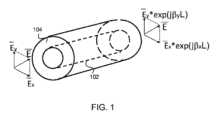
図1は、理想的な光ファイバのモデルの一例を示す。理想的な光ファイバのモデルは、長さLの直線ファイバから構成されてもよい。理想的な光ファイバは、完全に丸いコア102と、機械的応力なしに厳密に軸対称に整列する少なくとも1つのクラッド層104とを有する。X及びY偏光モード

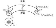
図2は、例示的な実施形態に従う実際の光ファイバの一例を示す。長さLで、例えば、数センチメートルより長いこともある実際のファイバは、例えば、機械的振動、応力、温度勾配等の環境影響下にある場合がある。実際のファイバは曲げられ、実際のファイバの長さに沿った様々な部分が異なるように曲げられることがある。このため、図2に示すように、ファイバに沿って張力と圧縮とが生じることがある。さらに、実際のファイバは、完全なコア及びクラッド形状を有さない場合がある。例えば、実際のファイバのコア202は、わずかに非円形で偏心している場合がある。実際のファイバでは、X偏光モードとY偏光モード
光ファイバを通過する光の偏光状態をより安定なものとし、予測可能にするために、大きな固有複屈折を有するファイバを使用することができる。強い固有複屈折は、例えば、楕円形コアファイバや、ファイバクラッドに埋め込まれた応力印加部、例えばテンションロッド又はボウタイガラス(bow-tie glass)部からなるサイドピットファイバ等の様々な手段に基づいて得ることができる。任意の適切な方法によって引き起こされる強い内部複屈折は、環境影響によって誘発される複屈折を上回る可能性がある。その結果、ファイバの固有複屈折は、ファイバを環境の影響を受けにくくする。したがって、そのようなファイバの出力における偏光の状態は、環境影響下でも安定したままである。 Fibers with large intrinsic birefringence can be used to make the polarization state of light passing through the fiber more stable and predictable. Strong intrinsic birefringence is based on various means such as elliptical core fibers and side-pit fibers consisting of stress-applying sections, such as tension rods or bow-tie glass sections, embedded in the fiber cladding. Obtainable. Strong internal birefringence induced by any suitable method can exceed birefringence induced by environmental influences. As a result, the intrinsic birefringence of the fiber makes it less susceptible to environmental influences. Therefore, the state of polarization at the output of such fibers remains stable even under environmental influences.
偏光状態を安定化させるためのこのアプローチは、電気通信及びセンサシステムにおける用途に使用されることを意図したパッシブ光ファイバに適している可能性がある。パッシブファイバは、例えば、電気通信目的では数百キロメートル、センシングシステムでは数百メートルと長い場合があり、用途の性質上、主に機械的摂動(例えば、曲げ、伸ばし、圧縮)を受けることがある。強い内部複屈折によって偏光状態を安定化させることは、このような機械的摂動の下にあるファイバに有効であると考えられる。 This approach to stabilizing the polarization state may be suitable for passive optical fibers intended for use in applications in telecommunications and sensor systems. Passive fibers can be long, e.g., hundreds of kilometers for telecommunications purposes and hundreds of meters for sensing systems, and by the nature of their application can be subject primarily to mechanical perturbations (e.g., bending, stretching, compression) . Stabilizing the polarization state by strong internal birefringence is believed to be effective in fibers under such mechanical perturbations.
強い内部複屈折のアプローチは、アクティブ光ファイバにも適用してもよい。このようなファイバの例としては、コアの両側のクラッド層に応力印加部を有するボウタイ又はPANDA(偏光保持及び吸収低減)型ファイバが含まれる。 The strong internal birefringence approach may also be applied to active optical fibers. Examples of such fibers include bow-tie or PANDA (polarization maintaining and reducing absorption) type fibers with stress applicators in the cladding layers on either side of the core.
しかしながら、アクティブファイバとパッシブファイバの使用条件は、非常に異なることがある。レーザ又は増幅器におけるアクティブファイバは、比較的短く、例えば、20m未満であり、振動から十分に絶縁され、パッシブファイバとは逆に、動作中に内部加熱される場合がある。例えば、アクティブ光ファイバ内を伝播する2つの波長が存在することがある。その2つとは、(増幅の対象となる)信号波長λsと、より短い波長λpumpを有する励起放射である。信号は、コア内を伝搬することがある。励起放射は、コア内又はクラッド層を伝搬することがある。希土類イオンが励起光子λpumpを吸収すると、励起光子と信号光子とのエネルギー差に等しいエネルギー(量子崩壊)が熱として放出される場合がある。However, the conditions of use for active and passive fibers can be very different. Active fibers in lasers or amplifiers are relatively short, eg, less than 20 m, are well insulated from vibrations, and may heat up internally during operation, contrary to passive fibers. For example, there may be two wavelengths propagating in the active optical fiber. The two are the signal wavelength λs (which is to be amplified) and the pump radiation with the shorter wavelength λpump . A signal may propagate in the core. The excitation radiation may propagate within the core or through the cladding layers. Absorption of an excitation photon λpump by a rare earth ion may result in the release of energy (quantum decay) as heat equal to the energy difference between the excitation photon and the signal photon.
図3は、例示的な実施形態に従って、励起電力に対するアクティブ光ファイバの温度の一例を示す。実線の曲線301は、半径4.6μmのアクティブコアを有するファイバのファイバ中心温度を表し、クラッド層の厚さは200μmである。破線の曲線302は、クラッド層の厚さが315μmである場合のファイバ中心温度を表している。点線の曲線303は、クラッド層の厚さが500μmである場合のファイバ中心温度を表している。対流係数は、1×10⁻³W/(m2K)である。図3から分かるように、コアの温度は、励起電力に対して直線的に上昇している。クラッド層の厚さを増すと温度変化は小さくなるが、最も厚いクラッド層500μmでも、温度変化は、依然として大きい。したがって、励起吸収による内部加熱が、アクティブ光ファイバの温度依存性変化の影響を受けやすくしている。FIG. 3 shows an example of active optical fiber temperature versus pump power, according to an exemplary embodiment. The
光ファイバにおけるリターダンス、例えば、「速い」波と「遅い」波の間の位相シフトは、以下の式

用途によっては、光放射の位相の変化、ファイバ内の機械的応力、光ファイバの加熱による励起吸収の劣化等に焦点が当てられることがある。しかしながら、式1及び式2から導かれるように、ファイバを加熱すると、複屈折が大きく変化する場合がある。そして、複屈折が大きく変化することにより、偏光状態が大きく変化する場合がある。 Some applications focus on changes in the phase of optical radiation, mechanical stresses in the fiber, degradation of excitation absorption due to heating of the optical fiber, and the like. However, as can be derived from Eqs. 1 and 2, heating the fiber can significantly change the birefringence. A large change in birefringence may cause a large change in the polarization state.
図4は、複屈折コア材料の温度感度を測定するための実験のスキームを示す。セットアップは、アイソレータ402を介して放射(光信号)を試験中のアクティブファイバ403に発射するように構成されたレーザダイオード401を備える。セットアップは、ダイクロイックミラー405を介してアクティブファイバ403に励起放射を発射するように構成された励起ダイオード404と、アクティブファイバ403から出る増幅された放射の偏光を分析するための偏光計406(PAX1000IR1/m)とをさらに備える。 FIG. 4 shows an experimental scheme for measuring the temperature sensitivity of birefringent core materials. The setup comprises a
最初の実験では、1064nmの100%直線偏光半導体ファイバ結合レーザダイオードの放射を、シングル偏光モード(1つの固有状態)が励起されるようにPANDA型複屈折ダブルクラッド・イッテルビウムドープ先細ファイバに(スプライシングによって)発射させた。複屈折アクティブ先細ファイバの長さは5mで、ファイバは35cmのリング状に巻き、25mmの偏光ビート長を有している。コアの複屈折は、B=0.4*10-4である。波長976nmの励起光は、レンズとダイクロイックミラー405を用いて、アクティブイッテルビウム添加先細ファイバの広幅側のクラッドに発射された。増幅された放射の偏光状態(方位角、楕円率、偏光消光率)を偏光計406で解析した。この実験では、増幅された放射の偏光状態の依存性を、クラッドに発射される励起電力放射の関数として測定した。温度は、ファイバの幅端から5cmの距離で測定された。実験中、ファイバを冷却するための特別な措置は施されていない。その結果を図5及び図6に示す。In the first experiment, the radiation of a 1064 nm 100% linearly polarized semiconductor fiber-coupled laser diode was spliced into a PANDA-type birefringent double-clad ytterbium-doped tapered fiber such that a single polarization mode (one eigenstate) was excited. ) fired. The length of the birefringent active tapered fiber is 5m, the fiber is wound in a 35cm ring and has a polarization beat length of 25mm. The birefringence of the core is B=0.4*10−4 . Excitation light with a wavelength of 976 nm was launched into the wide-side cladding of the active ytterbium-doped tapered fiber using a lens and
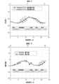
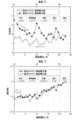
図5は、PANDA型アクティブ先細光ファイバの励起電力に対する偏光安定性と温度の一例を示す。黒い点線は励起電力を増加させたときの偏光状態、白い点線は励起電力を減少させたときの偏光状態を表している。実験結果から分かるように、励起電力を0から約22.5Wまで上げると、ファイバ温度が2℃上昇し(24℃から26℃に)、SOPの方位が分散9.41°、標準偏差3.07°で周期的に変化する(上のグラフ)。方位の平均値は、-22.69°、最小値と最大値は、それぞれ-26.02°と-17.21°であった。同時に楕円率(下のグラフ)も変化し、分散は7.97°、標準偏差は、2.82°であった。楕円率の平均値は、-5.68°で、最小値と最大値は、それぞれ-10.07°と-1.8°であった。 FIG. 5 shows an example of polarization stability versus temperature for a PANDA-type active tapered optical fiber versus pump power. The black dotted line represents the polarization state when the excitation power is increased, and the white dotted line represents the polarization state when the excitation power is decreased. As can be seen from the experimental results, increasing the pump power from 0 to about 22.5 W increases the fiber temperature by 2° C. (from 24° C. to 26° C.) and the orientation of the SOP with a dispersion of 9.41° and a standard deviation of 3.5° C. 07° (upper graph). The average azimuth value was -22.69°, and the minimum and maximum values were -26.02° and -17.21°, respectively. At the same time, the ellipticity (bottom graph) also changed, with a variance of 7.97° and a standard deviation of 2.82°. The average ellipticity was -5.68° and the minimum and maximum values were -10.07° and -1.8°, respectively.
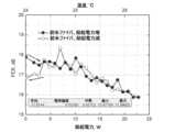
図6は、PANDA型アクティブ先細光ファイバの励起電力に対する偏光消光率の一例を示す。偏光消光率(PER)は、所望の偏光のパワーと所望でない偏光のパワーとを比較する指標である。図7に示すように、ファイバの温度が2℃変化しただけで,PERは6.11dBの分散と2.47dBの標準偏差で変化する。また、PERの平均値は10.63dB、最小値と最大値はそれぞれ7.51dBと15.03dBであった。 FIG. 6 shows an example of polarization extinction versus excitation power for a PANDA-type active tapered optical fiber. Polarization extinction ratio (PER) is a measure that compares the power of the desired polarized light to the power of the undesired polarized light. As shown in FIG. 7, a 2° C. change in fiber temperature changes the PER with a dispersion of 6.11 dB and a standard deviation of 2.47 dB. Also, the average value of PER was 10.63 dB, and the minimum and maximum values were 7.51 dB and 15.03 dB, respectively.
励起電力の増加時と減少時の偏光状態の違いから、偏光状態の変化はヒステリシスを伴い、このような応力誘起複屈折を有するアクティブファイバは、発射された励起電力履歴に関するメモリを示す。この測定に基づいて、22Wの励起電力吸収による内部加熱が偏光状態のドリフトを引き起こしていることが観察された。 The change in polarization state is accompanied by hysteresis due to the difference in polarization state when the pump power is increased and decreased, and active fibers with such stress-induced birefringence exhibit memory on the launched pump power history. Based on this measurement, it was observed that the internal heating due to absorption of the 22 W excitation power caused the polarization state drift.
したがって、この実験に基づき、以下の観察が可能である。1)複屈折の強いアクティブファイバにおける増幅光の偏光状態は、打ち出された励起電力に大きく依存する。2)偏光状態はヒステリシスを伴って変化し、発射された励起電力の履歴に関するメモリを有する。このため、偏光状態の挙動は、予測不可能である。 Therefore, based on this experiment, the following observations are possible. 1) The polarization state of amplified light in an active fiber with strong birefringence is highly dependent on the pump power launched. 2) The polarization state changes with hysteresis and has memory for the history of the emitted excitation power. Hence, the polarization state behavior is unpredictable.
式2に基づいて、固有複屈折が小さい場合(B→0)、(dB/dt)*ΔT<<Bとなり、その結果、偏光状態の温度感度はゼロになる傾向がある(すなわち、dR→0)。したがって、ファイバの固有複屈折が小さければ小さいほど、ファイバの偏光感度は低くなる。例えば、ファイバの励起時にリターダンスの変化が小さくなる。これとは対照的に、高複屈折ファイバは、温度感度が強い場合がある。 Based on Equation 2, when the intrinsic birefringence is small (B→0), (dB/dt)*ΔT<<B, and as a result the temperature sensitivity of the polarization state tends to zero (i.e., dR→ 0). Therefore, the lower the intrinsic birefringence of the fiber, the lower the polarization sensitivity of the fiber. For example, the retardance changes less when pumping the fiber. In contrast, highly birefringent fibers can be highly temperature sensitive.
強い温度感受性のために、温度が変化すると複屈折が劇的に変化する。さらに、上述したように、内部複屈折の変化は、ヒステリシスを伴って不可逆的に起こる。アニールの際には、内部複屈折の増大と減少の両方が起こる可能性がある。複屈折の変化はヒステリシスを伴って起こるため、高複屈折ファイバはファイバの加熱履歴に対して複屈折を記憶していることになる。それにもかかわらず、用途の性質(例えば、光伝送のための透明媒体)により、高複屈折光ファイバは、著しい温度変化にさらされない場合があり、したがって、上述の特性は、例えば、パッシブ光ファイバ又は比較的低い励起電力を有するアクティブ光ファイバとしての利用を一般に妨げない。 Due to the strong temperature sensitivity, the birefringence changes dramatically as the temperature changes. Furthermore, as mentioned above, the change in internal birefringence occurs irreversibly with hysteresis. Both an increase and a decrease in internal birefringence can occur during annealing. Since the birefringence change occurs with hysteresis, the high birefringence fiber remembers the birefringence with respect to the heating history of the fiber. Nevertheless, due to the nature of the application (e.g. transparent media for optical transmission), highly birefringent optical fibers may not be exposed to significant temperature changes, and thus the above properties may be used, for example, in passive optical fibers or generally does not preclude its use as an active optical fiber with relatively low pump power.
低い固有複屈折を有するファイバは、様々な方法で製造することができる。低い固有複屈折を得るための1つの方法は、光ファイバをできるだけ理想に近づけること、例えば、内部応力が低い状態でファイバを極めて対称的にすることである。低い固有複屈折を得るための別の方法は、補償ファイバを適用することである。低いレベルの内部複屈折は、例えば、応力複屈折(Bs)と幾何学的形状複屈折(Bc)との合計がゼロになるようにファイバドーパント材料を選択することによって達成することができる。低い固有複屈折を得るためのもう一つの方法は、紡糸ファイバを使用することである。ファイバプリフォームを引っ張りながら高速で紡糸すると、内部複屈折が小さくなる。プリフォームを紡糸すると、ファイバに沿って高速複屈折軸と低速複屈折軸が周期的に入れ替わり、偏光固有モード間の相対位相遅延が断片的に補償される。Fibers with low intrinsic birefringence can be produced in a variety of ways. One way to obtain low intrinsic birefringence is to make the optical fiber as close to ideal as possible, eg, to make the fiber highly symmetrical with low internal stress. Another way to obtain low intrinsic birefringence is to apply compensating fibers. Low levels of internal birefringence can be achieved, for example, by choosing fiber dopant materials such that the sum of stress birefringence (Bs ) and geometry birefringence (Bc ) is zero. . Another way to obtain low intrinsic birefringence is to use spun fibers. Spinning at high speed while pulling the fiber preform reduces the internal birefringence. Spinning the preform periodically alternates the fast and slow birefringence axes along the fiber to piecewise compensate the relative phase delays between the polarization eigenmodes.
例示的な実施形態によれば、低い固有複屈折を有するアクティブ光ファイバが提供される。そのようなファイバのSOP安定性は、図4の実験セットアップで検証された。SOP安定性の実験的検証のために、Ybドープ紡糸アクティブダブルクラッド先細ファイバを製造した。紡糸ファイバの製造は、ファイバプリフォームを角速度600rev/minで回転させながら、アクティブ先細ファイバを引き抜く方法で行った。この実験では、波長1064nmの直線偏光半導体レーザからの発光を、ファイバ結合アイソレータ402を介して紡糸先細ファイバにスプライシングすることにより発射された。紡糸先細ファイバの長さは2.8mで、幅の広い部分で6mmピッチであった。ピッチは、回転の周期、例えば、紡糸ファイバが360°回転する長さを指す場合がある。ピッチは、ファイバを引っ張る速度及び回転の角速度に依存することがある。ファイバの残留線形複屈折は3.21*10-6、円形複屈折は6.88*10-6であった。ファイバは、直径35cmのリング状に巻き取られた。976nmの励起光は、レンズとダイクロイックミラー405を介して、アクティブファイバのクラッドに発射された。According to exemplary embodiments, active optical fibers with low intrinsic birefringence are provided. The SOP stability of such fibers was verified in the experimental setup of FIG. Yb-doped spun active double-clad tapered fibers were fabricated for experimental verification of SOP stability. The spun fiber was produced by drawing the active tapered fiber while rotating the fiber preform at an angular velocity of 600 rev/min. In this experiment, emission from a linearly polarized semiconductor laser with a wavelength of 1064 nm was launched by splicing it through a fiber-coupled
偏光計405を用いて、増幅された放射の偏光状態(方位角、楕円率、PER)を分析した。増幅された放射の偏光状態の依存性を、発射された励起電力の関数として再び調査した。実験中にファイバを強制的に冷却するような措置は講じていない。その結果を図7と図8に示す。 A
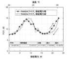
図7は、紡糸アクティブ先細光ファイバの励起電力に対する偏光安定性と温度の一例を示す。実験結果から分かるように、励起電力をゼロから約20Wまで上げると、ファイバ温度が2℃上昇し(24℃から26℃に)、方位が分散0.12°、標準偏差0.35°で周期的に変化する(上のグラフ)。方位の平均値は1.39°、最小値と最大値はそれぞれ0.11°と1.97°であった。同時に、楕円率(下のグラフ)は、分散0.03°、標準偏差0.18°で変化した。楕円率の平均値は1.15°、最小値と最大値はそれぞれ0.93°と1.48°であった。 FIG. 7 shows an example of polarization stability versus temperature for a spun active tapered optical fiber versus pump power. As can be seen from the experimental results, increasing the pump power from zero to about 20 W increases the fiber temperature by 2° C. (from 24° C. to 26° C.), and the orientation is periodic with a dispersion of 0.12° and a standard deviation of 0.35°. (upper graph). The average value of orientation was 1.39°, and the minimum and maximum values were 0.11° and 1.97°, respectively. At the same time, the ellipticity (bottom graph) changed with a variance of 0.03° and a standard deviation of 0.18°. The average ellipticity was 1.15°, and the minimum and maximum values were 0.93° and 1.48°, respectively.
図8は、紡糸アクティブ先細光ファイバの励起電力に対する偏光消光率の一例を示す。図8に示すように、ファイバ温度が2℃変化すると、PERは分散0.43dB、標準偏差0.65dBで変化している。PERの平均値は17.01dBで、最小値と最大値はそれぞれ15.88dBと17.90dBであった。 FIG. 8 shows an example of polarization extinction versus excitation power for a spun active tapered optical fiber. As shown in FIG. 8, when the fiber temperature changes by 2° C., the PER changes with a dispersion of 0.43 dB and a standard deviation of 0.65 dB. The average PER was 17.01 dB, with minimum and maximum values of 15.88 dB and 17.90 dB, respectively.
図5~図8の結果に基づくと、アクティブ紡糸ファイバの偏光状態の変化は、PANDA型ファイバに比べて、低複屈折紡糸ファイバの方が著しく小さい。表1は、PANDA型ファイバと紡糸ファイバの比較データを示す。表1から分かるように、偏光状態の安定性(例えば、方位角及び楕円率の偏差)は、紡糸アクティブ先細ファイバが1桁優れている。楕円率の分散は、2桁も良好である。 Based on the results of FIGS. 5-8, the change in the polarization state of the active spun fiber is significantly smaller in the low birefringence spun fiber compared to the PANDA type fiber. Table 1 shows comparative data for PANDA-type fibers and spun fibers. As can be seen from Table 1, the stability of the polarization state (eg, azimuthal and ellipticity deviations) is an order of magnitude better for the spun active tapered fiber. The ellipticity variance is two orders of magnitude better.
表1.PANDA型アクティブファイバと紡糸アクティブファイバのSOP変動の比較(励起電力22W)。
上記の実験は、例えば、PANDA型ファイバのような高複屈折ファイバを用いた増幅器と比較して、低複屈折アクティブ光ファイバがSOP安定性の点で著しく優れていることを実証している。 The above experiments demonstrate that low-birefringence active optical fibers are significantly superior in terms of SOP stability compared to amplifiers using high-birefringence fibers, eg, PANDA-type fibers.
例示的な実施形態は、発射された励起電力から十分に独立している安定した偏光状態を可能にする、異なるタイプのアクティブ光ファイバを提供する。例示的な実施形態は、例えば、コアにおける低い固有複屈折との組み合わせで先細縦プロファイルを有する又は有しないシングルクラッド又はダブルクラッドのアクティブ光ファイバのセクションを提供する。例示的な実施形態によれば、アクティブコアの複屈折は、10-5未満であってもよい。例示的な実施形態によれば、アクティブコアの線形複屈折は、10-5未満であってもよい。例示的な実施形態によれば、アクティブコアの円形複屈折は、10-5未満であってもよい。例示的な実施形態によれば、アクティブコアの円形複屈折及び線形複屈折の両方は、10-5未満であってもよい。実験に基づくと、10-5未満の複屈折値は、アクティブ光ファイバの内部加熱による温度変化に対して十分に安定した偏光状態を提供し得る。一般に、複屈折を小さくすることで、偏光状態の安定性を向上させることができる。例えば、10-5未満、例えば10-6<B<10-5の範囲内の複屈折値は、さらに安定した偏光状態を提供し、このことは、例えば、より長いファイバ長L又はより高い励起電力で有益であり得る。例示的な実施形態によれば、アクティブコアの複屈折は、図6及び図7に関連して説明したアクティブ紡糸ファイバに従うことができる。例えば、アクティブコアの線形複屈折は、3.2*10-6であってもよい。アクティブコアの円形複屈折は、6.7*10-6であってもよい。Exemplary embodiments provide different types of active optical fibers that enable stable polarization states that are largely independent of the launched pump power. Exemplary embodiments, for example, provide sections of single-clad or double-clad active optical fiber with or without a tapered longitudinal profile in combination with low intrinsic birefringence in the core. According to exemplary embodiments, the active core may have a birefringence of less than 10−5 . According to an exemplary embodiment, the linear birefringence of the active core may be less than 10−5 . According to exemplary embodiments, the circular birefringence of the active core may be less than 10−5 . According to exemplary embodiments, both circular and linear birefringence of the active core may be less than 10−5 . Based on experiments, birefringence values less than 10−5 can provide a sufficiently stable polarization state against temperature changes due to internal heating of the active optical fiber. In general, the stability of the polarization state can be improved by reducing the birefringence. For example, a birefringence value less than 10−5 , such as in the
図9は、例示的な実施形態に従って、アクティブシングルクラッド光ファイバの縦断面の一例を示す。アクティブ光ファイバのセクションは、アクティブコア901を備えてもよい。コアは、例えば、二酸化ケイ素のような任意の適切な材料から構成されてもよい。アクティブコア901は、少なくとも1つの希土類元素をさらに含んでもよい。アクティブコア901は、励起放射がアクティブコア901に発射されたときに、アクティブコア901に発射された光信号の増幅を可能にするために、希土類元素でドープされていてもよい。アクティブ光ファイバのセクションは、クラッド層902をさらに備えてもよい。アクティブコア901は、第一の屈折率ncoreを有してもよい。クラッド層902は、第二の屈折率ncladを有してもよい。断面の屈折率プロファイル903に示されるように、第二の屈折率ncladは、第一の屈折率ncladより小さくてもよい。アクティブコアの複屈折は、上述したように、10-5未満であってもよい。例えば、低速偏光モードの屈折率nslowと高速偏光モードの屈折率nfastとの差は、10-5より小さくてもよく、すなわち、B=nslow-nfast<10-5であってもよい。FIG. 9 shows an example longitudinal cross-section of an active single-clad optical fiber, according to an exemplary embodiment. A section of active optical fiber may comprise an
アクティブコア901は、シングルモード動作をサポートするように構成されてもよい。例えば、アクティブコア901は、光信号のシングルモード動作のための伝搬条件を満たしてもよい。伝搬条件は、2πrNA/λ<2.405を含んでもよく、ここで、rはアクティブコアの半径、NAはアクティブコアの開口数、λは光信号の波長である。図9に示すように、アクティブコア901は、光信号及び励起放射を受信するように構成されてもよい。言い換えれば、光信号は、アクティブコア901、例えば、アクティブコア901の一端において発射されてもよい。励起放射は、アクティブコア901のセクションのいずれか一端又は両端で受信されるように構成されてもよいし、発射されてもよい。
図10は、例示的な実施形態に従って、アクティブダブルクラッド光ファイバの縦断面の一例を示す。アクティブ光ファイバのセクションは、アクティブコア1001から構成されてもよい。アクティブコア1001は、第一の屈折率ncoreを有してもよい。アクティブ光ファイバのセクションは、アクティブコア1001の周囲に内側クラッド層1002をさらに備えてもよい。内側クラッド層1002は、第二の屈折率nclad1を有してもよい。アクティブ光ファイバのセクションは、内側クラッド層1002の周囲に外側クラッド層1003をさらに備えてもよい。外側クラッド層1003は、第三の屈折率nclad2を有してもよい。断面の屈折率プロファイル1004に示されるように、第一の屈折率ncoreは第二の屈折率nclad1より小さくてもよく、第三の屈折率nclad2は第二の屈折率nclad1より小さくてもよい。アクティブコア1001の複屈折は、10-5未満であってもよい。アクティブコア1001は、光信号を受信するように構成されてもよい。言い換えれば、光信号は、アクティブコア1001で発射されてもよい。内側クラッド層1002は、アクティブ光ファイバのセクションのいずれか一端又は両端から励起放射を受信するように構成されてもよい。言い換えれば、励起放射は、アクティブ光ファイバのセクションのいずれか一端又は両端で、内側クラッド層1002に発射されてもよい。FIG. 10 shows an example longitudinal cross-section of an active double-clad optical fiber, according to an exemplary embodiment. A section of active optical fiber may consist of an
アクティブコアの複屈折が小さいと、励起動作によって引き起こされる内部加熱に対する耐性を向上する。比較的薄いシングルモードコアは、幅の広いマルチモードコアよりも励起電力による内部加熱の影響を受けやすい場合があるので、先細でないシングルモードアクティブコアの複屈折が低いと、有益なことがある。例えば、シングルモードコアの直径が小さいと、表面積が小さくなり、その結果、熱を放散する能力が規定される。シングルモードコアの複屈折が小さいと、シングルモードファイバ内でより高い電力の励起放射を発射できるため、偏光状態を十分に安定させながら、光信号をより適切に増幅することができる。 The low birefringence of the active core improves resistance to internal heating caused by excitation motion. Low birefringence in non-tapered single-mode active cores can be beneficial, since relatively thin single-mode cores can be more susceptible to internal heating due to pump power than wider multimode cores. For example, the small diameter of the single mode core dictates the small surface area and consequently the ability to dissipate heat. The low birefringence of the single-mode core allows higher power pump radiation to be launched in the single-mode fiber, which allows for better amplification of the optical signal while keeping the polarization state sufficiently stable.
図11は、例示的な実施形態に従って、アクティブ先細シングルクラッド光ファイバの縦断面の一例を示す。アクティブ光ファイバのセクションは、アクティブコア1101及びクラッド層1102を備えてもよく、これらは、図9のアクティブコア901及びクラッド層902と同様であってもよい。しかしながら、アクティブ光ファイバのセクションは、アクティブコア1101の直径dがアクティブ光ファイバのセクションの長さLに沿って徐々に変化し、それによって先細縦プロファイルを形成するような先細縦プロファイルを有してもよい。その結果、アクティブ光ファイバのセクションは、第一の部分と第二の部分とを備えてもよく、アクティブコアの第一の部分の半径はアクティブコアの第二の部分の半径よりも小さい。さらに、クラッド層1102の厚さは、先細縦プロファイルに沿って徐々に変化してもよい。例えば、クラッド層1102の厚さは、アクティブコア1101の対応する部分の直径dに比例してもよい。 FIG. 11 illustrates an example longitudinal cross-section of an active tapered single-clad optical fiber, according to an exemplary embodiment. A section of active optical fiber may comprise an active core 1101 and
アクティブコアの第一の部分は、光信号のシングルモード動作のための伝搬条件を満たすように構成されてもよい。アクティブコアの残りの部分、例えば、第二の部分は、光信号のマルチモード動作をサポートするように構成されてもよい。伝搬条件は、2πrNA/λ<2.405を含んでもよく、ここで、rはアクティブコアの第一の部分の半径(d/2)、NAはアクティブコアの第一の部分の開口数、λは光信号の波長である。アクティブコアの第一の部分は、光信号を受信するように構成されていてもよい。言い換えれば、光信号は、アクティブコア1101の第一の部分で発射されてもよい。アクティブコア1101の第一の部分及び/又は第二の部分は、励起放射を受信するように構成されてもよい。言い換えれば、励起放射は、アクティブコア1101の第一の部分及び/又は第二の部分において発射されてもよい。 The first portion of the active core may be configured to meet propagation conditions for single-mode operation of optical signals. A remaining portion of the active core, eg, the second portion, may be configured to support multimode operation of the optical signal. Propagation conditions may include 2πrNA/λ<2.405, where r is the radius of the first portion of the active core (d/2), NA is the numerical aperture of the first portion of the active core, and λ is the wavelength of the optical signal. A first portion of the active core may be configured to receive an optical signal. In other words, the optical signal may be launched in the first portion of active core 1101 . A first portion and/or a second portion of active core 1101 may be configured to receive excitation radiation. In other words, excitation radiation may be emitted at the first portion and/or the second portion of active core 1101 .
例示的な実施形態によれば、アクティブコア1101の第一の部分は、アクティブ光ファイバのセクションの第一端に配置されてもよく、アクティブコア1101の第二の部分は、アクティブ光ファイバのセクションの第二端に配置されてもよい。例示的な実施形態によれば、アクティブコア1101の第一の部分は、アクティブコア1101の狭端部を構成していてもよい。アクティブコア1101の第二の部分は、アクティブコア1101の幅の広端部を構成してもよい。 According to an exemplary embodiment, a first portion of active core 1101 may be disposed at a first end of a section of active optical fiber and a second portion of active core 1101 may be located at the section of active optical fiber. may be located at the second end of the According to an exemplary embodiment, the first portion of active core 1101 may constitute the narrow end of active core 1101 . The second portion of active core 1101 may constitute the wide end of active core 1101 .
先細アクティブコア1101の第一の部分で光信号を発射することにより、アクティブコア1101の第二の部分(マルチモード)においても基本モードのみの伝搬を手配することができる。アクティブコア1101の第二の部分直径がより大きいと、高効率で高出力低強度励起源からの励起放射をアクティブ先細ファイバに発射することが可能になる。アクティブ光ファイバの先細コアの複屈折がより小さいと、シングルモード光信号のために十分に安定した偏光状態を維持しながら、第二の部分のより高い励起電力発射能力の恩恵を受けることが可能になる。例示的な実施形態によれば、例えば、低い非線形性で所望の利得を達成するために、励起放射の約90%が、アクティブコア1101の第二の部分に発射されてもよい。励起放射の約10%は、例えば、アクティブコア1101の飽和を引き起こすために、アクティブコア1101の第一の部分に発射されてもよい。 By launching an optical signal in the first portion of the tapered active core 1101, propagation of only the fundamental mode can be arranged in the second portion (multimode) of the active core 1101 as well. The larger second portion diameter of the active core 1101 enables high efficiency launch of pump radiation from a high power, low intensity pump source into the active tapered fiber. The smaller birefringence of the tapered core of the active optical fiber can benefit from the higher pump power launch capability of the second section while maintaining a sufficiently stable polarization state for single-mode optical signals. become. According to an exemplary embodiment, approximately 90% of the pump radiation may be launched into the second portion of active core 1101, eg, to achieve a desired gain with low nonlinearity. About 10% of the excitation radiation may be launched into the first portion of active core 1101 to cause saturation of active core 1101, for example.
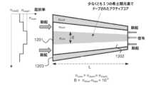
図12は、例示的な実施形態に従って、アクティブ先細ダブルクラッド光ファイバの縦断面の一例を示す。アクティブ光ファイバのセクションは、図10のアクティブコア1001、クラッド層1002及び1003と同様のアクティブコア1201、内側クラッド層1202、及び外側クラッド層1203を備えてもよい。しかしながら、アクティブ光ファイバのセクションは、先細縦プロファイルを有してもよい。例えば、アクティブコア1201の直径dは、アクティブ先細光ファイバのセクションの長さLに沿って徐々に変化してもよい。さらに、内側及び/又は外側クラッド層の厚さは、先細縦プロファイルに沿って徐々に変化してもよい。例えば、内側及び/又は外側クラッド層の厚さは、アクティブコア1201の対応する部分の直径dに比例してもよい。 FIG. 12 illustrates an example longitudinal cross-section of an active tapered double-clad optical fiber, according to an exemplary embodiment. A section of active optical fiber may comprise an
例示的な実施形態によれば、アクティブコア1201は、図11のアクティブコア1101と同様の第一及び第二の部分を備えてもよい。例示的な実施形態によれば、アクティブ光ファイバのセクションは、アクティブコア1201の第一の部分の周りの内側クラッド層1202の第一の部分と、アクティブコア1201の第二の部分の周りの内側クラッド層1202の第二の部分とを備えてもよい。内側クラッド層1202の第一の部分の厚さは、内側クラッド層1202の第二の部分の厚さよりも小さくてよい。内側クラッド層1202の第一の部分及び/又は第二の部分は、励起放射を受信するように構成されてもよい。言い換えれば、励起放射は、内側クラッド層1202の第一の部分及び/又は第二の部分において発射されてもよい。内側クラッド層1202の第二の部分の厚さが大きいと、より高い出力の励起放射線を先細ファイバに発射することが可能になる。アクティブ光ファイバの先細コアの複屈折が小さいと、シングルモード光信号のための偏光の十分に安定した状態を維持しながら、内側クラッド層1202の第二の部分のより高い励起電力発射能力の恩恵を受けることが可能になる。 According to an exemplary embodiment,
例示的な実施形態によれば、内側クラッド層1202の第一の部分は、アクティブ光ファイバのセクションの第一端に配置されてもよく、内側クラッド層1202の第二の部分は、アクティブ光ファイバの第二端に配置されてもよい。例示的な実施形態によれば、内側クラッド層1202の第一の部分は、内側クラッド層の狭端部を構成してもよい。内側クラッド層1202の第二の部分は、内側クラッド層の広端部を構成してもよい。 According to an exemplary embodiment, a first portion of
図9~図12に図示されていないとしても、アクティブ光ファイバのセクションは、例えば、クラッド層の周りに1つ以上の被覆層等の追加の構造をさらに備えてもよい。被覆層は、例えば、ポリマー被覆から構成されてもよい。被覆層は、固有複屈折が低いアクティブコア901、1001、1101、1201において外部複屈折を導入させる可能性のある環境影響を低減するように構成されてもよい。したがって、1つ以上の被覆層と結合して低い内部複屈折は、一緒になって、変化する(内部/外部)温度及び機械的曲げ等の他の環境影響の下で、十分に安定した偏光状態を提供するアクティブ光ファイバを提供する。上記の例示的な実施形態において、励起放射は、光信号と同じ又は実質的に同じ方向に、及び/又は光信号と反対又は実質的に反対の方向に伝搬するように構成されてもよい。 Although not shown in FIGS. 9-12, the section of active optical fiber may further comprise additional structures such as, for example, one or more coating layers around the cladding layer. The covering layer may, for example, consist of a polymer coating. The cladding layers may be configured to reduce environmental effects that may introduce external birefringence in
図13は、例示的な実施形態に従って、ファイバレーザデバイス1300の一例を示す。ファイバレーザデバイス1300は、アクティブ光ファイバ1301を備えてもよい。アクティブ光ファイバ1301は、上述した異なるタイプのアクティブ光ファイバ、又はそのセクションのいずれかを備えてもよい。ファイバレーザデバイス1300は、一対の反射鏡の間で往復しながら、アクティブ光ファイバ1301の内部で増幅された出力放射を提供するように構成されてもよい。ファイバレーザデバイス1300は、励起放射源1305を備えてもよい。励起放射源は、励起放射結合器1304に光学的に接続されてもよい。励起放射源は、適切な電力で励起放射を発生させるように構成されてもよい。励起放射結合器1304は、励起放射源1305からの放射をアクティブ光ファイバ1301に結合するように構成されてもよい。励起放射結合器1304は、例えば、マルチモード励起コンバイナ、自由空間レンズシステム、及び/又はシングルクラッドファイバ用の波長依存マルチプレクサ(WDM)を備えてもよい。マルチモード励起コンバイナは、タイプ(1+n)*1であってもよく、これは、1つの入力信号ファイバ及びn個の励起ファイバが、例えば、先細リングによって、1つの信号出力ファイバに一緒に結合されることを示すことができる。そのようなマルチモード励起コンバイナの例は、(1+6)*1コンバイナであり、これは、6つの励起ファイバと1つの信号ファイバとを一緒に結合させる。励起放射結合器1304は、励起放射をアクティブ光ファイバ1301の適切な部分及び/又は層に発射するように構成されてもよい。例えば、シングルクラッドファイバの場合、励起放射結合器1304は、励起源1305から発した励起放射をアクティブ光ファイバ1301のコアに発射するように構成されてもよい。ダブルクラッドファイバの場合、励起放射結合器1304は、励起源1305から発した励起放射をアクティブ光ファイバ1301のコアに発射するように構成されてもよい。励起放射結合器1304は、アクティブ光ファイバ1301の第一端に光学的に接続されてもよい。光学的に接続されることにより、2つの光学的に接続又は光学的に結合された構成要素の間で光が伝搬することが可能になることがある。光学的接続は、光学的に接続された構成要素の間に、例えば、ミラー又は励起放射結合器等の中間構成要素が存在しないような直接的な光学的接続を含んでもよい。 FIG. 13 shows an example
ファイバレーザデバイス1300は、第二の励起放射源1307及び第二の励起放射結合器1306をさらに備えてもよく、これらは、それぞれ励起結合器1304及び励起放射源1305と同様であってもよい。しかしながら、励起放射結合器1306は、アクティブ光ファイバ1301の第二端に、例えば、出力端に光学的に接続されてもよい。さらに、励起放射源1307は、励起放射源1305から生じる励起放射と比較して異なるパワーレベルを有する励起放射を生成するように構成されてもよい。例えば、アクティブ先細光ファイバの場合、励起放射源は、アクティブ光ファイバ1301の第一端に光学的に接続されてもよく、アクティブ光ファイバ1301の第二端よりも薄くてもよい。第二の励起放射源1307のパワーレベルは、上述したように、励起放射源1305のパワーレベルより高くてもよい。
ファイバレーザデバイス1300は、第一の反射鏡1302をさらに備えてもよく、これは、アクティブ光ファイバ1301の第一端に光学的に接続されてもよい。第一の反射鏡1302は、励起結合器1304からアクティブ光ファイバ1301に励起放射を伝達するように構成されてもよい。第一の反射鏡1302は、アクティブ光ファイバ1301内を第一の反射鏡1302に向かって伝搬する光の大部分を反射するように構成されてもよい。第一の反射鏡1302は、例えば、自由空間バルク誘電体又は金属被覆ミラー、アクティブ光ファイバ1301の第一端にスプライシングされた別の光ファイバで書き込まれたファイバブラッググレーティング(FBG)、ファイバループミラー、又はファイバ結合ファラデー回転ミラーを備えてもよい。あるいは、アクティブ光ファイバ1301の第一端にファイバブラッググレーティングを書き込んでもよい。第一の反射鏡の反射率は、例えば、90%以上であってもよい。
ファイバレーザデバイス1300は、第二の反射鏡1303をさらに備えてもよく、これは、アクティブ光ファイバ1301の第二端に、例えば出力端に光学的に接続されてもよい。第二の反射鏡1303は、励起結合器1306からアクティブ光ファイバ1301に励起放射を伝達するように構成されてもよい。第二の反射鏡1303は、ファイバレーザデバイス1300から増幅された光を出力できるように、アクティブ光ファイバ内で第二の反射鏡1303に向かって伝搬する光の一部を通過させるように構成されていてもよい。第二の反射鏡1303は、例えば、自由空間バルク誘電体又は金属被覆ミラー、アクティブ光ファイバ1301の第二端に書き込まれた又はスプライシングされたファイバブラッググレーティング(FBG)、又はファイバループミラーを備えてもよい。第二の反射鏡の反射率は、例えば、90%未満であってもよい。 The
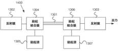
図14は、例示的な実施形態に従うファイバレーザデバイス1400の別の例を示す。ファイバレーザデバイス1400は、ファイバレーザデバイス1300と同様の構成要素を備えてもよい。しかしながら、構成要素のいくつかは、異なる順序で配置されてもよい。例えば、第一の反射鏡1302は、励起放射結合器1304に光学的に接続されてもよく、励起放射結合器1304は、アクティブ光ファイバ1301の第一端に光学的に接続されてもよい。さらに、第二の反射鏡1303は、励起放射結合器1306に光学的に接続されてもよく、励起放射結合器1306は、アクティブ光ファイバ1301の第二端に光学的に接続されてもよい。励起放射結合器1304及び1306は、反射鏡1302と1303との間で反射されてアクティブ光ファイバ1301での光の増幅を可能にするように光を搬送するように構成されてもよい。 FIG. 14 shows another example of a
図15は、例示的な実施形態に従うファイバレーザデバイス1500の別の例を示す。ファイバレーザデバイス1500は、ファイバレーザデバイス1300と同様の構成要素を備えてもよい。しかしながら、構成要素のいくつかは、異なる順序で配置されてもよい。この例では、図14と同様に、第一の反射鏡1302は、励起放射結合器1304に光学的に接続されてもよく、励起放射結合器1304は、アクティブ光ファイバ1301の第一端に光学的に接続されてもよい。出力側では、図13と同様に、第二の反射鏡1303がアクティブ光ファイバ1301の第二端に光学的に接続され、励起放射結合器1306が第二の反射鏡1303に結合されてもよい。 FIG. 15 shows another example of a
図16は、例示的な実施形態に従うファイバレーザデバイス1600の別の例を示す。ファイバレーザデバイス1500は、ファイバレーザデバイス1300と同様の構成要素を備えてもよい。しかしながら、構成要素のいくつかは、異なる順序で配置されてもよい。この例では、第一の反射鏡1302は、図13と同様に、励起放射結合器1304に光学的に接続されてもよく、励起放射結合器1304は、アクティブ光ファイバ1301の第一端に光学的に接続されてもよい。出力側では、第二の反射鏡1303がアクティブ光ファイバ1301の第二端に光学的に接続され、励起放射結合器1306が第二の反射鏡1303に結合されてもよい。 FIG. 16 shows another example of a
図17は、例示的な実施形態に従うファイバマスタ発振器電力増幅器デバイス(MOPA)1700の一例を示す。ファイバマスタ発振器電力増幅器デバイス1700は、上述したように、異なるタイプのアクティブ光ファイバ、又はそのセクションのいずれかを備えてもよい。さらに、ファイバマスタ発振器電力増幅器デバイス1700は、図13のものと同様の励起放射源1305及び/又は励起放射源1307を備えてもよい。ファイバマスタ発振器電力増幅器デバイス1700は、図13のものと同様の励起放射結合器1304及び/又は第二の励起放射結合器1306をさらに備えてもよい。励起放射結合器1304は、アクティブ光ファイバ1301の第一端に結合され、アクティブ光ファイバ1301にて励起放射源1305で生じる励起放射を発射するように構成されてもよい。第二の励起放射結合器1306は、アクティブ光ファイバ1301の第二端に光学的に結合され、アクティブ光ファイバ1301にて励起放射源1307で生じる励起放射を発射するように構成されてもよい。第二の励起放射結合器1306は、アクティブ光ファイバ1301から出力放射を提供するように、さらに構成されてもよい。ファイバマスタ発振器電力増幅器デバイス1700は、励起放射結合器1304に光学的に接続されたシードレーザ源1701をさらに備えてもよい。シードレーザ源1701は、アクティブ光ファイバ1301での増幅のためにシードレーザ信号を提供するように構成されてもよい。励起結合器1304は、シードレーザ源1701からの光をアクティブ光ファイバ1301に結合するように構成されてもよい。 FIG. 17 shows an example of a fiber master oscillator power amplifier device (MOPA) 1700 according to an example embodiment. Fiber master oscillator
例示的な実施形態は、例えば、ファイバレーザ及びファイバマスタ発振器電力増幅器等の様々な用途で使用され得るアクティブ光ファイバの熱的に安定なセクションを提供し、例えば、励起放射誘発内部加熱に対する高い耐性によって、より高い利得が可能になる。 Exemplary embodiments provide thermally stable sections of active optical fiber that can be used in a variety of applications such as fiber lasers and fiber master oscillator power amplifiers, e.g. allows higher gains.
本明細書で与えられた任意の範囲又はデバイス値は、求められる効果を失うことなく、拡張又は変更することができる。また、任意の実施形態は、明示的に禁止されない限り、別の実施形態と組み合わせることができる。 Any range or device value given herein may be extended or modified without losing the desired effect. Also, any embodiment may be combined with any other embodiment unless expressly prohibited.
主題は、構造的特徴及び/又は作用に特有の言語で説明されてきたが、添付の請求項に定義された主題は、必ずしも上記の特定の特徴又は作用に限定されないことが理解される。むしろ、上述した特定の特徴及び作用は、請求項を実施する例として開示されており、他の同等の特徴及び作用は、特許請求の範囲内にあることが意図されている。 While the subject matter has been described in language specific to structural features and/or acts, it is understood that the subject matter defined in the appended claims is not necessarily limited to the specific features or acts described above. Rather, the specific features and acts described above are disclosed as example forms of implementing the claims, and other equivalent features and acts are intended to be within the scope of the claims.
上述した利益及び利点は、1つの実施形態に関するものであっても、複数の実施形態に関するものであってもよいことが理解されるであろう。実施形態は、記載された問題のいずれか又は全てを解決するもの、又は記載された利益及び利点のいずれか又は全てを有するものに限定されない。「1つの」アイテムへの言及は、それらのアイテムの1つ以上を指すことがあることがさらに理解されよう。 It will be appreciated that the benefits and advantages described above may relate to one embodiment or to multiple embodiments. Embodiments are not limited to solving any or all of the stated problems or having any or all of the stated benefits and advantages. It will be further understood that references to "a" item may refer to one or more of those items.
本明細書では、「備える」という用語は、特定されたブロック又は要素を含むことを意味するが、そのようなブロック又は要素は排他的なリストを構成するものではないことを意味するために使用される。したがって、装置は、追加のブロック又は要素を含むこともできる。 As used herein, the term "comprising" is used to mean including the specified blocks or elements, but that such blocks or elements do not constitute an exclusive list. be done. Accordingly, the device may also include additional blocks or elements.
主題を「第一」の主題又は「第二」の主題と呼ぶことがあるが、これは必ずしも主題の順序又は重要性を示すものではない。むしろ、このような属性は、主題間の違いを示す目的のみに使用されることもある。 Although subjects may be referred to as "first" subjects or "second" subjects, this does not necessarily indicate the order or importance of the subjects. Rather, such attributes may be used only to indicate differences between subjects.
上記の説明は例としてのみ与えられ、当業者によって様々な変更がなされ得ることが理解されよう。上記の明細書、例及びデータは、例示的な実施形態の構造及び使用についての完全な説明を提供するものである。様々な実施形態が、ある程度の特殊性をもって、又は1つ以上の個別の実施形態を参照して上記に記載されているが、当業者は、本明細書の範囲から逸脱することなく、開示された実施形態に多数の変更を加えることができる。 It will be appreciated that the above description is given by way of example only and that various modifications may be made by those skilled in the art. The above specification, examples and data provide a complete description of the structure and use of the exemplary embodiments. Although various embodiments have been described above with some specificity or with reference to one or more separate embodiments, those skilled in the art will appreciate that the disclosed Numerous modifications can be made to the described embodiment.
Claims (18)
Translated fromJapanese少なくとも1つの希土類元素でドープされたアクティブコアであって、第一の屈折率を有し、前記光信号のシングルモード動作をサポートするように構成される、アクティブコアと、
第二の屈折率を有する少なくとも1つのクラッド層であって、前記第二の屈折率が前記第一の屈折率よりも小さく、前記アクティブコアの複屈折が10-5未満であり、前記アクティブコアの直径が前記アクティブ光ファイバの前記セクションの長さに沿って徐々に変化して先細縦プロファイルを形成する、少なくとも1つのクラッド層と、
を備える、アクティブ光ファイバのセクション。A section of active optical fiber for amplifying an optical signal, comprising:
an active core doped with at least one rare earth element, the active core having a first refractive index and configured to support single mode operation of the optical signal;
at least one cladding layer having a second refractive index, wherein said second refractive index is less than said first refractive index, said active core has a birefringence of less than 10−5 , said active core at least one cladding layer whose diameter gradually changes along the length of the section of the active optical fiber to form a tapered longitudinal profile;
A section of active optical fiber comprising:
少なくとも1つの励起放射カップラに光学的に接続された少なくとも1つの励起放射源であって、前記励起放射結合器が前記励起放射源からの放射を前記アクティブ光ファイバに結合するように構成される、少なくとも1つの励起放射源
を備える、装置。A device comprising a section of active optical fiber according to any one of claims 1 to 14, further comprising:
at least one excitation radiation source optically connected to at least one excitation radiation coupler, said excitation radiation coupler configured to couple radiation from said excitation radiation source into said active optical fiber; An apparatus comprising at least one excitation radiation source.
前記アクティブ光ファイバの第一端に光学的に接続された第一の反射鏡、又は前記アクティブ光ファイバの前記第一端に光学的に接続された第一の励起放射結合器
を備える、請求項15に記載の装置。the apparatus comprises a fiber laser device; and
4. A first reflector optically connected to the first end of said active optical fiber or a first excitation radiation coupler optically connected to said first end of said active optical fiber. 16. The device according to 15.
前記励起結合器に光学的に接続されたシードレーザ源であって、前記励起結合器が前記シードレーザ源からの光を前記アクティブ光ファイバに結合するように構成される、シードレーザ源
を備える、請求項15に記載の装置。the apparatus comprising a fiber master oscillator power amplifier;
a seed laser source optically connected to the pump coupler, the pump coupler configured to couple light from the seed laser source into the active optical fiber; 16. Apparatus according to claim 15.
Priority Applications (1)
| Application Number | Priority Date | Filing Date | Title |
|---|---|---|---|
| JP2025088604AJP2025128192A (en) | 2020-01-29 | 2025-05-28 | Low birefringence active optical fiber |
Applications Claiming Priority (1)
| Application Number | Priority Date | Filing Date | Title |
|---|---|---|---|
| PCT/FI2020/050048WO2021152202A1 (en) | 2020-01-29 | 2020-01-29 | Active optical fiber with low birefringence |
Related Child Applications (1)
| Application Number | Title | Priority Date | Filing Date |
|---|---|---|---|
| JP2025088604ADivisionJP2025128192A (en) | 2020-01-29 | 2025-05-28 | Low birefringence active optical fiber |
Publications (1)
| Publication Number | Publication Date |
|---|---|
| JP2023521934Atrue JP2023521934A (en) | 2023-05-25 |
Family
ID=69500776
Family Applications (2)
| Application Number | Title | Priority Date | Filing Date |
|---|---|---|---|
| JP2022575382APendingJP2023521934A (en) | 2020-01-29 | 2020-01-29 | Low birefringence active optical fiber |
| JP2025088604APendingJP2025128192A (en) | 2020-01-29 | 2025-05-28 | Low birefringence active optical fiber |
Family Applications After (1)
| Application Number | Title | Priority Date | Filing Date |
|---|---|---|---|
| JP2025088604APendingJP2025128192A (en) | 2020-01-29 | 2025-05-28 | Low birefringence active optical fiber |
Country Status (6)
| Country | Link |
|---|---|
| US (1) | US20230138280A1 (en) |
| EP (1) | EP4097806A1 (en) |
| JP (2) | JP2023521934A (en) |
| BR (1) | BR112022015066A2 (en) |
| CA (1) | CA3180318A1 (en) |
| WO (1) | WO2021152202A1 (en) |
Families Citing this family (1)
| Publication number | Priority date | Publication date | Assignee | Title |
|---|---|---|---|---|
| US11808970B2 (en)* | 2019-01-02 | 2023-11-07 | Lumentum Operations Llc | Optical fiber with variable absorption |
Citations (10)
| Publication number | Priority date | Publication date | Assignee | Title |
|---|---|---|---|---|
| JPH04199031A (en)* | 1990-11-29 | 1992-07-20 | Sumitomo Electric Ind Ltd | Method for manufacturing optical fiber components doped with active elements |
| JPH09167869A (en)* | 1995-09-05 | 1997-06-24 | Imra America Inc | Mode locking laser device |
| JP2002323636A (en)* | 2001-03-16 | 2002-11-08 | Imra America Inc | Single polarization high-power fiber laser and amplifier |
| WO2009028614A1 (en)* | 2007-08-28 | 2009-03-05 | Fujikura Ltd. | Rare-earth-doped core/multiclad fiber, fiber amplifier, and fiber laser |
| JP2010541271A (en)* | 2007-10-03 | 2010-12-24 | オプトエレクトロニクス リサーチ センター,タンペレ ユニバーシティ オブ テクノロジー | Active optical fiber and method of making active optical fiber |
| JP2013140230A (en)* | 2011-12-28 | 2013-07-18 | Toyota Central R&D Labs Inc | Functional optical fiber and manufacturing method thereof |
| US20130301663A1 (en)* | 2012-05-08 | 2013-11-14 | Fianium Ltd. | Lasers and Amplifiers Having Tapered Elements |
| JP2014122159A (en)* | 2014-03-17 | 2014-07-03 | Fujikura Ltd | Method of producing optical fiber preform |
| JP2016513873A (en)* | 2013-03-06 | 2016-05-16 | アイピージー フォトニクス コーポレーション | Ultra-high power single mode fiber laser system with non-uniformly configured fiber-fiber rod multimode amplifier |
| JP2016531444A (en)* | 2013-08-20 | 2016-10-06 | アイピージー フォトニクス コーポレーション | Ultra high power single mode fiber laser system |
Family Cites Families (5)
| Publication number | Priority date | Publication date | Assignee | Title |
|---|---|---|---|---|
| US5704960A (en)* | 1995-12-20 | 1998-01-06 | Corning, Inc. | Method of forming an optical fiber for reduced polarization effects in amplifiers |
| US9158070B2 (en)* | 2008-08-21 | 2015-10-13 | Nlight Photonics Corporation | Active tapers with reduced nonlinearity |
| US8830568B2 (en)* | 2010-04-12 | 2014-09-09 | Lockheed Martin Corporation | High beam quality and high average power from large-core-size optical-fiber amplifiers |
| KR102008377B1 (en)* | 2012-01-20 | 2019-08-07 | 아이피지 포토닉스 코포레이션 | High power single mode ytterbium fiber laser system with signle mode neodymium fiber source |
| KR20130104838A (en)* | 2012-03-15 | 2013-09-25 | 한국전자통신연구원 | Optic coupler and active optical module using the same |
- 2020
- 2020-01-29JPJP2022575382Apatent/JP2023521934A/enactivePending
- 2020-01-29BRBR112022015066Apatent/BR112022015066A2/enunknown
- 2020-01-29EPEP20704066.8Apatent/EP4097806A1/enactivePending
- 2020-01-29CACA3180318Apatent/CA3180318A1/enactivePending
- 2020-01-29WOPCT/FI2020/050048patent/WO2021152202A1/ennot_activeCeased
- 2020-01-29USUS17/918,442patent/US20230138280A1/enactivePending
- 2025
- 2025-05-28JPJP2025088604Apatent/JP2025128192A/enactivePending
Patent Citations (10)
| Publication number | Priority date | Publication date | Assignee | Title |
|---|---|---|---|---|
| JPH04199031A (en)* | 1990-11-29 | 1992-07-20 | Sumitomo Electric Ind Ltd | Method for manufacturing optical fiber components doped with active elements |
| JPH09167869A (en)* | 1995-09-05 | 1997-06-24 | Imra America Inc | Mode locking laser device |
| JP2002323636A (en)* | 2001-03-16 | 2002-11-08 | Imra America Inc | Single polarization high-power fiber laser and amplifier |
| WO2009028614A1 (en)* | 2007-08-28 | 2009-03-05 | Fujikura Ltd. | Rare-earth-doped core/multiclad fiber, fiber amplifier, and fiber laser |
| JP2010541271A (en)* | 2007-10-03 | 2010-12-24 | オプトエレクトロニクス リサーチ センター,タンペレ ユニバーシティ オブ テクノロジー | Active optical fiber and method of making active optical fiber |
| JP2013140230A (en)* | 2011-12-28 | 2013-07-18 | Toyota Central R&D Labs Inc | Functional optical fiber and manufacturing method thereof |
| US20130301663A1 (en)* | 2012-05-08 | 2013-11-14 | Fianium Ltd. | Lasers and Amplifiers Having Tapered Elements |
| JP2016513873A (en)* | 2013-03-06 | 2016-05-16 | アイピージー フォトニクス コーポレーション | Ultra-high power single mode fiber laser system with non-uniformly configured fiber-fiber rod multimode amplifier |
| JP2016531444A (en)* | 2013-08-20 | 2016-10-06 | アイピージー フォトニクス コーポレーション | Ultra high power single mode fiber laser system |
| JP2014122159A (en)* | 2014-03-17 | 2014-07-03 | Fujikura Ltd | Method of producing optical fiber preform |
Also Published As
| Publication number | Publication date |
|---|---|
| CA3180318A1 (en) | 2021-08-05 |
| BR112022015066A2 (en) | 2022-11-08 |
| JP2025128192A (en) | 2025-09-02 |
| EP4097806A1 (en) | 2022-12-07 |
| US20230138280A1 (en) | 2023-05-04 |
| WO2021152202A1 (en) | 2021-08-05 |
Similar Documents
| Publication | Publication Date | Title |
|---|---|---|
| US6724528B2 (en) | Polarization-maintaining optical fiber amplifier employing externally applied stress-induced birefringence | |
| US8611003B2 (en) | Double clad fiber laser device | |
| US7120340B2 (en) | Single polarization optical fiber laser and amplifier | |
| US6825974B2 (en) | Linearly polarized fiber amplifier | |
| JP3410374B2 (en) | Structure of cladding pump fiber | |
| US7724422B2 (en) | Method and apparatus for providing light having a selected polarization with an optical fiber | |
| JP2025128192A (en) | Low birefringence active optical fiber | |
| US7336858B1 (en) | In-fiber optical isolator for high-power operation | |
| JPH09512670A (en) | Single polarization fiber and amplifier | |
| WO2005074573A2 (en) | Method and apparatus for providing light having a selected polarization with an optical fiber | |
| CN100514772C (en) | Novel single-polarization multi-wavelength polarization-preserving sampling optical fiber optical grating laser | |
| RU2831619C1 (en) | Active optical fiber with low birefringence | |
| Jin et al. | A 16-element multiplexed heterodyning fiber grating laser sensor array | |
| JP2022139361A (en) | mode-locked laser | |
| US12422614B2 (en) | Active optical vortex fiber | |
| JPS63289981A (en) | Rare earth added optical fiber laser | |
| Guillemet et al. | Experimental study and comparison of three innovative high power CW polarised all-in-fibre laser designs | |
| HK40085446A (en) | Active optical vortex fiber | |
| Walton et al. | Challenges in single-polarization fibers | |
| Paschotta | Optical fiber technology: physical principles and applications of different types of optical fibers | |
| Merza | Generation of tunable single/multiwavelength fiber laser based on balloon like shape Mach-Zehnder interferometer | |
| Palma-Vega et al. | Comparison of TMI thresholds in non-PM and PM fibers | |
| Robertson | Fused fiber components for high-power fiber lasers | |
| Dastmalchi | Multiwavelength erbium-ytterbium co-doped fiber laser |
Legal Events
| Date | Code | Title | Description |
|---|---|---|---|
| A621 | Written request for application examination | Free format text:JAPANESE INTERMEDIATE CODE: A621 Effective date:20230123 | |
| A977 | Report on retrieval | Free format text:JAPANESE INTERMEDIATE CODE: A971007 Effective date:20231222 | |
| A131 | Notification of reasons for refusal | Free format text:JAPANESE INTERMEDIATE CODE: A131 Effective date:20240109 | |
| A601 | Written request for extension of time | Free format text:JAPANESE INTERMEDIATE CODE: A601 Effective date:20240409 | |
| A521 | Request for written amendment filed | Free format text:JAPANESE INTERMEDIATE CODE: A523 Effective date:20240607 | |
| A131 | Notification of reasons for refusal | Free format text:JAPANESE INTERMEDIATE CODE: A131 Effective date:20240709 | |
| A521 | Request for written amendment filed | Free format text:JAPANESE INTERMEDIATE CODE: A523 Effective date:20241009 | |
| A02 | Decision of refusal | Free format text:JAPANESE INTERMEDIATE CODE: A02 Effective date:20250128 | |
| A521 | Request for written amendment filed | Free format text:JAPANESE INTERMEDIATE CODE: A523 Effective date:20250528 | |
| A01 | Written decision to grant a patent or to grant a registration (utility model) | Free format text:JAPANESE INTERMEDIATE CODE: A01 Effective date:20250930 |